Post Syndicated from sbbusser original https://aws.amazon.com/blogs/compute/automate-the-creation-of-on-demand-capacity-reservations-for-running-ec2-instances/
This post is written by Ballu Singh a Principal Solutions Architect at AWS, Neha Joshi a Senior Solutions Architect at AWS, and Naveen Jagathesan a Technical Account Manager at AWS.
Customers have asked how they can “create On-Demand Capacity Reservations (ODCRs) for their existing instances during events, such as the holiday season, Black Friday, marketing campaigns, or others?”
ODCRs let you reserve compute capacity for your your Amazon Elastic Compute Cloud (Amazon EC2) instances. ODCRs further make sure that you always have EC2 capacity access when required, and for as long as you need it. Customers who want to make sure that any instances that are stopped/started during the critical event and are available when needed should be covered by ODCRs.
ODCRs let you reserve compute capacity for your Amazon EC2 instances in a specific availability zone for any duration. This means that you can create and manage capacity reservations independently from the billing discounts offered by Savings Plans or Regional Reserved Instances. You can create ODCR at any time, without entering into a one-year or three-year term commitment, and the capacity is available immediately. Billing starts as soon as the ODCR enters the active state. When you no longer need it, cancel the ODCR to stop incurring charges.
At the time of this blog publication, if you need to create ODCR for existing running instances, you must manually identify your running instances configuration with matching attributes, such as instance type, platform, and Availability Zone. This is a time and resource consuming process.
In this post, we provide an automated way to manage ODCR operations. This includes creating, modifying, and cancelling ODCRs for the running instances across regions in an account, all without requiring any manual intervention of specifying instance configuration attributes. Additionally, it creates an Amazon CloudWatch Alarm for InstanceUtilization and an Amazon Simple Notification Service (Amazon SNS) topic with topic name ODCRAlarmNotificationTopic to notify when the threshold breaches.
Note: This will not create cluster placement group ODCRs. For details on capacity reservations in cluster placement groups, refer here.
Getting started
Before you create Capacity Reservations, note the limitations and restrictions here.
To get started, download the scripts for registering, modifying, and canceling ODCRs and associated requirements.txt, as well as AWS Identity and Access Management (IAM) policy from the GitHub link here.
Pre-requisites
To implement these scripts, you need the following prerequisites:
- Access to AWS Management Console, AWS Command Line Interface (CLI),or AWS SDK for ODCR.
- The following IAM role permissions for IAM users using the solution as provided in ODCR_IAM.json.
- Amazon EC2 instance having supported platform for capacity reservation. Capacity Reservations support the following platforms listed here for Linux and Windows.
- Refer to the above GitHub link for the code, and save the requirements.txt file in the same directory with other python scripts. You may want to run the requirements.txt file if you don’t have appropriate dependency to run the rest of the python scripts. You can run this using the following command:
pip3 install -r requirements.txt
Implementation Details
To create ODCR capacity reservation
The following instructions will guide you through creating a capacity reservation of running instances across all of the Regions within an AWS account.
Input variables needed from users:
- EndDateType (String) – Indicates how the Capacity Reservation ends. A Capacity Reservation can have one of the following end types:
-
- unlimited – The Capacity Reservation remains active until you explicitly cancel it. Don’t provide an EndDate if the EndDateType is unlimited.
- limited – The Capacity Reservation expires automatically at a specified date and time. You must provide an EndDate value if the EndDateType value is limited.
- EndDate (datetime) – The date and time when the Capacity Reservation expires. When a Capacity Reservation expires, the reserved capacity is released and you can no longer launch instances into it. The Capacity Reservation’s state changes to expired when it reaches its end date and time.
You must provide EndDateType as ‘limited’ and the EndDate in standard UTC format to secure instances for a limited period. Command to execute register ODCR script with limited period:
You must provide EndDateType as ‘unlimited’ to secure instances for unlimited period. Command to execute register ODCR script with unlimited period:
registerODCR.py '<EndDateType>' '<EndDate>'
    Example- registerODCR.py 'limited' '2022-01-31 14:30:00'
- You must provide EndDateType as ‘unlimited’ to secure instances for unlimited period. Command to execute register ODCR script with unlimited period:
registerODCR.py 'EndDateType'
    Example- registerODCR.py 'unlimited'
This registerODCR.py script does following four things:
1. Describe instances cross-region in an account. It checks for the instance that has:
-
- No Capacity reservation
- State of the instance is running
- Tenancy is default
- InstanceLifecycle is None indicates whether this is a Spot Instance or a Scheduled Instance
Note: Describe instances API call is counted toward your account API limit. Therefore, it is advisable to run the script during non-peak hours or before the short-term scaling event begins. Work with AWS Support team if you run into API throttling.
2. Aggregates instances with similar attributes, such as InstanceType, AvailabilityZone, Tenancy, and Platform.
3. Describe reserved instances cross-region in an account. It checks for instance(s) that have Zonal Reservation Instances (ZRIs) and compares them with aggregated instances with similar attributes.
4. Finally,
-
- Reserves ODCR(s) for existing running instances with matching attributes for which ZRIs do not exist.
Note: If you have one or more ZRIs in an account, then the script compares them with the existing instances with matching characteristics – Instance Type, AZ, and Platform – and does NOT create ODCR for the ZRIs to avoid incurring redundant charges. If there are more running instances than ZRIs, then the script creates an ODCR for just the delta.
-
- Creates an SNS topic with the topic name – ODCRAlarmNotificationTopic in the region where you’re registering ODCR, if it doesn’t already exist.
- Creates CloudWatch alarm for InstanceUtilization using the best practices, which can be found here.
Note: You must subscribe and confirm to the SNS topic, if you haven’t already, to receive notifications.
The CloudWatch alarm is also created on your behalf in the region for each ODCR. This alarm monitors your ODCR metric- InstanceUtilization. Whenever it breaches threshold (50% in this case), it enters the alarm state and sends an SNS notification using the topic that was created for you if you subscribed to it.
Note: You can change the alarm threshold based on your specific needs.
- You will receive an email notification when CloudWatch Alarm State changes to Alarm with:
- SNS Subject (Assuming CW alarms triggers in US East region).
ALARM: "ODCRAlarm-cr-009969c7abf4daxxx" in US East (N. Virginia)
-
- SNS Body will have the details
- CW alarm, region, link to view the alarm, alarm details, and state change actions.
With this, if your ODCR InstanceUtilization drops, then you will be notified in near-real time to help you optimize the capacity and stop unnecessary payments for unused capacity.
To modify ODCR capacity reservation
To modify the attributes of an active capacity reservation after you have created it, adhere to the following instructions.
Note: When modifying a Capacity Reservation, you can only increase or decrease the quantity and change how it is released. You can’t change the instance type, EBS optimization, instance store settings, platform, Availability Zone, or instance eligibility of a Capacity Reservation. If you must modify any of these attributes, then we recommend that you cancel the reservation, and then create a new one with the required attributes. You can’t modify a Capacity Reservation after it has expired or after you have explicitly canceled it.
- Input variables needed from users:
- CapacityReservationID – The ID of the Capacity Reservation that you want to modify.
- InstanceCount (integer) – The number of instances for which to reserve capacity. The number of instances can’t be increased or decreased by more than 1000 in a single request.
- EndDateType (String) – Indicates how the Capacity Reservation ends. A Capacity Reservation can have one of the following end types:
- unlimited – The Capacity Reservation remains active until you explicitly cancel it. Don’t provide an EndDate if the EndDateType is unlimited.
- limited – The Capacity Reservation expires automatically at a specified date and time. You must provide an EndDate value if the EndDateType value is limited.
- EndDate (datetime) – The date and time of when the Capacity Reservation expires. When a Capacity Reservation expires, the reserved capacity is released, and you can no longer launch
- instances into it. The Capacity Reservation’s state changes to expired when it reaches its end date and time.
Example to run the modify ODCR script for ‘limited’ period:
- You must provide EndDateType as ‘unlimited’ to modify instances for an unlimited period. Command to the run modify ODCR script with unlimited period:
- Command to execute modify ODCR script:
modifyODCR.py <CapacityReservationId> <InstanceCount> <EndDateType> <EndDate>
- Example to execute the modify ODCR script for limited period:
modifyODCR.py 'cr-05e6a94b99915xxxx' '1' 'limited' '2022-01-31 14:30:00'
Note: EndDate is in the standard UTC time.
- You must provide EndDateType as ‘unlimited’ to modify instances for unlimited period. Command to execute modify ODCR script with unlimited period:
modifyODCR.py <CapacityReservationId> <InstanceCount> <EndDateType>
- Example to execute the modify ODCR script for unlimited period:
modifyODCR.py 'cr-05e6a94b99915xxxx' '1' 'unlimited'
To cancel ODCR capacity reservation
To cancel the ODCR that are in the “Active” state, follow these instructions:
Note: Once the cancellation request succeeds, the reservation status will be marked as “cancelled”.
- Input variables needed from users:
- CapacityReservationID – The ID of the Capacity Reservation to cancel.
- You must provide one parameter while executing the cancellation script.
- Command to execute cancel ODCR script:
cancelODCR.py <CapacityReservationId>
- Example to execute the cancel ODCR script:
Example - cancelODCR.py 'cr-05e6a94b99915xxxx'
Monitoring
CloudWatch metrics let you monitor the unused capacity in your Capacity Reservations to optimize the ODCR. ODCRs send metric data to CloudWatch every five minutes. Although Capacity Reservation usage metrics are UsedInstanceCount, AvailableInstanceCount, TotalInstanceCount, and InstanceUtilization, for this solution we will be using the InstanceUtilization metric. This shows the percentage of reserved capacity instances that are currently in use. This will be useful for monitoring and optimizing ODCR consumption.
For example, if your On-Demand Capacity Reservation is for four instances and with matching criteria only one EC2 instance is currently running, then the InstanceUtilization metric will be 25% for your respective capacity reservation.
Let’s look at the steps to create the CloudWatch monitoring dashboard for your On-Demand Capacity Reservation solution:
- Open the CloudWatch console at https://console.aws.amazon.com/cloudwatch/.
- If necessary, change the Region. From the navigation bar, select the Region where your Capacity Reservation resides. For more information, see Regions and Endpoints.
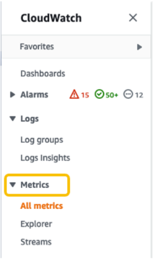
- In the navigation pane, choose Metrics.

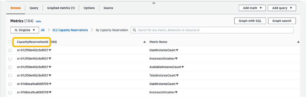
For All metrics, choose EC2 Capacity Reservations.

4. Choose the metric dimension By Capacity Reservation. Metrics will be grouped by

5. Select the dropdown arrow for InstanceUtilization, and select Search for this only.

Once we see the InstanceUtilization metric in the filter list, select Graph Search.

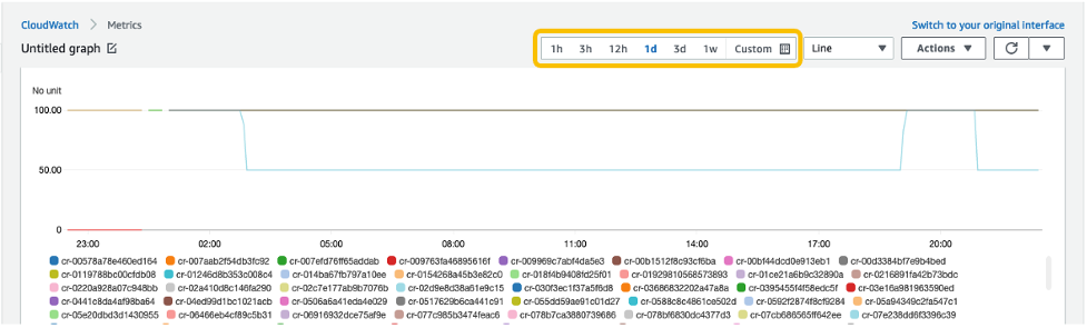
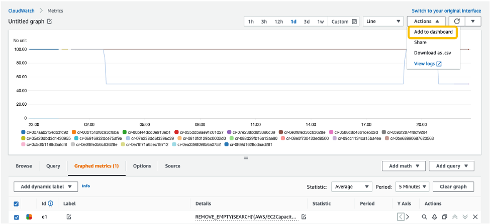
This displays the InstanceUtilization metrics for the selected period.

OPTIONAL: To display the Capacity Reservation IDs for active metrics only:
-
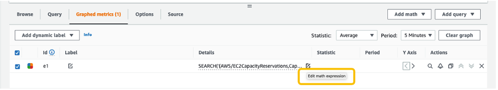
- Navigate to Graphed metrics.

-
- Under Details column, select Edit math expression.

-
- Edit the math expression with the following, and select Apply:
REMOVE_EMPTY(SEARCH('{AWS/EC2CapacityReservations,CapacityReservationId} MetricName="InstanceUtilization"', 'Average', 300))
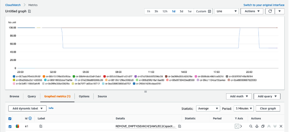
This displays the Capacity Reservation IDs for active metrics only.

With this configuration, whenever new Capacity Reservations are created, the InstanceUtilization metric for respective Capacity Reservation IDs will be populated.
6. From the Actions drop-down menu, select Add to dashboard.

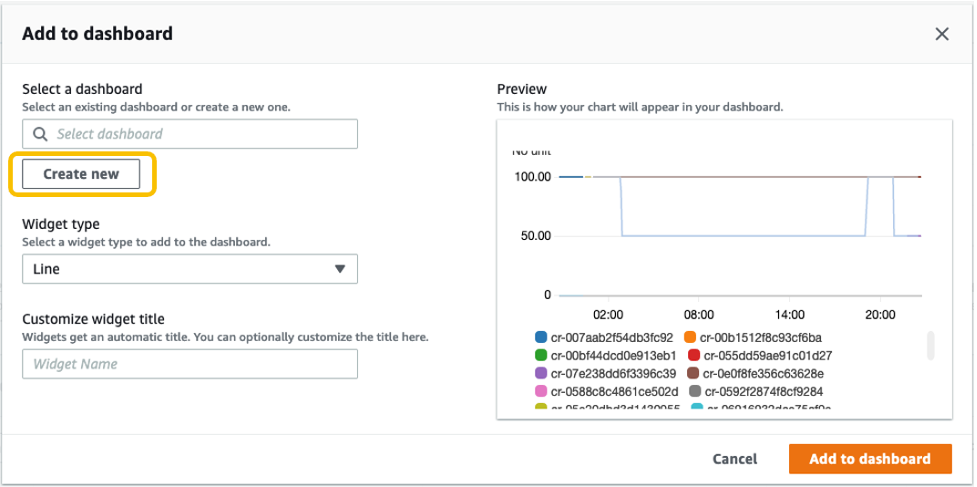
Select Create new to create a new dashboard for monitoring your ODCR metrics.

Specify the new dashboard name, and select Add to dashboard.

7. These configuration steps will navigate you to your newly created CloudWatch dashboard under Dashboards.

Once this is created, if you create new Capacity Reservations, or new instances get added to existing reservations, then those metrics will be automatically be added to your CloudWatch Dashboard.
Note: You may see a delay of approximately 5-10 minutes from the point when changes are made to your environment (ODCR operations or instances launch/termination activities) to those changes getting reflected on your CloudWatch Dashboard metrics.
Conclusion
In this post, we discussed a solution for automating ODCR operations for existing EC2 instances. This included creating capacity reservation, modifying capacity reservation, and cancelling capacity reservation operations that inherit your existing EC2 instances for attribute details. We also discussed monitoring aspects of ODCR metrics using CloudWatch. This solution allows you to automate some of the ODCR operations for existing instances, thereby optimizing and speeding up the entire process.
For more information, see Target a group of Amazon EC2 On-Demand Capacity Reservations blog and Capacity Reservations documentation.
If you have feedback or questions about this post, please submit your comments in the comments section or contact AWS Support.


 The AWS Summit season is mostly over in Asia Pacific and Europe, but there are some upcoming virtual and in-person Summits that might be close to you in June:
 Please join
  You can now register for