Tag Archives: AWS Outposts

Hybrid Cloud Journey using Amazon Outposts and AWS Local Zones

Post Syndicated from Arun Chellappa Ganesan original https://aws.amazon.com/blogs/architecture/hybrid-cloud-journey-using-amazon-outposts-and-aws-local-zones/

This post was co-written with Amy Flanagan, Vice President of Architecture and leader of the Virtual Architecture Team (VAT) at athenahealth, and Anusha Dharmalingam, Executive Director and Senior Architect at athenahealth.

athenahealth has embarked on an ambitious journey to modernize its technology stack by leveraging AWS’s hybrid cloud solutions. This transformation aims to enhance scalability, performance, and developer productivity, ultimately improving the quality of care provided to its patients.

athenahealth’s core products, including revenue cycle management, electronic health records, and patient engagement portals, have been built and refined over 25 years. The company initially deployed its Perl-based web application stack centrally in data centers, allowing it to scale horizontally to meet the growing demands of healthcare providers. However, as the company expanded, it encountered significant scaling and operational challenges in maintaining legal applications due to its monolithic architecture and tightly coupled codebase.

The need for modernization

With a legacy system acting as a multi-purpose database, athenahealth faced issues with developer productivity and operational efficiency. The monolithic architecture led to complex dependencies and made it difficult to implement new features. Realizing the need to modernize, athenahealth decided to refactor its applications and move to the cloud, taking advantage of AWS’s robust infrastructure and services.

Decomposing monoliths to microservices

athenahealth adopted the strangler fig pattern to decompose its monolithic applications into microservices. Starting with peripheral services, they gradually moved to core services, using containers and modern development practices. 80% of athenahealth’s AWS footprint are containerized workloads deployed on Amazon Elastic Container Service (Amazon ECS). Java became the primary language for these microservices, with purpose-built databases like Amazon DynamoDB, Amazon RDS for PostgreSQL, and Amazon OpenSearch.

Event-driven communication between services was facilitated through Amazon EventBridge, Amazon Managed Streaming for Apache Kafka (Amazon MSK), and Amazon Simple Queue Service (Amazon SQS). A data lake was established on Amazon Simple Storage Service (Amazon S3), fed by change data capture from relational databases. Despite progress, refactoring core services proved time-consuming and challenging.

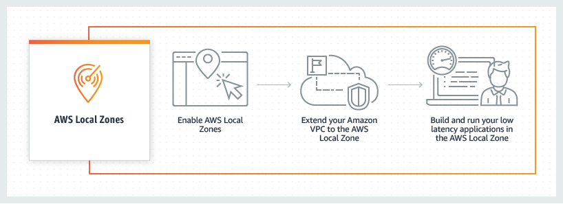
Introducing AWS Outposts and AWS Local Zones

To address these challenges, athenahealth leveraged AWS Local Zones and AWS Outposts, extending AWS infrastructure and services to their on-premises data centers. This hybrid cloud approach allowed athenahealth to deploy modernized code while maintaining low-latency access to existing databases. Deployment across both AWS Local Zones close to the datacenter and AWS Outposts in the datacenter enabled athenahealth to get a highly available hybrid architecture. Local Zones offers additional elasticity, making it suitable for specific use cases. Additionally, the combination of deployment solutions enables optimal access to athenahealth on-premises services and AWS Regional services.

Benefits of AWS Outposts and AWS Local Zones

  • Scalability and performance: Outposts and Local Zones enabled athenahealth to curb the growth of their monolithic codebase, allowing for seamless integration of modern microservices with existing systems.
  • Developer productivity: Developers were able to focus on container-based workloads, using familiar tools and environments, thereby reducing context switching and improving efficiency.
  • Operational efficiency: By running containerized applications on Outposts and Local Zones, athenahealth achieved consistent performance and reliability, crucial for healthcare applications.

Hybrid cloud architecture

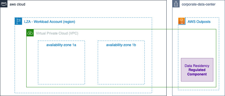
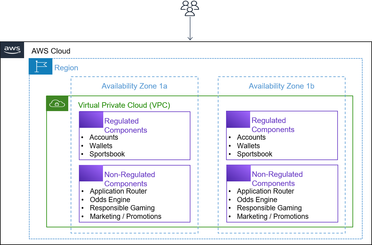
athenahealth’s hybrid cloud architecture includes two data centers geographically distributed for high availability and disaster recovery. As shown in Figure 1, the company operates two data centers that are geographically distributed, each housing two Outposts and connecting to two Local Zones. This configuration not only supports geo-proximity-based traffic distribution for optimal performance but also establishes a primary and standby setup for disaster recovery purposes. By connecting these Outposts to separate AWS Regions, athenahealth achieves additional redundancy, enhancing their system’s resilience and ensuring continuous operation. In addition, within a single Region the deployment across Outpost and Local Zone provides high availability for the applications. This hybrid setup enables athenahealth to seamlessly integrate their legacy monolithic application with modernized microservices. By using AWS Outposts and AWS Local Zones as an extension of their data centers, athenahealth can run containerized applications with low-latency access to on-premises databases. This architecture supports the company’s goals of curbing the growth of their monolithic codebase and improving developer productivity by allowing for consistent performance and reliability across their infrastructure. With two Outposts and two Local Zones deployed, athenahealth ensures that their critical healthcare services remain available and reliable, meeting the stringent demands of the industry.

AWS Outposts and AWS Local Zones at athenahealth

Figure 1. AWS Outposts and AWS Local Zones at athenahealth

Application deployment

athenahealth’s hybrid cloud architecture is designed to optimize the deployment of containerized workloads while ensuring efficient use of AWS Outposts’ capacity and elastic AWS Local Zone capacity. By leveraging Amazon Elastic Kubernetes Service (EKS), athenahealth deploys application containers on Outposts and AWS Local Zones, enabling low-latency access to on-premises databases. The control plane for these applications is managed in the AWS Region, while the worker nodes run locally on the Outposts and Local Zones. This setup ensures that critical applications requiring immediate data access can operate with minimal latency, thereby maintaining high performance and reliability.

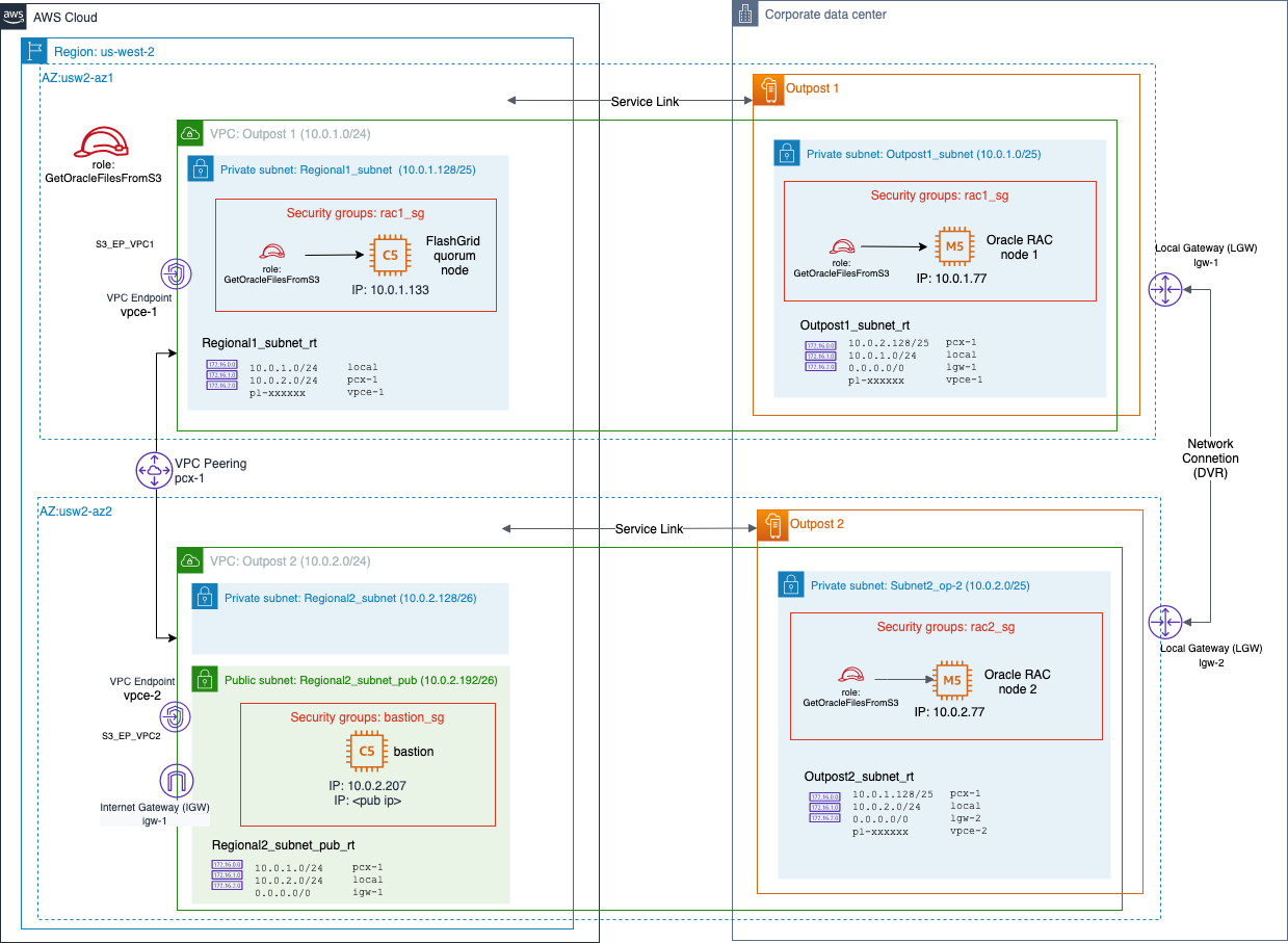
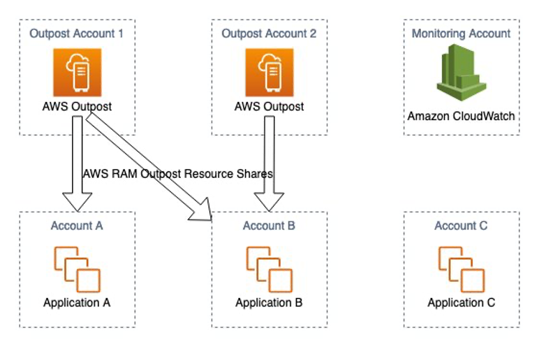
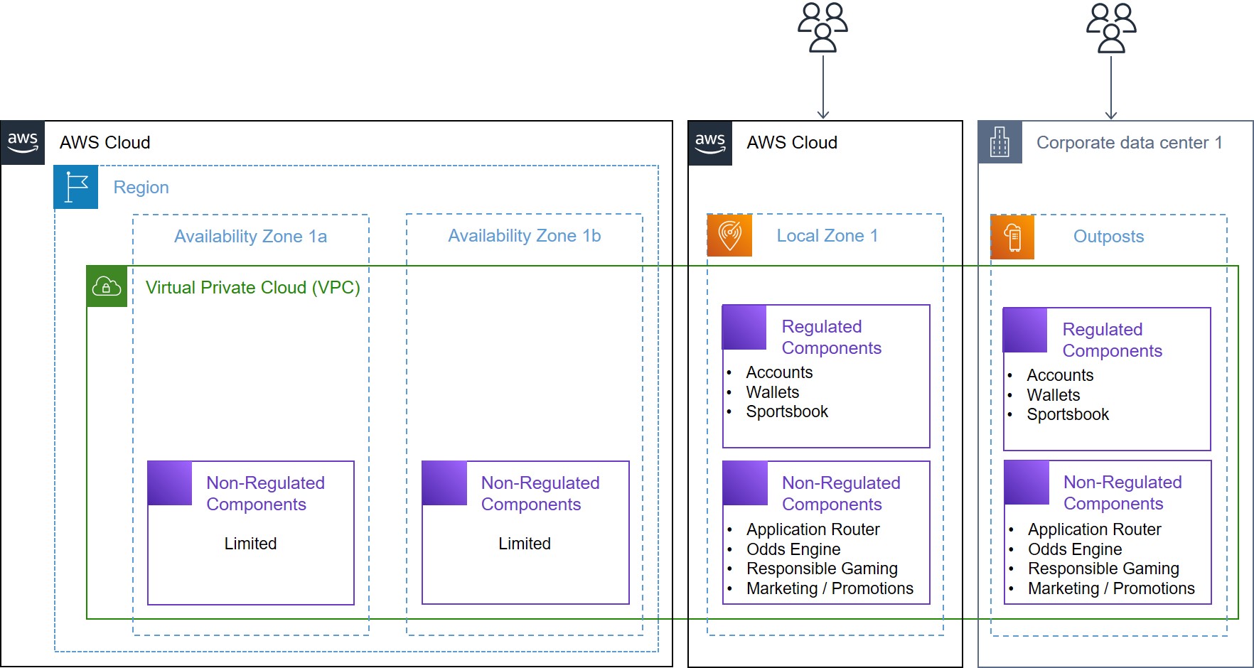
To further optimize the use of AWS resources, athenahealth deploys non-latency-sensitive services, such as logging, monitoring, and CI/CD, directly in AWS Regions, as shown in Figure 2. These services do not require direct access to on-premises databases, allowing athenahealth to preserve the limited capacity of Outposts for applications that truly benefit from low-latency access. By strategically dividing the deployment of applications between Outposts and Local Zones and AWS Regions, athenahealth achieves a balanced, efficient, and scalable hybrid cloud environment that supports the company’s ongoing modernization efforts.

Amazon EKS on Amazon Outposts

Figure 2. Amazon EKS on Amazon Outposts

Primary use cases

athenahealth’s primary use cases for their hybrid cloud architecture focus on curbing the growth of their monolithic codebase while facilitating modernization and cloud migration. By leveraging AWS Outposts and AWS Local Zones, they supported two key use cases:

  • Enabling microservices running in AWS Regions to access on-premises databases with low latency
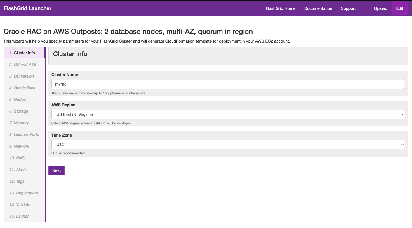
  • Offloading certain features of their monolithic application to Outposts and Local Zones, as shown in Figure 3

This approach reduces the load on legacy systems and enhances service delivery. These strategies allow athenahealth to maintain efficient operations and accelerate their transition to a hybrid cloud-based infrastructure.

Microservices running in AWS Regions interact with on-premises databases through Outposts and Local Zones, ensuring low-latency data access

Figure 3. Microservices running in AWS Regions interact with on-premises databases through Outposts and Local Zones, ensuring low-latency data access

Conclusion

This technology transformation is a significant step forward, enabling athenahealth to be more agile, efficient, and responsive to the evolving needs of its vast network of healthcare providers and patients. athenahealth’s journey to AWS hybrid cloud showcases the transformative power of modernizing legacy systems. With increased scalability, improved application performance, and streamlined developer workflows, the company can now focus even more on its core mission of delivering innovative, patient-centric solutions that improve health outcomes. As athenahealth progresses, it will continue to refine its hybrid cloud strategy, ensuring the delivery of high-quality healthcare services to clinicians and patients alike.

Further reading

Migrating your on-premises workloads to AWS Outposts rack

Post Syndicated from Macey Neff original https://aws.amazon.com/blogs/compute/migrating-your-on-premises-workloads-to-aws-outposts-rack/

This post is written by Craig Warburton, Senior Solutions Architect, Hybrid. Sedji Gaouaou, Senior Solutions Architect, Hybrid. Brian Daugherty, Principal Solutions Architect, Hybrid.

Migrating workloads to AWS Outposts rack offers you the opportunity to gain the benefits of cloud computing while keeping your data and applications on premises.

For organizations with strict data residency requirements, by deploying AWS infrastructure and services on premises, you can keep sensitive data and mission-critical applications within your own data centers or facilities, helping ensure compliance with data sovereignty laws and regulatory frameworks.

On the other hand, if your organization does not have stringent data residency requirements, you may opt for a hybrid approach, using both Outposts rack and the AWS Regions. With this flexibility, you can process and store data in the most appropriate location based on factors such as latency, cost optimization, and application requirements.

In this post, we cover the best options to migrate your workloads to Outposts rack, taking into account your specific data residency requirements. We explore strategies, tools, and best practices to enable a successful migration tailored to your organization’s needs.

Overview

AWS has a number of services to help you migrate and rehost workloads, including AWS Migration Hub, AWS Application Migration Service, AWS Elastic Disaster Recovery. Alternatively, you can use backup and recovery solutions provided by AWS partners.

At AWS, we use the 7 Rs framework to help organizations evaluate and choose the appropriate migration strategy for moving applications and workloads to the AWS Cloud. The 7 Rs represent:

  1. Rehosting (rehost or lift and shift)
  2. Replatforming (lift, tinker, and shift)
  3. Repurchasing (republish or re-vendor)
  4. Refactoring (re-architecting)
  5. Retiring
  6. Retaining (revisit)
  7. Relocating (remigrate).

This post focuses on rehosting and the services available to help rehost on-premises applications to Outposts rack.

Before getting started with any migration, AWS recommends a three-phase approach to migrating workloads to the cloud (AWS Region or Outposts rack). The three phases are assess, mobilize, and migrate and modernize.

Diagram showing the three migration phases of assess, mobilize, and migrate and modernize

Figure 1: Diagram showing the three migration phases of assess, mobilize, and migrate and modernize

This post describes the steps that you can take in the migrate and modernize phase. However, the assess and mobilize phases are also critical to allow you to understand what applications will be migrated, the dependencies between them, and the planning associated with how and when migration will occur.

AWS Migration Hub is a cloud migration service provided by AWS that helps organizations accelerate and simplify the process of migrating workloads to AWS. It provides a unified location to track the progress of application migrations across multiple AWS and partner services. This service can be used to help work through all three phases of migration, and we recommend that you start with this service and complete each phase accordingly. The assess phase should help you identify any applications that require consideration when migrating (including any data residency requirements), and the mobilize phase defines the approach to take.

Workload migration to AWS Outposts rack: With staging environment in an AWS Region

After deploying an Outpost rack to your desired on-premises location, you can perform migrations of on-premises systems and virtual machines using either Application Migration Service or third-party backup and recovery services. Both scenarios are described in the following sections.

Scenario 1: Using AWS Application Migration Service

Application Migration Service is able to lift and shift a large number of physical or virtual servers without compatibility issues, performance disruption, or long cutover windows.

In this scenario, at least one Outpost rack is deployed on premises with the following prerequisites:

  • At least one Outpost rack installed and activated
  • The Outposts rack must be in Direct VPC Routing (DVR) mode
  • VPC in Region containing subnet for staging resources
  • VPC extended to the Outposts rack containing subnet for target resources
  • An AWS Replication Agent installed on each source server

The following diagram shows the solution architecture and includes the on-premises servers that will be migrated from the local network to the Outposts rack. It also includes the staging VPC in Region used to deploy the replication servers, Amazon S3 to store the Amazon EBS snapshots and the target VPC extended to Outposts rack.

Architecture diagram showing migration with Application Migration Service

Figure 2: Architecture diagram showing migration with Application Migration Service

Step 1: Outposts rack configuration

You can work with AWS specialists to size your Outpost for your workload and application requirements. In this scenario, you don’t need additional Outposts rack capacity for the migration because the staging area will be deployed in the Region (see 1 in Figure 2).

Step 2: Prepare Application Migration service

Set up Application Migration Service from the console in the Region your Outposts rack is anchored to. If this is your first setup, choose Get started on the AWS Application Migration Service console. When creating the replication settings template, make sure your staging area is using subnets in the parent Region (see 2 in Figure 2).

Step 3: Install the AWS Replication Agent to the source servers or machines

For large migrations, source servers may have a wide variety of operating system versions and may be distributed across multiple data centers. AWS Application Migration Service offers the MGN connector, a feature that allows you to automate running commands on your source environment. Finally, ensure that communication is possible between the agent and Application Migration Service (see 3 in Figure 2).

In the following image, there is an example of deploying the AWS Replication Agent providing the required parameters (Region, AWS access key and AWS secret access key).

Once the AWS Replication Agent is installed, the server will be added to the AWS Application Migration Service console. Next, it will undergo the initial sync process, which will be completed when showing the Ready for testing lifecycle state in the Application Migration Service console.

Step 4: Configure launch settings

Prior to testing or cutting over an instance, you must configure the launch settings by creating Amazon Elastic Compute Cloud (Amazon EC2) launch templates, ensuring that you select your extended virtual private cloud (VPC) and subnet deployed on Outposts rack and using an appropriate, available instance type (see 4 in Figure 2).

To identify EC2 instances configured on your Outpost, you can use the following AWS Command Line Interface (AWS CLI):

Outposts get-outpost-instance-types \

--outpost-id op-abcdefgh123456789

The output of this command lists the instance types and sizes configured on your Outpost:

InstanceTypes:

- InstanceType: c5.xlarge

- InstanceType: c5.4xlarge

- InstanceType: r5.2xlarge

- InstanceType: r5.4xlarge

With knowledge of the instance types configured, you can now determine how many of each are available. For example, the following AWS CLI command, which is run on the account that owns the Outpost, lists the number of c5.xlarge instances available for use:

aws cloudwatch get-metric-statistics \

--namespace AWS/Outposts \

--metric-name AvailableInstanceType_Count \

--statistics Average --period 3600 \

--start-time $(date -u -Iminutes -d '-1hour') \

--end-time $(date -u -Iminutes) \

--dimensions \

Name=OutpostId,Value=op-abcdefgh123456789 \

Name=InstanceType,Value=c5.xlarge

This command returns:

Datapoints:

- Average: 10.0

  Timestamp: '2024-04-10T10:39:00+00:00'

  Unit: Count

Label: AvailableInstanceType_Count

The output indicates that there were (on average) 10 c5.xlarge instances available in the specified time period (1 hour). Using the same command for the other instance types, you discover that there are also 20 c5.4xlarge, 10 r5.2xlarge, and 6 r5.4xlarge available for use in completing the required EC2 launch templates.

Step 5: Install AWS Systems Manager Agent in your on your target instances

Once the launch settings are defined, you must activate the post-launch actions for either a specific server or all the servers. You must leave the Install the Systems Manager agent and allow executing actions on launched servers option toggled on in order for post-launch actions to work. Untoggling the option would disallow Application Migration Service to install the AWS Systems Manager Agent (SSM Agent) on your servers, and post-launch actions would no longer be executed on them (see 5 in Figure 2).

Post-launch actions on the Application Migration Service console

Figure 3: Post-launch actions on the Application Migration Service console

Step 6: Testing and cutover

Once you have configured the launch settings for each source server, you are ready to launch the servers as test instances. Best practice is to test instances before cutover.

Application Migration Service console ready to launch test instances

Figure 4: Application Migration Service console ready to launch test instances

Finally, after completing the testing of all the source servers, you are ready for cutover (see 6 on Figure 2). Prior to launching cutover instances, check that the source servers are listed as Ready for cutover under Migration lifecycle and Healthy under Data replication status.

Figure 5: Application Migration Console ready for cutover

To launch the cutover instances, select the instances you want to cutover and then select Launch cutover instances under Cutover (see Figure 5).

The AWS Application Migration Service console will indicate Cutover finalized when the cutover has completed successfully, the selected source servers’ Migration lifecycle column will show the Cutover complete status, the Data replication status column will show Disconnected, and the Next step column will show Mark as archived. The source servers have now been successfully migrated into AWS. You can now archive your source servers that have launched cutover instances.

Scenario 2: Using partner backup and replication solutions

You may already be using a third-party or AWS Partner solution to create on-premises backups of bare-metal or virtualized systems. These solutions often use local disk-arrays or object stores to create tiered backups of systems covering restore-points going back years, days, or just a few hours or minutes.

These solutions may also have inherent capabilities to restore from these backups directly to the AWS, enabling migration of on-premises systems to EC2 instances deployed to Outposts rack.

In the scenario illustrated in Figure 6, the partner backup and replication service (BR) creates backups (see 1 in Figure 6) of virtual machines to on-premises disk or object storage repositories. Using the service’s AWS integration, virtual machines can be restored (see 2 in Figure 6) to an EC2 instance deployed on Outposts rack, which is also on premises. The restoration may follow a process that uses helper instances and volumes (see 3 in Figure 6) during intermediate steps to create Amazon Elastic Block Store (Amazon EBS) snapshots (see 4 in Figure 6) and then Amazon Machine Images (AMIs) of the systems being migrated (see 5 in Figure 6), which are ultimately deployed (see 6 in Figure 6) to Outposts rack.

Architecture diagram of the partner backup and replication scenario

Figure 6: Architecture diagram of the partner backup and replication scenario

When performing this type of migration, there will typically be a stage where you are asked to specify parameters defining the target VPC and subnets. These should be the VPC being extended to the Outpost and a subnet that has been created in that VPC on the Outpost. You will also need to specify an EC2 instance type that is available on the Outpost, which can be discovered using the process described in the previous section.

Workload migration to AWS Outposts rack: With staging environment on an AWS Outpost rack

Data residency can be a critical consideration for organizations that collect and store sensitive information, such as personally identifiable information (PII), financial data or medical records. AWS Elastic Disaster Recovery, supported on Outposts rack, helps enable seamless replication of on-premises data to Outposts rack and addresses data residency concerns by keeping data within your on-premises environment, using Amazon EBS and Amazon S3 on Outposts.

In this scenario, an Outpost rack is deployed on premises with the following prerequisites:

  • At least one Outpost rack installed and activated
  • The Outposts rack must be in Direct VPC Routing (DVR) mode
  • VPC extended to the Outposts rack containing subnets for staging and target resources
  • Amazon S3 on Outposts (required for all Elastic Disaster Recovery replication destinations)
  • An AWS Replication Agent installed on each source server.

The following diagram shows the solution architecture and includes the on-premises servers that will be migrated from the local network to the Outposts rack. It also includes the staging VPC used to deploy the replication servers on Outposts rack, Amazon S3 on Outposts to store the local Amazon EBS snapshots and the target VPC extended to Outposts rack.

Figure 7: Architecture diagram for workflow migration to AWS Outposts rack

Step 1: Outposts rack configuration

To use Elastic Disaster Recovery on Outposts rack, you need to configure both Amazon EBS and Amazon S3 on Outposts to support nearly continuous replication and point-in-time recovery for your workload needs (see 1 in Figure 7). Specifically, you need to size Amazon EBS and Amazon S3 on Outposts capacity according to your workload capacity requirements and application interdependencies. To do this, you can define dependency groups–each dependency group is a collection of applications and their underlying infrastructure with technical or non-technical dependencies. A 2:1 ratio is recommended for the EBS volumes to be used for near-continuous replication; a 1:1 ratio is recommended for the Amazon S3 on Outposts ratio for EBS snapshots. For example, to migrate 40 terabytes (TB) of workloads, you need to plan for 80TB of EBS volumes and 40TB of S3 on Outposts capacity.

Step 2: Extend VPC to your Outposts rack

Once your Outpost has been provisioned and is available, extend the required Amazon Virtual Private Cloud (Amazon VPC) connection to the Outpost from the Region by creating the desired staging and target subnets (see 2 in Figure 7).

Step 3: Prepare AWS Elastic Disaster Recovery service

Prepare the AWS Elastic Disaster Recovery service from the AWS console to set the default replication and launch settings. When defining these settings, make sure that the Outposts resources available are chosen for staging and target subnets and instance and storage type (see 3 in Figure 7).

Step 4: Install the AWS Replication Agent to the source servers or machines

The next phase will be to install the AWS Replication Agent to the source servers and to ensure that communication is possible between the replication agent and your Outposts replication subnet through the Outposts local gateway to ensure that replication traffic uses the local network (see 4 in Figure 7).

Step 5: Continuous block-level replication

Staging area resources are automatically created and managed by Elastic Disaster Recovery. Once the AWS Replication Agent has been deployed, continuous block-level replication (compressed and encrypted in transit) will occur (see 5 in Figure 7) over the local network.

Step 6: Launch Outposts rack resources

Finally, migrated instances can now be launched using Outposts rack resources based on the launch settings defined previously (see 6 in Figure 7).

Conclusion

In this post, you have learned how to migrate your workloads from your on-premises environment to Outposts rack based on your specific data residency requirements. When you have the flexibility of using Regional services, AWS migration services or partner solutions can be used with infrastructure already in place. If your data must stay on-premises, using AWS Elastic Disaster Recovery allows you to migrate your data without using Regional services, allowing you to migrate to Outposts rack without your data leaving the boundary of a certain geographic location.

To learn more about an end-to-end migration and modernization journey, visit AWS Migration Hub.

Implementing network traffic inspection on AWS Outposts rack

Post Syndicated from Macey Neff original https://aws.amazon.com/blogs/compute/implementing-network-traffic-inspection-on-aws-outposts-rack/

This blog post is written by Brian Daugherty, Principal Solutions Architect. Enrico Liguori, Solution Architect, Networking. Sedji Gaouaou, Senior Solution Architect, Hybrid Cloud.

Network traffic inspection on AWS Outposts rack is a crucial aspect of making sure of security and compliance within your on-premises environment. With network traffic inspection, you can gain visibility into the data flowing in and out of your Outposts rack environment, enabling you to detect and mitigate potential threats proactively.

By deploying AWS partner solutions on Outposts rack, you can take advantage of their expertise and specialized capabilities to gain insights into network traffic patterns, identify and mitigate threats, and help ensure compliance with industry-specific regulations and standards. This includes advanced network traffic inspection capabilities, such as deep packet inspection, intrusion detection and prevention, application-level firewalling, and advanced threat detection.

This post presents an example architecture of deploying a firewall appliance on an Outposts rack to perform on-premises to Virtual Private Cloud (VPC) and VPC-to-VPC inline traffic inspection.

Architecture

The example traffic inspection architecture illustrated in the following diagram is built using a common Outposts rack deployment pattern.

In this example, an Outpost rack is deployed on premises to support:

  • Manufacturing/operational technologies (OT) applications that need low latency between OT servers and devices
  • Information technology (IT) applications that are subject to strict data residency and data protection policies

Separate VPCs, that can be owned by different AWS accounts, and subnets are created for the IT and OT departments’ instances (see 1 and 2 in the diagram).

Organizational security policies require that traffic flowing to and from the Outpost and the site, and between VPCs on the Outpost, be inspected, controlled, and logged using a centralized firewall.

In an AWS Region it is possible to implement a centralized traffic inspection architecture using routing services such as AWS Transit Gateways (TGW) or Gateway Load Balancers (GWLB) to route traffic to a central firewall, but these services are not available on Outposts.

On Outposts, some use the Local Gateway (LGW) to implement a distributed traffic inspection architecture with firewalls deployed in each VPC, but this can be operationally complex and cost prohibitive.

In this post, you will learn how to use a recently introduced feature – Multi-VPC Elastic Network Interface (ENI) Attachments – to create a centralized traffic inspection architecture on Outposts. Using Multi-VPC Attached ENIs you can attach ENIs created in subnets that are owned and managed by other VPCs (even VPCs in different accounts) to an Amazon Elastic Compute Cloud (EC2) instance.

Specifically, you can create ENIs in the IT and OT subnets that can be shared with a centralized firewall (see 3 and 4).

Because it’s a best practice to minimize the attack surface of a centralized firewall through isolation, the example includes a VPC and subnet created solely for the firewall instance (see 5).

To protect traffic flowing to and from the IT, OT, and firewall VPCs and on-site networks, another ‘Exposed’ VPC, subnet (see 6), and ENI (see 7) are created. These are the only resources associated with the Outposts Local Gateway (LGW) and ‘exposed’ to on-site networks.

In the example, traffic is routed from the IT and OT VPCs using a default route that points to the ENI used by the firewall (see 8 and 9). The firewall can route traffic back to the IT and OT VPCs, as allowed by policy, through its directly connected interfaces.

The firewall uses a route for the on-site network (192.168.30.0/24) – or a default route – pointing to the gateway associated with the exposed ENI (eni11, 172.16.2.1 – see 10).

To complete the routing between the IT, OT, and firewall VPCs and the on-site networks, static routes are added to the LGW route table pointing to the firewall’s exposed ENI as the next hop (see 11).

Once these static routes are inserted, the Outposts Ingress Routing feature will trigger the routes to be advertised toward the on-site layer-3 switch using BGP.

Likewise, the on-site layer-3 switch will advertise a route (see 12) for 192.168.30.0/24 (or a default route) over BGP to the LGW, completing end-to-end routing between on-site networks and the IT and OT VPCs through the centralized firewall.

The following diagram shows an example of packet flow between an on-site OT device and the OT server, inspected by the firewall:

Implementation on AWS Outposts rack

The following implementation details are essential for our example traffic inspection on the Outposts rack architecture.

Prerequisites

The following prerequisites are required:

  • Deployment of an Outpost on premises;
  • Creation of four VPCs – Exposed, firewall, IT, and OT;
  • Creation of private subnets in each of the four VPCs where ENIs and instances can be created;
  • Creation of ENIs in each of the four private subnets for attachment to the firewall instance (keep track of the ENI IDs);
  • If needed, sharing the subnets and ENIs with the firewall account, using AWS Resource Access Manager (AWS RAM);
  • Association of the Exposed VPC to the LGW.

Firewall selection and sizing

Although in this post a basic Linux instance is deployed and configured as the firewall, in the Network Security section of the AWS Marketplace, you can find several sophisticated, powerful, and manageable AWS Partner solutions that perform deep packet inspection.

Most network security marketplace offerings provide guidance on capabilities and expected performance and pricing for specific appliance instance sizes.

Firewall instance selection

Currently, an Outpost rack can be configured with EC2 instances in the M5, C5, R5, and G4dn families. As a user, you can select the size and number of instances available on an Outpost to match your requirements.

When selecting an EC2 instance for use as a centralized firewall it is important to consider the following:

  • Performance recommendations for instance types and sizes made by the firewall appliance partner;
  • The number of VPCs that are inspected by the firewall appliance;
  • The availability of instances on the Outpost.

For example, after evaluating the partner recommendations you may determine that an instance size of c5.large, r5.large, or larger provide the required performance.

Next, you can use the following AWS Command Line Interface (AWS CLI) command to identify the EC2 instances configured on an Outpost:

Outposts get-outpost-instance-types \
--outpost-id op-abcdefgh123456789

The output of this command lists the instance types and sizes configured on your Outpost:

InstanceTypes:
- InstanceType: c5.xlarge
- InstanceType: c5.4xlarge
- InstanceType: r5.2xlarge
- InstanceType: r5.4xlarge

With knowledge of the instance types and sizes installed on your Outpost, you can now determine if any of these are available. The following AWS CLI command – one for each of the preceding instance types – lists the number of each instance type and size available for use. For example:

aws cloudwatch get-metric-statistics \
--namespace AWS/Outposts \
--metric-name AvailableInstanceType_Count \
--statistics Average --period 3600 \
--start-time $(date -u -Iminutes -d '-1hour') \
--end-time $(date -u -Iminutes) \
--dimensions \
Name=OutpostId,Value=op-abcdefgh123456789 \
Name=InstanceType,Value=c5.xlarge

This command returns:

Datapoints:
- Average: 2.0
  Timestamp: '2024-04-10T10:39:00+00:00'
  Unit: Count
Label: AvailableInstanceType_Count

The output indicates that there are (on average) two c5.xlarge instances available on this Outpost in the specified time period (1 hour). The same steps for the other instance type suggest that there are also two c5.4xlarge, two r5.2xlarge, and no r5.4xlarge available.

Next, consider the number of VPCs to be connected to the firewall and determine if the instances available support the required number of ENIs.

The firewall requires an ENI in its own VPC, in the Exposed VPC, and one for each additional VPC. In this post, because there is a VPC for IT and for OT, you need an EC2 instance that supports four interfaces in total:

To determine the number of supported interfaces for each available instance type and size, let’s use the AWS CLI:

aws ec2 describe-instance-types \
--instance-types c5.xlarge c5.4xlarge r5.2xlarge \
--query 'InstanceTypes[].[InstanceType,NetworkInfo.NetworkCards]'

This returns:

- - r5.2xlarge
  - - BaselineBandwidthInGbps: 2.5
      MaximumNetworkInterfaces: 4
      NetworkCardIndex: 0
      NetworkPerformance: Up to 10 Gigabit
      PeakBandwidthInGbps: 10.0
- - c5.xlarge
  - - BaselineBandwidthInGbps: 1.25
      MaximumNetworkInterfaces: 4
      NetworkCardIndex: 0
      NetworkPerformance: Up to 10 Gigabit
      PeakBandwidthInGbps: 10.0
- - c5.4xlarge
  - - BaselineBandwidthInGbps: 5.0
      MaximumNetworkInterfaces: 8
      NetworkCardIndex: 0
      NetworkPerformance: Up to 10 Gigabit
      PeakBandwidthInGbps: 10.0

The output suggests that the three available EC2 instances (r5.2xlarge, c5.xlarge and c5.4xlarge) can support four network interfaces. The output also suggests that the c5.4xlarge instance, for example, supports up to 8 network interfaces and a maximum bandwidth of 10Gb/s. This helps you plan for the potential growth in network requirements.

Attaching remote ENIs to the firewall instance

With the firewall instance deployed in the firewall VPC, the next step is to attach the remote ENIs created previously in the Exposed, OT, and IT subnets. Using the firewall instance ID and the Network Interface IDs for each of the remote ENIs, you can create the Multi-VPC Attached ENIs to connect the firewall to the other VPCs.  Each attached interface needs a unique device-index greater than ‘0’ which is the primary instance interface.

For example, to connect the Exposed VPC ENI:

aws ec2 attach-network-interface --device-index 1 \
--instance-id i-0e47e6eb9873d1234 \
--network-interface-id eni-012a3b4cd5efghijk \
--region us-west-2

Attach the OT and IT ENIs while incrementing the device-index and using the respective unique ENI IDs:

aws ec2 attach-network-interface --device-index 2 \
--instance-id i-0e47e6eb9873d1234 \
--network-interface-id eni-0bbe1543fb0bdabff \
--region us-west-2
aws ec2 attach-network-interface --device-index 3 \
--instance-id i-0e47e6eb9873d1234 \
--network-interface-id eni-0bbe1a123b0bdabde \
--region us-west-2

After attaching each remote ENI, the firewall instance now has an interface and IP address in each VPC used in this example architecture:

ubuntu@firewall:~$ ip address

ens5: <BROADCAST,MULTICAST,UP,LOWER_UP> mtu 9001 qdisc mq state UP group default qlen 1000
    inet 10.240.4.10/24 metric 100 brd 10.240.4.255 scope global dynamic ens5

ens6: <BROADCAST,MULTICAST,UP,LOWER_UP> mtu 9001 qdisc mq state UP group default qlen 1000
    inet 10.242.0.50/24 metric 100 brd 10.242.0.255 scope global dynamic ens6

ens7: <BROADCAST,MULTICAST,UP,LOWER_UP> mtu 9001 qdisc mq state UP group default qlen 1000
    inet 10.244.76.51/16 metric 100 brd 10.244.255.255 scope global dynamic ens7

ens11: <BROADCAST,MULTICAST,UP,LOWER_UP> mtu 9001 qdisc mq state UP group default qlen 1000
    inet 172.16.2.7/24 metric 100 brd 172.16.2.255 scope global dynamic ens11

Updating the VPC/subnet route tables

You can now add the routes needed to allow traffic to be inspected to flow through the firewall.

For example, the OT subnet (10.242.0.0/24) uses a route table with the ID rtb- abcdefgh123456789. To send the traffic through the firewall, you need to add a default route with the target being the ENI (eni-07957a9f294fdbf5d) that is now attached to the firewall:

aws ec2 create-route --route-table-id rtb-abcdefgh123456789 \
--destination-cidr-block 0.0.0.0/0 \
--network-interface-id eni-07957a9f294fdbf5d

You can follow the same process is used to add a default route to the IT VPC/subnet.

With routing established from the IT and OT VPCs to the firewall, you need to make sure that the firewall uses the Exposed VPC to route traffic toward the on-premises network 192.168.30.0/24. This is done by adding a route within the firewall OS using the VPC gateway as a next hop.

The ENI attached to the firewall from the Exposed VPC is in subnet 172.16.2.0/28, and the gateway used by this subnet is, by Amazon Virtual Private Cloud (VPC) convention, the first address in the subnet – 172.16.2.1. This is used when updating the firewall OS route table:

sudo ip route add 192.168.30.0/24 via 172.16.2.1

You can now confirm that the firewall OS has routes to each attached subnet and to the on-premises subnet:

ubuntu@firewall:~$ ip route
default via 10.240.4.1 dev ens5 proto dhcp src 10.240.4.10 metric 100
10.240.0.2 via 10.240.4.1 dev ens5 proto dhcp src 10.240.4.10 metric 100
10.240.4.0/24 dev ens5 proto kernel scope link src 10.240.4.10 metric 100
10.240.4.1 dev ens5 proto dhcp scope link src 10.240.4.10 metric 100
10.242.0.0/24 dev ens6 proto kernel scope link src 10.242.0.50 metric 100
10.242.0.2 dev ens6 proto dhcp scope link src 10.242.0.50 metric 100
10.244.0.0/16 dev ens7 proto kernel scope link src 10.244.76.51 metric 100
10.244.0.2 dev ens7 proto dhcp scope link src 10.244.76.51 metric 100
172.16.2.0/24 dev ens11 proto kernel scope link src 172.16.2.7 metric 100
172.16.2.2 dev ens11 proto dhcp scope link src 172.16.2.7 metric 100
192.168.30.0/24 via 172.16.2.1 dev ens11

The final step in establishing end-to-end routing is to make sure that the LGW route table contains static routes for the firewall, IT, and OT VPCs. These routes target the ENIs used by the firewall in the Exposed VPC.

After gathering the LGW Route Table ID and the firewall’s Exposed ENI ID used by the firewall, you can now add routes toward the firewall VPC:

aws ec2 create-local-gateway-route \
    --local-gateway-route-table-id lgw-rtb-abcdefgh123456789 \
    --network-interface-id eni-0a2e4f68f323022c3 \
    --destination-cidr-block 10.240.0.0/16

Repeat this command for the OT and IT VPC CIDRs – 10.242.0.0/16 and 10.244.0.0/16, respectively.

You can query the LGW route table to make sure that each of the static routes was inserted:

aws ec2 search-local-gateway-routes \
    --local-gateway-route-table-id lgw-rtb-abcdefgh123456789 \
    --filters "Name=type,Values=static"

This returns:

Routes:

- DestinationCidrBlock: 10.240.0.0/16
  LocalGatewayRouteTableId: lgw-rtb-abcdefgh123456789
  NetworkInterfaceId: eni-0a2e4f68f323022c3
  State: active
  Type: static

- DestinationCidrBlock: 10.242.0.0/16
  LocalGatewayRouteTableId: lgw-rtb-abcdefgh123456789
  NetworkInterfaceId: eni-0a2e4f68f323022c3
  State: active
  Type: static

- DestinationCidrBlock: 10.244.0.0/16
  LocalGatewayRouteTableId: lgw-rtb-abcdefgh123456789
  NetworkInterfaceId: eni-0a2e4f68f323022c3
  State: active
  Type: static

With the addition of these static routes the LGW begins to advertise reachability to the firewall, OT, and IT Classless Inter-Domain Routing (CIDR) blocks over the BGP neighborship. The CIDR for the Exposed VPC is already advertised because it is associated directly to the LGW.

The firewall now has full visibility of the traffic and can apply the monitoring, inspection, and security profiles defined by your organization.

Other considerations

  • It is important to follow the best practices specified by the Firewall Appliance Partner to fully secure the appliance. In the example architecture, access to the firewall console is restricted to AWS Session Manager.
  • The commands used previously to create/update the Outpost/LGW route tables need an account with full privileges to administer the Outpost.

Fault tolerance

As a crucial component of the infrastructure, the firewall instance needs a mechanism for automatic recovery from failures. One effective approach is to deploy the firewall instances within an Auto Scaling group, which can automatically replace unhealthy instances with new, healthy ones. In addition, using host or rack level spread placement group makes sure that your instances are deployed on distinct underlying hardware. This enables high availability and minimizes downtime. Furthermore, this approach based on Auto Scaling can be implemented regardless of the specific third-party product used.

To ensure a seamless transition when Auto Scaling replaces an unhealthy firewall instance, it is essential that the multi-VPC ENIs responsible for receiving and forwarding traffic are automatically attached to the new instance. When re-using the same multi-VPC ENIs, make sure that no changes are required in the subnets and LGW route tables.

To re-attach the same multi-VPC ENIs to the new instance, you can do this using Auto Scaling lifecycle hooks, with which you can pause the instance replacement process and perform custom actions.

After re-attaching the multi-VPC ENIs to the instance, the last step is to restore the configuration of the firewall from a backup.

Conclusion

In this post, you have learned how to implement on-premises to VPC and VPC-to-VPC inline traffic inspection on Outposts rack with a centralized firewall deployment. This architecture requires a VPC for the firewall instance itself, an Exposed VPC connecting to your on-premises network, and one or more VPCs for your workloads running on the Outpost. You can either use a basic Linux instance as a router, or choose from the advanced AWS Partner solutions in the Network Security section of the AWS Marketplace and follow the respective guidance on firewall instance selection. With multi-VPC ENI attachments, you can create network traffic routing between VPCs and forward traffic to the centralized firewall for inspection. In addition, you can use Auto Scaling groups, spread placement groups, and Auto Scaling lifecycle hooks to enable high availability and fault tolerance for your firewall instance.

If you want to learn more about network security on AWS, visit: Network Security on AWS.

Architecting for Disaster Recovery on AWS Outposts Racks with AWS Elastic Disaster Recovery

Post Syndicated from Macey Neff original https://aws.amazon.com/blogs/compute/architecting-for-disaster-recovery-on-aws-outposts-racks-with-aws-elastic-disaster-recovery/

This blog post is written by Brianna Rosentrater, Hybrid Edge Specialist SA.

AWS Elastic Disaster Recovery Service (AWS DRS) now supports disaster recovery (DR) architectures that include on-premises Windows and Linux workloads running on AWS Outposts. AWS DRS minimizes downtime and data loss with fast, reliable recovery of on-premises and cloud-based applications using affordable storage, minimal compute, and point-in-time recovery. Both services are billed and managed from your AWS Management Console.

Like workloads running in AWS Regions, it’s critical to plan for failures. Outposts are designed with resiliency in mind, providing redundant power, networking, and are available to order with N+M active compute instance capacity. In other words, for every physical N compute servers, you have the option of including M redundant hosts capable of handling the workload during a failure. When leveraging AWS DRS with Outpost, you can plan for larger-scale failure modes, such as data center outages, by replicating mission-critical workloads to other remote data center locations or the AWS Region.

In this post, you’ll learn how AWS DRS can be used with Outpost rack to architect for high availability in the event of a site failure. The post will examine several different architectures enabled by AWS DRS that provide DR for Outpost, and the benefits of each method described.

Prerequisites

Each of these architectures described below need the following:

Public internet access isn’t needed, AWS PrivateLink and AWS Direct Connect are supported for replication and failback which is a significant security benefit.

Planning for failure

Disasters come in many forms and are often unplanned and unexpected events. Regardless of whether your workload resides on premises, in a colocation facility, or in an AWS Region, it’s critical to define the Recovery Time Objective (RTO) and Recovery Point Objective (RPO) which are often workload-specific. These two metrics profile how long a service can be down during recovery and quantify the acceptable amount of data loss. RTO and RPO guide you in choosing the appropriate strategy such as backup and recovery, pilot light, warm standby, or a multi-site (active-active) approach.

With AWS DRS, while failing back to a test machine (not the original source server), replication of the source server continues. This allows failback drills without impacting RPO, and non-disruptive failback drills are an important part of disaster planning to validate your recovery plan meets your expected RPO/RTO as per your business requirements.

How AWS DRS integrates with Outpost

AWS DRS uses an AWS Replication Agent at the source to capture the workload and transfer it to a lightweight staging area, which resides on an Outpost equipped with Amazon S3 on Outposts. This method also provides the ability to perform low-effort, non-disruptive DR drills before making the final cutover. The AWS Replication Agent doesn’t need a reboot nor does it impact your applications during installation.

When an Outpost’s subnet is selected as the target for replication or launch, all associated AWS DRS components remain within the Outpost, including the AWS DRS server conversion technology. These conversion servers convert source disks of servers being migrated so that they can boot and run in the target infrastructure, Amazon EBS volumes, snapshots, and replication servers. The replication servers replicate the disks to the target infrastructure. With AWS DRS you can control the data replication path using private connectivity options such as a virtual private network (VPN), AWS Direct Connect, VPC peering, or another private connection. Learn more about using a private IP for data replication.

AWS DRS provides nearly continuous replication for mission-critical workloads and supports deployment patterns including on-premises to Outpost, Outpost to Region, Region to Outpost, and between two logical Outposts through local networks. To leverage Outpost with AWS DRS, simply select the Outpost subnet as your target or source for replication when configuring AWS DRS for your workload. If you are currently using CloudEndure DR for disaster recovery with Outpost, see these detailed instructions for migrating to AWS DRS from CloudEndure DR.

DR from on-premises to Outpost

Outpost can be used as a DR target for on-premises workloads. By deploying an Outpost in a remote data center or colocation a significant distance from the source within the same geo-political boundary, you can replicate workloads across great distances and increase resiliency of the data while ensuring adherence to data residency policies or legislation.

DR from on-premises to Outposts

Figure 1 – DR from on-premises to Outposts

In Figure 1, on premises sources replicate traffic from a LAN to a staging area residing in an Outpost subnet via the local gateway. This allows workloads to failover from their on-premises environment to an Outpost in a different physical location during a disaster.

The staging areas and replication servers run on Amazon Elastic Compute Cloud (Amazon EC2) with Amazon EBS volumes and require Amazon S3 on Outposts where the Amazon EBS snapshots reside.

The replication agent is responsible for providing nearly continuous, block-level replication from your LAN using TCP/1500 with traffic routing to Amazon EC2 instances using the Outposts local gateway.

DR from Outpost to Region

Since its initial release, Outpost has supported Amazon EBS snapshots written to Amazon S3 located in the AWS Region. Backup to an AWS Region is one of the most cost-effective and easiest-to-configure DR approaches, enabling data redundancy outside of your Outpost and data center.

This method also offers flexibility for restoration within an AWS Region if the original deployment is irrecoverable. However, depending on the frequency of the snapshots and the timing of the failure, backup, and recovery to the Region has the potential to have an RPO/RTO spanning hours depending on the throughput of the service link.

For critical workloads, AWS DRS can reduce RTO to minutes and RPO in the sub-second range. After creating an initial replication of workloads that reside on the Outpost, AWS DRS provides nearly continuous, block-level replication in the Region. Just like replication from non-AWS virtual machines or bare metal servers, AWS DRS resources, including Replication Servers, Conversion Servers, Amazon EBS Volumes, and Snapshots reside in the Region.

DR from Outpost to Region

Figure 2 – DR from Outpost to Region

In Figure 2, data replication is performed over the service link from Amazon EC2 instances running locally on an Outpost to an AWS Region. The service link traverses either public Region connectivity or AWS Direct Connect.

AWS Direct Connect is the recommended option because it provides low latency and consistent bandwidth for the service link back to a Region, which also improves the reliability of transmission for AWS DRS replication traffic.

The service link is comprised of redundant, encrypted VPN tunnels. Replication traffic can also be sent privately without traversing the public internet by leveraging Private Virtual Interfaces with Direct Connect for the service link.

With this architecture in place, you can mitigate disasters and reduce downtime by failing over to the AWS Region using AWS DRS.

DR from Region to Outpost

AWS provides multiple Availability Zones (AZs) within a Region and isolated AWS Regions globally for the greatest possible fault tolerance and stability. The reliability pillar of AWS’s Well-Architected Framework encourages distributing workloads across AZs and replicating data between Regions when the need for distances exceeds those of AZs.

AWS DRS supports nearly continuous replication of workloads from a Region to an Outpost within your data center or colocation facility for DR. This deployment model provides increased durability from a source AWS Region to an Outpost anchored to a different Region.

In this model, AWS DRS components remain on-premises within the Outpost, but data charges are applicable as data egresses from the Region back to the data center and Amazon S3 on Outposts is required on the destination Outpost.

DR from Region to Outpost

Figure 3 – DR from Region to Outpost

Implementing the preceding architecture diagram enables failover of critical workloads from the Region to on-premises Outposts seamlessly. Keep in mind that AWS Regions provide the management and control plane for Outpost, making it critical to consider probability and frequency of service link interruptions as a part of your DR planning. Scenarios such as warm standby with pre-allocated Amazon EC2 and Amazon EBS resources may prove more resilient during service link disruptions.

DR between two Outposts

Each logical Outpost is comprised of one or more physical racks. Logical Outposts are in independent colocations of one another, and support deployments in disparate data centers or colocation facilities. You can elect to have multiple logical Outposts anchored to different Availability Zones or Regions. AWS DRS unlocks options for replication between two logical Outposts, leading to increased resiliency and reducing the impact of your data center as a single point of failure. In the following architecture, nearly continuous replication captured from a single Outpost source is applied at a second logical Outpost.

DR between two Outposts

Figure 4 – DR between two Outposts

Supporting both directional and bidirectional replication between Outposts can minimize disruption caused by events that take down a data center, Availability Zone, or even the entire Region result in minimal disruption. In the following architecture diagram, bidirectional data replication occurs between the Outposts by routing traffic via the local gateways, minimizing outbound data charges from the Region and allowing for more direct routing between deployment sites that could potentially span significant distances. AWS DRS cannot communicate with resources directly utilizing a customer-owned IP address pool (CoIP pool).

Figure 5 – DR between two Outposts – bidirectional 

Architecture Considerations

When planning an Outpost deployment leveraging AWS DRS, it’s critical to consider the impact on storage. As a general best practice, AWS recommends planning for a 2:1 ratio consisting of EBS volumes used for nearly continuous replication and Amazon EBS snapshots on Amazon S3 for point-in-time recovery. While it’s unlikely that all servers would need recovery simultaneously, it’s also important to allocate a reserve of EBS volume capacity, which will launch at the time of recovery. Amazon S3 on Outpost is needed for each Outpost used as a replication destination, and the recommendation is to plan for a 1:1 ratio consisting of S3 on Outposts storage, plus the rate of data change. For example, if your data change rate is 10%, you’d want to plan for 110% S3 on Outpost use with AWS DRS.

Amazon CloudWatch has integrated metrics for EC2, Amazon EBS, and Amazon S3 capacity on Outposts, making it easy to create custom tailored dashboards and integrate with Simple Notification Service (Amazon SNS) for alerts at defined thresholds. Monitoring these metrics is critical in making sure that proper free space is available for data replication to occur unimpeded. CloudWatch has metrics available for AWS DRS as well. You can also use the AWS DRS service page in the AWS Console to monitor the status of your recovery instances.

Consider taking advantage of Recovery Plans within AWS DRS to make sure that related services are recovered in a particular order. For example, during a disaster, it might be critical to first bring up a database before recovering application tiers. Recovery plans provide the ability to group related services and apply wait times to individual targets.

Conclusion

AWS Outpost enables low latency, data residency, or data gravity-constrained workloads by supplying managed cloud compute and storage services within your data center or colocation. When coupled with AWS DRS, you can decrease RPO and RTO through a variety of flexible deployment models with sources and destinations ranging from on-premises, the Region, or another AWS Outpost.

Deploying an EMR cluster on AWS Outposts to process data from an on-premises database

Post Syndicated from Macey Neff original https://aws.amazon.com/blogs/compute/deploying-an-emr-cluster-on-aws-outposts-to-process-data-from-an-on-premises-database/

seThis post is written by Eder de Mattos, Sr. Cloud Security Consultant, AWS and Fernando Galves, Outpost Solutions Architect, AWS.

In this post, you will learn how to deploy an Amazon EMR cluster on AWS Outposts and use it to process data from an on-premises database. Many organizations have regulatory, contractual, or corporate policy requirements to process and store data in a specific geographical location. These strict requirements become a challenge for organizations to find flexible solutions that balance regulatory compliance with the agility of cloud services. Amazon EMR is the industry-leading cloud big data platform for data processing, interactive analysis, and machine learning (ML) that uses open-source frameworks. With Amazon EMR on Outposts, you can seamlessly use data analytics solutions to process data locally in your on-premises environment without moving data to the cloud. This post focuses on creating and configuring an Amazon EMR cluster on AWS Outposts rack using Amazon Virtual Private Cloud (Amazon VPC) endpoints and keeping the networking traffic in the on-premises environment.

Architecture overview

In this architecture, there is an Amazon EMR cluster created in an AWS Outposts subnet. The cluster retrieves data from an on-premises PostgreSQL database, employs a PySpark Step for data processing, and then stores the result in a new table within the same database. The following diagram shows this architecture.

Architecture overview

Figure 1 Architecture overview

Networking traffic on premises: The communication between the EMR cluster and the on-premises PostgreSQL database is through the Local Gateway. The core Amazon Elastic Compute Cloud (Amazon EC2) instances of the EMR cluster are associated with Customer-owned IP addresses (CoIP), and each instance has two IP addresses: an internal IP and a CoIP IP. The internal IP is used to communicate locally in the subnet, and the CoIP IP is used to communicate with the on-premises network.

Amazon VPC endpoints: Amazon EMR establishes communication with the VPC through an interface VPC endpoint. This communication is private and conducted entirely within the AWS network instead of connecting over the internet. In this architecture, VPC endpoints are created on a subnet in the AWS Region.

The support files used to create the EMR cluster are stored in an Amazon Simple Storage Service (Amazon S3) bucket. The communication between the VPC and Amazon S3 stays within the AWS network. The following files are stored in this S3 bucket:

  • get-postgresql-driver.sh: This is a bootstrap script to download the PostgreSQL driver to allow the Spark step to communicate to the PostgreSQL database through JDBC. You can download it through the GitHub repository for this Amazon EMR on Outposts blog post.
  • postgresql-42.6.0.jar: PostgreSQL binary JAR file for the JDBC driver.
  • spark-step-example.py: Example of a Step application in PySpark to simulate the connection to the PostgreSQL database.

AWS Systems Manager is configured to manage the EC2 instances that belong to the EMR cluster. It uses an interface VPC endpoint to allow the VPC to communicate privately with the Systems Manager.

The database credentials to connect to the PostgreSQL database are stored in AWS Secrets Manager. Amazon EMR integrates with Secrets Manager. This allows the secret to be stored in the Secrets Manager and be used through its ARN in the cluster configuration. During the creation of the EMR cluster, the secret is accessed privately through an interface VPC endpoint and stored in the variable DBCONNECTION in the EMR cluster.

In this solution, we are creating a small EMR cluster with one primary and one core node. For the correct sizing of your cluster, see Estimating Amazon EMR cluster capacity.

There is additional information to improve the security posture for organizations that use AWS Control Tower landing zone and AWS Organizations. The post Architecting for data residency with AWS Outposts rack and landing zone guardrails is a great place to start.

Prerequisites

Before deploying the EMR cluster on Outposts, you must make sure the following resources are created and configured in your AWS account:

  1. Outposts rack are installed, up and running.
  2. Amazon EC2 key pair is created. To create it, you can follow the instructions in Create a key pair using Amazon EC2 in the Amazon EC2 user guide.

Deploying the EMR cluster on Outposts

1.      Deploy the CloudFormation template to create the infrastructure for the EMR cluster

You can use this AWS CloudFormation template to create the infrastructure for the EMR cluster. To create a stack, you can follow the instructions in Creating a stack on the AWS CloudFormation console in the AWS CloudFormation user guide.

2.      Create an EMR cluster

To launch a cluster with Spark installed using the console:

Step 1: Configure Name and Applications

  1. Sign in to the AWS Management Console, and open the Amazon EMR console.
  2. Under EMR on EC2, in the left navigation pane, select Clusters, and then choose Create Cluster.
  3. On the Create cluster page, enter a unique cluster name for the Name
  4. For Amazon EMR release, choose emr-6.13.0.
  5. In the Application bundle field, select Spark 3.4.1 and Zeppelin 0.10.1, and unselect all the other options.
  6. For the Operating system options, select Amazon Linux release.

Create Cluster Figure 2: Create Cluster

Step 2: Choose Cluster configuration method

  1. Under the Cluster configuration, select Uniform instance groups.
  2. For the Primary and the Core, select the EC2 instance type available in the Outposts rack that is supported by the EMR cluster.
  3. Remove the instance group Task 1 of 1.

Remove the instance group Task 1 of 1

Figure 3: Remove the instance group Task 1 of 1

Step 3: Set up Cluster scaling and provisioning, Networking and Cluster termination

  1. In the Cluster scaling and provisioning option, choose Set cluster size manually and type the value 1 for the Core
  2. On the Networking, select the VPC and the Outposts subnet.
  3. For Cluster termination, choose Manually terminate cluster.

Step 4: Configure the Bootstrap actions

A. In the Bootstrap actions, add an action with the following information:

    1. Name: copy-postgresql-driver.sh
    2. Script location: s3://<bucket-name>/copy-postgresql-driver.sh. Modify the <bucket-name> variable to the bucket name you specified as a parameter in Step 1.

Add bootstrap action

Figure 4: Add bootstrap action

Step 5: Configure Cluster logs and Tags

a. Under Cluster logs, choose Publish cluster-specific logs to Amazon S3 and enter s3://<bucket-name>/logs for the field Amazon S3 location. Modify the <bucket-name> variable to the bucket name you specified as a parameter in Step 1.

Amazon S3 location for cluster logs

Figure 5: Amazon S3 location for cluster logs

b. In Tags, add new tag. You must enter for-use-with-amazon-emr-managed-policies for the Key field and true for Value.

Add tags

Figure 6: Add tags

Step 6: Set up Software settings and Security configuration and EC2 key pair

a. In the Software settings, enter the following configuration replacing the Secret ARN created in Step 1:

[
          {
                    "Classification": "spark-defaults",
                    "Properties": {
                              "spark.driver.extraClassPath": "/opt/spark/postgresql/driver/postgresql-42.6.0.jar",
                              "spark.executor.extraClassPath": "/opt/spark/postgresql/driver/postgresql-42.6.0.jar",
                              "[email protected]":
                                         "arn:aws:secretsmanager:<region>:<account-id>:secret:<secret-name>"
                    }
          }
]

This is an example of the Secret ARN replaced:

Example of the Secret ARN replaced

Figure 7: Example of the Secret ARN replaced

b. For the Security configuration and EC2 key pair, choose the SSH key pair.

Step 7: Choose Identity and Access Management (IAM) roles

a. Under Identity and Access Management (IAM) roles:

    1. In the Amazon EMR service role:
      • Choose AmazonEMR-outposts-cluster-role for the Service role.
    2. In EC2 instance profile for Amazon EMR
      • Choose AmazonEMR-outposts-EC2-role.

Choose the service role and instance profile

Figure 8: Choose the service role and instance profile

Step 8: Create cluster

  1. Choose Create cluster to launch the cluster and open the cluster details page.

Now, the EMR cluster is starting. When your cluster is ready to process tasks, its status changes to Waiting. This means the cluster is up, running, and ready to accept work.

Result of the cluster creation

Figure 9: Result of the cluster creation

3.      Add CoIPs to EMR core nodes

You need to allocate an Elastic IP from the CoIP pool and associate it with the EC2 instance of the EMR core nodes. This is necessary to allow the core nodes to access the on-premises environment. To allocate an Elastic IP, follow the instructions in Allocate an Elastic IP address in Amazon EC2 User Guide for Linux Instances. In Step 5, choose the Customer-owned pool of IPV4 addresses.

Once the CoIP IP is allocated, associate it with each EC2 instance of the EMR core node. Follow the instructions in Associate an Elastic IP address with an instance or network interface in Amazon EC2 User Guide for Linux Instances.

Checking the configuration

  1. Make sure the EC2 instance of the core nodes can ping the IP of the PostgreSQL database.

Connect to the Core node EC2 instance using Systems Manager and ping the IP address of the PostgreSQL database.

Connectivity test

Figure 10: Connectivity test

  1. Make sure the Status of the EMR cluster is Waiting.

: Cluster is ready and waiting

Figure 11: Cluster is ready and waiting

Adding a step to the Amazon EMR cluster

You can use the following Spark application to simulate the data processing from the PostgreSQL database.

spark-step-example.py:

import os
from pyspark.sql import SparkSession

if __name__ == "__main__":

    # ---------------------------------------------------------------------
    # Step 1: Get the database connection information from the EMR cluster 
    #         configuration
    dbconnection = os.environ.get('DBCONNECTION')
    #    Remove brackets
    dbconnection_info = (dbconnection[1:-1]).split(",")
    #    Initialize variables
    dbusername = ''
    dbpassword = ''
    dbhost = ''
    dbport = ''
    dbname = ''
    dburl = ''
    #    Parse the database connection information
    for dbconnection_attribute in dbconnection_info:
        (key_data, key_value) = dbconnection_attribute.split(":", 1)

        if key_data == "username":
            dbusername = key_value
        elif key_data == "password":
            dbpassword = key_value
        elif key_data == 'host':
            dbhost = key_value
        elif key_data == 'port':
            dbport = key_value
        elif key_data == 'dbname':
            dbname = key_value

    dburl = "jdbc:postgresql://" + dbhost + ":" + dbport + "/" + dbname

    # ---------------------------------------------------------------------
    # Step 2: Connect to the PostgreSQL database and select data from the 
    #         pg_catalog.pg_tables table
    spark_db = SparkSession.builder.config("spark.driver.extraClassPath",                                          
               "/opt/spark/postgresql/driver/postgresql-42.6.0.jar") \
               .appName("Connecting to PostgreSQL") \
               .getOrCreate()

    #    Connect to the database
    data_db = spark_db.read.format("jdbc") \
        .option("url", dburl) \
        .option("driver", "org.postgresql.Driver") \
        .option("query", "select count(*) from pg_catalog.pg_tables") \
        .option("user", dbusername) \
        .option("password", dbpassword) \
        .load()

    # ---------------------------------------------------------------------
    # Step 3: To do the data processing
    #
    #    TO-DO

    # ---------------------------------------------------------------------
    # Step 4: Save the data into the new table in the PostgreSQL database
    #
    data_db.write \
        .format("jdbc") \
        .option("url", dburl) \
        .option("dbtable", "results_proc") \
        .option("user", dbusername) \
        .option("password", dbpassword) \
        .save()

    # ---------------------------------------------------------------------
    # Step 5: Close the Spark session
    #
    spark_db.stop()
    # ---------------------------------------------------------------------

You must upload the file spark-step-example.py to the bucket created in Step 1 of this post before submitting the Spark application to the EMR cluster. You can get the file at this GitHub repository for a Spark step example.

Submitting the Spark application step using the Console

To submit the Spark application to the EMR cluster, follow the instructions in To submit a Spark step using the console in the Amazon EMR Release Guide. In Step 4 of this Amazon EMR guide, provide the following parameters to add a step:

  1. choose Cluster mode for the Deploy mode
  2. type a name for your step (such as Step 1)
  3. for the Application location, choose s3://<bucket-name>/spark-step-example.py and replace the <bucket-name> variable to the bucket name you specified as a parameter in Step 1
  4. leave the Spark-submit options field blank

Add a step to the EMR cluster

Figure 12: Add a step to the EMR cluster

The Step is created with the Status Pending. When it is done, the Status changes to Completed.

Step executed successfully

Figure 13: Step executed successfully

Cleaning up

When the EMR cluster is no longer needed, you can delete the resources created to avoid incurring future costs by following these steps:

  1. Follow the instructions in Terminate a cluster with the console in the Amazon EMR Documentation Management Guide. Remember to turn off the Termination protection.
  2. Dissociate and release the CoIP IPs allocated to the EC2 instances of the EMR core nodes.
  3. Delete the stack in the AWS CloudFormation using the instructions in Deleting a Stack on the AWS CloudFormation console in the AWS CloudFormation User Guide

Conclusion

Amazon EMR on Outposts allows you to use the managed services offered by AWS to perform big data processing close to your data that needs to remain on-premises. This architecture eliminates the need to transfer on-premises data to the cloud, providing a robust solution for organizations with regulatory, contractual, or corporate policy requirements to store and process data in a specific location. With the EMR cluster accessing the on-premises database directly through local networking, you can expect faster and more efficient data processing without compromising on compliance or agility. To learn more, visit the Amazon EMR on AWS Outposts product overview page.

Training machine learning models on premises for data residency with AWS Outposts rack

Post Syndicated from Macey Neff original https://aws.amazon.com/blogs/compute/training-machine-learning-models-on-premises-for-data-residency-with-aws-outposts-rack/

This post is written by Sumit Menaria, Senior Hybrid Solutions Architect, and Boris Alexandrov, Senior Product Manager-Tech. 

In this post, you will learn how to train machine learning (ML) models on premises using AWS Outposts rack and datasets stored locally in Amazon S3 on Outposts. With the rise in data sovereignty and privacy regulations, organizations are seeking flexible solutions that balance compliance with the agility of cloud services. Healthcare and financial sectors, for instance, harness machine learning for enhanced patient care and transaction safety, all while upholding strict confidentiality. Outposts rack provide a seamless hybrid solution by extending AWS capabilities to any on-premises or edge location, providing you the flexibility to store and process data wherever you choose. Data sovereignty regulations are highly nuanced and vary by country. This blog post addresses data sovereignty scenarios where training datasets need to be stored and processed in a geographic location without an AWS Region.

Amazon S3 on Outposts

As you prepare datasets for ML model training, a key component to consider is the storage and retrieval of your data, especially when adhering to data residency and regulatory requirements.

You can store training datasets as object data in local buckets with Amazon S3 on Outposts. In order to access S3 on Outposts buckets for data operations, you need to create access points and route the requests via an S3 on Outposts endpoint associated with your VPC. These endpoints are accessible both from within the VPC as well as on premises via the local gateway.

S3 on Outposts connectivity options

Solution overview

Using this sample architecture, you are going to train a YOLOv5 model on a subset of categories of the Common Objects in Context (COCO) dataset. The COCO dataset is a popular choice for object detection tasks offering a wide variety of image categories with rich annotations. It is also available under the AWS Open Data Sponsorship Program via fast.ai datasets.

Architecture for ML training on Outposts rack

This example is based on an architecture using an Amazon Elastic Compute Cloud (Amazon EC2) g4dn.8xlarge instance for model training on the Outposts rack. Depending on your Outposts rack compute configuration, you can use different instance sizes or types and make adjustments to training parameters, such as learning rate, augmentation, or model architecture accordingly. You will be using the AWS Deep Learning AMI to launch your EC2 instance, which comes with frameworks, dependencies, and tools to accelerate deep learning in the cloud.

For the training dataset storage, you are going to use an S3 on Outposts bucket and connect to it from your on-premises location via the Outposts local gateway. The local gateway routing mode can be direct VPC routing or Customer-owned IP (CoIP) depending on your workload’s requirements. Your local gateway routing mode will determine the S3 on Outposts endpoint configuration that you need to use.

1. Download and populate training dataset

You can download the training dataset to your local client machine using the following AWS CLI command:

aws s3 sync s3://fast-ai-coco/ .

After downloading, unzip annotations_trainval2017.zip, val2017.zip and train2017.zip files.

$ unzip annotations_trainval2017.zip
$ unzip val2017.zip
$ unzip train2017.zip

In the annotations folder, the files which you need to use are instances_train2017.json and instances_val2017.json, which contain the annotations corresponding to the images in the training and validation folders.

2. Filtering and preparing training dataset

You are going to use the training, validation, and annotation files from the COCO dataset. The dataset contains over 100K images across 80 categories, but to keep the training simple, you can focus on 10 specific categories of popular food items in supermarket shelves: banana, apple, sandwich, orange, broccoli, carrot, hot dog, pizza, donut, and cake. (Because who doesn’t like a bite after a model training.) Applications for training such models could be self-stock monitoring, automatic checkouts, or product placement optimization using computer vision in retail stores. Since YOLOv5 uses a specific annotations (labels) format, you need to convert the COCO dataset annotation to the target annotation.

3. Load training dataset to S3 on Outposts bucket

In order to load the training data on S3 on Outposts you need to first create a new bucket using the AWS Console or CLI, as well as an access point and endpoint for the VPC. You can use a bucket style access point alias to load the data, using the following CLI command:

$ cd /your/local/target/upload/path/
$ aws s3 sync . s3://trainingdata-o0a2b3c4d5e6d7f8g9h10f--op-s3

Replace the alias in the above CLI command with corresponding bucket alias name for your environment. The s3 sync command syncs the folders in the same structure containing the images and labels for the training and validation data, which you will be using later for loading it to the EC2 instance for model training.

4. Launch the EC2 instance

You can launch the EC2 instance with the Deep Learning AMI based on this getting started tutorial. For this exercise, the Deep Learning AMI GPU PyTorch 2.0.1 (Ubuntu 20.04) has been used.

5. Download YOLOv5 and install dependencies

Once you ssh into the EC2 instance, activate the pre-configured PyTorch environment and clone the YOLOv5 repository.

$ ssh -i /path/key-pair-name.pem ubuntu@instance-ip-address
$ conda activate pytorch
$ git clone https://github.com/ultralytics/yolov5.git
$ cd yolov5

Then, and install its necessary dependencies.

$ pip install -U -r requirements.txt

To ensure the compatibility between various packages, you may need to modify existing packages on your instance running the AWS Deep Learning AMI.

6. Load the training dataset from S3 on Outposts to the EC2 instance

For copying the training dataset to the EC2 instance, use the s3 sync CLI command and point it to your local workspace.

aws s3 sync s3://trainingdata-o0a2b3c4d5e6d7f8g9h10f--op-s3 .

7. Prepare the configuration files

Create the data configuration files to reflect your dataset’s structure, categories, and other parameters.
data.yml

train: /your/ec2/path/to/data/images/train 
val: /your/ec2/path/to/data/images/val 
nc: 10 # Number of classes in your dataset 
names: ['banana', 'apple', 'sandwich', 'orange', 'broccoli', 'carrot', 'hot dog', 'pizza', 'donut', 'cake']

Create the model training parameter file using the sample configuration file from the YOLOv5 repository. You will need to update the number of classes to 10, but you can also change other parameters as you fine tune the model for performance.

parameters.yml:

# Parameters
nc: 10 # number of classes in your dataset
depth_multiple: 0.33 # model depth multiple
width_multiple: 0.50 # layer channel multiple
anchors:
- [10,13, 16,30, 33,23] # P3/8
- [30,61, 62,45, 59,119] # P4/16
- [116,90, 156,198, 373,326] # P5/32

# Backbone
backbone:
[[-1, 1, Conv, [64, 6, 2, 2]], # 0-P1/2
[-1, 1, Conv, [128, 3, 2]], # 1-P2/4
[-1, 3, C3, [128]],
[-1, 1, Conv, [256, 3, 2]], # 3-P3/8
[-1, 6, C3, [256]],
[-1, 1, Conv, [512, 3, 2]], # 5-P4/16
[-1, 9, C3, [512]],
[-1, 1, Conv, [1024, 3, 2]], # 7-P5/32
[-1, 3, C3, [1024]],
[-1, 1, SPPF, [1024, 5]], # 9
]

# Head
head:
[[-1, 1, Conv, [512, 1, 1]],
[-1, 1, nn.Upsample, [None, 2, 'nearest']],
[[-1, 6], 1, Concat, [1]], # cat backbone P4
[-1, 3, C3, [512, False]], # 13

[-1, 1, Conv, [256, 1, 1]],
[-1, 1, nn.Upsample, [None, 2, 'nearest']],
[[-1, 4], 1, Concat, [1]], # cat backbone P3
[-1, 3, C3, [256, False]], # 17 (P3/8-small)

[-1, 1, Conv, [256, 3, 2]],
[[-1, 14], 1, Concat, [1]], # cat head P4
[-1, 3, C3, [512, False]], # 20 (P4/16-medium)

[-1, 1, Conv, [512, 3, 2]],
[[-1, 10], 1, Concat, [1]], # cat head P5
[-1, 3, C3, [1024, False]], # 23 (P5/32-large)

[[17, 20, 23], 1, Detect, [nc, anchors]], # Detect(P3, P4, P5)

At this stage, the directory structure should look like below:

Directory tree showing training dataset and model configuration structure]

8. Train the model

You can run the following command to train the model. The batch-size and epochs can vary depending on your vCPU and GPU configuration and you can further modify these values or add weights as you try with additional rounds of training.

$ python3 train.py —img-size 640 —batch-size 32 —epochs 50 —data /your/path/to/configuation_files/dataconfig.yaml —cfg /your/path/to/configuation_files/parameters.yaml

You can monitor the model performance as it iterates through each epoch

Starting training for 50 epochs...

Epoch GPU_mem box_loss obj_loss cls_loss Instances Size
0/49 6.7G 0.08403 0.05 0.04359 129 640: 100%|██████████| 455/455 [06:14<00:00,
Class Images Instances P R mAP50 mAP50-95: 100%|██████████| 9/9 [00:05<0
all 575 2114 0.216 0.155 0.0995 0.0338

Epoch GPU_mem box_loss obj_loss cls_loss Instances Size
1/49 8.95G 0.07131 0.05091 0.02365 179 640: 100%|██████████| 455/455 [06:00<00:00,
Class Images Instances P R mAP50 mAP50-95: 100%|██████████| 9/9 [00:04<00:00, 1.97it/s]
all 575 2114 0.242 0.144 0.11 0.04

Epoch GPU_mem box_loss obj_loss cls_loss Instances Size
2/49 8.96G 0.07068 0.05331 0.02712 154 640: 100%|██████████| 455/455 [06:01<00:00, 1.26it/s]
Class Images Instances P R mAP50 mAP50-95: 100%|██████████| 9/9 [00:04<00:00, 2.23it/s]
all 575 2114 0.185 0.124 0.0732 0.0273

Once the model training finishes, you can see the validation results against the batch of validation dataset and evaluate the model’s performance using standard metrics.

Validating runs/train/exp/weights/best.pt...
Fusing layers... 
YOLOv5 summary: 157 layers, 7037095 parameters, 0 gradients, 15.8 GFLOPs
                 Class     Images  Instances          P          R      mAP50   mAP50-95: 100%|██████████| 9/9 [00:06<00:00,  1.48it/s]
                   all        575       2114      0.282      0.222       0.16     0.0653
                banana        575        280      0.189      0.143     0.0759      0.024
                 apple        575        186      0.206      0.085     0.0418     0.0151
              sandwich        575        146      0.368      0.404      0.343      0.146
                orange        575        188      0.265      0.149     0.0863     0.0362
              broccoli        575        226      0.239      0.226      0.138     0.0417
                carrot        575        310      0.182      0.203     0.0971     0.0267
               hot dog        575        108      0.242      0.111     0.0929     0.0311
                 pizza        575        208      0.405      0.418      0.333       0.15
                 donut        575        228      0.352      0.241       0.19     0.0973
                  cake        575        234      0.369      0.235      0.203     0.0853
Results saved to runs/train/exp

Use the model for inference

In order to test the model performance, you can test it by passing a new image which is from a shelf in a supermarket with some of the objects that you trained the model on.

Sample inference image with 1 cake, 6 oranges, and 4 apples

(pytorch) ubuntu@ip-172-31-48-165:~/workspace/source/yolov5$ python3 detect.py --weights /home/ubuntu/workspace/source/yolov5/runs/train/exp/weights/best.pt —source /home/ubuntu/workspace/inference/Inference-image.jpg
<<omitted output>>
Fusing layers...
YOLOv5 summary: 157 layers, 7037095 parameters, 0 gradients, 15.8 GFLOPs
image 1/1 /home/ubuntu/workspace/inference/Inference-image.jpg: 640x640 4 apples, 6 oranges, 1 cake, 5.3ms
Speed: 0.6ms pre-process, 5.3ms inference, 1.1ms NMS per image at shape (1, 3, 640, 640)
Results saved to runs/detect/exp7

The response from the preceding model inference indicates that it predicted 4 apples, 6 oranges, and 1 cake in the image. The prediction may differ based on the image type used, and while a single sample image can give you a sense of the model’s performance, it will not provide a comprehensive understanding. For a more complete evaluation, it’s always recommended to test the model on a larger and more diverse set of validation images. Additional training and tuning of your parameters or datasets may be required to achieve better prediction.

Clean Up

You can terminate the following resources used in this tutorial after you have successfully trained and tested the model:

Conclusion

The seamless integration of compute on AWS Outposts with S3 on Outposts, coupled with on-premises ML model training capabilities, offers organizations a robust solution to tackle data residency requirements. By setting up this environment, you can ensure that your datasets remain within desired geographies while still utilizing advanced machine learning models and cloud infrastructure. In addition to this, it remains essential to diligently review and fine-tune your implementation strategies and guard rails in place to ensure your data remains within the boundaries of your regulatory requirements. You can read more about architecting for data residency in this blog post.

Reference

Introducing Intra-VPC Communication Across Multiple Outposts with Direct VPC Routing

Post Syndicated from Macey Neff original https://aws.amazon.com/blogs/compute/introducing-intra-vpc-communication-across-multiple-outposts-with-direct-vpc-routing/

This blog post is written by Jared Thompson, Specialist Solutions Architect, Hybrid Edge.

Today, we announced AWS Outposts rack support for intra-VPC communication across multiple Outposts. You can now add routes in your Outposts rack subnet route table to forward traffic between subnets within the same VPC spanning across multiple Outposts using the Outpost local gateways (LGW). The LGW enables connectivity between your Outpost subnets and your on-premises network. With this enhancement, you can establish intra-VPC instance-to-instance IP communication across Outposts through your on-premise network, via direct VPC routing.

You can take advantage of this enhancement to architect for high availability for your on-premises applications and, at the same time, improve application performance by reducing the latency between application components that are in the same VPC but running on different Outposts.

This post shows you how you can use intra-VPC communication across multiple Outposts to build a Multi-AZ like architecture for your on-premises applications and services by leveraging direct VPC routing.

To clarify a few concepts before we go into the details: Outposts rack is the 42U form factor of the AWS Outposts Family of services. An Outpost is a pool of AWS compute and storage capacity deployed at a customer’s site. An Outpost may comprise of one or more racks connected together at the site.

Overview

Prior to today’s announcement, applications and services running on multiple Outposts were not able to communicate with each other if they were in the same VPC and if the Outpost was configured to use direct VPC routing. To overcome this limitation it was necessary to separate workloads into multiple VPCs and align each VPC with a separate Outpost, or to configure the Outpost local gateway route table to use Customer-owned IP (CoIP) mode. This limitation was because the traffic between two subnets that are in the same VPC but in disparate Outposts was not able to communicate each other through the service link, as it was blocked in the Region. (See the following diagram in Figure 1)

To show how this worked previously, as an example, let’s assume we have a VPC CIDR range of 10.77.0.0/16, and we want to route 10.77.11.0/24 using the local gateway:

When we attempted to apply this change, we would get the following error message:

The destination CIDR block 10.77.11.0/24 is equal or more specific than one of this VPC’s CIDR blocks. This route can target only an interface or an instance.

Because we were not able to specify a more specific route, we were not able to route between these subnets.

Prior to this feature, you could not send traffic to the local gateway, as you could not set a route that was more specific than the VPC's CIDR RangeFigure 1 – Prior to this feature, you could not send traffic to the local gateway, as you could not set a route that was more specific than the VPC’s CIDR Range

Using intra-VPC communication across multiple Outposts with direct VPC routing you can now define routes that are more specific than the local VPC CIDR range and has local gateway as target. This enables you to direct traffic from one subnet to another within the same VPC, using the Outpost’s local gateways (LGW). (See Figure 2)

Two Outpost racks in the same VPC can be configured to communicate over the Outpost local gateways

Figure 2 – Two Outpost racks in the same VPC can be configured to communicate over the Outpost local gateways

With this feature, you can design highly available architectures on the edge with multiple Outpost racks, eliminating the need to use multiple VPCs.

Let’s see it in action!

For this example, we will assume that we have a VPC CIDR of 10.77.0.0/16, Outpost A has a subnet CIDR of 10.77.7.0/24, and Outpost B has a subnet CIDR of 10.77.11.0/24.  By default, resources on these racks will not be able to communicate with each other since the default local route of each route table within the VPC is set to 10.77.0.0/16. If the traffic is on another Outpost, the traffic would be blocked because service link traffic cannot hairpin through the region. We are going to route this traffic across our on-premises infrastructure. (See Figure 3)

This is what our example environment looks like. Note, we have one VPC with two Outpost subnetsFigure 3 –This is what our example environment looks like. Note, we have one VPC with two Outpost subnets

For the purposes of this example, we are going to assume that the Customer WAN (See Figure 3) is already set up to route traffic between Outpost A and Outpost B subnets.  For more information, see Local gateway BGP connectivity in the AWS Outpost documentation.  Additionally, we will want to ensure that our local gateway routing tables are in direct VPC routing mode.

Let’s suppose that we want Instance A (10.77.7.88/24) to reach Instance B (10.77.11.119). We will try this with a ping:We can see that none of our pings worked. Since both of these subnets are on two different Outposts, we will need to configure our subnets to route traffic to each other by using intra-VPC communication across multiple Outposts with direct VPC routing.

To enable traffic between these two private subnets, we will configure the routing table to direct traffic towards the neighboring Outpost Subnet to use the Outpost local gateway, allowing traffic to flow between your on-premises network infrastructure. We do this by specifying a more specific route than the default VPC CIDR range.

1.To accomplish this, we will need to associate our VPC with the Outpost’s local gateway route table on each Outpost. From the console, navigate to AWS Outposts / Local gateway route tables. Find the local gateway route table that is associated with each Outpost, go to the VPC associations tab, and select Associate VPC.

Now that these VPC are associated to the local gateway routing table, we will be able to configure the route tables for these subnets to target the Outpost local gateway.

2. For our 10.77.7.0/24 subnet on Outpost Rack A, we will add a route to our other subnet, 10.77.11.0/24 in the subnet’s routing table. One of the target options is Outpost Local Gateway:

Selecting this option will bring up two options, for each of our local gateways. Be sure to select the correct local gateway ID for Outpost A’s local gateway, which is lgw-008e7656cf09c9c21 for my Outpost Rack A.

3. Do the same for our 10.77.11.0/24 subnet, this time setting a destination of 10.77.7.0/24 via the local gateway ID of Outpost Rack B:

Now that we have our routes updated, let’s try our ping again.

Success! We are now able to reach the other instance over the local gateways. This is because our route tables in the Outposts subnets are forwarding traffic over the local gateway, utilizing our on-premises network infrastructure for the communication backbone.

Availability

Intra-VPC communication across multiple Outposts with direct VPC routing is available in all AWS Regions where Outposts rack is available. Your existing Outposts racks may require an update to enable support for Intra-VPC communication across multiple Outposts. If this feature does not work for you, please contact AWS Support.

Conclusion

Utilizing intra-VPC communication across Outposts with direct VPC routing allows you to route traffic between subnets within the same VPC. This feature will allow traffic to route across different Outposts by utilizing Outposts local gateway and your on-premises network, without needing to divide your infrastructure into multiple VPCs. You can take advantage of this enhancement for your on-premises applications, while improving application performance by reducing latency between application components running on multiple Outposts.

Providing durable storage for AWS Outpost servers using AWS Snowcone

Post Syndicated from Macey Neff original https://aws.amazon.com/blogs/compute/providing-durable-storage-for-aws-outpost-servers-using-aws-snowcone/

This blog post is written by Rob Goodwin, Specialist Solutions Architect, Secure Hybrid Edge. 

With the announcement of AWS Outposts servers, you now have a streamlined means to deploy AWS Cloud infrastructure to regional offices using the 1 rack unit (1U) or 2 rack unit (2U) Outposts servers where the 42U AWS Outposts rack wasn’t an economical or physical fit.

This post discusses how you can use AWS Snowcone to provide persistent storage for AWS Outposts servers in the case of Amazon Elastic Compute Cloud (Amazon EC2) instance termination or if the Outposts server fails. In this post, we show:

  1. How to leverage the built-in features of Snowcone to provide persistent storage to an EC2 instance.
  2. Optionally replicate the data back to an AWS Region with AWS DataSync. Replicating data back to an AWS Region with DataSync allows for a seamless way to copy data offsite to improve resiliency. Furthermore, it allows the ability to leverage regional AWS Services for machine learning (ML) training.

Background

Outposts servers ship with internal NVMe SSD instance storage. Just like in the Regions, instance storage is allocated directly to the EC2 instance and tied to the lifecycle of the instance. This means that if the EC2 instance is terminated, then the data associated with the instance is deleted. In the event you want data to persist after the instance is terminated, you must use operating system (OS) functions to save and back up to other media or save your data to an external network attached storage or file system.

Mounting an external file system to an EC2 instance is not a new concept in AWS. Using Amazon Elastic File System (Amazon EFS), you can mount the EFS file system to EC2 instance(s).

This architecture may look similar to the following diagram:

AWS VPC showing EC2 Instances mounting Amazon EFS in the Region

Figure 1: AWS VPC showing EC2 Instances mounting Amazon EFS in the Region

In this architecture, EC2 instances are using Amazon EFS for a shared file system.

A main use case for Outposts servers is to deploy applications closer to an end user for quicker response times. If we move our application to the Outposts server to improve the response time to the end user, then we could still use Amazon EFS as a shared file system. However, the latency to read the file system over the service link may affect application performance.

There are third-party network attached storage systems available that could work with Outposts servers. However, Snowcone provides the built-in service of DataSync to replicate data back to the Region and is ideal where physical space and power are limited.

By leveraging Snowcone, we can provide persistent and durable network attached storage external to the Outposts server along with a means to replicate data to and from an AWS Region. Snowcone is a small, rugged, and secure device offering edge computing, data storage, and data transfer.

Solution overview

In this solution, we combine multiple AWS services to provide a durable environment. We use Snowcone as our Network File System (NFS) mount point and leverage the built-in DataSync Agent to replicate the bucket on the Snowcone back to an Amazon Simple Storage Service (Amazon S3) bucket in-Region.

When EC2 instances are launched on the Outposts server, we map the NFS mount point from the Snowcone into the file system of a Linux host through the Outposts server’s Logical Network Interface (LNI). For a Windows system, using the NFS Client for Windows, we can map a drive letter to the NFS mount point as well. The following diagram illustrates this.

EC2 instances on Outposts server attaching to the NFS mount on Snowcone with DataSync replicating data back to Amazon S3 in the AWS Region

Figure 2: EC2 instances on Outposts server attaching to the NFS mount on Snowcone with DataSync replicating data back to Amazon S3 in the AWS Region

Prerequisites

To deploy this solution, you must:

  1. Have the Outposts server installed and authorized.
    1. The Outposts server must be fully capable of launching an EC2 instance and being able to communicate through the LNI to local network resources.
  2. Have an AWS Snowcone ordered, connected to the local network, and unlocked.
    1. To make sure that NFS is available, the job type must be either Import into Amazon S3 or Export from Amazon S3, as shown in the following figure.
    1. Figure 3: Screenshot of Job Type when ordering Snow devices
  3. Have a local client with AWS OpsHub installed.
    1. You can use an instance launched on the Outposts server to configure the Snowcone if:
      1. ·       The LNI is connected on the instance
      2. ·       The Snowcone is on the network

Steps to activate

  1. Configure NFS on the Snowcone manually.
    1. Either statically assign the IP address, or if you’re using DHCP, create an IP reservation to make sure that the NFS mount is consistent. In the following figure, we use 10.0.0.32 as a static IP assigned to the NFS Mount.
  2. (Optional) Start the DataSync Agent on the Snowcone.
    1. We assume that the Snowcone has access to the internet in the same way the Outposts server does. Configure the Agent, and then enable tasks. The Agent is used to replicate data from the Snowcone to the Region or from the Region to the Snowcone. The tasks that are created in this step enable replication.
  3. Launch the EC2 instance (either a. or b.)
    1. a.      Using a Linux OS – When launching an instance on the Outposts server to attach to the NFS mount, make sure that the LNI is configured when launching the instance. In the User data section, enter the commands shown in the following figure to mount the NFS file system from the Snowcone.Screenshot of User Data section within the Amazon EC2 Launch Wizard

Figure 5: Screenshot of User Data section within the Amazon EC2 Launch Wizard

#!/bin/bash
sudo mkdir /var/snowcone
sudo mount -t nfs SNOW-NFS-IP:/buckets /var/snowcone
sudo sh -c “echo ’ SNOW-NFS-IP:/buckets /var/snowcone nfs defaults 0 0’ >> /etc/fstab”

In this OS, we create a directory and then mount the NFS file system to that directory. The echo is used to place the mount into fstab to make sure that the mount is persistent if the instance is rebooted.

  1. b        Windows OS – The AMI being used during the launch must include the NFS client. The client is required to mount the NFS. When launching an instance on the Outposts server to attach to the NFS mount, make sure that the LNI is configured when launching the instance. In the User data section, enter the commands shown in the following figure to mount the NFS from the Snowcone as a drive letter.

A screenshot of User Data section of Amazon EC2 Launch wizard with commands to mount NFS to the Windows File System

Figure 6: A screenshot of User Data section of Amazon EC2 Launch wizard with commands to mount NFS to the Windows File System

<powershell>
NET USE Z: \\SNOW-NFS-IP\buckets -P
</powershell> 

The NET USE command maps the Z: drive to the NFS mount, and the -P makes it persistent between reboots.

This solution also works with Snowball Edge Storage Optimized. When ordering the Snowball Edge, choose NFS based data transfer for the storage type.

Screenshot of Select the storage type for the Snowball Edge

Figure 4: Screenshot of Select the storage type for the Snowball Edge

Conclusion

In this post, we examined how to mount NFS file systems in Snowcone to EC2 instances running on Outposts servers. We also covered starting DataSync Agent on Snowcone to enable data transfer from the edge to an AWS Region. By pairing these services together, you can build persistent and durable storage external to the Outposts servers and replicate your data back to the AWS Region.

If you want to learn more about how to get started with Outposts servers, my colleague Josh Coen and I have published a video series on this topic. The demo series shows you how to unbox an Outposts server, activate the Outposts server, and what you can do with your Outposts server after it is activated. Make sure to check it out!

Join AWS Hybrid Cloud & Edge Day to Learn How to Deploy Your Applications in the Everywhere Cloud

Post Syndicated from Channy Yun original https://aws.amazon.com/blogs/aws/join-aws-hybrid-cloud-edge-day-to-learn-how-to-deploy-your-applications-in-the-everywhere-cloud/

In his keynote of AWS re:Invent 2021, Dr. Werner Vogels shared the insight of how “the everywhere cloud” is bringing AWS to new locales through AWS hardware and services and spotlighted it as one of his tech predictions for 2022 and beyond in his blog post.

“What we will see in 2022, and even more so in the years to come, is the cloud accelerating beyond the traditional centralized infrastructure model and into unexpected environments where specialized technology is needed. The cloud will be in your car, your tea kettle, and your TV. The cloud will be in everything from trucks driving down the road, to the ships and planes that transport goods. The cloud will be globally distributed, and connected to almost any digital device or system on Earth, and even in space.”

AWS provides a truly consistent and secure experience to build and run applications across the continuum of environments where customers operate—from the cloud to large metro areas, 5G networks, on-premises locations, and to mobile and Internet of Things (IoT) devices.

To learn more, join us for AWS Hybrid Cloud & Edge Day, a free-to-attend one-day virtual event on August 30, 2023, starting at 10:00 AM PDT (1:00 PM ET). We will stream the event simultaneously across multiple platforms, including LinkedIn Live, Twitter, YouTube, and Twitch.

You can hear from AWS leaders and industry analysts on the latest hybrid cloud and edge computing trends and emerging technologies and learn best practices for using AWS hybrid cloud and edge services across the cloud continuum. Also, learn from our customers on data strategies and key use cases and gain a deeper understanding of AWS hybrid cloud and edge services and new features and benefits.

Here are some of the highlights you can expect from this event:

Leadership session – To kick off the day, we have a leadership session featuring Jan Hofmeyr, vice president of EC2 Edge, sharing insights into how customers are building high-performance, intelligent applications with recently announced AWS hybrid cloud, edge, and IoT capabilities. Elias Khnaser, chief of research at EK Media Group, will join Jan to discuss the global, business, and economic trends impacting hybrid cloud and edge computing and discuss the customer requirements and use cases.

Cloud-closer sessions – We’ll discuss how AWS is bringing the cloud closer to metro areas and telco networks. Services such as AWS Local Zones, AWS Outposts family, and AWS Wavelength bring the power of cloud compute and storage to the edge of 5G networks, unlocking more performant mobile experiences. We’ll highlight new and innovative use cases, including Norton LifeLock, Electronic Arts, and Epic Games, who have taken advantage of the operational consistency between AWS Regions and the edge. Also you can learn how to deploy in hybrid cloud scenarios in on-premises locations, such as examples from MindBody and ElToro through Onica, and more customer cases.

On-premises sessions – Learn about our options to bring AWS Cloud to your data centers and on-premises locations for a truly consistent experience across your environments. We will review real-world examples of how AWS hybrid and edge services enable local processing of data for faster response time and faster decision-making. Also, we will share how Toyota takes advantage of hybrid options from Amazon ECS and Amazon EKS to use familiar management tools across your environments to successfully modernize your applications. You can learn how to meet your on-premises regulatory requirements and real-world scenarios effectively in critical aspects of digital sovereignty and data residency.

Rugged edge sessions – You will learn about AWS services to support rugged, mobile, and disconnected edge, such as AWS Snow Family to enable organizations to deploy compute workloads in locations with denied, disrupted, intermittent, and limited (DDIL) connectivity. Learn how DDR.Live deployed their own 4G/LTE or 5G private network using AWS Private 5G for live events in the place with limited wireless connection. We will discuss the top use cases, such as deploying a pre-trained object detection model and architecting applications at the edge. Finally, we will discuss the benefits and requirements of operating at the edge with Holger Mueller, vice president and principal analyst, Constellation Research, Inc.

IoT panel discussion – We will discuss from panelist of AWS IoT customers and industry experts on their innovation journey. Join us to see how EuroTech brought to market a set of devices and services that improve operational efficiencies with connectivity at the edge. You’ll also hear how Wallbox, an Electric Vehicle charging company, reduced their operational costs and scaled efficiently with AWS IoT services.

Multicloud sessions – AWS has the tools to help you run and support your multicloud operations in the areas of governance, ops management, observability, and more. We will discuss common challenges in hybrid and multicloud environments and how AWS helps you manage, operate, and automate your processes. We’ll also talk about how Rackspace used AWS Systems Manager for instance patching across hybrid and multicloud environments, automating their infrastructure management across cloud providers.

This event is for any customer and builder who is eager to learn more about hybrid cloud, edge computing, IoT, networking, content delivery, and 5G. We’ll cover how you can support applications that need to remain on premises or at the edge due to low latency, local data processing, or data residency requirements.

To learn more details, see the event schedule, and register for AWS Hybrid Cloud & Edge Day, go to the event page.

Channy

Amazon Route 53 Resolver Now Available on AWS Outposts Rack

Post Syndicated from Sébastien Stormacq original https://aws.amazon.com/blogs/aws/amazon-route-53-resolver-now-available-on-aws-outposts-rack/

Starting today, Amazon Route 53 Resolver is now available on AWS Outposts rack, providing your on-premises services and applications with local DNS resolution directly from Outposts. Local Route 53 Resolver endpoints also enable DNS resolution between Outposts and your on-premises DNS server. Route 53 Resolver on Outposts helps to improve your on-premises applications availability and performance.

AWS Outposts provides a hybrid cloud solution that allows you to extend your AWS infrastructure and services to your on-premises data centers. This enables you to build and operate hybrid applications that seamlessly integrate with your existing on-premises infrastructure. Your applications deployed on Outposts benefit from low-latency access to on-premises systems. You also get a consistent management experience across AWS Regions and your on-premises environments. This includes access to the same AWS management tools, APIs, and services that you use when managing AWS services in a Region. Outposts uses the same security controls and policies as AWS in the cloud, providing you with a consistent security posture across your hybrid cloud environment. This includes data encryption, identity and access management, and network security.

One of the typical use cases for Outposts is to deploy applications that require low-latency access to on-premises systems, such as factory equipment, high-frequency trading applications, or medical diagnosis systems.

DNS stands for Domain Name System, which is the system that translates human-readable domain names like “example.com” into IP addresses like “93.184.216.34” that computers use to communicate with each other on the internet. A Route 53 Resolver is a component that is responsible for resolving domain names to IP addresses.

Until today, applications and services running on an Outpost forwarded their DNS queries to the parent AWS Region the Outpost is connected to. But remember, as Amazon CTO Dr Werner Vogels says: everything fails all the time. There can be temporary site disconnections—think about fiber cuts or weather events. When the on-premises facility becomes temporarily disconnected from the internet, local DNS resolution fails, making it difficult for applications and services to discover other services, even when they are running on the same Outposts rack. For example, applications running locally on the Outpost won’t be able to discover the IP address of a local database running on the same Outpost, or a microservice won’t be able to locate other microservices running locally.

Starting today, when you opt in for local Route 53 Resolvers on Outposts, applications and services will continue to benefit from local DNS resolution to discover other services—even in a parent AWS Region connectivity loss event. Local Resolvers also help to reduce latency for DNS resolutions as query results are cached and served locally from the Outposts, eliminating unnecessary round-trips to the parent AWS Region. All the DNS resolutions for applications in Outposts VPCs using private DNS are served locally.

In addition to local Resolvers, this launch also enables local Resolver endpoints. Route 53 Resolver endpoints are not new; creating inbound or outbound Resolver endpoints in a VPC has been available since November 2018. Today, you can also create endpoints inside the VPC on Outposts. Route 53 Resolver outbound endpoints enable Route 53 Resolvers to forward DNS queries to DNS resolvers that you manage, for example, on your on-premises network. In contrast, Route 53 Resolver inbound endpoints forward the DNS queries they receive from outside the VPC to the Resolver running on Outposts. It allows sending DNS queries for services deployed on a private Outposts VPC from outside of that VPC.

Let’s See It in Action
To create and test a local Resolver on Outposts, I first connect to the Outpost section of the AWS Management Console. I navigate to the Route 53 Outposts section and select Create Resolver.

Create local resolver on outpost

I select the Outpost on which I want to create the Resolver and enter a Resolver name. Then, I select the size of the instances to deploy the Resolver and the number of instances. The selection of instance size impacts the performance of the Resolver (the number of resolutions it can process per second). The default is an m5.large instance able to handle up to 7,000 queries per second. The number of instances impacts the availability of the Resolver, the default is four instances. I select Create Resolver to create the Resolver instances.

Create local resolver - choose instance type and number

After a few minutes, I should see the Resolver status becoming ✅ Operational.

Local resolver is operationalThe next step is to create the Resolver endpoint. Inbound endpoints allow to forward external DNS queries to the local Resolver on the Outpost. Outbound endpoints allow to forward locally initiated DNS queries to external DNS resolvers you manage. For this demo, I choose to create an inbound endpoint.

Under the Inbound endpoints section, I select Create inbound endpoint.

Local resolver - create inbound endpoint

I enter an Endpoint name, I choose the VPC in the Region to attach this endpoint to, and I select the previously created Security group for this endpoint.

Create inbound endpoint details

I select the IP address the endpoint will consume in each subnet. I can select to Use an IP address that is selected automatically or Use an IP address that I specify.

Create inbound endpoint - select an IP addressFinally, I select the instance type to bind to the inbound endpoint. The larger the instance, the more queries per second it will handle. The service creates two endpoint instances for high availability.

When I am ready, I select the Create inbound endpoint to start the creation process.

Create inbound endpoint - select the instance type

After a few minutes, the endpoint Status becomes ✅ Operational.

Create inbound endpoint sttaus operational

The setup is now ready to test. I therefore SSH-connect to an EC2 instance running on the Outpost, and I test the time it takes to resolve an external DNS name. Local Resolvers cache queries on the Outpost itself. I therefore expect my first query to take a few milliseconds and the second one to be served immediately from the cache.

Indeed, the first query resolves in 13 ms (see the line ;; Query time: 13 msec).

➜  ~ dig amazon.com

; <<>> DiG 9.16.38-RH <<>> amazon.com
;; global options: +cmd
;; Got answer:
;; ->>HEADER<<- opcode: QUERY, status: NOERROR, id: 35859
;; flags: qr rd ra; QUERY: 1, ANSWER: 3, AUTHORITY: 0, ADDITIONAL: 1

;; OPT PSEUDOSECTION:
; EDNS: version: 0, flags:; udp: 1232
;; QUESTION SECTION:
;amazon.com.			IN	A

;; ANSWER SECTION:
amazon.com.		797	IN	A	52.94.236.248
amazon.com.		797	IN	A	205.251.242.103
amazon.com.		797	IN	A	54.239.28.85

;; Query time: 13 msec
;; SERVER: 10.0.0.2#53(10.0.0.2)
;; WHEN: Sun May 28 09:47:27 CEST 2023
;; MSG SIZE  rcvd: 87

And when I repeat the same query, it resolves in zero milliseconds, showing it is now served from a local cache.

➜  ~ dig amazon.com

; <<>> DiG 9.16.38-RH <<>> amazon.com
;; global options: +cmd
;; Got answer:
;; ->>HEADER<<- opcode: QUERY, status: NOERROR, id: 63500
;; flags: qr rd ra; QUERY: 1, ANSWER: 3, AUTHORITY: 0, ADDITIONAL: 1

;; OPT PSEUDOSECTION:
; EDNS: version: 0, flags:; udp: 1232
;; QUESTION SECTION:
;amazon.com.			IN	A

;; ANSWER SECTION:
amazon.com.		586	IN	A	54.239.28.85
amazon.com.		586	IN	A	205.251.242.103
amazon.com.		586	IN	A	52.94.236.248

;; Query time: 0 msec
;; SERVER: 10.0.0.2#53(10.0.0.2)
;; WHEN: Sun May 28 09:50:58 CEST 2023
;; MSG SIZE  rcvd: 87

Pricing and Availability
Remember that only the Resolver and the VPC endpoints are deployed on your Outposts. You continue to manage your Route 53 zones and records from the AWS Regions. The local Resolver and its endpoints will consume some capacity on the Outposts. You will need to provide four EC2 instances from your Outposts for the Route 53 Resolver and two other instances for each Resolver endpoint.

Your existing Outposts racks must have the latest Outposts software for you to use the local Route 53 Resolver and the Resolver endpoints. You can raise a ticket with us to have your Outpost updated (the console will also remind you to do so when needed).

The local Resolvers are provided without additional cost. The endpoints are charged per elastic network interface (ENI) per hour, as is already the case today.

You can configure local Resolvers and local endpoints in all AWS Regions where Outposts racks are available, except in AWS GovCloud (US) Regions. That’s a list of 22 AWS Regions as of today.

Go and configure local Route 53 Resolvers on Outposts now!

— seb


P.S. We’re focused on improving our content to provide a better customer experience, and we need your feedback to do so. Please take this quick survey to share insights on your experience with the AWS Blog. Note that this survey is hosted by an external company, so the link does not lead to our website. AWS handles your information as described in the AWS Privacy Notice.

Deploying an automated Amazon CloudWatch dashboard for AWS Outposts using AWS CDK

Post Syndicated from Sheila Busser original https://aws.amazon.com/blogs/compute/deploying-an-automated-amazon-cloudwatch-dashboard-for-aws-outposts-using-aws-cdk/

This post is written by Enrico Liguori, Networking Solutions Architect, Hybrid Cloud and Sumeeth Siriyur, Sr. Hybrid Cloud Solutions Architect.

AWS Outposts is a fully managed service that brings the same AWS infrastructure, services, APIs, and tools to virtually any data center, colocation space, manufacturing floor, or on-premises facility where it might be needed. With Outposts, you can run some AWS services on-premises and connect to a broad range of services available in the local AWS Region. Outposts supports workloads requiring low latency, local data processing, data residency, and application migration.

Outposts capacity is driven as per your compute and storage requirements to run workloads. You can monitor Outposts resources using metrics gathered by Amazon CloudWatch. Using these metrics, you can effectively monitor and manage the Outposts resources as they would in the Region, levereging cloud native tools such as CloudWatch dashboards. Check the Monitoring best practices for AWS Outposts blog post to dive deep into the available monitoring options for Outposts.

CloudWatch dashboards are customizable home pages in the CloudWatch console that can be used to monitor resources running on Outposts in a single view. For example, you can monitor in a single pane the number Amazon EC2 instances used per EC2 instance type, the available capacity of Amazon EBS volumes and Amazon S3 buckets, and the operational status of the service link of Outposts.

As a you start deploying additional Outposts resources as a part of their capacity expansion, they must all be integrated and visualized within CloudWatch in an automated way. Traditionally CloudWatch dashboards are built manually and may be time consuming to tune. This post provides also an overview of building CloudWatch dashboards in an automated way using AWS Cloud Development Kit (AWS CDK).

Overview

CloudWatch metrics available to monitor Outposts resources and capacity

CloudWatch metrics for Outposts are available to customers in all public AWS Regions and AWS GovCloud (US) at no additional cost. We can classify the available metrics in two main categories:

To identify the metrics published under the service specific namespaces, we can leverage metadata in the form of tags. A tag is a label that you assign to an AWS resource and consists of a key and an optional value. For the purpose of the monitoring strategy described in this post, we use a tag that contains the OutpostID of the Outpost where the resource is deployed. In this way, we can easily filter the CloudWatch metrics that we would like to show in our dashboard.

To enforce the assignment of tags to our resources we can implement a tagging strategy using AWS tag Policies and Service Control Policies (SCPs).

The following sections describe two different methods to build a CloudWatch dashboard that includes the different types of metrics described so far. In both cases, we see how particularly useful the presence of tags is to identify the service-specific metrics.

Manual approach to building a CloudWatch dashboard for Outposts

This section describes a manual (i.e., non-automated) approach to building a dashboard that could summarize both the capacity utilization metrics and the service specific metrics for your resources running on Outposts.

The benefit of this approach is that we can implement a fully operational dashboard directly from the CloudWatch console. However, it will simultaneously require more effort to properly tune the dashboard to satisfy your monitoring requirements.

You can start creating the dashboard opening the CloudWatch console and following the steps listed in the public documentation.

To display a metric under AWS/Outposts namespace we can choose any of the widgets available. Based on the nature of the data, we can choose different types of Widgets such as Number, Line, Gauge, Explorer, or you can even build your own custom widget.

Together with the Widget type, we must select Outposts namespace in the metric graph dialog box and then navigate to the specific metric of interest.

In case we are creating the dashboard in a different account than the Outposts owner, we must select the right account in the View data drop-down menu to see the Outposts metric in which we are interested.

View data drop-down menu

After selecting one or more metrics we can select Create widget button.

For the service specific metrics, we recommend using the explorer widget. In this way, we can utilize the tagging strategy described earlier to automatically identify the metrics belonging to the resources running on Outposts. Check the documentation page for a step-by-step guide for creating an explorer widget based on tags.

Automated outpost dashboard

After we’ve seen how to build a dashboard manually from the console, in this secton we describe an automated approach to deploy a dashboard for Outposts through AWS CDK.

AWS CDK is an open source software development framework to model and provision your cloud application resources using familiar programming languages, including TypeScript, JavaScript, Python, C#, and Java. For the solution in this post, we use Python.

Architecture overview

The AWS CDK stack described in this post, assumes that the resources running on Outposts (EC2 instances, S3 buckets, Application Load Balancers (ALBs), and RDS instances) are tagged using the tagging strategy described earlier.

Specifying a tag name and a tag value in a configuration file automatically discovers the resources with that tag and adds the related metrics to the CloudWatch dashboard.

Together with the service specific metrics, it creates a series of widgets that we can use to monitor the capacity available and utilized in each Outpost that belongs to the account where the script is running.

The workflow is made of the following phases:

  1. The AWS CDK stack creates an AWS CodeCommit repository and uploads its own code into it. The code contains a series of modules, one for each section of the CloudWatch dashboard. A section of the dashboard contains one or more widgets showing the metrics of a specific service.
  2. To maintain the CloudWatch dashboard always up-to-date with the resources matching the tag, it creates a pipeline in AWS CodePipeline that can dynamically create and or update the dashboard. The pipeline runs the code in the CodeCommit repository and is made of two stages. In the first one, the build stage, it builds the dependencies needed by the AWS CDK stack. In the second stage, the Deploy stage, it loads and runs the modules used to build the dashboard.
  3. Each module contains the code to automatically discover the tagged resources of a specific service. This discovery phase uses standard AWS APIs called through the Python SDK Boto3.
  4. Based on the results of the discovery phase, AWS CDK produces an AWS CloudFormation template containing the definition of the CloudWatch dashboard sections. The template is submitted to CloudFormation.
  5. CloudFormation creates or, if already defined, updates the CloudWatch dashboard.
  6. Together with the dashboard, the AWS CDK script also contains the definition of a CloudWatch Event that, once deployed, triggers the pipeline each time a resource tagged with the specified tag is created or destroyed.

Prerequisites

To implement the solution presented in this post, you must configure:

  1. git as distributed version control system.
  2. In case it is the first time that you’re using AWS CDK in this account and region, you must:

a. Install the AWS CDK, and its prerequisites, following these instructions.

b. Go through the AWS CDK bootstrapping process. This is required only for the first time that we use AWS CDK in a specific AWS environment (an AWS environment is a combination of an AWS account and Region).

How to install

Step 1: Clone the AWS CDK code hosted on GitHub with:

$ git clone https://github.com/aws-samples/automated-cloudwatch-dashboard.git

Step 2: enter the directory using the following:

$ cd  automated-cloudwatch-dashboard/

Step 3: Install the needed Python dependencies with:

$ pip install -r requirements.txt

Step 4: Modify the configuration file

Before deploying the stack, we must modify the configuration file to specify the tag we use for identifying our resources running on Outposts. Open the file with the name config.yaml with your preferred text editor and specify:

      • A name for the dashboard. The default name used is Automated-CloudWatch-Dashboard.
      • Replace <tag_name> placeholder following the tag_name variable with the tag name used to tag the resources that you want to include in the dashboard.
      • Replace <tag_value> placeholder under tag_values variable with the tag value that you used.

Here is an example config.yaml configuration file:

dashboard_name: Automated-CloudWatch-Dahsboard
tag_name: OutpostID
tag_values:
  - op-1234567890abcdefg 

Stack deployment

We can deploy the stack with the following:

$ cdk deploy

At the end of the deployment process, the pipeline that creates the dashboard is provisioned. You can now go to your CloudWatch console to view it.

Automated Outposts dashboard overview

Now that we have built our dashboard, let’s review each section:

  1. Outpost capacity

Outpost Capacity diagram

The AWS CDK stacks define a capacity section for each Outpost available to the AWS account where the script runs.

In this section, we find four widgets showing metrics published under the AWS/Outpost namespace. The first widget shows for each EC2 instance type available on the Outposts the number of instances utilized and available for that instance type. In the second row, we can visualize the available capacity for the Amazon EBS volumes and for the S3 buckets. The last widget shows the operational status of the service link of Outposts.

2. EC2 instances

CPU, Network, and Disk Utilization for an EC2 instance diagram

In this section of the dashboard, we find the metrics showing the CPU, Network, and Disk Utilization for an EC2 instance. It has defined a section of this type for each EC2 instance with a tag assigned matching the name and the value specified in the configuration file of the script.

3. Application Load Balancer

The ALB section aggregates metrics showing the operational status of a load balancer hosted on Outposts

The ALB section aggregates metrics showing the operational status of a load balancer hosted on Outposts. A section of this type is defined for each ALB with an assigned tag matching the one specified in the configuration file.

4. S3 buckets

The S3 buckets section diagram

The S3 buckets section is defined only once and aggregates the utilization metrics for all S3 buckets with an assigned tag.

5. AutoScaling group

The AutoScaling group section diagram

The AutoScaling group section can be used to monitor the number of instances in service in a specific AS group with a tag assigned. This section is defined once and can aggregate the metrics for multiple AutoScaling groups.

Clean up

To terminate the resources that we created in this post, run the following:

$ cdk destroy

Then, go to the Cloudformation console and delete the stack with the name “Deploy-AutomatedCloudWatchDashboard”.

Conclusion

In conclusion, this post demonstrates a manual way of creating CloudWatch Metrics dashboard using the CloudWatch console and an automated way using AWS CDK. The automated approach is also scalable by automatically discovering any new resources added to the existing Outposts in the your environment without any changes to the code.

Architecting for data residency with AWS Outposts rack and landing zone guardrails

Post Syndicated from Sheila Busser original https://aws.amazon.com/blogs/compute/architecting-for-data-residency-with-aws-outposts-rack-and-landing-zone-guardrails/

This blog post was written by Abeer Naffa’, Sr. Solutions Architect, Solutions Builder AWS, David Filiatrault, Principal Security Consultant, AWS and Jared Thompson, Hybrid Edge SA Specialist, AWS.

In this post, we will explore how organizations can use AWS Control Tower landing zone and AWS Organizations custom guardrails to enable compliance with data residency requirements on AWS Outposts rack. We will discuss how custom guardrails can be leveraged to limit the ability to store, process, and access data and remain isolated in specific geographic locations, how they can be used to enforce security and compliance controls, as well as, which prerequisites organizations should consider before implementing these guardrails.

Data residency is a critical consideration for organizations that collect and store sensitive information, such as Personal Identifiable Information (PII), financial, and healthcare data. With the rise of cloud computing and the global nature of the internet, it can be challenging for organizations to make sure that their data is being stored and processed in compliance with local laws and regulations.

One potential solution for addressing data residency challenges with AWS is to use Outposts rack, which allows organizations to run AWS infrastructure on premises and in their own data centers. This lets organizations store and process data in a location of their choosing. An Outpost is seamlessly connected to an AWS Region where it has access to the full suite of AWS services managed from a single plane of glass, the AWS Management Console or the AWS Command Line Interface (AWS CLI).  Outposts rack can be configured to utilize landing zone to further adhere to data residency requirements.

The landing zones are a set of tools and best practices that help organizations establish a secure and compliant multi-account structure within a cloud provider. A landing zone can also include Organizations to set policies – guardrails – at the root level, known as Service Control Policies (SCPs) across all member accounts. This can be configured to enforce certain data residency requirements.

When leveraging Outposts rack to meet data residency requirements, it is crucial to have control over the in-scope data movement from the Outposts. This can be accomplished by implementing landing zone best practices and the suggested guardrails. The main focus of this blog post is on the custom policies that restrict data snapshots, prohibit data creation within the Region, and limit data transfer to the Region.

Prerequisites

Landing zone best practices and custom guardrails can help when data needs to remain in a specific locality where the Outposts rack is also located.  This can be completed by defining and enforcing policies for data storage and usage within the landing zone organization that you set up. The following prerequisites should be considered before implementing the suggested guardrails:

1. AWS Outposts rack

AWS has installed your Outpost and handed off to you. An Outpost may comprise of one or more racks connected together at the site. This means that you can start using AWS services on the Outpost, and you can manage the Outposts rack using the same tools and interfaces that you use in AWS Regions.

2. Landing Zone Accelerator on AWS

We recommend using Landing Zone Accelerator on AWS (LZA) to deploy a landing zone for your organization. Make sure that the accelerator is configured for the appropriate Region and industry. To do this, you must meet the following prerequisites:

    • A clear understanding of your organization’s compliance requirements, including the specific Region and industry rules in which you operate.
    • Knowledge of the different LZAs available and their capabilities, such as the compliance frameworks with which you align.
    • Have the necessary permissions to deploy the LZAs and configure it for your organization’s specific requirements.

Note that LZAs are designed to help organizations quickly set up a secure, compliant multi-account environment. However, it’s not a one-size-fits-all solution, and you must align it with your organization’s specific requirements.

3. Set up the data residency guardrails

Using Organizations, you must make sure that the Outpost is ordered within a workload account in the landing zone.

Figure 1 Landing Zone Accelerator Outposts workload on AWS high level Architecture

Figure 1: Landing Zone Accelerator – Outposts workload on AWS high level Architecture

Utilizing Outposts rack for regulated components

When local regulations require regulated workloads to stay within a specific boundary, or when an AWS Region or AWS Local Zone isn’t available in your jurisdiction, you can still choose to host your regulated workloads on Outposts rack for a consistent cloud experience. When opting for Outposts rack, note that, as part of the shared responsibility model, customers are responsible for attesting to physical security, access controls, and compliance validation regarding the Outposts, as well as, environmental requirements for the facility, networking, and power. Utilizing Outposts rack requires that you procure and manage the data center within the city, state, province, or country boundary for your applications’ regulated components, as required by local regulations.

Procuring two or more racks in the diverse data centers can help with the high availability for your workloads. This is because it provides redundancy in case of a single rack or server failure. Additionally, having redundant network paths between Outposts rack and the parent Region can help make sure that your application remains connected and continue to operate even if one network path fails.

However, for regulated workloads with strict service level agreements (SLA), you may choose to spread Outposts racks across two or more isolated data centers within regulated boundaries. This helps make sure that your data remains within the designated geographical location and meets local data residency requirements.

In this post, we consider a scenario with one data center, but consider the specific requirements of your workloads and the regulations that apply to determine the most appropriate high availability configurations for your case.

Outposts rack workload data residency guardrails

Organizations provide central governance and management for multiple accounts. Central security administrators use SCPs with Organizations to establish controls to which all AWS Identity and Access Management (IAM) principals (users and roles) adhere.

Now, you can use SCPs to set permission guardrails.  A suggested preventative controls for data residency on Outposts rack that leverage the implementation of SCPs are shown as follows. SCPs enable you to set permission guardrails by defining the maximum available permissions for IAM entities in an account. If an SCP denies an action for an account, then none of the entities in the account can take that action, even if their IAM permissions let them. The guardrails set in SCPs apply to all IAM entities in the account, which include all users, roles, and the account root user.

Upon finalizing these prerequisites, you can create the guardrails for the Outposts Organization Unit (OU).

Note that while the following guidelines serve as helpful guardrails – SCPs – for data residency, you should consult internally with legal and security teams for specific organizational requirements.

 To exercise better control over workloads in the Outposts rack and prevent data transfer from Outposts to the Region or data storage outside the Outposts, consider implementing the following guardrails. Additionally, local regulations may dictate that you set up these additional guardrails.

  1. When your data residency requirements require restricting data transfer/saving to the Region, consider the following guardrails:

a. Deny copying data from Outposts to the Region for Amazon Elastic Compute Cloud (Amazon EC2), Amazon Relational Database Service (Amazon RDS), Amazon ElastiCache and data sync “DenyCopyToRegion”.

b. Deny Amazon Simple Storage Service (Amazon S3) put action to the Region “DenyPutObjectToRegionalBuckets”.

If your data residency requirements mandate restrictions on data storage in the Region,  consider implementing this guardrail to prevent  the use of S3 in the Region.

Note: You can use Amazon S3 for Outposts.

c. If your data residency requirements mandate restrictions on data storage in the Region, consider implementing “DenyDirectTransferToRegion” guardrail.

Out of Scope is metadata such as tags, or operational data such as KMS keys.

{
  "Version": "2012-10-17",
  "Statement": [
      {
      "Sid": "DenyCopyToRegion",
      "Action": [
        "ec2:ModifyImageAttribute",
        "ec2:CopyImage",  
        "ec2:CreateImage",
        "ec2:CreateInstanceExportTask",
        "ec2:ExportImage",
        "ec2:ImportImage",
        "ec2:ImportInstance",
        "ec2:ImportSnapshot",
        "ec2:ImportVolume",
        "rds:CreateDBSnapshot",
        "rds:CreateDBClusterSnapshot",
        "rds:ModifyDBSnapshotAttribute",
        "elasticache:CreateSnapshot",
        "elasticache:CopySnapshot",
        "datasync:Create*",
        "datasync:Update*"
      ],
      "Resource": "*",
      "Effect": "Deny"
    },
    {
      "Sid": "DenyDirectTransferToRegion",
      "Action": [
        "dynamodb:PutItem",
        "dynamodb:CreateTable",
        "ec2:CreateTrafficMirrorTarget",
        "ec2:CreateTrafficMirrorSession",
        "rds:CreateGlobalCluster",
        "es:Create*",
        "elasticfilesystem:C*",
        "elasticfilesystem:Put*",
        "storagegateway:Create*",
        "neptune-db:connect",
        "glue:CreateDevEndpoint",
        "glue:UpdateDevEndpoint",
        "datapipeline:CreatePipeline",
        "datapipeline:PutPipelineDefinition",
        "sagemaker:CreateAutoMLJob",
        "sagemaker:CreateData*",
        "sagemaker:CreateCode*",
        "sagemaker:CreateEndpoint",
        "sagemaker:CreateDomain",
        "sagemaker:CreateEdgePackagingJob",
        "sagemaker:CreateNotebookInstance",
        "sagemaker:CreateProcessingJob",
        "sagemaker:CreateModel*",
        "sagemaker:CreateTra*",
        "sagemaker:Update*",
        "redshift:CreateCluster*",
        "ses:Send*",
        "ses:Create*",
        "sqs:Create*",
        "sqs:Send*",
        "mq:Create*",
        "cloudfront:Create*",
        "cloudfront:Update*",
        "ecr:Put*",
        "ecr:Create*",
        "ecr:Upload*",
        "ram:AcceptResourceShareInvitation"
      ],
      "Resource": "*",
      "Effect": "Deny"
    },
    {
      "Sid": "DenyPutObjectToRegionalBuckets",
      "Action": [
        "s3:PutObject"
      ],
      "Resource": ["arn:aws:s3:::*"],
      "Effect": "Deny"
    }
  ]
}
  1. If your data residency requirements require limitations on data storage in the Region, consider implementing this guardrail “DenySnapshotsToRegion” and “DenySnapshotsNotOutposts” to restrict the use of snapshots in the Region.

a. Deny creating snapshots of your Outpost data in the Region “DenySnapshotsToRegion”

 Make sure to update the Outposts “<outpost_arn_pattern>”.

b. Deny copying or modifying Outposts Snapshots “DenySnapshotsNotOutposts”

Make sure to update the Outposts “<outpost_arn_pattern>”.

Note: “<outpost_arn_pattern>” default is arn:aws:outposts:*:*:outpost/*

{
  "Version": "2012-10-17",
  "Statement": [

    {
      "Sid": "DenySnapshotsToRegion",
      "Effect":"Deny",
      "Action":[
        "ec2:CreateSnapshot",
        "ec2:CreateSnapshots"
      ],
      "Resource":"arn:aws:ec2:*::snapshot/*",
      "Condition":{
         "ArnLike":{
            "ec2:SourceOutpostArn":"<outpost_arn_pattern>"
         },
         "Null":{
            "ec2:OutpostArn":"true"
         }
      }
    },
    {

      "Sid": "DenySnapshotsNotOutposts",          
      "Effect":"Deny",
      "Action":[
        "ec2:CopySnapshot",
        "ec2:ModifySnapshotAttribute"
      ],
      "Resource":"arn:aws:ec2:*::snapshot/*",
      "Condition":{
         "ArnLike":{
            "ec2:OutpostArn":"<outpost_arn_pattern>"
         }
      }
    }

  ]
}
  1. This guardrail helps to prevent the launch of Amazon EC2 instances or creation of network interfaces in non-Outposts subnets. It is advisable to keep data residency workloads within the Outposts rather than the Region to ensure better control over regulated workloads. This approach can help your organization achieve better control over data residency workloads and improve governance over your AWS Organization.

Make sure to update the Outposts subnets “<outpost_subnet_arns>”.

{
"Version": "2012-10-17",
  "Statement":[{
    "Sid": "DenyNotOutpostSubnet",
    "Effect":"Deny",
    "Action": [
      "ec2:RunInstances",
      "ec2:CreateNetworkInterface"
    ],
    "Resource": [
      "arn:aws:ec2:*:*:network-interface/*"
    ],
    "Condition": {
      "ForAllValues:ArnNotEquals": {
        "ec2:Subnet": ["<outpost_subnet_arns>"]
      }
    }
  }]
}

Additional considerations

When implementing data residency guardrails on Outposts rack, consider backup and disaster recovery strategies to make sure that your data is protected in the event of an outage or other unexpected events. This may include creating regular backups of your data, implementing disaster recovery plans and procedures, and using redundancy and failover systems to minimize the impact of any potential disruptions. Additionally, you should make sure that your backup and disaster recovery systems are compliant with any relevant data residency regulations and requirements. You should also test your backup and disaster recovery systems regularly to make sure that they are functioning as intended.

Additionally, the provided SCPs for Outposts rack in the above example do not block the “logs:PutLogEvents”. Therefore, even if you implemented data residency guardrails on Outpost, the application may log data to CloudWatch logs in the Region.

Highlights

By default, application-level logs on Outposts rack are not automatically sent to Amazon CloudWatch Logs in the Region. You can configure CloudWatch logs agent on Outposts rack to collect and send your application-level logs to CloudWatch logs.

logs: PutLogEvents does transmit data to the Region, but it is not blocked by the provided SCPs, as it’s expected that most use cases will still want to be able to use this logging API. However, if blocking is desired, then add the action to the first recommended guardrail. If you want specific roles to be allowed, then combine with the ArnNotLike condition example referenced in the previous highlight.

Conclusion

The combined use of Outposts rack and the suggested guardrails via AWS Organizations policies enables you to exercise better control over the movement of the data. By creating a landing zone for your organization, you can apply SCPs to your Outposts racks that will help make sure that your data remains within a specific geographic location, as required by the data residency regulations.

Note that, while custom guardrails can help you manage data residency on Outposts rack, it’s critical to thoroughly review your policies, procedures, and configurations to make sure that they are compliant with all relevant data residency regulations and requirements. Regularly testing and monitoring your systems can help make sure that your data is protected and your organization stays compliant.

References

How to choose between CoIP and Direct VPC routing modes on AWS Outposts rack

Post Syndicated from Sheila Busser original https://aws.amazon.com/blogs/compute/how-to-choose-between-coip-and-direct-vpc-routing-modes-on-aws-outposts-rack/

This blog post is written by Sumit Menaria, Senior Hybrid Solutions Architect AWS WWSO Core Services.

AWS Outposts Rack is a fully-managed service that extends AWS infrastructure, services, APIs, and tools to customer premises. By providing local access to AWS managed infrastructure and services, Outposts rack enables customers to build and run applications on premises using the same programming interfaces as in AWS Regions, while using local compute and storage resources for low latency, local data processing, and data residency needs.

There are various data sources on premises that you might want to connect from your Outpost. These sources can include field devices, on-premises databases, mainframes, storage arrays, or end users. Each Outpost supports a single Local Gateway (LGW) construct, which enables connectivity from your Outpost subnets to an on-premises network. Note that this post is specific to Outposts racks and a different method of local communication is used for AWS Outposts servers.

Two different options for facilitating communication between your Outpost based resources and on-premises network: Direct VPC routing and customer-owned IP pool. Both of these are mutually exclusive options, and routing works differently based on your choice of the mode. The two modes are the attributes of the LGW route table that your Outpost subnets’ VPC is associated with, which specifies the communication mode for the Outpost subnets.

Direct VPC routing mode

Direct VPC routing uses the private IP address of the instances in the VPC CIDR block to facilitate communication with your on-premises network. These addresses are advertised to your on-premises network with Border Gateway Protocol (BGP). Advertisement via BGP is only for the private IP addresses that belong to the subnets on your Outpost and have a route pointing to the LGW via the subnet’s route table. This type of routing is the default mode for Outposts Rack. In this mode, the LGW doesn’t perform Network Address Translation (NAT) for instances. Furthermore, you don’t have to assign an Elastic IP address to your Amazon Elastic Compute Cloud (Amazon EC2) instance from a (CoIP) to enable communication with your on-premises resources.

A diagram showing how an EC2 instance on an Outpost communicates with on-premises network using direct VPC routing mode

In this diagram, when the instance Y wants to communicate with an on-premises server, it traverses the LGW and can talk to the on-premises server using its source address (10.0.1.11) in the Subnet CIDR range (10.0.1.0/24) that is advertised over BGP from the LGW to the Customer Network Device. Similarly when the on-premises server wants to initiate communication with the Outpost based EC2 instance, it uses the instance’s private IP address (10.0.1.11) as the destination IP address to set up the connection.

CoIP mode

Utilizing CoIP mode means that you must provide a separate IP address range from your on-premises IP space for AWS to create an address pool, known as a CoIP. With CoIP, when an Outpost based resources, such as EC2 instances, Application Load Balancer (ALB), or Amazon Relational Database Service (Amazon RDS) instances, need to communicate to your on-premises network, the Local Gateway will perform 1:1 NAT from the resource’s private IP address from the Outpost subnet range to an IP address from the CoIP pool. The subnet-to-CoIP address mapping is done by assigning an Elastic IP (EIP) from the CoIP address range allocated for resources such as EC2 instances. To enable the communication with the CoIP pool from the on-premises network, and then the LGW advertises the CoIP pool through BGP over its peering with the Customer Network Device.

A diagram showing how an EC2 instance on an Outpost communicates with on-premises network using CoIP mode

In this diagram, when the instance Y wants to talk to an on-premises server, the traffic traverses the LGW and the source IP address (10.0.1.11) of the instance gets translated to an IP address (192.168.0.11) in the CoIP range that is associated with the instance. Similarly, when the on-premises server initiates the communication, the request will be sent with the CoIP address (192.168.0.11) of the instance as the destination IP address. This will be changed to the instance’s private IP address (10.0.1.11) via NAT at the LGW. The CoIP pool (192.168.0.0/26) is advertised via BGP to the Customer Network Device to provide the route to the on-premises environment for reaching the Outpost based resources.

When to choose CoIP routing mode

CoIP is particularly useful when you want to isolate your Outpost based workloads from the on-premises infrastructure and only need specific resources on the Outpost to be able to communicate to the on-premises infrastructure. This is useful in situations where large enterprise networks have hundreds of IP pools allocated and there is a high chance of overlap between IP addresses allocated to Outpost based VPCs/Subnets and those allocated to on-premises infrastructure. Furthermore, CoIP can act as another layer of security, as you may choose to allocate the CoIP addresses to only the resources which must communicate with the on-premises network. Then you can allocate for the rest of them using the subnet private IP address range for communication within the Outpost or Region based resources.

This means that you don’t need to have the number of IPs in the CoIP pool be equal to the number of resources on your Outpost. For example, you may choose to configure a /26 CoIP range and a /22 pool for subnets to meet your workload requirements.

CoIP mode can also be useful when using an external ALB on Outpost and you want to make it routable through the local internet connectivity. By using a smaller internet routable CoIP address range assignment for your external ALB, you can route traffic to the ALB on the Outpost without needing to traverse through the internet gateway (IGW) in the parent Region.

When to choose Direct VPC routing mode

You can choose Direct VPC routing if you don’t want the operational overhead of managing the additional IP pools for NAT between your Outpost based resources and on-premises network. There are also few applications which may not work well if there is an NAT of IPs between the two endpoints communicating with each other. Some examples you may see are Active Directory communication with on-premises based servers, or iSCSI mount of your instances as an additional storage to on-premises Storage Area Network (SAN). These applications may not work or may need additional tuning if they encounter NATed IP addresses between an Outpost based client on an EC2 instance and on-premises based server for a two-way communication.

When Direct VPC routing mode is used, multiple VPCs can be associated to an Outpost LGW route table, and the Outpost subnets with the LGW as the route target, are automatically advertised to the on-premises network through BGP. Therefore, you must make sure that appropriate IP planning is in place to avoid any overlap of the Outpost VPC/Subnet IP range with the on-premises IP range, as they are directly advertised from LGW toward the Customer Network Device. Having overlapping IP subnets in your network can lead to undesired effects on your application connectivity and you must pay special attention when allocating IP pools for your on-premises and Outpost based VPC address space. You can use Amazon VPC IP Address Manager (IPAM) to plan the IP space of your VPCs and CoIP pools, as well as add on-premises based IP Pools using manual allocation.

Conclusion

You can select either Direct VPC routing or CoIP mode for routing through an Outpost Local Gateway. Since this selection affects the routing for all of the subnets on your Outpost associated with the LGW route table, it should be selected based on your workload requirements and existing IP infrastructure planning. You can also change the LGW route table mode at a later stage. However, that involves network disruption and the creation of a new LGW route table. To learn more about Outposts Racks routing, visit the LGW Route table documentation.

Deploying Oracle RAC in AWS Outposts via FlashGrid Cluster

Post Syndicated from Andreas Bogner original https://aws.amazon.com/blogs/architecture/deploying-oracle-rac-in-aws-outposts-via-flashgrid-cluster/

Amazon Web Services (AWS) customers are deploying AWS Outposts as a fully managed solution that delivers AWS infrastructure and services to on-premises or edge locations for a truly consistent hybrid experience. Those hybrid cloud workloads can require highly available Oracle databases running on- or close-to premises. One way to meet this requirement is Oracle Real Application Clusters (RAC) on top of two or more AWS Outposts racks using the FlashGrid Cluster solution.

In this post, we follow up on a Marketplace blog that describes how to deploy Oracle RAC via FlashGrid Cluster in the AWS regions. Deploying the solution onto AWS Outposts requires additional steps as the Outpost racks communicate between VPCs and across the on-premises network. In the following we explain how to configure the network for a multi-Outpost setup, how to deploy FlashGrid Cluster with Oracle RAC, and how to connect to the database cluster from the on-premises network.

Solution overview

This architecture uses two logical Outposts (42U racks) that are connected to different Availability Zones (AZs) in the same region for high availability. The networking is configured such that the communication between Amazon Elastic Compute Cloud (Amazon EC2) instances on two distinct Outpost racks uses Outpost’s local gateways and the corporate network. Therefore, data will not leave the premises unless explicitly copied to the Cloud region.

The FlashGrid Cluster solution deploys one node to each Outpost rack and an additional quorum node to the Cloud region. The cluster nodes provide the Oracle ASM disk groups and the Oracle RAC nodes. FlashGrid Cluster for Oracle RAC ensures that storage is replicated between nodes (Figure 1).

Architecture for a deployment across two logical AWS Outposts

Figure 1. Architecture for a deployment across two logical AWS Outposts

We provide a complete, step-by-step guide that deploys an Oracle RAC database across two Outpost racks.

It takes three steps to get your database up and running:

  1. Networking: prepare the virtual private clouds (VPCs), subnets, and route tables
  2. FlashGrid Cluster: use the FlashGrid Launcher to create an Oracle RAC cluster
  3. Database: configure Oracle RAC and connect to the database

The deployment uses a CloudFormation template that is generated based on the workload’s specific parameters.

Prerequisites

For this solution, you require:

Networking setup

A single VPC cannot span multiple Outposts. Therefore, each Outpost should have a separately configured VPC.

A security group allowing traffic between the nodes of the cluster must be created in each VPC. Private IP addresses of the other nodes in the cluster should be configured as allowed sources of the traffic. (A security group rule cannot reference a security group in a different VPC.)

The steps suggested for configuring the network, as in Figure 2:

  1. Create a VPC for each Outpost and a VPC between those VPCs. Ensure that the VPCs are associated with the respective local gateways on each Outpost.
  2. Within each VPC, create a subnet for the corresponding Outpost and a subnet in the Region. Add route tables to each Outpost subnet that allow cross-VPC routing (as in Table 1).Table 1. Main route table for VPC ‘Outpost 1’

    Destination Target
    10.0.1.0/24 local
    10.0.2.0/25 lgw-11111111111111111
    10.0.2.128/25 pcx-11223344556677889
    pl-12345678 vpce-12345678901234567
  3. For each of the cluster nodes, allocate a private IP address within the corresponding subnet.
  4. Within each VPC create a separate security group for each cluster. The security group must allow all inbound and outbound traffic from all nodes of the same cluster using their private IP addresses.
  5. Optional: Create a public subnet in the region in either one of the VPCs. Deploying a bastion host EC2 instance into this subnet will allow you to connect by SSH to the Oracle RAC nodes later.
  6. Open SSH access (TCP 22) and Oracle client access (default ports: TCP 1521, 1522) either by adding the corresponding rules to the same security groups or assigning additional security groups to all cluster node instances after the cluster deployment is complete.
  7. Create an Amazon Simple Storage Service (Amazon S3) gateway endpoint in each VPC and add corresponding routes. It is critical to use Amazon S3 gateway endpoints, otherwise the Oracle RAC nodes cannot download the installation binaries from the S3 bucket.
Setting up subnets on each Outpost via the AWS console

Figure 2. Setting up subnets on each Outpost via the AWS console

FlashGrid Cluster setup

The process of deploying FlashGrid Cluster consists of five main steps:

  1. Subscribing to a FlashGrid Cluster product in AWS Marketplace
  2. Uploading Oracle installation files to an S3 bucket in the Region
  3. Modifying the cluster configuration template with parameters specific to Outposts
  4. Using the FlashGrid Launcher tool to finalize cluster configuration and generate an AWS CloudFormation template
  5. Deploying the CloudFormation template

Subscribing to a FlashGrid Cluster product in AWS Marketplace

  1. Open one of the FlashGrid Cluster product pages in AWS Marketplace corresponding with the preferred operating system.
  2. Select Continue.
  3. Select the Manual Launch tab.
  4. Choose Accept Software Terms.

Creating an S3 bucket for Oracle installation files

During cluster provisioning, Oracle installation files are downloaded from an S3 bucket. The list of files that must be placed in the S3 bucket is displayed on the Oracle Files tab of the FlashGrid Launcher tool (next step). The S3 bucket is not supposed to have any sensitive data in it and can be hosted in any AWS Region. You can use the same bucket for multiple deployments.

To create an S3 bucket with the correct IAM role access:

  1. Create an S3 bucket or folder for uploading the installation files
  2. Within the IAM console, create a policy named GetOracleFilesFromS3, which allows the s3:GetObject action on all uploaded files
  3. Create an EC2 instance role named GetOracleFilesFromS3 and attach the GetOracleFilesFromS3 policy to it
  4. Use the GetOracleFilesFromS3 role when configuring cluster parameters in the FlashGrid Launcher
  5. Once the FlashGrid Launcher has provided a list of required Oracle installation files, place those into the S3 bucket

Modifying the cluster configuration template with parameters specific to Outposts

Download the configuration file template, and open it in a text editor. The template is for a two-node RAC cluster on Outposts in Multi-AZ configuration.

For the database node instances in the configuration file, manually set the following attributes:

  • outpost_arn: ARN of the target Outpost
  • ip: private IP address assigned to the EC2 instance
  • sg: security group ID
  • ins_type: instance type (ensure that this matches the available types for the Outposts)

Creating a cluster configuration file using FlashGrid Launcher tool

FlashGrid Launcher is an online tool that allows creating your desired configuration for the cluster and then generating a CloudFormation template for it.

  1. Open FlashGrid Launcher and upload the customized configuration file created at the previous step.
  2. Follow the step-by-step instructions in the Launcher tool (see Figure 3) until you get to the last Launch step.
    a. In the Oracle Files step, there is a list of installer files. Upload these files into the S3 bucket from the previous section (Creating an S3 bucket for Oracle installation files).
    b. In the Storage step, ignore the IOPS and MBPS parameters, as these parameters will not be used because Outposts uses the GP2 type of volumes.
    c. In the Network step, provide the Security Group ID that will be used for the quorum node located in the Region. Make sure to use a security group from the quorum node’s VPC.
  3. At the Launch step, click Launch FlashGrid. This generates a CloudFormation template and takes you to the AWS CloudFormation console.
The FlashGrid Launcher generates a CloudFormation template based on various input parameters

Figure 3. The FlashGrid Launcher generates a CloudFormation template based on various input parameters

Deploying the CloudFormation template

  1. Once you are in AWS CloudFormation console, select Next.
  2. Select the SSH key; do not change network parameters if you set them correctly in the Launcher. Select Next.
  3. On the Options page, if you added tags in FlashGrid Launcher, then do not add the same tags in CloudFormation console. You are free to add further tags in this step. Select Next.
  4. Select Create, and wait until the status of the stack changes to CREATE_COMPLETE.
  5. Connect by using SSH from the bastion host to the first cluster node as ec2-user with the SSH key you were provided when the stack was deployed.
  6. The welcome message details the current initialization status of the cluster: in progress, failed, or completed.
  7. If initialization is still in progress, wait for it to complete (this includes Oracle software installation and configuration). A broadcast message is delivered when initialization completes or fails. Cluster initialization takes 1 to 2 hours, depending on configuration.

Oracle database configuration

You can create an Oracle RAC database (or multiple databases) using Oracle DBCA tool and following standard Oracle best practices.

To connect to the Oracle RAC database using the SCAN listener, configure the Domain Name System (DNS) records and the connection string on client side:

  • On the DNS server(s) used by clients, add a record resolving to the VPC Private IP address of the node instance for each database node. In a test environment without a DNS server, the entries can be added to /etc/hosts on the clients instead of the DNS server.
  • In our example deployment, this is:
    rac1.example.com 10.0.1.77
    rac2.example.com 10.0.2.77
  • It is important that hostnames and domain names in the DNS records exactly match the hostnames as reported by the hostname command on the database servers.
  • Finally, define a connection string with the addresses of all database nodes listed:
    SCAN=
         (DESCRIPTION=
               (TRANSPORT_CONNECT_TIMEOUT=3) (RETRY_COUNT=6)
               (ADDRESS=(PROTOCOL=tcp) (HOST=rac2.example.com) (PORT=1521))
               (ADDRESS=(PROTOCOL=tcp) (HOST=rac2.example.com) (PORT=1521))
               (CONNECT_DATA=
                  (SERVER=DEDICATED)
                  (SERVICE_NAME=<service name>)
               )
          )

Visit the FlashGrid Help Center for more information on creating and connecting to a database.

Cleanup

The Oracle RAC instance together with the FlashGrid Cluster solution is deployed as a single CloudFormation stack. Deleting this stack will remove all associated resources, including the EBS volumes. Follow the approach detailed in the Delete Your Stacks But Keep Your Data blog post at the deployment stage to retain snapshots of all volumes automatically. You can also take snapshots of all EBS volumes manually before deleting the stack.

Conclusion

In this blog post, we have explored how to deploy Oracle RAC across two or more Outpost racks using FlashGrid Cluster. Running Oracle RAC on top of Outposts provides a highly available database solution for use cases that require you to run the workload on-premises, as in data-residency or latency-critical scenarios. Using the growing number of features for AWS Outposts rack, and you can more efficiently run hybrid workloads using the same tools and automation both in Cloud Regions and on-premises.

Further reading

Scaling AWS Outposts rack deployments with ACE racks

Post Syndicated from Sheila Busser original https://aws.amazon.com/blogs/compute/scaling-aws-outposts-rack-deployments-with-ace-racks/

This blog post is written by Eric Vasquez, Specialist Hybrid Edge Solutions Architect, and Paul Scherer, Senior Network Service Tech.

Overview

AWS Outposts brings managed, monitored AWS infrastructure, compute, and storage to your on-premises environment. It provides the same AWS APIs, and console experience you would get within the AWS Region to which the Outpost is homed to. You may already have an Outposts rack. An Outpost can consist of one or more racks creating a pool of consumable resources as a single logical Outpost. In this post, we will introduce you to an Aggregation, Core, Edge (ACE) rack.

Depending on your familiarity with the Outpost family, you might have already heard about an ACE rack. An ACE rack serves as an aggregation point for multi-rack Outpost deployments. ACE racks reduce the physical networking port requirements as well as the logical interfaces needed, while allowing for connectivity between multiple racks in your logical Outpost. ACE racks are recommended for customers with planned deployments beyond three racks excluding the ACE rack itself.

We recommend that all customers leverage an ACE rack if planning expansions beyond three racks in the long-term, even if the initial deployment is a single rack. An ACE rack contains four routers, and these routers can connect to either two or four customer upstream devices. For the best redundancy, reliability, and resiliency, we recommend deploying an ACE rack to four upstream customer devices.

ACE racks support 10G, 40G, and 100G connections to a customer network. However, 100G connections between each ACE router to a customer device are recommended.

Outpost architecture aceOutpost extension from region and ACE rack deployment in a 15 rack Outpost configuration

Each Outposts rack comes standard with redundant Outpost networking devices, power supplies, and two top-of-rack patch panels which serve as demarcation points between the Outpost rack and your customer networking device (CND). For the remainder of this post, we’ll refer to the Outpost Networking Devices as OND and customer switches/routers as CND. The Outpost rack ONDs form Border Gateway Protocol (BGP) neighbor relationships with either your CND or the ACE rack using point-to-point (P2P) Virtual LAN (VLAN) interfaces.

For Outposts installation without an ACE rack, each Outposts OND connects to your LAN using single-mode or multi-mode fiber with LC connectors supporting 1G, 10G, 40G, or 100G connectivity. We provide flexibility for the CNDs and allow either Layer 2 or Layer 3 devices, including firewalls. Each OND uses a single LACP port channel that carries 2 VLAN point-to-points virtual interfaced (VIF)to establish 2 BGP relationships over the port channel to your upstream CND and aggregate total bandwidth. This results in each Outpost rack requiring a minimum of two physical uplinks, but as a general best practice we recommend two-per-device for a total of four uplinks, along with two LACP port channels and 4 VLAN to establish point-to-points (P2P) BGP peering’s. Note that the IP’s used in the following diagram are just examples.

Outpost Service link and Local Gateway VLANOutpost Service link and Local Gateway VLAN

As we continue to expand rack deployments, so will the number of physical uplinks and VLAN interfaces required for the added OND to a CND. When we introduce the ACE rack, the OND is no longer attached to your CND. Instead, it goes directly to ACE devices, which provide at least one uplink to your network switch/router. In this topology, AWS owns the VLAN interface allocation and configuration between compute rack OND and the ACE routers.

Let’s cover the potential downsides to a multi-rack installation without an ACE rack. In this case, we have a three-rack Outpost deployment, with one uplink (two per rack) from each rack OND to the CND. This would require you to provide: six physical ports on your devices, six fiber cables,12 VLAN VIFs, 12 P2P subnets potentially exhausting 24 ips, and six port channels.

In comparison to a three-rack install that sits behind an ACE rack, you provide fewer physical network ports on your devices, fewer fiber cabling uplinks, fewer VLAN VIFs, fewer port channels, and fewer P2P’s. Each ACE router will have its own LACP port channel with 2x VLAN VIFs in each channel (the same as an Outposts Networking Devices (OND) <> Customer connection). The following table highlights the advantages in using an ACE rack when running a multi-rack Outpost, which becomes more desirable as you continue to scale.

2-Rack Outpost

Installation

3-Rack Outpost

Installation

4-Rack Outpost

Installation

Requirement

Without ACE With ACE Without ACE With ACE Without ACE With ACE

Physical Ports

4

4

6

4

8

4

Fiber Cables

4

4 6 4 8

4

LACP Port Channels

4

4 6 4

8

4

VLAN VIFs

8

8 12 8 16

8

P2P Subnets 8 8 12 8 16

8

ACE VS Non-ACE Rack Components Comparison

Furthermore, you should consider the additional weight, and power requirements that an ACE rack introduces when planning for multi-rack deployments. In addition to initial kVA requirements for the Outpost racks you must account for the resources required for an ACE rack. An ACE rack consumes up to 10kVA of power and weighs up to 705 lbs. Carefully planning additional capacity for these resources with your AWS account team will be critical for a successful deployment.

Similar to an Outpost rack, an ACE rack deployment is monitored by AWS. The rack provides telemetry data transmitted over a set of VPN tunnels back to the anchor points in the Region to which the Outpost is homed. This allows AWS to monitor the rack for hardware failures, performance degradation, and other alarm conditions including Links, Interfaces going down, and BGP drops.

As part of the Outpost ordering process, AWS will work closely with you to determine the location for install, power availability on-site, and the network configuration of both the Outposts rack and ACE rack. This includes BGP configuration, and the Customer Owned IP Address (CoIP), which is the pool of IP addresses for route advertisements back to your CND. The COIP pool allows resources inside your Outpost rack to communicate with on-premises resources and vice-versa. Another connectivity option would be the Direct VPC Routing (DVR) where we advertise VPC subnets associated with your LGW to your on-premises networks. Outposts uses a networking connectivity back to the Region for management purposes called the service link (SL). The SL is an encrypted set of VPN connections used whenever the Outpost communicates with your chosen home Region.

Conclusion

This post addresses the most common questions surrounding ACE racks, how an ACE rack can be deployed, and why an ACE rack would be leveraged for a multi-Outpost rack deployment. In this post, we demonstrated how an ACE rack serves as a consolidation point in your on-premises environment, making multi-rack deployments scalable, while reducing complexity and physical port allocation for connectivity between an Outpost and your LAN. In addition, we described how you can get this process started. If you want to learn more about Outposts fundamentals and how you can build your applications with AWS services using Outposts for hybrid cloud deployments you can learn more check out the Outposts user guide.

AWS Local Zones and AWS Outposts, choosing the right technology for your edge workload

Post Syndicated from Sheila Busser original https://aws.amazon.com/blogs/compute/aws-local-zones-and-aws-outposts-choosing-the-right-technology-for-your-edge-workload/

This blog post is written by Joe Sacco, Senior Technical Account Manager.

The AWS Global Cloud Infrastructure includes 30 Launched Regions, 96 Availability Zones (AZs), 410+ Points of Presence with 400+ Edge Locations, and 13 Regional Edge Caches.  With over 200 AWS services, most customer workloads can run in the AWS Regions. However, for some location-sensitive workloads with low-latency or data residency requirements, and when an AWS Region isn’t close enough, AWS offers two additional infrastructure options: AWS Local Zones and AWS Outposts. Although Local Zones and Outposts solve for similar problems, we’ll review use cases as well as the services and features available that can help you decide which offering best suits your needs.

Let’s start with an overview of Local Zones and Outposts.

What are Local Zones?

Local Zones are a new type of infrastructure deployment that places AWS compute, storage, database, and other select AWS services in large metropolitan areas closer to end users. This gives you access to single-digit millisecond latency with the use of AWS Direct Connect and the ability to meet data residency requirements. Local Zones are also connected to their parent Region via AWS’s redundant and high bandwidth private network. This gives applications running in Local Zones fast, secure, and seamless access to a complete list of services in the parent Region.

Unlike Outposts, which you deploy within your datacenter or a co-location of your choice, Local Zones are owned, managed, and operated by AWS. Local Zones eliminate the need for you to manage power, connectivity, and capacity. Furthermore, you can provision workloads on a Local Zone from your AWS Management Console just as you would for AZs and Regions today.

AWS Local Zones how it worksWhat is Outposts?

Outposts is a family of fully managed solutions delivering AWS infrastructure and services to virtually any on-premises or edge location for a truly consistent hybrid experience. Outposts lets you run some AWS services locally and connect to a broad range of services available in the local AWS Region. Outposts comes in two types of offerings: Outposts rack and Outposts servers, with which you can run applications and workloads on-premises using the same AWS infrastructure, services, tools, and APIs as in AWS Regions.

The Outposts rack is available as an industry standard 42U form factor. It provides the same AWS infrastructure, services, tools, and APIs to your data center or co-location space  that you would find in an AWS Region.

Outposts Rack

The Outposts servers come in a 1U or 2U form factor and are designed for locations that have limited space or smaller capacity requirements. Both support different compute instances, as detailed in the Outposts servers feature page.

Outposts ServersCustomer use cases

Now that we have an overview of both Local Zones and Outposts service offerings, let’s dive into use cases, the differences between them, and how your business can leverage each to accomplish your workloads requirements.

Low latency

Customers today require low latency computing for workloads, such as medical imaging, transaction processing for Enterprise Resource Planning (ERP) applications, enterprise migration with hybrid architecture, real-time multiplayer gaming, telco network function virtualization, and regulated gaming workloads.

Outposts can meet ultra-low latency requirements. This is accomplished by bringing AWS services on premises and to the edge at Outpost Sites. An Outpost site is the physical location where your Outpost operates, and it can be local within one of your data centers or at a co-location facility of your choice.

When accessing from within the same metro, Local Zones will provide you with a low, single millisecond latency experience when communicating with your applications. Latency between Local Zones and AWS Regions or Local Zones and on-premises environments varies, and these will depend on how close the nearest Local Zone is as well as the type of modality used for the connection (Public Internet, VPN, and AWS Direct Connect). You should always choose the closest Local Zone location to achieve the lowest possible latency. For use cases such as mobile gaming, you can utilize Local Zones by deploying your applications to a Local Zone location nearest to your end users. Local Zones are generally available in 17 metros across the US, 4 outside the US, and we are continuing to launch Local Zones in 30 cities across 25 countries. Check out updates for more general availability of Local Zones.

Data residency

On occasion, data must remain in a specific geographic region for regulatory or information security reasons. Healthcare and other regulated industries, such as financial services or Oil & Gas, have specific data residency requirements.

Outposts helps meet a customer’s data residency requirements because it’s installed on premises and essentially brings AWS to where the data currently resides. This allows you to pick and control where your workloads run, and where your data will stay. Check out the full list of countries and territories where Outposts is available on the FAQs page of Outposts rack and the FAQs page of Outposts servers.

Local Zones bring AWS closer or within a customer’s geographic boundary in a fully AWS owned and operated mode. Although Local Zones can help meet data residency use cases in some scenarios, data residency requirements vary depending on the jurisdictions. Therefore, you should work closely with your compliance and information security teams when choosing the Local Zone location in which to deploy your regulated workloads.

Migration and modernization

When trying to migrate to the cloud and modernize your stack, some workloads can be challenging. Often there are on-premises applications which are difficult to move into Regions due to latency-sensitive system intermittencies between their various components. As dependencies arise, you may choose to segment these migrations into smaller pieces. Then this will require latency-sensitive connectivity between the various parts of the application.

Outposts and Local Zones both allow for a gradual migration and modernization of your stack. You can choose to migrate parts of their workloads while still maintaining latency-sensitive connectivity between components until the entirety is ready to move.

Factors in selecting Local Zones or Outposts

Choosing between Local Zones and Outposts will depend on the following factors, and you should examine all of them together when selecting a service for your use case.

  1. Latency requirements

Local Zones can achieve low single millisecond latency when accessing within the same metro. On the other hand, Outposts can achieve ultra-low latency requirements when deployed within your datacenter or at a co-location facility of your choice. When selecting one over the other, you must work backward from your goal and workload requirements.

If you’re conducting a migration and modernization strategy which requires ultra-low latency between a workloads application and database tiers that are difficult to migrate to the AWS Regions, then Outposts would be the right solution for you.

Alternatively, if your workload involves streaming live broadcasts to end users which requires low single millisecond latency, but your end users are located where an AWS Region isn’t available, then Local Zones distributed across various metros would work best to serve your content.

  1. Availability of services needed to support your workload

Local Zones and Outposts differ with their list of supported AWS services, and you must review your workload’s service requirements when determining the best fit for you. For example, if a customer has a computer vision workload that requires storing and retrieving large volumes of images locally using Amazon Simple Storage Service (Amazon S3), then Outposts and certain Local Zones meet this requirement while other Local Zones don’t. Learn how you can use Amazon S3 on Outposts for computer vision workloads.

Outposts rack and servers support different sets of AWS services locally. You can view comparisons between them, or visit the Outposts servers and Outposts rack feature sites for more details.

Local Zones’ features vary depending on the location in which you choose to deploy. You can view more details and a full list of supported features and services per location on our Local Zones features page.

  1. Investment and management of infrastructure on-premises

Management of the infrastructure and prerequisites are another factor when considering which AWS service best suits your needs.

Outposts is ordered through AWS, and it requires installation in a customer’s on-premises datacenter or co-location provider of their choice. Outposts rack installation is handled by AWS, while Outposts servers installation is done by the customer or a third-party of their choosing. There are power and redundant networking requirements for the Outpost Site, as well as a required subscription to AWS Enterprise Support or On-Ramp Support.

Local Zones infrastructure is fully-managed by AWS, including the power, networking, and capacity. This reduces operational management as well as the overhead cost for customers. An Enterprise support agreement isn’t required to utilize Local Zones.

You should always choose Regions or Local Zones if your use case allows, and use Outposts when a Region or Local Zone isn’t a good fit. If both Outposts and Local Zones fit a customer’s use case and requirements, then Local Zones will be the preferred choice.

  1. Regulations, compliance, and information security

If a Local Zone is either unavailable or unable to meet your residency requirements within your geographic boundary consider Outposts, which can be deployed to a data center or co-location facility of your choice. Data residency requirements can be a factor based on your industry and the regulations to which your workload must adhere. Furthermore, you should work closely with your compliance and information security teams when choosing between Local Zones or Outposts.

Conclusion

Whether you’re dealing with latency-sensitive applications, data residency requirements, or a migration and modernization strategy, AWS provides options and flexibility for you to leverage the same AWS infrastructure, services, APIs, and tools to metro areas and on-premises locations with Local Zones and Outposts.

The decision of which technology to use will depend on several factors that we discussed above. You must work across teams within your organization to make sure that the latency requirements (low single millisecond latency within a metro for Local Zones vs the ultra low latency of Outposts when deployed close to or within your datacenter), data reseidency needs, installation prerequisites, and availability of services to support your workload are met.

Once these factors are taken into account, and you have made a choice, visit our product pages for Outposts and Local Zones with information on how you can get started.

Monitoring shared AWS Outposts rack capacity

Post Syndicated from Sheila Busser original https://aws.amazon.com/blogs/compute/monitoring-shared-aws-outposts-rack-capacity/

This post is written by Adam Imeson, Sr. Hybrid Edge Specialist Solutions Architect.

AWS Outposts rack is a fully-managed service that offers the same AWS infrastructure, APIs, tools, and a subset of AWS services to any data center, colocation space, or on-premises facility for a consistent hybrid experience. Outposts rack is ideal for workloads that require low latency, access to on-premises systems, local data processing, data residency, and migration of applications with local system interdependencies.

An Outpost is a pool of AWS compute and storage capacity deployed at a customer site. In an Outposts rack deployment, an Outpost may comprise of one or more racks connected together at the site. It’s common for customers to order their Outpost in a dedicated account and then integrate with their multi-account organizational architecture by sharing the Outpost via AWS Resource Access Manager (AWS RAM). This post will explain how to set up cross-account Amazon CloudWatch metrics so that disparate stakeholders within your organization can effectively monitor your Outpost’s capacity to meet their specific needs.

Overview

The AWS account that you use to order an Outpost owns that Outpost. This includes all metrics and health events pertaining to that Outpost. Many customers must integrate Outposts into their multi-account environments, as discussed in the “Best practices: AWS Outposts in a multi-account AWS environment” posts (part 1 and part 2). This post will go into more detail on how to monitor Outposts in these environments.

The nuance here stems from the different ways to share access to AWS resources. AWS RAM allows infrastructure resources to be shared across multiple accounts. Then, the consumer accounts can launch resources on the infrastructure as though they owned it. AWS Identity and Access Management (IAM) allows customers to modify a given account’s permissions such that users in other accounts can make AWS API calls that affect the given account.

An Outpost provides infrastructure resources, so customers can share Outposts via AWS RAM. CloudWatch metrics about Outposts are data which customers retrieve using AWS API calls, so customers can share access to those metrics using IAM.

In a typical customer’s AWS Organization, there are two cases to consider. First, when the customer is sharing an Outpost to multiple development accounts, each account needs to view metrics relevant to the Outpost so that the development accounts can deploy and operate their applications.Diagram depicting an Outpost that a customer has shared to three different accounts using RAM. The three different accounts each have a different application deployed in them.

Second, when the customer has several accounts that each own different Outposts, the customer’s centralized monitoring account needs to track metrics relevant to each of the Outposts.

Diagram depicting three accounts that each own a separate Outpost, with all three accounts sharing Outpost metrics to CloudWatch in the customer’s central monitoring account.

This post will explain strategies for both cases.

Customers must monitor the health of the Outpost’s connection to its regional control plane (the Outpost’s service link), as an Outpost is an extension of an AWS Availability Zone (AZ) and is designed to be connected to an AZ at all times. The health of the Outpost’s service link is a crucial variable when application owners are diagnosing disruptions to their application, and also when infrastructure owners are diagnosing disruptions to a site. Customers can monitor their service link’s status with the ConnectedStatus metric.

Customers also must monitor their Outposts’ current capacity. Outposts necessarily have a limited capacity footprint when compared to an AWS Region. Application owners must make informed decisions about capacity as they scale their apps over time or respond to occasional hardware failures. Infrastructure owners also must maintain a holistic view of capacity across all of the Outposts for which they are responsible so that they can plan for capacity expansion over time. Customers can monitor their Outposts’ capacity using the various capacity metrics that Outposts provide.

For an overview of how to set up a capacity dashboard and capacity-based CloudWatch alarms within a single account, see “Monitoring AWS Outposts capacity.” This post will expand on the single-account strategy by introducing cross-account capabilities. See also “Cross-Account Cross-Region Dashboards with Amazon CloudWatch.” These two posts provide practical walkthroughs for setting up the metric flows explained below.

Setting up Outposts metric permissions for your organization

This post assumes that you have multiple Outposts in different accounts that are all part of the same Organization. You’re sharing these Outposts into accounts that development teams use to deploy and operate their applications. You also have a centralized monitoring account where your infrastructure team tracks various metrics across all accounts. Your Organization might look something like this:

A base diagram depicting six AWS accounts with different names. Outpost Account 1 contains an Outpost. Outpost Account 2 contains a different Outpost. Monitoring Account contains Amazon CloudWatch. Accounts A through C contain Applications A through C respectively.

The first Outpost is shared to Accounts A and B, and the second Outpost is only shared to Account B. This is just an example of how a customer might set up their environment so that Application A can deploy on Outpost 1, and Application B can deploy on both Outpost 1 and 2.

The same base diagram of the six AWS accounts as before, with arrows added to depict AWS RAM resource shares. Outpost Account 1 shares its Outpost to Accounts A and B. Outpost Account 2 shares its Outpost to Account B.

To enable centralized monitoring, each account shares CloudWatch metrics with the central monitoring account as described in “Cross-Account Cross-Region Dashboards with Amazon CloudWatch.”

The same base diagram of the six AWS accounts, with arrows added to depict CloudWatch metrics being shared from all five of the other accounts to the Monitoring Account.

Now there are application accounts which can launch on the desired Outposts, and all of the accounts are sharing metrics with the central monitoring account. The team responsible for procuring and managing the Outposts can now set up dashboards in the central monitoring account in accordance with “Monitoring AWS Outposts capacity” to get a holistic view of capacity. This is valuable for capacity planning as applications naturally grow over time.

However, this may not be sufficient for operations. Consider that each application team needs to understand how much capacity is available on the Outpost that they’re using. This is crucial for teams operating highly available applications to maintain awareness of whether they still have N+1 capacity available on the Outpost to use in the event of a hardware failure. This is also important for planning expansions to the application ahead of time, as application teams have the best understanding of the future needs of their applications. Finally, application teams can use the metrics to track the operational health of the Outpost, which is crucial for root-causing any application disruptions.

You can implement this by sharing CloudWatch metrics from the Outpost accounts to the application accounts which are consuming the Outposts’ capacity, as shown in the following diagram.

The same base diagram of the six AWS accounts, with arrows depicting CloudWatch metrics being shared. Outpost Account 1 is sharing CloudWatch metrics to Accounts A and B. Outpost Account 2 is sharing CloudWatch metrics to Account B.

Walkthrough

Log in to your application account and navigate to the CloudWatch console. Open the Settings menu and choose Configure.

Screenshot of the CloudWatch Console’s Settings menu.

Scroll to the bottom. In the View cross-account cross-region section, choose Edit.

Screenshot of the Cross-account cross-region sub-menu in the CloudWatch console.

Choose your preferred account selection method from the three options and choose Save changes. I recommend the Custom account selector option, as it strikes a good balance between a simple setup and ease of use. If you choose this option, then input the Outpost owner account’s account ID and a human-readable name for the account. This name will appear in the drop-down when you’re using the CloudWatch console to view metrics from other accounts later.

Screenshot of the Cross-account cross-region sub-menu in the CloudWatch console, with the “Custom account selector” option selected and “123456789012 Outpost owner account” in the input field.

Your application account is now prepared to view metrics from the Outpost owner account. Now log in to the account that owns the Outpost and navigate to the CloudWatch console. You still need to share the Outpost’s metrics to the application account. Open the Settings page again, and choose Configure in the Cross-account cross-region section as before. This time, choose Share data in the Share your CloudWatch data section:

Screenshot of the Cross-account cross-region sub-menu in the CloudWatch console, with the “Share data” button circled in red in the “Share your CloudWatch data” section.

Choose Add account and input the application account’s account ID. Then scroll to the bottom of the page and choose Launch CloudFormation template.

Screenshot of the “Share your CloudWatch data sub-menu in the CloudWatch console. The “Specific accounts” option in the “Sharing” section is highlighted, and the sample account ID “234567890123” is typed into the input field.

The AWS CloudFormation template will create the CloudWatch-CrossAccountSharingRole. This role gives CloudWatch read access to the AWS account that you specified, the application account. You can view and modify this role using the IAM console if you want to. For example, you might adjust the role to allow read access to an entire Organizational Unit (OU).

Now, log back in to the application account and navigate to the CloudWatch console. Choose All metrics in the left-side menu. In the Metrics section, select the Outpost owner account from the drop-down.

Screenshot of the CloudWatch console’s “All metrics” sub-page. The account selection drop-down is circled in red in the “Metrics” subsection.

You can now view the metrics from the Outpost owner account and incorporate them into the dashboards in the application account. Now the application teams can track the Outposts’ ConnectedStatus metrics to be alerted on any disconnections from the region, and they can track the Outposts’ capacity metrics as well. It’s a best practice to alarm on Outpost capacity metrics once a consumption threshold defined by business needs has been breached.

Conclusion

Outposts rack allows customers to deploy AWS infrastructure into virtually any data center, colocation space, or on-premises facility. Outposts are tied to the AWS account that ordered them, and customers can share Outposts among AWS accounts within the same Organization. When multiple teams within a customer’s Organization are interacting with the same Outpost, that introduces additional monitoring surface area for capacity and service health. This post explains how customers can accommodate their teams’ different needs by sharing Outposts metrics around their Organization along with their Outposts. As best practices, customers should share their Outposts capacity and ConnectedStatus metrics to teams who are running applications on Outposts. Customers’ operations teams should also work with their stakeholders to define a maximum capacity utilization threshold for a given Outpost and alarm on that threshold.

AWS Week in Review – November 7, 2022

Post Syndicated from Jeff Barr original https://aws.amazon.com/blogs/aws/aws-week-in-review-november-7-2022/

With three weeks to go until AWS re:Invent opens in Las Vegas, the AWS News Blog Team is hard at work creating blog posts to share the latest launches and previews with you. As usual, we have a strong mix of new services, new features, and a surprise or two.

Last Week’s Launches
Here are some launches that caught my eye last week:

Amazon SNS Data Protection and Masking – After a quick public preview, this cool feature is now generally available. It uses pattern matching, machine learning models, and content policies to help protect data at scale. You can find many different kinds of personally identifiable information (PII) and protected health information (PHI) in message bodies and either block message delivery or mask (de-identify) the sensitive data, all in real-time and on a per-topic basis. To learn more, read the blog post or the message data protection documentation.

Amazon Textract Updates – This service extracts text, handwriting, and data from any document or image. This past week we updated the AnalyzeID function so that it can now extract the machine readable zone (MRZ) on passports issued by the United States, and we added the entire OCR output to the API response. We also updated the machine learning models that power the AnalyzeDocument function, with a focus on single-character boxed forms commonly found on tax and immigration documents. Finally, we updated the AnalyzeExpense function with support for new fields and higher accuracy for existing fields, bringing the total field count to more than 40.

Another Amazon Braket Processor – Our quantum computing service now supports Aquila, a new 256-qubit quantum computer from QuEra that is based on a programmable array of neutral Rubidium atoms. According to the What’s New, Aquila supports the Analog Hamiltonian Simulation (AHS) paradigm, allowing it to solve for the static and dynamic properties of quantum systems composed of many interacting particles.

Amazon S3 on Outposts – This service now lets you use additional S3 Lifecycle rules to optimize capacity management. You can expire objects as they age or are replaced with newer versions, with control at the bucket level, or for subsets defined by prefixes, object tags, or object sizes. There’s more info in the What’s New and in the S3 documentation.

AWS CloudFormation – There were two big updates last week: support for Amazon RDS Multi-AZ deployments with two readable standbys, and better access to detailed information on failed stack instances for operations on CloudFormation StackSets.

Amazon MemoryDB for Redis – You can now use data tiering as a lower cost way to to scale your clusters up to hundreds of terabytes of capacity. This new option uses a combination of instance memory and SSD storage in each cluster node, with all data stored durably in a multi-AZ transaction log. There’s more information in the What’s New and the blog post.

Amazon EC2 – You can now remove launch permissions for Amazon Machine Images (AMIs) that are directly shared with your AWS account.

X in Y – We launched existing AWS services and instance types in additional Regions:

For a full list of AWS announcements, be sure to keep an eye on the What’s New at AWS page.

Other AWS News
Here are some additional news items that you may find interesting:

AWS Open Source News and Updates – My colleague Ricardo Sueiras highlights new open source projects, tools, and demos from the AWS Community. Read Installment 134 to see what’s going on!

New Case Study – A new AWS case study describes how Taggle (a company focused on smart water solutions in Australia) created an IoT platform that runs on AWS and uses Amazon Kinesis Data Streams to store & ingest data in real time. Using AWS allowed them to scale to accommodate 80,000 additional sensors that will roll out in 2022.

Upcoming AWS Events
re:Invent 2022AWS re:Invent is just three weeks away! Join us live from November 28th to December 2nd for keynotes, training and certification opportunities, and over 1,500 technical sessions. If you cannot make it to Las Vegas you can also join us online to watch the keynotes and leadership sessions live. Be sure to check out the re:Invent 2022 Attendee Guides, each curated by an AWS Hero, AWS industry team, or AWS partner.

PeerTalk – If you will be attending re:Invent in person and are interested in meeting with me or any of our featured experts, be sure to check out PeerTalk, our new onsite networking program.

That’s all for this week!

Jeff;

This post is part of our Week in Review series. Check back each week for a quick roundup of interesting news and announcements from AWS.

Best Practices for Hosting Regulated Gaming Workloads in AWS Local Zones and on AWS Outposts

Post Syndicated from Sheila Busser original https://aws.amazon.com/blogs/compute/best-practices-for-hosting-regulated-gaming-workloads-in-aws-local-zones-and-on-aws-outposts/

This blog post is written by Shiv Bhatt, Manthan Raval, and Pawan Matta, who are Senior Solutions Architects with AWS.

Many industries are subject to regulations that are created to protect the interests of the various stakeholders. For some industries, the specific details of the regulatory requirements influence not only the organization’s operations, but also their decisions for adopting new technology. In this post, we highlight the workload residency challenges that you may encounter when you deploy regulated gaming workloads, and how AWS Local Zones and AWS Outposts can help you address those challenges.

Regulated gaming workloads and residency requirements

A regulated gaming workload is a type of workload that’s subject to federal, state, local, or tribal laws related to the regulation of gambling and real money gaming. Examples of these workloads include sports betting, horse racing, casino, poker, lottery, bingo, and fantasy sports. The operators provide gamers with access to these workloads through online and land-based channels, and they’re required to follow various regulations required in their jurisdiction. Some regulations define specific workload residency requirements, and depending on the regulatory agency, the regulations could require that workloads be hosted within a specific city, state, province, or country. For example, in the United States, different state and tribal regulatory agencies dictate whether and where gaming operations are legal in a state, and who can operate. The agencies grant licenses to the operators of regulated gaming workloads, which then govern who can operate within the state, and sometimes, specifically where these workloads can be hosted. In addition, federal legislation can also constrain how regulated gaming workloads can be operated. For example, the United States Federal Wire Act makes it illegal to facilitate bets or wagers on sporting events across state lines. This regulation requires that operators make sure that users who place bets in a specific state are also within the borders of that state.

Benefits of using AWS edge infrastructure with regulated gaming workloads

The use of AWS edge infrastructure, specifically Local Zones and Outposts to host a regulated gaming workload, can help you meet workload residency requirements. You can manage Local Zones and Outposts by using the AWS Management Console or by using control plane API operations, which lets you seamlessly consume compute, storage, and other AWS services.

Local Zones

Local Zones are a type of AWS infrastructure deployment that place compute, storage, database, and other select services closer to large population, industry, and IT centers. Like AWS Regions, Local Zones enable you to innovate more quickly and bring new products to market sooner without having to worry about hardware and data center space procurement, capacity planning, and other forms of undifferentiated heavy-lifting. Local Zones have their own connections to the internet, and support AWS Direct Connect, so that workloads hosted in the Local Zone can serve local end-users with very low-latency communications. Local Zones are by default connected to a parent Region via Amazon’s redundant and high-bandwidth private network. This lets you extend Amazon Virtual Private Cloud (Amazon VPC) in the AWS Region to Local Zones. Furthermore, this provides applications hosted in AWS Local Zones with fast, secure, and seamless access to the broader portfolio of AWS services in the AWS Region. You can see the full list of AWS services supported in Local Zones on the AWS Local Zones features page.

You can start using Local Zones right away by enabling them in your AWS account. There are no setup fees, and as with the AWS Region, you pay only for the services that you use. There are three ways to pay for Amazon Elastic Compute Cloud (Amazon EC2) instances in Local Zones: On-Demand, Savings Plans, and Spot Instances. See the full list of cities where Local Zones are available on the Local Zones locations page.

Outposts

Outposts is a family of fully-managed solutions that deliver AWS infrastructure and services to most customer data center locations for a consistent hybrid experience. For a full list of countries and territories where Outposts is available, see the Outposts rack FAQs and Outposts servers FAQs. Outposts is available in various form factors, from 1U and 2U Outposts servers to 42U Outposts racks, and multiple rack deployments. To learn more about specific configuration options and pricing, see Outposts rack and Outposts servers.

You configure Outposts to work with a specific AWS Region using AWS Direct Connect or an internet connection, which lets you extend Amazon VPC in the AWS Region to Outposts. Like Local Zones, this provides applications hosted on Outposts with fast, secure, and seamless access to the broader portfolio of AWS services in the AWS Region. See the full list of AWS services supported on Outposts rack and on Outposts servers.

Choosing between AWS Regions, Local Zones, and Outposts

When you build and deploy a regulated gaming workload, you must assess the residency requirements carefully to make sure that your workload complies with regulations. As you make your assessment, we recommend that you consider separating your regulated gaming workload into regulated and non-regulated components. For example, for a sports betting workload, the regulated components might include sportsbook operation, and account and wallet management, while non-regulated components might include marketing, the odds engine, and responsible gaming. In describing the following scenarios, it’s assumed that regulated and non-regulated components must be fault-tolerant.

For hosting the non-regulated components of your regulated gaming workload, we recommend that you consider using an AWS Region instead of a Local Zone or Outpost. An AWS Region offers higher availability, larger scale, and a broader selection of AWS services.

For hosting regulated components, the type of AWS infrastructure that you choose will depend on which of the following scenarios applies to your situation:

  1. Scenario one: An AWS Region is available in your jurisdiction and local regulators have approved the use of cloud services for your regulated gaming workload.
  2. Scenario two: An AWS Region isn’t available in your jurisdiction, but a Local Zone is available, and local regulators have approved the use of cloud services for your regulated gaming workload.
  3. Scenario three: An AWS Region or Local Zone isn’t available in your jurisdiction, or local regulators haven’t approved the use of cloud services for your regulated gaming workload, but Outposts is available.

Let’s look at each of these scenarios in detail.

Scenario one: Use an AWS Region for regulated components

When local regulators have approved the use of cloud services for regulated gaming workloads, and an AWS Region is available in your jurisdiction, consider using an AWS Region rather than a Local Zone and Outpost. For example, in the United States, the State of Ohio has announced that it will permit regulated gaming workloads to be deployed in the cloud on infrastructure located within the state when sports betting goes live in January 2023. By using the US East (Ohio) Region, operators in the state don’t need to procure and manage physical infrastructure and data center space. Instead, they can use various compute, storage, database, analytics, and artificial intelligence/machine learning (AI/ML) services that are readily available in the AWS Region. You can host a regulated gaming workload entirely in a single AWS Region, which includes Availability Zones (AZs) – multiple, isolated locations within each AWS Region. By deploying your workload redundantly across at least two AZs, you can help make sure of the high availability, as shown in the following figure.

AWS Region hosting regulated and non-regulated components

Scenario two: Use a Local Zone for regulated components

A second scenario might be that local regulators have approved the use of cloud services for regulated gaming workloads, and an AWS Region isn’t available in your jurisdiction, but a Local Zone is available. In this scenario, consider using a Local Zone rather than Outposts. A Local Zone can support more elasticity in a more cost-effective way than Outposts can. However, you might also consider using a Local Zone and Outposts together to increase availability and scalability for regulated components. Let’s consider the State of Illinois, in the United States, which allows regulated gaming workloads to be deployed in the cloud, if workload residency requirements are met. Operators in this state can host regulated components in a Local Zone in Chicago, and they can also use Outposts in their data center in the same state, for high availability and disaster recovery, as shown in the following figure.

Route ingress gaming traffic through an AWS Region hosting non-regulated components, with a Local Zone and Outposts hosting regulated components

Scenario three: Use of Outposts for regulated components

When local regulators haven’t approved the use of cloud services for regulated gaming workloads, or when an AWS Region or Local Zone isn’t available in your jurisdiction, you can still choose to host your regulated gaming workloads on Outposts for a consistent cloud experience, if Outposts is available in your jurisdiction. If you choose to use Outposts, then note that as part of the shared responsibility model, customers are responsible for attesting to physical security and access controls around the Outpost, as well as environmental requirements for the facility, networking, and power. Use of Outposts requires you to procure and manage the data center within the city, state, province, or country boundary (as required by local regulations) that may be suitable to host regulated components, depending on the jurisdiction. Furthermore, you should procure and configure supported network connections between Outposts and the parent AWS Region. During the Outposts ordering process, you should account for the compute and network capacity required to support the peak load and availability design.

For a higher availability level, you should consider procuring and deploying two or more Outposts racks or Outposts servers in a data center. You might also consider deploying redundant network paths between Outposts and the parent AWS Region. However, depending on your business service level agreement (SLA) for regulated gaming workload, you might choose to spread Outposts racks across two or more isolated data centers within the same regulated boundary, as shown in the following figure.

Route ingress gaming traffic through an AWS Region hosting non-regulated components, with an Outposts hosting regulated components

Options to route ingress gaming traffic

You have two options to route ingress gaming traffic coming into your regulated and non-regulated components when you deploy the configurations that we described previously in Scenarios two and three. Your gaming traffic can come through to the AWS Region, or through the Local Zones or Outposts. Note that the benefits that we mentioned previously around selecting the AWS Region for deploying regulated and non-regulated components are the same when you select an ingress route.

Let’s discuss the benefits and trade offs for each of these options.

Option one: Route ingress gaming traffic through an AWS Region

If you choose to route ingress gaming traffic through an AWS Region, your regulated gaming workloads benefit from access to the wide range of tools, services, and capacity available in the AWS Region. For example, native AWS security services, like AWS WAF and AWS Shield, which provide protection against DDoS attacks, are currently only available in AWS Regions. Only traffic that you route into your workload through an AWS Region benefits from these services.

If you route gaming traffic through an AWS Region, and non-regulated components are hosted in an AWS Region, then traffic has a direct path to non-regulated components. In addition, gaming traffic destined to regulated components, hosted in a Local Zone and on Outposts, can be routed through your non-regulated components and a few native AWS services in the AWS Region, as shown in Figure 2.

Option two: Route ingress gaming traffic through a Local Zone or Outposts

Choosing to route ingress gaming traffic through a Local Zone or Outposts requires careful planning to make sure that tools, services, and capacity are available in that jurisdiction, as shown in the following figure. In addition, consider how choosing this route will influence the pillars of the AWS Well-Architected Framework. This route might require deploying and managing most of your non-regulated components in a Local Zone or on Outposts as well, including native AWS services that aren’t available in Local Zones or on Outposts. If you plan to implement this topology, then we recommend that you consider using AWS Partner solutions to replace the native AWS services that aren’t available in Local Zones or Outposts.

Route ingress gaming traffic through a Local Zone and Outposts that are hosting regulated and non-regulated components, with an AWS Region hosting limited non-regulated components

Conclusion

If you’re building regulated gaming workloads, then you might have to follow strict workload residency and availability requirements. In this post, we’ve highlighted how Local Zones and Outposts can help you meet these workload residency requirements by bringing AWS services closer to where they’re needed. We also discussed the benefits of using AWS Regions in compliment to the AWS edge infrastructure, and several reliability and cost design considerations.

Although this post provides information to consider when making choices about using AWS for regulated gaming workloads, you’re ultimately responsible for maintaining compliance with the gaming regulations and laws in your jurisdiction. You’re in the best position to determine and maintain ultimate responsibility for determining whether activities are legal, including evaluating the jurisdiction of the activities, how activities are made available, and whether specific technologies or services are required to make sure of compliance with the applicable law. You should always review these regulations and laws before you deploy regulated gaming workloads on AWS.

AWS Week In Review — September 26, 2022

Post Syndicated from Sébastien Stormacq original https://aws.amazon.com/blogs/aws/aws-week-in-review-september-26-2022/

It looks like my travel schedule is coupled with this Week In Review series of blog posts. This week, I am traveling to Fort-de-France in the French Caribbean islands to meet our customers and partners. I enjoy the travel time when I am offline. It gives me the opportunity to reflect on the past or plan for the future.

Last Week’s Launches
Here are some of the launches that caught my eye last week:

Amazon SageMaker Autopilothas added a new Ensemble training mode powered by AutoGluon that is 8X faster than the current Hyper parameter Optimization Mode and supports a wide range of algorithms, including LightGBM, CatBoost, XGBoost, Random Forest, Extra Trees, linear models, and neural networks based on PyTorch and FastAI.

AWS Outposts and Amazon EKSYou can now deploy both the worker nodes and the Kubernetes control plane on an Outposts rack. This allows you to maximize your application availability in case of temporary network disconnection on premises. The Kubernetes control plane continues to manage the worker nodes, and no pod eviction happens when on-premises network connectivity is reestablished.

Amazon Corretto 19 – Corretto is a no-cost, multiplatform, production-ready distribution of OpenJDK. Corretto is distributed by Amazon under an open source license. This version supports the latest OpenJDK feature release and is available on Linux, Windows, and macOS. You can download Corretto 19 from our downloads page.

Amazon CloudWatch Evidently – Evidently is a fully-managed service that makes it easier to introduce experiments and launches in your application code. Evidently adds support for Client Side Evaluations (CSE) for AWS Lambda, powered by AWS AppConfig. Evidently CSE allows application developers to generate feature evaluations in single-digit milliseconds from within their own Lambda functions. Check the client-side evaluation documentation to learn more.

Amazon S3 on AWS OutpostsS3 on Outposts now supports object versioning. Versioning helps you to locally preserve, retrieve, and restore each version of every object stored in your buckets. Versioning objects makes it easier to recover from both unintended user actions and application failures.

Amazon PollyAmazon Polly is a service that turns text into lifelike speech. This week, we announced the general availability of Hiujin, Amazon Polly’s first Cantonese-speaking neural text-to-speech (NTTS) voice. With this launch, the Amazon Polly portfolio now includes 96 voices across 34 languages and language variants.

X in Y – We launched existing AWS services in additional Regions:

Other AWS News
Introducing the Smart City Competency program – The AWS Smart City Competency provides best-in-class partner recommendations to our customers and the broader market. With the AWS Smart City Competency, you can quickly and confidently identify AWS Partners to help you address Smart City focused challenges.

An update to IAM role trust policy behavior – This is potentially a breaking change. AWS Identity and Access Management (IAM) is changing an aspect of how role trust policy evaluation behaves when a role assumes itself. Previously, roles implicitly trusted themselves. AWS is changing role assumption behavior to always require self-referential role trust policy grants. This change improves consistency and visibility with regard to role behavior and privileges. This blog post shares the details and explains how to evaluate if your roles are impacted by this change and what to modify. According to our data, only 0.0001 percent of roles are impacted. We notified by email the account owners.

Amazon Music Unifies Music QueuingThe Amazon Music team published a blog post to explain how they created a unified music queue across devices. They used AWS AppSync and AWS Amplify to build a robust solution that scales to millions of music lovers.

Upcoming AWS Events
Check your calendar and sign up for an AWS event in your Region and language:

AWS re:Invent – Learn the latest from AWS and get energized by the community present in Las Vegas, Nevada. Registrations are open for re:Invent 2022 which will be held from Monday, November 28 to Friday, December 2.

AWS Summits – Come together to connect, collaborate, and learn about AWS. Registration is open for the following in-person AWS Summits: Bogotá (October 4), and Singapore (October 6).

Natural Language Processing (NLP) Summit – The AWS NLP Summit 2022 will host over 25 sessions focusing on the latest trends, hottest research, and innovative applications leveraging NLP capabilities on AWS. It is happening at our UK headquarters in London, October 5–6, and you can register now.

AWS Innovate for every app – This regional online conference is designed to inspire and educate executives and IT professionals about AWS. It offers dozens of technical sessions in eight languages (English, Spanish, French, German, Italian, Japanese, Korean, and Indonesian). Register today: Americas, September 28; Europe, Middle-East, and Africa, October 6; Asia Pacific & Japan, October 20.

AWS Innovate for every app

AWS Community DaysAWS Community Day events are community-led conferences to share and learn with one another. In September, the AWS community in the US will run events in Arlington, Virginia (September 30). In Europe, Community Day events will be held in October. Join us in Amersfoort, Netherlands (October 3), Warsaw, Poland (October 14), and Dresden, Germany (October 19).

AWS Tour du Cloud – The AWS Team in France has prepared a roadshow to meet customers and partners with a one-day free conference in seven cities across the country (Aix en Provence, Lille, Toulouse, Bordeaux, Strasbourg, Nantes, and Lyon), and in Fort-de-France, Martinique. Tour du Cloud France

AWS Fest – This third-party event will feature AWS influencers, community heroes, industry leaders, and AWS customers, all sharing AWS optimization secrets (this week on Wednesday, September). You can register for AWS Fest here.

Stay Informed
That is my selection for this week! To better keep up with all of this news, please check out the following resources:

— seb
This post is part of our Week in Review series. Check back each week for a quick roundup of interesting news and announcements from AWS!