Post Syndicated from Ben Peven original https://aws.amazon.com/blogs/compute/how-to-authenticate-private-container-registries-using-aws-batch/
This post was contributed by Clayton Thomas, Solutions Architect, AWS WW Public Sector SLG Govtech.
Many AWS Batch users choose to store and consume their AWS Batch job container images on AWS using Amazon Elastic Container Registries (ECR). AWS Batch and Amazon Elastic Container Service (ECS) natively support pulling from Amazon ECR without any extra steps required. For those users that choose to store their container images on other container registries or Docker Hub, often times they are not publicly exposed and require authentication to pull these images. Third-party repositories may throttle the number of requests, which impedes the ability to run workloads and self-managed repositories require heavy tuning to offer the scale that Amazon ECS provides. This makes Amazon ECS the preferred solution to run workloads on AWS Batch.
While Amazon ECS allows you to configure repositoryCredentials in task definitions containing private registry credentials, AWS Batch does not expose this option in AWS Batch job definitions. AWS Batch does not provide the ability to use private registries by default but you can allow that by configuring the Amazon ECS agent in a few steps.
This post shows how to configure an AWS Batch EC2 compute environment and the Amazon ECS agent to pull your private container images from private container registries. This gives you the flexibility to use your own private and public container registries with AWS Batch.
Overview
The solution uses AWS Secrets Manager to securely store your private container registry credentials, which are retrieved on startup of the AWS Batch compute environment. This ensures that your credentials are securely managed and accessed using IAM roles and are not persisted or stored in AWS Batch job definitions or EC2 user data. The Amazon ECS agent is then configured upon startup to pull these credentials from AWS Secrets Manager. Note that this solution only supports Amazon EC2 based AWS Batch compute environments, thus AWS Fargate cannot use this solution.

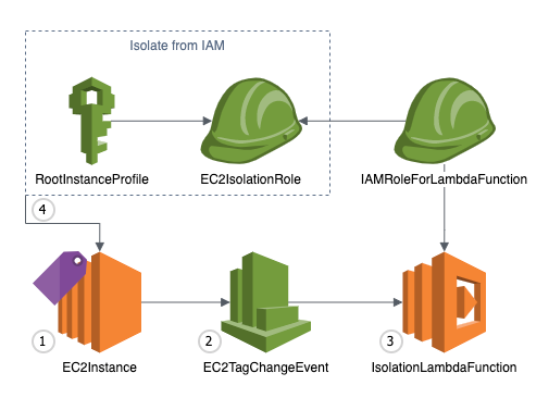
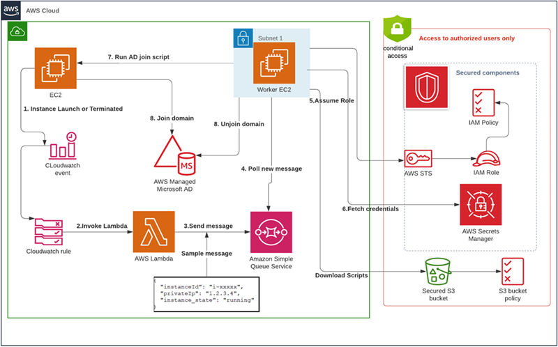
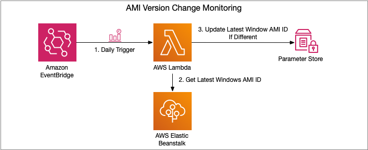
Figure 1: High-level diagram showing event flow
- AWS Batch uses an Amazon EC2 Compute Environment powered by Amazon ECS. This compute environment uses a custom EC2 Launch Template to configure the Amazon ECS agent to include credentials for pulling images from private registries.
- An EC2 User Data script is run upon EC2 instance startup that retrieves registry credentials from AWS Secrets Manager. The EC2 instance authenticates with AWS Secrets Manager using its configured IAM instance profile, which grants temporary IAM credentials.
- AWS Batch jobs can be submitted using private images that require authentication with configured credentials.
Prerequisites
For this walkthrough, you should have the following prerequisites:
- An AWS account
- An Amazon Virtual Private Cloud with private and public subnets. If you do not have a VPC, this tutorial can be followed. The AWS Batch compute environment must have connectivity to the container registry.
- A container registry containing a private image. This example uses Docker Hub and assumes you have created a private repository
- Registry credentials and/or an access token to authenticate with the container registry or Docker Hub.
- A VPC Security Group allowing the AWS Batch compute environment egress connectivity to the container registry.
A CloudFormation template is provided to simplify setting up this example. The CloudFormation template and provided EC2 user data script can be viewed here on GitHub.
The CloudFormation template will create the following resources:
- Necessary IAM roles for AWS Batch
- AWS Secrets Manager secret containing container registry credentials
- AWS Batch managed compute environment and job queue
- EC2 Launch Configuration with user data script
Click the Launch Stack button to get started:
![]()
Launch the CloudFormation stack
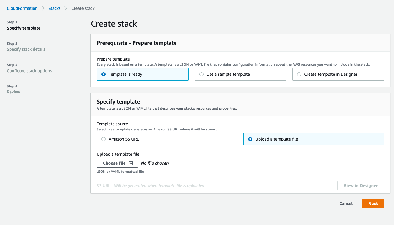
After clicking the Launch stack button above, click Next to be presented with the following screen:

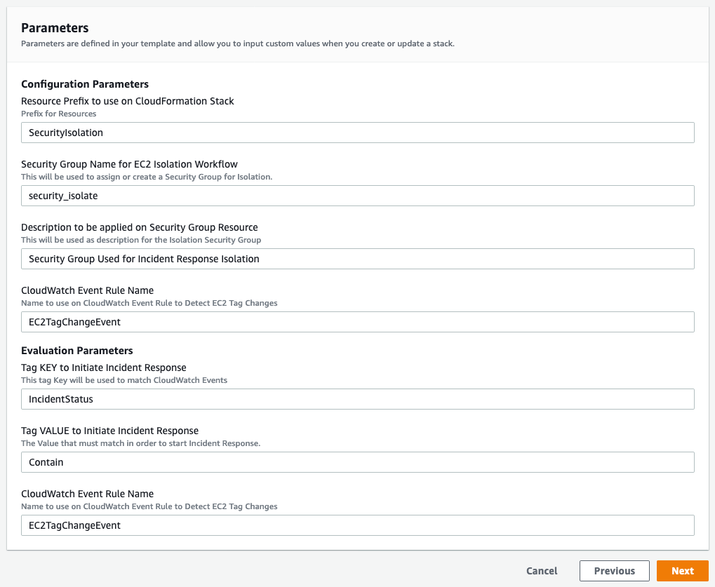
Figure 2: CloudFormation stack parameters
Fill in the required parameters as follows:
- Stack Name: Give your stack a unique name.
- Password: Your container registry password or Docker Hub access token. Note that both user name and password are masked and will not appear in any CF logs or output. Additionally, they are securely stored in an AWS Secrets Manager secret created by CloudFormation.
- RegistryUrl: If not using Docker Hub, specify the URL of the private container registry.
- User name: Your container registry user name.
- SecurityGroupIDs: Select your previously created security group to assign to the example Batch compute environment.
- SubnetIDs: To assign to the example Batch compute environment, select one or more VPC subnet IDs.
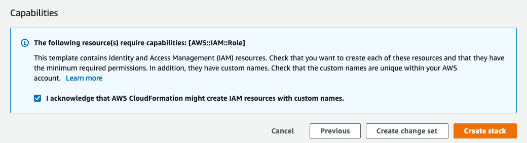
After entering these parameters, you can click through next twice and create the stack, which will take a few minutes to complete. Note that you must acknowledge that the template creates IAM resources on the review page before submitting.
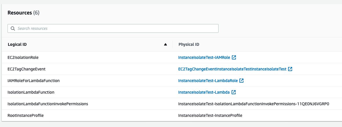
Finally, you will be presented with a list of created AWS resources once the stack deployment finishes as shown in Figure 3 if you would like to dig deeper.

Figure 3: CloudFormation created resources
User data script contained within launch template
AWS Batch allows you to customize the compute environment in a variety of ways such as specifying an EC2 key pair, custom AMI, or an EC2 user data script. This is done by specifying an EC2 launch template before creating the Batch compute environment. For more information on Batch launch template support, see here.
Let’s take a closer look at how the Amazon ECS agent is configured upon compute environment startup to use your registry credentials.
This example script uses and installs a few tools including the AWS CLI and the open-source tool jq to retrieve and parse the previously created Secrets Manager secret. These packages are installed using the cloud-config user data type, which is part of the cloud-init packages functionality. If using the provided CloudFormation template, this script will be dynamically rendered to reference the created secret, but note that you must specify the correct Secrets Manager secret id if not using the template.
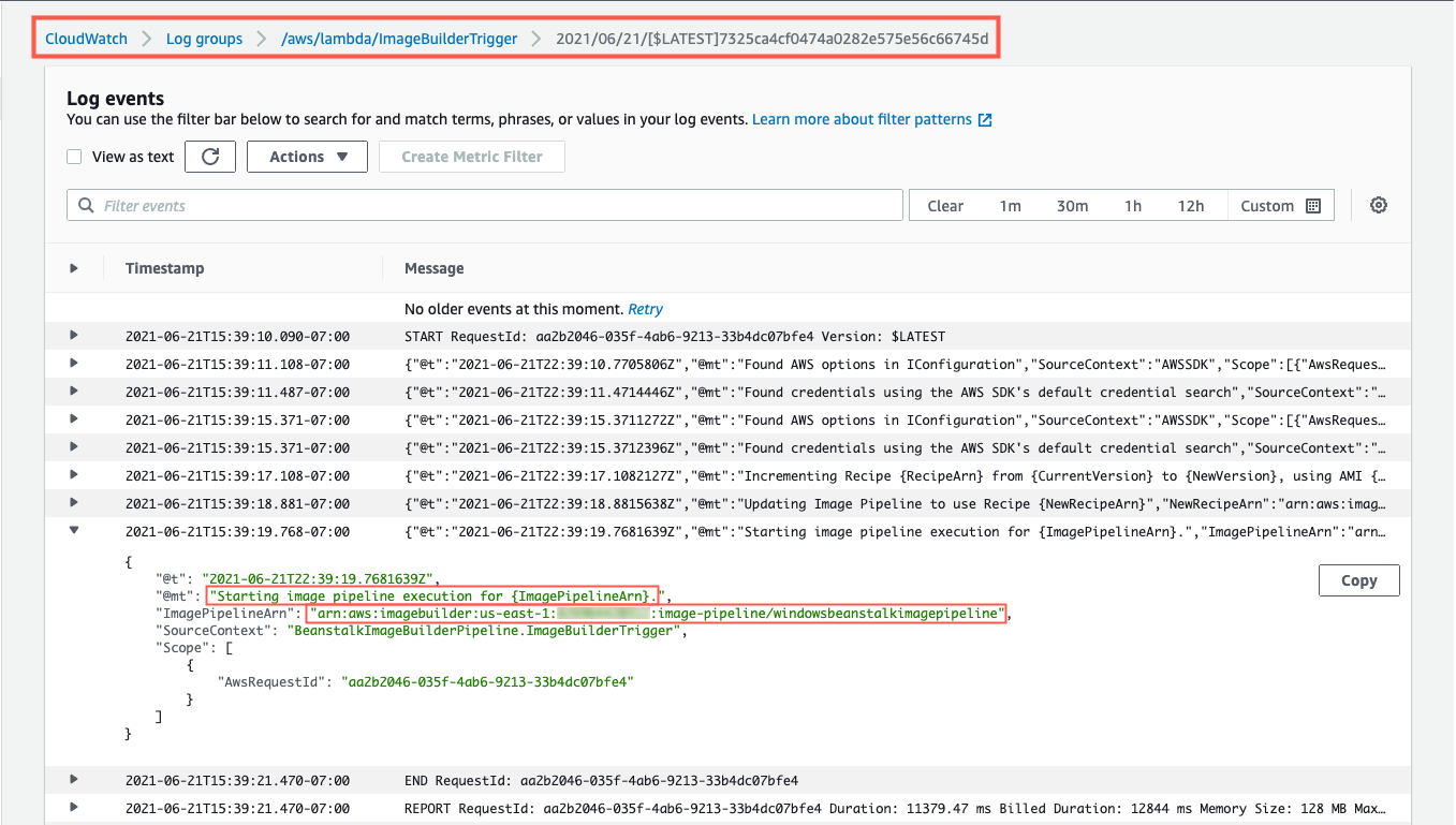
After performing a Docker login, the generated Auth JSON object is captured and passed to the Amazon ECS agent configuration to be used on AWS Batch jobs that require private images. For an explanation of Amazon ECS agent configuration options including available Amazon ECS engine Auth types, see here. This example script can be extended or customized to fit your needs but must adhere to requirements for Batch launch template user data scripts, including being in MIME multi-part archive format.
It’s worth noting that the AWS CLI automatically grabs temporary IAM credentials from the associated IAM instance profile the CloudFormation stack created in order to retrieve the Secret Manager secret values. This example assumes you created the AWS Secrets Manager secret with the default AWS managed KMS key for Secrets Manager. However, if you choose to encrypt your secret with a customer managed KMS key, make sure to specify kms:Decrypt IAM permissions for the Batch compute environment IAM role.
Submitting the AWS Batch job
Now let’s try an example Batch job that uses a private container image by creating a Batch job definition and submitting a Batch job:
- Open the AWS Batch console
- Navigate to the Job Definition page
- Click create
- Provide a unique Name for the job definition
- Select the EC2 platform
- Specify your private container image located in the Image field
- Click create

Figure 4: Batch job definition
Now you can submit an AWS Batch job that uses this job definition:
- Click on the Jobs page
- Click Submit New Job
- Provide a Name for the job
- Select the previously created job definition
- Select the Batch Job Queue created by the CloudFormation stack
- Click Submit
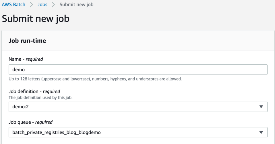
Figure 5: Submitting a new Batch job
After submitting the AWS Batch job, it will take a few minutes for the AWS Batch Compute Environment to create resources for scheduling the job. Once that is done, you should see a SUCCEEDED status by viewing the job and filtering by AWS Batch job queue shown in Figure 6.

Figure 6: AWS Batch job succeeded
Cleaning up
To clean up the example resources, click delete for the created CloudFormation stack in the CloudFormation Console.
Conclusion
In this blog, you deployed a customized AWS Batch managed compute environment that was configured to allow pulling private container images in a secure manner. As I’ve shown, AWS Batch gives you the flexibility to use both private and public container registries. I encourage you to continue to explore the many options available natively on AWS for hosting and pulling container images. Amazon ECR or the recently launched Amazon ECR public repositories (for a deeper dive, see this blog announcement) both provide a seamless experience for container workloads running on AWS.


 For more information, see


 Our initial customers saw the value right away and started to put EC2 to use in many different ways. We hosted web sites,