Tag Archives: AWS

Snaring the Bad Folks

Post Syndicated from Netflix Technology Blog original https://netflixtechblog.com/snaring-the-bad-folks-66726a1f4c80

Project by Netflix’s Cloud Infrastructure Security team (Alex Bainbridge, Mike Grima, Nick Siow)

Cloud security is a hard problem, but an even harder one is cloud security at scale. In recent years we’ve seen several cloud focused data breaches and evidence shows that threat actors are becoming more advanced with their techniques, goals, and tooling. With 2021 set to be a new high for the number of data breaches, it was plainly evident that we needed to evolve how we approach our cloud infrastructure security strategy.

In 2020, we decided to reinvent how we handle cloud security findings by redefining how we write and respond to cloud detections. We knew that given our scale, we needed to rely heavily on automations and that we needed to build our solutions using battle tested scalable infrastructure.

Introducing Snare

Snare Logo

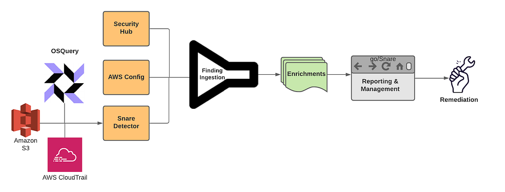
Snare is our Detection, Enrichment, and Response platform for handling cloud security related findings at Netflix. Snare is responsible for receiving millions of records a minute, analyzing, alerting, and responding to them. Snare also provides a space for our security engineers to track what’s going on, drill down into various findings, follow their investigation flow, and ensure that findings are reaching their proper resolution. Snare can be broken down into the following parts: Detection, Enrichment, Reporting & Management, and Remediation.

Snare Finding Lifecycle

Overview

Snare was built from the ground up to be scalable to manage Netflix’s massive scale. We currently process tens of millions of log records every minute and analyze these events to perform in-house custom detections. We collect findings from a number of sources, which includes AWS Security Hub, AWS Config Rules, and our own in-house custom detections. Once ingested, findings are then enriched and processed with additional metadata collected from Netflix’s internal data sources. Finally, findings are checked against suppression rules and routed to our control plane for triaging and remediation.

Where We Are Today

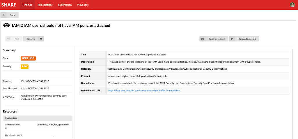
We’ve developed, deployed, and operated Snare for almost a year, and since then, we’ve seen tremendous improvements while handling our cloud security findings. A number of findings are auto remediated, others utilize slack alerts to loop in the oncall to triage via the Snare UI. One major improvement was a direct time savings for our detection squad. Utilizing Snare, we were able to perform more granular tuning and aggregation of findings leading to an average of 73.5% reduction in our false positive finding volume across our ingestion streams. With this additional time, we were able to focus on new detections and new features for Snare.

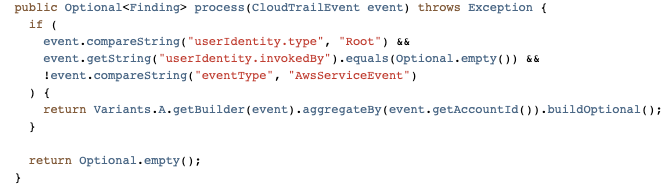
Speaking of new detections, we’ve more than doubled the number of our in-house detections, and onboarded several detection solutions from security vendors. The Snare framework enables us to write detections quickly and efficiently with all of the plumbing and configurations abstracted away from us. Detection authors only need to be concerned with their actual detection logic, and everything else is handled for them.

Simple Snare Root User Detection

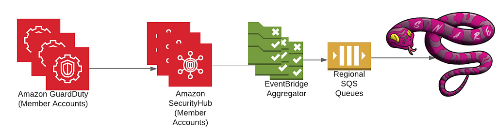
As for security vendors, we’ve most notably worked with AWS to ensure that services like GuardDuty and Security Hub are first class citizens when it comes to detection sources. Integration with Security Hub was a critical design decision from the start due to the high amount of leverage we get from receiving all of the AWS Security findings in a normalized format and in a centralized location. Security Hub has played an integral role in our platform, and made evaluations of AWS security services and new features easy to try out and adopt. Our plumbing between Security Hub and Snare is managed through AWS Organizations as well as EventBridge rules deployed in every region and account to aid in aggregating all findings into our centralized Snare platform.

High Level Security Service Plumbing
Example AWS Security Finding from our testing/sandbox account In Snare UI

One area that we are investing heavily is our automated remediation potential. We’ve explored a few different options ranging from fully automated remediations, manually triggered remediations, as well as automated playbooks for additional data gathering during incident triage. We decided to employ AWS Step Functions to be our execution environment due to the unique DAGs we could build and the simplistic “wait”/”task token” functionality, which allows us to involve humans when necessary for approval/input.

Building on top of step functions, we created a 4 step remediation process: pre-processing, decision, remediation, and post-processing. Pre/post processing can be used for managing out-of-band resource checks, or any work that needs to be done in order to ensure a successful remediation. The decision step is used to perform a final pre-flight check before remediation. This can involve a human reachout, verifying the resource is still around, etc. The remediation step is where we perform our actual remediation. We’ve been able to use this to a great deal of success with infrastructure-wide misconfigured resources being automatically fixed near real time, and enabling the creation of new fully automated incident response playbooks. We’re still exploring new ways we might be able to use this, and are excited for how we might evolve our approach in the near future.

Step Function DAG for S3 Public Access Block Remediation

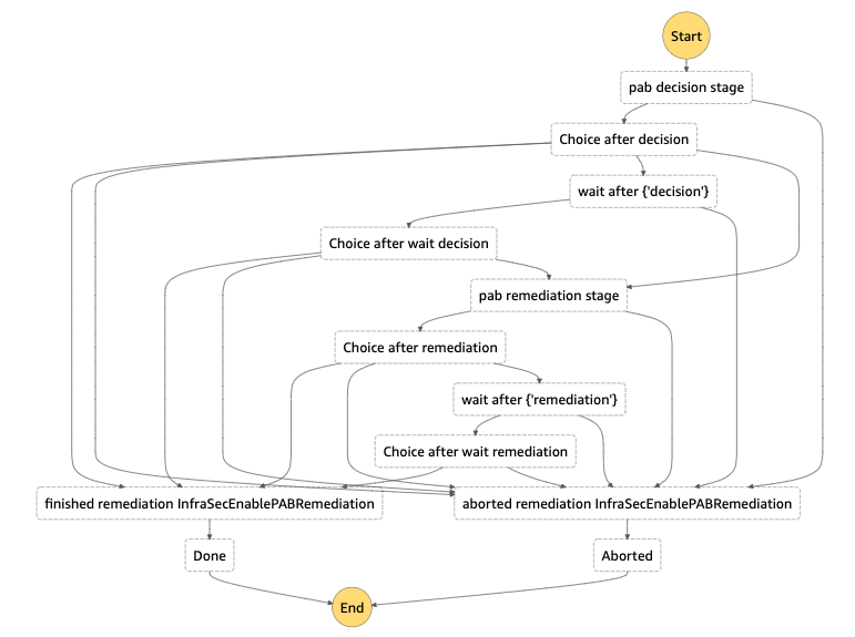
Diagram from a remediation to enable S3’s public access block on a non-compliant bucket. Each choice stage allows for dynamic routing to a variety of different stages based on the output of the previous function. Wait stages are used when human intervention/approval is needed.

Extensible Learnings

We’ve come a long way in our journey, and we’ve had numerous learning opportunities that we wanted to collect and share. Hopefully, we’ve made the mistakes and learned from those experiences.

Information is Key

Home grown context and metadata streams are invaluable for a detection and response program. By uniting detections and context, you’re able to unlock a new world of possibilities for reducing false positives, creating new detections that rely on business specific context, and help better tailor your severities and automated remediation decisions based on your desired risk appetite. A common theme we’ve often encountered is the need to bring additional context throughout various stages of our pipeline, so make sure to plan for that from the get-go.

Step Functions for Remediations

Step functions provide a highly extensible and unique platform to create remediations. Utilizing the AWS CDK, we were able to build a platform to enable us to easily roll out new remediations. While creating our remediation platform, we explored SSM Automation Runbooks. While SSM Automation Runbooks have great potential for remediating simple issues, we found they weren’t flexible enough to cover a wide spread of our needs, nor did they offer some of the more advanced features we were looking for such as reaching out to humans. Step functions gave us the right amount of flexibility, control, and ease of use in order to be a great asset for the Snare platform.

Closing Thoughts

We’ve come a long way in a year, and we still have a number of interesting things on the horizon. We’re looking at continuing to create new, more advanced features and detections for Snare to reduce cloud security risks in order to keep up with all of the exciting things happening here at Netflix. Make sure to check out some of our other recent blog posts!

Special Thanks

Special thanks to everyone who helped to contribute and provide feedback during the design and implementation of Snare. Notably Shannon Morrison, Sapna Solanki, Jason Schroth from our partner team Detection Engineering, as well as some of the folks from AWS — Prateek Sharma & Ely Kahn. Additional thanks to the rest of our Cloud Infrastructure Security team (Hee Won Kim, Joseph Kjar, Steven Reiling, Patrick Sanders, Srinath Kuruvadi) for their support and help with Snare features, processes, and design decisions!


Snaring the Bad Folks was originally published in Netflix TechBlog on Medium, where people are continuing the conversation by highlighting and responding to this story.

How to set up Amazon Quicksight dashboard for Amazon Pinpoint and Amazon SES engagement events

Post Syndicated from satyaso original https://aws.amazon.com/blogs/messaging-and-targeting/how-to-set-up-amazon-quicksight-dashboard-for-amazon-pinpoint-and-amazon-ses-events/

In this post, we will walk through using Amazon Pinpoint and Amazon Quicksight to create customizable messaging campaign reports. Amazon Pinpoint is a flexible and scalable outbound and inbound marketing communications service that allows customers to connect with users over channels like email, SMS, push, or voice. Amazon QuickSight is a scalable, serverless, embeddable, machine learning-powered business intelligence (BI) service built for the cloud. This solution allows event and user data from Amazon Pinpoint to flow into Amazon Quicksight. Once in Quicksight, customers can build their own reports that shows campaign performance on a more granular level.

Engagement Event Dashboard

Customers want to view the results of their messaging campaigns in ever increasing levels of granularity and ensure their users see value from the email, SMS or push notifications they receive. Customers also want to analyze how different user segments respond to different messages, and how to optimize subsequent user communication. Previously, customers could only view this data in Amazon Pinpoint analytics, which offers robust reporting on: events, funnels, and campaigns. However, does not allow analysis across these different parameters and the building of custom reports. For example, show campaign revenue across different user segments, or show what events were generated after a user viewed a campaign in a funnel analysis. Customers would need to extract this data themselves and do the analysis in excel.

Prerequisites

  • Digital user engagement event database solution must be setup at 1st.
  • Customers should be prepared to purchase Amazon Quicksight because it has its own set of costs which is not covered within Amazon Pinpoint cost.

Solution Overview

This Solution uses the Athena tables created by Digital user engagement events database solution. The AWS CloudFormation template given in this post automatically sets up the different architecture components, to capture detailed notifications about Amazon Pinpoint engagement events and log those in Amazon Athena in the form of Athena views. You still need to manually configure Amazon Quicksight dashboards to link to these newly generated Athena views. Please follow the steps below in order for further information.

Use case(s)

Event dashboard solutions have following use cases: –

  • Deep dive into engagement insights. (eg: SMS events, Email events, Campaign events, Journey events)
  • The ability to view engagement events at the individual user level.
  • Data/process mining turn raw event data into useful marking insights.
  • User engagement benchmarking and end user event funneling.
  • Compute campaign conversions (post campaign user analysis to show campaign effectiveness)
  • Build funnels that shows user progression.

Getting started with solution deployment

Prerequisite tasks to be completed before deploying the logging solution

Step 1 – Create AWS account, Pinpoint Project, Implement Event-Database-Solution.
As part of this step customers need to implement DUE Event database solution as the current solution (DUE event dashboard) is an extension of DUE event database solution. The basic assumption here is that the customer has already configured Amazon Pinpoint project or Amazon SES within the required AWS region before implementing this step.

The steps required to implement an event dashboard solution are as follows.

a/Follow the steps mentioned in Event database solution to implement the complete stack. Prior installing the complete stack copy and save the name Athena events database name as shown in the diagram. For my case it is due_eventdb. Database name is required as an input parameter for the current Event Dashboard solution.

b/Once the solution is deployed, navigate to the output page of the cloud formation stack, and copy, and save the following information, which will be required as input parameters in step 2 of the current Event Dashboard solution.

Step 2 – Deploy Cloud formation template for Event dashboard solution
This step generates a number of new Amazon Athena views that will serve as a data source for Amazon Quicksight. Continue with the following actions.

  • Download the cloud formation template(“Event-dashboard.yaml”) from AWS samples.
  • Navigate to Cloud formation page in AWS console, click up right on “Create stack” and select the option “With new resources (standard)”
  • Leave the “Prerequisite – Prepare template” to “Template is ready” and for the “Specify template” option, select “Upload a template file”. On the same page, click on “Choose file”, browse to find the file “Event-dashboard.yaml” file and select it. Once the file is uploaded, click “Next” and deploy the stack.

  • Enter following information under the section “Specify stack details”:
    • EventAthenaDatabaseName – As mentioned in Step 1-a.
    • S3DataLogBucket- As mentioned in Step 1-b
    • This solution will create additional 5 Athena views which are
      • All_email_events
      • All_SMS_events
      • All_custom_events (Custom events can be Mobile app/WebApp/Push Events)
      • All_campaign_events
      • All_journey_events

Step 3 – Create Amazon Quicksight engagement Dashboard
This step walks you through the process of creating an Amazon Quicksight dashboard for Amazon Pinpoint engagement events using the Athena views you created in step-2

  1. To Setup Amazon Quicksight for the 1st time please follow this link (this process is not needed if you have already setup Amazon Quicksight). Please make sure you are an Amazon Quicksight Administrator.
  2. Go/search Amazon Quicksight on AWS console.
  3. Create New Analysis and then select “New dataset”
  4. Select Athena as data source
  5. As a next step, you need to select what all analysis you need for respective events. This solution provides option to create 5 different set of analysis as mentioned in Step 2. They are a/All email events, b/All SMS Events, c/All Custom Events (Mobile/Web App, web push etc), d/ All Campaign events, e/All Journey events. Dashboard can be created from Quicksight analysis and same can be shared among the organization stake holders. Following are the steps to create analysis and dashboards for different type of events.
  6. Email Events –
    • For all email events, name the analysis “All-emails-events” (this can be any kind of customer preferred nomenclature), select Athena workgroup as primary, and then create a data source.
    • Once you create the data source Quicksight lists all the views and tables available under the specified database (in our case it is:-  due_eventdb). Select the email_all_events view as data source.
    • Select the event data location for analysis. There are mainly two options available which are a/ Import to Spice quicker analysis b/ Directly query your data. Please select the preferred options and then click on “visualize the data”.
    • Import to Spice quicker analysis – SPICE is the Amazon QuickSight Super-fast, Parallel, In-memory Calculation Engine. It’s engineered to rapidly perform advanced calculations and serve data. In Enterprise edition, data stored in SPICE is encrypted at rest. (1 GB of storage is available for free for extra storage customer need to pay extra, please refer cost section in this document )
    • Directly query your data – This process enables Quicksight to query directly to the Athena or source database (In the current case it is Athena) and Quicksight will not store any data.
    • Now that you have selected a data source, you will be taken to a blank quick sight canvas (Blank analysis page) as shown in the following Image, please drag and drop what visualization type you need to visualize onto the auto-graph pane. Please note that Amazon QuickSight is a Busines intelligence platform, so customers are free to choose the desired visualization types to observe the individual engagement events.
    • As part of this blog, we have displayed how to create some simple analysis graphs to visualize the engagement events.
    • As an initial step please Select tabular Visualization as shown in the Image.
    • Select all the event dimensions that you want to put it as part of the Table in X axis. Amazon Quicksight table can be extended to show as many as tables columns, this completely depends upon the business requirement how much data marketers want to visualize.
    • Further filtering on the table can be done using Quicksight filters, you can apply the filter on specific granular values to enable further filtering. For Eg – If you want to apply filtering on the destination email Id then 1/Select the filter from left hand menu 2/Add destination field as the filtering criterion 3/ Tick on the destination field you are trying to filter or search for the Destination email ID that 4/ All the result in the table gets further filtered as per the filter criterion
    • As a next step please add another visual from top left corner “Add -> Add Visual”, then select the Donut Chart from Visual types pane. Donut charts are always used for displaying aggregation.
    • Then select the “event_type” as the Group to visualize the aggregated events, this helps marketers/business users to figure out how many email events occurred and what are the aggregated success ratio, click ratio, complain ratio or bounce ratio etc for the emails/Campaign that’s sent to end users.
    • To create a Quicksight dashboards from the Quicksight analysis click Share menu option at the top right corner then select publish dashboard”. Provide required dashboard name while publishing the dashboard”. Same dashboard can be shared with multiple audiences in the Organization.
    • Following is the final version of the dashboard. As mentioned above Quicksight dashboards can be shared with other stakeholders and also complete dashboard can be exported as excel sheet.
  7. SMS Events-
    • As shown above SMS events can be analyzed using Quicksight and dash boards can be created out of the analysis. Please repeat all of the sub-steps listed in step 6. Following is a sample SMS dashboard.
  8. Custom Events-
    • After you integrate your application (app) with Amazon Pinpoint, Amazon Pinpoint can stream event data about user activity, different type custom events, and message deliveries for the app. Eg :- Session.start, Product_page_view, _session.stop etc. Do repeat all of the sub-steps listed in step 6 create a custom event dashboards.
  9. Campaign events
    • As shown before campaign also can be included in the same dashboard or you can create new dashboard only for campaign events.

Cost for Event dashboard solution
You are responsible for the cost of the AWS services used while running this solution. As of the date of publication, the cost for running this solution with default settings in the US West (Oregon) Region is approximately $65 a month. The cost estimate includes the cost of AWS Lambda, Amazon Athena, Amazon Quicksight. The estimate assumes querying 1TB of data in a month, and two authors managing Amazon Quicksight every month, four Amazon Quicksight readers witnessing the events dashboard unlimited times in a month, and a Quicksight spice capacity is 50 GB per month. Prices are subject to change. For full details, see the pricing webpage for each AWS service you will be using in this solution.

Clean up

When you’re done with this exercise, complete the following steps to delete your resources and stop incurring costs:

  1. On the CloudFormation console, select your stack and choose Delete. This cleans up all the resources created by the stack,
  2. Delete the Amazon Quicksight Dashboards and data sets that you have created.

Conclusion

In this blog post, I have demonstrated how marketers, business users, and business analysts can utilize Amazon Quicksight dashboards to evaluate and exploit user engagement data from Amazon SES and Pinpoint event streams. Customers can also utilize this solution to understand how Amazon Pinpoint campaigns lead to business conversions, in addition to analyzing multi-channel communication metrics at the individual user level.

Next steps

The personas for this blog are both the tech team and the marketing analyst team, as it involves a code deployment to create very simple Athena views, as well as the steps to create an Amazon Quicksight dashboard to analyse Amazon SES and Amazon Pinpoint engagement events at the individual user level. Customers may then create their own Amazon Quicksight dashboards to illustrate the conversion ratio and propensity trends in real time by integrating campaign events with app-level events such as purchase conversions, order placement, and so on.

Extending the solution

You can download the AWS Cloudformation templates, code for this solution from our public GitHub repository and modify it to fit your needs.


About the Author


Satyasovan Tripathy works at Amazon Web Services as a Senior Specialist Solution Architect. He is based in Bengaluru, India, and specialises on the AWS Digital User Engagement product portfolio. He likes reading and travelling outside of work.

InsightCloudSec Supports 12 New AWS Services Announced at re:Invent

Post Syndicated from Chris DeRamus original https://blog.rapid7.com/2021/12/06/insightcloudsec-supports-12-new-aws-services-announced-at-re-invent/

InsightCloudSec Supports 12 New AWS Services Announced at re:Invent

In case you didn’t hear, Amazon hosted AWS re:Invent in Las Vegas last week. As has come to be expected at the annual mega-event, Amazon made a number of huge announcements and launched a significant number of improvements and brand-new services and settings to enhance their public cloud platform, including an improved version of Amazon Inspector, S3 Object Ownership, Recycle Bin, EBS Archive Mode, and more.

Along with these announcements comes plenty of excitement and fanfare from the developer community who gets to take advantage of the new functionality. And that excitement is warranted. But these announcements also usually come with a hint of hesitation from their colleagues in security, who are responsible for analyzing all of these new services and settings to ensure that they are used properly and don’t introduce unintended consequences to their AWS environment. Yes, security is a factor here, but those unintended consequences also include costs associated with rolling out these new services. Rightfully so: It can often take weeks or months for organizations to vet these services, define governance policies, and actually start taking advantage of them.

But in order to help extinguish some of that announcement-induced anxiety and allow our customers to start taking advantage of these services as quickly as possible, the InsightCloudSec team has worked day and night for the last week to deliver support for a dozen of the new services that AWS rolled out last week.

In all of these cases, InsightCloudSec gathers the data related to these services across all AWS accounts and regions and consolidates it, giving security teams a single place to see all of the information across the entire AWS footprint. In many cases, the support also enhances the services provided by Amazon by providing additional context about the service or the resources associated with it.

Rather than choosing between slowing down innovation or taking on unmitigated risk, our customers will have the ability to take full advantage of each of these services as soon as they are available.

The list of newly supported AWS services and services includes:

Let’s take a look at a few of the most critical services and what they mean for DevOps and Security teams.

The new AWS Inspector

Amazon Inspector is a vulnerability management service that continually scans AWS workloads for software vulnerabilities and unintended network exposure. As an AWS-built service, Amazon Inspector is designed to exchange data and interact with other core AWS services not only to identify potential security findings, but also to automate addressing those findings.

By joining insights from both AWS Inspector and Rapid7, customers benefit from immediate value in the form of multiple enhancements across the board. These include enhanced risk assessment of containers and workloads, unified visibility and control, and robust context across AWS environments.

By consolidating AWS’s vulnerability management solutions with Rapid7’s cloud security capabilities, organizations are enabled with a ​​highly scalable service, equipped with optimized security controls to better handle their most valuable assets.

InsightCloudSec seamlessly complements the new and improved AWS Inspector, allowing customers to leverage enhanced capabilities including:

  • Identify regions, accounts, and compute instances where AWS Inspector is not enabled, along with a new bot action to turn on the capability across EC2/ECR
  • Identify compute resources by risk score and/or specific findings
  • Identify accounts and regions with the highest overall risk
  • Add Inspector as an agent type so customers can switch to the “Vulnerability View,” which provides a single pane of glass to view and naturally sort assets by risk/severity findings across their entire fleet of accounts
  • Use Inspector data to enrich existing Insights such as resources on a public subnet, resources with an IAM role attached, etc. to build new Insights (e.g., EC2 instance on a public subnet with a security group exposing SSH that has been identified as high-risk by Inspector)

VPC Network Access Analyzer

Another great new service that Amazon rolled out is the Amazon VPC Network Access Analyzer, which helps their customers identify network configurations that lead to unintended network access. The tool essentially allows you to create a scope or query — for example, you could create a scope to find all web apps that do not use a firewall to access internet resources — then analyze your AWS account against that scope. It then serves up a list of the unexpected network paths between resources defined in the scope.

InsightCloudSec supports this new network analyzer by consuming all findings from the analyses our customers run in their entire AWS environment. This gives cloud security teams a single place to see all results, rather than having to jump from account to account to gather all the information across the entire AWS footprint. It also enriches the data provided by that network analysis with additional context about the resources, such as whether they have misconfigurations or overly permissive IAM policies attached to them, helping the user see the bigger picture and more effectively prioritize their work. Finally, the automation capabilities in InsightCloudSec allow our users to automatically schedule these network scans on a regular basis across target accounts, eliminating all manual effort.

S3 Object Ownership

The sheer scale of S3 makes access management a blind spot for a number of organizations. For years, customers who use S3 have had the ability to set object-level permissions, effectively superseding the access permissions established at the bucket level. While enhancements have been introduced over the years such as Block Public Access, which can help mitigate the chance of objects being made public via direct Access Control Lists (ACLs), not all customers leverage the capability. Amazon has gone a step further by introducing a capability known as S3 Object Ownership, which gives administrators the ability to completely disable object-level ACLs. This setting is now the default value on all newly created S3 buckets, and customers can now migrate their existing S3 buckets to leverage this capability.

InsightCloudSec now detects the presence of this capability and renders it in the product, as well as through the API response via the `Object Ownership` property. A new filter was created to identify S3 buckets based on the value of this property, and the team has also expanded the core Insight Storage Container Without Uniform Bucket Level Access to work across AWS, AWS GovCloud, and AWS China.

InsightCloudSec Supports 12 New AWS Services Announced at re:Invent

Recycle Bin

Data Lifecycle Management can be challenging as customer cloud footprints grow from dozens of cloud accounts to hundreds or even thousands. At InsightCloudSec we’ve seen customers with millions of EBS Snapshots across their fleet of accounts. While many of our customers have embraced AWS Backup to help centralize their backup and retention management, there’s always concern with the accidental removal of an important snapshot while performing cleanup operations across accounts.

AWS offers a new Recycle Bin service that can be used to reduce the risk of accidental deletion. Think of Recycle Bin in the same way that Recycle Bin operates on your own computer. When enabled, the capability will store snapshots for a period of time defined by the customer and allow them to be recovered. Customers define the length of time they’d like these snapshots to remain in the recycle bin before being permanently deleted.

InsightCloudSec now provides visibility into these Recycle Bin Rules directly within the Resources section of the product. We’ve also included filters to identify accounts/regions where snapshots exist and recycle bin rules are not in place. These filters can help InsightCloudSec customers continue to meet their evolving governance needs.

InsightCloudSec Supports 12 New AWS Services Announced at re:Invent

EBS Snapshot Archive

Going beyond Recycle Bin, AWS now offers a new archive mode storage class that, when enabled, can help customers reduce their storage costs. EBS Snapshot Archive is a new storage tier that is up to 75% cheaper than the standard storage tier. Converting to this tier is quite straightforward and can be done via the AWS Console or programmatic API.

To help our customers further reduce spend with this service, we’ve introduced visibility into this storage tier, along with a new filter and Bot action to help customers begin migrating to this new tier where applicable.

InsightCloudSec Supports 12 New AWS Services Announced at re:Invent

More to come

This is one of our team’s favorite weeks each year. It’s always great to see the new capabilities that the teams at Amazon have been hard at work on and how they take in customer feedback to mature their offering. The InsightCloudSec team will be introducing support for a number of these enhancements with our release this week (21.7.3) and will be working closely with our customers to add additional features and capabilities.

NEVER MISS A BLOG

Get the latest stories, expertise, and news about security today.

Deploying Zabbix in Amazon Web Services cloud platform

Post Syndicated from Arturs Lontons original https://blog.zabbix.com/deploying-zabbix-in-amazon-web-services-cloud-platform/17283/

With the rapid evolution and proliferation of different cloud services, many organizations have decided to move parts of their infrastructures from on-prem to cloud. As an essential part of your infrastructure, Zabbix is no exception – you always have the option to either deploy Zabbix on-prem or select from one of the many supported cloud service providers to deploy your Zabbix Server or Zabbix Proxy on.

In this blog post, let’s look at how we can quickly deploy Zabbix Server and Zabbix Proxy nodes in Amazon Web Services cloud platform.

Deploying the Zabbix Server in AWS

Let’s begin with the Zabbix download page. Under the Zabbix Cloud Images section, select the AWS cloud vendor and then the Cloud Image you wish to deploy. Let’s start with Zabbix Server 5.0 with MySQL DB backend and Nginx Web server backend for our frontend.

Next, we will be redirected to the AWS marketplace, where we will have to subscribe to the Zabbix Server 5.0 image.

Once we have subscribed to the Zabbix Server image, we can continue with the deployment configuration.

Next, we must select our Region, Zabbix minor version (usually the latest available), and the Fulfillment option. Once that is done, we can finalize the launch configuration.

Select the preferred Launch option, EC2 Instance Type, VPC, and Subent settings on the Launch page.

Next – We have to select or create a security group.

We also have to select or generate EC 2 Key pair – make sure to save your private key in a safe location!

Note that creating a security group based on seller settings does not guarantee that the group will have an inbound SSH access rule! Make sure to double-check the security group and manually add the SSH inbound rule if it hasn’t yet been added. We will need to access this instance via SSH to obtain the initial frontend login credentials!

Once you click on the Launch button, the deployment process for your Zabbix application will be initiated.

Accessing the application

Let’s open up the Instances section and open our newly deployed Zabbix instance

We can access the Zabbix Frontend by opening the Public IPv4 address or Public IPv4 DNS of the Zabbix instance

Note that the Zabbix frontend password is still unknown to us. Recall how I mention that we will need to access the instance via SSH to obtain the frontend password. Let’s do so now.

Write down the login credentials and use them to log in to the Zabbix instance.

Accessing the database

In case we wish to access the Zabbix database backend, we can do so from the command line. Zabbix database can be accessed by using the root user. By default, it can be used without a password.

The MySQL root password is stored in /root/.my.cnf configuration file.

Modifying the Zabbix Frontend timezone

By default, the Zabbix frontend uses the “UTC” timezone. If you need to change it, edit php_value[date.timezone] PHP variable in /etc/php-fpm.d/zabbix.conf and restart php-fpm process:

systemctl restart php-fpm

Zabbix proxy

If you wish to deploy a Zabbix proxy instance in your AWS cloud, the deployment steps are very much the same. Most likely, you will still require SSH access if you wish to perform some configuration changes in the Zabbix proxy configuration file.

Note, that by default, the SQLite proxy database is stored in /tmp/zabbix_proxy.sqlite3

As always, don’t forget the point the proxy at your Zabbix server instance by modifying the Server parameter in the Zabbix proxy configuration file, located in /etc/zabbix/zabbix_proxy.conf

And that’s all! With just a few clicks, we are able to deploy a fully functional Zabbix instance or a small Zabbix proxy to distribute or scale our monitoring. Don’t forget that AWS is just one of the many cloud service providers you can use with Official Zabbix images. If you have any questions about the AWS deployment – you are very much encouraged to leave a comment under this blog post.

If you wish to learn more about the Zabbix Monitoring solution, check out the official documentation https://www.zabbix.com/documentation/current/manual/quickstart.

Creating a costs analytics view to email campaign generated by Amazon Pinpoint

Post Syndicated from rafaaws original https://aws.amazon.com/blogs/messaging-and-targeting/creating-a-costs-analytics-view-to-email-campaign-generated-by-amazon-pinpoint/

Introduction

Many companies have multiple departments using different campaigns in the same AWS account on Amazon Pinpoint and need to split costs at the end of each month between the owners of each campaign. To do this, companies need an easy way to find how much each campaign has generated of cost, since the Amazon Pinpoint console doesn’t have this information. To solution this, it is possible combine some AWS services to find out these costs.

In this post, I will demonstrate how AWS analytics and storage services such as Amazon Kinesis, AWS Glue, Amazon Athena, Amazon Quicksight and Amazon Simple Storage Service (Amazon S3) can help you create an analytical view of the costs generated by emails sent through each campaign on Amazon Pinpoint. Not include transactional and Amazon Journey e-mails on the example.

Amazon Pinpoint is an AWS service that helps companies to engage their customers across multiple channels. You can use the Amazon Pinpoint to send email, SMS, push notifications and voice messages to deliver one-off demands or across campaigns.

In this blog, you will learn how to create a dashboard with total cost of emails sent and MTA (Monthly Targeted Audience) by each campaign. With this information, you will be able to distribute costs internally to each department responsible for each campaign on Amazon Pinpoint.

Solution Overview

To create this dashboard, we will take advantage of the Digital User Engagement Events Database solution. We can use an AWS CloudFormation template that set up Amazon Pinpoint event flow. This solution uses the Amazon Kinesis to stream all events about campaigns to a bucket on Amazon S3. After that, a data processing task is performed by AWS Lambda and cataloged on AWS Glue. Some views will be created on Amazon Athena to organize all data and we will use them to calculating and analyzing the Pinpoint costs. For more information about the solution, architecture and how AWS CloudFormation template works to automate the deployment, please visit the Implementation Guide page.

During the deployment process, you will have the option to create a new Amazon Pinpoint project to manage your campaigns or use an existing one.

Prerequisites

1. Complete the Digital User Engagement Events Database implementation.

2. Have an e-mail campaign on Amazon Pinpoint created with some emails already sent.

Analytics View

All events created by Amazon Pinpoint through the campaigns after the Digital Use Engagement Events Database implementation is complete should be appearing in parquet file format in the Amazon S3. If your campaign did not generate any events after the AWS CloudFormation was completed, I recommend creating and executing a new email campaign just to test this solution. Any test email sent during the implementation of this solution will incur charges. The email costs will be explained during this blog.

After the entire Amazon Pinpoint event flow has worked correctly, some modifications on the views created in Amazon Athena must be made. These changes will help to access the information about the quantity of endpoints registered by each campaign of your project. For this, the following steps are required:

To create a new view

1. Open the Amazon Athena console.

2. Under Database, choose the database name created by AWS CloudFormation template.

You will notice a table called “all events” and some views, eg. campaign_send, email_open, email_send and others. These views are responsible to improve the organization of data sent by Amazon Pinpoint, eg. in the campaign_send view it is possible to see all informations about all events that Amazon Pinpoint sends across the campaign by multiple channels.

3. Choose Create view.

A tab will be added on the center page so you can add your command which will be responsible to created a new view.

4. Replace the existing text to the command below and choose Run query.

CREATE OR REPLACE VIEW endpoint_unit AS
SELECT DISTINCT
client.client_id endpoint_id
, "min"("from_unixtime"((event_timestamp / 1000))) event_timestamp
, "month"("from_unixtime"((event_timestamp / 1000))) month_data
, "year"("from_unixtime"((event_timestamp / 1000))) year_data
FROM
all_events
WHERE (event_type = '_campaign.send')
GROUP BY client.client_id, "month"("from_unixtime"((event_timestamp / 1000))), "year"("from_unixtime"((event_timestamp / 1000)))

In this command we are creating a new view, grouping all the endpoints already used by campaigns, along with the earliest date and time that the endpoint was registered. This command will help you identify the first campaign that used the endpoint in each month and year.

Once the new view is created, you will notice that it is listed in the views pane with the name endpoint_unit. You can run this view to check which values are returned.

5. Choose Preview in the endpoint_unit view to return the results.

Example:

The data displayed refer only to the information of the endpoints used in campaigns after the implementation of the Digital User Engagement Events Database.

Now is the time to create the analytical view in Amazon Quicksight.

To check Amazon Quicksight Region

1. Open the Amazon Quicksight console.

If this is your first time using Amazon Quicksight, a page will appear to subscribe to the services, feel free to choose the best option for your business.

Warning: Some costs might occur by using Amazon Quicksight. Check the Amazon Quicksight Pricing page for more information.

2. On top of the screen, choose <Role>/<Account-Name> and select the region where you have the Amazon Pinpoint project.

To check Amazon Quicksight Permissions

Check the permission of the Amazon Quicksight to enable the access to Amazon S3 bucket.

1. On top of the screen, choose <Role>/<Account-Name>, Manage Quicksight.

2. In navigation pane, choose Security & permissions.

3. Under QuickSight access to AWS services, choose Add or remove.

4. Inside the QuickSight access to AWS services table, under Amazon S3, choose Details.

5. Choose Select S3 buckets.

6. Check if the Amazon S3 bucket name checkbox containing all stream files is selected. If not, select the checkbox and choose Finish and Update.

Create a Dataset for Campaign cost

1. Back to the Amazon Quicksight main page.

2. In the navigation page, choose Datasets, New dataset.

3. Choose Athena.

Now, let’s add the table containing information regarding the number of emails sent per Amazon Pinpoint campaign.

4. In the New Athena data source dialog box, do the following:

a. For Data source name, type a name.

b. Choose Create data source.

5. In the Choose your table dialog box, do the following:

a. Choose Use custom SQL.

b. In first field, enter a name for the custom SQL.

c. In second field, paste the command below.

SELECT * FROM "due_eventdb"."campaign_send" where (message_tags['delivery_type'] = 'EMAIL')

This command is filtering only events of campaign based on emails.

d. Choose Confirm query.

6. In the Finish dataset creation dialog box, you will be asked to select between storing a copy of the data of this table in SPICE or performing a query directly from data source. Feel free to choose the best option for your business.

7. Choose Visualize.

After creating the dataset, you will be redirected to the Amazon Quicksight analytics creation page.

As the information sent by Amazon Pinpoint does not have the unit cost of each email sent, we will use three features called Parameters, Control and Calculated Field to calculate these amounts.

Parameters are named variables that can transfer a value for use by an action or an object. To make the parameters accessible to the dashboard viewer, you add a parameter control.

The calculated fields help you to transform your data by using one or more of the actions: Operators, Functions, Aggregate functions, Fields that contain data or other calculated fields.

Create an Amazon QuickSight parameter

1. In the navigation bar, choose + Add at the top of the screen.

2. Choose Add parameter.

3. In the Create new parameter dialog box, do the following:

a. For Name, type the name for the parameter, eg. Costemail.

b. For Data type, choose number.

c. For Values, select Single value.

d. For Static default value enter the unit cost of email. The cost of each Amazon Pinpoint email can be found on Amazon Pinpoint Pricing page.

e. Choose Create and Close.

Important: All costs in this blog will be calculated in USD.

After creating the first parameters, we need to create a manual control of these costs.

Create an Amazon QuickSight control

1. In the navigation pane, choose Parameters.

2. Under the name of parameters that you previously created, choose Add control.

3.  In the Add control dialog box, do the following:

a. For Display name, enter a name.

b. For Style, choose Text field.

c. Choose Add.

This control will help you in the future if you need to change the unit price without changing the Parameters configuration.

We now need to create the Calculate Field. It multiplying the total sent emails value by the unit costs.

Create an Amazon QuickSight calculated field

1. In the navigation bar, choose + Add at the top of the screen again.

2. Choose add calculated field.

3. In add name field, type a name.

4. Paste the expression below.

count({pinpoint_campaign_id}) * ${name_parameters}

5. Replace the “name_parameters” in the expression with the name of the Parameter you created earlier.

6. Choose Save.

We now have all fields available to create the chart on Quicksight.

Create an Amazon QuickSight dashboard

1. In the navigation page, choose Visualize.

2. Under Visual type, choose Vertical bar chart.

Note: If you prefer, you can change it later to other visual type.

3. Choose the fields pinpoint_campaign_id, calculated field that you just created and event_timestamp. Drag each field to X axis, value and group/color to create the chart.

Example:

In this example, you can see the cost in USD x Amazon Pinpoint Campaign ID between April and May 2021.

If you prefer, you can customize your chart in Format Visual. You can also build another view to show the amount of emails sent per campaign.

4. In the navigation bar, choose Share.

5. Choose Publish dashboard.

6. In the Publish a dashboard dialog box, under Publish new dashboard as, type a name.

7. Choose Publish dashboard.

If you want, you can share your dashboard with other username, group, or email address.

Now that we have the total costs of emails per each campaign, let’s create the chart for the total endpoint cost for each campaign.

Create a Dataset for MTA cost

1. Back to the Amazon Quicksight main page.

2. In the navigation page, choose Datasets, New dataset.

3. Choose Athena.

4. In the New Athena data source dialog box, do the following:

a. For Data source name, type a name.

b. Choose Create data source.

5. In the Choose your table dialog box, do the following:

a. Choose Use custom SQL.

b. In first field, enter a name for the custom SQL.

c. In second field, paste the command below.

SELECT distinct c.endpoint_id, e.pinpoint_campaign_id, c.event_timestamp
FROM "due_eventdb"."campaign_send" e
INNER JOIN "due_eventdb"."endpoint_unit" c ON c.event_timestamp = e.event_timestamp

d. Choose Confirm query.

6. In the Finish dataset creation dialog box, you will be asked to select between storing a copy of the data of this table in SPICE or performing a query directly from data source. Feel free to choose the best option for your business.

7. Choose Visualize.

This command is responsible to join the pinpoint_campaign view with the endpoint_unit view. This command will return the campaign ID responsible for contacting the endpoint for the first time on each month.

8. After the dataset is created, repeat the same steps to create a new Parameter, Control and Calculated Field on section Create an Amazon QuickSight parameter, Create an Amazon QuickSight control and Create an Amazon QuickSight calculated field, but when creating a new Parameter, you will use the unit cost of each endpoint, currently it is described on the Amazon Pinpoint Pricing page as Monthly Targeted Audience (MTA).

If you send messages from an Amazon Pinpoint campaign or journey, the unique endpoints you contact are known as a monthly targeted audience (MTA). You are charged on the number of MTAs targeted in a calendar month.

Important: In this calculation we are not considering the subtraction of the free tier values.

In the process of creating Calculated Field, use the following expression:

count({endpoint_id}) * ${name_parameters}

Also remember to replace the name_parameters field in the expression with the name of the parameter that you previously created in point 8 on Create a Dataset for MTA cost section to calculate the costs of endpoints.
In this expression you are calculating the MTA for the distinct endpoint contacted per month.

After this, you will also have all the required fields to create your total cost chart of endpoint per campaign. In this case, use the fields pinpoint_campaign_id, calculated field that you created earlier and event_timestamp.

Example:

In this example, you can see the MTA cost in USD x Amazon Pinpoint Campaign ID between April and May 2021.

Some customers usually have tens or hundreds of campaigns, on this case you can use the Filter option in the navigation pane to a specify a range of date.

Optional: If you prefer you can combine the email and MTA cost in the same Analyses and Dashboard.

Add more datasets in the same Analyses and Dashboard

1. Back to the Amazon Quicksight main page.

2. In the navigation page, choose Analyses.

3. Choose the email cost Analyses that you created on section Create an Amazon QuickSight dashboard.

4. Choose the pencil icon on Dataset option near to the Navigation page.

5. Choose add dataset.

6. In the Choose dataset to add dialog box, choose the dataset you created on section Create a Dataset for MTA cost.

7. Choose Select.

Now you can create each parameter, control and calculated field per dataset on the same Analyses and publish all charts on same dashboard.

Cleanup

To avoid incurring charges, navigate to AWS Cloudformation console and delete the stack that you used on Digital User Engagement Events Database solutions procedure.

After the stack is deleted, you also need to delete your dashboards, analyses and datasets on Amazon Quicksight. You can also delete the stream events data in your Amazon S3 bucket.

Conclusion

In this blog, we used the total cost of email sent and endpoints to create the charts, but it is possible to obtain several analyses in Quicksight using the views that became available in the Digital User Engagement Events Database solution, such as costs for push notifications and other types of channels.

Also try creating dashboards with other Amazon Pinpoint channels

To do this, use this same procedure, explore the view campaign_send to find all data about other channels and modify the SQL queries on Amazon Quicksight to create your dashboards.


About the Author

Rafael Rodrigues is an Enterprise Solution Architect for AWS based in Sao Paulo, Brazil. He helps customers innovate with modern IT architecture on cloud computing.

Amazon Simple Email Service Celebrates 50 Years of Email

Post Syndicated from Matt Strzelecki original https://aws.amazon.com/blogs/messaging-and-targeting/amazon-simple-email-service-celebrates-50-years-of-email/

Email as we know it turns 50 years old this month (October 2021). The first email sent over a network — the beginning of email as we use it today — was sent in October 1971, by MIT graduate Ray Tomlinson (April 23, 1941–March 5, 2016). Tomlinson was the first to use the @ symbol to identify a message recipient on a remote computer system. Using this address format, he became the first person to send an email between two computers. That first email traveled 10 feet between two computers in Cambridge, Massachusetts. Tomlinson stated when interviewed that the first email was “something like QWERTYUIOP”.

Tomlinson leveraged existing software at the time, including SNDMSG and CPYNET, which allowed people to send messages to others who used the same computer, to send the first email over a network – back then multiple users would share computers, rather than having their own dedicated computers. His work enabled the exchange of messages between computers for the first time. Creating email was a side project at work for Tomlinson, and when he showed his work to another employee for the first time, he reportedly said: “Don’t tell anyone! This isn’t what we’re supposed to be working on.”

Ray Tomlinson was inducted into the Internet Hall of Fame in 2012, and his work is ranked fourth in Boston Globe’s top 150 MIT-related “Ideas, Inventions, and Innovators”.

According to the Guinness Book of Records, the first unsolicited email was sent in May 1978 to 397 recipients advertising an upcoming a product demonstration of computers. That’s right—spam is almost as old as email itself! In 1991, the first email was sent from space by astronauts on the NASA shuttle Atlantis. That message began with “Hello Earth!” and was delivered to Mission Control at the Johnson Space Center in Houston, Texas.

Over the past 50 years, there’s been a lot of firsts in email. For us at Amazon Simple Email Service (Amazon SES), our email first was when we launched our service back in January 2011. We initially started as a service that delivered email for Amazon.com, and grew over time into launching as a public service in Amazon Web Services (AWS).

Customers told us that building large-scale email solutions to send marketing and transactional messages was often a complex and costly challenge for businesses. Amazon SES eliminates these challenges and enables businesses to benefit from the years of experience and sophisticated email infrastructure Amazon.com has built to serve its own large-scale customer base. With Amazon.com being our first customer, from day one – scalability, reliability, and deliverability have been our highest priorities. This same service has also powered the email sending capabilities of Amazon Pinpoint since 2017, as well as email-related features in several other AWS services.

Today, Amazon SES is a cost-effective, flexible, and scalable email service that enables developers to send mail from within any application – supporting multiple email use cases, including transactional, marketing, or mass email communications, as well as inbound email.

We encourage our readers to share their own stories of their email firsts, or any other interesting email anecdotes. #QWERTYUIOP #50yrsofemail

Replace traditional email mailbox polling with real-time reads using Amazon SES and Lambda

Post Syndicated from agardezi original https://aws.amazon.com/blogs/messaging-and-targeting/replace-traditional-email-mailbox-polling-with-real-time-reads-using-amazon-ses-and-lambda/

Integrating emails into an automated workflow for automated processing can be challenging. Traditionally, applications have had to use the POP protocol to connect to mail servers and poll for emails to arrive in a mailbox and then process the messages inline and perform actions on the message. This can be an inefficient mechanism and prone to errors that result in the workflow missing messages. Since this method requires polling it’s not great if you need real-time processing of messages and introduces inefficiencies in the design. Amazon Simple Email Service (Amazon SES) is a cost effective, scalable and flexible email service with support for different workflows including the ability to perform spam checks and virus scans. In this blog you will see how to use Amazon SES with AWS Lambda and Amazon S3 in order to automate the processing of emails in real time and integrate with an application without the need for polling.

The use case explored in this blog focuses on automation for CRM or order processing platforms and processing of email related to customer contact or direct email requests. An example of this use case is copying a client engagement email to Salesforce (or any other database) where it is recorded and can later be categorized or attached to the appropriate client account or opportunity. When designing an application that needs to read emails from a mailbox, a developer would traditionally have to use a mail library (like JavaMail if using Java) to make a call to the mailbox, authenticate and then pull messages into an application object. This would mean polling the mailbox every 10 – 15 minutes to check for new messages, handle errors when the mailbox is unavailable and maintaining a fully functioning mailbox. This solution can help you implement automated processing of emails arriving in a mailbox without the need to poll the mailbox. The entire solution will be implemented in a serverless fashion.

Solution

This blog post shows how to use SES to perform automated processing of email in an application workflow. I will use the option in SES to save received emails in S3 and trigger a Lambda function to process the message without having to poll a mailbox. This sample application demo is using email to receive simple orders which get automatically processed and the details stored in DynamoDB. The following diagram shows the high-level architecture:

Step 1: Create an S3 Bucket for Email Storage

Start by creating an S3 bucket where received emails will be stored in order for the full email to be processed by the lambda. The bucket must have a policy attached so SES can put objects in the bucket on your behalf:

{
  "Version":"2012-10-17",
  "Statement":[
    {
      "Sid":"AllowSESPuts",
      "Effect":"Allow",
      "Principal":{
        "Service":"ses.amazonaws.com"
      },
      "Action":"s3:PutObject",
      "Resource":"arn:aws:s3:::myBucket/*",
      "Condition":{
        "StringEquals":{
          "aws:Referer":"111122223333"
        }
      }
    }
  ]
}

Make the following changes to the preceding policy example:

  1. Replace myBucket with the name of the Amazon S3 bucket that you want to write to.
  2. Replace 111122223333 with your AWS account ID.

You can find out more about the policy here.

Step 2: Create DynamoDB Table to Simulate Application

Next, add a DynamoDB table. The DynamoDB table will store the incoming order info. For this sample we will keep it simple and have a table with email as a partition key. Here is the data model:

{   
    "email_order_received": {
        "email": "string",
        "itemname": "string",
        "quantity": "number"
    }   
}

Step 3: Create Lambda Function triggered by SES to Process Email

Now the DynamoDB table is ready, create the Lambda function to process the email and send data to the DynamoDB table. The lambda function needs an execution role that has permissions to access the S3 bucket, the DynamoDB table and create the CloudWatch log group. It also needs a Resource-based Policy so SES can invoke the Lambda function. In the final step when we configure SES to call the lambda, SES automatically adds the necessary permissions to the function as detailed here.  This is a sample policy statement:

{
  "Version": "2012-10-17",
  "Id": "default",
  "Statement": [
    {
      "Sid": "allowSesInvoke",
      "Effect": "Allow",
      "Principal": {
        "Service": "ses.amazonaws.com"
      },
      "Action": "lambda:InvokeFunction",
      "Resource": "arn:aws:lambda:eu-west-1:111122223333:function:email-event-ses",
      "Condition": {
        "StringEquals": {
          "AWS:SourceAccount": "111122223333"
        }
      }
    }
  ]
}

Sample Lambda code in python:

import boto3
import email


def lambda_handler(event, context):
    s3 = boto3.client("s3")
    dynamodb = boto3.resource("dynamodb")
    table = dynamodb.Table('email_order_received')
    
    print("Spam filter")
    # Check the SES spam and virus filter settings
    if (
        event["Records"][0]["ses"]["receipt"]["spfVerdict"]["status"] == "FAIL" or
        event["Records"][0]["ses"]["receipt"]["dkimVerdict"]["status"] == "FAIL" or
        event["Records"][0]["ses"]["receipt"]["spamVerdict"]["status"] == "FAIL" or
        event["Records"][0]["ses"]["receipt"]["virusVerdict"]["status"] == "FAIL"
       ):
        print("Dropping Spam")
    else:
        print("Not Spam")
        email_bucket = "email-handling-test"
        bucketkey = "monitor/" + event["Records"][0]["ses"]["mail"]["messageId"]
    
        fileObj = s3.get_object(Bucket = email_bucket, Key=bucketkey)
    
        msg = email.message_from_bytes(fileObj['Body'].read())
        From = msg['From']
        itemname = msg['Subject']
        body = ""
        if msg.is_multipart():
            for part in msg.walk():
                type = part.get_content_type()
                disp = str(part.get('Content-Disposition'))
                # look for plain text parts, but skip attachments
                if type == 'text/plain' and 'attachment' not in disp:
                    charset = part.get_content_charset()
                    # decode the base64 unicode bytestring into plain text
                    body = part.get_payload(decode=True).decode(encoding=charset, errors="ignore")
                    # if we've found the plain/text part, stop looping thru the parts
                    break
        else:
            # not multipart - i.e. plain text, no attachments
            charset = msg.get_content_charset()
            body = msg.get_payload(decode=True).decode(encoding=charset, errors="ignore")
            
        table.put_item(
            Item={
                'email': From,
                'itemname': itemname,
                'quantity': body
            }
        )
        print("inserted data into dynamodb")

When you add a Lambda action to a receipt rule, Amazon SES sends an event record to Lambda every time it receives an incoming message. This event contains information about the email headers for the incoming message, as well as the results of tests (spam filtering and virus scanning) that Amazon SES performs on incoming messages, however it omits the body of the incoming email. This is why the lambda has to process the body form the email stored in S3. You can see details of the event here. In this demo app we assume the item name is in the subject and the body of the email has the quantity of the items and this data is written to the DynamoDB table.

Step 4: Configure SES to Send Emails to S3 and Trigger Lambda Function

The final step is to configure Amazon SES. Start by verifying a domain so SES can use it to send and receive emails. Domain verification helps ensure you are the owner of the domain and are thus authorised to manage the sending and receiving of the emails from addresses in the domain. To verify your domain:

  1. In the SES console in the navigation pane under Identity Management, choose Domains.
  2. Choose Verify new Domain
  3. In the Verify new Domain dialog enter your domain name
  4. Choose Verify This Domain
  5. In the dialogue box you will see a Domain verification record set. You need to add this record to your domain DNS server. You will also have to add the email receiving record (MX Record) to you domain DNS server.
  6. If your DNS server is Route53 and it is registered under the same account then SES also gives you the option to update your DNS server from within the SES console.

Once the domain is verified its status goes from “pending verification” to “verified” and now it can used it to send and receive emails.

Next, create a recipient rule set. The Rule Set lets you specify what SES does with emails it receives on domains you own. You can create rules for individual addresses or any address under the domain. To create the Rule Set:

  1. In the left navigation pane, under Email Receiving, choose Rule Sets.
  2. Choose Create Rule.
  3. Enter the recipient email address you want to configure the rule for. You can add up to a maximum of 100 recipient addresses or just set it up for any address in the domain using just the domain name as a wildcard.
  4. Once the addresses have been added, add the actions for the rule. Add two actions:
    1. First one is of type S3, this is to save a copy of the email to the S3 bucket created in step 1. Select the bucket name created in step 1 from the drop-down list. You can add a prefix to the filename as well to categorise the output of different rules.
    2. Second is of type Lambda to trigger the lambda for processing the email. Select the lambda created in step 3 from the drop-down list.

Once the SES Rule is configured, we have the full workflow in place. Now any email sent to the [email protected] address will be processed by the Lambda. In this way you can configure email processing to be part of your application workflow without having to perform polling.

Clean-up

To clean up the resources used in your account:

  1. Navigate to Amazon S3 and delete the contents of the bucket you created where your emails are stored.
  2. Once the bucket is empty, delete the bucket.
  3. Navigate to the DynamoDB console and delete the table you created above. Make sure you select the option to “Delete all CloudWatch alarms for this table”
  4. Remove the domain from Amazon SES. To do this, navigate to the Amazon SES Console and choose Domains from the left navigation. Select the domain you want to remove and choose Remove button to remove it from Amazon SES.
  5. From the Amazon SES Console, navigate to the Rule Sets from the left navigation. On the Active Rule Set section, choose View Active Rule Set button and delete all the rules you have created, by selecting the rule and choosing Action, Delete.
  6. On the Rule Sets page choose Disable Active Rule Set button to disable listening for incoming email messages.
  7. On the Rule Sets page, Inactive Rule Sets section, delete the only rule set, by selecting the rule set and choosing Action, Delete.
  8. Navigate to the Lambda console and delete the Lambda you created earlier. Select the Lambda and choose Delete from the Actions menu.
  9. Navigate to CloudWatch console and from the left navigation choose Logs, Log groups. Find the log group that belongs to the resources and delete it by selecting it and choosing Actions, Delete log group(s).

Conclusion

In this post, we have shown you how to integrate email processing into an application workflow without having to resort to polling a mail box.

By using SES to receive emails you can create a modular serverless architecture that allows emails to be processed and checked for spam plus viruses and the output can then be sent to any downstream system or stored in a database for application use.


About the Author

Syed Ali Abbas Gardezi is a Sr. Solution Architect for AWS based in London, United Kingdom. He works with AWS GSI Partners architecting, designing and implementing various large-scale IT solution. Before joining AWS he worked in several Architecture roles in a tier 1 financial organisation in London.

How to use domain with Amazon SES in multiple accounts or regions

Post Syndicated from Leonardo Azize original https://aws.amazon.com/blogs/messaging-and-targeting/how-to-use-domain-with-amazon-ses-in-multiple-accounts-or-regions/

Sometimes customers want to use their email domain with Amazon Simples Email Service (Amazon SES) across multiple accounts, or the same account but across multiple regions.

For example, AnyCompany is an insurance company with marketing and operations business units. The operations department sends transactional emails every time customers perform insurance simulations. The marketing department sends email advertisements to existing and prospective customers. Since they are different organizations inside AnyCompany, they want to have their own Amazon SES billing. At the same time, they still want to use the same AnyCompany domain.

Other use-cases include customers who want to setup multi-region redundancy, need to satisfy data residency requirements, or need to send emails on behalf of several different clients. In all of these cases, customers can use different regions, in the same or across different accounts.

This post shows how to verify and configure your domain on Amazon SES across multiple accounts or multiple regions.

Overview of solution

You can use the same domain with Amazon SES across multiple accounts or regions. Your options are: different accounts but the same region, different accounts and different regions, and the same account but different regions.

In all of these scenarios, you will have two SES instances running, each sending email for example.com domain – let’s call them SES1 and SES2. Every time you configure a domain in Amazon SES it will generate a series of DNS records you will have to add on your domain authoritative DNS server, which is unique for your domain. Those records are different for each SES instance.

You will need to modify your DNS to add one TXT record, with multiple values, for domain verification. If you decide to use DomainKeys Identified Mail (DKIM), you will modify your DNS to add six CNAME records, three records from each SES instance.

When you configure a domain on Amazon SES, you can also configure a MAIL FROM domain. If you decide to do so, you will need to modify your DNS to add one TXT record for Sender Policy Framework (SPF) and one MX record for bounce and complaint notifications that email providers send you.

Furthermore, your domain can be configured to support DMAC for email spoofing detection. It will rely on SPF or DKIM configured above. Below we walk you through these steps.

  • Verify domain
    You will take TXT values from both SES1 and SES2 instances and add them in DNS, so SES can validate you own the domain
  • Complying with DMAC
    You will add a TXT value with DMAC policy that applies to your domain. This is not tied to any specific SES instance
  • Custom MAIL FROM Domain and SPF
    You will take TXT and MX records related from your MAIL FROM domain from both SES1 and SES2 instances and add them in DNS, so SES can comply with DMARC

Here is a sample matrix of the various configurations:

Two accounts, same region Two accounts, different regions One account, two regions
TXT records for domain verification*

1 record with multiple values

_amazonses.example.com = “VALUE FROM SES1”
“VALUE FROM SES2”

CNAMES for DKIM verification

6 records, 3 from each SES instance

record1-SES1._domainkey.example.com = VALUE FROM SES1
record2-SES1._domainkey.example.com = VALUE FROM SES1
record3-SES1._domainkey.example.com = VALUE FROM SES1
record1-SES2._domainkey.example.com = VALUE FROM SES2
record2-SES2._domainkey.example.com = VALUE FROM SES2
record3-SES2._domainkey.example.com = VALUE FROM SES2

TXT record for DMARC

1 record. It is not related to SES instance or region

_dmarc.example.com = DMARC VALUE

MAIL FROM MX record to define message sender for SES

1 record for entire region

mail.example.com = 10 feedback-smtp.us-east-1.amazonses.com

2 records, one for each region

mail1.example.com = 10 feedback-smtp.us-east-1.amazonses.com
mail2.example.com = 10 feedback-smtp.eu-west-1.amazonses.com

MAIL FROM TXT record for SPF

1 record for entire region

mail.example.com = “v=spf1 include:amazonses.com ~all”

2 records, one for each region

mail1.example.com = “v=spf1 include:amazonses.com ~all”
mail2.example.com = “v=spf1 include:amazonses.com ~all”

* Considering your DNS supports multiple values for a TXT record

Setup SES1 and SES2

In this blog, we call SES1 your primary or existing SES instance. We assume that you have already setup SES, but if not, you can still follow the instructions and setup both at the same time. The settings on SES2 will differ slightly, and therefore you will need to add new DNS entries to support the two-instance setup.

In this document we will use configurations from the “Verification,” “DKIM,” and “Mail FROM Domain” sections of the SES Domains screen and configure SES2 and setup DNS correctly for the two-instance configuration.

Verify domain

Amazon SES requires that you verify, in DNS, your domain, to confirm that you own it and to prevent others from using it. When you verify an entire domain, you are verifying all email addresses from that domain, so you don’t need to verify email addresses from that domain individually.

You can instruct multiple SES instances, across multiple accounts or regions to verify your domain.  The process to verify your domain requires you to add some records in your DNS provider. In this post I am assuming Amazon Route 53 is an authoritative DNS server for example.com domain.

Verifying a domain for SES purposes involves initiating the verification in SES console, and adding DNS records and values to confirm you have ownership of the domain. SES will automatically check DNS to complete the verification process. We assume you have done this step for SES1 instance, and have a _amazonses.example.com TXT record with one value already in your DNS. In this section you will add a second value, from SES2, to the TXT record. If you do not have SES1 setup in DNS, complete these steps twice, once for SES1 and again for SES2. This will prove to both SES instances that you own the domain and are entitled to send email from them.

Initiate Verification in SES Console

Just like you have done on SES1, in the second SES instance (SES2) initiate a verification process for the same domain; in our case example.com

  1. Sign in to the AWS Management Console and open the Amazon SES console.
  2. In the navigation pane, under Identity Management, choose Domains.
  3. Choose Verify a New Domain.
  4. In the Verify a New Domain dialog box, enter the domain name (i.e. example.com).
  5. If you want to set up DKIM signing for this domain, choose Generate DKIM Settings.
  6. Click on Verify This Domain.
  7. In the Verify a New Domain dialog box, you will see a Domain Verification Record Set containing a Name, a Type, and a Value. Copy Name and Value and store them for the step below, where you will add this value to DNS.
    (This information is also available by choosing the domain name after you close the dialog box.)

To complete domain verification, add a TXT record with the displayed Name and Value to your domain’s DNS server. For information about Amazon SES TXT records and general guidance about how to add a TXT record to a DNS server, see Amazon SES domain verification TXT records.

Add DNS Values for SES2

To complete domain verification for your second account, edit current _amazonses TXT record and add the Value from the SES2 to it. If you do not have an _amazonses TXT record create it, and add the Domain Verification values from both SES1 and SES2 to it. We are showing how to add record to Route 53 DNS, but the steps should be similar in any DNS management service you use.

  1. Sign in to the AWS Management Console and open the Amazon Route 53 console.
  2. In the navigation pane, choose Hosted zones.
  3. Choose the domain name you are verifying.
  4. Choose the _amazonses TXT record you created when you verified your domain for SES1.
  5. Under Record details, choose Edit record.
  6. In the Value box, go to the end of the existing attribute value, and then press Enter.
  7. Add the attribute value for the additional account or region.
  8. Choose Save.
  9. To validate, run the following command:
    dig TXT _amazonses.example.com +short
  10. You should see the two values returned:
    "4AjLMzUu4nSjrz4QVqDD8rXq8X2AHr+JhGSl4foiMmU="
    "abcde12345Sjrz4QVqDD8rXq8X2AHr+JhGSl4foiMmU="

Please note:

  1. if your DNS provider does not allow underscores in record names, you can omit _amazonses from the Name.
  2. to help you easily identify this record within your domain’s DNS settings, you can optionally prefix the Value with “amazonses:”.
  3. some DNS providers automatically append the domain name to DNS record names. To avoid duplication of the domain name, you can add a period to the end of the domain name in the DNS record. This indicates that the record name is fully qualified and the DNS provider need not append an additional domain name.
  4. if your DNS server does not support two values for a TXT record, you can have one record named _amazonses.example.com and another one called example.com.

Finally, after some time SES will complete its validation of the domain name and you should see the “pending validation” change to “verified”.

Verify DKIM

DomainKeys Identified Mail (DKIM) is a standard that allows senders to sign their email messages with a cryptographic key. Email providers then use these signatures to verify that the messages weren’t modified by a third party while in transit.

An email message that is sent using DKIM includes a DKIM-Signature header field that contains a cryptographically signed representation of the message. A provider that receives the message can use a public key, which is published in the sender’s DNS record, to decode the signature. Email providers then use this information to determine whether messages are authentic.

When you enable DKIM it generates CNAME records you need to add into your DNS. As it generates different values for each SES instance, you can use DKIM with multiple accounts and regions.

To complete the DKIM verification, copy the three (3) DKIM Names and Values from SES1 and three (3) from SES2 and add them to your DNS authoritative server as CNAME records.

You will know you are successful because, after some time SES will complete the DKIM verification and the “pending verification” will change to “verified”.

Configuring for DMARC compliance

Domain-based Message Authentication, Reporting and Conformance (DMARC) is an email authentication protocol that uses Sender Policy Framework (SPF) and/or DomainKeys Identified Mail (DKIM) to detect email spoofing. In order to comply with DMARC, you need to setup a “_dmarc” DNS record and either SPF or DKIM, or both. The DNS record for compliance with DMARC is setup once per domain, but SPF and DKIM require DNS records for each SES instance.

  1. Setup “_dmarc” record in DNS for your domain; one time per domain. See instructions here
  2. To validate it, run the following command:
    dig TXT _dmarc.example.com +short
    "v=DMARC1;p=quarantine;pct=25;rua=mailto:[email protected]"
  3. For DKIM and SPF follow the instructions below

Custom MAIL FROM Domain and SPF

Sender Policy Framework (SPF) is an email validation standard that’s designed to prevent email spoofing. Domain owners use SPF to tell email providers which servers are allowed to send email from their domains. SPF is defined in RFC 7208.

To comply with Sender Policy Framework (SPF) you will need to use a custom MAIL FROM domain. When you enable MAIL FROM domain in SES console, the service generates two records you need to configure in your DNS to document who is authorized to send messages for your domain. One record is MX and another TXT; see screenshot for mail.example.com. Save these records and enter them in your DNS authoritative server for example.com.

Configure MAIL FROM Domain for SES2

  1. Open the Amazon SES console at https://console.aws.amazon.com/ses/.
  2. In the navigation pane, under Identity Management, choose Domains.
  3. In the list of domains, choose the domain and proceed to the next step.
  4. Under MAIL FROM Domain, choose Set MAIL FROM Domain.
  5. On the Set MAIL FROM Domain window, do the following:
    • For MAIL FROM domain, enter the subdomain that you want to use as the MAIL FROM domain. In our case mail.example.com.
    • For Behavior if MX record not found, choose one of the following options:
      • Use amazonses.com as MAIL FROM – If the custom MAIL FROM domain’s MX record is not set up correctly, Amazon SES will use a subdomain of amazonses.com. The subdomain varies based on the AWS Region in which you use Amazon SES.
      • Reject message – If the custom MAIL FROM domain’s MX record is not set up correctly, Amazon SES will return a MailFromDomainNotVerified error. Emails that you attempt to send from this domain will be automatically rejected.
    • Click Set MAIL FROM Domain.

You will need to complete this step on SES1, as well as SES2. The MAIL FROM records are regional and you will need to add them both to your DNS authoritative server.

Set MAIL FROM records in DNS

From both SES1 and SES2, take the MX and TXT records provided by the MAIL FROM configuration and add them to the DNS authoritative server. If SES1 and SES2 are in the same region (us-east-1 in our example) you will publish exactly one MX record (mail.example.com in our example) into DNS, pointing to endpoint for that region. If SES1 and SES2 are in different regions, you will create two different records (mail1.example.com and mail2.example.com) into DNS, each pointing to endpoint for specific region.

Verify MX record

Example of MX record where SES1 and SES2 are in the same region

dig MX mail.example.com +short
10 feedback-smtp.us-east-1.amazonses.com.

Example of MX records where SES1 and SES2 are in different regions

dig MX mail1.example.com +short
10 feedback-smtp.us-east-1.amazonses.com.

dig MX mail2.example.com +short
10 feedback-smtp.eu-west-1.amazonses.com.

Verify if it works

On both SES instances (SES1 and SES2), check that validations are complete. In the SES Console:

  • In Verification section, Status should be “verified” (in green color)
  • In DKIM section, DKIM Verification Status should be “verified” (in green color)
  • In MAIL FROM Domain section, MAIL FROM domain status should be “verified” (in green color)

If you have it all verified on both accounts or regions, it is correctly configured and ready to use.

Conclusion

In this post, we explained how to verify and use the same domain for Amazon SES in multiple account and regions and maintaining the DMARC, DKIM and SPF compliance and security features related to email exchange.

While each customer has different necessities, Amazon SES is flexible to allow customers decide, organize, and be in control about how they want to uses Amazon SES to send email.

Author bio

Leonardo Azize Martins is a Cloud Infrastructure Architect at Professional Services for Public Sector.

His background is on development and infrastructure for web applications, working on large enterprises.

When not working, Leonardo enjoys time with family, read technical content, watch movies and series, and play with his daughter.

Contributor

Daniel Tet is a senior solutions architect at AWS specializing in Low-Code and No-Code solutions. For over twenty years, he has worked on projects for Franklin Templeton, Blackrock, Stanford Children’s Hospital, Napster, and Twitter. He has a Bachelor of Science in Computer Science and an MBA. He is passionate about making technology easy for common people; he enjoys camping and adventures in nature.


Amazon Pinpoint achieves HITRUST certification

Post Syndicated from Srini Sekaran original https://aws.amazon.com/blogs/messaging-and-targeting/amazon-pinpoint-achieves-hitrust-certification/

Securing the storage and flow of data is increasingly critical to the healthcare industry. More stringent security and compliance needs, along with mandates like HIPAA, help the industry mitigate risk but navigating multiple frameworks makes the process complex.

The Health Information Trust Alliance Common Security Framework (HITRUST CSF) reduces complexity for organizations by providing a single framework to create a comprehensive set of baseline security and privacy controls. HITRUST CSF leverages nationally and international standards: GDPR, ISO, NIST, PCI, and HIPAA. As a result, many healthcare networks and hospitals view HITRUST as a widely accepted framework to reduce risk.

Today, we’re announcing that Amazon Pinpoint has achieved HITRUST CSF v9.4, helping our customers in the healthcare industry, such as Care Connectors, continue to engage with their constituents at scale—securely.

Using HITRUST certified services means you can take a consistent approach to managing compliance as well as assessing and reporting against multiple sets of requirements. This can also help in getting your own HITRUST certification.

For more information on HITRUST and what it means for your organization, visit https://aws.amazon.com/compliance/hitrust/.

For more on how you can engage with your constituents reliably, securely, and at scale, visit https://aws.amazon.com/pinpoint/.

Amazon SES configuration for an external SMTP provider with Auth0

Post Syndicated from Raghavarao Sodabathina original https://aws.amazon.com/blogs/messaging-and-targeting/amazon-ses-configuration-for-an-external-smtp-provider-with-auth0/

Many organizations are using an external identity provider to manage user identities. With an identity provider (IdP), customers can manage their user identities outside of AWS and give these external user identities permissions to use AWS resources in customer AWS accounts. The most common requirement when setting up an external identity provider is sending outgoing emails, such as verification e-mails using a link or code, welcome e-mails, MFA enrollment, password changes and blocked account e-mails. This said, most external identity providers’ existing e-mail infrastructure is limited to testing e-mails only and customers need to set up an external SMTP provider for outgoing e-mails.

Managing and running e-mail servers on-premises or deploying an EC2 instance dedicated to run a SMTP server is costly and complex. Customers have to manage operational issues such as hardware, software installation, configuration, patching, and backups.

In this blog post, we will provide step-by-step guidance showing how you can set up Amazon SES as an external SMTP provider with Auth0 to take advantage of Amazon SES capabilities like sending email securely, globally, and at scale.

Amazon Simple Email Service (SES) is a cost-effective, flexible, and scalable email service that enables developers to send email from within any application. You can configure Amazon SES quickly to support several email use cases, including transactional, marketing, or mass email communications.

Auth0 is an identity provider that provides flexible, drop-in solution to add authentication and authorization services (Identity as a Service, or IDaaS) to customer applications. Auth0’s built-in email infrastructure should be used for testing emails only. Auth0 allows you to configure your own SMTP email provider so you can more completely manage, monitor, and troubleshoot your email communications.

Overview of solution

In this blog post, we’ll show you how to perform the below steps to complete the integration between Amazon SES and Auth0

  • Amazon SES setup for sending emails with SMTP credentials and API credentials
  • Auth0 setup to configure Amazon SES as an external SMTP provider
  • Testing the Configuration

The following diagram shows the architecture of the solution.

Prerequisites

Amazon SES Setup

As first step, you must configure a “Sandbox” account within Amazon SES and verify a sender email address for initial testing. Once all the setup steps are successful, you can convert this account into Production and the SES service will be accepting all emails and for more details on this topic, please see the Amazon SES documentation.

1. Log in to the Amazon SES console and choose the Verify a New Email Address button.

2. Once the verification is completed, the Verification Status will change to green under Verification Status  

3. You need to create SMTP credentials which will be used by Auth0 for sending emails.  To create the credentials, click on SMTP settings from left menu and press the Create My SMTP Credentials button.

Please note down the Server Name as it will be required during Auth0 setup.

4. Enter a meaningful username like autho-ses-user and click on Create bottom in the bottom-right page

5. You can see the SMTP username and password on the screen and also, you can download SMTP credentials into a csv file as shown below.

Please note the SMTP User name and SMTP Password as it will be required during Auth0 setup.

6. You need Access key ID and Secret access key of the SES IAM user autho-ses-user as created in step 3 for configuring Amazon SES with API credentials in Auth0.

  • Navigate to the AWS IAM console and click on Users in left menu
  • Double click on autho-ses-user IAM user and then, click on Security credentials

  • Choose on Create access key button to create new Access key ID and Secret access key. You can see the Access key ID and Secret access key on the screen and also, you can download them into a csv file as shown below.

Please note down the Access key ID and Secret access key as it will be required during Auth0 setup.

Auth0 Setup

To ensure that emails can be sent from Auth0 to your Amazon SES SMTP, you need to configure Amazon SES details into Auth0. There are two ways you can use Amazon SES credentials with Auth0, one with SMTP and the other with API credentials.

1. Navigate to auth0 Dashboard, Select Branding and then, Email Provider from left menu. Enable Use my own email provider button as shown below.

2. Let us start with Auth0 configuration with Amazon SES SMTP credentials.

  • Click on SMTP Provider option as shown below

  • Provide below SMTP Provider settings as shown below and then, click on Save button complete the setup.
    • From: Your from email address.
    • Host: Your Amazon SES Server name as created in step 2 of Amazon SES setup. For this example, it is email-smtp.us-west-1.amazonaws.com
    • Port: 465
    • User Name: Your Amazon SES SMTP user name as created in step 4 of Amazon SES setup.
    • Password: Your Amazon SES SMTP password as created in step 4 of Amazon SES setup.

  • Choose on Send test email button to test Auth0 configuration with Amazon SES SMTP credentials.
  • You can look at Autho logs to validate your test as shown below.

  • If you have configured it successfully, you should receive an email from auth0 as shown below.

3. Now, complete Auth0 configuration with Amazon SES API credentials.

  • Click on Amazon SES as shown below

  • Provide Amazon SES settings as shown below and then, click on Save button complete the setup.
    • From: Your from email address.
    • KeyKey Id: Your autho-ses-user IAM user’s Access key ID as created in step 5 of Amazon SES setup.
    • Secret access key: Your autho-ses-user IAM user’s Secret access key as created in step 5 of Amazon SES setup.
    • Region: For this example, choose us-west-1.

  • Click on the Send test email button to test Auth0 configuration with Amazon SES API credentials.
  • You can look at Auth0 logs and If you have configured successfully, you should receive an email from auth0 as illustrated in Auth0 configuration with Amazon SES SMTP credentials section.

Conclusion

In this blog post, we have demonstrated how to setup Amazon SES as an external SMTP email provider with Auth0 as Auth0’s built-in email infrastructure is limited for testing emails. We have also demonstrated how quickly and easily you can setup Amazon SES with SMTP credentials and API credentials. With this solution you can setup your own Amazon SES with Auth0 as an email provider. You can also get a JumpStart by checking the Amazon SES Developer guide, which provides guidance on Amazon SES that provides an easy, cost-effective way for you to send and receive email using your own email addresses and domains.

About the authors

Raghavarao Sodabathina

Raghavarao Sodabathina

Raghavarao Sodabathina is an Enterprise Solutions Architect at AWS. His areas of focus are Data Analytics, AI/ML, and the Serverless Platform. He engages with customers to create innovative solutions that address customer business problems and accelerate the adoption of AWS services. In his spare time, Raghavarao enjoys spending time with his family, reading books, and watching movies.


Pawan Matta

Pawan Matta is a Boston-based Gametech Solutions Architect for AWS. He enjoys working closely with customers and supporting their digital native business. His core areas of focus are management and governance and cost optimization. In his free time, Pawan loves watching cricket and playing video games with friends.

Apple Mail’s iOS15 Privacy Protection Impact to Senders

Post Syndicated from Matt Strzelecki original https://aws.amazon.com/blogs/messaging-and-targeting/apple-mails-ios15-privacy-protection-impact-to-senders-2/

On June 7th at Apple’s Worldwide Developer’s Conference (WWDC 2021) Apple announced that Apple Mail users can now choose to use Apple Mail Privacy Protection. Apple Mail Privacy Protection will allow iOS to privately load remote message content which will hide recipient’s mail activity information like IP and user agent information, including geolocation and device(s) used to engage with the message. Apple Mail Privacy Protection will eliminate the open as being a reliable metric to evaluate user engagement on the sender’s side as all tracking pixels and images will be cached and fired as it hits Apple Mail. Apple is doing this in order to protect user information and increase privacy while also helping to facilitate a richer user experience as Apple Mail user can confidently open, read and engage with messages without all their email interactions are being tracked through remote images and tracking pixels. This will result in all messages that have the Apple Mail Privacy Protection enabled to register an open regardless of whether the recipient has read the email message or not. The end user will also have more confidence in the security of the message including its links.

When a user starts Apple Mail on their iOS device, emails to that user are initiated for download to their device but are first cached by Apple including all images and pixels, to a proxy server that does not expose individual recipient IP addresses but rather a generic IP of the Apple Cache. This happens regardless of if the user actually opens the mail at that time or not. If the user opens the email it pulls the message from the Apple Cache rather than from the original sending source, typically an email service provider (ESP). As a result, senders will not have open tracking insight as all tracking images and pixels will fire as the messages are downloaded to the Apple Cache.

Apple Mail Privacy Protection will apply to email opened on the Apple Mail app. If a user engages messages through another mail application such as the Gmail app, Apple Mail Privacy Protection will not be applied. Apple Mail Privacy Protection is not enabled by default but as you launch the Apple Mail app in iOS 15 initially, the user will be prompted to enable privacy protection which most users will choose to turn on.

Impact to Marketers

There will be a major impact to marketers who rely heavily on open rates as a conversion metric for user engagement as open data will be skewed as messages containing tracking links will fire regardless of if a recipient actually engages with the message or not. However, other data points and user activity will still be available such as click-through rates, onsite activity, and conversion history. These types of metrics will need to be relied upon to supplement open tracking data. Additionally, email deliverability best practices will be more important than ever to help maintain healthy lists and a responsive user base. Best practices such as confirmed opt-in list building, list maintenance & hygiene, consistent sending patterns and cadence, and honoring opt-outs and complaints will be even more important for marketers to adhere to as they adjust to the new Mail Privacy Protection feature.

While Mail Privacy Protection reduces visibility of open rates there are benefits to the user experience as user trust increases in the messages received through Apple Mail. For example, previous users who chose to receive text-only based messages to protect their privacy will now receive the more rich content of the full message providing a better user experience while engaging with the message. Full load of images and content will be sent to the recipients who will have a much higher sense of security in reading/ingesting/actioning the email and its content. Prior to Apple Mail Privacy Protection there could be skepticism of URLs and links within the messages leading to more deletes or false positive, potentially also resulting in more complaints and/or unsubscribes.

There are other benefits of Apple’s Mail Privacy Protection to marketers such as validation of email addresses. Since emails are cached as the messages are initiated for download to a device, and as a result it is downloaded to the Apple Cache and the tracking image or pixel is fired, it validates the existence of that email address. This does not mean you should use this feature as a validation tool as mailbox providers such as Gmail will still evaluate senders in part on list hygiene and high invalid requests will still lead to negative sender reputation with those providers. Confirmed opt-in practices are going to be even more crucial for managing healthy and long-term lists for marketers than it was prior to Apple Mail Privacy Protection. If a marketer is unsure about opt-in status, look into creating a re-confirmation campaign and only add back in recipients that re-confirm the opt-in by clicking a confirmation link in the message.

Conclusion

Email is still the most used tool to communicate whether that’s business-to-business, business-to-consumer or peer-to-peer, especially when it comes to marketing. Marketers need to continue to evolve and be creative when sending messages to their recipients because email, as it it relates to privacy & security, will continue evolve and leave marketers who don’t keep pace behind. While Apple’s Mail Privacy Protection reduces open rate visibility it does provide its user base with more security and confidence in messages passed to their devices. That confidence can allow marketers to focus on developing richer content for a better user experience and drive conversions rather than just opens.

Developing and managing a list with proper confirmed opt-in methods are crucial to developing long-term email lists and the trust of your recipients. The implementation of Apple Mail Privacy Protection reinforces this principle.

Lastly, email privacy & security will continue to advance forward and marketers along with email service providers should not be trying to “get around” these privacy features, rather they need to understand that these features are intended to help the end user and your customers. Work within the ideology of providing the customers what they want to receive and nothing more or less, and you can help your emails thrive. Stay tuned for more updates as they become available.

Orchestrating and Monitoring Multichannel Messaging with Amazon Pinpoint

Post Syndicated from Hamilton Oliveira original https://aws.amazon.com/blogs/messaging-and-targeting/orchestrating-and-monitoring-multichannel-messaging-with-amazon-pinpoint/

The union of marketing and technology (MarTech) has contributed to making communications and customers interactions more dynamic and personalized. In a multichannel environment with increasingly connected customers, it is essential for a MarTech system to orchestrate a digital marketing strategy using customers’ preferred channels in addition to monitoring their effectiveness during these engagements.

Companies in a variety of industries, from financial and retail to manufacturing seek to communicate with customers in the most efficient way, at the right time and channels. One way to facilitate this communication is to engage the customer in a personalized multi-step experience, or journeys. Amazon Pinpoint is a tool that gives marketers the flexibility to create multi-channel campaigns and monitor end user interactions such as email opens and clicks.

In this blog post we’ll go deeper into how Amazon Pinpoint can be configured for customer interactions and orchestration. We’ll also learn how to monitor and observe the results of these interactions through other AWS services that complement the MarTech stack.

Enabling Multi-Channel on Amazon Pinpoint

Sign in to the Amazon Pinpoint console and choose a region where the service is available. To organize the settings, campaigns, segments, and data, marketers can create a project on Amazon Pinpoint. To do this, simply specify a name for the project in the Get started box and select Create a Project.

After creating the project, a number of options related to the newly created project will appear on the menu on the left.

The first step to getting a project running is to activate the desired channels. A channel represents the platform through which you engage your audience segment with messages.  Currently Amazon Pinpoint supports push notifications, email, SMS, voice and the creation of custom channels such as WhatsApp, Facebook Messenger or any other service that allows API integrations. In this blog post we will use the native Amazon Pinpoint channels: email, push notifications and SMS.

Let’s start by configuring the e-mail channel. From the menu related to the newly created project, navigate to Settings → Email and follow step 5 of the Creating an Amazon Pinpoint project with email support.

After configuring the email channel, we will start with configuring the SMS channel by navigating to Settings → SMS and Voice. Follow the walkthrough available in Setting up the Amazon Pinpoint SMS channel from the step 5. Then activate a phone number for the SMS service by following the steps on Requesting a number.

Note that Amazon Pinpoint supports more types of phone numbers in the United States than in other countries. Please review the available numbers within the United States and other countries. For testing in the United States a Toll Free Number (TFN) can be provisioned to the account immediately.

Remember that the usage of AWS services may incur costs and for detailed information about the costs regarding each service, by region, please visit this .

(Optional) Activate the push notification channel by going to, Settings → Push notifications and follow from Step 5 of the guide Setting up Amazon Pinpoint mobile push channels.

At the end of the settings, when accessing the Settings menu of the created project, you will see a similar screen like the following image.

We’ve now finished the channel configuration and are ready to move onto building Amazon Pinpoint Journeys.

Configuring Multi-Channel Experiences on Amazon Pinpoint Journeys

Now, let’s create a multichannel journey based on an external event. A journey is a personalized engagement experience made up of multiple steps across multiple channels. For example, in the case of a financial institution that wants to communicate with a customer over their preferred channel to notify the customer to activate a travel notice.

To simulate this use case, we will insert some endpoints. An Endpoint represents a destination that you can send messages, and a user can have one or more endpoints.

The example below is a json-document with 4 endpoints for 3 users, since the same user has two endpoints for two different channels. You should change the addresses to your own test email addresses, phone numbers, and push tokens, before using the example below.

Note that if your account is still in the sandbox these will need to be verified email addresses.

If you only have access to a single email address you can use labels by adding a plus sign (+) followed by a string of text after the local part of the address and before the at (@) sign.  For example: [email protected] and [email protected]

Then, the following steps:

  1. Create a json file based on the example below.
  2. Update the Address fields with your test email addresses and phone numbers.
  3. Run AWS CLI to import the JSON file created in step 1.
{
    "Item": [
        {
            "ChannelType": "EMAIL",
            "Address": "[email protected]",
            "Attributes": {
                "PreferredChannel": ["N"]
            },
            "Id": "example_endpoint_1",
            "User": {
                "UserId": "example_user_1",
                "UserAttributes": {
                    "FirstName": ["Richard"],
                    "LastName": ["Roe"]
                }
            }
        },
        {
            "ChannelType": "SMS",
            "Address": "+16145550100",
            "Attributes": {
                "PreferredChannel": ["Y"]
            },
            "Id": "example_endpoint_1b",
            "User": {
                "UserId": "example_user_1",
                "UserAttributes": {
                    "FirstName": ["Richard"],
                    "LastName": ["Roe"]
                }
            }
        },
        {
            "ChannelType": "SMS",
            "Address": "+16145550102",
            "Attributes": {
                "PreferredChannel": ["Y"]
            },
            "Id": "example_endpoint_2",
            "User": {
                "UserId": "example_user_2",
                "UserAttributes": {
                    "FirstName": ["Mary"],
                    "LastName": ["Major"]
                }
            }
        },
        {
            "ChannelType": "APNS",
            "Address": "1a2b3c4d5e6f7g8h9i0j1k2l3m4n5o6p7q8r9s0t1u2v3w4x5y6z7a8b9c0d1e2f",
            "Attributes": {
                "PreferredChannel": ["Y"]
            },
            "Id": "example_endpoint_3",
            "User": {
                "UserId": "example_user_3",
                "UserAttributes": {
                    "FirstName": ["Wang"],
                    "LastName": ["Xiulan"]
                }
            }
        }
    ]
}

Once the endpoints are inserted, let’s create 3 segments to represent each preferred channel — Email, Push Notifications, and SMS:

  1. Navigate to your project in the Amazon Pinpoint Console, choose Segments and then Create a segment.
  2. Select Build a segment.
  3. Provide a name for your segment, for example, SMS Preferred.
  4. Configure Segment Group 1 following the steps below to filter the endpoints where the preferred channel is SMS.
    1. Under Base segments, select Include any audiences
    2. Choose Add criteria and choose Channel Types → SMS.
    3. Choose Add filter, select Custom Endpoint AttributesPreferredChannel, Operator Is, and on the dropdown choose Y.

Follow the same steps above for the Push and Email channels, choosing each of these channels in step 4.2. When you finish the configuration, you will have a result similar to the one presented below.

Next, let’s create the message templates for each of the channels. Follow the step-by-step in the User Guide for each of the following channels:

You should see the following:

Next, lets create the journey to notify users when a travel notice event occurs.

  1. Under your project Amazon Pinpoint Console, navigate to Journeys and choose Create journey.
    1. If this is your first time creating a Journey, click through the help messages
  2. Name your journey Travel Notice.
  3. Choose Set entry condition
    1. In Choose how to start the journey, select: Add participants when they perform an activity.
    2. In the field Events enter TravelNoticeAlert
    3. Choose Save.
  4. Click Add activity under the Journey Entry box and select Multivariate split
    1. Add 2 new branches by selecting Add Another Branch
    2. For the Branch A, under Choose a condition type, select Segment and for Segments choose E-mail Preferred
    3. For the Branch B, under Choose a condition type select Segment and for Segments choose SMSPreferred
    4. For the Branch C, under Choose a condition type select Segment and for Segments choose Push Preferred
    5. Leave everything else as the default values and select Save
  5. Finally, add a message sending activity for each segment.
    1. Under Branch A, select Add Activity, choose Send an email, then Choose an email template and select the template you created before for email channel.
    2. Choose Save.
    3. Under Branch B, select Add Activity, choose Send an SMS message, then Choose an SMS template and select the template you created before for SMS channel.
    4. Under Origination phone number, select the phone you configured when creating the SMS Channel
    5. Choose Save.
    6. Under Branch C, select Add Activity, choose Send a push notification activity, then Choose a push notification template and select the template you created before for push channel.
    7. Choose Save.
    8. When you complete these steps your journey will have a similar structure to the one presented below.
  6. Choose
    1. Under Review your journey choose Next, Mark as reviewed and finally Publish.
    2. Wait for the Journey to begin before continuing.

Installing Event Monitoring Components on Amazon Pinpoint

We can monitor and analysys the events generated by Amazon Pinpoint in real time by installing the Digital User Engagement Events Database solution, which is a reference implementation that installs the necessary services to track and query Amazon Pinpoint events.

To install this solution, follow the walkthrough available at Digital User Engagement Events Database Automated Deployment making sure to select the same region you used to configure Pinpoint earlier.

In Step 1. Launch the stack, for the Amazon Pinpoint Project ID field enter the Project ID that you created earlier, and leave the other fields as default. Wait for the end of the solution deployment. It will create a bucket in Amazon S3, a delivery stream in Amazon Kinesis Firehose, and a database and views in Amazon Athena, plus an AWS Lambda function responsible for partitioning the data.

Remember that the usage of AWS services may incur costs and for detailed information about the costs regarding the Digital User Engagement Events Database, please refer to the solution cost page.

Validating Your Multi-Channel Journey

Finally, we will use the commands below, to validate the event that triggers the journey and monitoring.

Note that we are using an Endpoint ID and not User ID.  Amazon Pinpoint will see that the endpoint is associated with a user and as such use the appropriate Preferred Channel for that user.

For the following commands you can use AWS CLI.

aws pinpoint put-events\
--application-id application-id\
--events-request '{"BatchItem": { "example_endpoint_1": { "Endpoint": {}, "Events": { "TravelNoticeAlert": {"EventType": "TravelNoticeAlert", "Timestamp": "2021-03-09T08:00:00Z"}}}}}'
aws pinpoint put-events\
--application-id application-id\
--events-request '{"BatchItem": { "example_endpoint_2": { "Endpoint": {}, "Events": { "TravelNoticeAlert": {"EventType": "TravelNoticeAlert", "Timestamp": "2021-03-09T08:00:00Z"}}}}}'
aws pinpoint put-events\
--application-id application-id\
--events-request '{"BatchItem": { "example_endpoint_3": { "Endpoint": {}, "Events": { "TravelNoticeAlert": {"EventType": "TravelNoticeAlert", "Timestamp": "2021-03-09T08:00:00Z"}}}}}'

application-id is your Amazon Pinpoint project ID. It can be accessed within AWS Pinpoint Console.

The value for the EventType parameter is the same you defined during the configuration of the Event field within the journey. In our example the value is TravelNoticeAlert.

Monitoring the Events of Your Multi-Channel Journey

Amazon Pinpoint natively offers a set of dashboards that can be accessed through the Analytics menu. However, with the architecture proposed in this blogpost it is possible to extract more detailed analysis. Navigate to the Amazon Athena console.

  1. Choose the Database due_eventdb that was configured by the solution above.
  2. Under New query tab copy and paste the statement below and choose Run query. The statement below creates a view that returns all endpoints to which SMS messages have been sent, with the status of sending at the telephone carrier. For more information about Views, access the topic Working With Views in Amazon Athena User Guide. Note that you may need to configure an S3 Bucket to store Athena Query Results.
    CREATE OR REPLACE VIEW sms_carrier_delivery AS
    SELECT event_type,
            client.client_id,
            from_unixtime(event_timestamp/1000) event_date,
            attributes['journey_activity_id'] journey_activity_id,
            attributes['destination_phone_number'] destination_phone_number, 
            attributes['record_status'] record_status
    FROM "due_eventdb"."all_events"
    WHERE event_type = '_SMS.SUCCESS'
    ORDER BY event_timestamp
  3. Open a new tab, copy and paste the following query, and select Run query. The command below creates a view that returns all endpoints to which SMS were sent, the message type (transactional or promotional), and the cost of sending.
    CREATE OR REPLACE VIEW sms_pricing AS
    SELECT event_type,
            client.client_id,
            from_unixtime(event_timestamp/1000) event_date,
            attributes['destination_phone_number'] destination_phone_number, 
            attributes['message_type'] message_type,
            metrics.price_in_millicents_usd/100000 sms_message_price
    FROM "due_eventdb"."all_events"
    WHERE event_type = '_SMS.SUCCESS'
    ORDER BY event_timestamp

To see all of the events available please refer to the Events Database Data Dictionary.

Finally, let’s further explore other monitoring options by creating dashboards in Amazon Quicksight.

From the AWS console, go to Amazon Quicksight and, if necessary, sign up.

  1. Select the top left menu where your username is and then Manage QuickSight.
    1. Select Security & permissions
    2. On QuickSight access to AWS services, select Add or remove.
    3. Check the option Amazon Athena, access Next and in S3 S3 Buckets Linked To QuickSight Account.
      1. If the check box is clear, enable the check box next to Amazon S3.
      2. If the check box is already enabled, choose Details, and then choose Select S3 buckets.
    4. Check the S3 bucket created by the Digital User Engagement Events Database solution. If you have questions about the bucket name, check the Outputs tab for the value for the Dues3DataLakeName key of the CloudFormation stack you created.
    5. Select Finish and Update.
  2. Go back to the Amazon QuickSight home screen and select Datasets and then New dataset.
  3. Choose Athena.
  4. In Data source name field enter Pinpoint Dataset.
  5. Choose Validate connection, and Create data source.
    1. In the window Choose your table, in the Database: contain sets of tables select due_eventdb and the table sms_carrier_delivery.
    2. Select Edit/Preview data
    3. On the dataset definition screen press Save button.
  6. Choose Dataset
    1. Press the button New dataset.
    2. Scroll down to FROM EXISTING DATA SOURCES and access Pinpoint Dataset.
    3. Select Create dataset
    4. In the window Choose your table, in the Database: contain sets of tables select due_eventdb and the table sms_pricing.
    5. Select Edit/Preview data
    6. On the dataset definition screen press Save
    7. Repeat these steps again but select the journey_send table for the step
  7. Choose Analyses
    1. Press the button New analysis.
    2. For Your Datasets, choose journey_send and then access Create analysis. This view was created by Digital User Engagement Events Database solution.
    3. Under Field lists choose journey_send_status. Amazon QuickSight will draw a chart showing journeys events by status.
    4. Select the pen symbol next to Dataset and press the button Add dataset.
    5. Choose sms_carrier_delivery and Select.
    6. Choose the field record_status.
    7. Under Visual types, choose Pie chart. This chart will display message delivery status on your carrier.
    8. Press the pencil symbol next to Dataset and press the button Add dataset.
    9. Check sms_pricing and
    10. Choose sms_message_price and message_type
    11. Under Visual types, select Donut chart. This graph will display costs by transactional or promotional message type.

The final result will be something close to the one shown in the image below:

Conclusion

In this blogpost we walked through how to set up Amazon Pinpoint for an end-to-end scenario. We defined the basic components to a multichannel journey and monitoring, introduced AWS services as a MarTech solution that allows companies to send notifications to their customers preferred channels and also monitor their engagement data using Amazon Pinpoint events.

Clean up

  1. Choose AWS CloudFormation.
    1. Delete and Delete stack
  2. Navigate to Amazon Pinpoint console.
    1. Go to SettingsSMS and voice, select the number created during the execution of this blogpost and choose Remove phone number.
    2. Under All projects, open the created project and then in the menu on the left select SettingsGeneral settings. Choose Delete project and confirm the deletion by filling “delete” in the indicated field and select Delete.
  3. Choose Amazon Quicksight.
    1. Delete your user.

How to Log Amazon SES details using Amazon CloudWatch

Post Syndicated from Rajat Kashyap original https://aws.amazon.com/blogs/messaging-and-targeting/how-to-log-amazon-ses-details-using-amazon-cloudwatch/

One of the use cases Amazon Simple Email Service (Amazon SES) users try to implement is to centralize various SES notifications from different domains or email addresses to get insights about how many of those emails were delivered, bounced or complaint. If you have these details, they can be valuable to help you take appropriate business decisions to further strengthen your mail delivery process. Currently SES provides various metrics like number of sends, reject etc. but there is no direct way to log information like From email identity, recipient email identity, Subject, timestamp, source IP address, messageId etc. when sending emails.

In this blog post, you will learn how to capture detailed notifications about your bounces, complaints, and deliveries and log those in Amazon CloudWatch. With a centralized logging solution, customers can keep track of domains or email addresses from which they received complaints, identify email issues, stay informed, and even build custom dashboard capabilities. Logging the notifications in CloudWatch will help you to store these notifications for the long term and also will allow you to set up a process to back up this data and setup life-cycle policies for data retention.

Let’s quickly understand how Amazon SES categorizes if any email got delivered, bounced or received a complaint.

Types of notifications

Bounce occurs when a message cannot be delivered to the intended recipient. And there are two types of Bounce, hard bounce and soft bounce.

  • Hard bounces occur when email cannot be delivered because of a persistent issue, such as when a recipient’s email address or domain does not exist and Amazon SES will no longer attempt to deliver the message.
  • Soft bounces occur when there is a temporary issue preventing the email from being delivered, such as when the recipient’s mailbox is full, when the connection to the receiving email server times out, or when there are too many simultaneous connections to the receiving mail server. When there are soft bounces, Amazon will attempt to redeliver it again.

Complaint occurs when a recipient,

  • Reports that they don’t want to receive an email.
  • Clicks the “Report spam” button in their email client, and complains to their email provider that such emails belong to the Spam category.

Delivery occurs when,

  • An email is delivered successfully to recipient’s mail server.

Prerequisites

For this post, you should be familiar with the following:

Architecture Overview

The AWS CloudFormation template given in this post automatically sets up the different architecture components, to capture detailed notifications about your bounces, complaints, and deliveries and log those in Amazon CloudWatch. You still have to perform some manual tasks of configuring and validating components. For details, please follow the below steps in sequence.


Getting Started with Solution Deployment

Prerequisite tasks to be completed before deploying the logging solution:

  1. Domain and Email Address are verified
  2.  Creation of Amazon Simple Notification Service (Amazon SNS) Topic to capture detailed notifications for bounces, complaints or deliveries, please refer Create SNS Topic.
  3. Setup notifications at domain or from email address level, for the notifications you want to log into CloudWatch.
    1. Click on the Verified Identity domain name you want to setup bounce notifications.
    2. In the Notifications tab, click on Feedback Notifications section -> Click edit button to navigate on next page.
    3. From the drop down select and Update Bounce Notifications topic with the SNS Topic ARN that you created in prior step and click Save Changes.

Note: For this blog post, you will learn how to log bounce notifications. To capture complaints or delivery notifications you can configure SNS topic and redeploy the CloudFormation template multiple times choosing the Complaint and Delivery event types to capture all notifications.

Once the prerequisite tasks are completed, the logging solution is ready to be deployed.

As a very first step, download ses_bounce_logging_blog.yml CloudFormation file from the below given link, once you saved this on your local machine, follow the next steps to install this solution.

https://github.com/aws-samples/digital-user-engagement-reference architectures/blob/master/cloudformation/ses_bounce_logging_blog.yml

Steps to run the CloudFormation template:

  1. Go to CloudFormation Console and Click Create Stack.
  2. Select Upload template file radio button and Click Choose file to upload ses_bounce_logging_blog.yml file you downloaded earlier.
  3. Click Next on Create Stack screen.
  4. Specify Stack Name, for example ses-bounce-logging.
  5. Change default value of CloudWatchGroupName if needed.
  6. Select the Event TypeBounce”, “Complaint”, or “Delivery” you wish to track.
  7. Enter Amazon Resource Name (ARN) of Amazon SNS topic created in prior step, to capture bounce notification in SNSTopicName parameters field, and click Next.
  8. Click Next on Configure stack options screen.
  9. Select “I acknowledge that AWS CloudFormation might create IAM resources” and click Create Stack.

Wait for the CloudFormation template to complete and then verify resources in the CloudFormation stack has been created. Click on individual resources and verify.

  • IAM Role was created.
  • Lambda function to log capture bounce notification was created.
  • Verify that Lambda function subscription to SNS topic has been created and confirmed.

  • You can also verify SNS and Lambda integration in Lambda console.

How to test the solution?

You can test the Bounce scenario using Amazon SES mailbox simulators. When you send an email to selected mailbox simulator scenario, you will get a simulated detailed notification back to the Amazon SNS topic configured in the notification section described in the pre-requisite section. You can use AWS CLI, an AWS SDK, or Amazon SES console for the particular domain that you have configured to receive notifications.

[email protected] (In scope of this blog post and applies to test bounce notifications)

Use below in case you want to test other scenario:

[email protected]

[email protected]

Screenshots showing how to send bounce email using AWS Console

  1. Go to Amazon SES -> Select Verified Domain Identity Checkbox.
  2. Click on Send a Test Email Button.
  3. Fill in the required information, as given in the below snapshot like From-address, test Scenario (Bounce) and click Send Test Email.
  4. As soon as bounce notification is received in the SNS topic it will be sent to the Lambda function and finally logged in the /aws /ses/bounce_logs CloudWatch log group.

Clean up

When you’re done with this exercise, complete the following steps to delete your resources and stop incurring costs:

  1. Delete the SNS topic that you created.
  2. On the CloudFormation console, select your stack and choose Delete.

This cleans up all the resources created by the stack.

Conclusion

In this blog post, we have shown you how to capture and build a solution for Bounce notifications. We explained how to combine Amazon Simple Notification Service, AWS Lambda, and Amazon CloudWatch to create the logging solution. To enhance the visualization, you can filter Metrics in Amazon CloudWatch, allowing you to graph metrics and make it searchable. As the notifications are stored in Amazon CloudWatch, you can export the logs to Amazon S3 for the long term. You can modify the CloudFormation template in this blog and deploy it multiple times to capture complaints or delivery notifications for your business use cases.


About the Authors

Rajat Kashyap is a Solutions Architect at AWS. He is Containers, DevOps, BigData, Analytics and AI/ML enthusiast and loves helping customers design secure, reliable, scalable and cost-effective solutions on AWS. As a trusted customer advisor, he help organizations understand best practices for advanced AWS cloud-based solutions and help them in migration and modernization of their workload using Well Architected design principles and best practices.


Ashish Mehra is a Solutions Architecture Manager at AWS. He is a Middleware, Serverless, IoT and Containers enthusiast and loves helping customers design secure, reliable and cost-effective solutions on AWS.

Blue/Green deployment with AWS Developer tools on Amazon EC2 using Amazon EFS to host application source code

Post Syndicated from Rakesh Singh original https://aws.amazon.com/blogs/devops/blue-green-deployment-with-aws-developer-tools-on-amazon-ec2-using-amazon-efs-to-host-application-source-code/

Many organizations building modern applications require a shared and persistent storage layer for hosting and deploying data-intensive enterprise applications, such as content management systems, media and entertainment, distributed applications like machine learning training, etc. These applications demand a centralized file share that scales to petabytes without disrupting running applications and remains concurrently accessible from potentially thousands of Amazon EC2 instances.

Simultaneously, customers want to automate the end-to-end deployment workflow and leverage continuous methodologies utilizing AWS developer tools services for performing a blue/green deployment with zero downtime. A blue/green deployment is a deployment strategy wherein you create two separate, but identical environments. One environment (blue) is running the current application version, and one environment (green) is running the new application version. The blue/green deployment strategy increases application availability by generally isolating the two application environments and ensuring that spinning up a parallel green environment won’t affect the blue environment resources. This isolation reduces deployment risk by simplifying the rollback process if a deployment fails.

Amazon Elastic File System (Amazon EFS) provides a simple, scalable, and fully-managed elastic NFS file system for use with AWS Cloud services and on-premises resources. It scales on demand, thereby eliminating the need to provision and manage capacity in order to accommodate growth. Utilize Amazon EFS to create a shared directory that stores and serves code and content for numerous applications. Your application can treat a mounted Amazon EFS volume like local storage. This means you don’t have to deploy your application code every time the environment scales up to multiple instances to distribute load.

In this blog post, I will guide you through an automated process to deploy a sample web application on Amazon EC2 instances utilizing Amazon EFS mount to host application source code, and utilizing a blue/green deployment with AWS code suite services in order to deploy the application source code with no downtime.

How this solution works

This blog post includes a CloudFormation template to provision all of the resources needed for this solution. The CloudFormation stack deploys a Hello World application on Amazon Linux 2 EC2 Instances running behind an Application Load Balancer and utilizes Amazon EFS mount point to store the application content. The AWS CodePipeline project utilizes AWS CodeCommit as the version control, AWS CodeBuild for installing dependencies and creating artifacts,  and AWS CodeDeploy to conduct deployment on EC2 instances running in an Amazon EC2 Auto Scaling group.

Figure 1 below illustrates our solution architecture.

Sample solution architecture

Figure 1: Sample solution architecture

The event flow in Figure 1 is as follows:

  1. A developer commits code changes from their local repo to the CodeCommit repository. The commit triggers CodePipeline execution.
  2. CodeBuild execution begins to compile source code, install dependencies, run custom commands, and create deployment artifact as per the instructions in the Build specification reference file.
  3. During the build phase, CodeBuild copies the source-code artifact to Amazon EFS file system and maintains two different directories for current (green) and new (blue) deployments.
  4. After successfully completing the build step, CodeDeploy deployment kicks in to conduct a Blue/Green deployment to a new Auto Scaling Group.
  5. During the deployment phase, CodeDeploy mounts the EFS file system on new EC2 instances as per the CodeDeploy AppSpec file reference and conducts other deployment activities.
  6. After successful deployment, a Lambda function triggers in order to store a deployment environment parameter in Systems Manager parameter store. The parameter stores the current EFS mount name that the application utilizes.
  7. The AWS Lambda function updates the parameter value during every successful deployment with the current EFS location.

Prerequisites

For this walkthrough, the following are required:

Deploy the solution

Once you’ve assembled the prerequisites, download or clone the GitHub repo and store the files on your local machine. Utilize the commands below to clone the repo:

mkdir -p ~/blue-green-sample/
cd ~/blue-green-sample/
git clone https://github.com/aws-samples/blue-green-deployment-pipeline-for-efs

Once completed, utilize the following steps to deploy the solution in your AWS account:

  1. Create a private Amazon Simple Storage Service (Amazon S3) bucket by using this documentation
    AWS S3 console view when creating a bucket

    Figure 2: AWS S3 console view when creating a bucket


  2. Upload the cloned or downloaded GitHub repo files to the root of the S3 bucket. the S3 bucket objects structure should look similar to Figure 3:
    AWS S3 bucket object structure after you upload the Github repo content

    Figure 3: AWS S3 bucket object structure


  3. Go to the S3 bucket and select the template name solution-stack-template.yml, and then copy the object URL.
  4. Open the CloudFormation console. Choose the appropriate AWS Region, and then choose Create Stack. Select With new resources.
  5. Select Amazon S3 URL as the template source, paste the object URL that you copied in Step 3, and then choose Next.
  6. On the Specify stack details page, enter a name for the stack and provide the following input parameter. Modify the default values for other parameters in order to customize the solution for your environment. You can leave everything as default for this walkthrough.
  • ArtifactBucket– The name of the S3 bucket that you created in the first step of the solution deployment. This is a mandatory parameter with no default value.
Defining the stack name and input parameters for the CloudFormation stack

Figure 4: Defining the stack name and input parameters for the CloudFormation stack

  1. Choose Next.
  2. On the Options page, keep the default values and then choose Next.
  3. On the Review page, confirm the details, acknowledge that CloudFormation might create IAM resources with custom names, and then choose Create Stack.
  4. Once the stack creation is marked as CREATE_COMPLETE, the following resources are created:
  • A virtual private cloud (VPC) configured with two public and two private subnets.
  • NAT Gateway, an EIP address, and an Internet Gateway.
  • Route tables for private and public subnets.
  • Auto Scaling Group with a single EC2 Instance.
  • Application Load Balancer and a Target Group.
  • Three security groups—one each for ALB, web servers, and EFS file system.
  • Amazon EFS file system with a mount target for each Availability Zone.
  • CodePipeline project with CodeCommit repository, CodeBuild, and CodeDeploy resources.
  • SSM parameter to store the environment current deployment status.
  • Lambda function to update the SSM parameter for every successful pipeline execution.
  • Required IAM Roles and policies.

      Note: It may take anywhere from 10-20 minutes to complete the stack creation.

Test the solution

Now that the solution stack is deployed, follow the steps below to test the solution:

  1. Validate CodePipeline execution status

After successfully creating the CloudFormation stack, a CodePipeline execution automatically triggers to deploy the default application code version from the CodeCommit repository.

  • In the AWS console, choose Services and then CloudFormation. Select your stack name. On the stack Outputs tab, look for the CodePipelineURL key and click on the URL.
  • Validate that all steps have successfully completed. For a successful CodePipeline execution, you should see something like Figure 5. Wait for the execution to complete in case it is still in progress.
CodePipeline console showing execution status of all stages

Figure 5: CodePipeline console showing execution status of all stages


  1. Validate the Website URL

After completing the pipeline execution, hit the website URL on a browser to check if it’s working.

  • On the stack Outputs tab, look for the WebsiteURL key and click on the URL.
  • For a successful deployment, it should open a default page similar to Figure 6.
Sample “Hello World” application (Green deployment)

Figure 6: Sample “Hello World” application (Green deployment)


  1. Validate the EFS share

After the website deployed successfully, we will get into the application server and validate the EFS mount point and the application source code directory.

  • Open the Amazon EC2 console, and then choose Instances in the left navigation pane.
  • Select the instance named bg-sample and choose
  • For Connection method, choose Session Manager, and then choose connect

After the connection is made, run the following bash commands to validate the EFS mount and the deployed content. Figure 7 shows a sample output from running the bash commands.

sudo df –h | grep efs
ls –la /efs/green
ls –la /var/www/
Sample output from the bash command (Green deployment)

Figure 7: Sample output from the bash command (Green deployment)


  1. Deploy a new revision of the application code

After verifying the application status and the deployed code on the EFS share, commit some changes to the CodeCommit repository in order to trigger a new deployment.

  • On the stack Outputs tab, look for the CodeCommitURL key and click on the corresponding URL.
  • Click on the file html.
  • Click on
  • Uncomment line 9 and comment line 10, so that the new lines look like those below after the changes:
background-color: #0188cc; 
#background-color: #90ee90;
  • Add Author name, Email address, and then choose Commit changes.

After you commit the code, the CodePipeline triggers and executes Source, Build, Deploy, and Lambda stages. Once the execution completes, hit the Website URL and you should see a new page like Figure 8.

New Application version (Blue deployment)

Figure 8: New Application version (Blue deployment)


On the EFS side, the application directory on the new EC2 instance now points to /efs/blue as shown in Figure 9.

Sample output from the bash command (Blue deployment)

Figure 9: Sample output from the bash command (Blue deployment)

Solution review

Let’s review the pipeline stages details and what happens during the Blue/Green deployment:

1) Build stage

For this sample application, the CodeBuild project is configured to mount the EFS file system and utilize the buildspec.yml file present in the source code root directory to run the build. Following is the sample build spec utilized in this solution:

version: 0.2
phases:
  install:
    runtime-versions:
      php: latest   
  build:
    commands:
      - current_deployment=$(aws ssm get-parameter --name $SSM_PARAMETER --query "Parameter.Value" --region $REGION --output text)
      - echo $current_deployment
      - echo $SSM_PARAMETER
      - echo $EFS_ID $REGION
      - if [[ "$current_deployment" == "null" ]]; then echo "this is the first GREEN deployment for this project" ; dir='/efs/green' ; fi
      - if [[ "$current_deployment" == "green" ]]; then dir='/efs/blue' ; else dir='/efs/green' ; fi
      - if [ ! -d $dir ]; then  mkdir $dir >/dev/null 2>&1 ; fi
      - echo $dir
      - rsync -ar $CODEBUILD_SRC_DIR/ $dir/
artifacts:
  files:
      - '**/*'

During the build job, the following activities occur:

  • Installs latest php runtime version.
  • Reads the SSM parameter value in order to know the current deployment and decide which directory to utilize. The SSM parameter value flips between green and blue for every successful deployment.
  • Synchronizes the latest source code to the EFS mount point.
  • Creates artifacts to be utilized in subsequent stages.

Note: Utilize the default buildspec.yml as a reference and customize it further as per your requirement. See this link for more examples.

2) Deploy Stage

The solution is utilizing CodeDeploy blue/green deployment type for EC2/On-premises. The deployment environment is configured to provision a new EC2 Auto Scaling group for every new deployment in order to deploy the new application revision. CodeDeploy creates the new Auto Scaling group by copying the current one. See this link for more details on blue/green deployment configuration with CodeDeploy. During each deployment event, CodeDeploy utilizes the appspec.yml file to run the deployment steps as per the defined life cycle hooks. Following is the sample AppSpec file utilized in this solution.

version: 0.0
os: linux
hooks:
  BeforeInstall:
    - location: scripts/install_dependencies
      timeout: 180
      runas: root
  AfterInstall:
    - location: scripts/app_deployment
      timeout: 180
      runas: root
  BeforeAllowTraffic :
     - location: scripts/check_app_status
       timeout: 180
       runas: root  

Note: The scripts mentioned in the AppSpec file are available in the scripts directory of the CodeCommit repository. Utilize these sample scripts as a reference and modify as per your requirement.

For this sample, the following steps are conducted during a deployment:

  • BeforeInstall:
    • Installs required packages on the EC2 instance.
    • Mounts the EFS file system.
    • Creates a symbolic link to point the apache home directory /var/www/html to the appropriate EFS mount point. It also ensures that the new application version deploys to a different EFS directory without affecting the current running application.
  • AfterInstall:
    • Stops apache web server.
    • Fetches current EFS directory name from Systems Manager.
    • Runs some clean up commands.
    • Restarts apache web server.
  • BeforeAllowTraffic:
    • Checks application status if running fine.
    • Exits the deployment with error if the app returns a non 200 HTTP status code. 

3) Lambda Stage

After completing the deploy stage, CodePipeline triggers a Lambda function in order to update the SSM parameter value with the updated EFS directory name. This parameter value alternates between “blue” and “green” to help CodePipeline identify the right EFS file system path during the next deployment.

CodeDeploy Blue/Green deployment

Let’s review the sequence of events flow during the CodeDeploy deployment:

  1. CodeDeploy creates a new Auto Scaling group by copying the original one.
  2. Provisions a replacement EC2 instance in the new Auto Scaling Group.
  3. Conducts the deployment on the new instance as per the instructions in the yml file.
  4. Sets up health checks and redirects traffic to the new instance.
  5. Terminates the original instance along with the Auto Scaling Group.
  6. After completing the deployment, it should appear as shown in Figure 10.
AWS CodeDeploy console view of a Blue/Green CodeDeploy deployment on Ec2

Figure 10: AWS console view of a Blue/Green CodeDeploy deployment on Ec2

Troubleshooting

To troubleshoot any service-related issues, see the following links:

More information

Now that you have tested the solution, here are some additional points worth noting:

  • The sample template and code utilized in this blog can work in any AWS region and are mainly intended for demonstration purposes. Utilize the sample as a reference and modify it further as per your requirement.
  • This solution works with single account, Region, and VPC combination.
  • For this sample, we have utilized AWS CodeCommit as version control, but you can also utilize any other source supported by AWS CodePipeline like Bitbucket, GitHub, or GitHub Enterprise Server

Clean up

Follow these steps to delete the components and avoid any future incurring charges:

  1. Open the AWS CloudFormation console.
  2. On the Stacks page in the CloudFormation console, select the stack that you created for this blog post. The stack must be currently running.
  3. In the stack details pane, choose Delete.
  4. Select Delete stack when prompted.
  5. Empty and delete the S3 bucket created during deployment step 1.

Conclusion

In this blog post, you learned how to set up a complete CI/CD pipeline for conducting a blue/green deployment on EC2 instances utilizing Amazon EFS file share as mount point to host application source code. The EFS share will be the central location hosting your application content, and it will help reduce your overall deployment time by eliminating the need for deploying a new revision on every EC2 instance local storage. It also helps to preserve any dynamically generated content when the life of an EC2 instance ends.

Author bio

Rakesh Singh

Rakesh is a Senior Technical Account Manager at Amazon. He loves automation and enjoys working directly with customers to solve complex technical issues and provide architectural guidance. Outside of work, he enjoys playing soccer, singing karaoke, and watching thriller movies.

Choosing a Well-Architected CI/CD approach: Open Source on AWS

Post Syndicated from Mikhail Vasilyev original https://aws.amazon.com/blogs/devops/choosing-a-well-architected-ci-cd-approach-open-source-on-aws/

Introduction

When building a CI/CD platform, it is important to make an informed decision regarding every underlying tool. This post explores evaluating the criteria for selecting each tool focusing on a balance between meeting functional and non-functional requirements, and maximizing value.

Your first decision: source code management.

Source code is potentially your most valuable asset, and so we start by choosing a source code management tool. These tools normally have high non-functional requirements in order to protect your assets and to ensure they are available to the organization when needed. The requirements usually include demand for high durability, high availability (HA), consistently high throughput, and strong security with role-based access controls.

At the same time, source code management tools normally have many specific functional requirements as well. For example, the ability to provide collaborative code review in the UI, flexible and tunable merge policies including both automated and manual gates (code checks), and out-of-box UI-level integrations with numerous other tools. These kinds of integrations can include enabling monitoring, CI, chats, and agile project management.

Many teams also treat source code management tools as their portal into other CI/CD tools. They make them shareable between teams, and might prefer to stay within one single context and user interface throughout the entire DevOps cycle. Many source code management tools are actually a stack of services that support multiple steps of your CI/CD workflows from within a single UI. This makes them an excellent starting point for building your CI/CD platforms.

The first decision your need to make is whether to go with an open source solution for managing code or with AWS-managed solutions, such as AWS CodeCommit. Open source solutions include (but are not limited to) the following: Gerrit, Gitlab, Gogs, and Phabricator.

You decision will be influenced by the amount of benefit your team can gain from the flexibility provided through open source, and how well your team can support deploying and managing these solutions. You will also need to consider the infrastructure and management overhead cost.

Engineering teams that have the capacity to develop their own plugins for their CI/CD platforms, or whom even contribute directly to open source projects, will often prefer open source solutions for the flexibility they provide. This will be especially true if they are fluent in designing and supporting their own cloud infrastructure. If the team gets more value by trading the flexibility of open source for not having to worry about managing infrastructure (especially if High Availability, Scalability, Durability, and Security are more critical) an AWS-managed solution would be a better choice.

Source Code Management Solution

When the choice is made in favor of an open-source code management solution (such as Gitlab), the next decision will be how to architect the deployment. Will the team deploy to a single instance, or design for high availability, durability, and scalability? Teams that want to design Gitlab for HA can use the following guide to proceed: Installing GitLab on Amazon Web Services (AWS)

By adopting AWS services (such as Amazon RDS, Amazon ElastiCache for Redis, and Autoscaling Groups), you can lower the management burden of supporting the underlying infrastructure in this self-managed HA scenario.

High level overview of self-managed HA Gitlab deployment

Your second decision: Continuous Integration engine

Selecting your CI engine, you might be able to benefit from additional features of previously selected solutions. Gitlab provides both source control services, as well as built-in CI tools, called Gitlab CI. Gitlab Runners are responsible for running CI jobs, and the actual jobs are described as YML files stored in Gitlab’s git repository along with product code. For security and performance reasons, GitLab Runners should be on resources separate from your GitLab instance.

You could manage those resources or you could use one of the AWS services that can support deploying and managing Runners. The use of an on-demand service removes the expense of implementing and managing a capability that is undifferentiated heavy lifting for you. This provides cost optimization and enables operational excellence. You pay for what you use and the service team manages the underlying service.

Continuous Integration engine Solution

In an architecture example (below), Gitlab Runners are deployed in containers running on Amazon EKS. The team has less infrastructure to manage, can start focusing on development faster by not having to implement the capability, and can provision resources in an optimal way for their on-demand needs.

To further optimize costs, you can use EC2 Spot Instances for your EKS nodes. CI jobs are normally compute intensive and limited in run time. The runner jobs can easily be restarted on a different resource with little impact. This makes them tolerant of failure and the use of EC2 Spot instances very appealing. Amazon EKS and Spot Instances are supported out-of-box in Gitlab. As a result there is no integration to develop, only configuration is required.

To support infrastructure as code best practices, Runners are deployed with Helm and are stored and versioned as Helm charts. All of the infrastructure as code information used to implement the CI/CD platform itself is stored in templates such as Terraform.

High level overview of Infrastructure as Code on Gitlab and Gitlab CI

High level overview of Infrastructure as Code on Gitlab and Gitlab CI

Your third decision: Container Registry

You will be unable to deploy Runners if the container images are not available. As a result, the primary non-functional requirements for your production container registry are likely to include high availability, durability, transparent scalability, and security. At the same time, your functional requirements for a container registry might be lower. It might be sufficient to have a simple UI, and simple APIs supporting basic flows. Customers looking for a managed solution can use Amazon ECR, which is OCI compliant and supports Helm Charts.

Container Registry Solution

For this set of requirements, the flexibility and feature velocity of open source tools does not provide an advantage. Self-supporting high availability and strengthened security could be costly in implementation time and long-term management. Based on [Blog post 1 Diagram 1], an AWS-managed solution provides cost advantages and has no management overhead. In this case, an AWS-managed solution is a better choice for your container registry than an open-source solution hosted on AWS. In this example, Amazon ECR is selected. Customers who prefer to go with open-source container registries might consider solutions like Harbor.

High level overview of Gitlab CI with Amazon ECR

High level overview of Gitlab CI with Amazon ECR

Additional Considerations

Now that the main services for the CI/CD platform are selected, we will take a high level look at additional important considerations. You need to make sure you have observability into both infrastructure and applications, that backup tools and policies are in place, and that security needs are addressed.

There are many mechanisms to strengthen security including the use of security groups. Use IAM for granular permission control. Robust policies can limit the exposure of your resources and control the flow of traffic. Implement policies to prevent your assets leaving your CI environment inappropriately. To protect sensitive data, such as worker secrets, encrypt these assets while in transit and at rest. Select a key management solution to reduce your operational burden and to support these activities such as AWS Key Management Service (AWS KMS). To deliver secure and compliant application changes rapidly while running operations consistently with automation, implement DevSecOps.

Amazon S3 is durable, secure, and highly available by design making it the preferred choice to store EBS-level backups by many customers. Amazon S3 satisfies the non-functional requirements for a backup store. It also supports versioning and tiered storage classes, making it a cost-effective as well.

Your observability requirements may emphasize versatility and flexibility for application-level monitoring. Using Amazon CloudWatch to monitor your infrastructure and then extending your capabilities through an open-source solutions such as Prometheus may be advantageous. You can get many of the benefits of both open-source Prometheus and AWS services with Amazon Managed Service for Prometheus (AMP). For interactive visualization of metrics, many customers choose solutions such as open-source Grafana, available as an AWS service Amazon Managed Service for Grafana (AMG).

CI/CD Platform with Gitlab and AWS

CI/CD Platform with Gitlab and AWS

Conclusion

We have covered how making informed decisions can maximize value and synergy between open-source solutions on AWS, such as Gitlab, and AWS-managed services, such as Amazon EKS and Amazon ECR. You can find the right balance of open-source tools and AWS services that will meet your functional and non-functional requirements, and help maximizing the value you get from those resources.

Pete Goldberg, Director of Partnerships at GitLab: “When aligning your development process to AWS Well Architected Framework, GitLab allows customers to build and automate processes to achieve Operational Excellence. As a single tool designed to facilitate collaboration across the organization, GitLab simplifies the process to follow the Fully Separated Operating Model where Engineering and Operations come together via automated processes that remove the historical barriers between the groups. This gives organizations the ability to efficiently and rapidly deploy new features and applications that drive the business while providing the risk mitigation and compliance they require. By allowing operations teams to define infrastructure as code in the same tool that the engineering teams are storing application code, and allowing your automation bring those together for your CI/CD workflows companies can move faster while having compliance and controls built-in, providing the entire organization greater transparency. With GitLab’s integrations with different AWS compute options (EC2, Lambda, Fargate, ECS or EKS), customers can choose the best type of compute for the job without sacrificing the controls required to maintain Operational Excellence.”


Author bio

Mikhail is a Solutions Architect for RUS-CIS. Mikhail supports customers on their cloud journeys with Well-architected best practices and adoption of DevOps techniques on AWS. Mikhail is a fan of ChatOps, Open Source on AWS and Operational Excellence design principles.

Obtaining a short code for sending text messages to US recipients – Part 2

Post Syndicated from Brent Meyer original https://aws.amazon.com/blogs/messaging-and-targeting/obtaining-a-short-code-for-sending-text-messages-to-us-recipients-part-2/

In my last post, I gave an overview of the benefits of short codes. I also covered several important pieces of information that you should have in place before you apply for a short code. In this post, I’ll look at the application process itself. I’ll share tips and information that will help you complete the application process. My goal is to help you obtain your short code as quickly as possible. I recommend that you read part 1 of this series before you proceed. The steps in this post build upon the materials that you should have in place after reading part 1.

As in part 1, the information in this post applies specifically to US short codes. US short codes can only be used to send messages to recipients with US phone numbers. Generally, you can use the guidance in these posts when applying for short codes in other countries. However, some parts of the application process might be different from what you see in this post.

Step 1: Create a case in the AWS Support Center

To start the process of requesting a short code, you must create a short code request case in the AWS Support Center. You can find the steps for opening a case in the Amazon Pinpoint User Guide. Some of the fields on the form that you complete in the AWS Support Center are marked “optional.” However, you should provide thoughtful answers in all of the fields. Be sure to provide a detailed description of your use case and opt-in policies, and provide examples of your message templates.

You have to provide some of this same information again when you complete the application in the next step. Make sure that you provide consistent information in both places. Keep in mind that short codes aren’t a resource that can be handed out at will. In fact, AWS doesn’t hand out short codes at all. To obtain a short code, we have to convince all of the US mobile carriers that you have a use case that complies with their requirements. Providing detailed information in your AWS Support case shows that you’re prepared to meet these requirements.

If all of the required information is present in your request, a member of the AWS Support team will respond to your message within 24 business hours. Their response will discuss the charges associated with the short code, and will ask you to confirm that you approve of those charges.

When you reply to the case stating that you approve the charges, the Support team will send you an application form to complete. In the next section, we take an in-depth look at this application form.

Step 2: Complete the short code application

The short code application form contains all of the information that we send to the carriers to let them know about your use case. For this reason, the form must be filled in completely, and the responses must all be compliant with the requirements of the carriers.

Note: The application form is occasionally revised to clarify or add to existing information. By the time you read this post, the form that you receive might differ slightly from the screenshots that I show in this post.

The first page of the form contains basic information about your company. Most of the fields on this page are straightforward, although there are a couple that customers often ask about:

  • Support webpage: The URL of a page where your customers can go to find information about contacting your Customer Support team.
  • Support email address: The carriers require you to provide an email address that customers can contact if they have questions about your short code messaging program. This address should be a shared mailbox (such as [email protected]) rather than an individual person’s email address.
  • Support phone number: Like the support email address, customers should be able to call this phone number to get support for your short code messaging program. The phone number doesn’t have to be a toll-free number, but it does have to be a US-based phone number.
  • Terms and Conditions webpage: This is the URL where your SMS-specific Terms and Conditions document resides, or where it will reside. You can also include a link to your standard Terms and Conditions page, as long as it includes a section dedicated to SMS messaging. The page that you link to must contain all of the terms and conditions that I listed in the first post of this series. If those terms and conditions aren’t live yet, you must include a copy of the Terms and Conditions that you plan to implement along with your completed application.

The second page of the application contains general questions about the use case that you will use the short code with. Let’s review all of the fields on this page:

  • AWS Region: The AWS Region that you use Amazon Pinpoint in. If you’re not sure, check with the person or team within your organization that is responsible for managing your AWS accounts.
  • Target country: This question is intended to make sure that you’re requesting a short code for the correct countries. Short codes are specific to a single country; US short codes can’t be used to send messages to recipients in Canada, and vice versa.
  • Name of service: A name or phrase that identifies your messages as being from you. Service names typically take the form [Company or brand name] [description of program]. For example, if Example Corp. wants a short code for sending account-related notifications, they could use a service name like “Example Corp. Account Alerts” or “Example Corp. Account Updates.” The carriers require you to put this service name at the beginning of each message.
  • How do you plan to use your short code: Use this space to describe your use case. A 1–3 word description—such as “account alerts,” “one-time passwords,” or “promotional messages”—is sufficient.
  • One-time or subscription: Indicate what type of messaging program you plan to send. If you plan to send messages that go out on a regular basis (such as “deal of the day” messages or weather alerts), then indicate that you have a recurring use case. If you will send messages that are sent based on a request or event (such as one-time passwords, account notifications, or purchase confirmations) then indicate that you have a one-time use case.
  • How can a user sign up to receive messages from your short code? Choose the option that applies to your use case. It’s fine to choose more than one option. However, you must provide mockups of the opt-in workflows for all of the options that you select.
  • Per-user message frequency: State how often recipients will receive messages from you. For recurring promotional messages, you might say something like “One message per day.” For account notifications or informational alerts, you could say “Message frequency varies.” For one-time password and multi-factor authentication use cases, you might say “one message per login attempt.”
  • Will you use your short code for any of the following: The carriers are sensitive to messages related to sweepstakes, and to use cases that involve affiliate marketing or sharing of short codes. If you plan to use the short code for any of these use cases, you must indicate it in this section.

The next page of the application is where you document your opt-in workflow. It contains the following fields:

  • How does a user learn to sign up for this program? In this field, document the steps that your customers take to opt in. It’s important to include the “call-to-action” text that your customers see when they opt in. A call-to-action is the part of the workflow that encourages users to sign up for your service. The carriers want to ensure that your calls-to-action include all of the required disclosures. They also want to ensure that the opt-in workflow is compliant with their requirements. It’s important that you don’t force your customers to accept text messages from you if they don’t want to. Also, you have to be transparent about the types of messages that you plan to send and how often you’ll send them. You have to make sure that customers can easily find the terms and conditions that govern your messaging program. And finally, you have to make sure that customers realize that they might be responsible for paying messaging fees when they receive your messages. This last point varies depending on the recipient’s mobile subscription, but as a sender, you don’t know anything about the recipient’s subscription.
  • What messages do you send to a user to confirm sign up? If you have a recurring messaging use case, you must send your customers an opt-in confirmation message. This message must include the following:
    • The service name that you specified earlier in the application
    • The phrase “message and data rates may apply”
    • Information about how often recipients will receive messages from you (such as “up to 30 messages per month” or “message frequency varies”)
    • Information about getting help (typically, something similar to “Text HELP for more info”)
    • Information about opting out (typically, something similar to “Text STOP to opt out”).

If you have a single-message use case, you don’t have to include a confirmation message.

This page also asks about the messages that you’ll send in response to the keywords HELP and STOP. The carriers require you to include templates for both messages, even for single-message programs. Additionally, there are some specific items that should be present in these messages:

  • For the HELP response, include the service name, and a method of contacting your support organization. Email addresses, websites, and phone numbers are all acceptable methods of communication. I recommend that you include two contact methods in your response (such as a phone number and a website).
  • For the STOP response, include the service name. Also include a confirmation that the customer is unsubscribed, and that they won’t receive any additional messages.

On the next page, you provide your message templates. It’s fine to include variables for content that will be substituted in the actual messages that you send to customers. Include examples of all of the messages that you plan to send. If you send message

After you provide your message templates, you’re done! Save the completed application and proceed to the next section.

Step 3: Submit the application and supporting documents

In step 1 of this post, you created a case in the AWS Support Center. Now that you’ve completed the short code application, open that case again. In the case, attach your completed application. Also include your opt-in mockup images and a copy of your SMS Terms & Conditions document.

Step 4: Resolve follow-up issues

After you submit your completed application and supporting material, we send that information out for approval. It’s important to note that AWS doesn’t control this part of the process. Short codes aren’t a type of universal infrastructure like IP addresses, for example. Rather, each of the mobile carriers has to configure their networks to allow your messages to be sent from your short code. In the United States, this means coordinating with the major carriers (AT&T, Verizon, and T-Mobile/Sprint), plus dozens of smaller regional carriers. The result of this effort will be a common short code that you can use to send messages to all of your customers, regardless of which carrier they use.

At the same time, each carrier has slightly different rules around what is an acceptable short code use case. The carriers don’t implement these rules in a standardized way. Some carriers might review your application and identify parts of the application that don’t comply with their requirements. Others might ask you to clarify certain aspects of your use case.

For this reason, this step is the most critical part of the entire application process. If there are any questions or concerns about your use case, the AWS Support team will present them in your support case. It’s critical that you respond to these questions or concerns. Not responding will delay your request. I recommend that you check your short code request case a few times a week during this process.

The provisioning process

After all of the concerns, questions, and issues related to your short code application have been resolved, the mobile carriers begin setting up (“provisioning”) your short code on their networks. Some carriers complete this provisioning process quickly, while others take longer. Generally, this stage requires around 10 weeks to complete on all of the US carrier networks. However, the carriers don’t make any commitments to meeting this timeline.

Once the provisioning process is complete, the AWS Support team updates your short code request case. At this point, the short code is live in your account and ready to use.

Wrapping up

Short codes can send SMS messages at a high frequency, and with high deliverability rates. At the same time, the mobile carriers have an obligation to protect their customers from spam and abuse. For these reasons, the bar for obtaining a short code is purposely high. The carriers work hard to ensure that only approved use cases are given short codes on their networks.

Many of the customers that I work with aren’t aware of these strict carrier requirements, and assume that short codes can be easily handed out like some other types of resources. As you’ve seen in this post and the post before it, that statement isn’t accurate. My intention in writing these blog posts was to help you understand what makes a short code use case compliant with the expectations of the carriers. Following all of the recommendations in these posts should help you get a short code in the shortest amount of time possible.

Obtaining a short code for sending text messages to US recipients – Part 1

Post Syndicated from Brent Meyer original https://aws.amazon.com/blogs/messaging-and-targeting/obtaining-a-short-code-for-sending-text-messages-to-us-recipients-part-1/

Many of the customers that I work with use short codes for their SMS use cases. This is especially true in the United States, where short codes are a common way to send messages to recipients. Short codes offer high throughput and high deliverability rates. They’re also easier for your customers to remember and identify, because they only contain five or six digits.

This post is the first in a two-part series. In this post, I’ll discuss the things that you must plan for before you request a short code. In the second post, I’ll provide guidance and advice for completing the short code application process itself.

Note: Short codes are available in many countries other than the US. However, the process of obtaining a short code in the US can be more difficult than the process of obtaining one in many other countries. For this reason, I’m only focusing on US short codes in this post.

Do I need a short code?

One of the most common questions I hear from customers is “am I required to use a short code?” Short codes aren’t a strict requirement for sending messages to recipients in the US, but they are useful for meeting specific needs. For example, if you plan to send several messages per second, you probably need to use a short code. Short codes in the US support 100 messages per second by default, and can scale to the tens of thousands of messages per second for an additional monthly fee.

Additionally, short codes offer high deliverability rates for SMS messages. The mobile carriers are far less likely to filter messages sent from short codes than they are to filter messages from other types of phone numbers.

Finally, short codes also have the benefit of being easily recognizable phone numbers. Toll-free and 10DLC numbers consist of 10 digits, whereas short codes are five or six digits. You can even get a specific short code (known as a vanity code) for an additional monthly fee.

Even if your use case doesn’t require all of these capabilities, you can still use a short code. However, you could also save time and money using another solution, such as a toll-free number or 10DLC number.

There are a few drawbacks to consider when thinking about whether to use a short code. First, short codes can only be used to deliver SMS messages. Other number types, such as 10DLC phone numbers and toll-free numbers, can be used to send both SMS and voice messages. Second, carriers consider short codes to be a premium product. For these reasons, some prepaid plans (such as the prepaid plans offered by T-Mobile in the US) don’t allow their users to receive messages from short codes.

If you’ve decided that your use case requires a short code, you have to do some planning before you request one. The next few sections guide you through some of the requirements that must be in place in order to obtain and use a short code.

Understanding consent requirements

The US mobile carriers have strict policies for gathering consent during the opt-in process. The CTIA, a trade organization that represents the US wireless industry, provides additional guidance about the requirements for obtaining a short code. You can find more information about the requirements for several types of short code messaging programs in the CTIA’s Short Monitoring Handbook. However, keep in mind that the CTIA guidelines are recommendations. Carriers impose their own requirements beyond the minimum requirements of US law, and beyond the minimum requirements of the CTIA.

The carriers and the CTIA require several specific pieces of information to be in place and presented to the customer. This section discusses these requirements. If these requirements aren’t met, the carriers won’t accept your short code application. It’s important to plan carefully and design your opt-in workflows around these requirements.

Note: These requirements are defined by the mobile carriers and by the CTIA. These requirements are not defined by AWS, and we can’t grant exceptions to any of these carrier requirements.

As far as the carriers are concerned, there is no such thing as blanket or global consent, regardless of your use case. You’re required to collect consent for each type of message that you send—even one-time password and multi-factor authentication messages. Nor is there a concept of implied consent. Consent must be detailed and explicit. When you collect consent, you must show your customers several things so that they can make an informed decision about whether they want to opt in. Specifically, all of the following must be present:

  • A description of the types of messages that you will send through your short code.
  • The phrase “Message and data rates may apply.”
  • An indication of how often recipients will get messages from you. For example, a recurring messaging program might say “one message per week.” A one-time password or multi-factor authentication use case might say “message frequency varies” or “one message per login attempt.”
  • Links to your Terms & Conditions and Privacy Policy documents. Later in this post, we’ll talk about the specific Terms & Conditions that are required.

There are a few additional things to keep in mind about the consent gathering process:

  • You can’t send a single message to the recipient until you’ve explicitly collected their consent to do so.
  • Using a short code requires you to adopt a use-case-specific consent model. When a customer provides consent to receive one type of message from you, they aren’t giving you consent to send them other types of text messages. For example, if your customer opts to receive multi-factor authentication messages from you, you don’t have their consent to send promotional SMS messages.
  • You can’t make receiving text messages a requirement for signing up for or using your service. If your use case requires that you verify your customer’s phone number, provide them an alternative to receiving text messages. For example, provide the option to receive a voice call or an email.
  • The consent you gather only applies to your company or brand. You can’t transfer consent to another company. Never sell your list of opted-in customers, and never use purchased or rented lists.

Design your opt-in workflows

With these considerations in mind, you can begin to design your opt-in process or modify your existing opt-in process. The carriers require you to provide high-fidelity mockups of your entire opt-in experience. In this case, “high fidelity” means that the mockups closely resemble the opt-in experience that your customers will complete. Your mockups must include all of the required disclosures listed earlier in this section. You’ll use these mockups later in the application process.

The following image shows an example of an opt-in mockup that doesn’t comply with the carriers’ standards. The carriers will reject this mockup—along with the rest of the short code application—adding time to the short code request process. See if you can identify the issues with this example.

There are several problems with the preceding example. First, the image isn’t a faithful representation of what customers would actually see during the opt-in process. It contains placeholder text, and it obviously doesn’t reflect a production use case. Second, it appears that a message will be sent to the recipient, but no consent is explicitly gathered before doing so. Third, it appears that receiving a text message is required to sign up. The form doesn’t provide any alternatives to receiving a text message. And finally, none of the required disclosures (listed earlier in this section) are presented to the recipient at all.

Compare the preceding example to the following example, which complies with the carriers’ requirements for a multi-factor authentication use case.

Even though it might not be a pixel-perfect representation of the final design, this example is a compliant mockup. It contains finalized text and images, and it shows the entire opt-in flow, complete with annotations. In the opt-in flow, the customer has to take distinct, intentional actions to provide their consent to receive text messages. And finally, the call-to-action contains all of the required disclosures.

One important thing to note: if there are multiple methods for opting in to your messaging program, include mockups of all of them. For example, if customers can opt in to your messaging program by sending a keyword to your short code, describe how customers learn about that keyword. If you send them an email that mentions this method of opting in, include a mockup of the email. Note that all of the methods of capturing customer opt-ins must include the disclosures that I mentioned earlier.

Other use cases may require slightly different workflows. For example, if you send recurring promotional messages (such as daily deal alerts), you should abide by the same guidelines shown in the preceding example. However, your call-to-action should also state the number of messages the recipient will receive when they subscribe (such as “Up to 30 messages per month” or “Two messages per day”). For this use case, you should also use a double opt-in process. In a double opt-in, you ask the recipient for their phone number, then send them a message asking them to reply with a keyword (such as “YES”) to confirm their subscription. If the recipient doesn’t reply, then don’t send any further messages.

Create an SMS-specific Terms & Conditions page

The mobile carriers also require that you make a specific set of SMS Terms and Conditions available to your customers. The following terms and conditions comply with the carriers’ requirements. You can copy these terms and modify them to fit your use case:

  1. When you opt in to the service, we will send you {description of the messages that you plan to send}.
  2. You can cancel the SMS service at any time by texting “STOP” to {short code}. When you send the SMS message “STOP” to us, we reply with an SMS message that confirms that you have been unsubscribed. After this, you won’t receive SMS any additional messages from us. If you want to join again, sign up as you did the first time and we will start sending SMS messages to you again.
  3. You can get more information at any time by texting “HELP” to {short code}. When you send the SMS message “HELP” to us, we respond with instructions on how to use our service and how to unsubscribe.
  4. We are able to deliver messages to the following mobile phone carriers: Major carriers: AT&T, Verizon Wireless, Sprint, T-Mobile, MetroPCS, US Cellular, Alltel, Boost Mobile, Nextel, and Virgin Mobile. Minor carriers: Alaska Communications Systems (ACS), Appalachian Wireless (EKN), Bluegrass Cellular, Cellular One of East Central IL (ECIT), Cellular One of Northeast Pennsylvania, Cincinnati Bell Wireless, Cricket, Coral Wireless (Mobi PCS), COX, Cross, Element Mobile (Flat Wireless), Epic Touch (Elkhart Telephone), GCI, Golden State, Hawkeye (Chat Mobility), Hawkeye (NW Missouri), Illinois Valley Cellular, Inland Cellular, iWireless (Iowa Wireless), Keystone Wireless (Immix Wireless/PC Man), Mosaic (Consolidated or CTC Telecom), Nex-Tech Wireless, NTelos, Panhandle Communications, Pioneer, Plateau (Texas RSA 3 Ltd), Revol, RINA, Simmetry (TMP Corporation), Thumb Cellular, Union Wireless, United Wireless, Viaero Wireless, and West Central (WCC or 5 Star Wireless). Carriers are not liable for delayed or undelivered messages.
  5. Message and data rates may apply for any messages sent to you from us and to us from you. You will receive {message frequency} messages per {time period}. Contact your wireless provider for more information about your text plan or data plan. If you have questions about the services provided by this short code, email us at {support email address}.
  6. If you have any questions regarding privacy, read our privacy policy at {link to privacy policy}

If you copy the preceding text, be sure to replace all of the items in {curly braces} with the appropriate values for your use case. Your Legal department might also want to review these Terms before you publish them, so plan accordingly.

Important: If you don’t provide your customers with a copy of these terms, the carriers won’t approve your short code application.

Once these terms have been reviewed, plan to host them in a publicly accessible location. A URL that links to these terms is a required part of every short code application. If this URL isn’t live when you submit your short code request, determine what the URL will be, and include a copy of the Terms & Conditions in a file that you include with your request.

Create your message templates

Your short code application must include all of the message templates that you plan to use. If you have multiple templates, include all of them. If your messages will include variables, it’s fine to use either placeholder values or variables. For example, both of the following are acceptable: “Hello John. Your one-time password is 654321” and “Hello <first name>. Your one-time password is <OTP code>.”

It’s OK to make minor edits (such as correcting typos or clarifying text) to these message templates after you receive your short code. However, if you make substantial changes to these templates after you receive the short code, you should submit your updated message templates to the carriers. Short codes are periodically audited, and deviating from the use case in your application could lead to your short code being suspended. Substantial changes could include the following:

  • Changes to the brand name that appears on your messages (for example, if your company rebrands under a new name, or is acquired by another company).
  • Changes to the use case (for example, if your application specified a one-time password use case, but you start sending account notifications through the same short code). This type of change might require you to re-collect consent from your customers before you start sending the new type of messages.

In these situations, you should open a case with AWS Support. We will work with the carriers to have your short code registration information updated.

What happens if I don’t complete these steps?

Customers sometimes ask me what would happen if they didn’t implement all of the requirements that I mentioned in the preceding sections. If your application for a new short code doesn’t meet these requirements, the answer is simple: the carriers will reject your request for a short code. These carrier-imposed requirements are not optional.

If you submit an application that meets all of the carrier requirements, but your real-world production use case doesn’t meet those requirements, there could also be consequences. The carriers periodically perform audits of short codes to ensure that they are being used in a compliant manner. If they find that your opt-in process differs greatly from what you showed in your short code application, they could pause your short code’s ability to send messages on their networks. When this happens, the carriers typically provide some time to remedy the issue. The CTIA Short Code Monitoring Handbook describes the components that are reviewed during these audits, and lists the consequences for violations that are uncovered during the audit process.

Wrapping up

In this post, we looked at the items that the US mobile carriers require you to have in place before you request a short code. These requirements were implemented by the carriers to protect their customers. As a result, these requirements are strict.

If your use case requires you to use a short code, I recommend that you start thinking about these requirements as soon as possible. These requirements might mean that you have to change your planned designs and workflows. Meeting these requirements can shorten the amount of time that’s required in order to obtain a short code.

In part 2 of this series, we’ll look at the process of actually requesting the short code. That post will look at the application process, and the process of working with AWS Support to track the status of your short code request.

AWS’s Egregious Egress

Post Syndicated from Matthew Prince original https://blog.cloudflare.com/aws-egregious-egress/

AWS’s Egregious Egress

AWS’s Egregious Egress

When web hosting services first emerged in the mid-1990s, you paid for everything on a separate meter: bandwidth, storage, CPU, and memory. Over time, customers grew to hate the nickel-and-dime nature of these fees. The market evolved to a fixed-fee model. Then came Amazon Web Services.

AWS was a huge step forward in terms of flexibility and scalability, but a massive step backward in terms of pricing. Nowhere is that more apparent than with their data transfer (bandwidth) pricing. If you look at the (ironically named) AWS Simple Monthly Calculator you can calculate the price they charge for bandwidth for their typical customer. The price varies by region, which shouldn’t surprise you because the cost of transit is dramatically different in different parts of the world.

Charging for Stocks, Paying for Flows

AWS charges customers based on the amount of data delivered — 1 terabyte (TB) per month, for example. To visualize that, imagine data is water. AWS fills a bucket full of water and then charges you based on how much water is in the bucket. This is known as charging based on “stocks.”

On the other hand, AWS pays for bandwidth based on the capacity of their network. The base unit of wholesale bandwidth is priced as one Megabit per second per month (1 Mbps). Typically, a provider like AWS, will pay for bandwidth on a monthly fee based on the number of Mbps that their network uses at its peak capacity. So, extending the analogy, AWS doesn’t pay for the amount of water that ends up in their customers’ buckets, but rather the capacity based on the diameter of the “hose” that is used to fill them. This is known as paying for “flows.”

Translating Flows to Stocks

You can translate between flow and stock pricing by knowing that a 1 Mbps connection (think of it as the "hose") can transfer 0.3285 TB (328GB) if utilized to its fullest capacity over the course of a month (think of it as running the "hose" at full capacity to fill the "bucket" for a month).1 AWS obviously has more than 1 Mbps of capacity — they can certainly transfer more than 0.3285 TB per month — but you can use this as the base unit of their bandwidth costs, and compare it against what they charge a customer to deliver 1 Terabyte (1TB), in order to figure out the AWS bandwidth markup.

One more subtlety to be as accurate as possible. Wholesale bandwidth is also billed at the 95th percentile. That effectively cuts off the peak hour or so of use every day. That means a 1 Mbps connection running at 100% can actually likely transfer closer to 0.3458 TB (346GB) per month.

Two more factors are important: utilization and regional costs. AWS can’t run all their connections at 100% utilization 24×7 for a month. Instead, they’ll have some average utilization per transit connection in any month. It’s reasonable to estimate that they likely run at between 20% and 40% average utilization. That would be a typical average utilization range for the industry. The higher their utilization, the more efficient they are, the lower their costs, and the higher their effective customer markup will be.

To be conservative, we’ve assumed that AWS’s average utilization is the bottom of that range (20%), but you can download the raw data and adjust the assumptions however you think makes sense.

We have a good sense of the wholesale prices of bandwidth in different regions around the world based on what Cloudflare sees in the market when we buy bandwidth ourselves. We’d imagine AWS gets at least as good of pricing as we do. We’ve included a rough estimate of these prices in the calculation, rounding up on the wholesale price wherever there was a question (which makes AWS look better).

Massive Markups

Based on these assumptions, here’s our best estimate of AWS’s effective markup for egress bandwidth on a per-region basis.

AWS’s Egregious Egress

Don’t rest easy, South Korea with your merely 357% markup. The general rule of thumb appears to be that the older a market is, the more Amazon wrings from its customers in egregious egress markups — and the Seoul availability zone is only a bit over four years old. Winter, unfortunately, inevitably seems to come to AWS customers.

AWS Stands Alone In Not Passing On Savings to Customers

Remember, this is for the transit bandwidth that AWS is paying for. For the bandwidth that they exchange with a network like Cloudflare, where they are directly connected (settlement-free peered) over a private network interface (PNI), there are no meaningful incremental costs and their effective margins are nearly infinite. Add in the effect of rebates Amazon collects from colocation providers who charge cross connect fees to customers, and the effective markup is likely even higher.

Some other cloud providers take into account that their costs are lower when passing over peering connections. Both Microsoft Azure and Google Cloud will substantially discount egress charges for their mutual Cloudflare customers. Members of the Bandwidth Alliance — Alibaba, Automattic, Backblaze, Cherry Servers, Dataspace, DNS Networks, DreamHost, HEFICED, Kingsoft Cloud, Liquid Web, Scalway, Tencent, Vapor, Vultr, Wasabi, and Zenlayer — waive bandwidth charges for mutual Cloudflare customers.

AWS’s Egregious Egress

At this point, the majority of hosting providers in the industry either substantially discount or entirely waive egress fees when sending traffic from their network to a peer like Cloudflare. AWS is the notable exception in the industry. It’s worth noting that we invited AWS to be a part of the Bandwidth Alliance, and they politely declined.

It seems like a no-brainer that if we’re not paying for the bandwidth costs, and the hosting provider isn’t paying for the bandwidth costs, customers shouldn’t be charged for the bandwidth costs at the same rate as if the traffic was being sent over the public Internet. Unfortunately, Amazon’s supposed obsession over doing the right thing for customers doesn’t extend to egress charges.

Artificially Held High

Amazon’s mission statement is: “We strive to offer our customers the lowest possible prices, the best available selection, and the utmost convenience.” And yet, when it comes to egress, their prices are far from the lowest possible.

During the last ten years, industry wholesale transit prices have fallen an average of 23% annually. Compounded over that time, wholesale bandwidth is 93% less expensive than 10 years ago. However, AWS’s egress fees over that same period have fallen by only 25%.

And, since 2018, the egress fees AWS charges in North America and Europe have not dropped a penny even as wholesale prices in those markets over the same time period have fallen by more than half.

AWS’s Hotel California Pricing

Another oddity of AWS’s pricing is that they charge for data transferred out of their network but not for data transferred into their network. If the only time you’ve paid for bandwidth is with your residential Internet connection, then this may make some sense. Because of some technical limitations of the cable network, download bandwidth is typically higher than upload bandwidth on cable modem connections. But that’s not how wholesale bandwidth is bought or sold.

AWS’s Egregious Egress

Wholesale bandwidth isn’t like your home cable connection. Instead, it’s symmetrical. That means that if you purchase a 1 Mbps (1 Megabit per second) connection, then you have the capacity to send 1 Megabit out and receive another 1 Megabit in every second. If you receive 1 Mbps in and simultaneously 1 Mbps out, you pay the same price as if you receive 1 Mbps in and 0 Mbps out or 0 Mbps in and 1 Mbps out. In other words, ingress (data sent to AWS) doesn’t cost them any more or less than egress (data sent from AWS). And yet, they charge customers more to take data out than put it in. It’s a head scratcher.

We’ve tried to be charitable in trying to understand why AWS would charge this way. Disappointingly, there just doesn’t seem to be an innocent explanation. As we dug in, even things like writes versus reads and the wear they put on storage media, as well as the challenges of capacity planning for storage capacity, suggest that AWS should charge less for egress than ingress.

But they don’t.

The only rationale we can reasonably come up with for AWS’s egress pricing: locking customers into their cloud, and making it prohibitively expensive to get customer data back out. So much for being customer-first.

But… But… But…

AWS may object that this doesn’t take into account the cost of things like metro dark fiber between data centers, amortized optical and other networking equipment, and cross connects. In our experience, those costs amount to a rounding error of less than one cent per Mbps when operating at AWS-like scale. And these prices have been falling at a similar rate to the decline in the price of bandwidth over the past 10 years. Yet AWS’s egress prices have barely budged.

All the data above is derived from what’s published on AWS’s simple pricing calculator. There’s no doubt that some large customers are able to negotiate lower prices. But these are the prices charged to small businesses and startups by default. And, when we’ve reviewed pricing even with large AWS customers, the egress fees remain egregious.

It’s Not Too Late!

We have a lot of mutual customers who use Cloudflare and AWS. They’re a great service, and we want to support our mutual customers and provide services in a way that meets their needs and is always as secure, fast, reliable, and efficient as possible. We remain hopeful that AWS will do the right thing, lower their egress fees, join the Bandwidth Alliance — following the lead of the majority of the rest of the hosting industry — and pass along savings from peering with Cloudflare and other networks to all their customers.

AWS’s Egregious Egress

…….
1Here’s the calculation to convert a 1 Mbps flow into TB stocks: 1 Mbps @ 100% for 1 month = (1 million bits per second) * (60 seconds / minute) * (60 minutes / hour) * (730 hours on average/month) divided by (eight bits / byte) divided by 10^12 (to convert bytes to Terabytes) = 0.3285 TB/month.

Introducing the Amazon Pinpoint SMS sandbox

Post Syndicated from Brent Meyer original https://aws.amazon.com/blogs/messaging-and-targeting/introducing-the-amazon-pinpoint-sms-sandbox/

Amazon Pinpoint now includes a new feature called the SMS sandbox. If you’ve sent email through Amazon Pinpoint (or if you’ve used Amazon SES), the sandbox might be a familiar concept. This new feature helps protect your Amazon Pinpoint account against unauthorized use, accidental sends, and unexpected charges. In this post, I’ll describe the SMS sandbox feature. You’ll learn what the sandbox is and what the benefits are for you. I’ll also talk about how to use your Amazon Pinpoint account when it’s in the sandbox, and how to have your account removed from the sandbox.

About the sandbox

The SMS sandbox is enabled by default on all new Amazon Pinpoint accounts. Also, if you have an existing account that has never had a spending limit increase (that is, if your account has a monthly spending limit of $1), your account is probably still in the SMS sandbox.

The sandbox applies to both Amazon Pinpoint and Amazon SNS. If your account is removed from the sandbox in Amazon SNS, it’s also out of the sandbox in Amazon Pinpoint, and vice-versa.

While your account is in the sandbox, you can still use all of the features of Amazon Pinpoint. However, there are a few important things to keep in mind. First, your monthly spending limit is fixed at $1. You can increase this amount when you remove your account from the sandbox. Second, you can only send messages to destination phone numbers that you’ve verified. Third, country-specific rules may apply to the registration process. For example, in the United States, you’re required to have a dedicated phone number for sending SMS messages.

SMS sandbox benefits

The SMS sandbox is a valuable tool for ensuring the security of your accounts. It protects against messages accidentally being sent to unintended recipients during your development and testing processes. The sandbox also helps protect the SMS ecosystem by preventing bad actors from sending unsolicited messages to arbitrary phone numbers.

Verifying destination phone numbers

One of the biggest changes with this release is the concept of verified phone numbers. When your account is in the sandbox, you can only send SMS messages to verified phone numbers. A verified phone number is a number that you own, or that is owned by somebody who provided permission to receive messages from you.

Note: You only have to verify recipients’ phone numbers when your account is in the sandbox. When your account is out of the sandbox, you can send messages to any phone number, even if that phone number hasn’t been verified.

While your account is in the sandbox, you can have up to 10 verified phone numbers in each AWS Region. After you verify a phone number, you have to wait 24 hours before you can delete it.

The verification process involves two steps. First, you enter the number that you want to verify in the Amazon Pinpoint console. This step is shown in the following image.

When you do this, Amazon Pinpoint sends a verification code to the phone number that you specified.

Next, you enter the verification code in the same section of the Amazon Pinpoint console where you started the verification process. This step is shown in the following image. It’s important to keep in mind that these verification codes are only valid for 15 minutes.

If the code that you enter matches the code that was sent to the phone number, then the phone number becomes verified. The following image shows an example of a phone number that has been successfully verified.

Step-by-step procedures for verifying phone numbers are available in the Amazon Pinpoint User Guide. For this verification process, we waive the standard messaging fees associated with sending the verification code up to five times per phone number.

Using the sandbox

When you complete the verification process for a phone number, you can use that phone number as a destination for your messages.

If you plan to use campaigns or journeys to send SMS messages, you can create them without restrictions. When you launch your campaigns or journeys, Amazon Pinpoint only sends messages to verified recipients. If you try to send a test message during the process of creating a campaign or journey, Amazon Pinpoint asks you to specify an origination phone number, and to select a verified phone number as the recipient. After your campaigns or journeys are sent, the analytics dashboards will indicate the number of recipients that you targeted, and that messages were only delivered to verified recipients, if there were any.

If you use the SendMessages API to send your messages, pass the verified phone number as a key in the Addresses object. You can see a basic example in the following Python code example:

import boto3
from botocore.exceptions import ClientError
 
client = boto3.client('pinpoint',region_name='us-east-1')
try:
    response = client.send_messages(
        ApplicationId='7353f53e6885409fa32d07cedexample',
        MessageRequest={
            'Addresses': {
                '+14255550142': {           # the verified phone number
                    'ChannelType': 'SMS'
                }
            },
            'MessageConfiguration': {
                'SMSMessage': {
                    'Body': 'This is a test',
                    'MessageType': 'TRANSACTIONAL',
                    'OriginationNumber': '+18445550123'
                }
            }
        }
    )
except ClientError as e:
    print(e.response['Error']['Message'])
else:
    print("Message sent! Message ID: "
            + response['MessageResponse']['Result']['+14255550142]['MessageId'])

Moving out of the sandbox

When you move your account out of the SMS sandbox, you can send messages to any phone number, even if you haven’t verified it. When your account is out of the sandbox, you also gain the ability to increase your spending limit to a value higher than $1 per month.

You can determine whether your account is still in the SMS sandbox on the SMS settings page of the Amazon Pinpoint console. The top of the page (shown in the following image) shows the steps that you must take before you can start sending SMS messages. Step 2 of this section tells you whether your account is still in the SMS sandbox.
To create a request to get out of the sandbox, create a Service Limit Increase case in the AWS Support Center. In your case, you have to provide certain details about your use case and about your consent-gathering practices. You can find complete instructions for creating these requests in the Amazon Pinpoint User Guide.

I highly recommend that you fill in all of the fields in the request form, including those that state that they’re optional. Having this information will help the AWS Support team better understand your use case. Incomplete information could result in your request being delayed or denied.

After you submit your request, the AWS Support team responds to your ticket within 24 business hours. However, the response might include additional questions. Be sure to return to the AWS Support Center periodically after you submit your request so that you can answer questions if they arise.

Wrapping up

We designed the SMS sandbox to be flexible enough to enable low-volume development and testing use cases with minimal disruptions. At the same time, the sandbox provides additional security against unintended sending, and it deters malicious senders.

The sandbox is enabled by default for all new AWS accounts. There are no additional costs for using the sandbox, or for having your account removed from it.

Ready to start sending text messages with Amazon Pinpoint? Go to console.aws.amazon.com/pinpoint today to get started!

Getting Started with Push Notifications using AWS Amplify

Post Syndicated from Pauline Kelly original https://aws.amazon.com/blogs/messaging-and-targeting/getting-started-with-push-notifications-using-aws-amplify/

This article was written by Pauline Kelly and Rob Costello, Public Sector Solutions Architects, AWS.

The code in this blog will run on OSX 10.11.6 (El Capitan) and higher, and XCode 8.1 and higher.

Push notifications are a key capability provided by mobile apps to engage with users, providing real-time updates or new information. However, they require integration of several components provided by different vendors. This can be difficult for new mobile developers, or developers who are new to Amazon Web Services (AWS).

As a mobile app developer, building high-quality apps that people want to use requires focus on the front-end components. Still, backend services also need to be considered to help ensure the app provides the level of scalability, reliability, and security that is expected of modern mobile applications. In this post, we will provide an example of how to implement Push Notifications in your mobile apps using AWS Amplify and Amazon Pinpoint, using React Native code to help get you started.

Usage Patterns

There are several use cases where developers benefit from adding Push Notifications into their mobile app, including:

  • Asynchronous actions, such as when an order is placed through an app, and confirmation or status notifications are sent to the user.
  • Scheduled reminders, to provide time-bound notifications to users to prompt engagement, such as “It’s been 7 days since you last checked in, would you like to check in now?”.
  • Instant messaging, where your app provides two-way communication (i.e., chat). This ensures your users can engage with each other in near real-time.

Component Definitions

The components necessary to add push notifications to your app are:

Platform – These are the services provided by mobile device builders (e.g. Apple, Google, Amazon), that transport the messages to the end devices. The Platforms offer device registration, app token creation and management, and the delivery channel for notifications to be delivered to devices. There are several different services that you can use to send push notifications to the users of your applications. The platform you use largely depends on which app store your customers use to obtain your app. The most common platforms are Apple Push Notification service (APNs), Firebase Cloud Messaging (FCM), Baidu Cloud Push, and Amazon Device Messaging (ADM).

Provider – The Provider allows app registration and messaging to be coordinated by your mobile apps backend system, to allow for event or schedule based interactions from your backend with your mobile app. In AWS, we provide both Amazon Simple Notification Service (SNS) and Amazon Pinpoint to fill the role of the Provider.

Client – The client is your mobile application, running on a physical device. On initial launch of the application, two persistent and secure channels are established. First is between the Platform and the Client, which results in the creation of a globally-unique, app-specific device token. Next, the other sets up push notifications between the Provider and the Platform, using the device token. The device token is used to identify the destination for the notifications.

client, platform and provider components with no connections

AWS Options

AWS provides two services that can be used for provide Push Notification services for your mobile apps.

Amazon Pinpoint – Pinpoint enables marketers and developers to deliver customer-centric engagement experiences. It provides a collection of capabilities that enable collection of data from audiences, real-time and historic analytics, and execution of campaigns for direct customer engagement over multiple channels, such as email, SMS, or push notifications. Pinpoint makes it easy to manage device registration, integration with notification channel systems, and integration with other AWS services to create a fully-featured mobile application backend. AWS Amplify includes support for deploying and configuring Pinpoint projects to use in your mobile application.

Amazon Simple Notification Service (SNS) – SNS, or Simple Notification Service, is a publish-subscribe service that accepts incoming messages and delivers them to a variety of destinations, such as using push notifications to mobile devices. Messages are sent from a Publisher (your mobile app backend) to a Subscription, in the form of a Topic. Subscriptions are linked to one or more Platform Applications, which is the Platform you want to connect to (such as APNs or FCM). Each Platform Application has individual Endpoints which are created using the SNS SDK on the device, and passing in the unique device token. To explore fanout patterns with SNS, refer to this blog post.

While both SNS and Pinpoint have Push Notifications capability, Amazon Pinpoint provides a simpler development experience when leveraging AWS Amplify, and a more robust management and operational capability for app owners and developers. The rest of this post will focus on the use of Pinpoint and Amplify.

Registration and Data-flows

In this post we will use the APNs (Apple Push Notification Service) platform for push notifications, but a similar pattern is used for other platforms. The following events take place when a push notification is triggered:

  1. A Device establishes a TLS connection with APNs based on a pre-existing device-specific certificate, and requests an app-specific token to use for push notifications.
  2. The Device passes the token to the AWS provider to register for notifications.
  3. Based on some form of event or trigger, such as a marketer launching a new campaign, a notification can be generated programmatically and sent to the AWS provider (Pinpoint or SNS).
  4. The AWS provider delivers the notification to APNs, along with the associated device token(s) to deliver it.
  5. APNs pushes the notification to the device(s).

client, platform and provider components with connections

For details of how the APNs platform works, please consult the relevant services documentation at https://developer.apple.com/library/archive/documentation/NetworkingInternet/Conceptual/RemoteNotificationsPG/APNSOverview.html.

Setting up APNs prerequisites

Note: You will need an account with the Apple Developer Program, as an individual or as part of an organization, and you must have agent or admin privileges in that account. Also, Push Notifications in the Apple ecosystem require a physical device, the iOS simulator is not capable of receiving push notifications.

To setup the required APNs components, follow the Amplify guide to create:

  • An app ID.
  • An SSL certificate, which authorizes you to send push notifications to your app through APNs.
  • A registration for your test device, such as an iPhone, with your Apple Developer account.
  • An iOS distribution certificate, which enables you to install your app on your test device.
  • A provisioning profile, which allows your app to run on your test device.

Setting up your development workstation

Note: As this post focuses on using APNs for an iOS device, you must perform the following steps on an Apple device.

On your development workstation, install all React Native CLI prerequisites identified at https://reactnative.dev/docs/environment-setup, including:

  • NodeJS: JavaScript runtime, used to run your application
  • Watchman: watches files and records when they change, used to update your React Native app automatically rather than manually triggering a rebuild while developing
  • Xcode: integrated development environment for creating iOS applications and more, installed on macOS
  • CocoaPods: a dependency manager for Swift and Objective-C Cocoa projects

You will need to set up the Amplify CLI, which is used to configure the application with Amplify. Be sure to configure the Amplify CLI with credentials and other settings following the documentation here before proceeding.

Set up a new React Native App

Create a new React Native App to begin:

npx react-native init MyApp —template react-native-template-typescript
cd MyApp

Firstly, use the Amplify CLI to initialize the new app:

amplify init
Scanning for plugins...
Plugin scan successful
Note: It is recommended to run this command from the root of your app directory
? Enter a name for the project MyApp
? Enter a name for the environment dev
? Choose your default editor: Visual Studio Code
? Choose the type of app that you're building javascript
Please tell us about your project
? What javascript framework are you using react-native
? Source Directory Path:  src
? Distribution Directory Path: /
? Build Command:  npm run-script build
? Start Command: npm run-script start
Using default provider  awscloudformation

For more information on AWS Profiles, see:
https://docs.aws.amazon.com/cli/latest/userguide/cli-configure-profiles.html

? Do you want to use an AWS profile? Yes
? Please choose the profile you want to use default

Then install the required React and CocoaPod dependencies:

npm install aws-amplify-react-native aws-amplify @aws-amplify/pushnotification @react-native-community/push-notification-ios @react-native-community/netinfo
npx pod-install

We are now going to add authentication for the user to sign into the app, and send/receive push notifications. Adding authentication with the default configuration creates a Cognito User Pool in the cloud, and allows Amplify applications to use the identity of the authenticated user.

Note that authentication with Cognito User Pools is not strictly required for Amazon Pinpoint Push Notifications to function, you can use Cognito Identity Pools for unauthenticated integration with Pinpoint APIs in your mobile app.

amplify add auth
Do you want to use the default authentication and security configuration? Default configuration
Warning: you will not be able to edit these selections. 
How do you want users to be able to sign in? Username
Do you want to configure advanced settings? No, I am done.

To finish the creation of the Amazon Cognito User Pool, push the changes to AWS:

amplify push
? Are you sure you want to continue? (Y/n)

The Amplify Analytics module is required before Push Notifications can be configured. The Analytics module creates and configures the Amazon Pinpoint endpoint required for the PushNotification library to be able to register for and be a target for notifications.

amplify add analytics
? Select an Analytics provider Amazon Pinpoint
? Provide your Pinpoint resource name: MyAppAnalytics
? Apps need authorization to send analytics events. Do you want to allow guests and unauthenticated users to send analytics events? (we recommend you allow this when getting started) (Y/n) Yes

To finish the creation of the Amazon Pinpoint endpoint by Amplify CLI, push the changes to AWS. Here is a list of the cloud resources that will be created when you push the stack to cloud:

  • Amazon Cognito User Pool
  • Amazon Cognito Federated Identity Pool
  • Amazon Pinpoint Project (linked to User Pool)
  • Associated AWS IAM Roles

For specific details, you can look in the “amplify” directory in your project for the AWS CloudFormation templates created by the cli.

amplify push
? Are you sure you want to continue? (Y/n)

Next, use the Amplify CLI to add notifications to the project. During the setup for notifications, Amplify will ask you for the path to your *.p12 certificate, which is generated in XCode using your Apple Developer Account. Please refer to the instructions here:

Amplify Notifications: https://docs.amplify.aws/lib/push-notifications/getting-started/q/platform/js#setup-for-ios
Pinpoint Push Notification Setup: https://docs.aws.amazon.com/pinpoint/latest/developerguide/apns-setup.html

amplify add notifications
? Choose the push notification channel to enable. APNS
? Provide your Pinpoint resource name: <Choose default or provide a name>
? Choose authentication method used for APNs Certificate
? The certificate file path (.p12): <path to APNs p12 certificate>
? The certificate password (if any):
MAC verified OK
✔ The APNS channel has been successfully enabled.

Note that when the Notifications category is added, Amplify CLI also adds the Auth category, which creates and configures an Amazon Cognito User to allow authenticated access to the Amazon Pinpoint endpoint.

Next, you will need to open the iOS workspace of the application in XCode, found in ios/MyApp.xcworkspace. To enable notifications to function on iOS, the following settings for the project should be changed using Xcode to enable the @react-native-community/push-notifications-ios module to function:

  1. Add the Background Mode – Remote Notifications capability – https://github.com/react-native-push-notification-ios/push-notification-ios#add-capabilities–background-mode—remote-notifications
  2. Add support for the notification and register events that will be used – https://github.com/react-native-push-notification-ios/push-notification-ios#augment-appdelegate

Finally, update the Apps Workspace settings in Xcode by setting the Bundler Identifier you created when configuring your Apple Developer account. Once your Team is specified in Xcode, it will now populate the associated Signing Certificate field.

xcode project view signing tab

Next you can configure your React Native app to send and receive Push Notifications.

Register and Receive Notifications

To register a device with Amazon Pinpoint to receive Push Notifications, the required libraries should be imported:

import Amplify from 'aws-amplify';
import awsconfig from './aws-exports';
import {withAuthenticator} from 'aws-amplify-react-native';
import Analytics from '@aws-amplify/analytics';
import PushNotification from '@aws-amplify/pushnotification';
import Auth from '@aws-amplify/auth';

Note that Pinpoint requires the Analytics category of Amplify to be configured and imported into your app.

With the required libraries loaded, the Amplify components should be configured with the AWS details created by the amplify push command that are stored in the aws-exports.js file.

Amplify.configure(awsconfig);
Auth.configure(awsconfig);
Analytics.configure(awsconfig);
PushNotification.configure(awsconfig);

Next, register functions to be called when the device registers with APNs, and when a notification is received.

The onRegister event will be triggered when iOS registers a new token with the APNs service, allowing the app to retrieve the token and register it with Amazon Pinpoint via the Analytics.updateEndpoint function. Take care to update the userId key in the Analytics configuration.

PushNotification.onRegister((token: any) => {
  _token = token;
  Analytics.updateEndpoint({
    address: token,
    optOut: 'NONE',
    userId: '<userId>',
  })
    .then((data) => {
      console.log('endpoint updated', JSON.stringify(data));
    })
    .catch((error) => {
      console.log('error updating endpoint', error);
    });
});

The onNotification event will be triggered when the open app receives a notification from Amazon Pinpoint via APNs. Here we can execute actions based on the notification if required:

PushNotification.onNotification((notification: any) => {
  // display notification in debug log in XCode
  console.log('in app notification received', notification);
});

If the app is not open when the notification is received, and the user clicks the notification prompt, the onNotificationOpened event will be triggered allow actions to also be executed.

PushNotification.onNotificationOpened((notification: any) => {
  // display notification in debug log in XCode
  console.log('the notification is opened from iOS', notification);
});

Finally, we must prompt the user to allow Push Notifications from the app:

PushNotification.requestIOSPermissions();

Send Push Notifications

To send Push Notifications, we can use the Amazon Pinpoint SDK. Push notifications are ordinarily sent from a back-end process or application, however you can send notifications from anywhere the Amazon Pinpoint SDK is used.

Code examples in Javascript and Python for using the SendMessage API are available in the Amazon Pinpoint documentation. These examples can be executed from a backend server process or via AWS Lambda.

The address token value used in these examples must match that of the target device token assigned by APNs. This will be visible in the console output of the mobile app when the onRegister event is triggered.

The IAM Role used by your backend server process or AWS Lambda must have the following permission policy applied:

{
    "Effect": "Allow",
    "Action": "mobiletargeting:SendMessages", 
    "Resource": "arn:aws:mobiletargeting:<region>:<accountID>:apps/<projectID>/*"
}

Testing Push Notifications

Now run the project locally:

npx react-native run-ios

This will start Metro for React Native in a new Terminal window. Metro is a bundler for React Native which transpiles JavaScript into native code for use on client devices.

command line running metro bundler

You should now be able to connect your test device to your development workstation, change the target device and run the application from Xcode (Push Notifications are not available in the iOS Simulator in XCode).

You can now test sending and receiving notifications.

Adding Pinpoint Features

Now that you have a functioning mobile app able to receive Push Notifications, Amazon Pinpoint can be used by app owners to engage users through customised Campaigns or Journeys. A campaign sends tailored messages on a schedule that you define. With Journeys, you can send messages to your customers based on their attributes, behaviours, and activities.

Thanks to AWS Amplify, the application has already deployed an Amazon Pinpoint Project for you, so your next steps for engaging users will be:

  1. Creating a Segment of your users that you would like to target.
  2. Create a Campaign or Journey to start communicating with your Segment using Push Notifications.

Amazon Pinpoint can be combined with other AWS services for more advanced scenarios, such as Predictive User Engagement. An example solution that integrates Amazon Personalize created by the AWS Solutions team can be found at to https://aws.amazon.com/solutions/implementations/predictive-user-engagement/

Cleanup

To clean up the project use:

amplify delete

to delete the resources created by the Amplify CLI.

Conclusion

This post has explored how Amazon Pinpoint and the Amplify Framework can be used more easily add Push Notifications into your mobile apps. Using the example provided, you can quickly get started with integrating the required components and configuring your AWS account, so you can run campaigns to engage with your users.

Feedback

We hope you like the Push Notification features in Amazon Pinpoint and the Amplify Framework! Let us know how we are doing, and submit any feedback in the Amplify JavaScript GitHub repository. You can read more about this feature on the Amplify Framework website. Also, check out our community site to find the events, posts, and contributors to the Amplify community.