Tag Archives: serverless

Server-side rendering micro-frontends – the architecture

Post Syndicated from James Beswick original https://aws.amazon.com/blogs/compute/server-side-rendering-micro-frontends-the-architecture/

This post is written by Luca Mezzalira, Principal Specialist Solutions Architect, Serverless.

Microservices are a common pattern for building distributed systems. As frontend developers have modified their approaches to build architectures at scale, many are building micro-frontends.

This blog series explores how to implement micro-frontends using a server-side rendering (SSR) approach with AWS services. This first article covers the architecture characteristics and building blocks for designing a successful micro-frontends architecture in the AWS Cloud.

What are micro-frontends?

Micro-frontends are the technical representation of a business subdomain. They allow independent teams to work in parallel, reducing external dependencies and increasing delivery throughput. They embody several microservices characteristics such as governance decentralization, design for failure, and evolutionary design.

The main difference between micro-frontends and components is related to the domain ownership present inside a micro-frontend. With components, the domain knowledge is usually delegated to its container, which knows how to use the component’s property based on the context. Owning the domain inside a micro-frontend enables the independence that you expect in a distributed system. This doesn’t mean that micro-frontends cannot communicate or share resources, but the mindset is different compared with components.

If you are using microservices today, you may benefit from micro-frontends for scaling your frontend applications. Before micro-frontends, scaling was based primarily on developers’ expertise. Micro-frontends allow you to modernize frontend applications iteratively like you would with microservices. Every user downloads only the code needed for accomplishing a specific task, increasing the performance and users experience of a web application.

Architecture characteristics

This blog series builds a product details page of an example ecommerce website using micro-frontends with serverless infrastructure.

Page layout

The page is composed of:

  • A template that includes a header. This could include more common parts but uses one in this example.
  • A notifications micro-frontend that is client-side rendered. The notifications system must react to user interactions, so cannot be server-side rendered with the rest of the page.
  • A product details micro-frontend.
  • A reviews micro-frontend.

Every micro-frontend is independent and can be developed by different teams working on the same project. This can reduce external dependencies and potential bugs across the entire application.

The key system characteristics of this project are:

  1. Server-side rendering: The system must be designed with a server-side rendering approach. This provides fast rendering of the page inside modern browsers and reduces the need of client-side JavaScript for rendering the page.
  2. Framework agnostic: The solution must work with a broad variety of JavaScript libraries available and not be bound or optimized to a specific framework.
  3. Use optimizations best practices: Optimization is a key feature for server-side rendering applications. Many industries rely on these characteristics for increasing sales. This example encapsulates core web vitals metrics, progressive hydration, and different levels of caches to speed up the response times of the webpages.
  4. Team independence: Every micro-frontend must be developed with minimum external dependencies. Constant coordination across teams can be a sign of design-time coupling that invalidates the purpose behind a distributed system.
  5. Serverless infrastructure for frontend developers: The serverless paradigm helps developers focus on the business logic instead of infrastructure, using a “pay for value” model, which helps to reduce costs. You can cache micro-frontend responses and reduce the traffic on the origin and the need to scale every part of the system in the same way.

High-level architecture design

This is the high-level design to incorporate these architectural characteristics:

Architectural overview

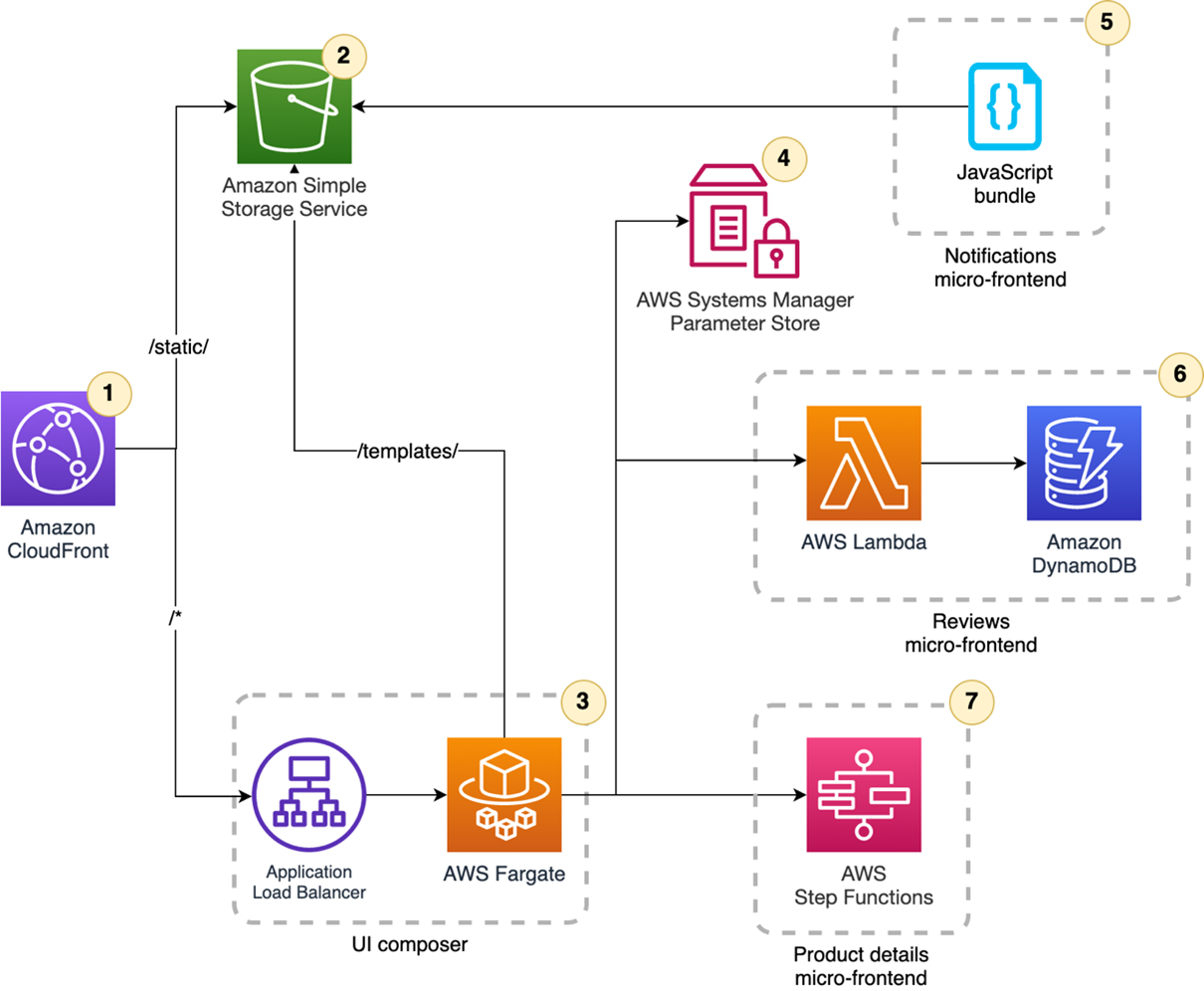
  1. The application entry point is a content delivery network (CDN) that is used for caching, performance, and security reasons.
  2. The server-side rendering approach requires a place to store all the static files to hydrate the JavaScript code in the browser and for styling components.
  3. Pages requests require a UI composer that retrieves the micro-frontends and stitches them together to provide the page consumed by a browser. It streams the final HTML page to the browser to enhance the largest contentful paint (LCP) metric from the core web vitals.
  4. Decouple micro-frontends from the UI composer relies on two mechanisms: A micro-frontends discovery that acts like a service discovery in a microservice architecture, and an HTML template per page that describes where to inject the micro-frontends inside a page. The templates can live in the same repository where the other static files are present.
  5. The notification micro-frontend reacts to user interactions, providing a notification when a user adds a product in the cart.
  6. The product details micro-frontend has highly cacheable data that doesn’t require many changes over time.
  7. The reviews micro-frontend must retrieve user reviews of a specific product.

The key element for avoiding design-time coupling in this architecture is the micro-frontends discovery. The main advantages of this approach are to provide discoverability to simplify multi-environments strategies, and also to reduce the blast radius thanks to using blue/green deployments or canary releases. This topic will be covered in depth in an upcoming post.

From high-level design into implementation

The framework-agnostic approach helps to enable control over system evolution. It achieves this by using HTML-over-the-wire, where every micro-frontend renders an HTML fragment and returns it to the UI composer.

When the UI composer gathers the HTML fragments, it composes the final page to render using transclusion. Every page is represented by a specific template hosted in static files. The UI composer retrieves the template and then retrieves placeholder references in the template that can be replaced with the micro-frontend fragments.

This is the architecture used:

Architecture diagram

  1. Amazon CloudFront provides a unique entry point to the application. The distribution has two origins: the first for static files and the second for the UI composer.
  2. Static files are hosted in an Amazon S3 bucket. They are consumed by the browser and the UI composer for HTML templates.
  3. The UI composer runs on a containers cluster in AWS Fargate. Using a containerized solution allows you to use streaming capabilities and multithreading rendering if needed.
  4. AWS Systems Manager Parameter Store is used as a basic micro-frontends discovery system. This service is a key-value store used by the UI composer for retrieving the micro-frontends endpoints to consume.
  5. The notifications micro-frontend stores the optimized JavaScript bundle in the S3 bucket. This renders on the client since it must react to user interactions.
  6. The reviews micro-frontend is composed by an AWS Lambda function with the user reviews stored in Amazon DynamoDB. It’s rendered fully server-side and it outputs an HTML fragment.
  7. The product details micro-frontend is a low-code micro-frontend using AWS Step Functions. The Express Workflow can be invoked synchronously and contains the logic for rendering the HTML fragment and a caching layer. This increases performance due to the native integration with over 200 AWS services.

Using this approach, every team developing a micro-frontend is independent to build and evolve their business domain. The main touchpoints with other teams are related to the initial integrations and the communication mechanism between micro-frontends present in the same page. When these points are achieved, every team reduces external dependencies and can embrace the evolutionary nature of micro-frontends.

Conclusion

This first post starts the journey into micro-frontends, a distributed architecture for frontend applications. The next post will explore the UI composer and micro-frontends discovery implementations.

If you are interested in learning more about micro-frontends, see the micro-frontends decisions framework, a mental model created for the initial complexity of approaching micro-frontends design. When used as a north star, the decisions framework simplifies the development of micro-frontends applications.

In the AWS reference architectures section, you can find a complete diagram similar to the application described in this blog series with additional details.

For more serverless learning resources, visit Serverless Land.

California State University Chancellor’s Office reduces cost and improves efficiency using Amazon QuickSight for streamlined HR reporting in higher education

Post Syndicated from Madi Hsieh original https://aws.amazon.com/blogs/big-data/california-state-university-chancellors-office-reduces-cost-and-improves-efficiency-using-amazon-quicksight-for-streamlined-hr-reporting-in-higher-education/

The California State University Chancellor’s Office (CSUCO) sits at the center of America’s most significant and diverse 4-year universities. The California State University (CSU) serves approximately 477,000 students and employs more than 55,000 staff and faculty members across 23 universities and 7 off-campus centers. The CSU provides students with opportunities to develop intellectually and personally, and to contribute back to the communities throughout California. For this large organization, managing a wide system of campuses while maintaining the decentralized autonomy of each is crucial. In 2019, they needed a highly secure tool to streamline the process of pulling HR data. The CSU had been using a legacy central data warehouse based on data from their financial system, but it lacked the robustness to keep up with modern technology. This wasn’t going to work for their HR reporting needs.

Looking for a tool to match the cloud-based infrastructure of their other operations, the Business Intelligence and Data Operations (BI/DO) team within the Chancellor’s Office chose Amazon QuickSight, a fast, easy-to-use, cloud-powered business analytics service that makes it easy for all employees within an organization to build visualizations, perform ad hoc analysis, and quickly get business insights from their data, any time, on any device. The team uses QuickSight to organize HR information across the CSU, implementing a centralized security system.

“It’s easy to use, very straightforward, and relatively intuitive. When you couple the experience of using QuickSight, with a huge cost difference to [the BI platform we had been using], to me, it’s a simple choice,”

– Andy Sydnor, Director Business Intelligence and Data Operations at the CSUCO.

With QuickSight, the team has the capability to harness security measures and deliver data insights efficiently across their campuses.

In this post, we share how the CSUCO uses QuickSight to reduce cost and improve efficiency in their HR reporting.

Delivering BI insights across the CSU’s 23 universities

The CSUCO serves the university system’s faculty, students, and staff by overseeing operations in several areas, including finance, HR, student information, and space and facilities. Since migrating to QuickSight in 2019, the team has built dashboards to support these operations. Dashboards include COVID-related leaves of absence, historical financial reports, and employee training data, along with a large selection of dashboards to track employee data at an individual campus level or from a system-wide perspective.

The team created a process for reading security roles from the ERP system and then translating them using QuickSight groups for internal HR reporting. QuickSight allowed them to match security measures with the benefits of low maintenance and familiarity to their end-users.

With QuickSight, the CSUCO is able to run a decentralized security process where campus security teams can provision access directly and users can get to their data faster. Before transitioning to QuickSight, the BI/DO team spent hours trying to get to specific individual-level data, but with QuickSight, the retrieval time was shortened to just minutes. For the first time, Sydnor and his team were able to pinpoint a specific employee’s work history without having to take additional actions to find the exact data they needed.

Cost savings compared to other BI tools

Sydnor shares that, for a public organization, one of the most attractive qualities of QuickSight is the immense cost savings. The BI/DO team at the Chancellor’s Office estimates that they’re saving roughly 40% on costs since switching from their previous BI platform, which is a huge benefit for a public organization of this scale. Their previous BI tool was costing them extensive amounts of money on licensing for features they didn’t require; the CSUCO felt they weren’t getting the best use of their investment.

The functionality of QuickSight to meet their reporting needs at an affordable price point is what makes QuickSight the CSUCO’s preferred BI reporting tool. Sydnor likes that with QuickSight, “we don’t have to go out and buy a subscription or a license for somebody, we can just provision access. It’s much easier to distribute the product.” QuickSight allows the CSUCO to focus their budget in other areas rather than having to pay for charges by infrequent users.

Simple and intuitive interface

Getting started in QuickSight was a no-brainer for Sydnor and his team. As a public organization, the procurement process can be cumbersome, thereby slowing down valuable time for putting their data to action. As an existing AWS customer, the CSUCO could seamlessly integrate QuickSight into their package of AWS services. An issue they were running into with other BI tools was encountering roadblocks to setting up the system, which wasn’t an issue with QuickSight, because it’s a fully managed service that doesn’t require deploying any servers.

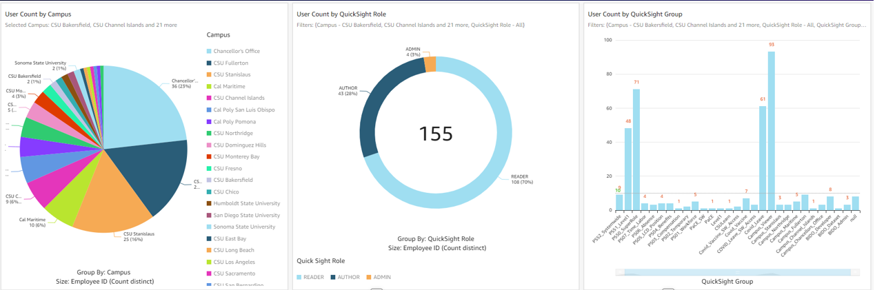
The following screenshot shows an example of the CSUCO security audit dashboard.

example of the CSUCO security audit dashboard.

Sydnor tells us, “Our previous BI tool had a huge library of visualization, but we don’t need 95% of those. Our presentations look great with the breadth of visuals QuickSight provides. Most people just want the data and ultimately, need a robust vehicle to get data out of a database and onto a table or visualization.”

Converting from their original BI tool to QuickSight was painless for his team. Sydnor tells us that he has “yet to see something we can’t do with QuickSight.” One of Sydnor’s employees who was a user of the previous tool learned QuickSight in just 30 minutes. Now, they conduct QuickSight demos all the time.

Looking to the future: Expanding BI integration and adopting Amazon QuickSight Q

With QuickSight, the Chancellor’s Office aims to roll out more HR dashboards across its campuses and extend the tool for faculty use in the classroom. In the upcoming year, two campuses are joining CSUCO in building their own HR reporting dashboards through QuickSight. The organization is also making plans to use QuickSight to report on student data and implement external-facing dashboards. Some of the data points they’re excited to explore are insights into at-risk students and classroom scheduling on campus.

Thinking ahead, CSUCO is considering Amazon QuickSight Q, a machine learning-powered natural language capability that gives anyone in an organization the ability to ask business questions in natural language and receive accurate answers with relevant visualizations. Sydnor says, “How cool would that be if professors could go in and ask simple, straightforward questions like, ‘How many of my department’s students are taking full course loads this semester?’ It has a lot of potential.”

Summary

The CSUCO is excited to be a champion of QuickSight in the CSU, and are looking for ways to increase its implementation across their organization in the future.

To learn more, visit the website for the California State University Chancellor’s Office. For more on QuickSight, visit the Amazon QuickSight product page, or browse other Big Data Blog posts featuring QuickSight.


About the authors

Madi Hsieh, AWS 2022 Summer Intern, UCLA.

Tina Kelleher, Program Manager at AWS.

Build the next generation, cross-account, event-driven data pipeline orchestration product

Post Syndicated from Maria Guerra original https://aws.amazon.com/blogs/big-data/build-the-next-generation-cross-account-event-driven-data-pipeline-orchestration-product/

This is a guest post by Mehdi Bendriss, Mohamad Shaker, and Arvid Reiche from Scout24.

At Scout24 SE, we love data pipelines, with over 700 pipelines running daily in production, spread across over 100 AWS accounts. As we democratize data and our data platform tooling, each team can create, maintain, and run their own data pipelines in their own AWS account. This freedom and flexibility is required to build scalable organizations. However, it’s full of pitfalls. With no rules in place, chaos is inevitable.

We took a long road to get here. We’ve been developing our own custom data platform since 2015, developing most tools ourselves. Since 2016, we have our self-developed legacy data pipeline orchestration tool.

The motivation to invest a year of work into a new solution was driven by two factors:

  • Lack of transparency on data lineage, especially dependency and availability of data
  • Little room to implement governance

As a technical platform, our target user base for our tooling includes data engineers, data analysts, data scientists, and software engineers. We share the vision that anyone with relevant business context and minimal technical skills can create, deploy, and maintain a data pipeline.

In this context, in 2015 we created the predecessor of our new tool, which allows users to describe their pipeline in a YAML file as a list of steps. It worked well for a while, but we faced many problems along the way, notably:

  • Our product didn’t support pipelines to be triggered by the status of other pipelines, but based on the presence of _SUCCESS files in Amazon Simple Storage Service (Amazon S3). Here we relied on periodic pulls. In complex organizations, data jobs often have strong dependencies to other work streams.
  • Given the previous point, most pipelines could only be scheduled based on a rough estimate of when their parent pipelines might finish. This led to cascaded failures when the parents failed or didn’t finish on time.
  • When a pipeline fails and gets fixed, then manually redeployed, all its dependent pipelines must be rerun manually. This means that the data producer bears the responsibility of notifying every single team downstream.

Having data and tooling democratized without the ability to provide insights into which jobs, data, and dependencies exist diminishes synergies within the company, leading to silos and problems in resource allocation. It became clear that we needed a successor for this product that would give more flexibility to the end-user, less computing costs, and no infrastructure management overhead.

In this post, we describe, through a hypothetical case study, the constraints under which the new solution should perform, the end-user experience, and the detailed architecture of the solution.

Case study

Our case study looks at the following teams:

  • The core-data-availability team has a data pipeline named listings that runs every day at 3:00 AM on the AWS account Account A, and produces on Amazon S3 an aggregate of the listings events published on the platform on the previous day.
  • The search team has a data pipeline named searches that runs every day at 5:00 AM on the AWS account Account B, and exports to Amazon S3 the list of search events that happened on the previous day.
  • The rent-journey team wants to measure a metric referred to as X; they create a pipeline named pipeline-X that runs daily on the AWS account Account C, and relies on the data of both previous pipelines. pipeline-X should only run daily, and only after both the listings and searches pipelines succeed.

User experience

We provide users with a CLI tool that we call DataMario (relating to its predecessor DataWario), and which allows users to do the following:

  • Set up their AWS account with the necessary infrastructure needed to run our solution
  • Bootstrap and manage their data pipeline projects (creating, deploying, deleting, and so on)

When creating a new project with the CLI, we generate (and require) every project to have a pipeline.yaml file. This file describes the pipeline steps and the way they should be triggered, alerting, type of instances and clusters in which the pipeline will be running, and more.

In addition to the pipeline.yaml file, we allow advanced users with very niche and custom needs to create their pipeline definition entirely using a TypeScript API we provide them, which allows them to use the whole collection of constructs in the AWS Cloud Development Kit (AWS CDK) library.

For the sake of simplicity, we focus on the triggering of pipelines and the alerting in this post, along with the definition of pipelines through pipeline.yaml.

The listings and searches pipelines are triggered as per a scheduling rule, which the team defines in the pipeline.yaml file as follows:

trigger: 
    schedule: 
        hour: 3

pipeline-x is triggered depending on the success of both the listings and searches pipelines. The team defines this dependency relationship in the project’s pipeline.yaml file as follows:

trigger: 
    executions: 
        allOf: 
            - name: listings 
              account: Account_A_ID 
              status: 
                  - SUCCESS 
            - name: searches 
              account: Account_B_ID 
              status: 
                  - SUCCESS

The executions block can define a complex set of relationships by combining the allOf and anyOf blocks, along with a logical operator operator: OR / AND, which allows mixing the allOf and anyOf blocks. We focus on the most basic use case in this post.

Accounts setup

To support alerting, logging, and dependencies management, our solution has components that must be pre-deployed in two types of accounts:

  • A central AWS account – This is managed by the Data Platform team and contains the following:
    • A central data pipeline Amazon EventBridge bus receiving all the run status changes of AWS Step Functions workflows running in user accounts
    • An AWS Lambda function logging the Step Functions workflow run changes in an Amazon DynamoDB table to verify if any downstream pipelines should be triggered based on the current event and previous run status changes log
    • A Slack alerting service to send alerts to the Slack channels specified by users
    • A trigger management service that broadcasts triggering events to the downstream buses in the user accounts
  • All AWS user accounts using the service – These accounts contain the following:
    • A data pipeline EventBridge bus that receives Step Functions workflow run status changes forwarded from the central EventBridge bus
    • An S3 bucket to store data pipelines artifacts, along their logs
    • Resources needed to run Amazon EMR clusters, like security groups, AWS Identity and Access Management (IAM) roles, and more

With the provided CLI, users can set up their account by running the following code:

$ dpc setup-user-account

Solution overview

The following diagram illustrates the architecture of the cross-account, event-driven pipeline orchestration product.

In this post, we refer to the different colored and numbered squares to reference a component in the architecture diagram. For example, the green square with label 3 refers to the EventBridge bus default component.

Deployment flow

This section is illustrated with the orange squares in the architecture diagram.

A user can create a project consisting of a data pipeline or more using our CLI tool as follows:

$ dpc create-project -n 'project-name'

The created project contains several components that allow the user to create and deploy data pipelines, which are defined in .yaml files (as explained earlier in the User experience section).

The workflow of deploying a data pipeline such as listings in Account A is as follows:

  • Deploy listings by running the command dpc deploy in the root folder of the project. An AWS CDK stack with all required resources is automatically generated.
  • The previous stack is deployed as an AWS CloudFormation template.
  • The stack uses custom resources to perform some actions, such as storing information needed for alerting and pipeline dependency management.
  • Two Lambda functions are triggered, one to store the mapping pipeline-X/slack-channels used for alerting in a DynamoDB table, and another one to store the mapping between the deployed pipeline and its triggers (other pipelines that should result in triggering the current one).
  • To decouple alerting and dependency management services from the other components of the solution, we use Amazon API Gateway for two components:
    • The Slack API.
    • The dependency management API.
  • All calls for both APIs are traced in Amazon CloudWatch log groups and two Lambda functions:
    • The Slack channel publisher Lambda function, used to store the mapping pipeline_name/slack_channels in a DynamoDB table.
    • The dependencies publisher Lambda function, used to store the pipelines dependencies (the mapping pipeline_name/parents) in a DynamoDB table.

Pipeline trigger flow

This is an event-driven mechanism that ensures that data pipelines are triggered as requested by the user, either following a schedule or a list of fulfilled upstream conditions, such as a group of pipelines succeeding or failing.

This flow relies heavily on EventBridge buses and rules, specifically two types of rules:

  • Scheduling rules.
  • Step Functions event-based rules, with a payload matching the set of statuses of all the parents of a given pipeline. The rules indicate for which set of statuses all the parents of pipeline-X should be triggered.

Scheduling

This section is illustrated with the black squares in the architecture diagram.

The listings pipeline running on Account A is set to run every day at 3:00 AM. The deployment of this pipeline creates an EventBridge rule and a Step Functions workflow for running the pipeline:

  • The EventBridge rule is of type schedule and is created on the default bus (this is the EventBridge bus responsible for listening to native AWS events—this distinction is important to avoid confusion when introducing the other buses). This rule has two main components:
    • A cron-like notation to describe the frequency at which it runs: 0 3 * * ? *.
    • The target, which is the Step Functions workflow describing the workflow of the listings pipeline.
  • The listings Step Function workflow describes and runs immediately when the rule gets triggered. (The same happens to the searches pipeline.)

Each user account has a default EventBridge bus, which listens to the default AWS events (such as the run of any Lambda function) and scheduled rules.

Dependency management

This section is illustrated with the green squares in the architecture diagram. The current flow starts after the Step Functions workflow (black square 2) starts, as explained in the previous section.

As a reminder, pipeline-X is triggered when both the listings and searches pipelines are successful. We focus on the listings pipeline for this post, but the same applies to the searches pipeline.

The overall idea is to notify all downstream pipelines that depend on it, in every AWS account, passing by and going through the central orchestration account, of the change of status of the listings pipeline.

It’s then logical that the following flow gets triggered multiple times per pipeline (Step Functions workflow) run as its status changes from RUNNING to either SUCCEEDED, FAILED, TIMED_OUT, or ABORTED. The reason being that there could be pipelines downstream potentially listening on any of those status change events. The steps are as follows:

  • The event of the Step Functions workflow starting is listened to by the default bus of Account A.
  • The rule export-events-to-central-bus, which specifically listens to the Step Function workflow run status change events, is then triggered.
  • The rule forwards the event to the central bus on the central account.
  • The event is then caught by the rule trigger-events-manager.
  • This rule triggers a Lambda function.
  • The function gets the list of all children pipelines that depend on the current run status of listings.
  • The current run is inserted in the run log Amazon Relational Database Service (Amazon RDS) table, following the schema sfn-listings, time (timestamp), status (SUCCEEDED, FAILED, and so on). You can query the run log RDS table to evaluate the running preconditions of all children pipelines and get all those that qualify for triggering.
  • A triggering event is broadcast in the central bus for each of those eligible children.
  • Those events get broadcast to all accounts through the export rules—including Account C, which is of interest in our case.
  • The default EventBridge bus on Account C receives the broadcasted event.
  • The EventBridge rule gets triggered if the event content matches the expected payload of the rule (notably that both pipelines have a SUCCEEDED status).
  • If the payload is valid, the rule triggers the Step Functions workflow pipeline-X and triggers the workflow to provision resources (which we discuss later in this post).

Alerting

This section is illustrated with the gray squares in the architecture diagram.

Many teams handle alerting differently across the organization, such as Slack alerting messages, email alerts, and OpsGenie alerts.

We decided to allow users to choose their preferred methods of alerting, giving them the flexibility to choose what kind of alerts to receive:

  • At the step level – Tracking the entire run of the pipeline
  • At the pipeline level – When it fails, or when it finishes with a SUCCESS or FAILED status

During the deployment of the pipeline, a new Amazon Simple Notification Service (Amazon SNS) topic gets created with the subscriptions matching the targets specified by the user (URL for OpsGenie, Lambda for Slack or email).

The following code is an example of what it looks like in the user’s pipeline.yaml:

notifications:
    type: FULL_EXECUTION
    targets:
        - channel: SLACK
          addresses:
               - data-pipeline-alerts
        - channel: EMAIL
          addresses:
               - [email protected]

The alerting flow includes the following steps:

  1. As the pipeline (Step Functions workflow) starts (black square 2 in the diagram), the run gets logged into CloudWatch Logs in a log group corresponding to the name of the pipeline (for example, listings).
  2. Depending on the user preference, all the run steps or events may get logged or not thanks to a subscription filter whose target is the execution-tracker-lambda Lambda function. The function gets called anytime a new event gets published in CloudWatch.
  3. This Lambda function parses and formats the message, then publishes it to the SNS topic.
  4. For the email and OpsGenie flows, the flow stops here. For posting the alert message on Slack, the Slack API caller Lambda function gets called with the formatted event payload.
  5. The function then publishes the message to the /messages endpoint of the Slack API Gateway.
  6. The Lambda function behind this endpoint runs, and posts the message in the corresponding Slack channel and under the right Slack thread (if applicable).
  7. The function retrieves the secret Slack REST API key from AWS Secrets Manager.
  8. It retrieves the Slack channels in which the alert should be posted.
  9. It retrieves the root message of the run, if any, so that subsequent messages get posted under the current run thread on Slack.
  10. It posts the message on Slack.
  11. If this is the first message for this run, it stores the mapping with the DB schema execution/slack_message_id to initiate a thread for future messages related to the same run.

Resource provisioning

This section is illustrated with the light blue squares in the architecture diagram.

To run a data pipeline, we need to provision an EMR cluster, which in turn requires some information like Hive metastore credentials, as shown in the workflow. The workflow steps are as follows:

  • Trigger the Step Functions workflow listings on schedule.
  • Run the listings workflow.
  • Provision an EMR cluster.
  • Use a custom resource to decrypt the Hive metastore password to be used in Spark jobs relying on central Hive tables or views.

End-user experience

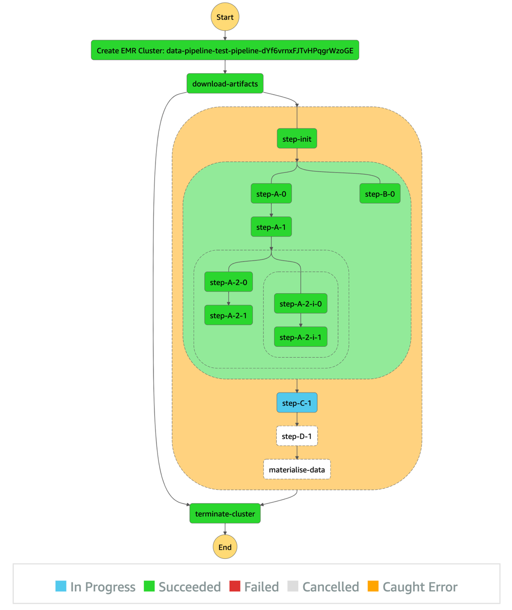
After all preconditions are fulfilled (both the listings and searches pipelines succeeded), the pipeline-X workflow runs as shown in the following diagram.

As shown in the diagram, the pipeline description (as a sequence of steps) defined by the user in the pipeline.yaml is represented by the orange block.

The steps before and after this orange section are automatically generated by our product, so users don’t have to take care of provisioning and freeing compute resources. In short, the CLI tool we provide our users synthesizes the user’s pipeline definition in the pipeline.yaml and generates the corresponding DAG.

Additional considerations and next steps

We tried to stay consistent and stick to one programming language for the creation of this product. We chose TypeScript, which played well with AWS CDK, the infrastructure as code (IaC) framework that we used to build the infrastructure of the product.

Similarly, we chose TypeScript for building the business logic of our Lambda functions, and of the CLI tool (using Oclif) we provide for our users.

As demonstrated in this post, EventBridge is a powerful service for event-driven architectures, and it plays a central and important role in our products. As for its limitations, we found that pairing Lambda and EventBridge could fulfill all our current needs and granted a high level of customization that allowed us to be creative in the features we wanted to serve our users.

Needless to say, we plan to keep developing the product, and have a multitude of ideas, notably:

  • Extend the list of core resources on which workloads run (currently only Amazon EMR) by adding other compute services, such Amazon Elastic Compute Cloud (Amazon EC2)
  • Use the Constructs Hub to allow users in the organization to develop custom steps to be used in all data pipelines (we currently only offer Spark and shell steps, which suffice in most cases)
  • Use the stored metadata regarding pipeline dependencies for data lineage, to have an overview of the overall health of the data pipelines in the organization, and more

Conclusion

This architecture and product brought many benefits. It allows us to:

  • Have a more robust and clear dependency management of data pipelines at Scout24.
  • Save on compute costs by avoiding scheduling pipelines based approximately on when its predecessors are usually triggered. By shifting to an event-driven paradigm, no pipeline gets started unless all its prerequisites are fulfilled.
  • Track our pipelines granularly and in real time on a step level.
  • Provide more flexible and alternative business logic by exposing multiple event types that downstream pipelines can listen to. For example, a fallback downstream pipeline might be run in case of a parent pipeline failure.
  • Reduce the cross-team communication overhead in case of failures or stopped runs by increasing the transparency of the whole pipelines’ dependency landscape.
  • Avoid manually restarting pipelines after an upstream pipeline is fixed.
  • Have an overview of all jobs that run.
  • Support the creation of a performance culture characterized by accountability.

We have big plans for this product. We will use DataMario to implement granular data lineage, observability, and governance. It’s a key piece of infrastructure in our strategy to scale data engineering and analytics at Scout24.

We will make DataMario open source towards the end of 2022. This is in line with our strategy to promote our approach to a solution on a self-built, scalable data platform. And with our next steps, we hope to extend this list of benefits and ease the pain in other companies solving similar challenges.

Thank you for reading.


About the authors

Mehdi Bendriss is a Senior Data / Data Platform Engineer, MSc in Computer Science and over 9 years of experience in software, ML, and data and data platform engineering, designing and building large-scale data and data platform products.

Mohamad Shaker is a Senior Data / Data Platform Engineer, with over 9 years of experience in software and data engineering, designing and building large-scale data and data platform products that enable users to access, explore, and utilize their data to build great data products.

Arvid Reiche is a Data Platform Leader, with over 9 years of experience in data, building a data platform that scales and serves the needs of the users.

Marco Salazar is a Solutions Architect working with Digital Native customers in the DACH region with over 5 years of experience building and delivering end-to-end, high-impact, cloud native solutions on AWS for Enterprise and Sports customers across EMEA. He currently focuses on enabling customers to define technology strategies on AWS for the short- and long-term that allow them achieve their desired business objectives, specializing on Data and Analytics engagements. In his free time, Marco enjoys building side-projects involving mobile/web apps, microcontrollers & IoT, and most recently wearable technologies.

Retain more for less with tiered storage for Amazon MSK

Post Syndicated from Masudur Rahaman Sayem original https://aws.amazon.com/blogs/big-data/retain-more-for-less-with-tiered-storage-for-amazon-msk/

Organizations are adopting Apache Kafka and Amazon Managed Streaming for Apache Kafka (Amazon MSK) to capture and analyze data in real-time. Amazon MSK allows you to build and run production applications on Apache Kafka without needing Kafka infrastructure management expertise or having to deal with the complex overheads associated with running Apache Kafka on your own. With increasing maturity, customers seek to build sophisticated use cases that combine aspects of real time and batch processing. For instance, you may want to train machine learning (ML) models based on historic data and then use these models to do real time inferencing. Or you may want to be able to recompute previous results when the application logic changed, e.g., when a new KPI is added to a streaming analytics application or when a bug was fixed that caused incorrect output. These use cases often require storing data for several weeks, months, or even years.

Apache Kafka is well positioned to support these kind of use cases. Data is retained in the Kafka cluster as long as required by configuring the retention policy. In this way, the most recent data can be processed in real time for low-latency use cases while historic data remains accessible in the cluster and can be processed in a batch fashion.

However, retaining data in a Kafka cluster can become expensive because storage and compute are tightly coupled in a cluster. To scale storage, you need to add more brokers. But adding more brokers with the sole purpose of increasing the storage squanders the rest of the compute resources like CPU and memory. Also, a large cluster with more nodes adds operational complexity with a longer time to recover and rebalance when a broker fails. To avoid that operational complexity and higher cost, you can move your data to Amazon Simple Storage Service (Amazon S3) for long-term access and with cost-effective storage classes in Amazon S3 you can optimize your overall storage cost. This solves cost challenges, but now you have to build and maintain that part of the architecture for data movement to a different data store. You also need to build different data processing logic using different APIs for consuming data (Kafka API for streaming, Amazon S3 API for historic reads).

Today, we’re announcing Amazon MSK tiered storage, which brings a virtually unlimited and low-cost storage tier for Amazon MSK, making it simpler and cost-effective for developers to build streaming data applications. Since the launch of Amazon MSK in 2019, we have enabled capabilities such as vertical scaling and automatic scaling of broker storage so you can operate your Kafka workloads in a cost-effective way. Earlier this year, we launched provisioned throughput which enables seamlessly scaling I/O without having to provision additional brokers. Tiered storage makes it even more cost-effective for you to run Kafka workloads. You can now store data in Apache Kafka without worrying about limits. You can effectively balance your performance and costs by using the performance-optimized primary storage for real-time data and the new low-cost tier for the historical data. With a few clicks, you can move streaming data into a lower-cost tier to store data and only pay for what you use.

Tiered storage frees you from making hard trade-offs between supporting the data retention needs of your application teams and the operational complexity that comes with it. This enables you to use the same code to process both real-time and historical data to minimize redundant workflows and simplify architectures. With Amazon MSK tiered storage, you can implement a Kappa architecture – a streaming-first software architecture deployment pattern – to use the same data processing pipeline for correctness and completeness of data over a much longer time horizon for business analysis.

How Amazon MSK tiered storage works

Let’s look at how tiered storage works for Amazon MSK. Apache Kafka stores data in files called log segments. As each segment completes, based on the segment size configured at cluster or topic level, it’s copied to the low-cost storage tier. Data is held in performance-optimized storage for a specified retention time, or up to a specified size, and then deleted. There is a separate time and size limit setting for the low-cost storage, which must be longer than the performance-optimized storage tier. If clients request data from segments stored in the low-cost tier, the broker reads the data from it and serves the data in the same way as if it were being served from the performance-optimized storage. The APIs and existing clients work with minimal changes. When your application starts reading data from the low-cost tier, you can expect an increase in read latency for the first few bytes. As you start reading the remaining data sequentially from the low-cost tier, you can expect latencies that are similar to the primary storage tier. With tiered storage, you pay for the amount of data you store and the amount of data you retrieve.

For a pricing example, let’s consider a workload where your ingestion rate is 15 MB/s, with a replication factor of 3, and you want to retain data in your Kafka cluster for 7 days. For such a workload, it requires 6x m5.large brokers, with 32.4 TB EBS storage, which costs $4,755. But if you use tiered storage for the same workload with local retention of 4 hours and overall data retention of 7 days, it requires 3x m5.large brokers, with 0.8 TB EBS storage and 9 TB of tiered storage, which costs $1,584. If you want to read all the historic data at once, it costs $13 ($0.0015 per GB retrieval cost). In this example with tiered storage, you save around 66% of your overall cost.

Get started using Amazon MSK tiered storage

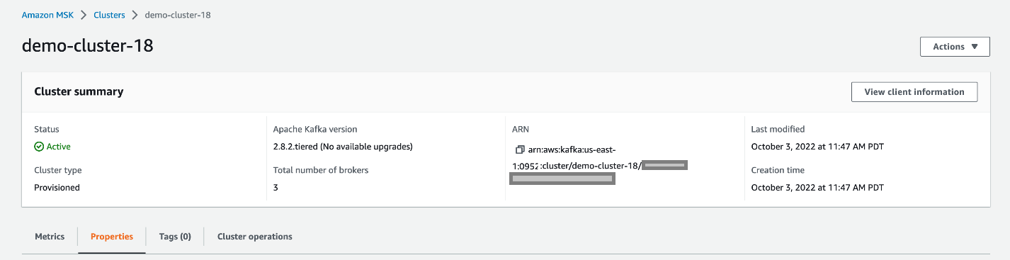
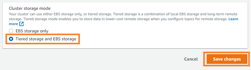
To enable tiered storage on your existing cluster, upgrade your MSK cluster to Kafka version 2.8.2.tiered and then choose Tiered storage and EBS storage as your cluster storage mode on the Amazon MSK console.

After tiered storage is enabled on the cluster level, run the following command to enable tiered storage on an existing topic. In this example, you’re enabling tiered storage on a topic called msk-ts-topic with 7 days’ retention (local.retention.ms=604800000) for a local high-performance storage tier, setting 180 days’ retention (retention.ms=15550000000) to retain the data in the low-cost storage tier, and updating the log segment size to 48 MB:

bin/kafka-configs.sh --bootstrap-server $bsrv --alter --entity-type topics --entity-name msk-ts-topic --add-config 'remote.storage.enable=true, local.retention.ms=604800000, retention.ms=15550000000, segment.bytes=50331648'

Availability and pricing

Amazon MSK tiered storage is available in all AWS regions where Amazon MSK is available excluding the AWS China, AWS GovCloud regions. This low-cost storage tier scales to virtually unlimited storage and requires no upfront provisioning. You pay only for the volume of data retained and retrieved in the low-cost tier.

For more information about this feature and its pricing, see the Amazon MSK developer guide and Amazon MSK pricing page. For finding the right sizing for your cluster, see the best practices page.

Summary

With Amazon MSK tiered storage you don’t need to provision storage for the low-cost tier or manage the infrastructure. Tiered storage enables you to scale to virtually unlimited storage. You can access data in the low-cost tier using the same clients you currently use to read data from the high-performance primary storage tier. Apache Kafka’s consumer API, streams API, and connectors consume data from both tiers without changes. You can modify the retention limits on the low-cost storage tier similarly as to how you can modify the retention limits on the high-performance storage.

Enable tiered storage on your MSK clusters today to retain data longer at a lower cost.


About the Author

Masudur Rahaman Sayem is a Streaming Architect at AWS. He works with AWS customers globally to design and build data streaming architecture to solve real-world business problems. He is passionate about distributed systems. He also likes to read, especially classic comic books.

Implementing a UML state machine using AWS Step Functions

Post Syndicated from Benjamin Smith original https://aws.amazon.com/blogs/compute/implementing-a-uml-state-machine-using-aws-step-functions/

This post is written by  Michael Havey, Senior Specialist Solutions Architect, AWS

This post shows how to model a Unified Modeling Language (UML) state machine as an AWS Step Functions workflow. A UML state machine models the behavior of an object, naming each of its possible resting states and specifying how it moves from one state to another. A Step Functions state machine implements the object behavior. This post shows how the UML diagram guides the state machine implementation and traces back to it.

State machines are often used to model real-time systems and devices. This post uses a stock order as an example. What drives a business object from one state to another is its interaction with applications through services. When the object enters a new state, it typically responds by calling the application through a service. It is typically an event arising from that application that transitions the business object to the next state. The UML model declares each state and the service interactions. Step Functions, which is designed for service orchestration, implements the behavior.

Overview

This is the approach discussed in this post:

  1. A developer implements a Step Functions state machine guided by a UML state machine designed in a third-party UML modeling tool. The implementation explicitly traces back to the UML model by logging execution of state machine activities.
  2. To invoke the target application, the Step Functions state machine invokes an AWS Lambda handler function. This invocation implements a UML state machine activity.
  3. The handler function, in turn, invokes the application. The implementation of the call is application-specific.
  4. If a callback from the application is expected, the application sends an event to a Lambda event dispatcher function. The implementation of this message exchange is application-specific.
  5. If a callback is expected, the Lambda event dispatcher function calls back the Step Functions state machine with the application event. This enables the Step Functions state machine to implement a UML state transition to the next state.

Traceability is the best way to link the Step Functions implementation to the UML model. This is because it ensures that the implementation is doing what the model intends.

An alternative is to generate Step Functions code based on the UML model using a standard XML format known as XML Metadata Interchange (XMI). A code generator tool can introspect the XMI to generate code from it. While technically feasible, UML state machines are highly expressive with many patterns and idioms. A generator often can’t produce code as lean and readable as that of a developer.

Walkthrough

This example shows a UML state machine in MagicDraw, a UML design tool. This diagram is the basis for the Step Functions implementation. This Git repository includes the XMI file for the UML diagram and the code to set up the Step Functions implementation.

The walkthrough has the following steps:

  1. Deploy Step Functions and AWS Lambda resources.
  2. Run the Step Functions state machine. Check the execution results to see how they trace back to the UML state machine.
  3. Clean up AWS resources.

Provision resources

To run this example, you need an AWS account with permission to use Step Functions and Lambda. On your machine, install the AWS Command Line Interface (CLI) and the AWS Serverless Application Model (AWS SAM) CLI.

Complete the following steps on your machine:

  1. Clone the Git repository.
  2. In a command shell, navigate to the sam folder of the clone.
  3. Run sam build to build the application.
  4. Run sam deploy –-guided to deploy the application to your AWS account.
  5. In the output, find names of Step Functions state machines and Lambda functions created.

The application creates several state machines, but in this post we consider the simplest: Test Buy Sell. The example models the behavior of a buy/sell stock order, which is based on an example from the Step Functions documentation: https://docs.aws.amazon.com/step-functions/latest/dg/sample-lambda-orchestration.html.

Explore UML model for Test BuySell

Begin with the following UML model (also available in the GitHub repository).

In the model:

  1. The black dot on the upper left is the initial state. It has an arrow (a transition) to CheckingStockPrice (a state).
  2. CheckingStockPrice has an activity, called checkStockPrice, of type do. When that state is visited, the activity is automatically run. When the activity finishes, the machine transitions automatically (a completion transition) to the next state.
  3. That state, GeneratingBuySellRecommendation, has its own do activity generateBuySellRecommendation. Completion of that activity moves to the next state.
  4. The next state is Approving, whose activity routeForApproval is of type entry. That activity is run when the state is entered. It waits for an event to move the machine forward. There are three transitions from Approving. Each has a trigger, indicating the type of event expected, called approvalComplete. Each has a guard that distinguishes the outcome of the approval.
  5. If the guard is sell, transition to the state SellingStock.
  6. If it’s buy, transition to the state BuyingStock.
  7. If it’s reject, transition to the terminate state (denoted by an X) and run a transition activity called logReject.
  8. BuyingStock and SellingStock each have a do activity – buyStock and sellStock – and transition on completion to the state ReportingResult. That state has do activity reportResult.
  9. Transition to the final state (the black dot enclosed in a circle).

Explore Step Functions implementation

Find the Step Functions implementation in the AWS Console. Under the list of State Machines, select the function with a name starting with BlogBuySell. Choose Edit to view the design of the machine. From there, open it in Workflow Studio to show the state machine workflow visualization:

The Step Function state machine implements all the activities from the UML state machine. There are Lambda tasks to implement the major state do activities: Check Stock Price, Generate Buy/Sell Recommendation, Buy Stock, Sell Stock, Report Result. There is also a Lambda function for the transition activity: Log Reject. Each Lambda function traces back to the UML state machine and uses the following format to log trace records:

{
 "sourceState": S,
 "activityType": stateEntry|stateExit|stateDo|transition,
 "activityName": N
 "trigger" T, // if transition activity
 "guard": G // if transition activity and has a guard
}

The control flow in the Step Functions state machine intuitively matches the UML state machine. The UML model has mostly completion transitions, so the Step Functions state machine largely flows from one Lambda task to another. However, I must consider the Approving state, where the machine waits for an event and then transitions in one of three directions from the choice state Buy or Sell. For this, use the Step Functions callback capability. Route For Approval is a Lambda task with the Wait For Callback option enabled. The Lambda task has three responsibilities:

  • Executes the UML state entry activity routeForApproval by calling the application.
  • Logs a tracing record that it has executed that activity.
  • Passes the task token provided by the Step Functions state machine to the application.

When the application has an approval decision, it sends an event through messaging. A separate Lambda event dispatcher function receives the message and, using the Step Functions API, calls back the Step Functions state machine with key details from the message: task token, trigger, guard.

Finally, notice the fail step after Log Reject. This implements the terminate state in the UML model.

Execute the Step Functions state machine

Execute the state machine by choosing Start Execution for the BlogBuySell state machine in the Step Functions console. Use this input:

{"appData": "Insert your JSON here"}

The console shows a graph view of the progress of the state machine. It should pause at the Route For Approval task.

Confirm traceability

Check the event view to confirm the tracing back to the UML model. The Task Scheduled event for Check Stock Price shows:

      "sourceState": "CheckingStockPrice",
      "activityType": "stateDo",
      "activityName": "checkStockPrice",

The Task Scheduled event for Generate buy/sell Recommendation shows:

      "sourceState": "GeneratingBuySellRecommendation",
      "activityType": "stateDo",
      "activityName": "generateBuySellRecommendation",

The Task Scheduled event for Route For Approval shows output resembling the following. Your taskToken will be different.

      "sourceState": "Approving",
      "activityType": "stateEntry",
      "activityName": "routeForApproval",
   "taskToken": "AAAAK . . . 99es="

Approve for buy

The state machine is waiting at Route For Approval. Simulate an application event to continue it forward. First, copy the task token value from above, excluding the quotes.

In a separate browser tab, open the Lambda console and find the function whose name contains BlogDummyUMLEventDispatcher. In the Test tab, create a new event:

{
    "taskToken": "<paste the task token here>",
    "trigger": "approvalComplete",
    "guard": "buy",
    "appData": {"x": "y"}
}
 

Choose Test to call the Lambda function with this input, which calls back the state machine.

Confirm execution of approval

In the Step Functions console, confirm that the flow is completed and taken the Buy stock path.

More examples and patterns

The AWS SAM application deploys two additional examples, which show important patterns:

  • Hierarchical or composite states.
  • Parallel or orthogonal states
  • Cancellation events
  • Internal transitions
  • Transition to history
  • Using an event loop for complex flow

You can find a discussion of these examples in the Git repo.

Comparing UML and Step Functions state machines

Step Functions transitions tasks in sequence with the ability to conditionally branch, loop, or parallelize tasks. These tasks aren’t quite the same as states in a UML model. In this approach, tasks map to UML states or transition activities.

A UML state machine spends most of its time waiting in its current state for the next event to happen. A standard workflow in Step Functions can wait too. It can run for up to one year because some activities can pause until they are called back by an external trigger. I used that capability to implement a pattern to trigger the next transition by calling back the Step Functions state machine.

Cleaning up

To avoid incurring future charges, navigate to the directory where you deployed the application and run sam delete to undeploy it.

Conclusion

This post shows code recipes for implementing UML state machines using Step Functions. If your organization already uses modeling tools, this discussion helps you understand the Step Functions implementation path. If you are a Step Functions designer, this discussion shows UML’s expressive power as the model for your implementation.

Learn more about Step Functions implementations on the Sample projects for Step Functions page.

Introducing Amazon Neptune Serverless – A Fully Managed Graph Database that Adjusts Capacity for Your Workloads

Post Syndicated from Danilo Poccia original https://aws.amazon.com/blogs/aws/introducing-amazon-neptune-serverless-a-fully-managed-graph-database-that-adjusts-capacity-for-your-workloads/

Amazon Neptune is a fully managed graph database service that makes it easy to build and run applications that work with highly connected datasets. With Neptune, you can use open and popular graph query languages to execute powerful queries that are easy to write and perform well on connected data. You can use Neptune for graph use cases such as recommendation engines, fraud detection, knowledge graphs, drug discovery, and network security.

Neptune has always been fully managed and handles time-consuming tasks such as provisioning, patching, backup, recovery, failure detection and repair. However, managing database capacity for optimal cost and performance requires you to monitor and reconfigure capacity as workload characteristics change. Also, many applications have variable or unpredictable workloads where the volume and complexity of database queries can change significantly. For example, a knowledge graph application for social media may see a sudden spike in queries due to sudden popularity.

Introducing Amazon Neptune Serverless
Today, we’re making that easier with the launch of Amazon Neptune Serverless. Neptune Serverless scales automatically as your queries and your workloads change, adjusting capacity in fine-grained increments to provide just the right amount of database resources that your application needs. In this way, you pay only for the capacity you use. You can use Neptune Serverless for development, test, and production workloads and optimize your database costs compared to provisioning for peak capacity.

With Neptune Serverless you can quickly and cost-effectively deploy graphs for your modern applications. You can start with a small graph, and as your workload grows, Neptune Serverless will automatically and seamlessly scale your graph databases to provide the performance you need. You no longer need to manage database capacity and you can now run graph applications without the risk of higher costs from over-provisioning or insufficient capacity from under-provisioning.

With Neptune Serverless, you can continue to use the same query languages (Apache TinkerPop Gremlin, openCypher, and RDF/SPARQL) and features (such as snapshots, streams, high availability, and database cloning) already available in Neptune.

Let’s see how this works in practice.

Creating an Amazon Neptune Serverless Database
In the Neptune console, I choose Databases in the navigation pane and then Create database. For Engine type, I select Serverless and enter my-database as the DB cluster identifier.

Console screenshot.

I can now configure the range of capacity, expressed in Neptune capacity units (NCUs), that Neptune Serverless can use based on my workload. I can now choose a template that will configure some of the next options for me. I choose the Production template that by default creates a read replica in a different Availability Zone. The Development and Testing template would optimize my costs by not having a read replica and giving access to DB instances that provide burstable capacity.

Console screenshot.

For Connectivity, I use my default VPC and its default security group.

Console screenshot.

Finally, I choose Create database. After a few minutes, the database is ready to use. In the list of databases, I choose the DB identifier to get the Writer and Reader endpoints that I am going to use later to access the database.

Using Amazon Neptune Serverless
There is no difference in the way you use Neptune Serverless compared to a provisioned Neptune database. I can use any of the query languages supported by Neptune. For this walkthrough, I choose to use openCypher, a declarative query language for property graphs originally developed by Neo4j that was open-sourced in 2015 and contributed to the openCypher project.

To connect to the database, I start an Amazon Linux Amazon Elastic Compute Cloud (Amazon EC2) instance in the same AWS Region and associate the default security group and a second security group that gives me SSH access.

With a property graph I can represent connected data. In this case, I want to create a simple graph that shows how some AWS services are part of a service category and implement common enterprise integration patterns.

I use curl to access the Writer openCypher HTTPS endpoint and create a few nodes that represent patterns, services, and service categories. The following commands are split into multiple lines in order to improve readability.

curl https://<my-writer-endpoint>:8182/openCypher \
-d "query=CREATE (mq:Pattern {name: 'Message Queue'}),
(pubSub:Pattern {name: 'Pub/Sub'}),
(eventBus:Pattern {name: 'Event Bus'}),
(workflow:Pattern {name: 'WorkFlow'}),
(applicationIntegration:ServiceCategory {name: 'Application Integration'}),
(sqs:Service {name: 'Amazon SQS'}), (sns:Service {name: 'Amazon SNS'}),
(eventBridge:Service {name: 'Amazon EventBridge'}), (stepFunctions:Service {name: 'AWS StepFunctions'}),
(sqs)-[:IMPLEMENT]->(mq), (sns)-[:IMPLEMENT]->(pubSub),
(eventBridge)-[:IMPLEMENT]->(eventBus),
(stepFunctions)-[:IMPLEMENT]->(workflow),
(applicationIntegration)-[:CONTAIN]->(sqs),
(applicationIntegration)-[:CONTAIN]->(sns),
(applicationIntegration)-[:CONTAIN]->(eventBridge),
(applicationIntegration)-[:CONTAIN]->(stepFunctions);"

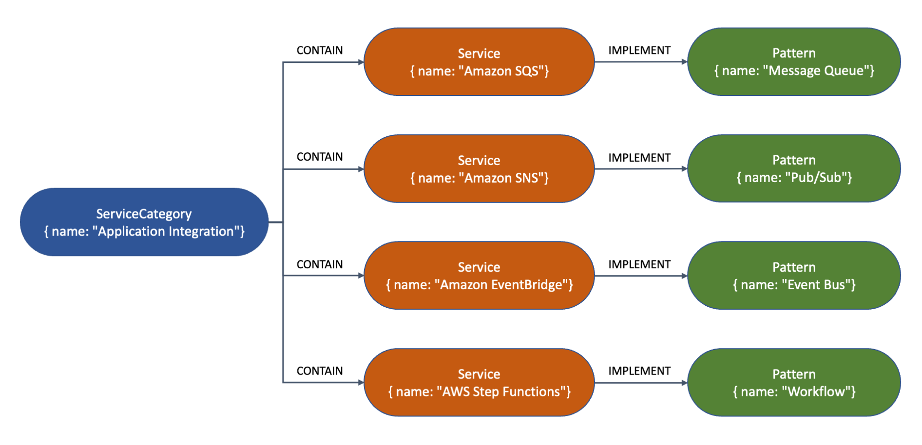
This is a visual representation of the nodes and their relationships for the graph created by the previous command. The type (such as Service or Pattern) and properties (such as name) are shown inside each node. The arrows represent the relationships (such as CONTAIN or IMPLEMENT) between the nodes.

Visualization of graph data.

Now, I query the database to get some insights. To query the database, I can use either a Writer or a Reader endpoint. First, I want to know the name of the service implementing the “Message Queue” pattern. Note how the syntax of openCypher resembles that of SQL with MATCH instead of SELECT.

curl https://<my-endpoint>:8182/openCypher \
-d "query=MATCH (s:Service)-[:IMPLEMENT]->(p:Pattern {name: 'Message Queue'}) RETURN s.name;"
{
  "results" : [ {
    "s.name" : "Amazon SQS"
  } ]
}

I use the following query to see how many services are in the “Application Integration” category. This time, I use the WHERE clause to filter results.

curl https://<my-endpoint>:8182/openCypher \
-d "query=MATCH (c:ServiceCategory)-[:CONTAIN]->(s:Service) WHERE c.name='Application Integration' RETURN count(s);"
{
  "results" : [ {
    "count(s)" : 4
  } ]
}

There are many options now that I have this graph database up and running. I can add more data (services, categories, patterns) and more relationships between the nodes. I can focus on my application and let Neptune Serverless manage capacity and infrastructure for me.

Availability and Pricing
Amazon Neptune Serverless is available today in the following AWS Regions: US East (Ohio, N. Virginia), US West (N. California, Oregon), Asia Pacific (Tokyo), and Europe (Ireland, London).

With Neptune Serverless, you only pay for what you use. The database capacity is adjusted to provide the right amount of resources you need in terms of Neptune capacity units (NCUs). Each NCU is a combination of approximately 2 gibibytes (GiB) of memory with corresponding CPU and networking. The use of NCUs is billed per second. For more information, see the Neptune pricing page.

Having a serverless graph database opens many new possibilities. To learn more, see the Neptune Serverless documentation. Let us know what you build with this new capability!

Simplify the way you work with highly connected data using Neptune Serverless.

Danilo

Serverless and Application Integration sessions at AWS re:Invent 2022

Post Syndicated from James Beswick original https://aws.amazon.com/blogs/compute/serverless-and-application-integration-sessions-at-aws-reinvent-2022/

This post is written by Josh Kahn, Tech Leader, AWS Serverless.

AWS re:Invent 2022 is only a few weeks away, featuring an exciting slate of sessions on Serverless and Application Integration. This post highlights many of the sessions we are hosting on Serverless and Application Integration. It groups sessions by theme to help you quickly find the sessions most interesting to you.

AWS re:Invent 2022

As in past years, the conference offers a variety of session formats:

  • Breakout sessions: lecture-style presentations delivered by AWS experts, builders, and customers.
  • Builder’s sessions: smaller sessions led by AWS experts during which you will build a project on your own laptop.
  • Chalk talks: interactive sessions led by experts on a variety of topics. Share your own experiences and feedback.
  • Workshops: hands-on learning sessions designed to help you learn about new technologies. Bring your own laptop.

For detailed descriptions and schedule, visit the AWS re:Invent Session Catalog. If you are attending re:Invent, we would love to connect at our AWS Village and Serverlesspresso booths in the Expo or the Modern Applications Zone at the Venetian. You can also reach out to your AWS account team.

Don’t have a ticket yet? Join us in Las Vegas from November 28-December 2, 2022 by registering for re:Invent 2022.

Leadership session (SVS210)

Join Holly Mesrobian, Vice President of Serverless Compute at AWS, to learn how serverless technology empowers organizations to go to market faster while lowering cost across a wide range of applications. Learn about the innovations happening at all layers of the stack, across both serverless functions and serverless containers. Explore newly released innovations that enable more secure, reliable, and performant applications.

Getting started

Are you new to Serverless or taking your first steps? Hear from AWS experts and customers on best practices and strategies for building serverless workloads. Get hands-on with services by building the next great “to do” app or customer experience for a theme park:

We also offer a series of Builder’s Sessions where you can build the same serverless project using three different infrastructure as code frameworks (attend one or more). These sessions are an opportunity to test drive another IaC framework or understand how your framework of choice can be used with serverless:

Event-driven architectures

Event-driven architectures (EDA) are a popular approach to building modern applications. EDA utilizes events (a change in state) to communicate between decoupled services. This architectural approach lends itself well to a wide-variety of use cases from ecommerce to order fulfillment with individual components able to scale (and fail) independently.

Whether you are getting started with EDA, want to get hands-on, or dive into complex architectures, there is a session for you:

Building serverless architectures

Explore the range of tools available to build serverless architectures and cross-cutting concerns, such as security and observability. These sessions cover the brass tacks of building with serverless, going to beyond “hello world” to help builders understand how to implement a serverless strategy:

Orchestration

AWS offers several options to orchestrate complex workflows. Whether you need to tightly control data processing workflows or user sign-ups, you can take advantage of these orchestration engines to simplify, become more agile, and modernize your workflows.

Integration patterns

Explore the variety of enterprise integration patterns available using AWS, including Amazon SNS, Amazon SQS, Amazon MQ, and more. These sessions explore the wide variety of patterns available using managed services:

Advanced topics

If you are already familiar with serverless, advanced sessions provide an opportunity to go deeper, including under the hood of the AWS Lambda service. Learn advanced design patterns, best practices, and how to build performant, reliable workloads:

Building serverless applications with Java

New this year, there are several sessions dedicating to building serverless applications with the Java runtime. These sessions dive deep on best practices for building performant Java-based applications:

Other talks

Serverless has become such a popular topic that you will also find related sessions in other tracks as well. This list is not exhaustive, but includes talks that you may want to explore:

If you are unable to join us in-person, Breakout Sessions will be available via our YouTube channel after the event. Contact your AWS Account Team is you are interested in learning more about any of these sessions or how to bring our experts to you.

We look forward to seeing you at re:Invent 2022! For more serverless learning resources, visit Serverless Land.

Propagating valid mTLS client certificate identity to downstream services using Amazon API Gateway

Post Syndicated from Eric Johnson original https://aws.amazon.com/blogs/compute/propagating-valid-mtls-client-certificate-identity-to-downstream-services-using-amazon-api-gateway/

This blog written by Omkar Deshmane, Senior SA and Anton Aleksandrov, Principal SA, Serverless.

This blog shows how to use Amazon API Gateway with a custom authorizer to process incoming requests, validate the mTLS client certificate, extract the client certificate subject, and propagate it to the downstream application in a base64 encoded HTTP header.

This pattern allows you to terminate mTLS at the edge so downstream applications do not need to perform client certificate validation. With this approach, developers can focus on application logic and offload mTLS certificate management and validation to a dedicated service, such as API Gateway.

Overview

Authentication is one of the core security aspects that you must address when building a cloud application. Successful authentication proves you are who you are claiming to be. There are various common authentication patterns, such as cookie-based authentication, token-based authentication, or the topic of this blog – a certificate-based authentication.

Transport Layer Security (TLS) certificates are at the core of a secure and safe internet. TLS certificates secure the connection between the client and server by encrypting data, ensuring private communication. When using the TLS protocol, the server must prove its identity to the client using a certificate signed by a certificate authority trusted by the client.

Mutual TLS (mTLS) introduces an additional layer of security, in which both the client and server must prove their identities to each other. Developers commonly use mTLS for application-to-application authentication — using digital certificates to represent both client and server apps is a common authentication pattern for building such workflows. We highly recommended decoupling the mTLS implementation from the application business logic so that you do not have to update the application when changing the mTLS configuration. It is a common pattern to implement the mTLS authentication and termination in a network appliance at the edge, such as Amazon API Gateway.

In this solution, we show a pattern of using API Gateway with an authorizer implemented with AWS Lambda to validate the mTLS client certificate, extract the client certificate subject, and propagate it to the downstream application in a base64 encoded HTTP header.

While this blog describes how to implement this pattern for identities extracted from the mTLS client certificates, you can generalize it and apply to propagating information obtained via any other means of authentication.

mTLS Sample Application

This blog includes a sample application implemented using the AWS Serverless Application Model (AWS SAM). It creates a demo environment containing resources like API Gateway, a Lambda authorizer, and an Amazon EC2 instance, which simulates the backend application.

The EC2 instance is used for the backend application to mimic common customer scenarios. You can use any other type of compute, such as Lambda functions or containerized applications with Amazon Elastic Container Service (Amazon ECS) or Amazon Elastic Kubernetes Service (Amazon EKS), as a backend application layer as well.

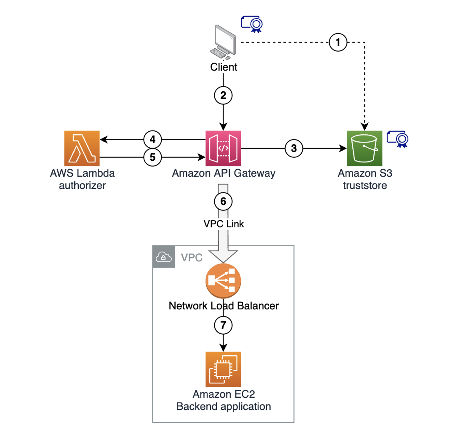
The following diagram shows the solution architecture:

Example architecture diagram

Example architecture diagram

  1. Store the client certificate in a trust store in an Amazon S3 bucket.
  2. The client makes a request to the API Gateway endpoint, supplying the client certificate to establish the mTLS session.
  3. API Gateway retrieves the trust store from the S3 bucket. It validates the client certificate, matches the trusted authorities, and terminates the mTLS connection.
  4. API Gateway invokes the Lambda authorizer, providing the request context and the client certificate information.
  5. The Lambda authorizer extracts the client certificate subject. It performs any necessary custom validation, and returns the extracted subject to API Gateway as a part of the authorization context.
  6. API Gateway injects the subject extracted in the previous step into the integration request HTTP header and sends the request to a downstream endpoint.
  7. The backend application receives the request, extracts the injected subject, and uses it with custom business logic.

Prerequisites and deployment

Some resources created as part of this sample architecture deployment have associated costs, both when running and idle. This includes resources like Amazon Virtual Private Cloud (Amazon VPC), VPC NAT Gateway, and EC2 instances. We recommend deleting the deployed stack after exploring the solution to avoid unexpected costs. See the Cleaning Up section for details.

Refer to the project code repository for instructions to deploy the solution using AWS SAM. The deployment provisions multiple resources, taking several minutes to complete.

Following the successful deployment, refer to the RestApiEndpoint variable in the Output section to locate the API Gateway endpoint. Note this value for testing later.

AWS CloudFormation output

AWS CloudFormation output

Key areas in the sample code

There are two key areas in the sample project code.

In src/authorizer/index.js, the Lambda authorizer code extracts the subject from the client certificate. It returns the value as part of the context object to API Gateway. This allows API Gateway to use this value in the subsequent integration request.

const crypto = require('crypto');

exports.handler = async (event) => {
    console.log ('> handler', JSON.stringify(event, null, 4));

    const clientCertPem = event.requestContext.identity.clientCert.clientCertPem;
    const clientCert = new crypto.X509Certificate(clientCertPem);
    const clientCertSub = clientCert.subject.replaceAll('\n', ',');

    const response = {
        principalId: clientCertSub,
        context: { clientCertSub },
        policyDocument: {
            Version: '2012-10-17',
            Statement: [{
                Action: 'execute-api:Invoke',
                Effect: 'allow',
                Resource: event.methodArn
            }]
        }
    };

    console.log('Authorizer Response', JSON.stringify(response, null, 4));
    return response;
};

In template.yaml, API Gateway injects the client certificate subject extracted by the Lambda authorizer previously into the integration request as X-Client-Cert-Sub HTTP header. X-Client-Cert-Sub is a custom header name and you can choose any other custom header name instead.

SayHelloGetMethod:
    Type: AWS::ApiGateway::Method
    Properties:
      AuthorizationType: CUSTOM
      AuthorizerId: !Ref CustomAuthorizer
      HttpMethod: GET
      ResourceId: !Ref SayHelloResource
      RestApiId: !Ref RestApi
      Integration:
        Type: HTTP_PROXY
        ConnectionType: VPC_LINK
        ConnectionId: !Ref VpcLink
        IntegrationHttpMethod: GET
        Uri: !Sub 'http://${NetworkLoadBalancer.DNSName}:3000/'
        RequestParameters:
          'integration.request.header.X-Client-Cert-Sub': 'context.authorizer.clientCertSub' 

Testing the example

You create a client key and certificate during the deployment, which are stored in the /certificates directory. Use the curl command to make a request to the REST API endpoint using these files.

curl --cert certificates/client.pem --key certificates/client.key \
<use the RestApiEndpoint found in CloudFormation output>
Example flow diagram

Example flow diagram

The client request to API Gateway uses mTLS with a client certificate supplied for mutual TLS authentication. API Gateway uses the Lambda authorizer to extract the certificate subject, and inject it into the Integration request.

The HTTP server runs on the EC2 instance, simulating the backend application. It accepts the incoming request and echoes it back, supplying request headers as part of the response body. The HTTP response received from the backend application contains a simple message and a copy of the request headers sent from API Gateway to the backend.

One header is x-client-cert-sub with the Common Name value you provided to the client certificate during creation. Verify that the value matches the Common Name that you provided when generating the client certificate.

Response example

Response example

API Gateway validated the mTLS client certificate, used the Lambda authorizer to extract the subject common name from the certificate, and forwarded it to the downstream application.

Cleaning up

Use the sam delete command in the api-gateway-certificate-propagation directory to delete the sample application infrastructure:

sam delete

You can also refer to the project code repository for the clean-up instructions.

Conclusion

This blog shows how to use the API Gateway with a Lambda authorizer for mTLS client certificate validation, custom field extraction, and downstream propagation to backend systems. This pattern allows you to terminate mTLS at the edge so that downstream applications are not responsible for client certificate validation.

For additional documentation, refer to Using API Gateway with Lambda Authorizer. Download the sample code from the project code repository. For more serverless learning resources, visit Serverless Land.

Code versioning using AWS Glue Studio and GitHub

Post Syndicated from Leonardo Gomez original https://aws.amazon.com/blogs/big-data/code-versioning-using-aws-glue-studio-and-github/

AWS Glue now offers integration with Git, an open-source version control system widely used across the developer community. Thanks to this integration, you can incorporate your existing DevOps practices on AWS Glue jobs. AWS Glue is a serverless data integration service that helps you create jobs based on Apache Spark or Python to perform extract, transform, and load (ETL) tasks on datasets of almost any size.

Git integration in AWS Glue works for all AWS Glue job types, both visual and code-based. It offers built-in integration with both GitHub and AWS CodeCommit, and makes it easier to use automation tools like Jenkins and AWS CodeDeploy to deploy AWS Glue jobs. AWS Glue Studio’s visual editor now also supports parameterizing data sources and targets for transparent deployments between environments.

Overview of solution

To demonstrate how to integrate AWS Glue Studio with a code hosting platform for version control and collaboration, we use the Toronto parking tickets dataset, specifically the data about parking tickets issued in the city of Toronto in 2019. The goal is to create a job to filter parking tickets based on a specific category and push the code to a GitHub repo for version control. After the job is uploaded on the repository, we make some changes to the code and pull the changes back to the AWS Glue job.

Prerequisites

For this walkthrough, you should have the following prerequisites:

If the AWS account you use to follow this post uses AWS Lake Formation to manage permissions on the AWS Glue Data Catalog, make sure that you log in as a user with access to create databases and tables. For more information, refer to Implicit Lake Formation permissions.

Launch your CloudFormation stack

To create your resources for this use case, complete the following steps:

  1. Launch your CloudFormation stack in us-east-1:
  2. Under Parameters, for paramBucketName, enter a name for your S3 bucket (include your account number).
  3. Select I acknowledge that AWS CloudFormation might create IAM resources with custom names.
  4. Choose Create stack.
  5. Wait until the creation of the stack is complete, as shown on the AWS CloudFormation console.

Launching this stack creates AWS resources. You need the following resources from the Outputs tab for the next steps:

  • CFNGlueRole – The IAM role to run AWS Glue jobs
  • S3Bucket – The name of the S3 bucket to store solution-related files
  • CFNDatabaseBlog – The AWS Glue database to store the table related to this post
  • CFNTableTickets – The AWS Glue table to use as part of the sample job

Configure the GitHub repository

We use GitHub as the source control system for this post. In order to use it, you need a GitHub account. After the account is created, you need to create following components:

  • GitHub repository – Create a repository and name it glue-ver-log. For instructions, refer to Create a repo.
  • Branch – Create a branch and name it develop. For instructions, refer to Managing branches.
  • Personal access token – For instructions, refer to Creating a personal access token. Make sure to keep the personal access token handy because you use it in later steps.

Create an AWS Glue Studio job

Now that the infrastructure is set up, let’s author an AWS Glue job in our account. Complete the following steps:

  1. On the AWS Glue console, choose Jobs in the navigation pane.
  2. Select Visual job with blank canvas and choose Create.
  3. Enter a name for the job using the title editor. For example, aws-glue-git-demo-job.
  4. On the Visual tab, choose Source and then choose AWS Glue Data Catalog

  5. For Database, choose torontoparking and for Table, choose tickets.
  6. Choose Transform and then Filter.
  7. Add a filter by infraction_description and set the value to PARK ON PRIVATE PROPERTY.
  8. Choose Target and then choose Amazon S3.
  9. For Format, choose Parquet.
  10. For S3 Target Location, enter s3://glue-version-blog-YOUR ACOUNT NUMBER/output/.
  11. For Data Catalog update options, select Do not update the Data Catalog.
  12. Go to the Script tab to verify that a script has been generated.
  13. Go to the Job Details tab to make sure that the role GlueBlogRole is selected and leave everything else with the default values.

    Because the catalog table names in the production and development environment may be different, AWS Glue Studio now allows you to parameterize visual jobs. To do so, perform the following steps:
  14. On the Job details tab, scroll to the Job parameters section under Advanced properties.
  15. Create the --source.database.name parameter and set the value to torontoparking.
  16. Create the --souce.table.name parameter and set the value to tickets.
  17. Go to the Visual tab and choose the AWS Glue Data Catalog node.Notice that under each of the database and table selection options is a new expandable section called Use runtime parameters.
  18. The run time parameters are auto populated with the parameters previously created. Clicking on the Apply button will apply the default values for these parameters.
  19. Go to the Script tab to review the script.AWS Glue Studio code generation automatically picks up the parameters to resolve and then makes the appropriate references in the script so that the parameters can be used.
    Now the job is ready to be pushed into the develop branch of our version control system.
  20. On the Version Control tab, for Version control system, choose Github.
  21. For Personal access token, enter your GitHub token.
  22. For Repository owner, enter the owner of your GitHub account.
  23. In the Repository configuration section, for Repository, choose glue-ver-blog.
  24. For Branch, choose develop.
  25. For Folder, leave it blank.
  26. Choose Save to save the job.

Push to the repository

Now the job can be pushed to the remote repository.

  1. On the Actions menu, choose Push to repository.
  2. Choose Confirm to confirm the operation.

    After the operation succeeds, the page reloads to reflect the latest information from the version control system. A notification shows the latest available commit and links you to the commit on GitHub.
  3. Choose the commit link to go to the repository on GitHub.

You have successfully created your first commit to GitHub from AWS Glue Studio!

Pull from the repository

Now that we have committed the AWS Glue job to GitHub, it’s time to see how we can pull changes using AWS Glue Studio. For this demo, we make a small modification in our example job using the GitHub UI and then pull the changes using AWS Glue Studio.

  1. On GitHub, choose the develop branch.
  2. Choose the aws-glue-git-demo-job folder.
  3. Choose the aws-glue-git-demo-job.json file.
  4. Choose the edit icon.
  5. Set the MaxRetries parameter to 1.
  6. Choose Commit changes.
  7. Return to the AWS Glue console and on the Actions menu, choose Pull from repository.
  8. Choose Confirm.

Notice that the commit ID has changed.

On the Job details tab, you can see that the value for Number of retries is 1.

Clean up

To avoid incurring future charges, and to clean up unused roles and policies, delete the resources you created: the datasets, CloudFormation stack, S3 bucket, AWS Glue job, AWS Glue database, and AWS Glue table.

Conclusion

This post showed how to integrate AWS Glue with GitHub, but this is only the beginning—now you can use the most popular functionalities offered by Git.

To learn more and get started using the AWS Glue Studio Git integration, refer to Configuring Git integration in AWS Glue.


About the authors

Leonardo Gómez is a Senior Analytics Specialist Solutions Architect at AWS. Based in Toronto, Canada, he has over a decade of experience in data management, helping customers around the globe address their business and technical needs.

Daiyan Alamgir is a Principal Frontend Engineer on AWS Glue based in New York. He leads the AWS Glue UI team and is focused on building interactive web-based applications for data analysts and engineers to address their data integration use cases.

Simplifying serverless permissions with AWS SAM Connectors

Post Syndicated from Eric Johnson original https://aws.amazon.com/blogs/compute/simplifying-serverless-permissions-with-aws-sam-connectors/

This post written by Kurt Tometich, Senior Solutions Architect, AWS.

Developers have been using the AWS Serverless Application Model (AWS SAM) to streamline the development of serverless applications with AWS since late 2018. Besides making it easier to create, build, test, and deploy serverless applications, AWS SAM now further simplifies permission management between serverless components with AWS SAM Connectors.

Connectors allow the builder to focus on the relationships between components without expert knowledge of AWS Identity and Access Management (IAM) or direct creation of custom policies. AWS SAM connector supports AWS Step Functions, Amazon DynamoDB, AWS Lambda, Amazon SQS, Amazon SNS, Amazon API Gateway, Amazon EventBridge and Amazon S3, with more resources planned in the future.

AWS SAM policy templates are an existing feature that helps builders deploy serverless applications with minimally scoped IAM policies. Because there are a finite number of templates, they’re a good fit when a template exists for the services you’re using. Connectors are best for those getting started and who want to focus on modeling the flow of data and events within their applications. Connectors will take the desired relationship model and create the permissions for the relationship to exist and function as intended.

In this blog post, I show you how to speed up serverless development while maintaining secure best practices using AWS SAM connector. Defining a connector in an AWS SAM template requires a source, destination, and a permission (for example, read or write). From this definition, IAM policies with minimal privileges are automatically created by the connector.

Usage

Within an AWS SAM template:

  1. Create serverless resource definitions.
  2. Define a connector.
  3. Add a source and destination ID of the resources to connect.
  4. Define the permissions (read, write) of the connection.

This example creates a Lambda function that requires write access to an Amazon DynamoDB table to keep track of orders created from a website.

AWS Lambda function needing write access to an Amazon DynamoDB table

AWS Lambda function needing write access to an Amazon DynamoDB table

The AWS SAM connector for the resources looks like the following:

LambdaDynamoDbWriteConnector:
  Type: AWS::Serverless::Connector
  Properties:
    Source:
      Id: CreateOrder
    Destination:
      Id: Orders
    Permissions:
      - Write

“LambdaDynamoDbWriteConnector” is the name of the connector, while the “Type” designates it as an AWS SAM connector. “Properties” contains the source and destination logical ID for our serverless resources found within our template. Finally, the “Permissions” property defines a read or write relationship between the components.

This basic example shows how easy it is to define permissions between components. No specific role or policy names are required, and this syntax is consistent across many other serverless components, enforcing standardization.

Example

AWS SAM connectors save you time as your applications grow and connections between serverless components become more complex. Manual creation and management of permissions become error prone and difficult at scale. To highlight the breadth of support, we’ll use an AWS Step Functions state machine to operate with several other serverless components. AWS Step Functions is a serverless orchestration workflow service that integrates natively with other AWS services.

Solution overview

Architectural overview

Architectural overview

This solution implements an image catalog moderation pipeline. Amazon Rekognition checks for inappropriate content, and detects objects and text in an image. It processes valid images and stores metadata in an Amazon DynamoDB table, otherwise emailing a notification for invalid images.

Prerequisites

  1. Git installed
  2. AWS SAM CLI version 1.58.0 or greater installed

Deploying the solution

  1. Clone the repository and navigate to the solution directory:
    git clone https://github.com/aws-samples/step-functions-workflows-collection
    cd step-functions-workflows-collection/moderated-image-catalog
  2. Open the template.yaml file located at step-functions-workflows-collection/moderated-image-catalog and replace the “ImageCatalogStateMachine:” section with the following snippet. Ensure to preserve YAML formatting.
    ImageCatalogStateMachine:
        Type: AWS::Serverless::StateMachine
        Properties:
          Name: moderated-image-catalog-workflow
          DefinitionUri: statemachine/statemachine.asl.json
          DefinitionSubstitutions:
            CatalogTable: !Ref CatalogTable
            ModeratorSNSTopic: !Ref ModeratorSNSTopic
          Policies:
            - RekognitionDetectOnlyPolicy: {}
  3. Within the same template.yaml file, add the following after the ModeratorSNSTopic section and before the Outputs section:
    # Serverless connector permissions
    StepFunctionS3ReadConnector:
      Type: AWS::Serverless::Connector
      Properties:
        Source:
          Id: ImageCatalogStateMachine
        Destination:
          Id: IngestionBucket
        Permissions:
          - Read
    
    StepFunctionDynamoWriteConnector:
      Type: AWS::Serverless::Connector
      Properties:
        Source:
          Id: ImageCatalogStateMachine
        Destination:
          Id: CatalogTable
        Permissions:
          - Write
    
    StepFunctionSNSWriteConnector:
      Type: AWS::Serverless::Connector
      Properties:
        Source:
          Id: ImageCatalogStateMachine
        Destination:
          Id: ModeratorSNSTopic
        Permissions:
          - Write

    You have removed the existing inline policies for the state machine and replaced them with AWS SAM connector definitions, except for the Amazon Rekognition policy. At the time of publishing this blog, connectors do not support Amazon Rekognition. Take some time to review each of the connector’s syntax.

  4. Deploy the application using the following command:
    sam deploy --guided

    Provide a stack name, Region, and moderators’ email address. You can accept defaults for the remaining prompts.

Verifying permissions

Once the deployment has completed, you can verify the correct role and policies.

  1. Navigate to the Step Functions service page within the AWS Management Console and ensure you have the correct Region selected.
  2. Select State machines from the left menu and then the moderated-image-catalog-workflow state machine.
  3. Select the “IAM role ARN” link, which will take you to the IAM role and policies created.

You should see a list of policies that correspond to the AWS SAM connectors in the template.yaml file with the actions and resources.

Permissions list in console

Permissions list in console

You didn’t need to supply the specific policy actions: Use Read or Write as the permission and the service handles the rest. This results in improved readability, standardization, and productivity, while retaining security best practices.

Testing

  1. Upload a test image to the Amazon S3 bucket created during the deployment step. To find the name of the bucket, navigate to the AWS CloudFormation console. Select the CloudFormation stack via the name entered as part of “sam deploy –guided.” Select the Outputs tab and note the IngestionBucket name.
  2. After uploading the image, navigate to the AWS Step Functions console and select the “moderated-image-catalog-workflow” workflow.
  3. Select Start Execution and input an event:
    {
        "bucket": "<S3-bucket-name>",
        "key": "<image-name>.jpeg"
    }
  4. Select Start Execution and observe the execution of the workflow.
  5. Depending on the image selected, it will either add to the image catalog, or send a content moderation email to the email address provided. Find out more about content considered inappropriate by Amazon Rekognition.

Cleanup

To delete any images added to the Amazon S3 bucket, and the resources created by this template, use the following commands from the same project directory.

aws s3 rm s3://< bucket_name_here> --recursive
sam delete

Conclusion

This blog post shows how AWS SAM connectors simplify connecting serverless components. View the Developer Guide to find out more about AWS SAM connectors. For further sample serverless workflows like the one used in this blog, see Serverless Land.

Announcing server-side encryption with Amazon Simple Queue Service -managed encryption keys (SSE-SQS) by default

Post Syndicated from James Beswick original https://aws.amazon.com/blogs/compute/announcing-server-side-encryption-with-amazon-simple-queue-service-managed-encryption-keys-sse-sqs-by-default/

This post is written by Sofiya Muzychko (Sr Product Manager), Nipun Chagari (Principal Solutions Architect), and Hardik Vasa (Senior Solutions Architect).

Amazon Simple Queue Service (SQS) now provides server-side encryption (SSE) using SQS-owned encryption (SSE-SQS) by default. This feature further simplifies the security posture to encrypt the message body in SQS queues.

SQS is a fully managed message queuing service that enables you to decouple and scale microservices, distributed systems, and serverless applications. Customers are increasingly decoupling their monolithic applications to microservices and moving sensitive workloads to SQS, such as financial and healthcare applications, whose compliance regulations mandate data encryption.

SQS already supports server-side encryption with customer-provided encryption keys using the AWS Key Management Service (SSE-KMS) or using SQS-owned encryption keys (SSE-SQS). Both encryption options greatly reduce the operational burden and complexity involved in protecting data. Additionally, with the SSE-SQS encryption type, you do not need to create, manage, or pay for SQS-managed encryption keys.

Using the default encryption

With this feature, all newly created queues using HTTPS (TLS) and Signature Version 4 endpoints are encrypted using SQS-owned encryption (SSE-SQS) by default, enhancing the protection of your data against unauthorized access. Any new queue created using the non-TLS endpoint will not enable SSE-SQS encryption by default. We hence encourage you to create SQS queues using HTTPS endpoints as a security best practice.

The SSE-SQS default encryption is available for both standard and FIFO. You do not need to make any code or application changes to encrypt new queues. This does not affect existing queues. You can however change the encryption option for existing queues at any time using the SQS console, AWS Command Line Interface, or API.

Create queue

The preceding image shows the SQS queue creation console wizard with configuration options for encryption. As you can see, server-side encryption is enabled by default with encryption key type SSE-SQS option selected.

Creating a new SQS queue with SSE-SQS encryption using AWS CloudFormation

Default SSE-SQS encryption is also supported in AWS CloudFormation. To learn more, see this documentation page.

Here is the sample CloudFormation template to create an SQS standard queue with SQS owned Server Side Encryption (SSE-SQS) explicitly enabled.

AWSTemplateFormatVersion: "2010-09-09"
Description: SSE-SQS Cloudformation template
Resources:
  SQSEncryptionQueue:
    Type: AWS::SQS::Queue
    Properties: 
      MaximumMessageSize: 262144
      MessageRetentionPeriod: 86400
      QueueName: SSESQSQueue
      SqsManagedSseEnabled: true
      KmsDataKeyReusePeriodSeconds: 900
      VisibilityTimeout: 30

Note that if the SqsManagedSseEnabled: true property is not specified, SSE-SQS is enabled by default.

Configuring SSE-SQS encryption for existing queues vis AWS Management Console

To configure SSE-SQS encryption for an existing queue using the SQS console:

  1. Navigate to the SQS console at https://console.aws.amazon.com/sqs/.
  2. In the navigation pane, choose Queues.
  3. Select a queue, and then choose Edit.
  4. Under the Encryption dialog box, for Server-side encryption, choose Enabled.
  5. Select Amazon SQS key (SSE-SQS).
  6. Choose Save.

Edit standard queue

To configure SSE-SQS encryption for an existing queue using the AWS CLI

To enable SSE-SQS to an existing queue with no encryption, use the following AWS CLI command

aws sqs set-queue-attributes --queue-url <queueURL> --attributes SqsManagedSseEnabled=true

Replace <queueURL> with the URL of your SQS queue.

To disable SSE-SQS for an existing queue using the AWS CLI, run:

aws sqs set-queue-attributes --queue-url <queueURL> --attributes SqsManagedSseEnabled=false

Testing the queue with the SSE-SQS encryption enabled

To test sending message to the SQS queue with SSE-SQS enabled, run:

aws sqs send-message --queue-url <queueURL> --message-body test-message

Replace <queueURL> with the URL of your SQS queue. You see the following response, which means the message is successfully sent to the queue:

{
    "MD5OfMessageBody": "beaa0032306f083e847cbf86a09ba9b2",
    "MessageId": "6e53de76-7865-4c45-a640-f058c24a619b"
}

Default SSE-SQS encryption key rotation

You can choose how often the keys will be rotated by configuring the KmsDataKeyReusePeriodSeconds queue attribute. The value must be an integer between 60 (1 minute) and 86,400 (24 hours). The default is 300 (5 minutes).

To update the KMS data key reuse period for an existing SQS queue, run:

aws sqs set-queue-attributes --queue-url <queueURL> --attributes KmsDataKeyReusePeriodSeconds=900

This configures the queue with KMS key rotation to every 900 seconds (15 minutes).

Default SSE-SQS and encrypted messages

Encrypting a message makes its contents unavailable to unauthorized or anonymous users. Anonymous requests are requests made to a queue that is open to a public network without any authentication. Note, if you are using anonymous SendMessage and ReceiveMessage requests to the newly created queues, the requests will now be rejected with SSE-SQS enabled by default.

Making anonymous requests to SQS queues does not follow SQS security best practices. We strongly recommend updating your policy to make signed requests to SQS queues using AWS SDK or AWS CLI and to continue using SSE-SQS enabled by default.

Look at the SQS service response for anonymous messages when SSE-SQS encryption is enabled. For an existing queue, you can change the queue policy to grant all users (anonymous users) SendMessage permission for a queue named EncryptionQueue:

{
  "Version": "2012-10-17",
  "Id": "Queue1_Policy_UUID",
  "Statement": [
    {
      "Sid": "Queue1_SendMessage",
      "Effect": "Allow",
      "Principal": "*",
      "Action": "sqs:SendMessage",
      "Resource": "<queueARN>"
    }
  ]
}

You can then make an anonymous request against the queue:

curl <queueURL> -d 'Action=SendMessage&MessageBody=Hello'

You get an error message similar to the following:

<?xml version="1.0"?>
<ErrorResponse
	xmlns="http://queue.amazonaws.com/doc/2012-11-05/">
	<Error>
		<Type>Sender</Type>
		<Code>AccessDenied</Code>
		<Message>Access to the resource The specified queue does not exist or you do not have access to it. is denied.</Message>
		<Detail/>
	</Error>
	<RequestId> RequestID </RequestId>
</ErrorResponse>

However, for any reason if you want to continue using anonymous requests to the newly created queues in the future, you must create or update the queue with SSE-SQS encryption disabled.

SqsManagedSseEnabled=false

You can also disable the SSE-SQS using the Amazon SQS console.

Encrypting SQS queues with your own encryption keys

You can always change the default of SSE-SQS queues encryption and use your own keys. To encrypt SQS queues with your own encryption keys using the AWS Key Management Service (SSE-KMS), the default encryption with SSE-SQS can be overwritten to SSE-KMS during the queue creation process or afterwards.

You can update the SQS queue Server-side encryption key type using the Amazon SQS console, AWS Command Line Interface, or API.

Benefits of SQS owned encryption (SSE-SQS)

There are a number of significant benefits to encrypting your data with SQS owned encryption (SSE-SQS):

  • SSE-SQS lets you transmit data more securely and improve your security posture commonly required for compliance and regulations with no additional overhead, as you do not need to create and manage encryption keys.
  • Encryption at rest using the default SSE-SQS is provided at no additional charge.
  • The encryption and decryption of your data are handled transparently and continue to deliver the same performance you expect.
  • Data is encrypted using the 256-bit Advanced Encryption Standard (AES-256 GCM algorithm), so that only authorized roles and services can access data.

In addition, customers can enable CloudWatch Alarms to alarm on activities such as authorization failures, AWS Identity and Access Management (IAM) policy changes, or tampering with CloudTrail logs to help detect and stay on top of security incidents in the customer application (to learn more, see Amazon CloudWatch User Guide).

Conclusion

SQS now provides server-side encryption (SSE) using SQS-owned encryption (SSE-SQS) by default. This enhancement makes it easier to create SQS queues, while greatly reducing the operational burden and complexity involved in protecting data.

Encryption at rest using the default SSE-SQS is provided at no additional charge and is supported for both Standard and FIFO SQS queues using HTTPS endpoints. The default SSE-SQS encryption is available now.

To learn more about Amazon Simple Queue Service (SQS), see Getting Started with Amazon SQS and Amazon Simple Queue Service Developer Guide.

For more serverless learning resources, visit Serverless Land.

ICYMI: Serverless Q3 2022

Post Syndicated from David Boyne original https://aws.amazon.com/blogs/compute/serverless-icymi-q3-2022/

Welcome to the 19th edition of the AWS Serverless ICYMI (in case you missed it) quarterly recap. Every quarter, we share all the most recent product launches, feature enhancements, blog posts, webinars, Twitch live streams, and other interesting things that you might have missed!

In case you missed our last ICYMI, check out what happened last quarter here.

AWS Lambda

AWS has now introduced tiered pricing for Lambda. With tiered pricing, customers who run large workloads on Lambda can automatically save on their monthly costs. Tiered pricing is based on compute duration measured in GB-seconds. The tiered pricing breaks down as follows:

With tiered pricing, you can save on the compute duration portion of your monthly Lambda bills. This allows you to architect, build, and run large-scale applications on Lambda and take advantage of these tiered prices automatically. To learn more about Lambda cost optimizations, watch the new serverless office hours video.

Developers are using AWS SAM CLI to simplify serverless development making it easier to build, test, package, and deploy their serverless applications.  For JavaScript and TypeScript developers, you can now simplify your Lambda development further using esbuild in the AWS SAM CLI.

Code example of esbuild with SAM

Together with esbuild and SAM Accelerate, you can rapidly iterate on your code changes in the AWS Cloud. You can approximate the same levels of productivity as when testing locally, while testing against a realistic application environment in the cloud. esbuild helps simplify Lambda development with support for tree shaking, minification, source maps, and loaders. To learn more about this feature, read the documentation.

Lambda announced support for Attribute-Based Access Control (ABAC). ABAC is designed to simplify permission management using access permissions based on tags. These can be attached to IAM resources, such as IAM users, and roles. ABAC support for Lambda functions allows you to scale your permissions as your organization innovates. It gives granular access to developers without requiring a policy update when a user or project is added, removed, or updated. To learn more about ABAC, read about ABAC for Lambda.

AWS Lambda Powertools is an open-source library to help customers discover and incorporate serverless best practices more easily. Powertools for TypeScript is now generally available and currently focused on three observability features: distributed tracing (Tracer), structured logging (Logger), and asynchronous business and application metrics (Metrics). Powertools is helping builders around the world with more than 10M downloads it is also available in Python and Java programming languages.

To learn more:

AWS Step Functions

Amazon States Language (ASL) provides a set of functions known as intrinsics that perform basic data transformations. Customers have asked for additional intrinsics to perform more data transformation tasks, such as formatting JSON strings, creating arrays, generating UUIDs, and encoding data. Step functions have now added 14 new intrinsic functions which can be grouped into six categories:

Intrinsic functions allow you to reduce the use of other services to perform basic data manipulations in your workflow. Read the release blog for use-cases and more details.

Step Functions expanded its AWS SDK integrations with support for Amazon Pinpoint API 2.0, AWS Billing Conductor,  Amazon GameSparks, and 195 more AWS API actions. This brings the total to 223 AWS Services and 10,000+ API Actions.

Amazon EventBridge

EventBridge released support for bidirectional event integrations with Salesforce, allowing customers to consume Salesforce events directly into their AWS accounts. Customers can also utilize API Destinations to send EventBridge events back to Salesforce, completing the bidirectional event integrations between Salesforce and AWS.

EventBridge also released the ability to start receiving events from GitHub, Stripe, and Twilio using quick starts. Customers can subscribe to events from these SaaS applications and receive them directly onto their EventBridge event bus for further processing. With Quick Starts, you can use AWS CloudFormation templates to create HTTP endpoints for your event bus that are configured with security best practices.

To learn more:

Amazon DynamoDB

DynamoDB now supports bulk imports from Amazon S3 into new DynamoDB tables. You can use bulk imports to help you migrate data from other systems, load test your applications, facilitate data sharing between tables and accounts, or simplify your disaster recovery and business continuity plans. Bulk imports support CSV, DynamoDB JSON, and Amazon Ion as input formats. You can get started with DynamoDB import via API calls or the AWS Management Console. To learn more, read the documentation or follow this guide.

DynamoDB now supports up to 100 actions per transaction. With Amazon DynamoDB transactions, you can group multiple actions together and submit them as a single all-or-nothing operation. The maximum number of actions in a single transaction has now increased from 25 to 100. The previous limit of 25 actions per transaction would sometimes require writing additional code to break transactions into multiple parts. Now with 100 actions per transaction, builders will encounter this limit much less frequently. To learn more about best practices for transactions, read the documentation.

Amazon SNS

SNS has introduced the public preview of message data protection to help customers discover and protect sensitive data in motion without writing custom code. With message data protection for SNS, you can scan messages in real time for PII/PHI data and receive audit reports containing scan results. You can also prevent applications from receiving sensitive data by blocking inbound messages to an SNS topic or outbound messages to an SNS subscription. These scans include people’s names, addresses, social security numbers, credit card numbers, and prescription drug codes.

To learn more:

EDA Day – London 2022

The Serverless DA team hosted the world’s first event-driven architecture (EDA) day in London on September 1. This brought together prominent figures in the event-driven architecture community, AWS, and customer speakers, and AWS product leadership from EventBridge and Step Functions.

EDA day covered 13 sessions, 3 workshops, and a Q&A panel. The conference was keynoted by Gregor Hohpe and speakers included Sheen Brisals and Sarah Hamilton from Lego, Toli Apostolidis from Cinch, David Boyne and Marcia Villalba from Serverless DA, and the AWS product team leadership for the panel. Customers could also interact with EDA experts at the Serverlesspresso bar and the Ask the Experts whiteboard.

Gregor Hohpe talking at EDA Day London 2022

Gregor Hohpe talking at EDA Day London 2022

Picture of the crowd at EDA day 2022 in London

Serverless snippets collection added to Serverless Land

Serverless Land is a website that is maintained by the Serverless Developer Advocate team to help you build with workshops, patterns, blogs, and videos. The team has extended Serverless Land and introduced the new AWS Serverless snippets collection. Builders can use serverless snippets to find and integrate tools, code examples, and Amazon CloudWatch Logs Insights queries to help with their development workflow.

Serverless Blog Posts

July

Jul 13 – Optimizing Node.js dependencies in AWS Lambda

Jul 15 – Simplifying serverless best practices with AWS Lambda Powertools for TypeScript

Jul 15 – Creating a serverless Apache Kafka publisher using AWS Lambda 

Jul 18 – Understanding AWS Lambda scaling and throughput

Jul 19 – Introducing Amazon CodeWhisperer in the AWS Lambda console (In preview)

Jul 19 – Scaling AWS Lambda permissions with Attribute-Based Access Control (ABAC)

Jul 25 – Migrating mainframe JCL jobs to serverless using AWS Step Functions

Jul 28 – Using AWS Lambda to run external transactions on Db2 for IBM i

August

Aug 1 – Using certificate-based authentication for iOS applications with Amazon SNS

Aug 4 – Introducing tiered pricing for AWS Lambda

Aug 5 – Securely retrieving secrets with AWS Lambda

Aug 8 – Estimating cost for Amazon SQS message processing using AWS Lambda

Aug 9 – Building AWS Lambda governance and guardrails

Aug 11 – Introducing the new AWS Serverless Snippets Collection

Aug 12 – Introducing bidirectional event integrations with Salesforce and Amazon EventBridge

Aug 17 – Using custom consumer group ID support for AWS Lambda event sources for MSK and self-managed Kafka

Aug 24 – Speeding up incremental changes with AWS SAM Accelerate and nested stacks

Aug 29 – Deploying AWS Lambda functions using AWS Controllers for Kubernetes (ACK)

Aug 30 – Building cost-effective AWS Step Functions workflows

September

Sep 05 – Introducing new intrinsic functions for AWS Step Functions

Sep 08 – Introducing message data protection for Amazon SNS

Sep 14 – Lifting and shifting a web application to AWS Serverless: Part 1

Sep 14 – Lifting and shifting a web application to AWS Serverless: Part 2

Videos

Serverless Office Hours – Tues 10AM PT

Weekly live virtual office hours. In each session we talk about a specific topic or technology related to serverless and open it up to helping you with your real serverless challenges and issues. Ask us anything you want about serverless technologies and applications.

YouTube: youtube.com/serverlessland
Twitch: twitch.tv/aws

July

Jul 5 – AWS SAM Accelerate GA + more!

Jul 12 – Infrastructure as actual code

Jul 19 – The AWS Step Functions Workflows Collection

Jul 26 – AWS Lambda Attribute-Based Access Control (ABAC)

August

Aug 2 – AWS Lambda Powertools for TypeScript/Node.js

Aug 9 – AWS CloudFormation Hooks

Aug 16 – Java on Lambda best-practices

Aug 30 – Alex de Brie: DynamoDB Misconceptions

September

Sep 06 – AWS Lambda Cost Optimization

Sep 13 – Amazon EventBridge Salesforce integration

Sep 20 – .NET on AWS Lambda best practices

FooBar Serverless YouTube channel

Marcia Villalba frequently publishes new videos on her popular serverless YouTube channel. You can view all of Marcia’s videos at https://www.youtube.com/c/FooBar_codes.

July

Jul 7 – Amazon Cognito – Add authentication and authorization to your web apps

Jul 14 – Add Amazon Cognito to an existing application – NodeJS-Express and React

Jul 21 – Introduction to Amazon CloudFront – Add CDN to your applications

Jul 28 – Add Amazon S3 storage and use a CDN in an existing application

August

Aug 04 – Testing serverless application locally – Demo with Node.js, Express, and React

Aug 11 – Building Amazon CloudWatch dashboards with AWS CDK

Aug 19 – Let’s code – Lift and Shift migration to Serverless of Node.js, Express, React and Mongo app

Aug 25 – Let’s code – Lift and Shift migration to Serverless, migrating Authentication and Authorization

Aug 29 – Deploying AWS Lambda functions using AWS Controllers for Kubernetes (ACK)

September

Sep 1 – Run Artillery in a Lambda function | Load test your serverless applications

Sep 8 – Let’s code – Lift and Shift migration to Serverless, migrating Storage with Amazon S3 and CloudFront

Sep 15 – What are Event-Driven Architectures? Why we care?

Sep 22 – Queues – Point to Point Messaging – Exploring Event-Driven Patterns

Still looking for more?

The Serverless landing page has more information. The Lambda resources page contains case studies, webinars, whitepapers, customer stories, reference architectures, and even more Getting Started tutorials.

You can also follow the Serverless Developer Advocacy team on Twitter to see the latest news, follow conversations, and interact with the team.

D1: our quest to simplify databases

Post Syndicated from Nevi Shah original https://blog.cloudflare.com/whats-new-with-d1/

D1: our quest to simplify databases

D1: our quest to simplify databases

When we announced D1 in May of this year, we knew it would be the start of something new – our first SQL database with Cloudflare Workers. Prior to D1 we’ve announced storage options like KV (key-value store), Durable Objects (single location, strongly consistent data storage) and R2 (blob storage). But the question always remained “How can I store and query relational data without latency concerns and an easy API?”

The long awaited “Cloudflare Database” was the true missing piece to build your application entirely on Cloudflare’s global network, going from a blank canvas in VSCode to a full stack application in seconds. Compatible with the popular SQLite API, D1 empowers developers to build out their databases without getting bogged down by complexity and having to manage every underlying layer.

Since our launch announcement in May and private beta in June, we’ve made great strides in building out our vision of a serverless database. With D1 still in private beta but an open beta on the horizon, we’re excited to show and tell our journey of building D1 and what’s to come.

The D1 Experience

We knew from Cloudflare Workers feedback that using Wrangler as the mechanism to create and deploy applications is loved and preferred by many. That’s why when Wrangler 2.0 was announced this past May alongside D1, we took advantage of the new and improved CLI for every part of the experience from data creation to every update and iteration. Let’s take a quick look on how to get set up in a few easy steps.

Create your database

With the latest version of Wrangler installed, you can create an initialized empty database with a quick

npx wrangler d1 create my_database_name

To get your database up and running! Now it’s time to add your data.

Bootstrap it

It wouldn’t be the “Cloudflare way” if you had to sit through an agonizingly long process to get set up. So we made it easy and painless to bring your existing data from an old database and bootstrap your new D1 database.  You can run

wrangler d1 execute my_database-name --file ./filename.sql

and pass through an existing SQLite .sql file of your choice. Your database is now ready for action.

Develop & Test Locally

With all the improvements we’ve made to Wrangler since version 2 launched a few months ago, we’re pleased to report that D1 has full remote & local wrangler dev support:

D1: our quest to simplify databases

When running wrangler dev -–local -–persist, an SQLite file will be created inside .wrangler/state. You can then use a local GUI program for managing it, like SQLiteFlow (https://www.sqliteflow.com/) or Beekeeper (https://www.beekeeperstudio.io/).

Or you can simply use SQLite directly with the SQLite command line by running sqlite3 .wrangler/state/d1/DB.sqlite3:

D1: our quest to simplify databases

Automatic backups & one-click restore

No matter how much you test your changes, sometimes things don’t always go according to plan. But with Wrangler you can create a backup of your data, view your list of backups or restore your database from an existing backup. In fact, during the beta, we’re taking backups of your data every hour automatically and storing them in R2, so you will have the option to rollback if needed.

D1: our quest to simplify databases

And the best part – if you want to use a production snapshot for local development or to reproduce a bug, simply copy it into the .wrangler/state directory and wrangler dev –-local –-persist will pick it up!

Let’s download a D1 backup to our local disk. It’s SQLite compatible.

D1: our quest to simplify databases

Now let’s run our D1 worker locally, from the backup.

D1: our quest to simplify databases

Create and Manage from the dashboard

However, we realize that CLIs are not everyone’s jam. In fact, we believe databases should be accessible to every kind of developer – even those without much database experience! D1 is available right from the Cloudflare dashboard giving you near total command parity with Wrangler in just a few clicks. Bootstrapping your database, creating tables, updating your database, viewing tables and triggering backups are all accessible right at your fingertips.

D1: our quest to simplify databases

Changes made in the UI are instantly available to your Worker — no deploy required!

We’ve told you about some of the improvements we’ve landed since we first announced D1, but as always, we also wanted to give you a small taste (with some technical details) of what’s ahead. One really important functionality of a database is transactions — something D1 wouldn’t be complete without.

Sneak peek: how we’re bringing JavaScript transactions to D1

With D1, we strive to present a dramatically simplified interface to creating and querying relational data, which for the most part is a good thing. But simplification occasionally introduces drawbacks, where a use-case is no longer easily supported without introducing some new concepts. D1 transactions are one example.

Transactions are a unique challenge

You don’t need to specify where a Cloudflare Worker or a D1 database run—they simply run everywhere they need to. For Workers, that is as close as possible to the users that are hitting your site right this second. For D1 today, we don’t try to run a copy in every location worldwide, but dynamically manage the number and location of read-only replicas based on how many queries your database is getting, and from where. However, for queries that make changes to a database (which we generally call “writes” for short), they all have to travel back to the single Primary D1 instance to do their work, to ensure consistency.

But what if you need to do a series of updates at once? While you can send multiple SQL queries with .batch() (which does in fact use database transactions under the hood), it’s likely that, at some point, you’ll want to interleave database queries & JS code in a single unit of work.

This is exactly what database transactions were invented for, but if you try running BEGIN TRANSACTION in D1 you’ll get an error. Let’s talk about why that is.

Why native transactions don’t work
The problem arises from SQL statements and JavaScript code running in dramatically different places—your SQL executes inside your D1 database (primary for writes, nearest replica for reads), but your Worker is running near the user, which might be on the other side of the world. And because D1 is built on SQLite, only one write transaction can be open at once. Meaning that, if we permitted BEGIN TRANSACTION, any one Worker request, anywhere in the world, could effectively block your whole database! This is a quite dangerous thing to allow:

  • A Worker could start a transaction then crash due to a software bug, without calling ROLLBACK. The primary would be blocked, waiting for more commands from a Worker that would never come (until, probably, some timeout).
  • Even without bugs or crashes, transactions that require multiple round-trips between JavaScript and SQL could end up blocking your whole system for multiple seconds, dramatically limiting how high an application built with Workers & D1 could scale.

But allowing a developer to define transactions that mix both SQL and JavaScript makes building applications with Workers & D1 so much more flexible and powerful. We need a new solution (or, in our case, a new version of an old solution).

A way forward: stored procedures
Stored procedures are snippets of code that are uploaded to the database, to be executed directly next to the data. Which, at first blush, sounds exactly like what we want.

However, in practice, stored procedures in traditional databases are notoriously frustrating to work with, as anyone who’s developed a system making heavy use of them will tell you:

  • They’re often written in a different language to the rest of your application. They’re usually written in (a specific dialect of) SQL or an embedded language like Tcl/Perl/Python. And while it’s technically possible to write them in JavaScript (using an embedded V8 engine), they run in such a different environment to your application code it still requires significant context-switching to maintain them.
  • Having both application code and in-database code affects every part of the development lifecycle, from authoring, testing, deployment, rollbacks and debugging. But because stored procedures are usually introduced to solve a specific problem, not as a general purpose application layer, they’re often managed completely manually. You can end up with them being written once, added to the database, then never changed for fear of breaking something.

With D1, we can do better.

The point of a stored procedure was to execute directly next to the data—uploading the code and executing it inside the database was simply a means to that end. But we’re using Workers, a global JavaScript execution platform, can we use them to solve this problem?

It turns out, absolutely! But here we have a few options of exactly how to make it work, and we’re working with our private beta users to find the right API. In this section, I’d like to share with you our current leading proposal, and invite you all to give us your feedback.

When you connect a Worker project to a D1 database, you add the section like the following to your wrangler.toml:

[[ d1_databases ]]
# What binding name to use (e.g. env.DB):
binding = "DB"
# The name of the DB (used for wrangler d1 commands):
database_name = "my-d1-database"
# The D1's ID for deployment:
database_id = "48a4224e-...3b09"
# Which D1 to use for `wrangler dev`:
# (can be the same as the previous line)
preview_database_id = "48a4224e-...3b09"

# NEW: adding "procedures", pointing to a new JS file:
procedures = "./src/db/procedures.js"

That D1 Procedures file would contain the following (note the new db.transaction() API, that is only available within a file like this):

export default class Procedures {
  constructor(db, env, ctx) {
    this.db = db
  }

  // any methods you define here are available on env.DB.Procedures
  // inside your Worker
  async Checkout(cartId: number) {
    // Inside a Procedure, we have a new db.transaction() API
    const result = await this.db.transaction(async (txn) => {
      
      // Transaction has begun: we know the user can't add anything to
      // their cart while these actions are in progress.
      const [cart, user] = Helpers.loadCartAndUser(cartId)

      // We can update the DB first, knowing that if any of the later steps
      // fail, all these changes will be undone.
      await this.db
        .prepare(`UPDATE cart SET status = ?1 WHERE cart_id = ?2`)
        .bind('purchased', cartId)
        .run()
      const newBalance = user.balance - cart.total_cost
      await this.db
        .prepare(`UPDATE user SET balance = ?1 WHERE user_id = ?2`)
        // Note: the DB may have a CHECK to guarantee 'user.balance' can not
        // be negative. In that case, this statement may fail, an exception
        // will be thrown, and the transaction will be rolled back.
        .bind(newBalance, cart.user_id)
        .run()

      // Once all the DB changes have been applied, attempt the payment:
      const { ok, details } = await PaymentAPI.processPayment(
        user.payment_method_id,
        cart.total_cost
      )
      if (!ok) {
        // If we throw an Exception, the transaction will be rolled back
        // and result.error will be populated:
        // throw new PaymentFailedError(details)
        
        // Alternatively, we can do both of those steps explicitly
        await txn.rollback()
        // The transaction is rolled back, our DB is now as it was when we
        // started. We can either move on and try something new, or just exit.
        return { error: new PaymentFailedError(details) }
      }

      // This is implicitly called when the .transaction() block finishes,
      // but you can explicitly call it too (potentially committing multiple
      // times in a single db.transaction() block).
      await txn.commit()

      // Anything we return here will be returned by the 
      // db.transaction() block
      return {
        amount_charged: cart.total_cost,
        remaining_balance: newBalance,
      }
    })

    if (result.error) {
      // Our db.transaction block returned an error or threw an exception.
    }

    // We're still in the Procedure, but the Transaction is complete and
    // the DB is available for other writes. We can either do more work
    // here (start another transaction?) or return a response to our Worker.
    return result
  }
}

And in your Worker, your DB binding now has a “Procedures” property with your function names available:

const { error, amount_charged, remaining_balance } =
  await env.DB.Procedures.Checkout(params.cartId)

if (error) {
  // Something went wrong, `error` has details
} else {
  // Display `amount_charged` and `remaining_balance` to the user.
}

Multiple Procedures can be triggered at one time, but only one db.transaction() function can be active at once: any other write queries or other transaction blocks will be queued, but all read queries will continue to hit local replicas and run as normal. This API gives you the ability to ensure consistency when it’s essential but with the minimal impact on total overall performance worldwide.

Request for feedback

As with all our products, feedback from our users drives the roadmap and development. While the D1 API is in beta testing today, we’re still seeking feedback on the specifics. However, we’re pleased that it solves both the problems with transactions that are specific to D1 and the problems with stored procedures described earlier:

  • Code is executing as close as possible to the database, removing network latency while a transaction is open.
  • Any exceptions or cancellations of a transaction cause an instant rollback—there is no way to accidentally leave one open and block the whole D1 instance.
  • The code is in the same language as the rest of your Worker code, in the exact same dialect (e.g. same TypeScript config as it’s part of the same build).
  • It’s deployed seamlessly as part of your Worker. If two Workers bind to the same D1 instance but define different procedures, they’ll only see their own code. If you want to share code between projects or databases, extract a library as you would with any other shared code.
  • In local development and test, the procedure works just like it does in production, but without the network call, allowing seamless testing and debugging as if it was a local function.
  • Because procedures and the Worker that define them are treated as a single unit, rolling back to an earlier version never causes a skew between the code in the database and the code in the Worker.

The D1 ecosystem: contributions from the community

We’ve told you about what we’ve been up to and what’s ahead, but one of the unique things about this project is all the contributions from our users. One of our favorite parts of private betas is not only getting feedback and feature requests, but also seeing what ideas and projects come to fruition. While sometimes this means personal projects, with D1, we’re seeing some incredible contributions to the D1 ecosystem. Needless to say, the work on D1 hasn’t just been coming from within the D1 team, but also from the wider community and other developers at Cloudflare. Users have been showing off their D1 additions within our Discord private beta channel and giving others the opportunity to use them as well. We wanted to take a moment to highlight them.

workers-qb

Dealing with raw SQL syntax is powerful (and using the D1 .bind() API, safe against SQL injections) but it can be a little clumsy. On the other hand, most existing query builders assume direct access to the underlying DB, and so aren’t suitable to use with D1. So Cloudflare developer Gabriel Massadas designed a small, zero-dependency query builder called workers-qb:

import { D1QB } from 'workers-qb'
const qb = new D1QB(env.DB)

const fetched = await qb.fetchOne({
    tableName: "employees",
    fields: "count(*) as count",
    where: {
      conditions: "active = ?1",
      params: [true]
    },
})

Check out the project homepage for more information: https://workers-qb.massadas.com/.

D1 console

While you can interact with D1 through both Wrangler and the dashboard, Cloudflare Community champion, Isaac McFadyen created the very first D1 console where you can quickly execute a series of queries right through your terminal. With the D1 console, you don’t need to spend time writing the various Wrangler commands we’ve created – just execute your queries.

This includes all bells and whistles you would expect from a modern database console including multiline input, command history, validation for things D1 may not yet support, and ability to save your Cloudflare credentials for later use.

Check out the full project on GitHub or NPM for more information.

Miniflare test Integration

The Miniflare project, which powers Wrangler’s local development experience, also provides fully-fledged test environments for popular JavaScript test runners, Jest and Vitest. With this comes the concept of Isolated Storage, allowing each test to run independently, so that changes made in one don’t affect the others. Brendan Coll, creator of Miniflare, guided the D1 test implementation to give the same benefits:

import Worker from ‘../src/index.ts’
const { DB } = getMiniflareBindings();

beforeAll(async () => {
  // Your D1 starts completely empty, so first you must create tables
  // or restore from a schema.sql file.
  await DB.exec(`CREATE TABLE entries (id INTEGER PRIMARY KEY, value TEXT)`);
});

// Each describe block & each test gets its own view of the data.
describe(‘with an empty DB’, () => {
  it(‘should report 0 entries’, async () => {
    await Worker.fetch(...)
  })
  it(‘should allow new entries’, async () => {
    await Worker.fetch(...)
  })
])

// Use beforeAll & beforeEach inside describe blocks to set up particular DB states for a set of tests
describe(‘with two entries in the DB’, () => {
  beforeEach(async () => {
    await DB.prepare(`INSERT INTO entries (value) VALUES (?), (?)`)
            .bind(‘aaa’, ‘bbb’)
            .run()
  })
  // Now, all tests will run with a DB with those two values
  it(‘should report 2 entries’, async () => {
    await Worker.fetch(...)
  })
  it(‘should not allow duplicate entries’, async () => {
    await Worker.fetch(...)
  })
])

All the databases for tests are run in-memory, so these are lightning fast. And fast, reliable testing is a big part of building maintainable real-world apps, so we’re thrilled to extend that to D1.

Want access to the private beta?

Feeling inspired?

We love to see what our beta users build or want to build especially when our products are at an early stage. As we march toward an open beta, we’ll be looking specifically for your feedback. We are slowly letting more folks into the beta, but if you haven’t received your “golden ticket” yet with access, sign up here! Once you’ve been invited in, you’ll receive an official welcome email.

As always, happy building!

Integrating Amazon MemoryDB for Redis with Java-based AWS Lambda

Post Syndicated from Benjamin Smith original https://aws.amazon.com/blogs/compute/integrating-amazon-memorydb-for-redis-with-java-based-aws-lambda/

This post is written by Mansi Y Doshi, Consultant and Aditya Goteti, Sr. Lead Consultant.

Enterprises are modernizing and migrating their applications to the AWS Cloud to improve scalability, reduce cost, innovate, and reduce time to market new features. Legacy applications are often built with RDBMS as the only backend solution.

Modernizing legacy Java applications with microservices requires breaking down a single monolithic application into multiple independent services. Each microservice does a specific job and requires its own database to persist data, but one database does not fit all use cases. Modern applications require purpose-built databases catering to their specific needs and data models.

This post discusses some of the common use cases for one such data store, Amazon MemoryDB for Redis, which is built to provide durability and faster reads and writes.

Use cases

Modern tech stacks often begin with a backend that interacts with a durable database like MongoDB, Amazon Aurora, or Amazon DynamoDB for their data persistence needs.

But, as traffic volume increases, it often makes sense to introduce a caching layer like ElastiCache. This is populated with data by service logic each time a database read happens, such that the subsequent reads of the same data become faster. While ElastiCache is effective, you must manage and pay for two separate data sources for the same data. You must also write custom logic to handle the cache reads/writes besides the existing read/write logic used for durable databases.

While traditional databases like MySQL, Postgres and DynamoDB provide data durability at the cost of speed, transient data stores like ElastiCache trade durability for faster reads/writes (usually within microseconds). ElastiCache provides writes and strongly consistent reads on the primary node of each shard and eventually consistent reads from read replicas. There is a possibility that the latest data written to the primary node is lost during a failover, which makes ElastiCache fast but not durable.

MemoryDB addresses both these issues. It provides strong consistency on the primary node and eventual consistency reads on replica nodes. The consistency model of MemoryDB is like ElastiCache for Redis. However, in MemoryDB, data is not lost across failovers, allowing clients to read their writes from primaries regardless of node failures. Only data that is successfully persisted in the Multi-AZ transaction log is visible. Replica nodes are still eventually consistent. Because of its distributed transaction model, MemoryDB can provide both durability and microsecond response time.

MemoryDB is most ideal for services that are read-heavy and sensitive to latency, like configuration, search, authentication and leaderboard services. These must operate at microsecond read latency and still be able to persist the data for high availability and durability. Services like leaderboards, having millions of records, often break down the data into smaller chunks/batches and process them in parallel. This needs a data store that can perform calculations on the fly and also store results temporarily. Redis can process millions of operations per second and store temporary calculations for fast retrieval and also run other operations (like aggregations). Since Redis is single-threaded, from the command’s execution point of view, it also helps to avoid dirty writes and reads.

Another use case is a configuration service, where users store, change, and retrieve their configuration data. In large distributed systems, there are often hundreds of independent services interacting with each other using well-defined REST APIs. These services depend on the configuration data to perform specific actions. The configuration service must serve the required information at a low latency to avoid being a bottleneck for the other dependent services.

MemoryDB can read at microsecond latencies durably. It also persists data across multiple Availability Zones. It uses multi- Availability Zone transaction logs to enable fast failover, database recovery, and node restarts. You can use it as a primary database without the need to maintain another cache to lower the data access latency. This also reduces the need to maintain additional caching service, which further reduces cost.

These use cases are a good fit for using MemoryDB. Next, you see how to access, store, and retrieve data in MemoryDB from your Java-based AWS Lambda function.

Overview

This blog shows how to build an Amazon MemoryDB cluster and integrate it with AWS Lambda. Amazon API Gateway and Lambda can be paired together to create a client-facing application, which can be easier to maintain, highly scalable, and secure. Both are fully managed services with no need to provision or manage servers. They can be cost effective when compared to running the application on servers for workloads with long idle periods. Using Lambda authorizers you can also write custom code to control access to your API.

Walkthrough

The following steps show how to provision an Amazon MemoryDB cluster along with Amazon VPC, subnets, security groups and integrate it with a Lambda function using Redis/Jedis Java client. Here, the Lambda function is configured to connect to the same VPC where MemoryDB is provisioned. The steps include provisioning through an AWS SAM template.

Prerequisites

  1. Create an AWS account if you do not already have one and login.
  2. Configure your account and set up permissions to access MemoryDB.
  3. Java 8 or above
  4. Install Maven
  5. Java Client for Redis
  6. Install AWS SAM if you do not already have one

Creating the MemoryDB cluster

Refer to the serverless pattern for a quick setup and customize as required. The AWS SAM template creates VPC, subnets, security groups, the MemoryDB cluster, API Gateway, and Lambda.

To access the MemoryDB cluster from the Lambda function, the security group of the Lambda function is added to the security group of the cluster. The MemoryDB cluster is always launched in a VPC. If the subnet is not specified, the cluster is launched into your default Amazon VPC.

You can also use your existing VPC and subnets and customize the template accordingly. If you are creating a new VPC, you can change the CIDR block and other configuration values as needed. Make sure the DNS hostname and DNS Support of the VPC is enabled. Use the optional parameters section to customize your templates. Parameters enable you to input custom values to your template each time you create or update a stack.

Recommendations

As your workload requirements change, you might want to increase the performance of your cluster or reduce costs by scaling in/out the cluster. To improve the read/write performance, you can scale your cluster horizontally by increasing the number of read replicas or shards for read and write throughout, respectively.

To reduce cost in case the instances are over-provisioned, you can perform vertical scale-in by reducing the size of your cluster, or scale-out by increasing the size to overcome CPU bottlenecks/ memory pressure. Both vertical scaling and horizontal scaling are applied with no downtime and cluster restarts are not required. You can customize the following parameters in the memoryDBCluster as required.

NodeType: db.t4g.small
NumReplicasPerShard: 2
NumShards: 2

In MemoryDB, all the writes are carried on a primary node in a shard and all the reads are performed on the standby nodes. Identifying the right number of read replicas, type of nodes and shards in a cluster is crucial to get the optimal performance and to avoid any additional cost because of over-provisioning the resources. It’s recommended to always start with a minimal number of required resources and scale out as needed.

Replicas improve read scalability, and it is recommended to have at least two read replicas per shard but depending upon the size of the payload and for read heavy workloads, it might be more than two. Adding more read replicas than required does not give any performance improvement, and it attracts additional cost. The following benchmarking is performed using the tool Redis benchmark. The benchmarking is done only on GET requests to simulate a read heavy workload.

The metrics on both the clusters are almost the same with 10 million requests with 1kb of data payload per request. Increasing the size of the payload to 5kb and number of GET requests to 20 million, the cluster with two primary and two replicas could not process, whereas the second cluster processed successfully. To achieve the right sizing, load testing is recommended on the staging/pre-production environment with a similar load as production.

Creating a Lambda function and allow access to the MemoryDB cluster

In the lambda-redis/HelloWorldFunction/pom.xml file, add the following dependency. This adds the Java Jedis client to connect the MemoryDB cluster:

<dependency>
    <groupId>redis.clients</groupId>
    <artifactId>jedis</artifactId>
    <version>4.2.0</version>
</dependency>

The simplest way to connect the Lambda function to the MemoryDB cluster is by configuring it within the same VPC where the MemoryDB cluster was launched.

To create a Lambda function, add the following code in the template.yaml file in the Resources section:

HelloWorldFunction:
    Type: AWS::Serverless::Function
    Properties:
      CodeUri: HelloWorldFunction
      Handler: helloworld.App::handleRequest
      Runtime: java8
      MemorySize: 512
      Timeout: 900 #seconds
      Events:
        HelloWorld:
          Type: Api
          Properties:
            Path: /hello
            Method: get
      VpcConfig:
        SecurityGroupIds:
          - !GetAtt lambdaSG.GroupId
        SubnetIds:
          - !GetAtt privateSubnetA.SubnetId
          - !GetAtt privateSubnetB.SubnetId
      Environment:
        Variables:
          ClusterAddress: !GetAtt memoryDBCluster.ClusterEndpoint.Address

Java code to access MemoryDB

  1. In your Java class, connect to Redis using Jedis client:
    HostAndPort hostAndPort = new HostAndPort(System.getenv("ClusterAddress"), 6379);
    JedisCluster jedisCluster = new JedisCluster(Collections.singleton(hostAndPort), 5000, 5000, 2, null, null, new GenericObjectPoolConfig (), true);
  2. You can now perform set and get operations on Redis as follows
    jedisCluster.set(“test”, “value”)
    jedisCluster.get(“test”)

JedisCluster maintains its own pool of connections and takes care of connection teardown. But you can also customize the configuration for closing idle connections using the GenericObjectPoolConfig object.

Clean Up

To delete the entire stack, run the command “sam delete”.

Conclusion

In this post, you learn how to provision a MemoryDB cluster and access it using Lambda. MemoryDB is suitable for applications requiring microsecond reads and single-digit millisecond writes along with durable storage. Accessing MemoryDB through Lambda using API Gateway reduces the further need for provisioning and maintaining servers.

For more serverless learning resources, visit Serverless Land.

Let’s Architect! Architecting with custom chips and accelerators

Post Syndicated from Luca Mezzalira original https://aws.amazon.com/blogs/architecture/lets-architect-custom-chips-and-accelerators/

It’s hard to imagine a world without computer chips. They are at the heart of the devices that we use to work and play every day. Currently, Amazon Web Services (AWS) is offering customers the next generation of computer chip, with lower cost, higher performance, and a reduced carbon footprint.

This edition of Let’s Architect! focuses on custom computer chips, accelerators, and technologies developed by AWS, such as AWS Nitro System, custom-designed Arm-based AWS Graviton processors that support data-intensive workloads, as well as AWS Trainium, and AWS Inferentia chips optimized for machine learning training and inference.

In this post, we discuss these new AWS technologies, their main characteristics, and how to take advantage of them in your architecture.

Deliver high performance ML inference with AWS Inferentia

As Deep Learning models become increasingly large and complex, the training cost for these models increases, as well as the inference time for serving.

With AWS Inferentia, machine learning practitioners can deploy complex neural-network models that are built and trained on popular frameworks, such as Tensorflow, PyTorch, and MXNet on AWS Inferentia-based Amazon EC2 Inf1 instances.

This video introduces you to the main concepts of AWS Inferentia, a service designed to reduce both cost and latency for inference. To speed up inference, AWS Inferentia: selects and shares a model across multiple chips, places pieces inside the on-chip cache, then streams the data via pipeline for low-latency predictions.

Presenters discuss through the structure of the chip, software considerations, as well as anecdotes from the Amazon Alexa team, who uses AWS Inferentia to serve predictions. If you want to learn more about high throughput coupled with low latency, explore Achieve 12x higher throughput and lowest latency for PyTorch Natural Language Processing applications out-of-the-box on AWS Inferentia on the AWS Machine Learning Blog.

AWS Inferentia shares a model across different chips to speed up inference

AWS Inferentia shares a model across different chips to speed up inference

AWS Lambda Functions Powered by AWS Graviton2 Processor – Run Your Functions on Arm and Get Up to 34% Better Price Performance

AWS Lambda is a serverless, event-driven compute service that enables code to run from virtually any type of application or backend service, without provisioning or managing servers. Lambda uses a high-availability compute infrastructure and performs all of the administration of the compute resources, including server- and operating-system maintenance, capacity-provisioning, and automatic scaling and logging.

AWS Graviton processors are designed to deliver the best price and performance for cloud workloads. AWS Graviton3 processors are the latest in the AWS Graviton processor family and provide up to: 25% increased compute performance, two-times higher floating-point performance, and two-times faster cryptographic workload performance compared with AWS Graviton2 processors. This means you can migrate AWS Lambda functions to Graviton in minutes, plus get as much as 19% improved performance at approximately 20% lower cost (compared with x86).

Comparison between x86 and Arm/Graviton2 results for the AWS Lambda function computing prime numbers

Comparison between x86 and Arm/Graviton2 results for the AWS Lambda function computing prime numbers (click to enlarge)

Powering next-gen Amazon EC2: Deep dive on the Nitro System

The AWS Nitro System is a collection of building-block technologies that includes AWS-built hardware offload and security components. It is powering the next generation of Amazon EC2 instances, with a broadening selection of compute, storage, memory, and networking options.

In this session, dive deep into the Nitro System, reviewing its design and architecture, exploring new innovations to the Nitro platform, and understanding how it allows for fasting innovation and increased security while reducing costs.

Traditionally, hypervisors protect the physical hardware and bios; virtualize the CPU, storage, networking; and provide a rich set of management capabilities. With the AWS Nitro System, AWS breaks apart those functions and offloads them to dedicated hardware and software.

AWS Nitro System separates functions and offloads them to dedicated hardware and software, in place of a traditional hypervisor

AWS Nitro System separates functions and offloads them to dedicated hardware and software, in place of a traditional hypervisor

How Amazon migrated a large ecommerce platform to AWS Graviton

In this re:Invent 2021 session, we learn about the benefits Amazon’s ecommerce Datapath platform has realized with AWS Graviton.

With a range of 25%-40% performance gains across 53,000 Amazon EC2 instances worldwide for Prime Day 2021, the Datapath team is lowering their internal costs with AWS Graviton’s improved price performance. Explore the software updates that were required to achieve this and the testing approach used to optimize and validate the deployments. Finally, learn about the Datapath team’s migration approach that was used for their production deployment.

AWS Graviton2: core components

AWS Graviton2: core components

See you next time!

Thanks for exploring custom computer chips, accelerators, and technologies developed by AWS. Join us in a couple of weeks when we talk more about architectures and the daily challenges faced while working with distributed systems.

Other posts in this series

Looking for more architecture content?

AWS Architecture Center provides reference architecture diagrams, vetted architecture solutions, Well-Architected best practices, patterns, icons, and more!

Going originless with Cloudflare Workers – Building a Todo app – Part 1: The API

Post Syndicated from Kabir Sikand original https://blog.cloudflare.com/workers-todo-part-1/

Going originless with Cloudflare Workers – Building a Todo app – Part 1: The API

Going originless with Cloudflare Workers – Building a Todo app – Part 1: The API

A few months ago we launched Custom Domains into an open beta. Custom Domains allow you to hook up your Workers to the Internet, without having to deal with DNS records or certificates – just enter a valid hostname and Cloudflare will do the rest! The beta’s over, and Custom Domains are now GA.

Custom Domains aren’t just about a seamless developer experience; they also allow you to build a globally distributed instantly scalable application on Cloudflare’s Developer Platform. That’s because Workers leveraging Custom Domains have no concept of an ‘Origin Server’. There’s no ‘home’ to phone to – and that also means your application can use the power of Cloudflare’s global network to run your application, well, everywhere. It’s truly serverless.

Let’s build “Todo”, but without the servers

Today we’ll start a series of posts outlining a simple todo list application. We’ll start with an API and hook it up to the Internet using Custom Domains.

With Custom Domains, you’re treating the whole network as the application server. Any time a request comes into a Cloudflare data center, Workers are triggered in that data center and connect to resources across the network as needed. Our developers don’t need to think about regions, or replication, or spinning up the right number of instances to handle unforeseen load. Instead, just deploy your Workers and Cloudflare will handle the rest.

For our todo application, we begin by building an API Gateway to perform routing, any authorization checks, and drop invalid requests. We then fan out to each individual use case in a separate Worker, so our teams can independently make updates or add features to each endpoint without a full redeploy of the whole application. Finally, each Worker has a D1 binding to be able to create, read, update, and delete records from the database. All of this happens on Cloudflare’s global network, so your API is truly available everywhere. The architecture will look something like this:

Going originless with Cloudflare Workers – Building a Todo app – Part 1: The API

Bootstrap the D1 Database

First off, we’re going to need a D1 database set up, with a schema for our todo application to run on. If you’re not familiar with D1, it’s Cloudflare’s serverless database offering – explained in more detail here. To get started, we use the wrangler d1 command to create a new database:

npx wrangler d1 create <todo | custom-database-name>

After executing this command, you will be asked to add a snippet of code to your wrangler.toml file that looks something like this:

[[ d1_databases ]]
binding = "db" # i.e. available in your Worker on env.db
database_name = "<todo | custom-database-name>"
database_id = "<UUID>"

Let’s save that for now, and we’ll put these into each of our private microservices in a few moments. Next, we’re going to create our database schema. It’s a simple todo application, so it’ll look something like this, with some seeded data:

db/schema.sql

DROP TABLE IF EXISTS todos;
CREATE TABLE todos (id INTEGER PRIMARY KEY, todo TEXT, todoStatus BOOLEAN NOT NULL CHECK (todoStatus IN (0, 1)));
INSERT INTO todos (todo, todoStatus) VALUES ("Fold my laundry", 0),("Get flowers for mum’s birthday", 0),("Find Nemo", 0),("Water the monstera", 1);

You can bootstrap your new D1 database by running:

npx wrangler d1 execute <todo | custom-database-name> --file=./schema.sql

Then validate your new data by running a query through Wrangler using the following command:

npx wrangler d1 execute <todo | custom-database-name> --command='SELECT * FROM todos';

Great! We’ve now got a database running entirely on Cloudflare’s global network.

Build the endpoint Workers

To talk to your database, we’ll spin up a series of private microservices for each endpoint in our application. We want to be able to create, read, update, delete, and list our todos. The full source code for each is available here. Below is code from a Worker that lists all our todos from D1.

list/src/list.js

export default {
   async fetch(request, env) {
     const { results } = await env.db.prepare(
       "SELECT * FROM todos"
     ).all();
     return Response.json(results);
   },
 };

The Worker ‘todo-list’ needs to be able to access D1 from the environment variable db. To do this, we’ll define the D1 binding in our wrangler.toml file. We also specify that workers_dev is false, preventing a preview from being generated via workers.dev (we want this to be a private microservice).

list/wrangler.toml

name = "todo-list"
main = "src/list.js"
compatibility_date = "2022-09-07"
workers_dev = false
usage_model = "unbound"

[[ d1_databases ]]
binding = "db" # i.e. available in your Worker on env.db
database_name = "<todo | custom-database-name>"
database_id = "UUID"

Finally, use wrangler publish to deploy this microservice.

todo/list on ∞main [!] 
› wrangler publish
 ⛅️ wrangler 0.0.0-893830aa
-----------------------------------------------------------------------
Retrieving cached values for account from ../../../node_modules/.cache/wrangler
Your worker has access to the following bindings:
- D1 Databases:
  - db: todo (UUID)
Total Upload: 4.71 KiB / gzip: 1.60 KiB
Uploaded todo-list (0.96 sec)
No publish targets for todo-list (0.00 sec)

Notice that wrangler mentions there are no ‘publish targets’ for todo-list. That’s because we haven’t hooked todo-list up to any HTTP endpoints. That’s fine! We’re going to use Service Bindings to route requests through a gateway worker, as described in the architecture diagram above.

Next, reuse these steps to create similar microservices for each of our create, read, update, and delete endpoints. The source code is available to follow along.

Tying it all together with an API Gateway

Each of our Workers are able to talk to the D1 database, but how can our application talk to our API? We’ll build out a simple API gateway to route incoming requests to the appropriate microservice. For the purposes of our application, we’re using a combination of URL pathname and request method to detect which endpoint is appropriate.

gateway/src/gateway.js

export default {
 async fetch(request, env) {
   try{
     const url = new URL(request.url)
     const idPattern = new URLPattern({ pathname: '/:id' })
     if (idPattern.test(request.url)) {
       switch (request.method){
         case 'GET':
           return await env.get.fetch(request.clone())
         case 'PATCH':
           return await env.update.fetch(request.clone())
         case 'DELETE':
           return await env.delete.fetch(request.clone())
         default:
           return new Response("Unsupported method for endpoint /:id", {status: 405})
       }
     } else if (url.pathname == '/') {
       switch (request.method){
         case 'GET':
           return await env.list.fetch(request.clone())
         case 'POST':
           return await env.create.fetch(request.clone())
         default:
           return new Response("Unsupported method for endpoint /", {status: 405})
       }
     }
     return new Response("Not found. Supported endpoints are /:id and /", {status: 404})
   } catch(e) {
     return new Response(e, {status: 500})
   }
 },
};

With our API gateway all set, we just need to expose our application to the Internet using a Custom Domain, and hook up our Service Bindings, so the gateway Worker can access each appropriate microservice. We’ll set this up in a wrangler.toml.

gateway/wrangler.toml

name = "todo-gateway"
main = "src/gateway.js"
compatibility_date = "2022-09-07"
workers_dev = false
usage_model = "unbound"
 
routes =  [
   {pattern="todos.radiobox.tv", custom_domain=true, zone_name="radiobox.tv"}
]
 
services = [
   {binding = "get",service = "todo-get"},
   {binding = "delete",service = "todo-delete"},
   {binding = "create",service = "todo-create"},
   {binding = "update",service = "todo-update"},
   {binding = "list",service = "todo-list"}
]

Next, use wrangler publish to deploy your application to the Cloudflare network. Seconds later, you’ll have a simple, functioning todo API built entirely on Cloudflare’s Developer Platform!

› wrangler publish
 ⛅️ wrangler 0.0.0-893830aa
-----------------------------------------------------------------------
Retrieving cached values for account from ../../../node_modules/.cache/wrangler
Your worker has access to the following bindings:
- Services:
  - get: todo-get
  - delete: todo-delete
  - create: todo-create
  - update: todo-update
  - list: todo-list
Total Upload: 1.21 KiB / gzip: 0.42 KiB
Uploaded todo-gateway (0.62 sec)
Published todo-gateway (0.51 sec)
  todos.radiobox.tv (custom domain - zone name: radiobox.tv)

Natively Global

Since it’s built natively on Cloudflare, you can also include Cloudflare’s security suite in front of the application. If we want to prevent SQL Injection attacks for this endpoint, we can enable the appropriate Managed WAF rules on our todos API endpoint. Alternatively, if we wanted to prevent global access to our API (only allowing privileged clients to access the application), we can simply put Cloudflare Access in front, with custom Access Rules.

Going originless with Cloudflare Workers – Building a Todo app – Part 1: The API

With Custom Domains on Workers, you’re able to easily create applications that are native to Cloudflare’s global network, instantly. Best of all, your developers don’t need to worry about maintaining DNS records or certificate renewal – Cloudflare handles it all on their behalf. We’d like to give a huge shout out to the 5,000+ developers who used Custom Domains during the open beta period, and those that gave feedback along the way to make this possible. Can’t wait to see what you build next! As always, if you have any questions or would like to get involved, please join us on Discord.

Tune in next time to see how we can build a frontend for our application. In the meantime, you can play around with the todos API we built today at todos.radiobox.tv.

The easiest way to build a modern SaaS application

Post Syndicated from Tanushree Sharma original https://blog.cloudflare.com/workers-for-platforms-ga/

The easiest way to build a modern SaaS application

The easiest way to build a modern SaaS application

The Software as a Service (SaaS) model has changed the way we work – 80% of businesses use at least one SaaS application. Instead of investing in building proprietary software or installing and maintaining on-prem licensed software, SaaS vendors provide businesses with out-of-the-box solutions.

SaaS has many benefits over the traditional software model: cost savings, continuous updates and scalability, to name a few. However, any managed solution comes with trade-offs. As a business, one of the biggest challenges in adopting SaaS tooling is loss of customization. Not every business uses software in the same way and as you grow as a SaaS company it’s not long until you get customers saying “if only I could do X”.

Enter Workers for Platforms – Cloudflare’s serverless functions offering for SaaS businesses. With Workers for Platforms, your customers can build custom logic to meet their requirements right into your application.

We’re excited to announce that Workers for Platforms is now in GA for all Enterprise customers! If you’re an existing customer, reach out to your Customer Success Manager (CSM) to get access. For new customers, fill out our contact form to get started.

The conundrum of customization

As a SaaS business invested in capturing the widest market, you want to build a universal solution that can be used by customers of different sizes, in various industries and regions. However, every one of your customers has a unique set of tools and vendors and best practices. A generalized platform doesn’t always meet their needs.

For SaaS companies, once you get in the business of creating customizations yourself, it can be hard to keep up with seemingly never ending requests. You want your engineering teams to focus on building out your core business instead of building and maintaining custom solutions for each of your customer’s use cases.

With Workers for Platforms, you can give your customers the ability to write code that customizes your software. This gives your customers the flexibility to meet their exact use case while also freeing up internal engineering time  – it’s a win-win!

How is this different from Workers?

Workers is Cloudflare’s serverless execution environment that runs your code on Cloudflare’s global network. Workers is lightning fast and scalable; running at data centers in 275+ cities globally and serving requests from as close as possible to the end user. Workers for Platforms extends the power of Workers to our customer’s developers!

So, what’s new?

Dispatch Worker: As a platform customer, you want to have full control over how end developer code fits in with your APIs. A Dispatch Worker is written by our platform customers to run their own logic before dispatching (aka routing) to Workers written by end developers. In addition to routing, it can be used to run authentication, create boilerplate functions and sanitize responses.

User Workers: User Workers are written by end developers, that is, our customers’ developers. End developers can deploy User Workers to script automated actions, create integrations or modify response payload to return custom content. Unlike self-managed Function-as-a-Service (FaaS) options, with Workers for Platforms, end developers don’t need to worry about setting up and maintaining their code on any 3rd party platform. All they need to do is upload their code and you – or rather Cloudflare – takes care of the rest.

Unlimited Scripts: Yes, you read that correctly! With hundreds-plus end developers, the existing 100 script limit for Workers won’t cut it for Workers for Platforms customers. Some of our Workers for Platforms customers even deploy a new script each time their end developers make a change to their code in order to maintain version control and to easily revert to a previous state if a bug is deployed.

Dynamic Dispatch Namespaces: If you’ve used Workers before, you may be familiar with a feature we released earlier this year, Service Bindings. Service Bindings are a way for two Workers to communicate with each other. They allow developers to break up their applications into modules that can be chained together. Service Bindings explicitly link two Workers together, and they’re meant for use cases where you know exactly which Workers need to communicate with each other.

Service Bindings don’t work in the Workers for Platforms model because User Workers are uploaded ad hoc. Dynamic Dispatch Namespaces is our solution to this! A Dispatch Namespace is composed of a collection of User Workers. With Dispatch Namespaces, a Dispatch Worker can be used to call any User Worker in a namespace (similar to how Service Bindings work) but without needing to explicitly pre-define the relationship.

Read more about how to use these features below!

How to use Workers for Platforms

The easiest way to build a modern SaaS application

Dispatch Workers

Dispatch Workers are the entry point for requests to Workers in a Dispatch Namespace. The Dispatch Worker can be used to run any functions ahead of User Workers. They can make a request to any User Workers in the Dispatch Namespace, and they ultimately handle the routing to User Workers.

Dispatch Workers are created the same way as a regular Worker, except they need a Dispatch Namespace binding in the project’s wrangler.toml configuration file.

[[dispatch_namespaces]]
binding = "dispatcher"
namespace = "api-prod"

In the example below, this Dispatch Worker reads the subdomain from the path and calls the appropriate User Worker. Alternatively you can use KV, D1 or your data store of choice to map identifying parameters from an incoming request to a User Worker.

export default {
 async fetch(request, env) {
   try {
       // parse the URL, read the subdomain
       let worker_name = new URL(request.url).host.split('.')[0]
       let user_worker = env.dispatcher.get(worker_name)
       return user_worker.fetch(request)
   } catch (e) {
       if (e.message == 'Error: Worker not found.') {
           // we tried to get a worker that doesn't exist in our dispatch namespace
           return new Response('', {status: 404})
       }
       // this could be any other exception from `fetch()` *or* an exception
       // thrown by the called worker (e.g. if the dispatched worker has
       // `throw MyException()`, you could check for that here).
       return new Response(e.message, {status: 500})
   }
 }

}

Uploading User Workers

User Workers must be uploaded to a Dispatch Namespace through the Cloudflare API (wrangler support coming soon!). This code snippet below uses a simple HTML form to take in a script and customer id and then uploads it to the Dispatch Namespace.

export default {
 async fetch(request: Request) {
   try {
     // on form submit
     if (request.method === "POST"){
       const str = JSON.stringify(await request.json())
       const upload_obj = JSON.parse(str)
       await upload(upload_obj.customerID, upload_obj.script)
   }
   //render form
     return new Response (html, {
       headers: {
         "Content-Type": "text/html"
       }
     })
   } catch (e) {
       // form error
       return new Response(e.message, {status: 500})
   }
 }
}

async function upload(customerID:string, script:string){
 const scriptName = customerID;
 const scriptContent = script;
 const accountId = "<ACCOUNT_ID>";
 const dispatchNamespace = "api-prod";
 const url = `https://api.cloudflare.com/client/v4/accounts/${accountId}/workers/dispatch/namespaces/${dispatchNamespace}/scripts/${scriptName}`;
 // construct and send request
 const response = await fetch(url, {
   method: "PUT",
   body: scriptContent,
   headers: {
     "Content-Type": "application/javascript",
     "X-Auth-Email": "<EMAIL>",
     "X-Auth-Key": "<API_KEY>"
   }
 });

 const result = (await response.json());
 if (response.status != 200) {
   throw new Error(`Upload error`);
 }
}

It’s that simple. With Dispatch Namespaces and Dispatch Workers, we’re giving you the building blocks to customize your SaaS applications. Along with the Platforms APIs, we’re also releasing a Workers for Platforms UI on the Cloudflare dashboard where you can view your Dispatch Namespaces, search scripts and view analytics for User Workers.

The easiest way to build a modern SaaS application

To view an end to end example, check out our Workers for Platforms example application.

Get started today!

We’re releasing Workers for Platforms to all Cloudflare Enterprise customers. If you’re interested, reach out to your Customer Success Manager (CSM) to get access. To get started, take a look at our Workers for Platforms starter project and developer documentation.

We also have plans to release this down to the Workers Paid plan. Stay tuned on the Cloudflare Discord (channel name: workers-for-platforms-beta) for updates.

What’s next?

We’ve heard lots of great feature requests from our early Workers for Platforms customers. Here’s a preview of what’s coming next on the roadmap:

  • Fine-grained controls over User Workers: custom script limits, allowlist/blocklist for fetch requests
  • GraphQL and Logs: Metrics for User Workers by tag
  • Plug and play Platform Development Kit
  • Tighter integration with Cloudflare for SaaS custom domains

If you have specific feature requests in mind, please reach out to your CSM or get in touch through the Discord!

Lifting and shifting a web application to AWS Serverless: Part 2

Post Syndicated from Marcia Villalba original https://aws.amazon.com/blogs/compute/lifting-and-shifting-a-web-application-to-aws-serverless-part-2/

In part 1, you learn if it is possible to migrate a non-serverless web application to a serverless environment without changing much code. You learn different tools that can help you in this process, like Lambda Web Adaptor and AWS Amplify. By the end, you have migrated an application into a serverless environment.

However, if you test the migrated app, you find two issues. The first one is that the user session is not sticky. Every time you log in, you are logged out unexpectedly from the application. The second one is that when you create a new product, you cannot upload new images of that product.

This final post analyzes each of the problems in detail and shows solutions. In addition, it analyzes the cost and performance of the solution.

Authentication and authorization migration

The original application handled the authentication and authorization by itself. There is a user directory in the database, with the passwords and emails for each of the users. There are APIs and middleware that take care of validating that the user is logged in before showing the application. All the logic for this is developed inside the Node.js/Express application.

However, with the current migrated application every time you log in, you are logged out unexpectedly from the application. This is because the server code is responsible for handling the authentication and the authorization of the users, and now our server is running in an AWS Lambda function and functions are stateless. This means that there will be one function running per request—a request can load all the products in the landing page, get the details for a product, or log in to the site—and if you do something in one of these functions, the state is not shared across.

To solve this, you must remove the authentication and authorization mechanisms from the function and use a service that can preserve the state across multiple invocations of the functions.

There are many ways to solve this challenge. You can add a layer of authentication and session management with a database like Redis, or build a new microservice that is in charge of authentication and authorization that can handle the state, or use an existing managed service for this.

Because of the migration requirements, we want to keep the cost as low as possible, with the fewest changes to the application. The better solution is to use an existing managed service to handle authentication and authorization.

This demo uses Amazon Cognito, which provides user authentication and authorization to AWS resources in a managed, pay as you go way. One rapid approach is to replace all the server code with calls to Amazon Cognito using the AWS SDK. But this adds complexity that can be replaced completely by just invoking Amazon Cognito APIs from the React application.

Using Cognito

For example, when a new user is registered, the application creates the user in the Amazon Cognito user pool directory, as well as in the application database. But when a user logs in to the web app, the application calls Amazon Cognito API directly from the AWS Amplify application. This way minimizes the amount of code needed.

In the original application, all authenticated server APIs are secured with a middleware that validates that the user is authenticated by providing an access token. With the new setup that doesn’t change, but the token is generated by Amazon Cognito and then it can be validated in the backend.

let auth = (req, res, next) => {
    const token = req.headers.authorization;
    const jwtToken = token.replace('Bearer ', '');

    verifyToken(jwtToken)
        .then((valid) => {
            if (valid) {
                getCognitoUser(jwtToken).then((email) => {
                    User.findByEmail(email, (err, user) => {
                        if (err) throw err;
                        if (!user)
                            return res.json({
                                isAuth: false,
                                error: true,
                            });

                        req.user = user;
                        next();
                    });
                });
            } else {
                throw Error('Not valid Token');
            }
        })
        .catch((error) => {
            return res.json({
                isAuth: false,
                error: true,
            });
        });
};

You can see how this is implemented step by step in this video.

Storage migration

In the original application, when a new product is created, a new image is uploaded to the Node.js/Express server. However, now the application resides in a Lambda function. The code (and files) that are part of that function cannot change, unless the function is redeployed. Consequently, you must separate the user storage from the server code.

For doing this, there are a couple of solutions: using Amazon Elastic File System (EFS) or Amazon S3. EFS is a file storage, and you can use that to have a dynamic storage where you upload the new images. Using EFS won’t change much of the code, as the original implementation is using a directory inside the server as EFS provides. However, using EFS adds more complexity to the application, as functions that use EFS must be inside an Amazon Virtual Private Cloud (Amazon VPC).

Using S3 to upload your images to the application is simpler, as it only requires that an S3 bucket exists. For doing this, you must refactor the application, from uploading the image to the application API to use the AWS Amplify library that uploads and gets images from S3.

export function uploadImage(file) {
    const fileName = `uploads/${file.name}`;

    const request = Storage.put(fileName, file).then((result) => {
        return {
            image: fileName,
            success: true,
        };
    });

    return {
        type: IMAGE_UPLOAD,
        payload: request,
    };
}

An important benefit of using S3 is that you can also use Amazon CloudFront to accelerate the retrieval of the images from the cloud. In this way, you can speed up the loading time of your page. You can see how this is implemented step by step in this video.

How much does this application cost?

If you deploy this application in an empty AWS account, most of the usage of this application is covered by the AWS Free Tier. Serverless services, like Lambda and Amazon Cognito, have a forever free tier that gives you the benefits in pricing for the lifetime of hosting the application.

  • AWS Lambda—With 100 requests per hour, an average 10ms invocation and 1GB of memory configured, it costs 0 USD per month.
  • Amazon S3—Using S3 standard, hosting 1 GB per month and 10k PUT and GET requests per month costs 0.07 USD per month. This can be optimized using S3 Intelligent-Tiering.
  • Amazon Cognito—Provides 50,000 monthly active users for free.
  • AWS Amplify—If you build your client application once a week, serve 3 GB and store 1 GB per month, this costs 0.87 USD.
  • AWS Secrets Manager—There are two secrets stored using Secrets Manager and this costs 1.16 USD per month. This can be optimized by using AWS System Manager Parameter Store and AWS Key Management Service (AWS KMS).
  • MongoDB Atlas Forever free shared cluster.

The total monthly cost of this application is approximately 2.11 USD.

Performance analysis

After you migrate the application, you can run a page speed insight tool, to measure this application’s performance. This tool provides results mostly about the front end and the experience that the user perceives. The results are displayed in the following image. The performance of this website is good, according to the insight tool performance score – it responds quickly and the user experience is good.

Page speed insight tool results

After the application is migrated to a serverless environment, you can do some refactoring to improve further the overall performance. One alternative is whenever a new image is uploaded, it gets resized and formatted into the correct next-gen format automatically using the event driven capabilities that S3 provides. Another alternative is to use Lambda on Edge to serve the right image size for the device, as it is possible to format the images on the fly when serving them from a distribution.

You can run load tests for understanding how your backend and database will perform. For this, you can use Artillery, an open-source library that allows you to run load tests. You can run tests with the expected maximum load your site will get and ensure that your site can handle it.

For example, you can configure a test that sends 30 requests per seconds to see how your application reacts:

config:
  target: 'https://xxx.lambda-url.eu-west-1.on.aws'
  phases:
    - duration: 240
      arrivalRate: 30
      name: Testing
scenarios:
  - name: 'Test main page'
    flow:
      - post:
          url: '/api/product/getProducts/'

This test is performed on the backend APIs, not only testing your backend but also your integration with the MongoDB. After running it, you can see how the Lambda function performs on the Amazon CloudWatch dashboard.

Running this load test helps you understand the limitations of your system. For example, if you run a test with too many concurrent users, you might see that the number of throttles in your function increases. This means that you need to lift the limit of invocations of the functions you can have at the same time.

Or when increasing the requests per second, you may find that the MongoDB cluster starts throttling your requests. This is because you are using the free tier and that has a set number of connections. You might need a larger cluster or to migrate your database to another service that provides a large free tier, like Amazon DynamoDB.

Cloudwatch dashboard

Conclusion

In this two-part article, you learn if it is possible to migrate a non-serverless web application to a serverless environment without changing much code. You learn different tools that can help you in this process, like AWS Lambda Web Adaptor and AWS Amplify, and how to solve some of the typical challenges that we have, like storage and authentication.

After the application is hosted in a fully serverless environment, it can scale up and down to meet your needs. This web application is also performant once the backend is hosted in a Lambda function.

If you need, from here you can start using the strangler pattern to refactor the application to take advantage of the benefits of event-driven architecture.

To see all the steps of the migration, there is a playlist that contains all the tutorials for you to follow.

For more serverless learning resources, visit Serverless Land.

Lifting and shifting a web application to AWS Serverless: Part 1

Post Syndicated from Marcia Villalba original https://aws.amazon.com/blogs/compute/lifting-and-shifting-a-web-application-to-aws-serverless-part-1/

Customers migrating to the cloud often want to get the benefits of serverless architecture. But what is the best approach and is it possible? There are many strategies to do a migration, but lift and shift is often the fastest way to get to production with the migrated workload.

You might also wonder if it’s possible to lift and shift an existing application that runs in a traditional environment to serverless. This blog post shows how to do this for a Mongo, Express, React, and Node.js (MERN) stack web app. However, the discussions presented in this post apply to other stacks too.

Why do a lift and shift migration?

Lift and shift, or sometimes referred to as rehosting the application, is moving the application with as few changes as possible. Lift and shift migrations often allow you to get the new workload in production as fast as possible. When migrating to serverless, lift and shift can bring a workload that is not yet in the cloud or in a serverless environment to use managed and serverless services quickly.

Migrating a non-serverless workload to serverless with lift and shift might not bring all the serverless benefits right away, but it enables the development team to refactor, using the strangler pattern, the parts of the application that might benefit from what serverless technologies offer.

Why migrate a web app to serverless?

Web apps hosted in a serverless environment benefit most from the capability of serverless applications to scale automatically and for paying for what you use.

Imagine that you have a personal web app with little traffic. If you are hosting in a serverless environment, you don’t pay a fixed price to have the servers up and running. Your web app has only a few requests and the rest of the time is idle.

This benefit applies to the opposite case. For an owner of a small ecommerce site running on a server, imagine if a social media influencer with millions of followers recommends one of their products. Suddenly, thousands of requests arrive and make the site unavailable. If the site is hosted on a serverless platform, the application will scale to the traffic that it receives.

Requirements for migration

Before starting a migration, it is important to define the nonfunctional requirements that you need the new application to have. These requirements help when you must make architectural decisions during the migration process.

These are the nonfunctional requirements of this migration:

  • Environment that scales to zero and scales up automatically.
  • Pay as little as possible for idle time.
  • Configure as little infrastructure as possible.
  • Automatic high availability of the application.
  • Minimal changes to the original code.

Application overview

This blog post guides you on how to migrate a MERN application. The original application is hosted in two different servers: One contains the Mongo database and another contains the Node/js/Express and ReactJS applications.

Application overview

This demo application simulates a swag ecommerce site. The database layer stores the products, users, and the purchases history. The server layer takes care of the ecommerce business logic, hosting the product images, and user authentication and authorization. The web layer takes care of all the user interaction and communicates with the server layer using REST APIs.

How the application looks like

These are the changes that you must make to migrate to a serverless environment:

  • Database migration: Migrate the database from on-premises to MongoDB Atlas.
  • Backend migration: Migrate the NodeJS/Express application from on-premises to an AWS Lambda function.
  • Web app migration: Migrate the React web app from on-premises to AWS Amplify.
  • Authentication migration: Migrate the custom-built authentication to use Amazon Cognito.
  • Storage migration: Migrate the local storage of images to use Amazon S3 and Amazon CloudFront.

The following image shows the proposed solution for the migrated application:

Proposed architecture

Database migration

The database is already in a MongoDB vanilla container that has all the data for this application. As MongoDB is the database engine for our stack, their recommended solution to migrate to serverless is to use MongoDB Atlas. Atlas provides a database cluster in the cloud that scales automatically and you pay for what you use.

To get started, create a new Atlas cluster, then migrate the data from the existing database to the serverless one. To migrate the data, you can first dump all the content of the database to a dump folder and then restore it to the cloud:

mongodump --uri="mongodb://<localuser>:<localpassword>@localhost:27017"

mongorestore --uri="mongodb+srv://<user>:<password>@<clustername>.debkm.mongodb.net" .

After doing that, your data is now in the cloud. The next step is to change the configuration string in the server to point to the new database. To see this in action, check this video that shows a walkthrough of the migration.

Backend migration

Migrating the Node.js/Express backend is the most challenging of the layers to migrate to a serverless environment, as the server layer is a Node.js application that runs in a server.

One option for this migration is to use AWS Fargate. Fargate is a serverless container service that allows you to scale automatically and you pay as you go. Another option is to use AWS AppRunner, a container service that auto scales and you also pay as you go. However, neither of these options align with our migration requirements, as they don’t scale to zero.

Another option for the lift and shift migration of this Node.js application is to use Lambda with the AWS Lambda Web Adapter. The AWS Lambda Web Adapter is an open-source project that allows you to build web applications with familiar frameworks, like Express.js, Flask, SpringBoot, and run it on Lambda. You can learn more about this project in its GitHub repository.

Lambda Web Adapter

Using this project, you can create a new Lambda function that has the Express/NodeJS application as the function code. You can lift and shift all the code into the function. If you want a step-by-step tutorial on how to do this, check out this video.

const lambdaAdapterFunction = new Function(this,`${props.stage}-LambdaAdapterFunction`,
            {
                runtime: Runtime.NODEJS_16_X,
                code: Code.fromAsset('backend-app'),
                handler: 'run.sh',
                environment: {
                    AWS_LAMBDA_EXEC_WRAPPER: '/opt/bootstrap',
                    REGION: this.region,
                    ASYNC_INIT: 'true',
                },
                memorySize: 1024,
                layers: [layerLambdaAdapter],
                timeout: Duration.seconds(2),
                tracing: Tracing.ACTIVE,
            }
        );

The next step is to create an HTTP endpoint for the server application. There are three options for doing this: API Gateway, Application Load Balancer (ALB) , or to use Lambda Function URLs. All the options are compatible with Lambda Web Adapter and can solve the challenge for you.

For this demo, choose function URLs, as they are simple to configure and one function URL forwards all routes to the Express server. API Gateway and ALB require more configuration and have separate costs, while the cost of function URLs is included in the Lambda function.

Web app migration

The final layer to migrate is the React application. The best way to migrate the web layer and to adhere to the migration requirements is to use AWS Amplify to host it. AWS Amplify is a fully managed service that provides many features like hosting web applications and managing the CICD process for the web app. It provides client libraries to connect to different AWS resources, and many other features.

Migrating the React application is as simple as creating a new Amplify application in your AWS account and uploading the React application to a code repository like GitHub. This AWS Amplify application is connected to a GitHub branch, and when there is a new commit in this branch, AWS Amplify redeploys the code.

The Amplify application receives configuration parameters like the function URL endpoint (the server URL) using environmental variables.

const amplifyApp = new App(this, `${props.stage}-AmplifyReactShopApp`, {
            sourceCodeProvider: new GitHubSourceCodeProvider({
                owner: config.frontend.owner,
                repository: config.frontend.repository_name,
                oauthToken: SecretValue.secretsManager('github-token'),
            }),
            environmentVariables: {
                REGION: this.region,
                SERVER_URL: props.serverURL,
            },
        });

If you want to see a step-by-step guide on how to make your web layer serverless, you can check this video.

Next steps

However, if you test this migrated app, you will find two issues. The first one is that the user session is not sticky. Every time you log in, you are logged out unexpectedly from the application. The second one is that when you create a new product, you cannot upload new images of that product.
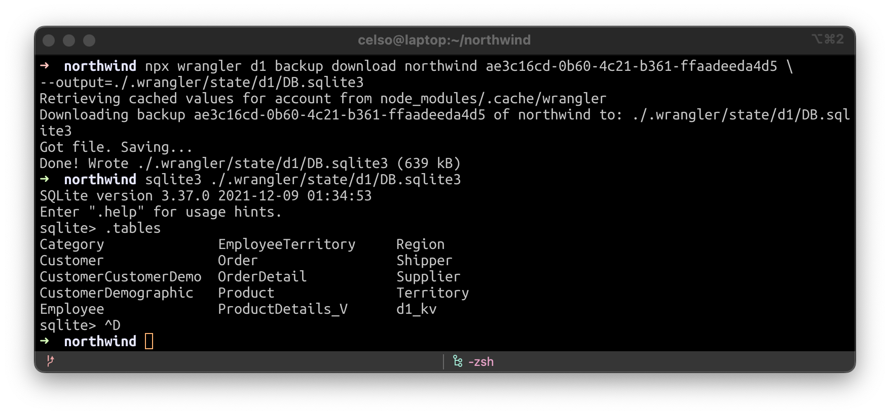
In part two, I analyze each of the problems in detail and find solutions. These issues arise because of the stateless and immutable characteristics of this solution. The next part of this article explains how to solve these issues, also it analyzes costs and performance of the solution.
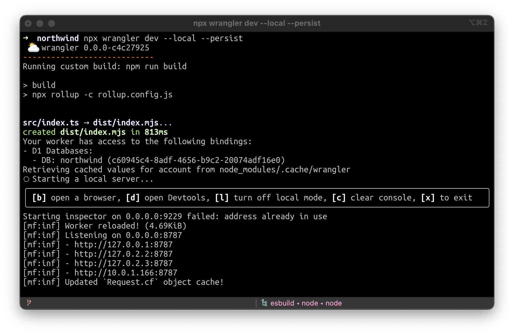
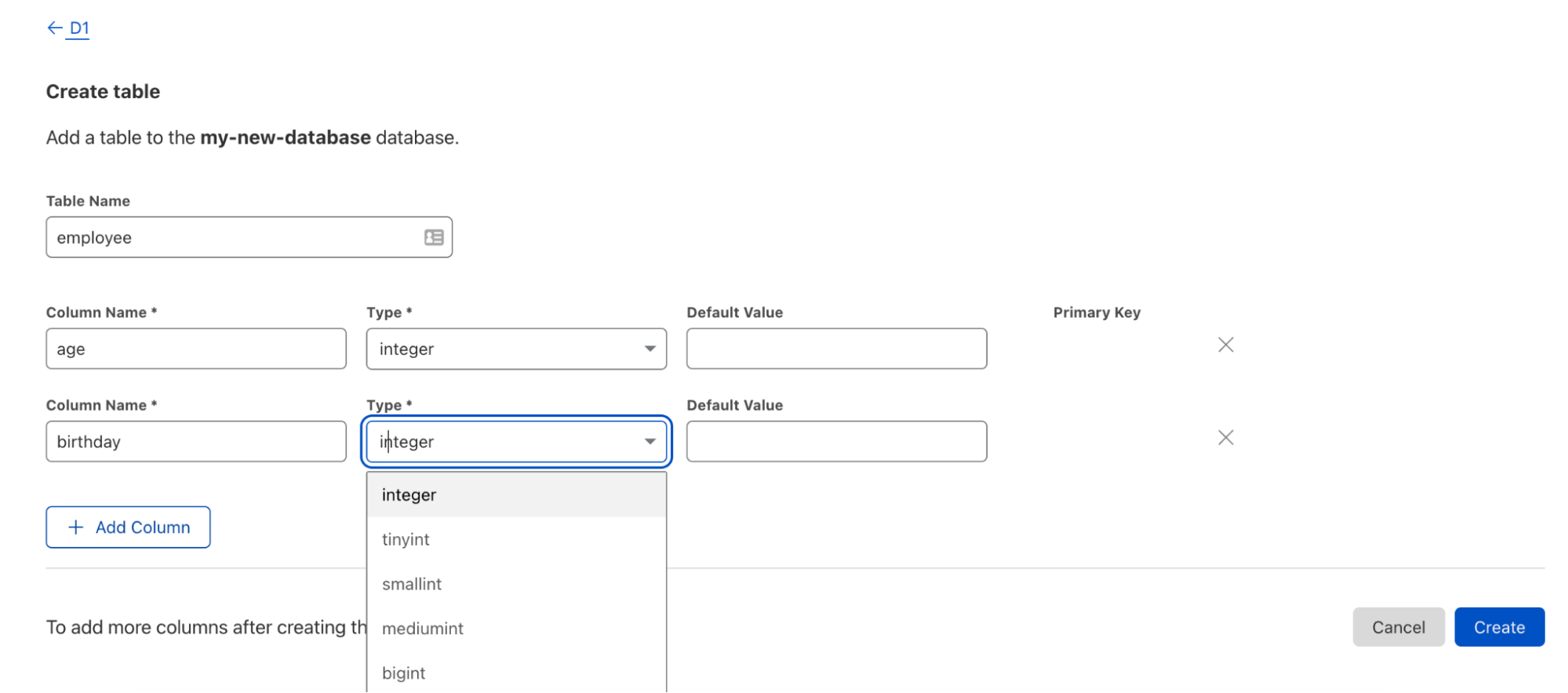
Conclusion

In this article, you learn if it is possible to migrate a non-serverless web application to a serverless environment without changing much code. You learn different tools that can help you in this process, like the AWS Lambda Web Adaptor and AWS Amplify.

If you want to see the migration in action and learn all the steps for this, there is a playlist that contains all the tutorials for you to follow and learn how this is possible.

For more serverless learning resources, visit Serverless Land.

Introducing message data protection for Amazon SNS

Post Syndicated from Julian Wood original https://aws.amazon.com/blogs/compute/introducing-message-data-protection-for-amazon-sns/

This post is written by Otavio Ferreira, Senior Software Development Manager, Marc Pinaud, Senior Product Manager, Usman Nisar, Senior Software Engineer, Hardik Vasa, Senior Solutions Architect, and Mithun Mallick, Senior Specialist Solution Architect.

Today, we are announcing the public preview release of new data protection capabilities for Amazon Simple Notification Service (SNS), message data protection. This is a new way to discover and protect sensitive data in motion at scale, without writing custom code.

SNS is a fully managed serverless messaging service. It provides topics for push-based, many-to-many pub/sub messaging for decoupling distributed systems, microservices, and event-driven serverless applications. As applications grow, so does the amount of data transmitted and the number of systems sending and receiving data. When moving data between different applications, guardrails can help you comply with data privacy regulations that require you to safeguard sensitive personally identifiable information (PII) or protected health information (PHI).

With message data protection for SNS, you can scan messages in real time for PII/PHI data and receive audit reports containing scan results. You can also prevent applications from receiving sensitive data by blocking inbound messages to an SNS topic or outbound messages to an SNS subscription. Message data protection for SNS supports a repository of over 25 unique PII/PHI data identifiers. These include people’s names, addresses, social security numbers, credit card numbers, and prescription drug codes.

These capabilities can help you adhere to a variety of compliance regulations, including HIPAA, FedRAMP, GDPR, and PCI. For more information, including the complete list of supported data identifiers, see message data protection in the SNS Developer Guide.

Overview

SNS topics enable you to integrate distributed applications more easily. As applications become more complex, it can become challenging for topic owners to manage the data flowing through their topics. Developers that publish messages to a topic may inadvertently send sensitive data, increasing regulatory risk. Message data protection enables SNS topic owners to protect sensitive application data with built-in, no-code, scalable capabilities.

To discover and protect data flowing through SNS topics with message data protection, topic owners associate data protection policies to their topics. Within these policies, you can write statements that define which types of sensitive data you want to discover and protect. As part of this, you can define whether you want to act on data flowing inbound to a topic or outbound to a subscription, which AWS accounts or specific AWS Identity and Access Management (AWS IAM) principals the policy is applicable to, and the actions you want to take on the data.

Message data protection provides two actions to help you protect your data. Auditing, to report on the amount of PII/PHI found, and blocking, to prevent the publishing or delivery of payloads that contain PII/PHI data. Once the data protection policy is set, message data protection uses pattern matching and machine learning models to scan your messages in real time for PII/PHI data identifiers and enforce the data protection policy.

For auditing, you can choose to send audit reports to Amazon Simple Storage Service (S3) for archival, Amazon Kinesis Data Firehose for analytics, or Amazon CloudWatch for logging and alarming. Message data protection does not interfere with the topic owner’s ability to use message data encryption at rest, nor with the subscriber’s ability to filter out unwanted messages using message filtering.

Applying message data protection in a use case

Consider an application that processes a variety of transactions for a set of health clinics, an organization that operates in a regulated environment. Compliance frameworks require that the organization take measures to protect both sensitive health records and financial information.

Reference architecture

The application is based on an event-driven serverless architecture. It has a data protection policy attached to the topic to audit for sensitive data and prevent downstream systems from processing certain data types.

The application publishes an event to an SNS topic every time a patient schedules a visit or sees a doctor at a clinic. The SNS topic fans out the event to two subscribed systems, billing and scheduling. Each system stores events in an Amazon SQS queue, which is processed using an AWS Lambda function.

Setting a data protection policy to an SNS topic

You can apply a data protection policy to an SNS topic using the AWS Management Console, the AWS CLI, or the AWS SDKs. You can also use AWS CloudFormation to automate the provisioning of the data protection policy.

This example uses CloudFormation to provision the infrastructure. You have two options for deploying the resources:

  • Deploy the resources by using the message data protection deploy script within the aws-sns-samples repository in GitHub.
  • Alternatively, use the following four CloudFormation templates in order. Allow time for each stack to complete before deploying the next stack, to create the following resources:

1. Prerequisites template

  • Two IAM roles with a managed policy that allows access to receive messages from the SNS topic, one for the billing and another for scheduling system, respectively.

2. Topic owner template

  • SNS topic that delivers events to two distinct systems.
  • A data protection policy that defines both auditing and blocking actions for specific types of PII and PHI.
  • S3 bucket to archive audit findings.
  • CloudWatch log group to monitor audit findings.
  • Kinesis Data Firehose to deliver audit findings to other destinations.

3. Scheduling subscriber template

  • SQS queue for the Scheduling system.
  • Lambda function for the Scheduling system.

4. Billing subscriber template

  • SQS queue for the Billing system.
  • Lambda function for the Billing system.

CloudFormation creates the following data protection policy as part of the topic owner template:

  ClinicSNSTopic:
    Type: 'AWS::SNS::Topic'
    Properties:
      TopicName: SampleClinic
      DataProtectionPolicy:
        Name: data-protection-example-policy
        Description: Policy Description
        Version: 2021-06-01
        Statement:
          - Sid: audit
            DataDirection: Inbound
            Principal:
             - '*'
            DataIdentifier:
              - 'arn:aws:dataprotection::aws:data-identifier/Address'
              - 'arn:aws:dataprotection::aws:data-identifier/AwsSecretKey'
              - 'arn:aws:dataprotection::aws:data-identifier/DriversLicense-US'
              - 'arn:aws:dataprotection::aws:data-identifier/EmailAddress'
              - 'arn:aws:dataprotection::aws:data-identifier/IpAddress'
              - 'arn:aws:dataprotection::aws:data-identifier/NationalDrugCode-US'
              - 'arn:aws:dataprotection::aws:data-identifier/PassportNumber-US'
              - 'arn:aws:dataprotection::aws:data-identifier/Ssn-US'
            Operation:
              Audit:
                SampleRate: 99
                FindingsDestination:
                  CloudWatchLogs:
                    LogGroup: !Ref AuditCWLLogs
                  Firehose:
                    DeliveryStream: !Ref AuditFirehose
                NoFindingsDestination:
                  S3:
                    Bucket: !Ref AuditS3Bucket
          - Sid: deny-inbound
            DataDirection: Inbound
            Principal:
              - '*'
            DataIdentifier:
              - 'arn:aws:dataprotection::aws:data-identifier/PassportNumber-US'
              - 'arn:aws:dataprotection::aws:data-identifier/Ssn-US'
            Operation:
              Deny: {}
          - Sid: deny-outbound-billing
            DataDirection: Outbound
            Principal:
              - !ImportValue "BillingRoleExportDataProtectionDemo"
            DataIdentifier:
              - 'arn:aws:dataprotection::aws:data-identifier/NationalDrugCode-US'
            Operation:
              Deny: {}
          - Sid: deny-outbound-scheduling
            DataDirection: Outbound
            Principal:
              - !ImportValue "SchedulingRoleExportDataProtectionDemo"
            DataIdentifier:
              - 'arn:aws:dataprotection::aws:data-identifier/Address'
              - 'arn:aws:dataprotection::aws:data-identifier/CreditCardNumber'
            Operation:
              Deny: {}

This data protection policy defines:

  • Metadata about the data protection policy, for example name, description, version, and statement IDs (sid).
  • The first statement (sid: audit) scans inbound messages from all principals for addresses, social security numbers, driver’s license, email addresses, IP addresses, national drug codes, passport numbers, and AWS secret keys.
    • The sampling rate is set to 99% so almost all messages are scanned for the defined PII/PHI.
    • Audit results with findings are delivered to CloudWatch Logs and Kinesis Data Firehose for analytics. Audit results without findings are archived to S3.
  • The second statement (sid: deny-inbound) blocks inbound messages to the topic coming from any principal, if the payload includes either a social security number or passport number.
  • The third statement (sid: deny-outbound-billing) blocks the delivery of messages to subscriptions created by the BillingRole, if the messages include any national drug codes.
  • The fourth statement (sid: deny-outbound-scheduling) blocks the delivery of messages to subscriptions created by the SchedulingRole, if the messages include any credit card numbers or addresses.

Testing the capabilities

Test the message data protection capabilities using the following steps:

  1. Publish a message without PII/PHI data to the Clinic Topic. In the CloudWatch console, navigate to the log streams of the respective Lambda functions to confirm that the message is delivered to both subscribers. Both messages are delivered because the payload contains no sensitive data for the data protection policy to deny. The log message looks as follows:
    "This is a demo! received from queue arn:aws:sqs:us-east-1:111222333444:Scheduling-SchedulingQueue"
  2. Publish a message with a social security number (try ‘SSN: 123-12-1234’) to the Clinic Topic. The request is denied, and an audit log is delivered to your CloudWatch Logs log group and Firehose delivery stream.
  3. Navigate to the CloudWatch log console and confirm that the audit log is visible in the /aws/vendedlogs/clinicaudit CloudWatch log group. The following example shows that the data protection policy (sid: deny-inbound) denied the inbound message as the payload contains a US social security number (SSN) between the 5th and the 15th character.
    {
        "messageId": "77ec5f0c-5129-5429-b01d-0457b965c0ac",
        "auditTimestamp": "2022-07-28T01:27:40Z",
        "callerPrincipal": "arn:aws:iam::111222333444:role/Admin",
        "resourceArn": "arn:aws:sns:us-east-1:111222333444:SampleClinic",
        "dataIdentifiers": [
            {
                "name": "Ssn-US",
                "count": 1,
                "detections": [
                    {
                        "start": 5,
                        "end": 15
                    }
                ]
            }
        ]
    }
    
  4. You can use the CloudWatch metrics, MessageWithFindings and MessageWithNoFindings, to track how frequently PII/PHI data is published to an SNS topic. Here’s an example of what the CloudWatch metric graph looks like as the amount of sensitive data published to a topic varies over time:
    CloudWatch metric graph
  5. Publish a message with an address (try ‘410 Terry Ave N, Seattle 98109, WA’). The request is only delivered to the Billing subscription. The data protection policy (sid: deny-outbound-scheduling) denies the outbound message to the Scheduling subscription as the payload contains an address.
  6. Confirm that the message is only delivered to the Billing Lambda function by navigating to the CloudWatch console and inspecting the logs of the two respective Lambda functions. The CloudWatch log of the Billing Lambda function contains the sensitive message that was delivered to it as it was an authorized subscriber. Here’s an example of what the log contains:410 Terry Ave N, Seattle 98109, WA received from queue arn:aws:sqs:us-east-1:111222333444:Billing-BillingQueue
  7. Publish a message with a drug code (try ‘NDC: 0777-3105-02’). The request is only delivered to the Scheduling subscription. The data protection policy (sid: deny-outbound-billing) denies the outbound message to the Billing subscription as the payload contains a drug code.
  8. Confirm that the message is only delivered to the Scheduling Lambda function by navigating to the CloudWatch console and inspecting the logs of the two respective Lambda functions. The CloudWatch log of the Scheduling Lambda function contains the sensitive message that was delivered to it as it was an authorized subscriber. Here’s an example of what the log contains:
    NDC: 0777-3105-02 received from queue arn:aws:sqs:us-east-1:111222333444:Scheduling-SchedulingQueue

Cleaning up

After testing, avoid incurring usage charges by deleting the resources that you created. Navigate to the CloudFormation console and delete the four CloudFormation stacks that you created during the walkthrough. Remember, you must delete all the objects from the S3 bucket before deleting the stack.

Conclusion

This post shows how message data protection enables a topic owner to discover and protect sensitive data that is exchanged through SNS topics. The example shows how to create a data protection policy that generates audit reports for sensitive data and blocks messages from delivery to specific subscribers if the payload contains sensitive data.

Get started with SNS and message data protection by using the AWS Management Console, AWS Command Line Interface (CLI), AWS SDKs, or CloudFormation.

For more details, see message data protection in the SNS Developer Guide. For information on pricing, see SNS pricing.

For more serverless learning resources, visit Serverless Land.