Post Syndicated from Crosstalk Solutions original https://www.youtube.com/watch?v=gpCZ4NJ39gg
Integrate AWS IAM Identity Center (successor to AWS Single Sign-On) with AWS Lake Formation fine-grained access controls
Post Syndicated from Benon Boyadjian original https://aws.amazon.com/blogs/big-data/integrate-aws-iam-identity-center-successor-to-aws-single-sign-on-with-aws-lake-formation-fine-grained-access-controls/
Data lakes are a centralized repository for storing structured and unstructured data at scale. Data lakes enable you to create dashboards, perform big data processing and real-time analytics, and create machine learning (ML) models on your data to drive business decisions.
Many customers are choosing AWS Lake Formation as their data lake management solution. Lake Formation is an integrated data lake service that makes it simple for you to ingest, clean, catalog, transform, and secure your data and make it available for analysis and ML.
However, some companies require account authentication and authorization to be managed through AWS IAM Identity Center (successor to AWS Single Sign-On), which doesn’t have a built-in integration with Lake Formation.
Integrating Lake Formation with IAM Identity Center can help you manage data access at the organization level, consolidating AWS account and data lake authentication and authorization.
In this post, we walk through the steps to integrate IAM Identity Center with Lake Formation.
Solution overview
In this post, we configure IAM Identity Center with permission sets for your data lake personas. These are the permissions that allow your data lake users to access Lake Formation. When the permission sets are assigned to your data lake account, IAM Identity Center creates Identity and Access Management (IAM) roles in that account. The IAM roles are prefixed with AWSReservedSSO_<Permission Set Name>.
In Lake Formation, you can grant data resource permissions to IAM users and roles. To integrate with IAM Identity Center, you will grant data resource access to the IAM roles created by IAM Identity Center.
Now, when users access the data lake account through the IAM Identity Center portal, they assume an IAM role that has access to Lake Formation resources.
The following diagram illustrates this solution architecture.

To implement the solution, complete the following high-level steps:
- Create a permission set within IAM Identity Center
- Grant Users or Groups access to the data lake account in IAM Identity Center
- Assign an IAM Identity Center role as a Data Lake Administrator
- Grant IAM Identity Center generated IAM role data lake permissions in Lake Formation
- Grant IAM Identity Center generated IAM role data location permissions in Lake Formation
Prerequisites
For this walkthrough, you should have the following prerequisites:
- Have AWS Organizations set up (for instructions, refer to How do I get started with AWS Organizations?)
- Configure IAM Identity Center
- Verify that your Lake Formation data lake account is part of your organization
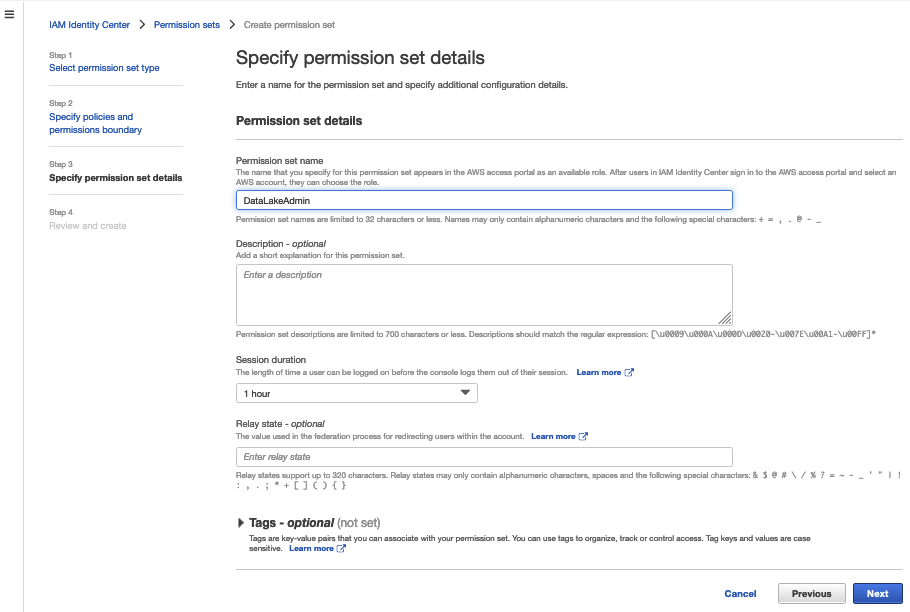
Create a permission set with IAM Identity Center
To create your permission set, complete the following steps:
- Sign into the AWS Management Console with your management account and go to the Region where IAM Identity Center is configured.
- On the IAM Identity Center Console, choose Permissions sets in the navigation pane.
- Choose Create permission set.

- Select Custom permission set, then choose Next.

- Next, you must specify policies. The first permission set you create should have data lake admin privileges.
AWS recommends granting data lake admins the following AWS managed policies:AWSGlueConsoleFullAccess,AWSLakeFormationCrossAccountManager,AWSLakeFormationDataAdmin,AmazonAthenaFullAccess, andCloudWatchLogsReadOnlyAccess. However, if these permissions are too permissive or not permissive enough, you may prefer using customer managed policies.

- Choose Next
- Specify permission set details, then choose Next.

- Review your settings, then choose Create.


Repeat the steps to create a data analyst role to grant Lake Formation access. For this post, we created the role LakeFormationDataAnalyst with the policy AmazonAthenaFullAccess.
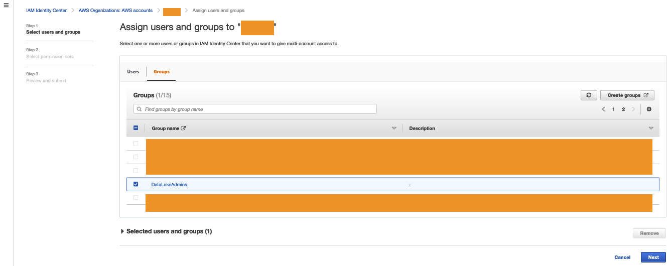
Grant users or groups access to the data lake account in IAM Identity Center
To grant access to users and groups, complete the following steps:
- On the IAM Identity Center console, chose AWS accounts in the navigation pane.
- Choose Assign users or groups.

- Select the user or group you want to assign the data lake account permissions to (
DataLakeAdmin). - Choose Next.

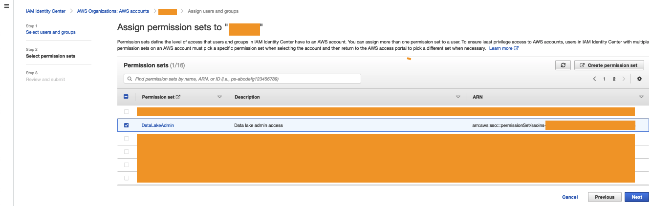
- Select the permission you created earlier.
- Choose Next.

- Review your settings, then choose Submit.


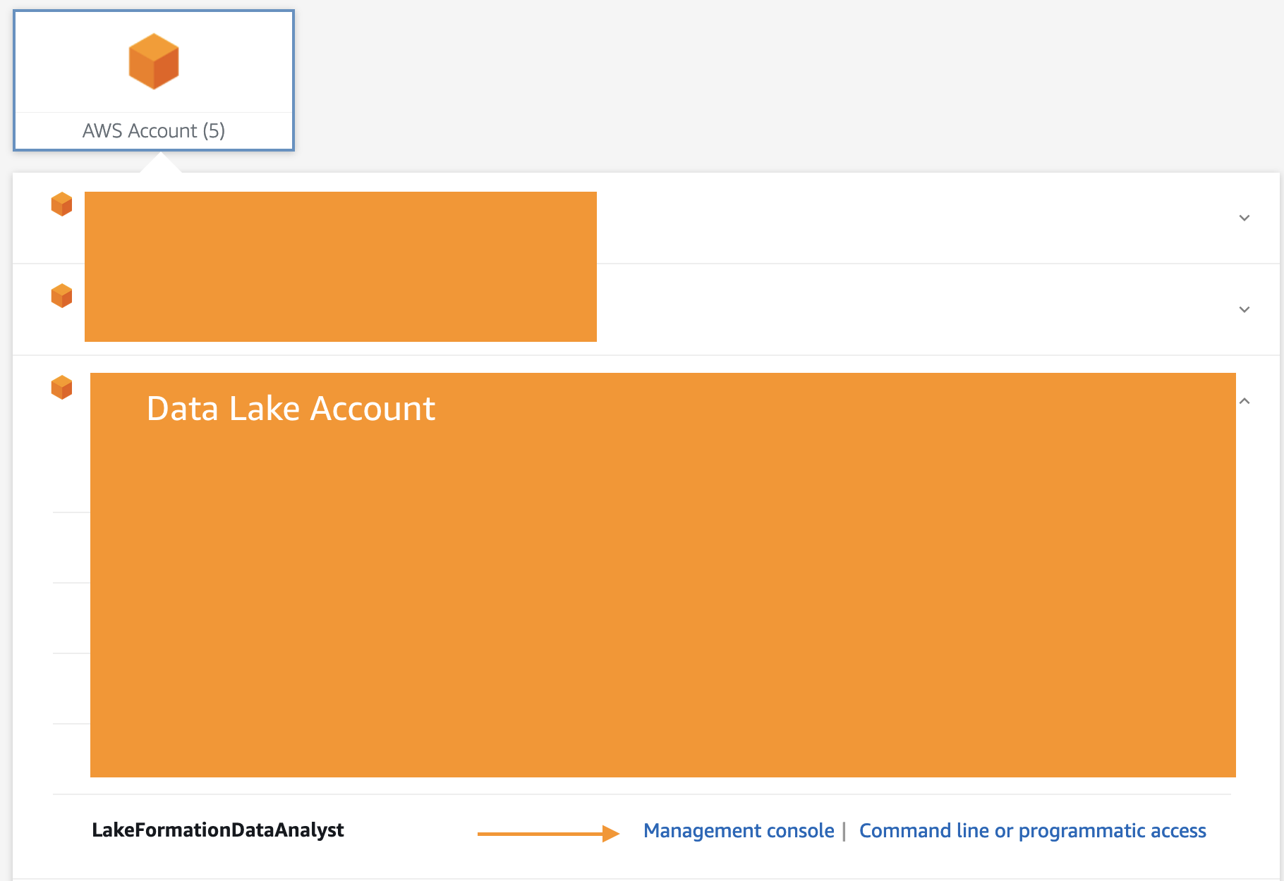
Verify your IAM Identity Center permissions have been successfully granted by visiting your IAM Identity Center Portal, choosing the data lake admin, and signing in to the console.

Assign an IAM Identity Center role as a data lake administrator
The following steps set up a data lake administrator with the IAM role created by IAM Identity Center. Administrators have full access to the Lake Formation console, and control the initial data configuration and access permissions. For all users and groups that don’t need to be data lake administrators, skip to the next series of steps.
- Sign in to the console as the data lake account with admin access.
- Open the Lake Formation console.A pop-up window appears, prompting you to define your administrators.
- Select Add other AWS users or roles.
- Choose the permission set you created earlier (starting with
AWSReservedSSO_DataLakeAdmin). - Choose Get started.

- On the Administrative roles and tasks page, under Database creators, choose Grant.

- Choose your data lake admin role.
- Select Create database under Catalog permissions and Grantable permissions.
- Choose Grant.


You now have an IAM Identity Center-generated IAM principal that is assigned as the data lake administrator and database creator.
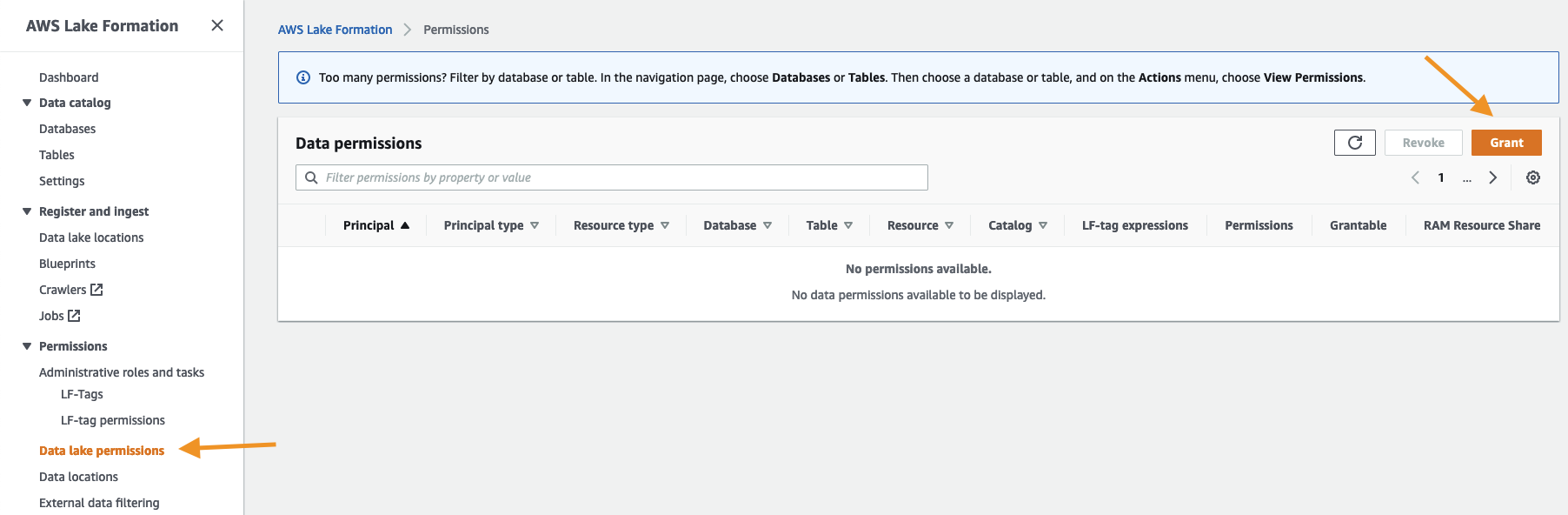
Grant the IAM Identity Center role data lake permissions in Lake Formation
You now manage data lake permissions. For more information, refer to Managing Lake Formation permissions.
Whether you’re managing permissions with LF-tags or named resources, the steps for granting access remain the same
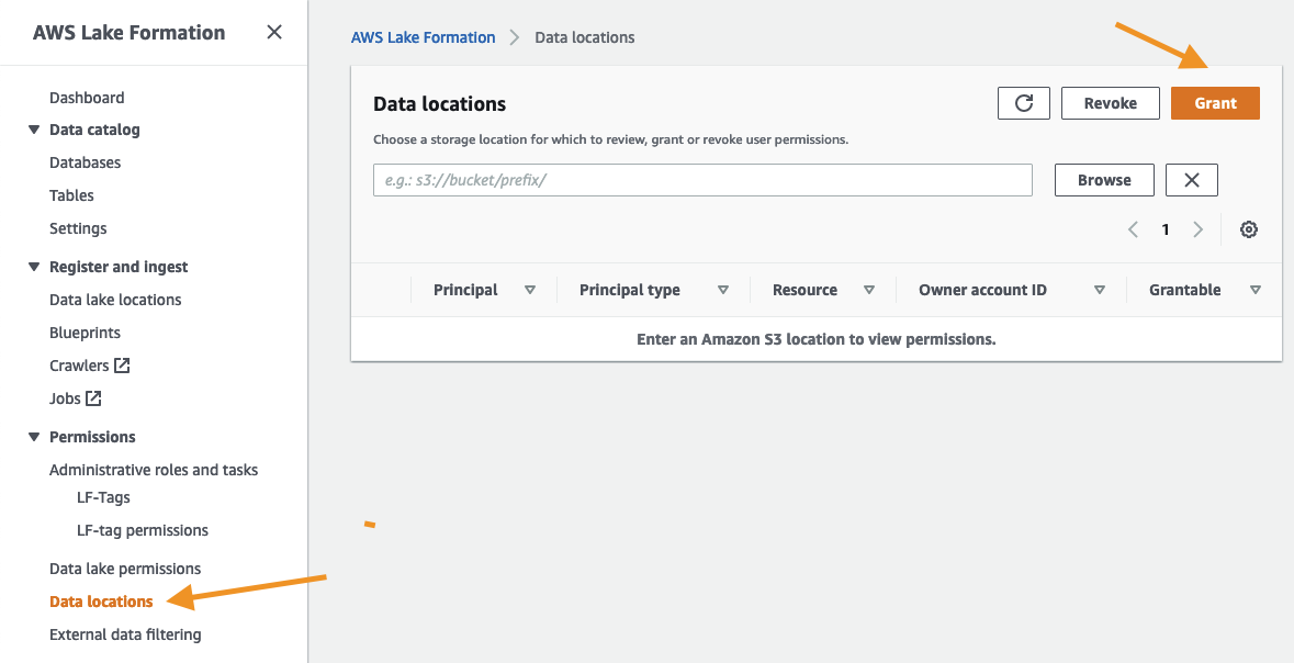
- On the Lake Formation console, under Permissions in the navigation pane, choose Data lake permissions.
- Choose Grant.

- Select IAM users and roles.
- Choose the
AWSReservedSSO_LakeFormationDataAnalystrole. - Grant access to database and table permissions as applicable, then choose Grant.


You now have an IAM Identity Center-generated IAM principal data permissions.
Grant the IAM Identity Center role data location permissions in Lake Formation
When granting access to data locations, the process remains the same.
- On the Lake Formation console, under Permissions in the navigation pane, choose Data locations.
- Choose Grant.

- Choose the
AWSReservedSSO_LakeFormationDataAnalystrole. - Complete the remaining fields and choose Grant.


You now have an IAM Identity Center-generated IAM principal with Data location access.
Validate data access
We now validate data access for the IAM Identity Center principal.
- Sign in to the console through IAM Identity Center as the principal you granted access to. For this post, we’re logging in as the
LakeFormationDataAnalystrole.

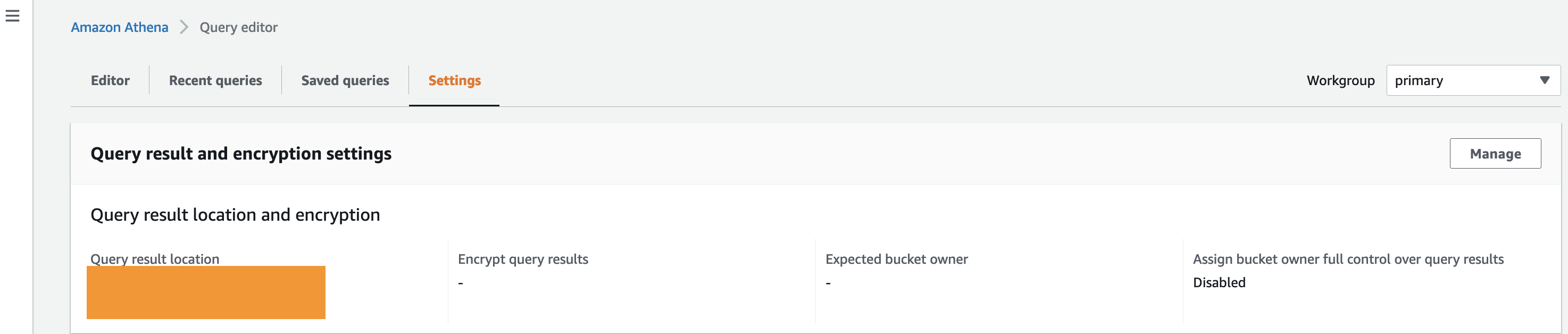
To test data access, we run some queries in Amazon Athena. - On the Athena console, choose Query editor.
- On the Settings tab, confirm that a query result location is set up.

- If you don’t have a query result location, choose Manage and configure your query result location and encryption.

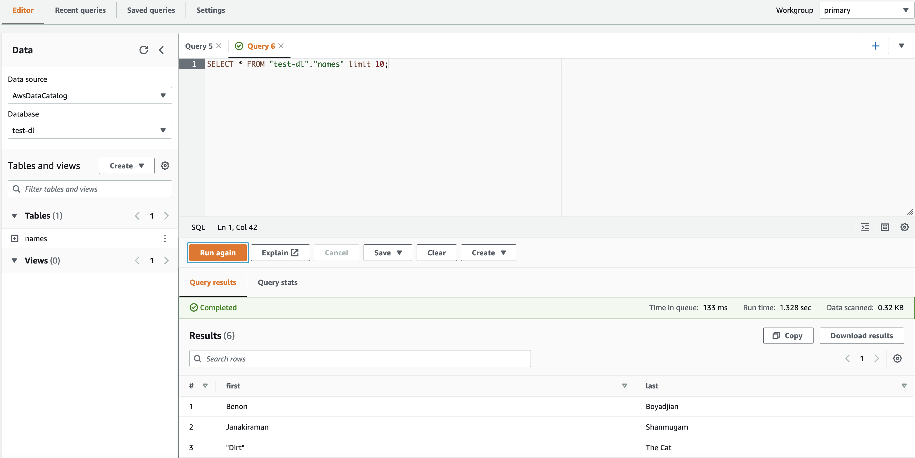
- In the Athena query editor, on the Editor tab, choose the database that you granted access to.If the principal doesn’t have access to the Lake Formation table and data location, you won’t be able to view data in Athena.
- Choose the menu icon next to your table and choose Generate table DDL.


Confirm that the data appears on the Query results tab.
Conclusion
In this post, we demonstrated how to integrate IAM Identity Center with Lake Formation permissions. You can now grant IAM Identity Center identities administrator, database creation, database and table, and data location access in Lake Formation. Managing data lake permissions through IAM Identity Center allows you to control data access from your management account, helping to improve your scalability and security.
If you’re wondering how to adapt this solution to Tag-based access control, read Easily manage your data lake at scale using AWS Lake Formation Tag-based access control and apply the techniques you learned from this blog.
About the authors
 Benon Boyadjian is a Private Equity Solutions Architect at AWS. He is passionate about helping customers understand the impact AWS can have on their businesses and guiding their AWS implementations. In his free time, he enjoys swimming, snowboarding, and playing with his cat Dirt.
 Janakiraman Shanmugam is a Senior Data Architect at Amazon Web Services . He has a focus in Data & Analytics and enjoys helping customers to solve Big data & machine learning problems. Outside of the office, he loves to be with his friends and family and spend time outdoors.
Baxter SIGMA Spectrum Infusion Pumps: Multiple Vulnerabilities (FIXED)
Post Syndicated from Deral Heiland original https://blog.rapid7.com/2022/09/08/baxter-sigma-spectrum-infusion-pumps-multiple-vulnerabilities-fixed/

Rapid7, Inc. (Rapid7) discovered vulnerabilities in two TCP/IP-enabled medical devices produced by Baxter Healthcare. The affected products are:
- SIGMA Spectrum Infusion Pump (Firmware Version 8.00.01)
- SIGMA Wi-Fi Battery (Firmware Versions 16, 17, 20 D29)
Rapid7 initially reported these issues to Baxter on April 20, 2022. Since then, members of our research team have worked alongside the vendor to discuss the impact, resolution, and a coordinated response for these vulnerabilities.
Product description
Baxter’s SIGMA Spectrum product is a commonly used brand of infusion pumps, which are typically used by hospitals to deliver medication and nutrition directly into a patient’s circulatory system. These TCP/IP-enabled devices deliver data to healthcare providers to enable more effective, coordinated care.
Credit
The vulnerabilities in two TCP/IP-enabled medical devices were discovered by Deral Heiland, Principal IoT Researcher at Rapid7. They are being disclosed in accordance with Rapid7’s vulnerability disclosure policy after coordination with the vendor.
Vendor statement
“In support of our mission to save and sustain lives, Baxter takes product security seriously. We are committed to working with the security researcher community to verify and respond to legitimate vulnerabilities and ask researchers to participate in our responsible reporting process. Software updates to disable Telnet and FTP (CVE-2022-26392) are in process. Software updates to address the format string attack (CVE-2022-26393) are addressed in WBM version 20D30 and all other WBM versions. Authentication is already available in Spectrum IQ (CVE-2022-26394). Instructions to erase all data and settings from WBMs and pumps before decommissioning and transferring to other facilities (CVE-2022-26390) are in process for incorporation into the Spectrum Operator’s Manual and are available in the Baxter Security Bulletin.”
Exploitation and remediation
This section details the potential for exploitation and our remediation guidance for the issues discovered and reported by Rapid7, so that defenders of this technology can gauge the impact of, and mitigations around, these issues appropriately.
Battery units store Wi-Fi credentials (CVE-2022-26390)
Rapid7 researchers tested Spectrum battery units for vulnerabilities. We found all units that were tested store Wi-Fi credential data in non-volatile memory on the device.
When a Wi-Fi battery unit is connected to the primary infusion pump and the infusion pump is powered up, the pump will transfer the Wi-Fi credential to the battery unit.
Exploitation
An attacker with physical access to an infusion pump could install a Wi-Fi battery unit (easily purchased on eBay), and then quickly power-cycle the infusion pump and remove the Wi-Fi battery – allowing them to walk away with critical Wi-Fi data once a unit has been disassembled and reverse-engineered.
Also, since these battery units store Wi-Fi credentials in non-volatile memory, there is a risk that when the devices are de-acquisitioned and no efforts are made to overwrite the stored data, anyone acquiring these devices on the secondary market could gain access to critical Wi-Fi credentials of the organization that de-acquisitioned the devices.
Remediation
To mitigate this vulnerability, organizations should restrict physical access by any unauthorized personnel to the infusion pumps or associated Wi-Fi battery units.
In addition, before de-acquisitioning the battery units, batteries should be plugged into a unit with invalid or blank Wi-Fi credentials configured and the unit powered up. This will overwrite the Wi-Fi credentials stored in the non-volatile memory of the batteries. Wi-Fi must be enabled on the infusion pump unit for this overwrite to work properly.
Format string vulnerabilities
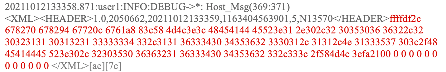
“Hostmessage” (CVE-2022-26392)
When running a telnet session on the Baxter Sigma Wi-Fi Battery Firmware Version 16, the command “hostmessage” is vulnerable to format string vulnerability.
Exploitation
An attacker could trigger this format string vulnerability by entering the following command during a telnet session:

To view the output of this format string vulnerability, `settrace state=on` must be enabled in the telnet session. `set trace` does not need to be enabled for the format string vulnerability to be triggered, but it does need to be enabled if the output of the vulnerability is to be viewed.
Once `set trace` is enabled and showing output within the telnet session screen, the output of the vulnerability can be viewed, as shown below, where each `%x` returned data from the device’s process stack.
SSID (CVE-2022-26393)
Rapid7 also found another format string vulnerability on Wi-Fi battery software version 20 D29. This vulnerability is triggered within SSID processing by the `get_wifi_location (20)` command being sent via XML to the Wi-Fi battery at TCP port 51243 or UDP port 51243.

Exploitation
This format string vulnerability can be triggered by first setting up a Wi-Fi access point containing format string specifiers in the SSID. Next, an attacker could send a `get_wifi_location (20)` command via TCP Port 51243 or UDP port 51243 to the infusion pump. This causes the device to process the SSID name of the access point nearby and trigger the exploit. The results of the triggering of format strings can be viewed with trace log output within a telnet session as shown below.
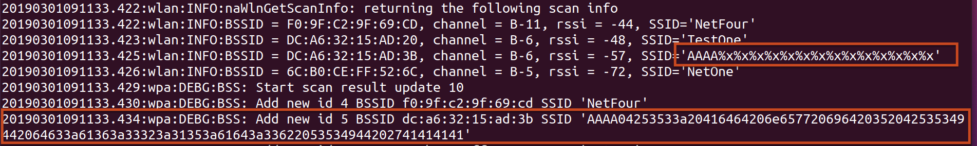
The SSID of `AAAA%x%x%x%x%x%x%x%x%x%x%x%x%x%x` allows for control of 4 bytes on the stack, as shown above, using the `%x` to walk the stack until it reaches 41414141. By changing the leading `AAAA` in the SSID, a malicious actor could potentially use the format string injection to read and write arbitrary memory. At a minimum, using format strings of `%s` and `%n` could allow for a denial of service (DoS) by triggering an illegal memory read (`%s`) and/or illegal memory write (`%n`).
Note that in order to trigger this DoS effect, the attacker would need to be within normal radio range and either be on the device’s network or wait for an authorized `get_wifi_location` command (the latter would itself be a usual, non-default event).
Remediation
To prevent exploitation, organizations should restrict access to the network segments containing the infusion pumps. They should also monitor network traffic for any unauthorized host communicating over TCP and UDP port 51243 to infusion pumps. In addition, be sure to monitor Wi-Fi space for rogue access points containing format string specifiers within the SSID name.
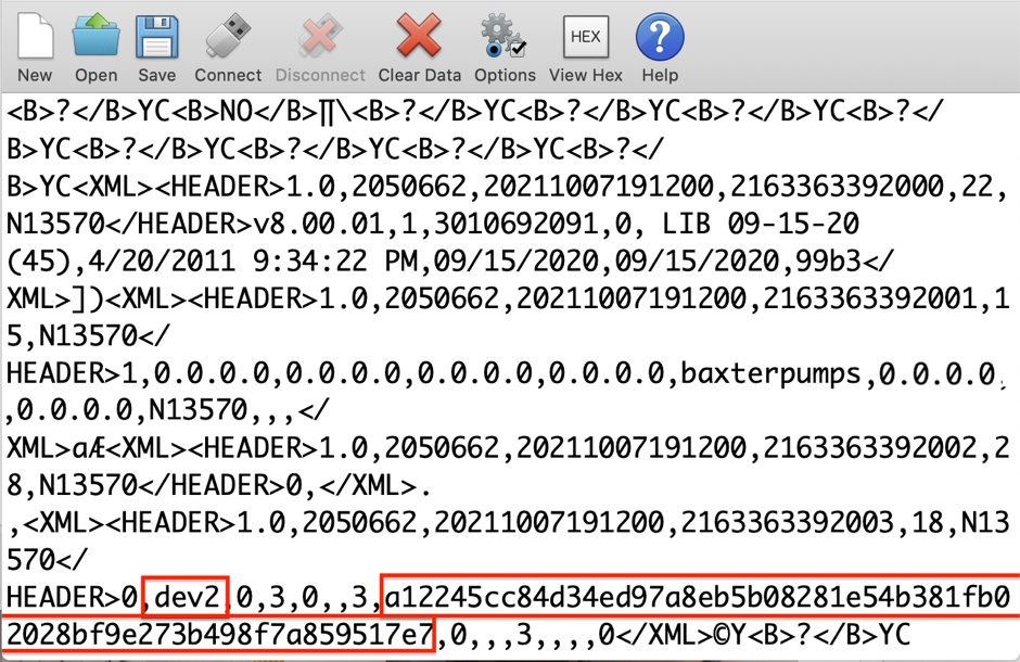
Unauthenticated network reconfiguration via TCP/UDP (CVE-2022-26394)
All Wi-Fi battery units tested (versions 16, 17, and 20 D29) allowed for remote unauthenticated changing of the SIGMA GW IP address. The SIGMA GW setting is used for configuring the back-end communication services for the devices operation.
Exploitation
An attacker could accomplish a remote redirect of SIGMA GW by sending an XML command 15 to TCP or UDP port 51243. During testing, only the SIGMA GW IP was found to be remotely changeable using this command. An example of this command and associated structure is shown below:
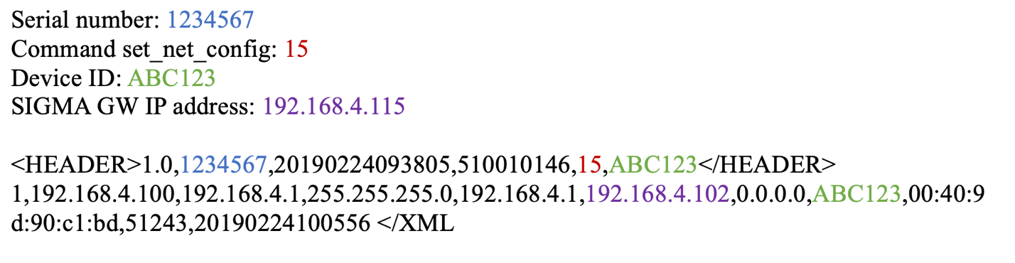
This could be used by a malicious actor to man-in-the-middle (MitM) all the communication initiated by the infusion pump. This could lead to information leakage and/or data being manipulated by a malicious actor.
Remediation
Organizations using SIGMA Spectrum products should restrict access to the network segments containing the infusion pumps. They should also monitor network traffic for any unauthorized host communicating over TCP and UDP port 51243 to the infusion pumps.
UART configuration access to Wi-Fi configuration data (additional finding)
The SIGMA Spectrum infusion pump unit transmits data unencrypted to the Wi-Fi battery unit via universal asynchronous receiver-transmitter (UART). During the power-up cycle of the infusion pump, the first block of data contains the Wi-Fi configuration data. This communication contains the SSID and 64-Character hex PSK.
Exploitation
A malicious actor with physical access to an infusion pump can place a communication shim between the units (i.e., the pump and the Wi-Fi battery) and capture this data during the power-up cycle of the unit.

Remediation
To help prevent exploitation, organizations should restrict physical access by unauthorized persons to the infusion pumps and associated Wi-Fi battery units.
Note that this is merely an additional finding based on physical, hands-on access to the device. While Baxter has addressed this finding through better decommissioning advice to end users, this particular issue does not rank for its own CVE identifier, as local encryption is beyond the scope of the hardware design of the device.
Disclosure timeline
Baxter is an exemplary medical technology company with an obvious commitment to patient and hospital safety. While medtech vulnerabilities can be tricky and expensive to work through, we’re quite pleased with the responsiveness, transparency, and genuine interest shown by Baxter’s product security teams.
- April, 2022: Issues discovered by Deral Heiland of Rapid7
- Wed, April 20, 2022: Issues reported to Baxter product security
- Wed, May 11, 2022: Update requested from Baxter
- Wed, Jun 1, 2022: Teleconference with Baxter and Rapid7 presenting findings
- Jun-Jul 2022: Several follow up conversations and updates between Baxter and Rapid7
- Tue, Aug 2, 2022: Coordination tracking over VINCE and more teleconferencing involving Baxter, Rapid7, CERT/CC, and ICS-CERT (VU#142423)
- Wed, Aug 31, 2022: Final review of findings and mitigations
- Thu Sep 8, 2022: Baxter advisory published
- Thu, Sep 8, 2022: Public disclosure of these issues
- Thu, Sep 8, 2022: ICS-CERT advisory published
Additional reading:
- Rapid7 Discovered Vulnerabilities in Cisco ASA, ASDM, and FirePOWER Services Software
- CVE-2022-31660 and CVE-2022-31661 (FIXED): VMware Workspace ONE Access, Identity Manager, and vRealize Automation LPE
- QNAP Poisoned XML Command Injection (Silently Patched)
- Primary Arms PII Disclosure via IDOR (FIXED)
Facebook Has No Idea What Data It Has
Post Syndicated from Bruce Schneier original https://www.schneier.com/blog/archives/2022/09/facebook-has-no-idea-what-data-it-has.html
This is from a court deposition:
Facebook’s stonewalling has been revealing on its own, providing variations on the same theme: It has amassed so much data on so many billions of people and organized it so confusingly that full transparency is impossible on a technical level. In the March 2022 hearing, Zarashaw and Steven Elia, a software engineering manager, described Facebook as a data-processing apparatus so complex that it defies understanding from within. The hearing amounted to two high-ranking engineers at one of the most powerful and resource-flush engineering outfits in history describing their product as an unknowable machine.
The special master at times seemed in disbelief, as when he questioned the engineers over whether any documentation existed for a particular Facebook subsystem. “Someone must have a diagram that says this is where this data is stored,” he said, according to the transcript. Zarashaw responded: “We have a somewhat strange engineering culture compared to most where we don’t generate a lot of artifacts during the engineering process. Effectively the code is its own design document often.” He quickly added, “For what it’s worth, this is terrifying to me when I first joined as well.”
[…]
Facebook’s inability to comprehend its own functioning took the hearing up to the edge of the metaphysical. At one point, the court-appointed special master noted that the “Download Your Information” file provided to the suit’s plaintiffs must not have included everything the company had stored on those individuals because it appears to have no idea what it truly stores on anyone. Can it be that Facebook’s designated tool for comprehensively downloading your information might not actually download all your information? This, again, is outside the boundaries of knowledge.
“The solution to this is unfortunately exactly the work that was done to create the DYI file itself,” noted Zarashaw. “And the thing I struggle with here is in order to find gaps in what may not be in DYI file, you would by definition need to do even more work than was done to generate the DYI files in the first place.”
The systemic fogginess of Facebook’s data storage made answering even the most basic question futile. At another point, the special master asked how one could find out which systems actually contain user data that was created through machine inference.
“I don’t know,” answered Zarashaw. “It’s a rather difficult conundrum.”
I’m not surprised. These systems are so complex that no humans understand them anymore. That allows us to do things we couldn’t do otherwise, but it’s also a problem.
EDITED TO ADD: Another article.
Handy Tips #37: Collecting metrics from HTTP endpoints with HTTP agent items
Post Syndicated from Arturs Lontons original https://blog.zabbix.com/handy-tips-37-collecting-metrics-from-http-endpoints-with-http-agent-items/23160/
The post Handy Tips #37: Collecting metrics from HTTP endpoints with HTTP agent items appeared first on Zabbix Blog.
Security updates for Thursday
Post Syndicated from original https://lwn.net/Articles/907508/
Security updates have been issued by Debian (libgoogle-gson-java), Fedora (autotrace, insight, and open-vm-tools), Oracle (open-vm-tools), Red Hat (open-vm-tools, openvswitch2.13, openvswitch2.15, openvswitch2.16, openvswitch2.17, ovirt-host, and rh-nodejs14-nodejs and rh-nodejs14-nodejs-nodemon), Scientific Linux (open-vm-tools), Slackware (python3), SUSE (clamav, gdk-pixbuf, gpg2, icu, ImageMagick, java-1_8_0-ibm, libyajl, mariadb, udisks2, webkit2gtk3, and yast2-samba-provision), and Ubuntu (dnsmasq).
VeloCON 2022: Digging Deeper Together!
Post Syndicated from Carlos Canto original https://blog.rapid7.com/2022/09/08/velocon-2022-digging-deeper-together/

September 15, 2022 | Live at 9 am EDT | Virtual and Free

Join the open-source digital forensics and incident response (DFIR) community for a day-long, virtual summit as we DIG DEEPER TOGETHER!
Have you ever wanted to share your passion and interest in Velociraptor with the rest of the community? VeloCON is your chance! Come together with other DFIR experts and enthusiasts from around the world on September 15th as we delve into new ideas, workflows, and features that will take Velociraptor to the next level of endpoint management, detection, and response.
The first annual VeloCON summit will be held Thursday Sept 15th, 2022 at 9 am EDT. It is a 1-day event focused on the Velociraptor community – a forum to share experiences in using and developing Velociraptor to address the needs of the wider DFIR community. This year, the conference will be online and completely free! User-created presentations will be streamed live via Zoom webinar and on the Velociraptor YouTube channel, and will be archived on our Velociraptor website.
Registration is completely free. Here is the speaker list and agenda at a glance:

We look forward to seeing you at VeloCON. If you can’t make the event live, be sure to catch a replay of the event, which we’ll have posted to our website and YouTube channel.
Register for VeloCON today! Learn more about Velociraptor by visiting any of our web and social media channels below:
Additional reading:
- [The Lost Bots] S02E03: Browser-in-Browser Attacks — Don’t Get (Cat)-Phished
- Cybersecurity Analysts: Job Stress Is Bad, but Boredom Is Kryptonite
- OCSF: Working Together to Standardize Data
- Velociraptor Version 0.6.5: Table Transformations, Multi-Lingual Support, and Better VQL Error-Handling Let You Dig Deeper Than Ever
Backblaze Rides the Nautilus Data Center Wave
Post Syndicated from original https://www.backblaze.com/blog/backblaze-rides-the-nautilus-data-center-wave/
On the outside and on the inside, our newest data center (DC) is more than a little different: there are no cooling towers chugging on the roof, no chillers, or coolants at all. No, we’re not doing a drive stats experiment on how well data centers run at 54° Celsius. This data center, owned and developed by Nautilus Data Technologies, is nice and cool inside. Built with a unique mix of proven maritime and industrial water-cooling technologies that use river water to cool everything inside—racks, servers, switches, and people—this new DC is innovative, environmentally awesome, secure, fascinating, and other such words and phrases, all rolled into one. And it just happens to be located on a barge on a river in California.
It’s a unique setup, one that might raise a few eyebrows. It certainly did for us. But once our team dug in, we didn’t just find room for another exabyte of data, we found an extremely resilient data center that supports our durability requirements and decreases our environmental impact of providing you cloud storage. You can do a deep dive into the Nautilus technology on their website, but of course I needed to make my own visit to look into this shiny new tech on my own. What follows is an overview of what I learned: how the technology works and why we decided to make the Nautilus data center part of our cloud storage platform.

Nautilus Data Center Overview
In the Port of Stockton in California, an odd looking barge is moored next to the shore of the San Joaquin River. If you were able to get close enough, you might notice the massive mooring poles the barge is attached to. And if you were a student of such things, you might recognize these mooring poles as having the same rating as the mooring poles whose attached boats and barges survived hurricane Katrina. The barge isn’t going anywhere.
Above deck are the data center halls. Once inside, it feels like, well, a data center—almost. The power distribution units (PDUs) and other power-related equipment hum quietly and racks of servers and networking gear are lined up across the floor, but there are no hot and cold aisles, and no air conditioning grates or ductwork either. Instead the ceiling is lined with an orderly arrangement of pipes carrying water that’s been cooled by the river outside.
Upriver from the data center, water is collected from the river and filtered before running through the heat exchanger that cools water circulating in a closed loop inside the data center. River water never enters the data center hall.
The technology used to collect and filter the water has been used for decades in power plants, submarines, aircraft carriers, and so on. The entire collection system is marine wildlife-friendly and certified by multiple federal and state agencies, commissions, and water boards, including the California Department of Fish and Wildlife. One of the reasons Nautilus chose the Port of Stockton was the truism that, if you can get something certified for operation in the state of California, then you can typically get it certified pretty much anywhere.

Inside the data center, at specific intervals, water supply and return lines run down to the rear door on each rack. The server fans expel hot air through the rear door and the water inside the door removes the heat to deliver cool air into the room. We use ColdLogik Rear Door Coolers to perform the heat exchange process. The closed loop water system is under vacuum—meaning that it’s leak proof, so water will never touch the servers. A nice bit of innovation by the Nautilus designers and engineers.
Downriver from the data center, the water is discharged. The water can be up to 4° Fahrenheit warmer than when it started upriver. As we mentioned before, the various federal and state authorities worked with Nautilus engineers to select a discharge location which was marine wildlife-friendly. Within seconds of being discharged the water is back to river temperature and continues its journey to the Sacramento Delta. The water spends less than 15 seconds end-to-end in the system which operates with no additional water, uses no chemicals, and adds zero pollutants to the river.
Why Nautilus
For Backblaze, the process of choosing a data center location is a bit more rigorous than throwing a dart at a map and putting some servers there. Our due diligence checklist is long and thorough, taking into consideration redundancy, capacity, scalability, cost, network providers, power providers, stability of the data center owner, and so on. The Nautilus facility passed all of our tests and will enable us to store over an exabyte of data on-site to optimize our operational scalability. In addition, the Nautilus relationship brings us a few additional benefits not traditionally heard of when talking about data centers.
Innovation
Storage Pods, Drive Farming, Drive Stats, and even Backblaze B2 Cloud Storage are all innovations in their own way as they changed market dynamics or defined a different way to do things. They all have in common the trait of putting together proven ideas and technologies in a new way that adds value to the marketplace. In this case, Nautilus marries proven maritime and industrial water cooling and distribution technologies with a new approach to data center infrastructure. The result is an innovative way to use a precious resource to help meet the ever-increasing demand for data storage. This is the kind of engineering and innovation we admire and respect.
Environmental Awesomeness
We can appreciate the environmental impact of the Nautilus data center from two perspectives. The first is obvious: taking a precious resource, river water, and using it to not only lower the carbon footprint of the data center (Nautilus projects by up to 30%), but to also do so without permanently affecting the resource and ecosystem. That’s awesome. The world has been harnessing the power of Mother Nature for thousands of years, yet doing so responsibly has not always been top-of-mind in the process. In the case of Nautilus, the environmental impact is at the top of their list.
The second reason this is awesome is that Nautilus chose to do this in California, coming face-to-face with probably the most stringent environmental requirements in the United States. Almost anywhere else would have been easier, but if you are looking to show your environmental credibility and commitment, then California is the place to start. We commend them for their effort.
Unique Security
Like any well-run data center site, Nautilus has a multitude of industry standard security practices in place: a 24x7x365 security staff, cameras, biometric access, and so on. But the security doesn’t stop there. Being a data center on a barge also means that divers regularly inspect the underwater systems and the barge itself for maintenance and security purposes. In addition, by nature of being a data center on a barge in the Port of Stockton, the data center has additional security: the port itself is protected by the U.S. Department of Homeland Security (DHS) and the waterways are patrolled by the U.S. Coast Guard. This enhanced collection of protective resources is unique for data centers in the U.S., except possibly the kind of data centers we are not supposed to know anything about.
The Manatee in the River
Let’s get to the elephant in the room here: is there risk in putting a data center on a barge in a river? Yes—but no more so than putting one in a desert, or near any body of water, or near a forest, or in an abandoned mine, or near a mountain, or in a city. You get the idea: they all have some level of risk. We’d argue that this new data center—with its decreased reliance on energy and air conditioning and its protection by DHS, among other positives—is quite a bit more reliable than most places the world stores its data. As always, though, we continue to encourage folks to have their data in multiple places.
Still, putting a data center on a river is novel. We’re sure some people will make jokes, and probably pretty funny ones—we’re happy to laugh at our own expense. (It’s certainly happened before.) We are also sure some competitors will use this as part of their sales and marketing—FUD (fear, uncertainty and doubt) as it is called behind your back. We don’t play that game, and, as with our past innovations, we’re used to people sniping a bit when we move out ahead on technology. As always, we encourage you to dig in, get the facts, and be comfortable with the choice you make. Here at Backblaze, we won’t sell you up the river, but we may put your data there.
The post Backblaze Rides the Nautilus Data Center Wave appeared first on Backblaze Blog | Cloud Storage & Cloud Backup.
Back to school 2022: Our support for teachers
Post Syndicated from Dan Fisher original https://www.raspberrypi.org/blog/back-to-school-2022-support-teachers-computing-computer-science/
The summer months are an exciting time at the Foundation: you can feel the buzz of activity as we prepare for the start of a new school year in many parts of the world. Across our range of fantastic (and free) programmes, everyone works hard to create new and improved resources that help teachers and students worldwide.
We’ve asked some of our programme leads to tell you what’s new in their respective areas. We hope that you’ll come away with a good idea of the breadth and depth of teacher support that’s on offer. Is there something we aren’t doing yet that we should be? Tell us in the comments below.

Sway Grantham has been at the forefront of writing resources for our Teach Computing Curriculum over the last three years. The Curriculum is part of the wider National Centre for Computing Education (NCCE) and provides hundreds of free classroom resources for teachers, from Key Stage 1 to 4. Each resource includes lesson plans, slides, activity sheets, homework, and assessments. Since we published the Curriculum in 2020, all lessons have been reviewed and updated at least once. Managing the process of continuously improving these resources is a key part of Sway’s work.
Hi Sway, what updates have you been making to the Teach Computing Curriculum to help teachers this year?
We make changes to the Teach Computing Curriculum all the time! However, specific things we are excited about ahead of the new school year are updates to how our content is presented on the website so that it’s really easy to see which unit you should be teaching in each half term. We’ve also renamed some of the units to make it clearer what they cover. And to help Key Stage 3 teachers launch Computing in secondary school with skills that are foundational for progress through the requirements of the Key Stage 3 curriculum, we’ve updated the first Year 7 unit, now called Clear messaging in digital media.
You recently asked for teachers’ feedback as part of an annual impact survey. What did you find out?
We are still in the process of looking through the feedback in detail, but I can share some high-level insights. 96% of teachers who responded to the survey gave a score between 7 and 10 for recommending that other teachers use the Teach Computing Curriculum. Over 80% reported that the Teach Computing Curriculum has improved their confidence, subject knowledge, and the quality of their teaching ‘a little’ or ‘a lot’. Finally, over 90% of respondents said the Curriculum is effective at supporting teachers, developing teachers’ subject knowledge, and saving teachers’ time.
We are grateful to the 907 people who took part in the survey! You have all helped us to ensure the Curriculum has a positive impact on teachers and learners throughout England and beyond.

James Robinson dedicates his work at the Foundation to creating free pedagogical resources that underpin the classroom practice of computing teachers worldwide. He has led the creation of the Pedagogy Quick Reads and the Research Bytes newsletter for the NCCE, and the development of our 12 principles of computing pedagogy, available as a handy poster. He also works on our Hello World magazine, produces the associated Hello World podcast, and curates Hello World’s special issues, such as The Big Book of Computing Pedagogy.
James, why is it so important for teachers to underpin their classroom practice with best-practice pedagogical approaches?
In order to teach any area of the curriculum effectively, educators need to understand both the content they are teaching and the most effective ways to deliver that content. Computing is a broad discipline made up of lots of inter-connected knowledge. Different areas of the subject benefit from different approaches, and this may vary depending on the experience of the learners and the context within which they are learning. Understanding which approaches are best suited to different content helps educators support learners effectively.
Computing education research related to school-aged learners is still in its early stages compared to other subjects, and new approaches and pedagogies are being developed, tested, and evaluated. Staying aware of these developments is important for educators and that’s why it’s something the Foundation is dedicated to supporting.
What do you have in store for teachers this year?
This year we continue to share best practice and hear from educators applying new ideas in their classroom through Hello World magazine and podcast. Educators should also keep a look out for our second Hello World special edition exploring the breadth and depth of Computing. To get hold of a copy of this later this year, make sure you’re subscribed to Hello World.

Allen Heard and his team have very recently completed a huge project: creating a full curriculum of GCSE topics and associated questions for Isaac Computer Science, our free online learning platform for teachers and students. The new topics cover the entirety of the GCSE exam board specifications for AQA, Edexcel, Eduqas, OCR, and WJEC, and are integrated with our existing A level computer science resources. They are great to pick up and use for classwork, homework, and revision.
Allen, what has gone into the making of these new GCSE resources?
I think one of the biggest and most important things that’s been evident to me while working on this project is the care and thought that our content creators have put into each and every piece they worked on. To the end user it will simply be material on a web page, but sitting behind each page are countless discussions involving the whole team around how to present certain facts, concepts, or processes. Sometimes these discussions have even caused us to reevaluate our own thinking around how we deliver computer science content. We have debated the smallest things such as glossary terms, questioning every word to make sure we are as clear and concise as possible. Hopefully the care, expertise, and dedication of the team shines through in what really is a fantastic source of information for teachers and learners.
What do you have in store for teachers and learners this year?
With 96% of teachers and 88% of students reporting that the content is of high quality and easily accessible, we still need to continue to support them to ultimately enable learners to achieve their potential. Looking ahead, there is still lots of work to do to make sure Isaac offers the best possible user experience. And we plan to add a lot more questions to really bolster the numbers of questions at varying levels of difficulty for learners. This will have the added benefit of being useful for any teachers wanting to up-skill too! A massive strength of the platform is its questions, and we are really keen to give as wide a range of them as possible.

Tamasin Greenough Graham leads the team at Code Club, our global network of free, in-school coding clubs for young people aged 9 to 13. In Code Clubs, participants learn to code while having fun getting creative with their new skills. Clubs can be run by anyone who wants to help young people explore digital technologies — you don’t need coding experience at all. The Code Club team offers everything you need, including coding projects with easy-to-follow, step-by-step instructions, and lots of resources to help you support your club members. They are also on hand to answer your questions.
Tamasin, what kind of support can teachers expect when they decide to set up a Code Club?
Running a Code Club really is simple and a lot of fun! We have free training to suit everyone, including webinars that guide you through getting started, a self-study online course you can take to prepare for running your Code Club, and drop-in online Q&A sessions where you can chat about your questions to our friendly team or to other educators who run clubs.
Once you have registered your Code Club, you’ll get access to an online dashboard packed with useful resources: from guidance on preparing and delivering your first session, to certificates to celebrate your club members’ successes, and unplugged activities for learners to do away from the screen.
What experience do you need to run a Code Club?
You don’t need to have any coding experience to run a club, as we provide a giant range of fun coding projects and support materials that can be easily followed by educators and young people alike. You just need to support and encourage your young coders, and you can get in touch with the Code Club team if you need any help!
The project paths we offer provide a framework for young coders to develop their skills, whatever their starting point is. Each path starts with three Explore projects, where coders learn new coding concepts and skills. The next two Design projects in the path help them practise these skills through creating fun games, animations, or websites. The final Invent project of the path gives a design brief, and based on this learners have the space to use their new skills and their creativity to code something based on their own ideas.
Our project paths start with the basics of Scratch, and work through to creating websites in HTML and CSS, and to text-based coding in Python. For more advanced or adventurous coders, we also offer project paths to make physical projects with Raspberry Pi Pico, create 3D models in Blender, or even build 3D worlds in Unity.
Why is it important to teach coding to primary-aged children?
Lots of primary-aged children use digital technology every day, whether that be a TV, a phone, playing video games, or a computer at school. But they don’t have to be just consumers of technology. Through learning to code, young people become able to create their own technology, and our projects are designed to help them see how these new skills allow them to express themselves and solve problems that matter to them.
What young people do with their new skills is up to them – that’s the exciting part! Computing skills open paths to a wide range of projects and work where digital skills are helpful. And while learning coding is fun and useful, it also helps learners develop a many other important skills to do with problem solving, teamwork, and creativity.

Martin O’Hanlon heads the team that produces our free online courses programme. If you’re looking for continued professional development in computer science, look no further than to our more than 35 courses. (For teachers in England, a large number of the courses count towards the NCCE’s Primary, Secondary, or GCSE certificates.) Curated in 13 curated learning pathways, all of our courses provide high-quality training that you can take at home, at a time that suits you.
Martin, what can learners expect from taking one of our online courses?
Our online computing courses are free and have something for everyone who is interested in computing. We offer pathways for learning to program in Python or Scratch, teaching computing in the classroom, getting started with physical computing, and many more.
We vary the materials and formats used in our courses, including videos, written articles, quizzes, and discussions to help learners get the most out of the experience. You will find a lot of practical activities and opportunities to practice what you learn. There are loads of opportunities to interact with and learn from others who are doing the course at the same time as you. And educators from the Raspberry Pi Foundation join the courses during facilitation periods to give their advice, support, and encouragement.
What is the idea behind the course pathways?
We have a large catalogue of online training courses, and the pathways give learners a starting point. They group the courses into useful collections, offering a recommended path for everyone, whether that’s people who are brand-new to computing or who have identified a gap in their existing computing skills or knowledge.
Our aim is that these pathways help people find the right course at the right point in their computing journey.
Thanks, everyone.
One more thing…
We’re also very excited to work on new research projects this school year, to help deepen the computing education community’s understanding of how to teach the subject in schools. Are you a primary teacher in England who is interested in making computing culturally relevant for your pupils?

We’re currently looking for teachers to take part in our research project around primary school culturally adapted resources, running from October 2022 to July 2023. Find out more about what taking part involves.
The post Back to school 2022: Our support for teachers appeared first on Raspberry Pi.
Automatic rule backtesting with large quantities of data
Post Syndicated from Grab Tech original https://engineering.grab.com/automatic-rule-backtesting
Introduction
Analysts need to analyse and simulate a rule on historical data to check the performance and accuracy of the rule. Backtesting enables analysts to run simulations of the rules and manage the results from the rule engine UI.
Backtesting helps analysts to:
- Define the desired impact of the rule for our business and users.
- Evaluate the accuracy of the rule based on historical data.
- Compare and analyse results with data points, such as known false positives, user segments, risk profile of a user or transaction, and so on.
Currently, the analytics process to test performance of a rule is not standardised, and is inaccurate and inefficient. Analysts from different teams have different approaches:
- Offline process using Presto tables. This process is lengthy and inaccurate.
- Offline process based on the rule engine payload. The setup takes time, and the process is not streamlined.
- Running rules in shadow mode. This process takes days to get the desired result.
- A team in Grab uses different rule engines to manage rules and do backtesting. This doubles the effort for analysts and engineers.
In our vision for backtesting, it should allow analysts to:
- Efficiently run and manage their jobs.
- Create custom metrics, reports and dimensions for backtesting.
- Add external data points and metrics to do a deep dive.
For the purpose of establishing a minimum viable product (MVP), backtesting will support basic capabilities and enable analysts to access required metrics and data points. Thus, analysts can:
- Run backtesting jobs from the rule engine UI.
- Get fixed reports and dimensions for every checkpoint.
- Get access to relevant data to analyse backtesting results.
Background
Assume a simple use case: A rule to detect the transaction risk.
Each transaction has a transaction_id, user_id, currency, amount, timestamp. The rule engine also provides a treatment (Approve or Decline) based on the rule logic for the transaction.
In this specific use case, we would like to see what will be the aggregation number of the total transactions, total distinct users, and the sum of the amount, based on the dimensions of date, treatment, and currency in the last couple of weeks.
The result may look like the following data:
| Dimension | Dimension | Dimension | metric | metric | metric |
|---|---|---|---|---|---|
| Date | Treatment | Currency | Total tx | Distinct user | Total amount |
| 2020-05-1 | Approve | SGD | 100 | 80 | 10020 |
| 2020-05-1 | Decline | SGD | 50 | 40 | 450 |
| 2020-05-1 | Approve | MYR | 110 | 100 | 1200 |
| 2020-05-1 | Decline | MYR | 30 | 15 | 400 |
* This data does not reflect actual Grab data and is for illustrative purposes only.
Solution
- Use a cloud-agnostic Spark-based data pipeline to replay any existing or proposed rule to check performance.
- Use a Web Portal to:
- Create or select a rule to replay, with replay time range.
- Display and download the result, such as total events and hit counts.
- Replay any existing or proposed rule for checking performance.
- Allow users to create or select a rule to replay in the rule engine UI, with provided replay time range.
- Display the replay result in the rule engine UI, such as total events and hit counts.
- Provide a way to download all testing results in the rule engine UI (for example, all rule responses).
- Remove dependency on the specific cloud provider stack, so other teams in Grab can use it instead of Google Cloud Platform (GCP).
Architecture details
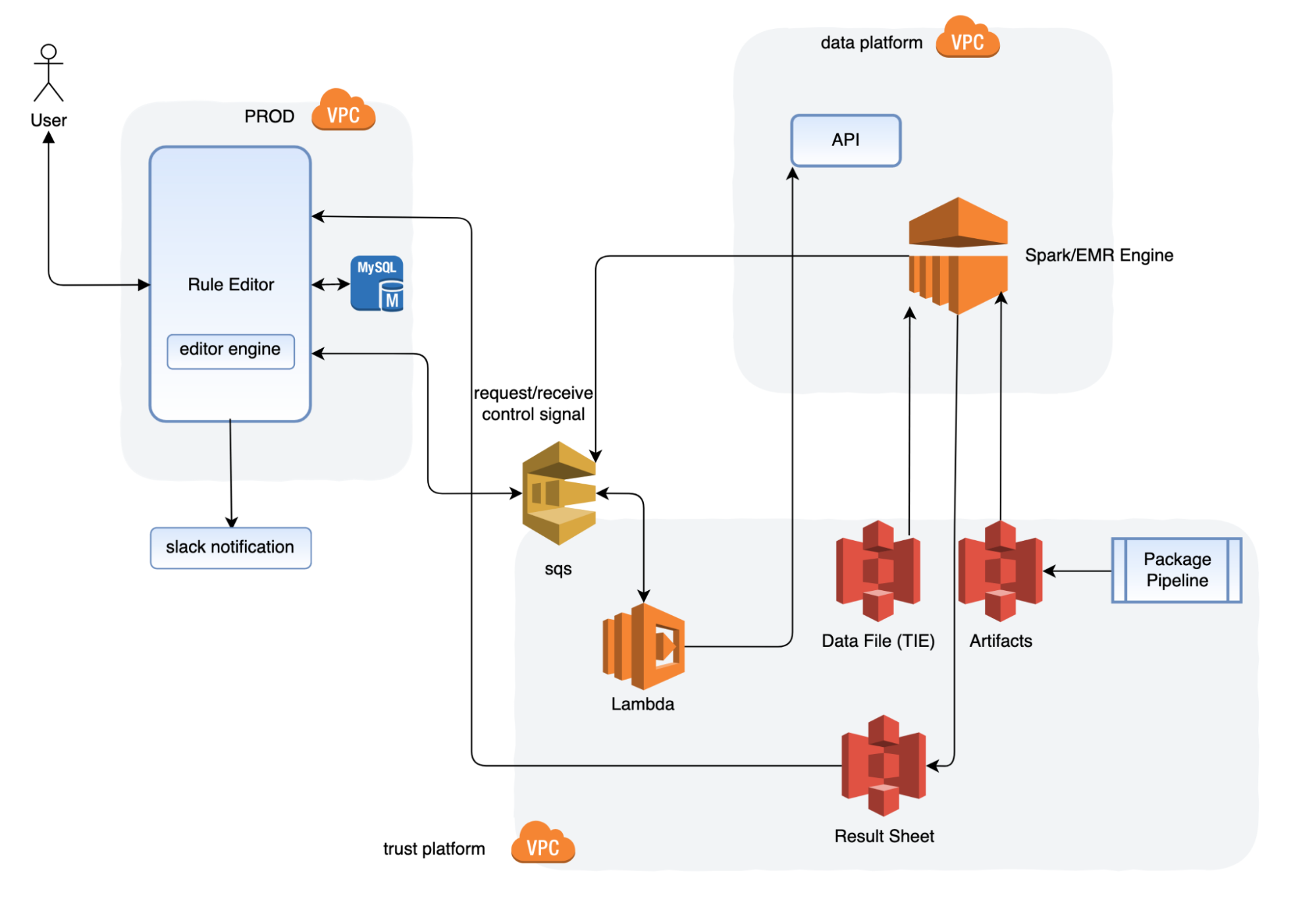
The rule editor UI reacts to the user input. Its engine sends a job command to the Amazon Simple Queue Service (SQS) to initialise the job. After that, the rule editor also performs the following processes in the background:
- Lambda listens to the request SQS queue and invokes a job via the Spark jobs API.
- The job fetches the executable artifacts, data source. After the job is completed, the job script saves the result sheet as required to S3.
- The Spark script pushes the job final status (success, failure, timeout) through the shutdown hook to respond to the SQS queue.
- The rule editor engine listens to response callback messages, and processes the job metadata to the database, or sends notifications.
- The rule editor displays the job metadata on the UI.
- The package pipeline builds and deploys the executable artifacts to S3 as a manageable structure.
- The Spark script takes the filter logic as its input parameters.
Workflow
Historical data preparation
The historical events are published by the rule engine through Kafka, and stored into the S3 bucket based on time. The Backtesting system then fetches these data for testing based on the time range requested.
By using a Kubernetes stream pipeline, we also save the trust inference stream to Trust AWS subaccount. With the customer bucket and file format, we can improve the efficiency of the data processing, and also avoid any delay from the data lake.
Engineering specifications
- Target location:
    s3a://stg-trust-inference-event/<engine-name>/<predict-name>/<YYYY>/MM/DD/hh/mm/ss/<000001>.snappy.parquet
    s3a://prd-trust-inference-event/<engine-name>/<predict-name>/<YYYY>/MM/DD/hh/mm/ss/<000001>.snappy.parquet
Description: Following the fields of steam definition, the engine name would be ruleengine, or catwalk. The predict-name would be preride (checkpoint name), or cnpu (model name).
- File Format: avro
- File Compression: Snappy
- There is no auto retention on sub-account S3. We will implement the archive process in the future.
- The default pipeline and the new pipeline will run in parallel until the Data Engineering team is ready to retire the default pipeline.
Backtesting
- Upon scheduling, the Backtesting Portal sends a message to SQS, which is then captured by the listening Lambda.
- Lambda invokes a Spark job over the AWS elastic mapreduce engine (EMR).
- The EMR engine fetches the executable artifacts containing the rule script and historical data from S3, and starts a Spark job to apply the rule script over historical data. Depending on the size of data, the Spark cluster will scale automatically to ensure timely completion.
- Once completed, a report file is generated and available on Backtesting UI.
UI
Learnings and conclusions
After the release, here’s what our data analysers had to say:
- For trust analysts, testing a rule on historical data happens outside the rule engine UI and is not user-friendly, leading to analysts wasting significant time.
- For financial analysts, as analysts migrate to the rule engine UI, the existing solution will be deprecated with no other solution.
- An alternative to simulate a rule; we no longer need to run a rule in shadow mode because we can use historical data to determine the outcome. This new approach saves us weeks of effort on the rule onboarding process.
What’s next?
The underlying Spark jobs in this tool were developed by knowledgeable data engineers, which is a disadvantage because it requires a high level of expertise to modify the analytics. To mitigate this restriction, we are looking into using domain-specific language (DSL) to allow users to input desired attributes and dimensions, and provide the job release pipeline for self-serving jobs.
Thanks to Jia Long Loh for the support on the offline infrastructure engineering.
Join us
Grab is the leading superapp platform in Southeast Asia, providing everyday services that matter to consumers. More than just a ride-hailing and food delivery app, Grab offers a wide range of on-demand services in the region, including mobility, food, package and grocery delivery services, mobile payments, and financial services across 428 cities in eight countries.
Powered by technology and driven by heart, our mission is to drive Southeast Asia forward by creating economic empowerment for everyone. If this mission speaks to you, join our team today!
[$] LWN.net Weekly Edition for September 8, 2022
Post Syndicated from original https://lwn.net/Articles/906796/
The LWN.net Weekly Edition for September 8, 2022 is available.
GitHub Availability Report: August 2022
Post Syndicated from Jakub Oleksy original https://github.blog/2022-09-07-github-availability-report-august-2022/
In August, we experienced one incident resulting in significant impact and degraded state of availability to Codespaces. This report also sheds light into an incident that impacted Codespaces in July.
August 29 12:51 UTC (lasting 5 hours and 40 minutes)
Our alerting systems detected an incident that impacted most Codespaces customers. Due to the recency of this incident, we are still investigating the contributing factors and will provide a more detailed update on cause and remediation in the September Availability Report, which will publish the first Wednesday of October.
Follow up to July 27 22:29 UTC (lasting 7 hours and 55 minutes)
As mentioned in the July Availability Report, we are now providing a more detailed update on this incident following further investigation. During this incident, a subset of codespaces in the East US and West US regions using 2-core and 4-core machine types could not be created or restarted.
On July 27, 2022 at approximately 21:30 UTC we started experiencing a high rate of failures creating new virtual machines (VMs) for Codespaces in the East US and West US regions. The rate of codespace creations and starts on the 2-core and 4-core machine types exceeded the rate of successful VM creations needed to run, which eventually led to resource exhaustion of the underlying VMs. At 22:29 UTC, the pools for 2-core and 4-core VMs were drained and unable to keep up with demand, so we statused yellow. Impacted codespaces took longer than normal to start while waiting for an available VM, and many ended up timing out and failing.
Each codespace runs on an isolated VM for security. The Codespaces platform builds a host VM image on a regular cadence, and then all host VMs are instantiated from that base image. This incident started when our cloud provider began rolling out an update in the East US and West US regions that was incompatible with the way we built our host VM image. Troubleshooting the failures was difficult because our cloud provider was reporting that the VMs were being created successfully even though some critical processes that were required to be started during VM creation were not running.
We applied temporary mitigations, including scaling up our VM pools to absorb the high failure rate, as well as adjusting timeouts to accelerate failure for VMs that were unlikely to succeed. While these mitigations helped, the failure rate continued to increase as our cloud provider’s update rolled out more broadly. Our cloud provider recommended adjusting our image generalization process in a way that would work with the new update. Once we made the recommended change to our image build pipeline, VM creation success rates recovered and enabled the backlog of queued codespace creation and start requests to be fulfilled with VMs to run the codespaces.
Following this incident, we have audited our VM image building process to ensure it aligns with our cloud provider’s guidance to prevent similar issues going forward. In addition, we have improved our service logic and monitoring to be able to verify that all critical operations are executed during VM creation rather than only looking at the result reported by our cloud provider. We have also updated our alerting to detect VM creation failures earlier before there is any user impact. Together, these changes will prevent this class of issue from happening, detect other failure modes earlier, and enable us to quickly diagnose and mitigate other VM creation errors in the future.
In summary
We will continue to keep you updated on the progress and investments we’re making to ensure the reliability of our services. To receive real-time updates on status changes, please follow our status page. You can also learn more about what we’re working on on the GitHub Engineering Blog.
Implement a highly available key distribution center for Amazon EMR
Post Syndicated from Lorenzo Ripani original https://aws.amazon.com/blogs/big-data/implement-a-highly-available-key-distribution-center-for-amazon-emr/
High availability (HA) is the property of a system or service to operate continuously without failing for a designated period of time. Implementing HA properties over a system allows you to eliminate single points of failure that usually translate to service disruptions, which can then lead to a business loss or the inability to use a service.
The core idea behind fault tolerance and high availability is very straightforward in terms of definition. You usually use multiple machines to give you redundancy for a specific service. This guarantees that if a host goes down, other machines are able to take over the traffic. Although this might be easy to say, it’s difficult to obtain such a property, especially when working with distributed technologies.
When focusing on Hadoop technologies, the concept of availability multiplies in different layers depending on the frameworks we’re using. To achieve a fault-tolerant system, we need to consider the following layers:
- Data layer
- Processing layer
- Authentication layer
The first two layers are typically handled using native capabilities of the Hadoop framework (such as HDFS High Availability or ResourceManager High Availability) or with the help of features available in the specific framework used (for example, HBase table replication to achieve highly available reads).
The authentication layer is typically managed through the utilization of the Kerberos protocol. Although multiple implementations of Kerberos exist, Amazon EMR uses a free implementation of the Kerberos protocol, which is directly provided by the Massachusetts Institute of Technology (MIT), also referred to as MIT Kerberos.
When looking at the native setup for a key distribution center (KDC), we can see that the tool comes with a typical primary/secondary configuration, where you can configure a primary KDC with one or more additional replicas to provide some features of a highly available system.
However, this configuration doesn’t provide an automatic failover mechanism to elect a new primary KDC in the event of a system interruption. As a result, the failover has to be performed manually or by implementing an automated process, which can be complex to set up.
With AWS native services, we can improve the MIT KDC capabilities to increase the resilience to failures of our system.
Highly available MIT KDC
Amazon EMR provides different architecture options to enable Kerberos authentication, where each of them tries to solve a specific need or use case. Kerberos authentication can be enabled by defining an Amazon EMR security configuration, which is a set of information stored within Amazon EMR itself. This enables you to reuse this configuration across multiple clusters.
When creating an Amazon EMR security configuration, you’re asked to choose between a cluster-dedicated KDC or an external KDC, so it’s important to understand the benefits and limits of each solution.
When you enable the cluster-dedicated KDC, Amazon EMR configures and installs an MIT KDC on the EMR primary node of the cluster that you’re launching. In contrast, when you use an external KDC, the cluster launched relies on a KDC external to the cluster. In this case, the KDC can be a cluster-dedicated KDC of a different EMR cluster that you reference as an external KDC, or a KDC installed on an Amazon Elastic Compute Cloud (Amazon EC2) instance or a container that you own.
The cluster-dedicated KDC is an easy configuration option that delegates the installation and configuration of the KDC service to the cluster itself. This option doesn’t require significant knowledge of the Kerberos system and might be a good option for a test environment. Additionally, having a dedicated KDC in a cluster enables you to segregate the Kerberos realm, thereby providing a dedicated authentication system that can be used only to authenticate a specific team or department in your organization.
However, because the KDC is located on the EMR primary node, you have to consider that if you delete the cluster, the KDC will be deleted as well. Considering the case in which the KDC is shared with other EMR clusters (defined as external KDC in their security configuration), the authentication layer for those will be compromised and as a result all Kerberos enabled frameworks will break. This might be acceptable in test environments, but it’s not recommended for a production one.
Because the KDC lifetime isn’t always bound to a specific EMR cluster, it’s common to use an external KDC located on an EC2 instance or Docker container. This pattern comes with some benefits:
- You can persist end-user credentials in the Kerberos KDC rather than using an Active Directory (although you can also enable a cross-realm trust)
- You can enable communication across multiple EMR clusters, so that all the cluster principals join the same Kerberos realm, thereby enabling a common authentication system for all the clusters
- You can remove the dependency of the EMR primary node, because deleting it will result in an impairment for other systems to authenticate
- If you require a multi-master EMR cluster, then an external KDC is required
That being said, installing an MIT KDC on a single instance doesn’t address our HA requirements, which typically are crucial in a production environment. In the following section, we discuss how we can implement a highly available MIT KDC using AWS services to improve the resiliency of our authentication system.
Architecture overview
The architecture presented in the following diagrams describes a highly available setup across multiple Availability Zones for our MIT Kerberos KDC that uses AWS services. We propose two versions of the architecture: one based on an Amazon Elastic File System (Amazon EFS) file system, and another based on an Amazon FSx for NetApp ONTAP file system.
Both services can be mounted on EC2 instances and used as local paths. Although Amazon EFS is cheaper compared to Amazon FSx for NetApp ONTAP, the latter provides better performance thanks to the sub-millisecond operation latency it provides.
We performed multiple tests to benchmark the solutions involving the different file systems. The following graph shows the results with Amazon EMR 5.36, in which we measured the time in seconds taken by the cluster to be fully up and running when selecting Hadoop and Spark as frameworks.

Looking at the test results, we can see that the Amazon EFS file system is suitable to handle small clusters (fewer than 100 nodes), because the performance degradation introduced by the latency of lock operations on the NFS protocol increases the delay in launching clusters as we add more nodes in our cluster topology. For example, for clusters with 200 nodes, the delay introduced by the Amazon EFS file system is such that some instances can’t join the cluster in time. As a result, those instances are deleted and then replaced, making the entire cluster provisioning slower. This is the reason why we decided not to publish any metric for Amazon EFS for 200 cluster nodes on the preceding graph.
On the other side, Amazon FSx for NetApp ONTAP is able to better handle the increasing number of principals created during the cluster provisioning with reduced performance degradation compared to Amazon EFS.
Even with the solution involving Amazon FSx for NetApp ONTAP, for clusters with a higher number of instances it’s still possible to encounter the behavior described earlier for Amazon EFS. Therefore, for big cluster configurations, this solution should be carefully tested and evaluated.
Amazon EFS based solution
The following diagram illustrates the architecture of our Amazon EFS based solution.

The infrastructure relies on different components to improve the fault tolerance of the KDC. The architecture uses the following services:
- A Network Load Balancer configured to serve Kerberos service ports (port 88 for authentication and port 749 for admin tasks like principals creation and deletion). The purpose of this component is to balance requests across multiple KDC instances located in separate Availability Zones. In addition, it provides a redirection mechanism in case of failures while connecting to an impaired KDC instance.
- An EC2 Auto Scaling group that helps you maintain KDC availability and allows you to automatically add or remove EC2 instances according to conditions you define. For the purpose of this scenario, we define a minimum number of KDC instances equal to two.
- The Amazon EFS file system provides a persistent and reliable storage layer for our KDC database. The service comes with built-in HA properties, so we can take advantage of its native features to obtain a persistent and reliable file system.
- We use AWS Secrets Manager to store and retrieve Kerberos configurations, in specific the password used for the Kadmin service, the Kerberos domain and realm managed by the KDC. With Secrets Manager, we avoid inputting any sensitive information as script parameters or passwords while launching KDC instances.
With this configuration, we eliminate the downsides resulting from a single instance installation:
- The KDC isn’t a single point of failure anymore because failed connections are redirected to healthy KDC hosts
- The lack of Kerberos traffic against the EMR primary node for the authentication will improve the health of our primary node, which might be critical for large Hadoop installations (hundreds of nodes)
- We can recover in case of failures, allowing survived instances to fulfill both admin and authentication operations
Amazon FSx for NetApp ONTAP based solution
The following diagram illustrates the solution using Amazon FSx for NetApp ONTAP.
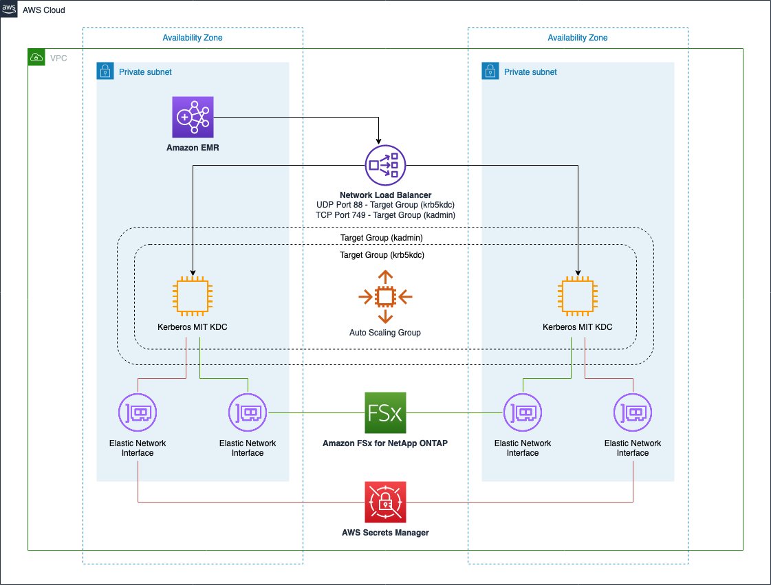
This infrastructure is almost identical compared to the previous one and provides the same benefits. The only difference is the utilization of a Multi-AZ Amazon FSx for NetApp ONTAP file system as a persistent and reliable storage layer for our KDC database. Even in this case, the service comes with built-in HA properties so we can take advantage of its native features to obtain a persistent and reliable file system.
Solution resources
We provide an AWS CloudFormation template in this post as a general guide. You should review and customize it as needed. You should also be aware that some of the resources deployed by this stack incur costs when they remain in use.
The CloudFormation template contains several nested templates. Together, they create the following:
- An Amazon VPC with two public and two private subnets where the KDC instances can be deployed
- An internet gateway attached to the public subnets and a NAT gateway for the private subnets
- An Amazon Simple Storage Service (Amazon S3) gateway endpoint and a Secrets Manager interface endpoint in each subnet
After the VPC resources are deployed, the KDC nested template is launched and provisions the following components:
- Two target groups, each connected to a listener for the specific KDC port to monitor (88 for Kerberos authentication and 749 for Kerberos administration).
- One Network Load Balancer to balance requests across the KDC instances created in different Availability Zones.
- Depending on the chosen file system, an Amazon EFS or Amazon FSx for NetApp ONTAP file system is created across multiple Availability Zones.
- Configuration and auto scaling to provision the KDC instances. In specific, the KDC instances are configured to mount the selected file system on a local folder that is used to store the principals database of the KDC.
At the end of the second template, the EMR cluster is launched with an external KDC set up and, if chosen, a multi-master configuration.
Launch the CloudFormation stack
To launch your stack and provision your resources, complete the following steps:
- Choose Launch Stack:

This automatically launches AWS CloudFormation in your AWS account with a template. It prompts you to sign in as needed. You can view the template on the AWS CloudFormation console as required. Make sure that you create the stack in your intended Region. The CloudFormation stack requires a few parameters, as shown in the following screenshot.


The following tables describe the parameters required in each section of the stack. - In the Core section, provide the following parameters:
Parameter Value (Default) Description Project aws-external-kdcThe name of the project for which the environment is deployed. This is used to create AWS tags associated to each resource created in the stack. Artifacts Repository aws-blogs-artifacts-public/artifacts/BDB-1689The Amazon S3 location hosting templates and script required to launch this stack. - In the Networking section, provide the following parameters:
Parameter Value (Default) Description VPC Network 10.0.0.0/16 Network range for the VPC (for example, 10.0.0.0/16). Public Subnet One 10.0.10.0/24 Network range for the first public subnet (for example, 10.0.10.0/24). Public Subnet Two 10.0.11.0/24 Network range for the second public subnet (for example, 10.0.11.0/24). Private Subnet One 10.0.1.0/24 Network range for the private subnet (for example, 10.0.1.0/24). Private Subnet Two 10.0.2.0/24 Network range for the private subnet (for example, 10.0.2.0/24). Availability Zone One (user selected) The Availability Zone chosen to host the first private and public subnets. This should differ from the value used for the Availability Zone Two parameter. Availability Zone Two (user selected) The Availability Zone chosen to host the second private and public subnets. This should differ from the value used for the Availability Zone One parameter. - In the KDC section, provide the following parameters:
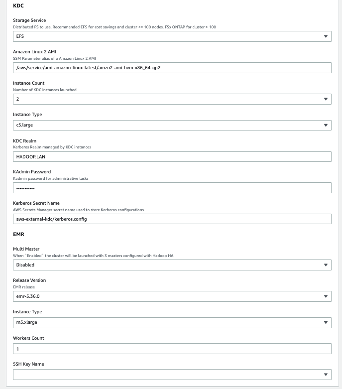
Parameter Value (Default) Description Storage Service Amazon EFS Specify the KDC shared file system: Amazon EFS or Amazon FSx for NetApp ONTAP. Amazon Linux 2 AMI /aws/service/ami-amazon-linux-latest/amzn2-ami-hvm-x86_64-gp2AWS Systems Manager parameter alias to retrieve the latest Amazon Linux 2 AMI. Instance Count 2Number of KDC instances launched. Instance Type c5.largeKDC instance type. KDC Realm HADOOP.LANThe Kerberos realm managed by the external KDC servers. KAdmin Password Password123The password to perform admin operations on the KDC. Kerberos Secret Name aws-external-kdc/kerberos.configSecrets Manager secret name used to store Kerberos configurations. - In the EMR section, provide the following parameters:
Parameter Value (Default) Description Multi Master Disabled When enabled, the cluster is launched with three primaries configured with Hadoop HA. Release Version emr-5.36.0 Amazon EMR release version. (Workers) Instance Type m5.xlarge The EC2 instance type used to provision the cluster. (Workers) Node Count 1 The number of Amazon EMR CORE nodes provisioned while launching the cluster. SSH Key Name (user selected) A valid SSH PEM key that will be attached to the cluster and KDC instances to provide SSH remote access. - Choose Next.
- Add additional AWS tags if required (the solution already uses some predefined AWS tags).
- Choose Next.
- Acknowledge the final requirements.
- Choose Create stack.

Make sure to select different Availability Zones in the Network selection of the template (Availability Zone One and Availability Zone Two). This prevents failures in the event of an impairment for an entire Availability Zone.
Test the infrastructure
After you’ve provisioned the whole infrastructure, it’s time to test and validate our HA setup.
In this test, we simulate an impairment on a KDC instance. As a result, we’ll see how we’re able to keep using remaining healthy KDCs, and we’ll see how the infrastructure self-recovers by adding an additional KDC as a substitution for the failed one.
We performed our tests by launching the CloudFormation stack and specifying two KDC instances and using Amazon EFS as the storage layer for the KDC database. The EMR cluster is launched with 11 CORE nodes.
After we deploy the whole infrastructure, we can connect to the EMR primary node using an SSH connection to perform our tests.

When inside our primary node instance, we can proceed with our test setup.
- First, we create 10 principals inside the KDC database. To do so, create a bash script named create_users.sh with the following content:
- Run the script using the following command:
- We can now verify those 10 principals have been correctly created inside the KDC database. To do so, create another script called
list_users.shand run it as the previous one:The output of the script shows the principals created by the cluster nodes when they’re provisioned, along with our test users just created.
We now run in parallel multiple
kinitrequests and while doing so, we stop thekrb5kdcprocess on one of the two available KDC instances.The test is performed through Spark to achieve high parallelization on the
kinitrequests. - First, create the following script and call it
user_kinit.sh: - Open a
spark-shelland use the--filesparameter to distribute the preceding bash script to all the Spark executors. In addition, we disable the Spark dynamic allocation and launch our application with 10 executors, each using 4 vCores. - We can now run the following Scala statements to initiate our distributed test:
This Spark application creates 1,600 tasks, and each task performs 10
kinitrequests. These tasks are run in parallel in batches of 40 Spark tasks at a time. The final output of our command returns the number of failedkinitrequests.

- We should now connect on the two available KDCs instances. We can connect without SSH keys by using AWS Systems Manager Session Manager because our template doesn’t provide any SSH key to the KDC instances for additional security. To connect on the KDC instances from the Amazon EC2 console using AWS Systems Manager, see Starting a session (Amazon EC2 console).
- On the first KDC, run the following commands to show incoming kinit authentication requests:
The following screenshot shows a sample output.

- On the second KDC, simulate a failure by running the following commands:
- We can now connect to the Amazon EC2 console and open the KDC related target group to confirm that the instance became unhealthy (after the three consecutive health checks failed), and was then deleted and replaced by a new one.
The target group performed the following specific steps during an impairment in one of the services:- The KDC instance enters the unhealthy state
- The unhealthy KDC instance is de-registered from the target group (draining process)
- A new KDC instance is launched
- The new KDC is registered to the target group so that it can start receiving traffic from the load balancer
You might expect to see output similar to the following screenshot while causing an impairment in one of your KDCs.

- If we now connect on the replaced KDC instance, we can see the traffic starting to appear in the
krbr5kdclogs.


At the end of the tests, we have a total number of failed Kerberos authentications.
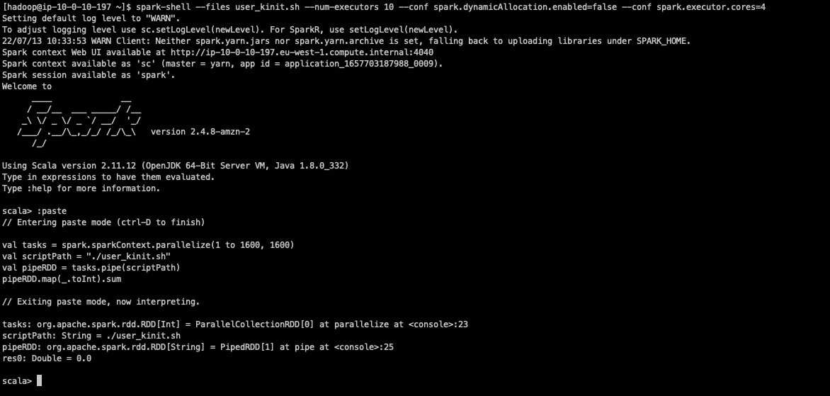
As we can see from the output result, we didn’t get any failure during this test. However, when repeating the test multiple times, you might still expect to see few errors (one or two on average) that might occur due to the krbr5kdc process stopping while some requests are still authenticating.
Note the kinit tool itself doesn’t have any retry mechanism. Both the Hadoop services running on the cluster and the creation of Kerberos principals during EMR instance provisioning are configured to retry if KDC calls fails.
If you want to automate these tests, you might also consider using AWS Fault Injection Simulator, a fully managed service for running fault injection experiments on AWS that makes it easier to improve an application’s performance, observability, and resiliency.
Clean up
To clean up all the resources:
- Delete the root stack in AWS CloudFormation.
- After a while from the deletion startup, you should see a failure.
- Click on the VPC nested CloudFormation stack, choose Resources.You should see a single
DELETE_FAILEDentry for the VPC resource. This is due to EMR automatically creating the Default Security Groups and those are preventing the VPC to be deleted by CloudFormation. - Move to the VPC section of the AWS console and delete that VPC manually.
- After that, move back to Cloudformation, select again the root stack and choose Delete. This time the deletion should complete.
File system backups
Both Amazon EFS and Amazon FSx for NetApp ONTAP are natively integrated with AWS Backup.
AWS Backup helps you automate and centrally manage your backups. After you create policy-driven plans, you can monitor the status of ongoing backups, verify compliance, and find and restore backups, all from a central console.
To get more information, refer to Using AWS Backup to back up and restore Amazon EFS file systems and Using AWS Backup with Amazon FSx.
Additional considerations
In this section, we share some additional considerations when using this solution.
Shared file system latency impacts
The utilization of a shared file system implies a degradation of the performance. In particular, the more Kerberos principals that have to be created at the same time, the more we can see a latency on the overall principals creation process and also on the cluster startup time.
This performance degradation is proportional to the number of parallel KDC requests made at the same time. For example, consider the scenario in which we have to launch 10 clusters, each with 20 nodes connected to the same KDC. If we launch all 10 clusters at the same time, we can potentially have 10×20 = 200 parallel connections to the KDC during the initial instance provisioning for the creation of the frameworks related Kerberos principals. In addition, because the duration of Kerberos tickets for services is 10 hours by default, and because all the cluster services are launched more or less at the same time, we could also have the same level of parallelism for service tickets renewal. If, instead, we launch these 10 clusters with a time gap between them, we’ll have potentially 20 parallel connections and as a result the latency introduced by the shared file system isn’t very impactful.
As discussed earlier in this post, multiple clusters can share the same KDC in case they need to communicate between each other without having to set up a cross-realm trust between the related KDCs. Before attaching multiple clusters to the same KDC, you should evaluate if there is a real need for that, because you might also consider segregating Kerberos realms on different KDC instances to obtain better performance and reduce the blast radius in case of issues.
Single-AZ high availability consideration
Although the solutions presented in this post might serve the purpose to provide a highly available MIT KDC across multiple Availability Zones, you might be only interested in providing an HA setup in a single Availability Zone. In this case, for better performance, you might also consider using Amazon FSx for Lustre, or attaching an IO2 EBS disk to multiple KDC instances in the same Availability Zone. In both cases, you might still use the same KDC script used in this post by just modifying the mount command to attach the shared file system on the KDC instances.
If you want to use an IO2 EBS volume as your shared file system, you have to set up a clustered file system to ensure data resiliency and reliability of our KDC database, because standard file systems such as XFS or EXT4 aren’t designed for such use cases. For example, you can use a GFS2 file system to access the KDC database simultaneously across KDC instances. For more details on how to set up a GFS2 file system on EC2 instances, refer to Clustered storage simplified: GFS2 on Amazon EBS Multi-Attach enabled volumes.
Summary
High availability and fault tolerance are key requirements for EMR clusters that can’t tolerate downtime. Analytics workloads run within those clusters can deal with sensitive data, therefore operating in a secured environment is also essential. As a result, we need a secure, highly available, and fault-tolerant setup.
In this post, we showed one possible way of achieving high availability and fault tolerance for the authentication layer of our big data workloads in Amazon EMR. We demonstrated how, by using AWS native services, multiple Kerberos KDCs can operate in parallel and be automatically replaced in case of failures. This, in combination with the framework-specific high availability and fault tolerance capabilities, allows us to operate in a secure, highly available, and fault-tolerant environment.
About the authors
 Lorenzo Ripani is a Big Data Solution Architect at AWS. He is passionate about distributed systems, open source technologies and security. He spends most of his time working with customers around the world to design, evaluate and optimize scalable and secure data pipelines with Amazon EMR.
 Stefano Sandona is an Analytics Specialist Solution Architect with AWS. He loves data, distributed systems and security. He helps customers around the world architecting their data platforms. He has a strong focus on Amazon EMR and all the security aspects around it.
Implement step-up authentication with Amazon Cognito, Part 2: Deploy and test the solution
Post Syndicated from Salman Moghal original https://aws.amazon.com/blogs/security/implement-step-up-authentication-with-amazon-cognito-part-2-deploy-and-test-the-solution/
This solution consists of two parts. In the previous blog post Implement step-up authentication with Amazon Cognito, Part 1: Solution overview, you learned about the architecture and design of a step-up authentication solution that uses AWS services such as Amazon API Gateway, Amazon Cognito, Amazon DynamoDB, and AWS Lambda to protect privileged API operations. In this post, you will use a reference implementation to deploy and test the step-up authentication solution in your AWS account.
Solution deployment
The step-up authentication solution discussed in Part 1 uses a reference implementation that you can use for demonstration and learning purposes. You can also review the implementation code in the step-up-auth GitHub repository. The reference implementation includes a web application that you can use in the following sections to test the step-up implementation. Additionally, the implementation contains a sample privileged API action /transfer and a non-privileged API action /info, and two step-up authentication solution API operations /initiate-auth, and /respond-to-challenge. The web application invokes these API operations to demonstrate how to perform step-up authentication.
Deployment prerequisites
The following are prerequisites for deployment:
- The Node.js runtime and the node package manager (npm) are installed on your machine. You can use a package manager for your platform to install these. Note that the reference implementation code was tested using Node.js v16 LTS.
- The AWS Cloud Development Kit (AWS CDK) is installed in your environment.
- The AWS Command Line Interface (AWS CLI) is installed in your environment.
- You must have AWS credentials files that contain a profile with your account secret key and access key to perform the deployment. Make sure that your account has enough privileges to create, update, or delete the following resources:
- Amazon Cognito
- Amazon API Gateway API and resources
- Amazon Simple Storage Service (Amazon S3) buckets
- Amazon CloudFront distributions
- Amazon DynamoDB tables
- AWS Lambda functions
- AWS Identity and Access Management (AWS IAM) roles
- A two-factor authentication (2FA) mobile application, such as Google Authenticator, is installed on your mobile device.
Deploy the step-up solution
You can deploy the solution by using the AWS CDK, which will create a working reference implementation of the step-up authentication solution.
To deploy the solution
- Build the necessary resources by using the build.sh script in the deployment folder. Run the build script from a terminal window, using the following command:
cd deployment && ./build.sh - Deploy the solution by using the deploy.sh script that is present in the deployment folder, using the following command. Be sure to replace the required environment variables with your own values.
export AWS_REGION=<your AWS Region of choice, for example us-east-2>
 export AWS_ACCOUNT=<your account number>
 export AWS_PROFILE=<a valid profile in .aws/credentials that contains the secret/access key to your account>
 export NODE_ENV=development
 export ENV_PREFIX=dev
The account you specify in the AWS_ACCOUNT environment variable is used to bootstrap the AWS CDK deployment. Set AWS_PROFILE to point to your profile. Make sure that your account has sufficient privileges, as described in the prerequisites.
The NODE_ENV environment variable can be set to development or production. This variable controls the log output that the Lambda functions generate. The ENV_PREFIX environment variable allows you to prefix all resources with a tag, which enables a multi-tenant deployment of this solution.
- Still in the deployment folder, deploy the stack by using the following command:
./deploy.sh - Make note of the CloudFront distribution URL that follows Sample Web App URL, as shown in Figure 1. In the next section, you will use this CloudFront distribution URL to load the sample web app in a web browser and test the step-up solution

Figure 1: The output of the deployment process

After the deployment script deploy.sh completes successfully, the AWS CDK creates the following resources in your account:
- An Amazon Cognito user pool that is used as a user registry.
- An Amazon API Gateway API that contains three resources:
- A protected resource that requires step-up authentication.
- An initiate-auth resource to start the step-up challenge response.
- A respond-to-challenge resource to complete the step-up challenge.
- An API Gateway Lambda authorizer that is used to protect API actions.
- The following Amazon DynamoDB tables:
- A setting table that holds the configuration mapping of the API operations that require elevated privileges.
- A session table that holds temporary, user-initiated step-up sessions and their current status.
- A React web UI that demonstrates how to invoke a privileged API action and go through step-up authentication.
Test the step-up solution
In order to test the step-up solution, you’ll use the sample web application that you deployed in the previous section. Here’s an overview of the actions you’ll perform to test the flow:
- In the AWS Management Console, create items in the setting DynamoDB table that point to privileged API actions. After the solution deployment, the setting DynamoDB table is called step-up-auth-setting-<ENV_PREFIX>. For more information about ENV_PREFIX variable usage in a multi-tenant environment, see Deploy the step-up solution earlier in this post.
As discussed, in the Data design section in Part 1 of this series, the Lambda authorizer treats all API invocations as non-privileged (that is, they don’t require step-up authentication) unless there is a matching entry for the API action in the setting table. Additionally, you can switch a privileged API action to a non-privileged API action by simply changing the stepUpState attribute in the setting table. Create an item in the DynamoDB table for the sample /transfer API action and for the sample /info API action. The /transfer API action will require step-up authentication, whereas the /info API action will be a non-privileged invocation that does not require step-up authentication. Note that there is no need to define a non-privileged API action in the table; it is there for illustration purposes only.
- If you haven’t already, install Google Authenticator or a similar two-factor authentication (2FA) application on your mobile device.
- Using the sample web application, register a new user in Amazon Cognito.
- Log in to the sample web application by using the registered new user.
- Configure the preferred multi-factor authentication (MFA) settings for the logged in user in the application. This step is necessary so that Amazon Cognito can challenge the user with a one-time password (OTP).
- Using the sample web application, invoke the sample /transfer privileged API action that requires step-up authentication.
- The Lambda authorizer will intercept the API request and return a 401 Unauthorized response status code that the sample web application will handle. The application will perform step-up authentication by prompting you to provide additional security credentials, specifically the OTP. To complete the step-up authentication, enter the OTP, which is sent through short service message (SMS) or by using an authenticator mobile app.
- Invoke the sample /transfer privileged API action again in the sample web application, and verify that the API invocation is successful.
The following instructions assume that you’ve installed a 2FA mobile application, such as Google Authenticator, on your mobile device. You will configure the 2FA application in the following steps and use the OTP from this mobile application when prompted to enter the step-up challenge. You can configure Amazon Cognito to send you an SMS with the OTP. However, you must be aware of the Amazon Cognito throttling limits. See the Additional considerations section in Part 1 of this series. Read these limits carefully, especially if you set the user’s preferred MFA setting to SMS.
To test the step-up authentication solution
- Open the Amazon DynamoDB console and log in to your AWS account.
- On the left nav pane, under Tables, choose Explore items. In the right pane, choose the table named step-up-auth-setting* and choose Create item, as shown in Figure 2.
Figure 2: Choose the step-up-auth-setting* table and choose Create item button
- In the Edit item screen as shown in Figure 3, ensure that JSON is selected, and the Attributes button for View DynamoDB JSON is off.
Figure 3: Edit an item in the table – select JSON and turn off View DynamoDB JSON button
- To create an entry for the /info API action, copy the following JSON text:
{ "id": "/info", "lastUpdateTimestamp": "2021-08-23T08:25:29.023Z", "stepUpState": "STEP_UP_NOT_REQUIRED", "createTimestamp": "2021-08-23T08:25:29.023Z" } - Paste the copied JSON text for the /info API action in the Attributes text area, as shown in Figure 4, and choose Create item.
Figure 4: Create an entry for the /info API action
- To create an entry for the /transfer API action, copy the following JSON text:
{ "id": "/transfer", "lastUpdateTimestamp": "2021-08-23T08:22:12.436Z", "stepUpState": "STEP_UP_REQUIRED", "createTimestamp": "2021-08-23T08:22:12.436Z" } - Paste the copied JSON text for the /transfer API action in the Attributes text area, as shown in Figure 4, and choose Create item.
Figure 5: Create an entry for the /transfer API action
- Open your web browser and load the CloudFront URL that you made note of in step 4 of the Deploy the step-up solution procedure.
- On the login screen of the sample web application, enter the information for a new user. Make sure that the email address and phone numbers are valid. Choose Register. You will be prompted to enter a verification code. Check your email for the verification code, and enter it at the sample web application prompt.
- You will be sent back to the login screen. Log in as the user that you just registered. You will see the welcome screen, as shown in Figure 6.
Figure 6: Welcome screen of the sample web application
- In the left nav pane choose Setting, choose the Configure button to the right of Software Token, as shown in Figure 7. Use your mobile device camera to capture the QR code on the screen in your 2FA application, for example Google Authenticator.
Figure 7: Configure Software Token screen with QR code
- Enter the temporary code from the 2FA application into the web application and choose Submit. You will see the message Software Token successfully configured!
- Still in the Setting menu, next to Select Preferred MFA, choose Software Token. You will see the message User preferred MFA set to Software Token, as shown in Figure 8.
Figure 8: Completed Software Token setup
- In the left nav pane choose StepUp Auth. In the right pane, choose Invoke Transfer API. You should see Response: 401 authorization challenge, as shown in Figure 9.
Figure 9: The step-up API invocation returns an authorization challenge
- On your mobile device, open the 2FA application, copy the OTP code from the 2FA application, and enter the code into the Enter OTP field, as shown in Figure 9. Choose Submit.
- This sends the OTP to the respond-to-challenge endpoint. After the OTP is verified, the endpoint will return a success or failure message. Figure 10 shows a successful OTP verification. You are prompted to invoke the /transfer privileged API action again.
Figure 10: The OTP prompt during step-up API invocation
- Invoke the transfer API action again by choosing Invoke Transfer API. You should see a success message as shown in Figure 11.
Figure 11: A successful step-up API invocation
Congratulations! You’ve successfully performed step-up authentication.


Conclusion
In the previous post in this series, Implement step-up authentication with Amazon Cognito, Part 1: Solution overview, you learned about the architecture and implementation details for the step-up authentication solution. In this blog post, you learned how to deploy and test the step-up authentication solution in your AWS account. You deployed the solution by using scripts from the step-up-auth GitHub repository that use the AWS CDK to create resources in your account for Amazon Cognito, Amazon API Gateway, a Lambda authorizer, and Amazon DynamoDB. Finally, you tested the end-to-end solution on a sample web application by invoking a privileged API action that required step-up authentication. Using the 2FA application, you were able to pass in an OTP to complete the step-up authentication and subsequently successfully invoke the privileged API action.
For more information about AWS Cognito user pools and the new console experience, watch the video Amazon Cognito User Pools New Console Walkthrough on the AWS channel on YouTube. And for more information about how to protect your API actions with fine-grained access controls, see the blog post Building fine-grained authorization using Amazon Cognito, API Gateway, and IAM.
If you have feedback about this post, submit comments in the Comments section below. If you have any questions about this post, start a thread on the Amazon Cognito forum.
Want more AWS Security news? Follow us on Twitter.
Create single output files for recipe jobs using AWS Glue DataBrew
Post Syndicated from Dhiraj Thakur original https://aws.amazon.com/blogs/big-data/create-single-output-files-for-recipe-jobs-using-aws-glue-databrew/
AWS Glue DataBrew offers over 350 pre-built transformations to automate data preparation tasks (such as filtering anomalies, standardizing formats, and correcting invalid values) that would otherwise require days or weeks writing hand-coded transformations.
You can now choose single or multiple output files instead of autogenerated files for your DataBrew recipe jobs. You can generate a single output file when the output is small or downstream systems need to consume it more easily, such as visualization tools. Alternatively, you can specify your desired number of output files when configuring a recipe job. This gives you the flexibility to manage recipe job output for visualization, data analysis, and reporting, while helping prevent you from generating too many files. In some cases, you may also want to customize the output file partitions for efficient storage and transfer.
In this post, we walk you through how to connect and transform data from an Amazon Simple Storage Service (Amazon S3) data lake and configure the output as a single file via the DataBrew console.
Solution overview
The following diagram illustrates our solution architecture.

DataBrew queries sales order data from the S3 data lake and performs data transformation. Then the DataBrew job writes the final output back to the data lake in a single file.
To implement the solution, you complete the following high-level steps:
- Create a dataset.
- Create a DataBrew project using the dataset.
- Build a transformation recipe.
- Create and run a DataBrew recipe job on the full data.
Prerequisites
To complete this solution, you should have an AWS account and the appropriate permissions to create the resources required as part of the solution.
You also need a dataset in Amazon S3. For our use case, we use a mock dataset. You can download the data files from GitHub. On the Amazon S3 console, upload all three CSV files to an S3 bucket.
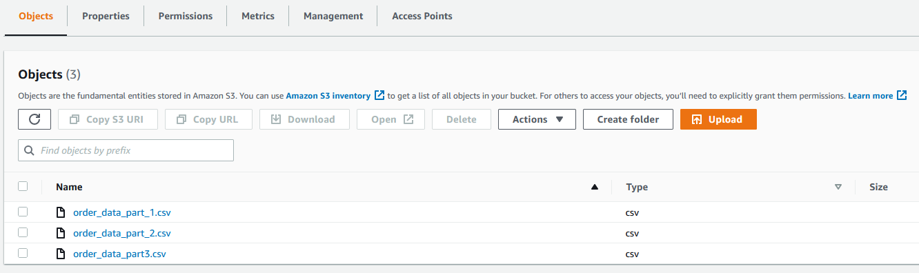
Create a dataset
To create your dataset in DataBrew, complete the following steps:
- On the Datasets page of the DataBrew console, choose Connect new dataset.

- For Dataset name, enter a name (for example,
order). - Enter the S3 bucket path where you uploaded the data files as part of the prerequisite steps.
- Choose Select the entire folder.

- For File type¸ select CSV and choose Comma (,) for CSV delimiter.
- For Column header values, select Treat first row as header.
- Choose Create dataset.


Create a DataBrew project using the dataset
To create your DataBrew project, complete the following steps:
- On the DataBrew console, on the Projects page, choose Create project.

- For Project Name, enter
valid-order. - For Attached recipe, choose Create new recipe.
The recipe name is populated automatically (valid-order-recipe).

- For Select a dataset, select My datasets.
- Select the
orderdataset.

- For Role name, choose the AWS Identity and Access Management (IAM) role to be used with DataBrew.
- Choose Create project.


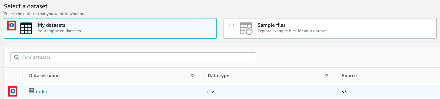
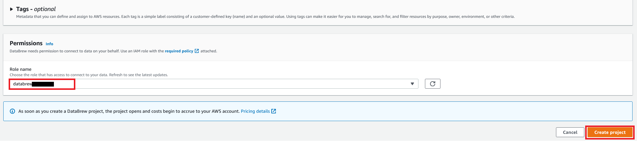
You can see a success message along with our Amazon S3 order table with 500 rows.
After the project is opened, a DataBrew interactive session is created. DataBrew retrieves sample data based on your sampling configuration selection.
Build a transformation recipe
In a DataBrew interactive session, you can cleanse and normalize your data using over 350 pre-built transformations. In this post, we use DataBrew to perform a few transforms and filter only valid orders with order amounts greater than $0.
To do this, you perform the following steps:
- Choose Column and choose Delete.

- For Source columns, choose the columns
order_id, timestamp, andtransaction_date. - Choose Apply.

- We filter the rows based on an
amountvalue greater than $0 and add the condition as a recipe step.

- To create a custom sort based on state, choose SORT and choose Ascending.

- For Source, choose the column
state_name. - Select Sort by custom values.
- Enter a list of state names separated by commas.
- Choose Apply.


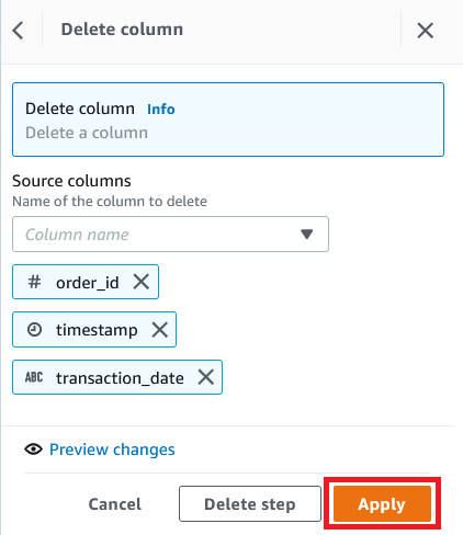


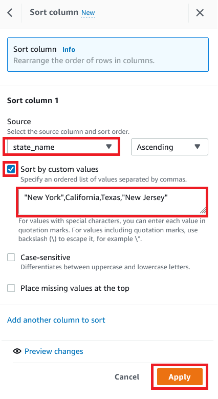
The following screenshot shows the full recipe that we applied to our dataset.

Create and run a DataBrew recipe job on the full data
Now that we have built the recipe, we can create and run a DataBrew recipe job.
- On the project details page, choose Create job.
- For Job name, enter
valid-order.

- For Output to, choose Amazon S3.
- Enter the S3 path to store the output file.
- Choose Settings.


For File output options, you have multiple options:
-
- Autogenerate files – This is the default file output setting, which generates multiple files and usually results in the fastest job runtime
- Single file output – This option generates a single output file
- Multiple file output – With this option, you specify the maximum number of files you want to split your data into
- For this post, select Single file output.
- Choose Save.

- For Role name, choose the IAM role to be used with DataBrew.
- Choose Create and run job.

- Navigate to the Jobs page and wait for the
product-wise-sales-jobjob to complete.

- Navigate to output S3 bucket to confirm that a single output file is stored there.


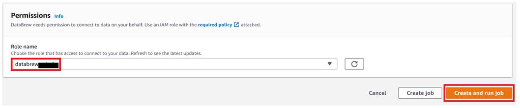

Clean up
To avoid incurring future charges, delete all the resources created during this walkthrough:
- Delete the recipe job
valid-order. - Empty the job output stored in your S3 bucket and delete the bucket.
- Delete the IAM roles created as part of your projects and jobs.
- Delete the project
valid-orderand its associated recipevalid-order-recipe. - Delete the DataBrew datasets.
Conclusion
In this post, we showed how to connect and transform data from an S3 data lake and create a DataBrew dataset. We also demonstrated how we can bring data from our data lake into DataBrew, seamlessly apply transformations, and write the prepared data back to the data lake in a single output file.
To learn more, refer to Creating and working with AWS Glue DataBrew recipe jobs.
About the Author
 Dhiraj Thakur is a Solutions Architect with Amazon Web Services. He works with AWS customers and partners to provide guidance on enterprise cloud adoption, migration, and strategy. He is passionate about technology and enjoys building and experimenting in the analytics and AI/ML space.
Implement step-up authentication with Amazon Cognito, Part 1: Solution overview
Post Syndicated from Salman Moghal original https://aws.amazon.com/blogs/security/implement-step-up-authentication-with-amazon-cognito-part-1-solution-overview/
In this blog post, you’ll learn how to protect privileged business transactions that are exposed as APIs by using multi-factor authentication (MFA) or security challenges. These challenges have two components: what you know (such as passwords), and what you have (such as a one-time password token). By using these multi-factor security controls, you can implement step-up authentication to obtain a higher level of security when you perform critical transactions. In this post, we show you how you can use AWS services such as Amazon API Gateway, Amazon Cognito, Amazon DynamoDB, and AWS Lambda functions to implement step-up authentication by using a simple rule-based security model for your API resources.
Previously, identity and access management solutions have attempted to deliver step-up authentication by retrofitting their runtimes with stateful server-side management, which doesn’t scale in the modern-day stateless cloud-centered application architecture. We’ll show you how to use a pluggable, stateless authentication implementation that integrates into your existing infrastructure without compromising your security or performance. The Amazon API Gateway Lambda authorizer is a pluggable serverless function that acts as an intermediary step before an API action is invoked. This Lambda authorizer, coupled with a small SDK library that runs in the authorizer, will provide step-up authentication.
This solution consists of two blog posts. This is Part 1, where you’ll learn about the step-up authentication solution architecture and design. In the next post, Implement step-up authentication with Amazon Cognito, Part 2: Deploy and test the solution, you’ll learn how to use a reference implementation to test the step-up authentication solution.
Prerequisites
The reference architecture in this post uses a purpose-built step-up authorization workflow engine, which uses a custom SDK. The custom SDK uses the DynamoDB service as a persistent layer. This workflow engine is generic and can be used across any API serving layers, such as API Gateway or Elastic Load Balancing (ELB) Application Load Balancer, as long as the API serving layers can intercept API requests to perform additional actions. The step-up workflow engine also relies on an identity provider that is capable of issuing an OAuth 2.0 access token.
There are three parts to the step-up authentication solution:
- An API serving layer with the capability to apply custom logic before applying business logic.
- An OAuth 2.0–capable identity provider system.
- A purpose-built step-up workflow engine.
The solution in this post uses Amazon Cognito as the identity provider, with an API Gateway Lambda authorizer to invoke the step-up workflow engine, and DynamoDB as a persistent layer used by the step-up workflow engine. You can see a reference implementation of the API Gateway Lambda authorizer in the step-up-auth GitHub repository. Additionally, the purpose-built step-up workflow engine provides two API endpoints (or API actions), /initiate-auth and /respond-to-challenge, which are realized using the API Gateway Lambda authorizer, to drive the API invocation step-up state.
Note: If you decide to use an API serving layer other than API Gateway, or use an OAuth 2.0 identity provider besides Amazon Cognito, you will have to make changes to the accompanying sample code in the step-up-auth GitHub repository.
Solution architecture
Figure 1 shows the high-level reference architecture.

Figure 1: Step-up authentication high-level reference architecture
First, let’s talk about the core components in the step-up authentication reference architecture in Figure 1.
Identity provider
In order for a client application or user to invoke a protected backend API action, they must first obtain a valid OAuth token or JSON web token (JWT) from an identity provider. The step-up authentication solution uses Amazon Cognito as the identity provider. The step-up authentication solution and the accompanying step-up API operations use the access token to make the step-up authorization decision.
Protected backend
The step-up authentication solution uses API Gateway to protect backend resources. API Gateway supports several different API integration types, and you can use any one of the supported API Gateway integration types. For this solution, the accompanying sample code in the step-up-auth GitHub repository uses Lambda proxy integration to simulate a protected backend resource.
Data design
The step-up authentication solution relies on two DynamoDB tables, a session table and a setting table. The session table contains the user’s step-up session information, and the setting table contains an API step-up configuration. The API Gateway Lambda authorizer (described in the next section) checks the setting table to determine whether the API request requires a step-up session. For more information about table structure and sample values, see the Step-up authentication data design section in the accompanying GitHub repository.
The session table has the DynamoDB Time to Live (TTL) feature enabled. An item stays in the session table until the TTL time expires, when DynamoDB automatically deletes the item. The TTL value can be controlled by using the environment variable SESSION_TABLE_ITEM_TTL. Later in this post, we’ll cover where to define this environment variable in the Step-up solution design details section; and we’ll cover how to set the optimal value for this environment variable in the Additional considerations section.
Authorizer
The step-up authentication solution uses a purpose-built request parameter-based Lambda authorizer (also called a REQUEST authorizer). This REQUEST authorizer helps protect privileged API operations that require a step-up session.
The authorizer verifies that the API request contains a valid access token in the HTTP Authorization header. Using the access token’s JSON web token ID (JTI) claim as a key, the authorizer then attempts to retrieve a step-up session from the session table. If a session exists and its state is set to either STEP_UP_COMPLETED or STEP_UP_NOT_REQUIRED, then the authorizer lets the API call through by generating an allow API Gateway Lambda authorizer policy. If the set-up state is set to STEP_UP_REQUIRED, then the authorizer returns a 401 Unauthorized response status code to the caller.
If a step-up session does not exist in the session table for the incoming API request, then the authorizer attempts to create a session. It first looks up the setting table for the API configuration. If an API configuration is found and the configuration status is set to STEP_UP_REQUIRED, it indicates that the user must provide additional authentication in order to call this API action. In this case, the authorizer will create a new session in the session table by using the access token’s JTI claim as a session key, and it will return a 401 Unauthorized response status code to the caller. If the API configuration in the setting table is set to STEP_UP_DENY, then the authorizer will return a deny API Gateway Lambda authorizer policy, therefore blocking the API invocation. The caller will receive a 403 Forbidden response status code.
The authorizer uses the purpose-built auth-sdk library to interface with both the session and setting DynamoDB tables. The auth-sdk library provides convenient methods to create, update, or delete items in tables. Internally, auth-sdk uses the DynamoDB v3 Client SDK.
Initiate auth endpoint
When you deploy the step-up authentication solution, you will get the following two API endpoints:
- The initiate step-up authentication endpoint (described in this section).
- The respond to step-up authentication challenge endpoint (described in the next section).
When a client receives a 401 Unauthorized response status code from API Gateway after invoking a privileged API operation, the client can start the step-up authentication flow by invoking the initiate step-up authentication endpoint (/initiate-auth).
The /initiate-auth endpoint does not require any extra parameters, it only requires the Amazon Cognito access_token to be passed in the Authorization header of the request. The /initiate-auth endpoint uses the access token to call the Amazon Cognito API actions GetUser and GetUserAttributeVerificationCode on behalf of the user.
After the /initiate-auth endpoint has determined the proper multi-factor authentication (MFA) method to use, it returns the MFA method to the client. There are three possible values for the MFA methods:
- MAYBE_SOFTWARE_TOKEN_STEP_UP, which is used when the MFA method cannot be determined.
- SOFTWARE_TOKEN_STEP_UP, which is used when the user prefers software token MFA.
- SMS_STEP_UP, which is used when the user prefers short message service (SMS) MFA.
Let’s take a closer look at how /initiate-auth endpoint determines the type of MFA methods to return to the client. The endpoint calls Amazon Cognito GetUser API action to check for user preferences, and it takes the following actions:
- Determines what method of MFA the user prefers, either software token or SMS.
- If the user’s preferred method is set to software token, the endpoint returns SOFTWARE_TOKEN_STEP_UP code to the client.
- If the user’s preferred method is set to SMS, the endpoint sends an SMS message with a code to the user’s mobile device. It uses the Amazon Cognito GetUserAttributeVerificationCode API action to send the SMS message. After the Amazon Cognito API action returns success, the endpoint returns SMS_STEP_UP code to the client.
- When the user preferences don’t include either a software token or SMS, the endpoint checks if the response from Amazon Cognito GetUser API action contains UserMFASetting response attribute list with either SOFTWARE_TOKEN_MFA or SMS_MFA keywords. If the UserMFASetting response attribute list contains SOFTWARE_TOKEN_MFA, then the endpoint returns SOFTWARE_TOKEN_STEP_UP code to the client. If it contains SMS_MFA keyword, then the endpoint invokes the Amazon Cognito GetUserAttributeVerificationCode API action to send the SMS message (as in step 3). Upon successful response from the Amazon Cognito API action, the endpoint returns SMS_STEP_UP code to the client.
- If the UserMFASetting response attribute list from Amazon Cognito GetUser API action does not contain SOFTWARE_TOKEN_MFA or SMS_MFA keywords, then the endpoint looks for phone_number_verified attribute. If found, then the endpoint sends an SMS message with a code to the user’s mobile device with verified phone number. The endpoint uses the Amazon Cognito GetUserAttributeVerificationCode API action to send the SMS message (as in step 3). Otherwise, when no verified phone is found, the endpoint returns MAYBE_SOFTWARE_TOKEN_STEP_UP code to the client.
The flowchart shown in Figure 2 illustrates the full decision logic.

Figure 2: MFA decision flow chart
Respond to challenge endpoint
The respond to challenge endpoint (/respond-to-challenge) is called by the client after it receives an appropriate MFA method from the /initiate-auth endpoint. The user must respond to the challenge appropriately by invoking /respond-to-challenge with a code and an MFA method.
The /respond-to-challenge endpoint receives two parameters in the POST body, one indicating the MFA method and the other containing the challenge response. Additionally, this endpoint requires the Amazon Cognito access token to be passed in the Authorization header of the request.
If the MFA method is SMS_STEP_UP, the /respond-to-challenge endpoint invokes the Amazon Cognito API action VerifyUserAttribute to verify the user-provided challenge response, which is the code that was sent by using SMS.
If the MFA method is SOFTWARE_TOKEN_STEP_UP or MAYBE_SOFTWARE_TOKEN_STEP_UP, the /respond-to-challenge endpoint invokes the Amazon Cognito API action VerifySoftwareToken to verify the challenge response that was sent in the endpoint payload.
After the user-provided challenge response is verified, the /respond-to-challenge endpoint updates the session table with the step-up session state STEP_UP_COMPLETED by using the access_token JTI. If the challenge response verification step fails, no changes are made to the session table. As explained earlier in the Data design section, the step-up session stays in the session table until the TTL time expires, when DynamoDB will automatically delete the item.
Deploy and test the step-up authentication solution
If you want to test the step-up authentication solution at this point, go to the second part of this blog, Implement step-up authentication with Amazon Cognito, Part 2: Deploy and test the solution. That post provides instructions you can use to deploy the solution by using the AWS Cloud Development Kit (AWS CDK) in your AWS account, and test it by using a sample web application.
Otherwise, you can continue reading the rest of this post to review the details and code behind the step-up authentication solution.
Step-up solution design details
Now let’s dig deeper into the step-up authentication solution. Figure 3 expands on the high-level solution design in the previous section and highlights the sequence of events that must take place to perform step-up authentication. In this section, we’ll break down these sequences into smaller parts and discuss each by going over a detailed sequence diagram.

Figure 3: Step-up authentication detailed reference architecture
Let’s group the step-up authentication flow in Figure 3 into three parts:
- Create a step-up session (steps 1-6 in Figure 3)
- Initiate step-up authentication (steps 7-8 in Figure 3)
- Respond to the step-up challenge (steps 9-12 in Figure 3)
In the next sections, you’ll learn how the user’s API requests are handled by the step-up authentication solution, and how the user state is elevated by going through an additional challenge.
Create a step-up session
After the user successfully logs in, they create a step-up session when invoking a privileged API action that is protected with the step-up Lambda authorizer. This authorizer determines whether to start a step-up challenge based on the configuration within the DynamoDB setting table, which might create a step-up session in the DynamoDB session table. Let’s go over steps 1–6, shown in the architecture diagram in Figure 3, in more detail:
- Step 1 – It’s important to note that the user must authenticate with Amazon Cognito initially. As a result, they must have a valid access token generated by the Amazon Cognito user pool.
- Step 2 – The user then invokes a privileged API action and passes the access token in the Authorization header.
- Step 3 – The API action is protected by using a Lambda authorizer. The authorizer first validates the token by invoking the Amazon Cognito user pool public key. If the token is invalid, a 401 Unauthorized response status code can be sent immediately, prompting the client to present a valid token.
- Step 4 – The authorizer performs a lookup in the DynamoDB setting table to check whether the current request needs elevated privilege (also known as step-up privilege). In the setting table, you can define which API actions require elevated privilege. You can additionally bundle API operations into a group by defining the group attribute. This allows you to further isolate privileged API operations, especially in a large-scale deployment.
- Step 5 – If an API action requires elevated privilege, the authorizer will check for an existing step-up session for this specific user in the session table. If a step-up session does not exist, the authorizer will create a new entry in the session table. The key for this table will be the JTI claim of the access_token (which can be obtained after token verification).
- Step 6 – If a valid session exists, then authorization will be given. Otherwise an unauthorized access response (401 HTTP code) will be sent back from the Lambda authorizer, indicating that the user requires elevated privilege.
Figure 4 highlights these steps in a sequence diagram.

Figure 4: Sequence diagram for creating a step-up session
Initiate step-up authentication
After the user receives a 401 Unauthorized response status code from invoking the privileged API action in the previous step, the user must call the /initiate-auth endpoint to start step-up authentication. The endpoint will return the response to the user or the client application to supply the temporary code. Let’s go over steps 7 and 8, shown in the architecture diagram in Figure 3, in more detail:
- Step 7 – The client application initiates a step-up action by calling the /initiate-auth endpoint. This action is protected by the API Gateway built-in Amazon Cognito authorizer, and the client needs to pass a valid access_token in the Authorization header.
- Step 8 – The call is forwarded to a Lambda function that will initiate the step-up action with the end user. The function first calls the Amazon Cognito API action GetUser to find out the user’s MFA settings. Depending on which MFA type is enabled for the user, the function uses different Amazon Cognito API operations to start the MFA challenge. For more details, see the Initiate auth endpoint section earlier in this post.
Figure 5 shows these steps in a sequence diagram.

Figure 5: Sequence diagram for invoking /initiate-auth to start step-up authentication
Respond to the step-up challenge
In the previous step, the user receives a challenge code from the /initiate-auth endpoint. Depending on the type of challenge code, user must respond by sending a one-time password (OTP) to the /respond-to-challenge endpoint. The /respond-to-challenge endpoint invokes an Amazon Cognito API action to verify the OTP. Upon successful verification, the /respond-to-challenge endpoint marks the step-up session in the session table to STEP_UP_COMPLETED, indicating that the user now has elevated privilege. At this point, the user can invoke the privileged API action again to perform the elevated business operation. Let’s go over steps 9–12, shown in the architecture diagram in Figure 3, in more detail:
- Step 9 – The client application presents an appropriate screen to the user to collect a response to the step-up challenge. The client application calls the /respond-to-challenge endpoint that contains the following:
- An access_token in the Authorization header.
- A step-up challenge type.
- A response provided by the user to the step-up challenge.
This endpoint is protected by the API Gateway built-in Amazon Cognito authorizer.
- Step 10 – The call is forwarded to the Lambda function, which verifies the response by calling the Amazon Cognito API action VerifyUserAttribute (in the case of SMS_STEP_UP) or VerifySoftwareToken (in the case of SOFTWARE_TOKEN_STEP_UP), depending on the type of step-up action that was returned from the /initiate-auth API action. The Amazon Cognito response will indicate whether verification was successful.
- Step 11 – If the Amazon Cognito response in the previous step was successful, the Lambda function associated with the /respond-to-challenge endpoint inserts a record in the session table by using the access_token JTI as key. This record indicates that the user has completed step-up authentication. The record is inserted with a time to live (TTL) equal to the lesser of these values: the remaining period in the access_token timeout, or the default TTL value that is set in the Lambda function as a configurable environment variable, SESSION_TABLE_ITEM_TTL. The /respond-to-challenge endpoint returns a 200 status code after successfully updating the session table. It returns a 401 Unauthorized response status code if the operation failed or if the Amazon Cognito API calls in the previous step failed. For more information about the optimal value for the SESSION_TABLE_ITEM_TTL variable, see the Additional considerations section later in this post.
- Step 12 – The client application can re-try the original call (using the same access token) to the privileged API operations, and this call should now succeed because an active step-up session exists for the user. Calls to other privileged API operations that require step-up should also succeed, as long as the step-up session hasn’t expired.
Figure 6 shows these steps in a sequence diagram.

Figure 6: Invoke the /respond-to-challenge endpoint to complete step-up authentication
Additional considerations
This solution uses several Amazon Cognito API operations to provide step-up authentication functionality. Amazon Cognito applies rate limiting on all API operations categories, and rapid calls that exceed the assigned quota will be throttled.
The step-up flow for a single user can include multiple Amazon Cognito API operations such as GetUser, GetUserAttributeVerificationCode, VerifyUserAttribute, and VerifySoftwareToken. These Amazon Cognito API operations have different rate limits. The effective rate, in requests per second (RPS), that your privileged and protected API action can achieve will be equivalent to the lowest category rate limit among these API operations. When you use the default quota, your application can achieve 25 SMS_STEP_UP RPS or up to 50 SOFTWARE_TOKEN_STEP_UP RPS.
Certain Amazon Cognito API operations have additional security rate limits per user per hour. For example, the GetUserAttributeVerificationCode API action has a limit of five calls per user per hour. For that reason, we recommend 15 minutes as the minimum value for SESSION_TABLE_ITEM_TTL, as this will allow a single user to have up to four step-up sessions per hour if needed.
Conclusion
In this blog post, you learned about the architecture of our step-up authentication solution and how to implement this architecture to protect privileged API operations by using AWS services. You learned how to use Amazon Cognito as the identity provider to authenticate users with multi-factor security and API Gateway with an authorizer Lambda function to enforce access to API actions by using a step-up authentication workflow engine. This solution uses DynamoDB as a persistent layer to manage the security rules for the step-up authentication workflow engine, which helps you to efficiently manage your rules.
In the next part of this post, Implement step-up authentication with Amazon Cognito, Part 2: Deploy and test the solution, you’ll deploy a reference implementation of the step-up authentication solution in your AWS account. You’ll use a sample web application to test the step-up authentication solution you learned about in this post.
If you have feedback about this post, submit comments in the Comments section below. If you have any questions about this post, start a thread on the Amazon Cognito forum.
Want more AWS Security news? Follow us on Twitter.
[$] Lazy imports for Python
Post Syndicated from original https://lwn.net/Articles/907226/
Starting a Python application typically results in a flurry of imports as
modules from various locations (and the modules they import) get added
into the application process. All of that occurs before the application
even gets started doing whatever it is the user actually launched it for;
that delay can be significant—and annoying. Beyond that, many of those
imports may not be necessary at all for the code path being followed, so
eagerly doing the import is purely wasted time. A proposal back in May
would add a way for applications to choose lazy imports, where the import
is deferred until the module is actually used.
The Best Access Point Placement Tips!
Post Syndicated from Crosstalk Solutions original https://www.youtube.com/watch?v=_NMS4bs8_II
COMPLETE house Bluetooth coverage, Calendar and HW info in HA 2022.9
Post Syndicated from BeardedTinker original https://www.youtube.com/watch?v=5TfdWT6EMPo
Let’s Architect! Modern data architectures
Post Syndicated from Luca Mezzalira original https://aws.amazon.com/blogs/architecture/lets-architect-modern-data-architectures/
With the rapid growth in data coming from data platforms and applications, and the continuous improvements in state-of-the-art machine learning algorithms, data are becoming key assets for companies.
Modern data architectures include data mesh—a recent style that represents a paradigm shift, in which data is treated as a product and data architectures are designed around business domains. This type of approach supports the idea of distributed data, where each business domain focuses on the quality of the data it produces and exposes to the consumers.
In this edition of Let’s Architect!, we focus on data mesh and how it is designed on AWS, plus other approaches to adopt modern architectural patterns.
Design a data mesh architecture using AWS Lake Formation and AWS Glue
Domain Driven Design (DDD) is a software design approach where a solution is divided into domains aligned with business capabilities, software, and organizational boundaries. Unlike software architectures, most data architectures are often designed around technologies rather than business domains.
In this blog, you can learn about data mesh, an architectural pattern that applies the principles of DDD to data architectures. Data are organized into domains and considered the product that each team owns and offers for consumption.

A data mesh design organizes around data domains. Each domain owns multiple data products with their own data and technology stacks
Building Data Mesh Architectures on AWS
In this video, discover how to use the data mesh approach in AWS. Specifically, how to implement certain design patterns for building a data mesh architecture with AWS services in the cloud.
This is a pragmatic presentation to get a quick understanding of data mesh fundamentals, the benefits/challenges, and the AWS services that you can use to build it. This video provides additional context to the aforementioned blog post and includes several examples on the benefits of modern data architectures.

This diagram demonstrates the pattern for sharing data catalogs between producer domains and consumer domains
Build a modern data architecture on AWS with Amazon AppFlow, AWS Lake Formation, and Amazon Redshift
In this blog, you can learn how to build a modern data strategy using AWS managed services to ingest data from sources like Salesforce. Also discussed is how to automatically create metadata catalogs and share data seamlessly between the data lake and data warehouse, plus creating alerts in the event of an orchestrated data workflow failure.
The second part of the post explains how a data warehouse can be built by using an agile data modeling pattern, as well as how ELT jobs were quickly developed, orchestrated, and configured to perform automated data quality testing.

A data platform architecture and the subcomponents used to build it
AWS Lake Formation Workshop
With a modern data architecture on AWS, architects and engineers can rapidly build scalable data lakes; use a broad and deep collection of purpose-built data services; and ensure compliance via unified data access, security, and governance. As data mesh is a modern architectural pattern, you can build it using a service like AWS Lake Formation.
Familiarize yourself with new technologies and services by not only learning how they work, but also to building prototypes and projects to gain hands-on experience. This workshop allows builders to become familiar with the features of AWS Lake Formation and its integrations with other AWS services.

A data catalog is a key component in a data mesh architecture. AWS Glue crawlers interact with data stores and other elements to populate the data catalog
See you next time!
Thanks for joining our discussion on data mesh! See you in a couple of weeks when we talk more about architectures and the challenges that we face every day while working with distributed systems.
Other posts in this series
- Let’s Architect! Architecting for the edge
- Let’s Architect! Architecting for Sustainability
- Let’s Architect! Architecting for Machine Learning
- Let’s Architect! Architecting for Security
- Let’s Architect! Tools for Cloud Architects
- Let’s Architect! Architecting for Blockchain
- Let’s Architect! Architecting microservices with containers
- Let’s Architect! Using open-source technologies on AWS
- Let’s Architect! Serverless architecture on AWS
- Let’s Architect! Creating resilient architecture
- Let’s Architect! Architecting for governance and management
- Let’s Architect! Architecting for front end
- Let’s Architect! Understanding the build versus buy dilemma
- Let’s Architect! Architecting for DevOps
- Let’s Architect! Designing Well-Architected systems
- Let’s Architect! Architecting for big data workloads
Looking for more architecture content?
AWS Architecture Center provides reference architecture diagrams, vetted architecture solutions, Well-Architected best practices, patterns, icons, and more!