Post Syndicated from The History Guy: History Deserves to Be Remembered original https://www.youtube.com/watch?v=aNqIa1QOQKE
2023 ISO 27001 certificate available in Spanish and French, and 2023 ISO 22301 certificate available in Spanish
Post Syndicated from Atulsing Patil original https://aws.amazon.com/blogs/security/2023-iso-27001-certificate-available-in-spanish-and-french-and-2023-iso-22301-certificate-available-in-spanish/
Amazon Web Services (AWS) is pleased to announce that a translated version of our 2023 ISO 27001 and 2023 ISO 22301 certifications are now available:
- The 2023 ISO 27001 certificate is available in Spanish and French.
- The 2023 ISO 22301 certificate is available in Spanish.
Translated certificates are available to customers through AWS Artifact.
These translated certificates will help drive greater engagement and alignment with customer and regulatory requirements across France, Latin America, and Spain.
We continue to listen to our customers, regulators, and stakeholders to understand their needs regarding audit, assurance, certification, and attestation programs at AWS. If you have questions or feedback about ISO compliance, reach out to your AWS account team.
French version
La certification ISO 27001 2023 est désormais disponible en espagnol et en français et le certification ISO 22301 est désormais disponible en espagnol
Nous restons à l’écoute de nos clients, des autorités de régulation et des parties prenantes pour mieux comprendre leurs besoins en matière de programmes d’audit, d’assurance, de certification et d’attestation au sein d’Amazon Web Services (AWS). La certification ISO 27001 2023 est désormais disponible en espagnol et en français. La certification ISO 22301 2023 est également désormais disponible en espagnol. Ces certifications traduites contribueront à renforcer notre engagement et notre conformité aux exigences des clients et de la réglementation en France, en Amérique latine et en Espagne.
Les certifications traduites sont mises à la disposition des clients via AWS Artifact.
Si vous avez des commentaires sur cet article, soumettez-les dans la section Commentaires ci-dessous.
Vous souhaitez davantage de contenu, d’actualités et d’annonces sur les fonctionnalités AWS Security ? Suivez-nous sur Twitter.
Spanish version
El certificado ISO 27001 2023 ahora está disponible en Español y Francés y el certificado ISO 22301 ahora está disponible en Español
Seguimos escuchando a nuestros clientes, reguladores y partes interesadas para comprender sus necesidades en relación con los programas de auditoría, garantía, certificación y atestación en Amazon Web Services (AWS). El certificado ISO 27001 2023 ya está disponible en español y francés. Además, el certificado ISO 22301 de 2023 ahora está disponible en español. Estos certificados traducidos ayudarán a impulsar un mayor compromiso y alineación con los requisitos normativos y de los clientes en Francia, América Latina y España.
Los certificados traducidos están disponibles para los clientes en AWS Artifact.
Si tienes comentarios sobre esta publicación, envíalos en la sección Comentarios a continuación.
¿Desea obtener más noticias sobre seguridad de AWS? Síguenos en Twitter.
How Salesforce optimized their detection and response platform using AWS managed services
Post Syndicated from Atul Khare original https://aws.amazon.com/blogs/big-data/how-salesforce-optimized-their-detection-and-response-platform-using-aws-managed-services/
This is a guest blog post co-authored with Atul Khare and Bhupender Panwar from Salesforce.
Headquartered in San Francisco, Salesforce, Inc. is a cloud-based customer relationship management (CRM) software company building artificial intelligence (AI)-powered business applications that allow businesses to connect with their customers in new and personalized ways.
The Salesforce Trust Intelligence Platform (TIP) log platform team is responsible for data pipeline and data lake infrastructure, providing log ingestion, normalization, persistence, search, and detection capability to ensure Salesforce is safe from threat actors. It runs miscellaneous services to facilitate investigation, mitigation, and containment for security operations. The TIP team is critical to securing Salesforce’s infrastructure, detecting malicious threat activities, and providing timely responses to security events. This is achieved by collecting and inspecting petabytes of security logs across dozens of organizations, some with thousands of accounts.
In this post, we discuss how the Salesforce TIP team optimized their architecture using Amazon Web Services (AWS) managed services to achieve better scalability, cost, and operational efficiency.
TIP existing architecture bird’s eye view and scale of the platform
The main key performance indicator (KPI) for the TIP platform is its capability to ingest a high volume of security logs from a variety of Salesforce internal systems in real time and process them with high velocity. The platform ingests more than 1 PB of data per day, more than 10 million events per second, and more than 200 different log types. The platform ingests log files in JSON, text, and Common Event Format (CEF) formats.

The message bus in TIP’s existing architecture mainly uses Apache Kafka for ingesting different log types coming from the upstream systems. Kafka had a single topic for all the log types before they were consumed by different downstream applications including Splunk, Streaming Search, and Log Normalizer. The Normalized Parquet Logs are stored in an Amazon Simple Storage Service (Amazon S3) data lake and cataloged into Hive Metastore (HMS) on an Amazon Relational Database Service (Amazon RDS) instance based on S3 event notifications. The data lake consumers then use Apache Presto running on Amazon EMR cluster to perform one-time queries. Other teams including the Data Science and Machine Learning teams use the platform to detect, analyze, and control security threats.
Challenges with the existing TIP log platform architecture
Some of the main challenges that TIP’s existing architecture was facing include:
- Heavy operational overhead and maintenance cost managing the Kafka cluster
- High cost to serve (CTS) to meet growing business needs
- Compute threads limited by partitions’ numbers
- Difficult to scale out when traffic increases
- Weekly patching creates lags
- Challenges with HMS scalability
All these challenges motivated the TIP team to embark on a journey to create a more optimized platform that’s easier to scale with less operational overhead and lower CTS.
New TIP log platform architecture
The Salesforce TIP log platform engineering team, in collaboration with AWS, started building the new architecture to replace the Kafka-based message bus solution with the fully managed AWS messaging and notification solutions Amazon Simple Queue Service (Amazon SQS) and Amazon Simple Notification Service (Amazon SNS). In the new design, the upstream systems send their logs to a central Amazon S3 storage location, which invokes a process to partition the logs and store them in an S3 data lake. Consumer applications such as Splunk get the messages delivered to their system using Amazon SQS. Similarly, the partitioned log data through Amazon SQS events initializes a log normalization process that delivers the normalized log data to open source Delta Lake tables on an S3 data lake. One of the major changes in the new architecture is the use of an AWS Glue Data Catalog to replace the previous Hive Metastore. The one-time analysis applications use Apache Trino on an Amazon EMR cluster to query the Delta Tables cataloged in AWS Glue. Other consumer applications also read the data from S3 data lake files stored in Delta Table format. More details on some of the important processes are as follows:
Log partitioner (Spark structured stream)
This service ingests logs from the Amazon S3 SNS SQS-based store and stores them in the partitioned (by log types) format in S3 for further downstream consumptions from the Amazon SNS SQS subscription. This is the bronze layer of the TIP data lake.
Log normalizer (Spark structured stream)
One of the downstream consumers of log partitioner (Splunk Ingestor is another one), the log normalizer ingests the data from Partitioned Output S3, using Amazon SNS SQS notifications, and enriches them using Salesforce custom parsers and tags. Finally, this enriched data is landed in the data lake on S3. This is the silver layer of the TIP data lake.
Machine learning and other data analytics consumers (Trino, Flink, and Spark Jobs)
These consumers consume from the silver layer of the TIP data lake and run analytics for security detection use cases. The earlier Kafka interface is now converted to delta streams ingestion, which concludes the total removal of the Kafka bus from the TIP data pipeline.

Advantages of the new TIP log platform architecture
The main advantages realized by the Salesforce TIP team based on this new architecture using Amazon S3, Amazon SNS, and Amazon SQS include:
- Cost savings of approximately $400 thousand per month
- Auto scaling to meet growing business needs
- Zero DevOps maintenance overhead
- No mapping of partitions to compute threads
- Compute resources can be scaled up and down independently
- Fully managed Data Catalog to reduce the operational overhead of managing HMS
Summary
In this blog post we discussed how the Salesforce Trust Intelligence Platform (TIP) optimized their data pipeline by replacing the Kafka-based message bus solution with fully managed AWS messaging and notification solutions using Amazon SQS and Amazon SNS. Salesforce and AWS teams worked together to make sure this new platform seamlessly scales to ingest more than 1 PB of data per day, more than 10 millions events per second, and more than 200 different log types. Reach out to your AWS account team if you have similar use cases and you need help architecting your platform to achieve operational efficiencies and scale.
About the authors
 Atul Khare is a Director of Engineering at Salesforce Security, where he spearheads the Security Log Platform and Data Lakehouse initiatives. He supports diverse security customers by building robust big data ETL pipeline that is elastic, resilient, and easy to use, providing uniform & consistent security datasets for threat detection and response operations, AI, forensic analysis, analytics, and compliance needs across all Salesforce clouds. Beyond his professional endeavors, Atul enjoys performing music with his band to raise funds for local charities.
 Bhupender Panwar is a Big Data Architect at Salesforce and seasoned advocate for big data and cloud computing. His background encompasses the development of data-intensive applications and pipelines, solving intricate architectural and scalability challenges, and extracting valuable insights from extensive datasets within the technology industry. Outside of his big data work, Bhupender loves to hike, bike, enjoy travel and is a great foodie.
 Avijit Goswami is a Principal Solutions Architect at AWS specialized in data and analytics. He supports AWS strategic customers in building high-performing, secure, and scalable data lake solutions on AWS using AWS managed services and open-source solutions. Outside of his work, Avijit likes to travel, hike in the San Francisco Bay Area trails, watch sports, and listen to music.
 Vikas Panghal is the Principal Product Manager leading the product management team for Amazon SNS and Amazon SQS. He has deep expertise in event-driven and messaging applications and brings a wealth of knowledge and experience to his role, shaping the future of messaging services. He is passionate about helping customers build highly scalable, fault-tolerant, and loosely coupled systems. Outside of work, he enjoys spending time with his family outdoors, playing chess, and running.
Intel Foundry High NA EUV Milestone Readies for 14A Production
Post Syndicated from Cliff Robinson original https://www.servethehome.com/intel-foundry-high-na-euv-milestone-readies-for-14a-production-asml/
Intel Foundry hits a High NA EUV milestone as it has a new ASML machine installed in Oregon and is on a path to 14A process in 2025
The post Intel Foundry High NA EUV Milestone Readies for 14A Production appeared first on ServeTheHome.
Verity Harding | AI Needs You: How We Can Change AI’s Future and Save Our Own | Talks at Google
Post Syndicated from Talks at Google original https://www.youtube.com/watch?v=GbYBYDjql_g
Integrate Kubernetes policy-as-code solutions into Security Hub
Post Syndicated from Joaquin Manuel Rinaudo original https://aws.amazon.com/blogs/security/integrate-kubernetes-policy-as-code-solutions-into-security-hub/
Using Kubernetes policy-as-code (PaC) solutions, administrators and security professionals can enforce organization policies to Kubernetes resources. There are several publicly available PAC solutions that are available for Kubernetes, such as Gatekeeper, Polaris, and Kyverno.
PaC solutions usually implement two features:
- Use Kubernetes admission controllers to validate or modify objects before they’re created to help enforce configuration best practices for your clusters.
- Provide a way for you to scan your resources created before policies were deployed or against new policies being evaluated.
This post presents a solution to send policy violations from PaC solutions using Kubernetes policy report format (for example, using Kyverno) or from Gatekeeper’s constraints status directly to AWS Security Hub. With this solution, you can visualize Kubernetes security misconfigurations across your Amazon Elastic Kubernetes Service (Amazon EKS) clusters and your organizations in AWS Organizations. This can also help you implement standard security use cases—such as unified security reporting, escalation through a ticketing system, or automated remediation—on top of Security Hub to help improve your overall Kubernetes security posture and reduce manual efforts.
Solution overview
The solution uses the approach described in A Container-Free Way to Configure Kubernetes Using AWS Lambda to deploy an AWS Lambda function that periodically synchronizes the security status of a Kubernetes cluster from a Kubernetes or Gatekeeper policy report with Security Hub. Figure 1 shows the architecture diagram for the solution.

Figure 1: Diagram of solution
This solution works using the following resources and configurations:
- A scheduled event which invokes a Lambda function on a 10-minute interval.
- The Lambda function iterates through each running EKS cluster that you want to integrate and authenticate by using a Kubernetes Python client and an AWS Identity and Access Management (IAM) role of the Lambda function.
- For each running cluster, the Lambda function retrieves the selected Kubernetes policy reports (or the Gatekeeper constraint status, depending on the policy selected) and sends active violations, if present, to Security Hub. With Gatekeeper, if more violations exist than those reported in the constraint, an additional INFORMATIONAL finding is generated in Security Hub to let security teams know of the missing findings.
Optional: EKS cluster administrators can raise the limit of reported policy violations by using the
–constraint-violations-limitflag in their Gatekeeper audit operation. - For each running cluster, the Lambda function archives archive previously raised and resolved findings in Security Hub.
You can download the solution from this GitHub repository.
Walkthrough
In the walkthrough, I show you how to deploy a Kubernetes policy-as-code solution and forward the findings to Security Hub. We’ll configure Kyverno and a Kubernetes demo environment with findings in an existing EKS cluster to Security Hub.
The code provided includes an example constraint and noncompliant resource to test against.
Prerequisites
An EKS cluster is required to set up this solution within your AWS environments. The cluster should be configured with either aws-auth ConfigMap or access entries. Optional: You can use eksctl to create a cluster.
The following resources need to be installed on your computer:
- Git command line interface.
- Bash shell. On Windows 10, you can install the Windows Subsystem for Linux
- AWS Command Line Interface (AWS CLI)
- eksctl and Kubectl
- Python3 and pip
Step 1: Set up the environment
The first step is to install Kyverno on an existing Kubernetes cluster. Then deploy examples of a Kyverno policy and noncompliant resources.
Deploy Kyverno example and policy
- Deploy Kyverno in your Kubernetes cluster according to its installation manual using the Kubernetes CLI.
- Set up a policy that requires namespaces to use the label thisshouldntexist.
Deploy a noncompliant resource to test this solution
- Create a noncompliant namespace.
- Check the Kubernetes policy report status using the following command:
You should see output similar to the following:
Step 2: Solution code deployment and configuration
The next step is to clone and deploy the solution that integrates with Security Hub.
To deploy the solution
- Clone the GitHub repository by using your preferred command line terminal:
- Open the parameters.json file and configure the following values:
- Policy – Name of the product that you want to enable, in this case policyreport, which is supported by tools such as Kyverno.
- ClusterNames – List of EKS clusters. When AccessEntryEnabled is enabled, this solution deploys an access entry for the integration to access your EKS clusters.
- SubnetIds – (Optional) A comma-separated list of your subnets. If you’ve configured the API endpoints of your EKS clusters as private only, then you need to configure this parameter. If your EKS clusters have public endpoints enabled, you can remove this parameter.
- SecurityGroupId – (Optional) A security group ID that allows connectivity to the EKS clusters. This parameter is only required if you’re running private API endpoints; otherwise, you can remove it. This security group should be allowed ingress from the security group of the EKS control plane.
- AccessEntryEnabled – (Optional) If you’re using EKS access entries, the solution automatically deploys the access entries with read-only-group permissions deployed in the next step. This parameter is True by default.
- Save the changes and close the parameters file.
- Set up your AWS_REGION (for example, export AWS_REGION=eu-west-1) and make sure that your credentials are configured for the delegated administrator account.
- Enter the following command to deploy:
You should see the following output:
Step 3: Set up EKS cluster access
You need to create the Kubernetes Group read-only-group to allow read-only permissions to the IAM role of the Lambda function. If you aren’t using access entries, you will also need to modify the aws-auth ConfigMap of the Kubernetes clusters.
To configure access to EKS clusters
- For each cluster that’s running in your account, run the kube-setup.sh script to create the Kubernetes read-only cluster role and cluster role binding.
- (Optional) Configure aws-auth ConfigMap using eksctl if you aren’t using access entries.
Step 4: Verify AWS service integration
The next step is to verify that the Lambda integration to Security Hub is running.
To verify the integration is running
- Open the Lambda console, and navigate to the aws-securityhub-k8s-policy-integration-<region> function.
- Start a test to import your cluster’s noncompliant findings to Security Hub.
- In the Security Hub console, review the recently created findings from Kyverno.

Figure 2: Sample Kyverno findings in Security Hub

Step 5: Clean up
The final step is to clean up the resources that you created for this walkthrough.
To destroy the stack
- Use the command line terminal in your laptop to run the following command:
Conclusion
In this post, you learned how to integrate Kubernetes policy report findings with Security Hub and tested this setup by using the Kyverno policy engine. If you want to test the integration of this solution with Gatekeeper, you can find alternative commands for step 1 of this post in the GitHub repository’s README file.
Using this integration, you can gain visibility into your Kubernetes security posture across EKS clusters and join it with a centralized view, together with other security findings such as those from AWS Config, Amazon Inspector, and more across your organization. You can also try this solution with other tools, such as kube-bench or Gatekeeper. You can extend this setup to notify security teams of critical misconfigurations or implement automated remediation actions by using AWS Security Hub.
For more information on how to use PaC solutions to secure Kubernetes workloads in the AWS cloud, see Amazon Elastic Kubernetes Service (Amazon EKS) workshop, Amazon EKS best practices, Using Gatekeeper as a drop-in Pod Security Policy replacement in Amazon EKS and Policy-based countermeasures for Kubernetes.
If you have feedback about this post, submit comments in the Comments section below. If you have questions about this post, contact AWS Support.
Sony 300mm f/2.8 GM Review: UNBELIEVABLY GOOD!
Post Syndicated from Matt Granger original https://www.youtube.com/watch?v=k6amxpqH2TQ
[$] Gentoo bans AI-created contributions
Post Syndicated from jzb original https://lwn.net/Articles/970072/
Gentoo Council member Michał Górny posted
an RFC to the gentoo-dev mailing
list in late February about banning “‘AI’-backed (LLM/GPT/whatever)
” to the Gentoo Linux project. Górny wrote that the spread of the
contributions
“AI bubble
” indicated a need for Gentoo to formally take a stand on AI
tools. After a lengthy discussion, the Gentoo Council voted
unanimously this week to adopt his proposal and ban contributions generated with AI/ML tools.
Improve your Home Assistant Dashboard with HACS
Post Syndicated from BeardedTinker original https://www.youtube.com/watch?v=rNQGsgTUYh0
Olive Ann Beech – First Lady of Aviation
Post Syndicated from The History Guy: History Deserves to Be Remembered original https://www.youtube.com/watch?v=FoTp0K2H3RM
Cloudflare named in 2024 Gartner® Magic Quadrant™ for Security Service Edge
Post Syndicated from Sam Rhea original https://blog.cloudflare.com/cloudflare-sse-gartner-magic-quadrant-2024

Gartner has once again named Cloudflare to the Gartner® Magic Quadrant™ for Security Service Edge (SSE) report1. We are excited to share that Cloudflare is one of only ten vendors recognized in this report. For the second year in a row, we are recognized for our ability to execute and the completeness of our vision. You can read more about our position in the report here.
Last year, we became the only new vendor named in the 2023 Gartner® Magic Quadrant™ for SSE. We did so in the shortest amount of time as measured by the date since our first product launched. We also made a commitment to our customers at that time that we would only build faster. We are happy to report back on the impact that has had on customers and the Gartner recognition of their feedback.
Cloudflare can bring capabilities to market quicker, and with greater cost efficiency, than competitors thanks to the investments we have made in our global network over the last 14 years. We believe we were able to become the only new vendor in 2023 by combining existing advantages like our robust, multi-use global proxy, our lightning-fast DNS resolver, our serverless compute platform, and our ability to reliably route and accelerate traffic around the world.
We believe we advanced further in the SSE market over the last year by building on the strength of that network as larger customers adopted Cloudflare One. We took the ability of our Web Application Firewall (WAF) to scan for attacks without compromising speed and applied that to our now comprehensive Data Loss Prevention (DLP) approach. We repurposed the tools that we use to measure our own network and delivered an increasingly mature Digital Experience Monitoring (DEX) suite for administrators. And we extended our Cloud Access Security Broker (CASB) toolset to scan more applications for new types of data.
We are grateful to the customers who have trusted us on this journey so far, and we are especially proud of our customer reviews in the Gartner® Peer Insights™ panel as those customers report back on their experience with Cloudflare One. The feedback has been so consistently positive that Gartner named Cloudflare a Customers’ Choice2 for 2024. We are going to make the same commitment to you today that we made in 2023: Cloudflare will only build faster as we continue to build out the industry’s best SSE platform.
What is a Security Service Edge?
A Security Service Edge (SSE) “secures access to the web, cloud services and private applications. Capabilities include access control, threat protection, data security, security monitoring, and acceptable-use control enforced by network-based and API-based integration. SSE is primarily delivered as a cloud-based service, and may include on-premises or agent-based components.”3
The SSE solutions in the market began to take shape as companies dealt with users, devices, and data leaving their security perimeters at scale. In previous generations, teams could keep their organization safe by hiding from the rest of the world behind a figurative castle-and-moat. The firewalls that protected their devices and data sat inside the physical walls of their space. The applications their users needed to reach sat on the same intranet. When users occasionally left the office they dealt with the hassle of backhauling their traffic through a legacy virtual private network (VPN) client.
This concept started to fall apart when applications left the building. SaaS applications offered a cheaper, easier alternative to self-hosting your resources. The cost and time savings drove IT departments to migrate and security teams had to play catch up as all of their most sensitive data also migrated.
At the same time, users began working away from the office more often. The rarely used VPN infrastructure inside an office suddenly struggled to stay afloat with the new demands from more users connecting to more of the Internet.
As a result, the band-aid boxes in an organization failed — in some cases slowly and in other situations all at once. SSE vendors offer a cloud-based answer. SSE providers operate their own security services from their own data centers or on a public cloud platform. Like the SaaS applications that drove the first wave of migration, these SSE services are maintained by the vendor and scale in a way that offers budget savings. The end user experience improves by avoiding the backhaul and security administrators can more easily build smarter, safer policies to defend their team.
The SSE space covers a broad category. If you ask five security teams what an SSE or Zero Trust solution is, you’ll probably get six answers. In general, SSE provides a helpful framing that gives teams guard rails as they try to adopt a Zero Trust architecture. The concept breaks down into a few typical buckets:
- Zero Trust Access Control: protect applications that hold sensitive data by creating least-privilege rules that check for identity and other contextual signals on each and every request or connection.
- Outbound Filtering: keep users and devices safe as they connect to the rest of the Internet by filtering and logging DNS queries, HTTP requests, or even network-level traffic.
- Secure SaaS Usage: analyze traffic to SaaS applications and scan the data sitting inside of SaaS applications for potential Shadow IT policy violations, misconfigurations, or data mishandling.
- Data Protection: scan for data leaving your organization or for destinations that do not comply with your organization’s policies. Find data stored inside your organization, even in trusted tools, that should not be retained or needs tighter access controls.
- Employee Experience: monitor and improve the experience that your team members have when using tools and applications on the Internet or hosted inside your own organization.
The SSE space is a component of the larger Secure Access Service Edge (SASE) market. You can think of the SSE capabilities as the security half of SASE while the other half consists of the networking technologies that connect users, offices, applications, and data centers. Some vendors only focus on the SSE side and rely on partners to connect customers to their security solutions. Other companies just provide the networking pieces. While today’s announcement highlights our SSE capabilities, Cloudflare offers both components as a comprehensive, single-vendor SASE provider.
How does Cloudflare One fit into the SSE space?
Customers can rely on Cloudflare to solve the entire range of security problems represented by the SSE category. They also can just start with a single component. We know that an entire “digital transformation” can be an overwhelming prospect for any organization. While all the use cases below work better together, we make it simple for teams to start by just solving one problem at a time.
Zero Trust access control
Most organizations begin that problem-solving journey by attacking their virtual private network (VPN). In many cases, a legacy VPN operates in a model where anyone on that private network is trusted by default to access anything else. The applications and data sitting on that network become vulnerable to any user who can connect. Augmenting or replacing legacy VPNs is one of the leading Zero Trust use cases we see customers adopting, in part to eliminate pains related to the ongoing series of high-impact VPN vulnerabilities in on-premises firewalls and gateways.
Cloudflare provides teams with the ability to build Zero Trust rules that replace the security model of a traditional VPN with one that evaluates every request and connection for trust signals like identity, device posture, location, and multifactor authentication method. Through Zero Trust Network Access (ZTNA), administrators can make applications available to employees and third-party contractors through a fully clientless option that makes traditional tools feel just like SaaS applications. Teams that need more of a private network can still build one on Cloudflare that supports arbitrary TCP, UDP, and ICMP traffic, including bidirectional traffic, while still enforcing Zero Trust rules.
Cloudflare One can also apply these rules to the applications that sit outside your infrastructure. You can deploy Cloudflare’s identity proxy to enforce consistent and granular policies that determine how team members log into their SaaS applications, as well.
DNS filtering and Secure Web Gateway capabilities
Cloudflare operates the world’s fastest DNS resolver, helping users connect safely to the Internet whether they are working from a coffee shop or operating inside some of the world’s largest networks.
Beyond just DNS filtering, Cloudflare also provides organizations with a comprehensive Secure Web Gateway (SWG) that inspects the HTTP traffic leaving a device or entire network. Cloudflare filters each request for dangerous destinations or potentially malicious downloads. Besides SSE use cases, Cloudflare operates one of the largest forward proxies in the world for Internet privacy used by Apple iCloud Private Relay, Microsoft Edge Secure Network, and beyond.
You can also mix-and-match how you want to send traffic to Cloudflare. Your team can decide to send all traffic from every mobile device or just plug in your office or data center network to Cloudflare’s network. Each request or DNS query is logged and made available for review in our dashboard or can be exported to a 3rd party logging solution.
In-line and at-rest CASB
SaaS applications relieve IT teams of the burden to host, maintain, and monitor the tools behind their business. They also create entirely new headaches for corresponding security teams.
Any user in an enterprise now needs to connect to an application on the public Internet to do their work, and some users prefer to use their favorite application rather than the ones vetted and approved by the IT department. This kind of Shadow IT infrastructure can lead to surprise fees, compliance violations, and data loss.
Cloudflare offers comprehensive scanning and filtering to detect when team members are using unapproved tools. With a single click, administrators can block those tools outright or control how those applications can be used. If your marketing team needs to use Google Drive to collaborate with a vendor, you can apply a quick rule that makes sure they can only download files and never upload. Alternatively, allow users to visit an application and read from it while blocking all text input. Cloudflare’s Shadow IT policies offer easy-to-deploy controls over how your organization uses the Internet.
Beyond unsanctioned applications, even approved resources can cause trouble. Your organization might rely on Microsoft OneDrive for day-to-day work, but your compliance policies prohibit your HR department from storing files with employee Social Security numbers in the tool. Cloudflare’s Cloud Access Security Broker (CASB) can routinely scan the SaaS applications your team relies on to detect improper usage, missing controls, or potential misconfiguration.
Digital Experience Monitoring
Enterprise users have consumer expectations about how they connect to the Internet. When they encounter delays or latency, they turn to IT help desks to complain. Those complaints only get louder when help desks lack the proper tools to granularly understand or solve the issues.
Cloudflare One provides teams with a Digital Experience Monitoring toolkit that we built based on the tools we have used for years inside of Cloudflare to monitor our own global network. Administrators can measure global, regional, or individual latency to applications on the Internet. IT teams can open our dashboard to troubleshoot connectivity issues with single users. The same capabilities we use to proxy approximately 20% of the web are now available to teams of any size, so they can help their users.
Data security
The most pressing concern we have heard from CIOs and CISOs over the last year is the fear around data protection. Whether data loss is malicious or accidental, the consequences can erode customer trust and create penalties for the business.
We also hear that deploying any sort of effective data security is just plain hard. Customers tell us anecdotes about expensive point solutions they purchased with the intention to implement them quickly and keep data safe, that ultimately just didn’t work or slowed down their teams to the point that they became shelfware.
We have spent the last year aggressively improving our solution to that problem as the single largest focus area of investment in the Cloudflare One team. Our data security portfolio, including data loss prevention (DLP), can now scan for data leaving your organization, as well as data stored inside your SaaS applications, and prevent loss based on exact data matches that you provide or through fuzzier patterns. Teams can apply optical character recognition (OCR) to find potential loss in images, scan for public cloud keys in a single click, and software companies can rely on predefined ML-based source code detections.
Data security will continue to be our largest area of focus in Cloudflare One over the next year. We are excited to continue to deliver an SSE platform that gives administrators comprehensive control without interrupting or slowing down their users.
Beyond the SSE
The scope of an SSE solution captures a wide range of the security problems that plague enterprises. We also know that issues beyond that definition can compromise a team. In addition to offering an industry-leading SSE platform, Cloudflare gives your team a full range of tools to protect your organization, to connect your team, and to secure all of your applications.
IT compromise tends to start with email. The majority of attacks begin with some kind of multi-channel phishing campaign or social engineering attack sent to the largest hole in any organization’s perimeter: their employees’ email inboxes. We believe that you should be protected from that too, even before the layers of our SSE platform kick in to catch malicious links or files from those emails, so Cloudflare One also features best-in-class cloud email security. The capabilities just work with the rest of Cloudflare One to help stop all phishing channels — inbox (cloud email security), social media (SWG), SMS (ZTNA together with hard keys), and cloud collaboration (CASB). For example, you can allow team members to still click on potentially malicious links in an email while forcing those destinations to load in an isolated browser that is transparent to the user.
Most SSE solutions stop there, though, and only solve the security challenge. Team members, devices, offices, and data centers still need to connect in a way that is performant and highly available. Other SSE vendors partner with networking providers to solve that challenge while adding extra hops and latency. Cloudflare customers don’t have to compromise. Cloudflare One offers a complete WAN connectivity solution delivered in the same data centers as our security components. Organizations can rely on a single vendor to solve how they connect and how they do so securely. No extra hops or invoices needed.
We also know that security problems do not distinguish between what happens inside your enterprise and the applications you make available to the rest of the world. You can secure and accelerate the applications that you build to serve your own customers through Cloudflare, as well. Analysts have also recognized Cloudflare’s Web Application and API Protection (WAAP) platform, which protects some of the world’s largest Internet destinations.
How does that impact customers?
Tens of thousands of organizations trust Cloudflare One to secure their teams every day. And they love it. Over 200 enterprises have reviewed Cloudflare’s Zero Trust platform as part of Gartner® Peer Insights™. As mentioned previously, the feedback has been so consistently positive that Gartner named Cloudflare a Customers’ Choice for 2024.
We talk to customers directly about that feedback, and they have helped us understand why CIOs and CISOs choose Cloudflare One. For some teams, we offer a cost-efficient opportunity to consolidate point solutions. Others appreciate that our ease-of-use means that many practitioners have set up our platform before they even talk to our team. We also hear that speed matters to ensure a slick end user experience when we are 46% faster than Zscaler, 56% faster than Netskope, and 10% faster than Palo Alto Networks.
What’s next?
We kicked off 2024 with a week focused on new security features that teams can begin deploying now. Looking ahead to the rest of the year, you can expect additional investment as we add depth to our Secure Web Gateway product. We also have work underway to make our industry-leading access control features even easier to use. Our largest focus areas will include our data protection platform, digital experience monitoring, and our in-line and at-rest CASB tools. And stay tuned for an overhaul to how we surface analytics and help teams meet compliance needs, too.
Our commitment to our customers in 2024 is the same as it was in 2023. We are going to continue to help your teams solve more security problems so that you can focus on your own mission.
Ready to hold us to that commitment? Cloudflare offers something unique among the leaders in this space — you can start using nearly every feature in Cloudflare One right now at no cost. Teams of up to 50 users can adopt our platform for free, whether for their small team or as part of a larger enterprise proof of concept. We believe that organizations of any size should be able to start their journey to deploy industry-leading security.
***
1Gartner, Magic Quadrant for Security Service Edge, By Charlie Winckless, Thomas Lintemuth, Dale Koeppen, April 15, 2024
2Gartner, Voice of the Customer for Zero Trust Network Access, By Peer Contributors, 30 January 2024
3https://www.gartner.com/en/information-technology/glossary/security-service-edge-sse
GARTNER is a registered trademark and service mark of Gartner, Inc. and/or its affiliates in the U.S. and internationally, MAGIC QUADRANT and PEER INSIGHTS are registered trademarks and The GARTNER PEER INSIGHTS CUSTOMERS’ CHOICE badge is a trademark and service mark of Gartner, Inc. and/or its affiliates and is used herein with permission. All rights reserved.
Gartner® Peer Insights content consists of the opinions of individual end users based on their own experiences, and should not be construed as statements of fact, nor do they represent the views of Gartner or its a iliates. Gartner does not endorse any vendor, product or service depicted in this content nor makes any warranties, expressed or implied, with respect to this content, about its accuracy or completeness, including any warranties of merchantability or fitness for a particular purpose.
Gartner does not endorse any vendor, product or service depicted in its research publications and does not advise technology users to select only those vendors with the highest ratings or other designation. Gartner research publications consist of the opinions of Gartner’s research organization and should not be construed as statements of fact. Gartner disclaims all warranties, expressed or implied, with respect to this research, including any warranties of merchantability or fitness for a particular purpose.
[$] Warning about WARN_ON()
Post Syndicated from corbet original https://lwn.net/Articles/969923/
Kernel developers, like conscientious developers for many projects, will
often include checks in the code for conditions that are never expected to
occur, but which would indicate a serious problem should that expectation
turn out to be incorrect. For years, developers have been encouraged (to
put it politely) to avoid using assertions that crash the machine for such
conditions unless there is truly no alternative. Increasingly, though, use
of the kernel’s WARN_ON() family of macros, which developers were
told to use instead, is also being discouraged.
Netgear ORBI Wi-Fi 7 | $1700 Worth it?
Post Syndicated from digiblur DIY original https://www.youtube.com/watch?v=oqObC1b66uM
Moving 670 Network Connections
Post Syndicated from Jack Fults original https://backblazeprod.wpenginepowered.com/blog/moving-670-network-connections/

Editor’s Note
We’re constantly upgrading our storage cloud, but we don’t always have ways to tangibly show what multi-exabyte infrastructure looks like. When data center manager, Jack Fults, shared photos from a recent network switch migration, though, it felt like exactly the kind of thing that makes The Cloud real in a physical, visual sense. We figured it was a good opportunity to dig into some of our more recent upgrades.
If your parents ever tried to enforce restrictions on internet time, and in response, you hardwired a secret 120ft Ethernet cable from the router in your basement through the rafters and up into your room so you could game whenever you wanted, this story is for you.
Replacing 670 network switches in a data center is kind of like that, times 1,000. And that’s exactly what we did in our Sacramento data center recently.
Hi, I’m Jack
I’m a data center manager here at Backblaze, and I’m in charge of making sure our hardware can meet our production needs, interfacing with the data center ownership, and generally keeping the building running, all in service of delivering easy cloud storage and backup services to our customers. I lead an intrepid team of data center technicians who deserve a ton of kudos for making this project happen as well as our entire Cloud Operations team.

Why Did We Need to Move 670 Network Connections?
We’re constantly looking for ways to make our infrastructure better, faster, and smarter, and in that effort, we wanted to upgrade to new network switches. The new switches would allow us to consolidate connections and mitigate any potential future failures. We have plenty of redundancy and protocols in place in the event that happens, but it was a risk we knew we’d be wise to get ahead of as we continued to grow our data under management.

Switch Migration Challenges
In order to make the move, we faced a few challenges:
- Minimizing network loss: How do we rip out all those switches without our Vaults being down for hours and hours?
- Space for new cabling: In order to minimize network loss, we needed the new cabling in place and connected to the new switches before a cutover, but our original network cabinets were on the smaller side and full of existing cabling.
- Space for new switches: We wanted to reuse the same rack units for the new Arista switches, so we had to figure out a method that allowed us to slide the old switches straight forward, out of the cabinet, and slide the new switches straight in.
- Time: Every day we didn’t have the new switches in place was a day we risked a lock up that would take time away from our ability to roll out standard deployments and prepare for production demands.
Here’s How We Did It
Racking new switches in cabinets that are already fully populated isn’t ideal, but it is totally doable with a little planning (okay, a lot of planning). It’s a good thing I love nothing more than a good Google sheet, and believe me we tracked everything down to the length of the cables (3,272ft to be exact, but more on that later). Here’s a breakdown of our process:
- Put up a temporary, transfer switch in the cabinet and move the connections there. Ports didn’t matter, since it was just temporary, so that sped things up a bit.
- Decommission the old switch, pulling the power cabling and unbolting it from the rack.
- Ratchet our cables up using a makeshift pulley system in order to pull the switches straight out from the rack and set them aside.

- Rack the new Arista switch and connect it to our aggregate switch which breaks out connections to all of the access switches.
- Configure the new switch – many thanks go to our Network Engineering team for their work on this part.
- Finally, move the connections from the temporary switch to the new Arista switch.

Each 1U Dell had 48 connections, which handled two Backblaze Vaults. We were able to upgrade to 2U switches with the new Aristas, which each had 96 connections, fitting four Backblaze Vaults plus 16 core servers. So, every time we moved to the next four vaults, we’d go through this process until we were through the network switch migration for 27 Vaults plus core servers, comprising the 670 network connections.

Using the transfer switch allowed us to decommission the old switch then rack and configure the new switch so that we only lost a second or two of network connectivity as one of the DC techs moved the connection. That was one of the things we had to be very planful about—making sure the Vault would remain available, with the exception of one server that would be down for a split second during the swap. Then, our DC techs would confirm that connectivity was back up before moving on to the next server in the Vault.
Oh, And We Also Ran New Cables
We ran into a wrinkle early on in the project. We had two cabinets side by side where the switches are located, so sometimes we’d rack the temporary switch in one and the new Arista switch in the other. Some of the old cables weren’t long enough to reach the new switches. There’s not much else you can do at that point but run new cables, so we decided to replace all of the cables wholesale—3,272ft of new cable went in.
We had to fine-tune our plans even more to balance decommissioning with racking the new switches in order to make room for the new cables, but it also ended up solving another issue we hadn’t even set out to address. It allowed us to eliminate a lot of slack from cables that were too long. Over time, with the amount of cables we had, the slack made it difficult to work in the racks, so we were happy to see that go away.

While we still have some cable management and decommissioning to be done, migrating to the Arista switches was the mission critical piece to mitigate our risk and plan for ongoing improvements.
As a data center manager, we get to work on the side of tech that takes the abstract internet and makes it tangible, and that’s pretty cool. It can be hard for people to visualize The Cloud, but it’s made up of cables and racks and network switches just like these. Even though my mom loves to bring up that secret Ethernet cable story at family events, I think she’s pretty happy that it led that mischievous kid to a project like this.
One Project Among Many
While not every project has great pictures to go along with it, we’re always upgrading our systems for performance, security, and reliability. Some other projects we’re completed in the last few months include reconfiguring much of our space to make it more efficient and ready for enterprise-level hardware, moving our physical media operations, and decommissioning 4TB Vaults as we migrate them to larger Vaults with larger drives. Stay tuned for a longer post about that from our very own Andy Klein.
The post Moving 670 Network Connections appeared first on Backblaze Blog | Cloud Storage & Cloud Backup.
Security updates for Thursday
Post Syndicated from jake original https://lwn.net/Articles/970324/
Security updates have been issued by Debian (firefox-esr, jetty9, libdatetime-timezone-perl, tomcat10, and tzdata), Fedora (cockpit, filezilla, and libfilezilla), Red Hat (firefox, gnutls, java-1.8.0-openjdk, java-17-openjdk, kernel, kernel-rt, less, mod_http2, nodejs:18, rhc-worker-script, and shim), Slackware (mozilla), SUSE (kernel), and Ubuntu (apache2, glibc, and linux-xilinx-zynqmp).
Whiskey on the Rocks
Post Syndicated from The History Guy: History Deserves to Be Remembered original https://www.youtube.com/watch?v=X0f0wkme58c
Other Attempts to Take Over Open Source Projects
Post Syndicated from Bruce Schneier original https://www.schneier.com/blog/archives/2024/04/other-attempts-to-take-over-open-source-projects.html
After the XZ Utils discovery, people have been examining other open-source projects. Surprising no one, the incident is not unique:
The OpenJS Foundation Cross Project Council received a suspicious series of emails with similar messages, bearing different names and overlapping GitHub-associated emails. These emails implored OpenJS to take action to update one of its popular JavaScript projects to “address any critical vulnerabilities,” yet cited no specifics. The email author(s) wanted OpenJS to designate them as a new maintainer of the project despite having little prior involvement. This approach bears strong resemblance to the manner in which “Jia Tan” positioned themselves in the XZ/liblzma backdoor.
[…]
The OpenJS team also recognized a similar suspicious pattern in two other popular JavaScript projects not hosted by its Foundation, and immediately flagged the potential security concerns to respective OpenJS leaders, and the Cybersecurity and Infrastructure Security Agency (CISA) within the United States Department of Homeland Security (DHS).
The article includes a list of suspicious patterns, and another list of security best practices.
Medicaid: Last Week Tonight with John Oliver (HBO)
Post Syndicated from LastWeekTonight original https://www.youtube.com/watch?v=bVIsnOfNfCo
На север: Гренландия в чиния (втора част)
Post Syndicated from Светла Стоянова original https://www.toest.bg/grenlandia-v-chiniya-2/
<< Към Гренландия в чиния (първа част)
След няколко дни нетърпеливо очакване пристигна първата лодка. Чрез поточна линия си подавахме кутия след кутия десетки видове вина. Така кутиите се изкачваха по стълбите, трупаха се и други ги поемаха нататък. С помощта на кран от лодката се издигаха и няколко хладилника, три от които специализирани за съхранение на вино. От следващата доставка се заредиха и тежки машини за обработка на храна – миксери, резачки за месо, дехидратиращи и вакуумиращи машини, кафемашини и още много уреди, които дори не знаех за какво служат. Накрая дойде и последната лодка – с храната. Разтоварвахме бързо, а шеф готвачът наставляваше кое къде да иде, и всеки от нас се понасяше с по една-две кутии. В тях имаше какво ли не: отстреляни птици, диви зайци, огромни парчета китско месо, череши, портокали, десетки малки кутийки хайвер, свежи подправки, зеле, картофи, черен чесън, сушени домати, килограми масло и сметана… Покрай всичко това заваляха и най-разнообразни задачи: сглобяване на машини, миене на винени чаши, разфасоване на птици. В кухнята цареше бясна подготовка на ферментации, сокове от различни подправки или плодове, вакуумиране по грамаж в специални пликове, смачкване на гъби за сос, сортиране на шест различни вида водорасли, обезкостяване на месо и риба. Трябваше да се използва времето, докато продуктите бяха още пресни. Оставаха само няколко дни до отварянето на KOKS – ресторанта на края на света.


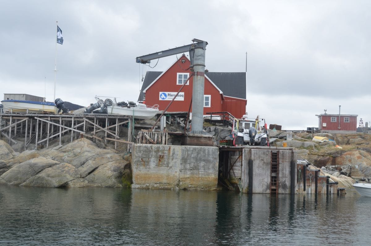

Връх на плаващ айсберг / Гърбат кит, видян от ресторанта / Малкият кей на Илиманак © Светла Стоянова
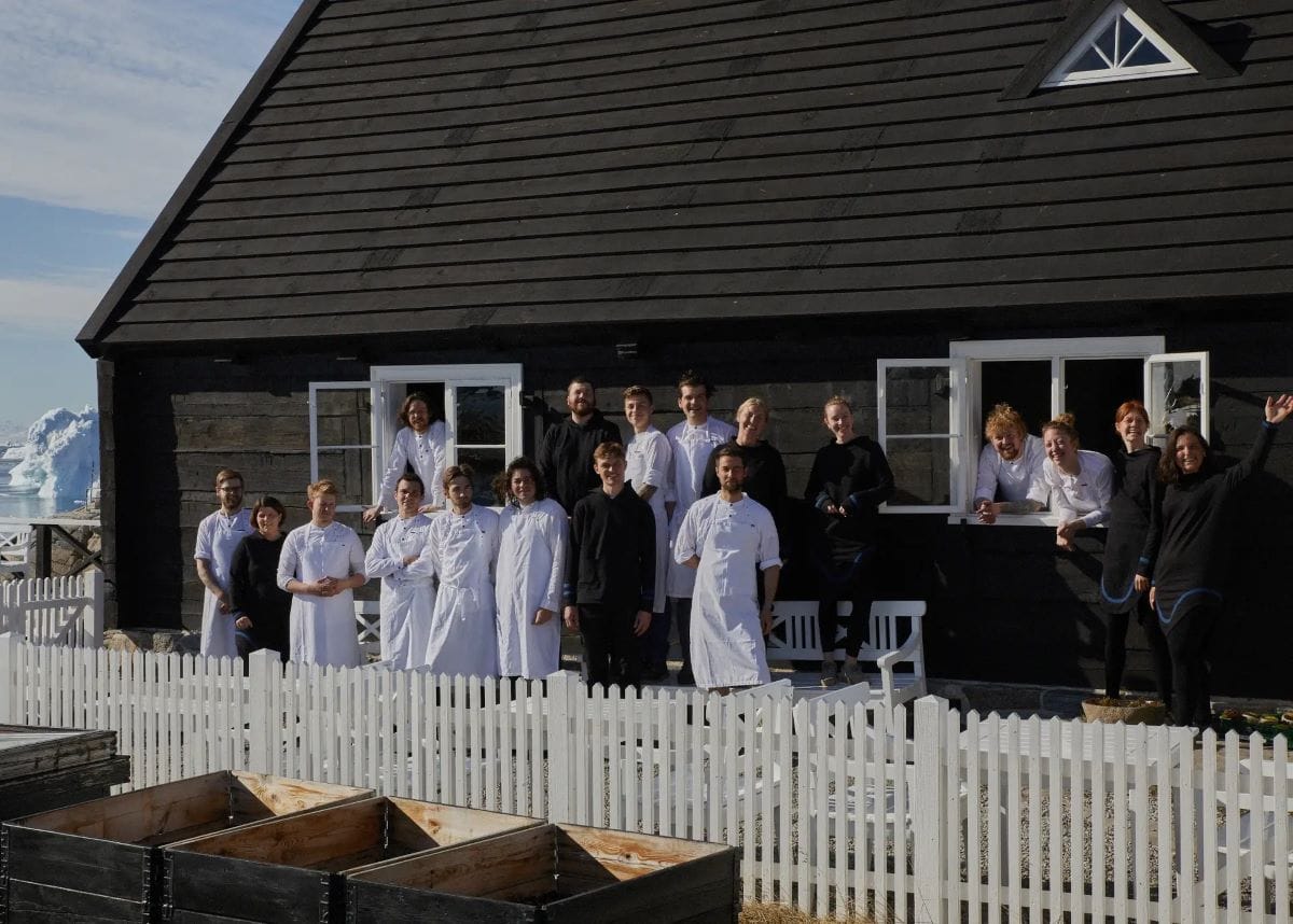
Какво означава да работиш в ресторант с две звезди „Мишлен“ на края на света?
За мен това преживяване беше изключително обогатяващо, но същевременно и просветляващо за цената на подобно заведение и неговото значение на толкова специално и отдалечено място като Гренландия.
Затова нека пристъпим в ресторанта преди пристигането на първите гости. На място ежедневно работи екип от 6–7 сервитьори и 10–15 готвачи. За да е готов салонът, масите трябва да са подредени според строг етикет: чинията да бъде на точно един палец разстояние от ръба на масата; памучната кърпа да е изгладена и сгъната по определен начин; приборите трябва да са излъскани до идеален блясък; водната чаша да е обърната с надписа към госта, така че, като отпие, да вижда марката на висококачествените чаши; свещите да са подредени в прави линии спрямо останалите елементи; столовете да са покрити със сресана овча вълна, леко отдалечени от масата; прозорците да са огледално чисти и по настолните лампи да няма нито една прашинка. Това бяха част от задачите на екипа от сервитьори, към които принадлежах и аз.
В началото ме удиви колко много видове винени чаши може да има. Доскоро за мен съществуваха само два вида тумбести чаши на столче. Но там трябваше да боравим с поне десет разновидности: за шардоне, пино ноар, ризлинг, албариньо, за такова шампанско, за онакова шампанско и какво ли още не. На всичко отгоре те бяха толкова леки, тънки и нежни, че като ги хващах, умирах от страх да не се пръснат в ръцете ми.
Понякога ми се падаше чудната задача да събирам диви цветя за украса по масите. Така за мъничко се спасявах от суматохата и с кутия в ръка късах жълти, бели и лилави цветчета в покрайнините на селото.

Друга вълнуваща част от работата е приготвянето на безалкохолните напитки: това бяха различни видове комбуча, отбрани чайове, ферментирали сокове и безалкохолни коктейли с цели парчета лед, които предварително събирахме от морето.
Готвачите на свой ред се разделят на екипи, които отговарят за определени ястия в т.нар. топла и студена кухня и през целия ден правят безкрайни заготовки за 20-степенното меню. Обслужването на гостите започва още следобед и продължава до късна вечер. Тогава се сглобяват студените ястия и се приготвят топлите.
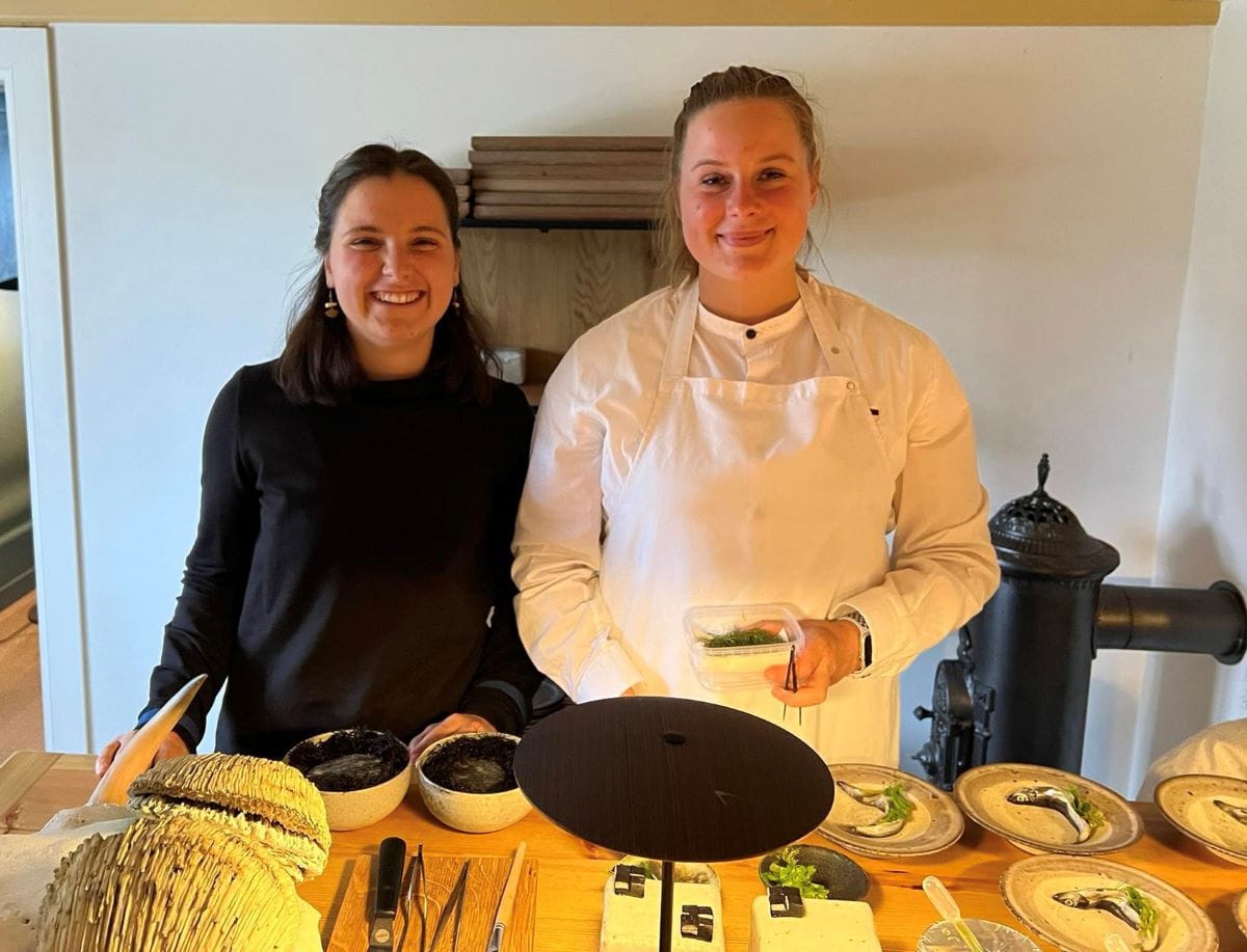
Рядко имах възможност да видя как всъщност се създават сложните специалитети, които отнасяхме по масите всяка вечер, и ме гонеше голямо любопитство. Исках да знам какво се разиграва зад кулисите, и в един от почивните си дни помолих главния готвач да ида на работа в кухнята. Въпреки първоначалната почуда той ми позволи да се включа рамо до рамо с останалите. Сутринта гордо си сложих готварската престилка и влязох в кухнята, където половината готвачи работеха с ножове от всякакъв калибър, а другата половина – с пинсети като по филмите, защото всеки детайл беше от значение.
Задачи за мен веднага се намериха и цял ден кръцках връхчетата на различни видове водорасли, учих се да изпразвам скаридени глави с пинсета, правих формички за десерта с карамелизиран лук и черен чесън, наблюдавах готвачите и разпитвах всеки кой какво прави – един завиваше малките букетчета от различни видове салати, друг разфасоваше елен, трети завиваше тънки парчета риба на рулца. Накрая съзрях и сладкаря, който използваше грамофон, макар и без плоча, заради въртеливото движение на основата, върху която с помощта на шприц правеше спираловидни бледорозови сладки от плодов целувчен крем. Разказа ми, че купили грамофона с единственото условие да може да се върти, независимо дали свири, или не. Работата кипеше, а аз наблюдавах, слушах и научавах разни истории „от кухнята“.
Освен с две звезди „Мишлен“ ресторантът бил оценен и със „зелена звезда“ за устойчивост
и в качеството си на такъв се стараел да прилага колкото може повече природосъобразни практики. Когато получил това признание, той все още бил на Фарьорските острови, където ежедневно се снабдявал с пресни продукти от морето. Освен това готвачите собственоръчно събирали килограми водорасли от брега и диворастящи подправки от поляните, като арктическа мащерка или девесил. Ресторантът бил сезонен, от май до октомври, за да бъде в хармония с намирането на сезонни продукти. Доста от ястията се приготвяли по традиционни естествени методи за консервиране чрез сушене, осоляване или ферментация на месо, риба и растителни продукти. Накрая голяма част от отпадъците се превръщала в компост.
При преместването на ресторанта в Гренландия готвачите искали да имат същите или поне подобни устойчиви порядки. Затова няколко месеца преди това главният готвач отишъл сам на проучвателно пътуване, за да опознае вкуса на инуитската кухня, да пренесе у дома колкото може повече от местните продукти и да разработи меню за предстоящия сезон в Гренландия. Целта му също била да се постарае да осигури доставчици, ловци и рибари, които да снабдяват редовно ресторанта със съответните продукти на място.
Гренландия обаче не била подготвена за подобна организация и осигуряването на редовни доставки на разнообразни продукти се оказало твърде сложно. В крайна сметка решението било да се използва огромен колкото цяла стая фризер, в който да се подреждат риби, скариди, дивеч, боровинки и всички останали нетрайни продукти. Така загубите се минимализираха. Част от неизползваната храна при приготвянето на менюто често се превръщаше в служебни вечери, а онова, което не можеше да се консумира така, се даваше на селските кучета.
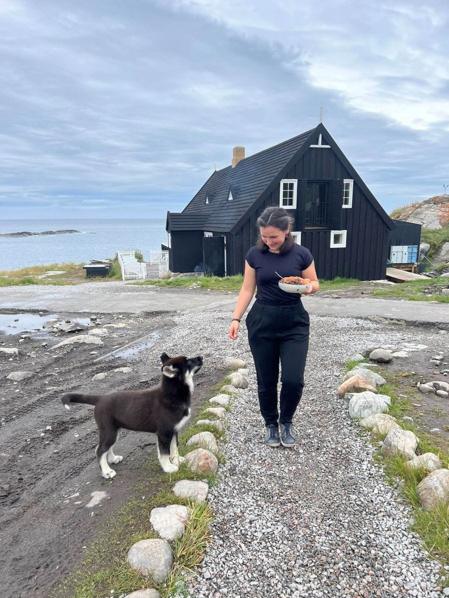
Всяка монета обаче има две страни, дори и толкова специално място като този ресторант. Уви, колкото и да претендира, че е „зелен“, все пак преместването на цяло заведение заедно с всичко необходимо за нормалното му функциониране, включващо машини, вносни продукти и вина, както и екипа от готвачи и сервитьори, а накрая и туристите, изминаващи дългия път за една вечеря, навежда на мисълта, че едва ли всичко е толкова устойчиво и природосъобразно. Аз също бях част от това и го осъзнавах на място.
Макар да се осланяше на гренландската кухня, ресторантът беше чужд за самите гренландци.
За тях беше едновременно гордост, че нещо толкова невероятно се случва и в тяхната страна, но и непонятна мистерия. Освен една миячка на чинии от селото, в екипа нямаше нито един местен, което шефовете обясниха с факта, че няма достатъчно обучени кадри от гледна точка на умения и език. Правеха се опити за известно сближаване с инуитите, но за повечето от екипа те оставаха непознати.
Що се отнася до приходите от ресторанта, те също не отиваха за подкрепа на гренландската икономика, а у фарьорския им собственик. Гости пристигаха откъде ли не – от Австралия, Сингапур, Швейцария, Дания, Франция, САЩ, но
цената на една вечеря беше висока и хората, живеещи най-близо до ресторанта, не можеха да си я позволят.
За съжаление, това става често в Гренландия – чуждестранни компании искат да черпят от нея, да разработват мини за редки метали, да сондират нефт, да ловят риба, да се възползват от природата на едно от малкото диви места на този свят.
Един познат гренландец ми каза:
По-добрата алтернатива за Гренландия е да идват хора, които са любопитни и се впечатляват от нашата страна, култура и кухня, отколкото да се увеличават добивните мини, които да съсипват природата ни.
Днес в един глобален свят е трудно някои процеси да бъдат спрени. Остава само упованието в красотата, на която все още имаме шанса да сме свидетели.
Часът е 1 през нощта и слънцето залязва. Току-що приключихме работа. Прибирайки се в съседната къща, главният готвач ми помахва, докато стоя на прозореца и съзерцавам ледниците, обагрени в светлосиньо, розово и лилаво. На неравномерни ресни повърхността на океана прелива от зеленикаво към сребристосиньо и светложълто. Прелитат птици, прибират се и те някъде вкъщи. Четири трептящи черни точици се носят ниско досами водата, еднакво отдалечени една от друга, а образите им се отразяват в гладката повърхност. Прелитащите точици стават осем.
[$] LWN.net Weekly Edition for April 18, 2024
Post Syndicated from daroc original https://lwn.net/Articles/969442/
The LWN.net Weekly Edition for April 18, 2024 is available.