Tag Archives: Architecture

New Amazon Virtual Andon 3.0 – Automate Issue Resolution via APIs and Predictive Services

Post Syndicated from Ajay Swamy original https://aws.amazon.com/blogs/architecture/new-amazon-virtual-andon-3-0-automate-issue-resolution-via-apis-and-predictive-services/

Developing a modern manufacturing enterprise requires careful thought and attention to several priorities. Predictive maintenance and issue resolution automation are likely high on your list. Maximizing your operational efficiency and optimizing output are critical in this competitive global market. As demand grows, manufacturers are under pressure to fulfill increased production needs.

A recent report from McKinsey on Industry 4.0 technologies discusses pandemic implementations such as digital issue detection and resolution. These solutions are critical for crisis response in the COVID-19 era. 30% of manufacturers have highlighted increased operational productivity, reduced time-to-market, and reduction in cost as major strategic imperatives for their Industry 4.0 transformation.

Amazon Virtual Andon 3.0 (AVA) is an Amazon Web Services (AWS) Solution that provides a scalable, digital Andon system to help detect and resolve issues. It optimizes processes, supports your transition to predictive maintenance, and helps prevent future equipment failures.

Overview of new features

AVA provides factory and fulfillment center associates with an intuitive, responsive web interface and workflow. This can be used to raise issues, route those issues to the appropriate engineers, and resolve them in a timely way. With AVA, you can associate explanatory root causes with resolved issues for more insightful reporting. Issue raising and resolution happen digitally. There’s no need for manual intervention (such as raising a manual alarm at a factory workstation.)

AVA introduces the capability to raise issues directly from devices and automated APIs. Flexible integrations can be made directly with your factory devices and systems. Additionally, the APIs integrate with Amazon Machine Learning (ML) services, such as Amazon Lookout for Equipment and Amazon Lookout for Vision. This enables you to automate ML inference into your AVA-based workflows.

With AVA 3.0, you can now monitor your factory floors for disruptions in near-real-time. You can respond and resolve issues quickly, minimizing production disruption. AVA 3.0 provides users with an analytics pipeline so you can create dashboards and custom reports.

Introducing GraphQL APIs

The solution introduces GraphQL APIs via AWS AppSync, secured through AWS Identity and Access Management (IAM) policies. This powers the web interface and functionality to create, route, and manage issues. With AVA GraphQL APIs, you can create and manage site hierarchies, devices, events, and raise and manage issues. For example, you can create an issue by calling the createIssue API to raise issues and track them to completion automatically.

createIssue
{
    id: "<string>",
    siteName: "<string>",
    areaName: "<string>",
    stationName: "<string>",
    deviceName: "<string>",
    processName: "<string>",
    eventId: "<string>",
    eventDescription: "<string>",
    eventType: "<string>",
    issueSource: "<string>",
    priority: "<string>",
    status: "<string>",
    created: "AWSDateTime",
    acknowledged: "AWSDateTime",
    closed: "AWSDateTime",
    acknowledgedTime: "<number>",
    resolutionTime: "<number>",
    createdBy: "<string>",
    additionalDetails: "<string>"
  }

Integration with Amazon Machine Learning services to raise issues automatically

With AVA APIs, you can integrate with predictive services like Amazon Lookout for Equipment (L4E). AVA provides an AWS Lambda function for detecting anomalies generated via L4E. It automatically calls the APIs to create issues for abnormal events.

When L4E detects anomalies in your machinery or production line, AVA can automatically raise issues for those anomalies (Figure 1). This gives you the visibility and tracking mechanism to ensure anomalies are resolved. You can create automated events and issues via APIs by integrating with Amazon Lookout for Equipment. You’re able to track anomalies with their details in near-real-time.

Figure 1. AVA displays anomalies raised from L4E. A prediction score of > 0 indicates that an anomaly has been detected, and AVA will raise an issue with the underlying sensor details.” width=”1063″ height=”611″></p>
<p id=Figure 1. AVA displays anomalies raised from L4E. A prediction score of > 0 indicates that an anomaly has been detected, and AVA will raise an issue with the underlying sensor details.

Direct device integration

AVA provides the capability to integrate with IoT devices via AWS IoT Core. You can configure your IoT devices to send data to the ava/issues AWS IoT Core topic. Additionally, AVA can send messages to the ava/devices AWS IoT Core topic to automatically raise issues via MQTT or HTTPS. It maps your machine name to an AVA device and a tag/value combination to an AVA event.

{
  "id": <ID!>,
  "eventId": String,
  "eventDescription": String,
  "type": String,
  "priority": String,
  "siteName": String,
  "processName": String,
  "areaName":" String,
  "stationName": String,
  "deviceName": String,
  "created": AWSDateTime,
  "acknowledged": AWSDateTime,
  "closed": AWSDateTime,
  "status": "open"
}

Analytics pipeline for custom dashboards

AVA uses Amazon DynamoDB to store factory configuration and issues data. All AVA data is exported from the DynamoDB database to an Amazon S3 bucket via an AWS Glue workflow. You can then use Amazon Athena to query underlying data and create custom reports using business intelligence (BI) solutions like Amazon QuickSight (Figure 2). With the analytics pipeline, you can create custom dashboards and monitor your factory operations holistically.

Figure 2. Custom dashboard generated via Amazon QuickSight

Figure 2. Custom dashboard generated via Amazon QuickSight

Architecture and workflow

Figure 3. AVA 3.0 architecture

Figure 3. AVA 3.0 architecture

The AWS CloudFormation template deploys the following infrastructure, shown in Figure 3:

  1. The AWS CloudFormation template provides an Amazon CloudFront web interface that deploys into an Amazon Simple Storage Service (Amazon S3) bucket configured for web hosting.
  2. An Amazon Cognito user pool allows this solution’s administrators to register users and groups using the web interface.
  3. AWS AppSync GraphQL APIs and AWS Amplify power the web interface. Amazon DynamoDB tables store the factory data.
  4. An AWS IoT rule engine helps you monitor manufacturing workstations or devices for events. It then routes the event to the correct engineer for resolution in real time.
  5. Authorized users can interact with and receive notifications from this solution. An AWS Lambda function and Amazon Simple Notification Service (Amazon SNS) send emails and SMS notifications.
  6. Issues created, acknowledged, and closed in the web interface are recorded and updated using AWS AppSync and DynamoDB.
  7. The AWS AppSync GraphQL APIs can be called directly with HTTP POST requests.
  8. If you are using L4E to monitor your machines, enter the name of the Amazon S3 bucket where inference files will be delivered in the Anomaly Detection Output Bucket CloudFormation parameter. This solution can be configured to automatically raise issues if an anomaly is detected.
  9. When the Activate Glue Workflow CloudFormation parameter is set to “Yes”, an AWS Glue workflow will be created to extract data from DynamoDB. It delivers this data via an AWS Glue Data Catalog into Amazon S3. For more information, refer to the Data Analysis section.
  10. You can use an existing SAML provider as an additional identity provider for access to this solution. You can configure the Amazon Cognito Domain Prefix, SAML Provider Name, and SAML Provider Metadata URL CloudFormation parameters. For more information, refer to SAML identity provider.

An intuitive UI with nested events

With AVA, you also can create nested events / issues, so you can more easily get to the root of the problem and resolve issues quickly. The solution builds upon the same intuitive UI as highlighted in this previous Amazon Virtual Andon blog post. In addition, it allows you to manage events granularly, create subevents, raise, and resolve issues and sub issues (Figure 4).

Figure 4. AVA allows you to raise issues and sub issues (for example, ‘Out of boxes’ allows you to specify the kind of boxes you need to resolve the issue)

Figure 4. AVA allows you to raise issues and sub issues (for example, ‘Out of boxes’ allows you to specify the kind of boxes you need to resolve the issue)

Conclusion

Amazon Virtual Andon (AVA) is a self-deployable solution that provides you the digital capability to create, route, manage, and resolve issues. With AVA, you can monitor your overall enterprise for issues and engage with the right engineers to resolve them promptly. It offers a clear, intuitive user interface and straightforward workflow to help team members resolve issues.

Get started with Amazon Virtual Andon today.

Architecture Monthly Magazine: IoT for the Edge

Post Syndicated from Jane Scolieri original https://aws.amazon.com/blogs/architecture/architecture-monthly-magazine-iot-for-the-edge/

Internet of Things (IoT) for the Edge encompasses so many devices and industries, that we couldn’t
pick just one photo for our cover. We include IoT use cases from manufacturing, fitness, ocean research, and agriculture. And these represent only a fraction of what is possible. By moving certain workloads to the edge, your devices communicate with local compute resources and can respond more quickly to changes.

AWS edge services deliver data processing, analysis, and storage close to your endpoints, allowing you to deploy APIs and tools to locations outside AWS data centers. You can harness the data generated by your IoT edge devices and enable them to act intelligently with AWS IoT services.

We’d like to thank our experts, Olawale Oladehin, Head of Worldwide Solutions Architect – IoT, Maggie Tallman, Worldwide Go-To-Market Manager – IoT & Robotics, and Richard Elberger, IoT Principal Technologist, AWS. We are also pleased to have a contribution by one of our Customers, Jaime González, Chief Technology Officer, Pentasoft. Special thanks go to Ryan Burke, Sr. Application Architect, and Channa Samynathan, Specialist Solutions Architect – IoT, for their invaluable help shepherding this issue.

Please give us your feedback! Take our survey.

You can also include your comments on the Amazon Kindle page. View past issues and reach out to [email protected] anytime with your questions and comments.

In this month’s IoT for the Edge issue:

  • Ask an Expert: Maggie Tallman, Worldwide Go-To-Market Manager – IoT & Robotics, and Olawale Oladehin, Head of Worldwide Solutions Architect – IoT
  • Customer Conversations: Jaime González, Chief Technology Officer, Pentasoft
  • Ask an Expert, Hardware Security: Richard Elberger, IoT Principal Technologist, AWS
  • Whitepaper: Security at the Edge: Core Principles
  • Case Study: Seafloor Systems Saves 4 Hours of Labor per Robot Build Using AWS IoT Greengrass
  • Implementation Guide: Monitoring River Levels Using LoRaWAN
  • Blog: Run ML inference on AWS Snowball Edge with Amazon SageMaker Edge Manager and AWS IoT Greengrass
  • Reference Architecture: Using Computer Vision for Product Quality Analysis in Plants
  • Case Study: Coca-Cola İçecek Improves Operational Performance Using AWS IoT SiteWise
  • Quick Start: The Industrial Machine Connectivity (IMC) Quick Start
  • Blog: Automated Device Provisioning to AWS IoT Core Using 1NCE Global SIM
  • Solution: Machine to Cloud Connectivity Framework
  • Reference Architecture: Predictive Equipment Health for Utilities
  • Blog: Autonomous vehicle data collection with AWS Snowcone and AWS IoT Greengrass
  • Solution: AWS Connected Vehicle Solution
  • Videos:
    • 30MHz: Building A Smart Agriculture Solution For Indoor Farms And Greenhouses On
      AWS
    • Evolving at the Edge with the AWS Snow Family
    • Data Residency at the Edge: AWS Outposts Inside Out
    • Orangetheory Fitness: Taking a Data-Driven Approach to Improving Health and Wellness (Special)
    • Data Migration and Edge Computing with the AWS Snow Family
    • All in with James Gosling: Behind the Scenes with AWS IoT Greengrass V2

Download the Magazine

How to access the magazine

View and download past issues as PDFs on the AWS Architecture Monthly webpage.
Readers in the US, UK, Germany, and France can subscribe to the Kindle version of the magazine at Kindle Newsstand.
Visit Flipboard, a personalized mobile magazine app that you can also read on your computer.
We hope you’re enjoying Architecture Monthly, and we’d like to hear from you—leave us a star rating and comment on the Amazon Kindle Newsstand page or contact us anytime at [email protected].

Disaster Recovery with AWS Managed Services, Part I: Single Region

Post Syndicated from Dhruv Bakshi original https://aws.amazon.com/blogs/architecture/disaster-recovery-with-aws-managed-services-part-i-single-region/

This 3-part blog series discusses disaster recovery (DR) strategies that you can implement to ensure your data is safe and that your workload stays available during a disaster. In Part I, we’ll discuss the single AWS Region/multi-Availability Zone (AZ) DR strategy.

The strategy outlined in this blog post addresses how to integrate AWS managed services into a single-Region DR strategy. This will minimize maintenance and operational overhead, create fault-tolerant systems, ensure high availability, and protect your data with robust backup/recovery processes. This strategy replicates workloads across multiple AZs and continuously backs up your data to another Region with point-in-time recovery, so your application is safe even if all AZs within your source Region fail.

Implementing the single Region/multi-AZ strategy

The following sections list the components of the example application presented in Figure 1, which illustrates a multi-AZ environment with a secondary Region that is strictly utilized for backups. This example architecture refers to an application that processes payment transactions that has been modernized with AMS. We’ll show you which AWS services it uses and how they work to maintain the single Region/multi-AZ strategy.

Single Region/multi-AZ with secondary Region for backups

Figure 1. Single Region/multi-AZ with secondary Region for backups

Amazon EKS control plane

Amazon Elastic Kubernetes Service (Amazon EKS) runs the Kubernetes management infrastructure across multiple AZs to eliminate a single point of failure.

This means that if your infrastructure or AZ fails, it will automatically scale control plane nodes based on load, automatically detect and replace unhealthy control plane instances, and restart them across the AZs within the Region as needed.

Amazon EKS data plane

Instead of creating individual Amazon Elastic Compute Cloud (Amazon EC2) instances, create worker nodes using an Amazon EC2 Auto Scaling group. Join the group to a cluster, and the group will automatically replace any terminated or failed nodes if an AZ fails. This ensures that the cluster can always run your workload.

Amazon ElastiCache

Amazon ElastiCache continually monitors the state of the primary node. If the primary node fails, it will promote the read replica with the least replication lag to primary. A replacement read replica is then created and provisioned in the same AZ as the failed primary. This is to ensure high availability of the service and application.

An ElastiCache for Redis (cluster mode disabled) cluster with multiple nodes has three types of endpoints: the primary endpoint, the reader endpoint and the node endpoints. The primary endpoint is a DNS name that always resolves to the primary node in the cluster.

Amazon Redshift

Currently, Amazon Redshift only supports single-AZ deployments. Although there are ways to work around this, we are focusing on cluster relocation. Parts II and III of this series will show you how to implement this service in a multi-Region DR deployment.

Cluster relocation enables Amazon Redshift to move a cluster to another AZ with no loss of data or changes to your applications. When Amazon Redshift relocates a cluster to a new AZ, the new cluster has the same endpoint as the original cluster. Your applications can reconnect to the endpoint and continue operations without modifications or loss of data.

Note: Amazon Redshift may also relocate clusters in non-AZ failure situations, such as when issues in the current AZ prevent optimal cluster operation or to improve service availability.

Amazon OpenSearch Service

Deploying your data nodes into three AZs with Amazon OpenSearch Service (formerly Amazon Elasticsearch Service) can improve the availability of your domain and increase your workload’s tolerance for AZ failures.

Amazon OpenSearch Service automatically deploys into three AZs when you select a multi-AZ deployment. This distribution helps prevent cluster downtime if an AZ experiences a service disruption. When you deploy across three AZs, Amazon OpenSearch Service distributes master nodes equally across all three AZs. That way, in the rare event of an AZ disruption, two master nodes will still be available.

Amazon OpenSearch Service also distributes primary shards and their corresponding replica shards to different zones. In addition to distributing shards by AZ, Amazon OpenSearch Service distributes them by node. When you deploy the data nodes across three AZs with one replica enabled, shards are distributed across the three AZs.

Note: For more information on multi-AZ configurations, please refer to the AZ disruptions table.

Amazon RDS PostgreSQL

Amazon Relational Database Service (Amazon RDS) handles failovers automatically so you can resume database operations as quickly as possible.

In a Multi-AZ deployment, Amazon RDS automatically provisions and maintains a synchronous standby replica in a different AZ. The primary DB instance is synchronously replicated across AZs to a standby replica. If an AZ or infrastructure fails, Amazon RDS performs an automatic failover to the standby. This minimizes the disruption to your applications without administrative intervention.

Backing up data across Regions

Here is how the managed services back up data to a secondary Region:

  • Manage snapshots of persistent volumes for Amazon EKS with Velero. Amazon Simple Storage Service (Amazon S3) stores these snapshots in an S3 bucket in the primary Region. Amazon S3 replicates these snapshots to an S3 bucket in another Region via S3 cross-Region replication.
  • Create a manual snapshot of Amazon OpenSearch Service clusters, which are stored in a registered repository like Amazon S3. You can do this manually or automate it via an AWS Lambda function, which automatically and asynchronously copy objects across Regions.
  • Use manual backups and copy API calls for Amazon ElastiCache to establish a snapshot and restore strategy in a secondary Region. You can manually back your data up to an S3 bucket or automate the backup via Lambda. Once your data is backed up, a snapshot of the ElastiCache cluster will be stored in an S3 bucket. Then S3 cross-Region replication will asynchronously copy the backup to an S3 bucket in a secondary Region.
  • Take automatic, incremental snapshots of your data periodically with Amazon Redshift and save them to Amazon S3. You can precisely control when snapshots are taken and can create a snapshot schedule and attach it to one or more clusters. You can also configure a cross-Region snapshot copy, which automatically copies your automated and manual snapshots to another Region.
  • Use AWS Backup to support AWS resources and third-party applications. AWS Backup copies RDS backups to multiple Regions on demand or automatically as part of a scheduled backup plan.

Note: You can add a layer of protection to your backups through AWS Backup Vault Lock and S3 Object Lock.

Conclusion

The single Region/multi-AZ strategy safeguards your workloads against a disaster that disrupts an Amazon data center by replicating workloads across multiple AZs in the same Region. This blog shows you how AWS managed services automatically fails over between AZs without interruption when experiencing a localized disaster, and how backups to a separate Region ensure data protection.

In the next post, we will discuss a multi-Region warm standby strategy for the same application stack illustrated in this post.

Related information

Field Notes: Clear Unused AWS SSO Mappings Automatically During AWS Control Tower Upgrades

Post Syndicated from Gaurav Gupta original https://aws.amazon.com/blogs/architecture/field-notes-clear-unused-aws-sso-mappings-automatically-during-aws-control-tower-upgrades/

Increasingly organizations are using AWS Control Tower to manage their multiple accounts as well as an external third-party identity source for their federation needs. Cloud architects who use these external identity sources, needed an automated way to clear the unused maps created by AWS Control Tower landing zone as part of the launch, or during update and repair operations. Though the AWS SSO mappings are inaccessible once the external identity source is configured, customers prefer to clear any unused mappings in the directory.

You can remove the permissions sets and mappings that AWS Control Tower deployment creates in AWS SSO. However, when the landing zone is updated or repaired, the default permission sets and mappings are recreated in AWS SSO. In this blog post, we show you how to use AWS Control Tower Lifecycle events to automatically remove these permission sets and mappings when AWS Control Tower is upgraded or repaired. An AWS Lambda function runs on every upgrade and automatically removes the permission sets and mappings.

Overview of solution

Using this CloudFormation template, you can deploy the solution that automatically removes the AWS SSO permission sets and mappings when you upgrade your AWS Control Tower environment. We use AWS CloudFormation, AWS Lambda, AWS SSO and Amazon CloudWatch services to implement this solution.

Figure 1 - Architecture showing how AWS services are used to automatically remove the AWS SSO permission sets and mappings when you upgrade your AWS Control Tower environment

Figure 1 – Architecture showing how AWS services are used to automatically remove the AWS SSO permission sets and mappings when you upgrade your AWS Control Tower environment

To clear the AWS SSO entities and leave the service enabled with no active mappings, we recommend the following steps. This is mainly for those who do not want to use the default AWS SSO deployed by AWS Control Tower.

  • Log in to the AWS Control Tower Management Account and make sure you are in the AWS Control Tower Home Region.
  • Launch AWS CloudFormation stack, which creates:
    • An AWS Lambda function that:
      • Checks/Delete(s) the permission sets mappings created by AWS Control Tower, and
      • Deletes the permission sets created by AWS Control Tower.
  • An AWS IAM role that is assigned to the preceding AWS Lambda Function with minimum required permissions.
  • An Amazon CloudWatch Event Rule that is invoked upon UpdateLandingZone API and triggers the ClearMappingsLambda Lambda function

Prerequisites

For this walkthrough, you should have the following prerequisites:

  • Administrator access to AWS Control Tower management account

Walkthrough

  1. Log in to the AWS account where AWS Control Tower is deployed.
  2. Make sure you are in the home Region of AWS Control Tower.
  3. Deploy the provided CloudFormation template.
    • Download the CloudFormation template.
    • Select AWS CloudFormation service in the AWS Console
    • Select Create Stack and select With new resources (standard)
    • Upload the template file downloaded in Step 1
    • Enter the stack name and choose Next
    • Use the default values in the next page and choose Next
    • Choose Create Stack

By default, in your AWS Control Tower Landing Zone you will see the permission sets and mappings in your AWS SSO service page as shown in the following screenshots:

Figure 2 – Permission sets created by AWS Control Tower

Figure 3 – Account to Permission set mapping created by AWS Control Tower

Now, you can update the AWS Control Tower Landing Zone which will invoke the Lambda function deployed using the CloudFormation template.

Steps to update/repair Control Tower:

  1. Log in to the AWS account where AWS Control Tower is deployed.
  2. Select Landing zone settings from the left-hand pane of the Control Tower dashboard
  3. Select the latest version as seen in the screenshot below.
  4. Select Repair or Update, whichever option is available.
  5. Select Update Landing Zone.

Figure 4 – Updating AWS Control Tower Landing zone

Once the update is complete, you can go to AWS SSO service page and check that the permission sets and the mappings have been removed as shown in the following screenshots:

Figure 5 -Permission sets cleared automatically after Landing zone update

Figure 6 -Mappings cleared after Landing zone update

Cleaning up

If you are only testing this solution, make sure to delete the CloudFormation template, which will remove the relevant resources to stop incurring charges.

Conclusion

In this post, we provided a solution to clear AWS SSO Permission Sets and Mappings when you upgrade your AWS Control Tower Landing Zone. Remember, AWS SSO permission sets are added every time you upgrade AWS Control Tower Landing Zone. With this this solution you don’t have to manage any settings since the AWS Lambda function runs on every upgrade and removes the permission sets and mappings.

Give it a try and let us know your thoughts in the comments!

Field Notes provides hands-on technical guidance from AWS Solutions Architects, consultants, and technical account managers, based on their experiences in the field solving real-world business problems for customers.

Migrating to an Amazon Redshift Cloud Data Warehouse from Microsoft APS

Post Syndicated from Sudarshan Roy original https://aws.amazon.com/blogs/architecture/migrating-to-an-amazon-redshift-cloud-data-warehouse-from-microsoft-aps/

Before cloud data warehouses (CDWs), many organizations used hyper-converged infrastructure (HCI) for data analytics. HCIs pack storage, compute, networking, and management capabilities into a single “box” that you can plug into your data centers. However, because of its legacy architecture, an HCI is limited in how much it can scale storage and compute and continue to perform well and be cost-effective. Using an HCI can impact your business’s agility because you need to plan in advance, follow traditional purchase models, and maintain unused capacity and its associated costs. Additionally, HCIs are often proprietary and do not offer the same portability, customization, and integration options as with open-standards-based systems. Because of their proprietary nature, migrating HCIs to a CDW can present technical hurdles, which can impact your ability to realize the full potential of your data.

One of these hurdles includes using AWS Schema Conversion Tool (AWS SCT). AWS SCT is used to migrate data warehouses, and it supports several conversions. However, when you migrate Microsoft’s Analytics Platform System (APS) SQL Server Parallel Data Warehouse (PDW) platform using only AWS SCT, it results in connection errors due to the lack of server-side cursor support in Microsoft APS. In this blog post, we show you three approaches that use AWS SCT combined with other AWS services to migrate Microsoft’s Analytics Platform System (APS) SQL Server Parallel Data Warehouse (PDW) HCI platform to Amazon Redshift. These solutions will help you overcome elasticity, scalability, and agility constraints associated with proprietary HCI analytics platforms and future proof your analytics investment.

AWS Schema Conversion Tool

Though using AWS SCT only will result in server-side cursor errors, you can pair it with other AWS services to migrate your data warehouses to AWS. AWS SCT converts source database schema and code objects, including views, stored procedures, and functions, to be compatible with a target database. It highlights objects that require manual intervention. You can also scan your application source code for embedded SQL statements as part of database-schema conversion project. During this process, AWS SCT optimizes cloud-native code by converting legacy Oracle and SQL Server functions to their equivalent AWS service. This helps you modernize applications simultaneously. Once conversion is complete, AWS SCT can also migrate data.

Figure 1 shows a standard AWS SCT implementation architecture.

AWS SCT migration approach

Figure 1. AWS SCT migration approach

The next section shows you how to pair AWS SCT with other AWS services to migrate a Microsoft APS PDW to Amazon Redshift CDW. We prove you a base approach and two extensions to use for data warehouses with larger datasets and longer release outage windows.

Migration approach using SQL Server on Amazon EC2

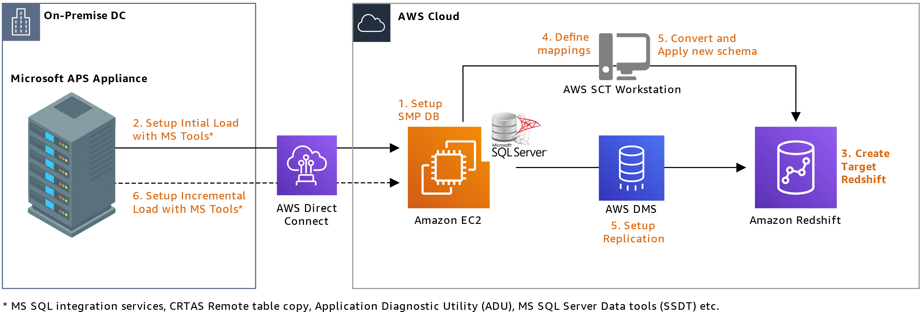
The base approach uses Amazon Elastic Compute Cloud (Amazon EC2) to host a SQL Server in a symmetric multi-processing (SMP) architecture that is supported by AWS SCT, as opposed to Microsoft’s APS PDW’s massively parallel processing (MPP) architecture. By changing the warehouse’s architecture from MPP to SMP and using AWS SCT, you’ll avoid server-side cursor support errors.

Here’s how you’ll set up the base approach (Figure 2):

  1. Set up the SMP SQL Server on Amazon EC2 and AWS SCT in your AWS account.
  2. Set up Microsoft tools, including SQL Server Data Tools (SSDT), remote table copy, and SQL Server Integration Services (SSIS).
  3. Use the Application Diagnostic Utility (ADU) and SSDT to connect and extract table lists, indexes, table definitions, view definitions, and stored procedures.
  4. Generate data description languages (DDLs) using step 3 outputs.
  5. Apply these DDLs to the SMP SQL Server on Amazon EC2.
  6. Run AWS SCT against the SMP SQL database to begin migrating schema and data to Amazon Redshift.
  7. Extract data using remote table copy from source, which copies data into the SMP SQL Server.
  8. Load this data into Amazon Redshift using AWS SCT or AWS Database Migration Service (AWS DMS).
  9. Use SSIS to load delta data from source to the SMP SQL Server on Amazon EC2.
Base approach using SMP SQL Server on Amazon EC2

Figure 2. Base approach using SMP SQL Server on Amazon EC2

Extending the base approach

The base approach overcomes server-side issues you would have during a direct migration. However, many organizations host terabytes (TB) of data. To migrate such a large dataset, you’ll need to adjust your approach.

The following sections extend the base approach. They still use the base approach to convert the schema and procedures, but the dataset is handled via separate processes.

Extension 1: AWS Snowball Edge

Note: AWS Snowball Edge is a Region-specific service. Verify that the service is available in your Region before planning your migration. See Regional Table to verify availability.

Snowball Edge lets you transfer large datasets to the cloud at faster-than-network speeds. Each Snowball Edge device can hold up to 100 TB and uses 256-bit encryption and an industry-standard Trusted Platform Module to ensure security and full chain-of-custody for your data. Furthermore, higher volumes can be transferred by clustering 5–10 devices for increased durability and storage.

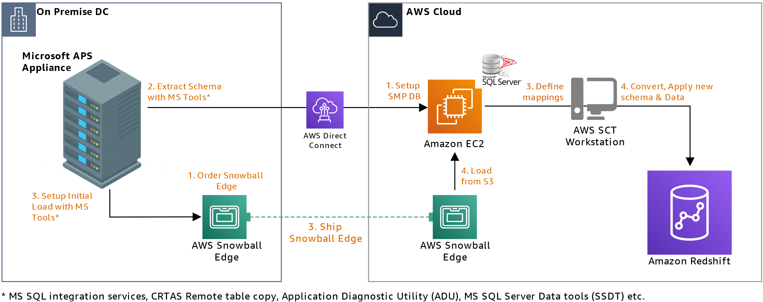
Extension 1 enhances the base approach to allow you to transfer large datasets (Figure 3) while simultaneously setting up an SMP SQL Server on Amazon EC2 for delta transfers. Here’s how you’ll set it up:

  1. Once Snowball Edge is enabled in the on-premises environment, it allows data transfer via network file system (NFS) endpoints. The device can then be used with standard Microsoft tools like SSIS, remote table copy, ADU, and SSDT.
  2. While the device is being shipped back to an AWS facility, you’ll set up an SMP SQL Server database on Amazon EC2 to replicate the base approach.
  3. After your data is converted, you’ll apply a converted schema to Amazon Redshift.
  4. Once the Snowball Edge arrives at the AWS facility, data is transferred to the SMP SQL Server database.
  5. You’ll subsequently run schema conversions and initial and delta loads per the base approach.
Solution extension that uses Snowball Edge for large datasets

Figure 3. Solution extension that uses Snowball Edge for large datasets

Note: Where sequence numbers overlap in the diagram is a suggestion to possible parallel execution

Extension 1 transfers initial load and later applies delta load. This adds time to the project because of longer cutover release schedules. Additionally, you’ll need to plan for multiple separate outages, Snowball lead times, and release management timelines.

Note that not all analytics systems are classified as business-critical systems, so they can withstand a longer outage, typically 1-2 days. This gives you an opportunity to use AWS DataSync as an additional extension to complete initial and delta load in a single release window.

Extension 2: AWS DataSync

DataSync speeds up data transfer between on-premises environments and AWS. It uses a purpose-built network protocol and a parallel, multi-threaded architecture to accelerate your transfers.

Figure 4 shows the solution extension, which works as follows:

  1. Create SMP MS SQL Server on EC2 and the DDL, as shown in the base approach.
  2. Deploy DataSync agent(s) in your on-premises environment.
  3. Provision and mount an NFS volume on the source analytics platform and DataSync agent(s).
  4. Define a DataSync transfer task after the agents are registered.
  5. Extract initial load from source onto the NFS mount that will be uploaded to Amazon Simple Storage Service (Amazon S3).
  6. Load data extracts into the SMP SQL Server on Amazon EC2 instance (created using base approach).
  7. Run delta loads per base approach, or continue using solution extension for delta loads.
Solution extension that uses DataSync for large datasets

Figure 4. Solution extension that uses DataSync for large datasets

Note: where sequence numbers overlap in the diagram is a suggestion to possible parallel execution

Transfer rates for DataSync depend on the amount of data, I/O, and network bandwidth available. A single DataSync agent can fully utilize a 10 gigabit per second (Gbps) AWS Direct Connect link to copy data from on-premises to AWS. As such, depending on initial load size, transfer window calculations must be done prior to finalizing transfer windows.

Conclusion

The approach and its extensions mentioned in this blog post provide mechanisms to migrate your Microsoft APS workloads to an Amazon Redshift CDW. They enable elasticity, scalability, and agility for your workload to future proof your analytics investment.

Related information

Running a Cost-effective NLP Pipeline on Serverless Infrastructure at Scale

Post Syndicated from Eitan Sela original https://aws.amazon.com/blogs/architecture/running-a-cost-effective-nlp-pipeline-on-serverless-infrastructure-at-scale/

Amenity Analytics develops enterprise natural language processing (NLP) platforms for the finance, insurance, and media industries that extract critical insights from mountains of documents. We provide a scalable way for businesses to get a human-level understanding of information from text.

In this blog post, we will show how Amenity Analytics improved the continuous integration (CI) pipeline speed by 15x. We hope that this example can help other customers achieve high scalability using AWS Step Functions Express.

Amenity Analytics’ models are developed using both a test-driven development (TDD) and a behavior-driven development (BDD) approach. We verify the model accuracy throughout the model lifecycle—from creation to production, and on to maintenance.

One of the actions in the Amenity Analytics model development cycle is backtesting. It is an important part of our CI process. This process consists of two steps running in parallel:

  • Unit tests (TDD): checks that the code performs as expected
  • Backtesting tests (BDD): validates that the precision and recall of our models is similar or better than previous

The backtesting process utilizes hundreds of thousands of annotated examples in each “code build.” To accomplish this, we initially used the AWS Step Functions default workflow. AWS Step Functions is a low-code visual workflow service used to orchestrate AWS services, automate business processes, and build serverless applications. Workflows manage failures, retries, parallelization, service integrations, and observability.

Challenge with the existing Step Functions solution

We found that Step Functions standard workflow has a bucket of 5,000 state transitions with a refill rate of 1,500. Each annotated example has ~10 state transitions. This creates millions of state transitions per code build. Since state transitions are limited and couldn’t be increased to our desired amount, we often faced delays and timeouts. Developers had to coordinate their work with each other, which inevitably slowed down the entire development cycle.

To resolve these challenges, we migrated from Step Functions standard workflows to Step Functions Express workflows, which have no limits on state transitions. In addition, we changed the way each step in the pipeline is initiated, from an async call to a sync API call.

Step Functions Express workflow solution

When a model developer merges their new changes, the CI process starts the backtesting for all existing models.

  • Each model is checked to see if the annotated examples were already uploaded and saved in the Amazon Simple Storage Service (S3) cache. The check is made by a unique key representing the list of items. Once a model is reviewed, the review items will rarely be changed.
  • If the review items haven’t been uploaded yet, it uploads them and initiates an unarchive process. This way the review items can be used in the next phase.
  • When the items are uploaded, an API call is invoked using Amazon API Gateway with the review items keys, see Figure 1.
  • The request is forwarded to an AWS Lambda function. It is responsible for validating the request and sending a job message to an Amazon Simple Queue Service (SQS) queue.
  • The SQS messages are consumed by concurrent Lambda functions, which synchronously invoke a Step Function. The number of Lambda functions are limited to ensure that they don’t exceed their limit in the production environment.
  • When an item is finished in the Step Function, it creates an SQS notification message. This message is inserted into a queue and consumed as a message batch by a Lambda function. The function then sends an AWS IoT message containing all relevant messages for each individual user.
Figure 1. Step Functions Express workflow solution

Figure 1. Step Functions Express workflow solution

Main Step Function Express workflow pipeline

Step Functions Express supports only sync calls. Therefore, we replaced the previous async Amazon Simple Notification Service (SNS) and Amazon SQS, with sync calls to API Gateway.

Figure 2 shows the workflow for a single document in Step Function Express:

  1. Generate a document ID for the current iteration
  2. Perform base NLP analysis by calling another Step Function Express wrapped by an API Gateway
  3. Reformat the response to be the same as all other “logic” steps results
  4. Verify the result by the “Choice” state – if failed go to end, otherwise, continue
  5. Perform the Amenity core NLP analysis in three model invocations: Group, Patterns, and Business Logic (BL)
  6. For each of the model runtime steps:
    • Check if the result is correct
    • If failed, go to end, otherwise continue
  7. Return a formatted result at the end
Figure 2. Workflow for a single document

Figure 2. Workflow for a single document

Base NLP analysis Step Function Express

For our base NLP analysis, we use Spacy. Figure 3 shows how we used it in Step Functions Express:

  1. Confirm if text exists in cache (this means it has been previously analyzed)
  2. If it exists, return the cached result
  3. If it doesn’t exist, split the text to a manageable size (Spacy has text size limitations)
  4. All the texts parts are analyzed in parallel by Spacy
  5. Merge the results into a single, analyzed document and save it to the cache
  6. If there was an exception during the process, it is handled in the “HandleStepFunctionExceptionState”
  7. Send a reference to the analyzed document if successful
  8. Send an error message if there was an exception
Figure 3. Base NLP analysis for a single document

Figure 3. Base NLP analysis for a single document

Results

Our backtesting migration was deployed on August 10, and unit testing migration on September 14. After the first migration, the CI was limited by the unit tests, which took ~25 minutes. When the second migration was deployed, the process time was reduced to ~6 minutes (P95).

Figure 4. Process time reduced from 50 minutes to 6 minutes

Figure 4. Process time reduced from 50 minutes to 6 minutes

Conclusion

By migrating from standard Step Functions to Step Functions Express, Amenity Analytics increased processing speed 15x. A complete pipeline that used to take ~45 minutes with standard Step Functions, now takes ~3 minutes using Step Functions Express. This migration removed the need for users to coordinate workflow processes to create a build. Unit testing (TDD) went from ~25 mins to ~30 seconds. Backtesting (BDD) went from taking more than 1 hour to ~6 minutes.

Switching to Step Functions Express allows us to focus on delivering business value faster. We will continue to explore how AWS services can help us drive more value to our users.

For further reading:

Batch Inference at Scale with Amazon SageMaker

Post Syndicated from Ramesh Jetty original https://aws.amazon.com/blogs/architecture/batch-inference-at-scale-with-amazon-sagemaker/

Running machine learning (ML) inference on large datasets is a challenge faced by many companies. There are several approaches and architecture patterns to help you tackle this problem. But no single solution may deliver the desired results for efficiency and cost effectiveness. In this blog post, we will outline a few factors that can help you arrive at the most optimal approach for your business. We will illustrate a use case and architecture pattern with Amazon SageMaker to perform batch inference at scale.

ML inference can be done in real time on individual records, such as with a REST API endpoint. Inference can also be done in batch mode as a processing job on a large dataset. While both approaches push data through a model, each has its own target goal when running inference at scale.

With real-time inference, the goal is usually to optimize the number of transactions per second that the model can process. With batch inference, the goal is usually tied to time constraints and the service-level agreement (SLA) for the job. Table 1 shows the key attributes of real-time, micro-batch, and batch inference scenarios.

Real Time Micro Batch Batch
Execution Mode
Synchronous Synchronous/Asynchronous Asynchronous
Prediction Latency
Subsecond Seconds to minutes Indefinite
Data Bounds Unbounded/stream Bounded Bounded
Execution Frequency
Variable Variable Variable/fixed
Invocation Mode
Continuous stream/API calls Event-based Event-based/scheduled
Examples Real-time REST API endpoint Data analyst running a SQL UDF Scheduled inference job

Table 1. Key characteristics of real-time, micro-batch, and batch inference scenarios

Key considerations for batch inference jobs

Batch inference tasks are usually good candidates for horizontal scaling. Each worker within a cluster can operate on a different subset of data without the need to exchange information with other workers. AWS offers multiple storage and compute options that enable horizontal scaling. Table 2 shows some key considerations when architecting for batch inference jobs.

  • Model type and ML framework. Models built with frameworks such as XGBoost and SKLearn require smaller compute instances. Those built with deep learning frameworks, such as TensorFlow and PyTorch require larger ones.
  • Complexity of the model. Simple models can run on CPU instances while more complex ensemble models and large-scale deep learning models can benefit from GPU instances.
  • Size of the inference data. While all approaches work on small datasets, larger datasets come with a unique set of challenges. The storage system must provide sufficient throughput and I/O to reliably run the inference workload.
  • Inference frequency and job concurrency. The volume of jobs within a fixed interval of time is an important consideration to address Service Quotas. The frequency and SLA requirements also proportionally impact the number of concurrent jobs. This might create additional pressure on the underlying Service Quotas.
ML Framework Model Complexity
Inference Data Size
Inference Frequency
Job Concurrency
  • Traditional
    • XGBoost
    • SKLearn
  • Deep Learning
    • Tensorflow
    • PyTorch
  • Low (linear models)
  • Medium (complex ensemble models)
  • High (large scale DL models)
  • Small (<1 GB)
  • Medium (<100 GB)
  • Large (<1 TB)
  • Hyperscale (>1 TB)
  • Hourly
  • Daily
  • Weekly
  • Monthly
  • 1
  • <10
  • <100
  • >100

Table 2. Key considerations when architecting for batch inference jobs

Real world Batch Inference use case and architecture

Often customers in certain domains such as advertising and marketing or healthcare must make predictions on hyperscale datasets. This requires deploying an inference pipeline that can complete several thousand inference jobs on extremely large datasets. The individual models used are typically of low complexity from a compute perspective. They could include a combination of various algorithms implemented in scikit-learn, XGBoost, and TensorFlow, for example. Most of the complexity in these use cases stems from large volumes of data and the number of concurrent jobs that must run to meet the service level agreement (SLA).

The batch inference architecture for these requirements typically is composed of three layers:

  • Orchestration layer. Manages the submission, scheduling, tracking, and error handling of individual jobs or multi-step pipelines
  • Storage layer. Stores the data that will be inferenced upon
  • Compute layer. Runs the inference job

There are several AWS services available that can be used for each of these architectural layers. The architecture in Figure 1 illustrates a real world implementation. Amazon SageMaker Processing and training services are used for compute layer and Amazon S3 for the storage layer. Amazon Managed Workflows for Apache Airflow (MWAA) and Amazon DynamoDB are used for the orchestration and job control layer.

Figure 1. Architecture for batch inference at scale with Amazon SageMaker

Figure 1. Architecture for batch inference at scale with Amazon SageMaker

Orchestration and job control layer. Apache Airflow is used to orchestrate the training and inference pipelines with job metadata captured into DynamoDB. At each step of the pipeline, Airflow updates the status of each model run. A custom Airflow sensor polls the status of each pipeline. It advances the pipeline with the successful completion of each step, or resubmits a job in case of failure.

Compute layer. SageMaker processing is used as the compute option for running the inference workload. SageMaker has a purpose-built batch transform feature for running batch inference jobs. However, this feature often requires additional pre and post-processing steps to get the data into the appropriate input and output format. SageMaker Processing offers a general purpose managed compute environment to run a custom batch inference container with a custom script. In the architecture, the processing script takes the input location of the model artifact generated by a SageMaker training job and the location of the inference data, and performs pre and post-processing along with model inference.

Storage layer. Amazon S3 is used to store the large input dataset and the output inference data. The ShardedByS3Key data distribution strategy distributes the files across multiple nodes within a processing cluster. With this option enabled, SageMaker Processing will automatically copy a different subset of input files into each node of the processing job. This way you can horizontally scale batch inference jobs by requesting a higher number of instances when configuring the job.

One caveat of this approach is that while many ML algorithms utilize multiple CPU cores during training, only one core is utilized during inference. This can be rectified by using Python’s native concurrency and parallelism frameworks such concurrent.futures. The following pseudo-code illustrates how you can distribute the inference workload across all instance cores. This assumes the SageMaker Processing job has been configured to copy the input files into the /opt/ml/processing/input directory.

from concurrent.futures import ProcessPoolExecutor, as_completed
from multiprocessing import cpu_count
import os
from glob import glob
import pandas as pd

def inference_fn(model_dir, file_path, output_dir):

model = joblib.load(f"{model_dir}/model.joblib")
data = pd.read_parquet(file_path)
data["prediction"] = model.predict(data)

output_path = f"{output_dir}/{os.path.basename(file_path)}"

data.to_parquet(output_path)

return output_path

input_files = glob("/opt/ml/processing/input/*")
model_dir = "/opt/ml/model"
output_dir = "/opt/ml/output"

with ProcessPoolExecutor(max_workers=cpu_count()) as executor:
futures = [executor.submit(inference_fn, model_dir, file_path, output_dir) for file in input_files]

results =[]
for future in as_completed(futures):
results.append(future.result())

Conclusion

In this blog post, we described ML inference options and use cases. We primarily focused on batch inference and reviewed key challenges faced when performing batch inference at scale. We provided a mental model of some key considerations and best practices to consider as you make various architecture decisions. We illustrated these considerations with a real world use case and an architecture pattern to perform batch inference at scale. This pattern can be extended to other choices of compute, storage, and orchestration services on AWS to build large-scale ML inference solutions.

More information:

Migrate your Applications to Containers at Scale

Post Syndicated from John O'Donnell original https://aws.amazon.com/blogs/architecture/migrate-your-applications-to-containers-at-scale/

AWS App2Container is a command line tool that you can install on a server to automate the containerization of applications. This simplifies the process of migrating a single server to containers. But if you have a fleet of servers, the process of migrating all of them could be quite time-consuming. In this situation, you can automate the process using App2Container. You’ll then be able to leverage configuration management tools such as Chef, Ansible, or AWS Systems Manager. In this blog, we will illustrate an architecture to scale out App2Container, using AWS Systems Manager.

Why migrate to containers?

Organizations can move to secure, low-touch services with Containers on AWS. A container is a lightweight, standalone collection of software that includes everything needed to run an application. This can include code, runtime, system tools, system libraries, and settings. Containers provide logical isolation and will always run the same, regardless of the host environment.

If you are running a .NET application hosted on Windows Internet Information Server (IIS), when it reaches end of life (EOL) you have two options. Either migrate entire server platforms, or re-host websites on other hosting platforms. Both options require manual effort and are often too complex to implement for legacy workloads. Once workloads have been migrated, you must still perform costly ongoing patching and maintenance.

Modernize with AWS App2Container

Containers can be used for these legacy workloads via AWS App2Container. AWS App2Container is a command line interface (CLI) tool for modernizing .NET and Java applications into containerized applications. App2Container analyzes and builds an inventory of all applications running in virtual machines, on-premises, or in the cloud. App2Container reduces the need to migrate the entire server OS, and moves only the specific workloads needed.

After you select the application you want to containerize, App2Container does the following:

  • Packages the application artifact and identified dependencies into container images
  • Configures the network ports
  • Generates the infrastructure, Amazon Elastic Container Service (ECS) tasks, and Kubernetes pod definitions

App2Container has a specific set of steps and requirements you must follow to create container images:

  1. Create an Amazon Simple Storage Service (S3) bucket to store your artifacts generated from each server.
  2. Create an AWS Identity and Access Management (IAM) user that has access to the Amazon S3 buckets and a designated Amazon Elastic Container Registry (ECR).
  3. Deploy a worker node as an Amazon Elastic Compute Cloud (Amazon EC2) instance. This will include a compatible operating system, which will take the artifacts and convert them into containers.
  4. Install the App2Container agent on each server that you want to migrate.
  5. Run a set of commands on each server for each application that you want to convert into a container.
  6. Run the commands on your worker node to perform the containerization and deployment.

Following, we will introduce a way to automate App2Container to reduce the time needed to deploy and scale this functionality throughout your environment.

Scaling App2Container

AWS App2Container streamlines the process of containerizing applications on a single server. For each server you must install the App2Container agent, initialize it, run an inventory, and run an analysis. But you can save time when containerizing a fleet of machines by automation, using AWS Systems Manager. AWS Systems Manager enables you to create documents with a set of command line steps that can be applied to one or more servers.

App2Container also supports setting up a worker node that can consume the output of the App2Container analysis step. This can be deployed to the new containerized version of the applications. This allows you to follow the security best practice of least privilege. Only the worker node will have permissions to deploy containerized applications. The migrating servers will need permissions to write the analysis output into an S3 bucket.

Separate the App2Container process into two parts to use the worker node.

  • Analysis. This runs on the target server we are migrating. The results are output into S3.
  • Deployment. This runs on the worker node. It pushes the container image to Amazon ECR. It can deploy a running container to either Amazon ECS or Amazon Elastic Kubernetes Service (EKS).
Figure 1. App2Container scaling architecture overview

Figure 1. App2Container scaling architecture overview

Architectural walkthrough

As you can see in Figure 1, we need to set up an Amazon EC2 instance as the worker node, an S3 bucket for the analysis output, and two AWS Systems Manager documents. The first document is run on the target server. It will install App2Container and run the analysis steps. The second document is run on the worker node and handles the deployment of the container image.
The AWS Systems Manager targets one or many hosts, enabling you to run the analysis step in parallel for multiple servers. Results and artifacts such as files or .Net assembly code, are sent to the preconfigured Amazon S3 bucket for processing as shown in Figure 2.

Figure 2. Container migration target servers

Figure 2. Container migration target servers

After the artifacts have been generated, a second document can be run against the worker node. This scans all files in the Amazon S3 bucket, and workloads are automatically containerized. The resulting images are pushed to Amazon ECR, as shown in Figure 3.

Figure 3. Container migration conversion

Figure 3. Container migration conversion

When this process is completed, you can then choose how to deploy these images, using Amazon ECS and/or Amazon EKS. Once the images and deployments are tested and the migration is completed, target servers and migration factory resources can be safely decommissioned.

This architecture demonstrates an automated approach to containerizing .NET web applications. AWS Systems Manager is used for discovery, package creation, and posting to an Amazon S3 bucket. An EC2 instance converts the package into a container so it is ready to use. The final step is to push the converted container to a scalable container repository (Amazon ECR). This way it can easily be integrated into our container platforms (ECS and EKS).

Summary

This solution offers many benefits to migrating legacy .Net based websites directly to containers. This proposed architecture is powered by AWS App2Container and automates the tooling on many targets in a secure manner. It is important to keep in mind that every customer portfolio and application requirements are unique. Therefore, it’s essential to validate and review any migration plans with business and application owners. With the right planning, engagement, and implementation, you should have a smooth and rapid journey to AWS Containers.

If you have any questions, post your thoughts in the comments section.

For further reading:

Top 5: Featured Architecture Content for October

Post Syndicated from Elyse Lopez original https://aws.amazon.com/blogs/architecture/top-5-featured-architecture-content-for-october/

The AWS Architecture Center provides new and notable reference architecture diagrams, vetted architecture solutions, AWS Well-Architected best practices, whitepapers, and more. This blog post features some of our best picks from the new and newly updated content we released in the past month.

 1. AWS Security at the Edge

This new whitepaper provides the foundations for implementing a defense-in-depth security strategy at the edge. It addresses three areas:

  1. AWS services at AWS edge locations
  2. How those services can be used to implement the best practices outlined in the design principles of the Security Pillar of the AWS Well-Architected Framework
  3. The security aspects of additional AWS edge services that you can use to secure your edge environments or expand operations into new, previously unsupported environments

2. Machine Learning Lens for the AWS Well-Architected Framework 

Machine learning (ML) algorithms discover and learn patterns in data and construct mathematical models to enable predictions on future data. ML solutions can revolutionize lives through better diagnosis of diseases, environment protection, products and services transformation, and more.

This newly updated whitepaper provides you with established cloud- and technology-agnostic best practices. Apply these architectural principles when designing your ML workloads or after workloads have entered production as part of continuous improvement.

3. Streaming Media Lens for the AWS Well-Architected Framework 

In this newly published Lens, learn how Well-Architected best practices can help you design, deliver, and maintain streaming media workloads. The Lens defines components, explores common workload scenarios, and outlines design principles that help you apply the Well-Architected Framework. Dive deeper into how each scenario affects the architecture of your workload and evaluate the technology architecture that best meets your needs.

4. Maintaining Personalized Experiences with Machine Learning

Boost your customer engagement by providing up-to-date product recommendations, personalized product re-rankings, and customized direct marketing. This new Solutions Implementation helps you provide real-time, curated experiences across multiple channels using Amazon Personalize. The implementation automates the entire lifecycle of a personalization workload, presenting the results in an Amazon CloudWatch dashboard.

5. AWS QnABot

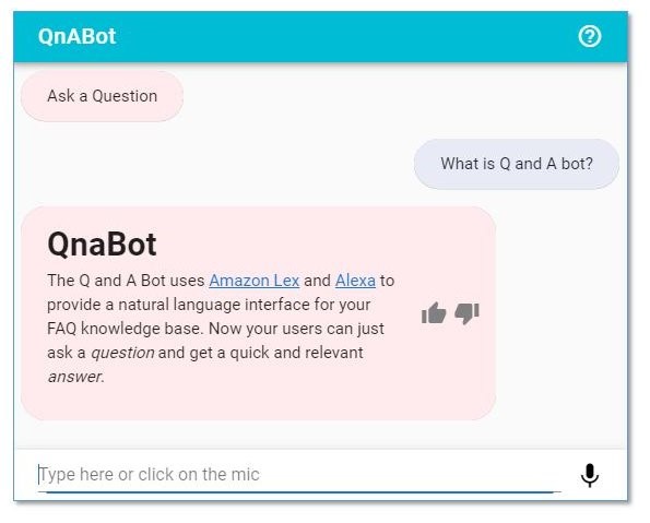
Alexa, what does a QnABot do? This new Solutions Implementation dives deep on AWS QnABot, a multi-channel, multi-language conversational interface (chatbot) that responds to customer’s questions, answers, and feedback. Learn how to deploy QnABot across channels such as chat, voice, SMS, and Amazon Alexa, implementing the newest ML technologies to enhance the customer experience and build more efficient communications.

Use the web user interface to ask: “What is Q and A bot?”. The answer now displays the heading, links, and emphasis specified in your markdown text.

Exploring Data Transfer Costs for AWS Managed Databases

Post Syndicated from Dennis Schmidt original https://aws.amazon.com/blogs/architecture/exploring-data-transfer-costs-for-aws-managed-databases/

When selecting managed database services in AWS, it’s important to understand how data transfer charges are calculated – whether it’s relational, key-value, document, in-memory, graph, time series, wide column, or ledger.

This blog will outline the data transfer charges for several AWS managed database offerings to help you choose the most cost-effective setup for your workload.

This blog illustrates pricing at the time of publication and assumes no volume discounts or applicable taxes and duties. For demonstration purposes, we list the primary AWS Region as US East (Northern Virginia) and the secondary Region is US West (Oregon). Always refer to the individual service pricing pages for the most up-to-date pricing.

Data transfer between AWS and internet

There is no charge for inbound data transfer across all services in all Regions. When you transfer data from AWS resources to the internet, you’re charged per service, with rates specific to the originating Region. Figure 1 illustrates data transfer charges that accrue from AWS services discussed in this blog out to the public internet in the US East (Northern Virginia) Region.

Data transfer to the internet

Figure 1. Data transfer to the internet

The remainder of this blog will focus on data transfer within AWS.

Data transfer with Amazon RDS

Amazon Relational Database Service (Amazon RDS) makes it straightforward to set up, operate, and scale a relational database in the cloud. Amazon RDS provides six database engines to choose from: Amazon Aurora, MySQL, MariaDB, Oracle, SQL Server, and PostgreSQL.

Let’s consider an application running on Amazon Elastic Compute Cloud (Amazon EC2) that uses Amazon RDS as a data store.

Figure 2 illustrates where data transfer charges apply. For clarity, we have left out connection points to the replica servers – this is addressed in Figure 3.

Amazon RDS data transfer

Figure 2. Amazon RDS data transfer

In this setup, you will not incur charges for:

  • Data transfer to or from Amazon EC2 in the same Region, Availability Zone, and virtual private cloud (VPC)

You will accrue charges for data transfer between:

  • Amazon EC2 and Amazon RDS across Availability Zones within the same VPC, charged at Amazon EC2 and Amazon RDS ($0.01/GB in and $0.01/GB out)
  • Amazon EC2 and Amazon RDS across Availability Zones and across VPCs, charged at Amazon EC2 only ($0.01/GB in and $0.01/GB out). For Aurora, this is charged at Amazon EC2 and Aurora ($0.01/GB in and $0.01/GB out)
  • Amazon EC2 and Amazon RDS across Regions, charged on both sides of the transfer ($0.02/GB out)

Figure 3 illustrates several features that are available within Amazon RDS to show where data transfer charges apply. These include multi-Availability Zone deployment, read replicas, and cross-Region automated backups. Not all database engines support all features, consult the product documentation to learn more.

Amazon RDS features

Figure 3. Amazon RDS features

In this setup, you will not incur data transfer charges for:

In addition to the charges you will incur when you transfer data to the internet, you will accrue data transfer charges for:

  • Data replication to read replicas deployed across Regions ($0.02/GB out)
  • Regional transfers for Amazon RDS snapshot copies or automated cross-Region backups ($0.02/GB out)

Refer to the following pricing pages for more detail:

Data transfer with Amazon DynamoDB

Amazon DynamoDB is a key-value and document database that delivers single-digit millisecond performance at any scale. Figures 4 and 5 illustrate an application hosted on Amazon EC2 that uses DynamoDB as a data store and includes DynamoDB global tables and DynamoDB Accelerator (DAX).

DynamoDB with global tables

Figure 4. DynamoDB with global tables

DynamoDB without global tables

Figure 5. DynamoDB without global tables

You will not incur data transfer charges for:

  • Inbound data transfer to DynamoDB
  • Data transfer between DynamoDB and Amazon EC2 in the same Region
  • Data transfer between Amazon EC2 and DAX in the same Availability Zone

In addition to the charges you will incur when you transfer data to the internet, you will accrue charges for data transfer between:

  • Amazon EC2 and DAX across Availability Zones, charged at the EC2 instance ($0.01/GB in and $0.01/GB out)
  • Global tables for cross-Region replication or adding replicas to tables that contain data in DynamoDB, charged at the source Region, as shown in Figure 4 ($0.02/GB out)
  • Amazon EC2 and DynamoDB across Regions, charged on both sides of the transfer, as shown in Figure 5 ($0.02/GB out)

Refer to the DynamoDB pricing page for more detail.

Data transfer with Amazon Redshift

Amazon Redshift is a cloud data warehouse that makes it fast and cost-effective to analyze your data using standard SQL and your existing business intelligence tools. There are many integrations and services available to query and visualize data within Amazon Redshift. To illustrate data transfer costs, Figure 6 shows an EC2 instance running a consumer application connecting to Amazon Redshift over JDBC/ODBC.

Amazon Redshift data transfer

Figure 6. Amazon Redshift data transfer

You will not incur data transfer charges for:

  • Data transfer within the same Availability Zone
  • Data transfer to Amazon S3 for backup, restore, load, and unload operations in the same Region

In addition to the charges you will incur when you transfer data to the internet, you will accrue charges for the following:

  • Across Availability Zones, charged on both sides of the transfer ($0.01/GB in and $0.01/GB out)
  • Across Regions, charged on both sides of the transfer ($0.02/GB out)

Refer to the Amazon Redshift pricing page for more detail.

Data transfer with Amazon DocumentDB

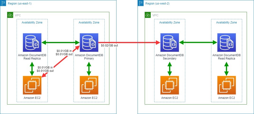
Amazon DocumentDB (with MongoDB compatibility) is a database service that is purpose-built for JSON data management at scale. Figure 7 illustrates an application hosted on Amazon EC2 that uses Amazon DocumentDB as a data store, with read replicas in multiple Availability Zones and cross-Region replication for Amazon DocumentDB Global Clusters.

Amazon DocumentDB data transfer

Figure 7. Amazon DocumentDB data transfer

You will not incur data transfer charges for:

  • Data transfer between Amazon DocumentDB and EC2 instances in the same Availability Zone
  • Data transferred for replicating multi-Availability Zone deployments of Amazon DocumentDB between Availability Zones in the same Region

In addition to the charges you will incur when you transfer data to the internet, you will accrue charges for the following:

  • Between Amazon EC2 and Amazon DocumentDB in different Availability Zones within a Region, charged at Amazon EC2 and Amazon DocumentDB ($0.01/GB in and $0.01/GB out)
  • Across Regions between Amazon DocumentDB instances, charged at the source Region ($0.02/GB out)

Refer to the Amazon DocumentDB pricing page for more details.

Tips to save on data transfer costs to your databases

  • Review potential data transfer charges on both sides of your communication channel. Remember that “Data Transfer In” to a destination is also “Data Transfer Out” from a source.
  • Use Regional and global readers or replicas where available. This can reduce the amount of cross-Availability Zone or cross-Region traffic.
  • Consider data transfer tiered pricing when estimating workload pricing. Rate tiers aggregate usage for data transferred out to the Internet across Amazon EC2, Amazon RDS, Amazon Redshift, DynamoDB, Amazon S3, and several other services. See the Amazon EC2 On-Demand pricing page for more details.
  • Understand backup or snapshots requirements and how data transfer charges apply.
  • AWS offers various purpose-built, managed database offerings. Selecting the right one for your workload can optimize performance and cost.
  • Review your application and query design. Look for ways to reduce the amount of data transferred between your application and data store. Consider designing your application or queries to use read replicas.

Conclusion/next steps

AWS offers purpose-built databases to support your applications and data models, including relational, key-value, document, in-memory, graph, time series, wide column, and ledger databases. Each database has different deployment options, and understanding different data transfer charges can help you design a cost-efficient architecture.

This blog post is intended to help you make informed decisions for designing your workload using managed databases in AWS. Note that service charges and charges related to network topology, such as AWS Transit Gateway, VPC Peering, and AWS Direct Connect, are out of scope for this blog but should be carefully considered when designing any architecture.

Looking for more cost saving tips and information? Check out the Overview of Data Transfer Costs for Common Architectures blog post.

Field Notes: Extending the Baseline in AWS Control Tower to Accelerate the Transition from AWS Landing Zone

Post Syndicated from MinWoo Lee original https://aws.amazon.com/blogs/architecture/field-notes-extending-the-baseline-in-aws-control-tower-to-accelerate-the-transition-from-aws-landing-zone/

Customers who adopt and operate the AWS Landing Zone solution as a scalable multi-account environment are starting to migrate to the AWS Control Tower service. They are doing so to enjoy the added benefits of managed services such as stability, feature enhancement, and operational efficiency. Customers who fully use the baseline for governance control provided by AWS Landing Zone for their member accounts may want to apply the baseline of the same feature without omission even when transitioning to AWS Control Tower. To baseline an account is to set up common blueprints and guardrails required for an organization to enable governance at the start of the account.

As shown in Table 1, AWS Control Tower provides most of the features that are mapped with the baseline of the AWS Landing Zone solution through the baseline stacks, guardrails, and account factory, but some features are unique to AWS Landing Zone.

Table 1. AWS Landing Zone and
AWS Control Tower Baseline mapping
AWS Landing Zone baseline stack AWS Control Tower baseline stack
AWS-Landing-Zone-Baseline-EnableCloudTrail AWSControlTowerBP-BASELINE-CLOUDTRAIL
AWS-Landing-Zone-Baseline-SecurityRoles AWSControlTowerBP-BASELINE-ROLES
AWS-Landing-Zone-Baseline-EnableConfig AWSControlTowerBP-BASELINE-CLOUDWATCH
AWSControlTowerBP-BASELINE-CONFIG
AWSControlTowerBP-BASELINE-SERVICE-ROLES
AWS-Landing-Zone-Baseline-ConfigRole AWSControlTowerBP-BASELINE-SERVICE-ROLES
AWS-Landing-Zone-Baseline-EnableConfigRule Guardrails – Enable guardrail on OU
(AWSControlTowerGuardrailAWS-GR-xxxxx)
AWS-Landing-Zone-Baseline-EnableConfigRulesGlobal Guardrails – Enable guardrail on OU
(AWSControlTowerGuardrailAWS-GR-xxxxx)
AWS-Landing-Zone-Baseline-PrimaryVPC Account Factory – Network Configuration
AWS-Landing-Zone-Baseline-IamPasswordPolicy
AWS-Landing-Zone-Baseline-EnableNotifications

The baselines uniquely provided by AWS Landing Zone are as follows:

  • AWS-Landing-Zone-Baseline-IamPasswordPolicy
    • AWS Lambda to configure AWS Identity and Access Management (IAM) custom password policy (such as minimum password length, password expires period, password complexity, and password history in member accounts).
  • AWS-Landing-Zone-Baseline-EnableNotifications
    • Amazon CloudWatch alarms deliver CloudTrail application programming interface (API) activity such as Security Group changes, Network ACL changes, and Amazon Elastic Compute Cloud (Amazon EC2) instance type changes to the security administrator.

AWS provides the AWS Control Tower lifecycle events and Customizations for AWS Control Tower as a way to add features that are not included by default in AWS Control Tower. Customizations for AWS Control Tower is an AWS solution that allows you to easily add customizations using AWS CloudFormation templates and service control polices.

This blog post explains how to modify and deploy the code to apply AWS Landing Zone specific baselines such as IamPasswordPolicy and EnableNotifications into AWS Control Tower using Customizations for the AWS Control Tower.

Overview of solution

Adhering to the package folder structure of Customizations for AWS Control Tower, modify the AWS Landing Zone IamPasswordPolicy, EnableNotifications template, parameter file, and manifest file to match the AWS Control Tower deployment environment.

When the modified package is uploaded to the source repository, contents of the package are validated and built by launching AWS CodePipeline. The AWS Landing Zone specific baseline is deployed in member accounts through AWS CloudFormation StackSets in the AWS Control Tower management account.

When a new or existing account is enrolled in AWS Control Tower, the same AWS Landing Zone specific baseline is automatically applied to that account by the lifecycle event (CreateManagedAccount status is SUCCEEDED).

Figure 1 shows how the default baseline of AWS Control Tower and the specific baseline of AWS Landing Zone are applied to member accounts.

Figure 1. Default and custom baseline deployment in AWS Control Tower

Figure 1. Default and custom baseline deployment in AWS Control Tower

Walkthrough

This solution follows these steps:

  1. Download and extract the latest version of the AWS Landing Zone Configuration source package. The package contains several functional components including baseline of IamPasswordPolicy, EnableNotifications for applying to accounts in AWS Landing Zone environment. If you are transitioning from AWS Landing Zone to AWS Control Tower, you may use the AWS Landing Zone configuration source package that exists in your management account.
  2. Download and extract the configuration source package of your Customizations for AWS Control Tower.
  3. Create templates and parameters folder structure for customizing configuration package source of Customizations for AWS Control Tower.
  4.  Copy the template and parameter files of the IamPasswordPolicy baseline from the AWS Landing Zone configuration source to the Customizations for AWS Control Tower configuration source.
    1. Open the parameter file (JSON), and modify the parameter value to match your organization’s password policy.
  1. Copy the template and parameter files of the EnableNotifications baseline from the AWS Landing Zone configuration source to the Customizations for AWS Control Tower configuration source.
    1. Open the parameter file (JSON), and change the LogGroupName parameter value to the CloudWatch log group name of your AWS Control Tower environment. Select whether or not to use each alarm in the parameter value.
    2. Open the template file (YAML), and modify the AlarmActions properties of all CloudWatch alarms to refer to the security topic of the Amazon Simple Notification Service (Amazon SNS) that exists in your AWS Control Tower environment.
  1. Open the manifest (YAML) file in the configuration source of Customizations for AWS Control Tower, and update with the modified IamPasswordPolicy and EnableNotifications parameter, template file path, and organizational unit to be applied.
    1. If you have customizations which have already been deployed and operated through Customizations for AWS Control Tower, do not remove existing contents, and consecutively add customized resource in resources section.
  1. Compress the completed source package, and upload it to the source repository of Customizations for AWS Control Tower.
  2. Check the results for applying this solution in AWS Control Tower.
    1. In the management account, wait for all AWS CodePipeline steps in Customizations for AWS Control Tower to be completed.
    2. In the management account, check that the CloudFormation IamPasswordPolicy and EnableNotifications StackSet is deployed.
    3. In a member account, check that the custom password policy is configured in Account Settings of IAM.
    4. In a member account, check that alarms are created in All Alarms of CloudWatch.

Prerequisites

For this walkthrough, you should have the following prerequisites:

  • AWS Control Tower deployment.
  • An AWS Control Tower member account.
  • Customizations for AWS Control Tower solution deployment.
  • IAM user and roles, and permission to allow use of ‘CustomControlTowerKMSKey’ in AWS Key Management Service Key Policy to access Amazon Simple Storage Service (Amazon S3) as the configuration source.
    • This is not required in case of using CodeCommit as source repository, but it assumes that Amazon S3 is used for this solution.
  • If the IamPasswordPolicy and EnableNotifications baseline for the AWS Landing Zone service has been deployed in the AWS Control Tower environment, it is necessary to delete stack instances and StackSet associated with the following CloudFormation StackSets:
    • AWS-Landing-Zone-Baseline-IamPasswordPolicy
    • AWS-Landing-Zone-Baseline-EnableNotifications
  • An IAM or AWS Single Sign-On (AWS SSO) account with the following settings:
    • Permission with AdministratorAccess
    • Access type with Programmatic access and AWS Management Console access
  • AWS Command Line Interface (AWS CLI) and Linux Zip package installation in work environment.
  • An IAM or AWS SSO user for member account (optional).

Prepare the work environment

Download the AWS Landing Zone configuration package and Customizations for AWS Control Tower configuration package, and create a folder structure.

  1. Open your terminal AWS Command Line Interface (AWS CLI).

Note: Confirm that AWS Config and credentials for the AWS Command Line Interface (AWS CLI) are properly set as access method (IAM or AWS SSO user) you are using in management account.

  1. Change to home directory and download the aws-landing-zone-configuration.zip file.
cd ~
wget https://s3.amazonaws.com/solutions-reference/aws-landing-zone/latest/aws-landing-zone-configuration.zip
  1.  Extract AWS Landing Zone configuration file to new directory (Named alz).
unzip aws-landing-zone-configuration.zip -d ~/alz
  1. Download _custom-control-tower-configuration.zip file in Customizations for AWS Control Tower configuration’s S3 bucket. Use your AWS Account Id and home Region in S3 bucket name.

Note: If you have already used the Customizations for AWS Control Tower configuration package, or have the Auto Build parameter set to true, use custom-control-tower-configuration.zip instead of _custom-control-tower-configuration.zip.

aws s3 cp s3://custom-control-tower-configuration-<AWS Account Id >-<AWS Region>/_custom-control-tower-configuration.zip ~/

Figure 2. Downloading source package of Customizations for AWS Control Tower

  1. Extract Customizations for AWS Control Tower configuration file to new directory (Named cfct).
unzip _custom-control-tower-configuration.zip -d ~/cfct
  1. Create templates and parameters directory under Customizations for AWS Control Tower configuration directory.
cd ~/cfct
mkdir templates parameters

Now you will see directories and files under Customizations for AWS Control Tower configuration directory.

Note: example-configuration is just an example, and will not be used in this blog post.

 Figure 3. Directory structure of Customizations for AWS Control Tower

Figure 3. Directory structure of Customizations for AWS Control Tower

Customize to include AWS Landing Zone specific baseline

Start customization work by integrating the AWS Landing Zone IamPasswordPolicy and EnableNotifications baseline related files into the structure of Customizations for AWS Control Tower configuration package.

  1. Copy the IamPasswordPolicy baseline template and parameter file into the Customizations for AWS Control Tower configuration directory.
cp ~/alz/templates/aws_baseline/aws-landing-zone-iam-password-policy.template ~/cfct/templates/
cp ~/alz/parameters/aws_baseline/aws-landing-zone-iam-password-policy.json ~/cfct/parameters/
  1. Open the copied aws-landing-zone-iam-password-policy.json, then adjust it to be compliant with your optional password policy requirement.
  2. Copy the EnableNotifications baseline template and parameter file into the Customizations for AWS Control Tower configuration directory.
cp ~/alz/templates/aws_baseline/aws-landing-zone-notifications.template ~/cfct/templates/
cp ~/alz/parameters/aws_baseline/aws-landing-zone-notifications.json ~/cfct/parameters/
  1. Open the copied aws-landing-zone-notifications.template.

Remove the following four lines from the SNSNotificationTopic parameter:

SNSNotificationTopic:
    Type: AWS::SSM::Parameter::Value<String>
    Default: /org/member/local_sns_arn
    Description: "Local Admin SNS Topic for Landing Zone"

Modify AlarmActions under Properties for each of 11 CloudWatch alarms as follows:

AlarmActions:
      - !Sub 'arn:aws:sns:${AWS::Region}:${AWS::AccountId}:aws-controltower-SecurityNotifications'
  1. Open aws-landing-zone-notifications.json.

Remove the following five lines from the SNSNotificationTopic parameter key, and parameter value at the bottom of file. Make sure to remove the including comma preceding the JSON syntax.

  ,
  {
    "ParameterKey": "SNSNotificationTopic",
    "ParameterValue": "/org/member/local_sns_arn"
  }

     Modify the parameter value of LogGroupName parameter key as follows:

{
"ParameterKey": "LogGroupName",
"ParameterValue": "aws-controltower/CloudTrailLogs"
},

6. Open the manifest.yaml under root of the Customizations for AWS Control Tower configuration directory, then modify it to include IamPasswordPolicy and EnableNotifications baseline. If there are customizations that  have been previously used in the manifest file of Customizations for AWS Control Tower, add them at the end.

7. Properly adjust region, resource_file, parameter_file, and organizational_units for your AWS Control Tower environment.

Note: Choose the proper organizational units because Customizations for AWS Control Tower will try to deploy customization resources to all AWS accounts within operational units defined in organizational_units property. If you want to select specific accounts, consider using accounts property instead of organizational_units property.

Review the following sample manifest file:

---
#Default region for deploying Custom Control Tower: Code Pipeline, Step functions, Lambda, SSM parameters, and StackSets
region: ap-northeast-2
version: 2021-03-15

# Control Tower Custom Resources (Service Control Policies or CloudFormation)
resources:
  - name: IamPasswordPolicy
    resource_file: templates/aws-landing-zone-iam-password-policy.template
    parameter_file: parameters/aws-landing-zone-iam-password-policy.json
    deploy_method: stack_set
    deployment_targets:
      organizational_units:
        - Security
        - Infrastructure
        - app-services
        - app-reports

  - name: EnableNotifications
    resource_file: templates/aws-landing-zone-notifications.template
    parameter_file: parameters/aws-landing-zone-notifications.json
    deploy_method: stack_set
    deployment_targets:
      organizational_units:
        - Security
        - Infrastructure
        - app-services
        - app-reports
  1. Compress all files within the root of the Customizations for AWS Control Tower configuration directory into the custom-control-tower-configuration.zip file.
cd ~/cfct/
zip -r custom-control-tower-configuration.zip ./
  1. Upload the custom-control-tower-configuration.zip file into the Customizations for AWS Control Tower configuration S3 bucket. Use your AWS Account Id and Home Region in the S3 bucket name.
aws s3 cp ~/cfct/custom-control-tower-configuration.zip s3://custom-control-tower-configuration-<AWS Account Id>-<AWS Region>/

Figure 4. Uploading source package of Customizations for AWS Control Tower

Verify solution

Now, you can verify the results for applying this solution.

  1. Log in to your AWS Control Tower management account.
  2.  Navigate to AWS CodePipeline service, then select Custom-Control-Tower-CodePipeline.
  3. Wait for all pipeline stages to complete.
  4. Go to AWS CloudFormation, then choose StackSets.
  5.  Search with the keyword custom. This will result in two custom StackSets.

Figure 5. Custom StackSet of Customizations for AWS Control Tower

  1. Log in to your AWS Control Tower member account.

Note: You need an IAM or AWS SSO user, or simply switch the role to AWSControlTowerExecution in the member account.

  1. Go to IAM, then choose Account settings. You will see a configured custom password policy.
Figure 6. IAM custom password policy of member account

Figure 6. IAM custom password policy of member account

  1. Go to Amazon CloudWatch, then choose All alarms. You will see 11 configured alarms.

Figure 7. Amazon CloudWatch alarms of member account

Cleaning up

Resources deployed to member accounts by this solution can be removed through the CloudFormation Stack function in the management account.

Run Delete stack from StackSet, followed by Delete StackSet, for the following two StackSets.

  • CustomControlTower-IamPasswordPolicy
  • CustomControlTower-EnableNotifications

Conclusion

In this blog post, you learned how to extend the baseline in AWS Control Tower to include the baseline specific to AWS Landing Zone. The principal idea is to use Customizations for AWS Control Tower, and additionally add guardrails, such as AWS Config rule and service control policy, which are not included by default in AWS Control Tower. This helps the transition of AWS Landing Zone to the AWS Control Tower, and enhances the governance control capability of the enterprise.

Related reading: Seamless Transition from an AWS Landing Zone to AWS Control Tower

Field Notes provides hands-on technical guidance from AWS Solutions Architects, consultants, and technical account managers, based on their experiences in the field solving real-world business problems for customers.

Field Notes: Analyze Cross-Account AWS KMS Call Usage with AWS CloudTrail and Amazon Athena

Post Syndicated from Abhijit Rajeshirke original https://aws.amazon.com/blogs/architecture/field-notes-analyze-cross-account-aws-kms-call-usage-with-aws-cloudtrail-and-amazon-athena/

Businesses are expanding their footprint on Amazon Web Services (AWS) and are adopting a multi-account strategy to help isolate and manage business applications and data. In the multi-account strategy, it is common to have business applications deployed in one account accessing an Amazon Simple Storage Service (Amazon S3) encrypted bucket from another AWS account.

When an application in an AWS account uses a AWS Key Management Service (AWS KMS) key owned by a different account, it’s known as a cross-account call. For cross-account requests, AWS KMS throttles the account that makes the requests, not the account that owns the AWS KMS key. These requests count toward the request quota of the caller account. Sometimes it’s essential to identify or track cross-account AWS KMS API usage. In this blog, you will learn about use cases to track these requests and steps to identify cross-account AWS KMS calls.

To understand the problem better, consider a scenario where you have multiple AWS accounts set up in a hub and spoke configuration as shown in the following diagram.  Each account is administered by a different administrator. Amazon S3 data lake is located in the centralized hub account. The data lake bucket is encrypted using server-side encryption with AWS KMS (SSE-KMS) with customer-managed keys. Multiple spoke accounts access datasets from this data lake bucket. When a spoke account uploads or downloads objects from the data lake, Amazon S3 makes a GenerateDataKey (for uploads) or Decrypt (for downloads) API request to AWS KMS on behalf of the spoke account. These API requests get applied toward AWS KMS quota of the spoke account.

In the following diagram (figure 1), spoke accounts B, C, and D are uploading/downloading files from the encrypted data lake located in hub account A. Related AWS KMS API quotas will get applied to spoke accounts even though encryption/decryption is happening at the data lake S3 bucket. For example, the centralized Amazon S3 data lake is located in hub account A with an account ID 111111111111. Amazon S3 data lake bucket is encrypted using AWS KMS key ARN ending in 3aa3c82a2174.

Spoke account B with account ID 222222222222 is downloading 1,811 files and uploading 749 files from the centralized data lake. A total of 2,560 AWS KMS API calls will be counted against the request quota for account B.

Spoke account C with account ID 33333333333 is downloading 997 files and uploading 271 files from centralized data lake. A total of 1,268 AWS KMS API calls will be counted against the request quota for account C.

Spoke account D with account ID 444444444444 is downloading 638 files and uploading 306 files from centralized data lake from centralized data lake. The total 944 AWS KMS API quotas will get applied to account D.

Spoke and hub accounts are owned by separate business units and owned by different account administrators.

Note: when you configure your bucket to use an S3 Bucket Key for SSE-KMS, you may not see separate Decrypt or GenerateDataKey for each file upload or download.

Figure 1: Architecture outlining the hub and spoke accounts

Figure 1: Architecture outlining the hub and spoke accounts

This architecture design works for the following three use cases.

Use case #1:

A spoke account administrator wants to track the individual AWS KMS key-wise encryption/decryption costs using AWS Cost Explorer and cost allocation tags. Tracking costs this way works well for the AWS KMS API calls made within the same spoke account and related costs will be displayed under appropriate cost allocation tags. However, for the cross account AWS KMS API calls, cost allocation tags will not be visible outside of the hub account and will be displayed under cost allocation tag “None.” Analyzing cross-account AWS KMS API calls will help administrator determine approximate percentage usage by each cross account KMS key.

Use case # 2:

The spoke account has multiple applications, and each application has a unique AWS Identity and Access Management (IAM) principal. The spoke account administrator would like to track encryption/decryption usage. Identifying IAM principal-wise cross account calls will help the administrator determine approximate percent usage by each IAM principal /each application.

Use case # 3:

The spoke account administrator wants to understand how much AWS KMS quota is used for the cross-account specific KMS keys.

Solution Overview

Let’s discuss how we can track cross-account AWS KMS calls using AWS CloudTrail and Amazon Athena. For this solution, we will reuse your existing CloudTrail or create new CloudTrail in a Region where the hub account Amazon S3 data lake is located. As shown in the following diagram, we will use Athena to query the CloudTrail data to identify cross account AWS KMS calls used for S3 encryption/decryption.

Figure 2- Spoke and hub architecture

Figure 2: Architecture outlining the CloudTrail and Athena Solution

Prerequisites

For this walkthrough, you should have the following prerequisites:

  • AWS accounts (one for hub and at least one for spoke)
  • AWS KMS (SSE-KMS) with customer managed keys encrypted S3 bucket

Walkthrough

Step 1: Activate AWS CloudTrail for the hub account

CloudTrail is a service that enables governance, compliance, operational auditing, and risk auditing of your AWS account. With CloudTrail, you can log, continuously monitor, and retain account activity across your AWS accounts. If you have already activated CloudTrail, you can reuse the same. If you haven’t, you can activate it using the steps in this tutorial. For the proposed solution, you must enable CloudTrail for management events only. You don’t require CloudTrail for data events or insight events. Also, be aware that you need only single CloudTrail and creating duplicate cloud trails can increase the service cost.

Note:  you can analyze the data in Athena only when the CloudTrail data is available. Any access requests made prior to enabling CloudTrail cannot be analyzed. It takes up to 15 minutes for events to get to CloudTrail, and up to 5 minutes for CloudTrail to write to S3.

Step 2: Create Amazon Athena table to query the CloudTrail data

Amazon Athena is an interactive query service that analyzes data in Amazon S3 using standard SQL. Athena is serverless, so there is no infrastructure to manage, and you pay only for the queries that you run. Create an Athena table in any database or default database in a Region where your hub account S3 data lake bucket resides.

If you are using Athena for the first time, follow these steps to create a database. Once the database is created you need to create Athena table. Follow these steps to create a table:

  1. Open the Athena built-in query editor,
  2. copy the following query,
  3. modify as suggested,
  4. run the query.

In the LOCATION and storage.location.template clauses, replace the bucket with CloudTrail bucket. Replace accountId with hub account’s ID and replace awsRegion with region where data lake S3 bucket is located. For projection.timestamp.range, replace 2020/01/01 with the start date you want to use.

After successful initiation of the query, you will see the CloudTrail_logs table created in Athena.

CREATE EXTERNAL TABLE cloudtrail_logs_region(

    eventVersion STRING,

    userIdentity STRUCT<

        type: STRING,

        principalId: STRING,

        arn: STRING,

        accountId: STRING,

        invokedBy: STRING,

        accessKeyId: STRING,

        userName: STRING,

        sessionContext: STRUCT<

            attributes: STRUCT<

                mfaAuthenticated: STRING,

                creationDate: STRING>,

            sessionIssuer: STRUCT<

                type: STRING,

                principalId: STRING,

                arn: STRING,

                accountId: STRING,

                userName: STRING>>>,

    eventTime STRING,

    eventSource STRING,

    eventName STRING,

    awsRegion STRING,

    sourceIpAddress STRING,

    userAgent STRING,

    errorCode STRING,

    errorMessage STRING,

    requestParameters STRING,

    responseElements STRING,

    additionalEventData STRING,

    requestId STRING,

    eventId STRING,

    readOnly STRING,

    resources ARRAY<STRUCT<

        arn: STRING,

        accountId: STRING,

        type: STRING>>,

    eventType STRING,

    apiVersion STRING,

    recipientAccountId STRING,

    serviceEventDetails STRING,

    sharedEventID STRING,

    vpcEndpointId STRING

  )

PARTITIONED BY (

   `timestamp` string)

ROW FORMAT SERDE 'com.amazon.emr.hive.serde.CloudTrailSerde'

STORED AS INPUTFORMAT 'com.amazon.emr.cloudtrail.CloudTrailInputFormat'

OUTPUTFORMAT 'org.apache.hadoop.hive.ql.io.HiveIgnoreKeyTextOutputFormat'

LOCATION

  's3://bucket/AWSLogs/account-id/CloudTrail/aws-region'

TBLPROPERTIES (

  'projection.enabled'='true',

  'projection.timestamp.format'='yyyy/MM/dd',

  'projection.timestamp.interval'='1',

  'projection.timestamp.interval.unit'='DAYS',

  'projection.timestamp.range'='2020/01/01,NOW',

  'projection.timestamp.type'='date',

  'storage.location.template'='s3://bucket/AWSLogs/account-id/CloudTrail/aws-region/${timestamp}')

Athena screenshot

Step 3: Identify cross account Amazon S3 encryption/decryption calls

Once the Athena table is created, you can run the following query to find out cross-account AWS KMS calls made for S3 encryption /decryption.

Query:

SELECT useridentity.accountid as requestor_account_id,

              resources[1].accountid as owner_account_id,

              resources[1].arn as key_arn,       

          count(resources) as count

  FROM CloudTrail_logs_us_east_2

  WHERE eventsource='kms.amazonaws.com'

          AND timestamp between '2021/04/01' and '2021/08/30'

          AND eventname in ('Decrypt','Encrypt','GenerateDataKey')

          AND useridentity.accountid!= resources[1].accountid

    AND json_extract(json_extract(requestparameters , '$.encryptionContext'),'$.aws:s3:arn') is not null

  GROUP BY  useridentity.accountid,resources[1].accountid,resources[1].arn

  ORDER BY  key_arn,count desc

Result:

Result displays the cross account AWS KMS calls made for S3 encryption /decryption i.e. where caller account is not the key owner account for time period between April 1, 2021 and August 30, 2021.

Athena screenshot 2

The preceding example shows cross-account AWS KMS API calls generated by downloading /uploading files from centralized Amazon S3 data lake located in account A (111111111111) from spoke accounts B (222222222222), C (333333333333), and D (444444444444).

These AWS KMS quotas will get applied to caller (spoke) accounts even though key owner is hub account.

For example:

  • 2,560 AWS KMS API call quotas will be applied to account B.
  • 1,644 AWS KMS API call quotas will be applied to account C.
  • 944 AWS KMS API call quotas will be applied to account D.

Step 4: Identify IAM principal-wise cross account Amazon S3 encryption/decryption calls.

To identify IAM principal-wise cross account Amazon S3 encryption /decryption calls, you can run following query.

Query:

SELECT useridentity.accountid as requestor_account_id,
useridentity.principalid as requestor_principal,
resources[1].accountid as owner_account_id,
resources[1].arn as key_arn,
count(resources) as count
FROM CloudTrail_logs_us_east_2
WHERE eventsource='kms.amazonaws.com'
AND timestamp between '2021/04/01' and '2021/08/30'
AND eventname in ('Decrypt','Encrypt','GenerateDataKey')
AND useridentity.accountid!= resources[1].accountid
AND json_extract(json_extract(requestparameters , '$.encryptionContext'),'$.aws:s3:arn') is not null
GROUP BY useridentity.accountid,useridentity.principalid,resources[1].accountid,resources[1].arn
ORDER BY requestor_account_id,count desc

Result:

Athena screenshot 3

The preceding result shows  AWS Identity and Access Management (IAM) principal-wise cross-account AWS KMS API calls made between hub and spoke accounts. For example, Account B (22222222222) has two applications configured with IAM principals ids ending with 4C5VIMGI2, 4YFPRTQMP are accessing the centralized S3 bucket located in hub account A (111111111111).

For the time period between ‘2021/04/01’ and ‘2021/08/30’, the application configured with IAM principal ending in 4C5VIMGI2 made 1622 cross-account AWS KMS API calls. During this same time period, the application configured with IAM principal 4YFPRTQMP made 936 cross-account AWS KMS API calls.

We can further filter the results to see only KMS key ARN ending with 3aa3c82a2174 to get application- wise % of AWS KMS API calls made to the Amazon S3 centralized data lake from all the spoke accounts.

account ID table

Note:  we assume that each application is configured with a unique IAM principal.

Step 5: Identify cross account Amazon S3 encryption/decryption calls by events.

Query:

SELECT useridentity.accountid as requestor_account_id,

              resources[1].accountid as owner_account_id,

              resources[1].arn as key_arn,

              eventname as eventname,

          count(resources) as count

  FROM CloudTrail_logs_us_east_2

  WHERE eventsource='kms.amazonaws.com'

          AND timestamp between '2021/04/01' and '2021/08/30'

          AND useridentity.accountid!= resources[1].accountid

        AND json_extract(json_extract(requestparameters , '$.encryptionContext'),'$.aws:s3:arn') is not null

  GROUP BY useridentity.accountid, resources [1].accountid,resources[1].arn,eventname

  ORDER BY requestor_account_id,count desc

Result:

Athena screenshot 4

Amazon S3 makes decrypt API requests when you download the files and GenerateDataKey API request when you upload the file to encrypted S3 bucket. The result shows that:

  • Spoke account B (22222222222) made 1811 decrypt API requests to download 1811 files and 749 GenerateDataKey API requests to uploaded 749 files.
  • Spoke account C (33333333333) made 1373 decrypt API requests to download 1373 files and 271 GenerateDataKey API requests to uploaded 271 files.
  • Spoke account D (444444444444) made 638 decrypt API requests to download 638 files and 306 GenerateDataKey API requests to uploaded 306 files.

Note: When you configure your bucket to use an S3BucketKey for SSE-KMS, you may not have a separate Decrypt or GenerateDataKey for each file upload or download.

Step 6: Identify all the AWS KMS Calls.

To analyze the hub account for all the AWS KMS API calls made, run following query.

Query:

SELECT useridentity.accountid as requestor_account_id,

              resources[1].accountid as owner_account_id,

              resources[1].arn as key_arn,

          count(resources) as count

  FROM CloudTrail_logs_us_east_2

  WHERE eventsource='kms.amazonaws.com'

          AND timestamp between '2021/04/01' and '2021/08/30'

  GROUP BY useridentity.accountid, resources [1].accountid,resources[1].arn

  ORDER BY requestor_account_id,count desc

Result:

Athena screenshot 5

Results show all the AWS KMS API calls made in the hub account both within the account and across accounts. From this result, we can analyze that for centralized S3 data lake (KMS key ARN ending with 3aa3c82a2174), the majority of the calls are cross account AWS KMS API call and only 303 calls are made within account. You can do further analysis by refining the Amazon Athena queries based on your needs.

Cleaning up

To avoid incurring future charges, delete the resources that are no longer required.

Step 1: Delete the CloudTrail created in hub account

If you have created CloudTrail specifically for this solution, you can delete the CloudTrail by following the instructions in this user guide.

Step 2: Drop the Amazon Athena table

Log in to the Amazon Athena console and run the following drop table query:

Drop table < CloudTrail_logs_aws_region_1>

Conclusion

Tracking use of the cross-account AWS KMS APIs can be challenging in a multi-account scenario. In this blog, we learned how to use AWS CloudTrail and Amazon Athena to analyze AWS KMS API usage. In a hub and spoke account model, cross-account AWS KMS API quotas are applied to the spoke account when the spoke account accesses SSE-KMS encrypted S3 bucket in the hub account. You learned to analyze cross-account AWS KMS API quotas using AWS CloudTrail and Amazon Athena.  Finally, we learned how we can identify all the AWS KMS API call within account for period of time and analyze AWS KMS API traffic within account and across account. You can repeat the process and aggregate the data across Regions.

Additional Reading:

Manage your AWS KMS API request rates using Service Quotas and Amazon CloudWatch

Why did my CloudTrail cost and usage increase unexpectedly?

User Guide: Managing CloudTrail Costs

How Parametric Built Audit Surveillance using AWS Data Lake Architecture

Post Syndicated from Raghavarao Sodabathina original https://aws.amazon.com/blogs/architecture/how-parametric-built-audit-surveillance-using-aws-data-lake-architecture/

Parametric Portfolio Associates (Parametric), a wholly owned subsidiary of Morgan Stanley, is a registered investment adviser. Parametric provides investment advisory services to individual and institutional investors around the world. Parametric manages over 100,000 client portfolios with assets under management exceeding $400B (as of 9/30/21).

As a registered investment adviser, Parametric is subject to numerous regulatory requirements. The Parametric Compliance team conducts regular reviews on the firm’s portfolio management activities. To accomplish this, the organization needs both active and archived audit data to be readily available.

Parametric’s on-premises data lake solution was based on an MS-SQL server. They used an Apache Hadoop platform for their data storage, data management, and analytics. Significant gaps existed with the on-premises solution, which complicated audit processes. They were spending a large amount of effort on system maintenance, operational management, and software version upgrades. This required expensive consulting services and challenges with keeping the maintenance windows updated. This limited their agility, and also impacted their ability to derive more insights and value from their data. In an environment of rapid growth, adoption of more sophisticated analytics tools and processes has been slower to evolve.

In this blog post, we will show how Parametric implemented their Audit Surveillance Data Lake on AWS with purpose-built fully managed analytics services. With this solution, Parametric was able to respond to various audit requests within hours rather than days or weeks. This resulted in a system with a cost savings of 5x, with no data growth. Additionally, this new system can seamlessly support a 10x data growth.

Audit surveillance platform

The Parametric data management office (DMO) was previously running their data workloads using an on-premises data lake, which ran on the Hortonworks data platform of Apache Hadoop. This platform wasn’t up to date, and Parametric’s hardware was reaching end-of-life. Parametric was faced with a decision to either reinvest in their on-premises infrastructure or modernize their infrastructure using a modern data analytics platform on AWS. After doing a detailed cost/benefit analysis, the DMO calculated a 5x cost savings by using AWS. They decided to move forward and modernize with AWS due to these cost benefits, in addition to elasticity and security features.

The PPA compliance team asked the DMO to provide an enterprise data service to consume data from a data lake. This data was destined for downstream applications and ad-hoc data querying capabilities. It was accessed via standard JDBC tools and user-friendly business intelligence dashboards. The goal was to ensure that seven years of audit data would be readily available.

The DMO team worked with AWS to conceptualize an audit surveillance data platform architecture and help accelerate the implementation. They attended a series of AWS Immersion Days focusing on AWS fundamentals, Data Lakes, Devops, Amazon EMR, and serverless architectures. They later were involved in a four-day AWS Data Lab with AWS SMEs to create a data lake. The first use case in this Lab was creating the Audit Surveillance system on AWS.

Audit surveillance architecture on AWS

The following diagram shows the Audit Surveillance data lake architecture on AWS by using AWS purpose-built analytics services.

Figure 1. Audit Surveillance data lake architecture diagram

Figure 1. Audit Surveillance data lake architecture diagram

Architecture flow

  1. User personas: As first step, the DMO team identified three user personas for the Audit Surveillance system on AWS.
    • Data service compliance users who would like to consume audit surveillance data from the data lake into their respective applications through an enterprise data service.
    • Business users who would like to create business intelligence dashboards using a BI tool to audit data for compliance needs.
    • Complaince IT users who would like to perform ad-hoc queries on the data lake to perform analytics using an interactive query tool.
  2. Data ingestion: Data is ingested into Amazon Simple Storage Service (S3) from different on-premises data sources by using AWS Lake Formation blueprints. AWS Lake Formation provides workflows that define the data source and schedule to import data into the data lake. It is a container for AWS Glue crawlers, jobs, and triggers that are used to orchestrate the process to load and update the data lake.
  3. Data storage: Parametric used Amazon S3 as a data storage to build an Audit Surveillance data lake, as it has unmatched 11 nines of durability and 99.99% availability. The existing Hadoop storage was replaced with Amazon S3. The DMO team created a drop zone (raw), an analytics zone (transformed), and curated (enriched) storage layers for their data lake on AWS.
  4. Data cataloging: AWS Glue Data Catalog was the central catalog used to store and manage metadata for all datasets hosted in the Audit Surveillance data lake. The existing Hadoop metadata store was replaced with AWS Glue Data Catalog. AWS services such as AWS Glue, Amazon EMR, and Amazon Athena, natively integrate with AWS Glue Data Catalog.
  5. Data processing: Amazon EMR and AWS Glue process the raw data and places it into analytics zones (transformed) and curated zones (enriched) S3 buckets. Amazon EMR was used for big data processing and AWS Glue for standard ETL processes. AWS Lambda and AWS Step Functions were used to initiate monitoring and ETL processes.
  6. Data consumption: After Audit Surveillance data was transformed and enriched, the data was consumed by various personas within the firm as follows:
    • AWS Lambda and Amazon API Gateway were used to support consumption for data service compliance users.
    • Amazon QuickSight was used to create business intelligence dashboards for compliance business users.
    • Amazon Athena was used to query transformed and enriched data for compliance IT users.
  7. Security: AWS Key Management Service (KMS) customer managed keys were used for encryption at rest, and TLS for encryption at transition. Access to the encryption keys is controlled using AWS Identity and Access Management (IAM) and is monitored through detailed audit trails in AWS CloudTrail. Amazon CloudWatch was used for monitoring, and thresholds were created to determine when to send alerts.
  8. Governance: AWS IAM roles were attached to compliance users that permitted the administrator to grant access. This was only given to approved users or programs that went through authentication and authorization through AWS SSO. Access is logged and permissions can be granted or denied by the administrator. AWS Lake Formation is used for fine-grained access controls to grant/revoke permissions at the database, table, or column-level access.

Conclusion

The Parametric DMO team successfully replaced their on-premises Audit Surveillance Data Lake. They now have a modern, flexible, highly available, and scalable data platform on AWS, with purpose-built analytics services.

This change resulted in a 5x cost savings, and provides for a 10x data growth. There are now fast responses to internal and external audit requests (hours rather than days or weeks). This migration has given the company access to a wider breadth of AWS analytics services, which offers greater flexibility and options.

Maintaining the on-premises data lake would have required significant investment in both hardware upgrade costs and annual licensing and upgrade vendor consulting fees. Parametric’s decision to migrate their on-premises data lake has yielded proven cost benefits. And it has introduced new functions, service, and capabilities that were previously unavailable to Parametric DMO.

You may also achieve similar efficiencies and increase scalability by migrating on-premises data platforms into AWS. Read more and get started on building Data Lakes on AWS.

Field Notes: Understanding Carrier Codes, Message Structure, and Interaction Analytics with Amazon Pinpoint

Post Syndicated from Edward Schaefer original https://aws.amazon.com/blogs/architecture/field-notes-understanding-carrier-codes-message-structure-and-interaction-analytics-with-amazon-pinpoint/

IT developers are frequently looking for an analytics system that tracks app user behavior and engagement with various marketing campaigns. It can be challenging to differentiate between use cases and advantages of utilizing Long Codes, Short Codes and Toll-Free numbers to feed into interaction analytics. With Amazon Pinpoint, developers can learn how each user prefers to engage and can personalize their end-user’s experience to increase engagement.

In this blog post, we’ll evaluate the differences between Long Codes, Short Codes and Toll-Free and we’ll also discuss messaging templates and creating journeys to customize events handling in Amazon Pinpoint.

Typical use cases of Amazon Pinpoint include:

  • Sending timely and targeted message to your customers promoting your products and services with basic templates or highly-personalized messages.
  • Event-based campaigns can be used to send a message when a customer creates a new account or when they add an item to their cart but don’t purchase it. These communications are transactional in nature and can be sent on customer activities within your application.
  • You can create customer outreach with millions in user communities and use built-in analytics to observe your campaign performance.

SMS messaging forms one of the most critical communication channels with customers. Both one way and two-way messaging are supported by Amazon Pinpoint when you enable the SMS channel in your project.

Architecture overview

The following diagram illustrates a typical architecture for how Pinpoint integrates with various AWS services.

Architecture outlining how Pinpoint intrgatios with various AWS services.

Long codes, short codes, and toll-free numbers

Dedicated long codes and 10DLC

A dedicated long code, also referred to as a long virtual number or LVN, is a standard phone number that contains up to 12 digits, depending on the country that it’s based in. You cannot request a long code for A2P messaging within the United States. Instead, you’ll need to request a 10DLC.

Typically used for customer service-related communications, long codes also allow businesses to establish consistent experiences. This is done by using the same number to send both SMS text messages as well as voice messages to customers.

In the United States, 10-digit long code (10DLC) numbers are designed specifically for high-volume Application-to-Person (A2P) messaging. Before purchasing a 10DLC, you must first register your company and create a campaign using the Amazon Pinpoint console. Since Jun 1, 2021, United States mobile carriers require 10DLC for A2P messages.

Common use cases: Customer service, appointment reminders, two-way communications, fraud, or emergency notifications (10DLC), promotional messaging (10DLC).

Advantages:

  • Customer Trust and Brand recognition: 10DLC and dedicated long codes are registered and dedicated to individual companies and campaigns. This means that if you send multiple messages to a recipient each message will appear to come from the same number.
  • SMS and Voice capable: Businesses can use the same long code numbers for both SMS and voice communications to provide consistent contact experiences to their customers.
  • High reliability and delivery rate (10DLC): 10DLC has been adopted by United States wireless carriers specifically for business messaging. By requiring a registration and pre-vetting process, wireless carriers can support higher message volumes and better deliverability while protecting consumers from potential abuse.
  • Low costs: 10DLC and dedicated long code numbers cost less than dedicate short codes.
  • Fast provisioning: Dedicated long codes are typically provisioned within 24-hours. 10DLC numbers are provisioned in about 1 week. These timelines are much shorter than the 10+ weeks needed for short code provisioning.

Disadvantages:

  • Carrier specific limits (10DLC): United States mobile carriers have announced varying throughput and volume limits depending on the tier assigned to your company. This can make planning more difficult. See 10DLC capabilities for an outline of carrier-specific limits.
  • Limited Throughput (Long Codes): Mobile carriers limit the throughput rate of dedicated long codes to 1 message part per second (MPS) in Canada and 10 MPS in all other countries and regions. This creates a bottleneck when messaging thousands of recipients.
  • Transactional messaging only (Long Codes): Mobile carriers prohibit the use of long codes for promotional or marketing messages. Violations could cause carriers to block messages, impose fines, or shut down service.
  • Difficult to remember: Compared to 5-digit to 6-digit short codes, 10-digit numbers are more difficult for customers to remember and to enter into their devices.

Toll-free numbers

Similar to dedicated long codes, toll-free numbers are 10-digit phone numbers beginning with one of the following area codes: 800, 888, 877, 866, 855, 844, or 833. Toll-free numbers are primarily used for transactional messages but they can be used promotional messaging if recipients opt-in to receiving messages and the opt-out rate is low.

Common use cases: Customer service, appointment reminders, two-way communications, fraud or emergency notifications.

Advantages:

  • SMS and Voice capable: Businesses can use the same toll-free numbers for both SMS and voice communications to provide consistent contact experiences to their customers.
  • Low costs: Like 10DLC and dedicated long code numbers, toll-free numbers cost significantly less than dedicate short codes.
  • Fast Provisioning: Typically, toll-free numbers are available immediately after request submission.

Disadvantages:

  • Supported in United States Only: Currently Amazon Pinpoint only supports SMS-enabled toll-free numbers in the United States. A toll-free number cannot be used to send messages outside of the US.
  • Limited Throughput: Mobile carriers limit the throughput rate of toll-free numbers to 3 MPS.

Dedicated short codes

Dedicated short codes are 3-digit to 8-digit numbers are commonly used for high-throughput application-to-person (A2P) messaging workloads. Mobile carriers review and approve all new short code requests before making them active. This vetting process allows messages sent using short codes to bypass carrier filters.

Common use-cases: Promotional messaging, emergency alert systems, mass communications, contest and voting submissions, and two-factor authentication.

Advantages:

  • High-throughput and high-volume messaging: Short codes are designed to be used for high volume messaging campaigns. The vetting and approval process required before activating short codes allows carriers to provide increased MPS throughput and daily message volume quotas while still protecting consumers from abuse.
  • High reliability and delivery rate: Due to the lengthy approval and audit process required to acquire a dedicated short code, short codes are not subject to carrier filtering resulting in reliable message delivery.
  • Easy to remember: Short codes are commonly 5–6 digits in length. This short length allows users to easily recognize and remember codes, increasing campaign effectiveness.

Disadvantages:

  • Lengthy Provisioning Time: It can take 8–12 weeks for short codes to become active on all carrier networks.
  • High Cost: Short code numbers have high one-time setup and monthly fees compared to other originating identities.  For example, in the United States, there’s a $650 one-time setup fee plus an additional recurring charge of $995.00 per month for each short code.
  • Strict rules and regulations: Short codes are governed by different regulatory bodies depending on the country and region. For example, in the United States short codes are regulated by the Federal Communications Commission (FCC), Federal Trade Commission (FTC), and Cellular Telecommunications Industry Association (CTIA). Review Best Practices to learn about the key SMS messaging laws around the world.


Number type Number format Channel support Two-way capable Requires registration Estimated Provisioning time SMS throughput (message segments per-second)² Pricing³
1 Long Code/10DLC 10DLC:
10 digits
Long Codes: up to 12 digits
SMS
Voice
Yes* Yes 1 week United States (US): Varies¹
Canada (CA): 1 MPS
All other countries and regions: 10 MPS
$1/mo + registration
2 Short code 3–8 digits SMS Yes* Yes United States (US): 12 weeks
Canada (CA):
16 weeks
All other countries and regions: Varies
United States (US) 100 MPS
Canada (CA): 100 MPS
All other countries and regions: Varies by country
United States (US): $650 setup + $995/mo
Canada (CA): $3,000 setup + $995/mo
All other countries and regions: Varies
3 Toll-free 10 digits SMS
Voice
Yes* No Available immediately United States (US): 3 MPS
Canada (CA): N/A
All other countries and regions: N/A
$2/mo

¹ https://docs.aws.amazon.com/pinpoint/latest/userguide/settings-10dlc.html
² https://docs.aws.amazon.com/pinpoint/latest/userguide/channels-sms-limitations-characters.html
³ https://aws.amazon.com/pinpoint/pricing/#Numbers

*visit Supported countries and regions (SMS channel) to check the SMS capabilities in your recipients’ countries.

Message templates

When you start using Amazon Pinpoint, you’ll want to think about your message templates.  These templates are the context of your messages and can be used for any of the four supported messaging channels–SMS, Voice, Push Notifications, and Voice.

When creating your templates, you can use custom attributes that you imported when building your segment.  We won’t be going into building your segments as that’s covered in Building segments.

We’ll outline how to create a template for SMS messages as that’s focus for this blog post.  The first section we have to fill out is our template details. You can access template creation page by navigating to the Message templates section in the left ‘hamburger’ menu when on the pinpoint service page.

Here you’ll start by naming your template and giving this initial version a description.  A sample format you can follow for naming your template names is channel_message-type_segment_target-campaign. For our example we’ll be using the name SMS_Transactional_NEUSA-Customers_WelcomeNewCustomer.

Next, we’ll build our template. We open the attribute finder by clicking on ‘Case attribute finder’ on the top right of that section and then loading our “Custom Attributes.”

When writing your message templates, you need to think through how these are perceived by the reader and if any words or phrases appear to be a spam message.  We’ll examine what makes a message to appear like spam in the next section as we cover message structure.

Visit the documentation to learn the latest guidance on templates. 

Message structure

The key part of building an Amazon Pinpoint template is the message.

First, there are a few components that make up your SMS message; the greeting, body, and closing.  We’ll start with the greeting section as this is the first thing our recipients will read. When you build out your campaign in Amazon Pinpoint, more on Amazon Pinpoint campaigns by visiting Amazon Pinpoint campaigns, you choose the type of message you’ll be sending.  This is one of the reasons why our naming convention contains “message-type” portion. You choose between Transactional or Promotional Messages.

When sending out promotional messages you’ll want to avoid directly addressing the person by name in the greeting.

The reason for this is when sending out promotional messages they are traditionally sent in bulk through various carriers around the world.  Therefore, using the recipient’s name in the greeting could be viewed as a targeted spam message and something you should avoid when creating templates for your promotional messages. Instead consider using your company name for the greeting as this quickly tells readers who the message is from upfront.

Transactional messages have a bit more leeway when it comes to the greeting section and the recipient’s name can be used, with some caveats.  You’ll still want to avoid using language that indicates spam, for example, punctuation like “Hi Bob-” or “Greetings Jane!” and instead greet your customers with a purpose “Bob’s order record:” or “Jane: Account Update”. Otherwise, you can leave out the name all together or substitute it with your company name. The goal with the greeting in a transactional message is to give the user an idea what the message is about.

Now that we have an idea of our greeting, we move onto the body which will contain the context of your message and any links or data you may want to pass on to the customer. Let’s start off with introducing randomness and taking advantage of the “Attributes Finder” panel we enabled earlier.  We can use attributes for common things like the customer’s name, account identifier, payment due, city, or any other information we may have on the recipient as part of our segment for our template as well.

If a URL is needed for the user to perform some action once they receive that message, this is an easy way to achieve randomness. We’ll want each URL to be unique which we can do by using a URL shortener like the one described by Eric Johnson @ https://aws.amazon.com/blogs/compute/building-a-serverless-url-shortener-app-without-lambda-part-1/. Other options to add uniqueness to our message might be a timestamp with the seconds, an anti-phishing phrase, city or zip-code, or any other unique information that’s ideally not something personally identifiable.

In the example below, we’ve used the following template:

[Attributes.CompanyName] Purchase the items today and receive
[Attributes.DiscountAmount] of your next order.  Visit
[Attributes.ShortURL] to checkout and complete your order.

When messages are sent that use this template, Amazon Pinpoint will use the custom attributes provided in the segment data to populate the custom fields.

Proactive interactions

When sending messages to customers, it’s important to think about how to handle certain events that may come back from a message sent to a customer.  These include common events such as a customer opting out of messages or a message failure.  We’ll start by handling opt-outs as this is a common one and sometimes unintentional.

In the below screenshot, we’ve setup a Amazon Pinpoint journey (for more information about journeys, visit Amazon Pinpoint journeys to take actions based a customer’s response to a message.  If the customer responds back to the message with “stop”, we’ve setup the yes/no split to invoke a Lambda function and send the customer an email.  In this case our email may include a message like “You have opted out of SMS messaging, if this was unintentional, please visit your account to reactivate.”

We invoke a Lambda function to update the customer record with their SMS status.  On the customer portal, you could then have a button next to the SMS status, that when clicked, calls the appropriate APIs to opt-in the customer.  Another way to achieve this is to validate phone number using Pinpoint’s validation API even before the page loads and then show the same button the customer.

Another common scenario are message failures, which we can address in the same manner. Our journey is configured with the same entry, SMS send, and yes/no split. However, this time we evaluate if the message failed, and if it does, we send an email to the customer. Similar to opt-outs, we can use a Lambda trigger to update the customer database and then prompt the user to update their phone number. This scenario is commonly caused when phone numbers are incorrect or entered in wrong format. So, a great way to reduce errors is to validate the phone number after the customer enters it in (more information about how to validate numbers in Amazon Pinpoint can be found in the Developer Guide)

The following flow shows a typical Pinpoint journey and integration with your application backend.

Diagram showing Journeys workflow

Conclusion

In this blog post, we showed you how to use features of Amazon Pinpoint like templates, and then journeys, to automatically resolve failed messages, opt-outs, and other events. We also reviewed the various types of phone number options available in Amazon Pinpoint, as well as how to monitor your usage.

From here, navigate to the console, setup your project in Amazon Pinpoint, and begin testing the various channels. We recommend watching a video on building immersive experiences with Amazon Pinpoint and Journeys. We have only just begun showing you what is possible with Amazon Pinpoint today.

Field Notes provides hands-on technical guidance from AWS Solutions Architects, consultants, and technical account managers, based on their experiences in the field solving real-world business problems for customers.

Simplifying Multi-account CI/CD Deployments using AWS Proton

Post Syndicated from Marvin Fernandes original https://aws.amazon.com/blogs/architecture/simplifying-multi-account-ci-cd-deployments-using-aws-proton/

Many large enterprises, startups, and public sector entities maintain different deployment environments within multiple Amazon Web Services (AWS) accounts to securely develop, test, and deploy their applications. Maintaining separate AWS accounts for different deployment stages is a standard practice for organizations. It helps developers limit the blast radius in case of failure when deploying updates to an application, and provides for more resilient and distributed systems.

Typically, the team that owns and maintains these environments (the platform team) is segregated from the development team. A platform team performs critical activities. These can include setting infrastructure and governance standards, keeping patch levels up to date, and maintaining security and monitoring standards. Development teams are responsible for writing the code, performing appropriate testing, and pushing code to repositories to initiate deployments. The development teams are focused more on delivering their application and less on the infrastructure and networking that ties them together. The segregation of duties and use of multi-account environments are effective from a regulatory and development standpoint. But monitoring, maintaining, and enabling the safe release to these environments can be cumbersome and error prone.

In this blog, you will see how to simplify multi-account deployments in an environment that is segregated between platform and development teams. We will show how you can use one consistent and standardized continuous delivery pipeline with AWS Proton.

Challenges with multi-account deployment

For platform teams, maintaining these large environments at different stages in the development lifecycle and within separate AWS accounts can be tedious. The platform teams must ensure that certain security and regulatory requirements (like networking or encryption standards) are implemented in each separate account and environment. When working in a multi-account structure, AWS Identity and Access Management (IAM) permissions and cross-account access management can be a challenge for many account administrators. Many organizations rely on specific monitoring metrics and tagging strategies to perform basic functions. The platform team is responsible for enforcing these processes and implementing these details repeatedly across multiple accounts. This is a pain point for many infrastructure administrators or platform teams.

Platform teams are also responsible for ensuring a safe and secure application deployment pipeline. To do this, they isolate deployment and production environments from one another limiting the blast radius in case of failure. Platform teams enforce the principle of least privilege on each account, and implement proper testing and monitoring standards across the deployment pipeline.

Instead of focusing on the application and code, many developers face challenges complying with these rigorous security and infrastructure standards. This results in limited access to resources for developers. Delays come with reliance on administrators to deploy application code into production. This can lead to lags in deployment of updated code.

Deployment using AWS Proton

The ownership for infrastructure lies with the platform teams. They set the standards for security, code deployment, monitoring, and even networking. AWS Proton is an infrastructure provisioning and deployment service for serverless and container-based applications. Using AWS Proton, the platform team can provide their developers with a highly customized and catered “platform as a service” experience. This allows developers to focus their energy on building the best application, rather than spending time on orchestration tools. Platform teams can similarly focus on building the best platform for that application.

With AWS Proton, developers use predefined templates. With only a few input parameters, infrastructure can be provisioned and code deployed in an effective pipeline. This way you can get your application running and updated more quickly, see Figure 1.

Figure 1. Platform and development team roles when using AWS Proton

Figure 1. Platform and development team roles when using AWS Proton

AWS Proton allows you to deploy any serverless or container-based application across multiple accounts. You can define infrastructure standards and effective continuous delivery pipelines for your organization. Proton breaks down the infrastructure into environment and service (“infrastructure as code” templates).

In Figure 2, platform teams provide a service template of a secure environment to host a microservices application on Amazon Elastic Container Service (Amazon ECS) and AWS Fargate. The environment template contains infrastructure that is shared across services. This includes the networking configuration: Amazon Virtual Private Cloud (VPC), subnets, route tables, Internet Gateway, security groups, and ECS cluster definition for the Fargate service.

The service template provides details of the service. It includes the container task definitions, monitoring and logging definitions, and an effective continuous delivery pipeline. Using the environment and service template definitions, development teams can define the microservices that are running on Amazon ECS. They can deploy their code following the continuous integration and continuous delivery (CI/CD) pipeline.

Figure 2. Platform teams provision environment and service infrastructure as code templates in AWS Proton management account

Figure 2. Platform teams provision environment and service infrastructure as code templates in AWS Proton management account

Multi-account CI/CD deployment

For Figures 3 and 4, we used publicly available templates and created three separate AWS accounts: the AWS Proton management account, development account, and production environment accounts. Additional accounts may be added based on your use case and security requirements. As shown in Figure 3, the AWS Proton service account contains the environment, service, and pipeline templates. It also provides the connection to other accounts within the organization. The development and production accounts follow the structure of a development pipeline for a typical organization.

AWS Proton alleviates complicated cross-account policies by using a secure “environment account connection” feature. With environment account connections, platform administrators can give AWS Proton permissions to provision infrastructure in other accounts. They create an IAM role and specify a set of permissions in the target account. This enables Proton to assume the role from the management account to build resources in the target accounts.

AWS Key Management Service (KMS) policies can also be hard to manage in multi-account deployments. Proton reduces managing cross-account KMS permissions. In an AWS Proton management account, you can build a pipeline using a single artifact repository. You can also extend the pipeline to additional accounts from a single source of truth. This feature can be helpful when accounts are located in different Regions, due to regulatory requirements for example.

Figure 3. AWS Proton uses cross-account policies and provisions infrastructure in development and production accounts with environment connection feature

Figure 3. AWS Proton uses cross-account policies and provisions infrastructure in development and production accounts with environment connection feature

Once the environment and service templates are defined in the AWS Proton management account, the developer selects the templates. Proton then provisions the infrastructure, and the continuous delivery pipeline that will deploy the services to each separate account.

Developers commit code to a repository, and the pipeline is responsible for deploying to the different deployment stages. You don’t have to worry about any of the environment connection workflows. Proton allows platform teams to provide a single pipeline definition to deploy the code into multiple different accounts without any additional account level information. This standardizes the deployment process and implements effective testing and staging policies across the organization.

Platform teams can also inject manual approvals into the pipeline so they can control when a release is deployed. Developers can define tests that initiate after a deployment to ensure the validity of releases before moving to a production environment. This simplifies application code deployment in an AWS multi-account environment and allows updates to be deployed more quickly into production. The resulting deployed infrastructure is shown in Figure 4.

Figure 4. AWS Proton deploys service into multi-account environment through standardized continuous delivery pipeline

Figure 4. AWS Proton deploys service into multi-account environment through standardized continuous delivery pipeline

Conclusion

In this blog, we have outlined how using AWS Proton can simplify handling multi-account deployments using one consistent and standardized continuous delivery pipeline. AWS Proton addresses multiple challenges in the segregation of duties between developers and platform teams. By having one uniform resource for all these accounts and environments, developers can develop and deploy applications faster, while still complying with infrastructure and security standards.

For further reading:

Getting started with Proton
Identity and Access Management for AWS Proton
Proton administrative guide

How Cimpress Built a Self-service, API-driven Data Platform Ingestion Service

Post Syndicated from Ethan Fahy original https://aws.amazon.com/blogs/architecture/how-cimpress-built-a-self-service-api-driven-data-platform-ingestion-service/

Cimpress is a global company that specializes in mass customization, empowering individuals and businesses to design, personalize and customize their own products – such as packaging, signage, masks, and clothing – and to buy those products affordably.

Cimpress is composed of multiple businesses that have the option to use the Cimpress data platform. To provide business autonomy and keep the central data platform team lean and nimble, Cimpress designed their data platform to be scalable, self-service, and API-driven. During a design update to River, the data platform’s data ingestion service, Cimpress engaged AWS to run an AWS Data Lab. In this post, we’ll show how River provides this data ingestion interface across all Cimpress businesses. If your company has a decentralized organizational structure and challenges with a centralized data platform, read on and consider how a self-service, API-driven approach might help.

Evaluating the legacy data ingestion platform and identifying requirements for its replacement

The collaboration process between AWS and Cimpress started with a discussion of pain points with the existing Cimpress data platform’s ingestion service:

  1. Changes were time consuming. The existing data ingestion service was built using Apache Kafka and Apache Spark. When a data stream owner needed new fields or changes in the stream payload schema, it could take weeks working with a data engineer. Spark configuration needed to be manually modified, tested, and then the Spark job had to be deployed to an operational platform.
  2. Scaling was not automated. The existing Spark clusters required large Amazon EC2 instances that were manually scaled. This led to an inefficient use of resources that was driving unnecessary cost.

Assessing these pain points led to the design of an improved data ingestion service that was:

  1. Fully automated and self-service via an API. This would reduce the dependency on engineering support from the central data platform team and decreased the time to production for new data streams.
  2. Serverless with automatic scaling. This would improve performance efficiency and cost optimization while freeing up engineering time.

The rearchitected Cimpress data platform ingestion service

Figure 1. River architecture diagram, depicting the flow of data from data producers through the River data ingestion service into Snowflake.

Figure 1. River architecture diagram, depicting the flow of data from data producers through the River data ingestion service into Snowflake.

The River data ingestion service provides data producers with a self-service mechanism to push their data into Snowflake, the Cimpress data platform’s data warehouse service. As seen in Figure 1, here are the steps involved in that process:

1. Data producers use the River API to create a new River data “stream.” Each Cimpress business is given its own Snowflake account in which they can create logically separated data ingestion “streams.” A River data stream can be configured with multiple data layers, fine-tuned permissions, entity tables, entry de-duplication, data delivery monitoring, and Snowflake data clustering.

2. Data producers get access to a River WebUI. In addition to the River API, end users are also able to access a web-based user interface for simplified configuration, monitoring, and management.

3. Data producers push data to the River API. The River RESTful API uses an Application Load Balancer (ALB) backed by AWS Lambda.

4. Data is processed by Amazon Kinesis Data Firehose.

5. Data is uploaded to Snowflake. Data objects that land on Amazon S3 initiate an event notification to Snowflake’s Snowpipe continuous data ingestion service. This loads the data from S3 into a Snowflake account.

All the AWS services used in the River architecture are serverless with automatic scaling. This means that the Cimpress data platform team can remain lean and agile. Engineering resources to infrastructure management tasks like capacity provisioning and patching are minimized. These AWS services also have pay-as-you-go pricing, so the cost scales predictably with the amount of data ingested.

Conclusions

The Cimpress data platform team redesigned their data ingestion service to be self-service, API-driven, and highly scalable. As usage of the Cimpress data platform has grown, Cimpress businesses operate more autonomously with speed and agility. As of today, the River data ingestion service reliably processes 2–3 billion messages per month across more than 1,000 different data streams. It drives data insights for more than 7,000 active users of the data platform across all of the Cimpress businesses.

Read more on the topics in this post and get started with building a data platform on AWS:

Designing a High-volume Streaming Data Ingestion Platform Natively on AWS

Post Syndicated from Soonam Jose original https://aws.amazon.com/blogs/architecture/designing-a-high-volume-streaming-data-ingestion-platform-natively-on-aws/

The total global data storage is projected to exceed 200 zettabytes by 2025. This exponential growth of data demands increased vigilance against cybercrimes. Emerging cybersecurity trends include increasing service attacks, ransomware, and critical infrastructure threats. Businesses are changing how they approach cybersecurity and are looking for new ways to tackle these threats. In the past, they have relied on internal IT or engaged a managed security services provider (MSSP) to monitor and prevent unauthorized access and attacks.

An end-to-end analytics solution should ingest and process log data streaming from various computing and IoT devices. It can then make processed data available to analytics systems users in near-real-time. However, the sheer volume of data in the future makes this difficult to address in a reliable and cost-effective manner.

In this blog post, we present three approaches for a high-volume log data ingestion and processing platform natively on Amazon Web Services (AWS). We also compare the pros and cons of each. We’ll discuss factors to consider when evaluating the different options and their associated flexibility, to take full advantage of AWS. We will showcase a fictional use case for a top MSSP who ingests high volumes of logs from security devices to cloud. This MSSP also performs downstream analytics and threat detection modeling.

The options we present here have a log collection platform (LCP) on-premises. It collects logs from security devices and sensors, performs necessary translations and tokenization, and pushes compressed log files to the processing tier on cloud. The collection platform can also be modernized to have the IoT-enabled devices send logs to AWS IoT services. This will push the data to Amazon Kinesis, a managed service for collecting and analyzing streaming data.

Approach 1: Amazon Kinesis for log ingestion and format conversion

Figure 1 illustrates a comprehensive solution that uses managed and serverless services on AWS.

Figure 1. Amazon Kinesis for log ingestion and format conversion

Figure 1. Amazon Kinesis for log ingestion and format conversion

1. LCP will invoke a scalable producer application for Amazon Kinesis Data Streams running on AWS Fargate behind an Application Load Balancer. The producer application will use the Amazon Kinesis Producer Library (KPL). KPL aggregates and batches data records to make ingestion into the data stream more efficient. The application may provide compressed records to the KPL to have it manage object compression.

The application can be set up as an HTTP endpoint that receives log files and processes them using KPL. Customer ID sent as part of an HTTP request header can be used to maintain affinity. The application can run in a Docker container, which is orchestrated by Amazon ECS on AWS Fargate. A target tracking scaling policy can manage the number of parallel running data ingestion containers to manage scalability of the ingestion process.

2. Amazon Kinesis Scaling Utility can be used to scale data streams up or down by a count, or as a percentage of the total fleet. The scaling utility archive file can be imported as a library to AWS Lambda. It will automatically manage the number of shards in the stream based on the observed PUT or GET rate of the stream. The combination of customer ID and security device ID may be used to define the partition key.

3. Records uploaded to the stream by the producer application will be consumed by Lambda. It will perform gateway transformations (required by all downstream consumers) and the normalization of record format. Any additional consumer level transformations may be handled separately, associated with respective consumers.

A combination of batch window and batch size configurations can improve efficiency of function invocations. Batch windows are the maximum amount of time in seconds to gather records before invoking the function. Batch size is the number of records to send to the function in each batch. The Lambda function will throttle sending records to Amazon Kinesis Data Firehose. Error handling will be accomplished via retries with a smaller batch size, with number of retries limited as appropriate. It will discard records that are too old.

An Amazon Simple Queue Service (SQS) queue can be configured as a failed-event destination for further offline analysis. A Lambda function can read from the error SQS queue to do basic checks and determine appropriate follow-up actions. This can be an initiated email for additional investigation or a command to discard the message.

4. Output of transformations by Lambda will be saved to the short term (hot) storage Amazon S3 bucket via Kinesis Data Firehose. This can efficiently handle Parquet format conversion required by downstream analytics applications. Kinesis Data Firehose delivery streams will be created per customer and configured with associated AWS Glue Data Catalog table, to perform parquet format conversion.

5. AWS Glue jobs will be used to consolidate and write larger files to the long term (cold) storage bucket.

6. The data in the cold storage bucket will be accessed by internal SOC analysts for threat detection and mitigation.

7. The data in cold storage buckets will also be accessed by end customers via dashboards in Amazon QuickSight.

8. This architecture also provides additional options to modernize streaming analytics using Amazon Kinesis Data Analytics or AWS Glue streaming jobs as appropriate.

While this architecture proposes a fully managed, end-to-end solution, the sheer volume of log messages may drive up the total cost of the solution. This is especially true for Kinesis Data Streams and Kinesis Data Firehose costs.

Approach 2: Containerized application on AWS Fargate for ingestion and Amazon Kinesis for format conversion

An alternative approach shown in Figure 2 replaces the gateway Kinesis Data Streams and transformations, with a containerized application on Fargate. Conversion to Parquet format and writing to the S3 bucket is still handled by Kinesis Data Firehose.

Figure 2. Containerized application for ingestion and Amazon Kinesis for format conversion

Figure 2. Containerized application for ingestion and Amazon Kinesis for format conversion

1. LCP will upload log files to a raw storage bucket in Amazon S3.

2. A Lambda function will process Event Notifications from the raw data storage bucket. It can insert Amazon S3 object pointers to a Kinesis Data Stream partitioned by Customer ID and Device ID.

3. The producer application will retrieve the Event Notifications from the Data Stream and retrieve corresponding log files from S3. It will perform initial aggregations and transformations, and output to Kinesis Data Firehose. The application can run in a Docker container that is orchestrated by Amazon ECS on Fargate. A target tracking scaling policy can manage the number of parallel running data ingestion containers, to manage scalability of the ingestion process. ECS cluster capacity can be scaled up or down based on Amazon CloudWatch alarms.

4. Kinesis Data Firehose converts to Parquet format, zips the data, and persists to a short-term storage bucket in S3. This is backed by Glue Data Catalog.

Steps 5, 6 and 7 perform consolidation and availability of the processed data to downstream consumers, as in the previous approach.

This option uses the built-in capabilities of Kinesis Data Firehose to transform to Parquet format and deliver to S3. Note that higher costs associated with the service may still be cost prohibitive for larger data volumes.

Approach 3: Containerized application on AWS Fargate for ingestion and format conversion

Figure 3 uses a containerized application running on Fargate for both gateway transformations. This app also provides conversion to Parquet format before writing the files to a short term (hot) storage bucket. All the other steps are the same as in option 2.

Figure 3. Containerized application for ingestion and format conversion

Figure 3. Containerized application for ingestion and format conversion

This option offers the least expensive way to transform, aggregate, and enrich the incoming log records, as well as convert them to Parquet format. But it comes with additional overhead for custom development of format conversion, checkpointing, error handling, and application management. Evaluate based on your business needs and workflow.

Conclusion

In this post, we discussed multiple approaches to design a platform on AWS to ingest and process high-volume security log records. We compared the pros and cons for each option. Amazon Kinesis is a fully managed and scalable service that helps easily collect, process, and analyze video and data streams in real time. A solution primarily based on Kinesis may become cost prohibitive due to large data volumes. Consider alternate approaches that use containerized applications on AWS Fargate. The trade-off would be the ability for custom development versus application management overhead.

To improve your security log analysis solution, explore one of the approaches we illustrate and customize as appropriate to fit your unique needs.

Field Notes: Perform Automations in Ungoverned Regions During Account Launch Using AWS Control Tower Lifecycle Events

Post Syndicated from Amit Kumar original https://aws.amazon.com/blogs/architecture/field-notes-perform-automations-in-ungoverned-regions-during-account-launch-using-aws-control-tower-lifecycle-events/

This post was co-authored by Amit Kumar; Partner Solutions Architect at AWS, Pavan Kumar Alladi; Senior Cloud Architect at Tech Mahindra, and Thooyavan Arumugam; Senior Cloud Architect at Tech Mahindra.

Organizations use AWS Control Tower to set up and govern secure, multi-account AWS environments. Frequently enterprises with a global presence want to use AWS Control Tower to perform automations during the account creation including in AWS Regions where AWS Control Tower service is not available. To review the current list of Regions where AWS Control Tower is available, visit the AWS Regional Services List.

This blog post shows you how we can use AWS Control Tower lifecycle events, AWS Service Catalog, and AWS Lambda to perform automation in the Region where AWS Control Tower service is unavailable. This solution depicts the scenario for a single Region and the solution need to be changed to work with a multi-Regions scenario.

We use an AWS CloudFormation template to create a virtual private cloud (VPC) with subnet and internet gateway as an example and use it in shared service catalog products at the organization level to make it available in child accounts. Every time AWS Control Tower lifecycle events related to account creation occurs, a Lambda function is initiated to perform automation activities in AWS Regions that are not governed by AWS Control Tower.

The solution in this blog post uses the following AWS services:

Figure 1. Solution architecture

Figure 1. Solution architecture

Prerequisites

For this walkthrough, you need the following prerequisites:

  • AWS Control Tower configured with AWS Organizations defined and registered within AWS Control Tower. For this blog post, AWS Control Tower is deployed in AWS Mumbai Region and with an AWS Organizations structure as depicted in Figure 2.
  • Working knowledge of AWS Control Tower.
Figure 2. AWS Organizations structure

Figure 2. AWS Organizations structure

Create an AWS Service Catalog product and portfolio, and share at the AWS Organizations level

  1. Sign in to AWS Control Tower management account as an administrator, and select an AWS Region which is not governed by AWS Control Tower (for this blog post, we will use AWS us-west-1 (N. California) as the Region because at this time it is unavailable in AWS Control Tower).
  2. In the AWS Service Catalog console, in the left navigation menu, choose Products.
  3. Choose upload new product. For Product Name enter customvpcautomation, and for Owner enter organizationabc. For method, choose Use a template file.
  4. In Upload a template file, select Choose file, and then select the CloudFormation template you are going to use for automation. In this example, we are going to use a CloudFormation template which creates a VPC with CIDR 10.0.0.0/16, Public Subnet, and Internet Gateway.
Figure 3. AWS Service Catalog product

Figure 3. AWS Service Catalog product

CloudFormation template: save this as a YAML file before selecting this in the console.

AWSTemplateFormatVersion: 2010-09-09
Description: Template to create a VPC with CIDR 10.0.0.0/16 with a Public Subnet and Internet Gateway. 

Resources:
  VPC:
    Type: AWS::EC2::VPC
    Properties:
      CidrBlock: 10.0.0.0/16
      EnableDnsSupport: true
      EnableDnsHostnames: true
      Tags:
        - Key: Name
          Value: VPC

  IGW:
    Type: AWS::EC2::InternetGateway
    Properties:
      Tags:
        - Key: Name
          Value: IGW

  VPCtoIGWConnection:
    Type: AWS::EC2::VPCGatewayAttachment
    DependsOn:
      - IGW
      - VPC
    Properties:
      InternetGatewayId: !Ref IGW
      VpcId: !Ref VPC

  PublicRouteTable:
    Type: AWS::EC2::RouteTable
    DependsOn: VPC
    Properties:
      VpcId: !Ref VPC
      Tags:
        - Key: Name
          Value: Public Route Table

  PublicRoute:
    Type: AWS::EC2::Route
    DependsOn:
      - PublicRouteTable
      - VPCtoIGWConnection
    Properties:
      DestinationCidrBlock: 0.0.0.0/0
      GatewayId: !Ref IGW
      RouteTableId: !Ref PublicRouteTable

  PublicSubnet:
    Type: AWS::EC2::Subnet
    DependsOn: VPC
    Properties:
      VpcId: !Ref VPC
      MapPublicIpOnLaunch: true
      CidrBlock: 10.0.0.0/24
      AvailabilityZone: !Select
        - 0
        - !GetAZs
          Ref: AWS::Region
      Tags:
        - Key: Name
          Value: Public Subnet

  PublicRouteTableAssociation:
    Type: AWS::EC2::SubnetRouteTableAssociation
    DependsOn:
      - PublicRouteTable
      - PublicSubnet
    Properties:
      RouteTableId: !Ref PublicRouteTable
      SubnetId: !Ref PublicSubnet

Outputs:

 PublicSubnet:
    Description: Public subnet ID
    Value:
      Ref: PublicSubnet
    Export:
      Name:
        'Fn::Sub': '${AWS::StackName}-SubnetID'

 VpcId:
    Description: The VPC ID
    Value:
      Ref: VPC
    Export:
      Name:
        'Fn::Sub': '${AWS::StackName}-VpcID'
  1. After the CloudFormation template is selected, choose Review, and then choose Create Product.
Figure 4. AWS Service Catalog product

Figure 4. AWS Service Catalog product

  1. In the AWS Service Catalog console, in the left navigation menu, choose Portfolios, and then choose Create portfolio.
  2. For Portfolio name, enter customvpcportfolio, for Owner, enter organizationabc, and then choose Create.
Figure 5. AWS Service Catalog portfolio

Figure 5. AWS Service Catalog portfolio

  1. After the portfolio is created, select customvpcportfolio. In the actions dropdown, select Add product to portfolio. Then select customvpcautomation product, and choose Add Product to Portfolio.
  2. Navigate back to customvpcportfolio, and select the portfolio name to see all the details. On the portfolio details page, expand the Groups, roles, and users tab, and choose Add groups, roles, users. Next, select the Roles tab and search for AWSControlTowerAdmin role, and choose Add access.
Figure 6. AWS Service Catalog portfolio role selection

Figure 6. AWS Service Catalog portfolio role selection

  1. Navigate to the Share section in portfolio details, and choose Share option. Select AWS Organization, and choose Share.

Note: If you get a warning stating “AWS Organizations sharing is not enabled”, then choose Enable and select the organizational unit (OU) where you want this portfolio to be shared. In this case, we have shared at Workload OU where all workload account is created.

Figure 7. AWS Service Catalog portfolio sharing

Figure 7. AWS Service Catalog portfolio sharing

Create an AWS Identity and Access Management (IAM) role

  1. Sign in to AWS Control Tower management account as an administrator and navigate to IAM Service.
  2. In the IAM console, choose Policies in the navigation pane, then choose Create Policy.
  3. Click on Choose a service, and select STS. In the Actions menu, choose All STS Actions, in Resources, choose All resources, and then choose Next: Tags.
  4. Skip the Tag section, go to the Review section, and for Name enter lambdacrossaccountSTS, and then choose Create policy.
  5. In the navigation pane of the IAM console, choose Roles, and then choose Create role. For the use case, select Lambda, and then choose Next: Permissions.
  6. Select AWSServiceCatalogAdminFullAccess and AmazonSNSFullAccess, then choose Next: Tags (skip tag screen if needed), then choose Next: Review.
  7. For Role name, enter Automationnongovernedregions, and then choose Create role.
Figure 8. AWS IAM role permissions

Figure 8. AWS IAM role permissions

Create an Amazon Simple Notification Service (Amazon SNS) topic

  1. Sign in to AWS Control Tower management account as an administrator and select AWS Mumbai Region (Home Region for AWS CT). Navigate to Amazon SNS Service, and on the navigation panel, choose Topics.
  2. On the Topics page, Choose Create topic. On the Create topic page, in the Details section, for Type select Standard, and for Name enter ControlTowerNotifications. Keep default for other options, and then choose Create topic.
  3. In the Details section, in the left navigation pane, choose Subscriptions.
  4. On the Subscriptions page, choose Create subscription. For Protocol, choose Email and for Endpoint mention the email id where notification need to come and choose Create Subscription.

You will receive an email stating that the subscription is in pending status. Follow the email instructions to confirm the subscription. Check in the Amazon SNS Service console to verify subscription confirmation.

Figure 9. Amazon SNS topic creation and subscription

Figure 9. Amazon SNS topic creation and subscription

Create an AWS Lambda function

  1. Sign in to AWS Control Tower management account as an administrator and select AWS Mumbai Region (Home Region for AWS Control Tower). Open the Functions page on the Lambda console, and choose Create function.
  2.  In the Create function section, choose Author from scratch.
  3. In the Basic information section:
    1. For Function name, enter NonGovernedCrossAccountAutomation.
    2. For Runtime, choose Python 3.8.
    3. For Role, select Choose an existing role.
    4. For Existing role, select the Lambda role that you created earlier.
  1. Choose Create function.
  2. Copy and paste the following code in to the Lambda editor (replace the existing code).
  3. In the File menu, choose Save.

Lambda function code: The Lambda function is developed to initiate the AWS Service Catalog product, shared at Organizations level from AWS Control Tower management account, onto all member accounts in a hub and spoke model. Key activities performed by the Lambda function are:

    • Assume role – Provides the mechanism to assume AWSControlTowerExecution role in the child account.
    • Launch product – Launch the AWS Service Catalog product shared in the non-governed Region with the member account.
    • Email notification – Send notifications to the subscribed recipients.

When this Lambda function is invoked by the AWS Control Tower lifecycle event, it performs the activity of provisioning the AWS Service Catalog products in the Region which is not governed by AWS Control Tower.

#####################################################################################
# Decription:This Lambda used execute service catalog products in unmanaged ControlTower 
# regions while creation of AWS accounts
# Environment: Control Tower Env
# Version 1.0
#####################################################################################

import boto3
import os
import time

SSM_Master = boto3.client('ssm')
STS_Master = boto3.client('sts')
SC_Master = boto3.client('servicecatalog',region_name = 'us-west-1')
SNS_Master = boto3.client('sns')

def lambda_handler(event, context):
    
    if event['detail']['serviceEventDetails']['createManagedAccountStatus']['state'] == 'SUCCEEDED':
        
        account_name = event['detail']['serviceEventDetails']['createManagedAccountStatus']['account']['accountName']
        account_id = event['detail']['serviceEventDetails']['createManagedAccountStatus']['account']['accountId']
        ##Assume role to member account
        assume_role(account_id)  
        
        try:
        
            print("-- Executing Service Catalog Procduct in the account: ", account_name)
            ##Launch Product in member account
            launch_product(os.environ['ProductName'], SC_Member)
            sendmail(f'-- Product Launched successfully ')

        except Exception as err:
        
            print(f'-- Error in Executing Service Catalog Procduct in the account: : {err}')
            sendmail(f'-- Error in Executing Service Catalog Procduct in the account: : {err}')   
    
 ##Function to Assume Role and create session in the Member account.                       
def assume_role(account_id):
    
    global SC_Member, IAM_Member, role_arn
    
    ## Assume the Member account role to execute the SC product.
    role_arn = "arn:aws:iam::$ACCOUNT_NUMBER$:role/AWSControlTowerExecution".replace("$ACCOUNT_NUMBER$", account_id)
    
    ##Assuming Member account Service Catalog.
    Assume_Member_Acc = STS_Master.assume_role(RoleArn=role_arn,RoleSessionName="Member_acc_session")
    aws_access_key_id=Assume_Member_Acc['Credentials']['AccessKeyId']
    aws_secret_access_key=Assume_Member_Acc['Credentials']['SecretAccessKey']
    aws_session_token=Assume_Member_Acc['Credentials']['SessionToken']

    #Session to Connect to IAM and Service Catalog in Member Account                          
    IAM_Member = boto3.client('iam',aws_access_key_id=aws_access_key_id, aws_secret_access_key=aws_secret_access_key,aws_session_token=aws_session_token)
    SC_Member = boto3.client('servicecatalog', aws_access_key_id=aws_access_key_id, aws_secret_access_key=aws_secret_access_key,aws_session_token=aws_session_token,region_name = "us-west-1")
    
    ##Accepting the portfolio share in the Member account.
    print("-- Accepting the portfolio share in the Member account.")
    
    length = 0
    
    while length == 0:
        
        try:
            
            search_product = SC_Member.search_products()
            length = len(search_product['ProductViewSummaries'])
        
        except Exception as err:
            
            print(err)
        
        if length == 0:
        
            print("The shared product is still not available. Hence waiting..")
            time.sleep(10)
            ##Accept portfolio share in member account
            Accept_portfolio = SC_Member.accept_portfolio_share(PortfolioId=os.environ['portfolioID'],PortfolioShareType='AWS_ORGANIZATIONS')
            Associate_principal = SC_Member.associate_principal_with_portfolio(PortfolioId=os.environ['portfolioID'],PrincipalARN=role_arn, PrincipalType='IAM')
        
        else:
            
            print("The products are listed in account.")
    
    print("-- The portfolio share has been accepted and has been assigned the IAM Role principal.")
    
    return SC_Member

##Function to execute product in the Member account.    
def launch_product(ProductName, session):
  
    describe_product = SC_Master.describe_product_as_admin(Name=ProductName)
    created_time = []
    version_ID = []
    
    for version in describe_product['ProvisioningArtifactSummaries']:
        
        describe_provisioning_artifacts = SC_Master.describe_provisioning_artifact(ProvisioningArtifactId=version['Id'],Verbose=True,ProductName=ProductName,)
        
        if describe_provisioning_artifacts['ProvisioningArtifactDetail']['Active'] == True:
            
            created_time.append(describe_provisioning_artifacts['ProvisioningArtifactDetail']['CreatedTime'])
            version_ID.append(describe_provisioning_artifacts['ProvisioningArtifactDetail']['Id'])
    
    latest_version = dict(zip(created_time, version_ID))
    latest_time = max(created_time)
    launch_provisioned_product = session.provision_product(ProductName=ProductName,ProvisionedProductName=ProductName,ProvisioningArtifactId=latest_version[latest_time],ProvisioningParameters=[
        {
            'Key': 'string',
            'Value': 'string'
        },
    ])
    print("-- The provisioned product ID is : ", launch_provisioned_product['RecordDetail']['ProvisionedProductId'])
    
    return(launch_provisioned_product)   
    
def sendmail(message):
    
     sendmail = SNS_Master.publish(
     TopicArn=os.environ['SNSTopicARN'],
     Message=message,
     Subject="Alert - Attention Required",
MessageStructure='string')
  1. Choose Configuration, then choose Environment variables.
  2. Choose Edit, and then choose Add environment variable for each of the following:
    1. Variable 1: Key as ProductName, and Value as “customvpcautomation” (name of the product created in the previous step).
    2. Variable 2: Key as SNSTopicARN, and Value as “arn:aws:sns:ap-south-1:<accountid>:ControlTowerNotifications” (ARN of the Amazon SNS topic created in the previous step).
    3. Variable 3: Key as portfolioID, and Value as “port-tbmq6ia54yi6w” (ID for the portfolio which was created in the previous step).
Figure 10. AWS Lambda function environment variable

Figure 10. AWS Lambda function environment variable

  1. Choose Save.
  2. On the function configuration page, on the General configuration pane, choose Edit.
  3. Change the Timeout value to 5 min.
  4. Go to Code Section, and choose the Deploy option to deploy all the changes.

Create an Amazon EventBridge rule and initiate with a Lambda function

  1. Sign in to AWS Control Tower management account as an administrator, and select AWS Mumbai Region (Home Region for AWS Control Tower).
  2. On the navigation bar, choose Services, select Amazon EventBridge, and in the left navigation pane, select Rules.
  3. Choose Create rule, and for Name enter NonGovernedRegionAutomation.
  4. Choose Event pattern, and then choose Pre-defined pattern by service.
  5. For Service provider, choose AWS.
  6. For Service name, choose Control Tower.
  7. For Event type, choose AWS Service Event via CloudTrail.
  8. Choose Specific event(s) option, and select CreateManagedAccount.
  9. In Select targets, for Target, choose Lambda. Select the Lambda function which was created earlier named as NonGovernedCrossAccountAutomation in Function dropdown.
  10. Choose Create.
Figure 11. Amazon EventBridge rule initiated with AWS Lambda

Figure 11. Amazon EventBridge rule initiated with AWS Lambda

Solution walkthrough

    1. Sign in to AWS Control Tower management account as an administrator, and select AWS Mumbai Region (Home Region for AWS Control Tower).
    2. Navigate to the AWS Control Tower Account Factory page, and select Enroll account.
    3. Create a new account and complete the Account Details section. Enter the Account email, Display name, AWS SSO email, and AWS SSO user name, and select the Organizational Unit dropdown. Choose Enroll account.
Figure 12. AWS Control Tower new account creation

Figure 12. AWS Control Tower new account creation

      1. Wait for account creation and enrollment to succeed.
Figure 13. AWS Control Tower new account enrollment

Figure 13. AWS Control Tower new account enrollment

      1. Sign out of the AWS Control Tower management account, and log in to the new account. Select the AWS us-west-1 (N. California) Region. Navigate to AWS Service Catalog and then to Provisioned products. Select the Access filter as Account and you will observe that one provisioned product is created and available.
Figure 14. AWS Service Catalog provisioned product

Figure 14. AWS Service Catalog provisioned product

      1. Go to VPC service to verify if a new VPC is created by the AWS Service Catalog product with a CIDR of 10.0.0.0/16.
Figure 15. AWS VPC creation validation

Figure 15. AWS VPC creation validation

      1. Step 4 and Step 5 validates that you are able to perform the automation during account creation through the AWS Control Tower lifecycle events in non-governed Regions.

Cleaning up

To avoid incurring future charges, clean up the resources created as part of this blog post.

  • Delete the AWS Service Catalog product and portfolio you created.
  • Delete the IAM role, Amazon SNS topic, Amazon EventBridge rule, and AWS Lambda function you created.
  • Delete the AWS Control Tower setup (if created).

Conclusion

In this blog post, we demonstrated how to use AWS Control Tower lifecycle events to perform automation tasks during account creation in Regions not governed by AWS Control Tower. AWS Control Tower provides a way to set up and govern a secure, multi-account AWS environment. With this solution, customers can use AWS Control Tower to automate various tasks during account creation in Regions regardless if AWS Control Tower is available in that Region.

Field Notes provides hands-on technical guidance from AWS Solutions Architects, consultants, and technical account managers, based on their experiences in the field solving real-world business problems for customers.
Daniel Cordes

Pavan Kumar Alladi

Pavan Kumar Alladi is a Senior Cloud Architect with Tech Mahindra and is based out of Chennai, India. He is working on AWS technologies from past 10 years as a specialist in designing and architecting solutions on AWS Cloud. He is ardent in learning and implementing cloud based cutting edge solutions and is extremely zealous about applying cloud services to resolve complex real world business problems. Currently, he leads customer engagements to deliver solutions for Platform Engineering, Cloud Migrations, Cloud Security and DevOps.

Gaurav Jain

Thooyavan Arumugam

Thooyavan Arumugam is a Senior Cloud Architect at Tech Mahindra’s AWS Practice team. He has over 16 years of industry experience in Cloud infrastructure, network, and security. He is passionate about learning new technologies and helping customers solve complex technical problems by providing solutions using AWS products and services. He provides advisory services to customers and solution design for Cloud Infrastructure (Security, Network), new platform design and Cloud Migrations.

Architecture Monthly Magazine: Aerospace

Post Syndicated from Bonnie McClure original https://aws.amazon.com/blogs/architecture/architecture-monthly-magazine-aerospace/

The aerospace and space industries have changed considerably since the early days of jet travel and the Apollo missions. New technology is making space and sky more accessible than ever—startups are reaching skyward and towards the stars with seemingly every day new, innovative ideas.

This month’s issue of Architecture Monthly brings you curated content to highlight some of these ideas and innovations from our commercial aerospace, aerospace defense, and space leaders, including the newly launched AWS for Aerospace and Satellite organization. We highlight new and updated technology, practical solutions and their applications, and innovative companies that are working towards exploring and learning about the final frontier. Get inspired!

We’d like to thank our experts, Scott Eberhardt, Worldwide Tech Leader, Aerospace; Shayn Hawthorne, Sr. Mgr., Aerospace Tech Leader; and Buffy Wajvoda, Head of SA – Space & Satellite for their contributions.

Please give us your feedback! Include your comments on the Amazon Kindle page. You can view past issues and reach out to [email protected] anytime with your questions and comments.

In this month’s issue:

  • Ask an Expert: Scott Eberhardt, Worldwide Tech Lead for Aerospace at AWS; Shayn Hawthorne, Space Technology Leader for AWS Aerospace and Satellite Solutions Division; and Buffy Wajvoda, Worldwide Leader for Aerospace and Satellite Solutions Architecture at AWS
  • Website: Introduction to AWS for Aerospace and Satellite
  • Blog: Capella uses space to bring you closer to Earth
  • Reference Architecture: Run Machine Learning Algorithms with Satellite Data
  • Blog: UAE Mars mission uses AWS to advance scientific discoveries
  • Solution: AWS re:Invent 2020: Detecting extreme weather events from space
  • Blog: Announcing the AWS Space Accelerator for startups
  • Reference Architecture: Electro-Optical Imagery Reference Architecture
  • Case Study: Avio Aero Accelerates Business Growth with HPC Solution on AWS
  • Reference Architecture: Connected Aircraft
  • Case Study: Joby Aviation Uses AWS to Revolutionize Transportation
  • Whitepaper: Model Based Systems Engineering (MBSE) on AWS: From Migration to Innovation
  • Reference Architecture: Using Computer Vision for Product Quality Analysis in Plants
  • Videos:
    • AWS re:Invent 2020: Advancing the future of space in the cloud
    • AWS Connected Aircraft Overview
    • AWS Vision for Model-based Engineering in Aerospace
    • Avio Aero, a GE Aviation Business: Serverless Application to Manage Expense Purchase Approvals
    • Cybersecurity and Compliance for Aerospace
    • Product Lifecycle Management for Aerospace

Download the magazine here

How to access the magazine

  • View and download past issues as PDFs on the AWS Architecture Monthly webpage.
  • Readers in the US, UK, Germany, and France can subscribe to the Kindle version of the magazine at Kindle Newsstand.
  • Visit Flipboard, a personalized mobile magazine app that you can also read on your computer.

We hope you’re enjoying Architecture Monthly, and we’d like to hear from you—leave us a star rating and comment on the Kindle Newsstand page or contact us anytime at [email protected].

Introducing the new AWS Well-Architected Machine Learning Lens

Post Syndicated from Haleh Najafzadeh original https://aws.amazon.com/blogs/architecture/introducing-the-new-aws-well-architected-machine-learning-lens/

The AWS Well-Architected Framework provides you with a formal approach to compare your workloads against best practices. It also includes guidance on how to make improvements.

Machine learning (ML) algorithms discover and learn patterns in data, and construct mathematical models to predict future data. These solutions can revolutionize lives through better diagnoses of diseases, environmental protections, products and services transformation, and more.

Your ML models depend on the quality of input data to generate accurate results. As data changes over time, monitoring is required to continuously detect, correct, and mitigate issues. This improves accuracy and performance. It also may require you to retrain your model with the latest refined data.

Application workloads rely on step-by-step instructions to solve a problem. ML workloads enable algorithms to learn from data through an iterative and continuous cycle. We are announcing a brand-new version of the AWS Well-Architected Machine Learning Lens whitepaper. It complements and builds upon the Well-Architected Framework to address this difference between these two types of workloads.

The whitepaper provides you with a set of established cloud and technology agnostic best practices. You can apply this guidance and architectural principles when designing your ML workloads, or after your workloads have entered production as part of continuous improvement. The paper includes guidance and resources to help you implement these best practices on AWS.

The Well-Architected Machine Learning Lens components

The Lens includes four focus areas:

1. The Well-Architected Machine Learning Design Principles — A set of considerations that are used as the basis for a Well-Architected ML workload. These design principles are the guiding light for the collection of the best practices in the ML Lens.

2. The Well-Architected Machine Learning Lifecycle — This integrates the Well-Architected Framework into the Machine Learning Lifecycle as can be seen in figure 1.

    • The Well-Architected Framework pillars includes:
      1. Operational Excellence
      2. Security
      3. Reliability
      4. Performance Efficiency
      5. Cost Optimization
    • The Machine Learning Lifecycle phases referenced in the ML Lens include:
      1. Business goal identification
      2. ML problem framing
      3. Data processing (data collection, data pre-processing, feature engineering)
      4. Model development (training, tuning, evaluation)
      5. Model deployment (prediction, inference)
      6. Model monitoring
Figure 1. Well-Architected Machine Learning Lifecycle

Figure 1. Well-Architected Machine Learning Lifecycle

In the Well-Architected ML Lens whitepaper, the Well-Architected Machine Learning Lifecycle applies the Well-Architected Framework pillars to each of the lifecycle phases.

3. Cloud and technology agnostic best practices — These are best practices for each ML lifecycle phase across the Well-Architected Framework pillars. Best practices are accompanied by:

    • Implementation guidance that provides AWS implementation plans for each best practice with references to AWS technologies and resources.
    • Resources as a set of links to AWS documents, blogs, videos, and code examples as supporting resources to the best practices and their implementation plans.

4. ML Lifecycle architecture diagrams — These illustrate processes, technologies, and components that support many of the best practices, shown in Figure 2. They include: Feature stores, Model Registry, lineage tracker, alarm manager, scheduler, and more. Different pipeline technologies are illustrated using these architecture diagrams.

Figure 2. Machine Learning Lifecycle phases with expanded components

Figure 2. Machine Learning Lifecycle phases with expanded components

Where should you apply the Well-Architected Machine Learning Lens?

Use the Well-Architected ML Lens to:

  • Make informed decisions — Plan early and make informed decisions by reviewing best practices before a new workload design begins.
  • Build and deploy faster — Use the best practices to guide you through building new Well-Architected workloads across the ML lifecycle.
  • Lower or mitigate risks — Evaluate existing workloads regularly to identify, mitigate, and address potential issues early.
  • Learn AWS best practices — Use the provided implementation plans as guidance on implementing the best practices on AWS.

Conclusion

The new Well-Architected Machine Learning Lens whitepaper is available now. Use the Lens to help ensure that your ML workloads are architected with operational excellence, security, reliability, performance efficiency, and cost optimization in mind.

Special thanks to everyone across the AWS Solution Architecture and Machine Learning communities.  These contributions encompassed diverse perspectives, expertise, and experiences in developing the new AWS Well-Architected Machine Learning Lens.