Post Syndicated from Hubert Asamer original https://aws.amazon.com/blogs/architecture/detect-real-time-anomalies-and-failures-in-industrial-processes-using-apache-flink/
For a long time, industrial control systems were the heart of the manufacturing process which allows collecting, processing, and acting on data from the shop floor. Process manufacturers used a distributed control system (DCS) to do the automated control and operation of an industrial process or plant.
With the convergence of operational technology and information technology (IT), customers such as Yara are integrating their DCS with additional intelligence from the IT side. This provides customers with a holistic view of the different data sources to make more complex decisions with advanced analytics.
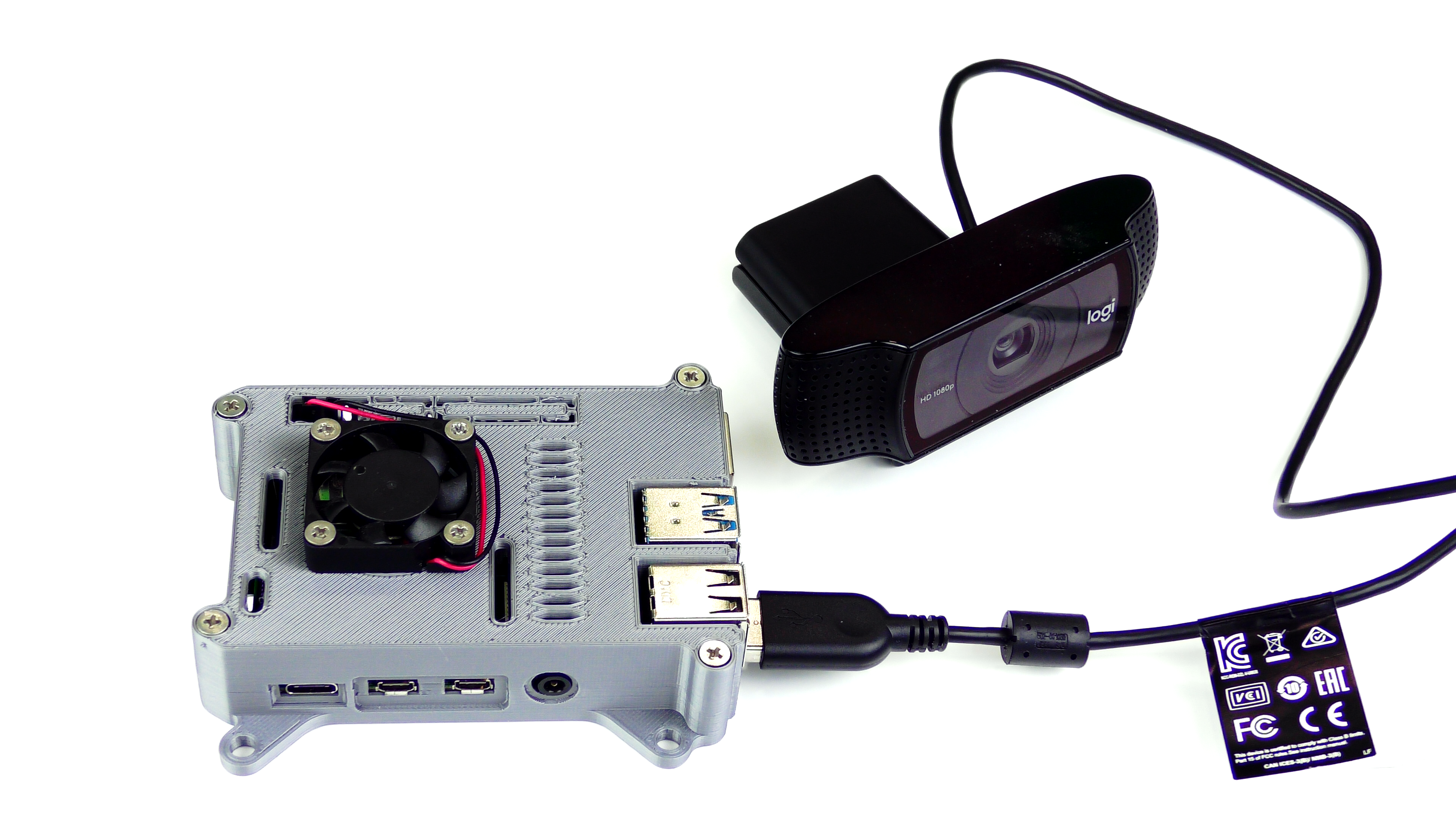
In this blog post, we show how to start with advanced analytics on streaming data coming from the shop floor. The sensor data, such as pressure and temperature, is typically published by a DCS. It is then ingested with a local edge gateway and streamed to the cloud with streaming and industrial internet of things (IoT) technology. Analytics on the streaming data is typically done before all data points are stored in the data layer. Figure 1 shows how the data flow can be modeled and visualized with AWS services.

Figure 1: High-level ingestion and analytics architecture
In this example, we are concentrating on the streaming analytics part in the Cloud. We will generate data from a simulated DCS to Amazon Kinesis Data Streams where you have a gateway such as AWS IoT Greengrass and maybe other IoT services in-between.
For the simulated process that the DCS is controlling, we use a well-documented industrial process for creating a chemical compound (acetic anhydride) called the Tennesee Eastman process (TEP). There are several simulations available as open source. We demonstrate how to use this data as a constant stream with more than 30 real-time measurement parameters, ingest to Kinesis Data Streams, and run in-stream analytics using Apache Flink. Within Apache Flink, data is grouped and mapped to the respective stages and parts of the industrial process, and constantly analyzed by calculating anomalies of all process stages. All raw data, plus the derived anomalies and failure patterns, are then ingested from Apache Flink to Amazon Timestream for further use in near real-time dashboards.
Overview of solution
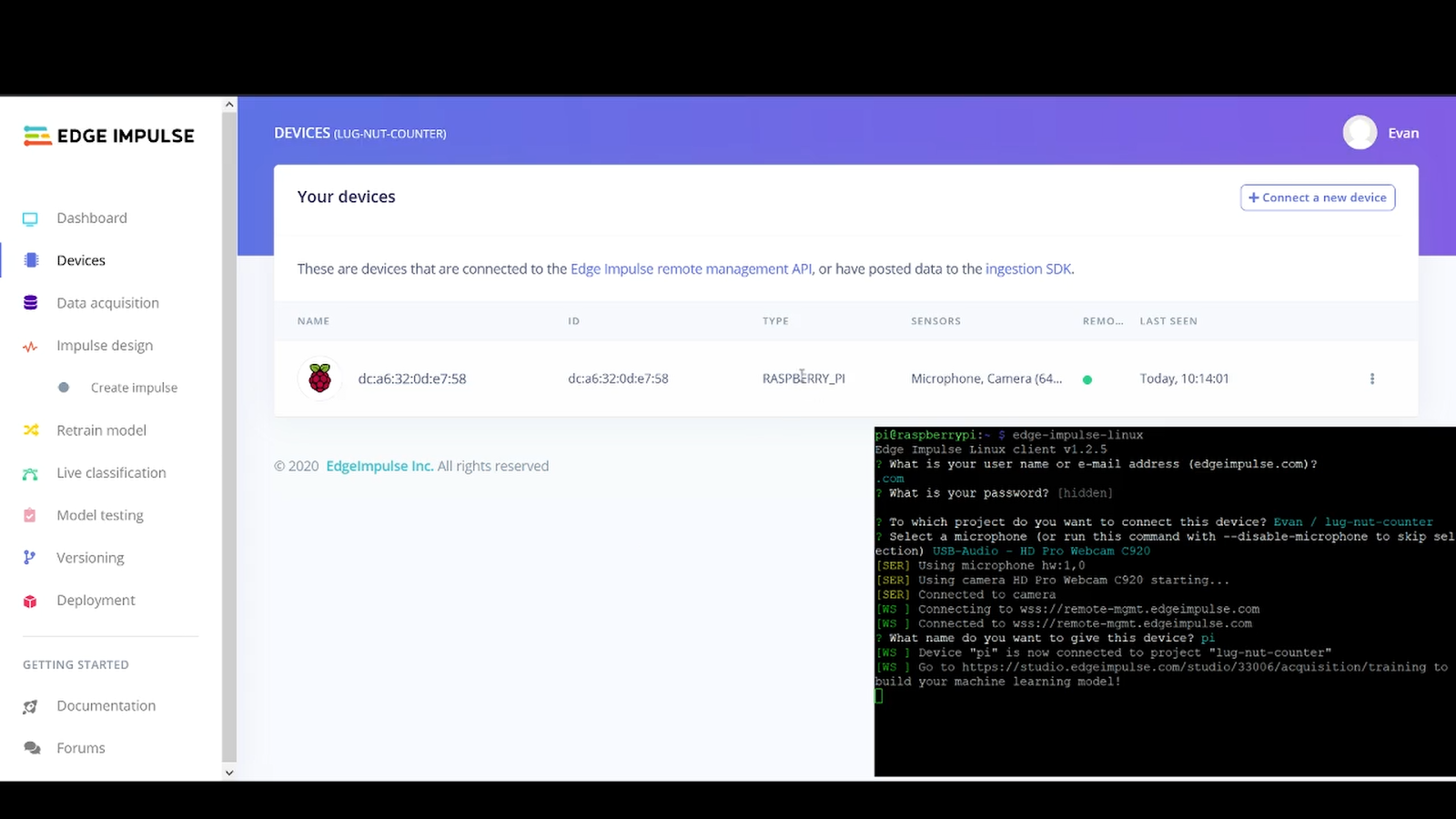
Note: Refer to steps 1 to 6 in Figure 2.
As a starting point for a realistic and data intensive measurement source, we use an already existing (TEP) simulation framework written in C++ originally created from National Institute of Standards and Technology, and published as open source. The GitHub Blog repository contains a small patch which adds AWS connectivity with the software development kits (SDKs) and modifications to the command line arguments. The programs provided by this framework are (step 1) a simulation process starter with configurable starting conditions and timestep configurations and a real-time client (step 2) which connects to the simulation and sends the simulation output data to the AWS Cloud.
Tennesee Eastman process (TEP) background
A paper by Downs & Vogel, A plant-wide industrial process control problem, from 1991 states:
“This chemical standard process consists of a reactor/separator/recycle arrangement involving two simultaneous gas-liquid exothermic reactions.”
“The process produces two liquid products from four reactants. Also present are an inert and a byproduct making a total of eight components. Two additional byproduct reactions also occur. The process has 12 valves available for manipulation and 41 measurements available for monitoring or control.“
The simulation framework used can control all of the 12 valve settings and produces 41 measurement variables with varying sampling frequency.
Data ingestion
The 41 measurement variables, named xmeas_1 to xmeas_41, are emitted by the real-time client (step 2) as key-value JSON messages. The client code is configured to produce 100 messages per second. A built-in C++ Kinesis SDK allows the real-time client to directly stream JSON messages to a Kinesis data stream (step 3).

Figure 2 – Detailed system architecture
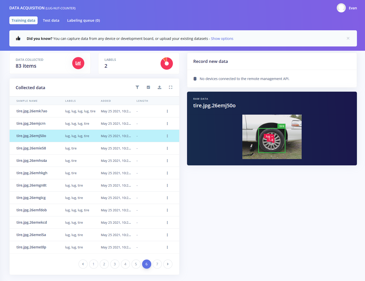
Stream processing with Apache Flink
Messages sent to Amazon Kinesis Data Stream are processed in configurable batch sizes by an Apache Flink application, deployed in Amazon Kinesis Data Analytics. Apache Flink is an open-source stream processing framework, written and usable in Java or Scala. As described in Figure 3, it allows the definition of various data sources (for example, a Kinesis data stream) and data sinks for storing processing results. In-between data can be processed by a range of operators—typically mapping and reducing functions (step 4).
In our case, we use a mapping operator where each batch of incoming messages is processed. In Code snippet 1, we apply a custom mapping function to the raw data stream. For rapid and iterative development purposes it’s possible to have the complete stream processing pipeline running in a local Java or Scala IDE such as Maven, Eclipse, or IntelliJ.

Figure 3: Flink execution plan (green: streaming data sources; yellow: data sinks)
public class StreamingJob extends AnomalyDetector {
---
  public static DataStream<String> createKinesisSource
    (StreamExecutionEnvironment env,
     ParameterTool parameter)
    {
    // create Stream
    return kinesisStream;
  }
---
  public static void main(String[] args) {
    // set up the execution environment
    final StreamExecutionEnvironment env =
      StreamExecutionEnvironment.getExecutionEnvironment();
---
    DataStream<List<TimestreamPoint>> mainStream =
      createKinesisSource(env, parameter)
      .map(new AnomalyJsonToTimestreamPayloadFn(parameter))
      .name("MaptoTimestreamPayload");
---
    env.execute("Amazon Timestream Flink Anomaly Detection Sink");
  }
}
Code snippet 1: Flink application main class
In-stream anomaly detection
Within the Flink mapping operator, a statistical outlier detection (anomaly detection) is implemented. Flink allows the inclusion of custom libraries within its operators. The library used here is published by AWS—a Random Cut Forest implementation available from GitHub. Random Cut Forest is a well understood statistical method which can operate on batches of measurements. It then calculates an anomaly score for each new measurement by comparing a new value with a cached pool (=forest) of older values.
The algorithm allows the creation of grouped anomaly scores, where a set of variables is combined to calculate a single anomaly score. In the simulated chemical process (TEP), we can group the measurement variables into three process stages:
- reactor feed analysis
- purge gas analysis
- product analysis.
Each group consists of 5–10 measurement variables. We’re getting anomaly scores for a, b, and c. In Code snippet 2 we can learn how an anomaly detector is created. The class AnomalyDetector is instantiated and extended then three times (for our three distinct process stages) within the mapping function as described in Code snippet 3.
Flink distributes this calculation across its worker nodes and handles data deduplication processes within its system.
---
public class AnomalyDetector {
    protected final ParameterTool parameter;
    protected final Function<RandomCutForest, LineTransformer> algorithmInitializer;
    protected LineTransformer algorithm;
    protected ShingleBuilder shingleBuilder;
    protected double[] pointBuffer;
    protected double[] shingleBuffer;
    public AnomalyDetector(
      ParameterTool parameter,
      Function<RandomCutForest,LineTransformer> algorithmInitializer)
    {
      this.parameter = parameter;
      this.algorithmInitializer = algorithmInitializer;
    }
    public List<String> run(Double[] values) {
            if (pointBuffer == null) {
                prepareAlgorithm(values.length);
            }
      return processLine(values);
    }
    protected void prepareAlgorithm(int dimensions) {
---
      RandomCutForest forest = RandomCutForest.builder()
        .numberOfTrees(Integer.parseInt(
          parameter.get("RcfNumberOfTrees", "50")))
        .sampleSize(Integer.parseInt(
          parameter.get("RcfSampleSize", "8192")))
        .dimensions(shingleBuilder.getShingledPointSize())
        .lambda(Double.parseDouble(
          parameter.get("RcfLambda", "0.00001220703125")))
        .randomSeed(Integer.parseInt(
          parameter.get("RcfRandomSeed", "42")))
      .build();
---
    algorithm = algorithmInitializer.apply(forest);
  }
Code snippet 2: AnomalyDetector base class, which gets extended by the streaming applications main class
public class AnomalyJsonToTimestreamPayloadFn extends
    RichMapFunction<String, List<TimestreamPoint>> {
  protected final ParameterTool parameter;
  private final Logger logger =

  public AnomalyJsonToTimestreamPayloadFn(ParameterTool parameter) {
    this.parameter = parameter;
  }

  // create new instance of StreamingJob for running our Forest
  StreamingJob overallAnomalyRunner1;
  StreamingJob overallAnomalyRunner2;
  StreamingJob overallAnomalyRunner3;
---

  // use `open`method as RCF initialization
  @Override
  public void open(Configuration parameters) throws Exception {
    overallAnomalyRunner1 = new StreamingJob(parameter);
    overallAnomalyRunner2 = new StreamingJob(parameter);
    overallAnomalyRunner3 = new StreamingJob(parameter);
  super.open(parameters);
}
---
Code snippet 3: Mapping Function uses the Flink RichMapFunction open routine to initialize three distinct Random Cut Forests
Data persistence – Flink data sinks
After all anomalies are calculated, we can decide where to send this data. Flink provides various ready-to-use data sinks. In these examples, we fan out all (raw and processed) data to Amazon Kinesis Data Firehose for storing in Amazon Simple Storage Service (Amazon S3) (long term) (step 5) and to Amazon Timestream (short term) (step 5). Kinesis Data Firehose is configured with a small AWS Lambda function to reformat data from JSON to CSV, and data is stored with automated partitioning to Amazon S3. A Timestream data sink does not come pre-bundled with Flink. A custom Timestream ingestion code is used in these examples. Flink provides extensible operator interfaces for the creation of custom map and sink functions.
Timeseries handling
Timestream, in combination with Grafana, is used for near real-time monitoring. Grafana comes bundled with a Timestream data source plugin and can constantly query and visualize Timestream data (step 6).
Walkthrough
Our architecture is available as a deployable AWS CloudFormation template. The simulation framework comes packed as a docker image, with an option to install it locally on a linux host.
Prerequisites
To implement this architecture, you will need:
- An AWS account
- Docker (CE) Engine v18++
- Java JDK v11++
- maven v3.6++
We recommend running a local and recent Linux environment. It is assumed that you are using AWS Cloud9, deployed with CloudFormation, within your AWS account.
Steps
Follow these steps to deploy the solution and play with the simulation framework. At the end, detected anomalies derived from Flink are stored next to all raw data in Timestream and presented in Grafana. We’re using AWS Cloud9 and its Linux terminal capabilities here to fire up a Grafana instance, then manually run the simulation to ingest data to Kinesis and optionally manually start the Flink app from the console using Maven.
Deploy stack
After you’re logged in to the AWS Management console you can deploy the CloudFormation stack. This stack creates a fully configured AWS Cloud9 environment with the related GitHub Repo already in place, a Kinesis data stream, Kinesis Data Firehose delivery stream, Kinesis Data Analytics with Flink app deployed, Timestream database, and an S3 bucket.
![]()
After successful deployment, record two important facts from the CloudFormation console: the chosen stack name and the attribute 03Cloud9EnvUrl displayed in the Output Section of the stack. The attribute’s URL will take you directly to our deployed AWS Cloud9 environment.
Run post install step within AWS Cloud9
The deployed stack created an AWS Cloud9 environment and an AWS Identity and Access Management (IAM) instance profile. We apply this instance profile to AWS Cloud9 to interact with Kinesis, Timestream, and Amazon S3 throughout the next steps. The used script also configures and installs other required tools.
1. Open a terminal window.
$ cd flinkAnomalySteps/deployment
$ source c9-postInstall.sh
---SETTING UP IAM INSTANCE PROFILE
Please enter cloudformation stack name (default: flink-rcf-app):
# enter your stack name
Start a Grafana development server
In this section we are starting a Grafana server using docker. Cloud 9 allows us to expose web applications (for demo & development purposes) on container port 8080.
1. Open a terminal window.
$ cd ../src/grafana-dashboard
$ docker volume create grafana-storage
# this creates a docker volume for persisting your Grafana settings
$./start-grafana.sh
# this starts a recent Grafana using docker with Timestream plugin and a pre-configured dashboard in place
2. Open the preview panel by selecting Preview, and then select Preview Running Application.
![]()
3. Next, in the preview pane, select Pop out into new Window.
![]()
4. A new browser tab with Grafana opens.
5. Choose any username and password combination.
6. In Grafana use the “Search dashboards” icon on the left and choose “TEP-SIM-DEV”. This pre-configured dashboard displays data from Amazon Timestream (see step “Open Grafana”).
TEP simulation procedure
Within your local or AWS Cloud9 Linux environment, fetch the simulation docker image from the public AWS container registry, or build the simulation binaries locally, for building manually check the GitHub repo.
Start simulation (in separate terminal)
# starts container and switch into the container-shell
$ docker run -it --rm \
  --network host \
  --name tesim-runner \
  tesim-runner:01 \
 /bin/bash
# then inside container
$ ./tesim --simtime 100  --external-ctrl
# simulation started…
Manipulate simulation (in separate terminal)
Follow the steps here for a basic process disturbance task. Review the aspects of influencing the simulation in the GitHub-Repo. The rtclient program has a range of commands to use for introducing disturbances.
# first switch into running simulation container
$ docker exec -it tesim-runner /bin/bash
# now we can access the shared storage of the simulation process…
$ ./rtclient –setidv 6
# this enables one of the built in process disturbances (1-20)
$ ./rtclient –setidv 7
$ ./rtclient –setidv 8
$ …
Stream Simulation data to Amazon Kinesis DataStream (in separate terminal)
The client has a built-in record frequency of 50 messages per second. One message contains more than 50 measurements, so we have approximately 2,500 measurements per second.
$ ./rtclient -k

AWS libcrypto resolve: found static libcrypto 1.1.1 HMAC symbols
AWS libcrypto resolve: found static libcrypto 1.1.1 EVP_MD symbols
{"xmeas_1": 3649.739476,"xmeas_2": 4451.32071,"xmeas_3": 9.223142558,"xmeas_4": 32.39290913,"xmeas_5": 47.55975621,"xmeas_6": 2798.975688,"xmeas_7": 64.99582601,"xmeas_8": 122.8987929,"xmeas_9": 0.1978264656,…}
# Messages in JSON sent to Kinesis DataStream visible via stdout
Compile and start Flink Application (optional step)
If you want deeper insights into the Flink Application, we can start this as well from the AWS Cloud9 instance. Note: this is only appropriate in development.
$ cd flinkAnomalySteps/src
$ cd flink-rcf-app
$ mvn clean compile
# the Flink app gets compiled
$ mvn exec:java -Dexec.mainClass= \
    "com.amazonaws.services.kinesisanalytics.StreamingJob"
# Flink App is started with default settings in place…
…
Open Grafana dashboard (from the step Start a Grafana development server)
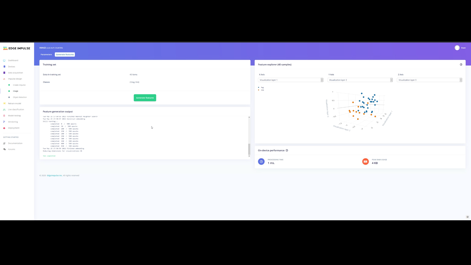
Process anomalies are visible instantly after you start the simulation. Use Grafana to drill down into the data as needed.
/**example - simplest possible Timestream query used for Viz:**/

SELECT CREATE_TIME_SERIES(time, measure_value::double) as anomaly_stream6 FROM "kdaflink"."kinesisdata1"

    WHERE measure_name='anomaly_score_stream6' AND

    time between ago(15m) and now()
Code snippet 4: Timestream SQL example; Timestream database is `kdaflink` – table is `kinesisdata1`

Figure 4 – Grafana dashboard showing near real-time simulation data, three anomalies, mapped to the TEP process, are constantly calculated by Flink
S3 raw metrics bucket
For the sake of completeness and potential usefulness, the Flink Application emits all raw data in an intermediate step to Kinesis Data Firehose. The service converts all JSON data to CSV format by using a small AWS Lambda function.
$ aws s3 ls flink-rcf-app-rawmetricsbucket-<CFN-UUID>/tep-raw-csv/2021/11/26/19/Cleaning up
Delete the deployed CloudFormation stack. All resources (excluding S3 buckets) are permanently deleted.
Conclusion
In this blog post, we learned that in-stream anomaly detection and constant measurement data insights can work together. The Apache Flink framework offers a ready-to-use platform that is mission critical for future adoption across manufacturing and other industries. Other applications of the presented Flink pattern can run on capable edge compute devices. Integration with AWS IoT Greengrass and AWS Greengrass Stream Manager are part of the GitHub Blog repository.
Another extension includes measurement data pattern detection routines, which can coexist with in-stream anomaly detection and can detect specific failure patterns over time using time-windowing features of the Flink framework. You can refer to the GitHub repo which accompanies this blog post. Give it a try and let us know your feedback in the comments!
 Before the end of the current LTS period, you will be able to use your AWS account to complete the FreeRTOS EMP registration on the FreeRTOS console, review and agree to the associated terms and conditions, select the LTS version, and buy an annual subscription. You will then gain access to the private repository where you’ll receive .zip files containing a git repo with chosen libraries, patches, and related notifications.
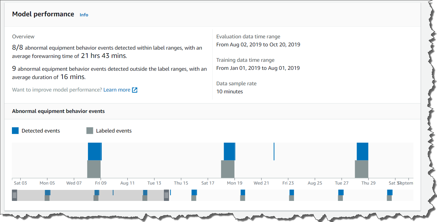
 Figure 1. AVA displays anomalies raised from L4E. A prediction score of > 0 indicates that an anomaly has been detected, and AVA will raise an issue with the underlying sensor details.


 And these represent only a fraction of what is possible. By moving certain workloads to the edge, your devices communicate with local compute resources and can respond more quickly to changes.