In 2022, we published Let’s Architect! Architecting microservices with containers. We covered integrations patterns and some approaches for implementing microservices using containers. In this Let’s Architect! post, we want to drill down into microservices only, by focusing on the main challenges that software architects and engineers face while working on large distributed systems structured as a set of independent services.
There are many considerations to cover in detail within a broad topic like microservices. We should reflect on the organizational structure, automation pipelines, multi-account strategy, testing, communication, and many other areas. With this post we dive deep into the topic by analyzing the options for discoverability and connectivity available through Amazon VPC Lattice; then, we focus on architectural patterns for communication, mainly on asynchronous communication, as it fits very well into the paradigm. Finally, we explore how to work with serverless microservices and analyze a case study from Amazon, coming directly from the Amazon Builder’s Library.
Modern applications are often built using a microservice distributed approach, which involves dividing the application into smaller, specialized services. Each of these services implement their own subset of functionalities or business logic. To facilitate communication between these services, it is essential to have a method to authorize, route, and monitor network traffic. It is also important, in case of issues, to have the ability of identifying the root cause of an issue, whether it originates at the application, service, or network level.
Amazon VPC Lattice can offer a consistent way to connect, secure, and monitor communication between instances, containers, and serverless functions. With Amazon VPC Lattice, you can define policies for traffic management, network access, advanced routing, implement discoverability, and, at the same time, monitor how the traffic is flowing inside complex applications in near real time.
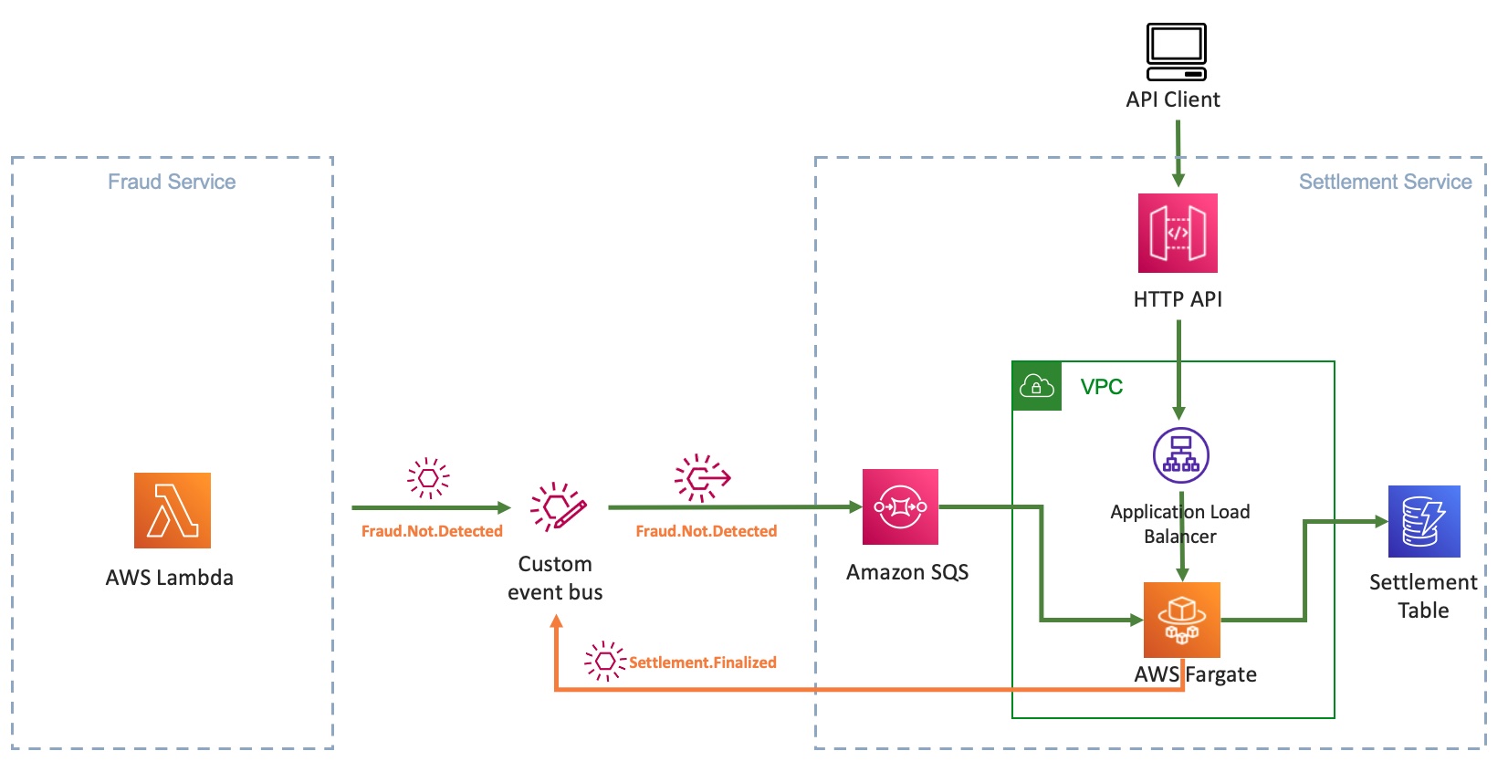
Loosely coupled integration can help you design independent systems that can be developed and operated individually, plus increase the availability and reliability of the overall system landscape—particularly by using asynchronous communication. While there are many approaches for integration and conversation scenarios, it’s not always clear which approach is best for a given situation.
Join this re:Invent 2022 session to learn about foundational patterns for integration and conversation scenarios with an emphasis on loose coupling and asynchronous communication. Explore real-world use cases architected with cloud-native and serverless services, and receive guidance on choosing integration technology.
Loosely coupled integration can help you design independent systems that can be developed and operated individually and can also increase the availability and reliability of the overall system
Software engineers love patterns—proven approaches to well-known problems that make software development easier and set our projects up for success. In complex, distributed systems, such as microservices, patterns like CQRS and Event Sourcing help decouple and scale systems.
The first part of the video is all about introducing architectural patterns and their applications, while the second part contains a set of demos and examples from the AWS console. In this session, we examine at some typical patterns for building robust and performant serverless microservices, and how data access patterns can drive polyglot persistence.
With event sourcing data is stored as a series of events, instead of direct updates to data stores; microservices replay events from an event store to compute the appropriate state of their own data stores
If we don’t pay attention to the relative scale of a service and its clients, distributed systems with microservices can be at risk of overload. A common architecture pattern adopted by many AWS services consists of splitting the system in a control plane and a data plane.
This article drills down into this scenario to understand what could happen if the data plane fleet exceeds the scale of the control plane fleet by a factor of 100 or more. This can happen in a microservices-based architecture when service X recovers from an outage and starts sending a large amount of request to service Y. Without careful fine-tuning, this shift in behavior can overwhelm the smaller callee. With this resource, we want to share some mental models and design strategies that are beneficial for distributed systems and teams working on microservices architectures.
To stay updated on the data plane’s operational state, the control plane can poll an Amazon S3 bucket into which data plane servers periodically write that information
See you next time!
Thanks for stopping by! Join us in two weeks when we’ll discuss multi-tenancy and patterns for SaaS on AWS.
“Our goal for LangChain is to empower developers around the world to build with AI. We want LangChain to work wherever developers are building, and to spark their creativity to build new and innovative applications. With this new launch, we can't wait to see what developers build with LangChainJS and Cloudflare Workers. And we're excited to put more of Cloudflare's developer tools in the hands of our community in the coming months.” – Harrison Chase, Co-Founder and CEO, LangChain
In this post, we’ll share why we’re so excited about LangChain and walk you through how to build your first LangChainJS + Cloudflare Workers application.
For the uninitiated, LangChain is a framework for building applications powered by large language models (LLMs). It not only lets you fairly seamlessly switch between different LLMs, but also gives you the ability to chain prompts together. This allows you to build more sophisticated applications across multiple LLMs, something that would be way more complicated without the help of LangChain.
Building your first LangChainJS + Cloudflare Workers application
There are a few prerequisites you have to set up in order to build this application:
An OpenAI account: If you don’t already have one, you can sign up for free.
A paid Cloudflare Workers account: If you don’t already have an account, you can sign up here and upgrade your Workers for $5 per month.
Node & npm: If this is your first time working with node, you can get it here.
Next create a new folder called langchain-workers, navigate into that folder and then within that folder run wrangler init.
When you run wrangler init you’ll select the following options:
✔Would you like to use git to manage this Worker? … yes
✔ No package.json found. Would you like to create one? … yes
✔ Would you like to use TypeScript? … no
✔ Would you like to create a Worker at src/index.js? › Fetch handler
✔ Would you like us to write your first test? … no
With our Worker created, we’ll need to set up the environment variable for our OpenAI API Key. You can create an API key in your OpenAI dashboard. Save your new API key someplace safe, then open your wrangler.toml file and add the following lines at the bottom (making sure to insert you actual API key):
[vars]
OPENAI_API_KEY = "sk…"
Then we’ll install LangChainjs using npm:
npm install langchain
Before we start writing code we can make sure everything is working properly by running wrangler dev. With wrangler dev running you can press b to open a browser. When you do, you'll see “Hello World!” in your browser.
A sample application
One common way you may want to use a language model is to combine it with your own text. LangChain is a great tool to accomplish this goal and that’s what we’ll be doing today in our sample application. We’re going to build an application that lets us use the OpenAI language model to ask a question about an article on Wikipedia. Because I live in (and love) Brooklyn, we’ll be using the Wikipedia article about Brooklyn. But you can use this code for any Wikipedia article, or website, you’d like.
Because language models only know about the data that they were trained on, if we want to use a language model with new or specific information we need a way to pass a model that information. In LangChain we can accomplish this using a ”document”. If you’re like me, when you hear “document” you often think of a specific file format but in LangChain a document is an object that consists of some text and optionally some metadata. The text in a document object is what will be used when interacting with a language model and the metadata is a way that you can track information about your document.
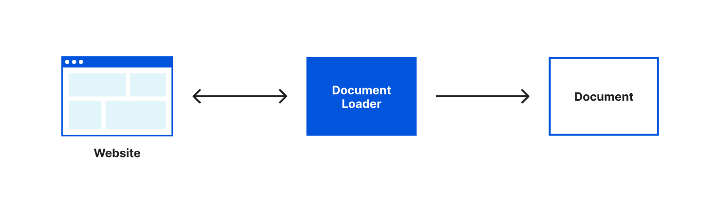
Most often you’ll want to create documents from a source of pre-existing text. LangChain helpfully provides us with different document loaders to make loading text from many different sources easy. There are document loaders for different types of text formats (for example: CSV, PDFs, HTML, unstructured text) and that content can be loaded locally or from the web. A document loader will both retrieve the text for you and load that text into a document object. For our application, we’ll be using the webpages with Cheerio document loader. Cheerio is a lightweight library that will let us read the content of a webpage. We can install it using npm install cheerio.
After we’ve installed cheerio we’ll import the CheerioWebBaseLoader at the top of our src/index.js file:
import { CheerioWebBaseLoader } from "langchain/document_loaders/web/cheerio";
With CheerioWebBaseLoader imported, we can start using it within our fetch function:.
In this code, we’re configuring our loader with the Wikipedia URL for the article about Brooklyn, run the load() function and log the result to the console. Like I mentioned earlier, if you want to try this with a different Wikipedia article or website, LangChain makes it very easy. All we have to do is change the URL we’re passing to our CheerioWebBaseLoader.
Let’s run wrangler dev, load up our page locally and watch the output in our console. You should see:
Loaded page
Array(1) [ Document ]
Our document loader retrieved the content of the webpage, put that content in a document object and loaded it into an array.
This is great, but there’s one more improvement we can make to this code before we move on – splitting our text into multiple documents.
Many language models have limits on the amount of text you can pass to them. As well, some LLM APIs charge based on the amount of text you send in your request. For both of these reasons, it’s helpful to only pass the text you need in a request to a language model.
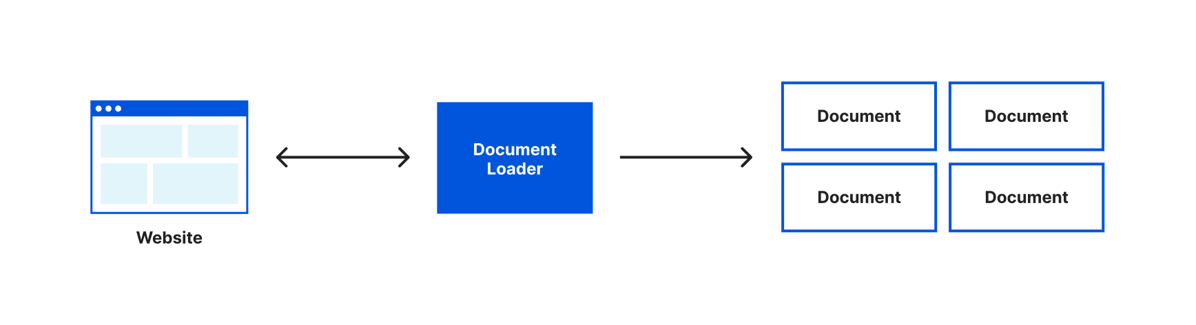
Currently, we’ve loaded the entire content of the Wikipedia page about Brooklyn into one document object and would send the entirety of that text with every request to our language model. It would be more efficient if we could only send the relevant text to our language model when we have a question. The first step in doing this is to split our text into smaller chunks that are stored in multiple document objects. To assist with this LangChain gives us the very aptly named Text Splitters.
We can use a text splitter by updating our loader to use the loadAndSplit() function instead of load(). Update the line where we assign docs to this:
const docs = await loader.loadAndSplit();
Now start the application again with wrangler dev and load our page. This time in our console you’ll see something like this:
Instead of an array with one document object, our document loader has now split the text it retrieved into multiple document objects. It’s still a single Wikipedia article, LangChain just split that text into chunks that would be more appropriately sized for working with a language model.
Even though our text is split into multiple documents, we still need to be able to understand what text is relevant to our question and should be sent to our language model. To do this, we’re going to introduce two new concepts – embeddings and vector stores.
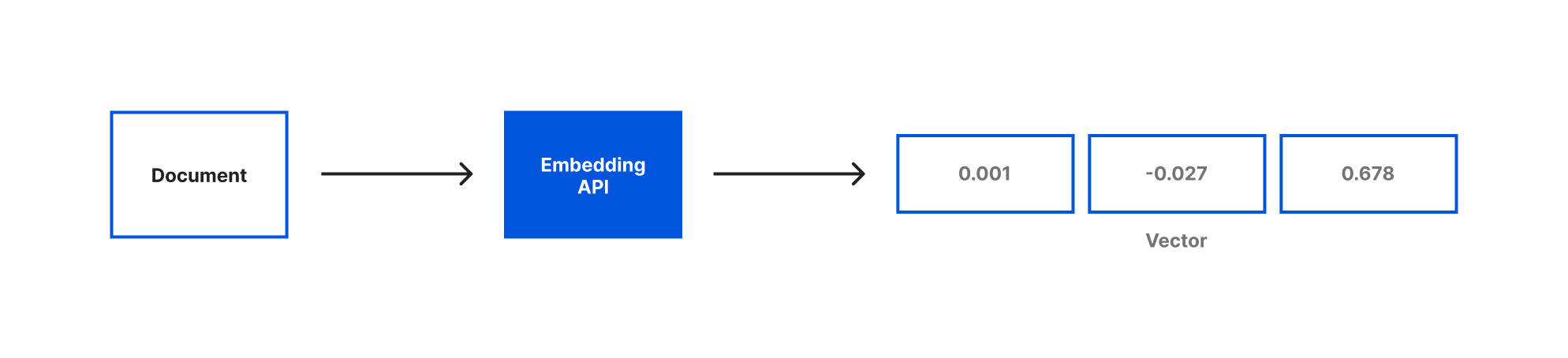
Embeddings are a way of representing text with numerical data. For our application we’ll be using OpenAI Embeddings to generate our embeddings based on the document objects we just created. When you generate embeddings the result is a vector of floating point numbers. This makes it easier for computers to understand the relatedness of the strings of text to each other. For each document object we pass the embedding API, a vector will be created.
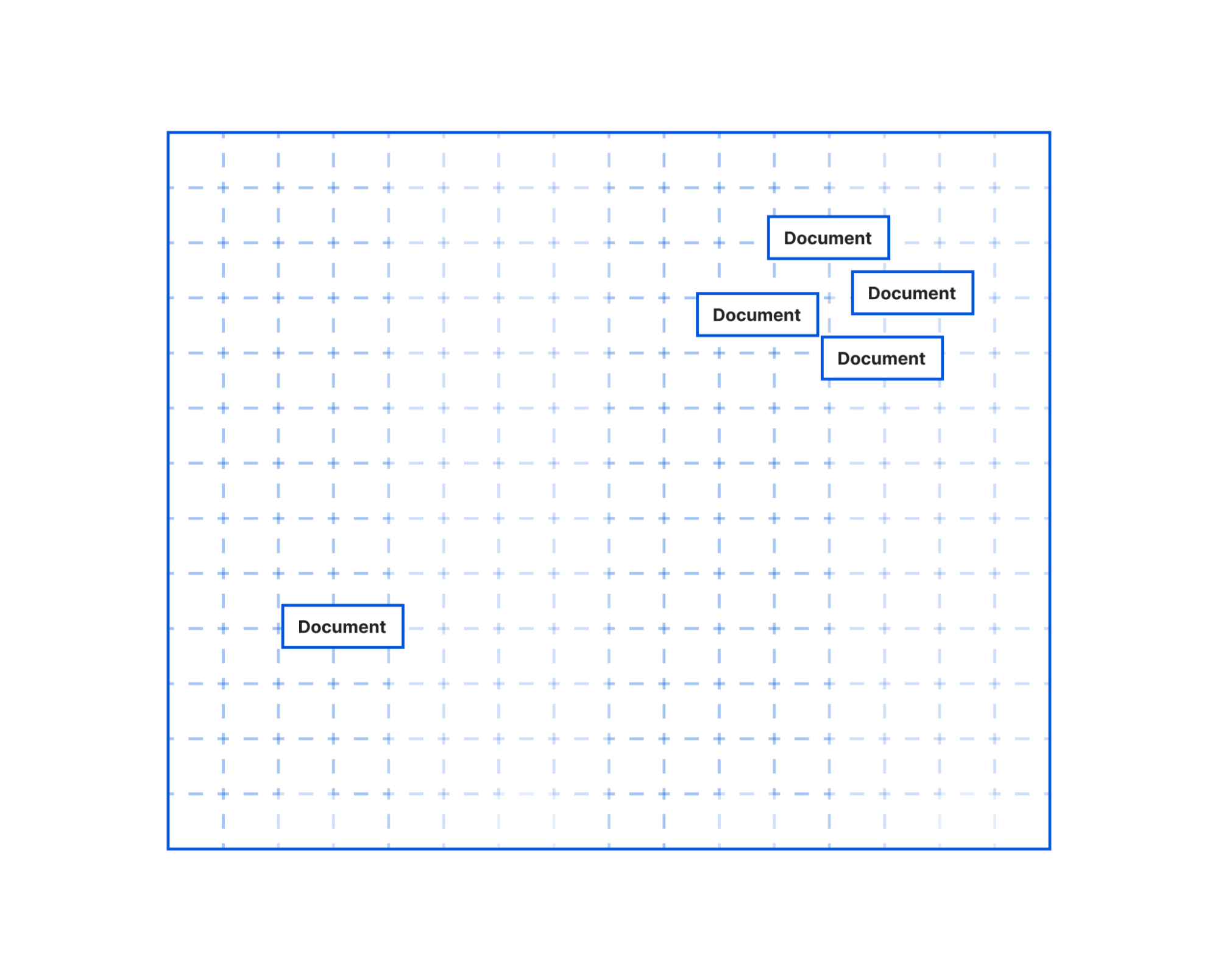
When we compare vectors, the closer numbers are to each other the more related the strings are. Inversely, the further apart the numbers are then the less related the strings are. It can be helpful to visualize how these numbers would allow us to place each document in a virtual space:
In this illustration, you could imagine how the text in the document objects that are bunched together would be more similar than the document object further off. The grouped documents could be text pulled from the article’s section on the history of Brooklyn. It’s a longer section that would have been split into multiple documents by our text splitter. But even though the text was split the embeddings would allow us to know this content is closely related to each other. Meanwhile, the document further away could be the text on the climate of Brooklyn. This section was smaller, not split into multiple documents, and the current climate is not as related to the history of Brooklyn, so it’s placed further away.
Embeddings are a pretty fascinating and complicated topic. If you’re interested in understanding more, here's a great explainer video that takes an in-depth look at the embeddings.
Once you’ve generated your documents and embeddings, you need to store them someplace for future querying. Vector stores are a kind of database optimized for storing & querying documents and their embeddings. For our vector store, we’ll be using MemoryVectorStore which is an ephemeral in-memory vector store. LangChain also has support for many of your favorite vector databases like Chroma and Pinecone.
We’ll start by adding imports for OpenAIEmbeddings and MemoryVectorStore at the top of our file:
import { OpenAIEmbeddings } from "langchain/embeddings/openai";
import { MemoryVectorStore } from "langchain/vectorstores/memory";
Then we can remove the console.log() function we had in place to show how our loader worked and replace them with the code to create our Embeddings and Vector store:
const store = await MemoryVectorStore.fromDocuments(docs, new OpenAIEmbeddings({ openAIApiKey: env.OPENAI_API_KEY}));
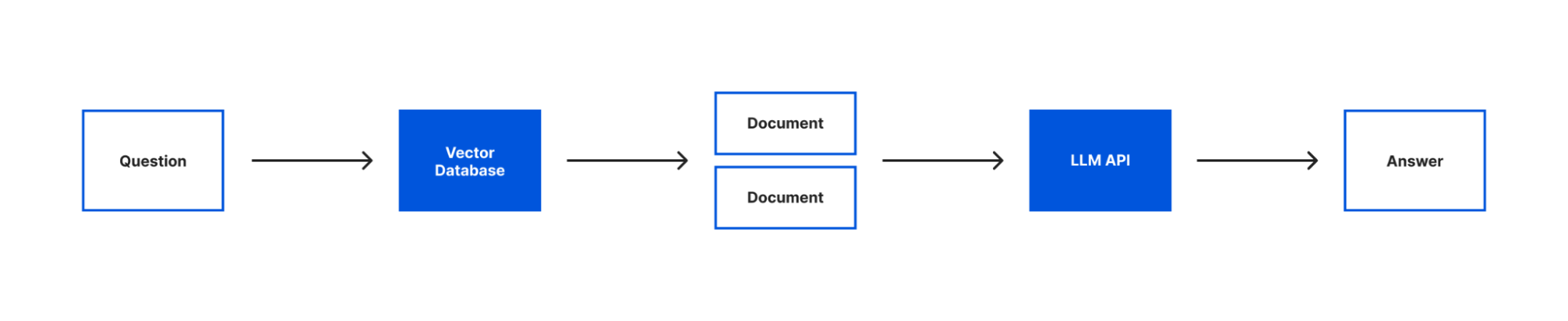
With our text loaded into documents, our embeddings created and both stored in a vector store we can now query our text with our language model. To do that we’re going to introduce the last two concepts that are core to building this application – models and chains.
When you see models in LangChain, it’s not about generating or creating models. Instead, LangChain provides a standard interface that lets you access many different language models. In this app, we’ll be using the OpenAI model.
Chains enable you to combine a language model with other sources of information, APIs, or even other language models. In our case, we’ll be using the RetreivalQAChain. This chain retrieves the documents from our vector store related to a question and then uses our model to answer the question using that information.
To start, we’ll add these two imports to the top of our file:
import { OpenAI } from "langchain/llms/openai";
import { RetrievalQAChain } from "langchain/chains";
Then we can put this all into action by adding the following code after we create our vector store:
        const model = new OpenAI({ openAIApiKey: env.OPENAI_API_KEY});
        const chain = RetrievalQAChain.fromLLM(model, store.asRetriever());

        const question = "What is this article about? Can you give me 3 facts about it?";

        const res = await chain.call({
            query: question,
        });

        return new Response(res.text);
In this code the first line is where we instantiate our model interface and pass it our API key. Next we create a chain passing it our model and our vector store. As mentioned earlier, we’re using a RetrievalQAChain which will look in our vector store for documents related to our query and then use those documents to get an answer for our query from our model.
With our chain created, we can call the chain by passing in the query we want to ask. Finally, we send the response text we got from our chain as the response to the request our Worker received. This will allow us to see the response in our browser.
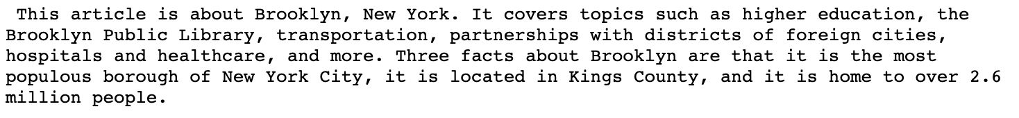
With all our code in place, let’s test it again by running wrangler dev. This time when you open your browser you will see a few facts about Brooklyn:
Right now, the question we’re asking is hard coded. Our goal was to be able to use LangChain to ask any question we want about this article. Let’s update our code to allow us to pass the question we want to ask in our request. In this case, we’ll pass a question as an argument in the query string (e.g. ?question=When was Brooklyn founded). To do this we’ll replace the line we’re currently assigning our question with the code needed to pull a question from our query string:
        const { searchParams } = new URL(request.url);
        const question = searchParams.get('question') ?? "What is this article about? Can you give me 3 facts about it?";
This code pulls all the query parameters from our URL using a JavaScript URL’s native searchParams property, and gets the value passed in for the “question” parameter. If a value isn’t present for the “question” parameter, we’ll use the default question text we were using previously thanks to JavaScripts’s nullish coalescing operator.
With this update, run wrangler dev and this time visit your local url with a question query string added. Now instead of giving us a few fun facts about Brooklyn, we get the answer of when Brooklyn was founded. You can try this with any question you may have about Brooklyn. Or you can switch out the URL in our document loader and try asking similar questions about different Wikipedia articles.
With our code working locally, we can deploy it with wrangler publish. After this command completes you’ll receive a Workers URL that runs your code.
You + LangChain + Cloudflare Workers
You can find our full LangChain example application on GitHub. We can’t wait to see what you all build with LangChain and Cloudflare Workers. Join us on Discord or tag us on Twitter as you’re building. And if you’re ever having any trouble or questions, you can ask on community.cloudflare.com.
We launched Workers for Platforms, our Workers offering for SaaS businesses, almost exactly one year ago to the date! We’ve seen a wide array of customers using Workers for Platforms – from e-commerce to CMS, low-code/no-code platforms and also a new wave of AI businesses running tailored inference models for their end customers!
Let’s take a look back and recap why we built Workers for Platforms, show you some of the most interesting problems our customers have been solving and share new features that are now available!
What is Workers for Platforms?
SaaS businesses are all too familiar with the never ending need to keep up with their users' feature requests. Thinking back, the introduction of Workers at Cloudflare was to solve this very pain point. Workers gave our customers the power to program our network to meet their specific requirements!
Need to implement complex load balancing across many origins? Write a Worker. Want a custom set of WAF rules for each region your business operates in? Go crazy, write a Worker.
We heard the same themes coming up with our customers – which is why we partnered with early customers to build Workers for Platforms. We worked with the Shopify Oxygen team early on in their journey to create a built-in hosting platform for Hydrogen, their Remix-based eCommerce framework. Shopify’s Hydrogen/Oxygen combination gives their merchants the flexibility to build out personalized shopping for buyers. It’s an experience that storefront developers can make their own, and it’s powered by Cloudflare Workers behind the scenes. For more details, check out Shopify’s “How we Built Oxygen” blog post.
Oxygen is Shopify's built-in hosting platform for Hydrogen storefronts, designed to provide users with a seamless experience in deploying and managing their ecommerce sites. Our integration with Workers for Platforms has been instrumental to our success in providing fast, globally-available, and secure storefronts for our merchants. The flexibility of Cloudflare's platform has allowed us to build delightful merchant experiences that integrate effortlessly with the best that the Shopify ecosystem has to offer. – Lance Lafontaine, Senior Developer Shopify Oxygen
Another customer that we’ve been working very closely with is Grafbase. Grafbase started out on the Cloudflare for Startups program, building their company from the ground up on Workers. Grafbase gives their customers the ability to deploy serverless GraphQL backends instantly. On top of that, their developers can build custom GraphQL resolvers to program their own business logic right at the edge. Using Workers and Workers for Platforms means that Grafbase can focus their team on building Grafbase, rather than having to focus on building and architecting at the infrastructure layer.
Our mission at Grafbase is to enable developers to deploy globally fast GraphQL APIs without worrying about complex infrastructure. We provide a unified data layer at the edge that accelerates development by providing a single endpoint for all your data sources. We needed a way to deploy serverless GraphQL gateways for our customers with fast performance globally without cold starts. We experimented with container-based workloads and FaaS solutions, but turned our attention to WebAssembly (Wasm) in order to achieve our performance targets. We chose Rust to build the Grafbase platform for its performance, type system, and its Wasm tooling. Cloudflare Workers was a natural fit for us given our decision to go with Wasm. On top of using Workers to build our platform, we also wanted to give customers the control and flexibility to deploy their own logic. Workers for Platforms gave us the ability to deploy customer code written in JavaScript/TypeScript or Wasm straight to the edge. – Fredrik Björk, Founder & CEO at Grafbase
Over the past year, it’s been incredible seeing the velocity that building on Workers allows companies both big and small to move at.
New building blocks
Workers for Platforms uses Dynamic Dispatch to give our customers, like Shopify and Grafbase, the ability to run their own Worker before user code that’s written by Shopify and Grafbase’s developers is executed. With Dynamic Dispatch, Workers for Platforms customers (referred to as platform customers) can authenticate requests, add context to a request or run any custom code before their developer’s Workers (referred to as user Workers) are called.
This is a key building block for Workers for Platforms, but we’ve also heard requests for even more levels of visibility and control from our platform customers. Delivering on this theme, we’re releasing three new highly requested features:
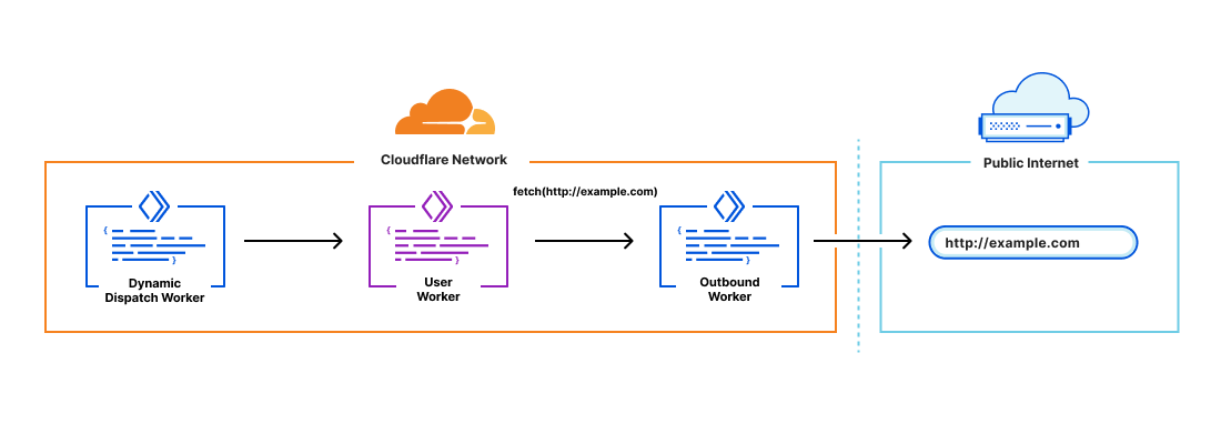
Outbound Workers
Dynamic Dispatch gives platforms visibility into all incoming requests to their user’s Workers, but customers have also asked for visibility into all outgoing requests from their user’s Workers in order to do things like:
Log all subrequests in order to identify malicious hosts or usage patterns
Create allow or block lists for hostnames requested by user Workers
Configure authentication to your APIs behind the scenes (without end developers needing to set credentials)
Outbound Workers sit between user Workers and fetch() requests out to the Internet. User Workers will trigger a FetchEvent on the Outbound Worker and from there platform customers have full visibility over the request before it’s sent out.
It’s also important to have context in the Outbound Worker to answer questions like “which user Worker is this request coming from?”. You can declare variables to pass through to the Outbound Worker in the dispatch namespaces binding:
From there, the variables declared in the binding can be accessed in the Outbound Worker through env. <VAR_NAME>.
Custom Limits
Workers are really powerful, but, as a platform, you may want guardrails around their capabilities to shape your pricing and packaging model. For example, if you run a freemium model on your platform, you may want to set a lower CPU time limit for customers on your free tier.
Custom Limits let you set usage caps for CPU time and number of subrequests on your customer’s Workers. Custom limits are set from within your dynamic dispatch Worker allowing them to be dynamically scripted. They can also be combined to set limits based on script tags.
Here’s an example of a Dynamic Dispatch Worker that puts both Outbound Workers and Custom Limits together:
export default {
async fetch(request, env) {
  try {
    let workerName = new URL(request.url).host.split('.')[0];
    let userWorker = env.dispatcher.get(
      workerName,
      {},
      {// outbound arguments
       outbound: {
           customer_name: workerName,
           url: request.url},
        // set limits
       limits: {cpuMs: 10, subRequests: 5}
      }
    );
    return await userWorker.fetch(request);
  } catch (e) {
    if (e.message.startsWith('Worker not found')) {
      return new Response('', { status: 404 });
    }
    return new Response(e.message, { status: 500 });
  }
}
};
They’re both incredibly simple to configure, and the best part – the configuration is completely programmatic. You have the flexibility to build on both of these features with your own custom logic!
Tail Workers
Live logging is an essential piece of the developer experience. It allows developers to monitor for errors and troubleshoot in real time. On Workers, giving users real time logs though wrangler tail is a feature that developers love! Now with Tail Workers, platform customers can give their users the same level of visibility to provide a faster debugging experience.
Tail Worker logs contain metadata about the original trigger event (like the incoming URL and status code for fetches), console.log() messages and capture any unhandled exceptions. Tail Workers can be added to the Dynamic Dispatch Worker in order to capture logs from both the Dynamic Dispatch Worker and any User Workers that are called.
A Tail Worker can be configured by adding the following to the wrangler.toml file of the producing script
Tail Workers are full-fledged Workers empowered by the usual Worker ecosystem. You can send events to any HTTP endpoint, like for example a logging service that parses the events and passes on real-time logs to customers.
Try it out!
All three of these features are now in open beta for users with access to Workers for Platforms. For more details and try them out for yourself, check out our developer documentation:
Workers for Platforms is an enterprise only product (for now) but we’ve heard a lot of interest from developers. In the later half of the year, we’ll be bringing Workers for Platforms down to our pay as you go plan! In the meantime, if you’re itching to get started, reach out to us through the Cloudflare Developer Discord (channel name: workers-for-platforms).
If your decentralized application (dApp) must interact directly with AWS services like Amazon S3 or Amazon API Gateway, you must authorize your users by granting them temporary AWS credentials. This solution uses Amazon Cognito in combination with your users’ digital wallet to obtain valid Amazon Cognito identities and temporary AWS credentials for your users. It also demonstrates how to use Amazon API Gateway to secure and proxy API calls to third-party Web3 APIs.
In this blog, you will build a fully serverless decentralized application (dApp) called “NFT Gallery”. This dApp permits users to look up their own non-fungible token (NFTs) or any other NFT collections on the Ethereum blockchain using one of the following two Web3 providers HTTP APIs: Alchemy or Moralis. These APIs help integrate Web3 components in any web application without Blockchain technical knowledge or access.
Solution overview
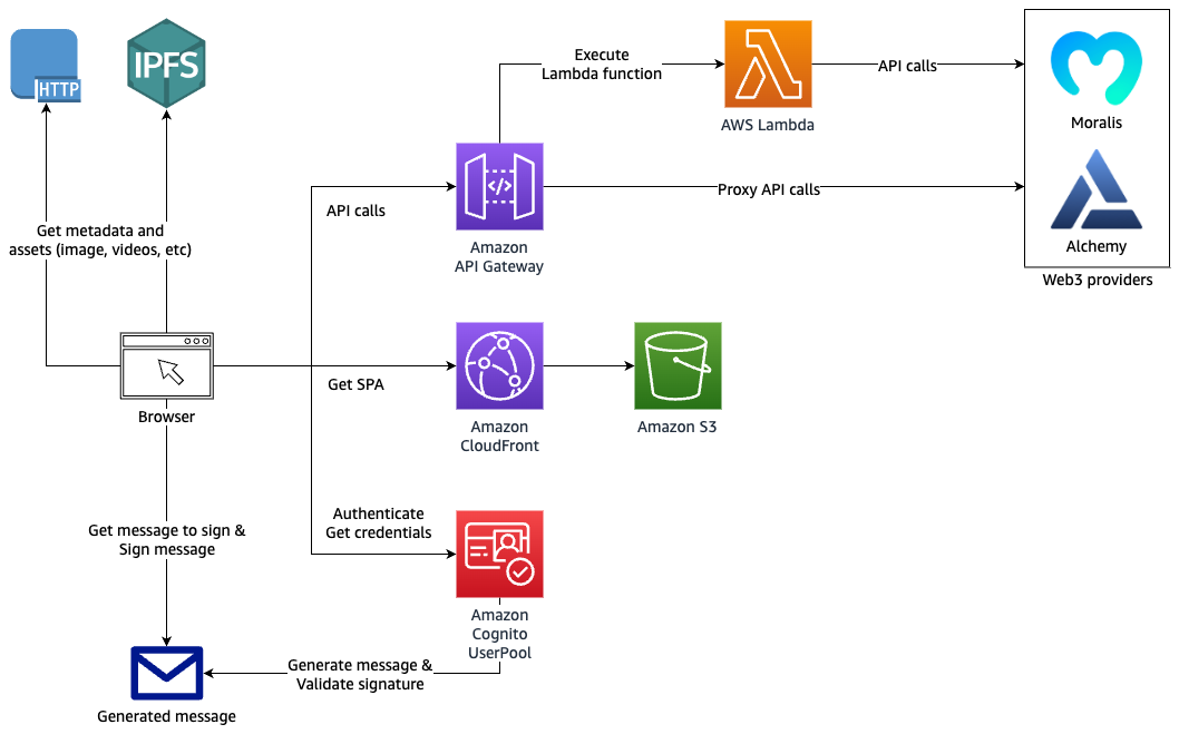
The user interface (UI) of your dApp is a single-page application (SPA) written in JavaScript using ReactJS, NextJS, and Tailwind CSS.
The dApp interacts with Amazon Cognito for authentication and authorization, and with Amazon API Gateway to proxy data from the backend Web3 providers’ APIs.
Architecture diagram
Figure 1. Architecture diagram showing authentication and API request proxy solution for Web3
You’ll use AWS SAM as your framework to define, build, and deploy your backend resources. AWS SAM is built on top of AWS CloudFormation and enables developers to define serverless components using a simpler syntax.
backend: contains the AWS SAM Template template.yaml. Examine the template.yaml file for more information about the resources deployed in this project.
dapp: contains the code for the dApp
1. Go to the backend folder and copy the prod.parameters.example file to a new file called prod.parameters. Edit it to add your Alchemy and Moralis API keys.
3. You can now deploy the SAM Template by running the following command (review the sam deploy Developer Guide).
sam deploy --parameter-overrides $(cat prod.parameters) --capabilities CAPABILITY_NAMED_IAM --guided --confirm-changeset
4. SAM will ask you some questions and will generate a samconfig.toml containing your answers.
You can edit this file afterwards as desired. Future deployments will use the .toml file and can be run using sam deploy. Don’t commit the samconfig.toml file to your code repository as it contains private information.
Your CloudFormation stack should be deployed after a few minutes. The Outputs should show the resources that you must reference in your web application located in the dapp folder.
Run the dApp
You can now run your dApp locally.
1. Go to the dapp folder and copy the .env.example file to a new file named .env. Edit this file to add the backend resources values needed by the dApp. Follow the instructions in the .env.example file.
2. Run the following command to install the JavaScript dependencies:
yarn
3. Start the development web server locally by running:
You can access your dApp from the internet with the URL of the CloudFront distribution. It is visible in your CloudFormation stack Output tab in the AWS Management Console, or as output of the sam deploy command.
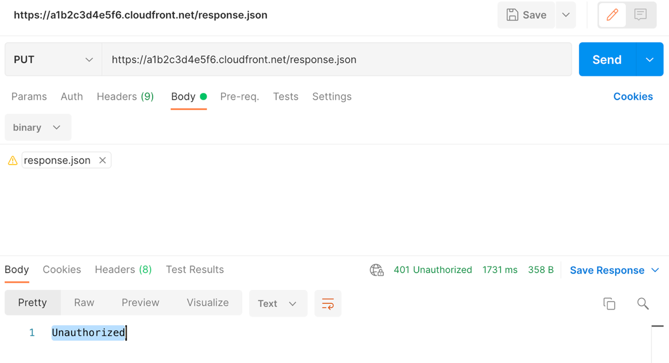
For now, your S3 bucket is empty. Build the dApp for production and upload the code to the S3 bucket by running these commands:
cd dapp yarn build cd out aws s3 sync . s3://${BUCKET_NAME}
Replace ${BUCKET_NAME} by the name of your S3 bucket.
Automate deployment using SAM Pipelines
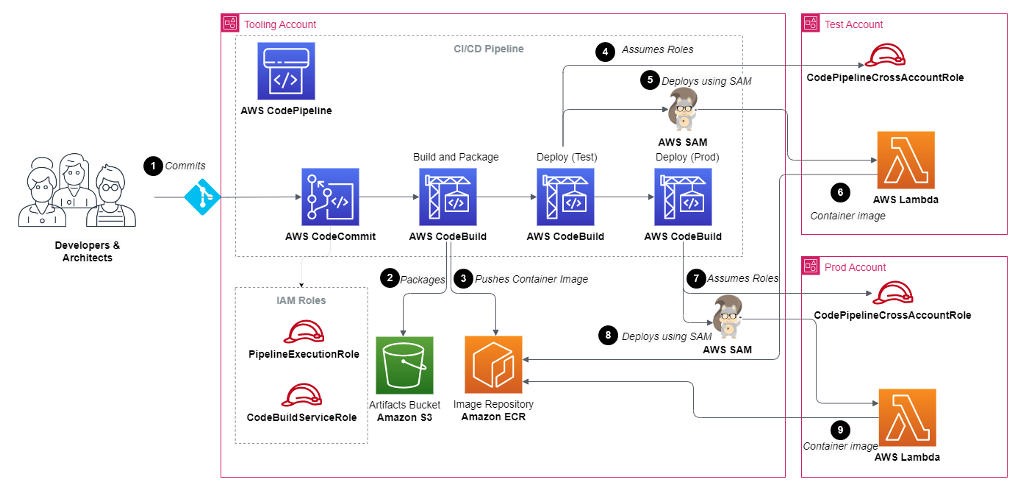
SAM Pipelines automatically generates deployment pipelines for serverless applications. If changes are committed to your Git repository, it automates the deployment of your CloudFormation stack and dApp code.
With SAM Pipeline, you can choose a Git provider like AWS CodeCommit, and a build environment like AWS CodePipeline to automatically provision and manage your deployment pipeline. It also supports GitHub Actions.
Host your dApp using Interplanetary File System (IPFS)
IPFS is a good solution to host dApps in a decentralized way. IPFS Gateway can serve as Origin to your CloudFront distribution and serve IPFS content over HTTP.
dApps are often hosted on IPFS to increase trust and transparency. With IPFS, your web application source code and assets are not tied to a DNS name and a specific HTTP host. They will live independently on the IPFS network.
Your dApp is usable by both authenticated and unauthenticated users. Unauthenticated users can look up NFT collections while authenticated users can also look up their own NFTs.
In your dApp, there is no login/password combination or Identity Provider (IdP) in place to authenticate your users. Instead, users connect their digital wallet to the web application.
You can create a custom authentication flow by implementing an Amazon Cognito custom authentication challenge, which uses AWS Lambda triggers. This challenge requires your users to sign a generated message using their digital wallet. If the signature is valid, it confirms that the user owns this wallet address. The wallet address is then used as a user identifier in the Amazon Cognito user pool.
Figure 2 details the Amazon Cognito authentication process. Three Lambda functions are used to perform the different authentication steps.
Figure 2. Amazon Cognito authentication process
To define the authentication success conditions, the Amazon Cognito user pool calls the “Define auth challenge” Lambda function (defineAuthChallenge.js).
To generate the challenge, Amazon Cognito calls the “Create auth challenge” Lambda function (createAuthChallenge.js). In this case, it generates a random message for the user to sign. Amazon Cognito forwards the challenge to the dApp, which prompts the user to sign the message using their digital wallet and private key. The dApp then returns the signature to Amazon Cognito as a response.
To verify if the user’s wallet effectively signed the message, Amazon Cognito forwards the user’s response to the “Verify auth challenge response” Lambda function (verifyAuthChallengeResponse.js). If True, then Amazon Cognito authenticates the user and creates a new identity in the user pool with the wallet address as username.
Finally, Amazon Cognito returns a JWT Token to the dApp containing multiple claims, one of them being cognito:username, which contains the user’s wallet address. These claims will be passed to your AWS Lambda event and Amazon API Gateway mapping templates allowing your backend to securely identify the user making those API requests.
Authorization
Amazon API Gateway offers multiple ways of authorizing access to an API route. This example showcases three different authorization methods:
AWS_IAM: Authorization with IAM Roles. IAM roles grant access to specific API routes or any other AWS resources. The IAM Role assumed by the user is granted by Amazon Cognito identity pool.
COGNITO_USER_POOLS: Authorization with Amazon Cognito user pool. API routes are protected by validating the user’s Amazon Cognito token.
NONE: No authorization. API routes are open to the public internet.
API Gateway backend integrations
HTTP proxy integration
The HTTP proxy integration method allows you to proxy HTTP requests to another API. The requests and responses can passthrough as-is, or you can modify them on the fly using Mapping Templates.
This method is a cost-effective way to secure access to any third-party API. This is because your third-party API keys are stored in your API Gateway and not on the frontend application.
You can also activate caching on API Gateway to reduce the amount of API calls made to the backend APIs. This will increase performance, reduce cost, and control usage.
Inspect the GetNFTsMoralisGETMethod and GetNFTsAlchemyGETMethod resources in the SAM template to understand how you can use Mapping Templates to modify the headers, path, or query string of your incoming requests.
Lambda proxy integration
API Gateway can use AWS Lambda as backend integration. Lambda functions enable you to implement custom code and logic before returning a response to your dApp.
In the backend/src folder, you will find two Lambda functions:
getNFTsMoralisLambda.js: Calls Moralis API and returns raw response
getNFTsAlchemyLambda.js: Calls Alchemy API and returns raw response
To access your authenticated user’s wallet address from your Lambda function code, access the cognito:username claim as follows:
var wallet_address = event.requestContext.authorizer.claims["cognito:username"];
Using Amplify Libraries in the dApp
The dApp uses the AWS Amplify Javascript Libraries to interact with Amazon Cognito user pool, Amazon Cognito identity pool, and Amazon API Gateway.
With Amplify Libraries, you can interact with the Amazon Cognito custom authentication flow, get AWS credentials for your frontend, and make HTTP API calls to your API Gateway endpoint.
The Amplify Auth library is used to perform the authentication flow. To sign up, sign in, and respond to the Amazon Cognito custom challenge, use the Amplify Auth library. Examine the ConnectButton.js and user.js files in the dapp folder.
To make API calls to your API Gateway, you can use the Amplify API library. Examine the api.js file in the dApp to understand how you can make API calls to different API routes. Note that some are protected by AWS_IAM authorization and others by COGNITO_USER_POOL.
Based on the current authentication status, your users will automatically assume the CognitoAuthorizedRole or CognitoUnAuthorizedRole IAM Roles referenced in the Amazon Cognito identity pool. AWS Amplify will automatically use the credentials associated with your AWS IAM Role when calling an API route protected by the AWS_IAM authorization method.
Amazon Cognito identity pool allows anonymous users to assume the CognitoUnAuthorizedRole IAM Role. This allows secure access to your API routes or any other AWS services you configured, even for your anonymous users. Your API routes will then not be publicly available to the internet.
Cleaning up
To avoid incurring future charges, delete the CloudFormation stack created by SAM. Run the sam delete command or delete the CloudFormation stack in the AWS Management Console directly.
Conclusion
In this blog, we’ve demonstrated how to use different AWS managed services to run and deploy a decentralized web application (dApp) on AWS. We’ve also shown how to integrate securely with Web3 providers’ APIs, like Alchemy or Moralis.
You can use Amazon Cognito user pool to create a custom authentication challenge and authenticate users using a cryptographically signed message. And you can secure access to third-party APIs, using API Gateway and keep your secrets safe on the backend.
Finally, you’ve seen how to host a single-page application (SPA) using Amazon S3 and Amazon CloudFront as your content delivery network (CDN).
Cloudflare Pages launched over two years ago in December 2020, and since then, we have grown Pages to build millions of deployments for developers. In May 2022, to support developers with more complex requirements, we opened up Pages to empower developers to create deployments using their own build environments — but that wasn't the end of our journey. Ultimately, we want to be able to allow anyone to use our build platform and take advantage of the git integration we offer. You should be able to connect your repository and have it just work on Cloudflare Pages.
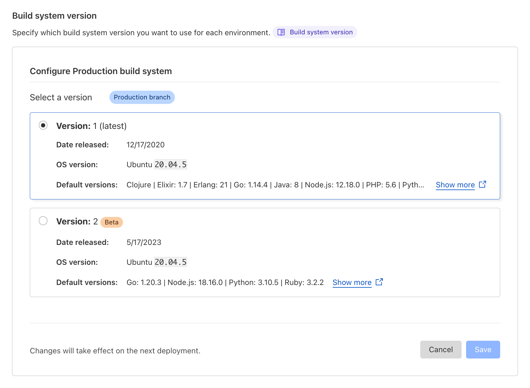
Today, we're introducing a new beta version of our build system (a.k.a. "build image") which brings the default set of tools and languages up-to-date, and sets the stage for future improvements to builds on Cloudflare Pages. We now support the latest versions of Node.js, Python, Hugo and many more, putting you on the best path for any new projects that you undertake. Existing projects will continue to use the current build system, but this upgrade will be available to opt-in for everyone.
New defaults, new possibilities
The Cloudflare Pages build system has been updated to not only support new versions of your favorite languages and tools, but to also include new versions by default. The versions of 2020 are no longer relevant for the majority of today's projects, and as such, we're bumping these to their more modern equivalents:
Node.js' default is being increased from 12.18.0 to 18.16.0,
Python 2.7.18 and 3.10.5 are both now available by default,
Ruby's default is being increased from 2.7.1 to 3.2.2,
Yarn's default is being increased from 1.22.4 to 3.5.1,
And we're adding pnpm with a default version of 8.2.0.
These are just some of the headlines — check out our documentation for the full list of changes.
We're aware that these new defaults constitute a breaking change for anyone using a project without pinning their versions with an environment variable or version file. That's why we're making this new build system opt-in for existing projects. You'll be able to stay on the existing system without breaking your builds. If you do decide to adventure with us, we make it easy to test out the new system in your preview environments before rolling out to production.
Additionally, we're now making your builds more reproducible by taking advantage of lockfiles with many package managers. npm ci and yarn --pure-lockfile are now used ahead of your build command in this new version of the build system.
For new projects, these updated defaults and added support for pnpm and Yarn 3 mean that more projects will just work immediately without any undue setup, tweaking, or configuration. Today, we're launching this update as a beta, but we will be quickly promoting it to general availability once we're satisfied with its stability. Once it does graduate, new projects will use this updated build system by default.
We know that this update has been a long-standing request from our users (we thank you for your patience!) but part of this rollout is ensuring that we are now in a better position to make regular updates to Cloudflare Pages' build system. You can expect these default languages and tools to now keep pace with the rapid rate of change seen in the world of web development.
We very much welcome your continued feedback as we know that new tools can quickly appear on the scene, and old ones can just as quickly drop off. As ever, our Discord server is the best place to engage with the community and Pages team. We’re excited to hear your thoughts and suggestions.
Our modular and scalable architecture
Powering this updated build system is a new architecture that we've been working on behind-the-scenes. We're no strangers to sweeping changes of our build infrastructure: we've done a lot of work to grow and scale our infrastructure. Moving beyond purely static site hosting with Pages Functions brought a new wave of users, and as we explore convergence with Workers, we expect even more developers to rely on our git integrations and CI builds. Our new architecture is being rolled out without any changes affecting users, so unless you're interested in the technical nitty-gritty, feel free to stop reading!
The biggest change we're making with our architecture is its modularity. Previously, we were using Kubernetes to run a monolithic container which was responsible for everything for the build. Within the same image, we'd stream our build logs, clone the git repository, install any custom versions of languages and tools, install a project's dependencies, run the user's build command, and upload all the assets of the build. This was a lot of work for one container! It meant that our system tooling had to be compatible with versions in the user's space and therefore new default versions were a massive change to make. This is a big part of why it took us so long to be able to update the build system for our users.
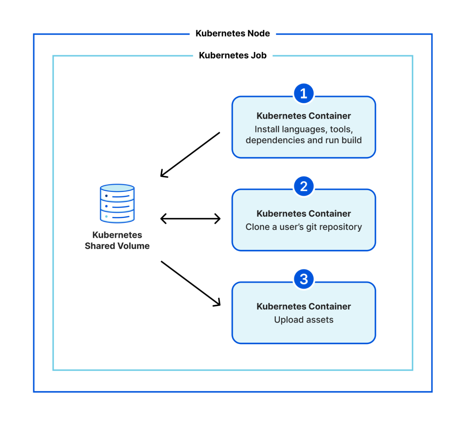
In the new architecture, we've broken these steps down into multiple separate containers. We make use of Kubernetes' init containers feature and instead of one monolithic container, we have three that execute sequentially:
clone a user's git repository,
install any custom versions of languages and tools, install a project's dependencies, run the user's build command, and
upload all the assets of a build.
We use a shared volume to give the build a persistent workspace to use between containers, but now there is clear isolation between system stages (cloning a repository and uploading assets) and user stages (running code that the user is responsible for). We no longer need to worry about conflicting versions, and we've created an additional layer of security by isolating a user's control to a separate environment.
We're also aligning the final stage, the one responsible for uploading static assets, with the same APIs that Wrangler uses for Direct Upload projects. This reduces our maintenance burden going forward since we'll only need to consider one way of uploading assets and creating deployments. As we consolidate, we're exploring ways to make these APIs even faster and more reliable.
Logging out
You might have noticed that we haven't yet talked about how we're continuing to stream build logs. Arguably, this was one of the most challenging pieces to work out. When everything ran in a single container, we were able to simply latch directly into the stdout of our various stages and pipe them through to a Durable Object which could communicate with the Cloudflare dashboard.
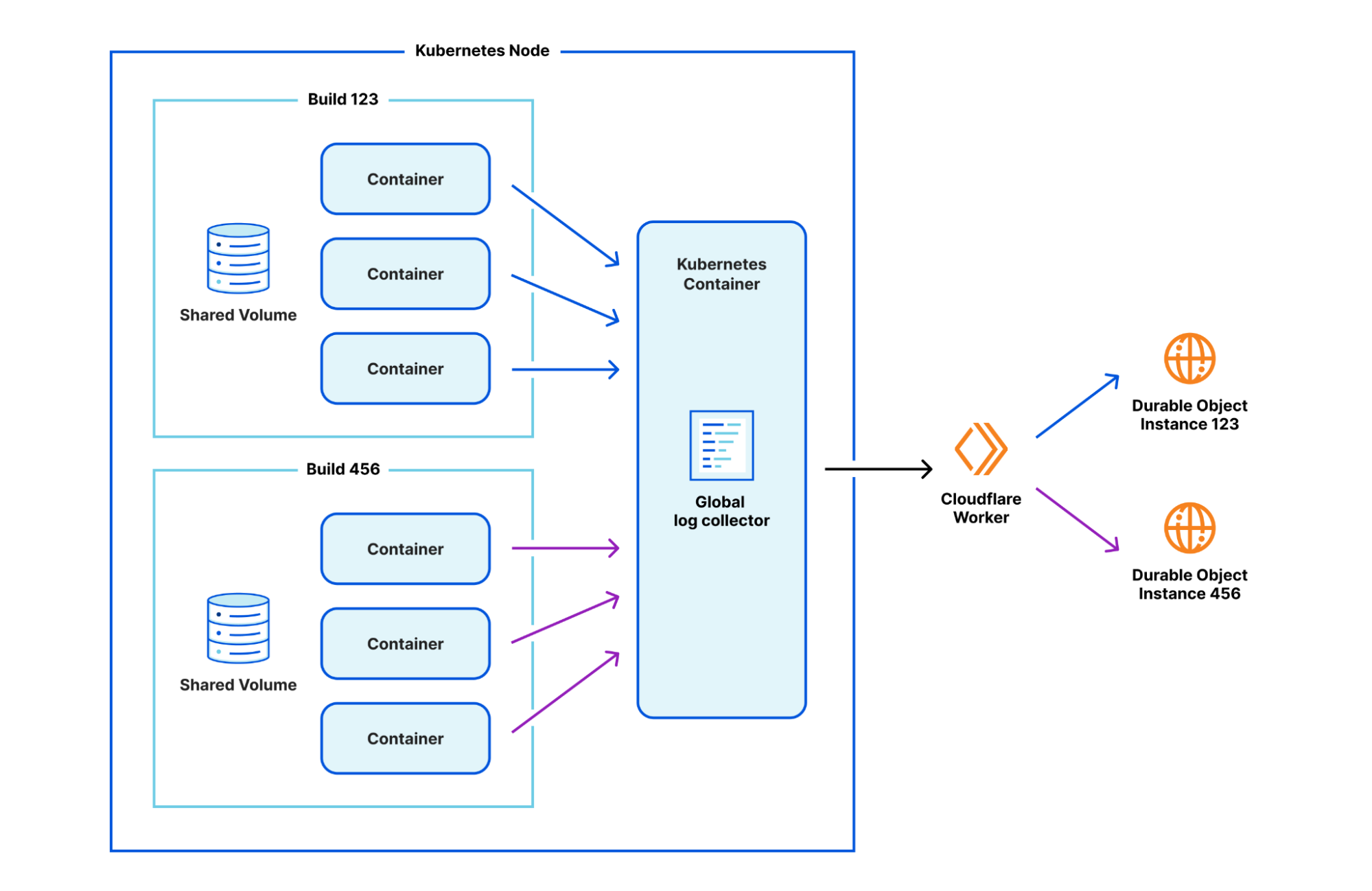
By introducing this new isolation between containers, we had to get a bit more inventive. After prototyping a number of approaches, we've found one that we like. We run a separate, global log collector container inside Kubernetes which is responsible for collating logs from a build, and passing them through to that same Durable Object infrastructure. The one caveat is that the logs now need to be annotated with which build they are coming from, since one global log collector container accepts logs from multiple builds. A Worker in front of the Durable Object is responsible for reading the annotation and delegating to the relevant build's Durable Object instance.
Caching in
With this new modular architecture, we plan to integrate a feature we've been teasing for a while: build caching. Today, when you run a build in Cloudflare Pages, we start fresh every time. This works, but it's inefficient.
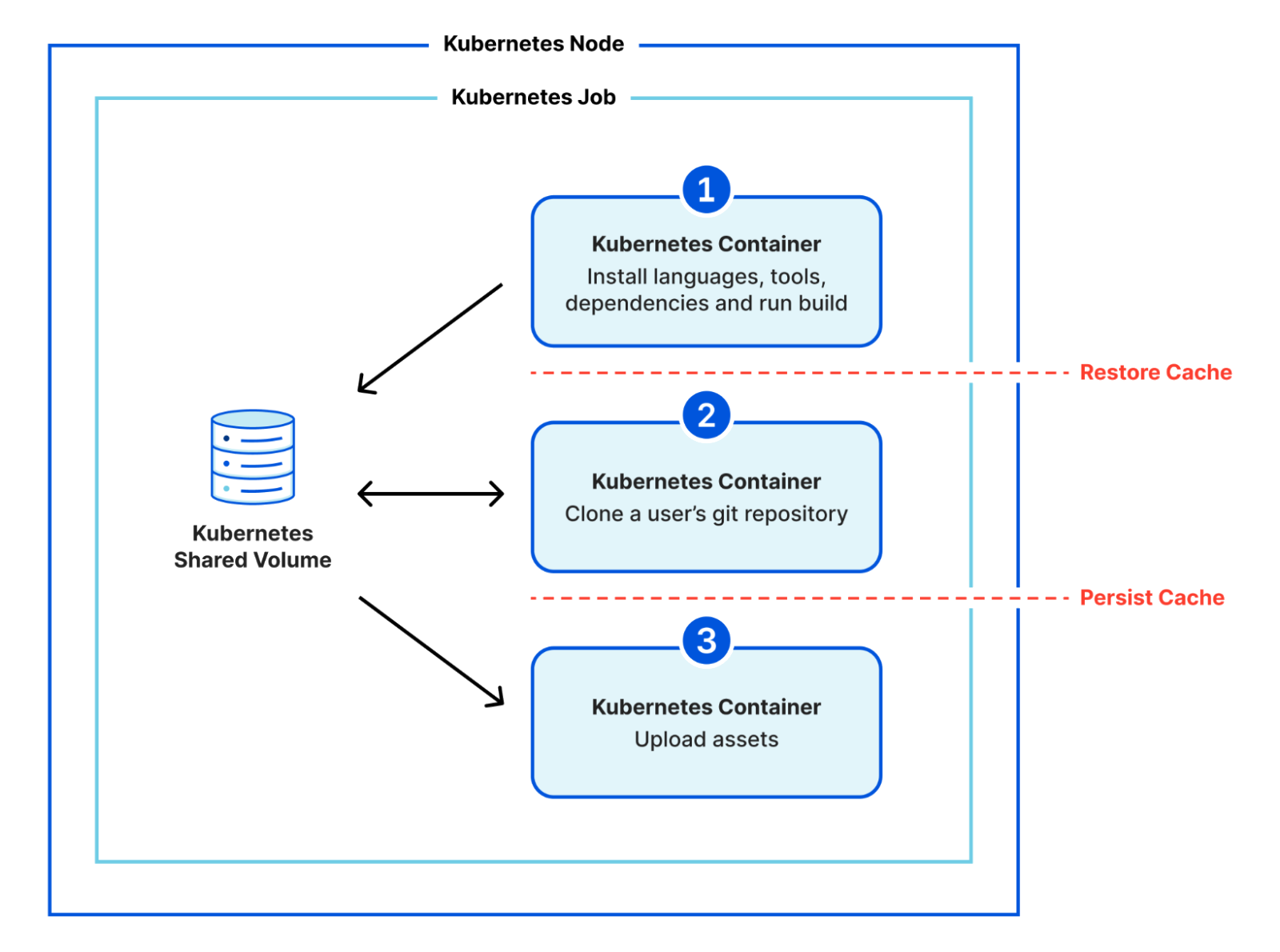
Very often, only small changes are actually made to your website between deployments: you might tweak some text on your homepage, or add a new blog post; but rarely does the core foundation of your site actually change between deployments. With build caching, we can reuse some of the work from earlier builds to speed up subsequent builds. We'll offer a best-effort storage mechanism that allows you to persist and restore files between builds. You'll soon be able to cache dependencies, as well as the build output itself if your framework supports it, resulting in considerably faster builds and a tighter feedback loop from push to deploy.
This is possible because our new modular design has clear divides between the stages where we'd want to restore and cache files.
Start building
We're excited about the improvements that this new modular architecture will afford the Pages team, but we're even more excited for how this will result in faster and more scalable builds for our users. This architecture transition is rolling out behind-the-scenes, but the updated beta build system with new languages and tools is available to try today. Navigate to your Pages project settings in the Cloudflare Dashboard to opt-in.
Let us know if you have any feedback on the Discord server, and stay tuned for more information about build caching in upcoming posts on this blog. Later today (Wednesday 17th, 2023), the Pages team will be hosting a Q&A session to talk about this announcement on Discord at 17:30 UTC.
For over a year now, we’ve been working to improve the Workers local development experience. Our goal has been to improve parity between users' local and production environments. This is important because it provides developers with a fully-controllable and easy-to-debug local testing environment, which leads to increased developer efficiency and confidence.
To start, we integrated Miniflare, a fully-local simulator for Workers, directly into Wrangler, the Workers CLI. This allowed users to develop locally with Wrangler by running wrangler dev --local. Compared to the wrangler dev default, which relied on remote resources, this represented a significant step forward in local development. As good as it was, it couldn’t leverage the actual Workers runtime, which led to some inconsistencies and behavior mismatches.
Last November, we announced the experimental version of Miniflare v3, powered by the newly open-sourced workerd runtime, the same runtime used by Cloudflare Workers. Since then, we’ve continued to improve upon that experience both in terms of accuracy with the real runtime and in cross-platform compatibility.
As a result of all this work, we are proud to announce the release of Wrangler v3 – the first version of Wrangler with local-by-default development.
A new default for Wrangler
Starting with Wrangler v3, users running wrangler dev will be leveraging Miniflare v3 to run your Worker locally. This local development environment is effectively as accurate as a production Workers environment, providing an ability for you to test every aspect of your application before deploying. It provides the same runtime and bindings, but has its own simulators for KV, R2, D1, Cache and Queues. Because you’re running everything on your machine, you won’t be billed for operations on KV namespaces or R2 buckets during development, and you can try out paid-features like Durable Objects for free.
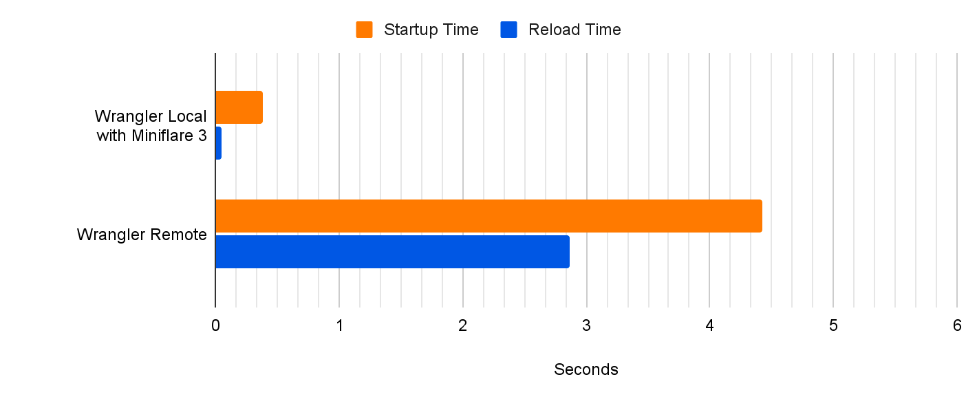
In addition to a more accurate developer experience, you should notice performance differences. Compared to remote mode, we’re seeing a 10x reduction to startup times and 60x reduction to script reload times with the new local-first implementation. This massive reduction in reload times drastically improves developer velocity!
Remote development isn’t going anywhere. We recognise many developers still prefer to test against real data, or want to test Cloudflare services like image resizing that aren’t implemented locally yet. To run wrangler dev on Cloudflare’s network, just like previous versions, use the new --remote flag.
Deprecating Miniflare v2
For users of Miniflare, there are two important pieces of information for those updating from v2 to v3. First, if you’ve been using Miniflare’s CLI directly, you’ll need to switch to wrangler dev. Miniflare v3 no longer includes a CLI. Secondly, if you’re using Miniflare’s API directly, upgrade to miniflare@3 and follow the migration guide.
How we built Miniflare v3
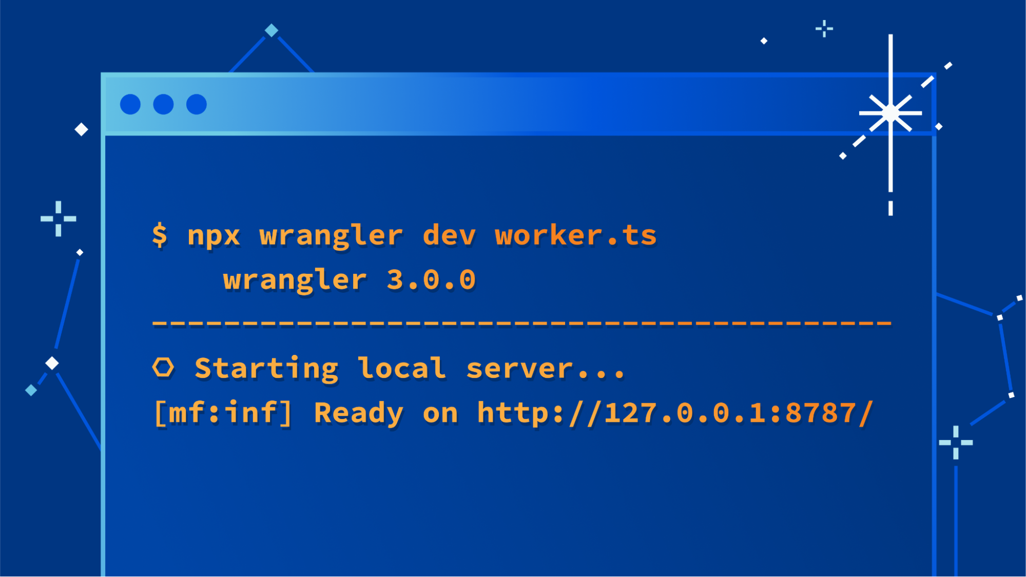
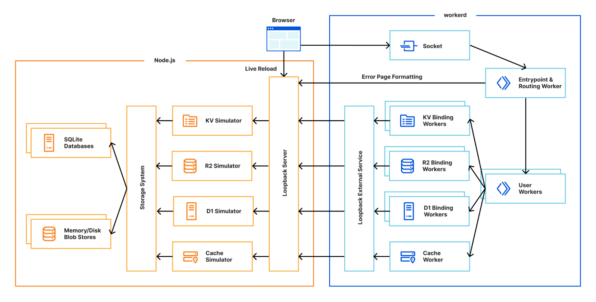
Miniflare v3 is now built using workerd, the open-source Cloudflare Workers runtime. As workerd is a server-first runtime, every configuration defines at least one socket to listen on. Each socket is configured with a service, which can be an external server, disk directory or most importantly for us, a Worker! To start a workerd server running a Worker, create a worker.capnp file as shown below, run npx workerd serve worker.capnp and visit http://localhost:8080 in your browser:
If you’re interested in what else workerd can do, check out the other samples. Whilst workerd provides the runtime and bindings, it doesn’t provide the underlying implementations for the other products in the Developer Platform. This is where Miniflare comes in! It provides simulators for KV, R2, D1, Queues and the Cache API.
Building a flexible storage system
As you can see from the diagram above, most of Miniflare’s job is now providing different interfaces for data storage. In Miniflare v2, we used a custom key-value store to back these, but this had afewlimitations. For Miniflare v3, we’re now using the industry-standard SQLite, with a separate blob store for KV values, R2 objects, and cached responses. Using SQLite gives us much more flexibility in the queries we can run, allowing us to support future unreleased storage solutions. 👀
A separate blob store allows us to provide efficient, ranged, streamed access to data. Blobs have unguessable identifiers, can be deleted, but are otherwise immutable. These properties make it possible to perform atomic updates with the SQLite database. No other operations can interact with the blob until it's committed to SQLite, because the ID is not guessable, and we don't allow listing blobs. For more details on the rationale behind this, check out the original GitHub discussion.
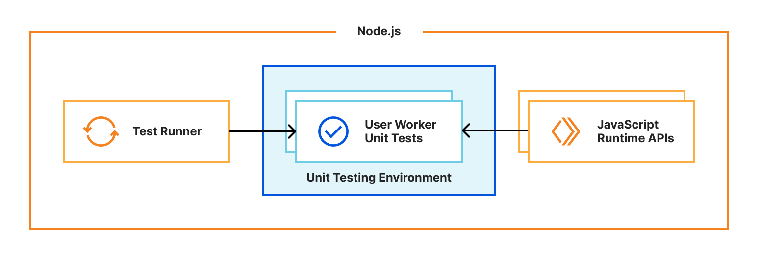
Running unit tests inside Workers
One of Miniflare’s primary goals is to provide a great local testing experience. Miniflare v2 provided custom environments for popular Node.js testing frameworks that allowed you to run your tests inside the Miniflare sandbox. This meant you could import and call any function using Workers runtime APIs in your tests. You weren’t restricted to integration tests that just send and receive HTTP requests. In addition, these environments provide per-test isolated storage, automatically undoing any changes made at the end of each test.
In Miniflare v2, these environments were relatively simple to implement. We’d already reimplemented Workers Runtime APIs in a Node.js environment, and could inject them using Jest and Vitest’s APIs into the global scope.
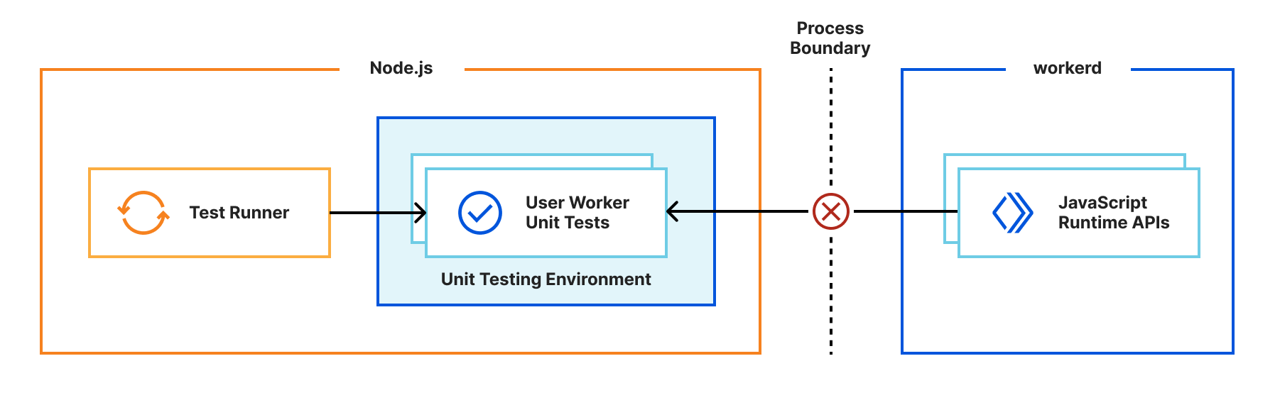
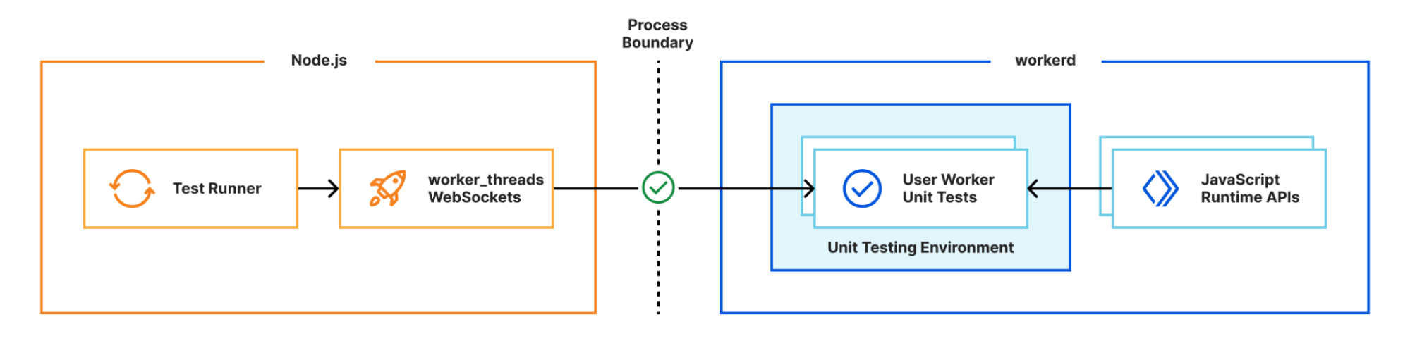
For Miniflare v3, this is much trickier. The runtime APIs are implemented in a separate workerd process, and you can’t reference JavaScript classes across a process boundary. So we needed a new approach…
Many test frameworks like Vitest use Node’s built-in worker_threads module for running tests in parallel. This module spawns new operating system threads running Node.js and provides a MessageChannel interface for communicating between them. What if instead of spawning a new OS thread, we spawned a new workerd process, and used WebSockets for communication between the Node.js host process and the workerd “thread”?
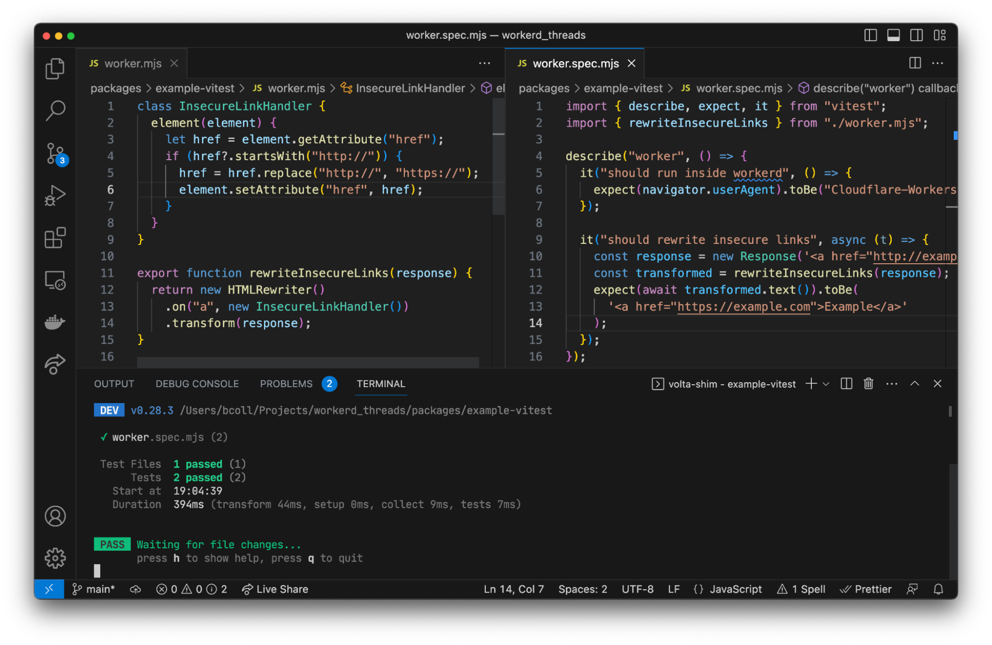
We have a proof of concept using Vitest showing this approach can work in practice. Existing Vitest IDE integrations and the Vitest UI continue to work without any additional work. We aren’t quite ready to release this yet, but will be working on improving it over the next few months. Importantly, the workerd “thread” needs access to Node.js built-in modules, which we recently started rolling out support for.
Running on every platform
We want developers to have this great local testing experience, regardless of which operating system they’re using. Before open-sourcing, the Cloudflare Workers runtime was originally only designed to run on Linux. For Miniflare v3, we needed to add support for macOS and Windows too. macOS and Linux are both Unix-based, making porting between them relatively straightforward. Windows on the other hand is an entirely different beast… 😬
The workerd runtime uses KJ, an alternative C++ base library, which is already cross-platform. We’d also migrated to the Bazel build system in preparation for open-sourcing the runtime, which has good Windows support. When compiling our C++ code for Windows, we use LLVM's MSVC-compatible compiler driver clang-cl, as opposed to using Microsoft’s Visual C++ compiler directly. This enables us to use the "same" compiler frontend on Linux, macOS, and Windows, massively reducing the effort required to compile workerd on Windows. Notably, this provides proper support for #pragma once when using symlinked virtual includes produced by Bazel, __atomic_* functions, a standards-compliant preprocessor, GNU statement expressions used by some KJ macros, and understanding of the .c++ extension by default. After switching out unix API calls for their Windows equivalents using #if _WIN32 preprocessor directives, and fixing a bunch of segmentation faults caused by execution order differences, we were finally able to get workerd running on Windows! No WSL or Docker required! 🎉
Let us know what you think!
Wrangler v3 is now generally available! Upgrade by running npm install --save-dev wrangler@3 in your project. Then run npx wrangler dev to try out the new local development experience powered by Miniflare v3 and the open-source Workers runtime. Let us know what you think in the #wrangler channel on the Cloudflare Developers Discord, and please open a GitHub issue if you hit any unexpected behavior.
One of the best feelings as a developer is seeing your idea come to life. You want to move fast and Cloudflare’s developer platform gives you the tools to take your applications from 0 to 100 within minutes.
One thing that we’ve heard slows developers down is the question: “What databases can be used with Workers?”. Developers stumble when it comes to things like finding the databases that Workers can connect to, the right library or driver that's compatible with Workers and translating boilerplate examples to something that can run on our developer platform.
Today we’re announcing Database Integrations – making it seamless to connect to your database of choice on Workers. To start, we’ve added some of the most popular databases that support HTTP connections: Neon, PlanetScale and Supabase with more (like Prisma, Fauna, MongoDB Atlas) to come!
Focus more on code, less on config
Our serverless SQL database, D1, launched in open alpha last year, and we’re continuing to invest in making it production ready (stay tuned for an exciting update later this week!). We also recognize that there are plenty of flavours of databases, and we want developers to have the freedom to select what’s best for them and pair it with our powerful compute offering.
On our second day of this Developer Week 2023, data is in the spotlight. We’re taking huge strides in making it possible and more performant to connect to databases from Workers (spoiler alert!):
Making it possible and performant is just the start, we also want to make connecting to databases painless. Databases have specific protocols, drivers, APIs and vendor specific features that you need to understand in order to get up and running. With Database Integrations, we want to make this process foolproof.
Whether you’re working on your first project or your hundredth project, you should be able to connect to your database of choice with your eyes closed. With Database Integrations, you can spend less time focusing on configuration and more on doing what you love – building your applications!
What does this experience look like?
Discoverability
If you’re starting a project from scratch or want to connect Workers to an existing database, you want to know “What are my options?”.
Workers supports connections to a wide array of database providers over HTTP. With newly released outbound TCP support, the databases that you can connect to on Workers will only grow!
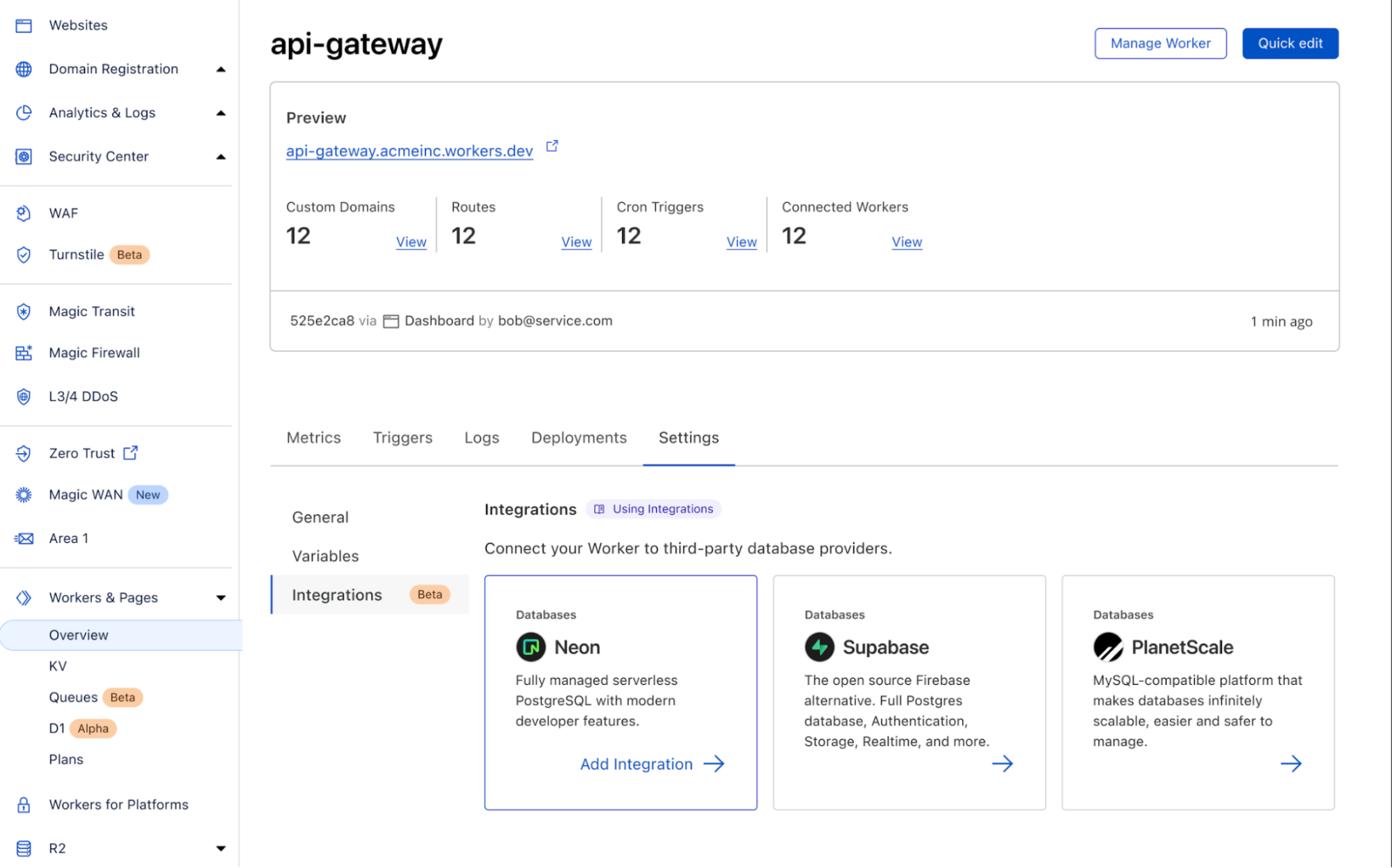
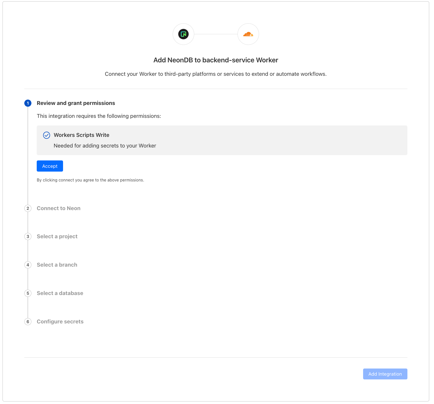
In the new “Integrations” tab, you’ll be able to view all the databases that we support and add the integration to your Worker directly from here. To start, we have support for Neon, PlanetScale and Supabase with many more coming soon.
Authentication
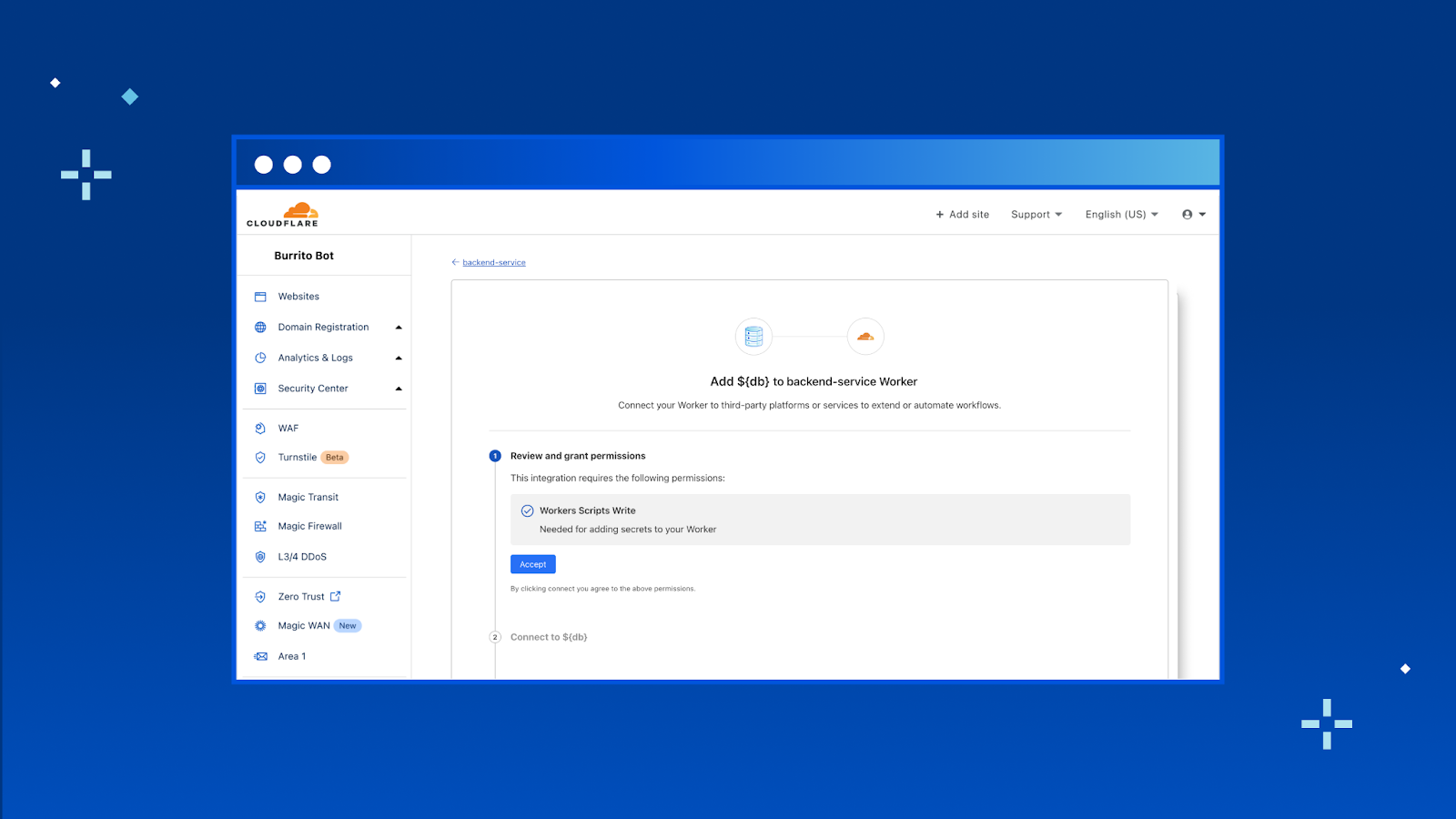
You should never have to copy and paste your database credentials or other parts of the connection string.
Once you hit “Add Integration” we take you through an OAuth2 flow that automatically gets the right configuration from your database provider and adds them as encrypted environment variables to your Worker.
Once you have credentials set up, check out our documentation for examples on how to get started using the data platform’s client library. What’s more – we have templates coming that will allow you to get started even faster!
That’s it! With database integrations, you can connect your Worker with your database in just a few clicks. Head to your Worker > Settings > Integrations to try it out today.
What’s next?
We’ve only just scratched the surface with Database Integrations and there’s a ton more coming soon!
While we’ll be continuing to add support for more popular data platforms we also know that it's impossible for us to keep up in a moving landscape. We’ve been working on an integrations platform so that any database provider can easily build their own integration with Workers. As a developer, this means that you can start tinkering with the next new database right away on Workers.
Additionally, we’re working on adding wrangler support, so you can create integrations directly from the CLI. We’ll also be adding support for account level environment variables in order for you to share integrations across the Workers in your account.
We’re really excited about the potential here and to see all the new creations from our developers! Be sure to join Cloudflare’s Developer Discord and share your projects. Happy building!
It is an incredibly exciting time to be a developer.
The frameworks, libraries and developer tools we depend on keep leveling up in ways that allow us to build more efficiently. On top of that, we’re using AI-powered tools like ChatGPT and GitHub Copilot to ship code quicker than many of us ever could have imagined. This all means we’re spending less time on boilerplate code and setup, and more time writing the code that makes our applications unique.
It’s not only a time when we’re equipped with the tools to be successful in new ways, but we're also finding inspiration in what’s happening around us. It feels like every day there’s an advancement with AI that changes the boundaries of what we can build. Across meetups, conferences, chat rooms, and every other place we gather as developers, we’re pushing each other to expand our ideas of what is possible.
With so much excitement permeating through the global developer community, we couldn’t imagine a better time to be kicking off Developer Week here at Cloudflare.
A focus on developer experience
A big part of any Innovation Week at Cloudflare is bringing you all new products to play with. And this year will be no different, there will be plenty of new products coming your way over the next seven days, and we can’t wait for you to get your hands on them. But we know that for developers it can sometimes be more exciting to see a tool you already use upgrade its developer experience than to get something new. That’s why as we’ve planned for this Developer Week we have been particularly focused on how we can make our developer experience more seamless by addressing many of your most requested features & fixes.
Part of making our developer experience more seamless is ensuring you all can bring the technologies you already know and love to Cloudflare. We’ve especially heard this from you all when it comes to deploying JAMstack applications on Cloudflare. Without spoiling too much, if you’re using a frontend framework and building JAMstack applications we’re excited about what we’re shipping for you this week.
A platform born in the Age of AI
We want developers to be able to build anything they’re excited about on Cloudflare. And one thing a lot of us are excited about right now are AI applications. AI is something that’s been part of Cloudflare’s foundation since the beginning. We are a company that was born in the age of AI. A core part of how we work towards our mission to help build a better Internet is by using machine learning to help protect your applications.
Through this week, we want to empower you with the tools and wisdom we’ve gathered around AI and machine learning. As well as showing you how to use Cloudflare with some of your new favorite AI developer tools. We’ll be shipping sample code, tutorials, tips and best practices. And that wisdom won’t only be coming from us, we’ll be sharing the stories of customers who have built on us and give you all an opportunity to learn from the companies that inspire us.
Why I joined Cloudflare
This is special Developer Week for me because it’s my first Developer Week at Cloudflare. I joined a little over a month ago to lead our Developer Relations & Community team.
When I found out I was joining Cloudflare I called up one of my closest friends, and mentors, to share the news. He immediately said “What are you going to do? Developers are all already using Cloudflare. No matter how big or small of a project I build, I always use Cloudflare. It’s the last thing I set up before I deploy.” He couldn’t have set the stage better for me to share why I’m excited to join and a theme you’ll see throughout this week.
For many developers, you know us for our CDN, and we are one of the last pieces of infrastructure you set up for your project. Since we launched Cloudflare Workers in 2017, we’ve been shipping tools intended to help empower you not only at the end of your journey, but from the moment you start building a new project. Myself, and my team, are here to help you discover and be successful with all of our developers tools. We’ll be here from the moment you start building, when you go into production and all the way through when you’re scaling your application to millions of users around the world.
Whether you are one of the over one million developers already building on Cloudflare or you’re starting to use us for the first time during this Developer Week, I can’t wait to meet you.
Welcome to Developer Week 2023
We’re excited to kick off another Developer Week. Through this week we’ll tell you about the new tools we’re shipping and share how many of them were built. We’ll show you how you can use them, and share stories from customers who are using our developer platform today. We hope you’ll be part of the conversation, whether that’s on discord, Cloudflare TV, community.cloudflare.com, or social media.
Join us on Wednesday, May 17, for AWS Serverless Innovation Day, a free full-day virtual event. You will learn about AWS Serverless technologies and event-driven architectures from customers, experts, and leaders.
AWS Serverless Innovation Day is an event to empower builders and technical decision-makers with different AWS Serverless technologies, including AWS Lambda, Amazon Elastic Container Service (Amazon ECS) with AWS Fargate, Amazon EventBridge, and AWS Step Functions. The talks of the day will cover three key topics: event-driven architectures, serverless containers, and serverless functions, and how they can be utilized to build and modernize applications. Application modernization is a priority for organizations this year, and serverless helps to increase the software delivery speed and reduce the total cost of ownership.
Eric Johnson and Jessica Deen will be the hosts for the event. Holly Mesrobian, VP of Serverless Compute at AWS, will deliver the welcome keynote and share AWS’s vision for Serverless. The day ends with closing remarks from James Beswick and Usman Khalid, Events and Workflows Director at AWS.
The event is split into three groups of talks: event-driven architecture, serverless containers, and Lambda-based applications. Each group kicks off with a fireside chat between AWS customers and an AWS leader. You can learn how organizations, such as Capital One, PostNL, Pentasoft, Delta Air Lines, and Smartsheets, are using AWS Serverless technologies to solve their most challenging problems and continue to innovate.
During the day, all the sessions include demos and use cases, where you can learn the best practices and how to build applications. If you cannot attend all day, here are some of my favorite sessions to watch:
Building with serverless workflows at scale – Ben Smith will show you how to unleash the power of AWS Step Functions.
Event design and event-first development – In this session, David Boyne will show you a robust approach to event design with Amazon EventBridge.
Best practices for AWS Lambda – You will learn from Julian Wood how to get the most out of your functions.
Optimizing for cost using Amazon ECS – Scott Coulton will show you how to reduce operational overhead from the control plane with Amazon ECS.
There is no up-front registration required to join the AWS Serverless Innovation Day, but if you want to be notified before the event starts, get in-depth news, articles, and event updates, and get a notification when the on-demand videos are available, you can register on the event page. The event will be streamed on Twitch, LinkedIn Live, YouTube, and Twitter.
Today, we're open-sourcing our ChatGPT Plugin Quickstart repository for Cloudflare Workers, designed to help you build awesome and versatile plugins for ChatGPT with ease. If you don’t already know, ChatGPT is a conversational AI model from OpenAI which has an uncanny ability to take chat input and generate human-like text responses.
With the recent addition of ChatGPT plugins, developers can create custom extensions and integrations to make ChatGPT even more powerful. Developers can now provide custom flows for ChatGPT to integrate into its conversational workflow – for instance, the ability to look up products when asking questions about shopping, or retrieving information from an API in order to have up-to-date data when working through a problem.
That's why we're super excited to contribute to the growth of ChatGPT plugins with our new Quickstart template. Our goal is to make it possible to build and deploy a new ChatGPT plugin to production in minutes, so developers can focus on creating incredible conversational experiences tailored to their specific needs.
How it works
Our Quickstart is designed to work seamlessly with Cloudflare Workers. Under the hood, it uses our command-line tool wrangler to create a new project and deploy it to Workers.
When building a ChatGPT plugin, there are three things you need to consider:
The plugin's metadata, which includes the plugin's name, description, and other info
The plugin's schema, which defines the plugin's input and output
The plugin's behavior, which defines how the plugin responds to user input
To handle all of these parts in a simple, easy-to-understand API, we've created the @cloudflare/itty-router-openapi package, which makes it easy to manage your plugin's metadata, schema, and behavior. This package is included in the ChatGPT Plugin Quickstart, so you can get started right away.
To show how the package works, we'll look at two key files in the ChatGPT Plugin Quickstart: index.js and search.js. The index.js file contains the plugin's metadata and schema, while the search.js file contains the plugin's behavior. Let's take a look at each of these files in more detail.
In index.js, we define the plugin's metadata and schema. The metadata includes the plugin's name, description, and version, while the schema defines the plugin's input and output.
The configuration matches the definition required by OpenAI's plugin manifest, and helps ChatGPT understand what your plugin is, and what purpose it serves.
Here's what the index.js file looks like:
import { OpenAPIRouter } from "@cloudflare/itty-router-openapi";
import { GetSearch } from "./search";

export const router = OpenAPIRouter({
  schema: {
    info: {
      title: 'GitHub Repositories Search API',
      description: 'A plugin that allows the user to search for GitHub repositories using ChatGPT',
      version: 'v0.0.1',
    },
  },
  docs_url: '/',
  aiPlugin: {
    name_for_human: 'GitHub Repositories Search',
    name_for_model: 'github_repositories_search',
    description_for_human: "GitHub Repositories Search plugin for ChatGPT.",
    description_for_model: "GitHub Repositories Search plugin for ChatGPT. You can search for GitHub repositories using this plugin.",
    contact_email: '[email protected]',
    legal_info_url: 'http://www.example.com/legal',
    logo_url: 'https://workers.cloudflare.com/resources/logo/logo.svg',
  },
})

router.get('/search', GetSearch)

// 404 for everything else
router.all('*', () => new Response('Not Found.', { status: 404 }))

export default {
  fetch: router.handle
}
In the search.js file, we define the plugin's behavior. This is where we define how the plugin responds to user input. It also defines the plugin's schema, which ChatGPT uses to validate the plugin's input and output.
Importantly, this doesn't just define the implementation of the code. It also automatically generates an OpenAPI schema that helps ChatGPT understand how your code works — for instance, that it takes a parameter "q", that it is of "String" type, and that it can be described as "The query to search for". With the schema defined, the handle function makes any relevant parameters available as function arguments, to implement the logic of the endpoint as you see fit.
The quickstart smooths out the entire development process, so you can focus on crafting custom behaviors, endpoints, and features for your ChatGPT plugins without getting caught up in the nitty-gritty. If you aren't familiar with API schemas, this also means that you can rely on our schema and manifest generation tools to handle the complicated bits, and focus on the implementation to build your plugin.
Besides making development a breeze, it's worth noting that you're also deploying to Workers, which takes advantage of Cloudflare's vast global network. This means your ChatGPT plugins enjoy low-latency access and top-notch performance, no matter where your users are located. By combining the strengths of Cloudflare Workers with the versatility of ChatGPT plugins, you can create conversational AI tools that are not only powerful and scalable but also cost-effective and globally accessible.
Example
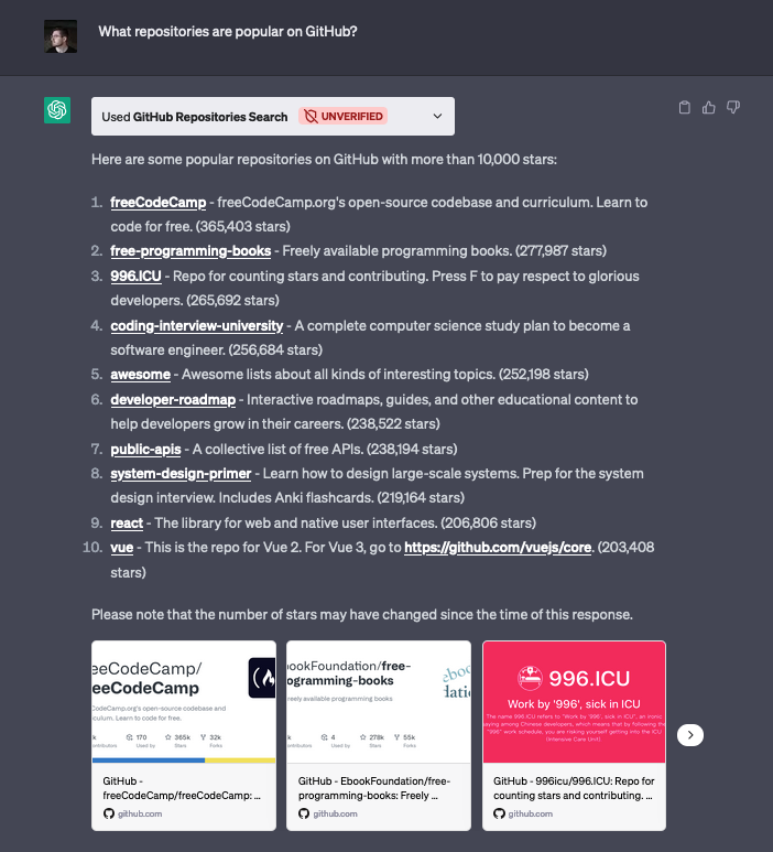
To demonstrate the capabilities of our quickstarts, we've created two example ChatGPT plugins. The first, which we reviewed above, connects ChatGPT with the GitHub Repositories Search API. This plugin enables users to search for repositories by simply entering a search term, returning useful information such as the repository's name, description, star count, and URL.
One intriguing aspect of this example is the property where the plugin could go beyond basic querying. For instance, when asked "What are the most popular JavaScript projects?", ChatGPT was able to intuitively understand the user's intent and craft a new query parameter for querying both by the number of stars (measuring popularity), and the specific programming language (JavaScript) without requiring any explicit prompting. This showcases the power and adaptability of ChatGPT plugins when integrated with external APIs, providing more insightful and context-aware responses.
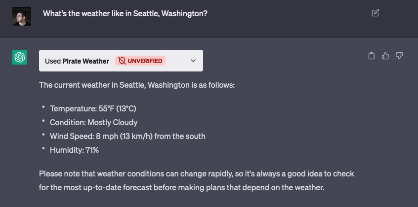
The second plugin uses the Pirate Weather API to retrieve up-to-date weather information. Remarkably, OpenAI is able to translate the request for a specific location (for instance, “Seattle, Washington”) into longitude and latitude values – which the Pirate Weather API uses for lookups – and make the correct API request, without the user needing to do any additional work.
With our ChatGPT Plugin Quickstarts, you can create custom plugins that connect to any API, database, or other data source, giving you the power to create ChatGPT plugins that are as unique and versatile as your imagination. The possibilities are endless, opening up a whole new world of conversational AI experiences tailored to specific domains and use cases.
Get started today
The ChatGPT Plugin Quickstarts don’t just make development a snap—it also offers seamless deployment and scaling thanks to Cloudflare Workers. With the generous free plan provided by Workers, you can deploy your plugin quickly and scale it infinitely as needed.
Our ChatGPT Plugin Quickstarts are all about sparking creativity, speeding up development, and empowering developers to create amazing conversational AI experiences. By leveraging Cloudflare Workers' robust infrastructure and our streamlined tooling, you can easily build, deploy, and scale custom ChatGPT plugins, unlocking a world of endless possibilities for conversational AI applications.
Whether you're crafting a virtual assistant, a customer support bot, a language translator, or any other conversational AI tool, our ChatGPT Plugin Quickstarts are a great place to start. We're excited to provide this Quickstart, and would love to see what you build with it. Join us in our Discord community to share what you're working on!
This was written by Uma Ramadoss, Specialist Integration Services, and Chandan Rupakheti, Solutions Architect.
This blog post shows how you can save cost by automating the stopping and starting of an Amazon Managed Workflows for Apache Airflow (Amazon MWAA) environment. It describes how you can retain the data stored in a metadata database and presents an automated solution you can use in your AWS account.
Customers run end to end data pipelines at scale with MWAA. It is a common best practice to run non-production environments for development and testing. A nonproduction environment often does not need to run throughout the day due to factors such as working hours of the development team. As there is no automatic way to stop an MWAA environment when not in use and deleting an environment causes metadata loss, customers often run it continually and pay the full cost.
Overview
Amazon MWAA has a distributed architecture with multiple components such as scheduler, worker, webserver, queue, and database. Customers build data pipelines as Directed Acyclic Graphs (DAGs) and run in Amazon MWAA. The DAGs use variables and connections from the Amazon MWAA metadata database. The history of DAG runs and related data are stored in the same metadata database. The database also stores other information such as user roles and permissions.
When you delete the Amazon MWAA environment, all the components including the database are deleted so that you do not incur any cost. As this normal deletion results in loss of metadata, you need a customized solution to back up the data and to automate the deletion and recreation.
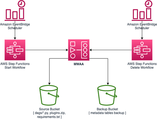
The sample application deletes and recreates your MWAA environment at a scheduled interval defined by you using Amazon EventBridge Scheduler. It exports all metadata into an Amazon S3 bucket before deletion and imports the metadata back to the environment after creation. As this is a managed database and you cannot access the database outside the Amazon MWAA environment, it uses DAGs to import and export the data. The entire process is orchestrated using AWS Step Functions.
Deployment architecture
The sample application is in a GitHub repository. Use the instructions in the readme to deploy the application.
The sample application deploys the following resources –
A Step Functions state machine to orchestrate the steps needed to delete the MWAA environment.
A Step Functions state machine to orchestrate the steps needed to recreate the MWAA environment.
EventBridge Scheduler rules to trigger the state machines at the scheduled time.
An S3 bucket to store metadata database backup and environment details.
Two DAG files uploaded to the source S3 bucket configured with the MWAA environment. The export DAG exports metadata from the MWAA metadata database to backup S3 bucket. The import DAG restores the metadata from the backup S3 bucket to the newly created MWAA environment.
AWS Lambda functions for triggering the DAGs using MWAA CLI API.
A Step Functions state machine to wait for the long-running MWAA creation and deletion process.
At a scheduled time, Amazon EventBridge Scheduler triggers a Step Functions state machine to stop the MWAA environment. The state machine performs the following actions:
Fetch Amazon MWAA environment details such as airflow configurations, IAM execution role, logging configurations and VPC details.
If the environment is not in the “AVAILABLE” status, it fails the workflow by branching to the “Pausing unsuccessful” state.
Otherwise, it runs the normal workflow and stores the environment details in an S3 bucket so that Start workflow can recreate the environment with this data.
Trigger an MWAA DAG using AWS Lambda function to export metadata to the Amazon S3 bucket. This step uses Step Functions to wait for callback token integration.
Resume the workflow when the task token is returned from the MWAA DAG.
Delete Amazon MWAA environment.
Wait to confirm the deletion.
Start workflow
At a scheduled time, EventBridge Scheduler triggers the Step Functions state machine to recreate the MWAA environment. The steps in the state machine perform the following actions:
Retrieve the environment details stored in Amazon S3 bucket by the stop workflow.
Create an MWAA environment with the same configuration as the original.
Trigger an MWAA DAG through the Lambda function to restore the metadata from the S3 bucket to the newly created environment.
Cost savings
Consider a small MWAA environment in us-east-2 with a minimum of one worker, a maximum of one worker, and 1GB data storage. At the time of this writing, the monthly cost of the environment is $357.80. Let’s assume you use this environment between 6 am and 6 pm on weekdays.
The schedule in the env file of the sample application looks like:
The sample application only restores at-store data. Though the deletion process pauses all the DAGs before making the backup, it cannot stop any running tasks or in-flight messages in the queue. It also does not backup tasks that are not in completed state. This can result in task history loss for the tasks that were running during the backup.
Over time, the metadata grows in size, which can increase latency in query performance. You can use a DAG as shown in the example to clean up the database regularly.
Avoid setting the catchup by default configuration flag in the environment setting to true or in the DAG definition unless it is required. Catch up feature runs all the DAG runs that are missed for any data interval. When the environment is created again, if the flag is true, it catches up with the missed DAG runs and can overload the environment.
Conclusion
Automating the deletion and recreation of Amazon MWAA environments is a powerful solution for cost optimization and efficient management of resources. By following the steps outlined in this blog post, you can ensure that your MWAA environment is deleted and recreated without losing any of the metadata or configurations. This allows you to deploy new code changes and updates more quickly and easily, without having to configure your environment each time manually.
The potential cost savings of running your MWAA environment for only 12 hours on weekdays are significant. The example shows how you can save up to 65% of your monthly costs by choosing this option. This makes it an attractive solution for organizations that are looking to reduce cost while maintaining a high level of performance.
Visit the samples repository to learn more about Amazon MWAA. It contains a wide variety of examples and templates that you can use to build your own applications.
For more serverless learning resources, visit Serverless Land.
This post is written by Daniel Lorch, Senior Consultant and David Mbonu, Senior Solutions Architect.
Amazon Simple Notification Service (Amazon SNS), a messaging service that provides high-throughput, push-based, many-to-many messaging between distributed systems, microservices, and event-driven serverless applications, now supports active tracing with AWS X-Ray.
With AWS X-Ray active tracing enabled for SNS, you can identify bottlenecks and monitor the health of event-driven applications by looking at segment details for SNS topics, such as resource metadata, faults, errors, and message delivery latency for each subscriber.
This blog post reviews common use cases where AWS X-Ray active tracing enabled for SNS provides a consistent view of tracing data across AWS services in real-world scenarios. We cover two architectural patterns which allow you to gain accurate visibility of your end-to-end tracing: SNS to Amazon Simple Queue Service (Amazon SQS) queues and SNS topics to Amazon Kinesis Data Firehose streams.
Getting started with the sample serverless application
To demonstrate AWS X-Ray active tracing for SNS, we will use the Wild Rydes serverless application as shown in the following figure. The application uses a microservices architecture which implements asynchronous messaging for integrating independent systems.
This is how the sample serverless application works:
An SNS topic serves as a fan-out for ride requests.
Individual SQS queues and Lambda functions are set up for processing requests via various back-office services (customer notification, customer accounting, and others).
An SNS message filter is in place for the subscription of the extraordinary rides service.
Validate that messages are being passed in the application using the CloudWatch service map:
See the sample application README.md for detailed testing instructions.
The sample application shows various use-cases, which are described in the following sections.
Amazon SNS to Amazon SQS fanout scenario
A common application integration scenario for SNS is the Fanout scenario. In the Fanout scenario, a message published to an SNS topic is replicated and pushed to multiple endpoints, such as SQS queues. This allows for parallel asynchronous processing and is a common application integration pattern used in event-driven application architectures.
When an SNS topic fans out to SQS queues, the pattern is called topic-queue-chaining. This means that you add a queue, in our case an SQS queue, between the SNS topic and each of the subscriber services. As messages are buffered in a persistent manner in an SQS queue, no message is lost should a subscriber process run into issues for multiple hours or days, or experience exceptions or crashes.
By placing an SQS queue in front of each subscriber service, you can leverage the fact that a queue can act as a buffering load balancer. As every queue message is delivered to one of potentially many consumer processes, subscriber services can be easily scaled out and in, and the message load is distributed over the available consumer processes. In an event where suddenly a large number of messages arrives, the number of consumer processes has to be scaled out to cope with the additional load. This takes time and you need to wait until additional processes become operational. Since messages are buffered in the queue, you do not lose any messages in the process.
To summarize, in the Fanout scenario or the topic-queue-chaining pattern:
SNS replicates and pushes the message to multiple endpoints.
SQS decouples sending and receiving endpoints.
With AWS X-Ray active tracing enabled on the SNS topic, the CloudWatch service map shows us the complete application architecture, as follows.
Prior to the introduction of AWS X-Ray active tracing on the SNS topic, the AWS X-Ray service would not be able to reconstruct the full service map and the SQS nodes would be missing from the diagram.
To see the integration without AWS X-Ray active tracing enabled, open template.yaml and navigate to the resource RideCompletionTopic. Comment out the property TracingConfig: Active, redeploy and test the solution. The service map should then show an incomplete diagram where the SNS topic is linked directly to the consumer Lambda functions, omitting the SQS nodes.
For this use case, given the Fanout scenario, enabling AWS X-Ray active tracing on the SNS topic provides full end-to-end observability of the traces available in the application.
Amazon SNS to Amazon Kinesis Data Firehose delivery streams for message archiving and analytics
SNS is commonly used with Kinesis Data Firehose delivery streams for message archival and analytics use-cases. You can use SNS topics with Kinesis Data Firehose subscriptions to capture, transform, buffer, compress and upload data to Amazon S3, Amazon Redshift, Amazon OpenSearch Service, HTTP endpoints, and third-party service providers.
We will implement this pattern as follows:
An SNS topic to replicate and push the message to its subscribers.
A Kinesis Data Firehose delivery stream to capture and buffer messages.
An S3 bucket to receive uploaded messages for archival.
In order to demonstrate this pattern, an additional consumer has been added to the SNS topic. The same Fanout pattern applies and the Kinesis Data Firehose delivery stream receives messages from the SNS topic alongside the existing consumers.
The Kinesis Data Firehose delivery stream buffers messages and is configured to deliver them to an S3 bucket for archival purposes. Optionally, an SNS message filter could be added to this subscription to select relevant messages for archival.
With AWS X-Ray active tracing enabled on the SNS topic, the Kinesis Data Firehose node will appear on the CloudWatch service map as a separate entity, as can be seen in the following figure. It is worth noting that the S3 bucket does not appear on the CloudWatch service map as Kinesis does not yet support AWS X-Ray active tracing at the time of writing of this blog post.
Prior to the introduction of AWS X-Ray active tracing on the SNS topic, the AWS X-Ray service would not be able to reconstruct the full service map and the Kinesis Data Firehose node would be missing from the diagram. To see the integration without AWS X-Ray active tracing enabled, open template.yaml and navigate to the resource RideCompletionTopic. Comment out the property TracingConfig: Active, redeploy and test the solution. The service map should then show an incomplete diagram where the Kinesis Data Firehose node is missing.
For this use case, given the data archival scenario with Kinesis Delivery Firehose, enabling AWS X-Ray active tracing on the SNS topic provides additional visibility on the Kinesis Data Firehose node in the CloudWatch service map.
Review faults, errors, and message delivery latency on the AWS X-Ray trace details page
The AWS X-Ray trace details page provides a timeline with resource metadata, faults, errors, and message delivery latency for each segment.
With AWS X-Ray active tracing enabled on SNS, additional segments for the SNS topic itself, but also the downstream consumers (AWS::SNS::Topic, AWS::SQS::Queue and AWS::KinesisFirehose) segments are available, providing additional faults, errors, and message delivery latency for these segments. This allows you to analyze latencies in your messages and their backend services. For example, how long a message spends in a topic, and how long it took to deliver the message to each of the topic’s subscriptions.
Enabling AWS X-Ray active tracing for SNS
AWS X-Ray active tracing is not enabled by default on SNS topics and needs to be explicitly enabled.
The example application used in this blog post demonstrates how to enable active tracing using AWS SAM.
To clean up the resources provisioned as part of the sample serverless application, follow the instructions as outlined in the sample application README.md.
Conclusion
AWS X-Ray active tracing for SNS enables end-to-end visibility in real-world scenarios involving patterns like SNS to SQS and SNS to Amazon Kinesis.
But it is not only useful for these patterns. With AWS X-Ray active tracing enabled for SNS, you can identify bottlenecks and monitor the health of event-driven applications by looking at segment details for SNS topics and consumers, such as resource metadata, faults, errors, and message delivery latency for each subscriber.
This post is written by Rahul Popat (Senior Solutions Architect) and Aneel Murari (Senior Solutions Architect)
Today, AWS X-Ray is announcing support for SnapStart-enabled AWS Lambda functions. Lambda SnapStart is a performance optimization that significantly improves the cold startup times for your functions. Announced at AWS re:Invent 2022, this feature delivers up to 10 times faster function startup times for latency-sensitive Java applications at no extra cost, and with minimal or no code changes.
X-Ray is a distributed tracing system that provides an end-to-end view of how an application is performing. X-Ray collects data about requests that your application serves and provides tools you can use to gain insight into opportunities for optimizations. Now you can use X-Ray to gain insights into the performance improvements of your SnapStart-enabled Lambda function.
With today’s feature launch, by turning on X-Ray tracing for SnapStart-enabled Lambda functions, you see separate subsegments corresponding to the Restore and Invoke phases for your Lambda function’s execution.
How does Lambda SnapStart work?
With SnapStart, the function’s initialization is done ahead of time when you publish a function version. Lambda takes an encrypted snapshot of the initialized execution environment and persists the snapshot in a tiered cache for low latency access.
When the function is first invoked or scaled, Lambda restores the cached execution environment from the persisted snapshot instead of initializing anew. This results in reduced startup times.
X-Ray tracing before this feature launch
Using an example of a Hello World application written in Java, a Lambda function is configured with SnapStart and fronted by Amazon API Gateway:
Before today’s launch, X-Ray was not supported for SnapStart-enabled Lambda functions. So if you had enabled X-Ray tracing for API Gateway, the X-Ray trace for the sample application would look like:
The trace only shows the overall duration of the Lambda service call. You do not have insight into your function’s execution or the breakdown of different phases of Lambda function lifecycle.
Next, enable X-Ray for your Lambda function and see how you can view a breakdown of your function’s total execution duration.
Prerequisites for enabling X-Ray for SnapStart-enabled Lambda function
SnapStart is only supported for Lambda functions with Java 11 and newly launched Java 17 managed runtimes. You can only enable SnapStart for the published versions of your Lambda function. Once you’ve enabled SnapStart, Lambda publishes all subsequent versions with snapshots. You may also create a Lambda function alias, which points to the published version of your Lambda function.
Make sure that the Lambda function’s execution role has appropriate permissions to write to X-Ray.
Enabling AWS X-Ray for your Lambda function with SnapStart
This blog shows how you can achieve this via AWS Management Console and AWS SAM. For more information on enabling SnapStart and X-Ray using other methods, refer to AWS Lambda Developer Guide.
Enabling SnapStart and X-Ray via AWS Management Console
On the Configuration tab, choose Edit and change the SnapStart attribute value from None to PublishedVersions.
Choose Save.
To enable X-Ray via the AWS Management Console:
Navigate to your Lambda Function.
On the Configuration tab, scroll down to the Monitoring and operations tools card and choose Edit.
Under AWS X-Ray, enable Active tracing.
Choose Save
To publish a new version of Lambda function via the AWS Management Console:
Navigate to your Lambda Function.
On the Version tab, choose Publish new version.
Verify that PublishedVersions is shown below SnapStart.
Choose Publish.
To create an alias for a published version of your Lambda function via the AWS Management Console:
Navigate to your Lambda Function.
On the Aliases tab, choose Create alias.
Provide a Name for an alias and select a Version of your Lambda function to point the alias to.
Choose Save.
Enabling SnapStart and X-Ray via AWS SAM
To enable SnapStart and X-Ray for Lambda function via AWS SAM:
Enable Lambda function versions and create an alias by adding a AutoPublishAlias property in template.yaml file. AWS SAM automatically publishes a new version for each new deployment and automatically assigns the alias to the newly published version.
Resources:
  my-function:
    type: AWS::Serverless::Function
    Properties:
      […]
      AutoPublishAlias: live
Enable SnapStart on Lambda function by adding the SnapStart property in template.yaml file.
Enable X-Ray for Lambda function by adding the Tracing property in template.yaml file.
Resources:
  my-function:
    type: AWS::Serverless::Function
    Properties:
      […]
      Tracing: Active
You can find the complete AWS SAM template for the preceding example in this GitHub repository.
Using X-Ray to gain insights into SnapStart-enabled Lambda function’s performance
To demonstrate X-Ray integration for your Lambda function with SnapStart, you can build, deploy, and test the sample Hello World application using AWS SAM CLI. To do this, follow the instructions in the README file of the GitHub project.
The build and deployment output with AWS SAM looks like this:
Once your application is deployed to your AWS account, note that SnapStart and X-Ray tracing is enabled for your Lambda function. You should also see an alias `live` created against the published version of your Lambda function.
You should also have an API deployed via API Gateway, which is pointing to the `live` alias of your Lambda function as the backend integration.
Now, invoke your API via `curl` command or any other HTTP client. Make sure to replace the url with your own API’s url.
$ curl --location --request GET https://{rest-api-id}.execute-api.{region}.amazonaws.com/{stage}/hello
Navigate to Amazon CloudWatch and under the X-Ray service map, you see a visual representation of the trace data generated by your application.
Under Traces, you can see the individual traces, Response code, Response time, Duration, and other useful metrics.
Select a trace ID to see the breakdown of total Duration on your API call.
You can now see the complete trace for the Lambda function’s invocation with breakdown of time taken during each phase. You can see the Restore duration and actual Invocation duration separately.
Restore duration shown in the trace includes the time it takes for Lambda to restore a snapshot on the microVM, load the runtime (JVM), and run any afterRestore hooks if specified in your code. Note that, the process of restoring snapshots can include time spent on activities outside the microVM. This time is not reported in the Restore sub-segment, but is part of the AWS::Lambda segment in X-Ray traces.
This helps you better understand the latency of your Lambda function’s execution, and enables you to identify and troubleshoot the performance issues and errors.
Conclusion
This blog post shows how you can enable AWS X-Ray for your Lambda function enabled with SnapStart, and measure the end-to-end performance of such functions using X-Ray console. You can now see a complete breakdown of your Lambda function’s execution time. This includes Restore duration along with the Invocation duration, which can help you to understand your application’s startup times (cold starts), diagnose slowdowns, or troubleshoot any errors and timeouts.
This post is written by Chetan Makvana, Sr. Solutions Architect.
Customers use modular architectural patterns and serverless operational models to build more sustainable, scalable, and resilient applications in modern application development. AWS Lambda is a popular choice for building these applications.
If customers have invested in container tooling for their development workflows, they deploy to Lambda using the container image packaging format for workloads like machine learning inference or data intensive workloads. Using functions deployed as container images, customers benefit from the same operation simplicity, automation scaling, high availability, and native integration with many services.
Containerized applications often have several distinct environments and accounts, such as dev, test, and prod. An application has to go through a process of deployment and testing in these environments. One common pattern for deploying containerized applications is to have a central AWS create a single container image, and carry out deployment across other AWS accounts. To achieve automated deployment of the application across different environments, customers use CI/CD pipelines with familiar container tooling.
This example comprises three accounts: tooling, test, and prod. The tooling account is a central account where you provision the pipeline, and build the container. The pipeline deploys the container into Lambda in the test and prod accounts using AWS CodeBuild. It also requires the necessary resources in the test and prod account. This consists of an Identity and Access Management (IAM) role that trusts the tooling account and provides the required deployment-specific permissions. AWS CodeBuild assumes this IAM role in the tooling account to carry out deployment.
AWS CodePipeline goes through these steps to deploy the container-based Lambda function in the test and prod accounts:
The developer commits the code of Lambda function into AWS CodeCommit or other source control repositories, which triggers the CI/CD workflow.
AWS CodeBuild builds the code, creates a container image, and pushes the image to the Amazon Elastic Container Registry (ECR) repository using AWS SAM.
AWS CodeBuild assumes a cross-account role for the test account.
AWS CodeBuild uses AWS SAM to deploy the Lambda function by pulling image from Amazon ECR.
If deployment is successful, AWS CodeBuild deploys the same image in prod account using AWS SAM.
Deploying the example
Prerequisites
An AWS account. The IAM user that you use must have sufficient permissions to make necessary AWS service calls and manage AWS resources.
cd ~/environment/cicd-lambda-container
git init -b main
git add .
git commit -m "Initial commit"
git remote add origin codecommit://lambda-container-repo
git push -u origin main
Creating cross-account roles in test and prod accounts
For the pipeline to gain access to the test and production environment, it must assume an IAM role. In cross-account scenario, the IAM role for the pipeline must be created on the test and production accounts.
Change directory to the directory templates and run the following command to deploy roles to test and prod using respective named profiles.
Test Profile
cd ~/environment/cicd-lambda-container/templates
aws cloudformation deploy --template-file crossaccount_pipeline_roles.yml --stack-name codepipeline-crossaccount-roles --capabilities CAPABILITY_NAMED_IAM --profile test --parameter-overrides ToolAccountID=${TOOLS_ACCOUNT_ID}
aws cloudformation describe-stacks --stack-name codepipeline-crossaccount-roles --query "Stacks[0].Outputs" --output json --profile test
Open the codepipeline_parameters.json file from the root directory. Replace the value of TestCodePipelineCrossAccountRoleArn and TestCloudFormationCrossAccountRoleArn with the CloudFormation output value of CodePipelineCrossAccountRole and CloudFormationCrossAccountRole respectively.
Open the codepipeline_parameters.json file from the root directory. Replace the value of ProdCodePipelineCrossAccountRoleArn and ProdCloudFormationCrossAccountRoleArn with the CloudFormation output value of CodePipelineCrossAccountRole and CloudFormationCrossAccountRole respectively.
Creating the required IAM roles and infrastructure in the tooling account
Change to the templates directory and run the following command using tooling named profile:
Open the codepipeline_parameters.json file from the root directory. Replace value of ImageRepositoryURI, ArtifactsBucket, ToolingCodePipelineExecutionRoleArn, and ToolingCloudFormationExecutionRoleArn with the corresponding CloudFormation output value.
Updating cross-account IAM roles
The cross-account IAM roles on the test and production account require permission to access artifacts that contain application code (S3 bucket and ECR repository). Note that the cross-account roles are deployed twice. This is because there is a circular dependency on the roles in the test and prod accounts and the pipeline artifact resources provisioned in the tooling account.
The pipeline must reference and resolve the ARNs of the roles it needs to assume to deploy the application to the test and prod accounts, so the roles must be deployed before the pipeline is provisioned. However, the policies attached to the roles need to include the S3 bucket and ECR repository. But the S3 bucket and ECR repository don’t exist until the resources deploy in the preceding step. By deploying the roles twice, once without a policy so their ARNs resolve, and a second time to attach policies to the existing roles that reference the resources in the tooling account.
Replace ImageRepositoryArn and ArtifactBucketArn with output value from the above step in the below command and run it from the templates directory using Test and Prod named profiles.
Replace DeploymentRegion value with the current Region and CodeCommitRepositoryName value with the CodeCommit repository name in codepipeline_parameters.json file.
Push the changes to CodeCommit repository using Git commands.
Replace CodeCommitRepositoryName value with the CodeCommit repository name created in the first step and run the following command from the root directory of the project using tooling named profile.
This blog post discusses how to automate deployment of container-based Lambda across multiple accounts using AWS SAM Pipelines.
Navigate to the GitHub repository and review the implementation to see how CodePipeline pushes container image to Amazon ECR, and deploys image to Lambda using cross-account role. Examine the codepipeline.yml file to see how the AWS SAM Pipelines creates CI/CD resources using this template.
For more serverless learning resources, visit Serverless Land.
During his re:Invent 2022 keynote, Werner Vogels, AWS Vice President and Chief Technology Officer, emphasized the asynchronous nature of our world and the challenges associated with incorporating asynchronicity into our architectures. AWS serverless services can help users concentrate on the asynchronous aspects of their workloads, easing the execution of event-driven architectures and enabling the adoption of effective integration patterns for communication both within and beyond a bounded context.
In this edition of Let’s Architect!, we offer an in-depth exploration of the architecture of serverless AWS services, such as AWS Lambda. We also present a new workshop centered on design patterns employing serverless AWS services, which ultimately delivers valuable insights on implementing event-driven architectures within systems.
This video is the perfect companion for those seeking to learn and master a Lambda architecture, empowering you to effectively leverage its capabilities in your workloads.
With the knowledge gained from this video, you will be well-equipped to design your functions’ code in a highly optimized manner, ensuring efficient performance and resource utilization. Furthermore, a comprehensive understanding of Lambda functions can help identify and apply the most suitable approach to cloud workloads, resulting in an agile and robust cloud infrastructure that meets a project’s unique requirements.
This example of an event-driven serverless architecture showcases the power of leveraging AWS services and AI technologies to develop innovative solutions. Built upon a foundation of serverless services, including Amazon EventBridge, Amazon DynamoDB, Lambda, Amazon Simple Storage Service, and managed artificial intelligence (AI ) services like Amazon Polly, this architecture demonstrates the seamless capacity to create daily stories with a scheduled launch. By utilizing EventBridge scheduler, an Lambda function is initiated every night to generate new content. The integration of AI services, like ChatGPT and DALL-E, further elevates the solution, as their compatibility with the serverless model enables efficient and dynamic content creation. This case serves as a testament to the potential of combining event-driven serverless architectures, with cutting-edge AI technologies for inventive and impactful applications.
The AWS Serverless Patterns workshop offers a comprehensive learning experience to enhance your understanding of architectural patterns applicable to serverless projects. Throughout the workshop, participants will delve into various patterns, such as synchronous and asynchronous implementations, tailored to meet the demands of modern serverless applications. This hands-on approach ensures a production-ready understanding, encompassing crucial topics like testing serverless workloads, establishing automation pipelines, and more. Take this workshop to elevate your serverless architecture knowledge!
Serverlesspresso is an event-driven, serverless workload that uses EventBridge and AWS Step Functions to coordinate events across microservices and support thousands of orders per day. This comprehensive session delves into design considerations, development processes, and valuable lessons learned from creating a production-ready solution. Discover practical patterns and extensibility options that contribute to a robust, scalable, and cost-effective application. Gain insights into combining EventBridge and Step Functions to address complex architectural challenges in larger applications.
At the end of this week, I’m flying to Seattle to take part in the AWS Serverless Innovation Day. Along with many customers and colleagues from AWS, we are going to be live on May 17 at a virtual free event. During the AWS Serverless Innovation Day we will share best practices related to building event-driven applications and using serverless functions and containers. Get a calendar reminder and check the full agenda at the event site.
Last Week’s Launches Here are some launches that got my attention during the previous week.
New Local Zones in Auckland – AWS Local Zones allow you to deliver applications that require single-digit millisecond latency or local data processing. Starting last week, AWS Local Zones is available in Auckland, New Zealand.
AWS AppSync– Now AWS AppSync GraphQL APIs support Private API. With Private APIs, you can now create GraphQL APIs that can only be accessed from your Amazon Virtual Private Cloud (Amazon VPC).
Other AWS News Some other updates and news that you may have missed:
Responsible AI in the Generative Era – Amazon Science published a very interesting blog post this week about the special challenges raised by building a responsible generative AI and the different things builders of applications can do in order to solve these challenges.
Patterns for Building an API to Upload Files to AmazonS3 – Amazon S3 is one of the most used services by our customers, and applications often require a way for users to upload files. In this article, Thomas Moore shows different ways to do this in a secure way.
The Official AWS Podcast– Listen each week for updates on the latest AWS news and deep dives into exciting use cases. There are also official AWS podcasts in your local languages. Check out the ones in French, German, Italian, and Spanish.
AWS Open-Source News and Updates – This is a newsletter curated by my colleague Ricardo to bring you the latest open-source projects, posts, events, and more.
Upcoming AWS Events Check your calendars and sign up for these AWS events:
AWS Serverless Innovation Day – Join us on May 17 for a virtual and free event about AWS Serverless. We will have talks and fireside chats with customers related to AWS Lambda, Amazon ECS with Fargate, AWS Step Functions, and Amazon EventBridge.
AWS re:Inforce 2023 – You can now register for AWS re:Inforce, happening in Anaheim, California, on June 13–14.
AWS Community Day – Join a community-led conference run by AWS user group leaders in your region: Warsaw (June 1), Chicago (June 15), Manila (June 29–30), and Munich (September 14).
AWS User Group Peru Conference – The local AWS User Group announced a one-day cloud event in Spanish and English in Lima on September 23. Seb, Jeff, and I will be attending the event from the AWS News blog team. Register today!
That’s all for this week. Check back next Monday for another Week in Review!
Amazon Redshift Serverless makes it easy to run and scale analytics in seconds without the need to set up and manage data warehouse clusters. With Redshift Serverless, users such as data analysts, developers, business professionals, and data scientists can get insights from data by simply loading and querying data in the data warehouse.
Customers use their preferred SQL clients to analyze their data in Redshift Serverless. They want to use an identity provider (IdP) or single sign-on (SSO) credentials to connect to Redshift Serverless to reuse existing using credentials and avoid additional user setup and configuration. When you use AWS Identity and Access Management (IAM) or IdP-based credentials to connect to a serverless data warehouse, Amazon Redshift automatically creates a database user for the end-user. You can simplify managing user privileges by using role-based access control. Admins can use a database-role mapping for SSO with the IAM roles that users are assigned to get their database privileges automatically. With this integration, organizations can simplify user management because they no longer need to create users and map them to database roles manually. You can define the mapped database roles as a principal tag for the IdP groups or IAM role, so Amazon Redshift database roles and users who are members of those IdP groups are granted to the database roles automatically.
In this post, we focus on Okta as the IdP and provide step-by-step guidance to integrate Redshift Serverless with Okta using the Amazon Redshift Query Editor V2 and with SQL clients like SQL Workbench/J. You can use this mechanism with other IdP providers such as Azure Active Directory or Ping with any applications or tools using Amazon’s JDBC/ODBC/Python driver.
Solution overview
The following diagram illustrates the authentication flow of Okta with Redshift Serverless using federated IAM roles and automatic database-role mapping.
The workflow contains the following steps:
Either the user chooses an IdP app in their browser, or the SQL client initiates a user authentication request to the IdP (Okta).
Upon a successful authentication, Okta submits a request to the AWS federation endpoint with a SAML assertion containing the PrincipalTags.
The AWS federation endpoint validates the SAML assertion and invokes the AWS Security Token Service (AWS STS) API AssumeRoleWithSAML. The SAML assertion contains the IdP user and group information that is stored in the RedshiftDbUser and RedshiftDbRoles principal tags, respectively. Temporary IAM credentials are returned to the SQL client or, if using the Query Editor v2, the user’s browser is redirected to the Query Editor v2 console using the temporary IAM credentials.
The temporary IAM credentials are used by the SQL client or Query Editor v2 to call the Redshift Serverless GetCredentials API. The API uses the principal tags to determine the user and database roles that the user belongs to. An associated database user is created if the user is signing in for the first time and is granted the matching database roles automatically. A temporary password is returned to the SQL client.
Using the database user and temporary password, the SQL client or Query Editor v2 connects to Redshift Serverless. Upon login, the user is authorized based on the Amazon Redshift database roles that were assigned in Step 4.
To set up the solution, we complete the following steps:
Set up your Okta application:
Create Okta users.
Create groups and assign groups to users.
Create the Okta SAML application.
Collect Okta information.
Set up AWS configuration:
Create the IAM IdP.
Create the IAM role and policy.
Configure Redshift Serverless role-based access.
Federate to Redshift Serverless using the Query Editor V2.
Configure the SQL client (for this post, we use SQL Workbench/J).
Optionally, implement MFA with SQL Client and Query Editor V2.
Prerequisites
You need the following prerequisites to set up this solution:
An AWS account. If you don’t have one, you can sign up for one.
An Okta account that has an active subscription. You need an admin role to set up the application on Okta. If you’re new to Okta, you can sign up for a free trial or sign up for a developer account.
A SQL client such as SQL Workbench/J.
Set up Okta application
In this section, we provide the steps to configure your Okta application.
Create Okta users
To create your Okta users, complete the following steps:
Sign in to your Okta organization as a user with administrative privileges.
On the admin console, under Directory in the navigation pane, choose People.
Choose Add person.
For First Name, enter the user’s first name.
For Last Name, enter the user’s last name.
For Username, enter the user’s user name in email format.
Select I will set password and enter a password.
Optionally, deselect User must change password on first login if you don’t want the user to change their password when they first sign in. Choose Save.
Create groups and assign groups to users
To create your groups and assign them to users, complete the following steps:
Sign in to your Okta organization as a user with administrative privileges.
On the admin console, under Directory in the navigation pane, choose Groups.
Choose Add group.
Enter a group name and choose Save.
Choose the recently created group and then choose Assign people.
Choose the plus sign and then choose Done.
Repeat Steps 1–6 to add more groups.
In this post, we create two groups: sales and finance.
Create an Okta SAML application
To create your Okta SAML application, complete the following steps:
Sign in to your Okta organization as a user with administrative privileges.
On the admin console, under Applications in the navigation pane, choose Applications.
Choose Create App Integration.
Select SAML 2.0 as the sign-in method and choose Next.
Enter a name for your app integration (for example, redshift_app) and choose Next.
Enter following values in the app and leave the rest as is:
For Audience URI (SP Entity ID), enter urn:amazon:webservices.
For Name ID format, enter EmailAddress.
Choose Next.
Choose I’m an Okta customer adding an internal app followed by This is an internal app that we have created.
Choose Finish.
Choose Assignments and then choose Assign.
Choose Assign to groups and then select Assign next to the groups that you want to add.
Choose Done.
Set up Okta advanced configuration
After you create the custom SAML app, complete the following steps:
On the admin console, navigate to General and choose Edit under SAML settings.
Choose Next.
Set Default Relay State to the Query Editor V2 URL, using the format https://<region>.console.aws.amazon.com/sqlworkbench/home. For this post, we use https://us-west-2.console.aws.amazon.com/sqlworkbench/home.
Under Attribute Statements (optional), add the following properties:
Provide the IAM role and IdP in comma-separated format using the Role attribute. You’ll create this same IAM role and IdP in a later step when setting up AWS configuration.
Set user.login for RoleSessionName. This is used as an identifier for the temporary credentials that are issued when the role is assumed.
Set the DB roles using PrincipalTag:RedshiftDbRoles. This uses the Okta groups to fill the principal tags and map them automatically with the Amazon Redshift database roles. Its value must be a colon-separated list in the format role1:role2.
Set user.login for PrincipalTag:RedshiftDbUser. This uses the user name in the directory. This is a required tag and defines the database user that is used by Query Editor V2.
Set the transitive keys using TransitiveTagKeys. This prevents users from changing the session tags in case of role chaining.
The preceding tags are forwarded to the GetCredentials API to get temporary credentials for your Redshift Serverless instance and map automatically with Amazon Redshift database roles. The following table summarizes their attribute statements configuration.
The workgroup ARN is available on the Redshift Serverless workgroup configuration page.
The following example policy includes only a single Redshift Serverless workgroup; you can modify the policy to include multiple workgroups in the Resource section:
In the Review policy section, for Name, enter the name of your policy; for example, OktaRedshiftPolicy.
For Description, you can optionally enter a brief description of what the policy does.
Choose Create policy.
Create the IAM role
To create your IAM role, complete the following steps:
On the IAM console, choose Roles in the navigation pane.
Choose Create role.
For Trusted entity type, select SAML 2.0 federation.
For SAML 2.0-based provider, choose the IdP you created earlier.
Select Allow programmatic and AWS Management Console access.
Choose Next.
Choose the policy you created earlier.
Also, add the policy AmazonRedshiftQueryEditorV2ReadSharing.
Choose Next.
In the Review section, for RoleName, enter the name of your role; for example, oktarole.
For Description, you can optionally enter a brief description of what the role does.
Choose Create role.
Navigate to the role that you just created and choose Trust Relationships.
Choose Edit trust policy and choose TagSession under Add actions for STS.
When using session tags, trust policies for all roles connected to the IdP passing tags must have the sts:TagSession permission. For roles without this permission in the trust policy, the AssumeRole operation fails.
Choose Update policy.
The following screenshot shows the role permissions.
The following screenshot shows the trust relationships.
Navigate to the application which you created earlier.
Navigate to General and click Edit under SAML settings.
Under Attribute Statements (optional), update the value for the attribute – https://aws.amazon.com/SAML/Attributes/Role, using the actual role and identity provider arn values from the above step. For example, arn:aws:iam::123456789012:role/oktarole,arn:aws:iam::123456789012:saml-provider/oktaidp.
Configure Redshift Serverless role-based access
In this step, we create database roles in Amazon Redshift based on the groups that you created in Okta. Make sure the role name matches with the Okta Group name.
Amazon Redshift roles simplify managing privileges required for your end-users. In this post, we create two database roles, sales and finance, and grant them access to query tables with sales and finance data, respectively. You can download this sample SQL Notebook and import into Redshift Query Editor v2 to run all cells in the notebook used in this example. Alternatively, you can copy and enter the SQL into your SQL client.
The following is the syntax to create a role in Redshift Serverless:
CREATE TABLE IF NOT EXISTS finance_schema.revenue
(
account INTEGER   ENCODE az64
,customer VARCHAR(20)   ENCODE lzo
,salesamt NUMERIC(18,0)   ENCODE az64
)
DISTSTYLE AUTO
;

insert into finance_schema.revenue values (10001, 'ABC Company', 12000);
insert into finance_schema.revenue values (10002, 'Tech Logistics', 175400);
insert into finance_schema.revenue values (10003, 'XYZ Industry', 24355);
insert into finance_schema.revenue values (10004, 'The tax experts', 186577);

CREATE TABLE IF NOT EXISTS sales_schema.store_sales
(
ID INTEGER   ENCODE az64,
Product varchar(20),
Sales_Amount INTEGER   ENCODE az64
)
DISTSTYLE AUTO
;

Insert into sales_schema.store_sales values (1,'product1',1000);
Insert into sales_schema.store_sales values (2,'product2',2000);
Insert into sales_schema.store_sales values (3,'product3',3000);
Insert into sales_schema.store_sales values (4,'product4',4000);
The following is the syntax to grant permission to the Redshift Serverless role:
GRANT { { SELECT | INSERT | UPDATE | DELETE | DROP | REFERENCES } [,...]| ALL [ PRIVILEGES ] } ON { [ TABLE ] table_name [, ...] | ALL TABLES IN SCHEMA schema_name [, ...] } TO role <IdP groupname>;
Grant relevant permission to the role as per your requirements. In the following example, we grant full permission to the role sales on sales_schema and only select permission on finance_schema to the role finance:
grant usage on schema sales_schema to role sales;
grant select on all tables in schema sales_schema to role sales;

grant usage on schema finance_schema to role finance;
grant select on all tables in schema finance_schema to role finance;
Federate to Redshift Serverless using Query Editor V2
The RedshiftDbRoles principal tag and DBGroups are both mechanisms that can be used to integrate with an IdP. However, federating with the RedshiftDbRoles principal has some clear advantages when it comes to connecting with an IdP because it provides automatic mapping between IdP groups and Amazon Redshift database roles. Overall, RedshiftDbRoles is more flexible, easier to manage, and more secure, making it the better option for integrating Amazon Redshift with your IdP.
Now you’re ready to connect to Redshift Serverless using the Query Editor V2 and federated login:
Use the SSO URL you collected earlier and log in to your Okta account with your user credentials. For this demo, we log in with user Ethan.
In the Query Editor v2, choose your Redshift Serverless instance (right-click) and choose Create connection.
For Authentication, select Federated user.
For Database, enter the database name you want to connect to.
Choose Create Connection.
User Ethan will be able to access sales_schema tables. If Ethan tries to access the tables in finance_schema, he will get a permission denied error.
Configure the SQL client (SQL Workbench/J)
To set up SQL Workbench/J, complete the following steps:
Create a new connection in SQL Workbench/J and choose Redshift Serverless as the driver.
Choose Manage drivers and add all the files from the downloaded AWS JDBC driver pack .zip file (remember to unzip the .zip file).
For Username and Password, enter the values that you set in Okta.
Capture the values for app_id, app_name, and idp_host from the Okta app embed link, which can be found on the General tab of your application.
Set the following extended properties:
For app_id, enter the value from app embed link (for example, 0oa8p1o1RptSabT9abd0/avc8k7abc32lL4izh3b8).
For app_name, enter the value from app embed link (for example, dev-123456_redshift_app_2).
For idp_host, enter the value from app embed link (for example, dev-123456.okta.com).
For plugin_name, enter com.amazon.redshift.plugin.OktaCredentialsProvider. The following screenshot shows the SQL Workbench/J extended properties.
Choose OK.
Choose Test from SQL Workbench/J to test the connection.
When the connection is successful, choose OK.
Choose OK to sign in with the users created.
User Ethan will be able to access the sales_schema tables. If Ethan tries to access the tables in the finance_schema, he will get a permission denied error.
Congratulations! You have federated with Redshift Serverless and Okta with SQL Workbench/J using RedshiftDbRoles.
[Optional] Implement MFA with SQL Client and Query Editor V2
Implementing MFA poses an additional challenge because the nature of multi-factor authentication is an asynchronous process between initiating the login (the first factor) and completing the login (the second factor). The SAML response will be returned to the appropriate listener in each scenario; the SQL Client or the AWS console in the case of QEV2. Depending on which login options you will be giving your users, you may need an additional Okta application. See below for the different scenarios:
If you are ONLY using QEV2 and not using any other SQL client, then you can use MFA with Query Editor V2 with the above application. There are no changes required in the custom SAML application which we have created above.
If you are NOT using QEV2 and only using third party SQL client (SQL Workbench/J etc), then you need to modify the above custom SAML app as mentioned below.
If you want to use QEV2 and third-party SQL Client with MFA, then you need create an additional custom SAML app as mentioned below.
Prerequisites for MFA
Each identity provider (IdP) has step for enabling and managing MFA for your users. In the case of Okta, see the following guides on how to enable MFA using the Okta Verify application and by defining an authentication policy.
Below is the screenshot from the MFA App after making above changes:
Configure SQL Client for MFA
To set up SQL Workbench/J, complete the following steps:
Follow all the steps which are described under (Configure the SQL client (SQL Workbench/J))
Modify your connection updating the extended properties:
login_url – Get the Single Sign-on URL as shown in section -Collect Okta information. (For example, https://dev-123456.okta.com/app/dev-123456_redshiftapp_2/abc8p6o5psS6xUhBJ517/sso/saml)
If you’re getting errors while setting up the application on Okta, make sure you have admin access.
If you can authenticate via the SQL client but get a permission issue or can’t see objects, grant the relevant permission to the role, as detailed earlier in this post.
Clean up
When you’re done testing the solution, clean up the resources to avoid incurring future charges:
Delete the Redshift Serverless instance by deleting both the workgroup and the namespace.
Delete the IAM roles, IAM IdPs, and IAM policies.
Conclusion
In this post, we provided step-by-step instructions to integrate Redshift Serverless with Okta using the Amazon Redshift Query Editor V2 and SQL Workbench/J with the help of federated IAM roles and automatic database-role mapping. You can use a similar setup with any other SQL client (such as DBeaver or DataGrip) or business intelligence tool (such as Tableau Desktop). We also showed how Okta group membership is mapped automatically with Redshift Serverless roles to use role-based authentication seamlessly.
Maneesh Sharma is a Senior Database Engineer at AWS with more than a decade of experience designing and implementing large-scale data warehouse and analytics solutions. He collaborates with various Amazon Redshift Partners and customers to drive better integration.
Debu Panda is a Senior Manager, Product Management at AWS. He is an industry leader in analytics, application platform, and database technologies, and has more than 25 years of experience in the IT world.
Mohamed Shaaban is a Senior Software Engineer in Amazon Redshift and is based in Berlin, Germany. He has over 12 years of experience in the software engineering. He is passionate about cloud services and building solutions that delight customers. Outside of work, he is an amateur photographer who loves to explore and capture unique moments.
Rajiv Gupta is Sr. Manager of Analytics Specialist Solutions Architects based out of Irvine, CA. He has 20+ years of experience building and managing teams who build data warehouse and business intelligence solutions.
Amol Mhatre is a Database Engineer in Amazon Redshift and works on Customer & Partner engagements. Prior to Amazon, he has worked on multiple projects involving Database & ERP implementations.
Ning Di is a Software Development Engineer at Amazon Redshift, driven by a genuine passion for exploring all aspects of technology.
Harsha Kesapragada is a Software Development Engineer for Amazon Redshift with a passion to build scalable and secure systems. In the past few years, he has been working on Redshift Datasharing, Security and Redshift Serverless.
This post is written by Dhiraj Mahapatro, Principal Specialist SA, and Sascha Moellering, Principal Specialist SA, and Emily Shea, WW Lead, Integration Services.
Many serverless services are a natural fit for event-driven architectures (EDA), as events invoke them and only run when there is an event to process. When building in the cloud, many services emit events by default and have built-in features for managing events. This combination allows customers to build event-driven architectures easier and faster than ever before.
When building an event-driven architecture, it’s likely that you have existing services to integrate with the new architecture, ideally without needing to make significant refactoring changes to those services. As services communicate via events, extending applications to new and existing microservices is a key benefit of building with EDA. You can write those microservices in different programming languages or running on different compute options.
This blog post walks through a scenario of integrating an existing, containerized service (a settlement service) to the serverless, event-driven insurance claims processing application described in this blog post.
Overview of sample event-driven architecture
The sample application uses a front-end to sign up a new user and allow the user to upload images of their car and driver’s license. Once signed up, they can file a claim and upload images of their damaged car. Previously, it did not yet integrate with a settlement service for completing the claims and settlement process.
In this scenario, the settlement service is a brownfield application that runs Spring Boot 3 on Amazon ECS with AWS Fargate. AWS Fargate is a serverless, pay-as-you-go compute engine that lets you focus on building container applications without managing servers.
The Spring Boot application exposes a REST endpoint, which accepts a POST request. It applies settlement business logic and creates a settlement record in the database for a car insurance claim. Your goal is to make settlement work with the new EDA application that is designed for claims processing without re-architecting or rewriting. Customer, claims, fraud, document, and notification are the other domains that are shown as blue-colored boxes in the following diagram:
Project structure
The application uses AWS Cloud Development Kit (CDK) to build the stack. With CDK, you get the flexibility to create modular and reusable constructs imperatively using your language of choice. The sample application uses TypeScript for CDK.
The following project structure enables you to build different bounded contexts. Event-driven architecture relies on the choreography of events between domains. The object oriented programming (OOP) concept of CDK helps provision the infrastructure to separate the domain concerns while loosely coupling them via events.
You break the higher level CDK constructs down to these corresponding domains:
Application and infrastructure code are present in each domain. This project structure creates a seamless way to add new domains like settlement with its application and infrastructure code without affecting other areas of the business.
With the preceding structure, you can use the settlement-service.ts CDK construct inside claims-processing-stack.ts:
const settlementService = new SettlementService(this, "SettlementService", {
  bus,
});
The only information the SettlementService construct needs to work is the EventBridge custom event bus resource that is created in the claims-processing-stack.ts.
To run the sample application, follow the setup steps in the sample application’s README file.
Existing container workload
The settlement domain provides a REST service to the rest of the organization. A Docker containerized Spring Boot application runs on Amazon ECS with AWS Fargate. The following sequence diagram shows the synchronous request-response flow from an external REST client to the service:
To integrate the settlement service, you must update the service to receive and emit events asynchronously. The core logic of the settlement service remains the same. When you file a claim, upload damaged car images, and the application detects no document fraud, the settlement domain subscribes to Fraud.Not.Detected event and applies its business logic. The settlement service emits an event back upon applying the business logic.
The following sequence diagram shows a new interface in settlement to work with EDA. The settlement service subscribes to events that a producer emits. Here, the event producer is the fraud service that puts an event in an EventBridge custom event bus.
Producer emits Fraud.Not.Detected event to EventBridge custom event bus.
EventBridge evaluates the rules provided by the settlement domain and sends the event payload to the target SQS queue.
On message, it transforms the message body to an input object that is accepted by SettlementService.
It then delegates the call to SettlementService, similar to how SettlementController works in the REST implementation.
SettlementService applies business logic. The flow is like the REST use case from 7 to 10.
On receiving the response from the SettlementService, the SubscriberService transforms the response to publish an event back to the event bus with the event type as Settlement.Finalized.
The rest of the architecture consumes this Settlement.Finalized event.
Using EventBridge schema registry and discovery
Schema enforces a contract between a producer and a consumer. A consumer expects the exact structure of the event payload every time an event arrives. EventBridge provides schema registry and discovery to maintain this contract. The consumer (the settlement service) can download the code bindings and use them in the source code.
Enable schema discovery in EventBridge before downloading the code bindings and using them in your repository. The code bindings provide a marshaller that unmarshals the incoming event from SQS queue to a plain old Java object (POJO) FraudNotDetected.java. You download the code bindings using the choice of your IDE. AWS Toolkit for IntelliJ makes it convenient to download and use them.
The final architecture for the settlement service with REST and event-driven architecture looks like:
Transition to become fully event-driven
With the new capability to handle events, the Spring Boot application now supports both the REST endpoint and the event-driven architecture by running the same business logic through different interfaces. In this example scenario, as the event-driven architecture matures and the rest of the organization adopts it, the need for the POST endpoint to save a settlement may diminish. In the future, you can deprecate the endpoint and fully rely on polling messages from the SQS queue.
You start with using an ALB and Fargate service CDK ECS pattern:
To adapt to EDA, you update the resources to retrofit the SQS queue to receive messages and EventBridge to put events. Add new environment variables to the ApplicationLoadBalancerFargateService resource:
When you transition the settlement service to become fully event-driven, you do not need the HTTP API endpoint and ALB anymore, as SQS is the source of events.
A better alternative is to use QueueProcessingFargateService ECS pattern for the Fargate service. The pattern provides auto scaling based on the number of visible messages in the SQS queue, besides CPU utilization. In the following example, you can also add two capacity provider strategies while setting up the Fargate service: FARGATE_SPOT and FARGATE. This means, for every one task that is run using FARGATE, there are two tasks that use FARGATE_SPOT. This can help optimize cost.
This pattern abstracts the automatic scaling behavior of the Fargate service based on the queue depth.
Running the application
To test the application, follow How to use the Application after the initial setup. Once complete, you see that the browser receives a Settlement.Finalized event:
{
  "version": "0",
  "id": "e2a9c866-cb5b-728c-ce18-3b17477fa5ff",
  "detail-type": "Settlement.Finalized",
  "source": "settlement.service",
  "account": "123456789",
  "time": "2023-04-09T23:20:44Z",
  "region": "us-east-2",
  "resources": [],
  "detail": {
    "settlementId": "377d788b-9922-402a-a56c-c8460e34e36d",
    "customerId": "67cac76c-40b1-4d63-a8b5-ad20f6e2e6b9",
    "claimId": "b1192ba0-de7e-450f-ac13-991613c48041",
    "settlementMessage": "Based on our analysis on the damage of your car per claim id b1192ba0-de7e-450f-ac13-991613c48041, your out-of-pocket expense will be $100.00."
  }
}
Cleaning up
The stack creates a custom VPC and other related resources. Be sure to clean up resources after usage to avoid the ongoing cost of running these services. To clean up the infrastructure, follow the clean-up steps shown in the sample application.
Conclusion
The blog explains a way to integrate existing container workload running on AWS Fargate with a new event-driven architecture. You use EventBridge to decouple different services from each other that are built using different compute technologies, languages, and frameworks. Using AWS CDK, you gain the modularity of building services decoupled from each other.
This blog shows an evolutionary architecture that allows you to modernize existing container workloads with minimal changes that still give you the additional benefits of building with serverless and EDA on AWS.
The major difference between the event-driven approach and the REST approach is that you unblock the producer once it emits an event. The event producer from the settlement domain that subscribes to that event is loosely coupled. The business functionality remains intact, and no significant refactoring or re-architecting effort is required. With these agility gains, you may get to the market faster
The sample application shows the implementation details and steps to set up, run, and clean up the application. The app uses ECS Fargate for a domain service, but you do not limit it to just Fargate. You can also bring container-based applications running on Amazon EKS similarly to event-driven architecture.
Learn more about event-driven architecture on Serverless Land.
This blog is written by Thomas Moore, Senior Solutions Architect and Josh Hart, Senior Solutions Architect.
Applications often require a way for users to upload files. The traditional approach is to use an SFTP service (such as the AWS Transfer Family), but this requires specific clients and management of SSH credentials. Modern applications instead need a way to upload to Amazon S3 via HTTPS. Typical file upload use cases include:
Sharing datasets between businesses as a direct replacement for traditional FTP workflows.
Uploading telemetry and logs from IoT devices and mobile applications.
Often you must provide end users direct access to upload files via an endpoint. You could build a bespoke service for this purpose, but this results in more code to build, maintain, and secure.
This post explores three different approaches to securely upload content to an Amazon S3 bucket via HTTPS without the need to build a dedicated API or client application.
Using Amazon API Gateway as a direct proxy
The simplest option is to use API Gateway to proxy an S3 bucket. This allows you to expose S3 objects as REST APIs without additional infrastructure. By configuring an S3 integration in API Gateway, this allows you to manage authentication, authorization, caching, and rate limiting more easily.
This pattern allows you to implement an authorizer at the API Gateway level and requires no changes to the client application or caller. The limitation with this approach is that API Gateway has a maximum request payload size of 10 MB. For step-by-step instructions to implement this pattern, see this knowledge center article.
The second pattern uses S3 presigned URLs, which allow you to grant access to S3 objects for a specific period, after which the URL expires. This time-bound access helps prevent unauthorized access to S3 objects and provides an additional layer of security.
They can be used to control access to specific versions or ranges of bytes within an object. This granularity allows you to fine-tune access permissions for different users or applications, and ensures that only authorized parties have access to the required data.
This avoids the 10 MB limit of API Gateway as the API is only used to generate the presigned URL, which is then used by the caller to upload directly to S3. Presigned URLs are straightforward to generate and use programmatically, but it does require the client to make two separate requests: one to generate the URL and one to upload the object. To learn more, read Uploading to Amazon S3 directly from a web or mobile application.
This pattern is limited by the 5GB maximum request size of the S3 Put Object API call. One way to work around this limit with this pattern is to leverage S3 multipart uploads. This requires that the client split the payload into multiple segments and send a separate request for each part.
The final pattern leverages Amazon CloudFront instead of API Gateway. CloudFront is primarily a content delivery network (CDN) that caches and delivers content from an S3 bucket or other origin. However, CloudFront can also be used to upload data to an S3 bucket. Without any additional configuration, this would essentially make the S3 bucket publicly writable. To secure the solution so that only authenticated users can upload objects, you can use a Lambda@Edge function to verify the users’ permissions.
The maximum size of the object that you can upload with this pattern is 5GB. If you need to upload files larger than 5GB, then you must use multipart uploads. To implement this, deploy the example Serverless Land pattern:
This pattern uses an origin access identity (OAI) to limit access to the S3 bucket to only come from CloudFront. The default OAI has s3:GetObject permission, which is changed to s3:PutObject to allow uploads explicitly and prevent and read operations:
As CloudFront is not used to cache content, the managed cache policy is set to CachingDisabled.
There are multiple options for implementing the authorization in the Lambda@Edge function. The sample repository uses an Amazon Cognito authorizer that validates a JSON Web Token (JWT) sent as an HTTP authorization header.
Using a JWT is secure as it implies this token is dynamically vended by an Identity Provider, such as Amazon Cognito. This does mean that the caller needs a mechanism to obtain this JWT token. You are in control of this authorizer function, and the exact implementation depends on your use-case. You could instead use an API Key or integrate with an alternate identity provider such as Auth0 or Okta.
Lambda@Edge functions do not currently support environment variables. This means that the configuration parameters are dynamically resolved at runtime. In the example code, AWS Systems Manager Parameter Store is used to store the Amazon Cognito user pool ID and app client ID that is required for the token verification. For more details on how to choose where to store your configuration parameters, see Choosing the right solution for AWS Lambda external parameters.
To verify the JWT token, the example code uses the aws-jwt-verify package. This supports JWTs issued by Amazon Cognito and third-party identity providers.
The Serverless Land pattern uses an Amazon Cognito identity provider to do authentication in the Lambda@Edge function. This code snippet shows an example using a pre-shared key for basic authorization:
import json

def lambda_handler(event, context):

    print(event)

    response = event["Records"][0]["cf"]["request"]
    headers = response["headers"]

    if 'authorization' not in headers or headers['authorization'] == None:
        return unauthorized()

    if headers['authorization'] == 'my-secret-key':
        return request

    return response

def unauthorized():
    response = {
            'status': "401",
            'statusDescription': 'Unauthorized',
            'body': 'Unauthorized'
        }
    return response
The Lambda function is associated with the CloudFront distribution by creating a Lambda trigger. The CloudFront event is set Viewer request to meaning the function is invoked in reaction to PUT events from the client.
The solution can be tested with an API testing client, such as Postman. In Postman, issue a PUT request to https://<your-cloudfront-domain>/<object-name> with a binary payload as the body. You receive a 401 Unauthorized response.
Next, add the Authorization header with a valid token and submit the request again. For more details on how to obtain a JWT from Amazon Cognito, see the README in the repository. Now the request works and you receive a 200 OK message.
To troubleshoot, the Lambda function logs to Amazon CloudWatch Logs. For Lambda@Edge functions, look for the logs in the Region closest to the request, and not the same Region as the function.
The Lambda@Edge function in this example performs basic authorization. It validates the user has access to the requested resource. You can perform any custom authorization action here. For example, in a multi-tenant environment, you could restrict the prefix so that specific tenants only have permission to write to their own prefix, and validate the requested object name in the function.
Additionally, you could implement controls traditionally performed by the API Gateway such as throttling by tenant or user. Another use for the function is to validate the file type. If users can only upload images, you could validate the content-length to ensure the images are a certain size and the file extension is correct.
Conclusion
Which option you choose depends on your use case. This table summarizes the patterns discussed in this blog post:
API Gateway as a proxy
Presigned URLs with API Gateway
CloudFront with Lambda@Edge
Max Object Size
10 MB
5 GB (5 TB with multipart upload)
5 GB
Client Complexity
Single HTTP Request
Multiple HTTP Requests
Single HTTP Request
Authorization Options
Amazon Cognito, IAM, Lambda Authorizer
Amazon Cognito, IAM, Lambda Authorizer
Lambda@Edge
Throttling
API Key throttling
API Key throttling
Custom throttling
Each of the available methods has its strengths and weaknesses and the choice of which one to use depends on your specific needs. The maximum object size supported by S3 is 5 TB, regardless of which method you use to upload objects. Additionally, some methods have more complex configuration that requires more technical expertise. Considering these factors with your specific use-case can help you make an informed decision on the best API option for uploading to S3.
For more serverless learning resources, visit Serverless Land.
The collective thoughts of the interwebz
Manage Consent
To provide the best experiences, we use technologies like cookies to store and/or access device information. Consenting to these technologies will allow us to process data such as browsing behavior or unique IDs on this site. Not consenting or withdrawing consent, may adversely affect certain features and functions.
Functional
Always active
The technical storage or access is strictly necessary for the legitimate purpose of enabling the use of a specific service explicitly requested by the subscriber or user, or for the sole purpose of carrying out the transmission of a communication over an electronic communications network.
Preferences
The technical storage or access is necessary for the legitimate purpose of storing preferences that are not requested by the subscriber or user.
Statistics
The technical storage or access that is used exclusively for statistical purposes.The technical storage or access that is used exclusively for anonymous statistical purposes. Without a subpoena, voluntary compliance on the part of your Internet Service Provider, or additional records from a third party, information stored or retrieved for this purpose alone cannot usually be used to identify you.
Marketing
The technical storage or access is required to create user profiles to send advertising, or to track the user on a website or across several websites for similar marketing purposes.