Post Syndicated from Rahul Shaurya original https://aws.amazon.com/blogs/big-data/part-1-build-a-pseudonymization-service-on-aws-to-protect-sensitive-data/
According to an article in MIT Sloan Management Review, 9 out of 10 companies believe their industry will be digitally disrupted. In order to fuel the digital disruption, companies are eager to gather as much data as possible. Given the importance of this new asset, lawmakers are keen to protect the privacy of individuals and prevent any misuse. Organizations often face challenges as they aim to comply with data privacy regulations like Europe’s General Data Protection Regulation (GDPR) and the California Consumer Privacy Act (CCPA). These regulations demand strict access controls to protect sensitive personal data.
This is a two-part post. In part 1, we walk through a solution that uses a microservice-based approach to enable fast and cost-effective pseudonymization of attributes in datasets. The solution uses the AES-GCM-SIV algorithm to pseudonymize sensitive data. In part 2, we will walk through useful patterns for dealing with data protection for varying degrees of data volume, velocity, and variety using Amazon EMR, AWS Glue, and Amazon Athena.
Data privacy and data protection basics
Before diving into the solution architecture, let’s look at some of the basics of data privacy and data protection. Data privacy refers to the handling of personal information and how data should be handled based on its relative importance, consent, data collection, and regulatory compliance. Depending on your regional privacy laws, the terminology and definition in scope of personal information may differ. For example, privacy laws in the United States use personally identifiable information (PII) in their terminology, whereas GDPR in the European Union refers to it as personal data. Techgdpr explains in detail the difference between the two. Through the rest of the post, we use PII and personal data interchangeably.
Data anonymization and pseudonymization can potentially be used to implement data privacy to protect both PII and personal data and still allow organizations to legitimately use the data.
Anonymization vs. pseudonymization
Anonymization refers to a technique of data processing that aims to irreversibly remove PII from a dataset. The dataset is considered anonymized if it can’t be used to directly or indirectly identify an individual.
Pseudonymization is a data sanitization procedure by which PII fields within a data record are replaced by artificial identifiers. A single pseudonym for each replaced field or collection of replaced fields makes the data record less identifiable while remaining suitable for data analysis and data processing. This technique is especially useful because it protects your PII data at record level for analytical purposes such as business intelligence, big data, or machine learning use cases.
The main difference between anonymization and pseudonymization is that the pseudonymized data is reversible (re-identifiable) to authorized users and is still considered personal data.
Solution overview
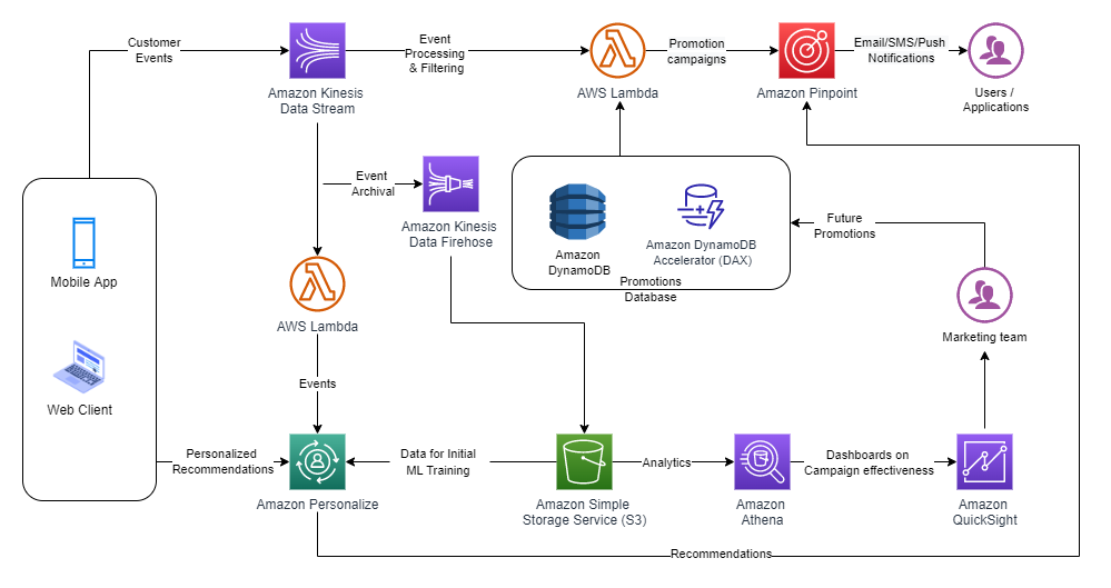
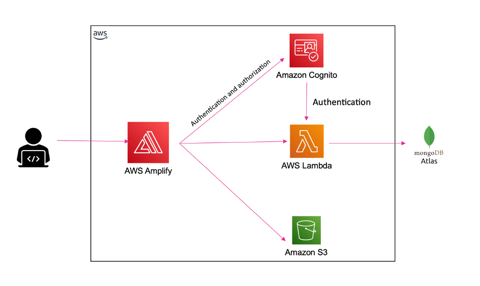
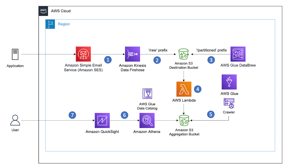
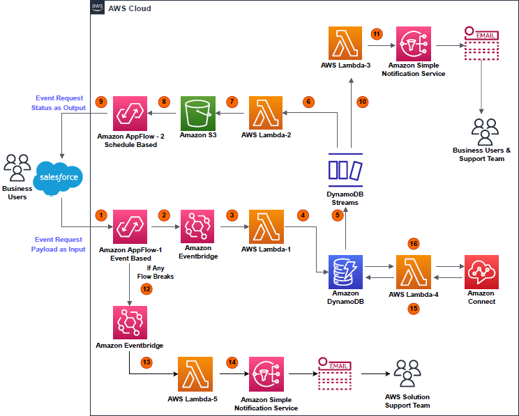
The following architecture diagram provides an overview of the solution.

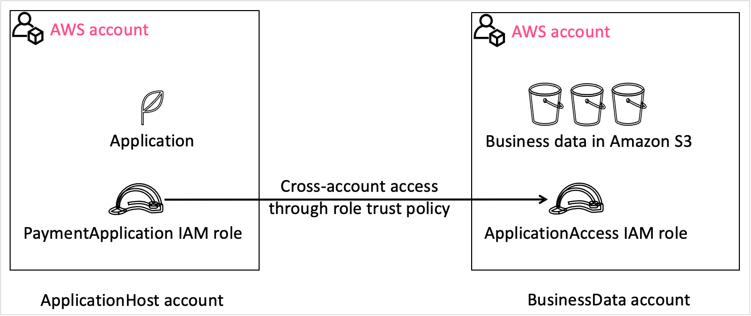
This architecture contains two separate accounts:
- Central pseudonymization service: Account 111111111111 – The pseudonymization service is running in its own dedicated AWS account (right). This is a centrally managed pseudonymization API that provides access to two resources for pseudonymization and reidentification. With this architecture, you can apply authentication, authorization, rate limiting, and other API management tasks in one place. For this solution, we’re using API keys to authenticate and authorize consumers.
- Compute: Account 222222222222 – The account on the left is referred to as the compute account, where the extract, transform, and load (ETL) workloads are running. This account depicts a consumer of the pseudonymization microservice. The account hosts the various consumer patterns depicted in the architecture diagram. These solutions are covered in detail in part 2 of this series.
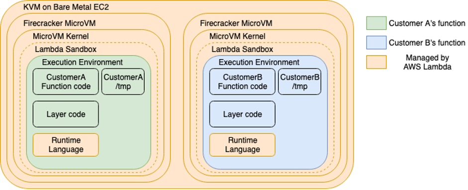
The pseudonymization service is built using AWS Lambda and Amazon API Gateway. Lambda enables the serverless microservice features, and API Gateway provides serverless APIs for HTTP or RESTful and WebSocket communication.
We create the solution resources via AWS CloudFormation. The CloudFormation stack template and the source code for the Lambda function are available in GitHub Repository.
We walk you through the following steps:
- Deploy the solution resources with AWS CloudFormation.
- Generate encryption keys and persist them in AWS Secrets Manager.
- Test the service.
Demystifying the pseudonymization service
Pseudonymization logic is written in Java and uses the AES-GCM-SIV algorithm developed by codahale. The source code is hosted in a Lambda function. Secret keys are stored securely in Secrets Manager. AWS Key Management System (AWS KMS) makes sure that secrets and sensitive components are protected at rest. The service is exposed to consumers via API Gateway as a REST API. Consumers are authenticated and authorized to consume the API via API keys. The pseudonymization service is technology agnostic and can be adopted by any form of consumer as long as they’re able to consume REST APIs.
As depicted in the following figure, the API consists of two resources with the POST method:

- Pseudonymization – The pseudonymization resource can be used by authorized users to pseudonymize a given list of plaintexts (identifiers) and replace them with a pseudonym.
- Reidentification – The reidentification resource can be used by authorized users to convert pseudonyms to plaintexts (identifiers).
The request response model of the API utilizes Java string arrays to store multiple values in a single variable, as depicted in the following code.

The API supports a Boolean type query parameter to decide whether encryption is deterministic or probabilistic.
The implementation of the algorithm has been modified to add the logic to generate a nonce, which is dependent on the plaintext being pseudonymized. If the incoming query parameters key deterministic has the value True, then the overloaded version of the encrypt function is called. This generates a nonce using the HmacSHA256 function on the plaintext, and takes 12 sub-bytes from a predetermined position for nonce. This nonce is then used for the encryption and prepended to the resulting ciphertext. The following is an example:
- Identifier –
VIN98765432101234
- Nonce –
NjcxMDVjMmQ5OTE5
- Pseudonym –
NjcxMDVjMmQ5OTE5q44vuub5QD4WH3vz1Jj26ZMcVGS+XB9kDpxp/tMinfd9
This approach is useful especially for building analytical systems that may require PII fields to be used for joining datasets with other pseudonymized datasets.
The following code shows an example of deterministic encryption.
If the incoming query parameters key deterministic has the value False, then the encrypt method is called without the deterministic parameter and the nonce generated is a random 12 bytes. This generates a different ciphertext for the same incoming plaintext.
The following code shows an example of probabilistic encryption.

The Lambda function utilizes a couple of caching mechanisms to boost the performance of the function. It uses Guava to build a cache to avoid generation of the pseudonym or identifier if it’s already available in the cache. For the probabilistic approach, the cache isn’t utilized. It also uses SecretCache, an in-memory cache for secrets requested from Secrets Manager.
Prerequisites
For this walkthrough, you should have the following prerequisites:
Deploy the solution resources with AWS CloudFormation
The deployment is triggered by running the deploy.sh script. The script runs the following phases:
- Checks for dependencies.
- Builds the Lambda package.
- Builds the CloudFormation stack.
- Deploys the CloudFormation stack.
- Prints to standard out the stack output.
The following resources are deployed from the stack:
- An API Gateway REST API with two resources:
/pseudonymization/reidentification
- A Lambda function
- A Secrets Manager secret
- A KMS key
- IAM roles and policies
- An Amazon CloudWatch Logs group
You need to pass the following parameters to the script for the deployment to be successful:
- STACK_NAME – The CloudFormation stack name.
- AWS_REGION – The Region where the solution is deployed.
- AWS_PROFILE – The named profile that applies to the AWS Command Line Interface (AWS CLI). command
- ARTEFACT_S3_BUCKET – The S3 bucket where the infrastructure code is stored. The bucket must be created in the same account and Region where the solution lives.
Use the following commands to run the ./deployments_scripts/deploy.sh script:
chmod +x ./deployment_scripts/deploy.sh ./deployment_scripts/deploy.sh -s STACK_NAME -b ARTEFACT_S3_BUCKET -r AWS_REGION -p AWS_PROFILE AWS_REGION
Upon successful deployment, the script displays the stack outputs, as depicted in the following screenshot. Take note of the output, because we use it in subsequent steps.

Generate encryption keys and persist them in Secrets Manager
In this step, we generate the encryption keys required to pseudonymize the plain text data. We generate those keys by calling the KMS key we created in the previous step. Then we persist the keys in a secret. Encryption keys are encrypted at rest and in transit, and exist in plain text only in-memory when the function calls them.
To perform this step, we use the script key_generator.py. You need to pass the following parameters for the script to run successfully:
- KmsKeyArn – The output value from the previous stack deployment
- AWS_PROFILE – The named profile that applies to the AWS CLI command
- AWS_REGION – The Region where the solution is deployed
- SecretName – The output value from the previous stack deployment
Use the following command to run ./helper_scripts/key_generator.py:
python3 ./helper_scripts/key_generator.py -k KmsKeyArn -s SecretName -p AWS_PROFILE -r AWS_REGION
Upon successful deployment, the secret value should look like the following screenshot.

Test the solution
In this step, we configure Postman and query the REST API, so you need to make sure Postman is installed in your machine. Upon successful authentication, the API returns the requested values.
The following parameters are required to create a complete request in Postman:
- PseudonymizationUrl – The output value from stack deployment
- ReidentificationUrl – The output value from stack deployment
- deterministic – The value True or False for the pseudonymization call
- API_Key – The API key, which you can retrieve from API Gateway console
Follow these steps to set up Postman:
- Start Postman in your machine.
- On the File menu, choose Import.
- Import the Postman collection.
- From the collection folder, navigate to the pseudonymization request.
- To test the pseudonymization resource, replace all variables in the sample request with the parameters mentioned earlier.
The request template in the body already has some dummy values provided. You can use the existing one or exchange with your own.
- Choose Send to run the request.
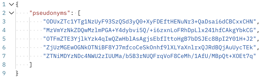
The API returns in the body of the response a JSON data type.

- From the collection folder, navigate to the reidentification request.
- To test the reidentification resource, replace all variables in the sample request with the parameters mentioned earlier.
- Pass to the response template in the body the pseudonyms output from earlier.
- Choose Send to run the request.
The API returns in the body of the response a JSON data type.

Cost and performance
There are many factors that can determine the cost and performance of the service. Performance especially can be influenced by payload size, concurrency, cache hit, and managed service limits on the account level. The cost is mainly influenced by how much the service is being used. For our cost and performance exercise, we consider the following scenario:
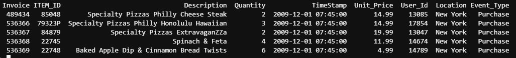
The REST API is used to pseudonymize Vehicle Identification Numbers (VINs). On average, consumers request pseudonymization of 1,000 VINs per call. The service processes on average 40 requests per second, or 40,000 encryption or decryption operations per second. The average process time per request is as follows:
- 15 milliseconds for deterministic encryption
- 23 milliseconds for probabilistic encryption
- 6 milliseconds for decryption
The number of calls hitting the service per month is distributed as follows:
- 50 million calls hitting the pseudonymization resource for deterministic encryption
- 25 million calls hitting the pseudonymization resource for probabilistic encryption
- 25 million calls hitting the reidentification resource for decryption
Based on this scenario, the average cost is $415.42 USD per month. You may find the detailed cost breakdown in the estimate generated via the AWS Pricing Calculator.
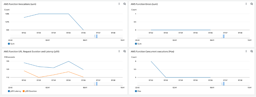
We use Locust to simulate a similar load to our scenario. Measurements from Amazon CloudWatch metrics are depicted in the following screenshots (network latency isn’t considered during our measurement).
The following screenshot shows API Gateway latency and Lambda duration for deterministic encryption. Latency is high at the beginning due to the cold start, and flattens out over time.

The following screenshot shows metrics for probabilistic encryption.

The following shows metrics for decryption.
Clean up
To avoid incurring future charges, delete the CloudFormation stack by running the destroy.sh script. The following parameters are required to run the script successfully:
- STACK_NAME – The CloudFormation stack name
- AWS_REGION – The Region where the solution is deployed
- AWS_PROFILE – The named profile that applies to the AWS CLI command
Use the following commands to run the ./deployment_scripts/destroy.sh script:
chmod +x ./deployment_scripts/destroy.sh ./deployment_scripts/destroy.sh -s STACK_NAME -r AWS_REGION -p AWS_PROFILE
Conclusion
In this post, we demonstrated how to build a pseudonymization service on AWS. The solution is technology agnostic and can be adopted by any form of consumer as long as they’re able to consume REST APIs. We hope this post helps you in your data protection strategies.
Stay tuned for part 2, which will cover consumption patterns of the pseudonymization service.
About the authors
 Edvin Hallvaxhiu is a Senior Global Security Architect with AWS Professional Services and is passionate about cybersecurity and automation. He helps customers build secure and compliant solutions in the cloud. Outside work, he likes traveling and sports.
Rahul Shaurya is a Senior Big Data Architect with AWS Professional Services. He helps and works closely with customers building data platforms and analytical applications on AWS. Outside of work, Rahul loves taking long walks with his dog Barney.
 Andrea Montanari is a Big Data Architect with AWS Professional Services. He actively supports customers and partners in building analytics solutions at scale on AWS.
María Guerra is a Big Data Architect with AWS Professional Services. Maria has a background in data analytics and mechanical engineering. She helps customers architecting and developing data related workloads in the cloud.
Pushpraj is a Data Architect with AWS Professional Services. He is passionate about Data and DevOps engineering. He helps customers build data driven applications at scale.


 Edvin Hallvaxhiu is a Senior Global Security Architect with AWS Professional Services and is passionate about cybersecurity and automation. He helps customers build secure and compliant solutions in the cloud. Outside work, he likes traveling and sports.
 Rahul Shaurya is a Senior Big Data Architect with AWS Professional Services. He helps and works closely with customers building data platforms and analytical applications on AWS. Outside of work, Rahul loves taking long walks with his dog Barney.
 Andrea Montanari is a Big Data Architect with AWS Professional Services. He actively supports customers and partners in building analytics solutions at scale on AWS.
 María Guerra is a Big Data Architect with AWS Professional Services. Maria has a background in data analytics and mechanical engineering. She helps customers architecting and developing data related workloads in the cloud.
 Pushpraj is a Data Architect with AWS Professional Services. He is passionate about Data and DevOps engineering. He helps customers build data driven applications at scale.