Tag Archives: Advanced (300)

How to unit test and deploy AWS Glue jobs using AWS CodePipeline

Post Syndicated from Praveen Kumar Jeyarajan original https://aws.amazon.com/blogs/devops/how-to-unit-test-and-deploy-aws-glue-jobs-using-aws-codepipeline/

This post is intended to assist users in understanding and replicating a method to unit test Python-based ETL Glue Jobs, using the PyTest Framework in AWS CodePipeline. In the current practice, several options exist for unit testing Python scripts for Glue jobs in a local environment. Although a local development environment may be set up to build and unit test Python-based Glue jobs, by following the documentation, replicating the same procedure in a DevOps pipeline is difficult and time consuming.

Unit test scripts are one of the initial quality gates used by developers to provide a high-quality build. One must reuse these scripts during regression testing to make sure that all of the existing functionality is intact, and that new releases don’t disrupt key application functionality. The majority of the regression test suites are expected to be integrated with the DevOps Pipeline for its execution. Unit testing an application code is a fundamental task that evaluates  whether each (unit) code written by a programmer functions as expected. Unit testing of code provides a mechanism to determine that software quality hasn’t been compromised. One of the difficulties in building Python-based Glue ETL tasks is their ability for unit testing to be incorporated within DevOps Pipeline, especially when there are modernization of mainframe ETL process to modern tech stacks in AWS

AWS Glue is a serverless data integration service that makes it easy to discover, prepare, and combine data for analytics, machine learning (ML), and application development. AWS Glue provides all of the capabilities needed for data integration. This means that you can start analyzing your data and putting it to use in minutes rather than months. AWS Glue provides both visual and code-based interfaces to make data integration easier.

Prerequisites

GitHub Repository

Amazon ECR Image URI for Glue Library

Solution overview

A typical enterprise-scale DevOps pipeline is illustrated in the following diagram. This solution describes how to incorporate the unit testing of Python-based AWS Glue ETL processes into the AWS DevOps Pipeline.

Figure 1 Solution Overview

The GitHub repository aws-glue-jobs-unit-testing has a sample Python-based Glue job in the src folder. Its associated unit test cases built using the Pytest Framework are accessible in the tests folder. An AWS CloudFormation template written in YAML is included in the deploy folder. As a runtime environment, AWS CodeBuild utilizes custom container images. This feature is used to build a project utilizing Glue libraries from Public ECR repository, that can run the code package to demonstrate unit testing integration.

Solution walkthrough

Time to read  7 min
Time to complete  15-20 min
Learning level  300
Services used
AWS CodePipeline, AWS CodeCommit, AWS CodeBuild, Amazon Elastic Container Registry (Amazon ECR) Public Repositories, AWS CloudFormation

The container image at the Public ECR repository for AWS Glue libraries includes all of the binaries required to run PySpark-based AWS Glue ETL tasks locally, as well as unit test them. The public container repository has three image tags, one for each AWS Glue version supported by AWS Glue. To demonstrate the solution, we use the image tag glue_libs_3.0.0_image_01 in this post. To utilize this container image as a runtime image in CodeBuild, copy the Image URI corresponding to the image tag that you intend to use, as shown in the following image.

Figure 2 Select Glue Library from Public ECR

The aws-glue-jobs-unit-testing GitHub repository contains a CloudFormation template, pipeline.yml, which deploys a CodePipeline with CodeBuild projects to create, test, and publish the AWS Glue job. As illustrated in the following, use the copied image URL from Amazon ECR public to create and test a CodeBuild project.

  TestBuild:
    Type: AWS::CodeBuild::Project
    Properties:
      Artifacts:
        Type: CODEPIPELINE
      BadgeEnabled: false
      Environment:
        ComputeType: BUILD_GENERAL1_LARGE
        Image: "public.ecr.aws/glue/aws-glue-libs:glue_libs_3.0.0_image_01"
        ImagePullCredentialsType: CODEBUILD
        PrivilegedMode: false
        Type: LINUX_CONTAINER
      Name: !Sub "${RepositoryName}-${BranchName}-build"
      ServiceRole: !GetAtt CodeBuildRole.Arn  

The pipeline performs the following operations:

  1. It uses the CodeCommit repository as the source and transfers the most recent code from the main branch to the CodeBuild project for further processing.
  2. The following stage is build and test, in which the most recent code from the previous phase is unit tested and the test report is published to CodeBuild report groups.
  3. If all of the test results are good, then the next CodeBuild project is launched to publish the code to an Amazon Simple Storage Service (Amazon S3) bucket.
  4. Following the successful completion of the publish phase, the final step is to deploy the AWS Glue task using the CloudFormation template in the deploy folder.

Deploying the solution

Set up

Now we’ll deploy the solution using a CloudFormation template.

  • Using the GitHub Web, download the code.zip file from the aws-glue-jobs-unit-testing repository. This zip file contains the GitHub repository’s src, tests, and deploy folders. You may also create the zip file yourself using command-line tools, such as git and zip. To create the zip file on Linux or Mac, open the terminal and enter the following commands.
git clone https://github.com/aws-samples/aws-glue-jobs-unit-testing.git
cd aws-glue-jobs-unit-testing
git checkout master
zip -r code.zip src/ tests/ deploy/
  • Sign in to the AWS Management Console and choose the AWS Region of your choice.
  • Create an Amazon S3 bucket. For more information, see How Do I Create an S3 Bucket? in the AWS documentation.
  • Upload the downloaded zip package, code.zip, to the Amazon S3 bucket that you created.

In this example, I created an Amazon S3 bucket named aws-glue-artifacts-us-east-1 in the N. Virginia (us-east-1) Region, and used the console to upload the zip package from the GitHub repository to the Amazon S3 bucket.

Figure 3 Upload code.zip file to S3 bucket

Creating the stack

  1.  In the CloudFormation console, choose Create stack.
  2. On the Specify template page, choose Upload a template file, and then choose the pipeline.yml template, downloaded from the GitHub repository

Figure 4 Upload pipeline.yml template to create a new CloudFormation stack

  1. Specify the following parameters:.
  • Stack name: glue-unit-testing-pipeline (Choose a stack name of your choice)
  • ApplicationStackName: glue-codepipeline-app (This is the name of the CloudFormation stack that will be created by the pipeline)
  • BranchName: master (This is the name of the branch to be created in the CodeCommit repository to check-in the code from the Amazon S3 bucket zip file)
  • BucketName: aws-glue-artifacts-us-east-1 (This is the name of the Amazon S3 bucket that contains the zip file. This bucket will also be used by the pipeline for storing code artifacts)
  • CodeZipFile: lambda.zip (This is the key name of the sample code Amazon S3 object. The object should be a zip file)
  • RepositoryName: aws-glue-unit-testing (This is the name of the CodeCommit repository that will be created by the stack)
  • TestReportGroupName: glue-unittest-report (This is the name of the CodeBuild test report group that will be created to store the unit test reports)

Figure 5 Fill parameters for stack creation

  1. Choose Next, and again Next.
  1. On the Review page, under Capabilities, choose the following options:
  • I acknowledge that CloudFormation might create IAM resources with custom names.

Figure 6 Acknowledge IAM roles creation

  1. Choose Create stack to begin the stack creation process. Once the stack creation is complete, the resources that were created are displayed on the Resources tab. The stack creation takes approximately 5-7 minutes.

Figure 7 Successful completion of stack creation

The stack automatically creates a CodeCommit repository with the initial code checked-in from the zip file uploaded to the Amazon S3 bucket. Furthermore, it creates a CodePipeline view using the CodeCommit repository as the source. In the above example, the CodeCommit repository is aws-glue-unit-test, and the pipeline is aws-glue-unit-test-pipeline.

Testing the solution

To test the deployed pipeline, open the CodePipeline console and select the pipeline created by the CloudFormation stack. Select the Release Change button on the pipeline page.

Figure 8 Choose Release Change on pipeline page

The pipeline begins its execution with the most recent code in the CodeCommit repository.

When the Test_and_Build phase is finished, select the Details link to examine the execution logs.

Figure 9 Successfully completed the Test_and_Build stage

Select the Reports tab, and choose the test report from Report history to view the unit execution results.

Figure 10 Test report from pipeline execution

Finally, after the deployment stage is complete, you can see, run, and monitor the deployed AWS Glue job on the AWS Glue console page. For more information, refer to the Running and monitoring AWS Glue documentation

Figure 11 Successful pipeline execution

Cleanup

To avoid additional infrastructure costs, make sure that you delete the stack after experimenting with the examples provided in the post. On the CloudFormation console, select the stack that you created, and then choose Delete. This will delete all of the resources that it created, including CodeCommit repositories, IAM roles/policies, and CodeBuild projects.

Summary

In this post, we demonstrated how to unit test and deploy Python-based AWS Glue jobs in a pipeline with unit tests written with the PyTest framework. The approach is not limited to CodePipeline, and it can be used to build up a local development environment, as demonstrated in the Big Data blog. The aws-glue-jobs-unit-testing GitHub repository contains the example’s CloudFormation template, as well as sample AWS Glue Python code and Pytest code used in this post. If you have any questions or comments regarding this example, please open an issue or submit a pull request.

Authors:
Praveen Kumar Jeyarajan

Praveen Kumar Jeyarajan is a PraveenKumar is a Senior DevOps Consultant in AWS supporting Enterprise customers and their journey to the cloud. He has 11+ years of DevOps experience and is skilled in solving myriad technical challenges using the latest technologies. He holds a Masters degree in Software Engineering. Outside of work, he enjoys watching movies and playing tennis.

Vaidyanathan Ganesa Sankaran

Vaidyanathan Ganesa Sankaran is a Sr Modernization Architect at AWS supporting Global Enterprise customers on their journey towards modernization. He is specialized in Artificial intelligence, legacy Modernization and Cloud Computing. He holds a Masters degree in Software Engineering and has 12+ years of Modernization experience. Outside work, he loves conducting training sessions for college grads and professional starter who wants to learn cloud and AI. His hobbies are playing tennis, philately and traveling.

Smithy Server and Client Generator for TypeScript (Developer Preview)

Post Syndicated from Adam Thomas original https://aws.amazon.com/blogs/devops/smithy-server-and-client-generator-for-typescript/

We’re excited to announce the Developer Preview of Smithy’s server and client generators for TypeScript. This enables developers to write concise, type-safe code in the same model-first manner that AWS has used to develop its services. Smithy is AWS’s open-source Interface Definition Language (IDL) for web services. AWS uses Smithy and its internal predecessor to model services, generate server scaffolding, and generate rich clients in multiple languages, such as the AWS SDKs.

If you’re unfamiliar with Smithy, check out the Smithy website and watch an introductory talk from Michael Dowling, Smithy’s Principal Engineer.

This post will demonstrate how you can write a simple Smithy model, write a service that implements the model, deploy it to AWS Lambda, and call it using a generated client.

What can the server generator do for me?

Using Smithy and its server generator unlocks model-first development. Model-first development puts your customers first. This forces you to define your interface first rather than let your API to become implicitly defined by your implementation choices.

Smithy’s server generator for TypeScript enables development at a higher level of abstraction. By making serialization, deserialization, and routing an implementation detail in generated code, service developers can focus on writing code against modeled types, rather than against raw HTTP requests. Your business logic and unit tests will be cleaner and more readable, and the way that your messages are represented on the wire is defined explicitly by a protocol, not implicitly by your JSON parser.

The server generator also lets you leverage TypeScript’s type safety. Not only is the business logic of your service written against strongly typed interfaces, but also you can reference your service’s types in your AWS Cloud Development Kit (AWS CDK) definition. This makes sure that your stack will fail at build time rather than deployment time if it’s out of sync with your model.

Finally, using Smithy for service generation lets you ship clients in Smithy’s growing portfolio of generated clients. We’re unveiling a developer preview of the client generator for TypeScript today as well, and we’ll continue to unveil more implementations in the future.

The architecture of a Smithy service

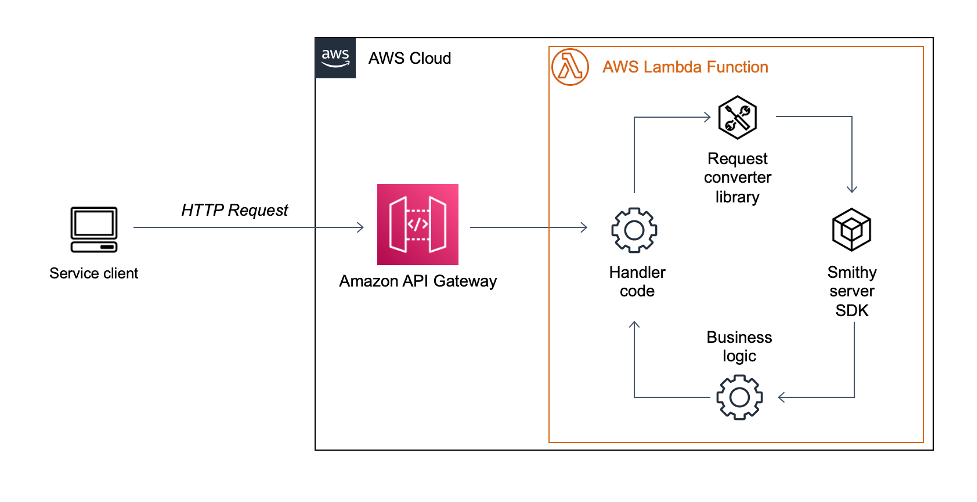
A Smithy service looks much like any other web service running on Lambda behind Amazon API Gateway. The difference lies in the code itself. Where a standard service might use a generic deserializer to parse an incoming request and bind it to an object, a Smithy service relies on code generation for deserialization, serialization, validation, and the object model itself. These functions are generated into a standalone library known as a Smithy server SDK. Using a server SDK with one of AWS’s prepackaged request converters, service developers can focus on their business logic, rather than the undifferentiated heavy lifting of parsing and generating HTTP requests and responses.

A data flow diagram for a Smithy service

Walkthrough

This post will walk you through the process of building and using a Smithy service, from modeling to deployment.

By the end, you should be able to:

  • Model a simple REST service in Smithy
  • Generate a Smithy server SDK for TypeScript
  • Implement a service in Lambda using the generated server SDK
  • Deploy the service to AWS using the AWS CDK
  • Generate a client SDK, and use it to call the deployed service

The complete example described in this post can be found here.

Prerequisites

For this walkthrough, you should have the following prerequisites:

Checking out the sample repository

Create a new repository from the template repository here.

To clone the application in your browser

  1. Open https://github.com/aws-samples/smithy-server-generator-typescript-sample in your browser
  2. Select “Use this template” in the top right-hand corner
  3. Fill out the form, and select “Create repository from template”
  4. Clone your new repository from GitHub by following the instructions in the “Code” dropdown

Exploring and setting up the sample application

The sample application is split into three separate submodules:

  • model – contains the Smithy model that defines the service
  • Server – contains the code generation setup, application logic, and CDK stack for the service
  • typescript-client – contains the code generation setup for a rich client generated in TypeScript

To bootstrap the sample application and run the initial build

  1. Open a terminal and navigate to the root of the sample application
  2. Run the following command:
    ./gradlew build && yarn install
  3. Wait until the build finishes successfully

Modeling a service using Smithy

In an IDE of your choice, open the file at model/src/main/smithy/main.smithy. This file defines the interface for the sample web service, a service that can echo strings back to the caller, as well as provide the string length.

The service definition forms the root of a Smithy model. It defines the operations that are available to clients, as well as common errors that are thrown by all of the operations in a service.


@sigv4(name: "execute-api")
@restJson1
service StringWizard {
    version: "2018-05-10",
    operations: [Echo, Length],
    errors: [ValidationException],
}

This service uses the @sigv4 trait to indicate that calls must be signed with AWS Signature V4. In the sample application, API Gateway’s Identity and Access Management (IAM) Authentication support provides this functionality.

@restJson1 indicates the protocol supported by this service. RestJson1 is Smithy’s built-in protocol for RESTful web services that use JSON for requests and responses.

This service advertises two operations: Echo and Length. Furthermore, it indicates that every operation on the service must be expected to throw ValidationException, if an invalid input is supplied.

Next, let’s look at the definition of the Length operation and its input type.

/// An operation that computes the length of a string
/// provided on the URI path
@readonly
@http(code: 200, method: "GET", uri: "/length/{string}",)
operation Length {
     input: LengthInput,
     output: LengthOutput,
     errors: [PalindromeException],
}

@input
structure LengthInput {
     @required
     @httpLabel
     string: String,
}

This operation uses the @http trait to model how requests are processed with restJson1, including the method (GET) and how the URI is formed (using a label to bind the string field from LengthInput to a path segment). HTTP binding with Smithy can be explored in depth at Smithy’s documentation page.

Note that this operation can also throw a PalindromeException, which we’ll explore in more detail when we check out the business logic.

Updating the Smithy model to add additional constraints to the input

Smithy constraint traits are used to enable additional validation for input types. Server SDKs automatically perform validation based on the Smithy constraints in the model. Let’s add a new constraint to the input for the Length operation. Moreover, let’s make sure that only alphanumeric characters can be passed in by the caller.

  1. Open model/src/main/smithy/main.smithy in an editor
  2. Add a @pattern constraint to the string member of Length input. It should look like this:
    structure LengthInput {
        @required
        @httpLabel
        @pattern(“^[a-zA-Z0-9]$”)
        string: String,
    }
  3. Open a terminal, and navigate to the root of the sample application
  4. Run the following command:
    yarn build
  5. Wait for the build to finish successfully

Using the Smithy Server Generator for TypeScript

The key component of a Smithy web service is its code generator, which translates the Smithy model into actual code. You’ve already run the code generator – it runs every time that you build the sample application.

The codegen directory inside of the server submodule is where the Smithy Server Generator for TypeScript is configured and run. The server generator uses Smithy Build to build, and it’s configured by smithy-build.json.

{
  "version" : "1.0",
  "outputDirectory" : "build/output",
  "projections" : {
      "ts-server" : {
         "plugins": {
           "typescript-ssdk-codegen" : {
              "package" : "@smithy-demo/string-wizard-service-ssdk",
              "packageVersion": "0.0.1"
           }
        }
      },
      "apigateway" : {
        "plugins" : {
          "openapi": {
             "service": "software.amazon.smithy.demo#StringWizard",
             "protocol": "aws.protocols#restJson1",
             "apiGatewayType" : "REST"
           }
         }
      }
   }
}

This smithy-build configures two projections. The ts-server projection generates the server SDK by invoking the typescript-ssdk-codegen plugin. The package and packageVersion arguments are used to generate an npm package that you can add as a dependency in your server code.

The OpenAPI projection configures Smithy’s OpenAPI converter to generate a file that can be imported into API Gateway to host this service. It uses Smithy’s ability to extend models via the imports keyword to extend the base model with an additional API Gateway configuration. The generated OpenAPI specification is used by the CDK stack, which we’ll explore later.

If you open package.json in the server submodule, then you’ll notice this line in the dependencies section:

"@smithy-demo/string-wizard-service-ssdk": "workspace:server/codegen/build/smithyprojections/server-codegen/ts-server/typescript-ssdk-codegen"

The key, @smithy-demo/string-wizard-service-ssdk, matches the package key in the smithy-build.json file. The value uses Yarn’s workspaces feature to set up a local dependency on the generated server SDK. This lets you use the server SDK as a standalone npm dependency without publishing it to a repository. Since we bundle the server application into a zip file before uploading it to Lambda, you can treat the server SDK as an implementation detail that isn’t published externally.

We won’t get into the details here, but you can see the specifics of how the code generator is invoked by looking at the regenerate:ssdk script in the server’s package.json, as well as the build.gradle file in the server’s codegen directory.

Implementing an operation using a server SDK

The server generator takes care of the undifferentiated heavy lifting of writing a Smithy service. However, there are still two tasks left for the service developer: writing the Lambda entrypoint, and implementing the operation’s business logic.

First, let’s look at the entrypoint for the Length operation. Open server/src/length_handler.ts in an editor. You should see the following content:

import { getLengthHandler } from "@smithy-demo/string-wizard-service-ssdk";
import { APIGatewayProxyHandler } from "aws-lambda";
import { LengthOperation } from "./length";
import { getApiGatewayHandler } from "./apigateway";
// This is the entry point for the Lambda Function that services the LengthOperation
export const lambdaHandler: APIGatewayProxyHandler = getApiGatewayHandler(getLengthHandler(LengthOperation));

If you’ve written a Lambda entry-point before, then exporting a function of type APIGatewayProxyHandler will be familiar to you. However, there are a few new pieces here. First, we have a function from the server SDK, called getLengthHandler, that takes a Smithy Operation type and returns a ServiceHandler. Operation is the interface that the server SDK uses to encapsulate business logic. The core task of implementing a Smithy service is to implement Operations. ServiceHandler is the interface that encapsulates the generated logic of a server SDK. It’s the black box that handles serialization, deserialization, error handling, validation, and routing.

The getApiGatewayHandler function simply invokes the request and response conversion logic, and then builds a custom context for the operation. We won’t go into their details here.

Next, let’s explore the operation implementation. Open server/src/length.ts in an editor. You should see the following content:

import { Operation } from "@aws-smithy/server-common";
import {
  LengthServerInput,
  LengthServerOutput,
  PalindromeException,
} from "@smithy-demo/string-wizard-service-ssdk";
import { HandlerContext } from "./apigateway";
import { reverse } from "./util";

// This is the implementation of business logic of the LengthOperation
export const LengthOperation: Operation<LengthServerInput, LengthServerOutput, HandlerContext> = async (
  input,
  context
) => {
  console.log(`Received Length operation from: ${context.user}`);

  if (input.string != undefined && input.string === reverse(input.string)) {
     throw new PalindromeException({ message: "Cannot handle palindrome" });
  }

  return {
     length: input.string?.length,
  };
};

Let’s look at this implementation piece-by-piece. First, the function type Operation<LengthServerInput, LengthServerOutput, HandlerContext> provides the type-safe interface for our business logic. LengthServerInput and LengthServerOutput are the code generated types that correspond to the input and output types for the Length operation in our Smithy model. If we use the wrong type arguments for the Operation, then it will fail type checks against the getLengthHandler function in the entry-point. If we try to access the incorrect properties on the input, then we’ll also see type checker failures. This is one of the core tenets of the Smithy Server Generator for TypeScript: writing a web service should be as strongly typed as writing anything else.

Next, let’s look at the section that validates that the input isn’t a palindrome:

if (input.string != undefined && input.string === reverse(input.string)) {
    throw new PalindromeException({ message: "Cannot handle palindrome" });
}

Although the server SDK can validate the input against Smithy’s constraint traits, there is no constraint trait for rejecting palindromes. Therefore, we must include this validation in our business logic. Our Smithy model includes a PalindromeException definition that includes a message member. This is generated as a standard subclass of Error with a constructor that takes in a message that your operation implementation can throw like any other error. This will be caught and properly rendered as a response by the server SDK.

Finally, there’s the return statement. Since the Smithy model defines LengthOutput as a structure containing an integer member called length, we return an object that has the same structural type here.

Note that this business logic doesn’t have to consider serialization, or the wire format of the request or response, let alone anything else related to HTTP or API Gateway. The unit tests in src/length/length.spec.ts reflect this. They’re the same standard unit tests as you would write against any other TypeScript class. The server SDK lets you write your business logic at a higher level of abstraction, thus simplifying your unit testing and letting your developers focus on their business logic rather than the messy details.

Deploying the sample application

The sample application utilizes the AWS CDK to deploy itself to your AWS account. Explore the CDK definition in server/lib/cdk-stack.ts. An in-depth exploration of the stack is out of the scope for this post, but it looks largely like any other AWS application that deploys TypeScript code to Lambda behind API Gateway.

The key difference is that the cdk stack can rely on a generated OpenAPI definition for the API Gateway resource. This makes sure that your deployed application always matches your Smithy model. Furthermore, it can use the server SDK’s generated types to make sure that every modeled operation has an implementation deployed to Lambda. This means that forgetting to wire up the implementation for a new operation becomes a compile-time failure, rather than a runtime one.

To deploy the sample application from the command line

    1. Open a terminal and navigate to the server directory of your sample application.
    2. Run the following command:
      yarn cdk deploy
    3. The cdk will display a list of security-sensitive resources that will be deployed to your account. These consist mostly of AWS Identity and Access Management (IAM) roles used by your Lambda functions for execution. Enter y to continue deploying the application to your account.
    4. When it has completed, the CDK will print your new application’s endpoint and the CloudFormation stack containing your application to the console. It will look something like the following:
      Outputs:
          StringWizardService.StringWizardApiEndpoint59072E9B
          = https://RANDOMSTRING.execute-api.us-west-2.amazonaws.com/prod/
      	
      Stack ARN:
          arn:aws:cloudformation:us-west-2:YOURACCOUNTID:stack/StringWizardService/SOME-UUID
    5. Log on to your AWS account in the AWS Management Console.
    6. Navigate to the Lambda console. You should see two new functions: one that starts with StringWizardService-EchoFunction, and one that starts with StringWizardService-EchoFunction. These are the implementations of your Smithy service’s operations.
    7. Navigate to the Amazon API Gateway console. You should see a new REST API named StringWizardAPI, with Resources POST /echo and GET /length/{string}, corresponding to your Smithy model.

    Calling the sample application with a generated client

    The last piece of the Smithy puzzle is the strongly-typed generated client generated by the Smithy Client Generator for TypeScript. It’s located in the typescript-client folder, which has a codegen folder that uses SmithyBuild to generate a client in much the same manner as the server.

    The sample application ships with a simple wrapper script for the length operation that uses the generated client to build a rudimentary CLI. Open the typescript-client/bin/length.ts file in your editor. The contents will look like the following:

    #!/usr/bin/env node
    
    import {LengthCommand, StringWizardClient} from "@smithy-demo/string-client";
    
    const client = new StringWizardClient({endpoint: process.argv[2]});
    
    client.send(new LengthCommand({
         string: process.argv[3]
    })).catch((err) => {
         console.log("Failed with error: " + err);
    process.exit(1);
    }).then((res) => {
         process.stderr.write(res.length?.toString() ?? "0");
    });

    If you’ve used the AWS SDK for JavaScript v3, this will look familiar. This is because it’s generated using the Smithy Client Generator for TypeScript!

    From the code, you can see that the CLI takes two positional arguments: the endpoint for the deployed application, and an input string. Let’s give it a spin.

    To call the deployed application using the generated client

    1. Open a terminal and navigate to the typescript-client directory.
    2. Run the following command to build the client:
      yarn build
    3. Using the endpoint output by the CDK in the Deploying the sample application section above, run the following command:
      yarn run str-length https://RANDOMSTRING.execute-api.us-west-2.amazonaws.com/prod/ foo 
    4. You should see an output of 3, the length of foo.
    5. Next, trigger anerror by calling your endpoint with a palindrome by running the following command:
      yarn run str-length https://RANDOMSTRING.execute-api.us-west-2.amazonaws.com/prod/ kayak
    6. You should see the following output:
      Failed with error: PalindromeException: Cannot handle palindrome

    Cleaning up

    To avoid incurring future charges, delete the resources.

    To delete the sample application using the CDK

    1. Open a terminal and navigate to the server directory.
    2. Run the following command:
      yarn cdk destroy StringWizardService
    3. Answer y to the prompt Are you sure you want to delete: StringWizardService (y/n)?
    4. Wait for the CDK to complete the deletion of your CloudFormation stack. You should see the following when it has completed:
      ✅ StringWizardService: destroyed

    Conclusion

    You have now used a Smithy model to define a service, explored how a generated server SDK can simplify your web service development, deployed the service to the AWS Cloud using the AWS CDK, and called the service using a strongly-typed generated client.

    If you aren’t familiar with Smithy, but you want to learn more, then don’t forget to check out the documentation or the introductory video.

    To learn more about the Smithy Server Generator for TypeScript, check out its documentation.

    If you have feature requests, bug reports, feedback of any kind, or would like to contribute, head over to the GitHub repository.

    Adam Thomas

    Adam Thomas is a Senior Software Development engineer on the Smithy team. He has been a web service developer at Amazon for over ten years. Outside of work, Adam is a passionate advocate for staying inside, playing video games, and reading fiction.

How to control access to AWS resources based on AWS account, OU, or organization

Post Syndicated from Rishi Mehrotra original https://aws.amazon.com/blogs/security/how-to-control-access-to-aws-resources-based-on-aws-account-ou-or-organization/

AWS Identity and Access Management (IAM) recently launched new condition keys to make it simpler to control access to your resources along your Amazon Web Services (AWS) organizational boundaries. AWS recommends that you set up multiple accounts as your workloads grow, and you can use multiple AWS accounts to isolate workloads or applications that have specific security requirements. By using the new conditions, aws:ResourceOrgID, aws:ResourceOrgPaths, and aws:ResourceAccount, you can define access controls based on an AWS resource’s organization, organizational unit (OU), or account. These conditions make it simpler to require that your principals (users and roles) can only access resources inside a specific boundary within your organization. You can combine the new conditions with other IAM capabilities to restrict access to and from AWS accounts that are not part of your organization.

This post will help you get started using the new condition keys. We’ll show the details of the new condition keys and walk through a detailed example based on the following scenario. We’ll also provide references and links to help you learn more about how to establish access control perimeters around your AWS accounts.

Consider a common scenario where you would like to prevent principals in your AWS organization from adding objects to Amazon Simple Storage Service (Amazon S3) buckets that don’t belong to your organization. To accomplish this, you can configure an IAM policy to deny access to S3 actions unless aws:ResourceOrgID matches your unique AWS organization ID. Because the policy references your entire organization, rather than individual S3 resources, you have a convenient way to maintain this security posture across any number of resources you control. The new conditions give you the tools to create a security baseline for your IAM principals and help you prevent unintended access to resources in accounts that you don’t control. You can attach this policy to an IAM principal to apply this rule to a single user or role, or use service control policies (SCPs) in AWS Organizations to apply the rule broadly across your AWS accounts. IAM principals that are subject to this policy will only be able to perform S3 actions on buckets and objects within your organization, regardless of their other permissions granted through IAM policies or S3 bucket policies.

New condition key details

You can use the aws:ResourceOrgID, aws:ResourceOrgPaths, and aws:ResourceAccount condition keys in IAM policies to place controls on the resources that your principals can access. The following table explains the new condition keys and what values these keys can take.

Condition key Description Operator Single/multi value Value
aws:ResourceOrgID AWS organization ID of the resource being accessed All string operators Single value key Any AWS organization ID
aws:ResourceOrgPaths Organization path of the resource being accessed All string operators Multi-value key Organization paths of AWS organization IDs and organizational unit IDs
aws:ResourceAccount AWS account ID of the resource being accessed All string operators Single value key Any AWS account ID

Note: Of the three keys, only aws:ResourceOrgPaths is a multi-value condition key, while aws:ResourceAccount and aws:ResourceOrgID are single-value keys. For information on how to use multi-value keys, see Creating a condition with multiple keys or values in the IAM documentation.

Resource owner keys compared to principal owner keys

The new IAM condition keys complement the existing principal condition keys aws:PrincipalAccount, aws:PrincipalOrgPaths, and aws:PrincipalOrgID. The principal condition keys help you define which AWS accounts, organizational units (OUs), and organizations are allowed to access your resources. For more information on the principal conditions, see Use IAM to share your AWS resources with groups of AWS accounts in AWS Organizations on the AWS Security Blog.

Using the principal and resource keys together helps you establish permission guardrails around your AWS principals and resources, and makes it simpler to keep your data inside the organization boundaries you define as you continue to scale. For example, you can define identity-based policies that prevent your IAM principals from accessing resources outside your organization (by using the aws:ResourceOrgID condition). Next, you can define resource-based policies that prevent IAM principals outside your organization from accessing resources that are inside your organization boundary (by using the aws:PrincipalOrgID condition). The combination of both policies prevents any access to and from AWS accounts that are not part of your organization. In the next sections, we’ll walk through an example of how to configure the identity-based policy in your organization. For the resource-based policy, you can follow along with the example in An easier way to control access to AWS resources by using the AWS organization of IAM principals on the AWS Security blog.

Setup for the examples

In the following sections, we’ll show an example IAM policy for each of the new conditions. To follow along with Example 1, which uses aws:ResourceAccount, you’ll just need an AWS account.

To follow along with Examples 2 and 3 that use aws:ResourceOrgPaths and aws:ResourceOrgID respectively, you’ll need to have an organization in AWS Organizations and at least one OU created. This blog post assumes that you have some familiarity with the basic concepts in IAM and AWS Organizations. If you need help creating an organization or want to learn more about AWS Organizations, visit Getting Started with AWS Organizations in the AWS documentation.

Which IAM policy type should I use?

You can implement the following examples as identity-based policies, or in SCPs that are managed in AWS Organizations. If you want to establish a boundary for some of your IAM principals, we recommend that you use identity-based policies. If you want to establish a boundary for an entire AWS account or for your organization, we recommend that you use SCPs. Because SCPs apply to an entire AWS account, you should take care when you apply the following policies to your organization, and account for any exceptions to these rules that might be necessary for some AWS services to function properly.

Example 1: Restrict access to AWS resources within a specific AWS account

Let’s look at an example IAM policy that restricts access along the boundary of a single AWS account. For this example, say that you have an IAM principal in account 222222222222, and you want to prevent the principal from accessing S3 objects outside of this account. To create this effect, you could attach the following IAM policy.

{
  "Version": "2012-10-17",
  "Statement": [
    {
      "Sid": " DenyS3AccessOutsideMyBoundary",
      "Effect": "Deny",
      "Action": [
        "s3:*"
      ],
      "Resource": "*",
      "Condition": {
        "StringNotEquals": {
          "aws:ResourceAccount": [
            "222222222222"
          ]
        }
      }
    }
  ]
}

Note: This policy is not meant to replace your existing IAM access controls, because it does not grant any access. Instead, this policy can act as an additional guardrail for your other IAM permissions. You can use a policy like this to prevent your principals from access to any AWS accounts that you don’t know or control, regardless of the permissions granted through other IAM policies.

This policy uses a Deny effect to block access to S3 actions unless the S3 resource being accessed is in account 222222222222. This policy prevents S3 access to accounts outside of the boundary of a single AWS account. You can use a policy like this one to limit your IAM principals to access only the resources that are inside your trusted AWS accounts. To implement a policy like this example yourself, replace account ID 222222222222 in the policy with your own AWS account ID. For a policy you can apply to multiple accounts while still maintaining this restriction, you could alternatively replace the account ID with the aws:PrincipalAccount condition key, to require that the principal and resource must be in the same account (see example #3 in this post for more details how to accomplish this).

Organization setup: Welcome to AnyCompany

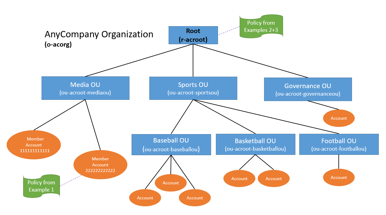
For the next two examples, we’ll use an example organization called AnyCompany that we created in AWS Organizations. You can create a similar organization to follow along directly with these examples, or adapt the sample policies to fit your own organization. Figure 1 shows the organization structure for AnyCompany.

Figure 1: Organization structure for AnyCompany

Figure 1: Organization structure for AnyCompany

Like all organizations, AnyCompany has an organization root. Under the root are three OUs: Media, Sports, and Governance. Under the Sports OU, there are three more OUs: Baseball, Basketball, and Football. AWS accounts in this organization are spread across all the OUs based on their business purpose. In total, there are six OUs in this organization.

Example 2: Restrict access to AWS resources within my organizational unit

Now that you’ve seen what the AnyCompany organization looks like, let’s walk through another example IAM policy that you can use to restrict access to a specific part of your organization. For this example, let’s say you want to restrict S3 object access within the following OUs in the AnyCompany organization:

  • Media
  • Sports
  • Baseball
  • Basketball
  • Football

To define a boundary around these OUs, you don’t need to list all of them in your IAM policy. Instead, you can use the organization structure to your advantage. The Baseball, Basketball, and Football OUs share a parent, the Sports OU. You can use the new aws:ResourceOrgPaths key to prevent access outside of the Media OU, the Sports OU, and any OUs under it. Here’s the IAM policy that achieves this effect.

{
  "Version": "2012-10-17",
  "Statement": [
    {
      "Sid": " DenyS3AccessOutsideMyBoundary",
      "Effect": "Deny",
      "Action": [
        "s3:*"
      ],
      "Resource": "*",
      "Condition": {
        "ForAllValues:StringNotLike": {
          "aws:ResourceOrgPaths": [
            "o-acorg/r-acroot/ou-acroot-mediaou/",
            "o-acorg/r-acroot/ou-acroot-sportsou/*"
          ] 
        }
      }
    }
  ]
}

Note: Like the earlier example, this policy does not grant any access. Instead, this policy provides a backstop for your other IAM permissions, preventing your principals from accessing S3 objects outside an OU-defined boundary. If you want to require that your IAM principals consistently follow this rule, we recommend that you apply this policy as an SCP. In this example, we attached this policy to the root of our organization, applying it to all principals across all accounts in the AnyCompany organization.

The policy denies access to S3 actions unless the S3 resource being accessed is in a specific set of OUs in the AnyCompany organization. This policy is identical to Example 1, except for the condition block: The condition requires that aws:ResourceOrgPaths contains any of the listed OU paths. Because aws:ResourceOrgPaths is a multi-value condition, the policy uses the ForAllValues:StringNotLike operator to compare the values of aws:ResourceOrgPaths to the list of OUs in the policy.

The first OU path in the list is for the Media OU. The second OU path is the Sports OU, but it also adds the wildcard character * to the end of the path. The wildcard * matches any combination of characters, and so this condition matches both the Sports OU and any other OU further down its path. Using wildcards in the OU path allows you to implicitly reference other OUs inside the Sports OU, without having to list them explicitly in the policy. For more information about wildcards, refer to Using wildcards in resource ARNs in the IAM documentation.

Example 3: Restrict access to AWS resources within my organization

Finally, we’ll look at a very simple example of a boundary that is defined at the level of an entire organization. This is the same use case as the preceding two examples (restrict access to S3 object access), but scoped to an organization instead of an account or collection of OUs.

{
  "Version": "2012-10-17",
  "Statement": [
    {
      "Sid": "DenyS3AccessOutsideMyBoundary",
      "Effect": "Deny",
      "Action": [
        "s3:*"
      ],
      "Resource": "arn:aws:s3:::*/*",
      "Condition": {
        "StringNotEquals": {
          "aws:ResourceOrgID": "${aws:PrincipalOrgID}"
        }
      }
    }
  ]
}

Note: Like the earlier examples, this policy does not grant any access. Instead, this policy provides a backstop for your other IAM permissions, preventing your principals from accessing S3 objects outside your organization regardless of their other access permissions. If you want to require that your IAM principals consistently follow this rule, we recommend that you apply this policy as an SCP. As in the previous example, we attached this policy to the root of our organization, applying it to all accounts in the AnyCompany organization.

The policy denies access to S3 actions unless the S3 resource being accessed is in the same organization as the IAM principal that is accessing it. This policy is identical to Example 1, except for the condition block: The condition requires that aws:ResourceOrgID and aws:PrincipalOrgID must be equal to each other. With this requirement, the principal making the request and the resource being accessed must be in the same organization. This policy also applies to S3 resources that are created after the policy is put into effect, so it is simple to maintain the same security posture across all your resources.

For more information about aws:PrincipalOrgID, refer to AWS global condition context keys in the IAM documentation.

Learn more

In this post, we explored the new conditions, and walked through a few examples to show you how to restrict access to S3 objects across the boundary of an account, OU, or organization. These tools work for more than just S3, though: You can use the new conditions to help you protect a wide variety of AWS services and actions. Here are a few links that you may want to look at:

If you have any questions, comments, or concerns, contact AWS Support or start a new thread on the AWS Identity and Access Management forum. Thanks for reading about this new feature. If you have feedback about this post, submit comments in the Comments section below.

Want more AWS Security news? Follow us on Twitter.

Rishi Mehrotra

Rishi Mehrotra

Rishi is a Product Manager in AWS IAM. He enjoys working with customers and influencing products decisions. Prior to Amazon, Rishi worked for enterprise IT customers after receiving engineering degree in computer science. He recently pursued MBA from The University of Chicago Booth School of Business. Outside of work, Rishi enjoys biking, reading, and playing with his kids.

Author

Michael Switzer

Mike is the product manager for the Identity and Access Management service at AWS. He enjoys working directly with customers to identify solutions to their challenges, and using data-driven decision making to drive his work. Outside of work, Mike is an avid cyclist and outdoorsperson. He holds a master’s degree in computational mathematics from the University of Washington.

Extend your pre-commit hooks with AWS CloudFormation Guard

Post Syndicated from Joaquin Manuel Rinaudo original https://aws.amazon.com/blogs/security/extend-your-pre-commit-hooks-with-aws-cloudformation-guard/

Git hooks are scripts that extend Git functionality when certain events and actions occur during code development. Developer teams often use Git hooks to perform quality checks before they commit their code changes. For example, see the blog post Use Git pre-commit hooks to avoid AWS CloudFormation errors for a description of how the AWS Integration and Automation team uses various pre-commit hooks to help reduce effort and errors when they build AWS Quick Starts.

This blog post shows you how to extend your Git hooks to validate your AWS CloudFormation templates against policy-as-code rules by using AWS CloudFormation Guard. This can help you verify that your code follows organizational best practices for security, compliance, and more by preventing you from commit changes that fail validation rules.

We will also provide patterns you can use to centrally maintain a list of rules that security teams can use to roll out new security best practices across an organization. You will learn how to configure a pre-commit framework by using an example repository while you store Guard rules in both a central Amazon Simple Storage Service (Amazon S3) bucket or in versioned code repositories (such as AWS CodeCommit, GitHub, Bitbucket, or GitLab).

Prerequisites

To complete the steps in this blog post, first perform the following installations.

  1. Install AWS Command Line Interface (AWS CLI).
  2. Install the Git CLI.
  3. Install the pre-commit framework by running the following command.
    pip install pre-commit
  4. Install the Rust programming language by following these instructions.
  5. (Windows only) Install the version of Microsoft Visual C++ Build Tools 2019 that provides just the Visual C++ build tools. 

Solution walkthrough

In this section, we walk you through an exercise to extend a Java service on an Amazon EKS example repository with Git hooks by using AWS CloudFormation Guard. You can choose to upload your Guard rules in either a separate GitHub repository or your own S3 bucket.

First, download the sample repository that you will add the pre-commit framework to.

To clone the test repository

  • Clone the repo to a local directory by running the following command in your local terminal.

    git clone https://github.com/aws-samples/amazon-eks-example-for-stateful-java-service.git

Next, create Guard rules that reflect the organization’s policy-as-code best practices and store them in an S3 bucket.

To set up an S3 bucket with your Guard rules

  1. Create an S3 bucket by running the following command in the AWS CLI.

    aws s3 mb s3://<account-id>-cfn-guard-rules --region <aws-region>

    where <account-id> is the ID of the AWS account you’re using and <aws-region> is the AWS Region you want to use.

  2. (Optional) Alternatively, you can follow the Getting started with Amazon S3 tutorial to create the bucket and upload the object (as described in step 4 that follows) by using the AWS Management Console.

    When you store your Guard rules in an S3 bucket, you can make the rules accessible to other member accounts in your organization by using the aws:PrincipalOrgID condition and setting the value to your organization ID in the bucket policy.

  3. Create a file that contains a Guard rule named rules.guard, with the following content.
    let eks_cluster = Resources.* [ Type == 'AWS::EKS::Cluster' ]
    rule eks_public_disallowed when %eks_cluster !empty {
          %eks_cluster.Properties.ResourcesVpcConfig.EndpointPublicAccess == false
    }

    This rule will verify that public endpoints are disabled by checking that resources that are created by using the AWS::EKS::Cluster resource type have the EndpointPublicAccess property set to false. For more information about authoring your own rules using Guard domain-specific language (DSL), see Introducing AWS CloudFormation Guard 2.0.

  4. Upload the rule set to your S3 bucket by running the following command in the AWS CLI.

    aws s3 cp rules.guard s3://<account-id>-cfn-guard-rules/rules/rules.guard

In the next step, you will set up the pre-commit framework in the repository to run CloudFormation Guard against code changes.

To configure your pre-commit hook to use Guard

  1. Run the following command to create a new branch where you will test your changes.
    git checkout -b feature/guard-hook
  2. Navigate to the root directory of the project that you cloned earlier and create a .pre-commit-config.yaml file with the following configuration.
    repos:
      - repo: local
        hooks:
          -   id: cfn-guard-rules
              name: Rules for AWS
              description: Download Organization rules
              entry: aws s3 cp --recursive s3://<account-id>-cfn-guard-rules/rules  guard-rules/org-rules/
              language: system
              pass_filenames: false
          -   id: cfn-guard
              name: AWS CloudFormation Guard
              description: Validate code against your Guard rules
              entry: bash -c 'for template in "$@"; do cfn-guard validate -r guard-rules -d "$template" || SCAN_RESULT="FAILED"; done; if [[ "$SCAN_RESULT" = "FAILED" ]]; then exit 1; fi'
              language: rust
              files: \.(json|yaml|yml|template\.json|template)$
              additional_dependencies:
                - cli:cfn-guard

    You will need to replace the <account-id> placeholder value with the AWS account ID you entered in the To set up an S3 bucket with your Guard rules procedure.

    This hook configuration uses local pre-commit hooks to download the latest version of Guard rules from the bucket you created previously. This allows you to set up a centralized set of Guard rules across your organization.

    Alternatively, you can create and use a code repository such as GitHub, AWS CodeCommit, or Bitbucket to keep your rules in version control. To do so, replace the command in the Download Organization rules step of the .pre-commit-config.yaml file with:

    bash -c ‘if [ -d guard-rules/org-rules ]; then cd guard-rules/org-rules && git pull; else git clone <guard-rules-repository-target> guard-rules/org-rules; fi’

    Where <guard-rules-repository-target> is the HTTPS or SSH URL of your repository. This command will clone or pull the latest rules from your Git repo by using your Git credentials.

    The hook will also install Guard as an additional dependency by using a Rust hook. Using Guard, it will run the code changes in the repository directory against the downloaded rule set. When misconfigurations are detected, the hook stops the commit.

    You can further extend your organization rules with your own Guard rules by adding them to the cfn-guard-rules folder. You should commit these rules in your repository and add cfn-guard-rules/org-rules/* to your .gitignore file.

  3. Run a pre-commit install command to install the hooks you just created.

Finally, test that the pre-commit’s Guard hook fails commits of code changes that do not follow organizational best practices.

To test pre-commit hooks

  1. Add EndpointPublicAccess: true in cloudformation/eks.template.yaml, as shown following. This describes the test-only intent (meaning that you want to detect and flag errors in your rule) of adding public access to the Amazon Elastic Kubernetes Service (Amazon EKS) cluster.
      EKSCluster:
        Type: AWS::EKS::Cluster
        Properties:
          Name: java-app-demo-cluster
          ResourcesVpcConfig:
            EndpointPublicAccess: true
            SecurityGroupIds:
              - !Ref EKSControlPlaneSecurityGroup

  2. Add your changes with the git add command.

    git add .pre-commit-config.yaml

    git add cloudformation/eks.template.yaml

  3. Commit changes with the following command.

    git commit -m “bad config”

    You should see the following error that disallows the commit to the local repository and shows which one of your Guard rules failed.

    amazon-eks-controlplane.template.yaml Status = FAIL
    		
    FAILED rules
    		
    rules.guard/eks_public_disallowed    FAIL
    		
    ---
    		
    Evaluation of rules rules.guard against data amazon-eks-controlplane.template.yaml
    		
    ---
    		
    Property
    [/Resources/EKS/Properties/ResourcesVpcConfig/EndpointPublicAccess] in data
    [eks.template.yaml] is not compliant with [rules.guard/eks_public_disallowed] 
    because provided value [true] did not match expected value [false]. 
    Error Message []

  4. (Optional) You can also test hooks before committing by using the pre-commit run command to see similar output.

Cleanup

To avoid incurring ongoing charges, follow these cleanup steps to delete the resources and files you created as you followed along with this blog post.

To clean up resources and files

  1. Remove your local repository.
    rm -rf /path/to/repository
  2. Delete the S3 bucket you created by running the following command.
    aws s3 rb s3://<account-id>-cfn-guard-rules --force
  3. (Optional) Remove the pre-commit hooks framework by running this command.
    pip uninstall pre-commit

Conclusion

In this post, you learned how to use AWS CloudFormation Guard with the pre-commit framework locally to validate your infrastructure-as-code solutions before you push remote changes to your repositories.

You also learned how to extend the solution to use a centralized list of security rules that is stored in versioned code repositories (GitHub, Bitbucket, or GitLab) or an S3 bucket. And you learned how to further extend the solution with your own rules. You can find examples of rules to use in Guard’s Github repository or refer to write preventative compliance rules for AWS CloudFormation templates the cfn-guard way. You can then further configure other repositories to prevent misconfigurations by using the same Guard rules.

 
If you have feedback about this post, submit comments in the Comments section below. If you have questions about this post, start a new thread on the KMS re:Post or contact AWS Support.

Want more AWS Security news? Follow us on Twitter.

Author

Joaquin Manuel Rinaudo

Joaquin is a Senior Security Architect with AWS Professional Services. He is passionate about building solutions that help developers improve their software quality. Prior to AWS, he worked across multiple domains in the security industry, from mobile security to cloud and compliance related topics. In his free time, Joaquin enjoys spending time with family and reading science-fiction novels.

LGPD workbook for AWS customers managing personally identifiable information in Brazil

Post Syndicated from Rodrigo Fiuza original https://aws.amazon.com/blogs/security/lgpd-workbook-for-aws-customers-managing-personally-identifiable-information-in-brazil/

Portuguese version

AWS is pleased to announce the publication of the Brazil General Data Protection Law Workbook.

The General Data Protection Law (LGPD) in Brazil was first published on 14 August 2018, and started its applicability on 18 August 2020. Companies that manage personally identifiable information (PII) in Brazil as defined by LGPD will have to comply with and attend to the law.

To better help customers prepare and implement controls that focus on LGPD Chapter VII Security and Best Practices, AWS created a workbook based on industry best practices, AWS service offerings, and controls.

Amongst other topics, this workbook covers information security and AWS controls from:

In combination with Brazil General Data Protection Law Workbook, customers can use the detailed Navigating LGPD Compliance on AWS whitepaper.

AWS adheres to a shared responsibility model. Customers will have to observe which services offer privacy features and determine their applicability to their specific compliance requirements. Further information about data privacy at AWS can be found at our Data Privacy Center. Specific information about LGPD and data privacy at AWS in Brazil can be found on our Brazil Data Privacy page.

To learn more about our compliance and security programs, see AWS Compliance Programs. As always, we value your feedback and questions; reach out to the AWS Compliance team through the Contact Us page.

If you have feedback about this post, submit comments in the Comments section below.
Want more AWS Security news? Follow us on Twitter.


Portuguese

Workbook da LGPD para Clientes AWS que gerenciam Informações de Identificação Pessoal no Brasil

A AWS tem o prazer de anunciar a publicação do Workbook Lei Geral de Proteção de Dados do Brasil.

A Lei Geral de Proteção de Dados (LGPD) teve sua primeira publicação em 14 de agosto de 2018 no Brasil e iniciou sua aplicabilidade em 18 de agosto de 2020. Empresas que gerenciam informações pessoais identificáveis (PII) conforme definido na LGPD terão que cumprir e atender às cláusulas da lei.

Para ajudar melhor os clientes a preparar e implementar controles que se concentram no Capítulo VII da LGPD “da Segurança e Boas Práticas”, a AWS criou uma pasta de trabalho com base nas melhores práticas do setor, ofertas de serviços e controles da AWS.

Entre outros tópicos, esta pasta de trabalho aborda a segurança da informação e os controles da AWS de:

Em combinação com o Workbook Lei Geral de Proteção de Dados do Brasil, os clientes podem usar o whitepaper detalhado Navegando na conformidade com a LGPD na AWS.

A AWS adere a um modelo de responsabilidade compartilhada. Clientes terão que observar quais serviços oferecem recursos de privacidade e determinar sua aplicabilidade aos seus requisitos específicos de compliance. Mais informações sobre a privacidade de dados na AWS podem ser encontradas em nosso Centro de Privacidade de Dados. Informações adicionais sobre LGPD e Privacidade de dados na AWS no Brasil podem ser encontradas em nossa página de Privacidade de Dados no Brasil.

Para saber mais sobre nossos programas de conformidade e segurança, consulte Programas de conformidade da AWS. Como sempre, valorizamos seus comentários e perguntas; entre em contato com a equipe de conformidade da AWS por meio da página Fale conosco.

Se você tiver feedback sobre esta postagem, envie comentários na seção Comentários abaixo.

Quer mais notícias sobre segurança da AWS? Siga-nos no Twitter.

Author

Rodrigo Fiuza

Rodrigo is a Security Audit Manager at AWS, based in São Paulo. He leads audits, attestations, certifications, and assessments across Latin America, Caribbean and Europe. Rodrigo has previously worked in risk management, security assurance, and technology audits for the past 12 years.

Amazon Cognito launches support for in-Region integration with Amazon SES and Amazon SNS

Post Syndicated from Amit Jha original https://aws.amazon.com/blogs/security/amazon-cognito-launches-support-for-in-region-integration-with-amazon-ses-and-amazon-sns/

We are pleased to announce that in all AWS Regions that support Amazon Cognito, you can now integrate Amazon Cognito with Amazon Simple Email Service (Amazon SES) and Amazon Simple Notification Service (Amazon SNS) in the same Region. By integrating these services in the same Region, you can more easily achieve lower latency, and remove cross-Region dependencies in your architecture. Amazon Cognito lets you add authentication, authorization, and user management to your web and mobile apps. Amazon Cognito scales to millions of users and supports sign-in with social identity providers such as Apple, Facebook, Google, and Amazon, and enterprise identity providers that support SAML 2.0 and OpenID Connect (OIDC).

Amazon Cognito launched new console experience in 2021 that makes it even easier for you to manage Amazon Cognito user pools and add sign-in and sign-up functionality to your applications. The new console has now been further enhanced to configure the in-Region Amazon SES options as shown in Figure 1, and Amazon SNS options as shown in Figure 2. Also you can configure the same via Amazon Cognito APIs. Thus you can update your in-Region Amazon SES, Amazon SNS configuration options through the console, API, or CLI. You can use Amazon Cognito in a Region that suits your business requirements and sustainability goals, and extend your Amazon Cognito architecture to additional Regions.

Figure 1: Amazon SES Region drop-down selection with new options

Figure 1: Amazon SES Region drop-down selection with new options

Figure 2: Amazon SNS Region selection drop-down selection with new options

Figure 2: Amazon SNS Region selection drop-down selection with new options

In-Region integration with Amazon SES and Amazon SNS is currently available in all Regions where Amazon SES, Amazon SNS and Amazon Cognito are available. For up to date information, see the AWS Regional Services List. To learn more, see What is Amazon Cognito?.

Frequently asked questions (FAQs)

What Region will Amazon Cognito console default to when I configure Amazon SES and Amazon SNS Regions?

When creating new user pools, the Amazon Cognito console auto-populates the Region to in-Region, but you still have to select the identity. Existing user pools with cross-Region Amazon SES or Amazon SNS integration will not be affected.

Can I update an existing user pool to integrate with Amazon SES or Amazon SNS in the same Region?

Yes, you can change your configuration so that Amazon Cognito integrates with either Amazon SES or Amazon SNS, or both, in the same Region.

What Regions can I use with Amazon Cognito for Amazon SNS and Amazon SES?

For most up-to date mapping of Regions to use, see the table in SMS message settings for Amazon Cognito user pools.

Why should I change from cross-Region to same-Region Amazon SES or Amazon SNS?

Amazon Cognito is designed to scale to millions of users. Your users expect prompt delivery of their messages for multi-factor authentication and account setup. Using Amazon SES and Amazon SNS in the same Region as your user pool improves performance by reducing the round-trip time of the call that Amazon Cognito makes to Amazon SES or Amazon SNS.

What are the key benefits of using in-Region integration?

Availability: Availability is improved as you no longer will have cross-Region dependency for Amazon SES or Amazon SNS.

Latency: Transit time for API requests is most efficient within a single AWS Region.

Usability: Billing, logging, and setup are more transparent when you consolidate resources in the same Region.

Which version of Amazon Cognito user pools console does this change apply to?

This change applies to current version of the new Amazon Cognito user pool console experience. Also this change applies to current version of Amazon Cognito APIs.

Will my current cross-Region integration change?

No. Your AWS resources are your own and will not be changed. If you want to make use of the new in-Region integration, you must update your user pool configuration to integrate with Amazon SES or Amazon SNS in the same AWS Region.

Will I be placed in the SMS sandbox if I change my Amazon SNS Region?

The SMS sandbox status is Region dependent, so whether or not your user pool is in the SMS sandbox depends on the SNS Region you configure in your user pool. When your account is in the SMS sandbox, Amazon Cognito can send SMS text messages only to verified phone numbers and not to all of your users. When you move to a new Region, verified phone numbers will also need to be re-verified. For more information, see SMS message settings for Amazon Cognito user pools.

To find info about whether your user pool is configured in an SNS Region that is in the SMS sandbox, you can view the SmsConfigurationFailure field in DescribeUserPool API.

Which API parameters can developers use to make the in-Region changes?

Amazon SES: verified Amazon SES identities from the new Regions will be allowed through SourceArn parameters in the AWS::Cognito::UserPool EmailConfiguration type, and in the AWS::Cognito:: RiskConfiguration NotifyConfiguration type.

Amazon SNS: There is now a new parameter called SnsRegionM in the SmsConfiguration type in the following APIs:

Will my automation scripts break due to this change?

This change to support in-Region integration will not break your automation scripts. If future updates include changing the default Region value to in-Region, we plan to inform all Amazon Cognito customers about this change with sufficient time to transition to the new default Region value.

Can I revert to my original Region integration if I run into an issue?

Yes, the ability to use Amazon SES or Amazon SNS resources in a different AWS Region is still supported.

Next steps

If your Amazon Cognito user pool is currently configured to make cross-Region calls to Amazon SES or Amazon SNS, you can update your configuration through the console, API, or CLI.

If you have any questions or issues, you can start a new thread on AWS re:Post, contact AWS Support, or your technical account manager (TAM).

Want more AWS Security news? Follow us on Twitter.

Amit Jha

Amit Jha

Amit is a Developer Advocate with focus on Security/Identity. Amit has 18+ years of industry experience as a software developer & Architect. Prior to his current role, he served multiple roles at Microsoft for 11+ years helping large enterprises with Software architecture and custom development consulting.

How to integrate AWS STS SourceIdentity with your identity provider

Post Syndicated from Keith Joelner original https://aws.amazon.com/blogs/security/how-to-integrate-aws-sts-sourceidentity-with-your-identity-provider/

You can use third-party identity providers (IdPs) such as Okta, Ping, or OneLogin to federate with the AWS Identity and Access Management (IAM) service using SAML 2.0, allowing your workforce to configure services by providing authorization access to the AWS Management Console or Command Line Interface (CLI). When you federate to AWS, you assume a role through the AWS Security Token Service (AWS STS), which through the AssumeRole API returns a set of temporary security credentials you then use to access AWS resources. The use of temporary credentials can make it challenging for administrators to trace which identity was responsible for actions performed.

To address this, with AWS STS you set a unique attribute called SourceIdentity, which allows you to easily see which identity is responsible for a given action.

This post will show you how to set up the AWS STS SourceIdentity attribute when using Okta, Ping, or OneLogin as your IdP. Your IdP administrator can configure a corporate directory attribute, such as an email address, to be passed as the SourceIdentity value within the SAML assertion. This value is stored as the SourceIdentity element in AWS CloudTrail, along with the activity performed by the assumed role. This post will also show you how to set up a sample policy for setting the SourceIdentity when switching roles. Finally, as an administrator reviewing CloudTrail activity, you can use the source identity information to determine who performed which actions. We will walk you through CloudTrail logs from two accounts to demonstrate the continuance of the source identity attribute, showing you how the SourceIdentity will appear in both accounts’ logs.

For more information about the SAML authentication flow in AWS services, see AWS Identity and Access Management Using SAML. For more information about using SourceIdentity, see How to relate IAM role activity to corporate identity.

Configure the SourceIdentity attribute with Okta integration

You will do this portion of the configuration within the Okta administrative console. This procedure assumes that you have a previously configured AWS and Okta integration. If not, you can configure your integration by following the instructions in the Okta AWS Multi-Account Configuration Guide. You will use the Okta to SAML integration and configure an optional attribute to map as the SourceIdentity.

To set up Okta with SourceIdentity

  1. Log in to the Okta admin console.
  2. Navigate to Applications–AWS.
  3. In the top navigation bar, select the Sign On tab, as shown in Figure 1.

    Figure 1 - Navigate to attributes in SAML settings on the Okta applications page

    Figure 1 – Navigate to attributes in SAML settings on the Okta applications page

  4. Under Sign on methods, select SAML 2.0, and choose the arrow next to Attributes (Optional) to expand, as shown in Figure 2.

    Figure 2 - Add new attribute SourceIdentity and map it to Okta provided attribute of your choice

    Figure 2 – Add new attribute SourceIdentity and map it to Okta provided attribute of your choice

  5. Add the optional attribute definition for SourceIdentity using the following parameters:
    • For Name, enter:
      https://aws.amazon.com/SAML/Attributes/SourceIdentity
    • For Name format, choose URI Reference.
    • For Value, enter user.login.

    Note: The Name format options are the following:
    Unspecified – can be any format defined by the Okta profile and must be interpreted by your application.
    URI Reference – the name is provided as a Uniform Resource Identifier string.
    Basic – a simple string; the default if no other format is specified.

The examples shown in Figure 1 and Figure 2 show how to map an email address to the SourceIdentity attribute by using an on-premises Active Directory sync. The SourceIdentity can be mapped to other attributes from your Active Directory.

Configure the SourceIdentity attribute with PingOne integration

You do this portion of the configuration in the Ping Identity administrative console. This procedure assumes that you have a previously configured AWS and Ping integration. If not, you can set up the PingFederate AWS Connector by following the Ping Identity instructions Configuring an SSO connection to Amazon Web Services.

You’re using the Ping to SAML integration and configuring an optional attribute to map as the source identity.

Configuring PingOne as an IdP involves setting up an identity repository (in this case, the PingOne Directory), creating a user group, and adding users to the individual groups.

To configure PingOne as an IdP for AWS

  1. Navigate to https://admin.pingone.com/ and log in using your administrator credentials.
  2. Choose the My Applications tab, as shown in Figure 3.

    Figure 3. PingOne My Applications tab

    Figure 3. PingOne My Applications tab

  3. On the Amazon Web Services line, choose on the arrow on the right side to show application details to edit and add a new attribute for the source identity.
  4. Choose Continue to Next Step to open the Attribute Mapping section, as shown in Figure 4.

    Figure 4. Attribute mappings

    Figure 4. Attribute mappings

  5. In the Attribute Mapping section line 1, for SAML_SUBJECT, choose Advanced.
  6. On the Advanced Attribute Options page, for Name ID Format to send to SP select urn:oasis:names:tc:SAML:2.0:nameid-format:persistent. For IDP Attribute Name or Literal Value, select SAML_SUBJECT, as shown in Figure 4.

    Figure 5. Advanced Attribute Options for SAML_SUBJECT

    Figure 5. Advanced Attribute Options for SAML_SUBJECT

  7. In the Attribute Mapping section line 2 as shown in Figure 4, for the application attribute https://aws.amazon.com/SAML/Attributes/Role, select Advanced.
  8. On the Advanced Attribute Options page, for Name Format, select urn:oasis:names:tc:SAML:2.0:attrname-format:uri, as shown in Figure 6.

    Figure 6. Advanced Attribute Options for https://aws.amazon.com/SAML/Attributes/Role

    Figure 6. Advanced Attribute Options for https://aws.amazon.com/SAML/Attributes/Role

  9. In the Attribute Mapping section line 2 as shown in Figure 4, select As Literal.
  10. For IDP Attribute Name or Literal Value, format the role and provider ARNs (which are not yet created on the AWS side) in the following format. Be sure to replace the placeholders with your own values. Make a note of the role name and SAML provider name, as you will be using these exact names to create an IAM role and an IAM provider on the AWS side.

    arn:aws:iam::<AWS_ACCOUNT_ID>:role/<IAM_ROLE_NAME>,arn:aws:iam:: ::<AWS_ACCOUNT_ID>:saml-provider/<SAML_PROVIDER_NAME>

  11. In the Attribute Mapping section line 3 as shown in Figure 4, for the application attribute https://aws.amazon.com/SAML/Attributes/RoleSessionName, enter Email (Work).
  12. In the Attribute Mapping section as shown in Figure 4, to create line 5, choose Add a new attribute in the lower left.
  13. In the newly added Attribute Mapping section line 5 as shown in Figure 4, add the SourceIdentity.
    • For Application Attribute, enter:
      https://aws.amazon.com/SAML/Attributes/SourceIdentity
    • For Identity Bridge Attribute or Literal Value, enter:
      SAML_SUBJECT
  14. Choose Continue to Next Step in the lower right.
  15. For Group Access, add your existing PingOne Directory Group to this application.
  16. Review your setup configuration, as shown in Figure 7, and choose Finish.

    Figure 7. Review mappings

    Figure 7. Review mappings

Configure the SourceIdentity attribute with OneLogin integration

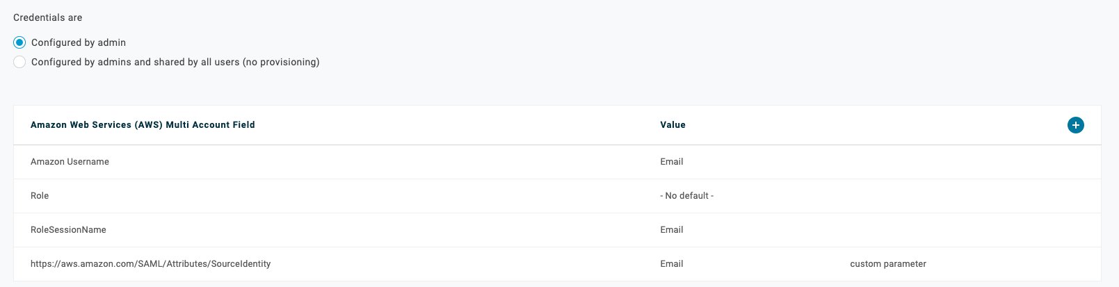
For the OneLogin SAML integration with AWS, you use the Amazon Web Services Multi Account application and configure an optional attribute to map as the SourceIdentity. You do this portion of the configuration in the OneLogin administrative console.

This procedure assumes that you already have a previously configured AWS and OneLogin integration. For information about how to configure the OneLogin application for AWS authentication and authorization, see the OneLogin KB article Configure SAML for Amazon Web Services (AWS) with Multiple Accounts and Roles.

After the OneLogin Multi Account application and AWS are correctly configured for SAML login, you can further customize the application to pass the SourceIdentity parameter upon login.

To change OneLogin configuration to add SourceIdentity attribute

  1. In the OneLogin administrative console, in the Amazon Web Services Multi Account application, on the app administration page, navigate to Parameters, as shown in Figure 8.

    Figure 8. OneLogin AWS Multi Account Application Configuration Parameters

    Figure 8. OneLogin AWS Multi Account Application Configuration Parameters

  2. To add a parameter, choose the + (plus) icon to the right of Value.
  3. As shown in Figure 9, for Field Name enter https://aws.amazon.com/SAML/Attributes/SourceIdentity, select Include in SAML assertion, then choose Save.
    Figure 9. OneLogin AWS Multi Account Application add new field

    Figure 9. OneLogin AWS Multi Account Application add new field

  4. In the Edit Field page, select the default value you want to use for SourceIdentity. For the example in this blog post, for Value, select Email, then choose Save, as shown in Figure 10.
    Figure 10. OneLogin AWS Multi Account Application map new field to email

    Figure 10. OneLogin AWS Multi Account Application map new field to email

After you’ve completed this procedure, review the final mapping details, as shown in Figure 11, to confirm that you see the additional parameter that will be passed into AWS through the SAML assertion.

Figure 11. OneLogin AWS Multi Account Application final mapping details

Figure 11. OneLogin AWS Multi Account Application final mapping details

Configuring AWS IAM role trust policy

Now that the IdP configuration is complete, you can enable your AWS accounts to use SourceIdentity by modifying the IAM role trust policy.

For the workforce identity or application to be able to define their source identity when they assume IAM roles, you must first grant them permission for the sts:SetSourceIdentity action, as illustrated in the sample policy document below. This will permit the workforce identity or application to set the SourceIdentity themselves without any need for manual intervention.

To modify an AWS IAM role trust policy

  1. Log in to the AWS Management Console for your account as a user with privileges to configure an IdP, typically an administrator.
  2. Navigate to the AWS IAM service.
  3. For trusted identity, choose SAML 2.0 federation.
  4. From the SAML Provider drop down menu, select the IAM provider you created previously.
  5. Modify the role trust policy and add the SetSourceIdentity action.

Sample policy document

This is a sample policy document attached to a role you assume when you log in to Account1 from the Okta dashboard. Edit your Account1/Role1 trust policy document and add sts:AssumeRoleWithSAML and sts:setSourceIdentity to the Action section.

{
  "Version": "2012-10-17",
  "Statement": [
    {
      "Effect": "Allow",
      "Principal": {
        "Federated": "arn:aws:iam::<AccountId>:saml-provider/<IdP>"
      },
      "Action": [
        "sts:AssumeRoleWithSAML",
        "sts:SetSourceIdentity"
      ],
      "Condition": {
        "StringEquals": {
          "SAML:aud": "https://signin.aws.amazon.com/saml"
        }
      }
    }
  ]
}

Notes: The SetSourceIdentity action has to be allowed in the trust policy for assumeRole to work when the IdP is set up to pass SourceIdentity in the assertion. Future version of the sign-in URL may contain a Region code. When this occurs, you will need to modify the URL appropriately.

Policy statement

The following are examples of how the line “Federated”: “arn:aws:iam::<AccountId>:saml-provider/<IdP>” should look, based on the different IdPs specified in this post:

  • “Federated”: “arn:aws:iam::12345678990:saml-provider/Okta”
  • “Federated”: “arn:aws:iam::12345678990:saml-provider/PingOne”
  • “Federated”: “arn:aws:iam::12345678990:saml-provider/OneLogin”

Modify Account2/Role2 policy statement

The following is a sample access control policy document in Account2 for Role2 that allows you to switchRole from Account1. Edit the control policy and add sts:AssumeRole and sts:SetSourceIdentity in the Action section.

{
  "Version": "2012-10-17",
  "Statement": [
    {
      "Effect": "Allow",
      "Principal": {
        "AWS": "arn:aws:iam::<AccountID>:root"
      },
      "Action": [
        "sts:AssumeRole",
        "sts:SetSourceIdentity"
      ] 
    }
  ]
}

Trace the SourceIdentity attribute in AWS CloudTrail

Use the following procedure for each IdP to illustrate passing a corporate directory attribute mapped as the SourceIdentity.

To trace the SourceIdentity attribute in AWS CloudTrail

  1. Use an IdP to log in to an account Account1 (111122223333) using a role named Role1.
  2. Create a new Amazon Simple Storage Service (Amazon S3) bucket in Account1.
  3. Validate that the CloudTrail log entries for Account1 contain the Active Directory mapped SourceIdentity.
  4. Use the Switch Role feature to switch to a second account Account2 (444455556666), using a role named Role2.
  5. Create a new Amazon S3 bucket in Account2.

To summarize what you’ve done so far, you have:

  • Configured your corporate directory to pass a unique attribute to AWS as the source identity.
  • Configured a role that will persist the SourceIdentity attribute in AWS STS, which an employee will use to federate into your account.
  • Configured an Amazon S3 bucket that user will access.

Now you’ll observe in CloudTrail the SourceIdentity attribute that will be associated with every IAM action.

To see the SourceIdentity attribute in CloudTrail

  1. From the your preferred IdP dashboard, select the AWS tile to log into the AWS console. The example in Figure 12 shows the Okta dashboard.
    Figure 12. Login to AWS from IdP dashboard

    Figure 12. Login to AWS from IdP dashboard

  2. Choose the AWS icon, which will take you to the AWS Management Console. Notice how the user has assumed the role you created earlier.
  3. To test the SourceIdentity action, you will create a new Amazon S3 bucket.

    Amazon S3 bucket names are globally unique, and the namespace is shared by all AWS accounts, so you will need to create a unique bucket name in your account. For this example, we used a bucket named DOC-EXAMPLE-BUCKET1 to validate CloudTrail log entries containing the SourceIdentity attribute.

  4. Log into an account Account1 (111122223333) using a role named Role1.
  5. Next, create a new Amazon S3 bucket in Account1, and validate that the Account1 CloudTrail logs entries contain the SourceIdentity attribute.
  6. Create an Amazon S3 bucket called DOC-EXAMPLE-BUCKET1, as shown in Figure 13.
    Figure 13. Create S3 bucket

    Figure 13. Create S3 bucket

  7. In the AWS Management Console go to CloudTrail and check the log entry for bucket creation event, as shown in Figure 14.
    Figure 14 - Bucket creating entry in CloudTrail

    Figure 14 – Bucket creating entry in CloudTrail

Sample CloudTrail entry showing SourceIdentity entry

The following example shows the new sourceIdentity entry added to the JSON message for the CreateBucket event above.

{"eventVersion":"1.08",
"userIdentity":{
    "type":"AssumedRole",
    "principalId":"AROA42BPHP3V5TTJH32PZ:sourceidentitytest",
    "arn":"arn:aws:sts::111122223333:assumed-role/idsol-org-admin/sourceidentitytest",
    "accountId":"111122223333",
    "accessKeyId":"ASIA42BPHP3V2QJBW7WJ",
    "sessionContext":{
        "sessionIssuer":{
            "type":"Role",
            "principalId":"AROA42BPHP3V5TTJH32PZ",
            "arn":"arn:aws:iam::111122223333:role/idsol-org-admin",
            "accountId":"111122223333","userName":"idsol-org-admin"
        },
        "webIdFederationData":{},
        "attributes":{
            "mfaAuthenticated":"false",
            "creationDate":"2021-05-05T16:29:19Z"
        },
        "sourceIdentity":"<[email protected]>"
    }
},
"eventTime":"2021-05-05T16:33:25Z",
"eventSource":"s3.amazonaws.com",
"eventName":"CreateBucket",
"awsRegion":"us-east-1",
"sourceIPAddress":"203.0.113.0"
  1. Switch to Account2 (444455556666) using assume role, and switch to Account2/assumeRoleSourceIdentity.
  2. Create a new Amazon S3 bucket in Account2 and validate that the Account2 CloudTrail log entries contain the SourceIdentity attribute, as shown in Figure 15.
    Figure 15 - Switch role to assumeRoleSourceIdentity

    Figure 15 – Switch role to assumeRoleSourceIdentity

  3. Create a new Amazon S3 bucket in account2 called DOC-EXAMPLE-BUCKET2, as shown in Figure 16.
    Figure 16 - Create DOC-EXAMPLE-BUCKET2 bucket while logged into account2 using assumeRoleSourceIdentity

    Figure 16 – Create DOC-EXAMPLE-BUCKET2 bucket while logged into account2 using assumeRoleSourceIdentity

  4. Check the CloudTrail logs for account2 (444455556666) to see if the original SourceIdentity is logged, as shown in Figure 17.
    Figure 17 - CloudTrail log entry for the above action

    Figure 17 – CloudTrail log entry for the above action

CloudTrail entry showing original SourceIdentity after assuming a role

{
    "eventVersion": "1.08",
    "userIdentity": {
        "type": "AssumedRole",
        "principalId": "AROAVC5CY2KJCIXJLPMQE:sourceidentitytest",
        "arn": "arn:aws:sts::444455556666:assumed-role/s3assumeRoleSourceIdentity/sourceidentitytest",
        "accountId": "444455556666",
        "accessKeyId": "ASIAVC5CY2KJIAO7CGA6",
        "sessionContext": {
            "sessionIssuer": {
                "type": "Role",
                "principalId": "AROAVC5CY2KJCIXJLPMQE",
                "arn": "arn:aws:iam::444455556666:role/s3assumeRoleSourceIdentity",
                "accountId": "444455556666",
                "userName": "s3assumeRoleSourceIdentity"
            },
            "webIdFederationData": {},
            "attributes": {
                "mfaAuthenticated": "false",
                "creationDate": "2021-05-05T16:47:41Z"
            },
            "sourceIdentity": "<[email protected]>"
        }
    },
    "eventTime": "2021-05-05T16:48:53Z",
    "eventSource": "s3.amazonaws.com",
    "eventName": "CreateBucket",
    "awsRegion": "us-east-1",
    "sourceIPAddress": "203.0.113.0",

You logged into Account1/Role1 and switched to Account2/Role2. All the user activities performed in AWS using the Assume Role were also logged with the original user’s sourceIdentity attribute. This makes it simple to trace user activity in CloudTrail.

Conclusion

Now that you have configured your SourceIdentity, you have made it easier for the security team of your organization to use CloudTrail logs to investigate and identify the originating identity of a user. In this post, you learned how to configure the AWS STS SourceIdentity attribute for three different popular IdPs, as well as how to configure each IdP using SAML and their optional attributes. We also provided sample control policy documents outlining how to configure the SourceIdentity for each provider. Additionally, we provide a sample policy for setting the SourceIdentity when switching roles. Lastly, the post walks through how the source identity will show in CloudTrail logs, and provides logs from two accounts to demonstrate the continuance of the source identity attribute. You can now test this capability yourself in your own environment, validate activity in your CloudTrail logs, and determine which user performed a specific action while using the assumeRole functionality.

 
If you have feedback about this post, submit comments in the Comments section below. If you have questions about this post, contact AWS Support.

Want more AWS Security news? Follow us on Twitter.

Keith Joelner

Keith Joelner

Keith is a Solution Architect at Amazon Web Services working in the ISV segment. He is based in the San Francisco Bay area. Since joining AWS in 2019, he’s been supporting Snowflake and Okta. In his spare time Keith liked woodworking and home improvement projects.

Nitin Kulkarni

Nitin is a Solutions Architect on the AWS Identity Solutions team. He helps customers build secure and scalable solutions on the AWS platform. He also enjoys hiking, baseball and linguistics.

Ramesh Kumar Venkatraman

Ramesh Kumar Venkatraman is a Solutions Architect at AWS who is passionate about containers and databases. He works with AWS customers to design, deploy and manage their AWS workloads and architectures. In his spare time, he loves to play with his two kids and follows cricket.

Eddie Esquivel

Eddie Esquivel

Eddie is a Sr. Solutions Architect in the ISV segment. He spent time at several startups focusing on Big Data and Kubernetes before joining AWS. Currently, he’s focused on management and governance and helping customers make best use of AWS technology. In his spare time he enjoys spending time outdoors with his Wife and pet dog.

Introducing Protocol buffers (protobuf) schema support in Amazon Glue Schema Registry

Post Syndicated from Vikas Bajaj original https://aws.amazon.com/blogs/big-data/introducing-protocol-buffers-protobuf-schema-support-in-amazon-glue-schema-registry/

AWS Glue Schema Registry now supports Protocol buffers (protobuf) schemas in addition to JSON and Avro schemas. This allows application teams to use protobuf schemas to govern the evolution of streaming data and centrally control data quality from data streams to data lake. AWS Glue Schema Registry provides an open-source library that includes Apache-licensed serializers and deserializers for protobuf that integrate with Java applications developed for Apache Kafka, Amazon Managed Streaming for Apache Kafka (Amazon MSK), Amazon Kinesis Data Streams, and Kafka Streams. Similar to Avro and JSON schemas, Protocol buffers schemas also support compatibility modes, schema sourcing via metadata, auto-registration of schemas, and AWS Identity and Access Management (IAM) compatibility.

In this post, we focus on Protocol buffers schema support in AWS Glue Schema Registry and how to use Protocol buffers schemas in stream processing Java applications that integrate with Apache Kafka, Amazon Managed Streaming for Apache Kafka and Amazon Kinesis Data Streams

Introduction to Protocol buffers

Protocol buffers is a language and platform-neutral, extensible mechanism for serializing and deserializing structured data for use in communications protocols and data storage. A protobuf message format is defined in the .proto file. Protobuf is recommended over other data formats when you need language interoperability, faster serialization and deserialization, type safety, schema adherence between data producer and consumer applications, and reduced coding effort. With protobuf, you can use generated code from the schema using the protobuf compiler (protoc) to easily write and read your data to and from data streams using a variety of languages. You can also use build tools plugins such as Maven and Gradle to generate code from protobuf schemas as part of your CI/CD pipelines. ​We use the following schema for code examples in this post, which defines an employee with a gRPC service definition to find an employee by ID:

Employee.proto

syntax = "proto2";
package gsr.proto.post;

import "google/protobuf/wrappers.proto";
import "google/protobuf/duration.proto";
import "google/protobuf/timestamp.proto";
import "google/type/money.proto";

service EmployeeSearch {
    rpc FindEmployee(EmployeeSearchParams) returns (Employee);
}
message EmployeeSearchParams {
    required int32 id = 1;
}
message Employee {
    required int32 id = 1;
    required string name = 2;
    required string address = 3;
    required google.protobuf.Int32Value employee_age = 4;
    required google.protobuf.Timestamp start_date = 5;
    required google.protobuf.Duration total_time_span_in_company = 6;
    required google.protobuf.BoolValue is_certified = 7;
    required Team team = 8;
    required Project project = 9;
    required Role role = 10;
    required google.type.Money total_award_value = 11;
}
message Team {
    required string name = 1;
    required string location = 2;
}
message Project {
    required string name = 1;
    required string state = 2;
}
enum Role {
    MANAGER = 0;
    DEVELOPER = 1;
    ARCHITECT = 2;
}

AWS Glue Schema Registry supports both proto2 and proto3 syntax. The preceding protobuf schema using version 2 contains three message types: Employee, Team, and Project using scalar, composite, and enumeration data types. Each field in the message definitions has a unique number, which is used to identify fields in the message binary format, and should not be changed once your message type is in use. In a proto2 message, a field can be required, optional, or repeated; in proto3, the options are repeated and optional. The package declaration makes sure generated code is namespaced to avoid any collisions. In addition to scalar, composite, and enumeration types, AWS Glue Schema Registry also supports protobuf schemas with common types such as Money, PhoneNumber,Timestamp, Duration, and nullable types such as BoolValue and Int32Value. It also supports protobuf schemas with gRPC service definitions with compatibility rules, such as EmployeeSearch, in the preceding schema. To learn more about the Protocol buffers, refer to its documentation.

Supported Protocol buffers specification and features

AWS Glue Schema Registry supports all the features of Protocol buffers for versions 2 and 3 except for groups, extensions, and importing definitions. AWS Glue Schema Registry APIs and its open-source library supports the latest protobuf runtime version. The protobuf schema operations in AWS Glue Schema Registry are supported via the AWS Management Console, AWS Command Line Interface (AWS CLI), AWS Glue Schema Registry API, AWS SDK, and AWS CloudFormation.

How AWS Glue Schema Registry works

The following diagram illustrates a high-level view of how AWS Glue Schema Registry works. AWS Glue Schema Registry allows you to register and evolve JSON, Apache Avro, and Protocol buffers schemas with compatibility modes. You can register multiple versions of each schema as the business needs or stream processing application’s requirements evolve. The AWS Glue Schema Registry open-source library provides JSON, Avro, and protobuf serializers and deserializers that you configure in producer and consumer stream processing applications, as shown in the following diagram. The open-source library also supports optional compression and caching configuration to save on data transfers.

To accommodate various business use cases, AWS Glue Schema Registry supports multiple compatibility modes. For example, if a consumer application is updated to a new schema version but is still able to consume and process messages based on the previous version of the same schema, then the schema is backward-compatible. However, if a schema version has bumped up in the producer application and the consumer application is not updated yet but can still consume and process the old and new message, then the schema is configured as forward-compatible. For more information, refer to How the Schema Registry Works.

Create a Protocol buffers schema in AWS Glue Schema Registry

In this section, we create a protobuf schema in AWS Glue Schema Registry via the console and AWS CLI.

Create a schema via the console

Make sure you have the required AWS Glue Schema Registry IAM permissions.

  1. On the AWS Glue console, choose Schema registries in the navigation pane.
  2. Click Add registry.
  3. For Registry name, enter employee-schema-registry.
  4. Click Add Registry.
  5. After the registry is created, click Add schema to register a new schema.
  6. For Schema name, enter Employee.proto.

The schema must be either Employee.proto or Employee if the protobuf schema doesn’t have the options option java_multiple_files = true; and option java_outer_classname = "<Outer class name>"; and if you decide to use protobuf schema generated code (POJOs) in your stream processing applications. We cover this with an example in a subsequent section of this post.­ For more information on protobuf options, refer to Options.

  1. For Registry, choose the registry employee-schema-registry.
  2. For Data format, choose Protocol buffers.
  3. For Compatibility mode, choose Backward.

You can choose other compatibility modes as per your use case.

  1. For First schema version, enter the preceding protobuf schema, then click Create schema and version.

After the schema is registered successfully, its status will be Available, as shown in the following screenshot.

Create a schema via the AWS CLI

Make sure you have IAM credentials with AWS Glue Schema Registry permissions.

  1. Run the following AWS CLI command to create a schema registry employee-schema-registry (for this post, we use the Region us-east-2):
    aws glue create-registry \
    --registry-name employee-schema-registry \
    --region us-east-2

The AWS CLI command returns the newly created schema registry ARN in response.

  1. Copy the RegistryArn value from the response to use in the following AWS CLI command.
  2. In the following command, use the preceding protobuf schema and schema name Employee.proto:
    aws glue create-schema --schema-name Employee.proto \
    --registry-id RegistryArn=<Schema Registry ARN that you copied from response of create registry CLI command> \
    --compatibility BACKWARD \
    --data-format PROTOBUF \
    --schema-definition file:///<project-directory>/Employee.proto \
    --region us-east-2

You can also use AWS CloudFormation to create schemas in AWS Glue Schema Registry.

Using a Protocol buffers schema with Amazon MSK and Kinesis Data Streams

Like Apache Avro’s SpecificRecord and GenericRecord, protobuf also supports working with POJOs to ensure type safety and DynamicMessage to create generic data producer and consumer applications. The following examples showcase the use of a protobuf schema registered in AWS Glue Schema Registry with Kafka and Kinesis Data Streams producer and consumer applications.

Use a protobuf schema with Amazon MSK

Create an Amazon MSK or Apache Kafka cluster with a topic called protobuf-demo-topic. If creating an Amazon MSK cluster, you can use the console. For instructions, refer to Getting Started Using Amazon MSK.

Use protobuf schema-generated POJOs

To use protobuf schema-generated POJOs, complete the following steps:

  1. Install the protobuf compiler (protoc) on your local machine from GitHub and add it in the PATH variable.
  2. Add the following plugin configuration to your application’s pom.xml file. We use the xolstice protobuf Maven plugin for this post to generate code from the protobuf schema.
    <plugin>
       <!-- https://www.xolstice.org/protobuf-maven-plugin/usage.html -->
       <groupId>org.xolstice.maven.plugins</groupId>
       <artifactId>protobuf-maven-plugin</artifactId>
       <version>0.6.1</version>
       <configuration>
           <protoSourceRoot>${basedir}/src/main/resources/proto</protoSourceRoot>
           <outputDirectory>${basedir}/src/main/java</outputDirectory>
           <clearOutputDirectory>false</clearOutputDirectory>
       </configuration>
       <executions>
           <execution>
               <goals>
                   <goal>compile</goal>
               </goals>
           </execution>
       </executions>
    </plugin>

  3. Add the following dependencies to your application’s pom.xml file:
    <!-- https://mvnrepository.com/artifact/com.google.protobuf/protobuf-java -->
    <dependency>
       <groupId>com.google.protobuf</groupId>
       <artifactId>protobuf-java</artifactId>
       <version>3.19.4</version>
    </dependency>
    
    <!-- https://mvnrepository.com/artifact/software.amazon.glue/schema-registry-serde -->
    <dependency>
       <groupId>software.amazon.glue</groupId>
       <artifactId>schema-registry-serde</artifactId>
       <version>1.1.9</version>
    </dependency>	

  4. Create a schema registry employee-schema-registry in AWS Glue Schema Registry and register the Employee.proto protobuf schema with it. Name your schema Employee.proto (or Employee).
  5. Run the following command to generate the code from Employee.proto. Make sure you have the schema file in the ${basedir}/src/main/resources/proto directory or change it as per your application directory structure in the application’s pom.xml <protoSourceRoot> tag value:
    mvn clean compile

Next, we configure the Kafka producer publishing protobuf messages to the Kafka topic on Amazon MSK.

  1. Configure the Kafka producer properties:
private Properties getProducerConfig() {
    Properties props = new Properties();
    props.put(ProducerConfig.BOOTSTRAP_SERVERS_CONFIG, this.bootstrapServers);
    props.put(ProducerConfig.KEY_SERIALIZER_CLASS_CONFIG, StringSerializer.class.getName());
    props.put(ProducerConfig.VALUE_SERIALIZER_CLASS_CONFIG, GlueSchemaRegistryKafkaSerializer.class.getName());
    props.put(AWSSchemaRegistryConstants.DATA_FORMAT, DataFormat.PROTOBUF.name());
    props.put(AWSSchemaRegistryConstants.AWS_REGION,"us-east-2");
    props.put(AWSSchemaRegistryConstants.REGISTRY_NAME, "employee-schema-registry");
    props.put(AWSSchemaRegistryConstants.SCHEMA_NAME, "Employee.proto");
    props.put(AWSSchemaRegistryConstants.PROTOBUF_MESSAGE_TYPE, ProtobufMessageType.POJO.getName());
    return props;
}

The VALUE_SERIALIZER_CLASS_CONFIG configuration specifies the AWS Glue Schema Registry serializer, which serializes the protobuf message.

  1. Use the schema-generated code (POJOs) to create a protobuf message:
    public EmployeeOuterClass.Employee createEmployeeRecord(int employeeId){
        EmployeeOuterClass.Employee employee =
                EmployeeOuterClass.Employee.newBuilder()
                        .setId(employeeId)
                        .setName("Dummy")
                        .setAddress("Melbourne, Australia")
                        .setEmployeeAge(Int32Value.newBuilder().setValue(32).build())
                        .setStartDate(Timestamp.newBuilder().setSeconds(235234532434L).build())
                        .setTotalTimeSpanInCompany(Duration.newBuilder().setSeconds(3453245345L).build())
                        .setIsCertified(BoolValue.newBuilder().setValue(true).build())
                        .setRole(EmployeeOuterClass.Role.ARCHITECT)
                        .setProject(EmployeeOuterClass.Project.newBuilder()
                                .setName("Protobuf Schema Demo")
                                .setState("GA").build())
                        .setTotalAwardValue(Money.newBuilder()
                                            .setCurrencyCode("USD")
                                            .setUnits(5)
                                            .setNanos(50000).build())
                        .setTeam(EmployeeOuterClass.Team.newBuilder()
                                .setName("Solutions Architects")
                                .setLocation("Australia").build()).build();
        return employee;
    }

  2. Publish the protobuf messages to the protobuf-demo-topic topic on Amazon MSK:
    public void startProducer() throws InterruptedException {
        String topic = "protobuf-demo-topic";
        KafkaProducer<String, EmployeeOuterClass.Employee> producer = new KafkaProducer<String, EmployeeOuterClass.Employee>(getProducerConfig());
        logger.info("Starting to send records...");
        int employeeId = 0;
        while(employeeId < 100)
        {
            EmployeeOuterClass.Employee person = createEmployeeRecord(employeeId);
            String key = "key-" + employeeId;
            ProducerRecord<String,  EmployeeOuterClass.Employee> record = new ProducerRecord<String,  EmployeeOuterClass.Employee>(topic, key, person);
            producer.send(record, new ProducerCallback());
            employeeId++;
        }
    }
    private class ProducerCallback implements Callback {
        @Override
        public void onCompletion(RecordMetadata recordMetaData, Exception e){
            if (e == null) {
                logger.info("Received new metadata. \n" +
                        "Topic:" + recordMetaData.topic() + "\n" +
                        "Partition: " + recordMetaData.partition() + "\n" +
                        "Offset: " + recordMetaData.offset() + "\n" +
                        "Timestamp: " + recordMetaData.timestamp());
            }
            else {
                logger.info("There's been an error from the Producer side");
                e.printStackTrace();
            }
        }
    }

  3. Start the Kafka producer:
    public static void main(String args[]) throws InterruptedException {
        ProducerProtobuf producer = new ProducerProtobuf();
        producer.startProducer();
    }

  4. In the Kafka consumer application’s pom.xml, add the same plugin and dependencies as the Kafka producer’s pom.xml.

Next, we configure the Kafka consumer consuming protobuf messages from the Kafka topic on Amazon MSK.

  1. Configure the Kafka consumer properties:
    private Properties getConsumerConfig() {
        Properties props = new Properties();
        props.put(ProducerConfig.BOOTSTRAP_SERVERS_CONFIG, this.bootstrapServers);
        props.put(ConsumerConfig.GROUP_ID_CONFIG, "protobuf-consumer");
        props.put(ConsumerConfig.AUTO_OFFSET_RESET_CONFIG,"earliest");
        props.put(ConsumerConfig.KEY_DESERIALIZER_CLASS_CONFIG, StringDeserializer.class.getName());
        props.put(ConsumerConfig.VALUE_DESERIALIZER_CLASS_CONFIG, GlueSchemaRegistryKafkaDeserializer.class.getName());
        props.put(AWSSchemaRegistryConstants.AWS_REGION,"us-east-2");
        props.put(AWSSchemaRegistryConstants.PROTOBUF_MESSAGE_TYPE, ProtobufMessageType.POJO.getName());
        return props;
    }

The VALUE_DESERIALIZER_CLASS_CONFIG config specifies the AWS Glue Schema Registry deserializer that deserializes the protobuf messages.

  1. Consume the protobuf message (as a POJO) from the protobuf-demo-topic topic on Amazon MSK:
    public void startConsumer() {
        logger.info("starting consumer...");
        String topic = "protobuf-demo-topic";
        KafkaConsumer<String, EmployeeOuterClass.Employee> consumer = new KafkaConsumer<String, EmployeeOuterClass.Employee>(getConsumerConfig());
        consumer.subscribe(Collections.singletonList(topic));
        while (true) {
            final ConsumerRecords<String, EmployeeOuterClass.Employee> records = consumer.poll(Duration.ofMillis(1000));
            for (final ConsumerRecord<String, EmployeeOuterClass.Employee> record : records) {
                final EmployeeOuterClass.Employee employee = record.value();
                logger.info("Employee Id: " + employee.getId() + " | Name: " + employee.getName() + " | Address: " + employee.getAddress() +
                        " | Age: " + employee.getEmployeeAge().getValue() + " | Startdate: " + employee.getStartDate().getSeconds() +
                        " | TotalTimeSpanInCompany: " + employee.getTotalTimeSpanInCompany() +
                        " | IsCertified: " + employee.getIsCertified().getValue() + " | Team: " + employee.getTeam().getName() +
                        " | Role: " + employee.getRole().name() + " | Project State: " + employee.getProject().getState() +
                        " | Project Name: " + employee.getProject().getName() + "| Award currency code: " + employee.getTotalAwardValue().getCurrencyCode() +
                        " | Award units : " + employee.getTotalAwardValue().getUnits() + " | Award nanos " + employee.getTotalAwardValue().getNanos());
            }
        }
    }

  2. Start the Kafka consumer:
    public static void main(String args[]){
        ConsumerProtobuf consumer = new ConsumerProtobuf();
        consumer.startConsumer();
    }

Use protobuf’s DynamicMessage

You can use DynamicMessage to create generic producer and consumer applications without generating the code from the protobuf schema. To use DynamicMessage, you first need to create a protobuf schema file descriptor.

  1. Generate a file descriptor from the protobuf schema using the following command:
    protoc --include_imports --proto_path=proto --descriptor_set_out=proto/Employeeproto.desc proto/Employee.proto

The option --descritor_set_out has the descriptor file name that this command generates. The protobuf schema Employee.proto is in the proto directory.

  1. Make sure you have created a schema registry and registered the preceding protobuf schema with it.

Now we configure the Kafka producer publishing DynamicMessage to the Kafka topic on Amazon MSK.

  1. Create the Kafka producer configuration. The PROTOBUF_MESSAGE_TYPE configuration is DYNAMIC_MESSAGE instead of POJO.
    private Properties getProducerConfig() {
       Properties props = new Properties();
       props.put(ProducerConfig.BOOTSTRAP_SERVERS_CONFIG, this.bootstrapServers);
       props.put(ProducerConfig.ACKS_CONFIG, "-1");
       props.put(ProducerConfig.CLIENT_ID_CONFIG,"protobuf-dynamicmessage-record-producer");
       props.put(ProducerConfig.KEY_SERIALIZER_CLASS_CONFIG, StringSerializer.class.getName());
       props.put(ProducerConfig.VALUE_SERIALIZER_CLASS_CONFIG,GlueSchemaRegistryKafkaSerializer.class.getName());
       props.put(AWSSchemaRegistryConstants.DATA_FORMAT, DataFormat.PROTOBUF.name());
       props.put(AWSSchemaRegistryConstants.AWS_REGION,"us-east-2");
       props.put(AWSSchemaRegistryConstants.REGISTRY_NAME, "employee-schema-registry");
       props.put(AWSSchemaRegistryConstants.SCHEMA_NAME, "Employee.proto");
       props.put(AWSSchemaRegistryConstants.PROTOBUF_MESSAGE_TYPE, ProtobufMessageType.DYNAMIC_MESSAGE.getName());
       return props;
        }

  2. Create protobuf dynamic messages and publish them to the Kafka topic on Amazon MSK:
    public void startProducer() throws Exception {
        Descriptor desc = getDescriptor();
        String topic = "protobuf-demo-topic";
        KafkaProducer<String, DynamicMessage> producer = new KafkaProducer<String, DynamicMessage>(getProducerConfig());
        logger.info("Starting to send records...");
        int i = 0;
        while (i < 100) {
            DynamicMessage dynMessage = DynamicMessage.newBuilder(desc)
                    .setField(desc.findFieldByName("id"), 1234)
                    .setField(desc.findFieldByName("name"), "Dummy Name")
                    .setField(desc.findFieldByName("address"), "Melbourne, Australia")
                    .setField(desc.findFieldByName("employee_age"), Int32Value.newBuilder().setValue(32).build())
                    .setField(desc.findFieldByName("start_date"), Timestamp.newBuilder().setSeconds(235234532434L).build())
                    .setField(desc.findFieldByName("total_time_span_in_company"), Duration.newBuilder().setSeconds(3453245345L).build())
                    .setField(desc.findFieldByName("is_certified"), BoolValue.newBuilder().setValue(true).build())
    		.setField(desc.findFieldByName("total_award_value"), Money.newBuilder().setCurrencyCode("USD")
    						.setUnits(1).setNanos(50000).build())
                    .setField(desc.findFieldByName("team"), createTeam(desc.findFieldByName("team").getMessageType()))
                    .setField(desc.findFieldByName("project"), createProject(desc.findFieldByName("project").getMessageType()))
                    .setField(desc.findFieldByName("role"), desc.findFieldByName("role").getEnumType().findValueByName("ARCHITECT"))
                    .build();
            String key = "key-" + i;
            ProducerRecord<String, DynamicMessage> record = new ProducerRecord<String, DynamicMessage>(topic, key, dynMessage);
            producer.send(record, new ProtobufProducer.ProducerCallback());
            Thread.sleep(1000);
            i++;
        }
    }
    private static DynamicMessage createTeam(Descriptor desc) {
        DynamicMessage dynMessage = DynamicMessage.newBuilder(desc)
                .setField(desc.findFieldByName("name"), "Solutions Architects")
                .setField(desc.findFieldByName("location"), "Australia")
                .build();
        return dynMessage;
    }
    
    private static DynamicMessage createProject(Descriptor desc) {
        DynamicMessage dynMessage = DynamicMessage.newBuilder(desc)
                .setField(desc.findFieldByName("name"), "Protobuf Schema Demo")
                .setField(desc.findFieldByName("state"), "GA")
                .build();
        return dynMessage;
    }
    
    private class ProducerCallback implements Callback {
        @Override
        public void onCompletion(RecordMetadata recordMetaData, Exception e) {
            if (e == null) {
                logger.info("Received new metadata. \n" +
                        "Topic:" + recordMetaData.topic() + "\n" +
                        "Partition: " + recordMetaData.partition() + "\n" +
                        "Offset: " + recordMetaData.offset() + "\n" +
                        "Timestamp: " + recordMetaData.timestamp());
            } else {
                logger.info("There's been an error from the Producer side");
                e.printStackTrace();
            }
        }
    }

  3. Create a descriptor using the Employeeproto.desc file that we generated from the Employee.proto schema file in the previous steps:
    private Descriptor getDescriptor() throws Exception {
        InputStream inStream = ProtobufProducer.class.getClassLoader().getResourceAsStream("proto/Employeeproto.desc");
        DescriptorProtos.FileDescriptorSet fileDescSet = DescriptorProtos.FileDescriptorSet.parseFrom(inStream);
        Map<String, DescriptorProtos.FileDescriptorProto> fileDescProtosMap = new HashMap<String, DescriptorProtos.FileDescriptorProto>();
        List<DescriptorProtos.FileDescriptorProto> fileDescProtos = fileDescSet.getFileList();
        for (DescriptorProtos.FileDescriptorProto fileDescProto : fileDescProtos) {
            fileDescProtosMap.put(fileDescProto.getName(), fileDescProto);
        }
        DescriptorProtos.FileDescriptorProto fileDescProto = fileDescProtosMap.get("Employee.proto");
        FileDescriptor[] dependencies = getProtoDependencies(fileDescProtosMap, fileDescProto);
        FileDescriptor fileDesc = FileDescriptor.buildFrom(fileDescProto, dependencies);
        Descriptor desc = fileDesc.findMessageTypeByName("Employee");
        return desc;
    }
    
    public static FileDescriptor[] getProtoDependencies(Map<String, FileDescriptorProto> fileDescProtos, 
    				  FileDescriptorProto fileDescProto) throws Exception {
    
        if (fileDescProto.getDependencyCount() == 0)
            return new FileDescriptor[0];
    
        ProtocolStringList dependencyList = fileDescProto.getDependencyList();
        String[] dependencyArray = dependencyList.toArray(new String[0]);
        int noOfDependencies = dependencyList.size();
    
        FileDescriptor[] dependencies = new FileDescriptor[noOfDependencies];
        for (int i = 0; i < noOfDependencies; i++) {
            FileDescriptorProto dependencyFileDescProto = fileDescProtos.get(dependencyArray[i]);
            FileDescriptor dependencyFileDesc = FileDescriptor.buildFrom(dependencyFileDescProto, 
    					     getProtoDependencies(fileDescProtos, dependencyFileDescProto));
            dependencies[i] = dependencyFileDesc;
        }
        return dependencies;
    }

  4. Start the Kafka producer:
    public static void main(String args[]) throws InterruptedException {
    	 ProducerProtobuf producer = new ProducerProtobuf();
             producer.startProducer();
    }

Now we configure the Kafka consumer consuming dynamic messages from the Kaka topic on Amazon MSK.

  1. Enter the following Kafka consumer configuration:
    private Properties getConsumerConfig() {
        Properties props = new Properties();
        props.put(ProducerConfig.BOOTSTRAP_SERVERS_CONFIG, this.bootstrapServers);
        props.put(ConsumerConfig.GROUP_ID_CONFIG, "protobuf-record-consumer");
        props.put(ConsumerConfig.AUTO_OFFSET_RESET_CONFIG,"earliest");
        props.put(ConsumerConfig.KEY_DESERIALIZER_CLASS_CONFIG, StringDeserializer.class.getName());
        props.put(ConsumerConfig.VALUE_DESERIALIZER_CLASS_CONFIG, GlueSchemaRegistryKafkaDeserializer.class.getName());
        props.put(AWSSchemaRegistryConstants.AWS_REGION,"us-east-2");
        props.put(AWSSchemaRegistryConstants.PROTOBUF_MESSAGE_TYPE, ProtobufMessageType.DYNAMIC_MESSAGE.getName());
        return props;
    }

  2. Consume protobuf dynamic messages from the Kafka topic protobuf-demo-topic. Because we’re using DYNAMIC_MESSAGE, the retrieved objects are of type DynamicMessage.
    public void startConsumer() {
        logger.info("starting consumer...");
        String topic = "protobuf-demo-topic";
        KafkaConsumer<String, DynamicMessage> consumer = new KafkaConsumer<String, DynamicMessage>(getConsumerConfig());
        consumer.subscribe(Collections.singletonList(topic));
        while (true) {
            final ConsumerRecords<String, DynamicMessage> records = consumer.poll(Duration.ofMillis(1000));
            for (final ConsumerRecord<String, DynamicMessage> record : records) {
                for (Descriptors.FieldDescriptor field : record.value().getAllFields().keySet()) {
                    logger.info(field.getName() + ": " + record.value().getField(field));
                }
            }
        }
    }

  3. Start the Kafka consumer:
    public static void main(String args[]){
            ConsumerProtobuf consumer = new ConsumerProtobuf();
            consumer.startConsumer();
         }

Use a protobuf schema with Kinesis Data Streams

You can use the protobuf schema-generated POJOs with the Kinesis Producer Library (KPL) and Kinesis Client Library (KCL).

  1. Install the protobuf compiler (protoc) on your local machine from GitHub and add it in the PATH variable.
  2. Add the following plugin configuration to your application’s pom.xml file. We’re using the xolstice protobuf Maven plugin for this post to generate code from the protobuf schema.
    <plugin>
       <!-- https://www.xolstice.org/protobuf-maven-plugin/usage.html -->
       <groupId>org.xolstice.maven.plugins</groupId>
       <artifactId>protobuf-maven-plugin</artifactId>
       <version>0.6.1</version>
       <configuration>
           <protoSourceRoot>${basedir}/src/main/resources/proto</protoSourceRoot>
           <outputDirectory>${basedir}/src/main/java</outputDirectory>
           <clearOutputDirectory>false</clearOutputDirectory>
       </configuration>
       <executions>
           <execution>
               <goals>
                   <goal>compile</goal>
               </goals>
           </execution>
       </executions>
    </plugin>

  3. Because the KPL and KCL latest versions have the AWS Glue Schema Registry open-source library (schema-registry-serde) and protobuf runtime (protobuf-java) included, you only need to add the following dependencies to your application’s pom.xml:
    <!-- https://mvnrepository.com/artifact/com.amazonaws/amazon-kinesis-producer -->
    <dependency>
        <groupId>com.amazonaws</groupId>
        <artifactId>amazon-kinesis-producer</artifactId>
        <version>0.14.11</version>
    	</dependency>
    	<!-- https://mvnrepository.com/artifact/software.amazon.kinesis/amazon-kinesis-client -->
    <dependency>
        <groupId>software.amazon.kinesis</groupId>
        <artifactId>amazon-kinesis-client</artifactId>
        <version>2.4.0version>
    </dependency>

  4. Create a schema registry employee-schema-registry and register the Employee.proto protobuf schema with it. Name your schema Employee.proto (or Employee).
  5. Run the following command to generate the code from Employee.proto. Make sure you have the schema file in the ${basedir}/src/main/resources/proto directory or change it as per your application directory structure in the application’s pom.xml <protoSourceRoot> tag value.
    mvn clean compile

The following Kinesis producer code with the KPL uses the Schema Registry open-source library to publish protobuf messages to Kinesis Data Streams.

  1. Start the Kinesis Data Streams producer:
    private static final String PROTO_SCHEMA_FILE = "proto/Employee.proto";
    private static final String SCHEMA_NAME = "Employee.proto";
    private static String REGION_NAME = "us-east-2";
    private static String REGISTRY_NAME = "employee-schema-registry";
    private static String STREAM_NAME = "employee_data_stream";
    private static int NUM_OF_RECORDS = 100;
    private static String REGISTRY_ENDPOINT = "https://glue.us-east-2.amazonaws.com";
    
    public static void main(String[] args) throws Exception {
         ProtobufKPLProducer producer = new ProtobufKPLProducer();
         producer.startProducer();
     }
    }

  2. Configure the Kinesis producer:
public void startProducer() throws Exception {
    logger.info("Starting KPL client with Glue Schema Registry Integration...");
    GlueSchemaRegistryConfiguration schemaRegistryConfig = new GlueSchemaRegistryConfiguration(REGION_NAME);
    schemaRegistryConfig.setCompressionType(AWSSchemaRegistryConstants.COMPRESSION.ZLIB);
    schemaRegistryConfig.setSchemaAutoRegistrationEnabled(false);
    schemaRegistryConfig.setCompatibilitySetting(Compatibility.BACKWARD);
    schemaRegistryConfig.setEndPoint(REGISTRY_ENDPOINT);
    schemaRegistryConfig.setProtobufMessageType(ProtobufMessageType.POJO);
    schemaRegistryConfig.setRegistryName(REGISTRY_NAME);
	
    //Setting Glue Schema Registry configuration in Kinesis Producer Configuration along with other configs
    KinesisProducerConfiguration config = new KinesisProducerConfiguration()
                                        .setRecordMaxBufferedTime(3000)
                                        .setMaxConnections(1)
                                        .setRequestTimeout(60000)
                                        .setRegion(REGION_NAME)
                                        .setRecordTtl(60000)
                                        .setGlueSchemaRegistryConfiguration(schemaRegistryConfig);

    FutureCallback<UserRecordResult> myCallback = new FutureCallback<UserRecordResult>() {
        @Override public void onFailure(Throwable t) {
              t.printStackTrace();
        };
        @Override public void onSuccess(UserRecordResult result) {
            logger.info("record sent successfully. Sequence Number: " + result.getSequenceNumber() + " | Shard Id : " + result.getShardId());
        };
    };
    
	//Creating schema definition object from the Employee.proto schema file.
    Schema gsrSchema = getSchemaDefinition();
    final KinesisProducer producer = new KinesisProducer(config);
    int employeeCount = 1;
    while(true) {
        //Creating and serializing schema generated POJO object (protobuf message)

        EmployeeOuterClass.Employee employee = createEmployeeRecord(employeeCount);
        byte[] serializedBytes = employee.toByteArray();
        ByteBuffer data = ByteBuffer.wrap(serializedBytes);
        Instant timestamp = Instant.now();

        //Publishing protobuf message to the Kinesis Data Stream
        ListenableFuture<UserRecordResult> f =
                    producer.addUserRecord(STREAM_NAME,
                                        Long.toString(timestamp.toEpochMilli()),
                                        new BigInteger(128, new Random()).toString(10),
                                        data,
                                        gsrSchema);
        Futures.addCallback(f, myCallback, MoreExecutors.directExecutor());
        employeeCount++;
        if(employeeCount > NUM_OF_RECORDS)
            break;
    }
    List<Future<UserRecordResult>> putFutures = new LinkedList<>();
    for (Future<UserRecordResult> future : putFutures) {
        UserRecordResult userRecordResult = future.get();
        logger.info(userRecordResult.getShardId() + userRecordResult.getSequenceNumber());
    }
}
  1. Create a protobuf message using schema-generated code (POJOs):
    public EmployeeOuterClass.Employee createEmployeeRecord(int count){
        EmployeeOuterClass.Employee employee =
                EmployeeOuterClass.Employee.newBuilder()
                .setId(count)
                .setName("Dummy")
                .setAddress("Melbourne, Australia")
                .setEmployeeAge(Int32Value.newBuilder().setValue(32).build())
                .setStartDate(Timestamp.newBuilder().setSeconds(235234532434L).build())
                .setTotalTimeSpanInCompany(Duration.newBuilder().setSeconds(3453245345L).build())
                .setIsCertified(BoolValue.newBuilder().setValue(true).build())
                .setRole(EmployeeOuterClass.Role.ARCHITECT)
                .setProject(EmployeeOuterClass.Project.newBuilder()
                            .setName("Protobuf Schema Demo")
                            .setState("GA").build())
                .setTotalAwardValue(Money.newBuilder()
                            .setCurrencyCode("USD")
                            .setUnits(5)
                            .setNanos(50000).build())
                .setTeam(EmployeeOuterClass.Team.newBuilder()
                            .setName("Solutions Architects")
                            .setLocation("Australia").build()).build();
        return employee;
    }

  2. Create the schema definition from Employee.proto:
    private Schema getSchemaDefinition() throws IOException {
        InputStream inputStream = ProtobufKPLProducer.class.getClassLoader().getResourceAsStream(PROTO_SCHEMA_FILE);
        StringBuilder resultStringBuilder = new StringBuilder();
        try (BufferedReader br = new BufferedReader(new InputStreamReader(inputStream))) {
            String line;
            while ((line = br.readLine()) != null) {
                resultStringBuilder.append(line).append("\n");
            }
        }
        String schemaDefinition = resultStringBuilder.toString();
        logger.info("Schema Definition " + schemaDefinition);
        Schema gsrSchema =
                new Schema(schemaDefinition, DataFormat.PROTOBUF.toString(), SCHEMA_NAME);
        return gsrSchema;
    }

The following is the Kinesis consumer code with the KCL using the Schema Registry open-source library to consume protobuf messages from the Kinesis Data Streams.

  1. Initialize the application:
    public void run(){
        logger.info("Starting KCL client with Glue Schema Registry Integration...");
        Region region = Region.of(ObjectUtils.firstNonNull(REGION_NAME, "us-east-2"));
        KinesisAsyncClient kinesisClient = KinesisClientUtil.createKinesisAsyncClient(KinesisAsyncClient.builder().region(region));
        DynamoDbAsyncClient dynamoClient = DynamoDbAsyncClient.builder().region(region).build();
        CloudWatchAsyncClient cloudWatchClient = CloudWatchAsyncClient.builder().region(region).build();
    
        EmployeeRecordProcessorFactory employeeRecordProcessorFactory = new EmployeeRecordProcessorFactory();
        ConfigsBuilder configsBuilder =
                new ConfigsBuilder(STREAM_NAME,
                        APPLICATION_NAME,
                        kinesisClient,
                        dynamoClient,
                        cloudWatchClient,
                        APPLICATION_NAME,
                        employeeRecordProcessorFactory);
    
        //Creating Glue Schema Registry configuration and Glue Schema Registry Deserializer object.
        GlueSchemaRegistryConfiguration gsrConfig = new GlueSchemaRegistryConfiguration(region.toString());
        gsrConfig.setEndPoint(REGISTRY_ENDPOINT);
        gsrConfig.setProtobufMessageType(ProtobufMessageType.POJO);
        GlueSchemaRegistryDeserializer glueSchemaRegistryDeserializer =
                new GlueSchemaRegistryDeserializerImpl(DefaultCredentialsProvider.builder().build(), gsrConfig);
        /*
         Setting Glue Schema Registry deserializer in the Retrieval Config for
         Kinesis Client Library to use it while deserializing the protobuf messages.
         */
        RetrievalConfig retrievalConfig = configsBuilder.retrievalConfig().retrievalSpecificConfig(new PollingConfig(STREAM_NAME, kinesisClient));
        retrievalConfig.glueSchemaRegistryDeserializer(glueSchemaRegistryDeserializer);
    
        Scheduler scheduler = new Scheduler(
                		configsBuilder.checkpointConfig(),
                		configsBuilder.coordinatorConfig(),
               		configsBuilder.leaseManagementConfig(),
                		configsBuilder.lifecycleConfig(),
                		configsBuilder.metricsConfig(),
                		configsBuilder.processorConfig(),
                		retrievalConfig);
    
        Thread schedulerThread = new Thread(scheduler);
        schedulerThread.setDaemon(true);
        schedulerThread.start();
    
        logger.info("Press enter to shutdown");
        BufferedReader reader = new BufferedReader(new InputStreamReader(System.in));
        try {
            reader.readLine();
            Future<Boolean> gracefulShutdownFuture = scheduler.startGracefulShutdown();
            logger.info("Waiting up to 20 seconds for shutdown to complete.");
            gracefulShutdownFuture.get(20, TimeUnit.SECONDS);
        } catch (Exception e) {
            logger.info("Interrupted while waiting for graceful shutdown. Continuing.");
        }
        logger.info("Completed, shutting down now.");
    }

  2. Consume protobuf messages from Kinesis Data Streams:
    public static class EmployeeRecordProcessorFactory implements ShardRecordProcessorFactory {
        @Override
        public ShardRecordProcessor shardRecordProcessor() {
            return new EmployeeRecordProcessor();
        }
    }
    public static class EmployeeRecordProcessor implements ShardRecordProcessor {
        private static final Logger logger = Logger.getLogger(EmployeeRecordProcessor.class.getSimpleName());
        public void initialize(InitializationInput initializationInput) {}
        public void processRecords(ProcessRecordsInput processRecordsInput) {
            try {
                logger.info("Processing " + processRecordsInput.records().size() + " record(s)");
                for (KinesisClientRecord r : processRecordsInput.records()) {
    			
                    //Deserializing protobuf message into schema generated POJO
                    EmployeeOuterClass.Employee employee = EmployeeOuterClass.Employee.parseFrom(r.data().array());
                    
                   logger.info("Processed record: " + employee);
                    logger.info("Employee Id: " + employee.getId() + " | Name: "  + employee.getName() + " | Address: " + employee.getAddress() +
                            " | Age: " + employee.getEmployeeAge().getValue() + " | Startdate: " + employee.getStartDate().getSeconds() +
                            " | TotalTimeSpanInCompany: " + employee.getTotalTimeSpanInCompany() +
                            " | IsCertified: " + employee.getIsCertified().getValue() + " | Team: " + employee.getTeam().getName() +
                            " | Role: " + employee.getRole().name() + " | Project State: " + employee.getProject().getState() +
                            " | Project Name: " + employee.getProject().getName() + " | Award currency code: " +    
                           employee.getTotalAwardValue().getCurrencyCode() + " | Award units : " + employee.getTotalAwardValue().getUnits() + 
    		      " | Award nanos " + employee.getTotalAwardValue().getNanos());
                }
            } catch (Exception e) {
                logger.info("Failed while processing records. Aborting" + e);
                Runtime.getRuntime().halt(1);
            }
        }
        public void leaseLost(LeaseLostInput leaseLostInput) {. . .}
        public void shardEnded(ShardEndedInput shardEndedInput) {. . .}
        public void shutdownRequested(ShutdownRequestedInput shutdownRequestedInput) {. . .}
    }

  3. Start the Kinesis Data Streams consumer:
    private static final Logger logger = Logger.getLogger(ProtobufKCLConsumer.class.getSimpleName());
    private static String REGION_NAME = "us-east-2";
    private static String STREAM_NAME = "employee_data_stream";
    private static final String APPLICATION_NAME =  "protobuf-demo-kinesis-kpl-consumer";
    private static String REGISTRY_ENDPOINT = "https://glue.us-east-2.amazonaws.com";
    
    public static void main(String[] args) throws ParseException {
        new ProtobufKCLConsumer().run();
    }
    

Enhance your protobuf schema

We covered examples of data producer and consumer applications integrating with Amazon MSK, Apache Kafka, and Kinesis Data Streams, and using a Protocol buffers schema registered with AWS Glue Schema Registry. You can further enhance these examples with schema evolution using the following rules, which are supported by AWS Glue Schema Registry. For example, the following protobuf schema shown is a backward-compatible updated version of Employee.proto. We have added another gRPC service definition CreateEmployee under EmployeeSearch and added an Optional field in the Employee message type. If you upgrade the consumer application with this version of the protobuf schema, the consumer application can still consume old and new protobuf messages.

Employee.proto (version-2)

syntax = "proto2";
package gsr.proto.post;

import "google/protobuf/wrappers.proto";
import "google/protobuf/duration.proto";
import "google/protobuf/timestamp.proto";
import "google/protobuf/empty.proto";
import "google/type/money.proto";

service EmployeeSearch {
    rpc FindEmployee(EmployeeSearchParams) returns (Employee);
    rpc CreateEmployee(EmployeeSearchParams) returns (google.protobuf.Empty);
}
message EmployeeSearchParams {
    required int32 id = 1;
}
message Employee {
    required int32 id = 1;
    required string name = 2;
    required string address = 3;
    required google.protobuf.Int32Value employee_age = 4;
    required google.protobuf.Timestamp start_date = 5;
    required google.protobuf.Duration total_time_span_in_company = 6;
    required google.protobuf.BoolValue is_certified = 7;
    required Team team = 8;
    required Project project = 9;
    required Role role = 10;
    required google.type.Money total_award_value = 11;
    optional string title = 12;
}
message Team {
    required string name = 1;
    required string location = 2;
}
message Project {
    required string name = 1;
    required string state = 2;
}
enum Role {
    MANAGER = 0;
    DEVELOPER = 1;
    ARCHITECT = 2;
}

Conclusion

In this post, we introduced Protocol buffers schema support in AWS Glue Schema Registry. AWS Glue Schema Registry now supports Apache Avro, JSON, and Protocol buffers schemas with different compatible modes. The examples in this post demonstrated how to use Protocol buffers schemas registered with AWS Glue Schema Registry in stream processing applications integrated with Apache Kafka, Amazon MSK, and Kinesis Data Streams. We used the schema-generated POJOs for type safety and protobuf’s DynamicMessage to create generic producer and consumer applications. The examples in this post contain the basic components of the stream processing pattern; you can adapt these examples to your use case needs.

To learn more, refer to the following resources:


About the Author

Vikas Bajaj is a Principal Solutions Architect at AWS. Vikas works with digital native customers and advises them on technology architecture and solutions to meet strategic business objectives.

Best practices: Securing your Amazon Location Service resources

Post Syndicated from Dave Bailey original https://aws.amazon.com/blogs/security/best-practices-securing-your-amazon-location-service-resources/

Location data is subjected to heavy scrutiny by security experts. Knowing the current position of a person, vehicle, or asset can provide industries with many benefits, whether to understand where a current delivery is, how many people are inside a venue, or to optimize routing for a fleet of vehicles. This blog post explains how Amazon Web Services (AWS) helps keep location data secured in transit and at rest, and how you can leverage additional security features to help keep information safe and compliant.

The General Data Protection Regulation (GDPR) defines personal data as “any information relating to an identified or identifiable natural person (…) such as a name, an identification number, location data, an online identifier or to one or more factors specific to the physical, physiological, genetic, mental, economic, cultural or social identity of that natural person.” Also, many companies wish to improve transparency to users, making it explicit when a particular application wants to not only track their position and data, but also to share that information with other apps and websites. Your organization needs to adapt to these changes quickly to maintain a secure stance in a competitive environment.

On June 1, 2021, AWS made Amazon Location Service generally available to customers. With Amazon Location, you can build applications that provide maps and points of interest, convert street addresses into geographic coordinates, calculate routes, track resources, and invoke actions based on location. The service enables you to access location data with developer tools and to move your applications to production faster with monitoring and management capabilities.

In this blog post, we will show you the features that Amazon Location provides out of the box to keep your data safe, along with best practices that you can follow to reach the level of security that your organization strives to accomplish.

Data control and data rights

Amazon Location relies on global trusted providers Esri and HERE Technologies to provide high-quality location data to customers. Features like maps, places, and routes are provided by these AWS Partners so solutions can have data that is not only accurate but constantly updated.

AWS anonymizes and encrypts location data at rest and during its transmission to partner systems. In parallel, third parties cannot sell your data or use it for advertising purposes, following our service terms. This helps you shield sensitive information, protect user privacy, and reduce organizational compliance risks. To learn more, see the Amazon Location Data Security and Control documentation.

Integrations

Operationalizing location-based solutions can be daunting. It’s not just necessary to build the solution, but also to integrate it with the rest of your applications that are built in AWS. Amazon Location facilitates this process from a security perspective by integrating with services that expedite the development process, enhancing the security aspects of the solution.

Encryption

Amazon Location uses AWS owned keys by default to automatically encrypt personally identifiable data. AWS owned keys are a collection of AWS Key Management Service (AWS KMS) keys that an AWS service owns and manages for use in multiple AWS accounts. Although AWS owned keys are not in your AWS account, Amazon Location can use the associated AWS owned keys to protect the resources in your account.

If customers choose to use their own keys, they can benefit from AWS KMS to store their own encryption keys and use them to add a second layer of encryption to geofencing and tracking data.

Authentication and authorization

Amazon Location also integrates with AWS Identity and Access Management (IAM), so that you can use its identity-based policies to specify allowed or denied actions and resources, as well as the conditions under which actions are allowed or denied on Amazon Location. Also, for actions that require unauthenticated access, you can use unauthenticated IAM roles.

As an extension to IAM, Amazon Cognito can be an option if you need to integrate your solution with a front-end client that authenticates users with its own process. In this case, you can use Cognito to handle the authentication, authorization, and user management for you. You can use Cognito unauthenticated identity pools with Amazon Location as a way for applications to retrieve temporary, scoped-down AWS credentials. To learn more about setting up Cognito with Amazon Location, see the blog post Add a map to your webpage with Amazon Location Service.

Limit the scope of your unauthenticated roles to a domain

When you are building an application that allows users to perform actions such as retrieving map tiles, searching for points of interest, updating device positions, and calculating routes without needing them to be authenticated, you can make use of unauthenticated roles.

When using unauthenticated roles to access Amazon Location resources, you can add an extra condition to limit resource access to an HTTP referer that you specify in the policy. The aws:referer request context value is provided by the caller in an HTTP header, and it is included in a web browser request.

The following is an example of a policy that allows access to a Map resource by using the aws:referer condition, but only if the request comes from the domain example.com.

{
  "Version": "2012-10-17",
  "Statement": [
    {
      "Sid": "MapsReadOnly",
      "Effect": "Allow",
      "Action": [
        "geo:GetMapStyleDescriptor",
        "geo:GetMapGlyphs",
        "geo:GetMapSprites",
        "geo:GetMapTile"
      ],
      "Resource": "arn:aws:geo:us-west-2:111122223333:map/MyMap",
      "Condition": {
        "StringLike": {
          "aws:Referer": "https://www.example.com/*"
        }
      }
    }
  ]
}

To learn more about aws:referer and other global conditions, see AWS global condition context keys.

Encrypt tracker and geofence information using customer managed keys with AWS KMS

When you create your tracker and geofence collection resources, you have the option to use a symmetric customer managed key to add a second layer of encryption to geofencing and tracking data. Because you have full control of this key, you can establish and maintain your own IAM policies, manage key rotation, and schedule keys for deletion.

After you create your resources with customer managed keys, the geometry of your geofences and all positions associated to a tracked device will have two layers of encryption. In the next sections, you will see how to create a key and use it to encrypt your own data.

Create an AWS KMS symmetric key

First, you need to create a key policy that will limit the AWS KMS key to allow access to principals authorized to use Amazon Location and to principals authorized to manage the key. For more information about specifying permissions in a policy, see the AWS KMS Developer Guide.

To create the key policy

Create a JSON policy file by using the following policy as a reference. This key policy allows Amazon Location to grant access to your KMS key only when it is called from your AWS account. This works by combining the kms:ViaService and kms:CallerAccount conditions. In the following policy, replace us-west-2 with your AWS Region of choice, and the kms:CallerAccount value with your AWS account ID. Adjust the KMS Key Administrators statement to reflect your actual key administrators’ principals, including yourself. For details on how to use the Principal element, see the AWS JSON policy elements documentation.

{
  "Version": "2012-10-17",
  "Statement": [
    {
      "Sid": "Amazon Location",
      "Effect": "Allow",
      "Principal": {
        "AWS": "*"
      },
      "Action": [
        "kms:DescribeKey",
        "kms:CreateGrant"
      ],
      "Resource": "*",
      "Condition": {
        "StringEquals": {
          "kms:ViaService": "geo.us-west-2.amazonaws.com",
          "kms:CallerAccount": "111122223333"
        }
      }
    },
    {
      "Sid": "Allow access for Key Administrators",
      "Effect": "Allow",
      "Principal": {
        "AWS": "arn:aws:iam::111122223333:user/KMSKeyAdmin"
      },
      "Action": [
        "kms:Create*",
        "kms:Describe*",
        "kms:Enable*",
        "kms:List*",
        "kms:Put*",
        "kms:Update*",
        "kms:Revoke*",
        "kms:Disable*",
        "kms:Get*",
        "kms:Delete*",
        "kms:TagResource",
        "kms:UntagResource",
        "kms:ScheduleKeyDeletion",
        "kms:CancelKeyDeletion"
      ],
      "Resource": "*"
    }
  ]
}

For the next steps, you will use the AWS Command Line Interface (AWS CLI). Make sure to have the latest version installed by following the AWS CLI documentation.

Tip: AWS CLI will consider the Region you defined as the default during the configuration steps, but you can override this configuration by adding –region <your region> at the end of each command line in the following command. Also, make sure that your user has the appropriate permissions to perform those actions.

To create the symmetric key

Now, create a symmetric key on AWS KMS by running the create-key command and passing the policy file that you created in the previous step.

aws kms create-key –policy file://<your JSON policy file>

Alternatively, you can create the symmetric key using the AWS KMS console with the preceding key policy.

After running the command, you should see the following output. Take note of the KeyId value.

{
  "KeyMetadata": {
    "Origin": "AWS_KMS",
    "KeyId": "1234abcd-12ab-34cd-56ef-1234567890ab",
    "Description": "",
    "KeyManager": "CUSTOMER",
    "Enabled": true,
    "CustomerMasterKeySpec": "SYMMETRIC_DEFAULT",
    "KeyUsage": "ENCRYPT_DECRYPT",
    "KeyState": "Enabled",
    "CreationDate": 1502910355.475,
    "Arn": "arn:aws:kms:us-west-2:111122223333:key/1234abcd-12ab-34cd-56ef-1234567890ab",
    "AWSAccountId": "111122223333",
    "MultiRegion": false
    "EncryptionAlgorithms": [
      "SYMMETRIC_DEFAULT"
    ],
  }
}

Create an Amazon Location tracker and geofence collection resources

To create an Amazon Location tracker resource that uses AWS KMS for a second layer of encryption, run the following command, passing the key ID from the previous step.

aws location \
	create-tracker \
	--tracker-name "MySecureTracker" \
	--kms-key-id "1234abcd-12ab-34cd-56ef-1234567890ab"

Here is the output from this command.

{
    "CreateTime": "2021-07-15T04:54:12.913000+00:00",
    "TrackerArn": "arn:aws:geo:us-west-2:111122223333:tracker/MySecureTracker",
    "TrackerName": "MySecureTracker"
}

Similarly, to create a geofence collection by using your own KMS symmetric keys, run the following command, also modifying the key ID.

aws location \
	create-geofence-collection \
	--collection-name "MySecureGeofenceCollection" \
	--kms-key-id "1234abcd-12ab-34cd-56ef-1234567890ab"

Here is the output from this command.

{
    "CreateTime": "2021-07-15T04:54:12.913000+00:00",
    "TrackerArn": "arn:aws:geo:us-west-2:111122223333:geofence-collection/MySecureGeoCollection",
    "TrackerName": "MySecureGeoCollection"
}

By following these steps, you have added a second layer of encryption to your geofence collection and tracker.

Data retention best practices

Trackers and geofence collections are stored and never leave your AWS account without your permission, but they have different lifecycles on Amazon Location.

Trackers store the positions of devices and assets that are tracked in a longitude/latitude format. These positions are stored for 30 days by the service before being automatically deleted. If needed for historical purposes, you can transfer this data to another data storage layer and apply the proper security measures based on the shared responsibility model.

Geofence collections store the geometries you provide until you explicitly choose to delete them, so you can use encryption with AWS managed keys or your own keys to keep them for as long as needed.

Asset tracking and location storage best practices

After a tracker is created, you can start sending location updates by using the Amazon Location front-end SDKs or by calling the BatchUpdateDevicePosition API. In both cases, at a minimum, you need to provide the latitude and longitude, the time when the device was in that position, and a device-unique identifier that represents the asset being tracked.

Protecting device IDs

This device ID can be any string of your choice, so you should apply measures to prevent certain IDs from being used. Some examples of what to avoid include:

  • First and last names
  • Facility names
  • Documents, such as driver’s licenses or social security numbers
  • Emails
  • Addresses
  • Telephone numbers

Latitude and longitude precision

Latitude and longitude coordinates convey precision in degrees, presented as decimals, with each decimal place representing a different measure of distance (when measured at the equator).

Amazon Location supports up to six decimal places of precision (0.000001), which is equal to approximately 11 cm or 4.4 inches at the equator. You can limit the number of decimal places in the latitude and longitude pair that is sent to the tracker based on the precision required, increasing the location range and providing extra privacy to users.

Figure 1 shows a latitude and longitude pair, with the level of detail associated to decimals places.

Figure 1: Geolocation decimal precision details

Figure 1: Geolocation decimal precision details

Position filtering

Amazon Location introduced position filtering as an option to trackers that enables cost reduction and reduces jitter from inaccurate device location updates.

  • DistanceBased filtering ignores location updates wherein devices have moved less than 30 meters (98.4 ft).
  • TimeBased filtering evaluates every location update against linked geofence collections, but not every location update is stored. If your update frequency is more often than 30 seconds, then only one update per 30 seconds is stored for each unique device ID.
  • AccuracyBased filtering ignores location updates if the distance moved was less than the measured accuracy provided by the device.

By using filtering options, you can reduce the number of location updates that are sent and stored, thus reducing the level of location detail provided and increasing the level of privacy.

Logging and monitoring

Amazon Location integrates with AWS services that provide the observability needed to help you comply with your organization’s security standards.

To record all actions that were taken by users, roles, or AWS services that access Amazon Location, consider using AWS CloudTrail. CloudTrail provides information on who is accessing your resources, detailing the account ID, principal ID, source IP address, timestamp, and more. Moreover, Amazon CloudWatch helps you collect and analyze metrics related to your Amazon Location resources. CloudWatch also allows you to create alarms based on pre-defined thresholds of call counts. These alarms can create notifications through Amazon Simple Notification Service (Amazon SNS) to automatically alert teams responsible for investigating abnormalities.

Conclusion

At AWS, security is our top priority. Here, security and compliance is a shared responsibility between AWS and the customer, where AWS is responsible for protecting the infrastructure that runs all of the services offered in the AWS Cloud. The customer assumes the responsibility to perform all of the necessary security configurations to the solutions they are building on top of our infrastructure.

In this blog post, you’ve learned the controls and guardrails that Amazon Location provides out of the box to help provide data privacy and data protection to our customers. You also learned about the other mechanisms you can use to enhance your security posture.

Start building your own secure geolocation solutions by following the Amazon Location Developer Guide and learn more about how the service handles security by reading the security topics in the guide.

 
If you have feedback about this post, submit comments in the Comments section below. If you have questions about this blog post, start a new thread on Amazon Location Service forum or contact AWS Support.

Want more AWS Security news? Follow us on Twitter.

Rafael Leandro Junior

Rafael Leandro, Junior

Rafael Leandro, Junior, is a senior global solutions architect who currently focuses on the consumer packaged goods and transportation industries. He helps large global customers on their journeys with AWS.

David Bailey

David Bailey

David Bailey is a senior security consultant who helps AWS customers achieve their cloud security goals. He has a passion for building new technologies and providing mentorship for others.

How to use AWS Security Hub and Amazon OpenSearch Service for SIEM

Post Syndicated from Ely Kahn original https://aws.amazon.com/blogs/security/how-to-use-aws-security-hub-and-amazon-opensearch-service-for-siem/

AWS Security Hub provides you with a consolidated view of your security posture in Amazon Web Services (AWS) and helps you check your environment against security standards and current AWS security recommendations. Although Security Hub has some similarities to security information and event management (SIEM) tools, it is not designed as standalone a SIEM replacement. For example, Security Hub only ingests AWS-related security findings and does not directly ingest higher volume event logs, such as AWS CloudTrail logs. If you have use cases to consolidate AWS findings with other types of findings from on-premises or other non-AWS workloads, or if you need to ingest higher volume event logs, we recommend that you use Security Hub in conjunction with a SIEM tool.

There are also other benefits to using Security Hub and a SIEM tool together. These include being able to store findings for longer periods of time than Security Hub, aggregating findings across multiple administrator accounts, and further correlating Security Hub findings with each other and other log sources. In this blog post, we will show you how you can use Amazon OpenSearch Service (successor to Amazon Elasticsearch Service) as a SIEM and integrate Security Hub with it to accomplish these three use cases. Amazon OpenSearch Service is a fully managed service that makes it easier to deploy, manage, and scale Elasticsearch and Kibana. OpenSearch Service is a distributed, RESTful search and analytics engine that is capable of addressing a growing number of use cases. You can expand OpenSearch Service with AWS services like Kinesis or Kinesis Data Firehose, by integrating with other AWS services, or by using traditional agents like Beats and Logstash for log ingestion, and Kibana for data visualization. Although the OpenSearch Service also is not a SIEM out-of-the-box tool, with some customization, you can use it for SIEM tool use cases.

Security Hub plus SIEM use cases

By enabling Security Hub within your AWS Organizations account structure, you immediately start receiving the benefits of viewing all of your security findings from across various AWS and partner services on a single screen. Some organizations want to go a step further and use Security Hub in conjunction with a SIEM tool for the following reasons:

  • Correlate Security Hub findings with each other and other log sources – This is the most popular reason customers choose to implement this solution. If you have various log sources outside of Security Hub findings (such as application logs, database logs, partner logs, and security tooling logs), then it makes sense to consolidate these log sources into a single SIEM solution. Then you can view both your Security Hub findings and miscellaneous logs in the same place and create alerts based on interesting correlations.
  • Store findings for longer than 90 days after the last update date – Some organizations want or need to store Security Hub findings for longer than 90 days after the last update date. They may want to do this for historical investigation, or for audit and compliance needs. Either way, this solution offers you the ability to store Security Hub findings in a private Amazon Simple Storage Service (Amazon S3) bucket, which is then consumed by Amazon OpenSearch Service.
  • Aggregate findings across multiple administrator accounts – Security Hub has a feature customers can use to designate an administrator account if they have enabled Security Hub in multiple accounts. A Security Hub administrator account can view data from and manage configuration for its member accounts. This allows customers to view and manage all their findings from multiple member accounts in one place. Sometimes customers have multiple Security Hub administrator accounts, because they have multiple organizations in AWS Organizations. In this situation, you can use this solution to consolidate all of the Security Hub administrator accounts into a single OpenSearch Service with Kibana SIEM implementation to have a single view across your environments. This related blog post walks through this use case in more detail, and shows how to centralize Security Hub findings across multiple AWS Regions and administrators. However, this blog post takes this approach further by introducing OpenSearch Service with Kibana to the use case, for a full SIEM experience.

Solution architecture

Figure 1: SIEM implementation on Amazon OpenSearch Service

Figure 1: SIEM implementation on Amazon OpenSearch Service

The solution represented in Figure 1 shows the flexibility of integrations that are possible when you create a SIEM by using Amazon OpenSearch Service. The solution allows you to aggregate findings across multiple accounts, store findings in an S3 bucket indefinitely, and correlate multiple AWS and non-AWS services in one place for visualization. This post focuses on Security Hub’s integration with the solution, but the following AWS services are also able to integrate:

Each of these services has its own dedicated dashboard within the OpenSearch SIEM solution. This makes it possible for customers to view findings and data that are relevant to each service that the SIEM tool is ingesting. OpenSearch Service also allows the customer to create aggregated dashboards, consolidating multiple services within a single dashboard, if needed.

Prerequisites

We recommend that you enable Security Hub and AWS Config across all of your accounts and Regions. For more information about how to do this, see the documentation for Security Hub and AWS Config. We also recommend that you use Security Hub and AWS Config integration with AWS Organizations to simplify the setup and automatically enable these services in all current and future accounts in your organization.

Launch the solution

In order to launch this solution within your environment, you can either launch the solution by using an AWS CloudFormation template, or by following the steps presented later in this post to customize the deployment to support integrations with non-AWS services, multi-Organization deployments, or launch within your existing OpenSearch Service environment.

To launch the solution, follow the instructions for SIEM on Amazon OpenSearch Service on GitHub.

Use the solution

Before you start using the solution, we’ll show you how this solution appears in the Security Hub dashboard, as shown in Figure 2. Navigate here by following Step 3 from the GitHub README.

Figure 2: Pre-built dashboards within solution

Figure 2: Pre-built dashboards within solution

The Security Hub dashboard highlights all major components of the service within an OpenSearch Service dashboard environment. This includes supporting all of the service integrations that are available within Security Hub (such as GuardDuty, AWS Identity and Access Management (IAM) Access Analyzer, Amazon Inspector, Amazon Macie, and AWS Systems Manager Patch Manager). The dashboard displays both findings and security standards, and you can filter by AWS account, finding type, security standard, or service integration. Figure 3 shows an overview of the visual dashboard experience when you deploy the solution.

Figure 3: Dashboard preview

Figure 3: Dashboard preview

Use case 1: Correlate Security Hub findings with each other and other log sources and create alerts

This solution uses OpenSearch Service and Kibana to allow you to search through both Security Hub findings and logs from any other AWS and non-AWS systems. You can then create alerts within Kibana based on interesting correlations between Security Hub and any other logged events. Although Security Hub supports ingesting a vast number of integrations and findings, it cannot create correlation rules like a SIEM tool can. However, you can create such rules using SIEM on OpenSearch Service. It’s important to take a closer look when multiple AWS security services generate findings for a single resource, because this potentially indicates elevated risk or multiple risk vectors. Depending on your environment, the initial number of findings in Security Hub may be high, so you may need to prioritize which findings require immediate action. Security Hub natively gives you the ability to filter findings by resource, account, severity, and many other details.

As part of the findings, you can send notifications through alerts that are generated by SIEM on OpenSearch Service in several ways: Amazon Simple Notification Service (Amazon SNS) by consuming messages in an appropriate tool or configuring recipient email addresses, Amazon Chime, Slack (using AWS Chatbot) or custom webhook to your organization’s ticketing system. You can then respond to these new security incident-oriented findings through ticketing, chat, or incident management systems.

Solution overview for use case 1

Figure 4: Solution overview diagram

Figure 4: Solution overview diagram

Figure 4 gives an overview of the solution for use case 1. This solution requires that you have Security Hub and GuardDuty enabled in your AWS account. Logs from AWS services, including Security Hub, are ingested into an S3 bucket, then are automatically extracted, transformed, and loaded (ETL) and populated into the SIEM system that is running on OpenSearch Service using AWS Lambda. After capturing the logs, you will be able to visualize them on the dashboard and analyze correlations of multiple logs. Within the SIEM on OpenSearch Service solution, you will create a rule to detect failures, such as CloudTrail authentication failures in logs. Then, you will configure the solution to publish alerts to Amazon SNS and send emails when logs match rules.

Implement the solution for use case 1

You will now set up this workflow to alert you by email when logs in OpenSearch match certain rules that you create.

Step 1: Create and visualize findings in OpenSearch Dashboards

Security Hub and other AWS services export findings to Amazon S3 in a centralized log bucket. You can ingest logs from CloudTrail, VPC Flow Logs, and GuardDuty, which are often used in AWS security analytics. In this step, you import simulated security incident data in OpenSearch Dashboards, and use the dashboard to visualize the data in the logs.

To navigate OpenSearch Dashboards

  1. Generate pseudo-security incidents. You can simulate the results by generating sample findings in GuardDuty.
  2. In OpenSearch Dashboards, go to the Discover screen. The Discover screen is divided into three major sections: Search bar, index/display field list, and time-series display, as shown in Figure 5.
    Figure 5: OpenSearch Dashboards

    Figure 5: OpenSearch Dashboards

  3. In OpenSearch Dashboards, select log-aws-securityhub-* or log-aws-vpcflowlogs-* or log-aws-cloudtrail-* or any other index patterns and add event.module to the display field. event.module is a field that indicates where the log originates from. If you are collecting other threat information, such as Security Hub, @log-type is Security Hub, and event.module indicates where the log originated from (either Amazon Inspector or Amazon Macie for example). After you have added event.module, filter the desired Security Hub integrated service (for example, Amazon Inspector) to display. When testing the environment covered in this blog post outside a production context, you can use Kinesis Data Generator to generate sample user traffic. Other tools are also available.
  4. Select the following on the dashboard to see the visualized information:
    • CloudTrail Summary
    • VpcFlowLogs Summary
    • GuardDuty Summary
    • All – Threat Hunting

Step 2: Configure alerts to match log criteria

Next, you will configure alerts to match log criteria. First you need to set the destination for alerts, and then set what to monitor.

To configure alerts

  1. In OpenSearch Dashboards, in the left menu, choose Alerting.
  2. To add the details of SNS, on the Destinations tab, choose Add destinations, and enter the following parameters:
    • Name: aes-siem-alert-destination
    • Type: Amazon SNS
    • SNS Alert: arn:aws:sns:<AWS-REGION>:<111111111111>:aes-siem-alert
      • Replace <111111111111> with your AWS account ID and correct the Region name
      • Replace <AWS-REGION> with the Region you are using, for example, eu-west-1
    • IAM Role ARN: arn:aws:iam::<111111111111>:role/aes-siem-sns-role
      • Replace &<111111111111> with your AWS account ID
  3. Choose Create to complete setting the alert destination.
    Figure 6: Edit alert destination

    Figure 6: Edit alert destination

  4. In OpenSearch Dashboards, in the left menu, select Alerting. You will now set what to monitor. Here you monitor a CloudTrail trail authentication failure. There are two normalized log times: @timestamp and event.ingested. The difference is between the log occurrence time (@timestamp) and the SIEM reception time (event.ingested). Use event.ingested for logs with a large time lag from occurrence to reception. You can specify flexible conditions by selecting Define using extraction query for the filter definition.
  5. On the Monitors tab, choose Create monitor.
  6. Enter the following parameters. If there is no description, use the default value.
    • Name: Authentication failed
    • Method of definition: Define using extraction query
    • Indices: log-aws-cloudtrail-* (manual input, not pull-down)
    • Define extraction query: Enter the following query.
      {
      	"query": {
      		"bool": {
      			"filter": [
      			{"term": {"eventSource": "signin.amazonaws.com"}},
      			{"term": {"event.outcome": "failure"}},
      			{"range": {
      				"event.ingested": {
      				"from": "{{period_end}}||-20m",
      				"to": "{{period_end}}"}}
      				}
      			]
      		}
      	}
      }
      

  7. Enter the following remaining parameters of the monitor:
    • Frequency: By interval
    • Monitor schedule: Every 3 minutes
  8. Choose Create to create the monitor.

Step 3: Set up trigger to send email via Amazon SNS

Now you will set the alert firing condition, known as the trigger. This is the setting for alerting when the monitored conditions (Monitors) are met. By default, the alert will be triggered if the number of hits is greater than 0. In this step , you will not change it, only give it a name.

To set up the trigger

  1. Select Create trigger and for Trigger name, enter Authentication failed trigger.
  2. Scroll down to Configure actions.
    Figure 7: Create trigger

    Figure 7: Create trigger

  3. Set what the trigger should do (action). In this case, you want to publish to SNS. Set the following parameters for the body of the email
    • Action name: Authentication failed action
    • Destination: Choose aes-siem-alert-destination – (Amazon SNS)
    • Message subject: (SIEM) Auth failure alert
    • Action throttling: Select Enable action throttling, and set throttle action to only trigger every 10 minutes.
    • Message: Copy and paste the following message into the text box. After pasting, choose Send test message at the bottom right of the screen to confirm that you can receive the test email.

      Monitor ctx.monitor.name just entered alert status. Please investigate the issue.

      Trigger: ctx.trigger.name

      Severity: ctx.trigger.severity

      @timestamp: ctx.results.0.hits.hits.0._source.@timestamp

      event.action: ctx.results.0.hits.hits.0._source.event.action

      error.message: ctx.results.0.hits.hits.0._source.error.message

      count: ctx.results.0.hits.total.value

      source.ip: ctx.results.0.hits.hits.0._source.source.ip

      source.geo.country_name: ctx.results.0.hits.hits.0._source.source.geo.country_name

    Figure 8: Configure actions

    Figure 8: Configure actions

  4. You will receive an alert email in a few minutes. You can check the occurrence status, including the history, by the following method:
    1. In OpenSearch Dashboards, on the left menu, choose Alerting.
    2. On the Monitors tab, choose Authentication failed.
    3. You can check the status of the alert in the History pane.
    Figure 9: Email alert

    Figure 9: Email alert

Use case 1 shows you how to correlate various Security Hub findings through this OpenSearch Service SIEM solution. However, you can take the solution a step further and build more complex correlation checks by following the procedure in the blog post Correlate security findings with AWS Security Hub and Amazon EventBridge. This information can then be ingested into this OpenSearch Service SIEM solution for viewing on a single screen.

Use case 2: Store findings for longer than 90 days after last update date

Security Hub has a maximum storage time of 90 days for events, but your organization might require data storage beyond that period, with flexibility to specify a custom retention period to meet your needs. The SIEM on Amazon OpenSearch Service solution creates a centralized S3 bucket where findings from Security Hub and various other services are collected and stored, and this bucket can be configured to store data as long as you require. The S3 bucket can persist data indefinitely, or you can create an S3 object lifecycle policy to set a custom retention timeframe. Lifecycle policies allow you to either transition objects between S3 storage classes or delete objects after a specified period. Alternatively, you can use S3 Intelligent-Tiering to allow the Amazon S3 service to move data between tiers, based on user access patterns.

Either lifecycle policies or S3 Intelligent-Tiering will allow you to optimize costs for data that is stored in S3, to keep data for archive or backup purposes when it is no longer available in Security Hub or OpenSearch Service. Within the solution, this centralized bucket is called aes-siem-xxxxxxxx-log and is configured to store data for OpenSearch Service to consume indefinitely. The Amazon S3 User Guide has instructions for configuring an S3 lifecycle policy that is explicitly defined by the user on the centralized bucket. Or you can follow the instructions for configuring intelligent tiering to allow the S3 service to manage which tier data is stored in automatically. After data is archived, you can use Amazon Athena to query the S3 bucket for historical information that has been removed from OpenSearch Service, because this S3 bucket acts as a centralized security event repository.

Use case 3: Aggregate findings across multiple administrator accounts

There are cases where you might have multiple Security Hub administrator accounts within one or multiple organizations. For these use cases, you can consolidate findings across these multiple Security Hub administrator accounts into a single S3 bucket for centralized storage, archive, backup, and querying. This gives you the ability to create a single SIEM on OpenSearch Service to minimize the number of monitoring tools you need. In order to do this, you can use S3 replication to automatically copy findings to a centralized S3 bucket. You can follow this detailed walkthrough on how to set up the correct bucket permissions in order to allow replication between the accounts. You can also follow this related blog post to configure cross-Region Security Hub findings that are centralized in a single S3 bucket, if cross-Region replication is appropriate for your security needs. With cross-account S3 replication set up for Security Hub archived event data, you can import data from the centralized S3 bucket into OpenSearch Service by using the Lambda function within the solution in this blog post. This Lambda function automatically normalizes and enriches the log data and imports it into OpenSearch Service, so that users only need to configure data storage in the S3 bucket, and the Lambda function will automatically import the data.

Conclusion

In this blog post, we showed how you can use Security Hub with a SIEM to store findings for longer than 90 days, aggregate findings across multiple administrator accounts, and correlate Security Hub findings with each other and other log sources. We used the solution to walk through building the SIEM and explained how Security Hub could be used within that solution to add greater flexibility. This post describes one solution to create your own SIEM using OpenSearch Service; however, we also recommend that you read the blog post Visualize AWS Security Hub Findings using Analytics and Business Intelligence Tools, in order to see a different method of consolidating and visualizing insights from Security Hub.

To learn more, you can also try out this solution through the new SIEM on AWS OpenSearch Service workshop.

If you have feedback about this blog post, submit comments in the Comments section below. If you have questions about this blog post, please start a new thread on the Security Hub forum or contact AWS Support.

 
If you have feedback about this post, submit comments in the Comments section below. If you have questions about this post, contact AWS Support.

Want more AWS Security news? Follow us on Twitter.

Ely Kahn

Ely Kahn

Ely Kahn is the Principal Product Manager for AWS Security Hub. Before his time at AWS, Ely was a co-founder for Sqrrl, a security analytics startup that AWS acquired and is now Amazon Detective. Earlier, Ely served in a variety of positions in the federal government, including Director of Cybersecurity at the National Security Council in the White House.

Anthony Pasquariello

Anthony Pasquariello

Anthony Pasquariello is a Senior Solutions Architect at AWS based in New York City. He specializes in modernization and security for our advanced enterprise customers. Anthony enjoys writing and speaking about all things cloud. He’s pursuing an MBA, and received his MS and BS in Electrical & Computer Engineering.

Aashmeet Kalra

Aashmeet Kalra

Aashmeet Kalra is a Principal Solutions Architect working in the Global and Strategic team at AWS in San Francisco. Aashmeet has over 17 years of experience designing and developing innovative solutions for customers globally. She specializes in advanced analytics, machine learning and builder/developer experience.

Grant Joslyn

Grant Joslyn

Grant Joslyn is a solutions architect for the US state and local government public sector team at Amazon Web Services (AWS). He specializes in end user compute and cloud automation. He provides technical and architectural guidance to customers building secure solutions on AWS. He is a subject matter expert and thought leader for strategic initiatives that help customers embrace DevOps practices.

Akihiro Nakajima

Akihiro Nakajima

Akihiro Nakajima is a Senior Solutions Architect, Security Specialist at Amazon Web Services Japan. He has more than 20 years of experience in security, specifically focused on incident analysis and response, threat hunting, and digital forensics. He leads development of open-source software, “SIEM on Amazon OpenSearch Service”.

How to set up federated single sign-on to AWS using Google Workspace

Post Syndicated from Wei Chen original https://aws.amazon.com/blogs/security/how-to-set-up-federated-single-sign-on-to-aws-using-google-workspace/

Organizations who want to federate their external identity provider (IdP) to AWS will typically do it through AWS Single Sign-On (AWS SSO), AWS Identity and Access Management (IAM), or use both. With AWS SSO, you configure federation once and manage access to all of your AWS accounts centrally. With AWS IAM, you configure federation to each AWS account, and manage access individually for each account. AWS SSO supports identity synchronization through the System for Cross-domain Identity Management (SCIM) v2.0 for several identity providers. For IdPs not currently supported, you can provision users manually. Otherwise, you can choose to federate to AWS from Google Workspace through IAM federation, which this post will cover below.

Google Workspace offers a single sign-on service based off of the Security Assertion Markup Language (SAML) 2.0. Users can use this service to access to your AWS resources by using their existing Google credentials. For users to whom you grant access, they will see an additional SAML app in their Google Workspace console. When your users choose this SAML app, they will be redirected to www.google.com the AWS Management Console.

Solution Overview

In this solution, you will create a SAML identity provider in IAM to establish a trusted communication channel across which user authentication information may be securely passed with your Google IdP in order to permit your Google Workspace users to access the AWS Management Console. You, as the AWS administrator, delegate responsibility for user authentication to a trusted IdP, in this case Google Workspace. Google Workspace leverages SAML 2.0 messages to communicate user authentication information between Google and your AWS account. The information contained within the SAML 2.0 messages allows an IAM role to grant the federated user permissions to sign in to the AWS Management Console and access your AWS resources. The IAM policy attached to the role they select determines which permissions the federated user has in the console.

Figure 1: Login process for IAM federation

Figure 1: Login process for IAM federation

Figure 1 illustrates the login process for IAM federation. From the federated user’s perspective, this process happens transparently: the user starts at the Google Workspace portal and ends up at the AWS Management Console, without having to supply yet another user name and password.

  1. The portal verifies the user’s identity in your organization. The user begins by browsing to your organization’s portal and selects the option to go to the AWS Management Console. In your organization, the portal is typically a function of your IdP that handles the exchange of trust between your organization and AWS. In Google Workspace, you navigate to https://myaccount.google.com/ and select the nine dots icon on the top right corner. This will show you a list of apps, one of which will log you in to AWS. This blog post will show you how to configure this custom app.
    Figure 2: Google Account page

    Figure 2: Google Account page

  2. The portal verifies the user’s identity in your organization.
  3. The portal generates a SAML authentication response that includes assertions that identify the user and include attributes about the user. The portal sends this response to the client browser. Although not discussed here, you can also configure your IdP to include a SAML assertion attribute called SessionDuration that specifies how long the console session is valid. You can also configure the IdP to pass attributes as session tags.
  4. The client browser is redirected to the AWS single sign-on endpoint and posts the SAML assertion.
  5. The endpoint requests temporary security credentials on behalf of the user, and creates a console sign-in URL that uses those credentials.
  6. AWS sends the sign-in URL back to the client as a redirect.
  7. The client browser is redirected to the AWS Management Console. If the SAML authentication response includes attributes that map to multiple IAM roles, the user is first prompted to select the role for accessing the console.

The list below is a high-level view of the specific step-by-step procedures needed to set up federated single sign-on access via Google Workspace.

The setup

Follow these top-level steps to set up federated single sign-on to your AWS resources by using Google Apps:

  1. Download the Google identity provider (IdP) information.
  2. Create the IAM SAML identity provider in your AWS account.
  3. Create roles for your third-party identity provider.
  4. Assign the user’s role in Google Workspace.
  5. Set up Google Workspace as a SAML identity provider (IdP) for AWS.
  6. Test the integration between Google Workspace and AWS IAM.
  7. Roll out to a wider user base.

Detailed procedures for each of these steps compose the remainder of this blog post.

Step 1. Download the Google identity provider (IdP) information

First, let’s get the SAML metadata that contains essential information to enable your AWS account to authenticate the IdP and locate the necessary communication endpoint locations:

  1. Log in to the Google Workspace Admin console
  2. From the Admin console Home page, select Security > Settings > Set up single sign-on (SSO) with Google as SAML Identity Provider (IdP).
    Figure 3: Accessing the "single sign-on for SAML applications" setting

    Figure 3: Accessing the “single sign-on for SAML applications” setting

  3. Choose Download Metadata under IdP metadata.
    Figure 4: The "SSO with Google as SAML IdP" page

    Figure 4: The “SSO with Google as SAML IdP” page

Step 2. Create the IAM SAML identity provider in your account

Now, create an IAM IdP for Google Workspace in order to establish the trust relationship between Google Workspace and your AWS account. The IAM IdP you create is an entity within your AWS account that describes the external IdP service whose users you will configure to assume IAM roles.

  1. Sign in to the AWS Management Console and open the IAM console at https://console.aws.amazon.com/iam/.
  2. In the navigation pane, choose Identity providers and then choose Add provider.
  3. For Configure provider, choose SAML.
  4. Type a name for the identity provider (such as GoogleWorkspace).
  5. For Metadata document, select Choose file then specify the SAML metadata document that you downloaded in Step 1–c.
  6. Verify the information that you have provided. When you are done, choose Add provider.
    Figure 5: Adding an Identity provider

    Figure 5: Adding an Identity provider

  7. Document the Amazon Resource Name (ARN) by viewing the identity provider you just created in step f. The ARN should looks similar to this:

    arn:aws:iam::123456789012:saml-provider/GoogleWorkspace

Step 3. Create roles for your third-party Identity Provider

For users accessing the AWS Management Console, the IAM role that the user assumes allows access to resources within your AWS account. The role is where you define what you allow a federated user to do after they sign in.

  1. To create an IAM role, go to the AWS IAM console. Select Roles > Create role.
  2. Choose the SAML 2.0 federation role type.
  3. For SAML Provider, select the provider which you created in Step 2.
  4. Choose Allow programmatic and AWS Management Console access to create a role that can be assumed programmatically and from the AWS Management Console.
  5. Review your SAML 2.0 trust information and then choose Next: Permissions.
    Figure 6: Reviewing your SAML 2.0 trust information

    Figure 6: Reviewing your SAML 2.0 trust information

GoogleSAMLPowerUserRole:

  1. For this walkthrough, you are going to create two roles that can be assumed by SAML 2.0 federation. For GoogleSAMLPowerUserRole, you will attach the PowerUserAccess AWS managed policy. This policy provides full access to AWS services and resources, but does not allow management of users and groups. Choose Filter policies, then select AWS managed – job function from the dropdown. This will show a list of AWS managed policies designed around specific job functions.
    Figure 7: Selecting the AWS managed job function

    Figure 7: Selecting the AWS managed job function

  2. To attach the policy, select PowerUserAccess. Then choose Next: Tags, then Next: Review.
    Figure 8: Attaching the PowerUserAccess policy to your role

    Figure 8: Attaching the PowerUserAccess policy to your role

  3. Finally, choose Create role to finalize creation of your role.
    Figure 9: Creating your role

    Figure 9: Creating your role

GoogleSAMLViewOnlyRole

Repeat steps a to g for the GoogleSAMLViewOnlyRole, attaching the ViewOnlyAccess AWS managed policy.

Figure 10: Creating the GoogleSAMLViewOnlyRole

Figure 10: Creating the GoogleSAMLViewOnlyRole

Figure 11: Attaching the ViewOnlyAccess permissions policy

Figure 11: Attaching the ViewOnlyAccess permissions policy

  1. Document the ARN of both roles. The ARN should be similar to

    arn:aws:iam::123456789012:role/GoogleSAMLPowerUserRole and

    arn:aws:iam::123456789012:role/GoogleSAMLViewOnlyAccessRole.

Step 4. Assign the user’s role in Google Workspace

Here you will specify the role or roles that this user can assume in AWS.

  1. Log in to the Google Admin console.
  2. From the Admin console Home page, go to Directory > Users and select Manage custom attributes from the More dropdown, and choose Add Custom Attribute.
  3. Configure the custom attribute as follows:

    Category: AWS
    Description: Amazon Web Services Role Mapping

    For Custom fields, enter the following values:

    Name: AssumeRoleWithSaml
    Info type: Text
    Visibility: Visible to user and admin
    InNo. of values: Multi-value
  4. Choose Add. The new category should appear in the Manage user attributes page.
    Figure12: Adding the custom attribute

    Figure12: Adding the custom attribute

  5. Navigate to Users, and find the user you want to allow to federate into AWS. Select the user’s name to open their account page, then choose User Information.
  6. Select on the custom attribute you recently created, named AWS. Add two rows, each of which will include the values you recorded earlier, using the format below for each AssumeRoleWithSaml row.

    Row 1:
    arn:aws:iam::123456789012:role/GoogleSAMLPowerUserRole,arn:aws:iam:: 123456789012:saml-provider/GoogleWorkspace

    Row 2:
    arn:aws:iam::123456789012:role/GoogleSAMLViewOnlyAccessRole,arn:aws:iam:: 123456789012:saml-provider/GoogleWorkspace

    The format of the AssumeRoleWithSaml is constructed by using the RoleARN(from Step 3-h) + “,”+ Identity provider ARN (from Step 2-g), this value will be passed as SAML attribute value for attribute with name https://aws.amazon.com/SAML/Attributes/Role. The final result will look similar to below:

    Figure 13: Adding the roles that the user can assume

    Figure 13: Adding the roles that the user can assume

Step 5. Set up Google Workspace as a SAML identity provider (IdP) for AWS

Now you’ll set up the SAML app in your Google Workspace account. This includes adding the SAML attributes that the AWS Management Console expects in order to allow a SAML-based authentication to take place.

Log into the Google Admin console.

  1. From the Admin console Home page, go to Apps > Web and mobile apps.
  2. Choose Add custom SAML app from the Add App dropdown.
  3. Enter AWS Single-Account Access for App name and upload an optional App icon to identify your SAML application, and select Continue.
    Figure 14: Naming the custom SAML app and setting the icon

    Figure 14: Naming the custom SAML app and setting the icon

  4. Fill in the following values:

    ACS URL: https://signin.aws.amazon.com/saml
    Entity ID: urn:amazon:webservices
    Name ID format: EMAIL
    Name ID: Basic Information > Primary email

    Note: Your primary email will become your role’s AWS session name

  5. Choose CONTINUE.
    Figure 15: Adding the custom SAML app

    Figure 15: Adding the custom SAML app

  6. AWS requires the IdP to issue a SAML assertion with some mandatory attributes (known as claims). The AWS documentation explains how to configure the SAML assertion. In short, you need to create an assertion with the following:
    • An attribute of name https://aws.amazon.com/SAML/Attributes/Role. This element contains one or more AttributeValue elements that list the IAM identity provider and role to which the user is mapped by your IdP. The IAM role and IAM identity provider are specified as a comma-delimited pair of ARNs in the same format as the RoleArn and PrincipalArn parameters that are passed to AssumeRoleWithSAML.
    • An attribute of name https://aws.amazon.com/SAML/Attributes/RoleSessionName (again, this is just a definition of type, not an actual URL) with a string value. This is the federated user’s role session name in AWS.
    • A name identifier (NameId) that is used to identify the subject of a SAML assertion.

      Google Directory attributes App attributes
      AWS > AssumeRoleWithSaml https://aws.amazon.com/SAML/Attributes/Role
      Basic Information > Primary email https://aws.amazon.com/SAML/Attributes/RoleSessionName
      Figure 16: Mapping between Google Directory attributes and SAML attributes

      Figure 16: Mapping between Google Directory attributes and SAML attributes

  7. Choose FINISH and save the mapping.

Step 6. Test the integration between Google Workspace and AWS IAM

  1. Log into the Google Admin portal.
  2. From the Admin console Home page, go to Apps > Web and mobile apps.
  3. Select the Application you created in Step 5-i.
  4. At the top left, select TEST SAML LOGIN, then choose ALLOW ACCESS within the popup box.
    Figure 18: Testing the SAML login

    Figure 18: Testing the SAML login

  5. Select ON for everyone in the Service status section, and choose SAVE. This will allow every user in Google Workspace to see the new SAML custom app.
    Figure 19: Saving the custom app settings

    Figure 19: Saving the custom app settings

  6. Now navigate to Web and mobile apps and choose TEST SAML LOGIN again. Amazon Web Services should open in a separate tab and display two roles for users to choose from:
    FIgure 20: Testing SAML login again

    FIgure 20: Testing SAML login again

    Figure 21: Selecting the IAM role you wish to assume for console access

    Figure 21: Selecting the IAM role you wish to assume for console access

  7. Select the desired role and select Sign in.
  8. You should now be redirected to AWS Management Console home page.
  9. Google workspace users should now be able to access the AWS application from their workspace:
    Figure 22: Viewing the AWS custom app

    Figure 22: Viewing the AWS custom app

Conclusion

By following the steps in this blog post, you’ve configured your Google Workspace directory and AWS accounts to allow SAML-based federated sign-on for selected Google Workspace users. Using this over IAM users helps centralize identity management, making it easier to adopt a multi-account strategy.

If you have feedback about this post, submit comments in the Comments section below. If you have questions about this post, contact AWS Support.

Want more AWS Security news? Follow us on Twitter.

Wei Chen

Wei Chen

Wei Chen is a Sr. Solutions Architect at Amazon Web Services, based in Austin, TX. He has more than 20 years of experience assisting customers with the building of solutions to significantly complex challenges. At AWS, Wei helps customers achieve their strategic business objectives by rearchitecting their applications to take full advantage of the cloud. He specializes on mastering the compliance frameworks, technical compliance programs, physical security, security processes, and AWS Security services.

Roy Tokeshi

Roy Tokeshi

Roy is a Solutions Architect for Amazon End User Computing. He enjoys making in AWS, CNC, laser engravers, and IoT. He likes to help customers build mechanisms to create business value.

Michael Chan

Michael Chan

Michael is a Solutions Architect for AWS Identity. He enjoys understanding customer problems with AWS IAM and working backwards to provide practical solutions.

Detecting security issues in logging with Amazon CodeGuru Reviewer

Post Syndicated from Brian Farnhill original https://aws.amazon.com/blogs/devops/detecting-security-issues-in-logging-with-amazon-codeguru-reviewer/

Amazon CodeGuru is a developer tool that provides intelligent recommendations for identifying security risks in code and improving code quality. To help you find potential issues related to logging of inputs that haven’t been sanitized, Amazon CodeGuru Reviewer now includes additional checks for both Python and Java. In this post, we discuss these updates and show examples of code that relate to these new detectors.

In December 2021, an issue was discovered relating to Apache’s popular Log4j Java-based logging utility (CVE-2021-44228). There are several resources available to help mitigate this issue (some of which are highlighted in a post on the AWS Public Sector blog). This issue has drawn attention to the importance of logging inputs in a way that is safe. To help developers understand where un-sanitized values are being logged, CodeGuru Reviewer can now generate findings that highlight these and make it easier to remediate them.

The new detectors and recommendations in CodeGuru Reviewer can detect findings in Java where Log4j is used, and in Python where the standard logging module is used. The following examples demonstrate how this works and what the recommendations look like.

Findings in Java

Consider the following Java sample that responds to a web request.

@RequestMapping("/example.htm")
public ModelAndView handleRequest(HttpServletRequest request, HttpServletResponse response) {
    ModelAndView result = new ModelAndView("success");
    String userId = request.getParameter("userId");
    result.addObject("userId", userId);

    // More logic to populate `result`.
     log.info("Successfully processed {} with user ID: {}.", request.getRequestURL(), userId);
    return result;
}

This simple example generates a result to the initial request, and it extracts the userId field from the initial request to do this. Before returning the result, the userId field is passed to the log.info statement. This presents a potential security issue, because the value of userId is not sanitized or changed in any way before it is logged. CodeGuru Reviewer is able to identify that the variable userId points to a value that needs to be sanitized before it is logged, as it comes from an HTTP request. All user inputs in a request (including query parameters, headers, body and cookie values) should be checked before logging to ensure a malicious user hasn’t passed values that could compromise your logging mechanism.

CodeGuru Reviewer recommends to sanitize user-provided inputs before logging them to ensure log integrity. Let’s take a look at CodeGuru Reviewer’s findings for this issue.

A screenshot of the AWS Console that describes the log injection risk found by CodeGuru Reviewer

An option to remediate this risk would be to add a sanitize() method that checks and modifies the value to remove known risks. The specific process of doing this will vary based on the values you expect and what is safe for your application and its processes. By logging the now sanitized value, you have mitigated those risks that could impact on your logging framework. The modified code sample below shows one example of how this could be addressed.

@RequestMapping("/example.htm")
public ModelAndView handleRequestSafely(HttpServletRequest request, HttpServletResponse response) {
    ModelAndView result = new ModelAndView("success");
    String userId = request.getParameter("userId");
    String sanitizedUserId = sanitize(userId);
    result.addObject("userId", sanitizedUserId);

    // More logic to populate `result`.
    log.info("Successfully processed {} with user ID: {}.", request.getRequestURL(), sanitizedUserId);
    return result;
}

private static String sanitize(String userId) {
    return userId.replaceAll("\\D", "");
}

The example now uses the sanitize() method, which uses a replaceAll() call that uses a regular expression to remove all non-digit characters. This example assumes the userId value should only be digit characters, ensuring that any other characters that could be used to expose a vulnerability in the logging framework are removed first.

Findings in Python

Now consider the following python code from a sample Flask project that handles a web request.

from flask import app, current_app, request

@app.route('/log')
def getUserInput():
    input = request.args.get('input')
    current_app.logger.info("User input: %s", input)

    # More logic to process user input.

In this example, the input variable is assigned the input query string value from a web request. Then, the Flask logger records its value as an info level message. This has the same challenge as the Java example above. However this time rather than changing the value, we can instead inspect it and choose to log it only when it is in a format we expect. A simple example of this could be where we expect only alphanumeric characters in the input variable. The isalnum() function can act as a simple test in this case. Here is an example of what this style of validation could look like.

from flask import app, current_app, request

@app.route('/log')
def safe_getUserInput():
    input = request.args.get('input')    
    if input.isalnum():
        current_app.logger.info("User input: %s", input)        
    else:
        current_app.logger.warning("Unexpected input detected")

Getting started

While log sanitization implementation is a long journey for many, it is a guardrail for maintaining your application’s log integrity. With CodeGuru Reviewer detecting log inputs that are neither sanitized nor validated, developers can use these recommendations as a guide to reduce risks related to log injection attacks. Additionally, you can provide feedback on recommendations in the CodeGuru Reviewer console or by commenting on the code in a pull request. This feedback helps improve the precision of CodeGuru Reviewer, so the recommendations you see get better over time.

To get started with CodeGuru Reviewer, you can leverage AWS Free Tier without any cost. For 90 days, you can review up to 100K lines of code in onboarded repositories per AWS account. For more information, please review the pricing page.

About the authors

Brian Farnhill

Brian Farnhill is a Software Development Engineer in the Australian Public Sector team. His background is in building solutions and helping customers improve DevOps tools and processes. When he isn’t working, you’ll find him either coding for fun or playing online games.

Jia Qin

Jia Qin is part of the Solutions Architect team in Malaysia. She loves developing on AWS, trying out new technology, and sharing her knowledge with customers. Outside of work, she enjoys taking walks and petting cats.

Fine-tune and optimize AWS WAF Bot Control mitigation capability

Post Syndicated from Dmitriy Novikov original https://aws.amazon.com/blogs/security/fine-tune-and-optimize-aws-waf-bot-control-mitigation-capability/

Introduction

A few years ago at Sydney Summit, I had an excellent question from one of our attendees. She asked me to help her design a cost-effective, reliable, and not overcomplicated solution for protection against simple bots for her web-facing resources on Amazon Web Services (AWS). I remember the occasion because with the release of AWS WAF Bot Control, I can now address the question with an elegant solution. The Bot Control feature now makes this a matter of switching it on to start filtering out common and pervasive bots that generate over 50 percent of the traffic against typical web applications.

Reduce Unwanted Traffic on Your Website with New AWS WAF Bot Control introduced AWS WAF Bot Control and some of its capabilities. That blog post covers everything you need to know about where to start and what elements it uses for configuration and protection. This post unpacks closely-related functionalities, and shares key considerations, best practices, and how to customize for common use cases. Use cases covered include:

  • Limiting the crawling rate of a bot leveraging labels and AWS WAF response headers
  • Enabling Bot Control only for certain parts of your application with scope down statements
  • Prioritizing verified bots or allowing only specific ones using labels
  • Inserting custom headers into requests from certain bots based on their labels

Key elements of AWS WAF Bot Control fine-tuning

Before moving on to precise configuration of the bot mitigation capability, it is important to understand the components that go into the process.

Labels

Although labels aren’t unique to Bot Control, the feature takes advantage of them, and many configurations use labels as the main input. A label is a string value that is applied to a request based on matching a rule statement. One way of thinking about them is as tags that belong to the specific request. The request acquires them after being processed by a rule statement, and can be used as identification of similar requests in all subsequent rules within the same web ACL. Labels enable you to act on a group of requests that meets specific criteria. That’s because the subsequent rules in the same web ACL have access to the generated labels and can match against them.

Labels go beyond just a mechanism for matching a rule. Labels are independent of a rule’s action, as they can be generated for Block, Allow, and Count. That opens up opportunities to filter or construct queries against records in AWS WAF logs based on labels, and so implement sophisticated analytics.

A label is a string made up of a prefix, optional namespace, and a name delimited by a colon. For example: prefix:[namespace:]name. The prefix is automatically added by AWS WAF.

AWS WAF Bot Control includes various labels and namespaces:

  • bot:category: Type of bot. For example, search_engine, content_fetcher
  • bot:name: Name of a specific bot (if available). For example, scrapy, mauibot, crawler4j
  • bot:verified: Verified bots are generally safe for web applications. For example, googlebot and linkedin. Bot Control performs validation to confirm that such bots come from the source that they claim, using the bot confirmation detection logic described later in this section.

    By default, verified bots are not blocked by Bot Control, but you can use a label to block them with a custom rule.

  • signal: attributes of the request indicate a bot activity. For example, non_browser_user_agent, automated_browser

These labels are added through managed bot detection logic, and Bot Control uses them to perform the following:

Known bot categorization: Comparing the request user-agent to known bots to categorize and allow customers to block by category. Bots are categorized by their function, such as scrapers, search engines, social media.

Bot confirmation: Most respectable bots provide a way to validate beyond the user-agent, typically by doing a reverse DNS lookup of the IP address to confirm the validity of domain and host names. These automatic checks will help you to ensure that only legitimate bots are allowed, and provide a signal to flag requests to downstream systems for bot detection.

Header validation: Request headers validation is performed against a series of checks to look for missing headers, malformed headers, or invalid headers.

Browser signature matching: TLS handshake data and request headers can be deconstructed and partially recombined to create a browser signature that identifies browser and OS combinations. This signature can be validated against the user-agent to confirm they match, and checked against lists of known-good browser known-bad browser signatures.

Below are a few examples of labels that Bot Control has. You can obtain the full list by calling the DescribeManagedRuleGroup API.

awswaf:managed:aws:bot-control:bot:category:search_engine
awswaf:managed:aws:bot-control:bot:name:scrapy
awswaf:managed:aws:bot-control:bot:verified
awswaf:managed:aws:bot-control:signal:non_browser_user_agent

Best practice to start with Bot Control

Although Bot Control can be enabled and start protecting your web resources with the default Block action, you can switch all rules in the rule group into a Count action at the beginning. This accomplishes the following:

  • Avoids false positives with requests that might match one of the rules in Bot Control but still be a valid bot for your resource.
  • Allows you to accumulate enough data points in the form of labels and actions on requests with them, if some of the requests matched rules in Bot Control. That enables you to make informed decisions on constructing rules for each desired bot or category and when switching them into a default action is appropriate.

Labels can be looked up in Amazon CloudWatch metrics and AWS WAF logs, and as soon as you have them, you can start planning whether exceptions or any custom rules are needed to cater for a specific scenario. This blog post explores examples of such use cases in the Common use cases sections below.

Additionally, as AWS WAF processes rules in sequential order, you should consider where the Bot Control rule group is located in your web ACL. To filter out requests that you confidently consider unwanted, you can place AWS Managed Rules rule groups—such as the Amazon IP reputation list—before the Bot Control rule group in the evaluation order. This decreases the number of requests processed by Bot Control, and makes it more cost effective. Simultaneously, Bot Control should be early enough in the rules to:

  • Enable label generation for downstream rules. That also provides higher visibility as a side benefit.
  • Decrease false positives by not blocking desired bots before they reach Bot Control.

AWS WAF Bot Control fine-tuning wouldn’t be complete and configurable without a set of recently released features and capabilities of AWS WAF. Let’s unpack them.

How to work with labels in CloudWatch metrics and AWS WAF logs

Generated labels generate CloudWatch metrics and are placed into AWS WAF logs. It enables you to see what bots and categories hit your website, and the labels associated with them that you can use for fine tuning.

CloudWatch metrics are generated with the following dimensions and metrics.

  • Region dimension is available for all Regions except Amazon CloudFront. When web ACL is associated with CloudFront, metrics are in the Northern Virginia Region.
  • WebACL dimension is the name of the WebACL
  • Namespace is the fully qualified namespace, including the prefix
  • LabelValue is the label name
  • Action is the terminating action (for example, Allow, Block, Count)

AWS WAF includes a shortcut to associated CloudWatch metrics at the top of the Overview page, as shown in Figure 1.

Figure 1: Title and description of the chart in AWS WAF with a shortcut to CloudWatch

Figure 1: Title and description of the chart in AWS WAF with a shortcut to CloudWatch

Alternatively, you can find them in the WAFV2 service category of the CloudWatch Metrics section.

CloudWatch displays generated labels and the volume across dates and times, so you can evaluate and make informed decisions to structure the rules or address false positives. Figure 2 illustrates what labels were generated for requests from bots that hit my website. This example configured only a couple of explicit Allow actions, so most of them were blocked. The top section of the figure 2 shows the load from two selected labels.

Figure 2: WAFV2 CloudWatch metrics for generated Label Namespaces

Figure 2: WAFV2 CloudWatch metrics for generated Label Namespaces

In AWS WAF logs, generated labels are included in an array under the field labels. Figure 3 shows an example request with the labels array at the bottom.

Figure 3: An example of an AWS WAF log record

Figure 3: An example of an AWS WAF log record

This example shows three labels generated for the same request. Uptimerobot follows the monitoring category label, and combining these two labels is useful to provide flexibility for configurations based on them. You can use the whole category, or be laser-focused using the label of the specific bot. You will see how and why that matters later in this blog post. The third label, non_browser_user_agent, is a signal of forwarded requests that have extra headers. For protection from bots in conjunction with labels, you can construct extra scanning in your application for certain requests.

Scope-down statements

Given that Bot Control is a premium feature and is a paid AWS Managed Rules, the ability to keep your costs in control is crucial. The scope-down statement allows you to optimize for cost by filtering out any traffic that doesn’t require inspection by Bot Control.

To address this goal, you can use scope down statements that can be applied to two broad scenarios.

You can exclude certain parts of your resource from scanning by Bot Control. Think of parts of your web site that you don’t mind being accessed by bots, typically that would be static content, such as images and CSS files. Leaving protection on everything else, such as APIs and login pages. You can also exclude IP ranges that can be considered safe from bot management. For example, traffic that’s known to come from your organization or viewers that belong to your partners or customers.

Alternatively, you can look at this from a different angle, and only apply bot management to a small section of your resources. For example, you can use Bot Control to protect a login page, or certain sensitive APIs, leaving everything else outside of your bot management.

With all of these tools in our toolkit let’s put them into perspective and dive deep into use cases and scenarios.

Common use cases for AWS WAF Bot Control fine-tuning

There are several methods for fine tuning Bot Control to better meet your needs. In this section, you’ll see some of the methods you can use.

Limit the crawling rate

In some cases, it is necessary to allow bots access to your websites. A good example is search engine bots, that crawl the web and create an index. If optimization for search engines is important for your business, but you notice excessive load from too many requests hitting your web resource, you might face a dilemma of how to slow crawlers down without unnecessarily blocking them. You can solve this with a combination of Bot Control detection logic and a rate-based rule with a response status code and header to communicate your intention back to crawlers. Most crawlers that are deemed useful have a built-in mechanism to decrease their crawl rate when you detect and respond to increased load.

To customize bot mitigation and set the crawl rate below limits that might negatively affect your web resource

  1. In the AWS WAF console, select Web ACLs from the left menu. Open your web ACL or follow the steps to create a web ACL.
  2. Choose the Rules tab and select Add rules. Select Add managed rule groups and proceed with the following settings:
    1. In the AWS managed rule groups section, select the switch Add to web ACL to enable Bot Control in the web ACL. This also gives you labels that you can use in other rules later in the evaluation process inside the web ACL.
    2. Select Add rules and choose Save
  3. In the same web ACL, select Add rules menu and select Add my own rules and rule groups.
  4. Using the provided Rule builder, configure the following settings:
    1. Enter a preferred name for the rule and select Rate-based rule.
    2. Enter a preferred rate limit for the rule. For example, 500.

      Note: The rate limit is the maximum number of requests allowed from a single IP address in a five-minute period.

    3. Select Only consider requests that match the criteria in a rule statement to enable the scope-down statement to narrow the scope of the requests that the rule evaluates.
    4. Under the Inspect menu, select Has a label to focus only on certain types of bots.
    5. In the Match key field, enter one of the following labels to match based on broad categories, such as verified bots or all bots identified as scraping as illustrated on Figure 4:

      awswaf:managed:aws:bot-control:bot:verified
      awswaf:managed:aws:bot-control:bot:category:scraping_framework

    6. Alternatively, you can narrow down to a specific bot using its label:

      awswaf:managed:aws:bot-control:bot:name:Googlebot

      Figure 4: Label match rule statement in a rule builder with a specific match key

      Figure 4: Label match rule statement in a rule builder with a specific match key

  5. In the Action section, configure the following settings:
    1. Select Custom response to enable it.
    2. Enter 429 as the Response code to indicate and communicate back to the bot that it has sent too many requests in a given amount of time.
    3. Select Add new custom header and enter Retry-After in the Key field and a value in seconds for the Value field. The value indicates how many seconds a bot must wait before making a new request.
  6. Select Add rule.
  7. It’s important to place the rule after the Bot Control rule group inside your web ACL, so that the label is available in this custom rule.
    1. In the Set rule priority section, check that the new rate-based rule is under the existing Bot Control rule set and if not, choose the newly created rule and select Move up or Move down until the rule is located after it.
    2. Select Save.
Figure 5: AWS WAF rule action with a custom response code

Figure 5: AWS WAF rule action with a custom response code

With the preceding configuration, Bot Control sets required labels, which you then use in the scope-down statement in a rate-based rule to not only establish a ceiling of how many requests you will allow from specific bots, but also communicate to bots when their crawling rate is too high. If they don’t respect the response and lower their rate, the rule will temporarily block them, protecting your web resource from being overwhelmed.

Note: If you use a category label, such as scraping_framework, all bots that have that label will be counted by your rate-based rule. To avoid unintentional blocking of bots that use the same label, you can either narrow down to a specific bot with a precise bot:name: label, or select a higher rate limit to allow a greater margin for the aggregate.

Enable Bot Control only for certain parts of your application

As mentioned earlier, excluding parts of your web resource from Bot Control protection is a mechanism to reduce the cost of running the feature by focusing only on a subset of the requests reaching a resource. There are a few common scenarios that take advantage of this approach.

To run Bot Control only on dynamic parts of your traffic

  1. In the AWS WAF console, select Web ACLs from the left menu. Open a web ACL that you have, or follow the steps to create a web ACL.
  2. Choose the Rules tab and select Add rules. Then select Add managed rule groups to proceed with the following settings:
    1. In the AWS managed rule groups section, select Add to web ACL to enable Bot Control in the web ACL.
    2. Select Edit.
  3. Select Scope-down statement – optional and select Enable Scope-down statement.
  4. In If a request, select doesn’t match the statement (NOT).
  5. In the Statement section, configure the following settings:
    1. Choose URI path in the Inspect field.
    2. For the Match type, choose Starts with string.
    3. Depending on the structure of your resource, you can enter a whole URI string—such as images/—in the String to match field. The string will be excluded from Bot Control evaluation.
    Figure 6: A scope-down statement to match based on a string that a URI path starts with

    Figure 6: A scope-down statement to match based on a string that a URI path starts with

  6. Select Save rule.

An alternative to using string matching

As an alternative to a string match type, you can use a regex pattern set. If you don’t have a regex pattern set, create one using the following guide.

Note: This pattern matches most common file extensions associated with static files for typical web resources. You can customize the pattern set if you have different file types.

  1. Follow steps 1-4 of the previous procedure.
  2. In the Statement section, configure the following settings:
    1. Choose URI path in the Inspect field.
    2. For the Match type, choose Matches pattern from regex pattern set and select your created set in the Regex pattern set. as illustrated in Figure 7.
    3. In Regex pattern set, enter the pattern
      (?i)\.(jpe?g|gif|png|svg|ico|css|js|woff2?)$

      Figure 7: A scope-down statement to match based on a regex pattern set as part of a URI path

      Figure 7: A scope-down statement to match based on a regex pattern set as part of a URI path

To run Bot Control only on the most sensitive parts of your application.

Another option is to exclude almost everything, by only enabling the Bot Control on the most sensitive part of your application. For example, a login page.

Note: The actual URI path depends on the structure of your application.

  1. Inside the Scope-down statement, in the If a request menu, select matches the statement.
  2. In the Statement section:
    1. In the Inspect field, select URI path.
    2. For the Match type, select Contains string.
    3. In the String to match field, enter the string you want to match. For example, login as shown in the Figure 8.
  3. Choose Save rule.
    Figure 8: A scope-down statement to match based on a string within a URI path

    Figure 8: A scope-down statement to match based on a string within a URI path

To exclude more than one part of your application from Bot Control.

If you have more than one part to exclude, you can use an OR logical statement to list each part in a scope-down statement.

  1. Inside the Scope-down statement, in the If a request menu, select matches at least one of the statements (OR).
  2. In the Statement 1 section, configure the following settings:
    1. Choose URI path in the Inspect field.
    2. For the Match type choose Contains string.
    3. In the String to match field enter a preferred value. For example, login.
  3. In the Statement 2 section, configure the following settings:
    1. Choose URI path in the Inspect field.
    2. For the Match type choose Starts with string.
    3. In the String to match field enter a preferred URI value. For example, payment/.
  4. Select Save rule.

Figure 9 builds on the previous example of an exact string match by adding an OR statement to protect an API named payment.

Figure 9: A scope-down statement with OR logic for more sophisticated matching

Figure 9: A scope-down statement with OR logic for more sophisticated matching

Note: The visual editor on the console supports up to five statements. To add more, edit the JSON representation of the rule on the console or use the APIs.

Prioritize verified bots that you don’t want to block

Since verified bots aren’t blocked by default, in most cases there is no need to apply extra logic to allow them through. However, there are scenarios where other AWS WAF rules might match some aspects of requests from verified bots and block them. That can hurt some metrics for SEO, or prevent links from your website from properly propagating and displaying in social media resources. If this is important for your business, then you might want to ensure you protect verified bots by explicitly allowing them in AWS WAF.

To prioritize the verified bots category

  1. In the AWS WAF menu, select Web ACLs from the left menu. Open a web ACL that you have, or follow the steps to create a web ACL. The next steps assume you already have a Bot Control rule group enabled inside the web ACL.
  2. In the web ACL, select Add rules, and then select Add my own rules and rule groups.
  3. Using the provided Rule builder, configure the following settings:
    1. Enter a name for the rule in the Name field.
    2. Under the Inspect menu, select Has a label.
    3. In the Match key field, enter the following label to match based on the label that each verified bot has:

      awswaf:managed:aws:bot-control:bot:verified

    4. In the Action section, select Allow to confirm the action on a request match
  4. Select Add rule. It’s important to place the rule after the Bot Control rule group inside your web ACL, so that the bot:verified label is available in this custom rule. To complete this, configure the following steps:
    1. In the Set rule priority section, check that the rule you just created is listed immediately after the existing Bot Control rule set. If it’s not, choose the newly created rule and select Move up or Move down until the rule is located immediately after the existing Bot Control rule set.
    2. Select Save.
Figure 10: Label match rule statement in a Rule builder with a specific match key

Figure 10: Label match rule statement in a Rule builder with a specific match key

Allow a specific bot

Labels also enable you to single out the bot you don’t want to block from the category that is blocked. One of the common examples are third-party bots that perform monitoring of your web resources.

Let’s take a look at a scenario where UptimeRobot is used to allow a specific bot. The bot falls into a category that’s being blocked by default—bot:category:monitoring. You can either exclude the whole category, which can have a wider impact on resource than you want, or allow only UptimeRobot.

To explicitly allow a specific bot

  1. Analyze CloudWatch metrics or AWS WAF logs to find the bot that is being blocked and its associated labels. Unless you want to allow the whole category, the label you would be looking for is bot:name: The example that follows is based on the label awswaf:managed:aws:bot-control:bot:name:uptimerobot.

    From the logs, you can also verify which category the bot belongs to, which is useful for configuring Scope-down statements.

  2. In the AWS WAF console, select Web ACLs from the left menu. Open a web ACL that you have, or follow the steps to create a web ACL. For the next steps, it’s assumed that you already have a Bot Control rule group enabled inside the webACL.
  3. Open the Bot Control rule set in the list inside your web ACL and choose Edit
  4. From the list of Rules find CategoryMonitoring and set to Count. This will prevent the default block action of the category.
  5. Select Scope-down statement – optional and select Scope-down statement. Then configure the following settings:
    1. Inside the Scope-down statement, in the If a request menu, choose matches all the statements (AND). This will allow you to construct the complex logic necessary to block the category but allow a specified bot.
    2. In the Statement 1 section under the Inspect menu select Has a label.
    3. In the Match key field, enter the label of the broad category that you set to count in step number 4. In this example, it is monitoring. This configuration will keep other bots from the category blocked:

      awswaf:managed:aws:bot-control:bot:category:monitoring

    4. In the Statement 2 section, select Negate statement results to allow you to exclude a specific bot.
    5. Under the Inspect menu, select Has a label.
    6. In the Match key field, enter the label that will uniquely identify the bot you want to explicitly allow. In this example, it’s uptimerobot with the following label:

      awswaf:managed:aws:bot-control:bot:name:uptimerobot

  6. Choose Save rule.
Figure 11: Label match rule statement with AND logic to single out a specific bot name from a category

Figure 11: Label match rule statement with AND logic to single out a specific bot name from a category

Note: This approach is the best practice for analyzing and, if necessary, addressing false positives situations. You can apply exclusion to any bot, or multiple bots, based on the unique bot:name: label.

Insert custom headers into requests from certain bots

There are situations when you want to further process or analyze certain requests. or implement logic that is provided by systems in the downstream. In such cases, you can use AWS WAF Bot Control to categorize the requests. Applications later in the process can then apply the intended logic on either a broad group of requests, such as all bots within a category, or as narrow as a certain bot.

To insert a custom header

  1. In the AWS WAF console, select Web ACLs from the left menu. Open a web ACL that you have, or follow the steps to create a web ACL. The next steps assume that you already have Bot Control rule group enabled inside the webACL.
  2. Open the Bot Control rule set in the list inside your web ACL and choose Edit.
  3. From the list of Rules set the targeted category to Count.
  4. Choose Save rule.
  5. In the same web ACL, choose the Add rules menu and select Add my own rules and rule groups.
  6. Using the provided Rule builder, configure the following settings:
    1. Enter a name for the rule in the Name field.
    2. Under the Inspect menu, select Has a label.
    3. In the Match key field, enter the label to match either a targeted category or a bot. This example uses the security category label:
      awswaf:managed:aws:bot-control:bot:category:security
    4. In the Action section, select Count
    5. Open Custom request – optional and select Add new custom header
    6. Enter values in the Key and Value fields that correspond to the inserted custom header key-value pair that you want to use in downstream systems. The example in Figure 12 shows this configuration.
    7. Choose Add rule.

    AWS WAF prefixes your custom header names with x-amzn-waf- when it inserts them, so when you add abc-category, your downstream system sees it as x-amzn-waf-abc-category.

Figure 12: AWS WAF rule action with a custom header inserted by the service

Figure 12: AWS WAF rule action with a custom header inserted by the service

The custom rule located after Bot Control now inserts the header into any request that it labeled as coming from bots within the security category. Then the security appliance that is after AWS WAF acts on the requests based on the header, and processes them accordingly.

This implementation can serve other scenarios. For example, using your custom headers to communicate to your Origin to append headers that will explicitly prevent caching certain content. That makes bots always get it from the Origin. Inserted headers are accessible within AWS Lambda@Edge functions and CloudFront Functions, this opens up advanced processing scenarios.

Conclusion

This post describes the primary building blocks for using Bot Control, and how you can combine and customize them to address different scenarios. It’s not an exhaustive list of the use cases that Bot Control can be fine-tuned for, but hopefully the examples provided here inspire and provide you with ideas for other implementations.

If you already have AWS WAF associated with any of your web-facing resources, you can view current bot traffic estimates for your applications based on a sample of requests currently processed by the service. Visit the AWS WAF console to view the bot overview dashboard. That’s a good starting point to consider implementing learnings from this blog to improve your bot protection.

It is early days for the feature, and it will keep gaining more capabilities, stay tuned!

 
If you have feedback about this blog post, submit comments in the Comments section below. If you have questions about this blog post, start a new thread on AWS WAF re:Post or contact AWS Support.

Want more AWS Security news? Follow us on Twitter.

Dmitriy Novikov

Dmitriy Novikov

In his role as Senior Solutions Architect at Amazon Web Services, Dmitriy supports AWS customers to utilize emerging technologies for business value generation. He’s a technology enthusiast who gets a charge out of finding innovative solutions to complex security challenges. He enjoys sharing his learnings on architecture and best practices in blogs, whitepapers and public speaking events. Outside work, Dmitriy has a passion for reading and triathlon.

How to build a multi-Region AWS Security Hub analytic pipeline and visualize Security Hub data

Post Syndicated from David Hessler original https://aws.amazon.com/blogs/security/how-to-build-a-multi-region-aws-security-hub-analytic-pipeline/

AWS Security Hub is a service that gives you aggregated visibility into your security and compliance posture across multiple Amazon Web Services (AWS) accounts. By joining Security Hub with Amazon QuickSight—a scalable, serverless, embeddable, machine learning-powered business intelligence (BI) service built for the cloud—your senior leaders and decision-makers can use dashboards to empower data-driven decisions and facilitate a secure configuration of AWS resources

In organizations that operate at cloud scale, being able to summarize and perform trend analysis is key to identifying and remediating problems early, which leads to the overall success of the organization. Additionally, QuickSight dashboards can be embedded in dashboard and reporting platforms that leaders are already familiar with, making the dashboards even more user friendly.

With the solution in this blog post, you can provide leaders with cross-AWS Region views of data to enable decision-makers to assess the health and status of an organizations IT infrastructure at a glance. You also can enrich the dashboard with data sources not available to Security Hub. Finally, this solution allows you the flexibility to have multiple administrator accounts across several AWS organizations and combine them into a single view.

In this blog post, you will learn how to build an analytics pipeline of your Security Hub findings, summarize the data with Amazon Athena, and visualize the data via QuickSight using the following steps:

  • Deploy an AWS Cloud Development Kit (AWS CDK) stack that builds the infrastructure you need to get started.
  • Create an Athena view that summarizes the raw findings.
  • Visualize the summary of findings in QuickSight.
  • Secure QuickSight using best practices.

For a high-level discussion without code examples please see Visualize AWS Security Hub Findings using Analytics and Business Intelligence Tools.

Prerequisites

This blog post assumes that you:

  • Have a basic understanding of how to authenticate and access your AWS account.
  • Are able to run commands via a command line prompt on your local machine.
  • Have a basic understanding of Structured Query Language (SQL).

Solution overview

Figure 1 shows the flow of events and a high-level architecture diagram of the solution.

Figure 1. High level architecture diagram

Figure 1. High level architecture diagram

The steps shown in Figure 1 include:

  • Detect
  • Collect
  • Aggregate
  • Transform
  • Analyze
  • Visualize

Detect

AWS offers a number of tools to help detect security findings continuously. These tools fall into three types:

In this blog, you will use two built-in security standards of Security Hub—CIS AWS Foundations Benchmark controls and AWS Foundational Security Best Practices Standard—and a serverless Prowler scanner that acts as a third-party partner product. In cases where AWS Organizations is used, member accounts send these findings to the member account’s Security Hub

Collect

Within a region, security findings are centralized into a single administrator account using Security Hub.

Aggregate

Using the cross-Region aggregation feature within Security Hub, findings within each administrator account can be aggregated and continuously synchronized across multiple regions.

Ingest

Security Hub not only provides a comprehensive view of security alerts and security posture across your AWS accounts, it also acts as a data sink for your security tools. Any tool that can expose data via AWS Security Finding Format (ASFF) can use the BatchImportFindings API action to push data to Security Hub. For more details, see Using custom product integration to send findings to AWS Security Hub and Available AWS service integrations in the Security Hub User Guide.

Transform

Data coming out of Security Hub is exposed via Amazon EventBridge. Unfortunately, it’s not quite in a form that Athena can consume. EventBridge streams data through Amazon Kinesis Data Firehose directly to Amazon Simple Storage Service (Amazon S3). From Amazon S3, you can create an AWS Lambda function that flattens and fixes some of the column names, such as by removing special characters that Athena cannot recognize. The Lambda function then saves the results back to S3. Finally, an AWS Glue crawler dynamically discovers the schema of the data and creates or updates an Athena table.

Analyze

You will aggregate the raw findings data and create metrics along various grains or pivots by creating a simple yet meaningful Athena view. With Athena, you also can use views to join the data with other data sources, such as your organization’s configuration management database (CMDB) or IT service management (ITSM) system.

Visualize

Using QuickSight, you will register the data sources and build visualizations that can be used to identify areas where security can be improved or reduce risk. This post shares steps detailing how to do this in the Build QuickSight visualizations section below.

Use AWS CDK to deploy the infrastructure

In order to analyze and visualize security related findings, you will need to deploy the infrastructure required to detect, ingest, and transform those findings. You will use an AWS CDK stack to deploy the infrastructure to your account. To begin, review the prerequisites to make sure you have everything you need to deploy the CDK stack. Once the CDK stack is deployed, you can deploy the actual infrastructure. After the infrastructure has been deployed, you will build an Athena view and a QuickSight visualization.

Install the software to deploy the solution

For the solution in this blog post, you must have the following tools installed:

  • The solution in this blog post is written in Python, so you must install Python in addition to CDK. Instructions on how to install Python version 3.X can be found on their downloads page.
  • AWS CDK requires node.js. Directions on how to install node.js can found on the node.js downloads page.
  • This CDK application uses Docker for local bundling. Directions for using Docker can be found at Get Docker.
  • AWS CDK—a software-development framework for defining cloud infrastructure in code and provisioning it through AWS CloudFormation. To install CDK, visit AWS CDK Toolkit page.

To confirm you have the everything you need

  1. Confirm you are running version 1.108.0 or later of CDK.

    $ cdk ‐‐version

  2. Download the code from github by cloning the repository. cd into the clone directory.

    $ git clone [email protected]:aws-samples/aws-security-hub-analytic-pipeline.git

    $ cd aws-security-hub-analytic-pipeline

  3. Manually create a virtualenv.

    $ python3 -m venv .venv

  4. After the initialization process completes and the virtualenv is created, you can use the following step to activate your virtualenv.

    $ source .venv/bin/activate

  5. If you’re using a Windows platform, use the following command to activate virtualenv:

    % .venv/Scripts/activate.bat

  6. Once the virtualenv is activated, you can install the required dependencies.

    $ pip install -r requirements.txt

Use AWS CDK to deploy the infrastructure into your account

The following steps use AWS CDK to deploy the infrastructure. This infrastructure includes the various scanners, Security Hub, EventBridge, and Kinesis Firehose streams. When complete, the raw Security Hub data will already be stored in an S3 bucket.

To deploy the infrastructure using AWS CDK

  1. If you’ve never used AWS CDK in the account you’re using or if you’ve never used CDK in the us-east-1, us-east-2, or us-west-1 Regions, you must bootstrap the regions via the command prompt.

    $ cdk bootstrap

  2. At this point, you can deploy the stack to your default AWS account via the command prompt.

    $ cdk deploy –all

  3. While cdk deploy is running, you will see the output in Figure 2. This is a prompt to ensure you’re aware that you’re making a security-relevant change and creating AWS Identity and Access Management (IAM) roles. Enter y when prompted to continue the deployment process:

    Figure 2. CDK approval prompt to create IAM roles

    Figure 2. CDK approval prompt to create IAM roles

  4. Confirm cdk deploy is finished. When the deployment is finished, you should see three stack ARNs. It will look similar to Figure 3.

    Figure 3. Final output of CDK deploy

    Figure 3. Final output of CDK deploy

As a result of the deployed CDK code, Security Hub and the Prowler scanner will automatically scan your account, process the data, and send it to S3. While it takes less than an hour for some data to be processed and searchable in Athena, we recommend waiting 24 hours before proceeding to the next steps, to ensure enough data is processed to generate useful visualizations. This is because the remaining steps roll-up findings by the hour. Also, it takes several minutes to get initial results from the Security Hub standards and up to an hour to get initial results from Prowler.

Build an Athena view

Now that you’re deployed the infrastructure to detect, ingest, and transform security related findings, it’s time to use an Athena view to accomplish the analyze portion of the solution. The following view aggregates the number of findings for a given day. Athena views can be used to summarize data or enrich it with data from other sources. Use the following steps to build a simple example view. For more information on creating Athena views, see Working with Views.

To build an Athena view

  1. Open the AWS Management Console and ensure that the Region is set to us-east-1 (Northern Virginia).
  2. Navigate to the Athena service. If you’ve never used this service, choose Get Started to navigate to the Query Editor screen. Otherwise, the Query Editor screen is the default view.
  3. If you’re new to Athena, you also need to set up a query result location.
    1. Choose Settings in the top right of the Query Editor screen to open the settings panel.
    2. Choose Select to select a query result location.

      Figure 4. Athena settings

      Figure 4. Athena settings

    3. Locate an S3 bucket in the list that starts with analyticsink-queryresults and choose the right-arrow icon.
    4. Choose Select to select a query results bucket.

      Figure 5. Select S3 location confirmation

      Figure 5. Select S3 location confirmation

  4. Select AwsDataCatalog as the Data source and security_hub_database as the Database. The Query Editor screen should look like Figure 6.

    Figure 6. Empty query editor

    Figure 6. Empty query editor

  5. Copy and paste the following SQL in the query window:

    CREATE OR REPLACE VIEW “security-hub-rolled-up-finding” AS
    SELECT

    “date_format”(“from_iso8601_timestamp”(updatedat), ‘%Y-%m-%d %H:00’) year_month_day
    , region
    , compliance_status
    , workflowstate
    , severity_label
    , COUNT(DISTINCT title) as cnt
    FROM
    security_hub_database.“security-hub-crawled-findings”
    GROUP BY “date_format”(“from_iso8601_timestamp”(updatedat), ‘%Y-%m-%d %H:00’), compliance_status, workflowstate, severity_label, region

  6. Choose the Run query button.

If everything is correct, you should see Query successful in the Results, as shown in Figure 7.

Figure 7. Creating an Athena view

Figure 7. Creating an Athena view

Build QuickSight visualizations

Now that you’ve deployed the infrastructure to detect, ingest, and transform security related findings, and have created an Athena view to analyze those findings, it’s time to use QuickSight to visualize the findings. To use QuickSight, you must first grant QuickSight permissions to access S3 and Athena. Next you create a QuickSight data source. Third, you will create a QuickSight analysis. (Optional) When complete, you can publish the analysis.

You will build a simple visualization that shows counts of findings over time separated by severity, though it’s also possible to use QuickSight to tell rich and compelling visual stories.

In order to use QuickSight, you need to sign up for a QuickSight subscription. Steps to do so can be found in Signing Up for an Amazon QuickSight Subscription.

The first thing you need to do once logged in to QuickSight is create the data source. If this is your first time logging in to the service, you will be greeted with an initial QuickSight page as shown in Figure 8.

Figure 8. Initial QuickSight page

Figure 8. Initial QuickSight page

Grant QuickSight access to S3 and Athena

While creating the Athena data source will enable QuickSight to query data from Athena, you also need to enable QuickSight to read from S3.

To grant QuickSight access to S3 and Athena

  1. Inside QuickSight, select your profile name (upper right). Choose Manage QuickSight, and then choose Security & permissions.
  2. Choose Add or remove.
  3. Ensure the checkbox next to Athena is selected.
  4. Ensure the checkbox next to Amazon S3 is selected.
  5. Choose Details and then choose Select S3 Buckets.
  6. Locate an S3 bucket in the list that starts with analyticsink-bucket and ensure the checkbox is selected.
    Figure 9. Example permissions

    Figure 9. Example permissions

  7. Choose Finish to save changes.

Create a QuickSight dataset

Once you’ve given QuickSight the necessary permissions, you can create a new dataset.

To create a QuickSight dataset

  1. Choose Datasets from the navigation pane at left. Then choose New Dataset.

    Figure 10. Dataset page

    Figure 10. Dataset page

  2. To create a new Athena connection profile, use the following steps:
    1. In the FROM NEW DATA SOURCES section, choose the Athena data source card.
    2. For Data source name, enter a descriptive name. For example: security-hub-rolled-up-finding.
    3. For Athena workgroup choose [ primary ].
    4. Choose Validate connection to test the connection. This also confirms encryption at rest.
    5. Choose Create data source.
  3. On the Choose your table screen, select:
    Catalog: AwsDataCatalog
    Database: security_hub_database
    Table: security-hub-rolled-up-finding
  4. Finally, select the Import to SPICE for quicker analytics option and choose Visualize.

Once you’re finished, the page to create your first analysis will automatically open. Figure 11 shows an example of the page.

Figure 11. Create an analysis page

Figure 11. Create an analysis page

Create a QuickSight analysis

A QuickSight analysis is more than just a visualization—it helps you uncover hidden insights and trends in your data, identify key drivers, and forecast business metrics. You can create rich analytic experiences with QuickSight. For more information, visit Working with Visuals in the QuickSight User Guide.

For simplicity, you’ll build a visualization that summarizes findings categories by severity and aggregated by hour.

To create a QuickSight analysis

  1. Choose Line Chart from the Visual Types.

    Figure 12. Visual types

    Figure 12. Visual types

  2. Select Fields. Figure 13 shows what your field wells should look like at the end of this step.
    1. Locate the year_month_day_hour field in the field list and drag it over to the X axis field well.
    2. Locate the cnt field in the field list and drag it over to the Value field well.
    3. Locate the severity_label field in the field list and drag it over to Color field well.

      Figure 13. Field wells

      Figure 13. Field wells

  3. Add Filters.
    1. Select Filter in the left navigation panel.

      Figure 14. Filters panel

      Figure 14. Filters panel

    2. Choose Create one… and select the compliance_status field.
    3. Expand the filter and clear NOT_AVAILABLE and PASSED (Note: depending on your data, you might not have all of these statuses).
    4. Choose Apply to apply the filter.

      Figure 15. Filtering out findings that are not failing

      Figure 15. Filtering out findings that are not failing

You should now see a visualization that looks like Figure 16, which shows a summary count of events and their severity.

Figure 16. Example visualization (note: this visualization has five days’ worth of data.)

Figure 16. Example visualization (note: this visualization has five days’ worth of data.)

Publish a QuickSight analysis dashboard (optional)

Publishing a dashboard is a great way to share reports with leaders. This two-step process allows you to share visualizations as a dashboard.

To publish a QuickSight analysis

  1. Choose Share on the application bar, then choose Publish dashboard.
  2. Select Publish new dashboard as, and then enter a dashboard name, such as Security Hub Findings by Severity.

You can also embed dashboards into web applications. This requires using the AWS SDK or through the AWS Command Line Interface (AWS CLI). For more information, see Embedding QuickSight Data Dashboards for Everyone.

Encouraged security posture in QuickSight

QuickSight has a number of security features. While the AWS Security section of the QuickSight User Guide goes into detail, here’s a summary of the standards that apply to this specific scenario. For more details see AWS security in Amazon QuickSight within the QuickSight user guide.

Clean up (optional)

When done, you can clean up QuickSight by removing the Athena view and the CDK stack. Follow the detailed steps below to clean up everything.

To clean up QuickSight

  1. Open the console and choose Datasets in the left navigation pane.
  2. Select security-hub-rolled-up-finding then choose Delete dataset.
  3. Confirm dataset deletion by choosing Delete.
  4. Choose Analyses from the left navigation pane.
  5. Choose the menu in the lower right corner of the security-hub-rolled-up-finding card.

    Figure 17. Example analysis card

    Figure 17. Example analysis card

  6. Select Delete and confirm Delete.

To remove the Athena view

  1. Paste the following SQL in the query window:

    DROP VIEW “security-hub-rolled-up-finding”

  2. Choose the Run query button.

To remove the CDK stack

  1. Run the following command in your terminal:

    cdk destroy

    Note: If you experience errors, you might need to reactivate your Python virtual environment by completing steps 3–5 of Use AWS CDK to deploy the infrastructure.

Conclusion

In this blog, you used Security Hub and QuickSight to deploy a scalable analytic pipeline for your security tools. Security Hub allowed you to join and collect security findings from multiple sources. With QuickSight, you summarized data for your senior leaders and decision-makers to give them the right data in real-time.

You ensured that your sensitive data remained protected by explicitly granting QuickSight the ability to read from a specific S3 bucket. By authorizing access only to the data sources needed to visualize your data, you ensure least privilege access. QuickSight supports many other AWS data sources, including Amazon RDS, Amazon Redshift, Lake Formation, and Amazon OpenSearch Service (successor to Amazon Elasticsearch Service). Because the data doesn’t live inside an Amazon Virtual Private Cloud (Amazon VPC), you didn’t need to grant access to any specific VPCs. Limiting access to VPCs is another great way to improve the security of your environment.

 
If you have feedback about this post, submit comments in the Comments section below. If you have questions about this post, start a new thread on the Security Hub forum. To start your 30-day free trial of Security Hub, visit AWS Security Hub.

Want more AWS Security how-to content, news, and feature announcements? Follow us on Twitter.

David Hessler

David Hessler

David is a senior cloud consultant with AWS Professional Services. He has over a decade of technical experience helping customers tackle their most challenging technical problems and providing tailor-made solutions using AWS services. He is passionate about DevOps, security automation, and how the two work together to allow customers to focus on what matters: their mission.

How to automate AWS account creation with SSO user assignment

Post Syndicated from Rafael Koike original https://aws.amazon.com/blogs/security/how-to-automate-aws-account-creation-with-sso-user-assignment/

Background

AWS Control Tower offers a straightforward way to set up and govern an Amazon Web Services (AWS) multi-account environment, following prescriptive best practices. AWS Control Tower orchestrates the capabilities of several other AWS services, including AWS Organizations, AWS Service Catalog, and AWS Single Sign-On (AWS SSO), to build a landing zone very quickly. AWS SSO is a cloud-based service that simplifies how you manage SSO access to AWS accounts and business applications using Security Assertion Markup Language (SAML) 2.0. You can use AWS Control Tower to create and provision new AWS accounts and use AWS SSO to assign user access to those newly-created accounts.

Some customers need to provision tens, if not hundreds, of new AWS accounts at one time and assign access to many users. If you are using AWS Control Tower, doing this requires that you provision an AWS account in AWS Control Tower, and then assign the user access to the AWS account in AWS SSO before moving to the next AWS account. This process adds complexity and time for administrators who manage the AWS environment while delaying users’ access to their AWS accounts.

In this blog post, we’ll show you how to automate creating multiple AWS accounts in AWS Control Tower, and how to automate assigning user access to the AWS accounts in AWS SSO, with the ability to repeat the process easily for subsequent batches of accounts. This solution simplifies the provisioning and assignment processes, while enabling automation for your AWS environment, and allows your builders to start using and experimenting on AWS more quickly.

Services used

This solution uses the following AWS services:

High level solution overview

Figure 1 shows the architecture and workflow of the batch AWS account creation and SSO assignment processes.

Figure 1: Batch AWS account creation and SSO assignment automation architecture and workflow

Figure 1: Batch AWS account creation and SSO assignment automation architecture and workflow

Before starting

This solution is configured to be deployed in the North Virginia Region (us-east-1). But you can change the CloudFormation template to run in any Region that supports all the services required in the solution.

AWS Control Tower Account Factory can take up to 25 minutes to create and provision a new account. During this time, you will be unable to use AWS Control Tower to perform actions such as creating an organizational unit (OU) or enabling a guardrail on an OU. As a recommendation, running this solution during a time period when you do not anticipate using AWS Control Tower’s features is best practice.

Collect needed information

Note: You must have already configured AWS Control Tower, AWS Organizations, and AWS SSO to use this solution.

Before deploying the solution, you need to first collect some information for AWS CloudFormation.

The required information you’ll need to gather in these steps is:

  • AWS SSO instance ARN
  • AWS SSO Identity Store ID
  • Admin email address
  • Amazon S3 bucket
  • AWS SSO user group ARN

Prerequisite information: AWS SSO instance ARN

From the web console

You can find this information under Settings in the AWS SSO web console as shown in Figure 2.

Figure 2: AWS SSO instance ARN

Figure 2: AWS SSO instance ARN

From the CLI

You can also get this information by running the following CLI command using AWS Command Line Interface (AWS CLI):

aws sso-admin list-instances

The output is similar to the following:

{
    "Instances": [
        {
        "InstanceArn": "arn:aws:sso:::instance/ssoins-abc1234567",
        "IdentityStoreId": "d-123456abcd"
        }
    ]
}

Make a note of the InstanceArn value from the output, as this will be used in the AWS SSO instance ARN.

Prerequisite information: AWS SSO Identity Store ID

This is available from either the web console or the CLI.

From the web console

You can find this information in the same screen as the AWS SSO Instance ARN, as shown in Figure 3.

Figure 3: AWS SSO identity store ID

Figure 3: AWS SSO identity store ID

From the CLI

To find this from the AWS CLI command aws sso-admin list-instances, use the IdentityStoreId from the second key-value pair returned.

Prerequisite information: Admin email address

The admin email address notified when a new AWS account is created.

This email address is used to receive notifications when a new AWS account is created.

Prerequisite information: S3 bucket

The name of the Amazon S3 bucket where the AWS account list CSV files will be uploaded to automate AWS account creation.

This globally unique bucket name will be used to create a new Amazon S3 Bucket, and the automation script will receive events from new objects uploaded to this bucket.

Prerequisite information: AWS SSO user group ARN

Go to AWS SSO > Groups and select the user group whose permission set you would like to assign to the new AWS account. Copy the Group ID from the selected user group. This can be a local AWS SSO user group, or a third-party identity provider-synced user group.

Note: For the AWS SSO user group, there is no AWS CLI equivalent; you need to use the AWS web console to collect this information.

Figure 4: AWS SSO user group ARN

Figure 4: AWS SSO user group ARN

Prerequisite information: AWS SSO permission set

The ARN of the AWS SSO permission set to be assigned to the user group.

From the web console

To view existing permission sets using the AWS SSO web console, go to AWS accounts > Permission sets. From there, you can see a list of permission sets and their respective ARNs.

Figure 5: AWS SSO permission sets list

Figure 5: AWS SSO permission sets list

You can also select the permission set name and from the detailed permission set window, copy the ARN of the chosen permission set. Alternatively, create your own unique permission set to be assigned to the intended user group.

Figure 6: AWS SSO permission set ARN

Figure 6: AWS SSO permission set ARN

From the CLI

To get permission set information from the CLI, run the following AWS CLI command:

aws sso-admin list-permission-sets --instance-arn <SSO Instance ARN>

This command will return an output similar to this:

{
    "PermissionSets": [
    "arn:aws:sso:::permissionSet/ssoins-abc1234567/ps-1234567890abcdef",
    "arn:aws:sso:::permissionSet/ssoins-abc1234567/ps-abcdef1234567890"
    ]
}

If you can’t determine the details for your permission set from the output of the CLI shown above, you can get the details of each permission set by running the following AWS CLI command:

aws sso-admin describe-permission-set --instance-arn <SSO Instance ARN> --permission-set-arn <PermissionSet ARN>

The output will be similar to this:

{
    "PermissionSet": {
    "Name": "AWSPowerUserAccess",
    "PermissionSetArn": "arn:aws:sso:::permissionSet/ssoins-abc1234567/ps-abc123def4567890",
    "Description": "Provides full access to AWS services and resources, but does not allow management of Users and groups",
    "CreatedDate": "2020-08-28T11:20:34.242000-04:00",
    "SessionDuration": "PT1H"
    }
}

The output above lists the name and description of each permission set, which can help you identify which permission set ARN you will use.

Solution initiation

The solution steps are in two parts: the initiation, and the batch account creation and SSO assignment processes.

To initiate the solution

  1. Log in to the management account as the AWS Control Tower administrator, and deploy the provided AWS CloudFormation stack with the required parameters filled out.

    Note: To fill out the required parameters of the solution, refer to steps 1 to 6 of the To launch the AWS CloudFormation stack procedure below.

  2. When the stack is successfully deployed, it performs the following actions to set up the batch process. It creates:
    • The S3 bucket where you will upload the AWS account list CSV file.
    • A DynamoDB table. This table tracks the AWS account creation status.
    • A Lambda function, NewAccountHandler.
    • A Lambda function, CreateManagedAccount. This function is triggered by the entries in the Amazon DynamoDB table and initiates the batch account creation process.
    • An Amazon CloudWatch Events rule to detect the AWS Control Tower CreateManagedAccount lifecycle event.
    • Another Lambda function, CreateAccountAssignment. This function is triggered by AWS Control Tower Lifecycle Events via Amazon CloudWatch Events to assign the AWS SSO Permission Set to the specified User Group and AWS account

To create the AWS Account list CSV file

After you deploy the solution stack, you need to create a CSV file based on this sample.csv and upload it to the Amazon S3 bucket created in this solution. This CSV file will be used to automate the new account creation process.

CSV file format

The CSV file must follow the following format:

AccountName,SSOUserEmail,AccountEmail,SSOUserFirstName,SSOUserLastName,OrgUnit,Status,AccountId,ErrorMsg
Test-account-1,[email protected],[email protected],Fname-1,Lname-1,Test-OU-1,,,
Test-account-2,[email protected],[email protected],Fname-2,Lname-2,Test-OU-2,,,
Test-account-3,[email protected],[email protected],Fname-3,Lname-3,Test-OU-1,,,

Where the first line is the column names, and each subsequent line contains the new AWS accounts that you want to create and automatically assign that SSO user group to the permission set.

CSV fields

AccountName: String between 1 and 50 characters [a-zA-Z0-9_-]
SSOUserEmail: String with more than seven characters and be a valid email address for the primary AWS Administrator of the new AWS account
AccountEmail: String with more than seven characters and be a valid email address not used by other AWS accounts
SSOUserFirstName: String with the first name of the primary AWS Administrator of the new AWS account
SSOUserLastName: String with the last name of the primary AWS Administrator of the new AWS account
OrgUnit: String and must be an existing AWS Organizations OrgUnit
Status: String, for future use
AccountId: String, for future use
ErrorMsg: String, for future use

Figure 7 shows the details that are included in our example for the two new AWS accounts that will be created.

Figure 7: Sample AWS account list CSV

Figure 7: Sample AWS account list CSV

  1. The NewAccountHandler function is triggered from an object upload into the Amazon S3 bucket, validates the input file entries, and uploads the validated input file entries to the Amazon DynamoDB table.
  2. The CreateManagedAccount function queries the DynamoDB table to get the details of the next account to be created. If there is another account to be created, then the batch account creation process moves on to Step 4, otherwise it completes.
  3. The CreateManagedAccount function launches the AWS Control Tower Account Factory product in AWS Service Catalog to create and provision a new account.
  4. After Account Factory has completed the account creation workflow, it generates the CreateManagedAccount lifecycle event, and the event log states if the workflow SUCCEEDED or FAILED.
  5. The CloudWatch Events rule detects the CreateManagedAccount AWS Control Tower Lifecycle Event, and triggers the CreateManagedAccount and CreateAccountAssignment functions, and sends email notification to the administrator via AWS SNS.
  6. The CreateManagedAccount function updates the Amazon DynamoDB table with the results of the AWS account creation workflow. If the account was successfully created, it updates the input file entry in the Amazon DynamoDB table with the account ID; otherwise, it updates the entry in the table with the appropriate failure or error reason.
  7. The CreateAccountAssignment function assigns the AWS SSO Permission Set with the appropriate AWS IAM policies to the User Group specified in the Parameters when launching the AWS CloudFormation stack.
  8. When the Amazon DynamoDB table is updated, the Amazon DynamoDB stream triggers the CreateManagedAccount function for subsequent AWS accounts or when new AWS account list CSV files are updated, then steps 1-9 are repeated.

Upload the CSV file

Once the AWS account list CSV file has been created, upload it into the Amazon S3 bucket created by the stack.

Deploying the solution

To launch the AWS CloudFormation stack

Now that all the requirements and the specifications to run the solution are ready, you can launch the AWS CloudFormation stack:

  1. Open the AWS CloudFormation launch wizard in the console.
  2. In the Create stack page, choose Next.

    Figure 8: Create stack in CloudFormation

    Figure 8: Create stack in CloudFormation

  3. On the Specify stack details page, update the default parameters to use the information you captured in the prerequisites as shown in Figure 9, and choose Next.

    Figure 9: Input parameters into AWS CloudFormation

    Figure 9: Input parameters into AWS CloudFormation

  4. On the Configure stack option page, choose Next.
  5. On the Review page, check the box “I acknowledge that AWS CloudFormation might create IAM resources.” and choose Create Stack.
  6. Once the AWS CloudFormation stack has completed, go to the Amazon S3 web console and select the Amazon S3 bucket that you defined in the AWS CloudFormation stack.
  7. Upload the AWS account list CSV file with the information to create new AWS accounts. See To create the AWS Account list CSV file above for details on creating the CSV file.

Workflow and solution details

When a new file is uploaded to the Amazon S3 bucket, the following actions occur:

  1. When you upload the AWS account list CSV file to the Amazon S3 bucket, the Amazon S3 service triggers an event for newly uploaded objects that invokes the Lambda function NewAccountHandler.
  2. This Lambda function executes the following steps:
    • Checks whether the Lambda function was invoked by an Amazon S3 event, or the CloudFormation CREATE event.
    • If the event is a new object uploaded from Amazon S3, read the object.
    • Validate the content of the CSV file for the required columns and values.
    • If the data has a valid format, insert a new item with the data into the Amazon DynamoDB table, as shown in Figure 10 below.

      Figure 10: DynamoDB table items with AWS accounts details

      Figure 10: DynamoDB table items with AWS accounts details

    • Amazon DynamoDB is configured to initiate the Lambda function CreateManagedAccount when insert, update, or delete items are initiated.
    • The Lambda function CreateManagedAccount checks for update event type. When an item is updated in the table, this item is checked by the Lambda function, and if the AWS account is not created, the Lambda function invokes the AWS Control Tower Account Factory from the AWS Service Catalog to create a new AWS account with the details stored in the Amazon DynamoDB item.
    • AWS Control Tower Account Factory starts the AWS account creation process. When the account creation process completes, the status of Account Factory will show as Available in Provisioned products, as shown in Figure 11.

      Figure 11: AWS Service Catalog provisioned products for AWS account creation

      Figure 11: AWS Service Catalog provisioned products for AWS account creation

    • Based on the Control Tower lifecycle events, the CreateAccountAssignment Lambda function will be invoked when the CreateManagedAccount event is sent to CloudWatch Events. An AWS SNS topic is also triggered to send an email notification to the administrator email address as shown in Figure 12 below.

      Figure 12: AWS email notification when account creation completes

      Figure 12: AWS email notification when account creation completes

    • When invoked, the Lambda function CreateAccountAssignment assigns the AWS SSO user group to the new AWS account with the permission set defined in the AWS CloudFormation stack.

      Figure 13: New AWS account showing user groups with permission sets assigned

      Figure 13: New AWS account showing user groups with permission sets assigned

Figure 13 above shows the new AWS account with the user groups and the assigned permission sets. This completes the automation process. The AWS SSO users that are part of the user group will automatically be allowed to access the new AWS account with the defined permission set.

Handling common sources of error

This solution connects multiple components to facilitate the new AWS account creation and AWS SSO permission set assignment. The correctness of the parameters in the AWS CloudFormation stack is important to make sure that when AWS Control Tower creates a new AWS account, it is accessible.

To verify that this solution works, make sure that the email address is a valid email address, you have access to that email, and it is not being used for any existing AWS account. After a new account is created, it is not possible to change its root account email address, so if you input an invalid or inaccessible email, you will need to create a new AWS account and remove the invalid account.

You can view common errors by going to AWS Service Catalog web console. Under Provisioned products, you can see all of your AWS Control Tower Account Factory-launched AWS accounts.

Figure 14: AWS Service Catalog provisioned product with error

Figure 14: AWS Service Catalog provisioned product with error

Selecting Error under the Status column shows you the source of the error. Figure 15 below is an example of the source of the error:

Figure 15: AWS account creation error explanation

Figure 15: AWS account creation error explanation

Conclusion

In this post, we’ve shown you how to automate batch creation of AWS accounts in AWS Control Tower and batch assignment of user access to AWS accounts in AWS SSO. When the batch AWS accounts creation and AWS SSO user access assignment processes are complete, the administrator will be notified by emails from AWS SNS. We’ve also explained how to handle some common sources of errors and how to avoid them.

As you automate the batch AWS account creation and user access assignment, you can reduce the time you spend on the undifferentiated heavy lifting work, and onboard your users in your organization much more quickly, so they can start using and experimenting on AWS right away.

To learn more about the best practices of setting up an AWS multi-account environment, check out this documentation for more information.

If you have feedback about this post, submit comments in the Comments section below.

Want more AWS Security news? Follow us on Twitter.

Rafael Koike

Rafael is a Principal Solutions Architect supporting Enterprise customers in SouthEast and part of the Storage TFC. Rafael has a passion to build and his expertise in security, storage, networking and application development have been instrumental to help customers move to the cloud secure and fast. When he is not building he like to do Crossfit and target shooting.

Eugene Toh

Eugene Toh is a Solutions Architect supporting Enterprise customers in the Georgia and Alabama areas. He is passionate in helping customers to transform their businesses and take them to the next level. His area of expertise is in cloud migrations and disaster recovery and he enjoys giving public talks on the latest cloud technologies. Outside of work, he loves trying great food and traveling all over the world.

How to enrich AWS Security Hub findings with account metadata

Post Syndicated from Siva Rajamani original https://aws.amazon.com/blogs/security/how-to-enrich-aws-security-hub-findings-with-account-metadata/

In this blog post, we’ll walk you through how to deploy a solution to enrich AWS Security Hub findings with additional account-related metadata, such as the account name, the Organization Unit (OU) associated with the account, security contact information, and account tags. Account metadata can help you search findings, create insights, and better respond to and remediate findings.

AWS Security Hub ingests findings from multiple AWS services, including Amazon GuardDuty, Amazon Inspector, Amazon Macie, AWS Firewall Manager, AWS Identity and Access Management (IAM) Access Analyzer, and AWS Systems Manager Patch Manager. Findings from each service are normalized into the AWS Security Finding Format (ASFF), so you can review findings in a standardized format and take action quickly. You can use AWS Security Hub to provide a single view of all security-related findings, and to set up alerts, automate remediation, and export specific findings to third‑party incident management systems.

The Security or DevOps teams responsible for investigating, responding to, and remediating Security Hub findings may need additional account metadata beyond the account ID, to determine what to do about the finding or where to route it. For example, determining whether the finding originated from a development or production account can be key to determining the priority of the finding and the type of remediation action needed. Having this metadata information in the finding allows customers to create custom insights in Security Hub to track which OUs or applications (based on account tags) have the most open security issues. This blog post demonstrates a solution to enrich your findings with account metadata to help your Security and DevOps teams better understand and improve their security posture.

Solution Overview

In this solution, you will use a combination of AWS Security Hub, Amazon EventBridge and AWS Lambda to ingest the findings and automatically enrich them with account related metadata by querying AWS Organizations and Account management service APIs. The solution architecture is shown in Figure 1 below:

Figure 1: Solution Architecture and workflow for metadata enrichment

Figure 1: Solution Architecture and workflow for metadata enrichment

The solution workflow includes the following steps:

  1. New findings and updates to existing Security Hub findings from all the member accounts flow into the Security Hub administrator account. Security Hub generates Amazon EventBridge events for the findings.
  2. An EventBridge rule created as part of the solution in the Security Hub administrator account will trigger a Lambda function configured as a target every time an EventBridge notification for a new or updated finding imported into Security Hub matches the EventBridge rule shown below:
    {
      "detail-type": ["Security Hub Findings - Imported"],
      "source": ["aws.securityhub"],
      "detail": {
        "findings": {
          "RecordState": ["ACTIVE"],
          "UserDefinedFields": {
            "findingEnriched": [{
              "exists": false
            }]
          }
        }
      }
    }

  3. The Lambda function uses the account ID from the event payload to retrieve both the account information and the alternate contact information from the AWS Organizations and Account management service API. The following code within the helper.py constructs the account_details object representing the account information to enrich the finding:
    def get_account_details(account_id, role_name):
        account_details ={}
        organizations_client = AwsHelper().get_client('organizations')
        response = organizations_client.describe_account(AccountId=account_id)
        account_details["Name"] = response["Account"]["Name"]
        response = organizations_client.list_parents(ChildId=account_id)
        ou_id = response["Parents"][0]["Id"]
        if ou_id and response["Parents"][0]["Type"] == "ORGANIZATIONAL_UNIT":
            response = organizations_client.describe_organizational_unit(OrganizationalUnitId=ou_id)
            account_details["OUName"] = response["OrganizationalUnit"]["Name"]
        elif ou_id:
            account_details["OUName"] = "ROOT"
        if role_name:
            account_client = AwsHelper().get_session_for_role(role_name).client("account")
        else:
            account_client = AwsHelper().get_client('account')
        try:
            response = account_client.get_alternate_contact(
                AccountId=account_id,
                AlternateContactType='SECURITY'
            )
            if response['AlternateContact']:
                print("contact :{}".format(str(response["AlternateContact"])))
                account_details["AlternateContact"] = response["AlternateContact"]
        except account_client.exceptions.AccessDeniedException as error:
            #Potentially due to calling alternate contact on Org Management account
            print(error.response['Error']['Message'])
        
        response = organizations_client.list_tags_for_resource(ResourceId=account_id)
        results = response["Tags"]
        while "NextToken" in response:
            response = organizations_client.list_tags_for_resource(ResourceId=account_id, NextToken=response["NextToken"])
            results.extend(response["Tags"])
        
        account_details["tags"] = results
        AccountHelper.logger.info("account_details: %s" , str(account_details))
        return account_details

  4. The Lambda function updates the finding using the Security Hub BatchUpdateFindings API to add the account related data into the Note and UserDefinedFields attributes of the SecurityHub finding:
    #lookup and build the finding note and user defined fields  based on account Id
    enrichment_text, tags_dict = enrich_finding(account_id, assume_role_name)
    logger.debug("Text to post: %s" , enrichment_text)
    logger.debug("User defined Fields %s" , json.dumps(tags_dict))
    #add the Note to the finding and add a userDefinedField to use in the event bridge rule and prevent repeat lookups
    response = secHubClient.batch_update_findings(
        FindingIdentifiers=[
            {
                'Id': enrichment_finding_id,
                'ProductArn': enrichment_finding_arn
            }
        ],
        Note={
            'Text': enrichment_text,
            'UpdatedBy': enrichment_author
        },
        UserDefinedFields=tags_dict
    )

    Note: All state change events published by AWS services through Amazon Event Bridge are free of cost. The AWS Lambda free tier includes 1M free requests per month, and 400,000 GB-seconds of compute time per month at the time of publication of this post. If you process 2M requests per month, the estimated cost for this solution would be approximately $7.20 USD per month.

  5. Prerequisites

    1. Your AWS organization must have all features enabled.
    2. This solution requires that you have AWS Security Hub enabled in an AWS multi-account environment which is integrated with AWS Organizations. The AWS Organizations management account must designate a Security Hub administrator account, which can view data from and manage configuration for its member accounts. Follow these steps to designate a Security Hub administrator account for your AWS organization.
    3. All the members accounts are tagged per your organization’s tagging strategy and their security alternate contact is filled. If the tags or alternate contacts are not available, the enrichment will be limited to the Account Name and the Organizational Unit name.
    4. Trusted access must be enabled with AWS Organizations for AWS Account Management service. This will enable the AWS Organizations management account to call the AWS Account Management API operations (such as GetAlternateContact) for other member accounts in the organization. Trusted access can be enabled either by using AWS Management Console or by using AWS CLI and SDKs.

      The following AWS CLI example enables trusted access for AWS Account Management in the calling account’s organization.

      aws organizations enable-aws-service-access --service-principal account.amazonaws.com

    5. An IAM role with a read only access to lookup the GetAlternateContact details must be created in the Organizations management account, with a trust policy that allows the Security Hub administrator account to assume the role.

    Solution Deployment

    This solution consists of two parts:

    1. Create an IAM role in your Organizations management account, giving it necessary permissions as described in the Create the IAM role procedure below.
    2. Deploy the Lambda function and the other associated resources to your Security Hub administrator account

    Create the IAM role

    Using console, AWS CLI or AWS API

    Follow the Creating a role to delegate permissions to an IAM user instructions to create a IAM role using the console, AWS CLI or AWS API in the AWS Organization management account with role name as account-contact-readonly, based on the trust and permission policy template provided below. You will need the account ID of your Security Hub administrator account.

    The IAM trust policy allows the Security Hub administrator account to assume the role in your Organization management account.

    IAM Role trust policy

    {
      "Version": "2012-10-17",
      "Statement": [
        {
          "Effect": "Allow",
          "Principal": {
            "AWS": "arn:aws:iam::<SH administrator Account ID>:root"
          },
          "Action": "sts:AssumeRole",
          "Condition": {}
        }
      ]
    }

    Note: Replace the <SH Delegated Account ID> with the account ID of your Security Hub administrator account. Once the solution is deployed, you should update the principal in the trust policy shown above to use the new IAM role created for the solution.

    IAM Permission Policy

    {
        "Version": "2012-10-17",
        "Statement": [
            {
                "Effect": "Allow",
                "Action": [
                    "account:GetAlternateContact"
                ],
                "Resource": "arn:aws:account::<Org. Management Account id>:account/o-*/*"
            }
        ]
    }

    The IAM permission policy allows the Security Hub administrator account to look up the alternate contact information for the member accounts.

    Make a note of the Role ARN for the IAM role similar to this format:

    arn:aws:iam::<Org. Management Account id>:role/account-contact-readonly. 
    			

    You will need this while the deploying the solution in the next procedure.

    Using AWS CloudFormation

    Alternatively, you can use the  provided CloudFormation template to create the role in the management account. The IAM role ARN is available in the Outputs section of the created CloudFormation stack.

    Deploy the Solution to your Security Hub administrator account

    You can deploy the solution using either the AWS Management Console, or from the GitHub repository using the AWS SAM CLI.

    Note: if you have designated an aggregation Region within the Security Hub administrator account, you can deploy this solution only in the aggregation Region, otherwise you need to deploy this solution separately in each Region of the Security Hub administrator account where Security Hub is enabled.

    To deploy the solution using the AWS Management Console

    1. In your Security Hub administrator account, launch the template by choosing the Launch Stack button below, which creates the stack the in us-east-1 Region.

      Note: if your Security Hub aggregation region is different than us-east-1 or want to deploy the solution in a different AWS Region, you can deploy the solution from the GitHub repository described in the next section.

      Select this image to open a link that starts building the CloudFormation stack

    2. On the Quick create stack page, for Stack name, enter a unique stack name for this account; for example, aws-security-hub–findings-enrichment-stack, as shown in Figure 2 below.
      Figure 2: Quick Create CloudFormation stack for the Solution

      Figure 2: Quick Create CloudFormation stack for the Solution

    3. For ManagementAccount, enter the AWS Organizations management account ID.
    4. For OrgManagementAccountContactRole, enter the role ARN of the role you created previously in the Create IAM role procedure.
    5. Choose Create stack.
    6. Once the stack is created, go to the Resources tab and take note of the name of the IAM Role which was created.
    7. Update the principal element of the IAM role trust policy which you previously created in the Organization management account in the Create the IAM role procedure above, replacing it with the role name you noted down, as shown below.
      Figure 3 Update Management Account Role’s Trust

      Figure 3 Update Management Account Role’s Trust

    To deploy the solution from the GitHub Repository and AWS SAM CLI

    1. Install the AWS SAM CLI
    2. Download or clone the github repository using the following commands
      $ git clone https://github.com/aws-samples/aws-security-hub-findings-account-data-enrichment.git
      $ cd aws-security-hub-findings-account-data-enrichment

    3. Update the content of the profile.txt file with the profile name you want to use for the deployment
    4. To create a new bucket for deployment artifacts, run create-bucket.sh by specifying the region as argument as below.
      $ ./create-bucket.sh us-east-1

    5. Deploy the solution to the account by running the deploy.sh script by specifying the region as argument
      $ ./deploy.sh us-east-1

    6. Once the stack is created, go to the Resources tab and take note of the name of the IAM Role which was created.
    7. Update the principal element of the IAM role trust policy which you previously created in the Organization management account in the Create the IAM role procedure above, replacing it with the role name you noted down, as shown below.
      "AWS": "arn:aws:iam::<SH Delegated Account ID>: role/<Role Name>"

    Using the enriched attributes

    To test that the solution is working as expected, you can create a standalone security group with an ingress rule that allows traffic from the internet. This will trigger a finding in Security Hub, which will be populated with the enriched attributes. You can then use these enriched attributes to filter and create custom insights, or take specific response or remediation actions.

    To generate a sample Security Hub finding using AWS CLI

    1. Create a Security Group using following AWS CLI command:
      aws ec2 create-security-group --group-name TestSecHubEnrichmentSG--description "Test Security Hub enrichment function"

    2. Make a note of the security group ID from the output, and use it in Step 3 below.
    3. Add an ingress rule to the security group which allows unrestricted traffic on port 100:
      aws ec2 authorize-security-group-ingress --group-id <Replace Security group ID> --protocol tcp --port 100 --cidr 0.0.0.0/0

    Within few minutes, a new finding will be generated in Security Hub, warning about the unrestricted ingress rule in the TestSecHubEnrichmentSG security group. For any new or updated findings which do not have the UserDefinedFields attribute findingEnriched set to true, the solution will enrich the finding with account related fields in both the Note and UserDefinedFields sections in the Security Hub finding.

    To see and filter the enriched finding

    1. Go to Security Hub and click on Findings on the left-hand navigation.
    2. Click in the filter field at the top to add additional filters. Choose a filter field of AWS Account ID, a filter match type of is, and a value of the AWS Account ID where you created the TestSecHubEnrichmentSG security group.
    3. Add one more filter. Choose a filter field of Resource type, a filter match type of is, and the value of AwsEc2SecurityGroup.
    4. Identify the finding for security group TestSecHubEnrichmentSG with updates to Note and UserDefinedFields, as shown in Figures 4 and 5 below:
      Figure 4: Account metadata enrichment in Security Hub finding’s Note field

      Figure 4: Account metadata enrichment in Security Hub finding’s Note field

      Figure 5: Account metadata enrichment in Security Hub finding’s UserDefinedFields field

      Figure 5: Account metadata enrichment in Security Hub finding’s UserDefinedFields field

      Note: The actual attributes you will see as part of the UserDefinedFields may be different from the above screenshot. Attributes shown will depend on your tagging configuration and the alternate contact configuration. At a minimum, you will see the AccountName and OU fields.

    5. Once you confirm that the solution is working as expected, delete the stand-alone security group TestSecHubEnrichmentSG, which was created for testing purposes.

    Create custom insights using the enriched attributes

    You can use the attributes available in the UserDefinedFields in the Security Hub finding to filter the findings. This lets you generate custom Security Hub Insight and reports tailored to suit your organization’s needs. The example shown in Figure 6 below creates a custom Security Hub Insight for findings grouped by severity for a specific owner, using the Owner attribute within the UserDefinedFields object of the Security Hub finding.

    Figure 6: Custom Insight with Account metadata filters

    Figure 6: Custom Insight with Account metadata filters

    Event Bridge rule for response or remediation action using enriched attributes

    You can also use the attributes in the UserDefinedFields object of the Security Hub finding within the EventBridge rule to take specific response or remediation actions based on values in the attributes. In the example below, you can see how the Environment attribute can be used within the EventBridge rule configuration to trigger specific actions only when value matches PROD.

    {
      "detail-type": ["Security Hub Findings - Imported"],
      "source": ["aws.securityhub"],
      "detail": {
        "findings": {
          "RecordState": ["ACTIVE"],
          "UserDefinedFields": {
            "Environment": "PROD"
          }
        }
      }
    }

    Conclusion

    This blog post walks you through a solution to enrich AWS Security Hub findings with AWS account related metadata using Amazon EventBridge notifications and AWS Lambda. By enriching the Security Hub findings with account related information, your security teams have better visibility, additional insights and improved ability to create targeted reports for specific account or business teams, helping them prioritize and improve overall security response. To learn more, see:

 
If you have feedback about this post, submit comments in the Comments section below. If you have any questions about this post, start a thread on the AWS Security Hub forum.

Want more AWS Security news? Follow us on Twitter.

Siva Rajamani

Siva Rajamani

Siva Rajamani is a Boston-based Enterprise Solutions Architect at AWS. Siva enjoys working closely with customers to accelerate their AWS cloud adoption and improve their overall security posture.

Prashob Krishnan

Prashob Krishnan

Prashob Krishnan is a Denver-based Technical Account Manager at AWS. Prashob is passionate about security. He enjoys working with customers to solve their technical challenges and help build a secure scalable architecture on the AWS Cloud.

Configure AWS SSO ABAC for EC2 instances and Systems Manager Session Manager

Post Syndicated from Rodrigo Ferroni original https://aws.amazon.com/blogs/security/configure-aws-sso-abac-for-ec2-instances-and-systems-manager-session-manager/

In this blog post, I show you how to configure AWS Single Sign-On to define attribute-based access control (ABAC) permissions to manage Amazon Elastic Compute Cloud (Amazon EC2) instances and AWS Systems Manager Session Manager for federated users. This combination allows you to control access to specific Amazon EC2 instances based on users’ attributes. I show you how defined AWS SSO identity source attributes like login and department can be used, and how custom attributes like SSMSessionRunAs can be used to pass these attributes into Amazon Web Services (AWS) from an external identity provider (IdP) using  SAML 2.0 assertion.

AWS SSO added support for ABAC to enable you to create fine-grained permissions for your workforce in AWS using user attributes. Using user attributes as tags in AWS helps you simplify the process of creating fine-grained permissions in AWS and enables you to ensure that your workforce has access only to the AWS resources with matching tags.

The new feature works with any supported AWS SSO identity source. This post walks you through the steps to enable attributes for access control, create permission sets and manage assignments when using a supported external IdP as your identity source.

Solution overview

The following architecture diagram—Figure 1—presents an overview of the solution.

Figure 1: Solution architecture diagram

Figure 1: Solution architecture diagram

In the example in Figure 1, Alice and Bob are users who each have the attributes
login
, department, and SSMSessionRunAs. These attributes are created and updated in the external directory—Okta in this example—under those users’ profiles. The first two attributes are automatically synchronized by using System for Cross-domain Identity Management (SCIM) protocol between AWS SSO and Okta and configured within AWS SSO settings. The third custom attribute is passed directly from Okta into the AWS accounts as a new SAML assertion.

Both users are using the same AWS SSO custom permission set that allows them to launch a new Amazon EC2 instance with proper tags enforcement. Based on those tags, they can start, stop, and restart the EC2 instance if they are in the same department, and to terminate it if they are the owner. Also, they can connect using Session Manager if they’re in the same department. Users can sign in to those instances using the Linux OS user defined in the attribute SSMSessionRunAs.

Prerequisites

To perform the steps to use AWS SSO attributes for ABAC, you must already have deployed AWS SSO for your AWS Organizations and have connected with an external identity source using SAML and SCIM protocols. For more information, see Checklist: Configuring ABAC in AWS using AWS SSO.

You need two test users for implementing and testing the solution. You can use two existing users, or create new users named Alice and Bob to match the solution and testing described in the following sections.

Implement the solution

The basic steps to implement the solution are:

  1. Confirm in AWS SSO settings that you have defined an external IdP, authentication via SAML 2.0, and provisioning via SCIM protocol.
  2. Enable attributes for access control and define the two supported attributes: login and department.
  3. Create a new user attribute in the Okta Directory.
  4. Edit and confirm the users’ attributes defined in the Okta Directory profile.
  5. Configure the SAML attribute statement in the Okta AWS SSO application.
  6. Create a new permission set using an ABAC policy.
  7. Create an AWS account assignment to the users using the permission set created in the previous step.

Confirm AWS SSO configuration

In this first step, you confirm that AWS SSO has been properly configured. Go to AWS SSO console SSO settings to check that the configuration of your identity source, authentication, and provisioning is as follows:

Identity source: External Identity Provider
Authentication: SAML 2.0
Provisioning: SCIM

  1. Confirm authentication is working as expected, by going to your user portal URL in a new browser instance (to ensure your user authentication doesn’t overwrite your existing authentication). The user portal offers a single place to access all the assigned AWS accounts, roles, and applications. For example, it should look like https://exampledomain.awsapps.com/start. Once you access it, the process automatically redirects the request to your external provider for authentication, and then returns the user to the AWS SSO user portal.
  2. To confirm provisioning, go to the AWS SSO console and choose Users from the right panel. You should see your Okta users assigned to the AWS SSO application being synchronized by SCIM protocol. Select any user to see the Created by SCIM and Updated by SCIM information for that user.

Enable AWS SSO attributes for access control

In this step, you enable ABAC and then configure AWS SSO attributes. This solution uses the Attributes for access control page in the AWS Management Console to enter the key and value pairs.

To enable attributes for access control

  1. Open the AWS SSO console.
  2. Choose Settings.
  3. On the Settings page, under Identity source, next to Attributes for access control, select Enable. As shown in Figure 2.
Figure 2: Attributes for access control settings (enable ABAC)

Figure 2: Attributes for access control settings (enable ABAC)

Once ABAC is enabled, you can select the attributes to be synchronized. For this use case, select login and department.

To select your attributes using the AWS SSO console

  1. Open the AWS SSO console.
  2. Choose Settings.
  3. On the Settings page, under Identity source, next to Attributes for access control, choose View details.
  4. On the Attributes for access control page, notice the Key and Value columns. This is where you will be mapping the attribute from your identity source to an attribute that AWS SSO passes as a session tag. Set the first key and value pair by entering login as the key and ${path:userName} as the value. Set the second key and value pair to department and ${path:enterprise.department}. The settings are shown in Figure 3 below.

    Figure 3: Map attributes using the Attributes for access control page

    Figure 3: Map attributes using the Attributes for access control page

  5. Choose Save changes.

Create a new attribute in Okta Directory

In this third step, you create the new custom attribute SSMSessionRunAs.

To create a new user attribute

  1. Open the Okta console.
  2. Under Directory, choose Profile Editor.
  3. Choose Edit Profile for Okta User (default).
  4. Under Attributes, choose Add Attribute as follows:
    Data type: Select String
    Display Name: Enter SSMSessionRunAs
    Variable Name: Enter SSMSessionRunAs
    Attribute Length: Select Less than and enter 10 (max).
  5. Choose Save.

Edit and confirm users’ attributes defined in Okta Directory profile

Now that you have the new attribute SSMSessionRunAs created, go to the users’ profiles to enter the Department and SSMSessionRunAs values for both users.

To edit and confirm users’ attributes

  1. Open the Okta console.
  2. Under Directory, choose People.
  3. Select user Bob.
  4. Under Profile tab choose Edit as follows:

    For the key Department, enter blue as the value.

    For the key SSMSessionRunAs, enter bob as the value.

  5. Choose Save.
  6. Repeat steps 1 through 5 for Alice. For the key Department, enter amber as the value and for SSMSessionRunAs, enter alice as the value.
  7. Confirm that the attributes of both users are defined in the external directory as follows:Username (login): [email protected]
    First name (firstName): Bob
    Last name (lastName): Rodriguez
    Display name (displayName): Bob
    Department (department): blue
    SSMSessionRunAs (SSMSessionRunAs): bob

    Username (login): [email protected]
    First name (firstName): Alice
    Last name (lastName): Rosalez
    Display name (displayName): Alice
    Department (department): amber
    SSMSessionRunAs (SSMSessionRunAs): alice

Configure SAML attribute statement in Okta AWS SSO application

The attribute SSMSessionRunAs isn’t available as an attribute within AWS SSO. However, you can include it by defining SAML attribute statements, which are inserted into the SAML assertions.

To create a new SAML attribute

  1. Open the Okta Application console.
  2. Choose AWS Single Sign-on application.
  3. On the Sign On tab, choose Edit Settings.
  4. Under SAML 2.0 Attributes Statements enter the following:
    • For Name, enter https://aws.amazon.com/SAML/Attributes/AccessControl:SSMSessionRunAs
    • For Name format, select URI Reference
    • For Value, enter user.SSMSessionRunAs
  5. Choose Save.

Create a new permission set using an ABAC policy

In this step, you create a permissions policy that determines who can access your AWS resources based on the configured attribute value. When you enable ABAC and specify attributes, AWS SSO passes the attribute value of the authenticated user into AWS Identity and Access Management (IAM) for use in policy evaluation.

To create a permission set

  1. Open the AWS SSO console.
  2. Choose AWS accounts.
  3. Select the Permission sets tab.
  4. Choose Create permission set.
  5. On the Create new permission set page, choose Create a custom permission set.
    1. Choose Next: Details.
    2. Under Create a custom permission set, enter a name that will identify this permission set in AWS SSO. This name will also appear as an IAM role in the user portal for any users who have access to it. For this solution, name it myCustomPermissionSetEC2SSM.
    3. Choose Create a custom permissions policy and paste in the following ABAC policy document:
      {
        "Version": "2012-10-17",
        "Statement": [
          {
            "Sid": "AllowDescribeList",
            "Action": [
              "ec2:Describe*",
              "ssm:Describe*",
              "ssm:Get*",
              "ssm:List*",
              "iam:ListInstanceProfiles",
              "cloudwatch:DescribeAlarms"
            ],
            "Effect": "Allow",
            "Resource": "*"
          },
          {
            "Sid": "AllowRunInstancesResources",
            "Effect": "Allow",
            "Action": "ec2:RunInstances",
            "Resource": [
              "arn:aws:ec2:*::image/*",
              "arn:aws:ec2:*::snapshot/*",
              "arn:aws:ec2:*:*:subnet/*",
              "arn:aws:ec2:*:*:key-pair/*",
              "arn:aws:ec2:*:*:security-group/*",
              "arn:aws:ec2:*:*:network-interface/*"
            ]
          },
          {
            "Sid": "AllowRunInstancesConditions",
            "Effect": "Allow",
            "Action": "ec2:RunInstances",
            "Resource": [
              "arn:aws:ec2:*:*:instance/*",
              "arn:aws:ec2:*:*:volume/*",
              "arn:aws:ec2:*:*:network-interface/*"
            ],
            "Condition": {
              "StringLike": {
                "aws:RequestTag/Name": "*"
              },
              "StringEquals": {
                "aws:RequestTag/Owner": "${aws:PrincipalTag/login}",
                "aws:RequestTag/Department": "${aws:PrincipalTag/department}"
              },
              "ForAllValues:StringEquals": {
                "aws:TagKeys": [
                  "Name",
                  "Owner",
                  "Department"
                ]
              }
            }
          },
          {
            "Sid": "AllowCreateTagsOnRunInstance",
            "Effect": "Allow",
            "Action": "ec2:CreateTags",
            "Resource": [
              "arn:aws:ec2:*:*:volume/*",
              "arn:aws:ec2:*:*:instance/*",
              "arn:aws:ec2:*:*:network-interface/*"
            ],
            "Condition": {
              "StringEquals": {
                "ec2:CreateAction": "RunInstances"
              }
            }
          },
          {
            "Sid": "AllowPassRoleSpecificRole",
            "Effect": "Allow",
            "Action": "iam:PassRole",
            "Resource": "arn:aws:iam::*:role/EC2UbuntuSSMRole"
          },
          {
            "Sid": "AllowEC2ActionsConditions",
            "Effect": "Allow",
            "Action": [
              "ec2:StartInstances",
              "ec2:StopInstances",
              "ec2:RebootInstances"
            ],
            "Resource": "*",
            "Condition": {
              "StringEquals": {
                "ec2:ResourceTag/Department": "${aws:PrincipalTag/department}"
              }
            }
          },
          {
            "Sid": "AllowTerminateConditions",
            "Effect": "Allow",
            "Action": [
              "ec2:TerminateInstances"
            ],
            "Resource": "*",
            "Condition": {
              "StringEquals": {
                "ec2:ResourceTag/Owner": "${aws:PrincipalTag/login}"
              }
            }
          },
          {
            "Sid": "AllowStartSessionConditions",
            "Effect": "Allow",
            "Action": [
              "ssm:StartSession"
            ],
            "Resource": "*",
            "Condition": {
              "StringEquals": {
                "ssm:resourceTag/Department": "${aws:PrincipalTag/department}"
              }
            }
          },
          {
            "Sid": "AllowTerminateSessionConditions",
            "Effect": "Allow",
            "Action": [
              "ssm:TerminateSession"
            ],
            "Resource": [
              "arn:aws:ssm:*:*:session/${aws:PrincipalTag/login}-*"
            ]
          }
        ]
      }
      

    4. Choose Next: Tags.
    5. Review the selections you made, and then choose Create.

The policy described above uses SAML session tags for the ABAC to define permissions based on attributes. These attributes are the tags passed in the AssumeRoleWithSAML operation when the SAML-based federation occurs.

A combination of global (aws:TagKeys, aws:PrincipalTag, aws:RequestTag) and service (ec2:ResourceTag, ec2:CreateAction, ssm:resourceTag) condition keys is used to assign the permissions.

To learn more about AWS global and service conditions keys, see AWS global condition context keys and The condition keys table for AWS services.

Assign users to an AWS account

In this step, you use the permission set created in the previous step to assign access to the users for a specified AWS account.

To assign access to users

  1. Open the AWS SSO console.
  2. Choose AWS accounts.
  3. Under the AWS organization tab, in the list of AWS accounts, select one or more accounts to which you want to assign access.
  4. Choose Assign users.
  5. On the Select users or groups page, select both test users from the list of users as shown in Figure 4.

    Note: You can use the search box to look for specific users.

    Figure 4: Select users to assign to AWS accounts

    Figure 4: Select users to assign to AWS accounts

  6. Choose Next: Permission sets.
  7. On the Select permission sets page, select the permission sets that you created in step 5 to apply to the users from the table as shown in Figure 5.

    Figure 5: Select permissions sets

    Figure 5: Select permissions sets

  8. Choose Finish to start the configuration of your AWS account. When configuration is complete, a message is displayed stating that you have successfully configured your AWS account as shown in Figure 6.

    Figure 6: Confirmation that configuration is complete

    Figure 6: Confirmation that configuration is complete

Test the solution

Now that you have everything in place, let’s test the solution. To test the solution, you’ll log in to AWS SSO, access the AWS account and check the event logs, and test the Amazon EC2 operations.

Log in to AWS SSO as Bob through your external IdP

Enter the user portal URL in a browser window and log in to AWS SSO as Bob. AWS SSO redirects to the external provider for the log in process. After successful authentication, the external provider redirects to the AWS SSO portal, which shows you a list of the AWS accounts that you have access to. In this case, Bob has access to one AWS account as shown in Figure 7.

Figure 7: AWS SSO showing AWS accounts that the user has access to

Figure 7: AWS SSO showing AWS accounts that the user has access to

Access the AWS account using the permission set and confirm the event logs

Select the Management console link for the AWS account that has the myCustomPermissionSetEC2SSM permission set that you created earlier. This action federates into the AWS account and is logged in to AWS CloudTrail with the API AssumeRoleWithSAML. To confirm that the SAML session tags are being passed in the session, look at the API event log in the CloudTrail Event history console. In the following example, you can check the principalTags keys and their values under requestParameters.

{
     "eventVersion": "1.08",
     "userIdentity": {
          "type": "SAMLUser",
          "principalId": "d/UbWH0ijLBmlakaboZwi5CA/30=:[email protected]",
          "userName": "[email protected]",
          "identityProvider": "d/UbWH0ijLBmlakaboZwi5CA/30="
},
     "eventTime": "2021-05-13T16:08:48Z",
     "eventSource": "sts.amazonaws.com",
     "eventName": "AssumeRoleWithSAML",
     ...
     "requestParameters": {
        "sAMLAssertionID": "_5072d119-64f5-4341-aeed-30d9b7c24b5b",
        "roleSessionName": "[email protected]",
        "principalTags": {
            "SSMSessionRunAs": "bob",
            "department": "blue",
            "login": "[email protected]"
        },
        "durationSeconds": 3600,
        "roleArn": "arn:aws:iam::555555555555:role/aws-reserved/sso.amazonaws.com/AWSReservedSSO_myCustomPermissionSetEC2SSM_9e80ec498218bbea",
        "principalArn": "arn:aws:iam::555555555555:saml-provider/AWSSSO_5f872b6782a0507a_DO_NOT_DELETE"
    },
     "responseElements": {
     ...

Test EC2 operations

  1. Open the Amazon EC2 console:
    For this example, when opening the Amazon EC2 console there are already three running EC2 instances to test the ABAC policy that have been created with proper tags explained in the following step. From the top menu, you can also confirm the federated login AWSReservedSSO_myCustomPermissionSetEC2SSM_9e80ec498218bbea/[email protected] that represents the AWS SSO managed role and the user as shown in Figure 8.

    Figure 8: EC2 instances and user information

    Figure 8: EC2 instances and user information

  2. Launch a new EC2 instance:
    Start testing the ABAC policy by launching a new EC2 instance. This action is authorized only when you fill in the three required tags: Name, Owner, and Department.

    1. From the Amazon EC2 console, choose Launch Instances.
    2. Set the AMI, for this example select an Ubuntu-based OS.
    3. Set the Instance Type, a t2.micro will work.
    4. Configure the EC2 instance. Choose an IAM role to allow Systems Manager to manage the new EC2 instance. In this case, you have to create the IAM role EC2UbuntuSSMRole with the AWS managed policy AmazonEC2RoleforSSM attached in advanced with proper IAM permissions since the user Bob is not allow to do so. Then, you must use the user data to create the OS Ubuntu user—Bob—that you need to log in to the EC2 instance by using Session Manager. You can copy and paste the following to create the user “Bob”:#!/bin/bash
      sudo useradd -m bob
    5. Add storage using the default settings.
    6. Add tags. From the ABAC policy previously created, you can confirm that tag key Name can be anything as the condition StringLike is indicated with a wildcard (*). The tag keys Owner and Department have to match the principal session tags passed through federation. In this case, enter [email protected] as the key Owner, and enter blue as the Department, as shown in Figure 9.

      Figure 9: EC2 tags describing key value pairs

      Figure 9: EC2 tags describing key value pairs

    7. Configure security groups. When configuring security groups, you can choose an existing security group that doesn’t allow any inbound traffic to the SSH port. Since when using Session Manager you connect to the EC2 instance through an API that is going to be an outbound connection. This way you can safely leave the security group inbound rules close.
    8. Review and launch. It will ask you about selecting or creating a key pair. You don’t need one, because you’re using Session Manager. Proceed without selecting or creating a new SSH key pair. When launching the EC2 instance with the correct tag keys and values, you get the success message shown in Figure 10.
      Figure 10: EC2 success message launching an instance with the correct tags

      Figure 10: EC2 success message launching an instance with the correct tags

      If there are any missing tag keys or the values aren’t correct, the action will be denied as shown in Figure 11. For more information, you can decode the authorization error message using the API DecodeAuthorizationMessage.

      Figure 11: EC2 failed message launching an instance with incorrect tags

      Figure 11: EC2 failed message launching an instance with incorrect tags

  3. Stop, reboot, and terminate EC2 instances.
    The next tests are to be stop, reboot, and terminate the EC2 instances. In the ABAC policy you defined that only users who have the same department value as the resource can perform the first two actions. You can terminate and EC2 instance only if you are an owner. To stop, reboot, and terminate instances, open the EC2 Console, choose Instances, and select the instance you want to affect. Choose Instance state and choose the action you want to test: Stop instance, Reboot instance or Terminate instance.

    Trying to stop the EC2 instance amber-instance where Department is amber is shown in Figure 12.

    Figure 12: EC2 console showing how to stop an instance

    Figure 12: EC2 console showing how to stop an instance

    The action should fail as shown in Figure 13.

    Figure 13: EC2 instance failure message stopping an instance with wrong tags

    Figure 13: EC2 instance failure message stopping an instance with wrong tags

    Only when the department value of the EC2 instance is blue is it possible to stop or reboot the instance as shown in Figure 14.

    Figure 14: EC2 success message stopping an instance with correct tags

    Figure 14: EC2 success message stopping an instance with correct tags

    Only when the owner who launched the EC2 instance matches with the federated login is it possible to terminate the instance. Trying to terminate an EC2 instance that was launched by anyone other than the owner will lead to a failed action as shown in Figure 15.

    Figure 15: EC2 failed message terminating an instance with incorrect tags

    Figure 15: EC2 failed message terminating an instance with incorrect tags

  4. Try to modify tags. Because ABAC policies rely on tags, you cannot modify tags after the resources have been created. This is set in the ABAC policy statement AllowCreateTagsOnRunInstance in Create a new permission set using an ABAC policy. If you try to modify any tag keys or values on existing resources, the changes will be denied. For example, if you try to modify the owner of a tag on an existing EC2 instance, you get the “Failed to update tags” error message as shown in Figure 16.

    Figure 16: Failed message when attempting to modify tags

    Figure 16: Failed message when attempting to modify tags

  5. Connect to the EC2 instance using Session Manager.
    1. Test logging in to the EC2 instance by choosing the new instance and choosing Connect as shown in Figure 17.

      Figure 17: EC2 console selecting an instance to connect

      Figure 17: EC2 console selecting an instance to connect

    2.  Then choose the Session Manager tab and choose Connect as shown in Figure 18.
      Figure 18: EC2 console selecting Session Manager to connect

      Figure 18: EC2 console selecting Session Manager to connect

      This will open a new tab in the browser redirecting to a Systems Manager session where you can confirm that the Ubuntu OS user is Bob as shown in Figure 19.

      Figure 19: Systems Manager session started confirming Ubunto OS user

      Figure 19: Systems Manager session started confirming Ubunto OS user

      Note: By default, sessions are launched using the credentials of a system-generated account named ssm-user that is created on a managed instance. However, you can instead launch sessions using any OS user by enabling the run as feature in SSM. To learn more about this, see Enable run as support for Linux and macOS instances in the Systems Manager Session Manager user guide.

    3. Performing the same action in an EC2 instance with a different Department tag will lead to a denied action as shown in Figure 20. This is because the ABAC policy allows the StartSession action only when the Department key matches the Department value in the EC2 instance.

      Figure 20: Systems Manager StartSession failed message

      Figure 20: Systems Manager StartSession failed message

Conclusion

In this blog post, you learned how to use AWS SSO with the two methods of passing attributes to AWS account using session tags for ABAC. You also learned how to build policies with tags as conditions to simplify and reuse custom permission sets. You have seen working examples with services like EC2, and Systems Manager Session Manager. To learn more about ABAC policies, SAML session tags, and how to pass session tags in federation, see IAM tutorial: Use SAML session tags for ABAC and Passing session tags using AssumeRoleWithSAML.

If you have feedback about this post, submit comments in the Comments section below.

Want more AWS Security news? Follow us on Twitter.

Author

Rodrigo Ferroni

Rodrigo Ferroni is a senior Security Specialist at AWS Enterprise Support. He is certified in CISSP, AWS Security Specialist, and AWS Solutions Architect Associate. He enjoys helping customers to continue adopting AWS security services to improve their security posture in the cloud. Outside of work, he loves to travel as much as he can. In every winter he enjoys snowboarding with his friends.

Use AWS Step Functions to Monitor Services Choreography

Post Syndicated from Vito De Giosa original https://aws.amazon.com/blogs/architecture/use-aws-step-functions-to-monitor-services-choreography/

Organizations frequently need access to quick visual insight on the status of complex workflows. This involves collaboration across different systems. If your customer requires assistance on an order, you need an overview of the fulfillment process, including payment, inventory, dispatching, packaging, and delivery. If your products are expensive assets such as cars, you must track each item’s journey instantly.

Modern applications use event-driven architectures to manage the complexity of system integration at scale. These often use choreography for service collaboration. Instead of directly invoking systems to perform tasks, services interact by exchanging events through a centralized broker. Complex workflows are the result of actions each service initiates in response to events produced by other services. Services do not directly depend on each other. This increases flexibility, development speed, and resilience.

However, choreography can introduce two main challenges for the visibility of your workflow.

  1. It obfuscates the workflow definition. The sequence of events emitted by individual services implicitly defines the workflow. There is no formal statement that describes steps, permitted transitions, and possible failures.
  2. It might be harder to understand the status of workflow executions. Services act independently, based on events. You can implement distributed tracing to collect information related to a single execution across services. However, getting visual insights from traces may require custom applications. This increases time to market (TTM) and cost.

To address these challenges, we will show you how to use AWS Step Functions to model choreographies as state machines. The solution enables stakeholders to gain visual insights on workflow executions, identify failures, and troubleshoot directly from the AWS Management Console.

This GitHub repository provides a Quick Start and examples on how to model choreographies.

Modeling choreographies with Step Functions

Monitoring a choreography requires a formal representation of the distributed system behavior, such as state machines. State machines are mathematical models representing the behavior of systems through states and transitions. States model situations in which the system can operate. Transitions define which input causes a change from the current state to the next. They occur when a new event happens. Figure 1 shows a state machine modeling an order workflow.

Figure 1. Order workflow

Figure 1. Order workflow

The solution in this post uses Amazon State Language to describe a choreography as a Step Functions state machine. The state machine pauses, using Task states combined with a callback integration pattern. It then waits for the next event to be published on the broker. Choice states control transitions to the next state by inspecting event payloads. Figure 2 shows how the workflow in Figure 1 translates to a Step Functions state machine.

Figure 2. Order workflow translated into Step Functions state machine

Figure 2. Order workflow translated into Step Functions state machine

Figure 3 shows the architecture for monitoring choreographies with Step Functions.

Figure 3. Choreography monitoring with AWS Step Functions

Figure 3. Choreography monitoring with AWS Step Functions

  1. Services involved in the choreography publish events to Amazon EventBridge. There are two configured rules. The first rule matches the first event of the choreography sequence, Order Placed in the example. The second rule matches any other event of the sequence. Event payloads contain a correlation id (order_id) to group them by workflow instance.
  2. The first rule invokes an AWS Lambda function, which starts a new execution of the choreography state machine. The correlation id is passed in the name parameter, so you can quickly identify an execution in the AWS Management Console.
  3. The state machine uses Task states with AWS SDK service integrations, to directly call Amazon DynamoDB. Tasks are configured with a callback pattern. They issue a token, which is stored in DynamoDB with the execution name. Then, the workflow pauses.
  4. A service publishes another event on the event bus.
  5. The second rule invokes another Lambda function with the event payload.
  6. The function uses the correlation id to retrieve the task token from DynamoDB.
  7. The function invokes the Step Functions SendTaskSuccess API, with the token and the event payload as parameters.
  8. The state machine resumes the execution and uses Choice states to transition to the next state. If the choreography definition expects the received event payload, it selects the next state and the process will restart from Step # 3. The state machine transitions to a Fail state when it receives an unexpected event.

Increased visibility with Step Functions console

Modeling service choreographies as Step Functions Standard Workflows increases visibility with out-of-the-box features.

1. You can centrally track events produced by distributed components. Step Functions records full execution history for 90 days after the execution completes. You’ll be able to capture detailed information about the input and output of each state, including event payloads. Additionally, state machines integrate with Amazon CloudWatch to publish execution logs and metrics.

2. You can monitor choreographies visually. The Step Functions console displays a list of executions with information such as execution id, status, and start date (see Figure 4).

Figure 4. Step Functions workflow dashboard

Figure 4. Step Functions workflow dashboard

After you’ve selected an execution, a graph inspector is displayed (see Figure 5). It shows states, transitions, and marks individual states with colors. This identifies at a glance, successful tasks, failures, and tasks that are still in progress.

Figure 5. Step Functions graph inspector

Figure 5. Step Functions graph inspector

3. You can implement event-driven automation. Step Functions enables you to capture execution status changes emitting events directly to EventBridge (see Figure 6). Additionally, AWS gives you the ability to emit events by setting alarms on top of metrics. Step Functions publishes these to CloudWatch. You can respond to events by initiating corrective actions, sending notifications, or integrating with third-party solutions, such as issue tracking systems.

Figure 6. Automation with Step Functions, EventBridge, and CloudWatch alarms

Figure 6. Automation with Step Functions, EventBridge, and CloudWatch alarms

Enabling access to AWS Step Functions console

Stakeholders need secure access to the Step Functions console. This requires mechanisms to authenticate users and authorize read-only access to specific Step Functions workflows.

AWS Single Sign-On authenticates users by directly managing identities or through federation. SSO supports federation with Active Directory and SAML 2.0 compliant external identity providers (IdP). Users gain access to Step Functions state machines by assigning a permission set, which is a collection of AWS Identity and Access Management (IAM) policies. Additionally, with permission sets, you can configure a relay state, which is a URL to redirect the user after successful authentication. You can authenticate the user through the selected identity provider and immediately show the AWS Step Functions console with the workflow state machine already displayed. Figure 7 shows this process.

Figure 7. Access to Step Functions state machine with AWS SSO

Figure 7. Access to Step Functions state machine with AWS SSO

  1. The user logs in through the selected identity provider.
  2. The SSO user portal uses the SSO endpoint to send the response from the previous step. SSO uses AWS Security Token Service (STS) to get temporary security credentials on behalf of the user. It then creates a console sign-in URL using those credentials and the relay state. Finally, it sends the URL back as a redirect.
  3. The browser redirects the user to the Step Functions console.

When the identity provider does not support SAML 2.0, SSO is not a viable solution. In this case, you can create a URL with a sign-in token for users to securely access the AWS Management Console. This approach uses STS AssumeRole to get temporary security credentials. Then, it uses credentials to obtain a sign-in token from the AWS federation endpoint. Finally, it constructs a URL for the AWS Management Console, which includes the token. It then distributes this to users to grant access. This is similar to the SSO process. However, it requires custom development.

Conclusion

This post shows how you can increase visibility on choreographed business processes using AWS Step Functions. The solution provides detailed visual insights directly from the AWS Management Console, without requiring custom UI development. This reduces TTM and cost.

To learn more:

Continuous runtime security monitoring with AWS Security Hub and Falco

Post Syndicated from Rajarshi Das original https://aws.amazon.com/blogs/security/continuous-runtime-security-monitoring-with-aws-security-hub-and-falco/

Customers want a single and comprehensive view of the security posture of their workloads. Runtime security event monitoring is important to building secure, operationally excellent, and reliable workloads, especially in environments that run containers and container orchestration platforms. In this blog post, we show you how to use services such as AWS Security Hub and Falco, a Cloud Native Computing Foundation project, to build a continuous runtime security monitoring solution.

With the solution in place, you can collect runtime security findings from multiple AWS accounts running one or more workloads on AWS container orchestration platforms, such as Amazon Elastic Kubernetes Service (Amazon EKS) or Amazon Elastic Container Service (Amazon ECS). The solution collates the findings across those accounts into a designated account where you can view the security posture across accounts and workloads.


Solution overview

Security Hub collects security findings from other AWS services using a standardized AWS Security Findings Format (ASFF). Falco provides the ability to detect security events at runtime for containers. Partner integrations like Falco are also available on Security Hub and use ASFF. Security Hub provides a custom integrations feature using ASFF to enable collection and aggregation of findings that are generated by custom security products.

The solution in this blog post uses AWS FireLens, Amazon CloudWatch Logs, and AWS Lambda to enrich logs from Falco and populate Security Hub.

Figure : Architecture diagram of continuous runtime security monitoring

Figure 1: Architecture diagram of continuous runtime security monitoring

Here’s how the solution works, as shown in Figure 1:

  1. An AWS account is running a workload on Amazon EKS.
    1. Runtime security events detected by Falco for that workload are sent to CloudWatch logs using AWS FireLens.
    2. CloudWatch logs act as the source for FireLens and a trigger for the Lambda function in the next step.
    3. The Lambda function transforms the logs into the ASFF. These findings can now be imported into Security Hub.
    4. The Security Hub instance that is running in the same account as the workload running on Amazon EKS stores and processes the findings provided by Lambda and provides the security posture to users of the account. This instance also acts as a member account for Security Hub.
  2. Another AWS account is running a workload on Amazon ECS.
    1. Runtime security events detected by Falco for that workload are sent to CloudWatch logs using AWS FireLens.
    2. CloudWatch logs acts as the source for FireLens and a trigger for the Lambda function in the next step.
    3. The Lambda function transforms the logs into the ASFF. These findings can now be imported into Security Hub.
    4. The Security Hub instance that is running in the same account as the workload running on Amazon ECS stores and processes the findings provided by Lambda and provides the security posture to users of the account. This instance also acts as another member account for Security Hub.
  3. The designated Security Hub administrator account combines the findings generated by the two member accounts, and then provides a comprehensive view of security alerts and security posture across AWS accounts. If your workloads span multiple regions, Security Hub supports aggregating findings across Regions.


Prerequisites

For this walkthrough, you should have the following in place:

  1. Three AWS accounts.

    Note: We recommend three accounts so you can experience Security Hub’s support for a multi-account setup. However, you can use a single AWS account instead to host the Amazon ECS and Amazon EKS workloads, and send findings to Security Hub in the same account. If you are using a single account, skip the following account specific-guidance. If you are integrated with AWS Organizations, the designated Security Hub administrator account will automatically have access to the member accounts.

  2. Security Hub set up with an administrator account on one account.
  3. Security Hub set up with member accounts on two accounts: one account to host the Amazon EKS workload, and one account to host the Amazon ECS workload.
  4. Falco set up on the Amazon EKS and Amazon ECS clusters, with logs routed to CloudWatch Logs using FireLens. For instructions on how to do this, see:

    Important: Take note of the names of the CloudWatch Logs groups, as you will need them in the next section.

  5. AWS Cloud Development Kit (CDK) installed on the member accounts to deploy the solution that provides the custom integration between Falco and Security Hub.


Deploying the solution

In this section, you will learn how to deploy the solution and enable the CloudWatch Logs group. Enabling the CloudWatch Logs group is the trigger for running the Lambda function in both member accounts.

To deploy this solution in your own account

  1. Clone the aws-securityhub-falco-ecs-eks-integration GitHub repository by running the following command.
    $git clone https://github.com/aws-samples/aws-securityhub-falco-ecs-eks-integration
  2. Follow the instructions in the README file provided on GitHub to build and deploy the solution. Make sure that you deploy the solution to the accounts hosting the Amazon EKS and Amazon ECS clusters.
  3. Navigate to the AWS Lambda console and confirm that you see the newly created Lambda function. You will use this function in the next section.
Figure : Lambda function for Falco integration with Security Hub

Figure 2: Lambda function for Falco integration with Security Hub

To enable the CloudWatch Logs group

  1. In the AWS Management Console, select the Lambda function shown in Figure 2—AwsSecurityhubFalcoEcsEksln-lambdafunction—and then, on the Function overview screen, select + Add trigger.
  2. On the Add trigger screen, provide the following information and then select Add, as shown in Figure 3.
    • Trigger configuration – From the drop-down, select CloudWatch logs.
    • Log group – Choose the Log group you noted in Step 4 of the Prerequisites. In our setup, the log group for the Amazon ECS and Amazon EKS clusters, deployed in separate AWS accounts, was set with the same value (falco).
    • Filter name – Provide a name for the filter. In our example, we used the name falco.
    • Filter pattern – optional – Leave this field blank.
    Figure 3: Lambda function trigger - CloudWatch Log group

    Figure 3: Lambda function trigger – CloudWatch Log group

  3. Repeat these steps (as applicable) to set up the trigger for the Lambda function deployed in other accounts.


Testing the deployment

Now that you’ve deployed the solution, you will verify that it’s working.

With the default rules, Falco generates alerts for activities such as:

  • An attempt to write to a file below the /etc folder. The /etc folder contains important system configuration files.
  • An attempt to open a sensitive file (such as /etc/shadow) for reading.

To test your deployment, you will attempt to perform these activities to generate Falco alerts that are reported as Security Hub findings in the same account. Then you will review the findings.

To test the deployment in member account 1

  1. Run the following commands to trigger an alert in member account 1, which is running an Amazon EKS cluster. Replace <container_name> with your own value.
    kubectl exec -it <container_name> /bin/bash
    touch /etc/5
    cat /etc/shadow > /dev/null
  2. To see the list of findings, log in to your Security Hub admin account and navigate to Security Hub > Findings. As shown in Figure 4, you will see the alerts generated by Falco, including the Falco-generated title, and the instance where the alert was triggered.

    Figure 4: Findings in Security Hub

    Figure 4: Findings in Security Hub

  3. To see more detail about a finding, check the box next to the finding. Figure 5 shows some of the details for the finding Read sensitive file untrusted.
    Figure 5: Sensitive file read finding - detail view

    Figure 5: Sensitive file read finding – detail view

    Figure 6 shows the Resources section of this finding, that includes the instance ID of the Amazon EKS cluster node. In our example this is the Amazon Elastic Compute Cloud (Amazon EC2) instance.

    Figure 6: Resource Detail in Security Hub finding

To test the deployment in member account 2

  1. Run the following commands to trigger a Falco alert in member account 2, which is running an Amazon ECS cluster. Replace <<container_id> with your own value.
    docker exec -it <container_id> bash
    touch /etc/5
    cat /etc/shadow > /dev/null
  2. As in the preceding example with member account 1, to view the findings related to this alert, navigate to your Security Hub admin account and select Findings.

To view the collated findings from both member accounts in Security Hub

  1. In the designated Security Hub administrator account, navigate to Security Hub > Findings. The findings from both member accounts are collated in the designated Security Hub administrator account. You can use this centralized account to view the security posture across accounts and workloads. Figure 7 shows two findings, one from each member account, viewable in the Single Pane of Glass administrator account.

    Figure 7: Write below /etc findings in a single view

    Figure 7: Write below /etc findings in a single view

  2. To see more information and a link to the corresponding member account where the finding was generated, check the box next to the finding. Figure 8 shows the account detail associated with a specific finding in member account 1.
    Figure 8: Write under /etc detail view in Security Hub admin account

    Figure 8: Write under /etc detail view in Security Hub admin account

    By centralizing and enriching the findings from Falco, you can take action more quickly or perform automated remediation on the impacted resources.


Cleaning up

To clean up this demo:

  1. Delete the CloudWatch Logs trigger from the Lambda functions that were created in the section To enable the CloudWatch Logs group.
  2. Delete the Lambda functions by deleting the CloudFormation stack, created in the section To deploy this solution in your own account.
  3. Delete the Amazon EKS and Amazon ECS clusters created as part of the Prerequisites.


Conclusion

In this post, you learned how to achieve multi-account continuous runtime security monitoring for container-based workloads running on Amazon EKS and Amazon ECS. This is achieved by creating a custom integration between Falco and Security Hub.

You can extend this solution in a number of ways. For example:

  • You can forward findings across accounts using a single source to security information and event management (SIEM) tools such as Splunk.
  • You can perform automated remediation activities based on the findings generated, using Lambda.

To learn more about managing a centralized Security Hub administrator account, see Managing administrator and member accounts. To learn more about working with ASFF, see AWS Security Finding Format (ASFF) in the documentation. To learn more about the Falco engine and rule structure, see the Falco documentation.

If you have feedback about this post, submit comments in the Comments section below.

Want more AWS Security news? Follow us on Twitter.

Rajarshi Das

Rajarshi Das

Rajarshi is a Solutions Architect at Amazon Web Services. He focuses on helping Public Sector customers accelerate their security and compliance certifications and authorizations by architecting secure and scalable solutions. Rajarshi holds 4 AWS certifications including AWS Certified Solutions Architect – Professional and AWS Certified Security – Specialist.

Author

Adam Cerini

Adam is a Senior Solutions Architect with Amazon Web Services. He focuses on helping Public Sector customers architect scalable, secure, and cost effective systems. Adam holds 5 AWS certifications including AWS Certified Solutions Architect – Professional and AWS Certified Security – Specialist.