Tag Archives: Amazon Simple Notification Service (SNS)

AWS Week in Review – November 7, 2022

Post Syndicated from Jeff Barr original https://aws.amazon.com/blogs/aws/aws-week-in-review-november-7-2022/

With three weeks to go until AWS re:Invent opens in Las Vegas, the AWS News Blog Team is hard at work creating blog posts to share the latest launches and previews with you. As usual, we have a strong mix of new services, new features, and a surprise or two.

Last Week’s Launches
Here are some launches that caught my eye last week:

Amazon SNS Data Protection and Masking – After a quick public preview, this cool feature is now generally available. It uses pattern matching, machine learning models, and content policies to help protect data at scale. You can find many different kinds of personally identifiable information (PII) and protected health information (PHI) in message bodies and either block message delivery or mask (de-identify) the sensitive data, all in real-time and on a per-topic basis. To learn more, read the blog post or the message data protection documentation.

Amazon Textract Updates – This service extracts text, handwriting, and data from any document or image. This past week we updated the AnalyzeID function so that it can now extract the machine readable zone (MRZ) on passports issued by the United States, and we added the entire OCR output to the API response. We also updated the machine learning models that power the AnalyzeDocument function, with a focus on single-character boxed forms commonly found on tax and immigration documents. Finally, we updated the AnalyzeExpense function with support for new fields and higher accuracy for existing fields, bringing the total field count to more than 40.

Another Amazon Braket Processor – Our quantum computing service now supports Aquila, a new 256-qubit quantum computer from QuEra that is based on a programmable array of neutral Rubidium atoms. According to the What’s New, Aquila supports the Analog Hamiltonian Simulation (AHS) paradigm, allowing it to solve for the static and dynamic properties of quantum systems composed of many interacting particles.

Amazon S3 on Outposts – This service now lets you use additional S3 Lifecycle rules to optimize capacity management. You can expire objects as they age or are replaced with newer versions, with control at the bucket level, or for subsets defined by prefixes, object tags, or object sizes. There’s more info in the What’s New and in the S3 documentation.

AWS CloudFormation – There were two big updates last week: support for Amazon RDS Multi-AZ deployments with two readable standbys, and better access to detailed information on failed stack instances for operations on CloudFormation StackSets.

Amazon MemoryDB for Redis – You can now use data tiering as a lower cost way to to scale your clusters up to hundreds of terabytes of capacity. This new option uses a combination of instance memory and SSD storage in each cluster node, with all data stored durably in a multi-AZ transaction log. There’s more information in the What’s New and the blog post.

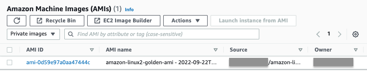
Amazon EC2 – You can now remove launch permissions for Amazon Machine Images (AMIs) that are directly shared with your AWS account.

X in Y – We launched existing AWS services and instance types in additional Regions:

For a full list of AWS announcements, be sure to keep an eye on the What’s New at AWS page.

Other AWS News
Here are some additional news items that you may find interesting:

AWS Open Source News and Updates – My colleague Ricardo Sueiras highlights new open source projects, tools, and demos from the AWS Community. Read Installment 134 to see what’s going on!

New Case Study – A new AWS case study describes how Taggle (a company focused on smart water solutions in Australia) created an IoT platform that runs on AWS and uses Amazon Kinesis Data Streams to store & ingest data in real time. Using AWS allowed them to scale to accommodate 80,000 additional sensors that will roll out in 2022.

Upcoming AWS Events
re:Invent 2022AWS re:Invent is just three weeks away! Join us live from November 28th to December 2nd for keynotes, training and certification opportunities, and over 1,500 technical sessions. If you cannot make it to Las Vegas you can also join us online to watch the keynotes and leadership sessions live. Be sure to check out the re:Invent 2022 Attendee Guides, each curated by an AWS Hero, AWS industry team, or AWS partner.

PeerTalk – If you will be attending re:Invent in person and are interested in meeting with me or any of our featured experts, be sure to check out PeerTalk, our new onsite networking program.

That’s all for this week!

Jeff;

This post is part of our Week in Review series. Check back each week for a quick roundup of interesting news and announcements from AWS.

How USAA built an Amazon S3 malware scanning solution

Post Syndicated from Jonathan Nguyen original https://aws.amazon.com/blogs/architecture/how-usaa-built-an-amazon-s3-malware-scanning-solution/

United Services Automobile Association (USAA) is a San Antonio-based insurance, financial services, banking, and FinTech company supporting millions of military members and their families. USAA has partnered with Amazon Web Services (AWS) to digitally transform and build multiple USAA solutions that help keep members safe and save members money and time.

Why build a S3 malware scanning solution?

As complex companies’ businesses continue to grow, there may be an increased need for collaboration and interactions with outside vendors. Prior to developing an Amazon Simple Storage Solution (Amazon S3) scanning solution, a security review and approval process for application teams to ingest data into an AWS Organization from external vendors’ AWS accounts may be warranted, to ensure additional threats are not being introduced. This could result in a lengthy review and exception process, and subsequently, could hinder the velocity of application teams’ collaboration with external vendors.

USAA security standards, like those of most companies, require all data from external vendors to be treated as untrusted, and therefore must be scanned by an antivirus or antimalware solution prior to being ingested by downstream processes within the AWS environment. Companies looking to automate the scanning process may want to consider a solution where all incoming external data flow through a demilitarized drop zone to be scanned, and subsequently released to downstream processes if malware and viruses are not detected.

S3 malware scanning solution overview

Dedicated AWS accounts should be provisioned for specific data classifications and used as a demilitarized zone (DMZ) for an untrusted staging area. The solution discussed in this blog uses a dedicated staging AWS account that controls the release of Amazon S3 objects to other AWS accounts within an AWS Organization. AWS accounts within an AWS Organization should follow security best practices in terms of infrastructure, networking, logging, and security. External vendors should explicitly be given limited permissions to appropriate resources in their respective staging S3 bucket.

A staging S3 bucket should have specific resource policies restricting which applications and identity and access management (IAM) principals can interact with S3 objects using object attributes, such as object tags, to determine whether an object has been scanned, and what the results of that scan are. Additional guardrails are implemented using Service Control Policies (SCP) to restrict authorized IAM principals to create or modify S3 object attributes (Figure 1).

Amazon S3 antivirus and antimalware scanning architecture workflow

Figure 1. Amazon S3 antivirus and antimalware scanning architecture workflow

  1. The external vendor copies an object to the staging S3 bucket.
  2. The staging S3 bucket has event notifications configured and generates an event.
  3. The S3 PutObject event is sent to an Object Created Amazon Simple Queue Service (Amazon SQS) queue topic.
  4. An Amazon Elastic Compute Cloud (Amazon EC2) Auto Scaling group is configured to scale based on messages in the Object Created SQS queue.
  5. An antivirus and antimalware scanning service application on the Amazon EC2 instances takes the following actions on objects within the Object Created Amazon SQS queue:
    a. Tag the S3 object with an “In Progress” status.
    b. Get the object from the Staging S3 bucket and stores it in a local ephemeral file system.
    c. Scan the copied object using antivirus or antimalware tool.
    d. Based on the antivirus or antimalware scan results, tag the S3 object with the scan results (for example, No_Malware_Detected vs. Malware_Detected).
    e. Create and publish a payload to the Object Scanned Amazon Simple Notification Service (Amazon SNS) topic, allowing application team filtering.
    f. Delete the message from the Object Created SQS queue.
  6. Application teams are subscribed to the Object Scanned SNS topic with a filter for their application.
  7. For any objects where a virus or malware is detected, a company can use its cyber threat response team to conduct a thorough analysis and take appropriate actions.

USAA built a custom anti-virus and anti-malware scanning application using EC2 instances, using a private, hardened Amazon Machine Image (AMI). For cost-efficacy purposes, the EC2 automatic scaling event can be configured based on Object Created SQS queue depth and Service Level Objective (SLO). A serverless version of an anti-virus and anti-malware solution can be used instead of an EC2 application, depending on your specific use-case and other factors. Some important factors include antivirus and antimalware tool serverless support, resource tuning and configuration requirements, and additional AWS services to manage that could possibly result in a bottleneck. If your enterprise is going with a serverless approach, you can use open-source tools such as ClamAV using Lambda functions.

In the event of an infected object, proper guardrails and response mechanisms need to be in place. USAA teams have developed playbooks to monitor the health and performance of S3 scanning solution, as well as responding to detected virus or malware.

This cloud native, event-driven solution has benefited multiple USAA application teams who have previously requested the ability to ingest data into AWS workloads from teams outside of USAA’s AWS Organization, and allowed additional capabilities and functionality to better serve their members. To enhance this solution even further, USAA’s security team plans to incorporate additional mechanisms to find specific objects that either failed or required additional processing, without having to scan all objects in the buckets. This can be accomplished by including an additional AWS Lambda function and Amazon DynamoDB table to track object metadata as objects get added to the Object Created SQS queue for processing. The metadata could possibly include information such as S3 bucket origin, S3 object key, version ID, scan status, and the original S3 event payload to replay the event into the Object Created SQS queue. The Lambda function primarily ensures the DynamoDB table is kept up to date as objects are processed, as well as handling issues for objects that may need to be reprocessed. The DynamoDB table also has time-to-live (TTL) configured to clear records as they expire from the Staging S3 bucket.

Conclusion

In this post, we reviewed how USAA’s Public Cloud Security team facilitated collaboration and interactions with external vendors and AWS workloads securely by creating a scalable solution to scan S3 objects for virus and malware prior to releasing objects downstream. The solution uses native AWS services and can be utilized for any use-cases requiring antivirus or antimalware capabilities. Because the S3 object scanning solution uses EC2 instances, you can use your existing antivirus or antimalware enterprise tool.

Adding approval notifications to EC2 Image Builder before sharing AMIs

Post Syndicated from Sheila Busser original https://aws.amazon.com/blogs/compute/adding-approval-notifications-to-ec2-image-builder-before-sharing-amis-2/

­­­­­This blog post is written by, Glenn Chia Jin Wee, Associate Cloud Architect, and Randall Han, Professional Services.

You may be required to manually validate the Amazon Machine Image (AMI) built from an Amazon Elastic Compute Cloud (Amazon EC2) Image Builder pipeline before sharing this AMI to other AWS accounts or to an AWS organization. Currently, Image Builder provides an end-to-end pipeline that automatically shares AMIs after they’ve been built.

In this post, we will walk through the steps to enable approval notifications before AMIs are shared with other AWS accounts. Image Builder supports automated image testing using test components. The recommended best practice is to automate test steps, however situations can arise where test steps become either challenging to automate or internal compliance policies mandate manual checks be conducted prior to distributing images. In such situations, having a manual approval step is useful if you would like to verify the AMI configuration before it is shared to other AWS accounts or an AWS Organization. A manual approval step reduces the potential for sharing an incorrectly configured AMI with other teams which can lead to downstream issues. This solution sends an email with a link to approve or reject the AMI. Users approve the AMI after they’ve verified that it is built according to specifications. Upon approving the AMI, the solution automatically shares it with the specified AWS accounts.

OverviewArchitecture Diagram

  1. In this solution, an Image Builder Pipeline is run that builds a Golden AMI in Account A. After the AMI is built, Image Builder publishes data about the AMI to an Amazon Simple Notification Service (Amazon SNS)
  2. The SNS Topic passes the data to an AWS Lambda function that subscribes to it.
  3. The Lambda function that subscribes to this topic retrieves the data, formats it, and then starts an SSM Automation, passing it the AMI Name and ID.
  4. The first step of the SSM Automation is a manual approval step. The SSM Automation first publishes to an SNS Topic that has an email subscription with the Approver’s email. The approver will receive the email with a URL that they can click to approve the step.
  5. The approval step defines a specific AWS Identity and Access Management (IAM) Role as an approver. This role has the minimum required permissions to approve the manual approval step. After performing manual tests on the Golden AMI, the Approver principal will assume this role.
  6. After assuming this role, the approver will click on the approval link that was sent via email. After approving the step, an AWS Lambda Function is triggered.
  7. This Lambda Function shares the Golden AMI with Account B and sends an email notifying the Target Account Recipients that the AMI has been shared.

Prerequisites

For this walkthrough, you will need the following:

  • Two AWS accounts – one to host the solution resources, and the second which receives the shared Golden AMI.
    • In the account that hosts the solution, prepare an AWS Identity and Access Management (IAM) principal with the sts:AssumeRole permission. This principal must assume the IAM Role that is listed as an approver in the Systems Manager approval step. The ARN of this IAM principal is used in the AWS CloudFormation Approver parameter, This ARN is added to the trust policy of approval IAM Role.
    • In addition, in the account hosting the solution, ensure that the IAM principal deploying the CloudFormation template has the required permissions to create the resources in the stack.
  • A new Amazon Virtual Private Cloud (Amazon VPC) will be created from the stack. Make sure that you have fewer than five VPCs in the selected Region.

Walkthrough

In this section, we will guide you through the steps required to deploy the Image Builder solution. The solution is deployed with CloudFormation.

In this scenario, we deploy the solution within the approver’s account. The approval email will be sent to a predefined email address for manual approval, before the newly created AMI is shared to target accounts.

The approver first assumes the approval IAM Role and then selects the approval link. This leads to the Systems Manager approval page. Upon approval, an email notification will be sent to the predefined target account email address, notifying the relevant stakeholders that the AMI has been successfully shared.

The high-level steps we will follow are:

  1. In Account A, deploy the provided AWS CloudFormation template. This includes an example Image Builder Pipeline, Amazon SNS topics, Lambda functions, and an SSM Automation Document.
  2. Approve the SNS subscription from your supplied email address.
  3. Run the pipeline from the Amazon EC2 Image Builder Console.
  4. [Optional] To conduct manual tests, launch an Amazon EC2 instance from the built AMI after the pipeline runs.
  5. An email will be sent to you with options to approve or reject the step. Ensure that you have assumed the IAM Role that is the approver before clicking the approval link that leads to the SSM console approval page.
  6. Upon approving the step, an AWS Lambda function shares the AMI to the Account B and also sends an email to the target account email recipients notifying them that the AMI has been shared.
  7. Log in to Account B and verify that the AMI has been shared.

Step 1: Deploy the AWS CloudFormation template

1. The CloudFormation template, template.yaml that deploys the solution can also found at this GitHub repository. Follow the instructions at the repository to deploy the stack.

Step 2: Verify your email address

  1. After running the deployment, you will receive an email prompting you to confirm the Subscription at the approver email address. Choose Confirm subscription.

SNS Topic Subscription confirmation email

  1. This leads to the following screen, which shows that your subscription is confirmed.

subscription-confirmation

  1. Repeat the previous 2 steps for the target email address.

Step 3: Run the pipeline from the Image Builder console

  1. In the Image Builder console, under Image pipelines, select the checkbox next to the Pipeline created, choose Actions, and select Run pipeline.

run-image-builder-pipeline

Note: The pipeline takes approximately 20 – 30 minutes to complete.

Step 4: [Optional] Launch an Amazon EC2 instance from the built AMI

If you have a requirement to manually validate the AMI before sharing it with other accounts or to the AWS organization an approver will launch an Amazon EC2 instance from the built AMI and conduct manual tests on the EC2 instance to make sure it is functional.

  1. In the Amazon EC2 console, under Images, choose AMIs. Validate that the AMI is created.

ami-in-account-a

  1. Follow AWS docs: Launching an EC2 instances from a custom AMI for steps on how to launch an Amazon EC2 instance from the AMI.

Step 5: Select the approval URL in the email sent

  1. When the pipeline is run successfully, you will receive another email with a URL to approve the AMI.

approval-email

  1. Before clicking on the Approve link, you must assume the IAM Role that is set as an approver for the Systems Manager step.
  2. In the CloudFormation console, choose the stack that was deployed.

cloudformation-stack

4. Choose Outputs and copy the IAM Role name.

ssm-approval-role-output

5. While logged in as the IAM Principal that has permissions to assume the approval IAM Role, follow the instructions at AWS IAM documentation for switching a role using the console to assume the approval role.
In the Switch Role page, in Role paste the name of the IAM Role that you copied in the previous step.

Note: This IAM Role was deployed with minimum permissions. Hence, seeing warning messages in the console is expected after assuming this role.

switch-role

6. Now in the approval email, select the Approve URL. This leads to the Systems Manager console. Choose Submit.

approve-console

7. After approving the manual step, the second step is executed, which shares the AMI to the target account.

automation-step-success

Step 6: Verify that the AMI is shared to Account B

  1. Log in to Account B.
  2. In the Amazon EC2 console, under Images, choose AMIs. Then, in the dropdown, choose Private images. Validate that the AMI is shared.

verify-ami-in-account-b

  1. Verify that a success email notification was sent to the target account email address provided.

target-email

Clean up

This section provides the necessary information for deleting various resources created as part of this post.

  1. Deregister the AMIs that were created and shared.
    1. Log in to Account A and follow the steps at AWS documentation: Deregister your Linux AMI.
  2. Delete the CloudFormation stack. For instructions, refer to Deleting a stack on the AWS CloudFormation console.

Conclusion

In this post, we explained how to enable approval notifications for an Image Builder pipeline before AMIs are shared to other accounts. This solution can be extended to share to more than one AWS account or even to an AWS organization. With this solution, you will be notified when new golden images are created, allowing you to verify the accuracy of their configuration before sharing them to for wider use. This reduces the possibility of sharing AMIs with misconfigurations that the written tests may not have identified.

We invite you to experiment with different AMIs created using Image Builder, and with different Image Builder components. Check out this GitHub repository for various examples that use Image Builder. Also check out this blog on Image builder integrations with EC2 Auto Scaling Instance Refresh. Let us know your questions and findings in the comments, and have fun!

ICYMI: Serverless Q3 2022

Post Syndicated from David Boyne original https://aws.amazon.com/blogs/compute/serverless-icymi-q3-2022/

Welcome to the 19th edition of the AWS Serverless ICYMI (in case you missed it) quarterly recap. Every quarter, we share all the most recent product launches, feature enhancements, blog posts, webinars, Twitch live streams, and other interesting things that you might have missed!

In case you missed our last ICYMI, check out what happened last quarter here.

AWS Lambda

AWS has now introduced tiered pricing for Lambda. With tiered pricing, customers who run large workloads on Lambda can automatically save on their monthly costs. Tiered pricing is based on compute duration measured in GB-seconds. The tiered pricing breaks down as follows:

With tiered pricing, you can save on the compute duration portion of your monthly Lambda bills. This allows you to architect, build, and run large-scale applications on Lambda and take advantage of these tiered prices automatically. To learn more about Lambda cost optimizations, watch the new serverless office hours video.

Developers are using AWS SAM CLI to simplify serverless development making it easier to build, test, package, and deploy their serverless applications.  For JavaScript and TypeScript developers, you can now simplify your Lambda development further using esbuild in the AWS SAM CLI.

Code example of esbuild with SAM

Together with esbuild and SAM Accelerate, you can rapidly iterate on your code changes in the AWS Cloud. You can approximate the same levels of productivity as when testing locally, while testing against a realistic application environment in the cloud. esbuild helps simplify Lambda development with support for tree shaking, minification, source maps, and loaders. To learn more about this feature, read the documentation.

Lambda announced support for Attribute-Based Access Control (ABAC). ABAC is designed to simplify permission management using access permissions based on tags. These can be attached to IAM resources, such as IAM users, and roles. ABAC support for Lambda functions allows you to scale your permissions as your organization innovates. It gives granular access to developers without requiring a policy update when a user or project is added, removed, or updated. To learn more about ABAC, read about ABAC for Lambda.

AWS Lambda Powertools is an open-source library to help customers discover and incorporate serverless best practices more easily. Powertools for TypeScript is now generally available and currently focused on three observability features: distributed tracing (Tracer), structured logging (Logger), and asynchronous business and application metrics (Metrics). Powertools is helping builders around the world with more than 10M downloads it is also available in Python and Java programming languages.

To learn more:

AWS Step Functions

Amazon States Language (ASL) provides a set of functions known as intrinsics that perform basic data transformations. Customers have asked for additional intrinsics to perform more data transformation tasks, such as formatting JSON strings, creating arrays, generating UUIDs, and encoding data. Step functions have now added 14 new intrinsic functions which can be grouped into six categories:

Intrinsic functions allow you to reduce the use of other services to perform basic data manipulations in your workflow. Read the release blog for use-cases and more details.

Step Functions expanded its AWS SDK integrations with support for Amazon Pinpoint API 2.0, AWS Billing Conductor,  Amazon GameSparks, and 195 more AWS API actions. This brings the total to 223 AWS Services and 10,000+ API Actions.

Amazon EventBridge

EventBridge released support for bidirectional event integrations with Salesforce, allowing customers to consume Salesforce events directly into their AWS accounts. Customers can also utilize API Destinations to send EventBridge events back to Salesforce, completing the bidirectional event integrations between Salesforce and AWS.

EventBridge also released the ability to start receiving events from GitHub, Stripe, and Twilio using quick starts. Customers can subscribe to events from these SaaS applications and receive them directly onto their EventBridge event bus for further processing. With Quick Starts, you can use AWS CloudFormation templates to create HTTP endpoints for your event bus that are configured with security best practices.

To learn more:

Amazon DynamoDB

DynamoDB now supports bulk imports from Amazon S3 into new DynamoDB tables. You can use bulk imports to help you migrate data from other systems, load test your applications, facilitate data sharing between tables and accounts, or simplify your disaster recovery and business continuity plans. Bulk imports support CSV, DynamoDB JSON, and Amazon Ion as input formats. You can get started with DynamoDB import via API calls or the AWS Management Console. To learn more, read the documentation or follow this guide.

DynamoDB now supports up to 100 actions per transaction. With Amazon DynamoDB transactions, you can group multiple actions together and submit them as a single all-or-nothing operation. The maximum number of actions in a single transaction has now increased from 25 to 100. The previous limit of 25 actions per transaction would sometimes require writing additional code to break transactions into multiple parts. Now with 100 actions per transaction, builders will encounter this limit much less frequently. To learn more about best practices for transactions, read the documentation.

Amazon SNS

SNS has introduced the public preview of message data protection to help customers discover and protect sensitive data in motion without writing custom code. With message data protection for SNS, you can scan messages in real time for PII/PHI data and receive audit reports containing scan results. You can also prevent applications from receiving sensitive data by blocking inbound messages to an SNS topic or outbound messages to an SNS subscription. These scans include people’s names, addresses, social security numbers, credit card numbers, and prescription drug codes.

To learn more:

EDA Day – London 2022

The Serverless DA team hosted the world’s first event-driven architecture (EDA) day in London on September 1. This brought together prominent figures in the event-driven architecture community, AWS, and customer speakers, and AWS product leadership from EventBridge and Step Functions.

EDA day covered 13 sessions, 3 workshops, and a Q&A panel. The conference was keynoted by Gregor Hohpe and speakers included Sheen Brisals and Sarah Hamilton from Lego, Toli Apostolidis from Cinch, David Boyne and Marcia Villalba from Serverless DA, and the AWS product team leadership for the panel. Customers could also interact with EDA experts at the Serverlesspresso bar and the Ask the Experts whiteboard.

Gregor Hohpe talking at EDA Day London 2022

Gregor Hohpe talking at EDA Day London 2022

Picture of the crowd at EDA day 2022 in London

Serverless snippets collection added to Serverless Land

Serverless Land is a website that is maintained by the Serverless Developer Advocate team to help you build with workshops, patterns, blogs, and videos. The team has extended Serverless Land and introduced the new AWS Serverless snippets collection. Builders can use serverless snippets to find and integrate tools, code examples, and Amazon CloudWatch Logs Insights queries to help with their development workflow.

Serverless Blog Posts

July

Jul 13 – Optimizing Node.js dependencies in AWS Lambda

Jul 15 – Simplifying serverless best practices with AWS Lambda Powertools for TypeScript

Jul 15 – Creating a serverless Apache Kafka publisher using AWS Lambda 

Jul 18 – Understanding AWS Lambda scaling and throughput

Jul 19 – Introducing Amazon CodeWhisperer in the AWS Lambda console (In preview)

Jul 19 – Scaling AWS Lambda permissions with Attribute-Based Access Control (ABAC)

Jul 25 – Migrating mainframe JCL jobs to serverless using AWS Step Functions

Jul 28 – Using AWS Lambda to run external transactions on Db2 for IBM i

August

Aug 1 – Using certificate-based authentication for iOS applications with Amazon SNS

Aug 4 – Introducing tiered pricing for AWS Lambda

Aug 5 – Securely retrieving secrets with AWS Lambda

Aug 8 – Estimating cost for Amazon SQS message processing using AWS Lambda

Aug 9 – Building AWS Lambda governance and guardrails

Aug 11 – Introducing the new AWS Serverless Snippets Collection

Aug 12 – Introducing bidirectional event integrations with Salesforce and Amazon EventBridge

Aug 17 – Using custom consumer group ID support for AWS Lambda event sources for MSK and self-managed Kafka

Aug 24 – Speeding up incremental changes with AWS SAM Accelerate and nested stacks

Aug 29 – Deploying AWS Lambda functions using AWS Controllers for Kubernetes (ACK)

Aug 30 – Building cost-effective AWS Step Functions workflows

September

Sep 05 – Introducing new intrinsic functions for AWS Step Functions

Sep 08 – Introducing message data protection for Amazon SNS

Sep 14 – Lifting and shifting a web application to AWS Serverless: Part 1

Sep 14 – Lifting and shifting a web application to AWS Serverless: Part 2

Videos

Serverless Office Hours – Tues 10AM PT

Weekly live virtual office hours. In each session we talk about a specific topic or technology related to serverless and open it up to helping you with your real serverless challenges and issues. Ask us anything you want about serverless technologies and applications.

YouTube: youtube.com/serverlessland
Twitch: twitch.tv/aws

July

Jul 5 – AWS SAM Accelerate GA + more!

Jul 12 – Infrastructure as actual code

Jul 19 – The AWS Step Functions Workflows Collection

Jul 26 – AWS Lambda Attribute-Based Access Control (ABAC)

August

Aug 2 – AWS Lambda Powertools for TypeScript/Node.js

Aug 9 – AWS CloudFormation Hooks

Aug 16 – Java on Lambda best-practices

Aug 30 – Alex de Brie: DynamoDB Misconceptions

September

Sep 06 – AWS Lambda Cost Optimization

Sep 13 – Amazon EventBridge Salesforce integration

Sep 20 – .NET on AWS Lambda best practices

FooBar Serverless YouTube channel

Marcia Villalba frequently publishes new videos on her popular serverless YouTube channel. You can view all of Marcia’s videos at https://www.youtube.com/c/FooBar_codes.

July

Jul 7 – Amazon Cognito – Add authentication and authorization to your web apps

Jul 14 – Add Amazon Cognito to an existing application – NodeJS-Express and React

Jul 21 – Introduction to Amazon CloudFront – Add CDN to your applications

Jul 28 – Add Amazon S3 storage and use a CDN in an existing application

August

Aug 04 – Testing serverless application locally – Demo with Node.js, Express, and React

Aug 11 – Building Amazon CloudWatch dashboards with AWS CDK

Aug 19 – Let’s code – Lift and Shift migration to Serverless of Node.js, Express, React and Mongo app

Aug 25 – Let’s code – Lift and Shift migration to Serverless, migrating Authentication and Authorization

Aug 29 – Deploying AWS Lambda functions using AWS Controllers for Kubernetes (ACK)

September

Sep 1 – Run Artillery in a Lambda function | Load test your serverless applications

Sep 8 – Let’s code – Lift and Shift migration to Serverless, migrating Storage with Amazon S3 and CloudFront

Sep 15 – What are Event-Driven Architectures? Why we care?

Sep 22 – Queues – Point to Point Messaging – Exploring Event-Driven Patterns

Still looking for more?

The Serverless landing page has more information. The Lambda resources page contains case studies, webinars, whitepapers, customer stories, reference architectures, and even more Getting Started tutorials.

You can also follow the Serverless Developer Advocacy team on Twitter to see the latest news, follow conversations, and interact with the team.

Sign Amazon SNS messages with SHA256 hashing for HTTP subscriptions

Post Syndicated from Daniel Caminhas original https://aws.amazon.com/blogs/security/sign-amazon-sns-messages-with-sha256-hashing-for-http-subscriptions/

Amazon Simple Notification Service (Amazon SNS) now supports message signatures based on Secure Hash Algorithm 256 (SHA256) hashing. Amazon SNS signs the messages that are delivered from your Amazon SNS topic so that subscribed HTTP endpoints can verify the authenticity of the messages. In this blog post, we will show you how to enable message signatures based on SHA256 for your Amazon SNS topics.

About message signing verification

To verify the authenticity of a message sent to your HTTP endpoint by Amazon SNS, you can verify the message signature. There are two cases where we recommend verifying the authenticity of the message. The first is when Amazon SNS sends a message to an HTTP endpoint that you subscribed to a topic. The second is when Amazon SNS sends a confirmation message to your HTTP endpoint after the Subscribe or the Unsubscribe API actions. For more information, see Verifying the signatures of Amazon SNS messages in the Amazon SNS Developer Guide.

Amazon SNS now supports two message signature versions:

  • Signature version 1 – Amazon SNS creates the signature based on the SHA1 hash of the message.
  • Signature version 2 – Amazon SNS creates the signature based on the SHA256 hash of the message.

Amazon SNS adds the SignatureVersion property to the JSON payload of messages delivered to HTTP endpoints, as shown in the following code snippet. For more information on the JSON payload format, see Parsing message formats in the Amazon SNS Developer Guide.

{
  "Type" : "Notification",
  "MessageId" : "22b80b92-fdea-4c2c-8f9d-bdfb0c7bf324",
  "TopicArn" : "arn:aws:sns:us-west-2:123456789012:MyTopic",
  "Subject" : "My First Message",
  "Message" : "Hello world!",
  "Timestamp" : "2022-08-02T00:54:06.655Z",
  "SignatureVersion" : "2",
  "Signature" : "EXAMPLEw6JRN...",
  "SigningCertURL" : "https://sns.us-west-2.amazonaws.com/SimpleNotificationService-f3ecfb7224c7233fe7bb5f59f96de52f.pem",
  "UnsubscribeURL" : "https://sns.us-west-2.amazonaws.com/?Action=Unsubscribe&SubscriptionArn=arn:aws:sns:us-west-2:123456789012:MyTopic:c9135db0-26c4-47ec-8998-413945fb5a96"
}

What to consider before you enable message signatures based on SHA256 for your Amazon SNS topic

As an Amazon SNS topic owner, before you enable SHA256 support for your topic, we recommend communicating with the owners of the HTTP endpoints that are subscribed to your topic. They might need to update their message signature verification logic to accommodate the new signature version. If the endpoint owners are using the AWS SDK feature for verifying the Amazon SNS message signatures, they need to make sure that they are using one of the following versions of the AWS SDK: Java 1.12.285, JavaScript 0.3.5, Ruby 1.54.0, PHP 1.8.0 or .NET 3.7.3.96.

How to enable message signatures based on SHA256 for your Amazon SNS topic

By default, Amazon SNS topics use SHA1 for hashing the message signature. You can enable SHA256 support for your topic by setting the topic attribute SignatureVersion to 2 using the AWS Software Development Kit (AWS SDK), or AWS Command Line Interface (AWS CLI).

The following code example shows how to set the topic attribute SignatureVersion by using the AWS CLI.

aws sns set-topic-attributes \
    --topic-arn arn:aws:sns:us-west-2:123456789012:MyTopic \
    --attribute-name SignatureVersion \
    --attribute-value 2

The following code example shows how to set the SignatureVersion attribute by using the AWS SDK for Java.

public static void enableSHA256Support(SnsClient snsClient, String topicArn) {

        try {

            SetTopicAttributesRequest request = SetTopicAttributesRequest.builder()
                .attributeName("SignatureVersion")
                .attributeValue("2")
                .topicArn(topicArn)
                .build();

            SetTopicAttributesResponse result = snsClient.setTopicAttributes(request);
            System.out.println("\n\nStatus was " + result.sdkHttpResponse().statusCode() + "\n\nTopic " + request.topicArn()
                + " updated " + request.attributeName() + " to " + request.attributeValue());

        } catch (SnsException e) {
            System.err.println(e.awsErrorDetails().errorMessage());
        }
    }

Conclusion

Amazon SNS topic owners can now enable message signatures based on SHA256 hashing. In this post, you learned how to choose the hashing algorithm, either SHA256 or SHA1, for your SNS topic. For more information, see Verifying the signatures of Amazon SNS messages in the Amazon SNS Developer Guide, and SetTopicAttributes in the Amazon SNS API Reference.

For more serverless learning resources, visit Serverless Land.

If you have feedback about this post, submit comments in the Comments section below. If you have questions about this post, contact AWS Support.

Want more AWS Security how-to content, news, and feature announcements? Follow us on Twitter.

Author

Daniel Caminhas

Daniel is a software development engineer for Amazon SNS.

Author

Ahmed Abouzeid

Ahmed is a software development manager for Amazon SNS.

Introducing message data protection for Amazon SNS

Post Syndicated from Julian Wood original https://aws.amazon.com/blogs/compute/introducing-message-data-protection-for-amazon-sns/

This post is written by Otavio Ferreira, Senior Software Development Manager, Marc Pinaud, Senior Product Manager, Usman Nisar, Senior Software Engineer, Hardik Vasa, Senior Solutions Architect, and Mithun Mallick, Senior Specialist Solution Architect.

Today, we are announcing the public preview release of new data protection capabilities for Amazon Simple Notification Service (SNS), message data protection. This is a new way to discover and protect sensitive data in motion at scale, without writing custom code.

SNS is a fully managed serverless messaging service. It provides topics for push-based, many-to-many pub/sub messaging for decoupling distributed systems, microservices, and event-driven serverless applications. As applications grow, so does the amount of data transmitted and the number of systems sending and receiving data. When moving data between different applications, guardrails can help you comply with data privacy regulations that require you to safeguard sensitive personally identifiable information (PII) or protected health information (PHI).

With message data protection for SNS, you can scan messages in real time for PII/PHI data and receive audit reports containing scan results. You can also prevent applications from receiving sensitive data by blocking inbound messages to an SNS topic or outbound messages to an SNS subscription. Message data protection for SNS supports a repository of over 25 unique PII/PHI data identifiers. These include people’s names, addresses, social security numbers, credit card numbers, and prescription drug codes.

These capabilities can help you adhere to a variety of compliance regulations, including HIPAA, FedRAMP, GDPR, and PCI. For more information, including the complete list of supported data identifiers, see message data protection in the SNS Developer Guide.

Overview

SNS topics enable you to integrate distributed applications more easily. As applications become more complex, it can become challenging for topic owners to manage the data flowing through their topics. Developers that publish messages to a topic may inadvertently send sensitive data, increasing regulatory risk. Message data protection enables SNS topic owners to protect sensitive application data with built-in, no-code, scalable capabilities.

To discover and protect data flowing through SNS topics with message data protection, topic owners associate data protection policies to their topics. Within these policies, you can write statements that define which types of sensitive data you want to discover and protect. As part of this, you can define whether you want to act on data flowing inbound to a topic or outbound to a subscription, which AWS accounts or specific AWS Identity and Access Management (AWS IAM) principals the policy is applicable to, and the actions you want to take on the data.

Message data protection provides two actions to help you protect your data. Auditing, to report on the amount of PII/PHI found, and blocking, to prevent the publishing or delivery of payloads that contain PII/PHI data. Once the data protection policy is set, message data protection uses pattern matching and machine learning models to scan your messages in real time for PII/PHI data identifiers and enforce the data protection policy.

For auditing, you can choose to send audit reports to Amazon Simple Storage Service (S3) for archival, Amazon Kinesis Data Firehose for analytics, or Amazon CloudWatch for logging and alarming. Message data protection does not interfere with the topic owner’s ability to use message data encryption at rest, nor with the subscriber’s ability to filter out unwanted messages using message filtering.

Applying message data protection in a use case

Consider an application that processes a variety of transactions for a set of health clinics, an organization that operates in a regulated environment. Compliance frameworks require that the organization take measures to protect both sensitive health records and financial information.

Reference architecture

The application is based on an event-driven serverless architecture. It has a data protection policy attached to the topic to audit for sensitive data and prevent downstream systems from processing certain data types.

The application publishes an event to an SNS topic every time a patient schedules a visit or sees a doctor at a clinic. The SNS topic fans out the event to two subscribed systems, billing and scheduling. Each system stores events in an Amazon SQS queue, which is processed using an AWS Lambda function.

Setting a data protection policy to an SNS topic

You can apply a data protection policy to an SNS topic using the AWS Management Console, the AWS CLI, or the AWS SDKs. You can also use AWS CloudFormation to automate the provisioning of the data protection policy.

This example uses CloudFormation to provision the infrastructure. You have two options for deploying the resources:

  • Deploy the resources by using the message data protection deploy script within the aws-sns-samples repository in GitHub.
  • Alternatively, use the following four CloudFormation templates in order. Allow time for each stack to complete before deploying the next stack, to create the following resources:

1. Prerequisites template

  • Two IAM roles with a managed policy that allows access to receive messages from the SNS topic, one for the billing and another for scheduling system, respectively.

2. Topic owner template

  • SNS topic that delivers events to two distinct systems.
  • A data protection policy that defines both auditing and blocking actions for specific types of PII and PHI.
  • S3 bucket to archive audit findings.
  • CloudWatch log group to monitor audit findings.
  • Kinesis Data Firehose to deliver audit findings to other destinations.

3. Scheduling subscriber template

  • SQS queue for the Scheduling system.
  • Lambda function for the Scheduling system.

4. Billing subscriber template

  • SQS queue for the Billing system.
  • Lambda function for the Billing system.

CloudFormation creates the following data protection policy as part of the topic owner template:

  ClinicSNSTopic:
    Type: 'AWS::SNS::Topic'
    Properties:
      TopicName: SampleClinic
      DataProtectionPolicy:
        Name: data-protection-example-policy
        Description: Policy Description
        Version: 2021-06-01
        Statement:
          - Sid: audit
            DataDirection: Inbound
            Principal:
             - '*'
            DataIdentifier:
              - 'arn:aws:dataprotection::aws:data-identifier/Address'
              - 'arn:aws:dataprotection::aws:data-identifier/AwsSecretKey'
              - 'arn:aws:dataprotection::aws:data-identifier/DriversLicense-US'
              - 'arn:aws:dataprotection::aws:data-identifier/EmailAddress'
              - 'arn:aws:dataprotection::aws:data-identifier/IpAddress'
              - 'arn:aws:dataprotection::aws:data-identifier/NationalDrugCode-US'
              - 'arn:aws:dataprotection::aws:data-identifier/PassportNumber-US'
              - 'arn:aws:dataprotection::aws:data-identifier/Ssn-US'
            Operation:
              Audit:
                SampleRate: 99
                FindingsDestination:
                  CloudWatchLogs:
                    LogGroup: !Ref AuditCWLLogs
                  Firehose:
                    DeliveryStream: !Ref AuditFirehose
                NoFindingsDestination:
                  S3:
                    Bucket: !Ref AuditS3Bucket
          - Sid: deny-inbound
            DataDirection: Inbound
            Principal:
              - '*'
            DataIdentifier:
              - 'arn:aws:dataprotection::aws:data-identifier/PassportNumber-US'
              - 'arn:aws:dataprotection::aws:data-identifier/Ssn-US'
            Operation:
              Deny: {}
          - Sid: deny-outbound-billing
            DataDirection: Outbound
            Principal:
              - !ImportValue "BillingRoleExportDataProtectionDemo"
            DataIdentifier:
              - 'arn:aws:dataprotection::aws:data-identifier/NationalDrugCode-US'
            Operation:
              Deny: {}
          - Sid: deny-outbound-scheduling
            DataDirection: Outbound
            Principal:
              - !ImportValue "SchedulingRoleExportDataProtectionDemo"
            DataIdentifier:
              - 'arn:aws:dataprotection::aws:data-identifier/Address'
              - 'arn:aws:dataprotection::aws:data-identifier/CreditCardNumber'
            Operation:
              Deny: {}

This data protection policy defines:

  • Metadata about the data protection policy, for example name, description, version, and statement IDs (sid).
  • The first statement (sid: audit) scans inbound messages from all principals for addresses, social security numbers, driver’s license, email addresses, IP addresses, national drug codes, passport numbers, and AWS secret keys.
    • The sampling rate is set to 99% so almost all messages are scanned for the defined PII/PHI.
    • Audit results with findings are delivered to CloudWatch Logs and Kinesis Data Firehose for analytics. Audit results without findings are archived to S3.
  • The second statement (sid: deny-inbound) blocks inbound messages to the topic coming from any principal, if the payload includes either a social security number or passport number.
  • The third statement (sid: deny-outbound-billing) blocks the delivery of messages to subscriptions created by the BillingRole, if the messages include any national drug codes.
  • The fourth statement (sid: deny-outbound-scheduling) blocks the delivery of messages to subscriptions created by the SchedulingRole, if the messages include any credit card numbers or addresses.

Testing the capabilities

Test the message data protection capabilities using the following steps:

  1. Publish a message without PII/PHI data to the Clinic Topic. In the CloudWatch console, navigate to the log streams of the respective Lambda functions to confirm that the message is delivered to both subscribers. Both messages are delivered because the payload contains no sensitive data for the data protection policy to deny. The log message looks as follows:
    "This is a demo! received from queue arn:aws:sqs:us-east-1:111222333444:Scheduling-SchedulingQueue"
  2. Publish a message with a social security number (try ‘SSN: 123-12-1234’) to the Clinic Topic. The request is denied, and an audit log is delivered to your CloudWatch Logs log group and Firehose delivery stream.
  3. Navigate to the CloudWatch log console and confirm that the audit log is visible in the /aws/vendedlogs/clinicaudit CloudWatch log group. The following example shows that the data protection policy (sid: deny-inbound) denied the inbound message as the payload contains a US social security number (SSN) between the 5th and the 15th character.
    {
        "messageId": "77ec5f0c-5129-5429-b01d-0457b965c0ac",
        "auditTimestamp": "2022-07-28T01:27:40Z",
        "callerPrincipal": "arn:aws:iam::111222333444:role/Admin",
        "resourceArn": "arn:aws:sns:us-east-1:111222333444:SampleClinic",
        "dataIdentifiers": [
            {
                "name": "Ssn-US",
                "count": 1,
                "detections": [
                    {
                        "start": 5,
                        "end": 15
                    }
                ]
            }
        ]
    }
    
  4. You can use the CloudWatch metrics, MessageWithFindings and MessageWithNoFindings, to track how frequently PII/PHI data is published to an SNS topic. Here’s an example of what the CloudWatch metric graph looks like as the amount of sensitive data published to a topic varies over time:
    CloudWatch metric graph
  5. Publish a message with an address (try ‘410 Terry Ave N, Seattle 98109, WA’). The request is only delivered to the Billing subscription. The data protection policy (sid: deny-outbound-scheduling) denies the outbound message to the Scheduling subscription as the payload contains an address.
  6. Confirm that the message is only delivered to the Billing Lambda function by navigating to the CloudWatch console and inspecting the logs of the two respective Lambda functions. The CloudWatch log of the Billing Lambda function contains the sensitive message that was delivered to it as it was an authorized subscriber. Here’s an example of what the log contains:410 Terry Ave N, Seattle 98109, WA received from queue arn:aws:sqs:us-east-1:111222333444:Billing-BillingQueue
  7. Publish a message with a drug code (try ‘NDC: 0777-3105-02’). The request is only delivered to the Scheduling subscription. The data protection policy (sid: deny-outbound-billing) denies the outbound message to the Billing subscription as the payload contains a drug code.
  8. Confirm that the message is only delivered to the Scheduling Lambda function by navigating to the CloudWatch console and inspecting the logs of the two respective Lambda functions. The CloudWatch log of the Scheduling Lambda function contains the sensitive message that was delivered to it as it was an authorized subscriber. Here’s an example of what the log contains:
    NDC: 0777-3105-02 received from queue arn:aws:sqs:us-east-1:111222333444:Scheduling-SchedulingQueue

Cleaning up

After testing, avoid incurring usage charges by deleting the resources that you created. Navigate to the CloudFormation console and delete the four CloudFormation stacks that you created during the walkthrough. Remember, you must delete all the objects from the S3 bucket before deleting the stack.

Conclusion

This post shows how message data protection enables a topic owner to discover and protect sensitive data that is exchanged through SNS topics. The example shows how to create a data protection policy that generates audit reports for sensitive data and blocks messages from delivery to specific subscribers if the payload contains sensitive data.

Get started with SNS and message data protection by using the AWS Management Console, AWS Command Line Interface (CLI), AWS SDKs, or CloudFormation.

For more details, see message data protection in the SNS Developer Guide. For information on pricing, see SNS pricing.

For more serverless learning resources, visit Serverless Land.

Coordinating large messages across accounts and Regions with Amazon SNS and SQS

Post Syndicated from Mrudhula Balasubramanyan original https://aws.amazon.com/blogs/architecture/coordinating-large-messages-across-accounts-and-regions-with-amazon-sns-and-sqs/

Many organizations have applications distributed across various business units. Teams in these business units may develop their applications independent of each other to serve their individual business needs. Applications can reside in a single Amazon Web Services (AWS) account or be distributed across multiple accounts. Applications may be deployed to a single AWS Region or span multiple Regions.

Irrespective of how the applications are owned and operated, these applications need to communicate with each other. Within an organization, applications tend to be part of a larger system, therefore, communication and coordination among these individual applications is critical to overall operation.

There are a number of ways to enable coordination among component applications. It can be done either synchronously or asynchronously:

  • Synchronous communication uses a traditional request-response model, in which the applications exchange information in a tightly coupled fashion, introducing multiple points of potential failure.
  • Asynchronous communication uses an event-driven model, in which the applications exchange messages as events or state changes and are loosely coupled. Loose coupling allows applications to evolve independently of each other, increasing scalability and fault-tolerance in the overall system.

Event-driven architectures use a publisher-subscriber model, in which events are emitted by the publisher and consumed by one or more subscribers.

A key consideration when implementing an event-driven architecture is the size of the messages or events that are exchanged. How can you implement an event-driven architecture for large messages, beyond the default maximum of the services? How can you architect messaging and automation of applications across AWS accounts and Regions?

This blog presents architectures for enhancing event-driven models to exchange large messages. These architectures depict how to coordinate applications across AWS accounts and Regions.

Challenge with application coordination

A challenge with application coordination is exchanging large messages. For the purposes of this post, a large message is defined as an event payload between 256 KB and 2 GB. This stems from the fact that Amazon Simple Notification Service (Amazon SNS) and Amazon Simple Queue Service (Amazon SQS) currently have a maximum event payload size of 256 KB. To exchange messages larger than 256 KB, an intermediate data store must be used.

To exchange messages across AWS accounts and Regions, set up the publisher access policy to allow subscriber applications in other accounts and Regions. In the case of large messages, also set up a central data repository and provide access to subscribers.

Figure 1 depicts a basic schematic of applications distributed across accounts communicating asynchronously as part of a larger enterprise application.

Asynchronous communication across applications

Figure 1. Asynchronous communication across applications

Architecture overview

The overview covers two scenarios:

  1. Coordination of applications distributed across AWS accounts and deployed in the same Region
  2. Coordination of applications distributed across AWS accounts and deployed to different Regions

Coordination across accounts and single AWS Region

Figure 2 represents an event-driven architecture, in which applications are distributed across AWS Accounts A, B, and C. The applications are all deployed to the same AWS Region, us-east-1. A single Region simplifies the architecture, so you can focus on application coordination across AWS accounts.

Application coordination across accounts and single AWS Region

Figure 2. Application coordination across accounts and single AWS Region

The application in Account A (Application A) is implemented as an AWS Lambda function. This application communicates with the applications in Accounts B and C. The application in Account B is launched with AWS Step Functions (Application B), and the application in Account C runs on Amazon Elastic Container Service (Application C).

In this scenario, Applications B and C need information from upstream Application A. Application A publishes this information as an event, and Applications B and C subscribe to an SNS topic to receive the events. However, since they are in other accounts, you must define an access policy to control who can access the SNS topic. You can use sample Amazon SNS access policies to craft your own.

If the event payload is in the 256 KB to 2 GB range, you can use Amazon Simple Storage Service (Amazon S3) as the intermediate data store for your payload. Application A uses the Amazon SNS Extended Client Library for Java to upload the payload to an S3 bucket and publish a message to an SNS topic, with a reference to the stored S3 object. The message containing the metadata must be within the SNS maximum message limit of 256 KB. Amazon EventBridge is used for routing events and handling authentication.

The subscriber Applications B and C need to de-reference and retrieve the payloads from Amazon S3. The SQS queue in Account B and Lambda function in Account C subscribe to the SNS topic in Account A. In Account B, a Lambda function is used to poll the SQS queue and read the message with the metadata. The Lambda function uses the Amazon SQS Extended Client Library for Java to retrieve the S3 object referenced in the message.

The Lambda function in Account C uses the Payload Offloading Java Common Library for AWS to get the referenced S3 object.

Once the S3 object is retrieved, the Lambda functions in Accounts B and C process the data and pass on the information to downstream applications.

This architecture uses Amazon SQS and Lambda as subscribers because they provide libraries that support offloading large payloads to Amazon S3. However, you can use any Java-enabled endpoint, such as an HTTPS endpoint that uses Payload Offloading Java Common Library for AWS to de-reference the message content.

Coordination across accounts and multiple AWS Regions

Sometimes applications are spread across AWS Regions, leading to increased latency in coordination. For existing applications, it could take substantive effort to consolidate to a single Region. Hence, asynchronous coordination would be a good fit for this scenario. Figure 3 expands on the architecture presented earlier to include multiple AWS Regions.

Application coordination across accounts and multiple AWS Regions

Figure 3. Application coordination across accounts and multiple AWS Regions

The Lambda function in Account C is in the same Region as the upstream application in Account A, but the Lambda function in Account B is in a different Region. These functions must retrieve the payload from the S3 bucket in Account A.

To provide access, configure the AWS Lambda execution role with the appropriate permissions. Make sure that the S3 bucket policy allows access to the Lambda functions from Accounts B and C.

Considerations

For variable message sizes, you can specify if payloads are always stored in Amazon S3 regardless of their size, which can help simplify the design.

If the application that publishes/subscribes large messages is implemented using the AWS Java SDK, it must be Java 8 or higher. Service-specific client libraries are also available in Python, C#, and Node.js.

An Amazon S3 Multi-Region Access Point can be an alternative to a centralized bucket for the payloads. It has not been explored in this post due to the asynchronous nature of cross-region replication.

In general, retrieval of data across Regions is slower than in the same Region. For faster retrieval, workloads should be run in the same AWS Region.

Conclusion

This post demonstrates how to use event-driven architectures for coordinating applications that need to exchange large messages across AWS accounts and Regions. The messaging and automation are enabled by the Payload Offloading Java Common Library for AWS and use Amazon S3 as the intermediate data store. These components can simplify the solution implementation and improve scalability, fault-tolerance, and performance of your applications.

Ready to get started? Explore SQS Large Message Handling.

Updated requirements for US toll-free phone numbers

Post Syndicated from Brent Meyer original https://aws.amazon.com/blogs/messaging-and-targeting/updated-requirements-for-us-toll-free-phone-numbers/

Many Amazon Pinpoint customers use toll-free phone numbers to send messages to their customers in the United States. A toll-free number is a 10-digit number that begins with one of the following three-digit codes: 800, 888, 877, 866, 855, 844, or 833. You can use toll-free numbers to send both SMS and voice messages to recipients in the US.

What’s changing

Historically, US toll-free numbers have been available to purchase with no registration required. To prevent spam and other types of abuse, the United States mobile carriers now require new toll-free numbers to be registered as well. The carriers also require all existing toll-free numbers to be registered by September 30, 2022. The carriers will block SMS messages sent from unregistered toll-free numbers after this date.

If you currently use toll-free numbers to send SMS messages, you must complete this registration process for both new and existing toll-free numbers. We’re committed to helping you comply with these changing carrier requirements.

Information you provide as part of this registration process will be provided to the US carriers through our downstream partners. It can take up to 15 business days for your registration to be processed. To help prevent disruptions of service with your toll-free number, you should submit your registration no later than September 12th, 2022.

Requesting new toll-free numbers

Starting today, when you request a United States toll-free number in the Amazon Pinpoint console, you’ll see a new page that you can use to register your use case. Your toll-free number registration must be completed and verified before you can use it to send SMS messages. For more information about completing this registration process, see US toll-free number registration requirements and process in the Amazon Pinpoint User Guide.

Registering existing toll-free numbers

You can also use the Amazon Pinpoint console to register toll-free numbers that you already have in your account. For more information about completing the registration process for existing toll-free numbers, see US toll-free number registration requirements and process in the Amazon Pinpoint User Guide.

In closing

Change is a constant factor in the SMS and voice messaging industry. Carriers often introduce new processes in order to protect their customers. The new registration requirements for toll-free numbers are a good example of these kinds of changes. We’ll work with you to help make sure that these changes have minimal impact on your business. If you have any concerns about these changing requirements, open a ticket in the AWS Support Center.

Using certificate-based authentication for iOS applications with Amazon SNS

Post Syndicated from Sam Dengler original https://aws.amazon.com/blogs/compute/using-certificate-based-authentication-for-ios-applications-with-amazon-sns/

This blog post is written by Yashlin Naidoo, Arnav Thakur, Kim Read, Guilherme Silva.

Amazon SNS enables you to send notifications to a mobile push endpoint using a platform application endpoint by dispatching the notification on your application’s behalf. Push notifications for iOS apps are sent using Apple Push Notification Service (APNs).

To send push notifications using SNS for APNS certificate-based authentication, you must provide a set of credentials for connecting to the Apple Push Notification Service (see prerequisites for push). SNS supports using certificate-based authentication (.p12), in addition to the new token-based authentication (.p8).

Certificate-based authentication uses a provider certificate to establish a secure connection between your provider and APNs. These certificates are tied to a single application and are used to send notifications to this application. This approach can be useful when you haven’t migrated to the new token-based authentication.

For new applications, we recommend using token-based authentication as it provides improved security. It removes the need for yearly renewal of the certificates and can also be shared amongst multiple applications. To learn about how to use token-based authentication, visit Token-Based authentication for iOS applications with Amazon SNS in the AWS Compute Blog.

This blog shows step-by-step instructions on how to build an iOS application. You learn how to create a new certificate from your Apple developer account, and set up a platform application and endpoint in the SNS console. Next, you will learn how to test your application by sending a push notification via SNS to your device. Finally, you view the push notification delivered to your device.

Setting up your iOS application

This section will go over:

  • Creating an iOS application.
  • Creating a .p12 certificate to upload to SNS.

Prerequisites:

Creating an iOS application

  1. Create a new XCode project. Select iOS as the platform.

    New XCode project

    New XCode project

  2. Select your Apple Developer Account team and organization identifier.

    Select your Apple Developer Account team

    Select your Apple Developer Account team

  3. In your project, go to Signing & Capabilities. Under signing, ensure that “Automatically manage signing” is checked and your team is selected.

    Signing & Capabilities

    Signing & Capabilities

  4. To add the push notification capability to your application, select “+” and select Push Notifications.
    Add push notification capability

    Add push notification capability

    This step creates resources on your Apple Developer Account (the App ID and adds Push notification capability to it). You can also verify this in your Apple Developer Account.

  5. Add the following code to AppDelegate.swift:
        import UIKit
        import UserNotifications
    
        @main
        class AppDelegate: UIResponder, UIApplicationDelegate {
    
        func application(_ application: UIApplication, didFinishLaunchingWithOptions launchOptions: [UIApplication.LaunchOptionsKey: Any]?) -> Bool {
        // Override point for customization after application launch
    
        //Call to register for push notifications when launched
        registerForPushNotifications()
    
        return true
        }
    
        // MARK: UISceneSession Lifecycle
    
        func application(_ application: UIApplication, configurationForConnecting connectingSceneSession: UISceneSession, options: UIScene.ConnectionOptions) -> UISceneConfiguration {
        // Called when a new scene session is being created.
        // Use this method to select a configuration to create the new scene with.
        return UISceneConfiguration(name: "Default Configuration", sessionRole: connectingSceneSession.role)
        }
    
        func application(_ application: UIApplication, didDiscardSceneSessions sceneSessions: Set<UISceneSession>) {
        // Called when the user discards a scene session.
        // If any sessions were discarded while the application was not running, this will be called shortly after application:didFinishLaunchingWithOptions.
        // Use this method to release any resources that were specific to the discarded scenes, as they will not return.
        }
    
        func getNotificationSettings() {
        UNUserNotificationCenter.current().getNotificationSettings { settings in
        print("Notification settings: \(settings)")
    
        guard settings.authorizationStatus == .authorized else { return }
        DispatchQueue.main.async {
        UIApplication.shared.registerForRemoteNotifications()
        }
    
        }
        }
    
        func registerForPushNotifications() {
        //1 this handles all notification-related activities in the app including push notifications
        UNUserNotificationCenter.current()
    
        //2 this requests authorization to send the types of notifications specifies in the options
        .requestAuthorization(
        options: [.alert, .sound, .badge]) { [weak self] granted, _ in
        print("Permission granted: \(granted)")
        guard granted else { return }
        self?.getNotificationSettings()
        }
    
        }
    
        func application(
        _ application: UIApplication,
        didRegisterForRemoteNotificationsWithDeviceToken deviceToken: Data
        ) {
        let tokenParts = deviceToken.map { data in String(format: "%02.2hhx", data) }
        let token = tokenParts.joined()
        print("Device Token: \(token)")
        }
    
        func application(
        _ application: UIApplication,
        didFailToRegisterForRemoteNotificationsWithError error: Error
        ) {
        print("Failed to register: \(error)")
        }
    
        }
  6. Build and run the application on an iPhone. Note that the push notification feature does not work with a simulator.
  7. On your phone, select “Allow” when prompted to allow push notifications.

    Allow push notifications

    Allow push notifications

  8. The debugger prints “Permission granted: true” if successful and returns the Device Token.

    Device token

    Device token

You have now configured an iOS application that can receive push notifications. Next, use the application to test sending push notifications with SNS using certificate-based authentication.

Creating a .p12 certificate to upload to SNS

After completing the previous step, you need:

  • An app identifier
  • A certificate signing request (CSR)
  • An SSL certificate

Create an identifier

  1. Log in to your Apple Developer Account.
  2. Choose Certificates, Identifiers & Profiles.
  3. In the Identifiers section, choose the Add button (+).
  4. In the Register a new identifier section, choose App IDs and select Continue.
  5. In the Select a type section, choose App, and select Continue.
  6. For Description, type the application description.
  7. For Bundle ID, use the Bundle ID assigned to your application. You can find this ID under Signing & Capabilities of your application in XCode (see step 3 under “Creating an application”).
  8. Under Capabilities, choose Push Notifications.
  9. Select Continue. In the Confirm your App ID panel, check that all values were entered correctly. The identifier should match your app ID and bundle ID.
  10. Select Register to register the new app ID.

Create a certificate signing request (CSR)

  1. Open Keychain Access located in /Applications/Utilities or search for it on Finder.
  2. Once opened, choose the tab Keychain Access Tab (next to the Apple icon). Navigate to Certificate Assistant and choose Request a Certificate from a Certificate Authority.
  3. Enter the Username, Email Address, Common Name and leave CA Email Address empty.
  4. Choose Saved to disk and choose Continue.

Create a certificate

  1. Log in to your Apple Developer Account.
  2. Choose Certificates, Identifiers & Profiles.
  3. In the Certificate section, select Create new certificate.
  4. Under services, choose your certificate: Apple Push Notification service SSL (Sandbox)/Apple Push Notification service SSL (Sandbox & Production).
  5. Keep Platform as iOS and choose App ID (Identifier) created previously.
  6. Upload the Certificate Signing Request created in the previous step and Download your certificate.

Create .p12 certificate to upload to SNS

  1. Once your certificate.cer file is downloaded (for example, “aps_development.cer”), open it to show in keychain access. Find Apple Development iOS Push Services: (Your Identifier Name/App ID Name) and ensure that the file is placed in the “Login” folder.
  2. Right-click and choose Export as file format .p12 and choose Save. Optionally, set a password.

Creating a new platform application using APNs certificate-based authentication

Prerequisites

To implement APNs certificate-based authentication from SNS, you must have:

  • An Apple Developer Account
  • An iOS mobile application

For creating a new SNS Platform Application that is used to store Push Notification Platform credentials, configurations and related configurations:

  1. Navigate to the SNS Console. Expand the Mobile menu and choose Create platform application.
  2. For the Application name field, enter an application name such as “myfirstiOSapp”. For Push Notification Platform, select Apple iOS/ VoIP/ macOS.

    Create platform application

    Create platform application

  3. Under the Apple Credentials section:
    1. If your application is in development, select the radio button for Used for development in sandbox. If your application is in production, uncheck Used for development in sandbox.
    2. For Push service, choose iOS and for Authentication method, choose Certificate.
    3. Under Certificate, select Choose file to upload the .p12 certificate file.
    4. If you configured a password while creating the certificate, enter this in the Certificate Password field.
    5. Choose Load Credentials from File to extract the Certificate and private key components.
  4. Event Notifications, Delivery Status Logging – Optional: Refer to the guide for enabling Delivery Status logs and the guide to set up Mobile Event related Notifications. More on this step can also be found in the best practices guide.

    Enter Apple credentials

    Enter Apple credentials

  5. Choose Create Platform Application. This creates a certificate-based authentication APNs Platform Application for iOS.

    Create platform application

    Create platform application

Creating a new platform endpoint using APNs token-based authentication

To send Push Notifications using SNS, a platform endpoint resource is created to store the destination address of the corresponding iOS application that is associated with the SNS platform application.

A destination address of a user’s device with the iOS application installed is identified by an unique device token. It is obtained once the app has registered successfully with APNs to receive push notifications. The details of the device token captured in the Platform Endpoint resource along with the configurations in the SNS Platform application are used in conjunction by the service to deliver a push notification message.

In the following steps, you create a new platform endpoint for a destination device that has the iOS application installed and is capable of receiving push notifications.

  1. Open your Platform Application. Choose Create Application Endpoint.

    Application endpoints list

    Application endpoints list

  2. Locate the Device token in the application logs of the iOS app provisioned earlier. Enter it in the Device Token Field.
  3. To store any additional arbitrary data for the endpoint, you can include in the User data field and choose Create application endpoint.

    Create application endpoint

    Create application endpoint

  4. Choose Create application endpoint and the details are shown on the console.

    Application endpoint detail

    Application endpoint detail

Testing a push notification from your device

In this section, you test sending a push notification to your device.

  1. From the SNS console, navigate to your platform endpoint and choose Publish message.
  2. Enter a message to send. This example uses a custom payload that allows you to provide additional APNs headers.

    Publish message

    Publish message

  3. Choose Publish message.
  4. The push notification is delivered to your device.

    Notification

    Notification

Conclusion

Developers send mobile push notifications for APNs certificate-based authentication by using a .p12 certificate to authenticate an Apple device endpoint. Certificate-based authentication ensures a secure connection through TLS (Transport Layer Security). The provider (SNS) initiates the request to APNs and validation from the provider and APNS is required to complete the secure connection.

Certificates expire annually and must be renewed to ensure that SNS can continue to deliver to the endpoint. In this post, you learn how to create an iOS application for APNs certificate-based authentication and integrate it with SNS to send push notifications to your device using a .p12 certificate to authenticate your application with the mobile endpoint.

To learn more about APNs certificate-based authentication with Amazon SNS, visit the Amazon SNS Developer Guide.

For more serverless learning resources, visit Serverless Land.

Introducing Amazon CodeWhisperer in the AWS Lambda console (In preview)

Post Syndicated from Julian Wood original https://aws.amazon.com/blogs/compute/introducing-amazon-codewhisperer-in-the-aws-lambda-console-in-preview/

This blog post is written by Mark Richman, Senior Solutions Architect.

Today, AWS is launching a new capability to integrate the Amazon CodeWhisperer experience with the AWS Lambda console code editor.

Amazon CodeWhisperer is a machine learning (ML)–powered service that helps improve developer productivity. It generates code recommendations based on their code comments written in natural language and code.

CodeWhisperer is available as part of the AWS toolkit extensions for major IDEs, including JetBrains, Visual Studio Code, and AWS Cloud9, currently supporting Python, Java, and JavaScript. In the Lambda console, CodeWhisperer is available as a native code suggestion feature, which is the focus of this blog post.

CodeWhisperer is currently available in preview with a waitlist. This blog post explains how to request access to and activate CodeWhisperer for the Lambda console. Once activated, CodeWhisperer can make code recommendations on-demand in the Lambda code editor as you develop your function. During the preview period, developers can use CodeWhisperer at no cost.

Amazon CodeWhisperer

Amazon CodeWhisperer

Lambda is a serverless compute service that runs your code in response to events and automatically manages the underlying compute resources for you. You can trigger Lambda from over 200 AWS services and software as a service (SaaS) applications and only pay for what you use.

With Lambda, you can build your functions directly in the AWS Management Console and take advantage of CodeWhisperer integration. CodeWhisperer in the Lambda console currently supports functions using the Python and Node.js runtimes.

When writing AWS Lambda functions in the console, CodeWhisperer analyzes the code and comments, determines which cloud services and public libraries are best suited for the specified task, and recommends a code snippet directly in the source code editor. The code recommendations provided by CodeWhisperer are based on ML models trained on a variety of data sources, including Amazon and open source code. Developers can accept the recommendation or simply continue to write their own code.

Requesting CodeWhisperer access

CodeWhisperer integration with Lambda is currently available as a preview only in the N. Virginia (us-east-1) Region. To use CodeWhisperer in the Lambda console, you must first sign up to access the service in preview here or request access directly from within the Lambda console.

In the AWS Lambda console, under the Code tab, in the Code source editor, select the Tools menu, and Request Amazon CodeWhisperer Access.

Request CodeWhisperer access in Lambda console

Request CodeWhisperer access in Lambda console

You may also request access from the Preferences pane.

Request CodeWhisperer access in Lambda console preference pane

Request CodeWhisperer access in Lambda console preference pane

Selecting either of these options opens the sign-up form.

CodeWhisperer sign up form

CodeWhisperer sign up form

Enter your contact information, including your AWS account ID. This is required to enable the AWS Lambda console integration. You will receive a welcome email from the CodeWhisperer team upon once they approve your request.

Activating Amazon CodeWhisperer in the Lambda console

Once AWS enables your preview access, you must turn on the CodeWhisperer integration in the Lambda console, and configure the required permissions.

From the Tools menu, enable Amazon CodeWhisperer Code Suggestions

Enable CodeWhisperer code suggestions

Enable CodeWhisperer code suggestions

You can also enable code suggestions from the Preferences pane:

Enable CodeWhisperer code suggestions from Preferences pane

Enable CodeWhisperer code suggestions from Preferences pane

The first time you activate CodeWhisperer, you see a pop-up containing terms and conditions for using the service.

CodeWhisperer Preview Terms

CodeWhisperer Preview Terms

Read the terms and conditions and choose Accept to continue.

AWS Identity and Access Management (IAM) permissions

For CodeWhisperer to provide recommendations in the Lambda console, you must enable the proper AWS Identity and Access Management (IAM) permissions for either your IAM user or role. In addition to Lambda console editor permissions, you must add the codewhisperer:GenerateRecommendations permission.

Here is a sample IAM policy that grants a user permission to the Lambda console as well as CodeWhisperer:

{
  "Version": "2012-10-17",
  "Statement": [{
      "Sid": "LambdaConsolePermissions",
      "Effect": "Allow",
      "Action": [
        "lambda:AddPermission",
        "lambda:CreateEventSourceMapping",
        "lambda:CreateFunction",
        "lambda:DeleteEventSourceMapping",
        "lambda:GetAccountSettings",
        "lambda:GetEventSourceMapping",
        "lambda:GetFunction",
        "lambda:GetFunctionCodeSigningConfig",
        "lambda:GetFunctionConcurrency",
        "lambda:GetFunctionConfiguration",
        "lambda:InvokeFunction",
        "lambda:ListEventSourceMappings",
        "lambda:ListFunctions",
        "lambda:ListTags",
        "lambda:PutFunctionConcurrency",
        "lambda:UpdateEventSourceMapping",
        "iam:AttachRolePolicy",
        "iam:CreatePolicy",
        "iam:CreateRole",
        "iam:GetRole",
        "iam:GetRolePolicy",
        "iam:ListAttachedRolePolicies",
        "iam:ListRolePolicies",
        "iam:ListRoles",
        "iam:PassRole",
        "iam:SimulatePrincipalPolicy"
      ],
      "Resource": "*"
    },
    {
      "Sid": "CodeWhispererPermissions",
      "Effect": "Allow",
      "Action": ["codewhisperer:GenerateRecommendations"],
      "Resource": "*"
    }
  ]
}

This example is for illustration only. It is best practice to use IAM policies to grant restrictive permissions to IAM principals to meet least privilege standards.

Demo

To activate and work with code suggestions, use the following keyboard shortcuts:

  • Manually fetch a code suggestion: Option+C (macOS), Alt+C (Windows)
  • Accept a suggestion: Tab
  • Reject a suggestion: ESC, Backspace, scroll in any direction, or keep typing and the recommendation automatically disappears.

Currently, the IDE extensions provide automatic suggestions and can show multiple suggestions. The Lambda console integration requires a manual fetch and shows a single suggestion.

Here are some common ways to use CodeWhisperer while authoring Lambda functions.

Single-line code completion

When typing single lines of code, CodeWhisperer suggests how to complete the line.

CodeWhisperer single-line completion

CodeWhisperer single-line completion

Full function generation

CodeWhisperer can generate an entire function based on your function signature or code comments. In the following example, a developer has written a function signature for reading a file from Amazon S3. CodeWhisperer then suggests a full implementation of the read_from_s3 method.

CodeWhisperer full function generation

CodeWhisperer full function generation

CodeWhisperer may include import statements as part of its suggestions, as in the previous example. As a best practice to improve performance, manually move these import statements to outside the function handler.

Generate code from comments

CodeWhisperer can also generate code from comments. The following example shows how CodeWhisperer generates code to use AWS APIs to upload files to Amazon S3. Write a comment describing the intended functionality and, on the following line, activate the CodeWhisperer suggestions. Given the context from the comment, CodeWhisperer first suggests the function signature code in its recommendation.

CodeWhisperer generate function signature code from comments

CodeWhisperer generate function signature code from comments

After you accept the function signature, CodeWhisperer suggests the rest of the function code.

CodeWhisperer generate function code from comments

CodeWhisperer generate function code from comments

When you accept the suggestion, CodeWhisperer completes the entire code block.

CodeWhisperer generates code to write to S3.

CodeWhisperer generates code to write to S3.

CodeWhisperer can help write code that accesses many other AWS services. In the following example, a code comment indicates that a function is sending a notification using Amazon Simple Notification Service (SNS). Based on this comment, CodeWhisperer suggests a function signature.

CodeWhisperer function signature for SNS

CodeWhisperer function signature for SNS

If you accept the suggested function signature. CodeWhisperer suggest a complete implementation of the send_notification function.

CodeWhisperer function send notification for SNS

CodeWhisperer function send notification for SNS

The same procedure works with Amazon DynamoDB. When writing a code comment indicating that the function is to get an item from a DynamoDB table, CodeWhisperer suggests a function signature.

CodeWhisperer DynamoDB function signature

CodeWhisperer DynamoDB function signature

When accepting the suggestion, CodeWhisperer then suggests a full code snippet to complete the implementation.

CodeWhisperer DynamoDB code snippet

CodeWhisperer DynamoDB code snippet

Once reviewing the suggestion, a common refactoring step in this example would be manually moving the references to the DynamoDB resource and table outside the get_item function.

CodeWhisperer can also recommend complex algorithm implementations, such as Insertion sort.

CodeWhisperer insertion sort.

CodeWhisperer insertion sort.

As a best practice, always test the code recommendation for completeness and correctness.

CodeWhisperer not only provides suggested code snippets when integrating with AWS APIs, but can help you implement common programming idioms, including proper error handling.

Conclusion

CodeWhisperer is a general purpose, machine learning-powered code generator that provides you with code recommendations in real time. When activated in the Lambda console, CodeWhisperer generates suggestions based on your existing code and comments, helping to accelerate your application development on AWS.

To get started, visit https://aws.amazon.com/codewhisperer/. Share your feedback with us at [email protected].

For more serverless learning resources, visit Serverless Land.

Continually assessing application resilience with AWS Resilience Hub and AWS CodePipeline

Post Syndicated from Scott Bryen original https://aws.amazon.com/blogs/architecture/continually-assessing-application-resilience-with-aws-resilience-hub-and-aws-codepipeline/

As customers commit to a DevOps mindset and embrace a nearly continuous integration/continuous delivery model to implement change with a higher velocity, assessing every change impact on an application resilience is key. This blog shows an architecture pattern for automating resiliency assessments as part of your CI/CD pipeline. Automatically running a resiliency assessment within CI/CD pipelines, development teams can fail fast and understand quickly if a change negatively impacts an applications resilience. The pipeline can stop the deployment into further environments, such as QA/UAT and Production, until the resilience issues have been improved.

AWS Resilience Hub is a managed service that gives you a central place to define, validate and track the resiliency of your AWS applications. It is integrated with AWS Fault Injection Simulator (FIS), a chaos engineering service, to provide fault-injection simulations of real-world failures. Using AWS Resilience Hub, you can assess your applications to uncover potential resilience enhancements. This will allow you to validate your applications recovery time (RTO), recovery point (RPO) objectives and optimize business continuity while reducing recovery costs. Resilience Hub also provides APIs for you to integrate its assessment and testing into your CI/CD pipelines for ongoing resilience validation.

AWS CodePipeline is a fully managed continuous delivery service for fast and reliable application and infrastructure updates. You can use AWS CodePipeline to model and automate your software release processes. This enables you to increase the speed and quality of your software updates by running all new changes through a consistent set of quality checks.

Continuous resilience assessments

Figure 1 shows the resilience assessments automation architecture in a multi-account setup. AWS CodePipeline, AWS Step Functions, and AWS Resilience Hub are defined in your deployment account while the application AWS CloudFormation stacks are imported from your workload account. This pattern relies on AWS Resilience Hub ability to import CloudFormation stacks from a different accounts, regions, or both, when discovering an application structure.

High-level architecture pattern for automating resilience assessments

Figure 1. High-level architecture pattern for automating resilience assessments

Add application to AWS Resilience Hub

Begin by adding your application to AWS Resilience Hub and assigning a resilience policy. This can be done via the AWS Management Console or using CloudFormation. In this instance, the application has been created through the AWS Management Console. Sebastien Stormacq’s post, Measure and Improve Your Application Resilience with AWS Resilience Hub, walks you through how to add your application to AWS Resilience Hub.

In a multi-account environment, customers typically have dedicated AWS workload account per environment and we recommend you separate CI/CD capabilities into another account. In this post, the AWS Resilience Hub application has been created in the deployment account and the resources have been discovered using an CloudFormation stack from the workload account. Proper permissions are required to use AWS Resilience Hub to manage application in multiple accounts.

Adding application to AWS Resilience Hub

Figure 2. Adding application to AWS Resilience Hub

Create AWS Step Function to run resilience assessment

Whenever you make a change to your application CloudFormation, you need to update and publish the latest version in AWS Resilience Hub to ensure you are assessing the latest changes. Now that AWS Step Functions SDK integrations support AWS Resilience Hub, you can build a state machine to coordinate the process, which will be triggered from AWS Code Pipeline.

AWS Step Functions is a low-code, visual workflow service that developers use to build distributed applications, automate IT and business processes, and build data and machine learning pipelines using AWS services. Workflows manage failures, retries, parallelization, service integrations, and observability so developers can focus on higher-value business logic.

AWS Step Function for orchestrating AWS SDK calls

Figure 3. AWS Step Function for orchestrating AWS SDK calls

  1. The first step in the workflow is to update the resources associated with the application defined in AWS Resilience Hub by calling ImportResourcesToDraftApplication.
  2. Check for the import process to complete using a wait state, a call to DescribeDraftAppVersionResourcesImportStatus and then a choice state to decide whether to progress or continue waiting.
  3. Once complete, publish the draft application by calling PublishAppVersion to ensure we are assessing the latest version.
  4. Once published, call StartAppAssessment to kick-off a resilience assessment.
  5. Check for the assessment to complete using a wait state, a call to DescribeAppAssessment and then a choice state to decide whether to progress or continue waiting.
  6. In the choice state, use assessment status from the response to determine if the assessment is pending, in progress or successful.
  7. If successful, use the compliance status from the response to determine whether to progress to success or fail.
    • Compliance status will be either “PolicyMet” or “PolicyBreached”.
  8. If policy breached, publish onto SNS to alert the development team before moving to fail.

Create stage within code pipeline

Now that we have the AWS Step Function created, we need to integrate it into our pipeline. The post Fine-grained Continuous Delivery With CodePipeline and AWS Step Functions demonstrates how you can trigger a step function from AWS Code Pipeline.

When adding the stage, you need to pass the ARN of the stack which was deployed in the previous stage as well as the ARN of the application in AWS Resilience Hub. These will be required on the AWS SDK calls and you can pass this in as a literal.

AWS CodePipeline stage step function input

Figure 4. AWS CodePipeline stage step function input

Example state using the input from AWS CodePipeline stage

Figure 5. Example state using the input from AWS CodePipeline stage

For more information about these AWS SDK calls, please refer to the AWS Resilience Hub API Reference documents.

Customers often run their workloads in lower environments in a less resilient way to save on cost. It’s important to add the assessment stage at the appropriate point of your pipeline. We recommend adding this to your pipeline after the deployment to a test environment which mirrors production but before deploying to production. By doing this you can fail fast and halt changes which will lower resilience in production.

A note on service quotas: AWS Resilience Hub allows you to run 20 assessments per month per application. If you need to increase this quota, please raise a ticket with AWS Support.

Conclusion

In this post, we have seen an approach to continuously assessing resilience as part of your CI/CD pipeline using AWS Resilience Hub, AWS CodePipeline and AWS Step Functions. This approach will enable you to understand fast if a change will weaken resilience.

AWS Resilience Hub also generates recommended AWS FIS Experiments that you can deploy and use to test the resilience of your application. As well as assessing the resilience, we also recommend you integrate running these tests into your pipeline. The post Chaos Testing with AWS Fault Injection Simulator and AWS CodePipeline demonstrates how you can active this.

Disaster recovery with AWS managed services, Part 2: Multi-Region/backup and restore

Post Syndicated from Dhruv Bakshi original https://aws.amazon.com/blogs/architecture/disaster-recovery-with-aws-managed-services-part-ii-multi-region-backup-and-restore/

In part I of this series, we introduced a disaster recovery (DR) concept that uses managed services through a single AWS Region strategy. In part two, we introduce a multi-Region backup and restore approach. With this approach, you can deploy a DR solution in multiple Regions, but it will be associated with longer RPO/RTO. Using a backup and restore strategy will safeguard applications and data against large-scale events as a cost-effective solution, but will result in longer downtimes and greater loss of data in the event of a disaster as compared to other strategies as shown in Figure 1.

DR Strategies

Figure 1. DR Strategies

Implementing the multi-Region/backup and restore strategy

Using multiple Regions ensures resiliency in the most serious, widespread outages. A secondary Region protects workloads against being unable to run within a given Region, because they are wide and geographically dispersed.

Architecture overview

The application diagram presented in Figures 2.1 and 2.2 refers to an application that processes payment transactions, which was modernized to utilize managed services in the AWS Cloud. In this post, we’ll show you which AWS services it uses and how they work to maintain multi-Region/backup and restore strategy.

These figures show how to successfully implement the backup and restore strategy and successfully fail over your workload. The following sections list the components of the example application presented in the figures, which works as follows:

Multi-Region backup

Figure 2.1. Multi-Region backup

Multi-Region restore

Figure 2.2. Multi-Region restore

Route 53

Route 53 health checks monitor the health and performance of your web applications, web servers, and other resources. Health checks are necessary for configuring DNS failover within Route 53. Once an application or resource becomes unhealthy, you’ll need to initiate a manual failover process to create resources in the secondary Region. In our architecture, we use CloudWatch alarms to automate notifications of changes in health status.

Please check out the Creating Disaster Recovery Mechanisms Using Amazon Route 53 blog post for additional DR mechanisms using Amazon Route 53.

Amazon EKS control plane

Amazon Elastic Kubernetes Service (Amazon EKS) automatically scales control plane instances based on load, automatically detects and replaces unhealthy control plane instances, and restarts them across the Availability Zones within the Region as needed. Because on-demand clusters are provisioned in the secondary Region, AWS also manages the control plane the same way.

Amazon EKS data plane

It is a best practice to create worker nodes using Amazon Elastic Compute Cloud (Amazon EC2) Auto Scaling groups instead of creating individual EC2 instances and joining them to the cluster. This is because Amazon EC2 Auto Scaling groups automatically replace any terminated or failed nodes, which ensures that the cluster always has the capacity to run your workload.

The Amazon EKS control plane and data plane will be created on demand in the secondary Region during an outage via Infrastructure-as-a-Code (IaaC) such as AWS CloudFormation, Terraform, etc. You should pre-stage all networking requirements like virtual private cloud (VPC), subnets, route tables, gateways and deploy the Amazon EKS cluster during an outage in the primary Region.

As shown in the Backup and restore your Amazon EKS cluster resources using Velero blog post, you may use a third-party tool like Velero for managing snapshots of persistent volumes. These snapshots can be stored in an Amazon Simple Storage Service (Amazon S3) bucket in the primary Region, which will be replicated to an S3 bucket in another Region via cross-Region replication.

During an outage in the primary Region, you can use the tool in the secondary Region to restore volumes from snapshots in the standby cluster.

OpenSearch Service

For domains running Amazon OpenSearch Service, OpenSearch Service takes hourly automated snapshots and retains up to 336 for 14 days. These snapshots can only be used for cluster recovery within the same Region as the primary OpenSearch cluster.

You can use OpenSearch APIs to create a manual snapshot of an OpenSearch cluster, which can be stored in a registered repository like Amazon S3. You can do this manually or create a scheduled Lambda function based on their RPO, which prompts creation of a manual snapshot that will be stored in an S3 bucket. Amazon S3 cross-Region replication will then automatically and asynchronously copy objects across S3 buckets.

You can restore OpenSearch Service clusters by creating the cluster on demand via CloudFormation and using OpenSearch APIs to restore the snapshot from an S3 bucket.

Amazon RDS Postgres

Amazon Relational Database Service (Amazon RDS) can copy continuous backups cross-Region. You can configure your Amazon RDS database instance to replicate snapshots and transaction logs to a destination Region of your choice.

If a continuous backup rule also specifies a cross-account or cross-Region copy, AWS Backup takes a snapshot of the continuous backup, copies that snapshot to the destination vault, and then deletes the source snapshot. For continuous backup of Amazon RDS, AWS Backup creates a snapshot every 24 hours and stores transaction logs every 5 minutes in-Region. The Backup Frequency setting only applies to cross-Region backups of these continuous backups. Backup Frequency determines how often AWS Backup:

  • Creates a snapshot at that point in time from the existing snapshot plus all transaction logs up to that point
  • Copies snapshots to the other Region(s)
  • Deletes snapshots (because it only was created to be copied)

For more information, refer to the Point-in-time recovery and continuous backup for Amazon RDS with AWS Backup blog post.

ElastiCache

You can export and import backup and copy API calls for Amazon ElastiCache to develop a snapshot and restore strategy in a secondary Region. You can either prompt a manual backup and copy of that backup to S3 bucket or create a pair of Lambda functions to run at a schedule to meet the RPO requirements. The Lambda functions will prompt a manual backup, which creates a .rdb to an S3 bucket. Amazon S3 cross-Region replication will then handle asynchronous copy of the backup to an S3 bucket in a secondary Region.

You can use CloudFormation to create an ElastiCache cluster on demand and use CloudFormation properties such as SnapshotArns and SnapshotName to point to the desired ElastiCache backup stored in Amazon S3 to seed the cluster in the secondary Region.

Amazon Redshift

Amazon Redshift takes automatic, incremental snapshots of your data periodically and saves them to Amazon S3. Additionally, you can take manual snapshots of your data whenever you want.

To precisely control when snapshots are taken, you can create a snapshot schedule and attach it to one or more clusters. You can also configure cross-Region snapshot copy, which will automatically copy all your automated and manual snapshots to another Region.

During an outage, you can create the Amazon Redshift cluster on demand via CloudFormation and use CloudFormation properties such as SnapshotIdentifier to restore the new cluster from that snapshot.

Note: You can add an additional layer of protection to your backups through AWS Backup Vault Lock, S3 Object Lock, and Encrypted Backups.

Conclusion

With greater adoption of managed services within the cloud, there is a need to think of creative ways to implement a cost-effective DR solution. This backup and restore approach offered in this post will lower costs through more lenient RPO/RTO requirements, while providing a solution to utilize AWS managed services.

In the next post, we will discuss a multi-Region active/active strategy for the same application stack illustrated in this post.

Other posts in this series

Related information

Looking for more architecture content? AWS Architecture Center provides reference architecture diagrams, vetted architecture solutions, Well-Architected best practices, patterns, icons, and more!

Migrating a self-managed message broker to Amazon SQS

Post Syndicated from Vikas Panghal original https://aws.amazon.com/blogs/architecture/migrating-a-self-managed-message-broker-to-amazon-sqs/

Amazon Payment Services is a payment service provider that operates across the Middle East and North Africa (MENA) geographic regions. Our mission is to provide online businesses with an affordable and trusted payment experience. We provide a secure online payment gateway that is straightforward and safe to use.

Amazon Payment Services has regional experts in payment processing technology in eight countries throughout the Gulf Cooperation Council (GCC) and Levant regional areas. We offer solutions tailored to businesses in their international and local currency. We are continuously improving and scaling our systems to deliver with near-real-time processing capabilities. Everything we do is aimed at creating safe, reliable, and rewarding payment networks that connect the Middle East to the rest of the world.

Our use case of message queues

Our business built a high throughput and resilient queueing system to send messages to our customers. Our implementation relied on a self-managed RabbitMQ cluster and consumers. Consumer is a software that subscribes to a topic name in the queue. When subscribed, any message published into the queue tagged with the same topic name will be received by the consumer for processing. The cluster and consumers were both deployed on Amazon Elastic Compute Cloud (Amazon EC2) instances. As our business scaled, we faced challenges with our existing architecture.

Challenges with our message queues architecture

Managing a RabbitMQ cluster with its nodes deployed inside Amazon EC2 instances came with some operational burdens. Dealing with payments at scale, managing queues, performance, and availability of our RabbitMQ cluster introduced significant challenges:

  • Managing durability with RabbitMQ queues. When messages are placed in the queue, they persist and survive server restarts. But during a maintenance window they can be lost because we were using a self-managed setup.
  • Back-pressure mechanism. Our setup lacked a back-pressure mechanism, which resulted in flooding our customers with huge number of messages in peak times. All messages published into the queue were getting sent at the same time.
  • Customer business requirements. Many customers have business requirements to delay message delivery for a defined time to serve their flow. Our architecture did not support this delay.
  • Retries. We needed to implement a back-off strategy to space out multiple retries for temporarily failed messages.
Figure 1. Amazon Payment Services’ previous messaging architecture

Figure 1. Amazon Payment Services’ previous messaging architecture

The previous architecture shown in Figure 1 was able to process a large load of messages within a reasonable delivery time. However, when the message queue built up due to network failures on the customer side, the latency of the overall flow was affected. This required manually scaling the queues, which added significant human effort, time, and overhead. As our business continued to grow, we needed to maintain a strict delivery time service level agreement (SLA.)

Using Amazon SQS as the messaging backbone

The Amazon Payment Services core team designed a solution to use Amazon Simple Queue Service (SQS) with AWS Fargate (see Figure 2.) Amazon SQS is a fully managed message queuing service that enables customers to decouple and scale microservices, distributed systems, and serverless applications. It is a highly scalable, reliable, and durable message queueing service that decreases the complexity and overhead associated with managing and operating message-oriented middleware.

Amazon SQS offers two types of message queues. SQS standard queues offer maximum throughput, best-effort ordering, and at-least-once delivery. SQS FIFO queues provide that messages are processed exactly once, in the exact order they are sent. For our application, we used SQS FIFO queues.

In SQS FIFO queues, messages are stored in partitions (a partition is an allocation of storage replicated across multiple Availability Zones within an AWS Region). With message distribution through message group IDs, we were able to achieve better optimization and partition utilization for the Amazon SQS queues. We could offer higher availability, scalability, and throughput to process messages through consumers.

Figure 2. Amazon Payment Services’ new architecture using Amazon SQS, Amazon ECS, and Amazon SNS

Figure 2. Amazon Payment Services’ new architecture using Amazon SQS, Amazon ECS, and Amazon SNS

This serverless architecture provided better scaling options for our payment processing services. This helps manage the MENA geographic region peak events for the customers without the need for capacity provisioning. Serverless architecture helps us reduce our operational costs, as we only pay when using the services. Our goals in developing this initial architecture were to achieve consistency, scalability, affordability, security, and high performance.

How Amazon SQS addressed our needs

Migrating to Amazon SQS helped us address many of our requirements and led to a more robust service. Some of our main issues included:

Losing messages during maintenance windows

While doing manual upgrades on RabbitMQ and the hosting operating system, we sometimes faced downtimes. By using Amazon SQS, messaging infrastructure became automated, reducing the need for maintenance operations.

Handling concurrency

Different customers handle messages differently. We needed a way to customize the concurrency by customer. With SQS message group ID in FIFO queues, we were able to use a tag that groups messages together. Messages that belong to the same message group are always processed one by one, in a strict order relative to the message group. Using this feature and a consistent hashing algorithm, we were able to limit the number of simultaneous messages being sent to the customer.

Message delay and handling retries

When messages are sent to the queue, they are immediately pulled and received by customers. However, many customers ask to delay their messages for preprocessing work, so we introduced a message delay timer. Some messages encounter errors that can be resubmitted. But the window between multiple retries must be delayed until we receive delivery confirmation from our customer, or until the retries limit is exceeded. Using SQS, we were able to use the ChangeMessageVisibility operation, to adjust delay times.

Scalability and affordability

To save costs, Amazon SQS FIFO queues and Amazon ECS Fargate tasks run only when needed. These services process data in smaller units and run them in parallel. They can scale up efficiently to handle peak traffic loads. This will satisfy most architectures that handle non-uniform traffic without needing additional application logic.

Secure delivery

Our service delivers messages to the customers via host-to-host secure channels. To secure this data outside our private network, we use Amazon Simple Notification Service (SNS) as our delivery mechanism. Amazon SNS provides HTTPS endpoint delivery of messages coming to topics and subscriptions. AWS enables at-rest and/or in-transit encryption for all architectural components. Amazon SQS also provides AWS Key Management Service (KMS) based encryption or service-managed encryption to encrypt the data at rest.

Performance

To quantify our product’s performance, we monitor the message delivery delay. This metric evaluates the time between sending the message and when the customer receives it from Amazon payment services. Our goal is to have the message sent to the customer in near-real time once the transaction is processed. The new Amazon SQS/ECS architecture enabled us to achieve 200 ms with p99 latency.

Summary

In this blog post, we have shown how using Amazon SQS helped transform and scale our service. We were able to offer a secure, reliable, and highly available solution for businesses. We use AWS services and technologies to run Amazon Payment Services payment gateway, and infrastructure automation to deliver excellent customer service. By using Amazon SQS and Amazon ECS Fargate, Amazon Payment Services can offer secure message delivery at scale to our customers.

Queueing Amazon Pinpoint API calls to distribute SMS spikes

Post Syndicated from satyaso original https://aws.amazon.com/blogs/messaging-and-targeting/queueing-amazon-pinpoint-api-calls-to-distribute-sms-spikes/

Organizations across industries and verticals have user bases spread around the globe. Amazon Pinpoint enables them to send SMS messages to a global audience through a single API endpoint, and the messages are routed to destination countries by the service. Amazon Pinpoint utilizes downstream SMS providers to deliver the messages and these SMS providers offer a limited country specific threshold for sending SMS (referred to as Transactions Per Second or TPS). These thresholds are imposed by telecom regulators in each country to prohibit spamming. If customer applications send more messages than the threshold for a country, downstream SMS providers may reject the delivery.

Such scenarios can be avoided by ensuring that upstream systems do not send more than the permitted number of messages per second. This can be achieved using one of the following mechanisms:

  • Implement rate-limiting on upstream systems which call Amazon Pinpoint APIs.
  • Implement queueing and consume jobs at a pre-configured rate.

While rate-limiting and exponential backoffs are regarded best practices for many use cases, they can cause significant delays in message delivery in particular instances when message throughput is very high. Furthermore, utilizing solely a rate-limiting technique eliminates the potential to maximize throughput per country and priorities communications accordingly. In this blog post, we evaluate a solution based on Amazon SQS queues and how they can be leveraged to ensure that messages are sent with predictable delays.

Solution Overview

The solution consists of an Amazon SNS topic that filters and fans-out incoming messages to set of Amazon SQS queues based on a country parameter on the incoming JSON payload. The messages from the queues are then processed by AWS Lambda functions that in-turn invoke the Amazon Pinpoint APIs across one or more Amazon Pinpoint projects or accounts. The following diagram illustrates the architecture:

Step 1: Ingesting message requests

Upstream applications post messages to a pre-configured SNS topic instead of calling the Amazon Pinpoint APIs directly. This allows applications to post messages at a rate that is higher than Amazon Pinpoint’s TPS limits per country. For applications that are hosted externally, an Amazon API Gateway can also be configured to receive the requests and publish them to the SNS topic – allowing features such as routing and authentication.

Step 2: Queueing and prioritization

The SNS topic implements message filtering based on the country parameter and sends incoming JSON messages to separate SQS queues. This allows configuring downstream consumers based on the priority of individual queues and processing these messages at different rates.

The algorithm and attribute used for implementing message filtering can vary based on requirements. Similarly, filtering can be enabled based on business use-cases such as “REMINDERS”,   “VERIFICATION”, “OFFERS”, “EVENT NOTIFICATIONS” etc. as well. In this example, the messages are filtered based on a country attribute shown below:

Based on the filtering logic implemented, the messages are delivered to the corresponding SQS queues for further processing. Delivery failures are handled through a Dead Letter Queue (DLQ), enabling messages to be retried and pushed back into the queues.

Step 3: Consuming queue messages at fixed-rate

The messages from SQS queues are consumed by AWS Lambda functions that are configured per queue. These are light-weight functions that read messages in pre-configured batch sizes and call the Amazon Pinpoint Send Messages API. API call failures are handled through 1/ Exponential Backoff within the AWS SDK calls and 2/ DLQs setup as Destination Configs on the Lambda functions. The Amazon Pinpoint Send Messages API is a batch API that allows sending messages to 100 recipients at a time. As such, it is possible to have requests succeed partially – messages, within a single API call, that fail/throttle should also be sent to the DLQ and retried again.

The Lambda functions are configured to run at a fixed reserve concurrency value. This ensures that a fixed rate of messages is fetched from the queue and processed at any point of time. For example, a Lambda function receives messages from an SQS queue and calls the Amazon Pinpoint APIs. It has a reserved concurrency of 10 with a batch size of 10 items. The SQS queue rapidly receives 1,000 messages. The Lambda function scales up to 10 concurrent instances, each processing 10 messages from the queue. While it takes longer to process the entire queue, this results in a consistent rate of API invocations for Amazon Pinpoint.

Step 4: Monitoring and observability

Monitoring tools record performance statistics over time so that usage patterns can be identified. Timely detection of a problem (ideally before it affects end users) is the first step in observability. Detection should be proactive and multi-faceted, including alarms when performance thresholds are breached. For the architecture proposed in this blog, observability is enabled by using Amazon Cloudwatch and AWS X-Ray.

Some of the key metrics that are monitored using Amazon Cloudwatch are as follows:

  • Amazon Pinpoint
    • DirectSendMessagePermanentFailure
    • DirectSendMessageTemporaryFailure
    • DirectSendMessageThrottled
  • AWS Lambda
    • Invocations
    • Errors
    • Throttles
    • Duration
    • ConcurrentExecutions
  • Amazon SQS
    • ApproximateAgeOfOldestMessage
    • NumberOfMessagesSent
    • NumberOfMessagesReceived
  • Amazon SNS
    • NumberOfMessagesPublished
    • NumberOfNotificationsDelivered
    • NumberOfNotificationsFailed
    • NumberOfNotificationsRedrivenToDlq

AWS X-Ray helps developers analyze and debug production, distributed applications, such as those built using a microservices architecture. With X-Ray, you can understand how the application and its underlying services are performing, to identify and troubleshoot the root cause of performance issues and errors. X-Ray provides an end-to-end view of requests as they travel through your application, and shows a map of your application’s underlying components.

Notes:

  1. If you are using Amazon Pinpoint’s Campaign or Journey feature to deliver SMS to recipients in various countries, you do not need to implement this solution. Amazon Pinpoint will drain messages depending on the MessagesPerSecond configuration pre-defined in the campaign/journey settings.
  2. If you need to send transactional SMS to a small number of countries (one or two), you should work with AWS support to define your SMS sending throughput for those countries to accommodate spikey SMS message traffic instead.

Conclusion

This post shows how customers can leverage Amazon Pinpoint along with Amazon SQS and AWS Lambda to build, regulate and prioritize SMS deliveries across multiple countries or business use-cases. This leads to predictable delays in message deliveries and provides customers with the ability to control the rate and priority of messages sent using Amazon Pinpoint.


About the Authors

Satyasovan Tripathy works as a Senior Specialist Solution Architect at AWS. He is situated in Bengaluru, India, and focuses on the AWS Digital User Engagement product portfolio. He enjoys reading and travelling outside of work.

Rajdeep Tarat is a Senior Solutions Architect at AWS. He lives in Bengaluru, India and helps customers architect and optimize applications on AWS. In his spare time, he enjoys music, programming, and reading.

Deploy consistent DNS with AWS Service Catalog and AWS Control Tower customizations

Post Syndicated from Shiva Vaidyanathan original https://aws.amazon.com/blogs/architecture/deploy-consistent-dns-with-aws-service-catalog-and-aws-control-tower-customizations/

Many organizations need to connect their on-premises data centers, remote sites, and cloud resources. A hybrid connectivity approach connects these different environments. Customers with a hybrid connectivity network need additional infrastructure and configuration for private DNS resolution to work consistently across the network. It is a challenge to build this type of DNS infrastructure for a multi-account environment. However, there are several options available to address this problem with AWS. Automating DNS infrastructure using Route 53 Resolver endpoints covers how to use Resolver endpoints or private hosted zones to manage your DNS infrastructure.

This blog provides another perspective on how to manage DNS infrastructure with  Customizations for Control Tower and AWS Service Catalog. Service Catalog Portfolios and products use AWS CloudFormation to abstract the complexity and provide standardized deployments. The solution enables you to quickly deploy DNS infrastructure compliant with standard practices and baseline configuration.

Control Tower Customizations with Service Catalog solution overview

The solution uses the Customizations for Control Tower framework and AWS Service Catalog to provision the DNS resources across a multi-account setup. The Service Catalog Portfolio created by the solution consists of three Amazon Route 53 products: Outbound DNS product, Inbound DNS product, and Private DNS. Sharing this portfolio with the organization makes the products available to both existing and future accounts in your organization. Users who are given access to AWS Service Catalog can choose to provision these three Route 53 products in a self-service or a programmatic manner.

  1. Outbound DNS product. This solution creates inbound and outbound Route 53 resolver endpoints in a Networking Hub account. Deploying the solution creates a set of Route 53 resolver rules in the same account. These resolver rules are then shared with the organization via AWS Resource Access Manager (RAM). Amazon VPCs in spoke accounts are then associated with the shared resolver rules by the Service Catalog Outbound DNS product.
  2. Inbound DNS product. A private hosted zone is created in the Networking Hub account to provide on-premises resolution of Amazon VPC IP addresses. A DNS forwarder for the cloud namespace is required to be configured by the customer for the on-premises DNS servers. This must point to the IP addresses of the Route 53 Inbound Resolver endpoints. Appropriate resource records (such as a CNAME record to a spoke account resource like an Elastic Load Balancer or a private hosted zone) are added. Once this has been done, the spoke accounts can launch the Inbound DNS Service Catalog product. This activates an AWS Lambda function in the hub account to authorize the spoke VPC to be associated to the Hub account private hosted zone. This should permit a client from on-premises to resolve the IP address of resources in your VPCs in AWS.
  3. Private DNS product. For private hosted zones in the spoke accounts, the corresponding Service Catalog product enables each spoke account to deploy a private hosted zone. The DNS name is a subdomain of the parent domain for your organization. For example, if the parent domain is cloud.example.com, one of the spoke account domains could be called spoke3.cloud.example.com. The product uses the local VPC ID (spoke account) and the Network Hub VPC ID. It also uses the Region for the Network Hub VPC that is associated to this private hosted zone. You provide the ARN of the Amazon SNS topic from the Networking Hub account. This creates an association of the Hub VPC to the newly created private hosted zone, which allows the spoke account to notify the Networking Hub account.

The notification from the spoke account is performed via a custom resource that is a part of the private hosted zone product. Processing of the notification in the Networking Hub account to create the VPC association is performed by a Lambda function in the Networking Hub account. We also record each authorization-association within Amazon DynamoDB tables in the Networking Hub account. One table is mapping the account ID with private hosted zone IDs and domain name, and the second table is mapping hosted zone IDs with VPC IDs.

The following diagram (Figure 1) shows the solution architecture:

Figure 1. A Service Catalog based DNS architecture setup with Route 53 Outbound DNS product, Inbound DNS product, and Route 53 Private DNS product

Figure 1. A Service Catalog based DNS architecture setup with Route 53 Outbound DNS product, Inbound DNS product, and Route 53 Private DNS product

Prerequisites

Deployment steps

The deployment of this solution has two phases:

  1. Deploy the Route 53 package to the existing Customizations for Control Tower (CfCT) solution in the management account.
  2. Setup user access, and provision Route 53 products using AWS Service Catalog in spoke accounts.

All the code used in this solution can be found in the GitHub repository.

Phase 1: Deploy the Route 53 package to the existing Customizations for Control Tower solution in the management account

Log in to the AWS Management Console of the management account. Select the Region where you want to deploy the landing zone. Deploy the Customizations for Control Tower (CfCT) Solution.

1. Clone your CfCT AWS CodeCommit repository:

2. Create a directory in the root of your CfCT CodeCommit repo called route53. Create a subdirectory called templates and copy the Route53-DNS-Service-Catalog-Hub-Account.yml template and the Route53-DNS-Service-Catalog-Spoke-Account.yml under the templates folder.

3. Edit the parameters present in file Route53-DNS-Service-Catalog-Hub-Account.json with value appropriate to your environment.

4. Create a S3 bucket leveraging s3Bucket.yml template and customizations.

5. Upload the three product template files (OutboundDNSProduct.yml, InboundDNSProduct.yml, PrivateDNSProduct.yml) to the s3 bucket created in step 4.

6. Under the same route53 directory, create another sub-directory called parameters. Place the updated parameter json file from previous step under this folder.

7. Edit the manifest.yaml file in the root of your CfCT CodeCommit repository to include the Route 53 resource, manifest.yml is provided as a reference. Update the Region values in this example to the Region of your Control Tower. Also update the deployment target account name to the equivalent Networking Hub account within your AWS Organization.

8. Create and push a commit for the changes made to the CfCT solution to your CodeCommit repository.

9. Finally, navigate to AWS CodePipeline in the AWS Management Console to monitor the progress. Validate the deployment of resources via CloudFormation StackSets is complete to the target Networking Hub account.

Phase 2: Setup user access, and provision Route 53 products using AWS Service Catalog in spoke accounts

In this section, we walk through how users can vend products from the shared AWS Service Catalog Portfolio using a self-service model. The following steps will walk you through setting up user access and provision products:

1. Sign in to AWS Management Console of the spoke account in which you want to deploy the Route 53 product.

2. Navigate to the AWS Service Catalog service, and choose Portfolios.

3. On the Imported tab, choose your portfolio as shown in Figure 2.

Figure 2. Imported DNS portfolio (spoke account)

Figure 2. Imported DNS portfolio (spoke account)

4. Choose the Groups, roles, and users pane and add the IAM role, user, or group that you want to use to launch the product.

5. In the left navigation pane, choose Products as shown in Figure 3.

6. On the Products page, choose either of the three products, and then choose Launch Product.

Figure 3. DNS portfolio products (Inbound DNS, Outbound DNS, and Private DNS products)

Figure 3. DNS portfolio products (Inbound DNS, Outbound DNS, and Private DNS products)

7. On the Launch Product page, enter a name for your provisioned product, and provide the product parameters:

  • Outbound DNS product:
    • ChildDomainNameResolverRuleId: Rule ID for the Shared Route 53 Resolver rule for child domains.
    • OnPremDomainResolverRuleID: Rule ID for the Shared Route 53 Resolver rule for on-premises DNS domain.
    • LocalVPCID: Enter the VPC ID, which the Route 53 Resolver rules are to be associated with (for example: vpc-12345).
  • Inbound DNS product:
    • NetworkingHubPrivateHostedZoneDomain: Domain of the private hosted zone in the hub account.
    • LocalVPCID: Enter the ID of the VPC from the account and Region where you are provisioning this product (for example: vpc-12345).
    • SNSAuthorizationTopicArn: Enter ARN of the SNS topic belonging to the Networking Hub account.
  • Private DNS product:
    • DomainName: the FQDN for the private hosted zone (for example: account1.parent.internal.com).
    • LocalVPCId: Enter the ID of the VPC from the account and Region where you are provisioning this product.
    • AdditionalVPCIds: Enter the ID of the VPC from the Network Hub account that you want to associate to your private hosted zone.
    • AdditionalAccountIds: Provide the account IDs of the VPCs mentioned in AdditionalVPCIds.
    • NetworkingHubAccountId: Account ID of the Networking Hub account
    • SNSAssociationTopicArn: Enter ARN of the SNS topic belonging to the Networking Hub account.

8. Select Next and Launch Product.

Validation of Control Tower Customizations with Service Catalog solution

For the Outbound DNS product:

  • Validate the successful DNS infrastructure provisioning. To do this, navigate to Route 53 service in the AWS Management Console. Under the Rules section, select the rule you provided when provisioning the product.
  • Under that Rule, confirm that spoke VPC is associated to this rule.
  • For further validation, launch an Amazon EC2 instance in one of the spoke accounts.  Resolve the DNS name of a record present in the on-premises DNS domain using the dig utility.

For the Inbound DNS product:

  • In the Networking Hub account, navigate to the Route 53 service in the AWS Management Console. Select the private hosted zone created here for inbound access from on-premises. Verify the presence of resource records and the VPCs to ensure spoke account VPCs are associated.
  • For further validation, from a client on-premises, resolve the DNS name of one of your AWS specific domains, using the dig utility, for example.

For the Route 53 private hosted zone (Private DNS) product:

  • Navigate to the hosted zone in the Route 53 AWS Management Console.
  • Expand the details of this hosted zone. You should see the VPCs (VPC IDs that were provided as inputs) associated during product provisioning.
  • For further validation, create a DNS A record in the Route 53 private hosted zone of one of the spoke accounts.
  • Spin up an EC2 instance in the VPC of another spoke account.
  • Resolve the DNS name of the record created in the previous step using the dig utility.
  • Additionally, the details of each VPC and private hosted zone association is maintained within DynamoDB tables in the Networking Hub account

Cleanup steps

All the resources deployed through CloudFormation templates should be deleted after successful testing and validation to avoid any unwanted costs.

  • Remove the changes made to the CfCT repo to remove the references to the Route 53 folder in the manifest.yaml and the route53 folder. Then commit and push the changes to prevent future re-deployment.
  • Go to the CloudFormation console, identify the stacks appropriately, and delete them.
  • In spoke accounts, you can shut down the provisioned AWS Service Catalog product(s), which would terminate the corresponding CloudFormation stacks on your behalf.

Note: In a multi account setup, you must navigate through account boundaries and follow the previous steps where products were deployed.

Conclusion

In this post, we showed you how to create a portfolio using AWS Service Catalog. It contains a Route 53 Outbound DNS product, an Inbound DNS product, and a Private DNS product. We described how you can share this portfolio with your AWS Organization. Using this solution, you can provision Route 53 infrastructure in a programmatic, repeatable manner to standardize your DNS infrastructure.

We hope that you’ve found this post informative and we look forward to hearing how you use this feature!

Automate your Data Extraction for Oil Well Data with Amazon Textract

Post Syndicated from Ashutosh Pateriya original https://aws.amazon.com/blogs/architecture/automate-your-data-extraction-for-oil-well-data-with-amazon-textract/

Traditionally, many businesses archive physical formats of their business documents. These can be invoices, sales memos, purchase orders, vendor-related documents, and inventory documents. As more and more businesses are moving towards digitizing their business processes, it is becoming challenging to effectively manage these documents and perform business analytics on them. For example, in the Oil and Gas (O&G) industry, companies have numerous documents that are generated through the exploration and production lifecycle of an oil well. These documents can provide many insights that can help inform business decisions.

As documents are usually stored in a paper format, information retrieval can be time consuming and cumbersome. Even those available in a digital format may not have adequate metadata associated to efficiently perform search and build insights.

In this post, you will learn how to build a text extraction solution using Amazon Textract service. This will automatically extract text and data from scanned documents and upload into Amazon Simple Storage Service (S3). We will show you how to find insights and relationships in the extracted text using Amazon Comprehend. This data is indexed and populated into Amazon OpenSearch Service to search and visualize it in a Kibana dashboard.

Figure 1 illustrates a solution built with AWS, which extracts O&G well data information from PDF documents. This solution is serverless and built using AWS Managed Services. This will help you to decrease system maintenance overhead while making your solution scalable and reliable.

Figure 1. Automated form data extraction architecture

Figure 1. Automated form data extraction architecture

Following are the high-level steps:

  1. Upload an image file or PDF document to Amazon S3 for analysis. Amazon S3 is a durable document storage used for central document management.
  2. Amazon S3 event initiates the AWS Lambda function Fn-A. AWS Lambda has functional logic to call the Amazon Textract and Comprehend services and processing.
  3. AWS Lambda function Fn-A invokes Amazon Textract to extract text as key-value pairs from image or PDF. Amazon Textract automatically extracts data from the scanned documents.
  4. Amazon Textract sends the extracted keys from image/PDF to Amazon SNS.
  5. Amazon SNS notifies Amazon SQS when text extraction is complete by sending the extracted keys to Amazon SQS.
  6. Amazon SQS initiates AWS Lambda function Fn-B with the extracted keys.
  7. AWS Lambda function Fn-B invokes Amazon Comprehend for the custom entity recognition. Comprehend uses custom-trained machine learning (ML) to find discrepancies in key names from Amazon Textract.
  8. The data is indexed and loaded into Amazon OpenSearch, which indexes and visualizes the data.
  9. Kibana processes the indexed data.
  10. User accesses Kibana to search documents.

Steps illustrated with more detail:

1. User uploads the document for analysis to Amazon S3. Uploaded document can be an image file or a PDF. Here we are using the S3 console for document upload. Figure 2 shows the sample file used for this demo.

Figure 2. Sample input form

Figure 2. Sample input form

2. Amazon S3 upload event initiates AWS Lambda function Fn-A. Refer to the AWS tutorial to learn about S3 Lambda configuration. View Sample code for Lambda FunctionA.

3. AWS Lambda function Fn-A invokes Amazon Textract. Amazon Textract uses artificial intelligence (AI) to read as a human would, by extracting text, layouts, tables, forms, and structured data with context and without configuration, training, or custom code.

4. Amazon Textract starts processing the file as it is uploaded. This process takes few minutes since the file is a multipage document.

5. Amazon SNS notifies Amazon Textract of completion. Amazon Textract processing works asynchronously, as we decouple our architecture using Amazon SQS. To configure Amazon SNS to send data to Amazon SQS:

  • Create an SNS topic. ‘AmazonTextract-SNS’ is the SNS topic that we created for this demo.
  • Then create an SQS queue. ‘AmazonTextract-SQS’ is the queue that we created for this demo.
  • To receive messages published to a topic, you must subscribe an endpoint to the topic. When you subscribe an endpoint to a topic, the endpoint begins to receive messages published to the associated topic. Figure 3 shows the SNS topic ‘AmazonTextract-SNS’ subscribed to Amazon SQS queue.
Figure 3. Amazon SNS configuration

Figure 3. Amazon SNS configuration

Figure 4. Amazon SQS configuration

Figure 4. Amazon SQS configuration

6. Configure SQS queue to initiate the AWS Lambda function Fn-B. This should happen upon receiving extracted data via SNS topic. Refer to this SQS tutorial to learn about SQS Lambda configuration. See Sample code for Lambda FunctionB.

7. AWS Lambda function Fn-B invokes Amazon Comprehend for the custom entity recognition.

Figure 5. Lambda FunctionB configuration in Amazon Comprehend

Figure 5. Lambda FunctionB configuration in Amazon Comprehend

  • Configure Amazon Comprehend to create a custom entity recognition (text-job2) for the entities. These can be API Number, Lease_Number, Water_Depth, Well_Number, and can use the model created in previous step (well_no, well#, well num). For instructions on labeling your data, see Developing NER models with Amazon SageMaker Ground Truth and Amazon Comprehend.
Figure 6. Comprehend job

Figure 6. Comprehend job

  • Now create an endpoint for the custom entity recognition for the Lambda function, to send the data to Amazon Comprehend service, as shown in Figure 7 and 8.
Figure 7. Comprehend endpoint creation

Figure 7. Comprehend endpoint creation

  • Copy the Amazon Comprehend endpoint ARN to include it in the Lambda function as an environment variable (see Figure 5).
Figure 8. Comprehend endpoint created successfully

Figure 8. Comprehend endpoint created successfully

8. Launch an Amazon OpenSearch domain. See Creating and managing Amazon OpenSearch Service domains. The data is indexed and populated into Amazon OpenSearch. The Amazon OpenSearch domain name is configured at Lambda FnB as an environment variable to push the extracted data to OpenSearch.

9. Kibana processes the indexed data from Amazon OpenSearch. Amazon OpenSearch data is populated on Kibana, shown in Figure 9.

Figure 9. Kibana dashboard showing Amazon OpenSearch data

Figure 9. Kibana dashboard showing Amazon OpenSearch data

10. Access Kibana for document search. The selected fields can be viewed as a table using filters, see Figure 10.

Figure 10. Kibana dashboard table view for selected fields

Figure 10. Kibana dashboard table view for selected fields

You can s­earch the LEASE_NUMBER = OCS-031, as shown in Figure 11.

Figure 11. Kibana dashboard search on Lease Number

Figure 11. Kibana dashboard search on Lease Number

OR you can search all the information for the WATER_DEPTH = 60, see Figure 12.

Figure 12. Kibana dashboard search on Water Depth

Figure 12. Kibana dashboard search on Water Depth

Cleanup

  1. Shut down OpenSearch domain
  2. Delete the Comprehend endpoint
  3. Clear objects from S3 bucket

Conclusion

Data is growing at an enormous pace in all industries. As we have shown, you can build an ML-based text extraction solution to uncover the unstructured data from PDFs or images. You can derive intelligence from diverse data sources by incorporating a data extraction and optimization function. You can gain insights into the undiscovered data, by leveraging managed ML services, Amazon Textract, and Amazon Comprehend.

The extracted data from PDFs or images is indexed and populated into Amazon OpenSearch. You can use Kibana to search and visualize the data. By implementing this solution, customers can reduce the costs of physical document storage, in addition to labor costs for manually identifying relevant information.

This solution will drive decision-making efficiency. We discussed the oil and gas industry vertical as an example for this blog. But this solution can be applied to any industry that has physical/scanned documents such as legal documents, purchase receipts, inventory reports, invoices, and purchase orders.

For further reading:

Automating Anomaly Detection in Ecommerce Traffic Patterns

Post Syndicated from Aditya Pendyala original https://aws.amazon.com/blogs/architecture/automating-anomaly-detection-in-ecommerce-traffic-patterns/

Many organizations with large ecommerce presences have procedures to detect major anomalies in their user traffic. Often, these processes use static alerts or manual monitoring. However, the ability to detect minor anomalies in traffic patterns near real-time can be challenging. Early detection of these minor anomalies in ecommerce traffic (such as website page visits and order completions) helps organizations take corrective actions to address issues. This decreases negative impacts to business key performance indicators (KPIs).

In this blog post, we will demonstrate an artificial intelligence/machine learning (AI/ML) solution using AWS services. We’ll show how Amazon Kinesis and Amazon Lookout for Metrics can be used to detect major and minor anomalies near-real time, based on historical and current traffic trends.

The inconsistency of ecommerce traffic

The ecommerce traffic (and number of orders placed) varies based on season, month, date, and time of day. For example, ecommerce websites experience high traffic during weekday evening hours, compared to morning hours. Similarly, there is a spike in web traffic on weekends, compared to weekdays. However, the ecommerce traffic on holiday events (for example, Black Friday, Cyber Monday) does not follow this trend. Due to such dynamic and varying patterns, detecting minor anomalies in user traffic near-real time becomes difficult.

We need a smart solution that can detect the smallest deviation in user traffic based on historical data (date and time). As you can imagine, programming these trends based on static rules is time-intensive. In the next section, we discuss a solution that can help organizations automate and detect minor (and major) anomalies while still accounting for varying traffic trends.

The components of our anomaly detection solution

The architecture consists of three functional components:

  • The ecommerce application that customers use for interaction
  • The data ingesting, transforming, and storage platform
  • Anomaly detection and notification

This solution automates data ingestion and anomaly detection, and provides a graphical user interface to interact, tweak, and filter anomalies based on severity.

Figure 1 illustrates the architecture of this solution:

Figure 1. Architecture diagram of an anomaly detection solution for ecommerce traffic

Figure 1. Architecture diagram of an anomaly detection solution for ecommerce traffic

Let’s look at the individual components of this architecture before reviewing the overall solution.

The ecommerce application that customers use for interaction 

A customer’s journey of purchasing a product online involves user actions that include:

  • Searching for and viewing the product on the “Product Display Page” (PDP)
  • Adding to the “cart”
  • Completing the purchase on the “checkout“ page

The traffic on these pages is broken down into chunks based on time intervals. These serve as the data points that we can use to understand traffic patterns.

The data ingesting, transforming, and storage platform

Ecommerce applications generate data in multiple formats and in different volumes. This data must be fed into a streaming platform that can ingest and collect data continuously. Typically, the data must be transformed and stored for analysis and machine learning purposes. To satisfy these requirements, we will use Amazon Kinesis Data Streams as a streaming platform for data ingestion. Amazon Kinesis Data Firehose with AWS Lambda can transform the data. And we’ll store the data in Amazon Simple Storage Service (S3).

Anomaly detection and notification in near-real time

Once our data is ready, we must analyze it near-real time to identify anomalies. We must notify the concerned team about this anomaly so that they can take necessary corrective actions, if needed. We will use Lookout for Metrics and Amazon Simple Notification Service (SNS) to satisfy these requirements.

Lookout for Metrics can detect and diagnose anomalies in traffic patterns using ML. Amazon Lookout for Metrics accepts feedback on detected anomalies and tunes the results to improve accuracy over time. Lookout for Metrics is also capable of integrating with Amazon SNS, which can send notifications via SMS, mobile push, and emails.

Monitoring ecommerce traffic with Lookout for Metrics

As shown in Figure 1, data from user traffic and user interactions with the ecommerce application is captured as a function of time, and ingested into Kinesis Data Streams. Using Kinesis Data Firehose and Lambda, data is transformed and stored in an S3 bucket. We then create a detector in Lookout for Metrics and use the S3 bucket as the data source. Because of seamless integration between S3 and Lookout for Metrics, data from S3 bucket is automatically ingested into the detector we created.

Once the detector is activated, Lookout for Metrics will start monitoring the data for anomalies, and start identifying the anomalies near-real time. Lookout for Metrics also provides a mechanism to adjust severity threshold on a scale of 0-100, which will help decrease false positives as much as desired. In addition, it integrates with SNS, and can publish notifications to an SNS Topic. An email/ SMS or mobile push subscription can be created on this topic, which will notify users about any current anomalies.

 Conclusion

In this post, we discussed how minor anomalies are hard to detect near-real time in ecommerce traffic of organizations. We also discussed the services that can be used to monitor these anomalies, such as Lookout for Metrics. Use this architecture to help you monitor, detect anomalies in near-real time, and reduce any negative impact to your business KPIs.

For further reading:

ICYMI: Serverless Q4 2021

Post Syndicated from James Beswick original https://aws.amazon.com/blogs/compute/icymi-serverless-q4-2021/

Welcome to the 15th edition of the AWS Serverless ICYMI (in case you missed it) quarterly recap. Every quarter, we share all of the most recent product launches, feature enhancements, blog posts, webinars, Twitch live streams, and other interesting things that you might have missed!

Q4 calendar

In case you missed our last ICYMI, check out what happened last quarter here.

AWS Lambda

For developers using Amazon MSK as an event source, Lambda has expanded authentication options to include IAM, in addition to SASL/SCRAM. Lambda also now supports mutual TLS authentication for Amazon MSK and self-managed Kafka as an event source.

Lambda also launched features to make it easier to operate across AWS accounts. You can now invoke Lambda functions from Amazon SQS queues in different accounts. You must grant permission to the Lambda function’s execution role and have SQS grant cross-account permissions. For developers using container packaging for Lambda functions, Lambda also now supports pulling images from Amazon ECR in other AWS accounts. To learn about the permissions required, see this documentation.

The service now supports a partial batch response when using SQS as an event source for both standard and FIFO queues. When messages fail to process, Lambda marks the failed messages and allows reprocessing of only those messages. This helps to improve processing performance and may reduce compute costs.

Lambda launched content filtering options for functions using SQS, DynamoDB, and Kinesis as an event source. You can specify up to five filter criteria that are combined using OR logic. This uses the same content filtering language that’s used in Amazon EventBridge, and can dramatically reduce the number of downstream Lambda invocations.

Amazon EventBridge

Previously, you could consume Amazon S3 events in EventBridge via CloudTrail. Now, EventBridge receives events from the S3 service directly, making it easier to build serverless workflows triggered by activity in S3. You can use content filtering in rules to identify relevant events and forward these to 18 service targets, including AWS Lambda. You can also use event archive and replay, making it possible to reprocess events in testing, or in the event of an error.

AWS Step Functions

The AWS Batch console has added support for visualizing Step Functions workflows. This makes it easier to combine these services to orchestrate complex workflows over business-critical batch operations, such as data analysis or overnight processes.

Additionally, Amazon Athena has also added console support for visualizing Step Functions workflows. This can help when building distributed data processing pipelines, allowing Step Functions to orchestrate services such as AWS Glue, Amazon S3, or Amazon Kinesis Data Firehose.

Synchronous Express Workflows now supports AWS PrivateLink. This enables you to start these workflows privately from within your virtual private clouds (VPCs) without traversing the internet. To learn more about this feature, read the What’s New post.

Amazon SNS

Amazon SNS announced support for token-based authentication when sending push notifications to Apple devices. This creates a secure, stateless communication between SNS and the Apple Push Notification (APN) service.

SNS also launched the new PublishBatch API which enables developers to send up to 10 messages to SNS in a single request. This can reduce cost by up to 90%, since you need fewer API calls to publish the same number of messages to the service.

Amazon SQS

Amazon SQS released an enhanced DLQ management experience for standard queues. This allows you to redrive messages from a DLQ back to the source queue. This can be configured in the AWS Management Console, as shown here.

Amazon DynamoDB

The NoSQL Workbench for DynamoDB is a tool to simplify designing, visualizing and querying DynamoDB tables. The tools now supports importing sample data from CSV files and exporting the results of queries.

DynamoDB announced the new Standard-Infrequent Access table class. Use this for tables that store infrequently accessed data to reduce your costs by up to 60%. You can switch to the new table class without an impact on performance or availability and without changing application code.

AWS Amplify

AWS Amplify now allows developers to override Amplify-generated IAM, Amazon Cognito, and S3 configurations. This makes it easier to customize the generated resources to best meet your application’s requirements. To learn more about the “amplify override auth” command, visit the feature’s documentation.

Similarly, you can also add custom AWS resources using the AWS Cloud Development Kit (CDK) or AWS CloudFormation. In another new feature, developers can then export Amplify backends as CDK stacks and incorporate them into their deployment pipelines.

AWS Amplify UI has launched a new Authenticator component for React, Angular, and Vue.js. Aside from the visual refresh, this provides the easiest way to incorporate social sign-in in your frontend applications with zero-configuration setup. It also includes more customization options and form capabilities.

AWS launched AWS Amplify Studio, which automatically translates designs made in Figma to React UI component code. This enables you to connect UI components visually to backend data, providing a unified interface that can accelerate development.

AWS AppSync

You can now use custom domain names for AWS AppSync GraphQL endpoints. This enables you to specify a custom domain for both GraphQL API and Realtime API, and have AWS Certificate Manager provide and manage the certificate.

To learn more, read the feature’s documentation page.

News from other services

Serverless blog posts

October

November

December

AWS re:Invent breakouts

AWS re:Invent was held in Las Vegas from November 29 to December 3, 2021. The Serverless DA team presented numerous breakouts, workshops and chalk talks. Rewatch all our breakout content:

Serverlesspresso

We also launched an interactive serverless application at re:Invent to help customers get caffeinated!

Serverlesspresso is a contactless, serverless order management system for a physical coffee bar. The architecture comprises several serverless apps that support an ordering process from a customer’s smartphone to a real espresso bar. The customer can check the virtual line, place an order, and receive a notification when their drink is ready for pickup.

Serverlesspresso booth

You can learn more about the architecture and download the code repo at https://serverlessland.com/reinvent2021/serverlesspresso. You can also see a video of the exhibit.

Videos

Serverless Land videos

Serverless Office Hours – Tues 10 AM PT

Weekly live virtual office hours. In each session we talk about a specific topic or technology related to serverless and open it up to helping you with your real serverless challenges and issues. Ask us anything you want about serverless technologies and applications.

YouTube: youtube.com/serverlessland
Twitch: twitch.tv/aws

October

November

December

Still looking for more?

The Serverless landing page has more information. The Lambda resources page contains case studies, webinars, whitepapers, customer stories, reference architectures, and even more Getting Started tutorials.

You can also follow the Serverless Developer Advocacy team on Twitter to see the latest news, follow conversations, and interact with the team.

Modernized Database Queuing using Amazon SQS and AWS Services

Post Syndicated from Scott Wainner original https://aws.amazon.com/blogs/architecture/modernized-database-queuing-using-amazon-sqs-and-aws-services/

A queuing system is composed of producers and consumers. A producer enqueues messages (writes messages to a database) and a consumer dequeues messages (reads messages from the database). Business applications requiring asynchronous communications often use the relational database management system (RDBMS) as the default message storage mechanism. But the increased message volume, complexity, and size, competes with the inherent functionality of the database. The RDBMS becomes a bottleneck for message delivery, while also impacting other traditional enterprise uses of the database.

In this blog, we will show how you can mitigate the RDBMS performance constraints by using Amazon Simple Queue Service (Amazon SQS), while retaining the intrinsic value of the stored relational data.

Problems with legacy queuing methods

Commercial databases such as Oracle offer Advanced Queuing (AQ) mechanisms, while SQL Server supports Service Broker for queuing. The database acts as a message queue system when incoming messages are captured along with metadata. A message stored in a database is often processed multiple times using a sequence of message extraction, transformation, and loading (ETL). The message is then routed for distribution to a set of recipients based on logic that is often also stored in the database.

The repetitive manipulation of messages and iterative attempts at distributing pending messages may create a backlog that interferes with the primary function of the database. This backpressure can propagate to other systems that are trying to store and retrieve data from the database and cause a performance issue (see Figure 1).

Figure 1. A relational database serving as a message queue.

Figure 1. A relational database serving as a message queue.

There are several scenarios where the database can become a bottleneck for message processing:

Message metadata. Messages consist of the payload (the content of the message) and metadata that describes the attributes of the message. The metadata often includes routing instructions, message disposition, message state, and payload attributes.

  • The message metadata may require iterative transformation during the message processing. This creates an inefficient sequence of read, transform, and write processes. This is especially inefficient if the message attributes undergo multiple transformations that must be reflected in the metadata. The iterative read/write process of metadata consumes the database IOPS, and forces the database to scale vertically (add more CPU and more memory).
  • A new paradigm emerges when message management processes exist outside of the database. Here, the metadata is manipulated without interacting with the database, except to write the final message disposition. Application logic can be applied through functions such as AWS Lambda to transform the message metadata.

Message large object (LOB). A message may contain a large binary object that must be stored in the payload.

  • Storing large binary objects in the RDBMS is expensive. Manipulating them consumes the throughput of the database with iterative read/write operations. If the LOB must be transformed, then it becomes wasteful to store the object in the database.
  • An alternative approach offers a more efficient message processing sequence. The large object is stored external to the database in universally addressable object storage, such as Amazon Simple Storage Service (Amazon S3). There is only a pointer to the object that is stored in the database. Smaller elements of the message can be read from or written to the database, while large objects can be manipulated more efficiently in object storage resources.

Message fan-out. A message can be loaded into the database and analyzed for routing, where the same message must be distributed to multiple recipients.

  • Messages that require multiple recipients may require a copy of the message replicated for each recipient. The replication creates multiple writes and reads from the database, which is inefficient.
  • A new method captures only the routing logic and target recipients in the database. The message replication then occurs outside of the database in distributed messaging systems, such as Amazon Simple Notification Service (Amazon SNS).

Message queuing. Messages are often kept in the database until they are successfully processed for delivery. If a message is read from the database and determined to be undeliverable, then the message is kept there until a later attempt is successful.

  • An inoperable message delivery process can create backpressure on the database where iterative message reads are processed for the same message with unsuccessful delivery. This creates a feedback loop causing even more unsuccessful work for the database.
  • Try a message queuing system such as Amazon MQ or Amazon SQS, which offloads the message queuing from the database. These services offer efficient message retry mechanisms, and reduce iterative reads from the database.

Sequenced message delivery. Messages may require ordered delivery where the delivery sequence is crucial for maintaining application integrity.

  • The application may capture the message order within database tables, but the sorting function still consumes processing capabilities. The order sequence must be sorted and maintained for each attempted message delivery.
  • Message order can be maintained outside of the database using a queue system, such as Amazon SQS, with first-in/first-out (FIFO) delivery.

Message scheduling. Messages may also be queued with a scheduled delivery attribute. These messages require an event driven architecture with initiated scheduled message delivery.

  • The database often uses trigger mechanisms to initiate message delivery. Message delivery may require a synchronized point in time for delivery (many messages at once), which can cause a spike in work at the scheduled interval. This impacts the database performance with artificially induced peak load intervals.
  • Event signals can be generated in systems such as Amazon EventBridge, which can coordinate the transmission of messages.

Message disposition. Each message maintains a message disposition state that describes the delivery state.

  • The database is often used as a logging system for message transmission status. The message metadata is updated with the disposition of the message, while the message remains in the database as an artifact.
  • An optimized technique is available using Amazon CloudWatch as a record of message disposition.

Modernized queuing architecture

Decoupling message queuing from the database improves database availability and enables greater message queue scalability. It also provides a more cost-effective use of the database, and mitigates backpressure created when database performance is constrained by message management.

The modernized architecture uses loosely coupled services, such as Amazon S3, AWS Lambda, Amazon Message Queue, Amazon SQS, Amazon SNS, Amazon EventBridge, and Amazon CloudWatch. This loosely coupled architecture lets each of the functional components scale vertically and horizontally independent of the other functions required for message queue management.

Figure 2 depicts a message queuing architecture that uses Amazon SQS for message queuing and AWS Lambda for message routing, transformation, and disposition management. An RDBMS is still leveraged to retain metadata profiles, routing logic, and message disposition. The ETL processes are handled by AWS Lambda, while large objects are stored in Amazon S3. Finally, message fan-out distribution is handled by Amazon SNS, and the queue state is monitored and managed by Amazon CloudWatch and Amazon EventBridge.

Figure 2. Modernized queuing architecture using Amazon SQS

Figure 2. Modernized queuing architecture using Amazon SQS

Conclusion

In this blog, we show how queuing functionality can be migrated from the RDMBS while minimizing changes to the business application. The RDBMS continues to play a central role in sourcing the message metadata, running routing logic, and storing message disposition. However, AWS services such as Amazon SQS offload queue management tasks related to the messages. AWS Lambda performs message transformation, queues the message, and transmits the message with massive scale, fault-tolerance, and efficient message distribution.

Read more about the diverse capabilities of AWS messaging services:

By using AWS services, the RDBMS is no longer a performance bottleneck in your business applications. This improves scalability, and provides resilient, fault-tolerant, and efficient message delivery.

Read our blog on modernization of common database functions:

Migrating a Database Workflow to Modernized AWS Workflow Services

Post Syndicated from Scott Wainner original https://aws.amazon.com/blogs/architecture/migrating-a-database-workflow-to-modernized-aws-workflow-services/

The relational database is a critical resource in application architecture. Enterprise organizations often use relational database management systems (RDBMS) to provide embedded workflow state management. But this can present problems, such as inefficient use of data storage and compute resources, performance issues, and decreased agility. Add to this the responsibility of managing workflow states through custom triggers and job-based algorithms, which further exacerbate the performance constraints of the database. The complexity of modern workflows, frequency of runtime, and external dependencies encourages us to seek alternatives to using these database mechanisms.

This blog describes how to use modernized workflow methods that will mitigate database scalability constraints. We’ll show how transitioning your workflow state management from a legacy database workflow to AWS services enables new capabilities with scale.

A workflow system is composed of an ordered set of tasks. Jobs are submitted to the workflow where tasks are initiated in the proper sequence to achieve consistent results. Each task is defined with a task input criterion, task action, task output, and task disposition, see Figure 1.

Figure 1. Task with input criteria, an action, task output, and task disposition

Figure 1. Task with input criteria, an action, task output, and task disposition

Embedded Workflow

Figure 2 depicts the database serving as the workflow state manager where an external entity submits a job for execution into the database workflow. This can be challenging, as the embedded workflow definition requires the use of well-defined database primitives. In addition, any external tasks require tight coupling with database primitives that constrains workflow agility.

Figure 2. Embedded database workflow mechanisms with internal and external task entities

Figure 2. Embedded database workflow mechanisms with internal and external task entities

Externalized workflow

A paradigm change is made with use of a modernized workflow management system, where the workflow state exists external to the relational database. A workflow management system is essentially a modernized database specifically designed to manage the workflow state (depicted in Figure 3.)

Figure 3. External task manager extracting workflow state, job data, performing the task, and re-inserting the job data back into the database

Figure 3. External task manager extracting workflow state, job data, performing the task, and re-inserting the job data back into the database

AWS offers two workflow state management services: Amazon Simple Workflow Service (Amazon SWF) and AWS Step Functions. The workflow definition and workflow state are no longer stored in a relational database; these workflow attributes are incorporated into the AWS service. The AWS services are highly scalable, enable flexible workflow definition, and integrate tasks from many other systems, including relational databases. These capabilities vastly expand the types of tasks available in a workflow. Migrating the workflow management to an AWS service reduces demand placed upon the database. In this way, the database’s primary value of representing structured and relational data is preserved. AWS Step Functions offers a well-defined set of task  primitives for the workflow designer. The designer can still incorporate tasks that leverage the inherent relational database capabilities.

Pull and push workflow models

First, we must differentiate between Amazon SWF and AWS Step Functions to determine which service is optimal for your workflow. Amazon SWF uses an HTTPS API pull model where external Workers and Deciders execute Tasks and assert the Next-Step, respectively. The workflow state is captured in the Amazon SWF history table. This table tracks the state of jobs and tasks so a common reference exists for all the candidate Workers and Deciders.

Amazon SWF does require development of external entities that make the appropriate API calls into Amazon SWF. It inherently supports external tasks that require human intervention. This workflow can tolerate long lead times for task execution. The Amazon SWF pull model is represented in the Figure 4.

Figure 4. ‘Pull model’ for workflow definition when using Amazon SWF

Figure 4. ‘Pull model’ for workflow definition when using Amazon SWF

In contrast, AWS Step Functions uses a push model, shown in Figure 5, that initiates workflow tasks and integrates seamlessly with other AWS services. AWS Step Functions may also incorporate mechanisms that enable long-running tasks that require human intervention. AWS Step Functions provides the workflow state management, requires minimal coding, and provides traceability of all transactions.

Figure 5. ‘Push model’ for workflow definition when using AWS Step Functions

Figure 5. ‘Push model’ for workflow definition when using AWS Step Functions

Workflow optimizations

The introduction of an external workflow manager such as AWS Step Functions or Amazon SWF, can effectively handle long-running tasks, computationally complex processes, or large media files. AWS workflow managers support asynchronous call-back mechanisms to track task completion. The state of the workflow is intrinsically captured in the service, and the logging of state transitions is automatically captured. Computationally expensive tasks are addressed by invoking high-performance computational resources.

Finally, the AWS workflow manager also improves the handling of large data objects. Previously, jobs would transfer large data objects (images, videos, or audio) into a database’s embedded workflow manager. But this impacts the throughput capacity and consumes database storage.

In the new paradigm, large data objects are no longer transferred to the workflow as jobs, but as job pointers. These are transferred to the workflow whenever tasks must reference external object storage systems. The sequence of state transitions can be traced through CloudWatch Events. This verifies workflow completion, diagnostics of task execution (start, duration, and stop) and metrics on the number of jobs entering the various workflows.

Large data objects are best captured in more cost-effective object storage solutions such as Amazon Simple Storage Service (Amazon S3). Data records may be conveyed via a variety of NoSQL storage mechanisms including:

The workflow manager stores pointer references so tasks can directly access these data objects and perform transformation on the data. It provides pointers to the results without transferring the data objects to the workflow. Transferring pointers in the workflow as opposed to transferring large data objects significantly improves the performance, reduces costs, and dramatically improves scalability. You may continue to use the RDBMS for the storage of structured data and use its SQL capabilities with structured tables, joins, and stored procedures. AWS Step Functions enable indirect integration with relational databases using tools such as the following:

  • AWS Lambda: Short-lived execution of custom code to handle tasks
  • AWS Glue: Data integration enabling combination and preparation of data including SQL

AWS Step Functions can be coupled with AWS Lambda, a serverless compute capability. Lambda code can manipulate the job data and incorporate many other AWS services. AWS Lambda can also interact with any relational database including Amazon Relational Database Service (RDS) or Amazon Aurora as the executor of a task.

The modernized architecture shown in Figure 6 offers more flexibility in creating new workflows that can evolve with your business requirements.

Figure 6. Using Step Functions as workflow state manager

Figure 6. Using Step Functions as workflow state manager

Summary

Several key advantages are highlighted with this modernized architecture using either Amazon SWF or AWS Step Functions:

  • You can manage multiple versions of a workflow. Backwards compatibility is maintained as capability expands. Previous business requirements using metadata interpretation on job submission is preserved.
  • Tasks leverage loose coupling of external systems. This provides far more data processing and data manipulation capabilities in a workflow.
  • Upgrades can happen independently. A loosely coupled system enables independent upgrade capabilities of the workflow or the external system executing the task.
  • Automatic scaling. Serverless architecture scales automatically with the growth in job submissions.
  • Managed services. AWS provides highly resilient and fault tolerant managed services
  • Recovery. Instance recovery mechanisms can manage workflow state machines.

The modernized workflow using Amazon SWF or AWS Step Functions offers many key advantages. It enables application agility to adapt to changing business requirements. By using a managed service, the enterprise architect can focus on the workflow requirements and task actions, rather than building out a workflow management system. Finally, critical intellectual property developed in the RDBMS system can be preserved as tasks in the modernized workflow using AWS services.

Further reading: