Tag Archives: devops

BloomIP Automatically Identifies production issues with Amazon DevOps Guru

Post Syndicated from David Ernst original https://aws.amazon.com/blogs/devops/bloomip-automatically-identifies-production-issues-with-amazon-devops-guru/

Operational excellence is critical for BloomIP’s customers. In this post, you will see how we built a solution to automate the detection of trends and issues in production workloads by implementing Amazon DevOps Guru for our clients.

BloomIP ensures your business is ready for what’s ahead, with security, scalability, performance, and cost control. We are cloud solutions partner that gets to know both the people and processes in your business.

The Challenge

Identifying operational issues within applications and services is time-consuming. This requires developers and cloud engineers to spend valuable time manually debugging using multiple tools. We needed to quickly identify any operational issues related to our clients applications, including any load balancer errors or user delays in accessing their application. Ensuring the application is up and running during certain times of the day is crucial to the success of our client’s business. We needed to identify any downtime or performance patterns and quickly address any related issues.

Analyzing an AWS environment after any incident requires a combination of tools such as Amazon CloudWatch, AWS Config, AWS CloudTrail, AWS CloudFormation, and AWS X-Ray. We spend hours pouring over the information in each tool to try to identify patterns and troubleshooting steps. Still, identifying issues that correlate between those tools is a manual process.

Automating Identification of Operational Issues

To address the challenges of tedious and manual processes of analyzing different tools to identify patterns, we implemented Amazon DevOps Guru  for many of our clients. Amazon DevOps Guru helps us automatically ingests all related data from the services mentioned above and applies Machine Learning techniques to analyze and recommend fixes for abnormal behaviors. Amazon DevOps Guru organizes its findings into reactive and proactive insights.

We capture Amazon DevOps Guru Insights as events using Amazon EventBridg, and send them to an  Amazon SNS Topic, which then notifies us via email and Slack.

Architecture diagram showing a typical 3 tier web app using AWS services and integrating the application with Amazon DevOps Guru, Amazon Eventbridge and Amazon SNS Topic to send send notifications via Email and Slack

Figure 1. Architecture diagram

Results

BloomIP is leveraging DevOps Guru to scale its operations across multiple customers. Amazon DevOps Guru was easy to enable; it provides us with a single console experience to search and visualize operational data. In addition to detecting anomalies, we can see graphs and timelines related to the numerous anomalous metrics and more contextual information such as relevant events and log snippets. This helps us quickly understand the anomaly scope. Because it integrates data across multiple sources such as Amazon CloudWatch, AWS Config, AWS CloudTrail, AWS CloudFormation, and AWS X-Ray, Amazon DevOps Guru reduces the need for us to use numerous tools.

“We were looking at a way to effortlessly scale our observability needs across multiple clients while ensuring we had the proper coverage. DevOps Guru gives us additional insight and assurance by quickly pointing out anomalies in our client’s environments. With ML-powered recommendations, DevOps Guru has allowed us to remediate repeated production issues automatically. ” – Joshua Haynes, Director of Engineering, BloomIP

Conclusion

Amazon DevOps Guru provides BloomIP with a streamlined approach to visualize operational data by integrating data across multiple sources supporting Amazon CloudWatch, AWS Config, AWS CloudTrail, AWS CloudFormation, and AWS X-Ray and reduces the need to use multiple tools. DevOps Guru gives you a single-console dashboard to look for and visualize anomalies in your operational data.

Start monitoring your AWS applications with AWS DevOps Guru today using this link

About the authors:

David Ernst

David is a Sr. Specialist Solution Architect – DevOps, with 20+ years of experience in designing and implementing software solutions for various industries. David is an automation enthusiast and works with AWS customers to design, deploy, and manage their AWS workloads/architectures.

Abdullahi Olaoye

Abdullahi is a Senior Cloud Architect at AWS Professional Services where he works with customers of different scales to design and build IT solutions that solve business challenges. When he’s not working, he enjoys spending time with his family, traveling and learning history of different varieties through documentaries and podcasts.

Reducing Your Organization’s Carbon Footprint with Amazon CodeGuru Profiler

Post Syndicated from Isha Dua original https://aws.amazon.com/blogs/devops/reducing-your-organizations-carbon-footprint-with-codeguru-profiler/

It is crucial to examine every functional area when firms reorient their operations toward sustainable practices. Making informed decisions is necessary to reduce the environmental effect of an IT stack when creating, deploying, and maintaining it. To build a sustainable business for our customers and for the world we all share, we have deployed data centers that provide the efficient, resilient service our customers expect while minimizing our environmental footprint—and theirs. While we work to improve the energy efficiency of our datacenters, we also work to help our customers improve their operations on the AWS cloud. This two-pronged approach is based on the concept of the shared responsibility between AWS and AWS’ customers. As shown in the diagram below, AWS focuses on optimizing the sustainability of the cloud, while customers are responsible for sustainability in the cloud, meaning that AWS customers must optimize the workloads they have on the AWS cloud.

Figure 1. Shared responsibility model for sustainability

Figure 1. Shared responsibility model for sustainability

Just by migrating to the cloud, AWS customers become significantly more sustainable in their technology operations. On average, AWS customers use 77% fewer servers, 84% less power, and a 28% cleaner power mix, ultimately reducing their carbon emissions by 88% compared to when they ran workloads in their own data centers. These improvements are attributable to the technological advancements and economies of scale that AWS datacenters bring. However, there are still significant opportunities for AWS customers to make their cloud operations more sustainable. To uncover this, we must first understand how emissions are categorized.

The Greenhouse Gas Protocol organizes carbon emissions into the following scopes, along with relevant emission examples within each scope for a cloud provider such as AWS:

  • Scope 1: All direct emissions from the activities of an organization or under its control. For example, fuel combustion by data center backup generators.
  • Scope 2: Indirect emissions from electricity purchased and used to power data centers and other facilities. For example, emissions from commercial power generation.
  • Scope 3: All other indirect emissions from activities of an organization from sources it doesn’t control. AWS examples include emissions related to data center construction, and the manufacture and transportation of IT hardware deployed in data centers.

From an AWS customer perspective, emissions from customer workloads running on AWS are accounted for as indirect emissions, and part of the customer’s Scope 3 emissions. Each workload deployed generates a fraction of the total AWS emissions from each of the previous scopes. The actual amount varies per workload and depends on several factors including the AWS services used, the energy consumed by those services, the carbon intensity of the electric grids serving the AWS data centers where they run, and the AWS procurement of renewable energy.

At a high level, AWS customers approach optimization initiatives at three levels:

  • Application (Architecture and Design): Using efficient software designs and architectures to minimize the average resources required per unit of work.
  • Resource (Provisioning and Utilization): Monitoring workload activity and modifying the capacity of individual resources to prevent idling due to over-provisioning or under-utilization.
  • Code (Code Optimization): Using code profilers and other tools to identify the areas of code that use up the most time or resources as targets for optimization.

In this blogpost, we will concentrate on code-level sustainability improvements and how they can be realized using Amazon CodeGuru Profiler.

How CodeGuru Profiler improves code sustainability

Amazon CodeGuru Profiler collects runtime performance data from your live applications and provides recommendations that can help you fine-tune your application performance. Using machine learning algorithms, CodeGuru Profiler can help you find your most CPU-intensive lines of code, which contribute the most to your scope 3 emissions. CodeGuru Profiler then suggests ways to improve the code to make it less CPU demanding. CodeGuru Profiler provides different visualizations of profiling data to help you identify what code is running on the CPU, see how much time is consumed, and suggest ways to reduce CPU utilization. Optimizing your code with CodeGuru profiler leads to the following:

  • Improvements in application performance
  • Reduction in cloud cost, and
  • Reduction in the carbon emissions attributable to your cloud workload.

When your code performs the same task with less CPU, your applications run faster, customer experience improves, and your cost reduces alongside your cloud emission. CodeGuru Profiler generates the recommendations that help you make your code faster by using an agent that continuously samples stack traces from your application. The stack traces indicate how much time the CPU spends on each function or method in your code—information that is then transformed into CPU and latency data that is used to detect anomalies. When anomalies are detected, CodeGuru Profiler generates recommendations that clearly outline you should do to remediate the situation. Although CodeGuru Profiler has several visualizations that help you visualize your code, in many cases, customers can implement these recommendations without reviewing the visualizations. Let’s demonstrate this with a simple example.

Demonstration: Using CodeGuru Profiler to optimize a Lambda function

In this demonstration, the inefficiencies in a AWS Lambda function will be identified by CodeGuru Profiler.

Building our Lambda Function (10mins)

To keep this demonstration quick and simple, let’s create a simple lambda function that display’s ‘Hello World’. Before writing the code for this function, let’s review two important concepts. First, when writing Python code that runs on AWS and calls AWS services, two critical steps are required:

The Python code lines (that will be part of our function) that execute these steps listed above are shown below:

import boto3 #this will import AWS SDK library for Python
VariableName = boto3.client('dynamodb’) #this will create the AWS SDK service client

Secondly, functionally, AWS Lambda functions comprise of two sections:

  • Initialization code
  • Handler code

The first time a function is invoked (i.e., a cold start), Lambda downloads the function code, creates the required runtime environment, runs the initialization code, and then runs the handler code. During subsequent invocations (warm starts), to keep execution time low, Lambda bypasses the initialization code and goes straight to the handler code. AWS Lambda is designed such that the SDK service client created during initialization persists into the handler code execution. For this reason, AWS SDK service clients should be created in the initialization code. If the code lines for creating the AWS SDK service client are placed in the handler code, the AWS SDK service client will be recreated every time the Lambda function is invoked, needlessly increasing the duration of the Lambda function during cold and warm starts. This inadvertently increases CPU demand (and cost), which in turn increases the carbon emissions attributable to the customer’s code. Below, you can see the green and brown versions of the same Lambda function.

Now that we understand the importance of structuring our Lambda function code for efficient execution, let’s create a Lambda function that recreates the SDK service client. We will then watch CodeGuru Profiler flag this issue and generate a recommendation.

  1. Open AWS Lambda from the AWS Console and click on Create function.
  2. Select Author from scratch, name the function ‘demo-function’, select Python 3.9 under runtime, select x86_64 under Architecture.
  3. Expand Permissions, then choose whether to create a new execution role or use an existing one.
  4. Expand Advanced settings, and then select Function URL.
  5. For Auth type, choose AWS_IAM or NONE.
  6. Select Configure cross-origin resource sharing (CORS). By selecting this option during function creation, your function URL allows requests from all origins by default. You can edit the CORS settings for your function URL after creating the function.
  7. Choose Create function.
  8. In the code editor tab of the code source window, copy and paste the code below:
#invocation code
import json
import boto3

#handler code
def lambda_handler(event, context):
  client = boto3.client('dynamodb') #create AWS SDK Service client’
  #simple codeblock for demonstration purposes  
  output = ‘Hello World’
  print(output)
  #handler function return

  return output

Ensure that the handler code is properly indented.

  1. Save the code, Deploy, and then Test.
  2. For the first execution of this Lambda function, a test event configuration dialog will appear. On the Configure test event dialog window, leave the selection as the default (Create new event), enter ‘demo-event’ as the Event name, and leave the hello-world template as the Event template.
  3. When you run the code by clicking on Test, the console should return ‘Hello World’.
  4. To simulate actual traffic, let’s run a curl script that will invoke the Lambda function every 0.2 seconds. On a bash terminal, run the following command:
while true; do curl {Lambda Function URL]; sleep 0.06; done

If you do not have git bash installed, you can use AWS Cloud 9 which supports curl commands.

Enabling CodeGuru Profiler for our Lambda function

We will now set up CodeGuru Profiler to monitor our Lambda function. For Lambda functions running on Java 8 (Amazon Corretto), Java 11, and Python 3.8 or 3.9 runtimes, CodeGuru Profiler can be enabled through a single click in the configuration tab in the AWS Lambda console.  Other runtimes can be enabled following a series of steps that can be found in the CodeGuru Profiler documentation for Java and the Python.

Our demo code is written in Python 3.9, so we will enable Profiler from the configuration tab in the AWS Lambda console.

  1. On the AWS Lambda console, select the demo-function that we created.
  2. Navigate to Configuration > Monitoring and operations tools, and click Edit on the right side of the page.

  1.  Scroll down to Amazon CodeGuru Profiler and click the button next to Code profiling to turn it on. After enabling Code profiling, click Save.

Note: CodeGuru Profiler requires 5 minutes of Lambda runtime data to generate results. After your Lambda function provides this runtime data, which may need multiple runs if your lambda has a short runtime, it will display within the Profiling group page in the CodeGuru Profiler console. The profiling group will be given a default name (i.e., aws-lambda-<lambda-function-name>), and it will take approximately 15 minutes after CodeGuru Profiler receives the runtime data for this profiling group to appear. Be patient. Although our function duration is ~33ms, our curl script invokes the application once every 0.06 seconds. This should give profiler sufficient information to profile our function in a couple of hours. After 5 minutes, our profiling group should appear in the list of active profiling groups as shown below.

Depending on how frequently your Lambda function is invoked, it can take up to 15 minutes to aggregate profiles, after which you can see your first visualization in the CodeGuru Profiler console. The granularity of the first visualization depends on how active your function was during those first 5 minutes of profiling—an application that is idle most of the time doesn’t have many data points to plot in the default visualization. However, you can remedy this by looking at a wider time period of profiled data, for example, a day or even up to a week, if your application has very low CPU utilization. For our demo function, a recommendation should appear after about an hour. By this time, the profiling groups list should show that our profiling group now has one recommendation.

Profiler has now flagged the repeated creation of the SDK service client with every invocation.

From the information provided, we can see that our CPU is spending 5x more computing time than expected on the recreation of the SDK service client. The estimated cost impact of this inefficiency is also provided. In production environments, the cost impact of seemingly minor inefficiencies can scale very quickly to several kilograms of CO2 and hundreds of dollars as invocation frequency, and the number of Lambda functions increase.

CodeGuru Profiler integrates with Amazon DevOps Guru, a fully managed service that makes it easy for developers and operators to improve the performance and availability of their applications. Amazon DevOps Guru analyzes operational data and application metrics to identify behaviors that deviate from normal operating patterns. Once these operational anomalies are detected, DevOps Guru presents intelligent recommendations that address current and predicted future operational issues. By integrating with CodeGuru Profiler, customers can now view operational anomalies and code optimization recommendations on the DevOps Guru console. The integration, which is enabled by default, is only applicable to Lambda resources that are supported by CodeGuru Profiler and monitored by both DevOps Guru and CodeGuru.

We can now stop the curl loop (Control+C) so that the Lambda function stops running. Next, we delete the profiling group that was created when we enabled profiling in Lambda, and then delete the Lambda function or repurpose as needed.

Conclusion

Cloud sustainability is a shared responsibility between AWS and our customers. While we work to make our datacenter more sustainable, customers also have to work to make their code, resources, and applications more sustainable, and CodeGuru Profiler can help you improve code sustainability, as demonstrated above. To start Profiling your code today, visit the CodeGuru Profiler documentation page. To start monitoring your applications, head over to the Amazon DevOps Guru documentation page.

About the authors:

Isha Dua

Isha Dua is a Senior Solutions Architect based in San Francisco Bay Area. She helps AWS Enterprise customers grow by understanding their goals and challenges, and guiding them on how they can architect their applications in a cloud native manner while making sure they are resilient and scalable. She’s passionate about machine learning technologies and Environmental Sustainability.

Christian Tomeldan

Christian Tomeldan is a DevOps Engineer turned Solutions Architect. Operating out of San Francisco, he is passionate about technology and conveys that passion to customers ensuring they grow with the right support and best practices. He focuses his technical depth mostly around Containers, Security, and Environmental Sustainability.

Ifeanyi Okafor

Ifeanyi Okafor is a Product Manager with AWS. He enjoys building products that solve customer problems at scale.

Publish Amazon DevOps Guru Insights to Slack Channel

Post Syndicated from Chetan Makvana original https://aws.amazon.com/blogs/devops/publish-amazon-devops-guru-insights-to-slack-channel/

Customers using Amazon DevOps Guru often wants to publish operational insights to chat collaboration platforms, such as Slack and Amazon Chime. Amazon DevOps Guru offers a fully managed AIOps platform service that enables developers and operators to improve application availability and resolve operational issues faster. It minimizes manual effort by leveraging machine learning (ML) powered recommendations. DevOps Guru automatically detects operational insights, predicts impending resource exhaustion, details likely cause, and recommends remediation actions. For customers running critical applications, having access to these operational insights and real-time alerts are key aspects to improve their overall incident remediation processes and maintain operational excellence. Customers use chat collaboration platforms to monitor operational insights and respond to events, which reduces context switching between applications and provides opportunities to respond faster.

This post walks you through how to integrate DevOps Guru with Slack channel to receive notifications for new operational insights detected by DevOps Guru. It doesn’t talk about enabling Amazon DevOps Guru and generating operational insights. You can refer to Gaining operational insights with AIOps using Amazon DevOps Guru to know more about this.

Solution overview

Amazon DevOps Guru integrates with Amazon EventBridge to notify you of events relating to insights and corresponding insight updates. To receive operational insight notifications in Slack channels, you configure routing rules to determine where to send notifications and use pre-defined DevOps Guru patterns to only send notifications or trigger actions that match that pattern. You can select any of the following pre-defined patterns to filter events to trigger actions in a supported AWS resource. For this post, we will send events only for “New Insights Open”.

  • DevOps Guru New Insight Open
  • DevOps Guru New Anomaly Association
  • DevOps Guru Insight Severity Upgraded
  • DevOps Guru New Recommendation Created
  • DevOps Guru Insight Closed

When EventBridge receives an event from DevOps Guru, the event rule fires and the event notification is sent to Slack channel by using AWS Lambda or AWS Chatbot. Chatbot is easier to configure and deploy. However, if you want more customization, we have also written a Lambda function that allows additional formatting options.

Amazon EventBridge receives an event from Amazon DevOps Guru, and fires event rule. A rule matches incoming events and sends them to AWS Lambda or AWS Chatbot. With AWS Lambda, you write code to customize the message and send formatted message to the Slack channel. To receive event notifications in chat channels, you configure an SNS topic as a target in the Amazon EventBridge rule and then associate the topic with a chat channel in the AWS Chatbot console. AWS Chatbot then sends event to the configured Slack channel.

Figure 1: Amazon EventBridge Integration with Slack using AWS Lambda or AWS Chatbot

The goal of this tutorial is to show a technical walkthrough of integration of DevOps Guru with Slack using the following options:

  1. Publish using AWS Lambda
  2. Publish using AWS Chatbot

Prerequisites

For this walkthrough, you should have the following prerequisites:

Publish using AWS Lambda

In this tutorial, you will perform the following steps:

  • Create a Slack Webhook URL
  • Launch SAM template to deploy the solution
  • Test the solution

Create a Slack Webhook URL

This step configures Slack workflow and creates a Webhook URL used for API call. You will need to have access to add a new channel and app to your Slack Workspace.

  1. Create a new channel for events (i.e. devopsguru_events).
  2. Within Slack, click on your workspace name drop-down arrow in the upper left.
  3. Choose Tools > Workflow Builder.
  4. Click Create in the upper right-hand corner of the Workflow Builder and give your workflow a name.
  5. Click Next.
  6. Click Select next to Webhook.
  7. Click Add variable and add the following variables one at a time in the Key section. All data types will be text.
    • text
    • account
    • region
    • startTime
    • insightType
    • severity
    • description
    • insightUrl
    • numOfAnomalies
  1. When done, you should have 9 variables, double check them as they are case sensitive and will be referenced.
  2. Click Add Step.
  3. On the Add a workflow step window, click Add next to send a message.
  4. Under Send this message to select the channel you created in earlier step.
  5. In Message text, create the following.
Final message is with placeholder as corresponding variables created in Step #7

Figure 2: Message text configuration in Slack

  1. Click Save.
  2. Click Publish.
  3. For the deployment, we will need the Webhook URL. Copy it in the notepad.

Launch SAM template to deploy the solution

In this step, you will launch the SAM template. This template deploys an AWS Lambda function that is triggered by an Amazon EventBridge rule when Amazon DevOps Guru notifies event relating to “DevOps Guru New Insight Open”. It also deploys AWS Secret Manager, Amazon EventBridge Rule and required permission to invoke this specific function. The AWS Lambda function retrieves the Slack Webhook URL from AWS Secret Manager and posts a message to Slack using webhook API call.

  1. Create a new directory, navigate to that directory in a terminal and clone the GitHub repository using the below command.
  1. Change directory to the directory where you cloned the GitHub repository.
cd devops-guru-integration-with-slack
  1. From the command line, use AWS SAM to build the serverless application with its dependencies.
sam build
  1. From the command line, use AWS SAM to deploy the AWS resources for the pattern as specified in the template.yml file.
sam deploy --guided
  1. During the prompts.
    • enter a stack name.
    • enter the desired AWS Region.
    • enter the Secret name to store Slack Channel Webhook URL.
    • enter the Slack Channel Webhook URL that you copied in an earlier step.
    • allow SAM CLI to create IAM roles with the required permissions.

Once you have run sam deploy --guided mode once and saved arguments to a configuration file (samconfig.toml), you can use sam deploy in future to use these defaults.

Test the solution

  1. Follow this blog to enable DevOps Guru and generate operational insights.
  2. When DevOps Guru detects a new insight, it generates events in EventBridge. EventBridge then triggers Lambda that sends it to a Slack channel as below.
Slack channel shows message with details like Account, Region, Start Time, Insight Type, Severity, Description, Insight URL and Number of anomalies found.

Figure 3. Message published to Slack

Cleaning up

To avoid incurring future charges, delete the resources.

  1. Delete resources deployed from this blog.
  2. From the command line, use AWS SAM to delete the serverless application with its dependencies.
sam delete

Publish using AWS Chatbot

In this tutorial, you will perform the following steps:

  • Configure Amazon Simple Notification Service (SNS) and Amazon EventBridge using the AWS Command Line Interface (CLI)
  • Configure AWS Chatbot to a Slack workspace
  • Test the solution

Configure Amazon SNS and Amazon Eventbridge

We will now configure and deploy an SNS topic and an Eventbridge rule. This EventBridge rule will be triggered by DevOps Guru when “DevOps Guru New Insight Open” events are generated. The event will then be sent to the SNS topic which we will configure as a target for the Eventbridge rule.

  1. Using CLI, create an SNS topic running the following command in the CLI. Alternatively, you can configure and create an SNS topic in the AWS management console.
aws sns create-topic --name devops-guru-insights-chatbot-topic
  1. Save the SNS topic ARN that is generated in the CLI for a later step in this walkthrough.
  2. Now we will create the Eventbridge rule. Run the following command to create the Eventbridge rule. Alternatively, you can configure and create the rule in the AWS management console.
aws events put-rule --name "devops-guru-insights-chatbot-rule" -
-event-pattern "{\"source\":[\"aws.devops-guru\"],\"detail-type\":[\"DevOps
 Guru New Insight Open\"]}"
  1. We now want to add targets to the rule we just created. Use the ARN of the SNS topic we created in step one.
aws events put-targets --rule devops-guru-insights-chatbot-rule --targets "Id"="1","Arn"=""
  1. We now have created an SNS topic, and an Eventbridge rule to send “DevOps Guru New Insight Open” events to that SNS topic.

Create and Add AWS Chatbot to a Slack workspace

In this step, we will configure AWS Chatbot and our Slack channel to receive the SNS Notifications we configured in the previous step.

  1. Sign into the AWS management console and open AWS Chatbot at https://console.aws.amazon.com/Chatbot/.
  2. Under Configure a chat client, select Slack from the dropdown and click Configure Client.
  3. You will then need to give AWS Chatbot permission to access your workspace, click Allow.
AWS Chatbot is requesting permission to access the Slack workspace

Figure 4.  AWS Chatbot requesting permission

  1. Once configured, you’ll be redirected to the AWS management console. You’ll now want to click Configure new channel.
  2. Use the follow configurations for the setup of the Slack channel.
    • Configuration Name: aws-chatbot-devops-guru
    • Channel Type: Public or Private
      • If adding Chatbot to a private channel, you will need the Channel ID. One way you can get this is by going to your slack channel and copying the link, the last set of unique characters will be your Channel ID.
    • Channel Role: Create an IAM role using a template
    • Role name: awschatbot-devops-guru-role
    • Policy templates: Notification permissions
    • Guardrail Policies: AWS-Chatbot-NotificationsOnly-Policy-5f5dfd95-d198-49b0-8594-68d08aba8ba1
    • SNS Topics:
      • Region: us-east-1 (Select the region you created the SNS topic in)
      • Topics: devops-guru-insights-chatbot-topic
  1.  Click Configure.
  2.  You should now have your slack channel configured for AWS Chatbot.
  3. Finally, we just need to invite AWS Chatbot to our slack channel.
    • Type /invite in your slack channel and it will show different options.
    • Select Add apps to this channel and invite AWS Chatbot to the channel.
  1. Now your solution is fully integrated and ready for testing.

Test the solution

  1. Follow this blog to enable DevOps Guru and generate operational insights.
  2. When DevOps Guru detects a new insight, it generates events in EventBridge, it will send those events to SNS. AWS Chatbot receives the notification from SNS and publishes the notification to your slack channel.
Slack channel shows message with “DevOps Guru New Insight Open”

Figure 5. Message published to Slack

Cleaning up

To avoid incurring future charges, delete the resources.

  1. Delete resources deployed from this blog.
  2. When ready, delete the EventBridge rule, SNS topic, and channel configuration on Chatbot.

Conclusion

In this post, you learned how Amazon DevOps Guru integrates with Amazon EventBridge and publishes insights into Slack channel using AWS Lambda or AWS Chatbot. “Publish using AWS Lambda” option gives more flexibility to customize the message that you want to publish to Slack channel. Using “Publish using AWS Chabot”, you can add AWS Chatbot to your Slack channel in just a few clicks. However, the message is not customizable, unlike the first option. DevOps users can now monitor all reactive and proactive insights into Slack channels. This post talked about publishing new DevOps Guru insight to Slack. However, you can expand it to publish other events like new recommendations created, new anomaly associated, insight severity upgraded or insight closed.

About the authors:

Chetan Makvana

Chetan Makvana is a senior solutions architect working with global systems integrators at AWS. He works with AWS partners and customers to provide them with architectural guidance for building scalable architecture and execute strategies to drive adoption of AWS services. He is a technology enthusiast and a builder with a core area of interest on serverless and DevOps. Outside of work, he enjoys binge-watching, traveling and music.

Brendan Jenkins

Brendan Jenkins is a solutions architect working with new AWS customers coming to the cloud providing them with technical guidance and helping achieve their business goals. He has an area of interest around DevOps and Machine Learning technology. He enjoys building solutions for customers whenever he can in his spare time.

Code versioning using AWS Glue Studio and GitHub

Post Syndicated from Leonardo Gomez original https://aws.amazon.com/blogs/big-data/code-versioning-using-aws-glue-studio-and-github/

AWS Glue now offers integration with Git, an open-source version control system widely used across the developer community. Thanks to this integration, you can incorporate your existing DevOps practices on AWS Glue jobs. AWS Glue is a serverless data integration service that helps you create jobs based on Apache Spark or Python to perform extract, transform, and load (ETL) tasks on datasets of almost any size.

Git integration in AWS Glue works for all AWS Glue job types, both visual and code-based. It offers built-in integration with both GitHub and AWS CodeCommit, and makes it easier to use automation tools like Jenkins and AWS CodeDeploy to deploy AWS Glue jobs. AWS Glue Studio’s visual editor now also supports parameterizing data sources and targets for transparent deployments between environments.

Overview of solution

To demonstrate how to integrate AWS Glue Studio with a code hosting platform for version control and collaboration, we use the Toronto parking tickets dataset, specifically the data about parking tickets issued in the city of Toronto in 2019. The goal is to create a job to filter parking tickets based on a specific category and push the code to a GitHub repo for version control. After the job is uploaded on the repository, we make some changes to the code and pull the changes back to the AWS Glue job.

Prerequisites

For this walkthrough, you should have the following prerequisites:

If the AWS account you use to follow this post uses AWS Lake Formation to manage permissions on the AWS Glue Data Catalog, make sure that you log in as a user with access to create databases and tables. For more information, refer to Implicit Lake Formation permissions.

Launch your CloudFormation stack

To create your resources for this use case, complete the following steps:

  1. Launch your CloudFormation stack in us-east-1:
  2. Under Parameters, for paramBucketName, enter a name for your S3 bucket (include your account number).
  3. Select I acknowledge that AWS CloudFormation might create IAM resources with custom names.
  4. Choose Create stack.
  5. Wait until the creation of the stack is complete, as shown on the AWS CloudFormation console.

Launching this stack creates AWS resources. You need the following resources from the Outputs tab for the next steps:

  • CFNGlueRole – The IAM role to run AWS Glue jobs
  • S3Bucket – The name of the S3 bucket to store solution-related files
  • CFNDatabaseBlog – The AWS Glue database to store the table related to this post
  • CFNTableTickets – The AWS Glue table to use as part of the sample job

Configure the GitHub repository

We use GitHub as the source control system for this post. In order to use it, you need a GitHub account. After the account is created, you need to create following components:

  • GitHub repository – Create a repository and name it glue-ver-log. For instructions, refer to Create a repo.
  • Branch – Create a branch and name it develop. For instructions, refer to Managing branches.
  • Personal access token – For instructions, refer to Creating a personal access token. Make sure to keep the personal access token handy because you use it in later steps.

Create an AWS Glue Studio job

Now that the infrastructure is set up, let’s author an AWS Glue job in our account. Complete the following steps:

  1. On the AWS Glue console, choose Jobs in the navigation pane.
  2. Select Visual job with blank canvas and choose Create.
  3. Enter a name for the job using the title editor. For example, aws-glue-git-demo-job.
  4. On the Visual tab, choose Source and then choose AWS Glue Data Catalog

  5. For Database, choose torontoparking and for Table, choose tickets.
  6. Choose Transform and then Filter.
  7. Add a filter by infraction_description and set the value to PARK ON PRIVATE PROPERTY.
  8. Choose Target and then choose Amazon S3.
  9. For Format, choose Parquet.
  10. For S3 Target Location, enter s3://glue-version-blog-YOUR ACOUNT NUMBER/output/.
  11. For Data Catalog update options, select Do not update the Data Catalog.
  12. Go to the Script tab to verify that a script has been generated.
  13. Go to the Job Details tab to make sure that the role GlueBlogRole is selected and leave everything else with the default values.

    Because the catalog table names in the production and development environment may be different, AWS Glue Studio now allows you to parameterize visual jobs. To do so, perform the following steps:
  14. On the Job details tab, scroll to the Job parameters section under Advanced properties.
  15. Create the --source.database.name parameter and set the value to torontoparking.
  16. Create the --souce.table.name parameter and set the value to tickets.
  17. Go to the Visual tab and choose the AWS Glue Data Catalog node.Notice that under each of the database and table selection options is a new expandable section called Use runtime parameters.
  18. The run time parameters are auto populated with the parameters previously created. Clicking on the Apply button will apply the default values for these parameters.
  19. Go to the Script tab to review the script.AWS Glue Studio code generation automatically picks up the parameters to resolve and then makes the appropriate references in the script so that the parameters can be used.
    Now the job is ready to be pushed into the develop branch of our version control system.
  20. On the Version Control tab, for Version control system, choose Github.
  21. For Personal access token, enter your GitHub token.
  22. For Repository owner, enter the owner of your GitHub account.
  23. In the Repository configuration section, for Repository, choose glue-ver-blog.
  24. For Branch, choose develop.
  25. For Folder, leave it blank.
  26. Choose Save to save the job.

Push to the repository

Now the job can be pushed to the remote repository.

  1. On the Actions menu, choose Push to repository.
  2. Choose Confirm to confirm the operation.

    After the operation succeeds, the page reloads to reflect the latest information from the version control system. A notification shows the latest available commit and links you to the commit on GitHub.
  3. Choose the commit link to go to the repository on GitHub.

You have successfully created your first commit to GitHub from AWS Glue Studio!

Pull from the repository

Now that we have committed the AWS Glue job to GitHub, it’s time to see how we can pull changes using AWS Glue Studio. For this demo, we make a small modification in our example job using the GitHub UI and then pull the changes using AWS Glue Studio.

  1. On GitHub, choose the develop branch.
  2. Choose the aws-glue-git-demo-job folder.
  3. Choose the aws-glue-git-demo-job.json file.
  4. Choose the edit icon.
  5. Set the MaxRetries parameter to 1.
  6. Choose Commit changes.
  7. Return to the AWS Glue console and on the Actions menu, choose Pull from repository.
  8. Choose Confirm.

Notice that the commit ID has changed.

On the Job details tab, you can see that the value for Number of retries is 1.

Clean up

To avoid incurring future charges, and to clean up unused roles and policies, delete the resources you created: the datasets, CloudFormation stack, S3 bucket, AWS Glue job, AWS Glue database, and AWS Glue table.

Conclusion

This post showed how to integrate AWS Glue with GitHub, but this is only the beginning—now you can use the most popular functionalities offered by Git.

To learn more and get started using the AWS Glue Studio Git integration, refer to Configuring Git integration in AWS Glue.


About the authors

Leonardo Gómez is a Senior Analytics Specialist Solutions Architect at AWS. Based in Toronto, Canada, he has over a decade of experience in data management, helping customers around the globe address their business and technical needs.

Daiyan Alamgir is a Principal Frontend Engineer on AWS Glue based in New York. He leads the AWS Glue UI team and is focused on building interactive web-based applications for data analysts and engineers to address their data integration use cases.

Build, Test and Deploy ETL solutions using AWS Glue and AWS CDK based CI/CD pipelines

Post Syndicated from Puneet Babbar original https://aws.amazon.com/blogs/big-data/build-test-and-deploy-etl-solutions-using-aws-glue-and-aws-cdk-based-ci-cd-pipelines/

AWS Glue is a serverless data integration service that makes it easy to discover, prepare, and combine data for analytics, machine learning (ML), and application development. It’s serverless, so there’s no infrastructure to set up or manage.

This post provides a step-by-step guide to build a continuous integration and continuous delivery (CI/CD) pipeline using AWS CodeCommit, AWS CodeBuild, and AWS CodePipeline to define, test, provision, and manage changes of AWS Glue based data pipelines using the AWS Cloud Development Kit (AWS CDK).

The AWS CDK is an open-source software development framework for defining cloud infrastructure as code using familiar programming languages and provisioning it through AWS CloudFormation. It provides you with high-level components called constructs that preconfigure cloud resources with proven defaults, cutting down boilerplate code and allowing for faster development in a safe, repeatable manner.

Solution overview

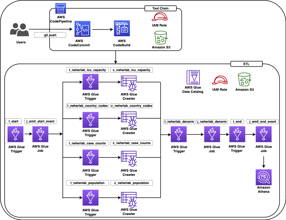
The solution constructs a CI/CD pipeline with multiple stages. The CI/CD pipeline constructs a data pipeline using COVID-19 Harmonized Data managed by Talend / Stitch. The data pipeline crawls the datasets provided by neherlab from the public Amazon Simple Storage Service (Amazon S3) bucket, exposes the public datasets in the AWS Glue Data Catalog so they’re available for SQL queries using Amazon Athena, performs ETL (extract, transform, and load) transformations to denormalize the datasets to a table, and makes the denormalized table available in the Data Catalog.

The solution is designed as follows:

  • A data engineer deploys the initial solution. The solution creates two stacks:
    • cdk-covid19-glue-stack-pipeline – This stack creates the CI/CD infrastructure as shown in the architectural diagram (labeled Tool Chain).
    • cdk-covid19-glue-stack – The cdk-covid19-glue-stack-pipeline stack deploys the cdk-covid19-glue-stack stack to create the AWS Glue based data pipeline as shown in the diagram (labeled ETL).
  • The data engineer makes changes on cdk-covid19-glue-stack (when a change in the ETL application is required).
  • The data engineer pushes the change to a CodeCommit repository (generated in the cdk-covid19-glue-stack-pipeline stack).
  • The pipeline is automatically triggered by the push, and deploys and updates all the resources in the cdk-covid19-glue-stack stack.

At the time of publishing of this post, the AWS CDK has two versions of the AWS Glue module: @aws-cdk/aws-glue and @aws-cdk/aws-glue-alpha, containing L1 constructs and L2 constructs, respectively. At this time, the @aws-cdk/aws-glue-alpha module is still in an experimental stage. We use the stable @aws-cdk/aws-glue module for the purpose of this post.

The following diagram shows all the components in the solution.

BDB-2467-architecture-diagram

Figure 1 – Architecture diagram

The data pipeline consists of an AWS Glue workflow, triggers, jobs, and crawlers. The AWS Glue job uses an AWS Identity and Access Management (IAM) role with appropriate permissions to read and write data to an S3 bucket. AWS Glue crawlers crawl the data available in the S3 bucket, update the AWS Glue Data Catalog with the metadata, and create tables. You can run SQL queries on these tables using Athena. For ease of identification, we followed the naming convention for triggers to start with t_*, crawlers with c_*, and jobs with j_*. A CI/CD pipeline based on CodeCommit, CodeBuild, and CodePipeline builds, tests and deploys the solution. The complete infrastructure is created using the AWS CDK.

The following table lists the tables created by this solution that you can query using Athena.

Table Name Description Dataset Location Access Location
neherlab_case_counts Total number of cases s3://covid19-harmonized-dataset/covid19tos3/neherlab_case_counts/ Read Public
neherlab_country_codes Country code s3://covid19-harmonized-dataset/covid19tos3/neherlab_country_codes/ Read Public
neherlab_icu_capacity Intensive Care Unit (ICU) capacity s3://covid19-harmonized-dataset/covid19tos3/neherlab_icu_capacity/ Read Public
neherlab_population Population s3://covid19-harmonized-dataset/covid19tos3/neherlab_population/ Read Public
neherla_denormalized Denormalized table that combines all the preceding tables into one table s3://<your-S3-bucket-name>/neherlab_denormalized Read/Write Reader’s AWS account

Anatomy of the AWS CDK application

In this section, we visit key concepts and anatomy of the AWS CDK application, review the important sections of the code, and discuss how the AWS CDK reduces complexity of the solution as compared to AWS CloudFormation.

An AWS CDK app defines one or more stacks. Stacks (equivalent to CloudFormation stacks) contain constructs, each of which defines one or more concrete AWS resources. Each stack in the AWS CDK app is associated with an environment. An environment is the target AWS account ID and Region into which the stack is intended to be deployed.

In the AWS CDK, the top-most object is the AWS CDK app, which contains multiple stacks vs. the top-level stack in AWS CloudFormation. Given this difference, you can define all the stacks required for the application in the AWS CDK app. In AWS Glue based ETL projects, developers need to define multiple data pipelines by subject area or business logic. In AWS CloudFormation, we can achieve this by writing multiple CloudFormation stacks and often deploy them independently. In some cases, developers write nested stacks, which over time becomes very large and complicated to maintain. In the AWS CDK, all stacks are deployed from the AWS CDK app, increasing modularity of the code and allowing developers to identify all the data pipelines associated with an application easily.

Our AWS CDK application consists of four main files:

  • app.py – This is the AWS CDK app and the entry point for the AWS CDK application
  • pipeline.py – The pipeline.py stack, invoked by app.py, creates the CI/CD pipeline
  • etl/infrastructure.py – The etl/infrastructure.py stack, invoked by pipeline.py, creates the AWS Glue based data pipeline
  • default-config.yaml – The configuration file contains the AWS account ID and Region.

The AWS CDK application reads the configuration from the default-config.yaml file, sets the environment information (AWS account ID and Region), and invokes the PipelineCDKStack class in pipeline.py. Let’s break down the preceding line and discuss the benefits of this design.

For every application, we want to deploy in pre-production environments and a production environment. The application in all the environments will have different configurations, such as the size of the deployed resources. In the AWS CDK, every stack has a property called env, which defines the stack’s target environment. This property receives the AWS account ID and Region for the given stack.

Lines 26–34 in app.py show the aforementioned details:

# Initiating the CodePipeline stack
PipelineCDKStack(
app,
"PipelineCDKStack",
config=config,
env=env,
stack_name=config["codepipeline"]["pipelineStackName"]
)

The env=env line sets the target AWS account ID and Region for PipelieCDKStack. This design allows an AWS CDK app to be deployed in multiple environments at once and increases the parity of the application in all environment. For our example, if we want to deploy PipelineCDKStack in multiple environments, such as development, test, and production, we simply call the PipelineCDKStack stack after populating the env variable appropriately with the target AWS account ID and Region. This was more difficult in AWS CloudFormation, where developers usually needed to deploy the stack for each environment individually. The AWS CDK also provides features to pass the stage at the command line. We look into this option and usage in the later section.

Coming back to the AWS CDK application, the PipelineCDKStack class in pipeline.py uses the aws_cdk.pipeline construct library to create continuous delivery of AWS CDK applications. The AWS CDK provides multiple opinionated construct libraries like aws_cdk.pipeline to reduce boilerplate code from an application. The pipeline.py file creates the CodeCommit repository, populates the repository with the sample code, and creates a pipeline with the necessary AWS CDK stages for CodePipeline to run the CdkGlueBlogStack class from the etl/infrastructure.py file.

Line 99 in pipeline.py invokes the CdkGlueBlogStack class.

The CdkGlueBlogStack class in etl/infrastructure.py creates the crawlers, jobs, database, triggers, and workflow to provision the AWS Glue based data pipeline.

Refer to line 539 for creating a crawler using the CfnCrawler construct, line 564 for creating jobs using the CfnJob construct, and line 168 for creating the workflow using the CfnWorkflow construct. We use the CfnTrigger construct to stitch together multiple triggers to create the workflow. The AWS CDK L1 constructs expose all the available AWS CloudFormation resources and entities using methods from popular programing languages. This allows developers to use popular programing languages to provision resources instead of working with JSON or YAML files in AWS CloudFormation.

Refer to etl/infrastructure.py for additional details.

Walkthrough of the CI/CD pipeline

In this section, we walk through the various stages of the CI/CD pipeline. Refer to CDK Pipelines: Continuous delivery for AWS CDK applications for additional information.

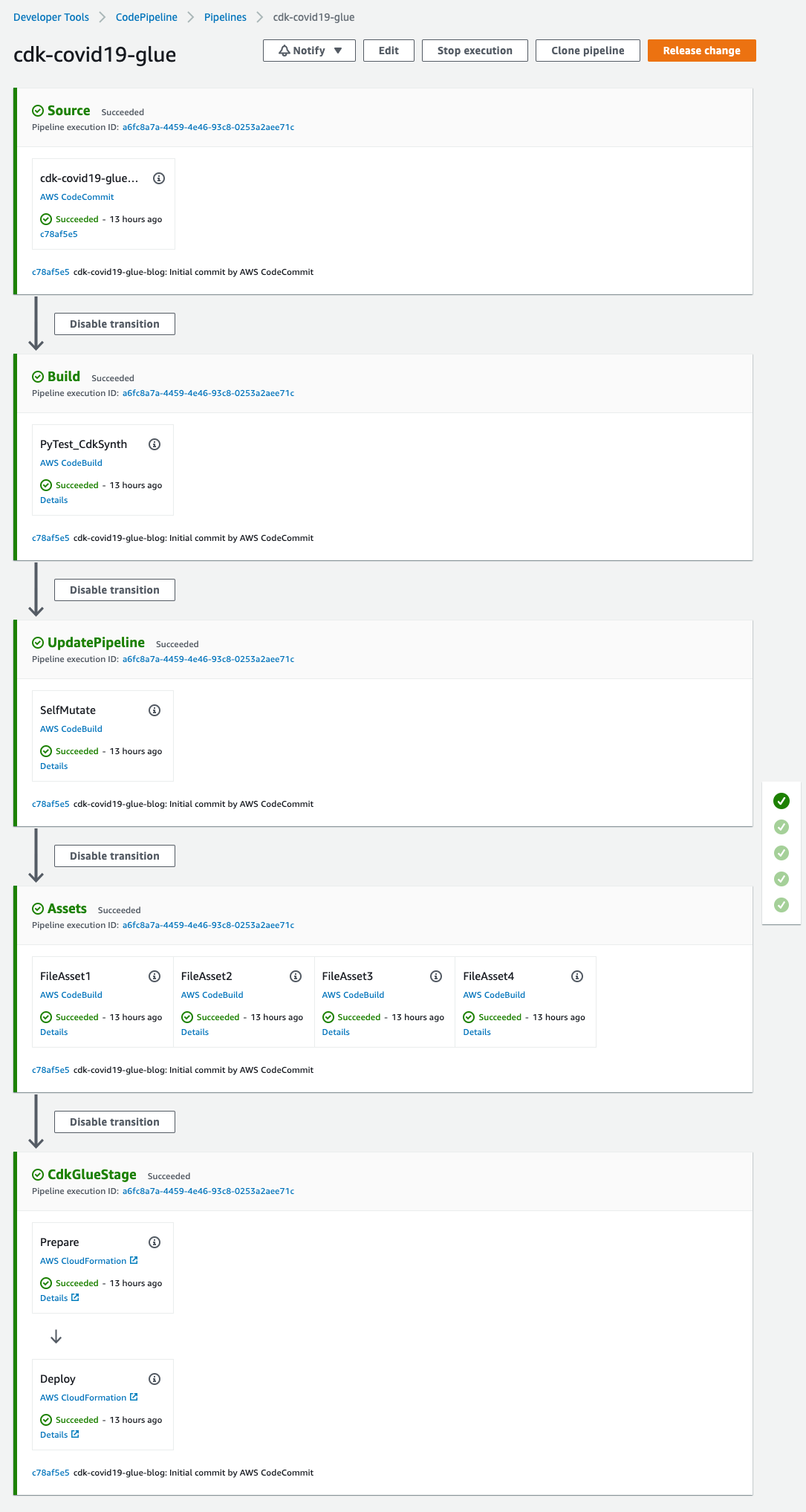
  • Source – This stage fetches the source of the AWS CDK app from the CodeCommit repo and triggers the pipeline every time a new commit is made.
  • Build – This stage compiles the code (if necessary), runs the tests, and performs a cdk synth. The output of the step is a cloud assembly, which is used to perform all the actions in the rest of the pipeline. The pytest is run using the amazon/aws-glue-libs:glue_libs_3.0.0_image_01 Docker image. This image comes with all the required libraries to run tests for AWS Glue version 3.0 jobs using a Docker container. Refer to Develop and test AWS Glue version 3.0 jobs locally using a Docker container for additional information.
  • UpdatePipeline – This stage modifies the pipeline if necessary. For example, if the code is updated to add a new deployment stage to the pipeline or add a new asset to your application, the pipeline is automatically updated to reflect the changes.
  • Assets – This stage prepares and publishes all AWS CDK assets of the app to Amazon S3 and all Docker images to Amazon Elastic Container Registry (Amazon ECR). When the AWS CDK deploys an app that references assets (either directly by the app code or through a library), the AWS CDK CLI first prepares and publishes the assets to Amazon S3 using a CodeBuild job. This AWS Glue solution creates four assets.
  • CDKGlueStage – This stage deploys the assets to the AWS account. In this case, the pipeline deploys the AWS CDK template etl/infrastructure.py to create all the AWS Glue artifacts.

Code

The code can be found at AWS Samples on GitHub.

Prerequisites

This post assumes you have the following:

Deploy the solution

To deploy the solution, complete the following steps:

  • Download the source code from the AWS Samples GitHub repository to the client machine:
$ git clone [email protected]:aws-samples/aws-glue-cdk-cicd.git
  • Create the virtual environment:
$ cd aws-glue-cdk-cicd 
$ python3 -m venv .venv

This step creates a Python virtual environment specific to the project on the client machine. We use a virtual environment in order to isolate the Python environment for this project and not install software globally.

  • Activate the virtual environment according to your OS:
    • On MacOS and Linux, use the following code:
$ source .venv/bin/activate
    • On a Windows platform, use the following code:
% .venv\Scripts\activate.bat

After this step, the subsequent steps run within the bounds of the virtual environment on the client machine and interact with the AWS account as needed.

  • Install the required dependencies described in requirements.txt to the virtual environment:
$ pip install -r requirements.txt
  • Bootstrap the AWS CDK app:
cdk bootstrap

This step populates a given environment (AWS account ID and Region) with resources required by the AWS CDK to perform deployments into the environment. Refer to Bootstrapping for additional information. At this step, you can see the CloudFormation stack CDKToolkit on the AWS CloudFormation console.

  • Synthesize the CloudFormation template for the specified stacks:
$ cdk synth # optional if not default (-c stage=default)

You can verify the CloudFormation templates to identify the resources to be deployed in the next step.

  • Deploy the AWS resources (CI/CD pipeline and AWS Glue based data pipeline):
$ cdk deploy # optional if not default (-c stage=default)

At this step, you can see CloudFormation stacks cdk-covid19-glue-stack-pipeline and cdk-covid19-glue-stack on the AWS CloudFormation console. The cdk-covid19-glue-stack-pipeline stack gets deployed first, which in turn deploys cdk-covid19-glue-stack to create the AWS Glue pipeline.

Verify the solution

When all the previous steps are complete, you can check for the created artifacts.

CloudFormation stacks

You can confirm the existence of the stacks on the AWS CloudFormation console. As shown in the following screenshot, the CloudFormation stacks have been created and deployed by cdk bootstrap and cdk deploy.

BDB-2467-cloudformation-stacks

Figure 2 – AWS CloudFormation stacks

CodePipeline pipeline

On the CodePipeline console, check for the cdk-covid19-glue pipeline.

BDB-2467-code-pipeline-summary

Figure 3 – AWS CodePipeline summary view

You can open the pipeline for a detailed view.

BDB-2467-code-pipeline-detailed

Figure 4 – AWS CodePipeline detailed view

AWS Glue workflow

To validate the AWS Glue workflow and its components, complete the following steps:

  • On the AWS Glue console, choose Workflows in the navigation pane.
  • Confirm the presence of the Covid_19 workflow.
BDB-2467-glue-workflow-summary

Figure 5 – AWS Glue Workflow summary view

You can select the workflow for a detailed view.

BDB-2467-glue-workflow-detailed

Figure 6 – AWS Glue Workflow detailed view

  • Choose Triggers in the navigation pane and check for the presence of seven t-* triggers.
BDB-2467-glue-triggers

Figure 7 – AWS Glue Triggers

  • Choose Jobs in the navigation pane and check for the presence of three j_* jobs.
BDB-2467-glue-jobs

Figure 8 – AWS Glue Jobs

The jobs perform the following tasks:

    • etlScripts/j_emit_start_event.py – A Python job that starts the workflow and creates the event
    • etlScripts/j_neherlab_denorm.py – A Spark ETL job to transform the data and create a denormalized view by combining all the base data together in Parquet format
    • etlScripts/j_emit_ended_event.py – A Python job that ends the workflow and creates the specific event
  • Choose Crawlers in the navigation pane and check for the presence of five neherlab-* crawlers.
BDB-2467-glue-crawlers

Figure 9 – AWS Glue Crawlers

Execute the solution

  • The solution creates a scheduled AWS Glue workflow which runs at 10:00 AM UTC on day 1 of every month. A scheduled workflow can also be triggered on-demand. For the purpose of this post, we will execute the workflow on-demand using the following command from the AWS CLI. If the workflow is successfully started, the command returns the run ID. For instructions on how to run and monitor a workflow in Amazon Glue, refer to Running and monitoring a workflow in Amazon Glue.
aws glue start-workflow-run --name Covid_19
  • You can verify the status of a workflow run by execution the following command from the AWS CLI. Please use the run ID returned from the above command. A successfully executed Covid_19 workflow should return a value of 7 for SucceededActions  and 0 for FailedActions.
aws glue get-workflow-run --name Covid_19 --run-id <run_ID>
  • A sample output of the above command is provided below.
{
"Run": {
"Name": "Covid_19",
"WorkflowRunId": "wr_c8855e82ab42b2455b0e00cf3f12c81f957447abd55a573c087e717f54a4e8be",
"WorkflowRunProperties": {},
"StartedOn": "2022-09-20T22:13:40.500000-04:00",
"CompletedOn": "2022-09-20T22:21:39.545000-04:00",
"Status": "COMPLETED",
"Statistics": {
"TotalActions": 7,
"TimeoutActions": 0,
"FailedActions": 0,
"StoppedActions": 0,
"SucceededActions": 7,
"RunningActions": 0
}
}
}
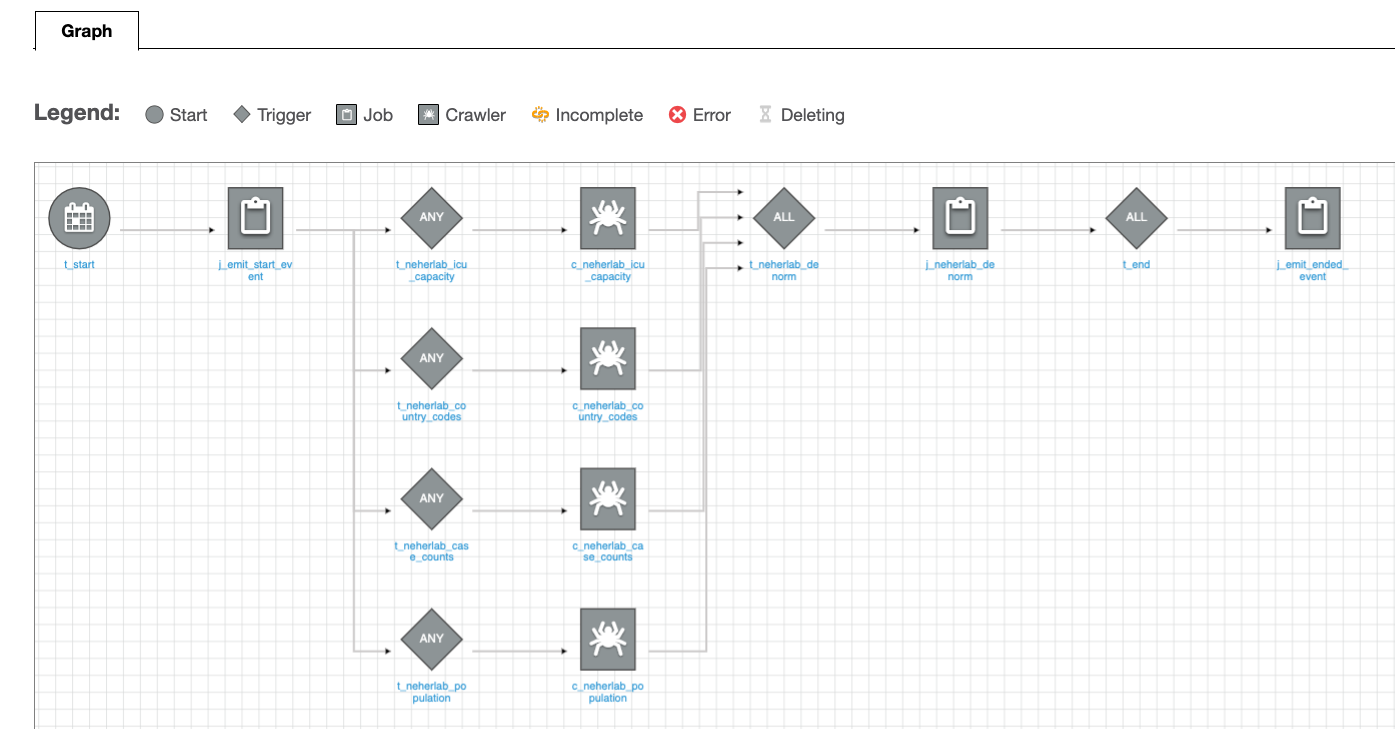
  • (Optional) To verify the status of the workflow run using AWS Glue console, choose Workflows in the navigation pane, select the Covid_19 workflow, click on the History tab, select the latest row and click on View run details. A successfully completed workflow is marked in green check marks. Please refer to the Legend section in the below screenshot for additional statuses.

    BDB-2467-glue-workflow-success

    Figure 10 – AWS Glue Workflow successful run

Check the output

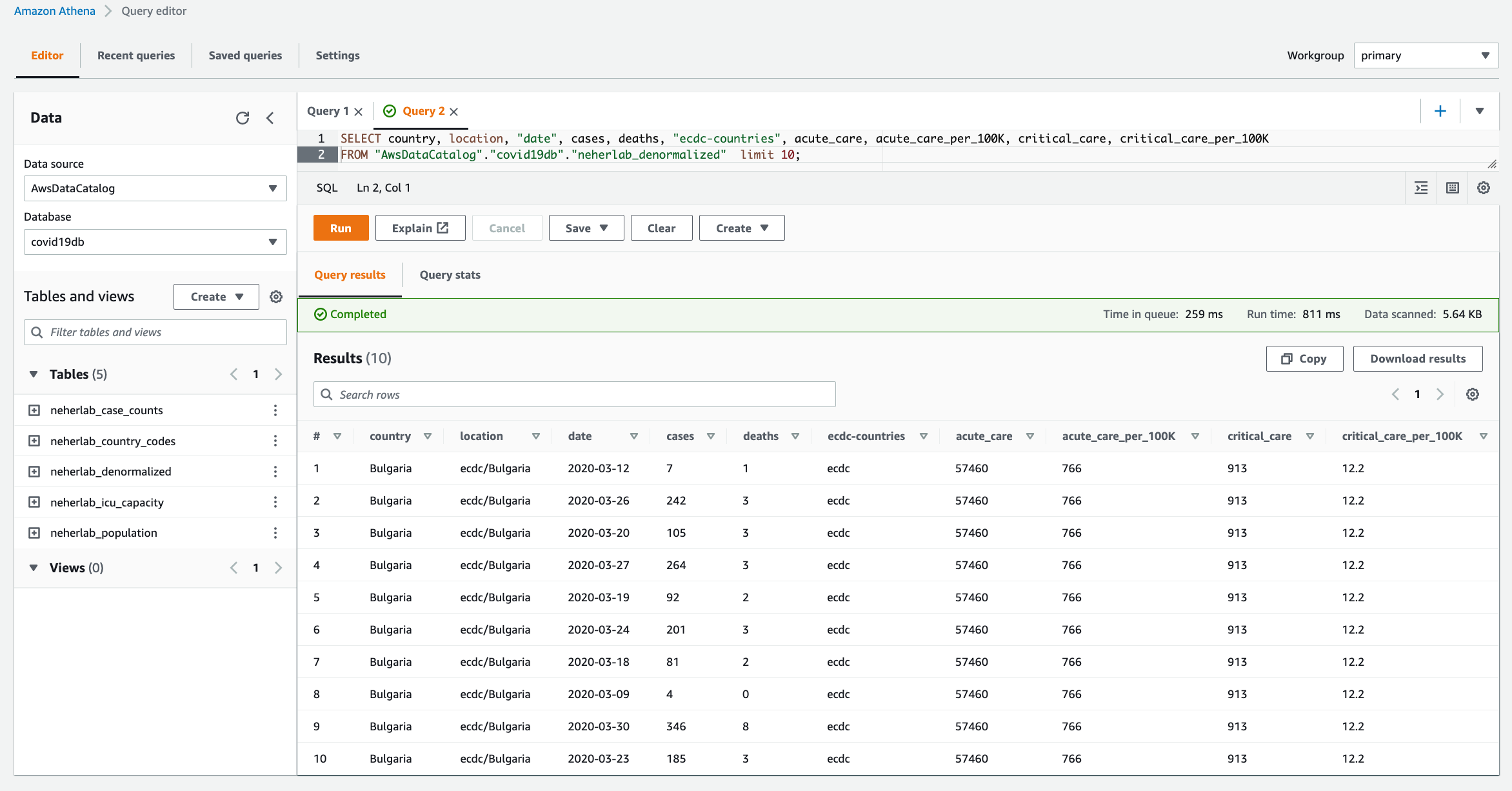
  • When the workflow is complete, navigate to the Athena console to check the successful creation and population of neherlab_denormalized table. You can run SQL queries against all 5 tables to check the data. A sample SQL query is provided below.
SELECT "country", "location", "date", "cases", "deaths", "ecdc-countries",
        "acute_care", "acute_care_per_100K", "critical_care", "critical_care_per_100K" 
FROM "AwsDataCatalog"."covid19db"."neherlab_denormalized"
limit 10;
BDB-2467-athena

Figure 10 – Amazon Athena

Clean up

To clean up the resources created in this post, delete the AWS CloudFormation stacks in the following order:

  • cdk-covid19-glue-stack
  • cdk-covid19-glue-stack-pipeline
  • CDKToolkit

Then delete all associated S3 buckets:

  • cdk-covid19-glue-stack-p-pipelineartifactsbucketa-*
  • cdk-*-assets-<AWS_ACCOUNT_ID>-<AWS_REGION>
  • covid19-glue-config-<AWS_ACCOUNT_ID>-<AWS_REGION>
  • neherlab-denormalized-dataset-<AWS_ACCOUNT_ID>-<AWS_REGION>

Conclusion

In this post, we demonstrated a step-by-step guide to define, test, provision, and manage changes to an AWS Glue based ETL solution using the AWS CDK. We used an AWS Glue example, which has all the components to build a complex ETL solution, and demonstrated how to integrate individual AWS Glue components into a frictionless CI/CD pipeline. We encourage you to use this post and associated code as the starting point to build your own CI/CD pipelines for AWS Glue based ETL solutions.


About the authors

Puneet Babbar is a Data Architect at AWS, specialized in big data and AI/ML. He is passionate about building products, in particular products that help customers get more out of their data. During his spare time, he loves to spend time with his family and engage in outdoor activities including hiking, running, and skating. Connect with him on LinkedIn.

Suvojit Dasgupta is a Sr. Lakehouse Architect at Amazon Web Services. He works with customers to design and build data solutions on AWS.

Justin Kuskowski is a Principal DevOps Consultant at Amazon Web Services. He works directly with AWS customers to provide guidance and technical assistance around improving their value stream, which ultimately reduces product time to market and leads to a better customer experience. Outside of work, Justin enjoys traveling the country to watch his two kids play soccer and spending time with his family and friends wake surfing on the lakes in Michigan.

Hazard analysis and Chaos engineering at Vanguard Group

Post Syndicated from Jason Barto original https://aws.amazon.com/blogs/devops/hazard-analysis-and-chaos-engineering-at-vanguard-group/

Anticipating events that can cause a disruption to your system’s service is critical to building highly available, reliable systems.  Hazard analysis gives you a method to identify such events.  Chaos engineering gives you a method to confirm that a system behaves as expected in adverse conditions.  By combining these methods, Vanguard is building reliability into their systems.

Vanguard engineering teams perform hazard analysis on their systems and capture the identified events as failure scenarios.  They use the identified failure scenarios to create hypotheses to support chaos engineering experiments.  These hypotheses predict how the system will respond to failures and each hypothesis is then confirmed through experimentation to increase the team’s confidence in the system’s reliability.

In this article we will walk you through how Vanguard uses hazard analysis and chaos engineering.  We will also provide guidance on how you can employ these techniques on your applications.

Failure Mode & Effects Analysis

A hazard analysis can be performed using different methods.  At Vanguard, they have adapted the failure mode & effects analysis (FMEA) method to support their important services.

FMEA is a bottom-up approach to analyse an architecture and focus on the impact to system functions when one or more components of the system are disrupted. Members of the engineering team and architects responsible for designing and building a system brainstorm possible failure scenarios or failure modes, and document the impact of these failures on the system. Combined with a quantitative method for ranking the failure modes, the analysis process produces a prioritised list of failure modes which describes how the system would respond to individual or combined failures in its component parts or dependencies.

For each failure mode the team conducting the analysis will highlight what protections exist within the system to guard against the failure mode.  Sometimes, fault isolation boundaries have been put in place to prevent client impact in failure scenarios. In other scenarios, for one reason or another, there are hard dependencies in place for which the engineering team has decided not to build in fault tolerance. For example, a team responsible for a less-critical function may have architected its system to operate across multiple availability zones, but could decide not to implement other mitigations to prioritize cost over increased resilience.

The FMEA method has been in use by engineers in the automotive, aeronautical, healthcare, and military industries for more than 60 years.  Over that time, FMEA has been modified to best suit the organization and the field in which it was applied.  In many variations the FMEA measures each failure mode with a risk priority number (RPN), which is intended to quantitatively rank the failure mode based upon:

  1. The failure mode’s impact to the system as a whole
  2. The probability of the failure mode’s occurrence
  3. How easily the failure mode can be detected

Vanguard have adapted the FMEA process to serve their own specific requirements and processes.  Vanguard have decided not to adopt the RPN element of the FMEA process, as teams found they spent a lot of time debating the impact, probability, and detectability of individual failure modes.  To perform an FMEA more quickly, teams instead focus on the failure modes and system impact only, documenting a mental model of system performance which can be experimented through chaos engineering.

An excerpt of a Vanguard FMEA output is provided as an example in the following table:

The “Process Step” in the table above refers to a business function of the system being analyzed, for example “Request to retrieve stored data”. As part of the analysis, the team identifies the system components needed to perform the Process Step and considers the interactions of those components Focusing on a Process Step makes it easier to anticipate the failure scenarios that would affect the system in performing this particular business function. Also, the Process Step will imply an importance or criticality which can be a factor when prioritizing mitigations.

After selecting a Process Step, you walk through the system components involved and identify how component failures or disruptions will affect the wider system. Such component failures may involve individual components or a combination of components and are captured as “Failure Mode”. This identifies the component or components that are disrupted and their behaviour; for example, “Microservice is unavailable or returns an error”.

“Expected Behaviour” describes the effect of the failure mode on the wider system, in the context of the Process Step. This captures what other system components are affected by the Failure Mode and why, and how this impacts the Process Step as a whole.

Lastly, the “Hypothesis” column forms the basis for the chaos experiments that will follow from the FMEA to confirm that the system performs as expected.

At Vanguard, all mission-critical product teams are conducting FMEAs for their production applications. The outputs of these sessions are maintained over time and serve multiple purposes:

  1. When onboarding new team members, it is helpful to provide the FMEA document alongside an architecture diagram and narrative. It will paint a more robust picture of how the system is intended to operate in both “happy path” and “unhappy path” scenarios.
  2. When troubleshooting incidents, an FMEA document can help on-call engineers – especially those less experienced with debugging – to match up the documented expectations to the observed system behavior.
  3. Site Reliability Engineers (SREs) looking for opportunities to improve the resilience of a system might look to FMEA documentation to understand the existing fault isolation boundaries and introduce additional resilience mechanisms through automation and system changes.
  4. Finally, when selecting scenarios for experimentation with Chaos Engineering, the FMEA document provides a list of conjectures that have been mapped to hypotheses, ready to be validated through experimentation. This input into the Chaos Engineering workflow is the primary use of FMEA documents for Vanguard product teams.

There are many resources available online to learn more about how FMEA is used and applied in other organisations. In Failure Modes and Continuous Resilience, Adrian Cockcroft introduces FMEA as a method for anticipating failure scenarios. The NASA Software Engineering Handbook details how FMEAs are conducted as part of their engineering process. The Automotive Industry Group has also formally documented the use of FMEA in the Automotive Industry Action Group FMEA Handbook.

Chaos Engineering

After failure modes have been identified and mitigated through system design, it’s time to understand how resilient the system’s implementation is to those failure modes. Chaos engineering can be used to explore a system and validate that a system’s implementation meets business resiliency objectives.

Chaos engineering helps to improve a team’s mental model about the system under experimentation and provides insights into how a complex system behaves under adverse conditions. It also enables an engineer to find the unknown unknowns and the known unknowns through experiments that are built on top of the hypothesis. These experiments should simulate real world events, such as network degradation and increased client requests, and the outcome of the experiment should not be known. In other words, an experiment is not an experiment if it’s known that the conditions will cause the system to fail.

Prerequisites to Chaos Experiments at Vanguard

At Vanguard, there are some necessary prerequisites to running a chaos experiment. Firstly, the system under experiment must be set up with some basic observability tooling that will allow teams to monitor the state of the application during the failure injection. This could be as simple as an Amazon CloudWatch dashboard and some associated alarms, or as elaborate as a dedicated dashboard set up in a vendor tool.

Secondly, teams must be able to drive load to the application during the experiment; depending on the experiment type, the level and type of load may vary. The load generator can be as simple as a script on someone’s machine, or a fully automated load test depending on the requirements of the hypothesis.

Finally, teams need to have a good understanding of what the application’s “steady state” looks like. I Ideally, this takes the form of some metrics such as expected error rate, expected latency, and/or a service level objective (SLO) that can be monitored throughout the duration of the experiment. For example, a service level objective for a RESTful API might be that 90% of requests should receive a response within 100 milliseconds.

With the prerequisites met and a completed FMEA, teams can then experiment with their hypothesis using various experiment templates defined by Vanguard’s Climate of Chaos tooling.

Vanguard’s Climate of Chaos

At Vanguard, ensuring its software systems are resilient to adverse events is a critical part of its ongoing mission to provide world-class service to their clients. Vanguard believes that in order to develop high quality software, one must plan for the inevitable “stormy weather” events that occur in a distributed system.

Over the past 2 years, as a response to this need, Vanguard has developed in-house tooling called “The Climate of Chaos” to give teams easy access to common experiment templates, along with a friendly UI interface. The Climate of Chaos helps developers experiment on their systems and validate the hypotheses generated from FMEAs. It also provides the tooling for them to simulate the most common failure scenarios on Vanguard’s most commonly utilized AWS infrastructure, including Amazon Elastic Container Service (Amazon ECS), AWS Fargate, Amazon DynamoDB, Amazon Relational Database Service (Amazon RDS), AWS Lambda, and others.

The Climate of Chaos was created prior to Amazon’s release of the AWS Fault Injection Simulator (FIS), and today there is a lot of overlap with the experiment capabilities available in FIS. The Climate of Chaos has also been enhanced with company-specific features and integrations that make it easier for Vanguard developers to run chaos experiments in a controlled and predictable manner.

The Climate of Chaos includes important safety features such as an “emergency stop” function. This feature enables teams to terminate the experiment immediately if unintended side effects are encountered, rolling back the events simulated to resume steady state operation. The Climate of Chaos has been coupled with other systems like an in-house load testing tooling and added features like the ability to monitor CloudWatch alarms. Vanguard also offers teams the ability to schedule experiments to run at their convenience. Soon, Vanguard hopes to make running chaos experiments even smarter, introducing tools that will help teams run bulk experiments that systematically inject failures on a group of related applications to help pinpoint more complex failure modes.

Next Steps

Failure modes and effects analysis is a hazard analysis method which can help you identify single and combined points of failure in your system so you can prioritize the failure modes. To learn more about the FMEA process, you can read the NASA Software Engineering Handbook which outlines how they perform FMEA on their software-based systems. The AWS Whitepaper Building Mission-Critical Financial Services Applications on AWS provides example forms and suggestions for severity, probability, and detectability rankings. Appendix F in the whitepaper suggests a 1 to 10 ranking for each Risk Priority Number input, and the example spreadsheets recommend performing FMEAs for the application, platform, infrastructure, and operation layers of the system. Using these examples, you can perform an analysis of your own systems and generate hypotheses.

To experiment on your systems and validate your own hypotheses, you can use the AWS Fault Injection Simulator (FIS) mentioned earlier in this article. FIS provides you with a framework for performing controlled chaos experiments on your AWS workloads. It helps you to safely manage your experiments by providing tooling to monitor, rollback, and orchestrate chaos experiments. FIS provides the fault injection mechanisms that you will need to experiment upon your system’s implementation and resilience to identified failure modes. You can start by running experiments in pre-production environments, and then step up to running them as part of your CI/CD workflow and ultimately in your production environment. To learn more about FIS, you can read the FIS User Guide and FIS tutorials.

By using FMEA to anticipate the failures and experimenting on your systems with chaos engineering, you will gain confidence in the reliability of your system.

The content and opinions in this post are those of The Vanguard Group and AWS is not responsible for the content or accuracy of this post.

About the authors:

Tory Benya

Tory works as a Chaos Engineering Tech Lead at Vanguard.  She is passionate about automation, data, and making software work for people.  She likes to automate, integrate, and improve processes and technology.  Tory makes data-driven decisions to make a difference as part of her team at Vanguard.

Christina Yakomin

Christina works as a Senior Site Reliability Engineering Specialist in Vanguard’s Chief Technology Office. Throughout her career, she has developed an expansive skill set in front- and back-end web development, as well as cloud infrastructure and automation, with a specialization in Site Reliability Engineering. She has earned several Amazon Web Services certifications, including the Solutions Architect – Professional. Christina has also worked closely with the Women’s Initiative for Leadership Success at Vanguard, both internally at the company and externally in the local community, to further the career advancement of women and girls – in particular within the tech industry.

Jason Barto

Jason works as a Principal Solutions Architect at AWS where he works with customers to design resilient system architectures and develop chaos engineering practices. Prior to joining AWS Jason was designing and building distributed systems for complex event processing and real-time telemetry analytics.

John Formento

John is a Solutions Architect at AWS. He helps large enterprises achieve their goals by architecting secure and scalable solutions on the AWS Cloud. John holds 7 AWS certifications including AWS Certified Solutions Architect – Professional and DevOps Engineer – Professional.

DevOps with serverless Jenkins and AWS Cloud Development Kit (AWS CDK)

Post Syndicated from sangusah original https://aws.amazon.com/blogs/devops/devops-with-serverless-jenkins-and-aws-cloud-development-kit-aws-cdk/

The objective of this post is to walk you through how to set up a completely serverless Jenkins environment on AWS Fargate using AWS Cloud Development Kit (AWS CDK).

Jenkins is a popular open-source automation server that provides hundreds of plugins to support building, testing, deploying, and automation. Jenkins uses a controller-agent architecture in which the controller is responsible for serving the web UI, stores the configurations and related data on disk, and delegates the jobs to the worker agents that run these jobs as their primary responsibility.

Amazon Elastic Container Service (Amazon ECS)  using Fargate is a fully-managed container orchestration service that helps you easily deploy, manage, and scale containerized applications. It deeply integrates with the rest of the AWS platform to provide a secure and easy-to-use solution for running container workloads in the cloud and now on your infrastructure. Fargate is a serverless, pay-as-you-go compute engine that lets you focus on building applications without managing servers. Fargate is compatible with both Amazon ECS and Amazon Elastic Kubernetes Service (Amazon EKS).

Solution overview

The following diagram illustrates the solution architecture. The dashed lines indicate the AWS CDK deployment.

Figure 1 This diagram shows AWS CDK and how it deploys using AWS CloudFormation to create the Elastic Load Balancer, AWS Fargate, and Amazon EFS

Figure 1 This diagram shows AWS CDK and how it deploys using AWS CloudFormation to create the Elastic Load Balancer, AWS Fargate, and Amazon EFS

You’ll be using the following:

  1. The Jenkins controller URL backed by an Application Load Balancer (ALB).
  2. You’ll be using your default Amazon Virtual Private Cloud (Amazon VPC) for this example.
  3. The Jenkins controller runs as a service in Amazon ECS using Fargate as the launch type. You’ll use Amazon Elastic File System (Amazon EFS) as the persistent backing store for the Jenkins controller task. The Jenkins controller and Amazon EFS are launched in private subnets.

Prerequisites

For this post, you’ll utilize AWS CDK using TypeScript.

Follow the guide on Getting Started for AWS CDK to:

  • Get your local environment setup
  • Bootstrap your development account

Code

Let’s review the code used to define the Jenkins environment in AWS using the AWS CDK.

Setup your imports

import { Duration, IResource, RemovalPolicy, Stack, Tags } from 'aws-cdk-lib';
import { Construct } from 'constructs';

import * as cdk from 'aws-cdk-lib';

import * as ecs from 'aws-cdk-lib/aws-ecs';
import * as efs from 'aws-cdk-lib/aws-efs';
import { Port } from 'aws-cdk-lib/aws-ec2';
import * as elbv2 from 'aws-cdk-lib/aws-elasticloadbalancingv2';

Setup your Amazon ECS, which is a logical grouping of tasks or services and set vpc

export class AppStack extends Stack {
  constructor(scope: Construct, id: string, props?: cdk.StackProps) {
    super(scope, id, props);

    const jenkinsHomeDir: string = 'jenkins-home';
    const appName: string = 'jenkins-cdk';

    const cluster = new ecs.Cluster(this, `${appName}-cluster`, {
      clusterName: appName,
    });

    const vpc = cluster.vpc;

Setup Amazon EFS to store the data

    const fileSystem = new efs.FileSystem(this, `${appName}-efs`, {
      vpc: vpc,
      fileSystemName: appName,
      removalPolicy: RemovalPolicy.DESTROY,
    });

Setup Access Point, which are application-specific entry points into an Amazon EFS file system that makes it easier to manage application access to shared datasets

const accessPoint = fileSystem.addAccessPoint(`${appName}-ap`, {
      path: `/${jenkinsHomeDir}`,
      posixUser: {
        uid: '1000',
        gid: '1000',
      },
      createAcl: {
        ownerGid: '1000',
        ownerUid: '1000',
        permissions: '755',
      },
    });

Setup Task Definition to run Docker containers in Amazon ECS

const taskDefinition = new ecs.FargateTaskDefinition(
      this,
      `${appName}-task`,
      {
        family: appName,
        cpu: 1024,
        memoryLimitMiB: 2048,
      }
    );

Setup a Volume mapping the Amazon EFS from above to the Task Definition

taskDefinition.addVolume({
      name: jenkinsHomeDir,
      efsVolumeConfiguration: {
        fileSystemId: fileSystem.fileSystemId,
        transitEncryption: 'ENABLED',
        authorizationConfig: {
          accessPointId: accessPoint.accessPointId,
          iam: 'ENABLED',
        },
      },
    });

Setup the Container using the Task Definition and the Jenkins image from the registry

const containerDefinition = taskDefinition.addContainer(appName, {
      image: ecs.ContainerImage.fromRegistry('jenkins/jenkins:lts'),
      logging: ecs.LogDrivers.awsLogs({ streamPrefix: 'jenkins' }),
      portMappings: [{ containerPort: 8080 }],
    });

Setup Mount Points to bind ephemeral storage to the container

containerDefinition.addMountPoints({
      containerPath: '/var/jenkins_home',
      sourceVolume: jenkinsHomeDir,
      readOnly: false,
    });

Setup Fargate Service to run the container serverless

    const fargateService = new ecs.FargateService(this, `${appName}-service`, {
      serviceName: appName,
      cluster: cluster,
      taskDefinition: taskDefinition,
      desiredCount: 1,
      maxHealthyPercent: 100,
      minHealthyPercent: 0,
      healthCheckGracePeriod: Duration.minutes(5),
    });
    fargateService.connections.allowTo(fileSystem, Port.tcp(2049));

Setup ALB and add listener to checks for connection requests, using the protocol and port that you configure.

    const loadBalancer = new elbv2.ApplicationLoadBalancer(
      this,
      `${appName}-elb`,
      {
        loadBalancerName: appName,
        vpc: vpc,
        internetFacing: true,
      }
    );
    const lbListener = loadBalancer.addListener(`${appName}-listener`, {
      port: 80,
    });

Setup Target to route requests to Jenkins running on Amazon ECS using Fargate

const loadBalancerTarget = lbListener.addTargets(`${appName}-target`, {
      port: 8080,
      targets: [fargateService],
      deregistrationDelay: Duration.seconds(10),
      healthCheck: { path: '/login' },
    });
  }
}

Jenkins Deployment

Now that you have all the code, let’s deploy the AWS CDK definition:

  1. Make sure that you have done the Prerequisite steps from earlier.
  2. Install packages by running the following command in your IDE CLI:
npm i
  1. Now you’ll deploy your AWS CDK definition to your dev account:
cdk deploy

Let’s now login to Jenkins

  1. In your browser, use the DNS Name from the deployed Load Balancer
  2. In Amazon CloudWatch, there will be a Log group that will be created that is associated to Cluster Service.
    1. Go into that log and you’ll see it output the Password to login to Jenkins
  1. In Jenkins, follow the wizard to continue the setup

Cleaning up

To avoid incurring future charges, delete the resources.

Let’s destroy our deploy solution

  1. In your IDE CLI:
cdk destroy

Conclusion

With this overview we were able to cover the following:

  • Build an Elastic Load Balancer
  • Use AWS Fargate with a Jenkins AMI
  • All resources running serverlessly
  • All build using the AWS CDK

About the author:

Josh Thornes

Josh Thornes is a Sr. Technical Account Manager at AWS. He works with AWS Partners at any stage of their software-as-a-service (SaaS) journey in order to help build new products, migrate existing applications, or optimize SaaS solutions on AWS. His areas of interest include builder experience (e.g., developer tools, DevOps culture, CI/CD, Front-end, Mobile, Microservices), security, IoT, analytics.

Integrating Cloud Security With DevOps and CI/CD Tools

Post Syndicated from Clint Merrill original https://blog.rapid7.com/2022/09/09/integrating-cloud-security-with-devops-and-ci-cd-tools/

Integrating Cloud Security With DevOps and CI/CD Tools

This is the latest post in our blog series on shifting left in cloud security. In our last post, we kicked off the series with a high-level overview about Rapid7’s approach to shifting cloud security into the application development lifecycle. For this post, we’ll dive into a key aspect of our approach: integrating cloud security with developer and DevOps tooling.

Incentivizing adoption by reducing friction

When integrating security into any part of the development lifecycle there are some important factors to consider, including the security tools you’ll integrate, the processes you’ll ask developers to follow, and how aggressively you intend to enforce certain policies. When making these decisions, it’s important to consider the goals of adopting DevOps practices and infrastructure as code (IaC) respectively: to improve the velocity of application development and delivery, and to empower development teams to provision cloud infrastructure resources on a self-service basis.  

Infusing security into these goals requires guardrails and routine checks to make sure the need for speed doesn’t create vulnerabilities or potentially exploitable misconfigurations. For IaC development, this is accomplished by having individual developers scan templates and plans as early as possible, and at key points in the CI/CD pipeline, before they’re considered for use in staging or production deployment. This is much easier said than done, as it relies on organizational buy-in, particularly from the developers who are typically laser-focused on bringing new products and features to market as fast as possible with the highest quality possible.

As with anything that relies on multiple teams collaborating in a process, the goal is to make it as easy as possible to adopt and demonstrate tangible value to all involved. Shifting security left into the software development lifecycle (SDLC) via developers and CI/CD tool integrations is a perfect application of this. One common example is allowing developers to execute scans on IaC templates or plans prior to a push or pull request, using a local command-line interface (CLI) tool.

The comfort of the CLI

In this context, a CLI tool allows a developer to interact with IaC security scanning features via a terminal prompt for familiarity and convenience. This comfortable experience will encourage adoption by using the CLI rather than engaging with a security product interface or API directly. In late 2021, we released our first CLI tool to initiate IaC scans in InsightCloudSec (ICS): mimics.

mimics has many intended uses that will expand over the time, but for now, the primary goals are:

  1. Enabling developers to execute on-demand security scans of their IaC plans and templates with results delivered directly in the CLI, thereby shortening the discovery and feedback loop for security and compliance issues to the point of immediate remediation
  2. Enabling DevOps teams to easily integrate IaC security scans at any point in the CI/CD workflow, thereby standardizing the process and enforcing security compliance checks and remediation as needed before progressing to the next integration or deployment step

In all cases, the mimics CLI simplifies integration and doesn’t require more costly script-based integration with the ICS API.  In some cases, unique IaC security capabilities are exclusively available via mimics.

Introducing GitHub Actions integration

InsightCloudSec recently launched a GitHub Action to facilitate a bidirectional integration with our IaC scanning feature. Our goal is to streamline the incorporation of IaC security scans into your cloud application CI/CD process governed by GitHub. If you’re not familiar with GitHub Actions, they allow you to automate, customize, and execute workflow steps, including security and compliance checks. In doing so, users can discover, create, and share Actions with other community members.

A great use of the mimics CLI is to integrate with GitHub using our Action to trigger an ICS IaC scan at defined points in your workflow. Upon completion of the scan, you’ll receive an overall pass/fail result in reply, as well as detailed findings, if any, in SARIF format for display in the GitHub Advanced Security module as security alerts. If you don’t subscribe to the GitHub Advance Security module, you can still trigger IaC security scans and receive an overall pass/fail result to govern the workflow step, plus a detailed findings report in one of various readable formats.

More DevOps tool integrations on the way

As you can see, Rapid7’s InsightCloudSec is meeting developers and DevOps teams where they are today and expanding in the near future. We want to make integrating security controls by development teams easier. And we aren’t stopping there. We have a deep roadmap of additional integrations that will be coming soon. However, it’s important to note that you’re not limited by our formal integrations. The mimics CLI makes your custom integrations a snap, and we have examples in our product documents.

We understand the profound impact shifting security left can have on organizational buy-in, overall team efficiency, and of course, cloud security outcomes. Keep an eye out for upcoming enhancements that will further help you seamlessly integrate security throughout the entire SDLC.

If you’re interested in learning more about how InsightCloudSec helps your team get contextualized insight into your cloud security and risk posture, be sure to check out our bi-weekly demo series Gaining Layered Context in Cloud Security, which goes live every other Wednesday at 1pm EST.

Additional reading:

NEVER MISS A BLOG

Get the latest stories, expertise, and news about security today.

Easily protect your AWS CDK-defined infrastructure with AWS WAFv2

Post Syndicated from Ramon Lopez Narvaez original https://aws.amazon.com/blogs/devops/easily-protect-your-aws-cdk-defined-infrastructure-with-aws-wafv2/

Security is a shared responsibility between AWS and the customer. When we use infrastructure as code (IaC) we want to describe workloads wholistically, and that includes the configuration of firewalls alongside the entrypoints to web applications. As we evolve the infrastructure that our application is built upon, we can adjust firewall rules in the same place.

In this post, you’ll learn how you can easily add a layer of protection to your web application that is defined in AWS Cloud Development Kit (AWS CDK) and built using Amazon CloudFront, Amazon API Gateway, Application Load Balancer, or AWS AppSync.

To accomplish this, we’ll use AWS WAFv2. Although it’s usually complex to write your own firewall rules, we can simply use AWS Managed Rules. No tedious setup required!

What is AWS WAFv2?

AWS WAFv2 is a managed web application firewall. It can be natively enabled on CloudFront, API Gateway, Application Load Balancer, or AWS AppSync and is deployed alongside these services. AWS services terminate the TCP/TLS connection, process incoming HTTP requests, and then pass the request to AWS WAF for inspection and filtering.

For example, you can use AWS WAFv2 to protect against attacks, such as cross-site request forgery (CSRF), cross-site scripting (XSS), and SQL injection (SQLi) among other threats in the OWASP Top 10.

AWS Managed Rules for AWS WAF is a set of AWS WAF rules curated and maintained by the AWS Threat Research Team that provides protection against common application vulnerabilities or other unwanted traffic, without having to write your own rules.

Prerequisites

For this walkthrough, you should have the following prerequisites:

  • An AWS account
  • An application fronted by one or more of the following services: Amazon Cloudfront, Amazon API Gateway, Application Load Balancer or AWS AppSync. From here on these are called ‘entrypoint’.
  • At least the above mentioned ‘entrypoint’ defined in AWS CDK.

Solution overview

When AWS WAF is applied to Amazon CloudFront, Amazon API Gateway, Application Load Balancer, or AWS AppSync, it inspects and filters requests before they’re forwarded to your compute infrastructure.

Figure 1. AWS WAFv2 can protect endpoints built by Amazon CloudFront, Amazon API Gateway, Application Load Balancer and AWS AppSync

Given that you have an existing web application defined in AWS CDK, we want to add a WAFv2 web ACL to its entrypoint. Instead of writing our own firewall rules to inspect and filter requests, we want to leverage an AWS Managed Rules rule group. Simultaneously, we must be able to disable or reconfigure some of the rules in the case that they cause undesirable behavior in the application.

A good first rule group to use is the core rule set (CRS) managed rule group, also named AWSManagedRulesCommonRuleSet. It contains rules that are generally applicable to web applications and provides protection against exploitation of various vulnerabilities, such as the ones described in the OWASP Top 10. You can later add more managed rule groups or write your own rules, which are specific to your application (e.g., for Windows, Linux, or WordPress).

Define the AWS WAFv2 web ACL

First, let’s give the AWS WAF module a nicely readable name:

import { aws_wafv2 as wafv2 } from 'aws-cdk-lib';

Then, we define the AWS WAFv2 web ACL in AWS CDK:

const cfnWebACL = new wafv2.CfnWebACL(this,'MyCDKWebAcl'
      defaultAction: {
        allow: {}
      },
      scope: 'REGIONAL',
      visibilityConfig: {
        cloudWatchMetricsEnabled: true,
        metricName:'MetricForWebACLCDK',
        sampledRequestsEnabled: true,
      },
      name:‘MyCDKWebAcl’,
      rules: [{
        name: 'CRSRule',
        priority: 0,
        statement: {
          managedRuleGroupStatement: {
            name:'AWSManagedRulesCommonRuleSet',
            vendorName:'AWS'
          }
        },
        visibilityConfig: {
          cloudWatchMetricsEnabled: true,
          metricName:'MetricForWebACLCDK-CRS',
          sampledRequestsEnabled: true,
        },
        overrideAction: {
          none: {}
        },
      }]
    });

The highlighted line references the CRS managed rule group as one Rule in the list. You could add more Rule elements, either referencing the managed rule groups or custom rules.

Note the scope attribute. If you want to attach this web ACL to an API Gateway, AWS AppSync API, or Application Load Balancer, then it will be REGIONAL. If you want to attach it to a CloudFront distribution, then make sure that your AWS WAFv2 web ACL is defined in the US East (N. Virginia) Region and the scope is CLOUDFRONT.

Attach the AWS WAFv2 web ACL to an Application Load Balancer, AWS AppSync API, or API Gateway

Now that we have a web ACL defined, we must attach it to a resource. This works exactly the same across API Gateway API’s, an AWS AppSync API, or an Application Load Balancer. We must create a CfnWebACLAssociation and point it to the previously created web ACL and the resource to protect:

const cfnWebACLAssociation = new wafv2.CfnWebACLAssociation(this,'MyCDKWebACLAssociation', {
      resourceArn:<ARN of resource to protect>,
      webAclArn:cfnWebACL.attrArn,
    });

Amazon Resource Names (ARNs) uniquely identify AWS resources. The highlighted line shows how AWS CDK lets you get the ARN of the previously defined CfnWebAcl.

Depending on what type of service you’re using, jump to one of the three following sections to learn how to retrieve the resourceArn of API Gateway, AWS AppSync, or Application Load Balancers.

Retrieving ARN for AWS AppSync API’s

To retrieve the ARN of an AWS AppSync API, call the .arn property:

const api = new appsync.GraphqlApi(…)
const cfnWebACLAssociation = new wafv2.CfnWebACLAssociation(this,'MyCDKWebACLAssociation', {
      resourceArn:api.arn,
      webAclArn: cfnWebACL.attrArn,
    });

Retrieving ARN for Amazon API Gateway REST API’s

In this case, we must specify which stage of the REST API we want to protect with the web ACL. Then, we reference the ARN of the stage:

const api = new apigateway.RestApi(…)
const deployment = new apigateway.Deployment(…)
const stage = apigateway.Stage(…)
const cfnWebACLAssociation = new wafv2.CfnWebACLAssociation(this,'MyCDKWebACLAssociation', {
      resourceArn:stage.stageArn,
      webAclArn: cfnWebACL.attrArn,
    });

Retrieving ARN for Application Load Balancers

If you’re dealing with an Application Load Balancer, then this is how you can retrieve its ARN:

const lb = new elbv2.ApplicationLoadBalancer(…)

const cfnWebACLAssociation = new wafv2.CfnWebACLAssociation(this,'MyCDKWebACLAssociation', {
      resourceArn:lb.loadBalancerArn,
      webAclArn: cfnWebACL.attrArn,
    });

Attach the AWS WAFv2 web ACL to a CloudFront distribution

Attaching a web ACL to CloudFront follows a different approach. Instead of defining a cfnWebACLAssociation, we reference the web ACL inside of the Distribution definition:

const distribution = new cloudfront.Distribution(this,'distro', {
      defaultBehavior: {
        origin: new origins.S3Origin(s3Bucket)
      },
     webAclId:cfnWebACL.attrArn
    });

Note that even though the property is called webAclId, because we’re using AWS WAFv2, we must supply the ARN of the web ACL.

Exclude rules from the web ACL

Lastly, let’s understand how we can customize the web ACL further. If a rule of the managed rule group causes undesired behavior in the application, then we can exclude it from the webACL. Assume that we want to exclude the SizeRestrictions_BODY rule, which limits the request body size to 8 KB.

Go back to the definition of the web ACL, and add the highlighted lines:

const cfnWebACL = new wafv2.CfnWebACL(this, 'MyCDKWebAcl', {
      defaultAction: {
        allow: {}
      },
      scope:'REGIONAL',
      visibilityConfig: {
        cloudWatchMetricsEnabled: true,
        metricName:'MetricForWebACLCDK',
        sampledRequestsEnabled: true,
      },
      name:'MyCDKWebAcl',
      rules: [{
        name:'CRSRule',
        priority: 0,
        statement: {
          managedRuleGroupStatement: {
            name: 'AWSManagedRulesCommonRuleSet',
            vendorName: 'AWS',
            excludedRules: [{
             ‘SizeRestrictions_BODY’ }]
          }
        },
        visibilityConfig: {
          cloudWatchMetricsEnabled: true,
          metricName:'MetricForWebACLCDK-CRS',
          sampledRequestsEnabled: true,
        },
        overrideAction: {
          none: {}
        },
      }]

    });

Other customizations you can do include pinning the version of the rule group and narrowing the scope of the request that the rule evaluates, using Scope-down statements.

Conclusion

In this post, you’ve seen how an AWS WAFv2 web ACL can be added to your existing infrastructure defined in AWS CDK. By using Managed Rules, your application benefits from a layer of protection that is curated and maintained by AWS security experts.

As a next step, you can learn how to include AWS WAFv2 metrics from Amazon CloudWatch into your application dashboards. This will give you perspective on how your web application is performing in conjunction with the AWS WAFv2 web ACL.

To learn more about AWS WAFv2 and how to manage web ACL’s, check out the official developer guide.

About the author:

Ramon Lopez

Ramon is a Senior Solutions Architect at AWS, where he guides, educates, and empowers customers of all sizes and industries to build successful businesses in the AWS cloud. He also built web services for 150+ million Amazon Prime customers and led a team of software engineers in a fast-paced global environment. After being immersed in one of the largest micro-service environments, he is a believer in the DevOps mantra of “You build it, you run it”.

Shift Left: Secure Your Innovation Pipeline

Post Syndicated from Ryan Blanchard original https://blog.rapid7.com/2022/08/01/shift-left-secure-your-innovation-pipeline/

Shift Left: Secure Your Innovation Pipeline

There’s no shortage of buzzwords in the tech world. Some are purely marketing spin. But others are colloquial ways for the industry to talk about complex topics that have a massive impact on how organizations and teams drive innovation and work more efficiently. Here at Rapid7, we believe the “shift left” movement very much falls in the latter category.

Because we see shifting left as so critical to an effective cloud security strategy, we’re kicking off a new blog series covering how organizations can seamlessly incorporate security best practices and technologies into their existing DevOps workflows — and, of course, how InsightCloudSec and the brilliant team here at Rapid7 can help.

What does “shift left” actually mean?

For those who might not be familiar with the term, “shift left” can be used interchangeably with DevOps methodologies. The idea is to “shift” tasks that have typically been performed by centralized and dedicated operations teams earlier in the software development life cycle (SDLC). In the case of security, this means weaving security guardrails and checks into development, fixing problems at the source rather than waiting to do so upon deployment or production.

Shift Left: Secure Your Innovation Pipeline

Historically, security was centered around applying checks and scanning for known vulnerabilities after software was built as part of the test and release processes. While this is an important step in the cycle, there are many instances in which this is too late to begin thinking about the integrity of your software and supporting infrastructure — particularly as organizations adopt DevOps practices, resources are increasingly provisioned declaratively, and the development cycle becomes a more iterative, continuous process.

Our philosophy on shift left

One of the most commonly cited concerns we hear from organizations attempting to shift left is the potential to create a bottleneck in development, as developers need to complete additional steps to clear compliance and security hurdles. This is a crucial consideration, given that accelerating software development and increasing efficiency is often the driving force behind adopting DevOps practices in the first place. Security must catch up to the pace of development, not slow it down.

Shift left is very much about decentralizing security to match the speed and scale of the cloud, and when done poorly, it can erode trust and be viewed as a gating factor to releasing high-quality code. This is what drives Rapid7’s fundamental belief that in order to effectively shift security left, you need to avoid adding friction into the process, and instead embrace the developer experience and meet devs where they are today.

How do you accomplish this? Here’s a few core concepts that we here at Rapid7 endorse:

Provide real-time feedback with clear remediation guidance

The main goal of DevOps is to accelerate the pace of software development and improve operating efficiency. In order to accomplish this without compromising quality and security, you must make sure that insights derived from your tooling are actionable and made available to the relevant stakeholders in real time. For instance, if an issue is detected in an IaC template, the developer should be immediately notified and provided with step-by-step guidance on how to fix the issue directly in the template itself.

Establish clear and consistent security and compliance standards

It’s important for an organization to have a clear and consistent definition of what “good” looks like. A well-centered definition of security and compliance controls helps establish a common standard for the entire organization, making measurement of compliance and risk easier to establish and report. Working from a single, centrally managed policy set makes it that much easier to ensure that teams are building compliant workloads from the start, and you can limit the time wasted repeatedly fixing issues after they reach production. A common standard for security that everyone is accountable for also establishes trust with the development community.

Integrate seamlessly with existing tool chains and processes

When adding any tools or additional steps into the development life cycle, it is critically important to integrate them with existing tools and processes to avoid adding friction and creating bottlenecks. This means that your security tools must be compatible with existing CI/CD tools (e.g., GitHub, Jenkins, Puppet, etc.) to make the process of scanning resources and remediating issues seamless, and to enable developers to complete their tasks without ever leaving the tools they are most comfortable working with.

Enable automation by shifting security left

Automation can be a powerful tool for teams managing sprawling and complex cloud environments. Shifting security left with IaC scanning allows you to catch faulty source templates before they’re ever used, allowing teams to leverage automation to deploy their cloud infrastructure resources with the confidence that they will align to organizational security standards.

Shifting cloud security left with IaC scanning

Infrastructure as code (IaC) refers to the ability to provision cloud infrastructure resources declaratively, by writing code in the same development environments used to write the software it is intended to support. IaC is a critical component of shifting left, as it empowers developers to write, test, and release software and infrastructure resources programmatically in a highly integrated process. This is typically done through pre-configured templates based on policies determined by operations teams, making development a shared and reproducible process.

When it comes to IaC security, we’re primarily talking about integrating the process of checking IaC templates to be sure that they won’t result in non-compliant infrastructure. But it shouldn’t stop there. In a perfect world, the IaC scanning tool will identify why a given template will be non-compliant, but it should also tell you how to fix it (bonus points if it can fix the problem for you!).

IaC scanning with InsightCloudSec

By this point, it should be clear that we here at Rapid7 strongly believe in incorporating security and compliance as early as possible in the development process, but we know this can be a daunting task. That’s why we built powerful capabilities into the InsightCloudSec platform to make integrating IaC scanning into your development workflows as easy and seamless as possible.

With IaC scanning in InsightCloudSec, your teams can identify and evaluate risk before infrastructure is ever built, stopping non-compliant or misconfigured resources from ever reaching production, and improving efficiency by fixing problems at the source once and for all, rather than repeatedly addressing them in runtime. With out-of-the-box support for popular IaC tools like Terraform and CloudFormation, InsightCloudSec provides teams with a common understanding of good that is consistent throughout the entire development life cycle.

Shifting security left requires consistency

Consistency is critical when shifting left, because if you’re scanning IaC templates with checks against policies that differ from those being applied in production, there’s a high likelihood that after some — likely short — period of time, those policy sets are going to drift, leading to missed vulnerabilities, misconfigurations, and/or non-compliant workloads. That may not seem like the end of the world, but it creates real problems for communicating issues across teams and increases the risk of inconsistent application of policies. When you lack consistency, it creates confusion among your stakeholders and erodes confidence in the effectiveness of your security program.

To address this, InsightCloudSec applies the same exact set of configuration standards and security policies across your entire CI/CD pipeline and even across your various cloud platforms (if your organization is one of the many that employ a hybrid cloud strategy). That means teams using IaC templates to provision infrastructure resources for their cloud-native applications can be confident they are deploying workloads that are in line with existing compliance and security standards — without having to apply a distinct set of checks, or cross-reference them with those being used in production environments.

Sounds amazing, right?! There’s a whole lot more that InsightCloudSec has to offer cloud security teams that we don’t have time to cover in this post, so follow this link if you’d like to learn more.

Additional reading:

NEVER MISS A BLOG

Get the latest stories, expertise, and news about security today.

Leverage L2 constructs to reduce the complexity of your AWS CDK application

Post Syndicated from David Boldt original https://aws.amazon.com/blogs/devops/leverage-l2-constructs-to-reduce-the-complexity-of-your-aws-cdk-application/

The AWS Cloud Development Kit (AWS CDK) is an open-source software development framework to define your cloud application resources using familiar programming languages. AWS CDK uses the familiarity and expressive power of programming languages for modeling your applications. Constructs are the basic building blocks of AWS CDK apps. A construct represents a “cloud component” and encapsulates everything that AWS CloudFormation needs to create the component. Furthermore, AWS Construct Library lets you ease the process of building your application using predefined templates and logic. Three levels of constructs exist:

  • L1 – These are low-level constructs called Cfn (short for CloudFormation) resources. They’re periodically generated from the AWS CloudFormation Resource Specification. The name pattern is CfnXyz, where Xyz is name of the resource. When using these constructs, you must configure all of the resource properties. This requires a full understanding of the underlying CloudFormation resource model and its corresponding attributes.
  • L2 – These represent AWS resources with a higher-level, intent-based API. They provide additional functionality with defaults, boilerplate, and glue logic that you’d be writing yourself with L1 constructs. AWS constructs offer convenient defaults and reduce the need to know all of the details about the AWS resources that they represent. This is done while providing convenience methods that make it simpler to work with the resources and as a result creating your application.
  • L3 – These constructs are called patterns. They’re designed to complete common tasks in AWS, often involving multiple types of resources.

In this post, I show a sample architecture and how the complexity of an AWS CDK application is reduced by using L2 constructs.

Overview of the sample architecture

This solution uses Amazon API Gateway, AWS Lambda, and Amazon DynamoDB. I implement a simple serverless web application. The application receives a POST request from a user via API Gateway and forwards it to a Lambda function using proxy integration. The Lambda function writes the request body to a DynamoDB table.

The sample code can be found on GitHub.

The sample code can be found on GitHub.

Walkthrough

You can follow the instructions in the README file of the GitHub repository to deploy the stack. In the following walkthrough, I explain each logical unit and the differences when implementing it using L1 and L2 constructs. Before each code sample, I’ll show the path in the GitHub repository where you can find its source.

Create the DynamoDB table

First, I create a DynamoDB table to store the request content.

L1 construct

With L1 constructs, I must define each attribute of a table separately. For the DynamoDB table, these are keySchemaattributeDefinitions, and provisionedThroughput. They all require detailed CloudFormation knowledge, for example, how a keyType is defined.

lib/level1/database/infrastructure.ts

this.cfnDynamoDbTable = new dynamodb.CfnTable(
   this, 
   "CfnDynamoDbTable", 
   {
      keySchema: [
         {
            attributeName: props.attributeName,
            keyType: "HASH",
         },
      ],
      attributeDefinitions: [
         {
            attributeName: props.attributeName,
            attributeType: "S",
         },
      ],
      provisionedThroughput: {
         readCapacityUnits: 5,
         writeCapacityUnits: 5,
      },
   },
);

L2 construct

The corresponding L2 construct lets me use the default values for readCapacity (5) and writeCapacity (5). To further reduce the complexity, I define the attributes and the partition key simultaneously. In addition, I utilize the dynamodb.AttributeType.STRING enum.

lib/level2/database/infrastructure.ts

this.dynamoDbTable = new dynamodb.Table(
   this, 
   "DynamoDbTable", 
   {
      partitionKey: {
         name: props.attributeName,
         type: dynamodb.AttributeType.STRING,
      },
   },
);

Create the Lambda function

Next, I create a Lambda function which receives the request and stores the content in the DynamoDB table. The runtime code uses Node.js.

L1 construct

When creating a Lambda function using L1 construct, I must specify all of the properties at creation time – the business logic code location, runtime, and the function handler. This includes the role for the Lambda function to assume. As a result, I must provide the Attribute Resource Name (ARN) of the role. In the “Granting permissions” sections later in this post, I show how to create this role.

lib/level1/api/infrastructure.ts

const cfnLambdaFunction = new lambda.CfnFunction(
   this, 
   "CfnLambdaFunction", 
   {
      code: {
         zipFile: fs.readFileSync(
            path.resolve(__dirname, "runtime/index.js"),
            "utf8"
         ),
      },
      role: this.cfnIamLambdaRole.attrArn,
      runtime: "nodejs16.x",
      handler: "index.handler",
      environment: {
         variables: {
            TABLE_NAME: props.dynamoDbTableArn,
         },
      },
   },
);

L2 construct

I can achieve the same result with less complexity by leveraging the NodejsFunction L2 construct for Lambda function. It sets a default version for Node.js runtime unless another one is explicitly specified. The construct creates a Lambda function with automatic transpiling and bundling of TypeScript or Javascript code. This results in smaller Lambda packages that contain only the code and dependencies needed to run the function, and it uses esbuild under the hood. The Lambda function handler code is located in the runtime directory of the API logical unit. I provide the path to the Lambda handler file in the entry property. I don’t have to specify the handler function name, because the NodejsFunction construct uses the handler name by default. Moreover, a Lambda execution role isn’t required to be provided during L2 Lambda construct creation. If no role is specified, then a default one is generated which has permissions for Lambda execution. In the section ‘Granting Permissions’, I describe how to customize the role after creating the construct.

lib/level2/api/infrastructure.ts

this.lambdaFunction = new lambda_nodejs.NodejsFunction(
   this, 
   "LambdaFunction", 
   {
      entry: path.resolve(__dirname, "runtime/index.ts"),
      runtime: lambda.Runtime.NODEJS_16_X,
      environment: {
         TABLE_NAME: props.dynamoDbTableName,
      },
   },
);

Create API Gateway REST API

Next, I define the API Gateway REST API to receive POST requests with Cross-origin resource sharing (CORS) enabled.

L1 construct

Every step, from creating a new API Gateway REST API, to the deployment process, must be configured individually. With an L1 construct, I must have a good understanding of CORS and the exact configuration of headers and methods.

Furthermore, I must know all of the specifics, such as for the Lambda integration type I must know how to construct the URI.

lib/level1/api/infrastructure.ts

const cfnApiGatewayRestApi = new apigateway.CfnRestApi(
   this, 
   "CfnApiGatewayRestApi", 
   {
      name: props.apiName,
   },
);

const cfnApiGatewayPostMethod = new apigateway.CfnMethod(
   this, 
   "CfnApiGatewayPostMethod", 
   {
      httpMethod: "POST",
      resourceId: cfnApiGatewayRestApi.attrRootResourceId,
      restApiId: cfnApiGatewayRestApi.ref,
      authorizationType: "NONE",
      integration: {
         credentials: cfnIamApiGatewayRole.attrArn,
         type: "AWS_PROXY",
         integrationHttpMethod: "ANY",
         uri:
            "arn:aws:apigateway:" +
            Stack.of(this).region +
            ":lambda:path/2015-03-31/functions/" +
            cfnLambdaFunction.attrArn +
            "/invocations",
            passthroughBehavior: "WHEN_NO_MATCH",
      },
   },
);

const CfnApiGatewayOptionsMethod = new apigateway.CfnMethod(
    this,
    "CfnApiGatewayOptionsMethod",
   {    
      // fields omitted
   },
);

const cfnApiGatewayDeployment = new apigateway.CfnDeployment(
    this,
    "cfnApiGatewayDeployment",
    {
      restApiId: cfnApiGatewayRestApi.ref,
      stageName: "prod",
    },
);

L2 construct

Creating an API Gateway REST API with CORS enabled is simpler with L2 constructs. I can leverage the defaultCorsPreflightOptions property and the construct builds the required options method. To set origins and methods, I can use the apigateway.Cors enum. To configure the Lambda proxy option, all I need to do is to set the proxy variable in the method to true. A default deployment is created automatically.

lib/level2/api/infrastructure.ts

this.api = new apigateway.RestApi(
   this, 
   "ApiGatewayRestApi", 
   {
      defaultCorsPreflightOptions: {
         allowOrigins: apigateway.Cors.ALL_ORIGINS,
         allowMethods: apigateway.Cors.ALL_METHODS,
      },
   },
);

this.api.root.addMethod(
    "POST",
    new apigateway.LambdaIntegration(this.lambdaFunction, {
      proxy: true,
    })
);

Granting permissions

In the sample application, I must give permissions to two different resources:

  1.  API Gateway REST API to invoke the Lambda function.
  2. Lambda function to write data to the DynamoDB table.

L1 construct

For both resources, I must define AWS Identity and Access Management (IAM) roles. This requires in-depth knowledge of IAM, how policies are structured, and which actions are required. In the following code snippet, I start by creating the policy documents. Afterward, I create a role for each resource. These are provided at creation time to the corresponding constructs as shown earlier.

lib/level1/api/infrastructure.ts

const cfnLambdaAssumeIamPolicyDocument = {
    // fields omitted
};

this.cfnLambdaIamRole = new iam.CfnRole(
   this, 
   "cfnLambdaIamRole", 
   {
      assumeRolePolicyDocument: cfnLambdaAssumeIamPolicyDocument,
      managedPolicyArns: [
        "arn:aws:iam::aws:policy/service-role/AWSLambdaBasicExecutionRole",
      ],
   },
);
    
const cfnApiGatewayAssumeIamPolicyDocument = {
   // fields omitted
};

const cfnApiGatewayInvokeLambdaIamPolicyDocument = {
   Version: "2012-10-17",
   Statement: [
      {
         Action: ["lambda:InvokeFunction"],
         Resource: [cfnLambdaFunction.attrArn],
         Effect: "Allow",
      },
   ],
};

const cfnApiGatewayIamRole = new iam.CfnRole(
   this, 
   "cfnApiGatewayIamRole", 
   {
      assumeRolePolicyDocument: cfnApiGatewayAssumeIamPolicyDocument,
      policies: [{
         policyDocument: cfnApiGatewayInvokeLambdaIamPolicyDocument,
         policyName: "ApiGatewayInvokeLambdaIamPolicy",
      }],
   },
);

The database construct exposes a function to grant write access to any IAM role. The function creates a policy, which allows dynamodb:PutItem on the database table and adds it as an additional policy to the role.

lib/level1/database/infrastructure.ts

grantWriteData(cfnIamRole: iam.CfnRole) {
   const cfnPutDynamoDbIamPolicyDocument = {
      Version: "2012-10-17",
      Statement: [
         {
            Action: ["dynamodb:PutItem"],
            Resource: [this.cfnDynamoDbTable.attrArn],
            Effect: "Allow",
         },
      ],
   };

    cfnIamRole.policies = [{
        policyDocument: cfnPutDynamoDbIamPolicyDocument,
        policyName: "PutDynamoDbIamPolicy",
    }];
}

At this point, all permissions are in place, except that Lambda function doesn’t have permissions to write data to the DynamoDB table yet. To grant write access, I call the grantWriteData function of the Database construct with the IAM role of the Lambda function.

lib/deployment.ts

database.grantWriteData(api.cfnLambdaIamRole)

L2 construct

Creating an API Gateway REST API with the LambdaIntegration construct generates the IAM role and attaches the role to the API Gateway REST API method. Giving the Lambda function permission to write to the DynamoDB table can be achieved with the following single line:

lib/deployment.ts

database.dynamoDbTable.grantWriteData(api.lambdaFunction);

Using L3 constructs

To reduce complexity even further, I can leverage L3 constructs. In the case of this sample architecture, I can utilize the LambdaRestApi construct. This construct uses a default Lambda proxy integration. It automatically generates a method and a deployment, and grants permissions. As a result, I can achieve the same with even less code.

const restApi = new apigateway.LambdaRestApi(
   this, 
   "restApiLevel3", 
   {
      handler: this.lambdaFunction,
      defaultCorsPreflightOptions: {
         allowOrigins: apigateway.Cors.ALL_ORIGINS,
         allowMethods: apigateway.Cors.ALL_METHODS
      },
   },
);

Cleanup

Many services in this post are available in the AWS Free Tier. However, using this solution may incur costs, and you should tear down the stack if you don’t need it anymore. Cleanup steps are included in the RADME file of the GitHub repository.

Conclusion

In this post, I highlight the difference between using L1 and L2 AWS CDK constructs with an example architecture. Leveraging L2 constructs reduces the complexity of your application by using predefined patterns, boiler plate, and glue logic. They offer convenient defaults and reduce the need to know all of the details about the AWS resources they represent, while providing convenient methods that make it simpler to work with the resource. Additionally, I showed how to reduce complexity for common tasks even further by using an L3 construct.

Visit the AWS CDK documentation to learn more about building resilient, scalable, and cost-efficient architectures with the expressive power of a programming language.

Author:

David Boldt

David Boldt is a Solutions Architect at AWS, based in Hamburg, Germany. David works with customers to enable them with best practices in their cloud journey. He is passionate about the internet of Things and how it can be leveraged to solve different challenges across industries.

6 strategic ways to level up your CI/CD pipeline

Post Syndicated from Damian Brady original https://github.blog/2022-07-19-6-strategic-ways-to-level-up-your-ci-cd-pipeline/

In today’s world, a well-tuned CI/CD pipeline is a critical component for any development team looking to build and ship high-quality software fast. But here’s the thing: It’s rare you’ll find two CI/CD pipelines that are exactly the same. And that’s by design. Every CI/CD pipeline should be built to meet a team’s specific needs.

Despite this, there are levels of maturity when building a CI/CD pipeline that range from basic implementations to more advanced automation workflows. But wherever you are on your CI/CD journey, there are a few things you can do to level up your CI/CD pipeline.

With that, here are six strategic things I often see missing from CI/CD pipelines that can help any developer or team advance and improve their workflows.

Need a primer on how to build a CI/CD pipeline on GitHub? Check out our guide

1. Add performance, device compatibility, and accessibility testing

Performance, device compatibility, and accessibility testing are often a manual exercise—and something that some teams are only partially doing. Manually testing for these things can slow down your delivery cycle, so many teams either eat the costs or just don’t do it.

But if these things are important to you—and they should be—there are tools that can be included in your CI/CD pipeline to automate the testing for and discovery of any issues.

Performance and device compatibility testing

One tool, for example, is Playwright which can do end-to-end testing, automated testing, and everything in between. You can also use it to do UI testing so you can catch issues in your product.

Visual regression testing

There’s another class of tools that can help you automate visual regression testing to make sure you haven’t changed the UI when you weren’t intending to do so. That means you haven’t introduced any unexpected UI changes. This can be super useful for device compatibility testing too. If something looks bad on one device, you can quickly correct it.

Accessibility testing

This is another incredibly impactful class of automated tests to add to your CI/CD pipeline. Why? Because every one of your customers should be valuable to you—and if even just a fraction of your customers have trouble using your product, that matters.

There are a ton of accessibility testing tools that can tell you things like if you have appropriate content for screen readers or if the colors on your website make sense to someone with color blindness. A great example is Pa11y, an open source tool you can use to run automated accessibility tests via the command line or Node.js.

2. Incorporate more automated security testing

Security should always be part of your software delivery pipeline, and it’s incredibly vital in today’s environments. Even still, I’ve seen a number of teams and companies who aren’t incorporating automated security tests in their CI/CD pipelines and instead treat security as something that happens after the DevOps process takes place.

Here’s the good news: There are a lot of tools that can help you do this without too much effort—including GitHub-native tools like Dependabot, code scanning, secret scanning, and if you’re a GitHub Enterprise user, you can bundle all the security functionality GitHub offers and more with GitHub Advanced Security. But even with a free GitHub account, you still can use Dependabot on any public or private repository, and code scanning and secret scanning are available on all public repositories, too.

Dependabot, for example, can help you mitigate any potential issues in your dependencies by scanning them for outdated packages and automatically creating pull requests for teams to fix them. It can also be configured to automatically update any project dependencies, too.

This is super impactful. Developers and teams often don’t update their dependencies because of the time it takes—or, sometimes they even just forget to update their dependencies. Dependencies are a legitimate source of vulnerabilities that are all too often overlooked.

Additionally, code scanning and secret scanning are offered on the GitHub platform and can be built into your CI/CD pipeline to improve your security profile. Where code scanning offers SAST capabilities that show if your code itself contains any known vulnerabilities, secret scanning makes sure you’re not leaking any credentials to your repositories. It can also be used to prevent any pushes to your repository if there are any exposed credentials.

The biggest thing is that teams should treat security as something you do throughout the SDLC—and, not just before and after something goes to production. You should, of course, always be checking for security issues. But the earlier you can catch issues, the better (hello DevSecOps). So including security testing within your CI/CD pipeline is an essential practice.

A screenshot of automated security testing workflows on GitHub.

3. Build a phased testing strategy

Phased testing is a great strategy for making sure you’re able to deliver secure software fast and at scale. But it’s also something that takes time to build. And consequently, a lot of teams just aren’t doing it.

Often, developers will put all or most of their automated testing at the build phase in their CI/CD pipelines. That means the build can take a long time to execute. And while there’s nothing necessarily wrong with this, you may find that it takes longer to get feedback on your code.

With phased testing, you can catch the big things early and get faster feedback on your codebase. The goal is to have a quick build that rapidly tests the fundamentals with simpler tests such as unit tests. After this, you may then perhaps deploy your build to a test environment to execute additional tests such as some accessibility testing, user testing, and other things that may take longer to execute. This means you’re working your way through a number of possible issues starting with the most critical elements first.

As you get closer to production in a phased testing model, you’ll want to test more and more things. This will likely include key items such as regression testing to make sure previous bugs aren’t reappearing in your codebase. At this stage, things are less likely to go wrong. But you’ll want to effectively catch the big things early and then narrow your testing down to ensure you’re shipping a very high-quality application.

Oh, and of course, there’s also testing in production, which is its own thing. But you can incorporate post-deployment tests into your production environment. You may have a hypothesis you want to test about if something works in production and execute tests to find out. At GitHub, we do this a lot by releasing new features behind feature flags and then enabling that flag for a subset of our user base to collect feedback.

4. Invest in blue-green deployments for easier rollouts

When it comes to releasing a new version of an application, what’s one word you think of? For me, the big word is “stress” (although “excitement” and “relief” are a close second and third). Blue-green deployments are one way to improve how you roll out a new version of an application in your CI/CD pipeline, but it can also be a bit more complex, too.

In the simplest terms, a blue-green deployment involves having two or more versions of your application in production and slowly moving your users from an older version to a newer one. This means that when you need to update or deploy a new version of an application, it goes to an “unused” production environment, and you can slowly move your users across safely.

The benefit of this is you can quickly roll back any changes by redirecting users to another prod environment. It also leads to drastically reduced downtime while you’re deploying a new application version. You can get everything set up in the environment and then just point people to a new one.

Blue-green deployments are perfect when you have two environments that are interchangeable. In reality with larger systems, you may have a suite of web servers or a number of serverless applications running. In practice, this means you might be using a load balancer that can distribute traffic across multiple locations. The canonical example of a load balancer is nginx—but every cloud has its own offerings (like Azure Front Door or Elastic Load Balancing on AWS).

This kind of strategy is common among organizations using Kubernetes. You may have a number of pods that are running and when you do a deployment, Kubernetes will deploy updates to new instances and redirects traffic. The management of which ones are up and running operates under the same principles as blue-green deployments—but you’re also navigating a far more complex architecture.

5. Adopt infrastructure-as-code for greater flexibility

Infrastructure provisioning is the practice of building IT infrastructure as you need it—and some teams will adopt infrastructure-as-code (IaC) in their CI/CD pipelines to provision resources automatically at specific points in the pipeline.

I strongly recommend doing this. The goal of IaC is that when you’re deploying your application, you’re also deploying your infrastructure. That means you always know what your infrastructure looks like in production, and your testing environment is also replicable to what’s in production.

There are two benefits to building IaC into your CI/CD pipeline:

  1. It helps you make sure that your application and the infrastructure it runs on are routinely being tested in tandem. The old school way of doing things was to say that this is a production machine and it looks like this—and this is our testing machine and we want it to be as close to production as possible. But almost always, you’ll find that production environments change over time—and it makes it harder to know what your production environment is.

  2. It helps you mitigate any real-time issues with your infrastructure. That means if your production server goes down, it’s not a disaster—you can just re-deploy it (and even automate your redeployment at that).

Last but not least: building IaC into your CI/CD pipeline means you can more effectively do things like blue-green deployments. You can deploy a new version of an application—code and infrastructure included—and reroute your DNS to go to that version. If it doesn’t work, that’s fine—you can quickly roll back to your previous version.

A screenshot of a GitHub Actions Terraform workflow.

6. Create checkpoints for automated rollbacks

Ideally, you want to avoid ever having to roll back a software release. But let’s be honest. We all make mistakes and sometimes code that worked in your development or test environment doesn’t work perfectly in production.

When you need to roll back a release to a previous application version, automation makes it much easier to do so quickly. I think of a rollback as a general term for mitigating production problems by reverting to a previous version, whether that’s redeploying or restoring from backup. If you have a great CI/CD pipeline, you can ideally fix a problem and roll out an update immediately—so you can avoid having to go to a previous app version.

Looking for more ways to improve your CI/CD pipeline?

Try exploring the GitHub Marketplace for CI/CD and automation workflow templates. At the time I’m writing this, there are more than 14,000 pre-built, community-developed CI/CD and automation actions in the GitHub Marketplace. And, of course, you can always build your own custom workflows with GitHub Actions.

Explore the GitHub Marketplace

Additional resources

Tighten your package security with CodeArtifact Package Origin Control toolkit

Post Syndicated from Davide Semenzin original https://aws.amazon.com/blogs/devops/tighten-your-package-security-with-codeartifact-package-origin-control-toolkit/

Introduction

AWS CodeArtifact is a fully managed artifact repository service that makes it easy for organizations to securely store and share software packages used for application development. On Jul14 2022 we introduced a new feature called Package Origin Controls which allows customers to protect themselves against “dependency substitution“ or “dependency confusion” attacks.

This class of supply chain attacks can be carried out when an attacker with knowledge of an organization’s internally published package names (for example: Sample-Package=1.0.0) is able to publish such name(s) in a public repository. Package managers contain dependency resolution logic that pulls the latest version of a package. The attacker abuses this logic by publishing a high version number of a package with the same name as the organization’s package (for example: Sample-Package=99.0.0). The package manager then would resolve any requests for that package by pulling the attacker’s package version with malicious code instead of the internally published dependency.

In order for this type of attack to be successful, the organization must source their package versions from both internal and remote repositories at the same time. For example, your pip installation could be configured with multiple package indexes, both internal and external; or, as a CodeArtifact user you may have both the repository containing your private packages as well as an external connection to PyPI in the upstream graph of your current repository. In either case, the package manager is able to obtain package versions from more than one source. This causes the package manager to resolve the higher version number from the remote repository, instead of the trusted internal version.

A few strategies can be used to mitigate this kind of mixing: a simple one is to instruct the package manager to only source from an internal repository. While effective, this is often not practical, because it either significantly degrades developer experience or requires a lot of effort in order to set up, maintain, and vet external dependencies. Another mitigation consists in using explicit version pinning, which is also effective, though it might re-introduce the dependency substitution risk upon dependency upgrade without manual vetting. Some package managers also support namespaces or other types of dependency scoping, which are also helpful in preventing this class of attacks, but when available may not always actionable for existing packages due to the large amount of work required to do the renaming.

CodeArtifact is adding another tool to strengthen your software supply chain by introducing per-package per-repository controls which allow you to more precisely configure and control how package versions are sourced. For each package in your repository, you are now able to decide whether to allow or block sourcing versions from both upstream sources and direct publishing. These flags enable you to prevent mixed versions scenarios for all the types of packages supported by CodeArtifact without the need for additional package manager configuration.

While packages retained or published after the launch of this feature come with tighter-by-default origin configurations, in keeping with the principle of least astonishment we decided not to apply any of these policies retroactively. Therefore, your existing packages in CodeArtifact will not have their origin configuration changed and your setup will continue to work continue to work as it did before the feature was released.

Should you want to leverage this feature to tighten the security posture of your existing packages, we are releasing a toolkit to make it easier to bulk-set policy values in your repositories. This blog post describes how to use it.

Solution overview

The purpose of the Package Origin Control toolkit is to provide repository administrators with an easy way to set Origin Control policies in bulk on packages that have not received the default protection because they pre-date feature release. This can be achieved by blocking upstream versions for internal packages. In this blog post we will focus on this use-case, though the toolkit does support blocking publishing package versions to avoid a potentially vulnerable mixed state for external packages as well.

The toolkit is comprised of two scripts: a first one called generate_package_configurations.py for creating a manifest file listing the packages in a domain alongside their proposed origin configuration to apply, and a second one named apply_package_configurations.py, that reads the manifest file and applies the configuration within.

generate_package_configurations.py can operate on a whole repository, or on a subset of packages (specified either via filters, or though a list) and supports two origin control resolution modes:

  • A manual one where you supply the origin configuration you would like to set for all packages in scope. This is a good option if, for instance, you already maintain a list of internal packages, or if they are published in a consistent internal namespace which allows for them to be easily selected.
  • An automated one, which tries to identify what packages should have their upstreams blocked by analyzing the upstream repository graph and external connections, looking for evidence that package versions are only available from the repository at hand- in which case it determines it can disable sourcing of upstream versions can be done without risk of breaking builds. This is a good option if you want a quick way to tighten your security posture without having to manually analyze your whole repository.

With the manifest created, apply_package_configurations.py takes it as an input and effects the changes specified in it by calling the new PutPackageOriginConfiguration API (link). Precisely because it is meant to set these values in bulk, this script supports backup and revert operations by default, as well as dry-run and step-by-step confirmation options. If you identify an issue after applying origin control changes, you will be able to safely revert to the original, working configuration before trying again.

In this blog post we will cover how to use these tools:

  • To block package versions from upstream sources for all recommended packages in a repository
  • To block upstreams for a list of packages you already have
  • To revert to the original state in case of an incorrect configuration push

Prerequisites

The following prerequisites are required before you begin:

  1. Set up the Package Origin Control toolkit as described in the README on GitHub. You will need a working installation of Python 3.6 or later as well as the ability to install dependencies like the Python AWS SDK. The AWS CLI is not required.
  2. Write permissions on the CodeArtifact repository where you want to add package origin controls (see this link for additional info.)

Procedures

To block package versions from upstream sources for all recommended packages in a repository

Introduction

This procedure should be considered if you have a CodeArtifact repository with a variety of package formats and upstreams, and you want to have the toolkit automatically resolve what packages are safe to block upstreams for. It will block acquisition of new versions from upstreams only if two conditions are met:

  • the target repository doesn’t have access to an external connection
  • no versions of the package are available via any of its upstream repositories (either because the target repository itself doesn’t have any upstreams or because none of the upstreams have the package).

Therefore, we assume there isn’t an immediate External Connection attached to the target repository for the package format(s) you are trying to run this script against (because in that case the script would fall back on leaving things as-is for all packages).

Steps

  1. Make sure you have completed the required prerequisites described above
  2. Identify the target repository in your domain you want to automatically apply origin controls for, e.g. myrepo
  3. Identify the query parameters that define the list of packages you want to target. The script supports the same filters as the ListPackagesAPI.
    1. To match all packages in a repo, run :  python generate_package_configurations.py --region us-west-2 --domain mydomain --repository myrepo
      Please note that you always need to specify the AWS region and CodeArtifact domain alongside the repository.
    2. To match only some packages in a repo, for example only Python packages whose name begins with “internal_software_”:  python generate_package_configurations.py --region us-west-2 --domain mydomain --repository myrepo --format pypi --prefix internal_software_*
  4. If necessary, you can review the produced manifest file, which you will be able to find in the same folder under the name origin-configuration_mydomain_myrepo.csv (unless you have specified a different filename and path via the --output-file option)
  5. If the manifest file looks correct, you can apply the changes by calling the second stage: python apply_package_configurations.py --region us-west-2 --domain mydomain --repository myrepo --input origin-configuration_mydomain_myrepo.csv

To block package versions from upstream sources for all packages in a repository matching a list you maintain

Introduction

This procedure should be considered if you have a set of packages within your repository you know you want to apply origin control restrictions to. Rather than relying on a query, you can use such a list as an input to create a manifest.

Steps

Create a file containing a list of package names (and package names only). Multiple namespaces and formats are not supported and you will need to re-run this procedure for each. The expected file format is one package name per line. In this example we will want to block upstreams for three packages of the npm format (format is always mandatory when specifying a list of packages). As an example, a small input file is going to look something like this:

requests
numpy
django

(more information about this option can be found in the README)

Generate the manifest by supplying this file to the first stage, alongside the desired origin control configuration. In this case, we want to block upstreams for all packages in the supplied list (for more information about the origin control configuration string, consult the documentation): python generate_package_configurations.py --region us-west-2 --domain mydomain --repository myrepo --format npm --from-list inputfile.csv --set-restrictions publish=ALLOW,upstream=BLOCK

If necessary, you can review the produced manifest file, which you will be able to find in the same folder under the name origin-configuration_mydomain_myrepo.csv (unless you have specified a different filename and path via the –output-file option)

Run the apply_package_configurations.py script to update the package origin controls in your repository: apply_package_configurations.py --region us-west-2 --domain mydomain --repository myrepo --input origin-configuration_mydomain_myrepo.csv

To revert to the original state in case of an incorrect configuration push

Introduction

Erroneously bulk-changing your origin configuration can lead to broken builds and confusing failure modes for developers. To mitigate this risk, the toolkit backs up the existing configuration before making any changes and lets you easily revert them if need be.

Steps

Identify the manifest containing the configuration you want to revert. The toolkit automatically creates a backup file t for every input manifest you provide. This is the file produced by the first stage, which by default takes a name like origin-configuration_[domain]_[repository], for example origin-configuration_mydomain_myrepo.csv
Run the second stage script in restore mode:  python apply_package_configurations.py --region us-west-2 --domain mydomain --repository myrepo --input origin-configuration_mydomain_myrepo.csv --restore

Conclusion

In this blog post we have explained how to use the Origin Control toolkit to improve package security, focusing on restricting upstream package versions. We have demonstrated both an automated repository-wide application of the toolkit, which tries to minimize the amount of repository administrator work by applying a restriction heuristic, as well as a manual mode where a repository administrator can effect fine-grained origin control changes. Finally, we showed how these changes can be reverted using the built-in backup feature.

Author:

Davide Semenzin

Davide is a Software Development Engineer on the CodeArtifact team at Amazon Web Services (AWS). Previously he has worked at the Internet Archive building the infrastructure to digitize a million books per year. His interests are distributed systems, platform engineering and mission-critical high availability software. In his free time he likes to read books, fly airplanes, fly on airplanes, think about rockets and play with lasers.

Let’s Architect! Architecting for DevOps

Post Syndicated from Luca Mezzalira original https://aws.amazon.com/blogs/architecture/lets-architect-architecting-for-devops/

Under a DevOps model, the development and operations teams work together and share their skills and knowledge. Sometimes, these teams are merged into a single team where the engineers work across the entire application lifecycle, from development to deployment.

The objective of DevOps is to deliver applications and services quickly and efficiently. This faster pace allows companies to better adapt to their customers’ needs and changes in the market.

In this edition of Let’s Architect!, we’ll talk about DevOps culture and share content to provide helpful mental models and strategies for your work as an architect or engineer.

Automating cross-account CI/CD pipelines

Companies often use the cloud to run their microservices. This means they’re working with different AWS accounts and hosting each microservice in a dedicated account.

This method can be helpful to isolate different environments for software deployment pipelines. A well-designed pipeline is fundamental to releasing software quickly because it allows DevOps engineers to automate the software deployment process.

This video shows the mindset to adopt while designing pipelines for deploying resources across different environments. You’ll learn how to design a pipeline, how to build it using AWS CDK, and see how everything looks in the AWS Console.

AWS X-Ray helps developers analyze distributed applications, such as those built using a microservices architecture

AWS X-Ray helps developers analyze distributed applications, such as those built using a microservices architecture

Automating safe, hands-off deployments

Amazon adopted continuous delivery across the company as a way to automate and standardize how software is deployed and to reduce the time it takes for changes to reach production. In this system, improvements to the release process build up over time. Once deployment risks are identified, teams iterate on the release process and add extra safety in the automated pipeline.

A typical continuous delivery pipeline has four major phases—source, build, test, and production (prod). This article describes the mental models and approaches that engineer use at Amazon to help you understand the design considerations for each step of the pipeline and learn some recommended practices.

Each pipeline has these four major steps; however, more granularity is often added in the testing stage to take advantage of multiple pre-production environments

Each pipeline has these four major steps; however, more granularity is often added in the testing stage to take advantage of multiple pre-production environments

Covert ops on DevOps: Leveraging security to shift left

Architects often deal with complexity and ambiguity while designing architectures and interacting with stakeholders. Consequently, their architectures evolve and grow in complexity.

When your workload becomes more complex, security is an important area to consider and requires attention during the entire Software Development Life Cycle (SDLC). This video shows some methods to add security in a DevOps culture. You’ll learn about shifting your security left to create collaborations between developers and the security team. It will also show you how to uncover vulnerabilities in the SDLC as well as the strategies to implement and automate security in the process through a security as code mindset.

At a high level, people build applications with source code, version control, CI/CD, registries and deployments, and during each step we should design to prevent specific vulnerabilities

At a high level, people build applications with source code, version control, CI/CD, registries and deployments, and during each step we should design to prevent specific vulnerabilities

Instrumenting distributed systems for operational visibility

Every member of a development team works like an owner and operator of the service, whether that member is a developer, manager, or another role. Software developers and architects usually work with logs to see the status of their systems. Logs act as the mechanism to share what’s happening in the software that is running. This information is used for troubleshooting and performance improvement.

This article describes some approaches to feed data into operational dashboards to measure real-time metrics, invoke alarms, and engage with operators to diagnose problems. You’ll learn some mental models and best practices to design a logging system through a set of stories, considerations, and common examples with code samples.

AWS X-Ray helps developers analyze distributed applications, such as those built using a microservices architecture

AWS X-Ray helps developers analyze distributed applications, such as those built using a microservices architecture

Related information

If you want to learn more about DevOps, check What is DevOps?, a public resource with plenty of examples and introductory articles.

See you next time!

Thanks for reading! See you in a couple of weeks when we discuss strategies for applying the AWS Well-Architected framework to your workloads.

Other posts in this series

Looking for more architecture content?

AWS Architecture Center provides reference architecture diagrams, vetted architecture solutions, Well-Architected best practices, patterns, icons, and more!

How to Mitigate Docker Hub’s pull rate limit error through AWS Code build and ECR

Post Syndicated from Bijith Nair original https://aws.amazon.com/blogs/devops/how-to-mitigate-docker-hubs-pull-rate-limit-error-through-aws-code-build-and-ecr/

How to mitigate Docker Hub’s pull rate limit errors

Docker, Inc. has announced that its hosted repository service, Docker Hub, will begin limiting the rate at which the Docker images are being pulled. The pull rate limit will purely be based on the individual IP Address. The anonymous user can do 100 pulls per 6 hours per IP Address, while the authenticated user can do 200 pulls per 6 hours.

This post shows how you can overcome those errors while you’re working with AWS Developer Tools, such as AWS CodeCommit, AWS CodeBuild, and Amazon Elastic Container Registry (Amazon ECR).

Solution overview

The workflow and architecture of the solution work as follows:

  1. The developer will push the code, in this case (buildspec, Dockerfile, README.md) to CodeCommit by using Git client installed locally.
  2. CodeBuild will pull the latest commit id from CodeCommit.
  3. CodeBuild will build the base Docker image by going through the build steps listed in buildspec and Dockerfile.

Finally, Docker image will be pushed to Amazon ECR, and it can be used for future deployments.

AWS Services Overview:

Architectural Overview - Leverage AWS Developer tools to mitigate Docker hub's pull rate limit error

Figure 1. Architectural Overview – Leverage AWS Developer tools to mitigate Docker hub’s pull rate limit error.

For this post, we’ll be using the following AWS services

  • AWS CodeCommit – a fully-managed source control service that hosts secure Git-based repositories.
  • AWS CodeBuild – a fully managed continuous integration service that compiles source code, runs tests, and produces software packages that are ready to deploy.
  • Amazon ECR – an AWS managed container image registry service that is secure, scalable, and reliable.

Prerequisites

The prerequisites, before we build the pipeline, are as follows:

Setup Amazon ECR repositories

We’ll be setting up two Amazon ECR repositories. The first repository, “golang”, will hold the base image which we will be migrating from Docker hub. And the second repository, “mydemorepo”, will hold the final image for your sample application.

ECR Repositories with Source and Target image

Figure 2. ECR Repositories with Source and Target image.

Migrate your existing Docker image from Docker Hub to Amazon ECR

Note that for this post, I’ll be using golang:1.12-alpine as the base Docker image to be migrated to Amazon ECR.

Once you have your base repository setup, the next step is to pull the golang:1.12-alpine public image from docker hub to you laptop/Server.

To do that, log in to your local server where you have deployed all of the prerequisites. This includes the Docker engine, Git Client, AWS CLI, etc., and run the following command:

docker pull golang:1.12-alpine

Authenticate to your Amazon ECR private registry, and click here to learn more about private registry authentication.

aws ecr get-login-password --region us-east-1 | docker login --username AWS --password-stdin 12345678910.dkr.ecr.us-east-1.amazonaws.com

Apply the appropriate Tag to your image.

docker tag golang:1.12-alpine 12345678910.dkr.ecr.us-east-1.amazonaws.com/golang:1.12-alpine

Push your image to the Amazon ECR repository.

docker push 150359982618.dkr.ecr.us-east-1.amazonaws.com/golang:1.12-alpine

The Source Image

Figure 3. The Source Image.

Once your image gets pushed to Amazon ECR with all of the required tags, the next step is to use this base image as the source image to build our sample application. Furthermore, while going through the “Overview of the Solution” section, you might have noticed that we must have a source code repository for CodeBuild to fetch the latest code from, and to build a sample application. Let’s go through how to set up your source code repository.

Set up a source code repository using CodeCommit

Let’s start by setting up the repository name. In this case, let’s call it “mysampleapp”. Keep rest of the settings as is, and then select create.

Screenshot for creating a repository under AWS Code Commit

Figure 4. Screenshot for creating a repository under AWS Code Commit.

Once the repository gets created, go to the top-right corner. Under Clone URL, select Clone HTTPS.

Clone URL to copy the code Locally on your desktop or server

Figure 5. Clone URL to copy the code Locally on your desktop or server.

Go back to your local server or laptop where you want to clone the repo, and authenticate your repository. Learn more about how to HTTPS connections to AWS Codecommit repositories.

git clone https://git-codecommit.us-east-1.amazonaws.com/v1/repos/mysampleapp mysampleapp

Note that you have your empty repository cloned locally with a folder name “mysampleapp”. The next step is to set up Dockerfile and buildspec.

Set up a Dockerfile and buildspec for building the base image of your Sample Application

To build a Docker image, we’ll set up three files under the “mysampleapp” folder.

Buildspec.yml
Dockerfile
README.md

List out the base code pushed to AWS Code commit

Figure 6. List out the base code pushed to AWS Code commit.

Note that I have also listed the content inside of buildspec.yml, Dockerfile, and ReadME.md in case you want a sample code to test the scenario.

buildspec.yml

version: 0.2
phases:
pre_build:
commands:
- echo Logging in to Amazon ECR...
- REPOSITORY_URI=12345678910.dkr.ecr.us-east-1.amazonaws.com/mydemorepo
- AWS_DEFAULT_REGION=us-east-1
- AWS_ACCOUNT_ID=12345678910
- aws ecr get-login-password --region $AWS_DEFAULT_REGION | docker login --username AWS --password-stdin $AWS_ACCOUNT_ID.dkr.ecr.$AWS_DEFAULT_REGION.amazonaws.com
- IMAGE_REPO_NAME=mydemorepo
- COMMIT_HASH=$(echo $CODEBUILD_RESOLVED_SOURCE_VERSION | cut -c 1-7)
- IMAGE_TAG=build-$(echo $CODEBUILD_BUILD_ID | awk -F":" '{print $2}')
build:
commands:
- echo Build started on `date`
- echo Building the Docker image...
- docker build -t $REPOSITORY_URI:latest .
- docker images
- docker tag $REPOSITORY_URI:latest $REPOSITORY_URI:$IMAGE_TAG
post_build:
commands:
- echo Build completed on `date`
- echo Pushing the Docker image...
- docker push $REPOSITORY_URI:latest
- docker push $REPOSITORY_URI:$IMAGE_TAG

Dockerfile

Point your Dockfile to use Amazon ECR repository instead of Docker hub.

FROM golang:1.12-alpine AS build << Replace the public Image with ECR private image

FROM 150359982618.dkr.ecr.us-east-1.amazonaws.com/golang: 1.12-alpine

AS build

#Install git

RUN apk add --no-cache git

#Get the hello world package from a GitHub repository

RUN go get github.com/golang/example/hello

WORKDIR /go/src/github.com/golang/example/hello

#Build the project and send the output to /bin/HelloWorld

RUN go build -o /bin/HelloWorld

README.md

> Demo Repository has files related to CodeBuild spec and Dockerfile

* buildspec.yaml
* Dockerfile

Now, commit your changes locally, and push them to Amazon ECR. Note that to learn more about how to set up HTTPS users using Git Credentials, click here.

git add .
git commit -m "My First Commit - Sample App"
git push -u origin master

Now, go back to your AWS Management Console, and Under Developer Tools, select CodeCommit. Go to mysampleapp, and you should see three files with the latest commits.

Screenshot with buildspec, Dockerfile and README.

Figure 7. Screenshot with buildspec, Dockerfile and README

That concludes our setup to CodeCommit. Next, we’ll set up a build project.

Set up a CodeBuild project

Enter the project name, in this case let’s use “mysamplbuild”.

Setting up a Build Project.

Figure 8. Setting up a Build Project.

Select the provider as CodeCommit, followed by the repository and the branch that contains the latest commit.

Selecting the source code provider which is Code Commit and the source repository.

Figure 9.  Selecting the source code provider which is Code Commit and the source repository.

Select the runtime as standard, and then choose the latest Amazon Linux image. Make sure that the environment type is set to Linux. Privileged option should be checked. For the rest of the options, go with the defaults.

Required environment variables and attributes.

Figure 10.  Required environment variables and attributes.

Choose the buildspec.

Figure 11.  Choose the buildspec.

Once the project gets created, select the project, and select start Build.

Screenshot of the build project along with details.

Figure 12. Screenshot of the build project along with details.

Once you trigger the build, you will notice that CodeBuild is pulling the image from Amazon ECR instead of Docker hub.

The log file for the build.

Figure 13. The log file for the build.

Clean up

To avoid incurring future charges, delete the resources.

Conclusion

Developers can use AWS to host both their private and public container images. This decreases the need to use different public websites and registries. Public images will be geo-replicated for reliable availability around the world, and they’ll offer fast downloads to quickly serve up images on-demand. Anyone (with or without an AWS account) will be able to browse and pull containerized software for use in their own applications.

Author:

Bijith Nair

Bijith Nair is a Solutions Architect at Amazon Web Services, Based out of Dallas, Texas. He helps customers architect, develop, scalable and highly available solutions to support their business innovation.

Jenkins high availability and disaster recovery on AWS

Post Syndicated from James Bland original https://aws.amazon.com/blogs/devops/jenkins-high-availability-and-disaster-recovery-on-aws/

We often hear from customers about their challenges architecting Jenkins for scale and high availability (HA). Jenkins was originally built as a continuous integration (CI) system to test software before it was committed to a repository. Since its beginning, Jenkins has grown out of necessity versus grand master plan. Developers who extended Jenkins favored speed of creating functionality over performance or scalability of the entire system. This is not to say that it’s impossible to scale Jenkins, it’s only mentioned here to highlight the challenges and technical debt that has accumulated because of the prioritization of features versus developing towards a specific architecture. In this post, we discuss these challenges and our proposed solution.

Challenges with Jenkins at scale and HA

Business and customer demand are forcing organizations to increase the speed and agility at which they release features and functionality. As organizations make this transition, the usage of continuous integration and continuous delivery (CI/CD) increases, which drives the need to scale Jenkins. Overlay this with an organization that commits hundreds of changes per day and works around the clock, with developers dispersed globally, and you end up with an operational situation where there is no room for downtime. To mitigate the risk of impacting an organization’s ability to release when they need it, developers require a system that not only scales but is also highly available.

The ability to scale Jenkins and provide HA comes down to two problems. One is the ability to scale compute to handle additional jobs, and the second is storage. To scale compute, we typically do it in one of two ways, horizontally or vertically. Horizontally means we scale Jenkins to add additional compute nodes. Scaling vertically means we scale Jenkins by adding more resources to the compute node.

Let’s start with the storage problem. Jenkins is designed around the local file system. Anyone who has spent time around Jenkins is aware that logs, cloned repos, plugins, and build artifacts are stored into JENKINS_HOME. Local file systems, while good for single-server designs, tend to be a challenge when HA comes into the picture. In on-premises designs, administrators have often used Network File System (NFS) and Storage Area Networks (SAN) to achieve some scale and resiliency. This type of design comes with a trade-off of performance and doesn’t provide the true HA and inherent disaster recovery (DR) required to meet the demands of the business.

Because of the local file system constraint, there are two native families of storage available in AWS: Amazon Elastic Block Store (Amazon EBS) and Amazon Elastic File System (Amazon EFS). Amazon EBS is great for a single-server design in a single Availability Zone. The challenge is trying to scale a single-server design to support HA. Because of the requirement to assign an EBS volume to a specific Availability Zone, you can’t automatically transition the EBS volume to another Availability Zone and attach it to a Jenkins instance. If you don’t mind having an impact on Recovery Time Objective (RTO) and Recovery Point Objective (RPO), a solution using Amazon EBS snapshots copied to additional Availability Zones might work. Although EBS snapshot copy is possible, it’s not a recommended solution because it doesn’t scale and has complexities in building and maintaining this type of solution.

Amazon EFS as an alternative has worked well for customers that don’t have high usage patterns of Jenkins. All Jenkins instances within the Region can access the Amazon EFS file system and data durably stored in multiple Availability Zones. If a single Availability Zone experiences an outage, the Jenkins file system is still accessible from other Availability Zones providing HA for the storage layer. This solution is not recommended for high-usage systems due to the way that Jenkins reads and writes data. Jenkins’s access pattern is skewed towards writing data such as logs, cloned repos, and building artifacts versus reading data. Amazon EFS, on the other hand, is designed for workloads that read more than they write. On high-usage workloads, customers have experienced Jenkins build slowness and Jenkins page load latency. This is why Amazon EFS isn’t recommended for high-usage Jenkins systems.

Solution for Jenkins at scale and HA

Solving the compute problem is relatively straightforward by using Amazon Elastic Kubernetes Service (Amazon EKS). In the context of Jenkins, an organization would run Jenkins in an Amazon EKS cluster that spans multiple Availability Zones, as shown in the following diagram.

Diagram showing Jenkins deployment in Amazon EKS with three availability zones inside a VPC

Figure 1 –Jenkins deployment in Amazon EKS with multiple availability zones.

Jenkins Controller and Agent would run in an Availability Zone as a Kubernetes pod. Amazon EKS is designed around Desired State Configuration (DSC), which means that it continuously make sure that the running environment matches the configuration that has been applied to Amazon EKS. In practice, when Amazon EKS is told that you want a single pod of Jenkins running, it monitors and makes sure that pod is always running. If an Availability Zone is unavailable, Amazon EKS launches a new node in another Availability Zone and deploys all pods to meet any necessary constraints defined in Amazon EKS. With this option, we still need to have the data in other Availability Zones, which we cover later in this post.

The only option of scaling Jenkins controllers is vertical. Scaling Jenkins horizontally could lead to an undesirable state because the system wasn’t designed to have multiple instances of Jenkins attached to the same storage layer. There is no exclusive file locking mechanism to ensure data consistency. For organizations that have exhausted the limits with vertical scaling, the recommendation is to run multiple independent Jenkins controllers and separate them per team or group. Vertical scaling of Jenkins is simpler in Amazon EKS. Node sizes and container memory are controlled by configuration. Increasing memory size is as simple as changing a container’s memory setting. Due to the ease of changing configuration, it’s best to start with a lower memory setting, monitor performance, and increase as necessary. You want to find a good balance between price and performance.

For Jenkins agents, there are many options to scale the compute. In the context of scale and HA, the best options are to use AWS CodeBuild, AWS Fargate for Amazon EKS, or Amazon EKS managed node groups. With CodeBuild, you don’t need to provision, manage, or scale your build servers. CodeBuild scales continuously and processes multiple builds concurrently. You can use the Jenkins plugin for CodeBuild to integrate CodeBuild with Jenkins. Fargate is a good option but has some challenges if you’re trying to build container images within a container due to permissions necessary that aren’t exposed in Fargate. For additional information on how to overcome this challenge with Jenkins, refer to How to build container images with Amazon EKS on Fargate.

Now let’s look at the storage layer and see how LINBIT is helping organizations solve this problem with LINSTOR. LINBIT’s LINSTOR is an open-source management tool designed to manage block storage devices. Its primary use case is to provide Linux block storage for Kubernetes and other public and private cloud platforms. LINBIT also provides enterprise subscription for LINSTOR, which include technical support with SLA.

The following diagram illustrates a LINSTOR storage solution running on Amazon EKS using multiple Availability Zones and Amazon Simple Storage Service (Amazon S3) for snapshots.

Diagram showing LINSTOR storage solution running on Amazon EKS across three availability zone with snapshot stored in Amazon S3.

Figure 2. LINSTOR storage solution running on Amazon EKS using multiple availability zones and S3 for snapshot.

LINSTOR is composed of a control plane and a data plane. The control plane consists of a set of containers deployed into Amazon EKS and is responsible for managing the data plane. The data plane consists of a collection of open-source block storage software, most importantly LINBIT’s Distributed Replicated Storage System (DRBD) software. DRBD is responsible for provisioning and synchronously replicating storage between Amazon EKS worker instances in different Availability Zones.

LINSTOR is deployed via Helm into Amazon EKS, and the LINSTOR cluster is initialized by the LINSTOR Operator. Once deployed, LINSTOR volumes and volume snapshots are managed via Kubernetes Storage Classes and Snapshot Classes in a Kubernetes native fashion. LINSTOR volumes are backed by LINSTOR objects known as storage pools, which are composed of one or more EBS volumes attached to each Amazon EKS worker instance.

LINSTOR volumes layer DRBD on top of the worker’s attached EBS volume to enable synchronous replication between peers in the Amazon EKS cluster. This ensures that you have an identical copy of your persistent volume on the EBS volumes in each Availability Zone. In the event of an Availability Zone outage or planned migration, Amazon EKS moves the Jenkins deployment to another Availability Zone where the persistent volume copy is available. In terms of scaling, LINBIT DRDB supports up to 32 replicas per volume, with a maximum size of 1 PiB per volume. LINSTOR node itself can scale beyond hundreds of nodes, as shown in this case study.

LINSTOR also provides an HA Controller component in its control plane to speed up failover times during outages. LINSTOR’s HA Controller looks for pods with a specific label, and if LINSTOR’s persistent volumes replication network becomes interrupted (like during an Availability Zone outage), LINSTOR reschedules the pod sooner than the default Kubernetes pod-eviction-timeout.

LINBIT provides a detailed full installation for Jenkins HA in AWS. A sample of LINSTOR’s helm values supporting these features is as follows:

operator:
  satelliteSet:
    storagePools:
      lvmThinPools:
      - name: lvm-thin
        thinVolume: thinpool
        volumeGroup: ""
        devicePaths:
        - /dev/nvme1n1
    kernelModuleInjectionMode: Compile
stork:
  enabled: false
csi:
  enableTopology: true
etcd:
  replicas: 3
haController:
  replicas: 3

After LINSTOR is deployed, you create a Kubernetes StorageClass supporting persistent volumes with three replicas using the following example:

apiVersion: storage.k8s.io/v1
kind: StorageClass
metadata:
  name: "linstor-csi-lvm-thin-r3"
provisioner: linstor.csi.linbit.com
parameters:
  allowRemoteVolumeAccess: "false"
  autoPlace: "3"
  storagePool: "lvm-thin"
  DrbdOptions/Disk/disk-flushes: "no"
  DrbdOptions/Disk/md-flushes: "no"
  DrbdOptions/Net/max-buffers: "10000"
reclaimPolicy: Retain
allowVolumeExpansion: true
volumeBindingMode: WaitForFirstConsumer

Finally, Jenkins helm charts are deployed into Amazon EKS with the following Helm values to request a PV from the LINSTOR StorageClass:

persistence:
  storageClass: linstor-csi-lvm-thin-r3
  size: "200Gi"
controller:
  serviceType: LoadBalancer
  podLabels:
    linstor.csi.linbit.com/on-storage-lost: remove

To protect against entire AWS Region outages and provide disaster recovery, LINSTOR takes volume snapshots and replicates it cross-Region using Amazon S3. LINSTOR requires read and write access to the target S3 bucket using AWS credentials provided as Kubernetes secrets:

kind: Secret
apiVersion: v1
metadata:
  name: linstor-csi-s3-access
  namespace: default
type: linstor.csi.linbit.com/s3-credentials.v1
immutable: true
stringData:
  access-key: REDACTED
  secret-key: REDACTED

The target S3 bucket is referenced as a snapshot shipping target using a LINSTOR S3 VolumeSnapshotClass. The following example shows a VolumeSnapshotClass referencing the S3 bucket’s secret and additional configuration for the target S3 bucket:

kind: VolumeSnapshotClass
apiVersion: snapshot.storage.k8s.io/v1
metadata:
  name: linstor-csi-snapshot-class-s3
driver: linstor.csi.linbit.com
deletionPolicy: Delete
parameters:
  snap.linstor.csi.linbit.com/type: S3
  snap.linstor.csi.linbit.com/remote-name: s3-us-west-2
  snap.linstor.csi.linbit.com/allow-incremental: "false"
  snap.linstor.csi.linbit.com/s3-bucket: name-of-bucket-123
  snap.linstor.csi.linbit.com/s3-endpoint: http://s3.us-west-2.amazonaws.com
  snap.linstor.csi.linbit.com/s3-signing-region: us-west-2
  snap.linstor.csi.linbit.com/s3-use-path-style: "false"
  # Secret to store access credentials
  csi.storage.k8s.io/snapshotter-secret-name: linstor-csi-s3-access
  csi.storage.k8s.io/snapshotter-secret-namespace: default

Jenkins deployment persistent volume claim (PVC) is stored as a snapshot in Amazon S3 by using a standard Kubernetes volumeSnapshot definition with LINSTOR’s snapshot class for Amazon S3:

apiVersion: snapshot.storage.k8s.io/v1
kind: VolumeSnapshot
metadata:
  name: jenkins-dr-snapshot-0
spec:
  volumeSnapshotClassName: linstor-csi-snapshot-class-s3
  source:
    persistentVolumeClaimName: <jenkins-pvc-name>

Conclusion

In this post, we explained  the challenges to scale Jenkins for HA and DR. We also reviewed Jenkins storage architecture with Amazon EBS and Amazon EFS and where to apply these. We demonstrated how you can use Amazon EKS to scale Jenkins compute for HA and how AWS partner solutions such as LINBIT LINSTOR can help scale Jenkins storage for HA and DR. Combining both solutions can help organizations maintain their ability to deploy software with speed and agility. We hope you found this post useful as you think through building your CI/CD infrastructure in AWS. To learn more about running Jenkins in Amazon EKS, check out Orchestrate Jenkins Workloads using Dynamic Pod Autoscaling with Amazon EKS. To find out more information about LINBIT’s LINSTOR, check the Jenkins technical guide.

Authors:

James Bland

James is a 25+ year veteran in the IT industry helping organizations from startups to ultra large enterprises achieve their business objectives. He has held various leadership roles in software development, worldwide infrastructure automation, and enterprise architecture. James has been
practicing DevOps long before the term became popularized. He holds a doctorate in computer science with a focus on leveraging machine learning algorithms for scaling systems. In his current role at AWS as the APN Global Tech Lead for DevOps, he works with partners to help shape the future of technology.

Welly Siauw

Welly Siauw is a Sr. Partner Solution Architect at Amazon Web Services (AWS). He spends his day working with customers and partners, solving architectural challenges. He is passionate about service integration and orchestration, serverless and artificial intelligence (AI) and machine learning (ML). He authored several AWS blogs and actively leading AWS Immersion Days and Activation Days. Welly spends his free time tinkering with espresso machine and outdoor hiking.

Matt Kereczman

Matt Kereczman is a Solutions Architect at LINBIT with a long history of Linux System Administration and Linux System Engineering. Matt is a cornerstone in LINBIT’s technical team, and plays an important role in making LINBIT and LINBIT’s customer’s solutions great. Matt was President of the GNU/Linux Club at Northampton Area Community College prior to graduating with Honors from Pennsylvania College of Technology with a BS in Information Security. Open Source Software and Hardware are at the core of most of Matt’s hobbies.

Build Health Aware CI/CD Pipelines

Post Syndicated from sangusah original https://aws.amazon.com/blogs/devops/build-health-aware-ci-cd-pipelines/

Everything fails all the time — Werner Vogels, AWS CTO

At the moment of imminent failure, you want to avoid an unlucky deployment. I’ll start here with a short story that demonstrates the purpose of this post.

The DevOps team has just started a database upgrade with a planned outage of 30 minutes. The team automated the entire upgrade flow, triggered a CI/CD pipeline with no human intervention, and the upgrade is progressing smoothly. Then, 20 minutes in, the pipeline is stuck, and your upgrade isn’t progressing. The maintenance window has expired and customers can’t transact. You’ve created a support case, and the AWS engineer confirmed that the upgrade is failing because of a running AWS Health incident in the us-west-2 Region. The engineer has directed the DevOps team to continue monitoring the status.aws.amazon.com page for updates regarding incident resolution. The event continued running for three hours, during which time customers couldn’t transact. Once resolved, the DevOps team retried the failed pipeline, and it completed successfully.

After the incident, the DevOps team explored the possibilities for avoiding these types of incidents in the future. The team was made aware of AWS Health API that provides programmatic access to AWS Health information. In this post, we’ll help the DevOps team make the most of the AWS Health API to proactively prevent unintended outages.

AWS provides Business and Enterprise Support customers with access to the AWS Health API. Customers can have access to running events in the AWS infrastructure that may impact their service usage. Incidents could be Regional, AZ-specific, or even account specific. During these incidents, it isn’t recommended to deploy or change services that are impacted by the event.

In this post, I will walk you through how to embed AWS Health API insights into your CI/CD pipelines to automatically stop deployments whenever an AWS Health event is reported in a Region that you’re operating in. Furthermore, I will demonstrate how you can automate detection and remediation.

The Demo

In this demo, I will use AWS CodePipeline to demonstrate the idea. I will build a simple pipeline that demonstrates the concept without going into the build, test, and deployment specifics.

CodePipeline Flow

The CodePipeline flow consists of three steps:

  1. Source stage that downloads a CloudFormation template from AWS CodeCommit. The template will be deployed in the last stage.
  2. Custom stage that invokes the AWS Lambda function to evaluate the AWS Health. The Lambda function calls the AWS Health API, evaluates the health risk, and calls back CodePipeline with the assessment result.
  3. Deploy stage that deploys the CloudFormation templates downloaded from CodeCommit in the first stage.
The CodePipeline flow consists of 3 steps. First, "source stage" that downloads a CloudFormation template from CodeCommit. The template will be deployed in the last stage. Step 2 is a "custom stage" that invokes the Lambda function to evaluate AWS Health. The Lambda function calls the AWS Health API, evaluates the health risk and calls back CodePipeline with the assessment result. Finally, step 3 is a "deploy stage" that deploys the CloudFormation template downloaded from CodeCommit in the first stage. If a health is detected in step 2, the workflow will retry after a predefined timeout.

Figure 1. CodePipeline workflow.

Lambda evaluation logic

The Lambda function evaluates whether or not a running AWS Health event may be impacted by the deployment. In this case, the following criteria must be met to consider it as safe to deploy:

  • Deployment will take place in the North Virginia Region and accordingly the Lambda function will filter on the us-east-1 Region.
  • A closed event is irrelevant. The Lambda function will filter events with only the open status.
  • AWS Health API can return different event types that may not be relevant, such as: Scheduled Maintenance, and Account and Billing notifications. The Lambda function will filter only “Issue” type events.

The AWS Health API follows a multi-Region application architecture and has two regional endpoints in an active-passive configuration. To support active-passive DNS failover, AWS Health provides a global endpoint. The Python code is available on GitHub with more information in the README on how to build the Lambda code package.

The Lambda function requires the following AWS Identity and Access Management (IAM) permissions to access AWS Health API, CodePipeline, and publish logs to CloudWatch:

{
  "Version": "2012-10-17", 
  "Statement": [
    {
      "Action": [ 
        "logs:CreateLogStream",
        "logs:CreateLogGroup",
        "logs:PutLogEvents"
      ],
      "Effect": "Allow", 
      "Resource": "arn:aws:logs:us-east-1:replaceWithAccountNumber:*"
    },
    {
      "Action": [
        "codepipeline:PutJobSuccessResult",
        "codepipeline:PutJobFailureResult"
        ],
        "Effect": "Allow",
        "Resource": "*"
     },
     {
        "Effect": "Allow",
        "Action": "health:DescribeEvents",
        "Resource": "*"
    }
  ]
}

Solution architecture

This is the solution architecture diagram. It involved three entities: AWS Code Pipeline, AWS Lambda and the AWS Health API. First, AWS Code Pipeline invoke the Lambda function asynchronously. Second, the Lambda function call the AWS Health API, DescribeEvents. Third, the DescribeEvents API will respond back with a list of health events. Finally, the Lambda function will respond with either a success response or a failed one through calling PutJobSuccessResult and PutJobFailureResults consecutively.

Figure 2. Solution architecture diagram.

In CodePipeline, create a new stage with a single action to asynchronously invoke a Lambda function. The function will call AWS Health DescribeEvents API to retrieve the list of active health incidents. Then, the function will complete the event analysis and decide whether or not it may impact the running deployment. Finally, the function will call back CodePipeline with the evaluation results through either PutJobSuccessResult or PutJobFailureResult API operations.

If the Lambda evaluation succeeds, then it will call back the pipeline with a PutJobSuccessResult API. In turn, the pipeline will mark the step as successful and complete the execution.

AWS Code Pipeline workflow execution snapshot from the AWS Console. The first step, Source is a success after completing source code download from AWS CodeCommit service. The second step, check the AWS service health is a success as well.

Figure 3. AWS Code Pipeline workflow successful execution.

If the Lambda evaluation fails, then it will call back the pipeline with a PutJobFailureResult API specifying a failure message. Once the DevOps team is made aware that the event has been resolved, select the Retry button to re-evaluate the health status.

AWS CodePipeline workflow execution snapshot from the AWS Console. The first step, Source is a success after completing source code download from AWS CodeCommit service. The second step, check the AWS service health has failed after detecting a running health event/incident in the operating AWS region.

Figure 4. AWS CodePipeline workflow failed execution.

Your DevOps team must be aware of failed deployments. Therefore, it’s a good idea to configure alerts to notify concerned stakeholders with failed stage executions. Create a notification rule that posts a Slack message if a stage fails. For detailed steps, see Create a notification rule – AWS CodePipeline. In case of failure, a Slack notification will be sent through AWS Chatbot.

A Slack UI snapshot showing the notification to be sent if a deployment fails to execute. The notification shows a title of "AWS CodePipeline Notification". The notification indicates that one action has failed in the stage aws-health-check. The notification also shows that the failure reason is that there is an Incident In Progress. The notification also mentions the Pipeline name as well as the failed stage name.

Figure 5. Slack UI snapshot notification for a failed deployment.

A more elegant solution involves pushing the notification to an SNS topic that in turns calls a Lambda function to retry the failed stage. The Lambda function extracts the pipeline failed stage identifier, and then calls the RetryStageExecution CodePipeline API.

Conclusion

We’ve learned how to create an automation that evaluates the risk associated with proceeding with a deployment in conjunction with a running AWS Health event. Then, the automation decides whether to proceed with the deployment or block the progress to avoid unintended downtime. Accordingly, this results in the improved availability of your application.

This solution isn’t exclusive to CodePipeline. However, the pattern can be applied to other CI/CD tools that your DevOps team uses.

Author:

Islam Ghanim

Islam Ghanim is a Senior Technical Account Manager at Amazon Web Services in Melbourne, Australia. He enjoys helping customers build resilient and cost-efficient architectures. Outside work, he plays squash, tennis and almost any other racket sport.

Simplify and optimize Python package management for AWS Glue PySpark jobs with AWS CodeArtifact

Post Syndicated from Ashok Padmanabhan original https://aws.amazon.com/blogs/big-data/simplify-and-optimize-python-package-management-for-aws-glue-pyspark-jobs-with-aws-codeartifact/

Data engineers use various Python packages to meet their data processing requirements while building data pipelines with AWS Glue PySpark Jobs. Languages like Python and Scala are commonly used in data pipeline development. Developers can take advantage of their open-source packages or even customize their own to make it easier and faster to perform use cases, such as data manipulation and analysis. However, managing standardized packages can be cumbersome with multiple teams using different versions of packages, installing non-approved packages, and causing duplicate development effort due to the lack of visibility of what is available at the enterprise level. This can be especially challenging in large enterprises with multiple data engineering teams.

ETL Developers have requirements to use additional packages for their AWS Glue ETL jobs. With security being job zero for customers, many will restrict egress traffic from their VPC to the public internet, and they need a way to manage the packages used by applications including their data processing pipelines.

Our proposed solution will enable you with network egress restrictions to manage packages centrally with AWS CodeArtifact and use their favorite libraries in their AWS Glue ETL PySpark code. In this post, we’ll describe how CodeArtifact can be used for managing packages and modules for AWS Glue ETL jobs, and we’ll demo a solution using Glue PySpark jobs that run within VPC Subnets that have no internet access.

Solution overview

The solution uses CodeArtifact as a tool to make it easier for organizations of any size to securely store, publish, and share software packages used in their ETL with AWS Glue. VPC Endpoints will be enabled for CodeArtifact and Glue to enable private link connections. AWS Step Functions makes it easy to coordinate the orchestration of components used in the data processing pipeline. Native integrations with both CodeArtifact and AWS Glue enable the workflow to both authenticate the request to CodeArtifact and start the AWS Glue ETL job.

The following architecture shows an implementation of a solution using AWS Glue, CodeArtifact, and Step Functions to use additional Python modules without egress internet access. The solution is deployed using AWS Cloud Development Kit (AWS CDK), an open-source software development framework to define your cloud application resources using familiar programming languages.

Solution Architecture for the blog post

Fig 1: Architecture Diagram for the Solution

To illustrate how to set up this architecture, we’ll walk you through the following steps:

  1. Deploying an AWS CDK stack to provision the following AWS Resources
    1. CodeArtifact
    2. An AWS Glue job
    3. Step Functions workflow
    4. Amazon Simple Storage Service (Amazon S3) bucket
    5. A VPC with a private Subnet and VPC Endpoints to Amazon S3 and CodeArtifact
  2. Validate the Deployment.
  3. Run a Sample Workflow – This workflow will run an AWS Glue PySpark job that uses a custom Python library, and an upgraded version of boto3.
  4. Cleaning up your resources.

Prerequisites

Make sure that you complete the following steps as prerequisites:

The solution

Launching your AWS CDK Stack

Step 1: Using your device’s command line, check out our Git repository to a local directory on your device:

git clone https://github.com/aws-samples/python-lib-management-without-internet-for-aws-glue-in-private-subnets.git

Step 2: Change directories to the new directory Amazon S3 script location:

cd python-lib-management-without-internet-for-aws-glue-in-private-subnets/scripts/s3

Step 3: Download the following CSV, which contains New York City Taxi and Limousine Commission (TLC) Trip weekly trips. This will serve as the input source for the AWS Glue Job:

aws s3 cp s3://nyc-tlc/misc/FOIL_weekly_trips_apps.csv .

Step 4: Change the directories to the path where the app.py file is located (in reference to the previous step, execute the following step):

cd ../..

Step 5: Create a virtual environment:

macOS/Linux:
python3 -m venv .env

Windows:
python -m venv .env

Step 6: Activate the virtual environment after the init process completes and the virtual environment is created:

macOS/Linux:
source .env/bin/activate

Windows:
.env\Scripts\activate.bat

Step 7: Install the required dependencies:

pip3 install -r requirements.txt

Step 8: Make sure that your AWS profile is setup along with the region that you want to deploy as mentioned in the prerequisite. Synthesize the templates. AWS CDK apps use code to define the infrastructure, and when run they produce or “synthesize” a CloudFormation template for each stack defined in the application:

cdk synthesize

Step 9: BootStrap the cdk app using the following command:

cdk bootstrap aws://<AWS_ACCOUNTID>/<AWS_REGION>

Replace the place holder AWS_ACCOUNTID and AWS_REGION with your AWS account ID and the region to be deployed.

This step provisions the initial resources, including an Amazon S3 bucket for storing files and IAM roles that grant permissions needed to perform deployments.

Step 10: Deploy the solution. By default, some actions that could potentially make security changes require approval. In this deployment, you’re creating an IAM role. The following command overrides the approval prompts, but if you would like to manually accept the prompts, then omit the --require-approval never flag:

cdk deploy "*" --require-approval never

While the AWS CDK deploys the CloudFormation stacks, you can follow the deployment progress in your terminal:

AWS CDK Deployment progress in terminal

Fig 2: AWS CDK Deployment progress in terminal

Once the deployment is successful, you’ll see the successful status as follows:

AWS CDK Deployment completion success

Fig 3: AWS CDK Deployment completion success

Step 11: Log in to the AWS Console, go to CloudFormation, and see the output of the ApplicationStack stack:

AWS CloudFormation stack output

Fig 4: AWS CloudFormation stack output

Note the values of the DomainName and RepositoryName variables. We’ll use them in the next step to upload our artifacts

Step 12: We will upload a custom library into the repo that we created. This will be used by our Glue ETL job.

  • Install twine using pip:
python3 -m pip install twine

The custom python package glueutils-0.2.0.tar.gz can be found under this folder of the cloned repo:

cd scripts/custom_glue_library
  • Configure twine with the login command (additional details here ). Refer to step 11 for the DomainName and RepositoryName from the CloudFormation output:
aws codeartifact login --tool twine --domain <DomainName> --domain-owner <AWS_ACCOUNTID> --repository <RepositoryName>
  • Publish Python package assets:
twine upload --repository codeartifact glueutils-0.2.0.tar.gz
Python package publishing using twine

Fig 5: Python package publishing using twine

Validate the Deployment

The AWS CDK stack will deploy the following AWS resources:

  1. Amazon Virtual Private Cloud (Amazon VPC)
    1. One Private Subnet
  2. AWS CodeArtifact
    1. CodeArtifact Repository
    2. CodeArtifact Domain
    3. CodeArtifact Upstream Repository
  3. AWS Glue
    1. AWS Glue Job
    2. AWS Glue Database
    3. AWS Glue Connection
  4. AWS Step Function
  5. Amazon S3 Bucket for AWS CDK and also for storing scripts and CSV file
  6. IAM Roles and Policies
  7. Amazon Elastic Compute Cloud (Amazon EC2) Security Group

Step 1: Browse to the AWS account and region via the AWS Console to which the resources are deployed.

Step 2: Browse the Subnet page (https://<region> .console.aws.amazon.com/vpc/home?region=<region> #subnets:) (*Replace region with actual AWS Region to which your resources are deployed)

Step 3: Select the Subnet with name as ApplicationStack/enterprise-repo-vpc/Enterprise-Repo-Private-Subnet1

Step 4: Select the Route Table and validate that there are no Internet Gateway or NAT Gateway for routes to Internet, and that it’s similar to the following image:

Route table validation

Fig 6: Route table validation

Step 5: Navigate to the CodeArtifact console and review the repositories created. The enterprise-repo is your local repository, and pypi-store is the upstream repository connected to the PyPI, providing artifacts from pypi.org.

AWS CodeArifact repositories created

Fig 7: AWS CodeArifact repositories created

Step 6: Navigate to enterprise-repo and search for glueutils. This is the custom python package that we published.

AWS CodeArifact custom python package published

Fig 8: AWS CodeArifact custom python package published

Step 7: Navigate to Step Functions Console and review the enterprise-repo-step-function as follows:

AWS Step Functions workflow

Fig 9: AWS Step Functions workflow

The diagram shows how the Step Functions workflow will orchestrate the pattern.

  1. The first step CodeArtifactGetAuthorizationToken calls the getAuthorizationToken API to generate a temporary authorization token for accessing repositories in the domain (this token is valid for 15 mins.).
  2. The next step GenerateCodeArtifactURL takes the authorization token from the response and generates the CodeArtifact URL.
  3. Then, this will move into the GlueStartJobRun state, which makes a synchronous API call to run the AWS Glue job.

Step 8: Navigate to the AWS Glue Console and select the Jobs tab, then select enterprise-repo-glue-job.

The AWS Glue job is created with the following script and AWS Glue Connection enterprise-repo-glue-connection. The AWS Glue connection is a Data Catalog object that enables the job to connect to sources and APIs from within the VPC. The network type connection runs the job from within the private subnet to make requests to Amazon S3 and CodeArtifact over the VPC endpoint connection. This enables the job to run without any traffic through the internet.

Note the connections section in the AWS Glue PySpark Job, which makes the Glue job run on the private subnet in the VPC provisioned.

AWS Glue network connections

Fig 10: AWS Glue network connections

The job takes an Amazon S3 bucket, Glue Database, Python Job Installer Option, and Additional Python Modules as job parameters. The parameters --additional-python-modules and --python-modules-installer-option are passed to install the selected Python module from a PyPI repository hosted in AWS CodeArtifact.

The script itself first reads the Amazon S3 input path of the taxi data in the CSV format. A light transformation to sum the total trips by year, week, and app is performed. Then the output is written to an Amazon S3 path as parquet . A partitioned table in the AWS Glue Data Catalog will either be created or updated if it already exists .

You can find the Glue PySpark script here.

Run a sample workflow

The following steps will demonstrate how to run a sample workflow:

Step 1: Navigate to the Step Functions Console and select the enterprise-repo-step-function.

Step 2: Select Start execution and input the following: We’re including the glueutils and latest boto3 libraries as part of the job run. It is always recommended to pin your python dependencies to avoid any breaking change due to a future version of dependency . In the below example, the latest available version of boto3, and the 0.2.0 version of glueutils will be installed. To pin it to a specific release you may add  boto3==1.24.2   (Current latest release at the time of publishing this post).

{"pythonmodules": "boto3,glueutils==0.2.0"}

Step 3: Select Start execution and wait until Execution Status is Succeeded. This may take a few minutes.

Step 4: Navigate to the CodeArtifact Console to review the enterprise-repo repository. You’ll see the cached PyPi packages and all of their dependencies pulled down from PyPi.

Step 5: In the Glue Console under the Runs section of the enterprise-glue-job, you’ll see the parameters passed:

Fig 11 : AWS Glue job execution history

Fig 11 : AWS Glue job execution history

Note the --index-url which was passed as a parameter to the glue ETL job. The token is valid only for 15 minutes.

Step 6: Navigate to the Amazon CloudWatch Console and go to the /aws/glue-jobs log group to verify that the packages were installed from the local repo.

You will see that the 2 package names passed as parameters are installed with the corresponding versions.

Fig 12 : Amazon CloudWatch logs details for the Glue job

Fig 12 : Amazon CloudWatch logs details for the Glue job

Step 7: Navigate to the Amazon Athena console and select Query Editor.

Step 8: Run the following query to validate the output of the AWS Glue job:

SELECT year, app, SUM(total_trips) as sum_of_total_trips 
FROM 
"codeartifactblog_glue_db"."taxidataparquet" 
GROUP BY year, app;

Clean up

Make sure that you clean up all of the other AWS resources that you created in the AWS CDK Stack deployment. You can delete these resources via the AWS CDK Destroy command as follows or the CloudFormation console.

To destroy the resources using AWS CDK, follow these steps:

  1. Follow Steps 1-6 from the ‘Launching your CDK Stack’ section.
  2. Destroy the app by executing the following command:
    cdk destroy

Conclusion

In this post, we demonstrated how CodeArtifact can be used for managing Python packages and modules for AWS Glue jobs that run within VPC Subnets that have no internet access. We also demonstrated how the versions of existing packages can be updated (i.e., boto3) and a custom Python library (glueutils) that is developed locally is also managed through CodeArtifact.

This post enables you to use your favorite Python packages with AWS Glue ETL PySpark jobs by modifying the input to the AWS StepFunctions workflow (Step 2 in the Run a Sample workflow section).


About the Authors

Bret Pontillo is a Data & ML Engineer with AWS Professional Services. He works closely with enterprise customers building data lakes and analytical applications on the AWS platform. In his free time, Bret enjoys traveling, watching sports, and trying new restaurants.

Gaurav Gundal is a DevOps consultant with AWS Professional Services, helping customers build solutions on the customer platform. When not building, designing, or developing solutions, Gaurav spends time with his family, plays guitar, and enjoys traveling to different places.

Ashok Padmanabhan is a Sr. IOT Data Architect with AWS Professional Services, helping customers build data and analytics platform and solutions. When not helping customers build and design data lakes, Ashok enjoys spending time at the beach near his home in Florida.

Automating detection of security vulnerabilities and bugs in CI/CD pipelines using Amazon CodeGuru Reviewer CLI

Post Syndicated from Akash Verma original https://aws.amazon.com/blogs/devops/automating-detection-of-security-vulnerabilities-and-bugs-in-ci-cd-pipelines-using-amazon-codeguru-reviewer-cli/

Watts S. Humphrey, the father of Software Quality, had famously quipped, “Every business is a software business”. Software is indeed integral to any industry. The engineers who create software are also responsible for making sure that the underlying code adheres to industry and organizational standards, are performant, and are absolved of any security vulnerabilities that could make them susceptible to attack.

Traditionally, security testing has been the forte of a specialized security testing team, who would conduct their tests toward the end of the Software Development lifecycle (SDLC). The adoption of DevSecOps practices meant that security became a shared responsibility between the development and security teams. Now, development teams can, on their own or as advised by their security team, setup and configure various code scanning tools to detect security vulnerabilities much earlier in the software delivery process (aka “Shift Left”). Meanwhile, the practice of Static code analysis and security application testing (SAST) has become a standard part of the SDLC. Furthermore, it’s imperative that the development teams expect SAST tools that are easy to set-up, seamlessly fit into their DevOps infrastructure, and can be configured without requiring assistance from security or DevOps experts.

In this post, we’ll demonstrate how you can leverage Amazon CodeGuru Reviewer Command Line Interface (CLI) to integrate CodeGuru Reviewer into your Jenkins Continuous Integration & Continuous Delivery (CI/CD) pipeline. Note that the solution isn’t limited to Jenkins, and it would be equally useful with any other build automation tool. Moreover, it can be integrated at any stage of your SDLC as part of the White-box testing. For example, you can integrate the CodeGuru Reviewer CLI as part of your software development process, as well as run it on your dev machine before committing the code.

Launched in 2020, CodeGuru Reviewer utilizes machine learning (ML) and automated reasoning to identify security vulnerabilities, inefficient uses of AWS APIs and SDKs, as well as other common coding errors. CodeGuru Reviewer employs a growing set of detectors for Java and Python to provide recommendations via the AWS Console. Customers that leverage the CodeGuru Reviewer CLI within a CI/CD pipeline also receive recommendations in a machine-readable JSON format, as well as HTML.

CodeGuru Reviewer offers native integration with Source Code Management (SCM) systems, such as GitHub, BitBucket, and AWS CodeCommit. However, it can be used with any SCM via its CLI. The CodeGuru Reviewer CLI is a shim layer on top of the AWS Command Line Interface (AWS CLI) that simplifies the interaction with the tool by handling the uploading of artifacts, triggering of the analysis, and fetching of the results, all in a single command.

Many customers, including Mastercard, are benefiting from this new CodeGuru Reviewer CLI.

“During one of our technical retrospectives, we noticed the need to integrate Amazon CodeGuru recommendations in our build pipelines hosted on Jenkins. Not all our developers can run or check CodeGuru recommendations through the AWS console. Incorporating CodeGuru CLI in our build pipelines acts as an important quality gate and ensures that our developers can immediately fix critical issues.”
                                           Claudio Frattari, Lead DevOps at Mastercard

Solution overview

The application deployment workflow starts by placing the application code on a GitHub SCM. To automate the scenario, we have added GitHub to the Jenkins project under the “Source Code” section. We chose the GitHub option, which would clone the chosen GitHub repository in the Jenkins local workspace directory.

In the build stage of the pipeline (see Figure 1), we configure the appropriate build tool to perform the code build and security analysis. In this example, we will be using Maven as the build tool.

Figure 1: Jenkins pipeline with Amazon CodeGuru Reviewer

Figure 1: Jenkins pipeline with Amazon CodeGuru Reviewer

In the post-build stage, we configure the CodeGuru Reviewer CLI to generate the recommendations based on the review.

Lastly, in the concluding stage of the pipeline, we’ll be analyzing the JSON results using jq – a lightweight and flexible command-line JSON processor, and then failing the Jenkins job if we encounter observations that are of a “Critical” severity.

Jenkins will trigger the “CodeGuru Reviewer” (see Figure 1) based review process in the post-build stage, i.e., after the build finishes. Furthermore, you can configure other stages, such as automated testing or deployment, after this stage. Additionally, passing the location of the build artifacts to the CLI lets CodeGuru Reviewer perform a more in-depth security analysis. Build artifacts are either directories containing jar files (e.g., build/lib for Gradle or /target for Maven) or directories containing class hierarchies (e.g., build/classes/java/main for Gradle).

Walkthrough

Now that we have an overview of the workflow, let’s dive deep and walk you through the following steps in detail:

  1. Installing the CodeGuru Reviewer CLI
  2. Creating a Jenkins pipeline job
  3. Reviewing the CodeGuru Reviewer recommendations
  4. Configuring CodeGuru Reviewer CLI’s additional options

1. Installing the CodeGuru CLI Wrapper

a. Prerequisites

To run the CLI, we must have Git, Java, Maven, and the AWS CLI installed. Verify that they’re installed on our machine by running the following commands:

java -version 
mvn --version 
aws --version 
git –-version

If they aren’t installed, then download and install Java here (Amazon Corretto is a no-cost, multiplatform, production-ready distribution of the Open Java Development Kit), Maven from here, and Git from here. Instructions for installing AWS CLI are available here.

We would need to create an Amazon Simple Storage Service (Amazon S3) bucket with the prefix codeguru-reviewer-. Note that the bucket name must begin with the mentioned prefix, since we have used the name pattern in the following AWS Identity and Access Management (IAM) permissions, and CodeGuru Reviewer expects buckets to begin with this prefix. Refer to the following section 4(a) “Specifying S3 bucket name” for more details.

Furthermore, we’ll need working credentials on our machine to interact with our AWS account. Learn more about setting up credentials for AWS here. You can find the minimal permissions to run the CodeGuru Reviewer CLI as follows.

b. Required Permissions

To use the CodeGuru Reviewer CLI, we need at least the following AWS IAM permissions, attached to an AWS IAM User or an AWS IAM role:

{
    "Version": "2012-10-17",
    "Statement": [
        {
            "Action": [
                "codeguru-reviewer:ListRepositoryAssociations",
                "codeguru-reviewer:AssociateRepository",
                "codeguru-reviewer:DescribeRepositoryAssociation",
                "codeguru-reviewer:CreateCodeReview",
                "codeguru-reviewer:DescribeCodeReview",
                "codeguru-reviewer:ListRecommendations",
                "iam:CreateServiceLinkedRole"
            ],
            "Resource": "*",
            "Effect": "Allow"
        },
        {
            "Action": [
                "s3:CreateBucket",
                "s3:GetBucket*",
                "s3:List*",
                "s3:GetObject",
                "s3:PutObject",
                "s3:DeleteObject"
            ],
            "Resource": [
                "arn:aws:s3:::codeguru-reviewer-*",
                "arn:aws:s3:::codeguru-reviewer-*/*"
            ],
            "Effect": "Allow"
        }
    ]
}

c.  CLI installation

Please download the latest version of the CodeGuru Reviewer CLI available at GitHub. Then, run the following commands in sequence:

curl -OL https://github.com/aws/aws-codeguru-cli/releases/download/0.0.1/aws-codeguru-cli.zip
unzip aws-codeguru-cli.zip
export PATH=$PATH:./aws-codeguru-cli/bin

d. Using the CLI

The CodeGuru Reviewer CLI only has one required parameter –root-dir (or just -r) to specify to the local directory that should be analyzed. Furthermore, the –src option can be used to specify one or more files in this directory that contain the source code that should be analyzed. In turn, for Java applications, the –build option can be used to specify one or more build directories.

For a demonstration, we’ll analyze the demo application. This will make sure that we’re all set for when we leverage the CLI in Jenkins. To proceed, first we download and install the sample application, as follows:

git clone https://github.com/aws-samples/amazon-codeguru-reviewer-sample-app
cd amazon-codeguru-reviewer-sample-app
mvn clean compile

Now that we have built our demo application, we can use the aws-codeguru-cli CLI command that we added to the path to trigger the code scan:

aws-codeguru-cli --root-dir ./ --build target/classes --src src --output ./output

For additional assistance on the CLI command, reference the readme here.

2.  Creating a Jenkins Pipeline job

CodeGuru Reviewer can be integrated in a Jenkins Pipeline as well as a Freestyle project. In this example, we’re leveraging a Pipeline.

a. Pipeline Job Configuration

  1.  Log in to Jenkins, choose “New Item”, then select “Pipeline” option.
  2. Enter a name for the project (for example, “CodeGuruPipeline”), and choose OK.
Figure 2: Creating a new Jenkins pipeline

Figure 2: Creating a new Jenkins pipeline

  1. On the “Project configuration” page, scroll down to the bottom and find your pipeline. In the pipeline script, paste the following script (or use your own Jenkinsfile). The following example is a valid Jenkinsfile to integrate CodeGuru Reviewer with a project built using Maven.
pipeline {
    agent any
    stages {
        stage('Build') {
            steps {
                // Get code from a GitHub repository
                git clone https://github.com/aws-samples/amazon-codeguru-reviewer-java-detectors.git

                // Run Maven on a Unix agent
                sh "mvn clean compile"

                // To run Maven on a Windows agent, use following
                // bat "mvn -Dmaven.test.failure.ignore=true clean package"
            }
        }
        stage('CodeGuru Reviewer') {
            steps{
                sh 'ls -lsa *'
                sh 'pwd'
                // Here we’re setting an absolute path, but we can 
                // also use JENKINS environment variables
                sh '''
                    export BASE=/var/jenkins_home/workspace/CodeGuruPipeline/amazon-codeguru-reviewer-java-detectors
                    export SRC=${BASE}/src
                    export OUTPUT = ./output
                    /home/codeguru/aws-codeguru-cli/bin/aws-codeguru-cli --root-dir $BASE --build $BASE/target/classes --src $SRC --output $OUTPUT -c $GIT_PREVIOUS_COMMIT:$GIT_COMMIT --no-prompt
                    '''
            }
        }    
        stage('Checking findings'){
            steps{
                // In this example we are stopping our pipline on  
                // detecting Critical findings. We are using jq 
                // to count occurrences of Critical severity 
                sh '''
                CNT = $(cat ./output/recommendations.json |jq '.[] | select(.severity=="Critical")|.severity' | wc -l)'
                if (( $CNT > 0 )); then
                  echo "Critical findings discovered. Failing."
                  exit 1
                fi
                '''
            }
        }
    }
}
  1. Save the configuration and select “Build now” on the side bar to trigger the build process (see Figure 3).
Figure 3: Jenkins pipeline in triggered state

Figure 3: Jenkins pipeline in triggered state

3. Reviewing the CodeGuru Reviewer recommendations

Once the build process is finished, you can view the review results from CodeGuru Reviewer by selecting the Jenkins build history for the most recent build job. Then, browse to Workspace output. The output is available in JSON and HTML formats (Figure 4).

Figure 4: CodeGuru CLI Output

Figure 4: CodeGuru CLI Output

Snippets from the HTML and JSON reports are displayed in Figure 5 and 6 respectively.

In this example, our pipeline analyzes the JSON results with jq based on severity equal to critical and failing the job if there are any critical findings. Note that this output path is set with the –output option. For instance, the pipeline will fail on noticing the “critical” finding at Line 67 of the EventHandler.java class (Figure 5), flagged due to use of an insecure code. Till the time the code is remediated, the pipeline would prevent the code deployment. The vulnerability could have gone to production undetected, in absence of the tool.

Figure 5: CodeGuru HTML Report

Figure 5: CodeGuru HTML Report

Figure 6: CodeGuru JSON recommendations

Figure 6: CodeGuru JSON recommendations

4.  Configuring CodeGuru Reviewer CLI’s additional options

a.  Specifying Amazon S3 bucket name and policy

CodeGuru Reviewer needs one Amazon S3 bucket for the CLI to store the artifacts while the analysis is running. The artifacts are deleted after the analysis is completed. The same bucket will be reused for all the repositories that are analyzed in the same account and region (unless specified otherwise by the user). Note that CodeGuru Reviewer expects the S3 bucket name to begin with codeguru-reviewer-. At this time, you can’t use a different naming pattern. However, if you want to use a different bucket name, then you can use the –bucket-name option.

Select the Permissions tab of your S3 bucket. Update the Block public access and add the following S3 bucket policy.

Figure 7: S3 bucket settings

Figure 7: S3 bucket settings

S3 bucket policy:

{
   "Version":"2012-10-17",
   "Statement":[
      {
         "Sid":"PublicRead",
         "Effect":"Allow",
         "Principal":"*",
         "Action":"s3:GetObject",
         "Resource":"[Change to ARN for your S3 bucket]/*"
      }
   ]
}

Note that if you must change the bucket’s name, then you can remove the associated S3 bucket in the AWS console under CodeGuru → CI workflows and select Disassociate Workflow.

b.  Analyzing a single commit

The CLI also lets us specify a specific commit range to analyze. This can lead to faster and more cost-effective scans for the incremental code changes, instead of a full repository scan. For example, if we just want to analyze the last commit, we can run:

aws-codeguru-cli -r ./ -s src/main/java -b build/libs -c HEAD^:HEAD --no-prompt

Here, we use the -c option to specify that we only want to analyze the commits between HEAD^ (the previous commit) and HEAD (the current commit). Moreover, we add the –no-prompt option to automatically answer questions by the CLI with yes. This option is useful if we plan to use the CLI in an automated way, such as in our CI/CD workflow.

c.  Encrypting artifacts

CodeGuru Reviewer lets us use a customer managed key to encrypt the content of the S3 bucket that is used to store the source and build artifacts. To achieve this, create a customer owned key in AWS Key Management Service (AWS KMS) (see Figure 8).

Figure 8: KMS settings

Figure 8: KMS settings

We must grant CodeGuru Reviewer the permission to decrypt artifacts with this key by adding the following Statement to your Key policy:

{
   "Sid":"Allow CodeGuru to use the key to decrypt artifact",
   "Effect":"Allow",
   "Principal":{
      "AWS":"*"
   },
   "Action":[
      "kms:Decrypt",
      "kms:DescribeKey"
   ],
   "Resource":"*",
   "Condition":{
      "StringEquals":{
         "kms:ViaService":"codeguru-reviewer.amazonaws.com",
         "kms:CallerAccount":[
            "YOUR AWS ACCOUNT ID"
         ]
      }
   }
}

Then, enable server-side encryption for the S3 bucket that we’re using with CodeGuru Reviewer (Figure 9).

S3 bucket settings:

Figure 9: S3 bucket encryption settings

Figure 9: S3 bucket encryption settings

After we enable encryption on the bucket, we must delete all the CodeGuru repository associations that use this bucket, and then recreate them by analyzing the repositories while providing the key (as in the following example, Figure 10):

Figure10: CodeGuru CI Workflow

Figure 10: CodeGuru CI Workflow

Note that the first time you check out your repository, it will always trigger a full repository scan. Consider setting the -c option, as this will allow a commit range.

Cleaning Up

At this stage, you may choose to delete the resources created while following this blog, to avoid incurring any unwanted costs.

  1. Delete Amazon S3 bucket.
  2. Delete AWS KMS key.
  3. Delete the Jenkins installation, if not required further.

Conclusion

In this post, we outlined how you can integrate Amazon CodeGuru Reviewer CLI with the Jenkins open-source build automation tool to perform code analysis as part of your code build pipeline and act as a quality gate. We showed you how to create a Jenkins pipeline job and integrate the CodeGuru Reviewer CLI to detect issues in your Java and Python code, as well as access the recommendations for remediating these issues. We presented an example where you can stop the build upon finding critical violations. Furthermore, we discussed how you can specify a commit range to avoid a full repo scan, and how the S3 bucket used by CodeGuru Reviewer to store artifacts can be encrypted using customer managed keys.

The CodeGuru Reviewer CLI offers you a one-line command to scan any code on your machine and retrieve recommendations. You can run the CLI anywhere where you can run AWS commands. In other words, you can use the CLI to integrate CodeGuru Reviewer into your favourite CI tool, as a pre-commit hook, or anywhere else in your workflow. In turn, you can combine CodeGuru Reviewer with Dynamic Application Security Testing (DAST) and Software Composition Analysis (SCA) tools to achieve a hybrid application security testing method that helps you combine the inside-out and outside-in testing approaches, cross-reference results, and detect vulnerabilities that both exist and are exploitable.

Hopefully, you have found this post informative, and the proposed solution useful. If you need helping hands, then AWS Professional Services can help implement this solution in your enterprise, as well as introduce you to our AWS DevOps services and offerings.

About the Authors

Akash Verma

Akash Verma

Akash is a Software Development Engineer 2 at Amazon India. He is passionate about writing clean code and building maintainable software. He also enjoys learning modern technologies. Outside of work, Akash loves to travel, interact with new people, and try different cuisines. He also relishes gardening and watching Stand-up comedy.

Debashish Chakrabarty

Debashish Chakrabarty

Debashish is a Sr. Engagement Manager at AWS Professional Services, India with over 21+ years of experience in various IT roles. At ProServe he leads engagements on Security, App Modernization and Migrations to help ProServe customers accelerate their cloud journey and achieve their business goals. Off work, Debashish has been a Hindi Blogger & Podcaster. He loves binge-watching OTT shows and spending time with family.

David Ernst

David Ernst

David is a Sr. Specialist Solution Architect – DevOps, with 20+ years of experience in designing and implementing software solutions for various industries. David is an automation enthusiast and works with AWS customers to design, deploy, and manage their AWS workloads/architectures.

Manage application security and compliance with the AWS Cloud Development Kit and cdk-nag

Post Syndicated from Rodney Bozo original https://aws.amazon.com/blogs/devops/manage-application-security-and-compliance-with-the-aws-cloud-development-kit-and-cdk-nag/

Infrastructure as Code (IaC) is an important part of Cloud Applications. Developers rely on various Static Application Security Testing (SAST) tools to identify security/compliance issues and mitigate these issues early on, before releasing their applications to production. Additionally, SAST tools often provide reporting mechanisms that can help developers verify compliance during security reviews.

cdk-nag integrates directly into AWS Cloud Development Kit (AWS CDK) applications to provide identification and reporting mechanisms similar to SAST tooling.

This post demonstrates how to integrate cdk-nag into an AWS CDK application to provide continual feedback and help align your applications with best practices.

Overview of cdk-nag

cdk-nag (inspired by cfn_nag) validates that the state of constructs within a given scope comply with a given set of rules. Additionally, cdk-nag provides a rule suppression and compliance reporting system. cdk-nag validates constructs by extending AWS CDK Aspects. If you’re interested in learning more about the AWS CDK Aspect system, then you should check out this post.

cdk-nag includes several rule sets (NagPacks) to validate your application against. As of this post, cdk-nag includes the AWS Solutions, HIPAA Security, NIST 800-53 rev 4, NIST 800-53 rev 5, and PCI DSS 3.2.1 NagPacks. You can pick and choose different NagPacks and apply as many as you wish to a given scope.

cdk-nag rules can either be warnings or errors. Both warnings and errors will be displayed in the console and compliance reports. Only unsuppressed errors will prevent applications from deploying with the cdk deploy command.

You can see which rules are implemented in each of the NagPacks in the Rules Documentation in the GitHub repository.

Walkthrough

This walkthrough will setup a minimal AWS CDK v2 application, as well as demonstrate how to apply a NagPack to the application, how to suppress rules, and how to view a report of the findings. Although cdk-nag has support for Python, TypeScript, Java, and .NET AWS CDK applications, we’ll use TypeScript for this walkthrough.

Prerequisites

For this walkthrough, you should have the following prerequisites:

  • A local installation of and experience using the AWS CDK.

Create a baseline AWS CDK application

In this section you will create and synthesize a small AWS CDK v2 application with an Amazon Simple Storage Service (Amazon S3) bucket. If you are unfamiliar with using the AWS CDK, then learn how to install and setup the AWS CDK by looking at their open source GitHub repository.

  1. Run the following commands to create the AWS CDK application:
mkdir CdkTest
cd CdkTest
cdk init app --language typescript
  1. Replace the contents of the lib/cdk_test-stack.ts with the following:
import { Stack, StackProps } from 'aws-cdk-lib';
import { Construct } from 'constructs';
import { Bucket } from 'aws-cdk-lib/aws-s3';

export class CdkTestStack extends Stack {
  constructor(scope: Construct, id: string, props?: StackProps) {
    super(scope, id, props);
    const bucket = new Bucket(this, 'Bucket')
  }
}
  1. Run the following commands to install dependencies and synthesize our sample app:
npm install
npx cdk synth

You should see an AWS CloudFormation template with an S3 bucket both in your terminal and in cdk.out/CdkTestStack.template.json.

Apply a NagPack in your application

In this section, you’ll install cdk-nag, include the AwsSolutions NagPack in your application, and view the results.

  1. Run the following command to install cdk-nag:
npm install cdk-nag
  1. Replace the contents of the bin/cdk_test.ts with the following:
#!/usr/bin/env node
import 'source-map-support/register';
import * as cdk from 'aws-cdk-lib';
import { CdkTestStack } from '../lib/cdk_test-stack';
import { AwsSolutionsChecks } from 'cdk-nag'
import { Aspects } from 'aws-cdk-lib';

const app = new cdk.App();
// Add the cdk-nag AwsSolutions Pack with extra verbose logging enabled.
Aspects.of(app).add(new AwsSolutionsChecks({ verbose: true }))
new CdkTestStack(app, 'CdkTestStack', {});
  1. Run the following command to view the output and generate the compliance report:
npx cdk synth

The output should look similar to the following (Note: SSE stands for Server-side encryption):

[Error at /CdkTestStack/Bucket/Resource] AwsSolutions-S1: The S3 Bucket has server access logs disabled. The bucket should have server access logging enabled to provide detailed records for the requests that are made to the bucket.

[Error at /CdkTestStack/Bucket/Resource] AwsSolutions-S2: The S3 Bucket does not have public access restricted and blocked. The bucket should have public access restricted and blocked to prevent unauthorized access.

[Error at /CdkTestStack/Bucket/Resource] AwsSolutions-S3: The S3 Bucket does not default encryption enabled. The bucket should minimally have SSE enabled to help protect data-at-rest.

[Error at /CdkTestStack/Bucket/Resource] AwsSolutions-S10: The S3 Bucket does not require requests to use SSL. You can use HTTPS (TLS) to help prevent potential attackers from eavesdropping on or manipulating network traffic using person-in-the-middle or similar attacks. You should allow only encrypted connections over HTTPS (TLS) using the aws:SecureTransport condition on Amazon S3 bucket policies.

Found errors

Note that applying the AwsSolutions NagPack to the application rendered several errors in the console (AwsSolutions-S1, AwsSolutions-S2, AwsSolutions-S3, and AwsSolutions-S10). Furthermore, the cdk.out/AwsSolutions-CdkTestStack-NagReport.csv contains the errors as well:

Rule ID,Resource ID,Compliance,Exception Reason,Rule Level,Rule Info
"AwsSolutions-S1","CdkTestStack/Bucket/Resource","Non-Compliant","N/A","Error","The S3 Bucket has server access logs disabled."
"AwsSolutions-S2","CdkTestStack/Bucket/Resource","Non-Compliant","N/A","Error","The S3 Bucket does not have public access restricted and blocked."
"AwsSolutions-S3","CdkTestStack/Bucket/Resource","Non-Compliant","N/A","Error","The S3 Bucket does not default encryption enabled."
"AwsSolutions-S5","CdkTestStack/Bucket/Resource","Compliant","N/A","Error","The S3 static website bucket either has an open world bucket policy or does not use a CloudFront Origin Access Identity (OAI) in the bucket policy for limited getObject and/or putObject permissions."
"AwsSolutions-S10","CdkTestStack/Bucket/Resource","Non-Compliant","N/A","Error","The S3 Bucket does not require requests to use SSL."

Remediating and suppressing errors

In this section, you’ll remediate the AwsSolutions-S10 error, suppress the  AwsSolutions-S1 error on a Stack level, suppress the  AwsSolutions-S2 error on a Resource level errors, and not remediate the  AwsSolutions-S3 error and view the results.

  1. Replace the contents of the lib/cdk_test-stack.ts with the following:
import { Stack, StackProps } from 'aws-cdk-lib';
import { Construct } from 'constructs';
import { Bucket } from 'aws-cdk-lib/aws-s3';
import { NagSuppressions } from 'cdk-nag'

export class CdkTestStack extends Stack {
  constructor(scope: Construct, id: string, props?: StackProps) {
    super(scope, id, props);
    // The local scope 'this' is the Stack. 
    NagSuppressions.addStackSuppressions(this, [
      {
        id: 'AwsSolutions-S1',
        reason: 'Demonstrate a stack level suppression.'
      },
    ])
    // Remediating AwsSolutions-S10 by enforcing SSL on the bucket.
    const bucket = new Bucket(this, 'Bucket', { enforceSSL: true })
    NagSuppressions.addResourceSuppressions(bucket, [
      {
        id: 'AwsSolutions-S2',
        reason: 'Demonstrate a resource level suppression.'
      },
    ])
  }
}
  1. Run the cdk synth command again:
npx cdk synth

The output should look similar to the following:

[Error at /CdkTestStack/Bucket/Resource] AwsSolutions-S3: The S3 Bucket does not default encryption enabled. The bucket should minimally have SSE enabled to help protect data-at-rest.

Found errors

The cdk.out/AwsSolutions-CdkTestStack-NagReport.csv contains more details about rule compliance, non-compliance, and suppressions.

Rule ID,Resource ID,Compliance,Exception Reason,Rule Level,Rule Info
"AwsSolutions-S1","CdkTestStack/Bucket/Resource","Suppressed","Demonstrate a stack level suppression.","Error","The S3 Bucket has server access logs disabled."
"AwsSolutions-S2","CdkTestStack/Bucket/Resource","Suppressed","Demonstrate a resource level suppression.","Error","The S3 Bucket does not have public access restricted and blocked."
"AwsSolutions-S3","CdkTestStack/Bucket/Resource","Non-Compliant","N/A","Error","The S3 Bucket does not default encryption enabled."
"AwsSolutions-S5","CdkTestStack/Bucket/Resource","Compliant","N/A","Error","The S3 static website bucket either has an open world bucket policy or does not use a CloudFront Origin Access Identity (OAI) in the bucket policy for limited getObject and/or putObject permissions."
"AwsSolutions-S10","CdkTestStack/Bucket/Resource","Compliant","N/A","Error","The S3 Bucket does not require requests to use SSL."

Moreover, note that the resultant cdk.out/CdkTestStack.template.json template contains the cdk-nag suppression data. This provides transparency with what rules weren’t applied to an application, as the suppression data is included in the resources.

{
  "Metadata": {
    "cdk_nag": {
      "rules_to_suppress": [
        {
          "id": "AwsSolutions-S1",
          "reason": "Demonstrate a stack level suppression."
        }
      ]
    }
  },
  "Resources": {
    "BucketDEB6E181": {
      "Type": "AWS::S3::Bucket",
      "UpdateReplacePolicy": "Retain",
      "DeletionPolicy": "Retain",
      "Metadata": {
        "aws:cdk:path": "CdkTestStack/Bucket/Resource",
        "cdk_nag": {
          "rules_to_suppress": [
            {
              "id": "AwsSolutions-S2",
              "reason": "Demonstrate a resource level suppression."
            }
          ]
        }
      }
    },
  ...
  },
  ...
}

Reflecting on the Walkthrough

In this section, you learned how to apply a NagPack to your application, remediate/suppress warnings and errors, and review the compliance reports. The reporting and suppression systems provide mechanisms for the development and security teams within organizations to work together to identify and mitigate potential security/compliance issues. Security can choose which NagPacks developers should apply to their applications. Then, developers can use the feedback to quickly remediate issues. Security can use the reports to validate compliances. Furthermore, developers and security can work together to use suppressions to transparently document exceptions to rules that they’ve decided not to follow.

Advanced usage and further reading

This section briefly covers some advanced options for using cdk-nag.

Unit Testing with the AWS CDK Assertions Library

The Annotations submodule of the AWS CDK assertions library lets you check for cdk-nag warnings and errors without AWS credentials by integrating a NagPack into your application unit tests. Read this post for further information about the AWS CDK assertions module. The following is an example of using assertions with a TypeScript AWS CDK application and Jest for unit testing.

import { Annotations, Match } from 'aws-cdk-lib/assertions';
import { App, Aspects, Stack } from 'aws-cdk-lib';
import { AwsSolutionsChecks } from 'cdk-nag';
import { CdkTestStack } from '../lib/cdk_test-stack';

describe('cdk-nag AwsSolutions Pack', () => {
  let stack: Stack;
  let app: App;
  // In this case we can use beforeAll() over beforeEach() since our tests 
  // do not modify the state of the application 
  beforeAll(() => {
    // GIVEN
    app = new App();
    stack = new CdkTestStack(app, 'test');

    // WHEN
    Aspects.of(stack).add(new AwsSolutionsChecks());
  });

  // THEN
  test('No unsuppressed Warnings', () => {
    const warnings = Annotations.fromStack(stack).findWarning(
      '*',
      Match.stringLikeRegexp('AwsSolutions-.*')
    );
    expect(warnings).toHaveLength(0);
  });

  test('No unsuppressed Errors', () => {
    const errors = Annotations.fromStack(stack).findError(
      '*',
      Match.stringLikeRegexp('AwsSolutions-.*')
    );
    expect(errors).toHaveLength(0);
  });
});

Additionally, many testing frameworks include watch functionality. This is a background process that reruns all of the tests when files in your project have changed for fast feedback. For example, when using the AWS CDK in JavaScript/Typescript, you can use the Jest CLI watch commands. When Jest watch detects a file change, it attempts to run unit tests related to the changed file. This can be used to automatically run cdk-nag-related tests when making changes to your AWS CDK application.

CDK Watch

When developing in non-production environments, consider using AWS CDK Watch with a NagPack for fast feedback. AWS CDK Watch attempts to synthesize and then deploy changes whenever you save changes to your files. Aspects are run during synthesis. Therefore, any NagPacks applied to your application will also run on save. As in the walkthrough, all of the unsuppressed errors will prevent deployments, all of the messages will be output to the console, and all of the compliance reports will be generated. Read this post for further information about AWS CDK Watch.

Conclusion

In this post, you learned how to use cdk-nag in your AWS CDK applications. To learn more about using cdk-nag in your applications, check out the README in the GitHub Repository. If you would like to learn how to create your own rules and NagPacks, then check out the developer documentation. The repository is open source and welcomes community contributions and feedback.

Author:

Arun Donti

Arun Donti is a Senior Software Engineer with Twitch. He loves working on building automated processes and tools that enable builders and organizations to focus on and deliver their mission critical needs. You can find him on GitHub.