Tag Archives: Technical How-to

Simulated location data with Amazon Location Service

Post Syndicated from Aaron Sempf original https://aws.amazon.com/blogs/devops/simulated-location-data-with-amazon-location-service/

Modern location-based applications require the processing and storage of real-world assets in real-time. The recent release of Amazon Location Service and its Tracker feature makes it possible to quickly and easily build these applications on the AWS platform. Tracking real-world assets is important, but at some point when working with Location Services you will need to demo or test location-based applications without real-world assets.

Applications that track real-world assets are difficult to test and demo in a realistic setting, and it can be hard to get your hands on large amounts of real-world location data. Furthermore, not every company or individual in the early stages of developing a tracking application has access to a large fleet of test vehicles from which to derive this data.

Location data can also be considered highly sensitive, because it can be easily de-anonymized to identify individuals and movement patterns. Therefore, only a few openly accessible datasets exist and are unlikely to exhibit the characteristics required for your particular use-case.

To overcome this problem, the location-based services community has developed multiple openly available location data simulators. This blog will demonstrate how to connect one of those simulators to Amazon Location Service Tracker to test and demo your location-based services on AWS.

Walk-through

Part 1: Create a tracker in Amazon Location Service

This walkthrough will demonstrate how to get started setting up simulated data into your tracker.

Amazon location Service console
Step 1: Navigate to Amazon Location Service in the AWS Console and select “Trackers“.

Step 2: On the “Trackers” screen click the orange “Create tracker“ button.

Select Create Tracker

Create a Tracker form

Step 3: On the “Create tracker” screen, name your tracker and make sure to reply “Yes” to the question asking you if you will only use simulated or sample data. This allows you to use the free-tier of the service.

Next, click “Create tracker” to create you tracker.

Confirm create tracker

Done. You’ve created a tracker. Note the “Name” of your tracker.

Generate trips with the SharedStreets Trip-simulator

A common option for simulating trip data is the shared-steets/trip-simulator project.

SharedStreets maintains an open-source project on GitHub – it is a probabilistic, multi-agent GPS trajectory simulator. It even creates realistic noise, and thus can be used for testing algorithms that must work under real-world conditions. Of course, the generated data is fake, so privacy is not a concern.

The trip-simulator generates files with a single GPS measurement per line. To playback those files to the Amazon Location Service Tracker, you must use a tool to parse the file; extract the GPS measurements, time measurements, and device IDs of the simulated vehicles; and send them to the tracker at the right time.

Before you start working with the playback program, the trip-simulator requires a map to simulate realistic trips. Therefore, you must download a part of OpenStreetMap (OSM). Using GeoFabrik you can download extracts at the size of states or selected cities based on the area within which you want to simulate your data.

This blog will demonstrate how to simulate a small fleet of cars in the greater Munich area. The example will be written for OS-X, but it generalizes to Linux operating systems. If you have a Windows operating system, I recommend using Windows Subsystem for Linux (WSL). Alternatively, you can run this from a Cloud9 IDE in your AWS account.

Step 1: Download the Oberbayern region from download.geofabrik.de

Prerequisites:

curl https://download.geofabrik.de/europe/germany/bayern/oberbayern-latest.osm.pbf -o oberbayern-latest.osm.pbf

Step 2: Install osmium-tool

Prerequisites:

brew install osmium-tool

Step 3: Extract Munich from the Oberbayern map

osmium extract -b "11.5137,48.1830,11.6489,48.0891" oberbayern-latest.osm.pbf -o ./munich.osm.pbf -s "complete_ways" --overwrite

Step 4: Pre-process the OSM map for the vehicle routing

Prerequisites:

docker run -t -v $(pwd):/data osrm/osrm-backend:v5.25.0 osrm-extract -p /opt/car.lua /data/munich.osm.pbf
docker run -t -v $(pwd):/data osrm/osrm-backend:v5.25.0 osrm-contract /data/munich.osrm

Step 5: Install the trip-simulator

Prerequisites:

npm install -g trip-simulator

Step 6: Run a 10 car, 30 minute car simulation

trip-simulator \
  --config car \
  --pbf munich.osm.pbf \
  --graph munich.osrm \
  --agents 10 \
  --start 1563122921000 \
  --seconds 1800 \
  --traces ./traces.json \
  --probes ./probes.json \
  --changes ./changes.json \
  --trips ./trips.json

The probes.json file is the file containing the GPS probes we will playback to Amazon Location Service.

Part 2: Playback trips to Amazon Location Service

Now that you have simulated trips in the probes.json file, you can play them back in the tracker created earlier. For this, you must write only a few lines of Python code. The following steps have been neatly separated into a series of functions that yield an iterator.

Prerequisites:

Step 1: Load the probes.json file and yield each line

import json
import time
import datetime
import boto3

def iter_probes_file(probes_file_name="probes.json"):
    """Iterates a file line by line and yields each individual line."""
    with open(probes_file_name) as probes_file:
        while True:
            line = probes_file.readline()
            if not line:
                break
            yield line

Step 2: Parse the probe on each line
To process the probes, you parse the JSON on each line and extract the data relevant for the playback. Note that the coordinates order is longitude, latitude in the probes.json file. This is the same order that the Location Service expects.

def parse_probes_trip_simulator(probes_iter):
    """Parses a file witch contains JSON document, one per line.
    Each line contains exactly one GPS probe. Example:
    {"properties":{"id":"RQQ-7869","time":1563123002000,"status":"idling"},"geometry":{"type":"Point","coordinates":[-86.73903753135207,36.20418779626351]}}
    The function returns the tuple (id,time,status,coordinates=(lon,lat))
    """
    for line in probes_iter:
        probe = json.loads(line)
        props = probe["properties"]
        geometry = probe["geometry"]
        yield props["id"], props["time"], props["status"], geometry["coordinates"]

Step 3: Update probe record time

The probes represent historical data. Therefore, when you playback you will need to normalize the probes recorded time to sync with the time you send the request in order to achieve the effect of vehicles moving in real-time.

This example is a single threaded playback. If the simulated playback lags behind the probe data timing, then you will be provided a warning through the code detecting the lag and outputting a warning.

The SharedStreets trip-simulator generates one probe per second. This frequency is too high for most applications, and in real-world applications you will often see frequencies of 15 to 60 seconds or even less. You must decide if you want to add another iterator for sub-sampling the data.

def update_probe_record_time(probes_iter):
    """
    Modify all timestamps to be relative to the time this function was called.
    I.e. all timestamps will be equally spaced from each other but in the future.
    """
    new_simulation_start_time_utc_ms = datetime.datetime.now().timestamp() * 1000
    simulation_start_time_ms = None
    time_delta_recording_ms = None
    for i, (_id, time_ms, status, coordinates) in enumerate(probes_iter):
        if time_delta_recording_ms is None:
            time_delta_recording_ms = new_simulation_start_time_utc_ms - time_ms
            simulation_start_time_ms = time_ms
        simulation_lag_sec = (
            (
                datetime.datetime.now().timestamp() * 1000
                - new_simulation_start_time_utc_ms
            )
            - (simulation_start_time_ms - time_ms)
        ) / 1000
        if simulation_lag_sec > 2.0 and i % 10 == 0:
            print(f"Playback lags behind by {simulation_lag_sec} seconds.")
        time_ms += time_delta_recording_ms
        yield _id, time_ms, status, coordinates

Step 4: Playback probes
In this step, pack the probes into small batches and introduce the timing element into the simulation playback. The reason for placing them in batches is explained below in step 6.

def sleep(time_elapsed_in_batch_sec, last_sleep_time_sec):
    sleep_time = max(
        0.0,
        time_elapsed_in_batch_sec
        - (datetime.datetime.now().timestamp() - last_sleep_time_sec),
    )
    time.sleep(sleep_time)
    if sleep_time > 0.0:
        last_sleep_time_sec = datetime.datetime.now().timestamp()
    return last_sleep_time_sec


def playback_probes(
    probes_iter,
    batch_size=10,
    batch_window_size_sec=2.0,
):
    """
    Replays the probes in live mode.
    The function assumes, that the probes returned by probes_iter are sorted
    in ascending order with respect to the probe timestamp.
    It will either yield batches of size 10 or smaller batches if the timeout is reached.
    """
    last_probe_record_time_sec = None
    time_elapsed_in_batch_sec = 0
    last_sleep_time_sec = datetime.datetime.now().timestamp()
    batch = []
    # Creates two second windows and puts all the probes falling into
    # those windows into a batch. If the max. batch size is reached it will yield early.
    for _id, time_ms, status, coordinates in probes_iter:
        probe_record_time_sec = time_ms / 1000
        if last_probe_record_time_sec is None:
            last_probe_record_time_sec = probe_record_time_sec
        time_to_next_probe_sec = probe_record_time_sec - last_probe_record_time_sec
        if (time_elapsed_in_batch_sec + time_to_next_probe_sec) > batch_window_size_sec:
            last_sleep_time_sec = sleep(time_elapsed_in_batch_sec, last_sleep_time_sec)
            yield batch
            batch = []
            time_elapsed_in_batch_sec = 0
        time_elapsed_in_batch_sec += time_to_next_probe_sec
        batch.append((_id, time_ms, status, coordinates))
        if len(batch) == batch_size:
            last_sleep_time_sec = sleep(time_elapsed_in_batch_sec, last_sleep_time_sec)
            yield batch
            batch = []
            time_elapsed_in_batch_sec = 0
        last_probe_record_time_sec = probe_record_time_sec
    if len(batch) > 0:
        last_sleep_time_sec = sleep(time_elapsed_in_batch_sec, last_sleep_time_sec)
        yield batch

Step 5: Create the updates for the tracker

LOCAL_TIMEZONE = (
    datetime.datetime.now(datetime.timezone(datetime.timedelta(0))).astimezone().tzinfo
)

def convert_to_tracker_updates(probes_batch_iter):
    """
    Converts batches of probes in the format (id,time_ms,state,coordinates=(lon,lat))
    into batches ready for upload to the tracker.
    """
    for batch in probes_batch_iter:
        updates = []
        for _id, time_ms, _, coordinates in batch:
            # The boto3 location service client expects a datetime object for sample time
            dt = datetime.datetime.fromtimestamp(time_ms / 1000, LOCAL_TIMEZONE)
            updates.append({"DeviceId": _id, "Position": coordinates, "SampleTime": dt})
        yield updates

Step 6: Send the updates to the tracker
In the update_tracker function, you use the batch_update_device_position function of the Amazon Location Service Tracker API. This lets you send batches of up to 10 location updates to the tracker in one request. Batching updates is much more cost-effective than sending one-by-one. You pay for each call to batch_update_device_position. Therefore, batching can lead to a 10x cost reduction.

def update_tracker(batch_iter, location_client, tracker_name):
    """
    Reads tracker updates from an iterator and uploads them to the tracker.
    """
    for update in batch_iter:
        response = location_client.batch_update_device_position(
            TrackerName=tracker_name, Updates=update
        )
        if "Errors" in response and response["Errors"]:
            for error in response["Errors"]:
                print(error["Error"]["Message"])

Step 7: Putting it all together
The follow code is the main section that glues every part together. When using this, make sure to replace the variables probes_file_name and tracker_name with the actual probes file location and the name of the tracker created earlier.

if __name__ == "__main__":
    location_client = boto3.client("location")
    probes_file_name = "probes.json"
    tracker_name = "my-tracker"
    iterator = iter_probes_file(probes_file_name)
    iterator = parse_probes_trip_simulator(iterator)
    iterator = update_probe_record_time(iterator)
    iterator = playback_probes(iterator)
    iterator = convert_to_tracker_updates(iterator)
    update_tracker(
        iterator, location_client=location_client, tracker_name=tracker_name
    )

Paste all of the code listed in steps 1 to 7 into a file called trip_playback.py, then execute

python3 trip_playback.py

This will start the playback process.

Step 8: (Optional) Tracking a device’s position updates
Once the playback is running, verify that the updates are actually written to the tracker repeatedly querying the tracker for updates for a single device. Here, you will use the get_device_position function of the Amazon Location Service Tracker API to receive the last known device position.

import boto3
import time

def get_last_vehicle_position_from_tracker(
    device_id, tracker_name="your-tracker", client=boto3.client("location")
):
    response = client.get_device_position(DeviceId=device_id, TrackerName=tracker_name)
    if response["ResponseMetadata"]["HTTPStatusCode"] != 200:
        print(str(response))
    else:
        lon = response["Position"][0]
        lat = response["Position"][1]
        return lon, lat, response["SampleTime"]
        
if __name__ == "__main__":   
    device_id = "my-device"     
    tracker_name = "my-tracker"
    while True:
        lon, lat, sample_time = get_last_vehicle_position_from_tracker(
            device_id=device_id, tracker_name=tracker_name
        )
        print(f"{lon}, {lat}, {sample_time}")
        time.sleep(10)

In the example above, you must replace the tracker_name with the name of the tracker created earlier and the device_id with the ID of one of the simulation vehicles. You can find the vehicle IDs in the probes.json file created by the SharedStreets trip-simulator. If you run the above code, then you should see the following output.

location probes data

AWS IoT Device Simulator

As an alternative, if you are familiar with AWS IoT, AWS has its own vehicle simulator that is part of the IoT Device Simulator solution. It lets you simulate a vehicle fleet moving on a road network. This has been described here. The simulator sends the location data to an Amazon IoT endpoint. The Amazon Location Service Developer Guide shows how to write and set-up a Lambda function to connect the IoT topic to the tracker.

The AWS IoT Device Simulator has a GUI and is a good choice for simulating a small number of vehicles. The drawback is that only a few trips are pre-packaged with the simulator and changing them is somewhat complicated. The SharedStreets Trip-simulator has much more flexibility, allowing simulations of fleets made up of a larger number of vehicles, but it has no GUI for controlling the playback or simulation.

Cleanup

You’ve created a Location Service Tracker resource. It does not incur any charges if it isn’t used. If you want to delete it, you can do so on the Amazon Location Service Tracker console.

Conclusion

This blog showed you how to use an open-source project and open-source data to generate simulated trips, as well as how to play those trips back to the Amazon Location Service Tracker. Furthermore, you have access to the AWS IoT Device Simulator, which can also be used for simulating vehicles.

Give it a try and tell us how you test your location-based applications in the comments.

About the authors

Florian Seidel

Florian is a Solutions Architect in the EMEA Automotive Team at AWS. He has worked on location based services in the automotive industry for the last three years and has many years of experience in software engineering and software architecture.

Aaron Sempf

Aaron is a Senior Partner Solutions Architect, in the Global Systems Integrators team. When not working with AWS GSI partners, he can be found coding prototypes for autonomous robots, IoT devices, and distributed solutions.

Field Notes: Build a Cross-Validation Machine Learning Model Pipeline at Scale with Amazon SageMaker

Post Syndicated from Wei Teh original https://aws.amazon.com/blogs/architecture/field-notes-build-a-cross-validation-machine-learning-model-pipeline-at-scale-with-amazon-sagemaker/

When building a machine learning algorithm, such as a regression or classification algorithm, a common goal is to produce a generalized model. This is so that it performs well on new data that the model has not seen before. Overfitting and underfitting are two fundamental causes of poor performance for machine learning models. A model is overfitted when it performs well on known data, but generalizes poorly on new data. However, an underfit model performs poorly on both trained and new data. A reliable model validation technique helps provide better assessment for predicting model performance in practice, and provides insight for training models to achieve the best accuracy.

Cross-validation is a standard model validation technique commonly used for assessing performance of machine learning algorithms. In general, it works by first sampling the dataset into groups of similar sizes, where each group contains a subset of data dedicated for training and model evaluation. After the data has been grouped, a machine learning algorithm will fit and score a model using the data in each group independently. The final score of the model is defined by the average score across all the trained models for performance metric representation.

There are few cross-validation methods commonly used, including k-fold, stratified k-fold, and leave-p-out, to name a few. Although there are well-defined data science frameworks that can help simplify cross-validation processes, such as Python scikit-learn library, these frameworks are designed to work in a monolithic, single compute environment. When it comes to training machine learning algorithms with large volume of data, these frameworks become bottlenecked with limited scalability and reliability.

In this blog post, we are going to walk through the steps for building a highly scalable, high-accuracy, machine learning pipeline, with the k-fold cross-validation method, using Amazon Simple Storage Service (Amazon S3), Amazon SageMaker Pipelines, SageMaker automatic model tuning, and SageMaker training at scale.

Overview of solution

To operate the k-fold cross validation training pipeline at scale, we built an end to end machine learning pipeline using SageMaker native features. This solution implements the k-fold data processing, model training, and model selection processes as individual components to maximize parallellism. The pipeline is orchestrated through SageMaker Pipelines in distributed manner to achieve scalability and performance efficiency. Let’s dive into the high-level architecture of the solution in the following section.

Figure 1. Solution architecture

Figure 1. Solution architecture

The overall solution architecture is shown in Figure 1. There are four main building blocks in the k-fold cross-validation model pipeline:

  1. Preprocessing – Sample and split the entire dataset into k groups.
  2. Model training – Fit the SageMaker training jobs in parallel with hyperparameters optimized through the SageMaker automatic model tuning job.
  3. Model selection – Fit a final model, using the best hyperparameters obtained in step 2, with the entire dataset.
  4. Model registration – Register the final model with SageMaker Model Registry, for model lifecycle management and deployment.

The final output from the pipeline is a model that represents best performance and accuracy for the given dataset. The pipeline can be orchestrated easily using a workflow management tool, such as Pipelines.

Amazon SageMaker is a fully managed service that enables data scientists and developers to quickly develop, train, tune, and deploy machine learning quickly and at scale. When it comes to choosing the right machine learning and data processing frameworks to solve problems, SageMaker gives you the flexibility to use prebuilt containers bundled with the supported common machine learning frameworks—such as Tensorflow, Pytorch, and MxNet—or to bring your own container images with custom scripts and libraries that fit your use cases to train on the highly available SageMaker model training environment. Additionally, Pipelines enables users to develop complete machine learning workflows using python SDK, and manage these workflows in SageMaker Studio.

For simplicity, we will use the public Iris flower data as the train and test dataset to build a multivariate classification model using linear algorithm (SVM). The pipeline architecture is agnostic to the data and model; hence, it can be modified to adopt a different dataset or algorithm.

Prerequisites

To deploy the solution, you require the following:

  • SageMaker Studio
  • A Command Line (Terminal) that supports building Docker images (or instance, AWS Cloud9)

Solution walkthrough

In this section, we are going to walk through the steps to create a cross-validation model training pipeline using Pipelines. The main components are as follows.

  1. Pipeline parameters
    Pipelines parameters are introduced as variables that allow the predefined values to be overridden at runtime. Pipelines supports the following parameters types: String, Integer, and Float (expressed as ParameterString, ParameterInteger, and ParameterFloat). The following are some examples of the parameters used in the cross-validation model training pipeline:
    • K-Fold – Value of k to be used in k-fold cross-validation
    • ProcessingInstanceCount – Number of instances for SageMaker processing job
    • ProcessingInstanceType – Instance type used for SageMaker processing job
    • TrainingInstanceType – Instance type used for SageMaker training job
    • TrainingInstanceCount – Number of instances for SageMaker training job
  1. Preprocessing

In this step, the original dataset is split into k equal-sized samples. One of the k samples is retained as the validation data for model evaluation, with the remaining k-1 samples to be used as training data. This process is repeated k times, with each of the k samples used as the validation set only one time. The k sample collections are uploaded to an S3 bucket, with the prefix corresponding to an index (0 – k-1) to be identified as the input path to the specified training jobs in the next step of the pipeline. The cross-validation split is submitted as a SageMaker processing job orchestrated through the Pipelines processing step. The processing flow is shown in Figure 2.

Figure 2. K-fold cross-validation: original data is split into k equal-sized samples uploaded to S3 bucket

Figure 2. K-fold cross-validation: original data is split into k equal-sized samples uploaded to S3 bucket

The following code snippet splits the k-fold dataset in the preprocessing script:

def save_kfold_datasets(X, y, k):
    """ Splits the datasets (X,y) k folds and saves the output from 
    each fold into separate directories.

    Args:
        X : numpy array represents the features
        y : numpy array represetns the target
        k : int value represents the number of folds to split the given datasets
    """

    # Shuffles and Split dataset into k folds. 
    kf = KFold(n_splits=k, random_state=23, shuffle=True)

    fold_idx = 0
    for train_index, test_index in kf.split(X, y=y, groups=None):    
       X_train, X_test = X[train_index], X[test_index]
       y_train, y_test = y[train_index], y[test_index]
       os.makedirs(f'{base_dir}/train/{fold_idx}', exist_ok=True)
       np.savetxt(f'{base_dir}/train/{fold_idx}/train_x.csv', X_train, delimiter=',')
       np.savetxt(f'{base_dir}/train/{fold_idx}/train_y.csv', y_train, delimiter=',')

       os.makedirs(f'{base_dir}/test/{fold_idx}', exist_ok=True)
       np.savetxt(f'{base_dir}/test/{fold_idx}/test_x.csv', X_test, delimiter=',')
       np.savetxt(f'{base_dir}/test/{fold_idx}/test_y.csv', y_test, delimiter=',')
       fold_idx += 1
  1.  Cross-validation training with SageMaker automatic model tuning

In a typical cross-validation training scenario, a chosen algorithm is trained for k times with specific training and a validation dataset sampled through the k-fold technique, mentioned in the previous step. Traditionally, the cross-validation model training process is performed sequentially on the same server. This method is inefficient and doesn’t scale well for models with large volumes of data. Because all the samples are uploaded to an S3 bucket, we can now run k training jobs in parallel. Each training job will consume input samples in the specified bucket location correspond to the index (ranged between 0 – k-1) given to the training job. Additionally, the hyperparameter values must be the same for all k jobs because cross validation estimates the true out-of-sample performance of a model trained with this specific set of hyperparameters.

Although the cross-validation technique helps generalize the models, hyperparameter tuning for the model is typically performed manually. In this blog post, we are going to take a heuristic approach of finding the most optimized hyperparameters using SageMaker automatic model tuning.

We start by defining a training script that accepts the hyperparameters as input for the specified model algorithm, and then implement the model training and evaluation steps.

The steps involved in the training script are summarized as follows:

    1. Parse hyperparameters from the input.
    2. Fit the model using the parsed hyperparameters.
    3. Evaluate model performance (score).
    4. Save the trained model.
if __name__ == '__main__':
    parser = argparse.ArgumentParser()
    parser.add_argument('-c', '--c', type=float, default=1.0)
    parser.add_argument('--gamma', type=float)
    parser.add_argument('--kernel', type=str)
    # Sagemaker specific arguments. Defaults are set in the environment variables.
    parser.add_argument('--output-data-dir', type=str, default=os.environ['SM_OUTPUT_DATA_DIR'])
    parser.add_argument('--model-dir', type=str, default=os.environ['SM_MODEL_DIR'])
    parser.add_argument('--train', type=str, default=os.environ['SM_CHANNEL_TRAIN'])
    parser.add_argument('--test', type=str, default=os.environ.get('SM_CHANNEL_TEST'))
    args = parser.parse_args()
    model = train(train=args.train, test=args.test)
    evaluate(test=args.test, model=model)
    dump(model, os.path.join(args.model_dir, "model.joblib"))

Next, we create a python script that performs cross-validation model training by submitting k SageMaker training jobs in parallel with given hyperparameters. Additionally, the script monitors the progress of the training jobs, and calculates the objective metrics by averaging the scores across the completed jobs.

Now we create a python script that uses a SageMaker automatic model tuning job to find the optimal hyperparameters for the trained models. The hyperparameter tuner works by running a specified number of training jobs using the ranges of hyperparameters specified. The number of training jobs and ranges of hyperparameters are given in the input parameter to the script. After the tuning job completes, the objective metrics, as well as the hyperparameters from the best cross-validation model training job, are captured, formatted in JSON format, respectively, to be used in the next steps of the workflow. Figure 3 illustrates cross-validation training with automatic model tuning.

Figure 3. In cross-validation training step, a SageMaker HyperparameterTuner job invokes n training jobs. The metrics and hyperparameters are captured for downstream processes.

Figure 3. In cross-validation training step, a SageMaker HyperparameterTuner job invokes n training jobs. The metrics and hyperparameters are captured for downstream processes.

Finally, the training and cross-validation scripts are packaged and built as a custom container image, available for the SageMaker automatic model tuning job for submission. The following code snippet is for building the custom image:

FROM python:3.7
RUN apt-get update && pip install sagemaker boto3 numpy sagemaker-training
COPY cv.py /opt/ml/code/train.py
COPY scikit_learn_iris.py /opt/ml/code/scikit_learn_iris.py
ENV SAGEMAKER_PROGRAM train.py
  1. Model evaluation
    The objective metrics in the cross-validation training and tuning steps define the model quality. To evaluate the model performance, we created a conditional step that compares the metrics against a baseline to determine the next step in the workflow. The following code snippet illustrates the conditional step in detail. Specifically, this step first extracts the objective metrics based on the evaluation report uploaded in previous step, and then compares the value with baseline_model_objective_value provided in the pipeline job. The workflow continues if the model objective metric is greater than or equal to the baseline value, and stops otherwise.
from sagemaker.workflow.conditions import ConditionGreaterThanOrEqualTo
from sagemaker.workflow.condition_step import (
    ConditionStep,
    JsonGet,
)
cond_gte = ConditionGreaterThanOrEqualTo(
    left=JsonGet(
        step=step_cv_train_hpo,
        property_file=evaluation_report,
        json_path="multiclass_classification_metrics.accuracy.value",
    ),
    right=baseline_model_objective_value,
)
step_cond = ConditionStep(
    name="ModelEvaluationStep",
    conditions=[cond_gte],
    if_steps=[step_model_selection, step_register_model],
    else_steps=[],
)
  1. Model Selection
    At this stage of the pipeline, we’ve completed cross-validation and hyperparameter optimization steps to identify the best performing model trained with the specific hyperparameter values. In this step, we are going to fit a model using the same algorithm used in cross-validation training by providing the entire dataset and the hyperparameters from the best model. The trained model will be used for serving predictions for downstream applications. The following code snippet illustrates a Pipelines training step for model selection:
from sagemaker.inputs import TrainingInput
from sagemaker.workflow.steps import TrainingStep
from sagemaker.sklearn.estimator import SKLearn
sklearn_estimator = SKLearn("scikit_learn_iris.py", 
                           framework_version=framework_version, 
                           instance_type=training_instance_type,
                           py_version='py3', 
                           source_dir="code",
                           output_path=s3_bucket_base_path_output,
                           role=role)
step_model_selection = TrainingStep(
    name="ModelSelectionStep",
    estimator=sklearn_estimator,
    inputs={
        "train": TrainingInput(
            s3_data=f'{step_process.arguments["ProcessingOutputConfig"]["Outputs"][0]["S3Output"]["S3Uri"]}/all',
            content_type="text/csv"
        ),
        "jobinfo": TrainingInput(
            s3_data=f"{s3_bucket_base_path_jobinfo}",
            content_type="application/json"
        )
    }
)
  1. Model registration
    Because the cross-validation model training pipeline evolves, it’s important to have a mechanism for managing the version of model artifacts over time, so that the team responsible for the project can manage the model lifecycle, including track, deploy, or rollback a model based on the version. Building your own model registry, with lifecycle management capabilities, can be complicated and challenging to maintain and operate. SageMaker Model Registry simplifies model lifecycle management by enabling model catalog, versioning, metrics association, model approval workflow, and model deployment automation.

In the final step of the pipeline, we are going to register the trained model with Model Registry by associating model objective metrics, the model artifact location on S3 bucket, the estimator object used in the model selection step, model training and inference metadata, and approval status. The following code snippet illustrates the model registry step using ModelMetrics and RegisterModel.

from sagemaker.model_metrics import MetricsSource, ModelMetrics
from sagemaker.workflow.step_collections import RegisterModel
model_metrics = ModelMetrics(
    model_statistics=MetricsSource(
        s3_uri="{}/evaluation.json".format(
            step_cv_train_hpo.arguments["ProcessingOutputConfig"]["Outputs"][0]["S3Output"]["S3Uri"]
        ),
        content_type="application/json",
    )
)
step_register_model = RegisterModel(
    name="RegisterModelStep",
    estimator=sklearn_estimator,
    model_data=step_model_selection.properties.ModelArtifacts.S3ModelArtifacts,
    content_types=["text/csv"],
    response_types=["text/csv"],
    inference_instances=["ml.t2.medium", "ml.m5.xlarge"],
    transform_instances=["ml.m5.xlarge"],
    model_package_group_name=model_package_group_name,
    approval_status=model_approval_status,
    model_metrics=model_metrics,

Figure 4 shows a model version registered in SageMaker Model Registry upon a successful pipeline job through Studio.

Figure 4. Model version registered successfully in SageMaker

  1. Putting everything together
    Now that we’ve defined a cross-validation training pipeline, we can track, visualize, and manage the pipeline job directly from within Studio. The following code snippet and Figure 5 depicts our pipeline definition:
from sagemaker.workflow.pipeline_experiment_config import PipelineExperimentConfig
from sagemaker.workflow.execution_variables import ExecutionVariables
pipeline_name = f"CrossValidationTrainingPipeline"
pipeline = Pipeline(
    name=pipeline_name,
    parameters=[
        processing_instance_count,
        processing_instance_type,
        training_instance_type,
        training_instance_count,
        inference_instance_type,
        hpo_tuner_instance_type,
        model_approval_status,
        role,
        default_bucket,
        baseline_model_objective_value,
        bucket_prefix,
        image_uri,
        k,
        max_jobs,
        max_parallel_jobs,
        min_c,
        max_c,
        min_gamma,
        max_gamma,
        gamma_scaling_type
    ],    
    pipeline_experiment_config=PipelineExperimentConfig(
      ExecutionVariables.PIPELINE_NAME,
      ExecutionVariables.PIPELINE_EXECUTION_ID),
    steps=[step_process, step_cv_train_hpo, step_cond],
Figure 5. SageMaker Pipelines definition shown in SageMaker Studio

Figure 5. SageMaker Pipelines definition shown in SageMaker Studio

Finally, to kick off the pipeline, invoke the pipeline.start() function, with optional parameters specific to the job run:

execution = pipeline.start(
    parameters=dict(
        BaselineModelObjectiveValue=0.8,
        MinimumC=0,
        MaximumC=1
    ))

You can track the pipeline job from within Studio, or use SageMaker application programming interfaces (APIs). Figure 6 shows a screenshot of a pipeline job in progress from Studio.

Figure 6. SageMaker Pipelines job progress shown in SageMaker Studio

Figure 6. SageMaker Pipelines job progress shown in SageMaker Studio

Conclusion

In this blog post, we showed you an architecture that orchestrates a complete workflow for cross-validation model training. We implemented the workflow using SageMaker Pipelines that incorporates preprocessing, hyperparameter tuning, model evaluation, model selection, and model registration. The solution addresses the common challenge of orchestrating cross-validation model pipeline at scale. The entire pipeline implementation, including a jupyter notebook that defines the pipeline, a Dockerfile and python scripts described in this blog post, can be found in the GitHub project.

Field Notes provides hands-on technical guidance from AWS Solutions Architects, consultants, and technical account managers, based on their experiences in the field solving real-world business problems for customers.

Building Modern Applications with Amazon EKS on Amazon Outposts

Post Syndicated from Emma White original https://aws.amazon.com/blogs/compute/building-modern-applications-with-amazon-eks-on-amazon-outposts/

This post is written by Brad Kirby, Principal Outposts Specialist, and Chris Lunsford, Senior Outposts SA. 

Customers are modernizing applications by deconstructing monolithic architectures and migrating application components into container–based, service-oriented, and microservices architectures. Modern applications improve scalability, reliability, and development efficiency by allowing services to be owned by smaller, more focused teams.

This post shows how you can combine Amazon Elastic Kubernetes Service (Amazon EKS) with AWS Outposts to deploy managed Kubernetes application environments on-premises alongside your existing data and applications.

For a brief introduction to the subject matter, the watch this video, which demonstrates:

  • The benefits of application modernization
  • How containers are an ideal enabling technology for microservices architectures
  • How AWS Outposts combined with Amazon container services enables you to unwind complex service interdependencies and modernize on-premises applications with low latency, local data processing, and data residency requirements

Understanding the Amazon EKS on AWS Outposts architecture

Amazon EKS

Many organizations chose Kubernetes as their container orchestration platform because of its openness, flexibility, and a growing pool of Kubernetes literate IT professionals. Amazon EKS enables you to run Kubernetes clusters on AWS without needing to install and manage the Kubernetes control plane. The control plane, including the API servers, scheduler, and cluster store services, runs within a managed environment in the AWS Region. Kubernetes clients (like kubectl) and cluster worker nodes communicate with the managed control plane via public and private EKS service endpoints.

AWS Outposts

The AWS Outposts service delivers AWS infrastructure and services to on-premises locations from the AWS Global Cloud Infrastructure. An Outpost functions as an extension of the Availability Zone (AZ) where it is anchored. AWS operates, monitors, and manages AWS Outposts infrastructure as part of its parent Region. Each Outpost connects back to its anchor AZ via a Service Link connection (a set of encrypted VPN tunnels). AWS Outposts extend Virtual Private Cloud (VPC) environments from the Region to on-premises locations and enables you to deploy VPC subnets to Outposts in your data center and co-location spaces. The Outposts Local Gateway (LGW) routes traffic between Outpost VPC subnets and the on-premises network.

Amazon EKS on AWS Outposts

You deploy Amazon EKS worker nodes to Outposts using self-managed node groups. The worker nodes run on Outposts and register with the Kubernetes control plane in the AWS Region. The worker nodes, and containers running on the nodes, can communicate with AWS services and resources running on the Outpost and in the region (via the Service Link) and with on-premises networks (via the Local Gateway).


You use the same AWS and Kubernetes tools and APIs to work with EKS on Outposts nodes that you use to work with EKS nodes in the Region. You can use eksctl, the AWS Management Console, AWS CLI, or infrastructure as code (IaC) tools like AWS CloudFormation or HashiCorp Terraform to create self-managed node groups on AWS Outposts.

Amazon EKS self-managed node groups on AWS Outposts

Like many customers, you might use managed node groups when you deploy EKS worker nodes in your Region, and you may be wondering, “what are self-managed node groups?”

Self-managed node groups, like managed node groups, use standard Amazon Elastic Compute Cloud (Amazon EC2) instances in EC2 Auto Scaling groups to deploy, scale-up, and scale-down EKS worker nodes using Amazon EKS optimized Amazon Machine Images (AMIs). Amazon configures the EKS optimized AMIs to work with the EKS service. The images include Docker, kubelet, and the AWS IAM Authenticator. The AMIs also contain a specialized bootstrap script /etc/eks/bootstrap.sh that allows worker nodes to discover and connect to your cluster control plane and add Kubernetes labels that identify the nodes in the cluster.

What makes the node groups self-managed? Managed node groups have additional features that simplify updating nodes in the node group. With self-managed nodes, you must implement a process to update or replace your node group when you want to update the nodes to use a new Amazon EKS optimized AMI.

You create self-managed node groups on AWS Outposts using the same process and resources that you use to deploy EC2 instances using EC2 Auto Scaling groups. All instances in a self-managed node group must:

  • Be the same Instance type
  • Be running the same Amazon Machine Image (AMI)
  • Use the same Amazon EKS node IAM role
  • Be tagged with the io/cluster/<cluster-name>=owned tag

Additionally, to deploy on AWS Outposts, instances must:

  • Use encrypted EBS volumes
  • Launch in Outposts subnets

Kubernetes authenticates all API requests to a cluster. You must configure an EKS cluster to allow nodes from a self-managed node group to join the cluster. Self-managed nodes use the node IAM role to authenticate with an EKS cluster. Amazon EKS clusters use the AWS IAM Authenticator for Kubernetes to authenticate requests and Kubernetes native Role Based Access Control (RBAC) to authorize requests. To enable self-managed nodes to register with a cluster, configure the AWS IAM Authenticator to recognize the node IAM role and assign the role to the system:bootstrappers and system:nodes RBAC groups.

In the following tutorial, we take you through the steps required to deploy EKS worker nodes on an Outpost and register those nodes with an Amazon EKS cluster running in the Region. We created a sample Terraform module aws-eks-self-managed-node-group to help you get started quickly. If you are interested, you can dive into the module sample code to see the detailed configurations for self-managed node groups.

Deploying Amazon EKS on AWS Outposts (Terraform)

To deploy Amazon EKS nodes on an AWS Outposts deployment, you must complete two high-level steps:

Step 1: Create a self-managed node group

Step 2: Configure Kubernetes to allow the nodes to register

We use Terraform in this tutorial to provide visibility (through the sample code) into the details of the configurations required to deploy self-managed node groups on AWS Outposts.

Prerequisites

To follow along with this tutorial, you should have the following prerequisites:

  • An AWS account.
  • An operational AWS Outposts deployment (Outpost) associated with your AWS account.
  • AWS Command Line Interface (CLI) version 1.25 or later installed and configured on your workstation.
  • HashiCorp Terraform version 14.6 or later installed on your workstation.
  • Familiarity with Terraform HashiCorp Configuration Language (HCL) syntax and experience using Terraform to deploy AWS resources.
  • An existing VPC that meets the requirements for an Amazon EKS cluster. For more information, see Cluster VPC considerations. You can use the Getting started with Amazon EKS guide to walk you through creating a VPC that meets the requirements.
  • An existing Amazon EKS cluster. You can use the Creating an Amazon EKS cluster guide to walk you through creating the cluster.
  • Tip: We recommend creating and using a new VPC and Amazon EKS cluster to complete this tutorial. Procedures like modifying the aws-auth ConfigMap on the cluster may impact other nodes, users, and workloads on the cluster. Using a new VPC and Amazon EKS cluster will help minimize the risk of impacting other applications as you complete the tutorial.
  • Note: Do not reference subnets deployed on AWS Outposts when creating Amazon EKS clusters in the Region. The Amazon EKS cluster control plane runs in the Region and attaches to VPC subnets in the Region availability zones.
  • A symmetric KMS key to encrypt the EBS volumes of the EKS worker nodes. You can use the alias/aws/ebs AWS managed key for this prerequisite.

Using the sample code

The source code for the amazon-eks-self-managed-node-group Terraform module is available in AWS-Samples on GitHub.

Setup

To follow along with this tutorial, complete the following steps to setup your workstation:

  1. Open your terminal.
  2. Make a new directory to hold your EKS on Outposts Terraform configurations.
  3. Change to the new directory.
  4. Create a new file named providers.tf with the following contents:
    terraform {
      required_providers {
        aws = {
          source  = "hashicorp/aws"
          version = "~> 3.27"
        }
    
        kubernetes = {
          source  = "hashicorp/kubernetes"
          version = "~> 1.13.3"
        }
      }
    }

  5. Keep your terminal open and do all the work in this tutorial from this directory.

Step 1: Create a self-managed node group

To create a self-managed node group on your Outpost

  1. Create a new Terraform configuration file named self-managed-node-group.tf.
  2. Configure the aws Terraform provider with your AWS CLI profile and Outpost parent Region:
    provider "aws" {
      region  = "us-west-2"
      profile = "default"
    }
    

  3. Configure the aws-eks-self-managed-node-group module with the following (minimum) arguments:
    • eks_cluster_name the name of your EKS cluster
    • instance_type an instance type supported on your AWS Outposts deployment
    • desired_capacity, min_size, and max_size as desired to control the number of nodes in your node group (ensure that your Outpost has sufficient resources available to run the desired number nodes of the specified instance type)
    • subnets the subnet IDs of the Outpost subnets where you want the nodes deployed
    • (Optional) Kubernetes node_labels to apply to the nodes
    • Allow ebs_encrypted and configure the ebs_kms_key_arn with KMS key you want to use to encrypt the nodes’ EBS volumes (required for Outposts deployments)

Example:

module "eks_self_managed_node_group" {
  source = "github.com/aws-samples/amazon-eks-self-managed-node-group"

  eks_cluster_name = "cmluns-eks-cluster"
  instance_type    = "m5.2xlarge"
  desired_capacity = 1
  min_size         = 1
  max_size         = 1
  subnets          = ["subnet-0afb721a5cc5bd01f"]

  node_labels = {
    "node.kubernetes.io/outpost"    = "op-0d4579457ff2dc345"
    "node.kubernetes.io/node-group" = "node-group-a"
  }

  ebs_encrypted   = true
  ebs_kms_key_arn = "arn:aws:kms:us-west-2:799838960553:key/0e8f15cc-d3fc-4da4-ae03-5fadf45cc0fb"
}

You may configure other optional arguments as appropriate for your use case – see the module README for details.

Step 2: Configure Kubernetes to allow the nodes to register

Use the following procedures to configure Terraform to manage the AWS IAM Authenticator (aws-auth) ConfigMap on the cluster. This adds the node-group IAM role to the IAM authenticator and Kubernetes RBAC groups.

Configure the Terraform Kubernetes Provider to allow Terraform to interact with the Kubernetes control plane.

Note: If you add a node group to a cluster with existing node groups, mapped IAM roles, or mapped IAM users, the aws-auth ConfigMap may already be configured on your cluster. If the ConfigMap exists, you must download, edit, and replace the ConfigMap on the cluster using kubectl. We do not provide a procedure for this operation as it may affect workloads running on your cluster. Please see the section Managing users or IAM roles for your cluster in the Amazon EKS User Guide for more information.

To check if your cluster has the aws-auth ConfigMap configured

  1. Run the aws eks --region <region> update-kubeconfig --name <cluster-name> command to update your workstation’s ~/.kube/config with the information needed to connect to your cluster, substituting your <region> and <cluster-name>.
❯ aws eks --region us-west-2 update-kubeconfig --name cmluns-eks-cluster
Updated context arn:aws:eks:us-west-2:799838960553:cluster/cmluns-eks-cluster in ~/.kube/config
  1. Run the kubectl describe configmap -n kube-system aws-auth
  • If you receive an error stating, Error from server (NotFound): configmaps "aws-auth" not found, then proceed with the following procedures to use Terraform to apply the ConfigMap.
❯ kubectl describe configmap -n kube-system aws-auth
Error from server (NotFound): configmaps "aws-auth" not found
  • If you do not receive the preceding error, and kubectl returns an aws-auth ConfigMap, then you should not use Terraform to manage the ConfigMap.

To configure the Terraform Kubernetes provider

  1. Create a new Terraform configuration file named aws-auth-config-map.tf.
  2. Add the aws_eks_cluster Terraform data source, and configure it to look up your cluster by name.
data "aws_eks_cluster" "selected" {
  name = "cmluns-eks-cluster"
}
  1. Add the aws_eks_cluster_auth Terraform data source, and configure it to look up your cluster by name.
data "aws_eks_cluster_auth" "selected" {
  name = "cmluns-eks-cluster"
}
  1. Configure the kubernetes provider with your cluster host (endpoint address), cluster_ca_certificate, and the token from the aws_eks_cluster and aws_eks_cluster_auth data sources.
provider "kubernetes" {
  load_config_file       = false
  host                   = data.aws_eks_cluster.selected.endpoint
  cluster_ca_certificate = base64decode(data.aws_eks_cluster.selected.certificate_authority[0].data)
  token                  = data.aws_eks_cluster_auth.selected.token
}

To configure the AWS IAM Authenticator on the cluster

  1. Open the aws-auth-config-map.tf Terraform configuration file you created in the last step.
  2. Add a kubernetes_config_map Terraform resource to add the aws-auth ConfigMap to the kube-system
  3. Configure the data argument with a YAML format heredoc string that adds the Amazon Resource Name (ARN) for your IAM role to the mapRoles
resource "kubernetes_config_map" "aws_auth" {
  metadata {
    name      = "aws-auth"
    namespace = "kube-system"
  }

  data = {
    mapRoles = <<-EOT
      - rolearn: ${module.eks_self_managed_node_group.role_arn}
        username: system:node:{{EC2PrivateDNSName}}
        groups:
          - system:bootstrappers
          - system:nodes
    EOT
  }
}

Apply the configuration and verify node registration

You have created the Terraform configurations to deploy an EKS self-managed node group to your Outpost and configure Kubernetes to authenticate the nodes. Now you apply the configurations and verify that the nodes register with your Kubernetes cluster.

To apply the Terraform configurations

  1. Run the terraform init command to download the providers, self-managed node group module, and prepare the directory for use.
  2. Run the terraform apply
  3. Review the resources that will be created.
  4. Enter yes to confirm that you want to create the resources.
    ❯ terraform apply
    
    Terraform used the selected providers to generate the following execution plan. Resource actions are indicated with the following symbols:
      + create
    
    Terraform will perform the following actions:
    
    <-- Output omitted for brevity -->
    
    Plan: 9 to add, 0 to change, 0 to destroy.
    
    Do you want to perform these actions?
      Terraform will perform the actions described above.
      Only 'yes' will be accepted to approve.
    
      Enter a value: yes
    

  5. Press Enter.
    <-- Output omitted for brevity -->
    
    Apply complete! Resources: 9 added, 0 changed, 0 destroyed.
    

  6. Run the aws eks --region <region> update-kubeconfig --name <cluster-name> command to update your workstation’s ~/.kube/config with the information required to connect to your cluster – substituting your <region> and <cluster-name>.
    ❯ aws eks --region us-west-2 update-kubeconfig --name cmluns-eks-cluster
    Updated context arn:aws:eks:us-west-2:799838960553:cluster/cmluns-eks-cluster in ~/.kube/config
    

  7. Run the kubectl get nodes command to view the status of your cluster nodes.
  8. Verify your new nodes show up in the list with a STATUS of Ready.
    ❯ kubectl get nodes
    NAME                                          STATUS   ROLES    AGE   VERSION
    ip-10-253-46-119.us-west-2.compute.internal   Ready    <none>   37s   v1.18.9-eks-d1db3c
    

  9. (Optional) If your nodes are registering, and their STATUS does not show Ready, run the kubectl get nodes --watch command to watch them come online.
  10. (Optional) Run the kubectl get nodes --show-labels command to view the node list with the labels assigned to each node. The nodes created by your AWS Outposts node group will have the labels you assigned in Step 1.

To verify the Kubernetes system pods deploy on the worker nodes

  1. Run the kubectl get pods --namespace kube-system
  2. Verify that each pod shows READY 1/1 with a STATUS of Running.
❯ kubectl get pods --namespace kube-system
NAME                       READY   STATUS    RESTARTS   AGE
aws-node-84xlc             1/1     Running   0          2m16s
coredns-559b5db75d-jxqbp   1/1     Running   0          5m36s
coredns-559b5db75d-vdccc   1/1     Running   0          5m36s
kube-proxy-fspw4           1/1     Running   0          2m16s

The nodes in your AWS Outposts node group should be registered with the EKS control plane in the Region and the Kubernetes system pods should successfully deploy on the new nodes.

Clean up

One of the nice things about using infrastructure as code tools like Terraform is that they automate stack creation and deletion. Use the following procedure to remove the resources you created in this tutorial.

To clean up the resources created in this tutorial

  1. Run the terraform destroy
  2. Review the resources that will be destroyed.
  3. Enter yes to confirm that you want to destroy the resources.
❯ terraform destroy

An execution plan has been generated and is shown below.
Resource actions are indicated with the following symbols:
  - destroy

Terraform will perform the following actions:

Plan: 0 to add, 0 to change, 9 to destroy.

Do you really want to destroy all resources?
  Terraform will destroy all your managed infrastructure, as shown above.
  There is no undo. Only 'yes' will be accepted to confirm.

  Enter a value: yes
  1. Press Enter.

Destroy complete! Resources: 9 destroyed.

  1. Clean up any resources you created for the prerequisites.

Conclusion

In this post, we discussed how containers sit at the heart of the application modernization process, making it easy to adopt microservices architectures that improve application scalability, availability, and performance. We also outlined the challenges associated with modernizing on-premises applications with low latency, local data processing, and data residency requirements. In these cases, AWS Outposts brings cloud services, like Amazon EKS, close to the workloads being refactored. We also walked you through deploying Amazon EKS worker nodes on-premises on AWS Outposts.

Now that you have deployed Amazon EKS worker nodes on in a test VPC using Terraform, you should adapt the Terraform module(s) and resources to prepare and deploy your production Kubernetes clusters on-premises on Outposts. If you don’t have an Outpost and you want to get started modernizing your on-premises applications with Amazon EKS and AWS Outposts, contact your local AWS account Solutions Architect (SA) to help you get started.

Field Notes: How to Scale Your Networks on Amazon Web Services

Post Syndicated from Androski Spicer original https://aws.amazon.com/blogs/architecture/field-notes-how-to-scale-your-networks-on-amazon-web-services/

As AWS adoption increases throughout an organization, the number of networks and virtual private clouds (VPCs) to support them also increases. Customers can see growth upwards of tens, hundreds, or in the case of the enterprise, thousands of VPCs.

Generally, this increase in VPCs is driven by the need to:

  • Simplify routing, connectivity, and isolation boundaries
  • Reduce network infrastructure cost
  • Reduce management overhead

Overview of solution

This blog post discusses the guidance customers require to achieve their desired outcomes. Guidance is provided through a series of real-world scenarios customers encounter on their journey to building a well-architected network environment on AWS. These challenges range from the need to centralize networking resources, to reduce complexity and cost, to implementing security techniques that help workloads to meet industry and customer specific operational compliance.

The scenarios presented here form the foundation and starting point from which the intended guidance is provided. These scenarios start as simple, but gradually increase in complexity. Each scenario tackles different questions customers ask AWS solutions architects, service teams, professional services, and other AWS professionals, on a daily basis.

Some of these questions are:

  • What does centralized DNS look like on AWS, and how should I approach and implement it?
  • How do I reduce the cost and complexity associated with Amazon Virtual Private Cloud (Amazon VPC) interface endpoints for AWS services by centralizing that is spread across many AWS accounts?
  • What does centralized packet inspection look like on AWS, and how should we approach it?

This blog post will answer these questions, and more.

Prerequisites

This blog post assumes that the reader has some understanding of AWS networking basics outlined in the blog post One to Many: Evolving VPC Design. It also assumes that the reader understands industry-wide networking basics.

Simplify routing, connectivity, and isolation boundaries

Simplification in routing starts with selecting the correct layer 3 technology. In the past, customers used a combination of VPC peering, Virtual Gateway configurations, and the Transit VPC Solution to achieve inter–VPC routing, and routing to on-premises resources. These solutions presented challenges in configuration and management complexity, as well as security and scaling.

To solve these challenges, AWS introduced AWS Transit Gateway. Transit Gateway is a regional virtual router that customers can attach their VPCs, site-to-site virtual private networks (VPNs), Transit Gateway Connect, AWS Direct Connect gateways, and cross-region transit gateway peering connections, and configure routing between them. Transit Gateway scales up to 5,000 attachments; so, a customer can start with one VPC attachment, and scale up to thousands of attachments across thousands of accounts. Each VPC, Direct Connect gateway, and peer transit gateway connection receives up to 50 Gbps of bandwidth.

Routing happens at layer 3 through a transit gateway. Transit Gateway come with a default route table to which all default attachment association happens. If route propagation and association is enabled at transit gateway creation time, AWS will create a transit gateway with a default route table to which attachments are automatically associated and their routes automatically propagated. This creates a network where all attachments can route to each other.

Adding VPN or Direct Connect gateway attachments to on-premises networks will allow all attached VPCs and networks to easily route to on-premises networks. Some customers require isolation boundaries between routing domains. This can be achieved with Transit Gateway.

Let’s review a use case where a customer with two spoke VPCs and a shared services VPC (shared-services-vpc-A) would like to:

  • Allow all spoke VPCs to access the shared services VPC
  • Disallow access between spoke VPCs

Figure 1. Transit Gateway Deployment

To achieve this, the customer needs to:

  1. Create a transit gateway with the name tgw-A and two route tables with the names spoke-tgw-route-table and shared-services-tgw-route-table.
    1. When creating the transit gateway, disable automatic association and propagation to the default route table.
    2. Enable equal-cost multi-path routing (ECMP) and use a unique Border Gateway Protocol (BGP) autonomous system number (ASN).
  1. Associate all spoke VPCs with the spoke-tgw-route-table.
    1. Their routes should not be propagated.
    2. Propagate their routes to the shared-services-tgw-route-table.
  1. Associate the shared services VPC with the shared-services-tgw-route-table and its routes should be propagated or statically added to the spoke-tgw-route-table.
  2. Add a default and summarized route with a next hop of the transit gateway to the shared services and spoke VPCs route table.

After successfully deploying this configuration, the customer decides to:

  1. Allow all VPCs access to on-premises resources through AWS site-to-site VPNs.
  2. Require an aggregated bandwidth of 10 Gbps across this VPN.
Figure 2. Transit Gateway hub and spoke architecture, with VPCs and multiple AWS site-to-site VPNs

Figure 2. Transit Gateway hub and spoke architecture, with VPCs and multiple AWS site-to-site VPNs

To achieve this, the customer needs to:

  1. Create four site-to-site VPNs between the transit gateway and the on-premises routers with BGP as the routing protocol.
    1. AWS site-to-site VPN has two VPN tunnels. Each tunnel has a dedicated bandwidth of 1.25 Gbps.
    2. Read more on how to configure ECMP for site-to-site VPNs.
  1. Create a third transit gateway route table with the name WAN-connections-route-table.
  2. Associate all four VPNs with the WAN-connections-route-table.
  3. Propagate the routes from the spoke and shared services VPCs to WAN-connections-route-table.
  4. Propagate VPN attachment routes to the spoke-tgw-route-table and shared-services-tgw-route-table.

Building on this progress, the customer has decided to deploy another transit gateway and shared services VPC in another AWS Region. They would like both shared service VPCs to be connected.

Transit Gateway peering connection architecture

Figure 3. Transit Gateway peering connection architecture

To accomplish these requirements, the customer needs to:

  1. Create a transit gateway with the name tgw-B in the new region.
  2. Create a transit gateway peering connection between tgw-A and tgw-B. Ensure peering requests are accepted.
  3. Statically add a route to the shared-services-tgw-route-table in region A that has the transit-gateway-peering attachment as the next for hop traffic destined to the VPC Classless Inter-Domain Routing (CIDR) range for shared-services-vpc-B. Then, in region B, add a route to the shared-services-tgw-route-table that has the transit-gateway-peering attachment as the next for hop traffic destined to the VPC CIDR range for shared-services-vpc-A.

Reduce network infrastructure cost

It is important to design your network to eliminate unnecessary complexity and management overhead, as well as cost optimization. To achieve this, use centralization. Instead of creating network infrastructure that is needed by every VPC inside each VPC, deploy these resources in a type of shared services VPC and share them throughout your entire network. This results in the creation of this infrastructure only one time, which reduces the cost and management overhead.

Some VPC components that can be centralized are network address translation (NAT) gateways, VPC interface endpoints, and AWS Network Firewall. Third-party firewalls can also be centralized.

Let’s take a look at a few use cases that build on the previous use cases.

Figure 4. Centralized interface endpoint architecture

Figure 4. Centralized interface endpoint architecture

The customer has made the decision to allow access to AWS Key Management Service (AWS KMS) and AWS Secrets Manager from their VPCs.

The customer should employ the strategy of centralizing their VPC interface endpoints to reduce the potential proliferation of cost, management overhead, and complexity that can occur when working with this VPC feature.

To centralize these endpoints, the customer should:

  1. Deploy AWS VPC interface endpoints for AWS KMS and Secrets Manager inside shared-services-vpc-A and shared-services-vpc-B.
    1. Disable each Private DNS.

Figure 5. Centralized interface endpoint step-by-step guide (Step 1)

  1. Use the AWS default DNS name for AWS KMS and Secrets Manager to create an Amazon Route 53 private hosted zone (PHZ) for each of these services. These are:
    1. kms.<region>.amazonaws.com
    2. secretsmanager.<region>.amazonaws.com
Figure 6. Centralized interface endpoint step-by-step guide (Step 2)

Figure 6. Centralized interface endpoint step-by-step guide (Step 2)

  1. Authorize each spoke VPC to associate with the PHZ in their respective region. This can be done from the AWS Command Line Interface (AWS CLI) by using the command aws route53 create-vpc-association-authorization –hosted-zone-id <hosted-zone-id> –vpc VPCRegion=<region>,VPCId=<vpc-id> –region <AWS-REGION>.
  2. Create an A record for each PHZ. In the creation process, for the Route to option, select the VPC Endpoint Alias. Add the respective VPC interface endpoint DNS hostname that is not Availability Zone specific (for example, vpce-0073b71485b9ad255-mu7cd69m.ssm.ap-south-1.vpce.amazonaws.com).
Figure 7. Centralized interface endpoint step-by-step guide (Step 3)

Figure 7. Centralized interface endpoint step-by-step guide (Step 3)

  1. Associate each spoke VPC with the available PHZs. Use the CLI command aws route53 associate-vpc-with-hosted-zone –hosted-zone-id <hosted-zone-id> –vpc VPCRegion=<region>,VPCId=<vpc-id> –region <AWS-REGION>.

This concludes the configuration for centralized VPC interface endpoints for AWS KMS and Secrets Manager. You can learn more about cross-account PHZ association configuration.

After successfully implementing centralized VPC interface endpoints, the customer has decided to centralize:

  1. Internet access.
  2. Packet inspection for East-West and North-South internet traffic using a pair of firewalls that support the Geneve protocol.

To achieve this, the customer should use the AWS Gateway Load Balancer (GWLB), Amazon VPC endpoint services, GWLB endpoints, and transit gateway route table configurations.

Figure 8. Illustrated security-egress VPC infrastructures and route table configuration

Figure 8. Illustrated security-egress VPC infrastructures and route table configuration

To accomplish these centralization requirements, the customer should create:

  1. A VPC with the name security-egress VPC.
  2. A GWLB, an autoscaling group with at least two instance of the customer’s firewall which are evenly distributed across multiple private subnets in different Availability Zones.
  3. A target group for use with the GWLB. Associate the autoscaling group with this target group.
  4. An AWS endpoint service using the GWLB as the entry point. Then create AWS interface endpoints for this endpoint service inside the same set of private subnets or create a /28 set of subnets for interface endpoints.
  5. Two AWS NAT gateways spread across two public subnets in multiple Availability Zones.
  6. A transit gateway attachment request from the security-egress VPC and ensure that:
    1. Transit gateway appliance mode is enabled for this attachment as it ensures bidirectional traffic forwarding to the same transit gateway attachments.
    2. Transit gateway–specific subnets are used to host the attachment interfaces.
  1. In the security-egress VPC, configure the route tables accordingly.
    1. Private subnet route table.
      1. Add default route to the NAT gateway.
      2. Add summarized routes with a next-hop of Transit Gateway for all networks you intend to route to that are connected to the Transit Gateway.
    1. Public subnet route table.
      1. Add default route to the internet gateway.
      2. Add summarized routes with a next-hop of the GWLB endpoints you intend to route to for all private networks.

Transit Gateway configuration

  1. Create a new transit gateway route table with the name transit-gateway-egress-route-table.
    1. Propagate all spoke and shared services VPCs routes to it.
    2. Associate the security-egress VPC with this route table.
  1. Add a default route to the spoke-tgw-route-table and shared-services-tgw-route-table that points to the security-egress VPC attachment, and remove all VPC attachment routes respectively from both route tables.
Illustrated routing configuration for the transit gateway route tables and VPC route tables

Figure 9. Illustrated routing configuration for the transit gateway route tables and VPC route tables

Illustrated North-South traffic flow from spoke VPC to the internet

Figure 10. Illustrated North-South traffic flow from spoke VPC to the internet

Figure 11. Illustrated East-West traffic flow between spoke VPC and shared services VPC

Figure 11. Illustrated East-West traffic flow between spoke VPC and shared services VPC

Conclusion

In this blog post, we went on a network architecture journey that started with a use case of routing domain isolation. This is a scenario most customers confront when getting started with Transit Gateway. Gradually, we built upon this use case and exponentially increased its complexity by exploring other real-world scenarios that customers confront when designing multiple region networks across multiple AWS accounts.

Regardless of the complexity, these use cases were accompanied by guidance that helps customers achieve a reduction in cost and complexity throughout their entire network on AWS.

When designing your networks, design for scale. Use AWS services that let you achieve scale without the complexity of managing the underlying infrastructure.

Also, simplify your network through the technique of centralizing repeatable resources. If more than one VPC requires access to the same resource, then find ways to centralize access to this resource which reduces the proliferation of these resources. DNS, packet inspection, and VPC interface endpoints are good examples of things that should be centralized.

Thank you for reading. Hopefully you found this blog post useful.

Field Notes provides hands-on technical guidance from AWS Solutions Architects, consultants, and technical account managers, based on their experiences in the field solving real-world business problems for customers.

Field Notes: How to Prepare Large Text Files for Processing with Amazon Translate and Amazon Comprehend

Post Syndicated from Veeresh Shringari original https://aws.amazon.com/blogs/architecture/field-notes-how-to-prepare-large-text-files-for-processing-with-amazon-translate-and-amazon-comprehend/

Biopharmaceutical manufacturing is a highly regulated industry where deviation documents are used to optimize manufacturing processes. Deviation documents in biopharmaceutical manufacturing processes are geographically diverse, spanning multiple countries and languages. The document corpus is complex, with additional requirements for complete encryption. Therefore, to reduce downtime and increase process efficiency, it is critical to automate the ingestion and understanding of deviation documents. For this workflow, a large biopharma customer needed to translate and classify documents at their manufacturing site.

The customer’s challenge included translation and classification of paragraph-sized text documents into statement types. First, the tokenizer previously used was failing for certain languages. Second, post-tokenization, big paragraphs were needed to be sliced into sizes smaller than 5,000 bytes to facilitate consumption into Amazon Translate and Amazon Comprehend. Because each sentence and paragraphs were of differing sizes, the customer needed to slice them so that each sentence and paragraph did not lose their context and meaning.

This blog post describes a solution to tokenize text documents into appropriate-sized chunks for easy consumption by Amazon Translate and Amazon Comprehend.

Overview of solution

The solution is divided into the following steps. Text data coming from the AWS Glue output is transformed and stored in Amazon Simple Storage Service (Amazon S3) in a .txt file. This transformed data is passed into the sentence tokenizer with slicing and encryption using AWS Key Management Service (AWS KMS). This data is now ready to be fed into Amazon Translate and Amazon Comprehend, and then to a Bidirectional Encoder Representations from Transformers (BERT) model for clustering. All of the models are developed and managed in Amazon SageMaker.

Prerequisites

For this walkthrough, you should have the following prerequisites:

The architecture in Figure 1 shows a complete document classification and clustering workflow running the sentence tokenizer solution (step 4) as an input to Amazon Translate and Amazon Comprehend. The complete architecture also uses AWS Glue crawlers, Amazon Athena, Amazon S3 , AWS KMS, and SageMaker.

Figure 1. Higher level architecture describing use of the tokenizer in the system

Figure 1. Higher level architecture describing use of the tokenizer in the system

Solution steps

  1. Ingest the streaming data from the daily pharma supply chain incidents from the AWS Glue crawlers and Athena-based view tables. AWS Glue is used for ETL (extract, transform, and load), while Athena helps to analyze the data in Amazon S3 for its integrity.
  2. Ingest the streaming data into Amazon S3, which is AWS KMS encrypted. This limits any unauthorized access to the secured files, as required for the healthcare domain.
  3. Enable the CloudWatch logs. CloudWatch logs help to store, monitor, and access error messages logged by SageMaker.
  4. Open the SageMaker notebook using AWS console, and navigate to the integrated development environment (IDE) with Python notebook.

Solution description

Initialize the Amazon S3 client, and enable the get_execution role.

Figure 2. Code sample to initialize Amazon S3 Client execution roles

Figure 3 shows the code for tokenizing large paragraphs into sentences. This helps to feed a sentence of 5,000 byte chunks to Amazon Translate and Amazon Comprehend. Additionally, in the regulated environment, data at rest and in transition, is encrypted using AWS KMS (using S3 IO object) before chunking into 5,000-byte size files using last-in-first-out (LIFO) process.

Figure 3. Code sample with file chunking function and AWS KMS encryption

Figure 3. Code sample with file chunking function and AWS KMS encryption

Figure 4 shows the function for writing the file chunks to objects in Amazon S3, and objects are AWS KMS encrypted.

Figure 4. Code sample for writing chunked 5,000-byte sized data to Amazon S3

Code sample

The following example code details the tokenizer and chunking tool which we subsequently run through SageMaker:
https://gitlab.aws.dev/shringv/aws-samples-aws-tokenizer-slicing-file

Cleaning up

To avoid incurring future charges, delete the resources (like S3 objects) used for the practice files after you have completed implementation of the solution.

Conclusion

In this blog post, we presented a solution which incorporates sentence-level tokenization with rules governing expected sentence size. The solution includes automation scripts to reduce bigger files into smaller chunked sizes of 5,000 bytes to facilitate Amazon Translate and Amazon Comprehend. The solution is effective for tokenizing and chunking complex environments with multi-language files. Furthermore, the solution uses file exchange security by using AWS KMS, as required by regulated industries.

Field Notes provides hands-on technical guidance from AWS Solutions Architects, consultants, and technical account managers, based on their experiences in the field solving real-world business problems for customers.

Field Notes: Set Up a Highly Available Database on AWS with IBM Db2 Pacemaker

Post Syndicated from Sai Parthasaradhi original https://aws.amazon.com/blogs/architecture/field-notes-set-up-a-highly-available-database-on-aws-with-ibm-db2-pacemaker/

Many AWS customers need to run mission-critical workloads—like traffic control system, online booking system, and so forth—using the IBM Db2 LUW database server. Typically, these workloads require the right high availability (HA) solution to make sure that the database is available in the event of a host or Availability Zone failure.

This HA solution for the Db2 LUW database with automatic failover is managed using IBM Tivoli System Automation for Multiplatforms (Tivoli SA MP) technology with IBM Db2 high availability instance configuration utility (db2haicu). However, this solution is not supported on AWS Cloud deployment because the automatic failover may not work as expected.

In this blog post, we will go through the steps to set up an HA two-host Db2 cluster with automatic failover managed by IBM Db2 Pacemaker with quorum device setup on a third EC2 instance. We will also set up an overlay IP as a virtual IP pointing to a primary instance initially. This instance is used for client connections and in case of failover, the overlay IP will automatically point to a new primary instance.

IBM Db2 Pacemaker is an HA cluster manager software integrated with Db2 Advanced Edition and Standard Edition on Linux (RHEL 8.1 and SLES 15). Pacemaker can provide HA and disaster recovery capabilities on AWS, and an alternative to Tivoli SA MP technology.

Note: The IBM Db2 v11.5.5 database server implemented in this blog post is a fully featured 90-day trial version. After the trial period ends, you can select the required Db2 edition when purchasing and installing the associated license files. Advanced Edition and Standard Edition are supported by this implementation.

Overview of solution

For this solution, we will go through the steps to install and configure IBM Db2 Pacemaker along with overlay IP as virtual IP for the clients to connect to the database. This blog post also includes prerequisites, and installation and configuration instructions to achieve an HA Db2 database on Amazon Elastic Compute Cloud (Amazon EC2).

Figure 1. Cluster management using IBM Db2 Pacemaker

Prerequisites for installing Db2 Pacemaker

To set up IBM Db2 Pacemaker on a two-node HADR (high availability disaster recovery) cluster, the following prerequisites must be met.

  • Set up instance user ID and group ID.

Instance user id and group id’s must be set up as part of Db2 Server installation which can be verified as follows:

grep db2iadm1 /etc/group
grep db2inst1 /etc/group

  • Set up host names for all the hosts in /etc/hosts file on all the hosts in the cluster.

For both of the hosts in the HADR cluster, ensure that the host names are set up as follows.

Format: ipaddress fully_qualified_domain_name alias

  • Install kornshell (ksh) on both of the hosts.

sudo yum install ksh -y

  • Ensure that all instances have TCP/IP connectivity between their ethernet network interfaces.
  • Enable password less secure shell (ssh) for the root and instance user IDs across both instances.After the password less root ssh is enabled, verify it using the “ssh <host name> -l root ls” command (hostname is either an alias or fully-qualified domain name).

ssh <host name> -l root ls

  • Activate HADR for the Db2 database cluster.
  • Make available the IBM Db2 Pacemaker binaries in the /tmp folder on both hosts for installation. The binaries can be downloaded from IBM download location (login required).

Installation steps

After completing all prerequisites, run the following command to install IBM Db2 Pacemaker on both primary and standby hosts as root user.

cd /tmp
tar -zxf Db2_v11.5.5.0_Pacemaker_20201118_RHEL8.1_x86_64.tar.gz
cd Db2_v11.5.5.0_Pacemaker_20201118_RHEL8.1_x86_64/RPMS/

dnf install https://dl.fedoraproject.org/pub/epel/epel-release-latest-8.noarch.rpm -y
dnf install */*.rpm -y

cp /tmp/Db2_v11.5.5.0_Pacemaker_20201118_RHEL8.1_x86_64/Db2/db2cm /home/db2inst1/sqllib/adm

chmod 755 /home/db2inst1/sqllib/adm/db2cm

Run the following command by replacing the -host parameter value with the alias name you set up in prerequisites.

/home/db2inst1/sqllib/adm/db2cm -copy_resources
/tmp/Db2_v11.5.5.0_Pacemaker_20201118_RHEL8.1_x86_64/Db2agents -host <host>

After the installation is complete, verify that all required resources are created as shown in Figure 2.

ls -alL /usr/lib/ocf/resource.d/heartbeat/db2*

Figure 2. List of heartbeat resources

Configuring Pacemaker

After the IBM Db2 Pacemaker is installed on both primary and standby hosts, initiate the following configuration commands from only one of the hosts (either primary or standby hosts) as root user.

  1. Create the cluster using db2cm utility.Create the Pacemaker cluster using db2cm utility using the following command. Before running the command, replace the -domain and -host values appropriately.

/home/db2inst1/sqllib/adm/db2cm -create -cluster -domain <anydomainname> -publicEthernet eth0 -host <primary host alias> -publicEthernet eth0 -host <standby host alias>

Note: Run ifconfig to get the –publicEthernet value and replace in the former command.

  1. Create instance resource model using the following commands.Modify -instance and -host parameter values in the following command before running.

/home/db2inst1/sqllib/adm/db2cm -create -instance db2inst1 -host <primary host alias>
/home/db2inst1/sqllib/adm/db2cm -create -instance db2inst1 -host <standby host alias>

  1. Create the database instance using db2cm utility. Modify -db parameter value accordingly.

/home/db2inst1/sqllib/adm/db2cm -create -db TESTDB -instance db2inst1

After configuring Pacemaker, run crm status command from both the primary and standby hosts to check if the Pacemaker is running with automatic failover activated.

Figure 3. Pacemaker cluster status

Quorum device setup

Next, we shall set up a third lightweight EC2 instance that will act as a quorum device (QDevice) which will act as a tie breaker avoiding a potential split-brain scenario. We need to install only corsync-qnetd* package from the Db2 Pacemaker cluster software.

Prerequisites (quorum device setup)

  1. Update /etc/hosts file on Db2 primary and standby instances to include the host details of QDevice EC2 instance.
  2. Set up password less root ssh access between Db2 instances and the QDevice instance.
  3. Ensure TCP/IP connectivity between the Db2 instances and the QDevice instance on port 5403.

Steps to set up quorum device

Run the following commands on the quorum device EC2 instance.

cd /tmp
tar -zxf Db2_v11.5.5.0_Pacemaker_20201118_RHEL8.1_x86_64.tar.gz
cd Db2_v11.5.5.0_Pacemaker_20201118_RHEL8.1_x86_64/RPMS/
dnf install */corosync-qnetd* -y

  1. Run the following command from one of the Db2 instances to join the quorum device to the cluster by replacing the QDevice value appropriately.

/home/db2inst1/sqllib/adm/db2cm -create -qdevice <hostnameofqdevice>

  1. Verify the setup using the following commands.

From any Db2 servers:

/home/db2inst1/sqllib/adm/db2cm -list

From QDevice instance:

corosync-qnetd-tool -l

Figure 4. Quorum device status

Setting up overlay IP as virtual IP

For HADR activated databases, virtual IP provides a common connection point for the clients so that in case of failovers there is no need to update the connection strings with the actual IP address of the hosts. Furtermore, the clients can continue to establish the connection to the new primary instance.

We can use the overlay IP address routing on AWS to send the network traffic to HADR database servers within Amazon Virtual Private Cloud (Amazon VPC) using a route table so that the clients can connect to the database using the overlay IP from the same VPC (any Availability Zone) where the database exists. aws-vpc-move-ip is a resource agent from AWS which is available along with the Pacemaker software that helps to update the route table of the VPC.

If you need to connect to the database using overlay IP from on-premises or outside of the VPC (different VPC than database servers), then additional setup is needed using either AWS Transit Gateway or Network Load Balancer.

Prerequisites (setting up overlay IP as virtual IP)

  • Choose the overlay IP address range which needs to be configured. This IP should not be used anywhere in the VPC or on-premises, and should be a part of the private IP address range as defined in RFC 1918. If the VPC is configured in the range of 0.0.0.0/8 or 172.16.0.0/12, we can use the overlay IP from the range of 192.168.0.0/16.We will use the following IP and ethernet settings.

192.168.1.81/32
eth0

  • To route traffic through overlay IP, we need to disable source and target destination checks on the primary and standby EC2 instances.

aws ec2 modify-instance-attribute –profile <AWS CLI profile> –instance-id EC2-instance-id –no-source-dest-check

Steps to configure overlay IP

The following commands can be run as root user on the primary instance.

  1. Create the following AWS Identity and Access Management (IAM) policy and attach it to the instance profile. Update region, account_id, and routetableid values.
{
  "Version": "2012-10-17",
  "Statement": [
    {
      "Sid": "Stmt0",
      "Effect": "Allow",
      "Action": "ec2:ReplaceRoute",
      "Resource": "arn:aws:ec2:<region>:<account_id>:route-table/<routetableid>"
    },
    {
      "Sid": "Stmt1",
      "Effect": "Allow",
      "Action": "ec2:DescribeRouteTables",
      "Resource": "*"
    }
  ]
}
  1. Add the overlay IP on the primary instance.

ip address add 192.168.1.81/32 dev eth0

  1. Update the route table (used in Step 1) with the overlay IP specifying the node with the Db2 primary instance. The following command returns True.

aws ec2 create-route –route-table-id <routetableid> –destination-cidr-block 192.168.1.81/32 –instance-id <primrydb2instanceid>

  1. Create a file overlayip.txt with the following command to create the resource manager for overlay ip.

overlayip.txt

primitive db2_db2inst1_db2inst1_TESTDB_AWS_primary-OIP ocf:heartbeat:aws-vpc-move-ip \
  params ip=192.168.1.81 routing_table=<routetableid> interface=<ethernet> profile=<AWS CLI profile name> \
  op start interval=0 timeout=180s \
  op stop interval=0 timeout=180s \
  op monitor interval=30s timeout=60s

eifcolocation db2_db2inst1_db2inst1_TESTDB_AWS_primary-colocation inf:

db2_db2inst1_db2inst1_TESTDB_AWS_primary-OIP:Started
db2_db2inst1_db2inst1_TESTDB-clone:Master

order order-rule-db2_db2inst1_db2inst1_TESTDB-then-primary-oip Mandatory:

db2_db2inst1_db2inst1_TESTDB-clone db2_db2inst1_db2inst1_TESTDB_AWS_primary-OIP
location prefer-node1_db2_db2inst1_db2inst1_TESTDB_AWS_primary-OIP

db2_db2inst1_db2inst1_TESTDB_AWS_primary-OIP 100: <primaryhostname>
location prefer-node2_db2_db2inst1_db2inst1_TESTDB_AWS_primary-OIP

db2_db2inst1_db2inst1_TESTDB_AWS_primary-OIP 100: <standbyhostname>

The following parameters must be replaced in the resource manager create command in the file.

    • Name of the database resource agent (This can be found through crm config show | grep primitive | grep DBNAME command. For this example, we will use: db2_db2inst1_db2inst1_TESTDB)
    • Overlay IP address (created earlier)
    • Routing table ID (used earlier)
    • AWS command-line interface (CLI) profile name
    • Primary and standby host names
  1. After the file with commands is ready, run the following command to create the overlay IP resource manager.

crm configure load update overlayip.txt

  1. Next, create the VIP resource manager—not in managed state. Run the following command to manage and start the resource.

crm resource manage db2_db2inst1_db2inst1_TESTDB_AWS_primary-OIP

  1. Validate the setup with crm status command.

Figure 5. Pacemaker cluster status along with overlay IP resource

Test failover with client connectivity

For the purpose of this testing, launch another EC2 instance with Db2 client installed, and catalog the Db2 database server using overlay IP.

Figure 6. Database directory list

Establish a connection with the Db2 primary instance using the cataloged alias (created earlier) using overlay IP address.

Figure 7. Connect to database

If we connect to the primary instance and check the applications connected, we can see the active connection from the client’s IP as shown in Figure 8.

Check client connections before failover

Figure 8. Check client connections before failover

Next, let’s stop the primary Db2 instance and check if the Pacemaker cluster promoted the standby to primary and we can still connect to the database using the overlay IP, which now points to the new primary instance.

If we check the CRM status from the new primary instance, we can see that the Pacemaker cluster has promoted the standby database to new primary database as shown in Figure 9.

Figure 9. Automatic failover to standby

Let’s go back to our client and reestablish the connection using the cataloged DB alias created using overlay IP.

Figure 10. Database reconnection after failover

If we connect to the new promoted primary instance and check the applications connected, we can see the active connection from the client’s IP as shown in Figure 11.

Check client connections after failover

Figure 11. Check client connections after failover

Cleaning up

To avoid incurring future charges, terminate all EC2 instances which were created as part of the setup referencing this blog post.

Conclusion

In this blog post, we have set up automatic failover using IBM Db2 Pacemaker with overlay (virtual) IP to route traffic to secondary database instance during failover, which helps to reconnect to the database without any manual intervention. In addition, we can also enable automatic client reroute using the overlay IP address to achieve a seamless failover connectivity to the database for mission-critical workloads.

Field Notes provides hands-on technical guidance from AWS Solutions Architects, consultants, and technical account managers, based on their experiences in the field solving real-world business problems for customers.

Managing federated schema with AWS Lambda and Amazon S3

Post Syndicated from James Beswick original https://aws.amazon.com/blogs/compute/managing-federated-schema-with-aws-lambda-and-amazon-s3/

This post is written by Krzysztof Lis, Senior Software Development Engineer, IMDb.

GraphQL schema management is one of the biggest challenges in the federated setup. IMDb has 19 subgraphs (graphlets) – each of them owns and publishes a part of the schema as a part of an independent CI/CD pipeline.

To manage federated schema effectively, IMDb introduced a component called Schema Manager. This is responsible for fetching the latest schema changes and validating them before publishing it to the Gateway.

Part 1 presents the migration from a monolithic REST API to a federated GraphQL (GQL) endpoint running on AWS Lambda. This post focuses on schema management in federated GQL systems. It shows the challenges that the teams faced when designing this component and how we addressed them. It also shares best practices and processes for schema management, based on our experience.

Comparing monolithic and federated GQL schema

In the standard, monolithic implementation of GQL, there is a single file used to manage the whole schema. This makes it easier to ensure that there are no conflicts between the new changes and the earlier schema. Everything can be validated at the build time and there is no risk that external changes break the endpoint during runtime.

This is not true for the federated GQL endpoint. The gateway fetches service definitions from the graphlets on runtime and composes the overall schema. If any of the graphlets introduces a breaking change, the gateway fails to compose the schema and won’t be able to serve the requests.

The more graphlets we federate to, the higher the risk of introducing a breaking change. In enterprise scale systems, you need a component that protects the production environment from potential downtime. It must notify graphlet owners that they are about to introduce a breaking change, preferably during development before releasing the change.

Federated schema challenges

There are other aspects of handling federated schema to consider. If you use AWS Lambda, the default schema composition increases the gateway startup time, which impacts the endpoint’s performance. If any of the declared graphlets are unavailable at the time of schema composition, there may be gateway downtime or at least an incomplete overall schema. If schemas are pre-validated and stored in a highly available store such as Amazon S3, you mitigate both of these issues.

Another challenge is schema consistency. Ideally, you want to propagate the changes to the gateway in a timely manner after a schema change is published. You also need to consider handling field deprecation and field transfer across graphlets (change of ownership). To catch potential errors early, the system should support dry-run-like functionality that will allow developers to validate changes against the current schema during the development stage.

The Schema Manager

Schema Manager

To mitigate these challenges, the Gateway/Platform team introduces a Schema Manager component to the workload. Whenever there’s a deployment in any of the graphlet pipelines, the schema validation process is triggered.

Schema Manager fetches the most recent sub-schemas from all the graphlets and attempts to compose an overall schema. If there are no errors and conflicts, a change is approved and can be safely promoted to production.

In the case of a validation failure, the breaking change is blocked in the graphlet deployment pipeline and the owning team must resolve the issue before they can proceed with the change. Deployments of graphlet code changes also depend on this approval step, so there is no risk that schema and backend logic can get out of sync, when the approval step blocks the schema change.

Integration with the Gateway

To handle versioning of the composed schema, a manifest file stores the locations of the latest approved set of graphlet schemas. The manifest is a JSON file mapping the name of the graphlet to the S3 key of the schema file, in addition to the endpoint of the graphlet service.

The file name of each graphlet schema is a hash of the schema. The Schema Manager pulls the current manifest and uses the hash of the validated schema to determine if it has changed:

{
   "graphlets": {
     "graphletOne": {
        "schemaPath": "graphletOne/1a3121746e75aafb3ca9cccb94f23d89",
        "endpoint": "arn:aws:lambda:us-east-1:123456789:function:GraphletOne"
     },
     "graphletTwo": { 
        "schemaPath": "graphletTwo/213362c3684c89160a9b2f40cd8f191a",
        "endpoint": "arn:aws:lambda:us-east-1:123456789:function:GraphletTwo"
     },
     ...
  }
}

Based on these details, the Gateway fetches the graphlet schemas from S3 as part of service startup and stores them in the in-memory cache. It later polls for the updates every 5 minutes.

Using S3 as the schema store addresses the latency, availability and validation concerns of fetching schemas directly from the graphlets on runtime.

Eventual schema consistency

Since there are multiple graphlets that can be updated at the same time, there is no guarantee that one schema validation workflow will not overwrite the results of another.

For example:

  1. SchemaUpdater 1 runs for graphlet A.
  2. SchemaUpdater 2 runs for graphlet B.
  3. SchemaUpdater 1 pulls the manifest v1.
  4. SchemaUpdater 2 pulls the manifest v1.
  5. SchemaUpdater 1 uploads manifest v2 with change to graphlet A
  6. SchemaUpdater 2 uploads manifest v3 that overwrites the changes in v2. Contains only changes to graphlet B.

This is not a critical issue because no matter which version of the manifest wins in this scenario both manifests represent a valid schema and the gateway does not have any issues. When SchemaUpdater is run for graphlet A again, it sees that the current manifest does not contain the changes uploaded before, so it uploads again.

To reduce the risk of schema inconsistency, Schema Manager polls for schema changes every 15 minutes and the Gateway polls every 5 minutes.

Local schema development

Schema validation runs automatically for any graphlet change as a part of deployment pipelines. However, that feedback loop happens too late for an efficient schema development cycle. To reduce friction, the team uses a tool that performs this validation step without publishing any changes. Instead, it would output the results of the validation to the developer.

Schema validation

The Schema Validator script can be added as a dependency to any of the graphlets. It fetches graphlet’s schema definition described in Schema Definition Language (SDL) and passes it as payload to Schema Manager. It performs the full schema validation and returns any validation errors (or success codes) to the user.

Best practices for federated schema development

Schema Manager addresses the most critical challenges that come from federated schema development. However, there are other issues when organizing work processes at your organization.

It is crucial for long term maintainability of the federated schema to keep a high-quality bar for the incoming schema changes. Since there are multiple owners of sub-schemas, it’s good to keep a communication channel between the graphlet teams so that they can provide feedback for planned schema changes.

It is also good to extract common parts of the graph to a shared library and generate typings and the resolvers. This lets the graphlet developers benefit from strongly typed code. We use open-source libraries to do this.

Conclusion

Schema Management is a non-trivial challenge in federated GQL systems. The highest risk to your system availability comes with the potential of introducing breaking schema change by one of the graphlets. Your system cannot serve any requests after that. There is the problem of the delayed feedback loop for the engineers working on schema changes and the impact of schema composition during runtime on the service latency.

IMDb addresses these issues with a Schema Manager component running on Lambda, using S3 as the schema store. We have put guardrails in our deployment pipelines to ensure that no breaking change is deployed to production. Our graphlet teams are using common schema libraries with automatically generated typings and review the planned schema changes during schema working group meetings to streamline the development process.

These factors enable us to have stable and highly maintainable federated graphs, with automated change management. Next, our solution must provide mechanisms to prevent still-in-use fields from getting deleted and to allow schema changes coordinated between multiple graphlets. There are still plenty of interesting challenges to solve at IMDb.

For more serverless learning resources, visit Serverless Land.

Building federated GraphQL on AWS Lambda

Post Syndicated from James Beswick original https://aws.amazon.com/blogs/compute/building-federated-graphql-on-aws-lambda/

This post is written by Krzysztof Lis, Senior Software Development Engineer, IMDb.

IMDb is the world’s most popular source for movie, TV, and celebrity content. It deals with a complex business domain including movies, shows, celebrities, industry professionals, events, and a distributed ownership model. There are clear boundaries between systems and data owned by various teams.

Historically, IMDb uses a monolithic REST gateway system that serves clients. Over the years, it has become challenging to manage effectively. There are thousands of files, business logic that lacks clear ownership, and unreliable integration tests tied to the data. To fix this, the team used GraphQL (GQL). This is a query language for APIs that lets you request only the data that you need and a runtime for fulfilling those queries with your existing data.

It’s common to implement this protocol by creating a monolithic service that hosts the complete schema and resolves all fields requested by the client. It is good for applications with a relatively small domain and clear, single-threaded ownership. IMDb chose the federated approach, that allows us to federate GQL requests to all existing data teams. This post shows how to build federated GraphQL on AWS Lambda.

Overview

This article covers migration from a monolithic REST API and monolithic frontend to a federated backend system powering a modern frontend. It enumerates challenges in the earlier system and explains why federated GraphQL addresses these problems.

I present the architecture overview and describe the decisions made when designing the new system. I also present our experiences with developing and running high-traffic and high-visibility pages on the new endpoint – improvement in IMDb’s ownership model, development lifecycle, in addition to ease of scaling.

Comparing GraphQL with federated GraphQL

Comparing GraphQL with federated GraphQL

Federated GraphQL allows you to combine GraphQLs APIs from multiple microservices into a single API. Clients can make a single request and fetch data from multiple sources, including joining across data sources, without additional support from the source services.

This is an example schema fragment:

type TitleQuote {
  "Quote ID"
  id: ID!
  "Is this quote a spoiler?"
  isSpoiler: Boolean!
  "The lines that make up this quote"
  lines: [TitleQuoteLine!]!
  "Votes from users about this quote..."
  interestScore: InterestScore!
  "The language of this quote"
  language: DisplayableLanguage!
}
"A specific line in the Title Quote. Can be a verbal line with characters speaking or stage directions"
type TitleQuoteLine {
  "The characters who speak this line, e.g.  'Rick'. Not required: a line may be non-verbal"
  characters: [TitleQuoteCharacter!]
  "The body of the quotation line, e.g 'Here's looking at you kid. '.  Not required: you may have stage directions with no dialogue."
  text: String
  "Stage direction, e.g. 'Rick gently places his hand under her chin and raises it so their eyes meet'. Not required."
  stageDirection: String
}

This is an example monolithic query: “Get the 2 top quotes from The A-Team (title identifier: tt0084967)”:

{ 
  title(id:"tt0084967"){ 
    quotes(first:2){ 
      lines { text } 
    } 
  }
}

Here is an example response:

{ 
  "data": { 
    "title": { 
      "quotes": { 
        "lines": [
          { 
            "text": "I love it when a plan comes together!"
          },
          {
            "text": "10 years ago a crack commando unit was sent to prison by a military court for a crime they didn't commit..."
          }
        ]
      } 
    }
  }
}

This is an example federated query: “What is Jackie Chan (id nm0000329) known for? Get the text, rating and image for each title”

{
  name(id: "nm0000329") {
    knownFor(first: 4) {
      title {
        titleText {
          text
        }
        ratingsSummary {
          aggregateRating
        }
        primaryImage {
          url
        }
      }
    }
  }
}

The monolithic example fetches quotes from a single service. In the federated example, knownFor, titleText, ratingsSummary, primaryImage are fetched transparently by the gateway from separate services. IMDb federates the requests across 19 graphlets, which are transparent to the clients that call the gateway.

Architecture overview

Architecture overview

IMDb supports three channels for users: website, iOS, and Android apps. Each of the channels can request data from a single federated GraphQL gateway, which federates the request to multiple graphlets (sub-graphs). Each of the invoked graphlets returns a partial response, which the gateway merges with responses returned by other graphlets. The client receives only the data that they requested, in the shape specified in the query. This can be especially useful when the developers must be conscious of network usage (for example, over mobile networks).

This is the architecture diagram:

Architecture diagram

There are two core components in the architecture: the Gateway and Schema Manager, which run on Lambda. The Gateway is a Node.js-based Lambda function that is built on top of open-source Apollo Gateway code. It is customized with code responsible predominantly for handling authentication, caching, metrics, and logging.

Other noteworthy components are Upstream Graphlets and an A/B Testing Service that enables A/B tests in the graph. The Gateway is connected to an Application Load Balancer, which is protected by AWS WAF and fronted by Amazon CloudFront as our CDN layer. This uses Amazon ElastiCache with Redis as the engine to cache partial responses coming from graphlets. All logs and metrics generated by the system are collected in Amazon CloudWatch.

Choosing the compute platform

This uses Lambda, since it scales on demand. IMDb uses Lambda’s Provisioned Concurrency to reduce cold start latency. The infrastructure is abstracted away so there is no need for us to manage our own capacity and handle patches.

Additionally, Application Load Balancer (ALB) has support for directing HTTP traffic to Lambda. This is an alternative to API Gateway. The workload does not need many of the features that API Gateway provides, since the gateway has a single endpoint, making ALB a better choice. ALB also supports AWS WAF.

Using Lambda, the team designed a way to fetch schema updates without needing to fetch the schema with every request. This is addressed with the Schema Manager component. This component improves latency and improves the overall customer experience.

Integration with legacy data services

The main purpose of the federated GQL migration is to deprecate a monolithic service that aggregates data from multiple backend services before sending it to the clients. Some of the data in the federated graph comes from brand new graphlets that are developed with the new system in mind.

However, much of the data powering the GQL endpoint is sourced from the existing backend services. One benefit of running on Lambda is the flexibility to choose the runtime environment that works best with the underlying data sources and data services.

For the graphlets relying on the legacy services, IMDb uses lightweight Java Lambda functions using provided client libraries written in Java. They connect to legacy backends via AWS PrivateLink, fetch the data, and shape it in the format expected by the GQL request. For the modern graphlets, we recommend the graphlet teams to explore Node.js as the first option due to improved performance and ease of development.

Caching

The gateway supports two caching modes for graphlets: static and dynamic. Static caching allows graphlet owners to specify a default TTL for responses returned by a graphlet. Dynamic caching calculates TTL based on a custom caching extension returned with the partial response. It allows graphlet owners to decide on the optimal TTL for content returned by their graphlet. For example, it can be 24 hours for queries containing only static text.

Permissions

Each of the graphlets runs in a separate AWS account. The graphlet accounts grant the gateway AWS account (as AWS principal) invoke permissions on the graphlet Lambda function. This uses a cross-account IAM role in the development environment that is assumed by stacks deployed in engineers’ personal accounts.

Experience with developing on federated GraphQL

The migration to federated GraphQL delivered on expected results. We moved the business logic closer to the teams that have the right expertise – the graphlet teams. At the same time, a dedicated platform team owns and develops the core technical pieces of the ecosystem. This includes the Gateway and Schema Manager, in addition to the common libraries and CDK constructs that can be reused by the graphlet teams. As a result, there is a clear ownership structure, which is aligned with the way IMDb teams are organized.

In terms of operational excellence of the platform team, this reduced support tickets related to business logic. Previously, these were routed to an appropriate data service team with a delay. Integration tests are now stable and independent from underlying data, which increases our confidence in the Continuous Deployment process. It also eliminates changing data as a potential root cause for failing tests and blocked pipelines.

The graphlet teams now have full ownership of the data available in the graph. They own the partial schema and the resolvers that provide data for that part of the graph. Since they have the most expertise in that area, the potential issues are identified early on. This leads to a better customer experience and overall health of the system.

The web and app developers groups are also impacted by the migration. The learning curve was aided by tools like GraphQL Playground and Apollo Client. The teams covered the learning gap quickly and started delivering new features.

One of the main pages at IMDb.com is the Title Page (for example, Shutter Island). This was successfully migrated to use the new GQL endpoint. This proves that the new, serverless federated system can serve production traffic at over 10,000 TPS.

Conclusion

A single, highly discoverable, and well-documented backend endpoint enabled our clients to experiment with the data available in the graph. We were able to clean up the backend API layer, introduce clear ownership boundaries, and give our client powerful tools to speed up their development cycle.

The infrastructure uses Lambda to remove the burden of managing, patching, and scaling our EC2 fleets. The team dedicated this time to work on features and operational excellence of our systems.

Part two will cover how IMDb manages the federated schema and the guardrails used to ensure high availability of the federated GraphQL endpoint.

For more serverless learning resources, visit Serverless Land.

Field Notes: Tracking Overall Equipment Effectiveness with AWS IoT Analytics and Amazon QuickSight

Post Syndicated from Shailaja Suresh original https://aws.amazon.com/blogs/architecture/field-notes-tracking-overall-equipment-effectiveness-with-aws-iot-analytics-and-amazon-quicksight/

This post was co-written with Michael Brown, Senior Solutions Architect, Manufacturing at AWS.

Overall equipment effectiveness (OEE) is a measure of how well a manufacturing operation is utilized (facilities, time and material) compared to its full potential, during the periods when it is scheduled to run. Measuring OEE provides a way to obtain actionable insights into manufacturing processes to increase the overall productivity along with reduction in waste.

In order to drive process efficiencies and optimize costs, manufacturing organizations need a scalable approach to accessing data across disparate silos across their organization. In this blog post, we will demonstrate how OEE can be calculated, monitored, and scaled out using two key services: AWS IoT Analytics and Amazon QuickSight.

Overview of solution

We will use the standard OEE formulas for this example:

Table 1. OEE Calculations
Availability = Actual Time / Planned Time (in minutes)
Performance = (Total Units/Actual Time) / Ideal Run Rate
Quality = Good Units Produced / Total Units Produced
OEE = Availability * Performance * Quality

To calculate OEE, identify the following data for the calculation and its source:

Table 2. Source of supporting data
Supporting Data Method of Ingest
Total Planned Scheduled Production Time Manufacturing Execution Systems (MES)
Ideal Production Rate of Machine in Units MES
Total Production for the Scheduled time Programmable Logic Controller (PLC), MES
Total Number of Off-Quality units produced PLC, Quality DB
Total Unplanned Downtime in minutes PLC

For the purpose of this exercise, we assume that the supporting data is ingested as an MQTT message.

As indicated in Figure 1, the data is ingested into AWS IoT Core and then sent to AWS IoT Analytics by an IoT rule to calculate the OEE metrics. These IoT data insights can then be viewed from a QuickSight dashboard. Specific machine states, like machine idling, could be notified to the technicians through email or SMS by Amazon Simple Notification Service (Amazon SNS). All OEE metrics can then be republished to AWS IoT Core so any other processes can consume them.

Figure 1. Tracking OEE using PLCs with AWS IoT Analytics and QuickSight

Walkthrough

The components of this solution are:

  • PLC – An industrial computer that has been ruggedized and adapted for the control of manufacturing processes, such as assembly lines, robotic devices, or any activity that requires high reliability, ease of programming, and process fault diagnosis.
  • AWS IoT Greengrass – Provides a secure way to seamlessly connect your edge devices to any AWS service and to third-party services.
  • AWS IoT Core – Subscribes to the IoT topics and ingests data into the AWS Cloud for analysis.
  • AWS IoT rule – Rules give your devices the ability to interact with AWS services. Rules are analyzed and actions are performed based on the MQTT topic stream.
  • Amazon SNS – Sends notifications to the operations team when the machine downtime is greater than the rule threshold.
  • AWS IoT Analytics – Filters, transforms, and enriches IoT data before storing it in a time-series data store for analysis. You can set up the service to collect only the data you need from your PLC and sensors and apply mathematical transforms to process the data.
  • QuickSight – Helps you to visualize the OEE data across multiple shifts from AWS IoT Analytics.
  • Amazon Kinesis Data Streams – Enables you to build custom applications that process and analyze streaming data for specialized needs.
  • AWS Lambda – Lets you run code without provisioning or managing servers. In this example, it gets the JSON data records from Kinesis Data Streams and passes it to AWS IOT Analytics.
  • AWS Database Migration Service (AWS DMS) – Helps migrate your databases to AWS with nearly no downtime. All data changes to the source database (MES, Quality Databases) that occur during the data sync are continuously replicated to the target, allowing the source database to be fully operational during the migration process.

Follow these steps to build an AWS infrastructure to track OEE:

  1. Collect data from the factory floor using PLCs and sensors.

Here is a sample of the JSON data which will be ingested into AWS IoT Core.

In AWS IoT Analytics, a data store needs to be created which is needed to query and gather insights for OEE calculation. Refer to Getting started with AWS IoT Analytics to create a channel, pipeline, and data store. Note that AWS IoT Analytics receives data from the factory sensors and PLCs, as well as through Kinesis Data Streams from AWS DMS. In this blog post, we focus on how the data from AWS IoT Analytics is integrated with QuickSight to calculate OEE.

  1. Create a dataset in AWS IoT Analytics.In this example, one of our targets is to determine the total number of good units produced per shift to calculate the OEE over a one-day time period across shifts. For this purpose, only the necessary data is stored in AWS IoT Analytics as datasets and partitioned for performant analysis. Because the ingested data includes data across all machine states, we want to selectively collect data only when the machine is in a running state. AWS IoT Analytics helps to gather this specific data through SQL queries as shown in Figure 2.

Figure 2. SQL query in IoT Analytics to create a dataset

Cron expressions are expressions that indicate a schedule such that the tasks can be run automatically based on a schedule and frequency. AWS IoT Analytics provides options to query for the datasets at a frequency based on cron expressions.

Because we want to produce daily reports in QuickSight, set the Cron expression as shown in Figure 3.

Figure 3. Cron expression to query data daily

  1. Create an Amazon QuickSight dashboard to analyze the AWS IOT Analytics data.

To connect the AWS IoT Analytics dataset in this example to QuickSight, follow the steps contained in Visualizing AWS IoT Analytics data. After you have created a dataset under QuickSight, you can add calculated fields (Figure 4) as needed. We are creating the following fields to enable the dashboard to show the sum of units produced across shifts.

Figure 4. Adding calculated fields in Amazon QuickSight

We first add a calculated field as DateFromEpoch to produce a date from the ‘epochtime’ key of the JSON as shown in Figure 5.

Figure 5. DateFromEpoch calculated field

Similarly, you can create the following fields using the built-in functions available in QuickSight dataset as shown in Figures 6, 7, and 8.

Figure 6. HourofDay calculated field

Figure 7. ShiftNumber calculated field

Figure 8. ShiftSegregator calculated field

To determine the total number of good units produced, use the formula shown in Figure 9.

Figure 9. Formula for total number of good units produced

After the fields are calculated, save the dataset and create a new analysis with this dataset. Choose the stacked bar combo chart and add the dimensions and measures from Figure 10 to produce the visualization. This analysis shows the sum of good units produced across shifts using the calculated field GoodUnits.

Figure 10. Good units across shifts on Amazon QuickSight dashboard

  1. Calculate OEE.To calculate OEE across shifts, we need to determine the values stated in Table 1. For the sake of simplicity, determine the OEE for Shift 1 and Shift 2 on 6/30.

Let us introduce the calculated field ShiftQuality as in Figure 11.

    1. Calculate Quality

Good Units Produced / Total Units Produced

Figure 11. Quality calculation

Add a filter to include only Shift 1 and 2 on 6/30. Change the Range value for the bar to be from .90 to .95 to see the differences in Quality across shifts as in Figure 12.

Figure 12. Quality differences across shifts

    1. Calculate Performance

(Total Units/Actual Time) / Ideal Run Rate

For this factory, we know the Ideal Production Rate is 203 units per minute per shift (100,000 units/480 minutes). We already know the actual run time for each shift by excluding the idle and stopped state times. We add a calculated field for ShiftPerformance using the previous formula. Change the range of the bar in the visual to be able to see the differences in performances across the shifts as in Figure 13.

Figure 13. Performance calculation

    1. Calculate Availability

Actual Time / Planned Time (in minutes)

The planned time for a shift is 480 minutes. Add a calculated field using the previous formula.

    1. Calculate OEE

OEE = Performance * Availability * Quality

Finally, add a calculated field for ShiftOEE as in Figure 14. Include this field as the Bar to be able to see the OEE differences across shifts as in Figure 15.

Figure 14. OEE calculation

Figure 15. OEE across shifts

Shift 3 on 6/28 has the higher of the two OEEs compared in this example.

Note that you can schedule a dataset refresh in QuickSight for everyday as shown in Figure 16. This way you get to see the dataset and the visuals with the most recent data.

Figure 16. Dataset refresh schedule

All the above is a one-time setup to calculate OEE.

  1. Enable an AWS IoT rule to invoke Amazon SNS notifications when a machine is idle beyond the threshold time using AWS IoT rule.

You can create rules to invoke alerts over an Amazon SNS topic by adding an action under AWS IoT core as shown in Figures 17 and 18. In our example, we can invoke alerts to the factory operations team whenever a machine is in idle state. Refer to AWS IoT SQL reference for more information on creating rules through AWS IoT Core rule query statement.

Figure 17. Send messages through SNS

Figure 18. Set up IoT rules

Conclusion

In this blog post, we showed you how to calculate the OEE on factory IoT data by using two AWS IoT services: AWS IoT Core and AWS IoT Analytics. We used the seamless integration of QuickSight with AWS IoT Analytics and also the calculated fields feature of QuickSight to run calculations on industry data with field level formulas.

Field Notes provides hands-on technical guidance from AWS Solutions Architects, consultants, and technical account managers, based on their experiences in the field solving real-world business problems for customers.

Amazon SES configuration for an external SMTP provider with Auth0

Post Syndicated from Raghavarao Sodabathina original https://aws.amazon.com/blogs/messaging-and-targeting/amazon-ses-configuration-for-an-external-smtp-provider-with-auth0/

Many organizations are using an external identity provider to manage user identities. With an identity provider (IdP), customers can manage their user identities outside of AWS and give these external user identities permissions to use AWS resources in customer AWS accounts. The most common requirement when setting up an external identity provider is sending outgoing emails, such as verification e-mails using a link or code, welcome e-mails, MFA enrollment, password changes and blocked account e-mails. This said, most external identity providers’ existing e-mail infrastructure is limited to testing e-mails only and customers need to set up an external SMTP provider for outgoing e-mails.

Managing and running e-mail servers on-premises or deploying an EC2 instance dedicated to run a SMTP server is costly and complex. Customers have to manage operational issues such as hardware, software installation, configuration, patching, and backups.

In this blog post, we will provide step-by-step guidance showing how you can set up Amazon SES as an external SMTP provider with Auth0 to take advantage of Amazon SES capabilities like sending email securely, globally, and at scale.

Amazon Simple Email Service (SES) is a cost-effective, flexible, and scalable email service that enables developers to send email from within any application. You can configure Amazon SES quickly to support several email use cases, including transactional, marketing, or mass email communications.

Auth0 is an identity provider that provides flexible, drop-in solution to add authentication and authorization services (Identity as a Service, or IDaaS) to customer applications. Auth0’s built-in email infrastructure should be used for testing emails only. Auth0 allows you to configure your own SMTP email provider so you can more completely manage, monitor, and troubleshoot your email communications.

Overview of solution

In this blog post, we’ll show you how to perform the below steps to complete the integration between Amazon SES and Auth0

  • Amazon SES setup for sending emails with SMTP credentials and API credentials
  • Auth0 setup to configure Amazon SES as an external SMTP provider
  • Testing the Configuration

The following diagram shows the architecture of the solution.

Prerequisites

Amazon SES Setup

As first step, you must configure a “Sandbox” account within Amazon SES and verify a sender email address for initial testing. Once all the setup steps are successful, you can convert this account into Production and the SES service will be accepting all emails and for more details on this topic, please see the Amazon SES documentation.

1. Log in to the Amazon SES console and choose the Verify a New Email Address button.

2. Once the verification is completed, the Verification Status will change to green under Verification Status  

3. You need to create SMTP credentials which will be used by Auth0 for sending emails.  To create the credentials, click on SMTP settings from left menu and press the Create My SMTP Credentials button.

Please note down the Server Name as it will be required during Auth0 setup.

4. Enter a meaningful username like autho-ses-user and click on Create bottom in the bottom-right page

5. You can see the SMTP username and password on the screen and also, you can download SMTP credentials into a csv file as shown below.

Please note the SMTP User name and SMTP Password as it will be required during Auth0 setup.

6. You need Access key ID and Secret access key of the SES IAM user autho-ses-user as created in step 3 for configuring Amazon SES with API credentials in Auth0.

  • Navigate to the AWS IAM console and click on Users in left menu
  • Double click on autho-ses-user IAM user and then, click on Security credentials

  • Choose on Create access key button to create new Access key ID and Secret access key. You can see the Access key ID and Secret access key on the screen and also, you can download them into a csv file as shown below.

Please note down the Access key ID and Secret access key as it will be required during Auth0 setup.

Auth0 Setup

To ensure that emails can be sent from Auth0 to your Amazon SES SMTP, you need to configure Amazon SES details into Auth0. There are two ways you can use Amazon SES credentials with Auth0, one with SMTP and the other with API credentials.

1. Navigate to auth0 Dashboard, Select Branding and then, Email Provider from left menu. Enable Use my own email provider button as shown below.

2. Let us start with Auth0 configuration with Amazon SES SMTP credentials.

  • Click on SMTP Provider option as shown below

  • Provide below SMTP Provider settings as shown below and then, click on Save button complete the setup.
    • From: Your from email address.
    • Host: Your Amazon SES Server name as created in step 2 of Amazon SES setup. For this example, it is email-smtp.us-west-1.amazonaws.com
    • Port: 465
    • User Name: Your Amazon SES SMTP user name as created in step 4 of Amazon SES setup.
    • Password: Your Amazon SES SMTP password as created in step 4 of Amazon SES setup.

  • Choose on Send test email button to test Auth0 configuration with Amazon SES SMTP credentials.
  • You can look at Autho logs to validate your test as shown below.

  • If you have configured it successfully, you should receive an email from auth0 as shown below.

3. Now, complete Auth0 configuration with Amazon SES API credentials.

  • Click on Amazon SES as shown below

  • Provide Amazon SES settings as shown below and then, click on Save button complete the setup.
    • From: Your from email address.
    • KeyKey Id: Your autho-ses-user IAM user’s Access key ID as created in step 5 of Amazon SES setup.
    • Secret access key: Your autho-ses-user IAM user’s Secret access key as created in step 5 of Amazon SES setup.
    • Region: For this example, choose us-west-1.

  • Click on the Send test email button to test Auth0 configuration with Amazon SES API credentials.
  • You can look at Auth0 logs and If you have configured successfully, you should receive an email from auth0 as illustrated in Auth0 configuration with Amazon SES SMTP credentials section.

Conclusion

In this blog post, we have demonstrated how to setup Amazon SES as an external SMTP email provider with Auth0 as Auth0’s built-in email infrastructure is limited for testing emails. We have also demonstrated how quickly and easily you can setup Amazon SES with SMTP credentials and API credentials. With this solution you can setup your own Amazon SES with Auth0 as an email provider. You can also get a JumpStart by checking the Amazon SES Developer guide, which provides guidance on Amazon SES that provides an easy, cost-effective way for you to send and receive email using your own email addresses and domains.

About the authors

Raghavarao Sodabathina

Raghavarao Sodabathina

Raghavarao Sodabathina is an Enterprise Solutions Architect at AWS. His areas of focus are Data Analytics, AI/ML, and the Serverless Platform. He engages with customers to create innovative solutions that address customer business problems and accelerate the adoption of AWS services. In his spare time, Raghavarao enjoys spending time with his family, reading books, and watching movies.


Pawan Matta

Pawan Matta is a Boston-based Gametech Solutions Architect for AWS. He enjoys working closely with customers and supporting their digital native business. His core areas of focus are management and governance and cost optimization. In his free time, Pawan loves watching cricket and playing video games with friends.

Field Notes: How to Enable Cross-Account Access for Amazon Kinesis Data Streams using Kinesis Client Library 2.x

Post Syndicated from Uday Narayanan original https://aws.amazon.com/blogs/architecture/field-notes-how-to-enable-cross-account-access-for-amazon-kinesis-data-streams-using-kinesis-client-library-2-x/

Businesses today are dealing with vast amounts of real-time data they need to process and analyze to generate insights. Real-time delivery of data and insights enable businesses to quickly make decisions in response to sensor data from devices, clickstream events, user engagement, and infrastructure events, among many others.

Amazon Kinesis Data Streams offers a managed service that lets you focus on building and scaling your streaming applications for near real-time data processing, rather than managing infrastructure. Customers can write Kinesis Data Streams consumer applications to read data from Kinesis Data Streams and process them per their requirements.

Often, the Kinesis Data Streams and consumer applications reside in the same AWS account. However, there are scenarios where customers follow a multi-account approach resulting in Kinesis Data Streams and consumer applications operating in different accounts. Some reasons for using the multi-account approach are to:

  • Allocate AWS accounts to different teams, projects, or products for rapid innovation, while still maintaining unique security requirements.
  • Simplify AWS billing by mapping AWS costs specific to product or service line.
  • Isolate accounts for specific security or compliance requirements.
  • Scale resources and mitigate hard AWS service limits constrained to a single account.

The following options allow you to access Kinesis Data Streams across accounts.

  • Amazon Kinesis Client Library (KCL) for Java or using the MultiLang Daemon for KCL.
  • Amazon Kinesis Data Analytics for Apache Flink – Cross-account access is supported for both Java and Python. For detailed implementation guidance, review the AWS documentation page for Kinesis Data Analytics.
  • AWS Glue Streaming – The documentation for AWS Glue describes how to configure AWS Glue streaming ETL jobs to access cross-account Kinesis Data Streams.
  • AWS Lambda – Lambda currently does not support cross-account invocations from Amazon Kinesis, but a workaround can be used.

In this blog post, we will walk you through the steps to configure KCL for Java and Python for cross-account access to Kinesis Data Streams.

Overview of solution

As shown in Figure 1, Account A has the Kinesis data stream and Account B has the KCL instances consuming from the Kinesis data stream in Account A. For the purposes of this blog post the KCL code is running on Amazon Elastic Compute Cloud (Amazon EC2).

Figure 1. Steps to access a cross-account Kinesis data stream

The steps to access a Kinesis data stream in one account from a KCL application in another account are:

Step 1 – Create AWS Identity and Access Management (IAM) role in Account A to access the Kinesis data stream with trust relationship with Account B.

Step 2 – Create IAM role in Account B to assume the role in Account A. This role is attached to the EC2 fleet running the KCL application.

Step 3 – Update the KCL application code to assume the role in Account A to read Kinesis data stream in Account A.

Prerequisites

  • KCL for Java version 2.3.4 or later.
  • AWS Security Token Service (AWS STS) SDK.
  • Create a Kinesis data stream named StockTradeStream in Account A and a producer to load data into the stream. If you do not have a producer, you can use the Amazon Kinesis Data Generator to send test data into your Kinesis data stream.

Walkthrough

Step 1 – Create IAM policies and IAM role in Account A

First, we will create an IAM role in Account A, with permissions to access the Kinesis data stream created in the same account. We will also add Account B as a trusted entity to this role.

  1. Create IAM policy kds-stock-trade-stream-policy to access Kinesis data stream in Account A using the following policy definition. This policy restricts access to specific Kinesis data stream.
{
    "Version": "2012-10-17",
    "Statement": [
        {
            "Sid": "Stmt123",
            "Effect": "Allow",
            "Action": [
                "kinesis:DescribeStream",
                "kinesis:GetShardIterator",
                "kinesis:GetRecords",
                "kinesis:ListShards",
                "kinesis:DescribeStreamSummary",
                "kinesis:RegisterStreamConsumer"
            ],
            "Resource": [
                "arn:aws:kinesis:us-east-1:Account-A-AccountNumber:stream/StockTradeStream"
            ]
        },
        {
            "Sid": "Stmt234",
            "Effect": "Allow",
            "Action": [
                "kinesis:SubscribeToShard",
                "kinesis:DescribeStreamConsumer"
            ],
            "Resource": [
                "arn:aws:kinesis:us-east-1:Account-A-AccountNumber:stream/StockTradeStream/*"
            ]
        }
    ]
}

Note: The above policy assumes the name of the Kinesis data stream is StockTradeStream.

  1. Create IAM role kds-stock-trade-stream-role in Account A.
aws iam create-role --role-name kds-stock-trade-stream-role --assume-role-policy-document "{\"Version\":\"2012-10-17\",\"Statement\":[{\"Effect\":\"Allow\",\"Principal\":{\"AWS\":[\"arn:aws:iam::Account-B-AccountNumber:root\"]},\"Action\":[\"sts:AssumeRole\"]}]}"
  1. Attach the kds-stock-trade-stream-policy IAM policy to kds-stock-trade-stream-role role.
aws iam attach-role-policy --policy-arn arn:aws:iam::Account-A-AccountNumber:policy/kds-stock-trade-stream-policy --role-name kds-stock-trade-stream-role

In the above steps, you will have to replace Account-A-AccountNumber with the AWS account number of the account that has the Kinesis data stream and Account-B-AccountNumber will need to be replaced with the AWS account number of the account that has the KCL application

Step 2 – Create IAM policies and IAM role in Account B

We will now create an IAM role in account B to assume the role created in Account A in Step 1. This role will also grant the KCL application access to Amazon DynamoDB and Amazon CloudWatch in Account B. For every KCL application, a DynamoDB table is used to keep track of the shards in a Kinesis data stream that are being leased and processed by the workers of the KCL consumer application. The name of the DynamoDB table is the same as the KCL application name. Similarly, the KCL application needs access to emit metrics to CloudWatch. Because the KCL application is running in Account B, we want to maintain the DynamoDB table and the CloudWatch metrics in the same account as the application code. For this blog post, our KCL application name is StockTradesProcessor.

  1. Create IAM policy kcl-stock-trader-app-policy, with permissions access to DynamoDB and CloudWatch in Account B, and to assume the kds-stock-trade-stream-role role created in Account A.
{
    "Version": "2012-10-17",
    "Statement": [
        {
            "Sid": "AssumeRoleInSourceAccount",
            "Effect": "Allow",
            "Action": "sts:AssumeRole",
            "Resource": "arn:aws:iam::Account-A-AccountNumber:role/kds-stock-trade-stream-role"
        },
        {
            "Sid": "Stmt456",
            "Effect": "Allow",
            "Action": [
                "dynamodb:CreateTable",
                "dynamodb:DescribeTable",
                "dynamodb:Scan",
                "dynamodb:PutItem",
                "dynamodb:GetItem",
                "dynamodb:UpdateItem",
                "dynamodb:DeleteItem"
            ],
            "Resource": [
                "arn:aws:dynamodb:us-east-1:Account-B-AccountNumber:table/StockTradesProcessor"
            ]
        },
        {
            "Sid": "Stmt789",
            "Effect": "Allow",
            "Action": [
                "cloudwatch:PutMetricData"
            ],
            "Resource": [
                "*"
            ]
        }
    ]
}

The above policy gives access to a DynamoDB table StockTradesProcessor. If you change you KCL application name, make sure you change the above policy to reflect the corresponding DynamoDB table name.

  1. Create role kcl-stock-trader-app-role in Account B to assume role in Account A.
aws iam create-role --role-name kcl-stock-trader-app-role --assume-role-policy-document "{\"Version\":\"2012-10-17\",\"Statement\":[{\"Effect\":\"Allow\",\"Principal\":{\"Service\":[\"ec2.amazonaws.com\"]},\"Action\":[\"sts:AssumeRole\"]}]}"
  1. Attach the policy kcl-stock-trader-app-policy to the kcl-stock-trader-app-role.
aws iam attach-role-policy --policy-arn arn:aws:iam::Account-B-AccountNumber:policy/kcl-stock-trader-app-policy --role-name kcl-stock-trader-app-role
  1. Create an instance profile with a name as kcl-stock-trader-app-role.
aws iam create-instance-profile --instance-profile-name kcl-stock-trader-app-role
  1. Attach the kcl-stock-trader-app-role role to the instance profile.
aws iam add-role-to-instance-profile --instance-profile-name kcl-stock-trader-app-role --role-name kcl-stock-trader-app-role
  1. Attach the kcl-stock-trader-app-role to the EC2 instances that are running the KCL code.
aws ec2 associate-iam-instance-profile --iam-instance-profile Name=kcl-stock-trader-app-role --instance-id <your EC2 instance>

In the above steps, you will have to replace Account-A-AccountNumber with the AWS account number of the account that has the Kinesis data stream, Account-B-AccountNumber will need to be replaced with the AWS account number of the account which has the KCL application and <your EC2 instance id> will need to be replaced with the correct EC2 instance id. This instance profile should be added to any new EC2 instances of the KCL application that are started.

Step 3 – Update KCL stock trader application to access cross-account Kinesis data stream

KCL application in java

To demonstrate the setup for cross-account access for KCL using Java, we have used the KCL stock trader application as the starting point and modified it to enable access to a Kinesis data stream in another AWS account.

After the IAM policies and roles have been created and attached to the EC2 instance running the KCL application, we will update the main class of the consumer application to enable cross-account access.

Setting up the integrated development environment (IDE)

To download and build the code for the stock trader application, follow these steps:

  1. Clone the source code from the GitHub repository to your computer.
$  git clone https://github.com/aws-samples/amazon-kinesis-learning
Cloning into 'amazon-kinesis-learning'...
remote: Enumerating objects: 169, done.
remote: Counting objects: 100% (77/77), done.
remote: Compressing objects: 100% (37/37), done.
remote: Total 169 (delta 16), reused 56 (delta 8), pack-reused 92
Receiving objects: 100% (169/169), 45.14 KiB | 220.00 KiB/s, done.
Resolving deltas: 100% (29/29), done.
  1. Create a project in your integrated development environment (IDE) with the source code you downloaded in the previous step. For this blog post, we are using Eclipse for our IDE, therefore the instructions will be specific to Eclipse project.
    1. Open Eclipse IDE. Select File -> Import.
      A dialog box will open, as shown in Figure 2.

Figure 2. Create an Eclipse project

  1. Select Maven -> Existing Maven Projects, and select Next. Then you will be prompted to select a folder location for stock trader application.

Figure 3. Select the folder for your project

Select Browse, and navigate to the downloaded source code folder location. The IDE will automatically detect maven pom.xml.

Select Finish to complete the import. IDE will take 2–3 minutes to download all libraries to complete setup stock trader project.

  1. After the setup is complete, the IDE will look like similar to Figure 4.
Figure 4. Final view of pom.xl file after setup is complete

Figure 4. Final view of pom.xl file after setup is complete

  1. Open pom.xml, and replace it with the following content. This will add all the prerequisites and dependencies required to build and package the jar application.
<project xmlns="http://maven.apache.org/POM/4.0.0"
         xmlns:xsi="http://www.w3.org/2001/XMLSchema-instance"
         xsi:schemaLocation="http://maven.apache.org/POM/4.0.0 https://maven.apache.org/maven-v4_0_0.xsd">
    <modelVersion>4.0.0</modelVersion>
    <groupId>com.amazonaws</groupId>
    <artifactId>amazon-kinesis-learning</artifactId>
    <packaging>jar</packaging>
    <name>Amazon Kinesis Tutorial</name>
    <version>0.0.1</version>
    <description>Tutorial and examples for aws-kinesis-client
    </description>
    <url>https://aws.amazon.com/kinesis</url>

    <scm>
        <url>https://github.com/awslabs/amazon-kinesis-learning.git</url>
    </scm>

    <licenses>
        <license>
            <name>Amazon Software License</name>
            <url>https://aws.amazon.com/asl</url>
            <distribution>repo</distribution>
        </license>
    </licenses>

    <properties>
        <aws-kinesis-client.version>2.3.4</aws-kinesis-client.version>
    </properties>

    <dependencies>
        <dependency>
            <groupId>software.amazon.kinesis</groupId>
            <artifactId>amazon-kinesis-client</artifactId>
            <version>2.3.4</version>
        </dependency>
        <dependency>
            <groupId>commons-logging</groupId>
            <artifactId>commons-logging</artifactId>
            <version>1.2</version>
        </dependency>
		<dependency>
		    <groupId>software.amazon.awssdk</groupId>
		    <artifactId>sts</artifactId>
		    <version>2.16.74</version>
		</dependency>
		<dependency>
       <groupId>org.slf4j</groupId>
       <artifactId>slf4j-simple</artifactId>
       <version>1.7.25</version>
   </dependency>
    </dependencies>

 	<build>
        <finalName>amazon-kinesis-learning</finalName>
        <plugins>

            <plugin>
                <groupId>org.apache.maven.plugins</groupId>
                <artifactId>maven-compiler-plugin</artifactId>
                <version>3.6.1</version>
                <configuration>
                    <source>1.8</source>
                    <target>1.8</target>
                </configuration>
            </plugin>

            <plugin>
                <groupId>org.apache.maven.plugins</groupId>
                <artifactId>maven-assembly-plugin</artifactId>
                <version>3.1.1</version>

                <configuration>
                    <descriptorRefs>
                        <descriptorRef>jar-with-dependencies</descriptorRef>
                    </descriptorRefs>
                </configuration>

                <executions>
                    <execution>
                        <id>make-assembly</id>
                        <phase>package</phase>
                        <goals>
                            <goal>single</goal>
                        </goals>
                    </execution>
                </executions>
    
            </plugin>
        </plugins>
    </build>


</project>

Update the main class of consumer application

The updated code for the StockTradesProcessor.java class is shown as follows. The changes made to the class to enable cross-account access are highlighted in bold.

package com.amazonaws.services.kinesis.samples.stocktrades.processor;

import java.util.UUID;
import java.util.logging.Level;
import java.util.logging.Logger;

import org.apache.commons.logging.Log;
import org.apache.commons.logging.LogFactory;

import software.amazon.awssdk.auth.credentials.AwsCredentialsProvider;
import software.amazon.awssdk.regions.Region;
import software.amazon.awssdk.services.dynamodb.DynamoDbAsyncClient;
import software.amazon.awssdk.services.cloudwatch.CloudWatchAsyncClient;
import software.amazon.awssdk.services.kinesis.KinesisAsyncClient;
import software.amazon.awssdk.services.sts.StsClient; import software.amazon.awssdk.services.sts.auth.StsAssumeRoleCredentialsProvider; import software.amazon.awssdk.services.sts.model.AssumeRoleRequest;
import software.amazon.kinesis.common.ConfigsBuilder;
import software.amazon.kinesis.common.KinesisClientUtil;
import software.amazon.kinesis.coordinator.Scheduler;

/**
 * Uses the Kinesis Client Library (KCL) 2.2.9 to continuously consume and process stock trade
 * records from the stock trades stream. KCL monitors the number of shards and creates
 * record processor instances to read and process records from each shard. KCL also
 * load balances shards across all the instances of this processor.
 *
 */
public class StockTradesProcessor {

    private static final Log LOG = LogFactory.getLog(StockTradesProcessor.class);

    private static final Logger ROOT_LOGGER = Logger.getLogger("");
    private static final Logger PROCESSOR_LOGGER =
            Logger.getLogger("com.amazonaws.services.kinesis.samples.stocktrades.processor.StockTradeRecordProcessor");

    private static void checkUsage(String[] args) {
        if (args.length != 5) {
            System.err.println("Usage: " + StockTradesProcessor.class.getSimpleName()
                    + " <application name> <stream name> <region> <role arn> <role session name>");
            System.exit(1);
        }
    }

    /**
     * Sets the global log level to WARNING and the log level for this package to INFO,
     * so that we only see INFO messages for this processor. This is just for the purpose
     * of this tutorial, and should not be considered as best practice.
     *
     */
    private static void setLogLevels() {
        ROOT_LOGGER.setLevel(Level.WARNING);
        // Set this to INFO for logging at INFO level. Suppressed for this example as it can be noisy.
        PROCESSOR_LOGGER.setLevel(Level.WARNING);
    }
    
    private static AwsCredentialsProvider roleCredentialsProvider(String roleArn, String roleSessionName, Region region) { AssumeRoleRequest assumeRoleRequest = AssumeRoleRequest.builder() .roleArn(roleArn) .roleSessionName(roleSessionName) .durationSeconds(900) .build(); LOG.warn("Initializing assume role request session: " + assumeRoleRequest.roleSessionName()); StsClient stsClient = StsClient.builder().region(region).build(); StsAssumeRoleCredentialsProvider stsAssumeRoleCredentialsProvider = StsAssumeRoleCredentialsProvider .builder() .stsClient(stsClient) .refreshRequest(assumeRoleRequest) .asyncCredentialUpdateEnabled(true) .build(); LOG.warn("Initializing sts role credential provider: " + stsAssumeRoleCredentialsProvider.prefetchTime().toString()); return stsAssumeRoleCredentialsProvider; }

    public static void main(String[] args) throws Exception {
        checkUsage(args);

        setLogLevels();

        String applicationName = args[0];
        String streamName = args[1];
        Region region = Region.of(args[2]);
        String roleArn = args[3]; String roleSessionName = args[4]; 
        
        if (region == null) {
            System.err.println(args[2] + " is not a valid AWS region.");
            System.exit(1);
        }
        
        AwsCredentialsProvider awsCredentialsProvider = roleCredentialsProvider(roleArn,roleSessionName, region); KinesisAsyncClient kinesisClient = KinesisClientUtil.createKinesisAsyncClient(KinesisAsyncClient.builder().region(region).credentialsProvider(awsCredentialsProvider));
        DynamoDbAsyncClient dynamoClient = DynamoDbAsyncClient.builder().region(region).build();
        CloudWatchAsyncClient cloudWatchClient = CloudWatchAsyncClient.builder().region(region).build();
        StockTradeRecordProcessorFactory shardRecordProcessor = new StockTradeRecordProcessorFactory();
        ConfigsBuilder configsBuilder = new ConfigsBuilder(streamName, applicationName, kinesisClient, dynamoClient, cloudWatchClient, UUID.randomUUID().toString(), shardRecordProcessor);

        Scheduler scheduler = new Scheduler(
                configsBuilder.checkpointConfig(),
                configsBuilder.coordinatorConfig(),
                configsBuilder.leaseManagementConfig(),
                configsBuilder.lifecycleConfig(),
                configsBuilder.metricsConfig(),
                configsBuilder.processorConfig(),
                configsBuilder.retrievalConfig()
        );
        int exitCode = 0;
        try {
            scheduler.run();
        } catch (Throwable t) {
            LOG.error("Caught throwable while processing data.", t);
            exitCode = 1;
        }
        System.exit(exitCode);

    }

}

Let’s review the changes made to the code to understand the key parts of how the cross-account access works.

AssumeRoleRequest assumeRoleRequest = AssumeRoleRequest.builder() .roleArn(roleArn) .roleSessionName(roleSessionName) .durationSeconds(900) .build();

AssumeRoleRequest class is used to get the credentials to access the Kinesis data stream in Account A using the role that was created. The value of the variable assumeRoleRequest is passed to the StsAssumeRoleCredentialsProvider.

StsClient stsClient = StsClient.builder().region(region).build();
StsAssumeRoleCredentialsProvider stsAssumeRoleCredentialsProvider = StsAssumeRoleCredentialsProvider .builder() .stsClient(stsClient) .refreshRequest(assumeRoleRequest) .asyncCredentialUpdateEnabled(true) .build();

StsAssumeRoleCredentialsProvider periodically sends an AssumeRoleRequest to the AWS STS to maintain short-lived sessions to use for authentication. Using refreshRequest, these sessions are updated asynchronously in the background as they get close to expiring. As asynchronous refresh is not set by default, we explicitly set it to true using asyncCredentialUpdateEnabled.

AwsCredentialsProvider awsCredentialsProvider = roleCredentialsProvider(roleArn,roleSessionName, region);
KinesisAsyncClient kinesisClient = KinesisClientUtil.createKinesisAsyncClient(KinesisAsyncClient.builder().region(region).credentialsProvider(awsCredentialsProvider));

  • KinesisAsyncClient is the client for accessing Kinesis asynchronously. We can create an instance of KinesisAsyncClient by passing to it the credentials to access the Kinesis data stream in Account A through the assume role. The values of Kinesis, DynamoDB, and the CloudWatch client along with the stream name, application name is used to create a ConfigsBuilder instance.
  • The ConfigsBuilder instance is used to create the KCL scheduler (also known as KCL worker in KCL versions 1.x).
  • The scheduler creates a new thread for each shard (assigned to this consumer instance), which continuously loops to read records from the data stream. It then invokes the record processor instance (StockTradeRecordProcessor in this example) to process each batch of records received. This is the class which will contain your record processing logic. The Developing Custom Consumers with Shared Throughput Using KCL section of the documentation will provide more details on the working of KCL.

KCL application in python

In this section we will show you how to configure a KCL application written in Python to access a cross-account Kinesis data stream.

A.      Steps 1 and 2 from earlier remain the same and will need to be completed before moving ahead. After the IAM roles and policies have been created, log into the EC2 instance and clone the amazon-kinesis-client-python repository using the following command.

git clone https://github.com/awslabs/amazon-kinesis-client-python.git

B.      Navigate to the amazon-kinesis-client-python directory and run the following commands.

sudo yum install python-pip
sudo pip install virtualenv
virtualenv /tmp/kclpy-sample-env
source /tmp/kclpy-sample/env/bin/activate
pip install amazon_kclpy

C.      Next, navigate to amazon-kinesis-client-python/samples and open the sample.properties file. The properties file has properties such as streamName, application name, and credential information that lets you customize the configuration for your use case.

D.      We will modify the properties file to change the stream name and application name, and to add the credentials to enable access to a Kinesis data stream in a different account. You can replace the sample.properties file and replace with the following snippet. The bolded sections show the changes we have made.

# The script that abides by the multi-language protocol. This script will

# be executed by the MultiLangDaemon, which will communicate with this script

# over STDIN and STDOUT according to the multi-language protocol.

executableName = sample_kclpy_app.py

# The name of an Amazon Kinesis stream to process.

streamName = StockTradeStream

# Used by the KCL as the name of this application. Will be used as the name

# of an Amazon DynamoDB table which will store the lease and checkpoint

# information for workers with this application name

applicationName = StockTradesProcessor

# Users can change the credentials provider the KCL will use to retrieve credentials.

# The DefaultAWSCredentialsProviderChain checks several other providers, which is

# described here:

# http://docs.aws.amazon.com/AWSJavaSDK/latest/javadoc/com/amazonaws/auth/DefaultAWSCredentialsProviderChain.html

#AWSCredentialsProvider = DefaultAWSCredentialsProviderChain

AWSCredentialsProvider = STSAssumeRoleSessionCredentialsProvider|arn:aws:iam::Account-A-AccountNumber:role/kds-stock-trade-stream-role|kinesiscrossaccount

AWSCredentialsProviderDynamoDB = DefaultAWSCredentialsProviderChain

AWSCredentialsProviderCloudWatch = DefaultAWSCredentialsProviderChain

# Appended to the user agent of the KCL. Does not impact the functionality of the

# KCL in any other way.

processingLanguage = python/2.7

# Valid options at TRIM_HORIZON or LATEST.

# See http://docs.aws.amazon.com/kinesis/latest/APIReference/API_GetShardIterator.html#API_GetShardIterator_RequestSyntax

initialPositionInStream = LATEST

# The following properties are also available for configuring the KCL Worker that is created

# by the MultiLangDaemon.

# The KCL defaults to us-east-1

#regionName = us-east-1

In the above step, you will have to replace Account-A-AccountNumber with the AWS account number of the account that has the kinesis stream.

We use the STSAssumeRoleSessionCredentialsProvider class and pass to it the role created in Account A which have permissions to access the Kinesis data stream. This gives the KCL application in Account B permissions to read the Kinesis data stream in Account A. The DynamoDB lease table and the CloudWatch metrics are in Account B. Hence, we can use the DefaultAWSCredentialsProviderChain for AWSCredentialsProviderDynamoDB and AWSCredentialsProviderCloudWatch in the properties file. You can now save the sample.properties file.

E.      Next, we will change the application code to print the data read from the Kinesis data stream to standard output (STDOUT). Edit the sample_kclpy_app.py under the samples directory. You will add all your application code logic in the process_record method. This method is called for every record in the Kinesis data stream. For this blog post, we will add a single line to the method to print the records to STDOUT, as shown in Figure 5.

Figure 5. Add custom code to process_record method

Figure 5. Add custom code to process_record method

F.       Save the file, and run the following command to build the project with the changes you just made.

cd amazon-kinesis-client-python/
python setup.py install

G.     Now you are ready to run the application. To start the KCL application, run the following command from the amazon-kinesis-client-python directory.

`amazon_kclpy_helper.py --print_command --java /usr/bin/java --properties samples/sample.properties`

This will start the application. Your application is now ready to read the data from the Kinesis data stream in another account and display the contents of the stream on STDOUT. When the producer starts writing data to the Kinesis data stream in Account A, you will start seeing those results being printed.

Clean Up

Once you are done testing the cross-account access make sure you clean up your environment to avoid incurring cost. As part of the cleanup we recommend you delete the Kinesis data stream, StockTradeStream, the EC2 instances that the KCL application is running on, and the DynamoDB table that was created by the KCL application.

Conclusion

In this blog post, we discussed the techniques to configure your KCL applications written in Java and Python to access a Kinesis data stream in a different AWS account. We also provided sample code and configurations which you can modify and use in your application code to set up the cross-account access. Now you can continue to build a multi-account strategy on AWS, while being able to easily access your Kinesis data streams from applications in multiple AWS accounts.

Building a serverless GIF generator with AWS Lambda: Part 2

Post Syndicated from James Beswick original https://aws.amazon.com/blogs/compute/building-a-serverless-gif-generator-with-aws-lambda-part-2/

In part 1 of this blog post, I explain how a GIF generation service can support a front-end application for video streaming. I compare the performance of a server-based and serverless approach and show how parallelization can significantly improve processing time. I introduce an example application and I walk through the solution architecture.

In this post, I explain the scaling behavior of the example application and consider alternative approaches. I also look at how to manage memory, temporary space, and files in this type of workload. Finally, I discuss the cost of this approach and how to determine if a workload can use parallelization.

To set up the example, visit the GitHub repo and follow the instructions in the README.md file. The example application uses the AWS Serverless Application Model (AWS SAM), enabling you to deploy the application more easily in your own AWS account. This walkthrough creates some resources covered in the AWS Free Tier but others incur cost.

Scaling up the AWS Lambda workers with Amazon EventBridge

There are two AWS Lambda functions in the example application. The first detects the length of the source video and then generates batches of events containing start and end times. These events are put onto the Amazon EventBridge default event bus.

An EventBridge rule matches the events and invokes the second Lambda function. This second function receives the events, which have the following structure:

{
    "version": "0",
    "id": "06a1596a-1234-1234-1234-abc1234567",
    "detail-type": "newVideoCreated",
    "source": "custom.gifGenerator",
    "account": "123456789012",
    "time": "2021-0-17T11:36:38Z",
    "region": "us-east-1",
    "resources": [],
    "detail": {
        "key": "long.mp4",
        "start": 2250,
        "end": 2279,
        "length": 3294.024,
        "tsCreated": 1623929798333
    }
}

The detail attribute contains the unique start and end time for the slice of work. Each Lambda invocation receives a different start and end time and works on a 30-second snippet of the whole video. The function then uses FFMPEG to download the original video from the source Amazon S3 bucket and perform the processing for its allocated time slice.

The EventBridge rule matches events and invokes the target Lambda function asynchronously. The Lambda service scales up the number of execution environments in response to the number of events:

Solution architecture

The first function produces batches of events almost simultaneously but the worker function takes several seconds to process a single request. If there is no existing environment available to handle the request, the Lambda scales up to process the work. As a result, you often see a high level of concurrency when running this application, which is how parallelization is achieved:

CloudWatch metrics

Lambda continues to scale up until it reaches the initial burst concurrency quotas in the current AWS Region. These quotas are between 500 and 3000 execution environments per minute initially. After the initial burst, concurrency scales by an additional 500 instances per minute.

If the number of events is higher, Lambda responds to EventBridge with a throttling error. The EventBridge service retries the events with exponential backoff for 24 hours. Once Lambda is scaled sufficiently or existing execution environments become available, the events are then processed.

This means that under exceptional levels of heavy load, this retry pattern adds latency to the overall GIF generation task. To manage this, you can use Provisioned Concurrency to ensure that more execution environments are available during periods of very high load.

Alternative ways to scale the Lambda workers

The asynchronous invocation mode for Lambda allows you to scale up worker Lambda functions quickly. This is the mode used by EventBridge when Lambda functions are defined as targets in rules. The other benefit of using EventBridge to decouple the two functions in this example is extensibility. Currently, the events have only a single consumer. However, you can add new capabilities to this application by building new event consumers, without changing the producer logic. Note that using EventBridge in this architecture costs $1 per million events put onto the bus (this cost varies by Region). Delivery to targets in EventBridge is free.

This design could similarly use Amazon SNS, which also invokes consuming Lambda functions asynchronously. This costs $0.50 per million messages and delivery to Lambda functions is free (this cost varies by Region). Depending on if you use EventBridge capabilities, SNS may be a better choice for decoupling the two Lambda functions.

Alternatively, the first Lambda function could invoke the second function by using the invoke method of the Lambda API. By using the AWS SDK for JavaScript, one Lambda function can invoke another directly from the handler code. When the InvocationType is set to ‘Event’, this invocation occurs asynchronously. That means that the calling function does not wait for the target function to finish before continuing.

This direct integration between two Lambda services is the lowest latency alternative. However, this limits the extensibility of the solution in the future without modifying code.

Managing memory, temp space, and files

You can configure the memory for a Lambda function up to 10,240 MB. However, the temporary storage available in /tmp is always 512 MB, regardless of memory. Increasing the memory allocation proportionally increases the amount of virtual CPU and network bandwidth available to the function. To learn more about how this works in detail, watch Optimizing Lambda performance for your serverless applications.

The original video files used in this workload may be several gigabytes in size. Since these may be larger than the /tmp space available, the code is designed to keep the movie file in memory. As a result, this solution works for any length of movie that can fit into the 10 GB memory limit.

The FFMPEG application expects to work with local file systems and is not designed to work with object stores like Amazon S3. It can also read video files from HTTP endpoints, so the example application loads the S3 object over HTTPS instead of downloading the file and using the /tmp space. To achieve this, the code uses the getSignedUrl method of the S3 class in the SDK:

 	// Configure S3
 	const AWS = require('aws-sdk')
 	AWS.config.update({ region: process.env.AWS_REGION })
 	const s3 = new AWS.S3({ apiVersion: '2006-03-01' }) 

 	// Get signed URL for source object
	const params = {
		Bucket: record.s3.bucket.name, 
		Key: record.s3.object.key, 
		Expires: 300
	}
	const url = s3.getSignedUrl('getObject', params)

The resulting URL contains credentials to download the S3 object over HTTPs. The Expires attributes in the parameters determines how long the credentials are valid for. The Lambda function calling this method must have appropriate IAM permissions for the target S3 bucket.

The GIF generation Lambda function stores the output GIF and JPG in the /tmp storage space. Since the function can be reused by subsequent invocations, it’s important to delete these temporary files before each invocation ends. This prevents the function from using all of the /tmp space available. This is handled by the tmpCleanup function:

const fs = require('fs')
const path = require('path')
const directory = '/tmp/'

// Deletes all files in a directory
const tmpCleanup = async () => {
    console.log('Starting tmpCleanup')
    fs.readdir(directory, (err, files) => {
        return new Promise((resolve, reject) => {
            if (err) reject(err)

            console.log('Deleting: ', files)                
            for (const file of files) {
                const fullPath = path.join(directory, file)
                fs.unlink(fullPath, err => {
                    if (err) reject (err)
                })
            }
            resolve()
        })
    })
}

When the GenerateFrames parameter is set to true in the AWS SAM template, the worker function generates one frame per second of video. For longer videos, this results in a significant number of files. Since one of the dimensions of S3 pricing is the number of PUTs, this function increases the cost of the workload when using S3.

For applications that are handling large numbers of small files, it can be more cost effective to use Amazon EFS and mount the file system to the Lambda function. EFS charges based upon data storage and throughput, instead of number of files. To learn more about using EFS with Lambda, read this Compute Blog post.

Calculating the cost of the worker Lambda function

While parallelizing Lambda functions significantly reduces the overall processing time in this case, it’s also important to calculate the cost. To process the 3-hour video example in part 1, the function uses 345 invocations with 4096 MB of memory. Each invocation has an average duration of 4,311 ms.

Using the AWS Pricing Calculator, and ignoring the AWS Free Tier allowance, the costs to process this video is approximately $0.10.

AWS Pricing Calculator configuration

There are additional charges for other services used in the example application, such as EventBridge and S3. However, in terms of compute cost, this may compare favorably with server-based alternatives that you may have to scale manually depending on traffic. The exact cost depends upon your implementation and latency needs.

Deciding if a workload can be parallelized

The GIF generation workload is a good candidate for parallelization. This is because each 30-second block of work is independent and there is no strict ordering requirement. The end result is not impacted by the order that the GIFs are generated in. Each GIF also takes several seconds to generate, which is why the time saving comparison with the sequential, server-based approach is so significant.

Not all workloads can be parallelized and in many cases the work duration may be much shorter. This workload interacts with S3, which can scale to any level of read or write traffic created by the worker functions. You may use other downstream services that cannot scale this way, which may limit the amount of parallel processing you can use.

To learn more about designing and operating Lambda-based applications, read the Lambda Operator Guide.

Conclusion

Part 2 of this blog post expands on some of the advanced topics around scaling Lambda in parallelized workloads. It explains how the asynchronous invocation mode of Lambda scales and different ways to scale the worker Lambda function.

I cover how the example application manages memory, files, and temporary storage space. I also explain how to calculate the compute cost of using this approach, and considering if you can use parallelization in a workload.

For more serverless learning resources, visit Serverless Land.

Field Notes: Automate Disaster Recovery for AWS Workloads with Druva

Post Syndicated from Girish Chanchlani original https://aws.amazon.com/blogs/architecture/field-notes-automate-disaster-recovery-for-aws-workloads-with-druva/

This post was co-written by Akshay Panchmukh, Product Manager, Druva and Girish Chanchlani, Sr Partner Solutions Architect, AWS.

The Uptime Institute’s Annual Outage Analysis 2021 report estimated that 40% of outages or service interruptions in businesses cost between $100,000 and $1 million, while about 17% cost more than $1 million. To guard against this, it is critical for you to have a sound data protection and disaster recovery (DR) strategy to minimize the impact on your business. With the greater adoption of the public cloud, most companies are either following a hybrid model with critical workloads spread across on-premises data centers and the cloud or are all in the cloud.

In this blog post, we focus on how Druva, a SaaS based data protection solution provider, can help you implement a DR strategy for your workloads running in Amazon Web Services (AWS). We explain how to set up protection of AWS workloads running in one AWS account, and fail them over to another AWS account or Region, thereby minimizing the impact of disruption to your business.

Overview of the architecture

In the following architecture, we describe how you can protect your AWS workloads from outages and disasters. You can quickly set up a DR plan using Druva’s simple and intuitive user interface, and within minutes you are ready to protect your AWS infrastructure.

Figure 1. Druva architecture

Druva’s cloud DR is built on AWS using native services to provide a secure operating environment for comprehensive backup and DR operations. With Druva, you can:

  • Seamlessly create cross-account DR sites based on source sites by cloning Amazon Virtual Private Clouds (Amazon VPCs) and their dependents.
  • Set up backup policies to automatically create and copy snapshots of Amazon Elastic Compute Cloud (Amazon EC2) and Amazon Relational Database Service (Amazon RDS) instances to DR Regions based on recovery point objective (RPO) requirements.
  • Set up service level objective (SLO) based DR plans with options to schedule automated tests of DR plans and ensure compliance.
  • Monitor implementation of DR plans easily from the Druva console.
  • Generate compliance reports for DR failover and test initiation.

Other notable features include support for automated runbook initiation, selection of target AWS instance types for DR, and simplified orchestration and testing to help protect and recover data at scale. Druva provides the flexibility to adopt evolving infrastructure across geographic locations, adhere to regulatory requirements (such as, GDPR and CCPA), and recover workloads quickly following disasters, helping meet your business-critical recovery time objectives (RTOs). This unified solution offers taking snapshots as frequently as every five minutes, improving RPOs. Because it is a software as a service (SaaS) solution, Druva helps lower costs by eliminating traditional administration and maintenance of storage hardware and software, upgrades, patches, and integrations.

We will show you how to set up Druva to protect your AWS workloads and automate DR.

Step 1: Log into the Druva platform and provide access to AWS accounts

After you sign into the Druva Cloud Platform, you will need to grant Druva third-party access to your AWS account by pressing Add New Account button, and following the steps as shown in Figure 2.

Figure 2. Add AWS account information

Druva uses AWS Identity and Access Management (IAM) roles to access and manage your AWS workloads. To help you with this, Druva provides an AWS CloudFormation template to create a stack or stack set that generates the following:

  • IAM role
  • IAM instance profile
  • IAM policy

The generated Amazon Resource Name (ARN) of the IAM role is then linked to Druva so that it can run backup and DR jobs for your AWS workloads. Note that Druva follows all security protocols and best practices recommended by AWS. All access permissions to your AWS resources and Regions are controlled by IAM.

After you have logged into Druva and set up your account, you can now set up DR for your AWS workloads. The following steps will allow you to set up DR for AWS infrastructure.

Step 2: Identify the source environment

A source environment refers to a logical grouping of Amazon VPCs, subnets, security groups, and other infrastructure components required to run your application.

Figure 3. Create a source environment

In this step, create your source environment by selecting the appropriate AWS resources you’d like to set up for failover. Druva currently supports Amazon EC2 and Amazon RDS as sources that can be protected. With Druva’s automated DR, you can failover these resources to a secondary site with the press of a button.

Figure 4. Add resources to a source environment

Note that creating a source environment does not create or update existing resources or configurations in your AWS account. It only saves this configuration information with Druva’s service.

Step 3: Clone the environment

The next step is to clone the source environment to a Region where you want to failover in case of a disaster. Druva supports cloning the source environment to another Region or AWS account that you have selected. Cloning essentially replicates the source infrastructure in the target Region or account, which allows the resources to be failed over quickly and seamlessly.

Figure 5. Clone the source environment

Step 4: Set up a backup policy

You can create a new backup policy or use an existing backup policy to create backups in the cloned or target Region. This enables Druva to restore instances using the backup copies.

Figure 6. Create a new backup policy or use an existing backup policy

Figure 7. Customize the frequency of backup schedules

Step 5: Create the DR plan

A DR plan is a structured set of instructions designed to recover resources in the event of a failure or disaster. DR aims to get you back to the production-ready setup with minimal downtime. Follow these steps to create your DR plan.

  1. Create DR Plan: Press Create Disaster Recovery Plan button to open the DR plan creation page.

Figure 8. Create a disaster recovery plan

  1. Name: Enter the name of the DR plan.
    Service Level Objective (SLO): Enter your RPO and RTO.
    • Recovery Point Objective – Example: If you set your RPO as 24 hours, and your backup was scheduled daily at 8:00 PM, but a disaster occurred at 7:59 PM, you would be able to recover data that was backed up on the previous day at 8:00 PM. You would lose the data generated after the last backup (24 hours of data loss).
    • Recovery Time Objective – Example: If you set your RTO as 30 hours, when a disaster occurred, you would be able to recover all critical IT services within 30 hours from the point in time the disaster occurs.

Figure 9. Add your RTO and RPO requirements

  1. Create your plan based off the source environment, target environment, and resources.
Environments
Source Account By default, this is the Druva account in which you are currently creating the DR plan.
Source Environment Select the source environment applicable within the Source Account (your Druva account in which you’re creating the DR plan).
Target Account Select the same or a different target account.
Target Environment Select the Target Environment, applicable within the Target Account.
Resources
Create Policy If you do not have a backup policy, then you can create one.
Add Resources Add resources from the source environment that you want to restore. Make sure the verification column shows a ‘Valid Backup Policy’ status. This ensures that the backup policy is frequently creating copies as per the RPO defined previously.

Figure 10. Create DR plan based off the source environment, target environment, and resources

  1. Identify target instance type, test plan instance type, and run books for this DR plan.
Target Instance Type Target Instance Type can be selected. If instance type is not selected then:

  • Select an instance type which is large in size.
  • Select an instance type which is smaller.
  • Fail the creation of the instance.
Test Plan Instance Type There are many options. To reduce incurring cost, the lower instance type can be selected from all available AWS instance types.
Run Books Select this option if you would like to shutdown the source server after failover occurs.

Figure 11. Identify target instance type, test plan instance type, and run books

Step 6: Test the DR plan

After you have defined your DR plan, it is time to test it so that you can—when necessary—initiate a failover of resources to the target Region. You can now easily try this on the resources in the cloned environment without affecting your production environment.

Figure 12. Test the DR plan

Testing your DR plan will help you to find answers for some of the questions like: How long did the recovery take? Did I meet my RTO and RPO objectives?

Step 7: Initiate the DR plan

After you have successfully tested the DR plan, it can easily be initiated with the click of a button to failover your resources from the source Region or account to the target Region or account.

Conclusion

With the growth of cloud-based services, businesses need to ensure that mission-critical applications that power their businesses are always available. Any loss of service has a direct impact on the bottom line, which makes business continuity planning a critical element to any organization. Druva offers a simple DR solution which will help you keep your business always available.

Druva provides unified backup and cloud DR with no need to manage hardware, software, or costs and complexity. It helps automate DR processes to ensure your teams are prepared for any potential disasters while meeting compliance and auditing requirements.

With Druva, you can easily validate your RTO and RPO with automated regular DR testing, cross-account DR for protection against attacks and accidental deletions, and ensure backups are isolated from your primary production account for DR planning. With cross-Region DR, you can duplicate the entire Amazon VPC environment across Regions to protect you against Regionwide failures. In conclusion, Druva is a complete solution built with a goal to protect your native AWS workloads from any disasters.

To learn more, visit: https://www.druva.com/use-cases/aws-cloud-backup/

Field Notes provides hands-on technical guidance from AWS Solutions Architects, consultants, and technical account managers, based on their experiences in the field solving real-world business problems for customers.
Akshay Panchmukh

Akshay Panchmukh

Akshay Panchmukh is the Product Manager focusing on cloud-native workloads at Druva. He loves solving complex problems for customers and helping them achieve their business goals. He leverages his SaaS product and design thinking experience to help enterprises build a complete data protection solution. He works combining the best of technology, data, product, empathy, and design to execute a successful product vision.

Building a serverless distributed application using a saga orchestration pattern

Post Syndicated from James Beswick original https://aws.amazon.com/blogs/compute/building-a-serverless-distributed-application-using-a-saga-orchestration-pattern/

This post is written by Anitha Deenadayalan, Developer Specialist SA, DevAx (Developer Acceleration).

This post shows how to use the saga design pattern to preserve data integrity in distributed transactions across multiple services. In a distributed transaction, multiple services can be called before a transaction is completed. When the services store data in different data stores, it can be challenging to maintain data consistency across these data stores.

To maintain consistency in a transaction, relational databases provide two-phase commit (2PC). This consists of a prepare phase and a commit phase. In the prepare phase, the coordinating process requests the transaction’s participating processes (participants) to promise to commit or rollback the transaction. In the commit phase, the coordinating process requests the participants to commit the transaction. If the participants cannot agree to commit in the prepare phase, then the transaction is rolled back.

In distributed systems architected with microservices, two-phase commit is not an option as the transaction is distributed across various databases. In this case, one solution is to use the saga pattern.

A saga consists of a sequence of local transactions. Each local transaction in saga updates the database and triggers the next local transaction. If a transaction fails, then the saga runs compensating transactions to revert the database changes made by the preceding transactions.

There are two types of implementations for the saga pattern: choreography and orchestration.

Saga choreography

The saga choreography pattern depends on the events emitted by the microservices. The saga participants (microservices) subscribe to the events and they act based on the event triggers. For example, the order service in the following diagram emits an OrderPlaced event. The inventory service subscribes to that event and updates the inventory when the OrderPlaced event is emitted. Similarly the participant services act based on the context of the emitted event.

Solution architecture

Saga orchestration

The saga orchestration pattern has a central coordinator called orchestrator. The saga orchestrator manages and coordinates the entire transaction lifecycle. It is aware of the series of steps to be performed to complete the transaction. To run a step, it sends a message to the participant microservice to perform the operation. The participant microservice completes the operation and sends a message to the orchestrator. Based on the received message, the orchestrator decides which microservice to run next in the transaction:

Sage orchestrator in flow

You can use AWS Step Functions to implement the saga orchestration when the transaction is distributed across multiple databases.

Overview

This example uses a Step Functions workflow to implement the saga orchestration pattern, using the following architecture:

API Gateway to Lambda to Step Functions

When a customer calls the API, the invocation occurs, and pre-processing occurs in the Lambda function. The function starts the Step Functions workflow to start processing the distributed transaction.

The Step Functions workflow calls the individual services for order placement, inventory update, and payment processing to complete the transaction. It sends an event notification for further processing. The Step Functions workflow acts as the orchestrator to coordinate the transactions. If there is any error in the workflow, the orchestrator runs the compensatory transactions to ensure that the data integrity is maintained across various services.

When pre-processing is not required, you can also trigger the Step Functions workflow directly from API Gateway without the Lambda function.

The Step Functions workflow

The following diagram shows the steps that are run inside the Step Functions workflow. The green boxes show the steps that are run successfully. The order is placed, inventory is updated, and payment is processed before a Success state is returned to the caller.

The orange boxes indicate the compensatory transactions that are run when any one of the steps in the workflow fails. If the workflow fails at the Update inventory step, then the orchestrator calls the Revert inventory and Remove order steps before returning a Fail state to the caller. These compensatory transactions ensure that the data integrity is maintained. The inventory reverts to original levels and the order is reverted back.

Step Functions workflow

This preceding workflow is an example of a distributed transaction. The transaction data is stored across different databases and each service writes to its own database.

Prerequisites

For this walkthrough, you need:

Setting up the environment

For this walkthrough, use the AWS CDK code in the GitHub Repository to create the AWS resources. These include IAM roles, REST API using API Gateway, DynamoDB tables, the Step Functions workflow and Lambda functions.

  1. You need an AWS access key ID and secret access key for configuring the AWS Command Line Interface (AWS CLI). To learn more about configuring the AWS CLI, follow these instructions.
  2. Clone the repo:
    git clone https://github.com/aws-samples/saga-orchestration-netcore-blog
  3. After cloning, this is the directory structure:
    Directory structure
  4. The Lambda functions in the saga-orchestration directory must be packaged and copied to the cdk-saga-orchestration\lambdas directory before deployment. Run these commands to process the PlaceOrderLambda function:
    cd PlaceOrderLambda/src/PlaceOrderLambda 
    dotnet lambda package
    cp bin/Release/netcoreapp3.1/PlaceOrderLambda.zip ../../../../cdk-saga-orchestration/lambdas
    
  5. Repeat the same commands for all the Lambda functions in the saga-orchestration directory.
  6. Build the CDK code before deploying to the console:
    cd cdk-saga-orchestration/src/CdkSagaOrchestration
    dotnet build
    
  7. Install the aws-cdk package:
    npm install -g aws-cdk 
  8. The cdk synth command causes the resources defined in the application to be translated into an AWS CloudFormation template. The cdk deploy command deploys the stacks into your AWS account. Run:
    cd cdk-saga-orchestration
    cdk synth 
    cdk deploy
    
  9. CDK deploys the environment to AWS. You can monitor the progress using the CloudFormation console. The stack name is CdkSagaOrchestrationStack:
    CloudFormation console

The Step Functions configuration

The CDK creates the Step Functions workflow, DistributedTransactionOrchestrator. The following snippet defines the workflow with AWS CDK for .NET:

var stepDefinition = placeOrderTask
    .Next(new Choice(this, "Is order placed")
        .When(Condition.StringEquals("$.Status", "ORDER_PLACED"), updateInventoryTask
            .Next(new Choice(this, "Is inventory updated")
                .When(Condition.StringEquals("$.Status", "INVENTORY_UPDATED"),
                    makePaymentTask.Next(new Choice(this, "Is payment success")
                        .When(Condition.StringEquals("$.Status", "PAYMENT_COMPLETED"), successState)
                        .When(Condition.StringEquals("$.Status", "ERROR"), revertPaymentTask)))
                .When(Condition.StringEquals("$.Status", "ERROR"), waitState)))
        .When(Condition.StringEquals("$.Status", "ERROR"), failState));

Step Functions workflow

Compare the states language definition for the state machine with the definition above. Also observe the inputs and outputs for each step and how the conditions have been configured. The steps with type Task call a Lambda function for the processing. The steps with type Choice are decision-making steps that define the workflow.

Setting up the DynamoDB table

The Orders and Inventory DynamoDB tables are created using AWS CDK. The following snippet creates a DynamoDB table with AWS CDK for .NET:

var inventoryTable = new Table(this, "Inventory", new TableProps
{
    TableName = "Inventory",
    PartitionKey = new Attribute
    {
        Name = "ItemId",
        Type = AttributeType.STRING
    },
    RemovalPolicy = RemovalPolicy.DESTROY
});
  1. Open the DynamoDB console and select the Inventory table.
  2. Choose Create Item.
  3. Select Text, paste the following contents, then choose Save.
    {
      "ItemId": "ITEM001",
      "ItemName": "Soap",
      "ItemsInStock": 1000,
      "ItemStatus": ""
    }
    

    Create Item dialog

  4. Create two more items in the Inventory table:
    {
      "ItemId": "ITEM002",
      "ItemName": "Shampoo",
      "ItemsInStock": 500,
      "ItemStatus": ""
    }
    
    {
      "ItemId": "ITEM003",
      "ItemName": "Toothpaste",
      "ItemsInStock": 2000,
      "ItemStatus": ""
    }
    

The Lambda functions UpdateInventoryLambda and RevertInventoryLambda increment and decrement the ItemsInStock attribute value. The Lambda functions PlaceOrderLambda and UpdateOrderLambda insert and delete items in the Orders table. These are invoked by the saga orchestration workflow.

Triggering the saga orchestration workflow

The API Gateway endpoint, SagaOrchestratorAPI, is created using AWS CDK. To invoke the endpoint:

  1. From the API Gateway service page, select the SagaOrchestratorAPI:
    List of APIs
  2. Select Stages in the left menu panel:
    Stages menu
  3. Select the prod stage and copy the Invoke URL:
    Invoke URL
  4. From Postman, open a new tab. Select POST in the dropdown and enter the copied URL in the textbox. Move to the Headers tab and add a new header with the key ‘Content-Type’ and value as ‘application/json’:
    Postman configuration
  5. In the Body tab, enter the following input and choose Send.
    {
      "ItemId": "ITEM001",
      "CustomerId": "ABC/002",
      "MessageId": "",
      "FailAtStage": "None"
    }
    
  6. You see the output:
    Output
  7. Open the Step Functions console and view the execution. The graph inspector shows that the execution has completed successfully.
    Successful workflow execution
  8. Check the items in the DynamoDB tables, Orders & Inventory. You can see an item in the Orders table indicating that an order is placed. The ItemsInStock in the Inventory table has been deducted.
    Changes in DynamoDB tables
  9. To simulate the failure workflow in the saga orchestrator, send the following JSON as body in the Postman call. The FailAtStage parameter injects the failure in the workflow. Select Send in Postman after updating the Body:
    {
      "ItemId": "ITEM002",
      "CustomerId": "DEF/002",
      "MessageId": "",
      "FailAtStage": "UpdateInventory"
    }
    
  10. Open the Step Functions console to see the execution.
  11. While the function waits in the wait state, look at the items in the DynamoDB tables. A new item is added to the Orders table and the stock for Shampoo is deducted in the Inventory table.
    Changes in DynamoDB table
  12. Once the wait completes, the compensatory transaction steps are run:
    Workflow execution result
  13. In the graph inspector, select the Update Inventory step. On the right pane, click on the Step output tab. The status is ERROR, which changes the control flow to run the compensatory transactions.
    Step output
  14. Look at the items in the DynamoDB table again. The data is now back to a consistent state, as the compensatory transactions have run to preserve data integrity:
    DynamoDB table items

The Step Functions workflow implements the saga orchestration pattern. It performs the coordination across distributed services and runs the transactions. It also performs compensatory transactions to preserve the data integrity.

Cleaning up

To avoid incurring additional charges, clean up all the resources that have been created. Run the following command from a terminal window. This deletes all the resources that were created as part of this example.

cdk destroy

Conclusion

This post showed how to implement the saga orchestration pattern using API Gateway, Step Functions, Lambda, DynamoDB, and .NET Core 3.1. This can help maintain data integrity in distributed transactions across multiple services. Step Functions makes it easier to implement the orchestration in the saga pattern.

To learn more about developing microservices on AWS, refer to the whitepaper on microservices. To learn more about the features, refer to the AWS CDK Features page.

Field Notes: How to Deploy End-to-End CI/CD in the China Regions Using AWS CodePipeline

Post Syndicated from Ashutosh Pateriya original https://aws.amazon.com/blogs/architecture/field-notes-how-to-deploy-end-to-end-ci-cd-in-the-china-regions-using-aws-codepipeline/

This post was co-authored by Ravi Intodia, Cloud Archiect, Infosys Technologies Ltd, Nirmal Tomar, Principal Consultant, Infosys Technologies Ltd and Ashutosh Pateriya, Solution Architect, AWS.

Today’s businesses must contend with fast-changing competitive environments, expanding security needs, and scalability issues. Businesses must find a way to reconcile the need for operational stability with the need for quick product development. Continuous integration and continuous delivery (CI/CD) enables rapid software iterations while maintaining system stability and security.

With an increase in AWS Cloud and DevOps adoption, many organizations seek solutions which go beyond geographical boundaries. AWS CodePipeline, along with its related services, lets you integrate and deploy your solutions across multiple AWS accounts and Regions. However, it becomes more challenging when you want to deploy your application in multiple AWS Regions as well as in China, due to the unavailability of AWS CodePipeline in the Beijing and Ningxia Regions.

In this blog post, you will learn how to overcome the unique challenges when deploying applications across many parts of the world, including China. For this solution, we will use the power and flexibility of AWS CodeBuild to implement AWS Command Line Interface (AWS CLI) commands to perform custom actions that are not directly supported by CodePipeline or AWS CodeDeploy.

CodePipeline for multi-account and multi-Region deployment consists of the following components:

  • ArtifactStore and encryption keys – In the AWS account which hosts CodePipeline, there should be an Amazon Simple Storage Service (Amazon S3) bucket and an AWS Key Management Service (AWS KMS) key for each Region where resources need to be deployed.
  • CodeBuild and CodePipeline roles – In the AWS account which hosts CodePipeline there should be roles created that can be used or assumed by CodeBuild and CodePipeline projects for performing required actions.
  • Cross-account roles – In each AWS account where cross-account deployments are required, an AWS role with the necessary permissions must be created. The CodePipeline role of the deploying account must be allowed to assume this role for all required accounts. Cross-account roles will also have access to the required S3 buckets and AWS KMS keys for deploying accounts.
Figure 1. High-level solution for AWS Regions

Figure 1. High-level solution for AWS Regions

Although the solution works for most Regions, we encounter challenges when we try to expand our current worldwide solutions into the China Regions.

The challenges are as follows:

  • Cross-account roles – Cross-account roles cannot be created between accounts in non-China Regions and the China Regions. This means that CodeDeploy will be unable to assume the target account role necessary to complete component deployment.
  • Availability of services – Services required to configure a cloud native CI/CD pipeline are unavailable in the China Regions.
  • Connectivity – There is no direct network connectivity available between the China Regions and other AWS Regions.
  • User management – Accounts by users in China are distinct from AWS Region user accounts, and must be maintained independently.

Due to the lack of cross-account roles and the CodePipeline service, setting up a worldwide CI/CD pipeline that includes the China Regions is not automatically supported.

High-level solution

In the proposed solution, we will build and deploy the application to both Regions using the AWS CI/CD services from the non-China Region, and we will create an access key in a China Region with access to deploy the application using services, such as AWS Lambda, AWS Elastic Beanstalk, Amazon Elastic Container Service, and Amazon Elastic Kubernetes Service. This access key is stored in a non-China account as an SSM parameter after encryption. On committing, the CodePipeline in the non-China Region is initiated, and it builds the package and deploys the application in both Regions from a single place.

Solution architecture

Figure 2. High-level solution for cross-account deployment from AWS Regions to a China Region

Figure 2. High-level solution for cross-account deployment from AWS Regions to a China Region

In this architecture, AWS CLI commands are used to set an AWS profile of CodeBuild instance with China credentials (retrieved from the AWS Systems Manager Parameter Store). This enables a CodeBuild instance to run an AWS CloudFormation package and deploy commands directly on the China account, thereby deploying required resources in the desired China Region.

This solution is not relying on any AWS CI/CD services like CodeDeploy in the China Region. With this solution we can create a complete CI/CD pipeline running in an AWS Region that can deploy an application in both Regions.

The following key components are needed for deployment:

  • AWS Identity and Access Management (IAM) user credentials – An IAM user needs to be created in the target account in China.
  • SSM parameter (secure string) – China IAM user access key (secret access key needs to be saved as a secure string SSM parameter in the deployment AWS account).
  • Update CloudFormation templates – CloudFormation templates need to be updated to support China Region mappings (such as using “arn:aws-cn” instead of “arn:aws”).
  • Enhance CodeBuild to support build and deployment – CodeBuild buildspec.yml needs to be enhanced to perform build and deployment to China accounts, as mentioned in the following.

Prerequisites

  • Two AWS accounts: One AWS account outside of China, and one account in China.
  • Practical experience in deploying Lambda functions using CodeBuild, CodeDeploy, and CodePipeline, and using AWS CLI. Because this example focuses specifically on extending CodePipeline from Regions outside of China to deploy in China Region, we are not going to explore a standard CodePipeline set up.

Detailed Implementation

This solution is built using CodePipeline, CodeCommit, CodeBuild, AWS Cloud​Formation templates, and IAM.

Steps

  1. One-time key generation in an account in China with necessary access to deploy application, including creation of one S3 bucket for CodeBuild artifacts.
    Note: As a best practice, we suggest rotation of the access key every 30 days.
  2. Complete the setup of CodePipeline to deploy application in Regions outside of China, as well as including China Region.

As a demonstration, let’s deploy a Lambda function in us-east-1 and cn-north-1 and discuss the steps in detail. The same steps can be followed to deploy any other AWS service.

Part 1 – In the account based in China Region: cn-north-1

  1. Create an S3 bucket with default encryption enabled for CodeBuild artifacts.

  1. Create an IAM user (with programmatic access only) with the required permissions to deploy Lambda functions and related resources. The IAM user will also have access to the S3 bucket created for CodeBuild artifacts.To create an IAM policy, refer to the AWS IAM Policy resource.

Part 2 – In AWS account based in non-China Region: us-east-1

  1. Create two SSM parameters of type secure string.
SSM Parameter Name SSM Parameter Value
/China/Dev/UserAccessKey <Value of China IAM User Access Key>

To create secure SSM parameters using the AWS CLI, refer to the Create a Systems Manager parameter (AWS CLI) tutorial.

To create secure SSM parameters using the AWS Management Console, refer to the Create a Systems Manager parameter (console) tutorial.

Note: Creating secure SSM parameters is not supported by CloudFormation templates. Also, as a security best practice, you should not have any sensitive information as part of CloudFormation templates to avoid any possible security breach.

  1. Create an AWS KMS key for encrypting CodeBuild or CodePipeline artifacts (for cross-Region deployments, create AWS KMS key in all Regions, and create SSM parameters for each in the Region having CodePipeline).
  2. Create artifacts S3 bucket for CodeBuild or CodePipeline artifacts.
  3. Create CI/CD related roles. For CI/CD service roles, refer to:
    https://docs.aws.amazon.com/codepipeline/latest/userguide/pipelines-create-service-role.html
    https://docs.aws.amazon.com/codebuild/latest/userguide/setting-up.html#setting-up-service-role
  4. Create a CodeCommit repository.
  5. Create SSM parameters for the following.
SSM Parameter Name SSM Parameter Value
/China/Dev/DeploymentS3Bucket <Artifact Bucket Name in China Region>
/US/Dev/CodeBuildRole <Role ARN of CodeBuild Service Role>
/US/Dev/CodePipelineRole <Role ARN of Codepipeline Service Role>
/US/Dev/CloudformationRole <Role ARN of Cloudformation Service Role>
/US/Dev/DeploymentS3Bucket <Artifact Bucket Name in Pipeline Region>
/US/Dev/CodeBuildImage <Code Build Image Details>
/US/Stage/CrossAccountStageRole <Role ARN for Cross Account Service Role for Stage>
/US/Prod/CrossAccountStageRole <Role ARN for Cross Account Service Role for Prod>
  1. In CodeCommit, push the Lambda code and CloudFormation template for deploying Lambda resources (Lambda function, Lambda role, Lambda log group, and so forth).
  2. In CodeCommit, push two buildspec yml files, one for us-east-1, and one for cn-north-1.
    1. buildspec.yml: For us-east-1
# Buildspec Reference Doc: https://docs.aws.amazon.com/codebuild/latest/userguide/build-spec-ref.html
version: 0.2
phases:
  install:
    runtime-versions:
      python: 3.7
  pre_build:
    commands:
      - echo "[+] Updating PIP...."
      - pip install --upgrade pip
      - echo "[+] Installing dependencies...."
      #- Commands To Install required dependencies
      - yum install zip unzip -y -q
      - pip install awscli --upgrade
      
  build:
    commands:
      - echo "Starting build `date` in `pwd`"
      - echo "Starting SAM packaging `date` in `pwd`"
      - aws cloudformation package --template-file cloudformation_template.yaml --s3-bucket ${S3_BUCKET} --output-template-file transform-packaged.yaml
      # Additional package commands for cross-region deployments
      - echo "SAM packaging completed on `date`"
      - echo "Build completed `date` in `pwd`"
     
artifacts:
  type: zip
  files:
    - transform-packaged.yaml
    # - additional artifacts for cross-region deployments 

  discard-paths: yes

cache:
  paths:
    - '/root/.cache/pip'
    1. buildspec-china.yml: For cn-north-1
      buildspec-china.yml will be customized for performing build and deployment both. Refer to the following for details.
# Buildspec Reference Doc: https://docs.aws.amazon.com/codebuild/latest/userguide/build-spec-ref.html
version: 0.2    
phases:
  install:
    runtime-versions:
      python: 3.7

  pre_build:
    commands:
      - echo "[+] Updating PIP...."
      - pip install --upgrade pip
      - echo "[+] Installing dependencies...."
      #- Commands To Install required dependencies
      - yum install zip unzip -y -q
      - pip install awscli --upgrade
      # Setting China Region IAM User Profile
      - echo "Start setting User Profile  `date` in `pwd`"
      - USER_ACCESS_KEY=`aws ssm get-parameter --name ${USER_ACCESS_KEY_SSM} --with-decryption --query Parameter.Value --output text`
      - USER_SECRET_KEY=`aws ssm get-parameter --name ${USER_SECRET_KEY_SSM} --with-decryption --query Parameter.Value --output text`
      - aws configure --profile china set aws_access_key_id ${USER_ACCESS_KEY}
      - aws configure --profile china set aws_secret_access_key ${USER_SECRET_KEY}
      - echo "Setting User Profile Completed `date` in `pwd`"

  build:
    commands:
      # Creating Deployment Package 
      - echo "Start build/packaging  `date` in `pwd`"
      - S3_BUCKET=`aws ssm get-parameter --name ${S3_BUCKET_SSM} --query Parameter.Value --output text`
      - zip -q -r package.zip *
      - >
        bash -c '
        aws cloudformation package 
        --template-file cloudformation_template_china.yaml
        --s3-bucket ${S3_BUCKET}
        --output-template-file transformed-template-china.yaml
        --profile china
        --region cn-north-1'
      - echo "Completed build/packaging  `date` in `pwd`"
  post_build:
    commands:
      # Deploying 
      - echo "Start deployment  `date` in `pwd`"
      - >
        bash -c '
        aws cloudformation deploy 
        --capabilities CAPABILITY_NAMED_IAM
        --template-file transformed-template-china.yaml
        --stack-name ${ProjectName}-app-stack-dev
        --profile china
        --region cn-north-1'
      - echo "Completed deployment  `date` in `pwd`"
artifacts:
  type: zip
  files:
    - package.zip
    - transformed-template-china.yaml

Environment Variables: USER_ACCESS_KEY_SSM, USER_SECRET_KEY_SSM and S3_BUCKET_SSM

After creating and committing the previous files, your CodeCommit repository will look like the following.

Now that we have a CodeCommit repository, next we will create a CodePipeline for Lambda with the following stages:

  1. Source – Use the previously created CodeCommit repository (CodeRepository-US-East-1) as the source.
  2. Build – The CodeBuild project uses buildspec.yml by default, and takes output of Source stage as input and builds artifacts for us-east-1.
  3. Deploy
    1. Code-Deploy Project for deploying to us-east-1
      This takes output of the previous CodeBuild stage as input and performs deployment in two steps: create-changeset and execute-changeset (assuming the required role attached to the Code-Deploy for deployment).
    2. CodeBuild Project for deploying to cn-north-1
      This takes output of Source stage as input and performs build and deployment both to cn-north-1 using buildspec-china.yml. Also, it uses China IAM user credentials and bucket SSM parameters from environment variables.CodeBuild project details are outlined in the following image.

  1. Optional – Add further steps like manual approval, deployment to higher environment, and so forth, as required.

Congratulations! you have just created a CodePipeline with Lambda deployed in both a non-China Region and a China Region. Your CodePipeline should appear similar to the following.

Figure 3. CodePipeline implementation for both regions

Figure 3. CodePipeline implementation for both Regions

Note: Actual CodePipeline view will be vertical only where all environment deployment will be one after the other. For the purpose of this example, we have placed them side-by-side to more easily showcase multiple environments.

CodePipeline Implementation Steps

We have created this pipeline with the following high-level steps, and you can add or remove steps as needed.

Step 1. After you commit the source code, CodePipeline will launch in the non-China Region and fetch the source code.

Step 2. Build the package using using buildspec.yml.

Step 3. Deploy the application in both Regions by following the subsection steps for development environment.

    1. Create the changeset for the development environment.
    2. Implement the changeset for the development environment.

Step 4. Repeat step 3, but deploy the application in the staging environment.

Step 5. Wait for approval from your administrator or application owner before deploying application in production environment.

Step 6. Repeat steps 3 and 4 to deploy the application in the production environment.

Cleaning up

To avoid incurring future charges, clean up the resources created as part of this blog post.

  • Delete the CloudFormation stack created in the non-China Region.
  • Delete the SSM parameter created to store the access key.
  • Delete the access created in the China Region.

Conclusion

In this blog post, we have explored the question: how can you use AWS services to implement CI/CD in a China Region and keep them in sync with an AWS Region? Although we are using us-east-1 as an example here, this solution will work for any Region where CodePipeline services are available, including the China Region.

The question has been answered by dividing it into three problem statements as follows.

Problem 1: CodePipeline is not available in the China Regions.
Solution: Set up CodePipeline in a non-China Region and deploy to a China Region.

Problem 2: AWS cross-account roles are not possible between a non-China Region and the China Regions.
Solution: Use the power and flexibility of CodeBuild to build your application and also deploy your application using the AWS CLI.

Problem 3: Keep a non-China Region and the China Regions in sync.
Solution: Maintain all code and managing deployments from a common deployment AWS account.

Reference:

AWS CodeCommit | Managed Source Control Service

AWS CodePipeline | Continuous Integration and Continuous Delivery

AWS CodeBuild – Fully Managed Build Service

Field Notes: How to Boost Your Search Results Using Relevance Tuning with Amazon Kendra

Post Syndicated from Sam Palani original https://aws.amazon.com/blogs/architecture/field-notes-how-to-boost-your-search-results-using-amazon-kendra-relevance-tuning/

One challenge enterprises face when they implement an intelligent search solution for their large data sources, is the ability to quickly provide relevant search results. When working with large data sources, not all features or attributes within your data will be equally relevant to all your users. We want to prioritize identifying and boosting specific attributes for your users to provide the most relevant search results.

Relevance in Amazon Kendra tuning allows you to give a boost to a result in the response when the query includes terms that match the attribute. For example, you might have two similar documents but one is created more recently. A good practice is to boost the relevance for the newer (or earlier) document.

Relevance tuning in Amazon Kendra can be performed manually at the Index level or at the query level. In this blog post, we show how to tune an existing index that is connected to external data sources, and ultimately optimize your internal search results.

Solution overview

We will walk through how you can manually tune your index using boosting techniques to achieve the best results. This enables you to prioritize the results from a specific data source so your users get the most relevant results when they perform searches.

Figure 1. Amazon Kendra setup

Figure 1 illustrates a standard Amazon Kendra setup. An Amazon Kendra index is connected to different Amazon Simple Storage Service (Amazon S3) buckets with multiple data sources.

There are two types of user personas. The first persona is administrators who are responsible for managing the index and performing administrative tasks such as access control, index tuning, and so forth. The second persona is users who access Amazon Kendra either directly or through a custom application that can make API search requests on an Amazon Kendra index. You can use relevance tuning to boost results from one of these data sources to provide a more relevant search result.

Prerequisites

This solution requires the following:

If you do not have these prerequisites set up, you might check out Create and query an index that walks you through how to create and query an index in Amazon Kendra.

Furthermore, the AWS services you use in this tutorial are within the AWS Free Tier under a 30-day trial.

Step 1 – Check facet definition

First, review your facet definition and confirm it is facetable, displayable, searchable, and sortable.

In the Amazon Kendra console, select your Amazon Kendra index, then select Facet definition in the Data management panel. Confirm that _data_source_id has all of its attributes checked.

Figure 2. Check facet definition

Step 2 – Review data sources

Next, verify that you have at least two data sources for your Amazon Kendra index.

In the Amazon Kendra console, select your Amazon Kendra index, and then select Data sources in the Data management panel. Confirm that your data sources are correctly synced and available. In our example, data-source-2 is an earlier version and contains unprocessed documents compared to sample-datasource that has newer versions and has more relevant content.

Figure 3. Verify data sources

Step 3 – Perform a regular Amazon Kendra search

Next, we will test a regular search without any relevance tuning. Select Search console, and enter the search term Amazon Kendra VPC. Review your search results.

Figure 4. Regular Amazon Kendra search

In our example search results, the document from the second data source 39_kendra-dg_kendra-dg appears as the third result.

Step 4 – Relevance tuning through boosting

Now we will boost the first data source so documents from the first data source are displayed ahead of the other data sources.

Select data source, and boost the first data source sample-datasource to 8. Press the Save button to save your tuning. Wait several seconds for the changes to propagate.

Figure 5. Boost sample-datasource

Step 5 – Perform the search after boosting

Next, we will test the search with relevance tuning applied. In the search text box enter the search term Amazon Kendra VPC. Review your search results.

Figure 6. Searching after boosting

Notice that the search result no longer contains the document from the second data source.

Cleaning up

To avoid incurring any future charges, remove any index created specifically for this tutorial. In the Amazon Kendra console, select your index. Then select Actions, and choose Delete.

Figure 7. Delete index

Conclusion

In this blog post, we showed you how relevance tuning can be used to produce results ranked by their relevance. We also walked you through an example regarding how to manually perform relevance tuning at the index level in Amazon Kendra to boost your search results.

In addition to relevance tuning at the index level, you can also perform relevance tuning at the query level. Finally, check out the What is Amazon Kendra? and Relevance tuning with Amazon Kendra blog posts to learn more.

Create a custom Amazon S3 Storage Lens metrics dashboard using Amazon QuickSight

Post Syndicated from Jignesh Gohel original https://aws.amazon.com/blogs/big-data/create-amazon-s3-storage-lens-metrics-dashboard-amazon-quicksight/

Companies use Amazon Simple Storage Service (Amazon S3) for its flexibility, durability, scalability, and ability to perform many things besides storing data. This has led to an exponential rise in the usage of S3 buckets across numerous AWS Regions, across tens or even hundreds of AWS accounts. To optimize costs and analyze security posture, Amazon S3 Storage Lens provides a single view of object storage usage and activity across your entire Amazon S3 storage. S3 Storage Lens includes an embedded dashboard to understand, analyze, and optimize storage with over 29 usage and activity metrics, aggregated for your entire organization, with drill-downs for specific accounts, Regions, buckets, or prefixes. In addition to being accessible in a dashboard on the Amazon S3 console, the raw data can also be scheduled for export to an S3 bucket.

For most customers, the S3 Storage Lens dashboard will cover all your needs. However, you may require specialized views of your S3 Storage Lens metrics, including combining data across multiple AWS accounts, or with external data sources. For such cases, you can use Amazon QuickSight, which is a scalable, serverless, embeddable, machine learning (ML)-powered business intelligence (BI) service built for the cloud. QuickSight lets you easily create and publish interactive BI dashboards that include ML-powered insights.

In this post, you learn how to use QuickSight to create simple customized dashboards to visualize S3 Storage Lens metrics. Specifically, this solution demonstrates two customization options:

  • Combining S3 Storage Lens metrics with external sources and being able to filter and visualize the metrics based on one or multiple accounts
  • Restricting users to view Amazon S3 metrics data only for specific accounts

You can further customize these dashboards based on your needs.

Solution architecture

The following diagram shows the high-level architecture of this solution. In addition to S3 Storage Lens and QuickSight, we use other AWS Serverless services like AWS Glue and Amazon Athena.

Solution Architecture for Amazon S3 Storage Lens custom metrics

The data flow includes the following steps:

  1. S3 Storage Lens collects the S3 metrics and exports them daily to a user-defined S3 bucket. Note that first we need to activate S3 Storage Lens from the Amazon S3 console and configure it to export the file either in CSV or Apache Parquet format.
  2. An AWS Glue crawler scans the data from the S3 bucket and populates the AWS Glue Data Catalog with tables. It automatically infers schema, format, and data types from the S3 bucket.
  3. You can schedule the crawler to run at regular intervals to keep metadata, table definitions, and schemas in sync with data in the S3 bucket. It automatically detects new partitions in Amazon S3 and adds the partition’s metadata to the AWS Glue table.
  4. Athena performs the following actions:
    • Uses the table populated by the crawler in Data Catalog to fetch the schema.
    • Queries and analyzes the data in Amazon S3 directly using standard SQL.
  5. QuickSight performs the following actions:
    • Uses the Athena connector to import the Amazon S3 metrics data.
    • Fetches the external data from a custom CSV file.

To demonstrate this, we have a sample CSV file that contains the mapping of AWS account numbers to team names owning these accounts. QuickSight combines these datasets using the data source join feature.

  1. When the combined data is available in QuickSight, users can create custom analysis and dashboards, apply appropriate QuickSight permissions, and share dashboards with other users.

At a high level, this solution requires you to complete the following steps:

  1. Enable S3 Storage Lens in your organization’s payer account or designate a member account. For instructions to have a member account as a delegated administrator, see Enabling a delegated administrator account for Amazon S3 Storage Lens.
  2. Set up an AWS Glue crawler, which populates the Data Catalog to query S3 Storage Lens data using Athena.
  3. Use QuickSight to import data (using the Athena connector) and create custom visualizations and dashboards that can be shared across multiple QuickSight users or groups.

Enable and configure the S3 Storage Lens dashboard

S3 Storage Lens includes an interactive dashboard available on the Amazon S3 console. It shows organization-wide visibility into object storage usage, activity trends, and makes actionable recommendations to improve cost-efficiency and apply data protection best practices. First you need to activate S3 Storage Lens via the Amazon S3 console. After it’s enabled, you can access an interactive dashboard containing preconfigured views to visualize storage usage and activity trends, with contextual recommendations. Most importantly, it also provides the ability to export metrics in CSV or Parquet format to an S3 bucket of your choice for further use. We use this export metrics feature in our solution. The following steps provide details on how you can enable this feature in your account.

  1. On the Amazon S3 console, under Storage Lens in the navigation pane, choose Dashboards.
  2. Choose Create dashboard.

Create S3 Storage Dashboard

  1. Provide the appropriate details in the Create dashboard
    • Make sure to select Include all accounts in your organization, Include Regions, and Include all Regions.

S3 Storage Lens Dashboard Configure

S3 Storage Lens has two tiers: Free metrics, which is free of charge, automatically available for all Amazon S3 customers, and contains 15 usage-related metrics; and Advanced metrics and recommendations, which has an additional charge, but includes all 29 usage and activity metrics with 15-month data retention, and contextual recommendations. For this solution, we select Free metrics. If you need additional metrics, you may select Advanced metrics.

  1. For Metrics export, select Enable.
  2. For Choose and output format, select Apache Parquet.
  3. For Destination bucket, select This account.
  4. For Destination, enter your S3 bucket path.

S3 Storage Lens Metrics Export Configuration

We highly recommend following security best practices for the S3 bucket you use, along with server-side encryption available with export. You can use an Amazon S3 key (SSE-S3) or AWS Key Management Service key (SSE-KMS) as encryption key types.

  1. Choose Create dashboard.

The data population process can take up to 48 hours. Proceed to the next steps only after the dashboard is available.

Set up the AWS Glue crawler

AWS Glue is serverless, fully managed extract, transform, and load (ETL) service that makes it simple and cost-effective to categorize your data, clean it, enrich it, and move it reliably between various data stores and data streams. AWS Glue consists of a central metadata repository known as the AWS Glue Data Catalog, an ETL engine, and a flexible scheduler that handles dependency resolution, job monitoring, and retries. We can use the AWS Glue to discover data, transform it, and make it available for search and querying. The AWS Glue Data Catalog is an index to the location, schema, and runtime metrics of your data. Athena uses this metadata definition to query data available in Amazon S3 using simple SQL statements.

The AWS Glue crawler populates the Data Catalog with tables from various sources, including Amazon S3. When the crawler runs, it classifies data to determine the format, schema, and associated properties of the raw data, performs grouping of data into tables or partitions, and writes metadata to the Data Catalog. You can configure the crawler to run at specific intervals to make sure the Data Catalog is in sync with the underlying source data.

For our solution, we use these services to catalog and query exported S3 Storage Lens metrics data. First, we create the crawler via the AWS Glue console. For the purpose of this example, we provide an AWS CloudFormation template that deploys the required AWS resources. This template creates the CloudFormation stack with three AWS resources in your AWS account:

When you create your stack with the CloudFormation template, provide the following information:

  • AWS Glue database name
  • AWS Glue crawler name
  • S3 URL path pointing to the reports folder where S3 Storage Lens has exported metrics data. For example, s3://[Name of the bucket]/StorageLens/o-lcpjprs6wq/s3-storage-lense-parquet-v1/V_1/reports/.

After the stack is complete, navigate to the AWS Glue console and confirm that a new crawler job is listed on the Crawlers page. When the crawler runs for the first time, it creates the table reports in the Data Catalog. The Data Catalog may need to be periodically refreshed, so this job is configured to run every day at midnight to sync the data. You can change this configuration to your desired schedule.

After the crawler job runs, we can confirm that the data is accessible using the following query in Athena (make sure to run this query in the database provided in the CloudFormation template):

select * from reports limit 10

Running this query should return results similar to the following screenshot.

Query Results

Create a QuickSight dashboard

When the data is available to access using Athena, we can use QuickSight to create customized analytics and publish dashboards across multiple users. This process involves creating a new QuickSight dataset, creating the analysis using this dataset, creating the dashboard, and configuring user permissions and security.

To get started, you must be signed in to QuickSight using the same payer account. If you’re signing into QuickSight for the first time, you’re prompted to complete the initial signup process (for example, choosing QuickSight Enterprise Edition). You’re also required to provide QuickSight access to your S3 bucket and Athena. For instructions on adding permissions, see Insufficient Permissions When Using Athena with Amazon QuickSight.

  1. In the QuickSight navigation pane, choose Datasets.
  2. Choose New dataset and select Athena.

QuickSight Create Dataset

  1. For Data source name, enter a name.
  2. Choose Create data source.

QuickSight create Athena Dataset

  1. For Catalog, choose AwsDataCatalog.
  2. For Database, choose the AWS Glue database that contains the table for S3 Storage Lens.
  3. For Tables, select your table (for this post, reports).

QuickSight table selection

  1. Choose Edit dataset and choose the query mode SPICE.
  2. Change the format of report_date and dt to Date.
  3. Choose Save.

We can use the cross data source join feature in QuickSight to connect external data sources to the S3 Storage Lens dataset. For this example, let’s say we want to visualize the number of S3 buckets mapped to the internal teams. This data is external to S3 Storage Lens and stored in a CSV file, which contains the mapping between the account numbers and internal team names.

Account to Team Mapping

  1. To import this data into our existing dataset, choose Add data.

QuickSight add external data

  1. Choose Upload a file to import the CSV file to the dataset.

QuickSight Upload External File

We’re redirected to the join configuration screen. From here, we can configure the join type and join clauses to connect these two data sources. For more information about the cross data source join functionality, see Joining across data sources on Amazon QuickSight.

  1. For this example, we need to perform the left join on columns aws_account_number (from the reports table) and Account (from the Account-to-Team-mapping table). This left join returns all records from the reports table and matching records from Account-to-Team-mapping.
  2. Choose Apply after selecting this configuration.

QuickSight DataSet Join

  1. Choose Save & visualize.

From here, you can create various analyses and visualizations on the imported datasets. For instructions on creating visualizations, see Creating an Amazon QuickSight Visual. We provide a sample template you can use to get the basic dashboard. This dashboard provides metrics for total Amazon S3 storage size, object count, S3 bucket by internal team, and more. It also allows authorized users to filter the metrics based on accounts and report dates. This is a simple report that can be further customized based on your needs.

Quicksight Final Dashboard

S3 Storage Lens’s IAM security policies don’t apply to imported data into QuickSight. So before you share this dashboard with anyone, one might want to restrict access according to the security requirement and business role of the user. For a comprehensive set of security features, see AWS Security in Amazon QuickSight. For implementation examples, see Applying row-level and column-level security on Amazon QuickSight dashboards. In our example, instead of all users having access to view S3 Storage Lens data for all accounts, you might want to restrict user access to only specific accounts.

QuickSight provides a feature called row-level security that can restrict user access to only a subset of table rows (or records). You can base the selection of these subsets of rows on filter conditions defined on specific columns.

For our current example, we want to allow user access to view the Amazon S3 metrics dashboard only for a few accounts. For this, we can use the column aws_account_number as filter criteria with account number values. We can implement this by creating a CSV file with columns named UserName and aws_account_number, and adding the rows for users and a list of account numbers (comma-separated). In the following example file, we have added a sample value for the user awslabs-qs-1 with a specific account. This means that user awslabs-qs-1 can only see the rows (or records) that match with the corresponding aws_account_number values specified in the permission CSV.

QuickSight Permissions file

For instructions on applying a permission rule file, see Using Row-Level Security (RLS) to Restrict Access to a Dataset.
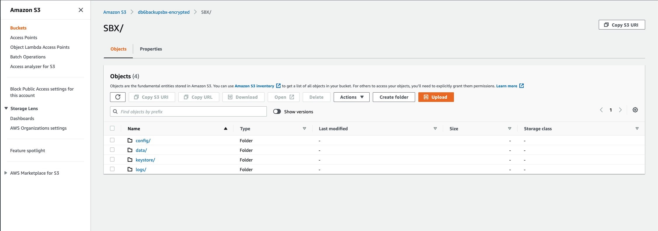
You can further customize this QuickSight analysis to produce additional visualizations, apply additional permissions, and publish it to enterprise users and groups with various levels of security.

Conclusion

Harnessing the knowledge of S3 Storage Lens metrics with other custom data enables you to discover anomalies and identify cost-efficiencies across accounts. In this post, we used serverless components to build a workflow to use this data for real-time visualization. You can use this workflow to scale up and design an enterprise-level solution with a multi-account strategy and control fine-grained access to its data using the QuickSight row-level security feature.


About the Authors

Jignesh Gohel is a Technical Account Manager at AWS. In this role, he provides advocacy and strategic technical guidance to help plan and build solutions using best practices, and proactively keep customers’ AWS environments operationally healthy. He is passionate about building modular and scalable enterprise systems on AWS using serverless technologies. Besides work, Jignesh enjoys spending time with family and friends, traveling and exploring the latest technology trends.


Suman Koduri is a Global Category Lead for Data & Analytics category in AWS Marketplace. He is focused towards business development activities to further expand the presence and success of Data & Analytics ISVs in AWS Marketplace.  In this role, he leads the scaling, and evolution of new and existing ISVs, as well as field enablement and strategic customer advisement for the same. In his spare time, he loves running half marathon’s and riding his motorcycle.

Building a serverless GIF generator with AWS Lambda: Part 1

Post Syndicated from James Beswick original https://aws.amazon.com/blogs/compute/building-a-serverless-gif-generator-with-aws-lambda-part-1/

Many video streaming services show GIF animations in the frontend when users fast forward and rewind throughout a video. This helps customers see a preview and makes the user interface more intuitive.

Generating these GIF files is a compute-intensive operation that becomes more challenging to scale when there are many videos. Over a typical 2-hour movie with GIF previews every 30 seconds, you need 240 separate GIF animations to support this functionality.

In a server-based solution, you can use a library like FFmpeg to load the underlying MP4 file and create the GIF exports. However, this may be a serial operation that slows down for longer videos or when there are many different videos to process. For a service providing thousands of videos to customers, they need a solution where the encoding process keeps pace with the number of videos.

In this two-part blog post, I show how you can use a serverless approach to create a scalable GIF generation service. I explain how you can use parallelization in AWS Lambda-based workloads to reduce processing time significantly.

The example application uses the AWS Serverless Application Model (AWS SAM), enabling you to deploy the application more easily in your own AWS account. This walkthrough creates some resources covered in the AWS Free Tier but others incur cost. To set up the example, visit the GitHub repo and follow the instructions in the README.md file.

Overview

To show the video player functionality, visit the demo front end. This loads the assets for an example video that is already processed. In the example, there are GIF animations every 30 seconds and freeze frames for every second of video. Move the slider to load the frame and GIF animation at that point in the video:

Serverless GIF generator demo

  1. The demo site defaults to an existing video. After deploying the backend application, you can test your own videos here.
  2. Move the slider to select a second in the video playback. This simulates a typical playback bar used in video application frontends.
  3. This displays the frame at the chosen second, which is a JPG file created by the backend application.
  4. The GIF animation for the selected playback point is a separate GIF file, created by the backend application.

Comparing server-based and serverless solutions

The example application uses FFmpeg, an open source application to record and process video. FFmpeg creates the GIF animations and individual frames for each second of video. You can use FFmpeg directly from a terminal or in scripts and applications. In comparing the performance, I use the AWS re:Invent 2019 keynote video, which is almost 3 hours long.

To show the server-based approach, I use a Node.js application in the GitHub repo. This loops through the video length in 30-second increments, calling FFmpeg with the necessary command line parameters:

const main = async () => {
	const length = 10323
	const inputVideo = 'test.mp4'
	const ffTmp = './output'
	const snippetSize = 30
 	const baseFilename = inputVideo.split('.')[0]

	console.time('task')
	for (let start = 0; start < length; start += snippetSize) {
		const gifName = `${baseFilename}-${start}.gif`
		const end = start + snippetSize -1

		console.log('Now creating: ', gifName)
		// Generates gif in local tmp
		await execPromise(`${ffmpegPath} -loglevel error -ss ${start} -to ${end} -y -i "${inputVideo}" -vf "fps=10,scale=240:-1:flags=lanczos,split[s0][s1];[s0]palettegen[p];[s1][p]paletteuse" -loop 0 ${ffTmp}/${gifName}`)
		await execPromise(`${ffmpegPath} -loglevel error -ss ${start} -to ${end} -i "${inputVideo}" -vf fps=1 ${ffTmp}/${baseFilename}-${start}-frame-%d.jpg`)
	}
	console.timeEnd('task')
}

Running this script from my local development machine, it takes almost 21 minutes to complete the operation and creates over 10,000 output files.

Script output

After deploying the example serverless application in the GitHub repo, I upload the video to the source Amazon S3 bucket using the AWS CLI:

aws s3 cp ./reinvent.mp4 s3://source-bucket-name --acl public-read

The completed S3 PutObject operation starts the GIF generation process. The function that processes the GIF files emits the following metrics on the Monitor tab in the Lambda console:

Lambda function metrics

  1. There are 345 invocations to process the source file into 30-second GIF animations.
  2. The average duration for each invocation is 4,311 ms. The longest is 9,021 ms.
  3. No errors occurred in processing the video.
  4. Lambda scaled up to 344 concurrent execution environments.

After approximately 10 seconds, the conversion is complete and there are over 10,000 objects in the application’s output S3 bucket:

Test results

The main reason that the task duration is reduced from nearly 21 minutes to around 10 seconds is parallelization. In the server-based approach, each 30 second GIF is processed sequentially. In the Lambda-based solution, all of the 30-second clips are generated in parallel, at around the same time:

Server-based vs Lambda-based

Solution architecture

The example application uses the following serverless architecture:

Solution architecture

  1. When the original MP4 video is put into the source S3 bucket, it invokes the first Lambda function.
  2. The Snippets Lambda function detects the length of the video. It determines the number of 30-second snippets and then puts events onto the default event bus. There is one event for each snippet.
  3. An Amazon EventBridge rule matches for events created by the first Lambda function. It invokes the second Lambda function.
  4. The Process MP4 Lambda function receives the event as a payload. It loads the original video using FFmpeg to generate the GIF and per-second frames.
  5. The resulting files are stored in the output S3 bucket.

The first Lambda function uses the following code to detect the length of the video and create events for EventBridge:

const createSnippets = async (record) => {
	// Get signed URL for source object
	const params = {
		Bucket: record.s3.bucket.name, 
		Key: record.s3.object.key, 
		Expires: 300
	}
	const url = s3.getSignedUrl('getObject', params)

	// Get length of source video
	const metadata = await ffProbe(url)
	const length = metadata.format.duration
	console.log('Length (seconds): ', length)

	// Build data array for DynamoDB
	const items = []
	const snippetSize = parseInt(process.env.SnippetSize)

	for (let start = 0; start < length; start += snippetSize) {
		items.push({
			key: record.s3.object.key,
			start,
			end: (start + snippetSize - 1),
			length,
			tsCreated: Date.now()
		})
	}
	// Send events to EventBridge
	await writeBatch(items)
}

The eventbridge.js file contains a function that sends the event array to the default bus in EventBridge. It uses the putEvents method in the EventBridge JavaScript SDK to send events in batches of 10:

const writeBatch = async (items) => {

    console.log('writeBatch items: ', items.length)

    for (let i = 0; i < items.length; i += BATCH_SIZE ) {
        const tempArray = items.slice(i, i + BATCH_SIZE)

        // Create new params array
        const paramsArray = tempArray.map((item) => {
            return {
                DetailType: 'newVideoCreated',
                Source: 'custom.gifGenerator',
                Detail: JSON.stringify ({
                    ...item
                })
            }
        })

        // Create params object for DDB DocClient
        const params = {
            Entries: paramsArray
        }

        // Write to DDB
        const result = await eventbridge.putEvents(params).promise()
        console.log('Result: ', result)
    }
}

The second Lambda function is invoked by an EventBridge rule, matching on the Source and DetailType values. Both the Lambda function and the rule are defined in the AWS SAM template:

  GifsFunction:
    Type: AWS::Serverless::Function 
    Properties:
      CodeUri: gifsFunction/
      Handler: app.handler
      Runtime: nodejs14.x
      Timeout: 30
      MemorySize: 4096
      Layers:
        - !Ref LayerARN
      Environment:
        Variables:
          GenerateFrames: !Ref GenerateFrames
          GifsBucketName: !Ref GifsBucketName
          SourceBucketName: !Ref SourceBucketName
      Policies:
        - S3ReadPolicy:
            BucketName: !Ref SourceBucketName
        - S3CrudPolicy:
            BucketName: !Ref GifsBucketName
      Events:
        Trigger:
          Type: EventBridgeRule 

          Properties:
            Pattern:        
              source:
                - custom.gifGenerator
              detail-type:
                - newVideoCreated        

This Lambda function receives an event payload specifying the start and end time for the video clip it should process. The function then calls the FFmpeg application to generate the output files. It stores these in the local /tmp storage before uploading to the output S3 bucket:
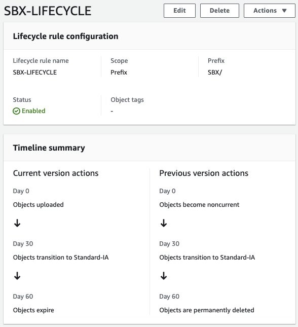
const processMP4 = async (event) => {
    // Get settings from the incoming event
    const originalMP4 = event.detail.Key 
    const start =  event.detail.start
    const end =  event.detail.end

    // Get signed URL for source object
    const params = {
        Bucket: process.env.SourceBucketName, 
        Key: originalMP4, 
        Expires
    }
    const url = s3.getSignedUrl('getObject', params)
    console.log('processMP4: ', { url, originalMP4, start, end })

    // Extract frames from MP4 (1 per second)
    console.log('Create GIF')
    const baseFilename = params.Key.split('.')[0]
    
    // Create GIF
    const gifName = `${baseFilename}-${start}.gif`
    // Generates gif in local tmp
    await execPromise(`${ffmpegPath} -loglevel error -ss ${start} -to ${end} -y -i "${url}" -vf "fps=10,scale=240:-1:flags=lanczos,split[s0][s1];[s0]palettegen[p];[s1][p]paletteuse" -loop 0 ${ffTmp}/${gifName}`)
    // Upload gif to local tmp
    // Generate frames
    if (process.env.GenerateFrames === 'true') {    
        console.log('Capturing frames')
        await execPromise(`${ffmpegPath} -loglevel error -ss ${start} -to ${end} -i "${url}" -vf fps=1 ${ffTmp}/${baseFilename}-${start}-frame-%d.jpg`)
    }

    // Upload all generated files
    await uploadFiles(`${baseFilename}/`)

    // Cleanup temp files
    await tmpCleanup()
}

Creating and using the FFmpeg Lambda layer

FFmpeg uses operating system-specific binaries that may be different on your development machine from the Lambda execution environment. The easiest way to test the code on a local machine and deploy to Lambda with the appropriate binaries is to use a Lambda layer.

As described in the example application’s README file, you can create the FFmpeg Lambda layer by deploying the ffmpeg-lambda-layer application in the AWS Serverless Application Repository. After deployment, the Layers menu in the Lambda console shows the new layer. Copy the version ARN and use this as a parameter in the AWS SAM deployment:

ffmpeg Lambda layer

On your local machine, download and install the FFmpeg binaries for your operating system. The package.json file for the Lambda functions uses two npm installer packages to help ensure the Node.js code uses the correct binaries when tested locally:

{
  "name": "gifs",
  "version": "1.0.0",
  "description": "",
  "main": "index.js",
  "scripts": {
    "test": "echo \"Error: no test specified\" && exit 1"
  },
  "keywords": [],
  "author": "James Beswick",
  "license": "MIT-0",
  "dependencies": {
  },
  "devDependencies": {
    "@ffmpeg-installer/ffmpeg": "^1.0.20",
    "@ffprobe-installer/ffprobe": "^1.1.0",
    "aws-sdk": "^2.927.0"
  }
}

Any npm packages specified in the devDependencies section of package.json are not deployed to Lambda by AWS SAM. As a result, local testing uses local ffmpeg binaries and Lambda uses the previously deployed Lambda layer. This approach also helps to reduce the size of deployment uploads and can help make the testing and deployment cycle faster in development.

Using FFmpeg from a Lambda function

FFmpeg is an application that’s generally used via a terminal. It takes command line parameters as options to determine input files, output locations, and the type of processing needed. To use terminal commands from Lambda, both functions use the asynchronous child_process module in Node.js. The execPromise function wraps this module in a Promise so the main function can use async/await syntax:

const { exec } = require('child_process')

const execPromise = async (command) => {
    console.log(command)
    return new Promise((resolve, reject) => {
        const ls = exec(command, function (error, stdout, stderr) {
          if (error) {
            console.error('Error: ', error)
            reject(error)
          }
          if (stdout) console.log('stdout: ', stdout)
          if (stderr) console.error('stderr: ' ,stderr)
        })
        
        ls.on('exit', (code) => {
          console.log('execPromise finished with code ', code)
          resolve()
        })
    })
}

As a result, you can then call FFmpeg by constructing a command line with options parameters and passing to execPromise:

await execPromise(`${ffmpegPath} -loglevel error -ss ${start} -to ${end} -i "${url}" -vf fps=1 ${ffTmp}/${baseFilename}-${start}-frame-%d.jpg`)

Alternatively, you can also use the fluent-ffmpeg npm library, which exposes the command line options as methods. The example application uses this in the ffmpeg-promisify.js file:

const ffmpeg = require("fluent-ffmpeg")
   ffmpeg(source)
      .noAudio()
      .size(`${IMG_WIDTH}x${IMG_HEIGHT}`)
      .setStartTime(startFormatted)
      .setDuration(snippetSize - 1)
      .output(outputFile)
      .on("end", async (err) => {
        // do work
      })
      .on("error", function (err) {
        console.error('FFMPEG error: ', err)
      })
      .run()

Deploying the application

In the GitHub repository, there are detailed deployment instructions for the example application. The repo contains separate directories for the demo frontend application, server-based script, and the two versions of backend service.

After deployment, you can test the application by uploading an MP4 video to the source S3 bucket. The output GIF and JPG files are written to the application’s destination S3 bucket. The files from each MP4 file are grouped in a folder in the bucket:

S3 bucket contents

Frontend application

The frontend application allows you to visualize the outputs of the backend application. There is also a hosted version of this application. This accepts custom parameters to load graphics resources from S3 buckets in your AWS account. Alternatively, you can run the frontend application locally.

To launch the frontend application:

  1. After cloning the repo, change to the frontend directory.
  2. Run npm install to install Vue.js and all the required npm modules from package.json.
  3. Run npm run serve to start the development server. After building the modules in the project, the terminal shows the local URL where the application is running:
    Terminal output
  4. Open a web browser and navigate to http://localhost:8080 to see the application:
    Localhost browser application

Conclusion

In part 1 of this blog post, I explain how a GIF generation service can support a front-end application for video streaming. I compare the performance of a server-based and serverless approach and show how parallelization can significantly improve processing time. I walk through the solution architecture used in the example application and show how you can use FFmpeg in Lambda functions.

Part 2 covers advanced topics around this implementation. It explains the scaling behavior and considers alternative approaches, and looks at the cost of using this service.

For more serverless learning resources, visit Serverless Land.