Tag Archives: Technical How-to

Use Amazon ECS Fargate Spot with CircleCI to deploy and manage applications in a cost-effective way

Post Syndicated from Pritam Pal original https://aws.amazon.com/blogs/devops/deploy-apps-cost-effective-way-with-ecs-fargate-spot-and-circleci/

This post is written by Pritam Pal, Sr EC2 Spot Specialist SA & Dan Kelly, Sr EC2 Spot GTM Specialist

Customers are using Amazon Web Services (AWS) to build CI/CD pipelines and follow DevOps best practices in order to deliver products rapidly and reliably. AWS services simplify infrastructure provisioning and management, application code deployment, software release processes automation, and application and infrastructure performance monitoring. Builders are taking advantage of low-cost, scalable compute with Amazon EC2 Spot Instances, as well as AWS Fargate Spot to build, deploy, and manage microservices or container-based workloads at a discounted price.

Amazon EC2 Spot Instances let you take advantage of unused Amazon Elastic Compute Cloud (Amazon EC2) capacity at steep discounts as compared to on-demand pricing. Fargate Spot is an AWS Fargate capability that can run interruption-tolerant Amazon Elastic Container Service (Amazon ECS) tasks at up to a 70% discount off the Fargate price. Since tasks can still be interrupted, only fault tolerant applications are suitable for Fargate Spot. However, for flexible workloads that can be interrupted, this feature enables significant cost savings over on-demand pricing.

CircleCI provides continuous integration and delivery for any platform, as well as your own infrastructure. CircleCI can automatically trigger low-cost, serverless tasks with AWS Fargate Spot in Amazon ECS. Moreover, CircleCI Orbs are reusable packages of CircleCI configuration that help automate repeated processes, accelerate project setup, and ease third-party tool integration. Currently, over 1,100 organizations are utilizing the CircleCI Amazon ECS Orb to power/run 250,000+ jobs per month.

Customers are utilizing Fargate Spot for a wide variety of workloads, such as Monte Carlo simulations and genomic processing. In this blog, I utilize a python code with the Tensorflow library that can run as a container image in order to train a simple linear model. It runs the training steps in a loop on a data batch and periodically writes checkpoints to S3. If there is a Fargate Spot interruption, then it restores the checkpoint from S3 (when a new Fargate Instance occurs) and continues training. We will deploy this on AWS ECS Fargate Spot for low-cost, serverless task deployment utilizing CircleCI.

Concepts

Before looking at the solution, let’s revisit some of the concepts we’ll be using.

Capacity Providers: Capacity providers let you manage computing capacity for Amazon ECS containers. This allows the application to define its requirements for how it utilizes the capacity. With capacity providers, you can define flexible rules for how containerized workloads run on different compute capacity types and manage the capacity scaling. Furthermore, capacity providers improve the availability, scalability, and cost of running tasks and services on Amazon ECS. In order to run tasks, the default capacity provider strategy will be utilized, or an alternative strategy can be specified if required.

AWS Fargate and AWS Fargate Spot capacity providers don’t need to be created. They are available to all accounts and only need to be associated with a cluster for utilization. When a new cluster is created via the Amazon ECS console, along with the Networking-only cluster template, the FARGATE and FARGATE_SPOT capacity providers are automatically associated with the new cluster.

CircleCI Orbs: Orbs are reusable CircleCI configuration packages that help automate repeated processes, accelerate project setup, and ease third-party tool integration. Orbs can be found in the developer hub on the CircleCI orb registry. Each orb listing has usage examples that can be referenced. Moreover, each orb includes a library of documented components that can be utilized within your config for more advanced purposes. Since the 2.0.0 release, the AWS ECS Orb supports the capacity provider strategy parameter for running tasks allowing you to efficiently run any ECS task against your new or existing clusters via Fargate Spot capacity providers.

Solution overview

Fargate Spot helps cost-optimize services that can handle interruptions like Containerized workloads, CI/CD, or Web services behind a load balancer. When Fargate Spot needs to interrupt a running task, it sends a SIGTERM signal. It is best practice to build applications capable of responding to the signal and shut down gracefully.

This walkthrough will utilize a capacity provider strategy leveraging Fargate and Fargate Spot, which mitigates risk if multiple Fargate Spot tasks get terminated simultaneously. If you’re unfamiliar with Fargate Spot, capacity providers, or capacity provider strategies, read our previous blog about Fargate Spot best practices here.

Prerequisites

Our walkthrough will utilize the following services:

  • GitHub as a code repository
  • AWS Fargate/Fargate Spot for running your containers as ECS tasks
  • CircleCI for demonstrating a CI/CD pipeline. We will utilize CircleCI Cloud Free version, which allows 2,500 free credits/week and can run 1 job at a time.

We will run a Job with CircleCI ECS Orb in order to deploy 4 ECS Tasks on Fargate and Fargate Spot. You should have the following prerequisites:

  1. An AWS account
  2. A GitHub account

Walkthrough

Step 1: Create AWS Keys for Circle CI to utilize.

Head to AWS IAM console, create a new user, i.e., circleci, and select only the Programmatic access checkbox. On the set permission page, select Attach existing policies directly. For the sake of simplicity, we added a managed policy AmazonECS_FullAccess to this user. However, for production workloads, employ a further least-privilege access model. Download the access key file, which will be utilized to connect to CircleCI in the next steps.

Step 2: Create an ECS Cluster, Task definition, and ECS Service

2.1 Open the Amazon ECS console

2.2 From the navigation bar, select the Region to use

2.3 In the navigation pane, choose Clusters

2.4 On the Clusters page, choose Create Cluster

2.5 Create a Networking only Cluster ( Powered by AWS Fargate)

Amazon ECS Create Cluster

This option lets you launch a cluster in your existing VPC to utilize for Fargate tasks. The FARGATE and FARGATE_SPOT capacity providers are automatically associated with the cluster.

2.6 Click on Update Cluster to define a default capacity provider strategy for the cluster, then add FARGATE and FARGATE_SPOT capacity providers each with a weight of 1. This ensures Tasks are divided equally among Capacity providers. Define other ratios for splitting your tasks between Fargate and Fargate Spot tasks, i.e., 1:1, 1:2, or 3:1.

ECS Update Cluster Capacity Providers

2.7 Here we will create a Task Definition by using the Fargate launch type, give it a name, and specify the task Memory and CPU needed to run the task. Feel free to utilize any Fargate task definition. You can use your own code, add the code in a container, or host the container in Docker hub or Amazon ECR. Provide a name and image URI that we copied in the previous step and specify the port mappings. Click Add and then click Create.

We are also showing an example of a python code using the Tensorflow library that can run as a container image in order to train a simple linear model. It runs the training steps in a loop on a batch of data, and it periodically writes checkpoints to S3. Please find the complete code here. Utilize a Dockerfile to create a container from the code.

Sample Docker file to create a container image from the code mentioned above.

FROM ubuntu:18.04
WORKDIR /app
COPY . /app
RUN pip install -r requirements.txt EXPOSE 5000 CMD python tensorflow_checkpoint.py

Below is the Code Snippet we are using for Tensorflow to Train and Checkpoint a Training Job.


def train_and_checkpoint(net, manager):
  ckpt.restore(manager.latest_checkpoint).expect_partial()
  if manager.latest_checkpoint:
    print("Restored from {}".format(manager.latest_checkpoint))
  else:
    print("Initializing from scratch.")
  for _ in range(5000):
    example = next(iterator)
    loss = train_step(net, example, opt)
    ckpt.step.assign_add(1)
    if int(ckpt.step) % 10 == 0:
        save_path = manager.save()
        list_of_files = glob.glob('tf_ckpts/*.index')
        latest_file = max(list_of_files, key=os.path.getctime)
        upload_file(latest_file, 'pythontfckpt', object_name=None)
        list_of_files = glob.glob('tf_ckpts/*.data*')
        latest_file = max(list_of_files, key=os.path.getctime)
        upload_file(latest_file, 'pythontfckpt', object_name=None)
        upload_file('tf_ckpts/checkpoint', 'pythontfckpt', object_name=None)

2.8 Next, we will create an ECS Service, which will be used to fetch Cluster information while running the job from CircleCI. In the ECS console, navigate to your Cluster, From Services tab, then click create. Create an ECS service by choosing Cluster default strategy from the Capacity provider strategy dropdown. For the Task Definition field, choose webapp-fargate-task, which is the one we created earlier, enter a service name, set the number of tasks to zero at this point, and then leave everything else as default. Click Next step, select an existing VPC and two or more Subnets, keep everything else default, and create the service.

Step 3: GitHub and CircleCI Configuration

Create a GitHub repository, i.e., circleci-fargate-spot, and then create a .circleci folder and a config file config.yml. If you’re unfamiliar with GitHub or adding a repository, check the user guide here.

For this project, the config.yml file contains the following lines of code that configure and run your deployments.

version: '2.1'
orbs:
  aws-ecs: circleci/[email protected]
  aws-cli: circleci/[email protected]
  orb-tools: circleci/[email protected]
  shellcheck: circleci/[email protected]
  jq: circleci/[email protected]

jobs:  

  test-fargatespot:
      docker:
        - image: cimg/base:stable
      steps:
        - aws-cli/setup
        - jq/install
        - run:
            name: Get cluster info
            command: |
              SERVICES_OBJ=$(aws ecs describe-services --cluster "${ECS_CLUSTER_NAME}" --services "${ECS_SERVICE_NAME}")
              VPC_CONF_OBJ=$(echo $SERVICES_OBJ | jq '.services[].networkConfiguration.awsvpcConfiguration')
              SUBNET_ONE=$(echo "$VPC_CONF_OBJ" |  jq '.subnets[0]')
              SUBNET_TWO=$(echo "$VPC_CONF_OBJ" |  jq '.subnets[1]')
              SECURITY_GROUP_IDS=$(echo "$VPC_CONF_OBJ" |  jq '.securityGroups[0]')
              CLUSTER_NAME=$(echo "$SERVICES_OBJ" |  jq '.services[].clusterArn')
              echo "export SUBNET_ONE=$SUBNET_ONE" >> $BASH_ENV
              echo "export SUBNET_TWO=$SUBNET_TWO" >> $BASH_ENV
              echo "export SECURITY_GROUP_IDS=$SECURITY_GROUP_IDS" >> $BASH_ENV=$SECURITY_GROUP_IDS=$SECURITY_GROUP_IDS" >> $BASH_ENV" >> $BASH_ENV
              echo "export CLUSTER_NAME=$CLUSTER_NAME" >> $BASH_ENV
        - run:
            name: Associate cluster
            command: |
              aws ecs put-cluster-capacity-providers \
                --cluster "${ECS_CLUSTER_NAME}" \
                --capacity-providers FARGATE FARGATE_SPOT  \
                --default-capacity-provider-strategy capacityProvider=FARGATE,weight=1 capacityProvider=FARGATE_SPOT,weight=1\                --region ${AWS_DEFAULT_REGION}
        - aws-ecs/run-task:
              cluster: $CLUSTER_NAME
              capacity-provider-strategy: capacityProvider=FARGATE,weight=1 capacityProvider=FARGATE_SPOT,weight=1
              launch-type: ""
              task-definition: webapp-fargate-task
              subnet-ids: '$SUBNET_ONE, $SUBNET_TWO'
              security-group-ids: $SECURITY_GROUP_IDS
              assign-public-ip : ENABLED
              count: 4

workflows:
  run-task:
    jobs:
      - test-fargatespot

Now, Create a CircleCI account. Choose Login with GitHub. Once you’re logged in from the CircleCI dashboard, click Add Project and add the project circleci-fargate-spot from the list shown.

When working with CircleCI Orbs, you will need the config.yml file and environment variables under Project Settings.

The config file utilizes CircleCI version 2.1 and various Orbs, i.e., AWS-ECS, AWS-CLI, and JQ.  We will use a job test-fargatespot, which uses a Docker image, and we will setup the environment. In config.yml we are using the jq tool to parse JSON and fetch the ECS cluster information like VPC config, Subnets, and Security Groups needed to run an ECS task. As we are utilizing the capacity-provider-strategy, we will set the launch type parameter to an empty string.

In order to run a task, we will demonstrate how to override the default Capacity Provider strategy with Fargate & Fargate Spot, both with a weight of 1, and to divide tasks equally among Fargate & Fargate Spot. In our example, we are running 4 tasks, so 2 should run on Fargate and 2 on Fargate Spot.

Parameters like ECS_SERVICE_NAME, ECS_CLUSTER_NAME and other AWS access specific details are added securely under Project Settings and can be utilized by other jobs running within the project.

Add the following environment variables under Project Settings

    • AWS_ACCESS_KEY_ID – From Step 1
    • AWS_SECRET_ACCESS_KEY – From Step 1
    • AWS_DEFAULT_REGION – i.e. : – us-west-2
    • ECS_CLUSTER_NAME – From Step 2
    • ECS_SERVICE_NAME – From Step 2
    • SECURITY_GROUP_IDS – Security Group that will be used to run the task

Circle CI Environment Variables


Step 4: Run Job

Now in the CircleCI console, navigate to your project, choose the branch, and click Edit Config to verify that config.xml is correctly populated. Check for the ribbon at the bottom. A green ribbon means that the config file is valid and ready to run. Click Commit & Run from the top-right menu.

Click build Status to check its progress as it runs.

CircleCI Project Dashboard


A successful build should look like the one below. Expand each section to see the output.


CircleCI Job Configuration

Return to the ECS console, go to the Tasks Tab, and check that 4 new tasks are running. Click each task for the Capacity provider details. Two tasks should have run with FARGATE_SPOT as a Capacity provider, and two should have run with FARGATE.

Congratulations!

You have successfully deployed ECS tasks utilizing CircleCI on AWS Fargate and Fargate Spot. If you have used any sample web applications, then please use the public IP address to see the page. If you have used the sample code that we provided, then you should see Tensorflow training jobs running on Fargate instances. If there is a Fargate Spot interruption, then it restores the checkpoint from S3 when a new Fargate Instance comes up and continues training.

Cleaning up

In order to avoid incurring future charges, delete the resources utilized in the walkthrough. Go to the ECS console and Task tab.

  • Delete any running Tasks.
  • Delete ECS cluster.
  • Delete the circleci user from IAM console.

Cost analysis in Cost Explorer

In order to demonstrate a cost breakdown between the tasks running on Fargate and Fargate Spot, we left the tasks running for a day. Then, we utilized Cost Explorer with the following filters and groups in order discover the savings by running Fargate Spot.

Apply a filter on Service for ECS on the right-side filter, set Group by to Usage Type, and change the time period to the specific day.

Cost analysis in Cost Explorer

The cost breakdown demonstrates how Fargate Spot usage (indicated by “SpotUsage”) was significantly less expensive than non-Spot Fargate usage. Current Fargate Spot Pricing can be found here.

Conclusion

In this blog post, we have demonstrated how to utilize CircleCI to deploy and manage ECS tasks and run applications in a cost-effective serverless approach by using Fargate Spot.

Author bio

Pritam is a Sr. Specialist Solutions Architect on the EC2 Spot team. For the last 15 years, he evangelized DevOps and Cloud adoption across industries and verticals. He likes to deep dive and find solutions to everyday problems.
Dan is a Sr. Spot GTM Specialist on the EC2 Spot Team. He works closely with Amazon Partners to ensure that their customers can optimize and modernize their compute with EC2 Spot.


Sending mobile push notifications and managing device tokens with serverless applications

Post Syndicated from James Beswick original https://aws.amazon.com/blogs/compute/sending-mobile-push-notifications-and-managing-device-tokens-with-serverless-application/

This post is written by Rafa Xu, Cloud Architect, Serverless and Joely Huang, Cloud Architect, Serverless.

Amazon Simple Notification Service (SNS) is a fast, flexible, fully managed push messaging service in the cloud. SNS can send mobile push notifications directly to applications on mobile devices such as message alerts and badge updates. SNS sends push notifications to a mobile endpoint created by supplying a mobile token and platform application.

When publishing mobile push notifications, a device token is used to generate an endpoint. This identifies where the push notification is sent (target destination). To push notifications successfully, the token must be up to date and the endpoint must be validated and enabled.

A common challenge when pushing notifications is keeping the token up to date. Tokens can automatically change due to reasons such as mobile operating system (OS) updates and application store updates.

This post provides a serverless solution to this challenge. It also provides a way to publish push notifications to specific end users by maintaining a mapping between users, endpoints, and tokens.

Overview

To publish mobile push notifications using SNS, generate an SNS endpoint to use as a destination target for the push notification. To create the endpoint, you must supply:

  1. A mobile application token: The mobile operating system (OS) issues the token to the application. It is a unique identifier for the application and mobile device pair.
  2. Platform Application Amazon Resource Name (ARN): SNS provides this ARN when you create a platform application object. The platform application object requires a valid set of credentials issued by the mobile platform, which you provide to SNS.

Once the endpoint is generated, you can store and reuse it again. This prevents the application from creating endpoints indefinitely, which could exhaust the SNS endpoint limit.

To reuse the endpoints and successfully push notifications, there are a number of challenges:

  • Mobile application tokens can change due to a number of reasons, such as application updates. As a result, the publisher must update the platform endpoint to ensure it uses an up-to-date token.
  • Mobile application tokens can become invalid. When this happens, messages won’t be published, and SNS disables the endpoint with the invalid token. To resolve this, publishers must retrieve a valid token and re-enable the platform endpoint
  • Mobile applications can have many users, each user could have multiple devices, or one device could have multiple users. To send a push notification to a specific user, a mapping between the user, device, and platform endpoints should be maintained.

For more information on best practices for managing mobile tokens, refer to this post.

Follow along the blog post to learn how to implement a serverless workflow for managing and maintaining valid endpoints and user mappings.

Solution overview

The solution uses the following AWS services:

  • Amazon API Gateway: Provides a token registration endpoint URL used by the mobile application. Once called, it invokes an AWS Lambda function via the Lambda integration.
  • Amazon SNS: Generates and maintains the target endpoint and manages platform application objects.
  • Amazon DynamoDB: Serverless database for storing endpoints that also maintains a mapping between the user, endpoint, and mobile operating system.
  • AWS Lambda: Retrieves endpoints from DynamoDB, validates and generates endpoints, and publishes notifications by making requests to SNS.

The following diagram represents a simplified interaction flow between the AWS services:

Solution architecture

To register the token, the mobile app invokes the registration token endpoint URL generated by Amazon API Gateway. The token registration happens every time a user logs in or opens the application. This ensures that the token and endpoints are always valid during the application usage.

The mobile application passes the token, user, and mobileOS as parameters to API Gateway, which forwards the request to the Lambda function.

The Lambda function validates the token and endpoint for the user by making API calls to DynamoDB and SNS:

  1. The Lambda function checks DynamoDB to see if the endpoint has been previously created.
    1. If the endpoint does not exist, it creates a platform endpoint via SNS.
  2. Obtain the endpoint attributes from SNS:
    1. Check the “enabled” endpoint attribute and set to “true” to enable the platform endpoint, if necessary.
    2. Validate the “token” endpoint attribute with the token provided in the API Gateway request. If it does not match, update the “token” attribute.
    3. Send a request to SNS to update the endpoint attributes.
  3. If a new endpoint is created, update DynamoDB with the new endpoint.
  4. Return a successful response to API Gateway.

Deploying the AWS Serverless Application Model (AWS SAM) template

Use the AWS SAM template to deploy the infrastructure for this workflow. Before deploying the template, first create a platform application in SNS.

  1. Navigate to the SNS console. Select Push Notifications on the left-hand menu to create a platform application:
    Mobile push notifications
  2. This shows the creation of a platform application for iOS applications:
    Create platform application
  3. To install AWS SAM, visit the installation page.
  4. To deploy the AWS SAM template, navigate to the directory where the template is located. Run the commands in the terminal:
    git clone https://github.com/aws-samples/serverless-mobile-push-notification
    cd serverless-mobile-push-notification
    sam build
    sam deploy --guided

Lambda function code snippets

The following section explains code from the Lambda function for the workflow.

Create the platform endpoint

If the endpoint exists, store it as a variable in the code. If the platform endpoint does not exist in the DynamoDB database, create a new endpoint:

        need_update_ddb = False
        response = table.get_item(Key={'username': username, 'appos': appos})
        if 'Item' not in response:
            # create endpoint
            response = snsClient.create_platform_endpoint(
                PlatformApplicationArn=SUPPORTED_PLATFORM[appos],
                Token=token,
            )
            devicePushEndpoint = response['EndpointArn']
            need_update_ddb = True
        else:
            # update the endpoint
            devicePushEndpoint = response['Item']['endpoint']

Check and update endpoint attributes

Check that the token attribute for the platform endpoint matches the token received from the mobile application through the request. This also checks for the endpoint “enabled” attribute and re-enables the endpoint if necessary:

response = snsClient.get_endpoint_attributes(
                EndpointArn=devicePushEndpoint
            )
            endpointAttributes = response['Attributes']

            previousToken = endpointAttributes['Token']
            previousStatus = endpointAttributes['Enabled']
            if previousStatus.lower() != 'true' or previousToken != token:
                snsClient.set_endpoint_attributes(
                    EndpointArn=devicePushEndpoint,
                    Attributes={
                        'Token': token,
                        'Enabled': 'true'
                    }
                )

Update the DynamoDB table with the newly generated endpoint

If a platform endpoint is newly created, meaning there is no item in the DynamoDB table, create a new item in the table:

        if need_update_ddb:
            table.update_item(
                Key={
                    'username': username,
                    'appos': appos
                },
                UpdateExpression="set endpoint=:e",
                ExpressionAttributeValues={
                    ':e': devicePushEndpoint
                },
                ReturnValues="UPDATED_NEW"
            )

As best practice, the code cleans up the table, in case there are multiple entries for the same endpoint mapped to different users. This can happen when the mobile application is used by multiple users on the same device. When one user logs out and a different user logs in, this creates a new entry in the DynamoDB table to map the endpoint with the new user.

As a result, you must remove the entry that maps the same endpoint to the previously logged in user. This way, you only keep the endpoint that matches the user provided by the mobile application through the request.

result = table.query(
    # Add the name of the index you want to use in your query.
        IndexName="endpoint-index",
        KeyConditionExpression=Key('endpoint').eq(devicePushEndpoint),
    )
    for item in result['Items']:
        if item['username'] != username and item['appos'] == appos:
            print(f"deleting orphan item: username {username}, os {appos}".format(username=item['username'], appos=appos))
            table.delete_item(
                Key={
                    'username': item['username'],
                    'appos': appos
                },
            )

Conclusion

This blog shows how to deploy a serverless solution for validating and managing SNS platform endpoints and tokens. To publish push notifications successfully, use SNS to check the endpoint attribute and ensure it is mapped to the correct token and the endpoint is enabled.

This approach uses DynamoDB to store the device token and platform endpoints for each user. This allows you to send push notifications to specific users, retrieve, and reuse previously created endpoints. You create a Lambda function to facilitate the workflow, including validating the DynamoDB item for storing an enabled and up-to-date token.

Visit this link to learn more about Amazon SNS mobile push notifications: http://docs.aws.amazon.com/sns/latest/dg/SNSMobilePush.html

For more serverless learning resources, visit Serverless Land.

Field Notes: Deploy and Visualize ROS Bag Data on AWS using rviz and Webviz for Autonomous Driving

Post Syndicated from Aubrey Oosthuizen original https://aws.amazon.com/blogs/architecture/field-notes-deploy-and-visualize-ros-bag-data-on-aws-using-rviz-and-webviz-for-autonomous-driving/

In the automotive industry, ROS bag files are frequently used to capture drive data from test vehicles configured with cameras, LIDAR, GPS, and other input devices. The data for each device is stored as a topic in the ROS bag file. Developers and engineers need to visualize and inspect the contents of ROS bag files to identify issues or replay the drive data.

There are a couple of challenges to be addressed by migrating the visualization workflow into Amazon Web Services (AWS):

  • Search, identify, and stream scenarios for ADAS engineers. Visualization tool should be ready instantly, load the data for a certain scenario over a search API, and show the first result through data streaming, to provide a good user experience.
  • Native integration with the tool chain. Many customers implement the Data Catalog, data storage, and search API in AWS native services. This visualization tool should be integrated into such a tool chain directly.

Overview of solutions

This blog post describes three solutions on how to deploy and visualize ROS bag data on AWS by using two popular visualization tools:

  • rviz is the standard open-source visualization tool used by the ROS community and has a large set of tools and plugin support.
  • Webviz is an open-source tool created by Cruise that provides modular and configurable browser-based visualization.

In the autonomous driving data lake reference architecture, both visualization tools are covered in the step 10: Provide an advanced analytics and visualization toolchain including search function for particular scenarios using AWS AppSync, Amazon QuickSight (KPI reporting and monitoring), and Webviz, rviz, or other tooling for visualization.

Prerequisites

Solution 1 – Visualize ROS bag files using rviz on AWS RoboMaker virtual desktops

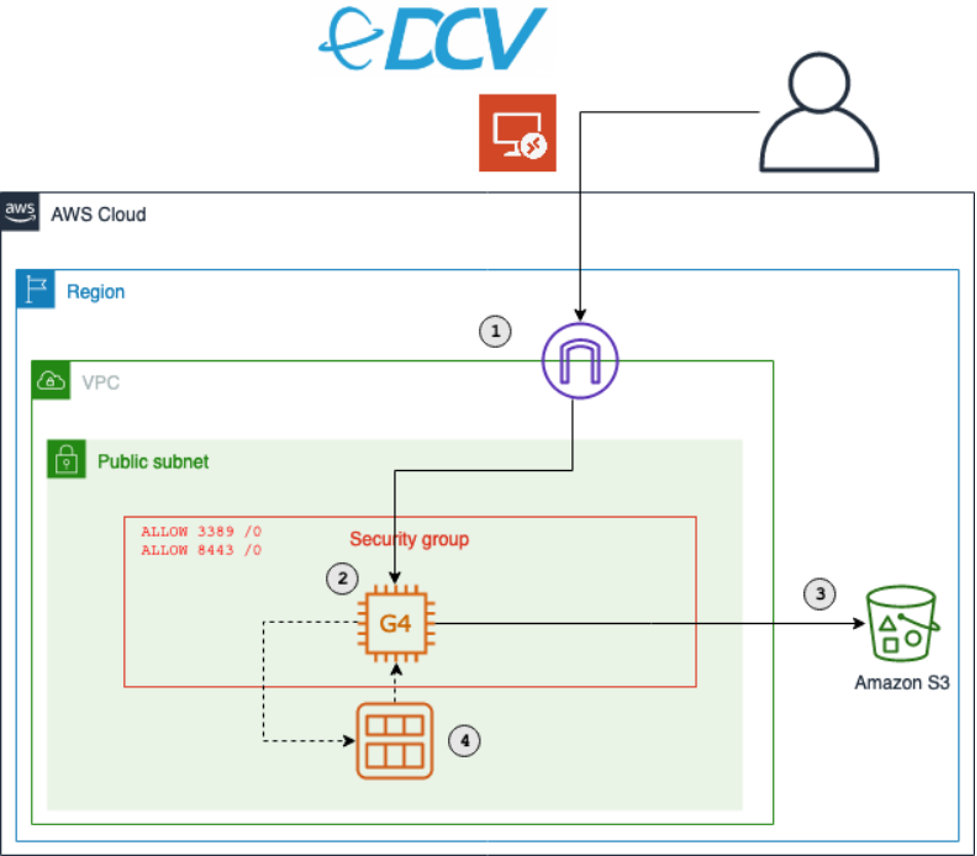
AWS RoboMaker provides simulation and testing infrastructure for robotics as a managed service. This includes out of the box support for virtual desktops with ROS tooling preconfigured and installed. When you launch a virtual desktop, AWS RoboMaker launches the NICE DCV web browser client. This client provides access to your AWS Cloud9 desktop and streaming applications.

Launch rviz on AWS RoboMaker virtual desktop

Follow the guide on creating a new development environment to provision a new integrated development environment (IDE) and open it. After your AWS Cloud9 IDE is open, you can launch a new virtual desktop by pressing the Virtual Desktop button at the top center of the IDE, and selecting Launch Virtual Desktop. This might take a couple of seconds to open in a new browser tab.

After your virtual desktop is loaded, you can run rviz by opening the terminal and running the following commands:

$ source /opt/ros/melodic/setup.bash
$ roscore &
$ rosrun rviz rviz

Solution 2 – Visualize ROS bag files using rviz on EC2 and TigerVNC

Note: We strongly recommend using the AWS RoboMaker managed solution for provisioning virtual desktops for your visualization needs. In cases where this is not possible due to different Linux distributions or versions, this solution allows an alternative method for setting up a virtual desktop on EC2.

In this solution (source code) we use AWS Cloud Development Kit (AWS CDK) to deploy a new Ubuntu 18.04 AMI EC2 instance to your AWS account and preconfigure it with rviz, TigerVNC, and Ubuntu Desktop.


Figure 1. Architecture for solution 2 (visualize ROS bag files using rviz on EC2 and TigerVNC)

Open a shell terminal that has your AWS CLI configured. Run the following commands to clone the code and install the corresponding nodejs dependencies.

$ git clone https://github.com/aws-samples/aws-autonomous-driving-data-lake-ros-bag-visualization-using-rviz.git rviz-infra
$ cd rviz-infra
$ npm install

Note: Review the README to understand the project structure and commands.

Next, configure your project-specific settings, like your AWS Account, Region, VNC password, VPC to deploy the Amazon EC2 machine into, and EC2 instance type by running the bootstrap script:

$ npm run project-bootstrap

You will be prompted for various inputs to bootstrap the project, including the VNC password to use. Most of these input values will be stored into your cdk.json file, and the VNC password will be stored in the AWS Systems Manager Parameter Store, a capability of AWS Systems Manager.

Run the following command to deploy your stack into your AWS account.

$ cdk deploy

After the stack has been deployed, and the EC2 instance provisioned, its user-data script will initiate and install TigerVNC and the required ROS tooling.

To see the progress, let’s connect to the instance using SSH and then tail the bootstrapping log.

$ ./ssm.sh ssh
$ sudo su ubuntu
$ tail -f /var/log/cloud-init-output.log

It takes approximately 15 minutes for the user-data bootstrapping script to finish. When it finishes, you will see the message “rviz-setup bootstrapping completed. You can now log in via VNC”.

Open a new shell terminal in the project root and start a port forwarding session using SSM through the ssm helper script:

$ ./ssm.sh vnc

After you see the waiting for connections output, you can open your VNC viewer and connect to localhost:5901.

When prompted for a password, enter the one you used when previously running the bootstrapping script.

You now have access to your Ubuntu Desktop environment.

Running rviz

If you opted to install sample data, the Ford AV Sample Data has been downloaded and installed on the EC2 instance already. To visualize it in rviz, a few helper scripts have been created and can be run by opening a new terminal and initiating the following commands:

$ cd /home/ubuntu/catkin_ws
$ ./0-run-all.sh

This helper script will open and run rviz on the Ford sample data.

Figure 2. Ford AV Dataset visualized with rviz on Ubuntu Desktop

You should now be able to use this server to run and visualize your ROS bag files using rviz.

Solution 3 – Visualize ROS bag files using Webviz on Amazon Elastic Container Service (Amazon ECS)

The third solution (source code) uses AWS CDK to deploy Webviz as a container running on AWS Fargate, fronted by an Application Load Balancer (ALB). In addition, the Infrastructure as Code (IaC) can either create a new Amazon S3 bucket or import an existing one. The S3 bucket would have its cross-origin resource sharing (CORS) rules updated to allow streaming bag files from your ALB domain.

The bucket and ROS bag files won’t need to be made public since we will use presigned Amazon S3 URLs for authorizing the streaming of the files.

Finally, the AWS CDK code deploys an AWS Lambda function that can be invoked to generate a properly formatted Webviz streaming URL that contains the HTTP encoded and presigned URL for streaming your bag files directly in the browser.

Figure 3. Architecture for solution 3 (visualize ROS bag files using Webviz on Amazon ECS)

To clone the repository and install its dependencies.

$ git clone https://github.com/aws-samples/aws-autonomous-driving-data-lake-ros-bag-visualization-using-webviz.git webviz-infra
$ cd webviz-infra
$ npm install

Note: Review the project README to understand the different files, project structures, and commands.

Next, modify the cdk.json to specify your specific project configurations (for example, region, bucket name, and whether you wish to import an existing bucket or create a new one).

{
  "context": {
    ....
    "bucketName": "<bucket_name>", // [required] Name of bucket to use or create
    "bucketExists": true, // [required] Should create or update existing bucket
    "generateUrlFunctionName": "generate_ros_streaming_url", // [required] Name of lambda function
    "scenarioDB": { // [optional] Configuration of SceneDescription table
      "partitionKey": "bag_file",
      "sortKey": "scene_id",
      "region": "eu-west-1",
      "tableName": "SceneDescriptions"
    }
  }
}

To deploy the CDK stack into your AWS account run the following command.

$ cdk deploy

You can now access your Webviz instance by opening the URL value for the webvizserviceServiceURL output from the previous deploy command.

Figure 4. Example showing Webviz being served by our ALB

Custom layouts for Webviz can be imported through json configs. The solution contains an example config in the project root. This custom layout contains the topic configurations and window layouts specific to our ROS bag format and should be modified according to your ROS bag topics.

  1. Select Config → Import/Export Layout
  2. Copy and paste the contents of layout.json

Figure 5. Configuring custom layout for Webviz

Next, you need some ROS bag files to stream into your S3 bucket. If you configured AWS CDK to use an existing bucket, and the bucket already contains some ROS bag files, then you can skip the next step.

Upload ROS bag files

You can use the AWS CLI to copy a local bag file to the specified S3 bucket using the aws s3 cp command. You can also copy files between S3 buckets with the aws s3 cp command.

Generate streaming URL with helper script

The code repository contains a Python helper script in the project root to invoke your deployed Lambda function generate_ros_streaming_url locally with the correct payload.

To run the helper script, run the following command in your terminal:

$ python get_url.py \
--bucket-name <bucket_name> \
--key <ros_bag_key>

Response format: http://webviz-lb-<account>.<region>.elb.amazonaws.com?remote-bag-url=<presigned-url>

The response URL can be opened directly in your browser to visualize your targeted ROS bag file.

Generate a streaming URL through Lambda function in the AWS Console

You can generate a streaming URL by invoking your Lambda function generate_ros_streaming_url with the following example payload in the AWS console.

{
"key": "<ros_bag_key>",
"bucket": "<bucket_name>",
"seek_to": "<ros_timestamp>"
}

The seek_to value informs the Lambda function to add a parameter to jump to the specified ROS timestamp when generating the streaming URL.

Example output:

{
"statusCode": 200,
"body":
"{\"url\": \"http://webviz-lb-<domain>.<region>.elb.amazonaws.com?remote-bag-url=<PRESIGNED_ENCODED_URL>&seek-to=<ros_timestamp>\"}"
}

This body output URL can be opened in your browser to start visualizing your bag files directly.

By using a Lambda function to generate the streaming URL, you have the flexibility to integrate it with other user interfaces or dashboards. For example, if you use Amazon QuickSight to visualize different detected scenarios, you can define a customer action to invoke the Lambda function through API Gateway to get a streaming URL for the target scenario.

Similarly, custom web applications can be used to visualize the scenes and their corresponding ROS bag files stored in a metadata store. Invoke the Lambda function from your web server to generate and return a visualization URL that can be use by the web application.

Using the streaming URL

Open the streaming URL in your browser. If you added a seek_to value while generating the URL, it should jump to that point in the bag file.

Figure 6. Example visualization of ROS bag file streamed from Amazon S3

That’s it. You should now start to see your ROS bag file being streamed directly from Amazon S3 in your browser.

Deploying Webviz as part of the Autonomous Driving Data Lake Reference Solution

This solution forms part of the autonomous driving data lake solution which consists of a reference architecture and corresponding field notes and open-source code modules:

  1. Building an automated scene detection pipeline for Autonomous Driving – ADAS Workflow
  2. Deploying Autonomous Driving and ADAS Workloads at Scale with Amazon Managed Workflows for Apache Airflow
  3. Building an Automated Image Processing and Model Training Pipeline for Autonomous Driving

If this Webviz solution is deployed in conjunction with Building an automated scene detection pipeline for Autonomous Driving – ADAS Workflow (ASD) it supports some out-of-the-box integration with solution 3.

You can configure the solution’s cdk.json to specify the relevant values for the SceneDescription table created by the ASD CDK code. Redeploy the stack after changing this using $ cdk deploy.

With these values, the Lambda function generate_ros_streaming_url now supports an additional payload format:

{
"record_id": “<scene_description_table_partition_key>”,
"scene_id": “<scene_description_table_sort_key>”
}

The get_url.py script also supports the additional scene lookup parameters. To look up a scene stored in your SceneDescription table run the following commands in your terminal:

$ python get_url.py –-record <scene_description_table_partition_key> --scene <scene_description_table_sort_key>

Invoking the generate_ros_streaming_url with the record and scene parameters will result in a lookup of the ROS bag file for the scene from DynamoDB, presigning the ROS bag file and returning an URL to stream the file directly in your browser.

Cleaning Up

To clean up the AWS RoboMaker development environment, review Deleting an Environment.

For the CDK application, you can destroy your CDK stack by running $ cdk destroy from your terminal. Some buckets will need to be manually emptied and deleted from the AWS console.

 Conclusion

This blog post illustrated how to deploy two common tools used to visualize ROS bag files, using three different solutions. First, we showed you how to set up an AWS RoboMaker development environment and run rviz. Second, we showed you how to deploy an Amazon EC2 machine that automatically configures Ubuntu-Desktop with TigerVNC and rviz preinstalled. Third, we showed you how to deploy Webviz on Fargate and configure a bucket to allow streaming bag files. Finally, you learned how streaming URLs can be generated and integrated into your custom scenario detection and visualization tools.

We hope you found this post interesting and helpful in extending your autonomous vehicle solutions, and invite your comments and feedback.

Field Notes: How to Scale OpenTravel Messaging Architecture with Amazon Kinesis Data Streams

Post Syndicated from Danny Gagne original https://aws.amazon.com/blogs/architecture/field-notes-how-to-scale-opentravel-messaging-architecture-with-amazon-kinesis-data-streams/

The travel industry relies on OpenTravel messaging systems to collect and distribute travel data—like hotel inventory and pricing—to many independent ecommerce travel sites. These travel sites need immediate access to the most current hotel inventory and pricing data. This allows shoppers access to the available rooms at the right prices. Each time a room is reserved, unreserved, or there is a price change, an ordered message with minimal latency must be sent from the hotel system to the travel site.

Overview of Solution

In this blog post, we will describe the architectural considerations needed to scale a low latency FIFO messaging system built with Amazon Kinesis Data Streams.

The architecture must satisfy the following constraints:

  1. Messages must arrive in order to each destination, with respect to their hotel code.
  2. Messages are delivered to multiple destinations independently.

Kinesis Data Streams is a managed service that enables real-time processing of streaming records. The service provides ordering of records, as well as the ability to read and replay records in the same order to multiple Amazon Kinesis applications. Kinesis data stream applications can also consume data in parallel from a stream through parallelization of consumers.

We will start with an architecture that supports one hotel with one destination, and scale it to support 1,000 hotels and 100 destinations (38,051 records per second). With the OpenTravel use case, the order of messages matters only within a stream of messages from a given hotel.

Smallest scale: One hotel with one processed delivery destination. One million messages a month.

Figure 1: Architecture showing a system sending messages from 1 hotel to 1 destination (.3805 RPS)

Figure 1: Architecture showing a system sending messages from 1 hotel to 1 destination (.3805 RPS)

Full Scale: 1,000 Hotels with 100 processed delivery destination. 100 billion messages a month.

Figure 2: Architecture showing a system sending messages from 1 hotel to 1 destination (38,051 RPS)

Figure 2: Architecture showing a system sending messages from 1 hotel to 1 destination (38,051 RPS)

In the example application, OpenTravel XML message data is the record payload. The record is written into the stream with a producer. The record is read from the stream shard by the consumer and sent to several HTTP destinations.

Each Kinesis data stream shard supports writes up to 1,000 records per second, up to a maximum data write total of 1 MB per second. Each shard supports reads up to five transactions per second, up to a maximum data read total of 2 MB per second. There is no upper quota on the number of streams you can have in an account.

Streams Shards Writes/Input limit Reads/Output limit
1 1 1 MB per second
1,000 records per second
2 MB per second
1 500 500 MB per second
500,000 records per second
1,000 MB per second

OpenTravel message

In the following OpenTravel message, there is only one field that is important to our use case: HotelCode. In OTA (OpenTravel Agency) messaging, order matters, but it only matters in the context of a given hotel, specified by the HotelCode. As we scale up our solution, we will use the HotelCode as a partition key. Each destination receives the same messages. If we are sending 100 destinations, then we will send the message 100 times. The average message size is 4 KB.

<HotelAvailNotif>
    <request>
        <POS>
            <Source>
                <RequestorID ID = "1000">
                </RequestorID>
                <BookingChannel>
                    <CompanyName Code = "ClientTravelAgency1">
                    </CompanyName>
                </BookingChannel>
            </Source>
        </POS>
   <AvailStatusMessages HotelCode="100">
     <AvailStatusMessage BookingLimit="9">
         <StatusApplicationControl Start="2013-12-20" End="2013-12-25" RatePlanCode="BAR" InvCode="APT" InvType="ROOM" Mon="true" Tue="true" Weds="true" Thur="false"  Fri="true" Sat="true" Sun="true"/>
         <LengthsOfStay ArrivalDateBased="true">
       <LengthOfStay Time="2" TimeUnit="Day" MinMaxMessageType="MinLOS"/>
       <LengthOfStay Time="8" TimeUnit="Day" MinMaxMessageType="MaxLOS"/>
         </LengthsOfStay>
         <RestrictionStatus Status="Open" SellThroughOpenIndicator="false" MinAdvancedBookingOffset="5"/>
     </AvailStatusMessage>    
    </AvailStatusMessages>
 </request>
</HotelAvailNotif>

Source: https://github.com/XML-Travelgate/xtg-content-articles-pub/blob/master/docs/hotel-push/HotelPUSH.md 

Producer and consumer message error handling

Asynchronous message processing presents challenges with error handling, because an error can be logged to the producer or consumer application logs. Short-lived errors can be resolved with a delayed retry. However, there are cases when the data is bad and the message will always cause an error; these messages should be added to a dead letter queue (DLQ).

Producer retries and consumer retries are some of reasons why records may be delivered more than once. Kinesis Data Streams does not automatically remove duplicate records. If the destination needs a strict guarantee of uniqueness, the message must have a primary key to remove duplicates when processed in the client (Handling Duplicate Records). In most cases, the destination can mitigate duplicate messages by processing the same message multiple times in a way that produces the same result (idempotence). If a destination endpoint becomes unavailable or is not performant, the consumer should back off and retry until the endpoint is available. The failure of a single destination endpoint should not impact the performance of delivery of messages to other destinations.

Messaging with one hotel and one destination

When starting at the smallest scale—one hotel and one destination—the system must support one million messages per month. This volume expects input of 4 GB of message data per month at a rate of 0.3805 records per second, and .0015 MB per second both input and output. For the system to process one hotel to one destination, it needs at least one producer, one stream, one shard, and a single consumer.

Hotels/Destinations Streams Shards Consumers (standard) Input Output
1 hotel, 1 destination
(4-KB average record size)
1 1 1 0.3805 records per second, or .0015 MB per second 0.3805 records per second, or .0015 MB per second
Maximum stream limits 1 1 1 250 (4-KB records) per second
1 MB per second (per stream)
500 (4-KB records) per second
2 MB per second (per stream)

With this design, the single shard supports writes up to 250 records per second, up to a maximum data write total of 1 MB per second. PutRecords request supports up to 500 records and each record in the request can be as large as 1 MB. Because the average message size is 4 KB, it enables 250 records per second to be written to the shard.

Figure 3: Architecture using Amazon Kinesis Data Streams (1 hotel, 1 destination)

The single shard can also support consumer reads up to five transactions per second, up to a maximum data read total of 2 MB per second. The producer writes to the shard in FIFO order. A consumer pulls from the shard and delivers to the destination in the same order as received. In this one hotel and one destination example, the consumer read capacity would be 500 records per second.

Figure 4: Records passing through the architecture

Messaging with 1,000 hotels and one destination

Next, we will maintain a single destination and scale the number of hotels from one hotel to 1,000 hotels. This scale increases the producer inputs from one million messages to one billion messages a month. This volume expects an input of 4 TB of message data per month at a rate of 380 records per second, and 1.486 MB per second.

Hotels/Destinations Streams Shards Consumers (standard) Input Output
1,000 hotels,
1 destination
(4-KB average
record size)
1 2 1 380 records per second, or
1.486 MB
per second
380 records per second, or
1.486 MB
per second
Maximum stream limits 1 2 1 500 (4-KB records) per second
2 MB per second
(per stream)
1,000 (4-KB records) per second
4 MB per second
(per stream)

The volume of incoming messages increased to 1.486 MB per second, requiring one additional shard. A shard can be split using the API to increase the overall throughput capacity. The write capacity is increased by distributing messages to the shards. We will use the HotelCode as a partition key, to maintain order of messages with respect to a given hotel. This will distribute the writes into the two shards. The messages for each HotelCode will be written into the same shard and maintain FIFO order. By using the HotelCode as a partition key, it doubles the stream write capacity to 2 MB per second.

A single consumer can read the records from each shard at 2 MB per second per shard. The consumer will iterate through each shard, processing the records in FIFO order based on the HotelCode. It then sends messages to the destination in the same order they were sent from the producer.

Messaging with 1,000 hotels and five destinations

As we scale up further, we maintain 1,000 hotels and scale the delivery to five destinations. This increases the consumer reads from one billion messages to five billion messages a month. It has the same input of 4 TB of message data per month at a rate of 380 records per second, and 1.486 MB per second. The output is now 326 GB of message data per month at a rate of 1,902.5 records per second, and 7.43 MB per second.

Hotels/Destinations Streams Shards Consumers (standard) Input Output
1,000 hotels,
5 destinations
(4-KB average
record size)
1 4 5 380 records per second, or 1.486 MB per second 1,902.5 records
per second, or
7.43 MB per second
Maximum stream capacity 1 4 5 1,000 (4-KB records) records per second
(per shard)
4 MB per second (per stream)
2,000 (4-KB records) records per second per shard with a
standard consumer
8 MB per second
(per stream)

To support this scale, we increase the number of consumers to match the destinations. A dedicated consumer for each destination allows the system to have committed capacity to each destination. If a destination fails or becomes slow, it will not impact other destination consumers.

Figure 5: Four Kinesis shards to support read throughput

We increase to four shards to support additional read throughput required for the increased destination consumers. Each destination consumer iterates through the messages in each shard in FIFO order based on the HotelCode. It then sends the messages to the assigned destination maintaining the hotel specific ordering. Like in the previous 1,000-to-1 design, the messages for each HotelCode are written into the same shard while maintaining its FIFO order.

The distribution of messages per HotelCode should be monitored with the metrics like WriteProvisionedThroughputExceeded and ReadProvisionedThroughputExceeded to ensure an even distribution between shards, because HotelCode is the partition key. If there is uneven distribution, it may require a dedicated shard for each HotelCode. In the following examples, it is assumed that there is an even distribution of messages.

Figure 6: Architecture showing 1,000 Hotels, 4 Shards, 5 Consumers, and 5 Destinations

Messaging with 1,000 hotels and 100 destinations

With 1,000 hotels and 100 destinations, the system processes 100 billion messages per month. It continues to have the same number of incoming messages, 4 TB of message data per month, at a rate of 380 records per second, and 1.486 MB per second. The number of destinations has increased from 4 to 100, resulting in 390 TB of message data per month, at a rate of 38,051 records per second, and 148.6 MB per second.

Hotels/Destinations Streams Shards Consumers (standard) Input Output
1,000 hotels,
100 destinations
(4-KB average
record size)
1 78 100 380 records per second, or
1.486 MB per second
38,051 records per second, or
148.6 MB per second
Maximum stream capacity 1 78 100 19,500 (4-KB records) records per second (per stream)
78 MB per second (per stream)
39,000 (4-KB records) records per second per stream with a standard consumer
156 MB per second
(per stream)

The number of shards increases from four to 78 to support the required read throughput needed for 100 consumers, to attain a read capacity of 156 MB per second with 78 shards.


Figure 7: Architecture with 1,000 hotels, 78 Kinesis shards, 100 consumers, and 100 destinations

Next, we will look at a different architecture using a different type of consumer called the enhanced fan-out consumer. The enhanced fan-out consumer will improve the efficiency of the stream throughput and processing efficiency.

Lambda enhanced fan-out consumers

Enhanced fan-out consumers can increase the per shard read consumption throughput through event-based consumption, reduce latency with parallelization, and support error handling. The enhanced fan-out consumer increases the read capacity of consumers from a shared 2 MB per second, to a dedicated 2 MB per second for each consumer.

When using Lambda as an enhanced fan-out consumer, you can use the Event Source Mapping Parallelization Factor to have one Lambda pull from one shard concurrently with up to 10 parallel invocations per consumer. Each parallelized invocation contains messages with the same partition key (HotelCode) and maintains order. The invocations complete each message before processing with the next parallel invocation.

Figure 8: Lambda fan-out consumers with parallel invocations, maintaining order

Consumers can gain performance improvements by setting a larger batch size for each invocation. When setting the Event Source Mapping batch size, the consumer can set the maximum number of records that the Lambda will retrieve from the stream at the time of invoking the function. The Event Source Mapping batch window can be used to adjust the time to wait to gather records for the batch before invoking the function.

The Lambda Event Source Mapping has a setting ReportBatchItemFailures that can be used to keep track of the last successfully processed record. When the next invocation of the Lambda starts the batch from the checkpoint, it starts with the failed record. This will occur until the maximum number of retries for the failed record occurs and it is expired. If this feature is enabled and a failure occurs, Lambda will prioritize checkpointing, over other set mechanisms, to minimize duplicate processing.

Lambda has built-in support for sending old or exhausted retries to an on-failure destination with the option of Amazon Simple Queue Service as a DLQ or SNS topic. The Lambda consumer can be configured with maximum record retries and maximum record age, so repeated failures are sent to a DLQ and handled with a separate Lambda function.

Figure 9: Lambda fan-out consumers with parallel invocations, and error handling

Messaging with Lambda fan-out consumers at scale

In the 1,000 hotel and 100 destination scenario, we will scale by shard and stream. Lambda fan-out consumers have a hard quota of 20 fanout-out consumers per stream. With one consumer per destination, 100 fan-out consumers will need five streams. The producer will write to one stream, which has a consumer that writes to the five streams that our destination consumers are reading from.

Hotels/Destinations Streams Shards Consumers (fan-out) Input Output
1,000 hotels,
100 destinations
(4-KB average
record size)
5 10 (2 each stream) 100 380 records
per second, or
74.3 MB per second
38,051 records
per second, or
148.6 MB per second
Maximum stream capacity 5 10 (2 each stream) 100 500 (4-KB records) per second per stream
2 MB per second per stream
40,000 (4-KB records) per second per stream
200,000 (4-KB records) per second with 5 streams
40 MB per second per stream
200 MB per second with 5 streams


Figure 10: Architecture 1,000 hotels, 100 destinations, multiple streams, and fan-out consumers

This architecture increases throughput to 200 MB per second, with only 12 shards, compared to 78 shards with standard consumers.

Conclusion

In this blog post, we explained how to use Kinesis Data Streams to process low latency ordered messages at scale with OpenTravel data. We reviewed the aspects of efficient processing and message consumption, scaling considerations, and error handling scenarios.  We explored multiple architectures, one dimension of scale at a time, to demonstrate several considerations for scaling the OpenTravel messaging system.

References

Build Next-Generation Microservices with .NET 5 and gRPC on AWS

Post Syndicated from Matt Cline original https://aws.amazon.com/blogs/devops/next-generation-microservices-dotnet-grpc/

Modern architectures use multiple microservices in conjunction to drive customer experiences. At re:Invent 2015, AWS senior project manager Rob Brigham described Amazon’s architecture of many single-purpose microservices – including ones that render the “Buy” button, calculate tax at checkout, and hundreds more.

Microservices commonly communicate with JSON over HTTP/1.1. These technologies are ubiquitous and human-readable, but they aren’t optimized for communication between dozens or hundreds of microservices.

Next-generation Web technologies, including gRPC and HTTP/2, significantly improve communication speed and efficiency between microservices. AWS offers the most compelling experience for builders implementing microservices. Moreover, the addition of HTTP/2 and gRPC support in Application Load Balancer (ALB) provides an end-to-end solution for next-generation microservices. ALBs can inspect and route gRPC calls, enabling features like health checks, access logs, and gRPC-specific metrics.

This post demonstrates .NET microservices communicating with gRPC via Application Load Balancers. The microservices run on AWS Graviton2 instances, utilizing a custom-built 64-bit Arm processor to deliver up to 40% better price/performance than x86.

Architecture Overview

Modern Tacos is a new restaurant offering delivery. Customers place orders via mobile app, then they receive real-time status updates as their order is prepared and delivered.

The tutorial includes two microservices: “Submit Order” and “Track Order”. The Submit Order service receives orders from the app, then it calls the Track Order service to initiate order tracking. The Track Order service provides streaming updates to the app as the order is prepared and delivered.

Each microservice is deployed in an Amazon EC2 Auto Scaling group. Each group is behind an ALB that routes gRPC traffic to instances in the group.

Shows the communication flow of gRPC traffic from users through an ALB to EC2 instances.
This architecture is simplified to focus on ALB and gRPC functionality. Microservices are often deployed in
containers for elastic scaling, improved reliability, and efficient resource utilization. ALB, gRPC, and .NET all work equally effectively in these architectures.

Comparing gRPC and JSON for microservices

Microservices typically communicate by sending JSON data over HTTP. As a text-based format, JSON is readable, flexible, and widely compatible. However, JSON also has significant weaknesses as a data interchange format. JSON’s flexibility makes enforcing a strict API specification difficult — clients can send arbitrary or invalid data, so developers must write rigorous data validation code. Additionally, performance can suffer at scale due to JSON’s relatively high bandwidth and parsing requirements. These factors also impact performance in constrained environments, such as smartphones and IoT devices. gRPC addresses all of these issues.

gRPC is an open-source framework designed to efficiently connect services. Instead of JSON, gRPC sends messages via a compact binary format called Protocol Buffers, or protobuf. Although protobuf messages are not human-readable, they utilize less network bandwidth and are faster to encode and decode. Operating at scale, these small differences multiply to a significant performance gain.

gRPC APIs define a strict contract that is automatically enforced for all messages. Based on this contract, gRPC implementations generate client and server code libraries in multiple programming languages. This allows developers to use higher-level constructs to call services, rather than programming against “raw” HTTP requests.

gRPC also benefits from being built on HTTP/2, a major revision of the HTTP protocol. In addition to the foundational performance and efficiency improvements from HTTP/2, gRPC utilizes the new protocol to support bi-directional streaming data. Implementing real-time streaming prior to gRPC typically required a completely separate protocol (such as WebSockets) that might not be supported by every client.

gRPC for .NET developers

Several recent updates have made gRPC more useful to .NET developers. .NET 5 includes significant performance improvements to gRPC, and AWS has broad support for .NET 5. In May 2021, the .NET team announced their focus on a gRPC implementation written entirely in C#, called “grpc-dotnet”, which follows C# conventions very closely.

Instead of working with JSON, dynamic objects, or strings, C# developers calling a gRPC service use a strongly-typed client, automatically generated from the protobuf specification. This obviates much of the boilerplate validation required by JSON APIs, and it enables developers to use rich data structures. Additionally, the generated code enables full IntelliSense support in Visual Studio.

For example, the “Submit Order” microservice executes this code in order to call the “Track Order” microservice:

using var channel = GrpcChannel.ForAddress("https://track-order.example.com");

var trackOrderClient = new TrackOrder.Protos.TrackOrder.TrackOrderClient(channel);

var reply = await trackOrderClient.StartTrackingOrderAsync(new TrackOrder.Protos.Order
{
    DeliverTo = "Address",
    LastUpdated = Timestamp.FromDateTime(DateTime.UtcNow),
    OrderId = order.OrderId,
    PlacedOn = order.PlacedOn,
    Status = TrackOrder.Protos.OrderStatus.Placed
});

This code calls the StartTrackingOrderAsync method on the Track Order client, which looks just like a local method call. The method intakes a data structure that supports rich data types like DateTime and enumerations, instead of the loosely-typed JSON. The methods and data structures are defined by the Track Order service’s protobuf specification, and the .NET gRPC tools automatically generate the client and data structure classes without requiring any developer effort.

Configuring ALB for gRPC

To make gRPC calls to targets behind an ALB, create a load balancer target group and select gRPC as the protocol version. You can do this through the AWS Management Console, AWS Command Line Interface (CLI), AWS CloudFormation, or AWS Cloud Development Kit (CDK).

Screenshot of the AWS Management Console, showing how to configure a load balancer's target group for gRPC communication.

This CDK code creates a gRPC target group:

var targetGroup = new ApplicationTargetGroup(this, "TargetGroup", new ApplicationTargetGroupProps
{
    Protocol = ApplicationProtocol.HTTPS,
    ProtocolVersion = ApplicationProtocolVersion.GRPC,
    Vpc = vpc,
    Targets = new IApplicationLoadBalancerTarget {...}
});

gRPC requests work with target groups utilizing HTTP/2, but the gRPC protocol enables additional features including health checks, request count metrics, access logs that differentiate gRPC requests, and gRPC-specific response headers. gRPC also works with native ALB features like stickiness, multiple load balancing algorithms, and TLS termination.

Deploy the Tutorial

The sample provisions AWS resources via the AWS Cloud Development Kit (CDK). The CDK code is provided in C# so that .NET developers can use a familiar language.

The solution deployment steps include:

  • Configuring a domain name in Route 53.
  • Deploying the microservices.
  • Running the mobile app on AWS Device Farm.

The source code is available on GitHub.

Prerequisites

For this tutorial, you should have these prerequisites:

Configure the environment variables needed by the CDK. In the sample commands below, replace AWS_ACCOUNT_ID with your numeric AWS account ID. Replace AWS_REGION with the name of the region where you will deploy the sample, such as us-east-1 or us-west-2.

If you’re using a *nix shell such as Bash, run these commands:

export CDK_DEFAULT_ACCOUNT=AWS_ACCOUNT_ID
export CDK_DEFAULT_REGION=AWS_REGION

If you’re using PowerShell, run these commands:

$Env:CDK_DEFAULT_ACCOUNT="AWS_ACCOUNT_ID"
$Env:CDK_DEFAULT_REGION="AWS_REGION"
Set-DefaultAWSRegion -Region AWS_REGION

Throughout this tutorial, replace RED TEXT with the appropriate value.

Save the directory path where you cloned the GitHub repository. In the sample commands below, replace EXAMPLE_DIRECTORY with this path.

In your terminal or PowerShell, run these commands:

cd EXAMPLE_DIRECTORY/src/ModernTacoShop/Common/cdk
cdk bootstrap --context domain-name=PARENT_DOMAIN_NAME
cdk deploy --context domain-name=PARENT_DOMAIN_NAME

The CDK output includes the name of the S3 bucket that will store deployment packages. Save the name of this bucket. In the sample commands below, replace SHARED_BUCKET_NAME with this name.

Deploy the Track Order microservice

Compile the Track Order microservice for the Arm microarchitecture utilized by AWS Graviton2 processors. The TrackOrder.csproj file includes a target that automatically packages the compiled microservice into a ZIP file. You will upload this ZIP file to S3 for use by CodeDeploy. Next, you will utilize the CDK to deploy the microservice’s AWS infrastructure, and then install the microservice on the EC2 instance via CodeDeploy.

The CDK stack deploys these resources:

  • An Amazon EC2 Auto Scaling group.
  • An Application Load Balancer (ALB) using gRPC, targeting the Auto Scaling group and configured with microservice health checks.
  • A subdomain for the microservice, targeting the ALB.
  • A DynamoDB table used by the microservice.
  • CodeDeploy infrastructure to deploy the microservice to the Auto Scaling group.

If you’re using the AWS CLI, run these commands:

cd EXAMPLE_DIRECTORY/src/ModernTacoShop/TrackOrder/src/
dotnet publish --runtime linux-arm64 --self-contained
aws s3 cp ./bin/TrackOrder.zip s3://SHARED_BUCKET_NAME
etag=$(aws s3api head-object --bucket SHARED_BUCKET_NAME \
    --key TrackOrder.zip --query ETag --output text)
cd ../cdk
cdk deploy

The CDK output includes the name of the CodeDeploy deployment group. Use this name to run the next command:

aws deploy create-deployment --application-name ModernTacoShop-TrackOrder \
    --deployment-group-name TRACK_ORDER_DEPLOYMENT_GROUP_NAME \
    --s3-location bucket=SHARED_BUCKET_NAME,bundleType=zip,key=TrackOrder.zip,etag=$etag \
    --file-exists-behavior OVERWRITE

If you’re using PowerShell, run these commands:

cd EXAMPLE_DIRECTORY/src/ModernTacoShop/TrackOrder/src/
dotnet publish --runtime linux-arm64 --self-contained
Write-S3Object -BucketName SHARED_BUCKET_NAME `
    -Key TrackOrder.zip `
    -File ./bin/TrackOrder.zip
Get-S3ObjectMetadata -BucketName SHARED_BUCKET_NAME `
    -Key TrackOrder.zip `
    -Select ETag `
    -OutVariable etag
cd ../cdk
cdk deploy

The CDK output includes the name of the CodeDeploy deployment group. Use this name to run the next command:

New-CDDeployment -ApplicationName ModernTacoShop-TrackOrder `
    -DeploymentGroupName TRACK_ORDER_DEPLOYMENT_GROUP_NAME `
    -S3Location_Bucket SHARED_BUCKET_NAME `
    -S3Location_BundleType zip `
    -S3Location_Key TrackOrder.zip `
    -S3Location_ETag $etag[0] `
    -RevisionType S3 `
    -FileExistsBehavior OVERWRITE

Deploy the Submit Order microservice

The steps to deploy the Submit Order microservice are identical to the Track Order microservice. See that section for details.

If you’re using the AWS CLI, run these commands:

cd EXAMPLE_DIRECTORY/src/ModernTacoShop/SubmitOrder/src/
dotnet publish --runtime linux-arm64 --self-contained
aws s3 cp ./bin/SubmitOrder.zip s3://SHARED_BUCKET_NAME
etag=$(aws s3api head-object --bucket SHARED_BUCKET_NAME \
    --key SubmitOrder.zip --query ETag --output text)
cd ../cdk
cdk deploy

The CDK output includes the name of the CodeDeploy deployment group. Use this name to run the next command:

aws deploy create-deployment --application-name ModernTacoShop-SubmitOrder \
    --deployment-group-name SUBMIT_ORDER_DEPLOYMENT_GROUP_NAME \
    --s3-location bucket=SHARED_BUCKET_NAME,bundleType=zip,key=SubmitOrder.zip,etag=$etag \
    --file-exists-behavior OVERWRITE

If you’re using PowerShell, run these commands:

cd EXAMPLE_DIRECTORY/src/ModernTacoShop/SubmitOrder/src/
dotnet publish --runtime linux-arm64 --self-contained
Write-S3Object -BucketName SHARED_BUCKET_NAME `
    -Key SubmitOrder.zip `
    -File ./bin/SubmitOrder.zip
Get-S3ObjectMetadata -BucketName SHARED_BUCKET_NAME `
    -Key SubmitOrder.zip `
    -Select ETag `
    -OutVariable etag
cd ../cdk
cdk deploy

The CDK output includes the name of the CodeDeploy deployment group. Use this name to run the next command:

New-CDDeployment -ApplicationName ModernTacoShop-SubmitOrder `
    -DeploymentGroupName SUBMIT_ORDER_DEPLOYMENT_GROUP_NAME `
    -S3Location_Bucket SHARED_BUCKET_NAME `
    -S3Location_BundleType zip `
    -S3Location_Key SubmitOrder.zip `
    -S3Location_ETag $etag[0] `
    -RevisionType S3 `
    -FileExistsBehavior OVERWRITE

Data flow diagram

Architecture diagram showing the complete data flow of the sample gRPC microservices application.
  1. The app submits an order via gRPC.
  2. The Submit Order ALB routes the gRPC call to an instance.
  3. The Submit Order instance stores order data.
  4. The Submit Order instance calls the Track Order service via gRPC.
  5. The Track Order ALB routes the gRPC call to an instance.
  6. The Track Order instance stores tracking data.
  7. The app calls the Track Order service, which streams the order’s location during delivery.

Test the microservices

Once the CodeDeploy deployments have completed, test both microservices.

First, check the load balancers’ status. Go to Target Groups in the AWS Management Console, which will list one target group for each microservice. Click each target group, then click “Targets” in the lower details pane. Every EC2 instance in the target group should have a “healthy” status.

Next, verify each microservice via gRPCurl. This tool lets you invoke gRPC services from the command line. Install gRPCurl using the instructions, and then test each microservice:

grpcurl submit-order.PARENT_DOMAIN_NAME:443 modern_taco_shop.SubmitOrder/HealthCheck
grpcurl track-order.PARENT_DOMAIN_NAME:443 modern_taco_shop.TrackOrder/HealthCheck

If a service is healthy, it will return an empty JSON object.

Run the mobile app

You will run a pre-compiled version of the app on AWS Device Farm, which lets you test on a real device without managing any infrastructure. Alternatively, compile your own version via the AndroidApp.FrontEnd project within the solution located at EXAMPLE_DIRECTORY/src/ModernTacoShop/AndroidApp/AndroidApp.sln.

Go to Device Farm in the AWS Management Console. Under “Mobile device testing projects”, click “Create a new project”. Enter “ModernTacoShop” as the project name, and click “Create Project”. In the ModernTacoShop project, click the “Remote access” tab, then click “Start a new session”. Under “Choose a device”, select the Google Pixel 3a running OS version 10, and click “Confirm and start session”.

Screenshot of the AWS Device Farm showing a Google Pixel 3a.

Once the session begins, click “Upload” in the “Install applications” section. Unzip and upload the APK file located at EXAMPLE_DIRECTORY/src/ModernTacoShop/AndroidApp/com.example.modern_tacos.grpc_tacos.apk.zip, or upload an APK that you created.

Screenshot of the gRPC microservices demo Android app, showing the map that displays streaming location data.

Screenshot of the gRPC microservices demo Android app, on the order preparation screen.

Once the app has uploaded, drag up from the bottom of the device screen in order to reach the “All apps” screen. Click the ModernTacos app to launch it.

Once the app launches, enter the parent domain name in the “Domain Name” field. Click the “+” and “-“ buttons next to each type of taco in order to create your order, then click “Submit Order”. The order status will initially display as “Preparing”, and will switch to “InTransit” after about 30 seconds. The Track Order service will stream a random route to the app, updating with new position data every 5 seconds. After approximately 2 minutes, the order status will change to “Delivered” and the streaming updates will stop.

Once you’ve run a successful test, click “Stop session” in the console.

Cleaning up

To avoid incurring charges, use the cdk destroy command to delete the stacks in the reverse order that you deployed them.

You can also delete the resources via CloudFormation in the AWS Management Console.

In addition to deleting the stacks, you must delete the Route 53 hosted zone and the Device Farm project.

Conclusion

This post demonstrated multiple next-generation technologies for microservices, including end-to-end HTTP/2 and gRPC communication over Application Load Balancer, AWS Graviton2 processors, and .NET 5. These technologies enable builders to create microservices applications with new levels of performance and efficiency.

Matt Cline

Matt Cline

Matt Cline is a Solutions Architect at Amazon Web Services, supporting customers in his home city of Pittsburgh PA. With a background as a full-stack developer and architect, Matt is passionate about helping customers deliver top-quality applications on AWS. Outside of work, Matt builds (and occasionally finishes) scale models and enjoys running a tabletop role-playing game for his friends.

Ulili Nhaga

Ulili Nhaga

Ulili Nhaga is a Cloud Application Architect at Amazon Web Services in San Diego, California. He helps customers modernize, architect, and build highly scalable cloud-native applications on AWS. Outside of work, Ulili loves playing soccer, cycling, Brazilian BBQ, and enjoying time on the beach.

AWS Config RDK: Deploying the Custom Rules using the Terraform

Post Syndicated from Madhu Sarma original https://aws.amazon.com/blogs/devops/aws-config-rdk-deploying-the-custom-rules-using-the-terraform/

To help customers using the Terraform for multi-cloud infrastructure deployment, we have introduced a new feature in the AWS Config Rule Development Kit (RDK) that allows you to export custom AWS Config rules to Terraform files so that you can deploy the RDK rules with Terraform.

This blog post is a complement to the previous post – How to develop custom AWS Config rules using the Rule Development Kit. Here I will show you how to prototype, develop, and deploy custom AWS Config rules. The steps for prototyping and developing the custom AWS Config rules remain identical, while a variation exists in the deployment step, which I’ll walk you through in detail. I would encourage you to review the previous blog post, so that you can follow along here.

In this post, you will learn how to export the custom AWS Config rule to Terraform files and deploy to AWS using the Terraform.

Background

RDK doesn’t support the Terraform for rules deployment, which is impacting customers using the Terraform (“Infrastructure As Code”) to provision AWS infrastructure. Therefore, we have provided one more option to deploy the rules by using the Terraform.

Getting Started

The first step is making sure that you installed the latest RDK version. After you have defined an AWS Config rule and prototyped using the AWS Config RDK as described in the previous blog post, follow the steps below to deploy the various AWS Config components across the compliance and satellite accounts.

Prerequisites

Validate that you downloaded the RDK that supports “export”, using the command “rdk export -h”, and you should see the below output. If the installed RDK doesn’t support the export feature, then update it by using the command  “pip install rdk”

(venv) 8c85902e4110:7RDK test$ rdk export -h 
 
usage: rdk export [-h] [-s RULESETS] [--all] [--lambda-layers LAMBDA_LAYERS]  
                  [--lambda-subnets LAMBDA_SUBNETS]  
                  [--lambda-security-groups LAMBDA_SECURITY_GROUPS]  
                  [--lambda-role-arn LAMBDA_ROLE_ARN]  
                  [--rdklib-layer-arn RDKLIB_LAYER_ARN] -v {0.11,0.12} -f  
                  {terraform}  
                  [<rulename> [<rulename> ...]]  
  
Used to export the Config Rule to terraform file.  
  
positional arguments:  
  <rulename>            Rule name(s) to export to a file.  
  
optional arguments:  
  -h, --help            show this help message and exit  
  -s RULESETS, --rulesets RULESETS  
                        comma-delimited list of RuleSet names  
  --all, -a             All rules in the working directory will be deployed.  
  --lambda-layers LAMBDA_LAYERS  
                        [optional] Comma-separated list of Lambda Layer ARNs  
                        to deploy with your Lambda function(s).  
  --lambda-subnets LAMBDA_SUBNETS  
                        [optional] Comma-separated list of Subnets to deploy  
                        your Lambda function(s).  
  --lambda-security-groups LAMBDA_SECURITY_GROUPS  
                        [optional] Comma-separated list of Security Groups to  
                        deploy with your Lambda function(s).  
  --lambda-role-arn LAMBDA_ROLE_ARN  
                        [optional] Assign existing iam role to lambda  
                        functions. If omitted, new lambda role will be  
                        created.  
  --rdklib-layer-arn RDKLIB_LAYER_ARN  
                        [optional] Lambda Layer ARN that contains the desired  
                        rdklib. Note that Lambda Layers are region-specific.  
  -v {0.11,0.12}, --version {0.11,0.12}  
                        Terraform version  
  -f {terraform}, --format {terraform}  
                        Export Format  

Create your rule

Create your rule by using the command below which creates the MY_FIRST_RULE rule.

7RDK test$ rdk create MY_FIRST_RULE  --runtime python3.6 --resource-types AWS::EC2::SecurityGroup  
Running create!  
Local Rule files created.  

This creates the three files below. Edit the “MY_FIRST_RULE.py” as per your business requirement, as described in the “Edit” section of this blog.

7RDK test$ cd MY_FIRST_RULE/ 
(venv) 8c85902e4110:MY_FIRST_RULE test$ls 
MY_FIRST_RULE.py        MY_FIRST_RULE_test.py   parameters.json

Export your rule to Terraform

Use the command below to export your rule to the Terraform files, which supports the two versions of Terraform (0.11 and 0.12). Use the “-v” argument to specify the version.

test$ cd ..  
7RDK test$ rdk export MY_FIRST_RULE -f terraform -v 0.12  
Running export  
Found Custom Rule.  
Zipping MY_FIRST_RULE  
Zipping complete.  
terraform version: 0.12  
Export completed.This will generate three .tf files.  
7RDK test$

This creates the four files.

  • << rule-name >>_rule.tf :
    • This script uploads the rule to the Amazon S3 bucket, deploys the lambda, and creates the AWS config rule and the required IAM roles/policies.
  • << rule-name >>_variables.tf:  Terraform variable definitions.
  • << rule-name >>.tfvars.json: Terraform variable values.
  • << rule-name >>.zip: Compiled rule code.
7RDK test$ cd MY_FIRST_RULE/  
(venv) 8c85902e4110:MY_FIRST_RULE test$ ls -1  
MY_FIRST_RULE.py  
MY_FIRST_RULE.zip  
MY_FIRST_RULE_test.py  
my_first_rule.tfvars.json  
my_first_rule_rule.tf  
my_first_rule_variables.tf  
parameters.json  

Deploy your rule using the Terraform

Initialize the Terraform by using “terraform init” to download the AWS provider Plug-In.

MY_FIRST_RULE test$ terraform init  
  
Initializing the backend...  
  
Initializing provider plugins...  
- Checking for available provider plugins...  
- Downloading plugin for provider "aws" (hashicorp/aws) 2.70.0...  
  
The following providers do not have any version constraints in configuration,  
so the latest version was installed.  
  
To prevent automatic upgrades to new major versions that may contain breaking  
changes, it is recommended to add version = "..." constraints to the  
corresponding provider blocks in configuration, with the constraint strings  
suggested below.  
  
* provider.aws: version = "~> 2.70"  
  
Terraform has been successfully initialized!  

To deploy the config rules, your role should have the permissions and should mention the role ARN in my_rule.tfvars.json

To apply the Terraform, it requires two arguments:

  • var-file: Terraform script variable file name, created while exporting the rule using RDK.
  • source_bucket: Your Amazon S3 bucket name, to upload the config rule lambda code.

Make sure that AWS provider is configured for your Terraform environment as mentioned in the docs.

MY_FIRST_RULE test$ terraform apply -var-file=my_first_rule.tfvars.json --var source_bucket=config-bucket-xxxxx  
  
aws_iam_policy.awsconfig_policy[0]: Creating...  
aws_iam_role.awsconfig[0]: Creating...  
aws_s3_bucket_object.rule_code: Creating...  
aws_iam_role.awsconfig[0]: Creation complete after 3s [id=my_first_rule-awsconfig-role]  
aws_iam_role_policy_attachment.readonly-role-policy-attach[0]: Creating...  
aws_iam_policy.awsconfig_policy[0]: Creation complete after 4s [id=arn:aws:iam::xxxxxxxxxxxx:policy/my_first_rule-awsconfig-policy]  
aws_iam_role_policy_attachment.awsconfig_policy_attach[0]: Creating...  
aws_s3_bucket_object.rule_code: Creation complete after 5s [id=MY_FIRST_RULE.zip]  
aws_lambda_function.rdk_rule: Creating...  
aws_iam_role_policy_attachment.readonly-role-policy-attach[0]: Creation complete after 2s [id=my_first_rule-awsconfig-role-20200726023315892200000001]  
aws_iam_role_policy_attachment.awsconfig_policy_attach[0]: Creation complete after 3s [id=my_first_rule-awsconfig-role-20200726023317242000000002]  
aws_lambda_function.rdk_rule: Still creating... [10s elapsed]  
aws_lambda_function.rdk_rule: Creation complete after 18s [id=RDK-Rule-Function-MY_FIRST_RULE]  
aws_lambda_permission.lambda_invoke: Creating...  
aws_config_config_rule.event_triggered[0]: Creating...  
aws_lambda_permission.lambda_invoke: Creation complete after 2s [id=AllowExecutionFromConfig]  
aws_config_config_rule.event_triggered[0]: Creation complete after 4s [id=MY_FIRST_RULE]  
  
Apply complete! Resources: 8 added, 0 changed, 0 destroyed.  

Login to your AWS console to validate the deployed config rule.

Clean up

Enter the following command to remove all the resources.

  1. MY_FIRST_RULE test$ terraform destroy

Conclusion

With this new feature, you can export the AWS config rules developed by RDK to the Terraform,  and integrate these files into your Terraform CI/CD pipeline to provision the config rules in AWS without using the RDK.

How to authenticate private container registries using AWS Batch

Post Syndicated from Ben Peven original https://aws.amazon.com/blogs/compute/how-to-authenticate-private-container-registries-using-aws-batch/

This post was contributed by Clayton Thomas, Solutions Architect, AWS WW Public Sector SLG Govtech.

Many AWS Batch users choose to store and consume their AWS Batch job container images on AWS using Amazon Elastic Container Registries (ECR). AWS Batch and Amazon Elastic Container Service (ECS) natively support pulling from Amazon ECR without any extra steps required. For those users that choose to store their container images on other container registries or Docker Hub, often times they are not publicly exposed and require authentication to pull these images. Third-party repositories may throttle the number of requests, which impedes the ability to run workloads and self-managed repositories require heavy tuning to offer the scale that Amazon ECS provides. This makes Amazon ECS the preferred solution to run workloads on AWS Batch.

While Amazon ECS allows you to configure repositoryCredentials in task definitions containing private registry credentials, AWS Batch does not expose this option in AWS Batch job definitions. AWS Batch does not provide the ability to use private registries by default but you can allow that by configuring the Amazon ECS agent in a few steps.

This post shows how to configure an AWS Batch EC2 compute environment and the Amazon ECS agent to pull your private container images from private container registries. This gives you the flexibility to use your own private and public container registries with AWS Batch.

Overview

The solution uses AWS Secrets Manager to securely store your private container registry credentials, which are retrieved on startup of the AWS Batch compute environment. This ensures that your credentials are securely managed and accessed using IAM roles and are not persisted or stored in AWS Batch job definitions or EC2 user data. The Amazon ECS agent is then configured upon startup to pull these credentials from AWS Secrets Manager. Note that this solution only supports Amazon EC2 based AWS Batch compute environments, thus AWS Fargate cannot use this solution.

High-level diagram showing event flow

Figure 1: High-level diagram showing event flow

  1. AWS Batch uses an Amazon EC2 Compute Environment powered by Amazon ECS. This compute environment uses a custom EC2 Launch Template to configure the Amazon ECS agent to include credentials for pulling images from private registries.
  2. An EC2 User Data script is run upon EC2 instance startup that retrieves registry credentials from AWS Secrets Manager. The EC2 instance authenticates with AWS Secrets Manager using its configured IAM instance profile, which grants temporary IAM credentials.
  3. AWS Batch jobs can be submitted using private images that require authentication with configured credentials.

Prerequisites

For this walkthrough, you should have the following prerequisites:

  1. An AWS account
  2. An Amazon Virtual Private Cloud with private and public subnets. If you do not have a VPC, this tutorial can be followed. The AWS Batch compute environment must have connectivity to the container registry.
  3. A container registry containing a private image. This example uses Docker Hub and assumes you have created a private repository
  4. Registry credentials and/or an access token to authenticate with the container registry or Docker Hub.
  5. A VPC Security Group allowing the AWS Batch compute environment egress connectivity to the container registry.

A CloudFormation template is provided to simplify setting up this example. The CloudFormation template and provided EC2 user data script can be viewed here on GitHub.

The CloudFormation template will create the following resources:

  1. Necessary IAM roles for AWS Batch
  2. AWS Secrets Manager secret containing container registry credentials
  3. AWS Batch managed compute environment and job queue
  4. EC2 Launch Configuration with user data script

Click the Launch Stack button to get started:

Launch Stack

Launch the CloudFormation stack

After clicking the Launch stack button above, click Next to be presented with the following screen:

Figure 2: CloudFormation stack parameters

Figure 2: CloudFormation stack parameters

Fill in the required parameters as follows:

  1. Stack Name: Give your stack a unique name.
  2. Password: Your container registry password or Docker Hub access token. Note that both user name and password are masked and will not appear in any CF logs or output. Additionally, they are securely stored in an AWS Secrets Manager secret created by CloudFormation.
  3. RegistryUrl: If not using Docker Hub, specify the URL of the private container registry.
  4. User name: Your container registry user name.
  5. SecurityGroupIDs: Select your previously created security group to assign to the example Batch compute environment.
  6. SubnetIDs: To assign to the example Batch compute environment, select one or more VPC subnet IDs.

After entering these parameters, you can click through next twice and create the stack, which will take a few minutes to complete. Note that you must acknowledge that the template creates IAM resources on the review page before submitting.

Finally, you will be presented with a list of created AWS resources once the stack deployment finishes as shown in Figure 3 if you would like to dig deeper.

Figure 3: CloudFormation created resources

Figure 3: CloudFormation created resources

User data script contained within launch template

AWS Batch allows you to customize the compute environment in a variety of ways such as specifying an EC2 key pair, custom AMI, or an EC2 user data script. This is done by specifying an EC2 launch template before creating the Batch compute environment. For more information on Batch launch template support, see here.

Let’s take a closer look at how the Amazon ECS agent is configured upon compute environment startup to use your registry credentials.

MIME-Version: 1.0
Content-Type: multipart/mixed; boundary="==MYBOUNDARY=="

--==MYBOUNDARY==
Content-Type: text/cloud-config; charset="us-ascii"

packages:
- jq
- aws-cli

runcmd:
- /usr/bin/aws configure set region $(curl http://169.254.169.254/latest/meta-data/placement/region)
- export SECRET_STRING=$(/usr/bin/aws secretsmanager get-secret-value --secret-id your_secrets_manager_secret_id | jq -r '.SecretString')
- export USERNAME=$(echo $SECRET_STRING | jq -r '.username')
- export PASSWORD=$(echo $SECRET_STRING | jq -r '.password')
- export REGISTRY_URL=$(echo $SECRET_STRING | jq -r '.registry_url')
- echo $PASSWORD | docker login --username $USERNAME --password-stdin $REGISTRY_URL
- export AUTH=$(cat ~/.docker/config.json | jq -c .auths)
- echo 'ECS_ENGINE_AUTH_TYPE=dockercfg' >> /etc/ecs/ecs.config
- echo "ECS_ENGINE_AUTH_DATA=$AUTH" >> /etc/ecs/ecs.config

--==MYBOUNDARY==--

This example script uses and installs a few tools including the AWS CLI and the open-source tool jq to retrieve and parse the previously created Secrets Manager secret. These packages are installed using the cloud-config user data type, which is part of the cloud-init packages functionality. If using the provided CloudFormation template, this script will be dynamically rendered to reference the created secret, but note that you must specify the correct Secrets Manager secret id if not using the template.

After performing a Docker login, the generated Auth JSON object is captured and passed to the Amazon ECS agent configuration to be used on AWS Batch jobs that require private images. For an explanation of Amazon ECS agent configuration options including available Amazon ECS engine Auth types, see here. This example script can be extended or customized to fit your needs but must adhere to requirements for Batch launch template user data scripts, including being in MIME multi-part archive format.

It’s worth noting that the AWS CLI automatically grabs temporary IAM credentials from the associated IAM instance profile the CloudFormation stack created in order to retrieve the Secret Manager secret values. This example assumes you created the AWS Secrets Manager secret with the default AWS managed KMS key for Secrets Manager. However, if you choose to encrypt your secret with a customer managed KMS key, make sure to specify kms:Decrypt IAM permissions for the Batch compute environment IAM role.

Submitting the AWS Batch job

Now let’s try an example Batch job that uses a private container image by creating a Batch job definition and submitting a Batch job:

  1. Open the AWS Batch console
  2. Navigate to the Job Definition page
  3. Click create
  4. Provide a unique Name for the job definition
  5. Select the EC2 platform
  6. Specify your private container image located in the Image field
  7. Click create

Figure 4: Batch job definition

Now you can submit an AWS Batch job that uses this job definition:

  1. Click on the Jobs page
  2. Click Submit New Job
  3. Provide a Name for the job
  4. Select the previously created job definition
  5. Select the Batch Job Queue created by the CloudFormation stack
  6. Click Submit
Submitting a new Batch job

Figure 5: Submitting a new Batch job

After submitting the AWS Batch job, it will take a few minutes for the AWS Batch Compute Environment to create resources for scheduling the job. Once that is done, you should see a SUCCEEDED status by viewing the job and filtering by AWS Batch job queue shown in Figure 6.

Figure 6: AWS Batch job succeeded

Figure 6: AWS Batch job succeeded

Cleaning up

To clean up the example resources, click delete for the created CloudFormation stack in the CloudFormation Console.

Conclusion

In this blog, you deployed a customized AWS Batch managed compute environment that was configured to allow pulling private container images in a secure manner. As I’ve shown, AWS Batch gives you the flexibility to use both private and public container registries. I encourage you to continue to explore the many options available natively on AWS for hosting and pulling container images. Amazon ECR or the recently launched Amazon ECR public repositories (for a deeper dive, see this blog announcement) both provide a seamless experience for container workloads running on AWS.

Create CIS hardened Windows images using EC2 Image Builder

Post Syndicated from Vinay Kuchibhotla original https://aws.amazon.com/blogs/devops/cis-windows-ec2-image-builder/

Many organizations today require their systems to be compliant with the CIS (Center for Internet Security) Benchmarks. Enterprises have adopted the guidelines or benchmarks drawn by CIS to maintain secure systems. Creating secure Linux or Windows Server images on the cloud and on-premises can involve manual update processes or require teams to build automation scripts to maintain images. This blog post details the process of automating the creation of CIS compliant Windows images using EC2 Image Builder.

EC2 Image Builder simplifies the building, testing, and deployment of Virtual Machine and container images for use on AWS or on-premises. Keeping Virtual Machine and container images up-to-date can be time consuming, resource intensive, and error-prone. Currently, customers either manually update and snapshot VMs or have teams that build automation scripts to maintain images. EC2 Image Builder significantly reduces the effort of keeping images up-to-date and secure by providing a simple graphical interface, built-in automation, and AWS-provided security settings. With Image Builder, there are no manual steps for updating an image nor do you have to build your own automation pipeline. EC2 Image Builder is offered at no cost, other than the cost of the underlying AWS resources used to create, store, and share the images.

Hardening is the process of applying security policies to a system and thereby, an Amazon Machine Image (AMI) with the CIS security policies in place would be a CIS hardened AMI. CIS benchmarks are a published set of recommendations that describe the security policies required to be CIS-compliant. They cover a wide range of platforms including Windows Server and Linux. For example, a few recommendations in a Windows Server environment are to:

  • Have a password requirement and rotation policy.
  • Set an idle timer to lock the instance if there is no activity.
  • Prevent guest users from using Remote Desktop Protocol (RDP) to access the instance.

While Deploying CIS L1 hardened AMIs with EC2 Image Builder discusses about Linux AMIs, this blog post demonstrates how EC2 Image Builder can be used to publish hardened Windows 2019 AMIs. This solutions uses the following AWS services:

EC2 Image Builder provides all the necessary resources needed for publishing AMIs and that involves –

  • Creating a pipeline by providing details such as a name, description, tags, and a schedule to run automated builds.
  • Creating a recipe by providing a name and version, select a source operating system image, and choose components to add for building and testing. Components are the building blocks that are consumed by an image recipe or a container recipe. For example, packages for installation, security hardening steps, and tests. The selected source operating system image and components make up an image recipe.
  • Defining infrastructure configuration – Image Builder launches Amazon EC2 instances in your account to customize images and run validation tests. The Infrastructure configuration settings specify infrastructure details for the instances that will run in your AWS account during the build process.
  • After the build is complete and has passed all its tests, the pipeline automatically distributes the developed AMIs to the select AWS accounts and regions as defined in the distribution configuration.
    More details on creating an Image Builder pipeline using the AWS console wizard can be found here.

Solution Overview and prerequisites

The objective of this pipeline is to publish CIS L1 compliant Windows 2019 AMIs and this is achieved by applying a Windows Group Policy Object(GPO) stored in an Amazon S3 bucket for creating the hardened AMIs. The workflow includes the following steps:

  • Download and modify the CIS Microsoft Windows Server 2019 Benchmark Build Kit available on the Center for Internet Security website. Note: Access to the benchmarks on the CIS site requires a paid subscription.
  • Upload the modified GPO file to an S3 bucket in an AWS account.
  • Create a custom Image Builder component by referencing the GPO file uploaded to the S3 bucket.
  • Create an IAM Instance Profile that the
  • Launch the EC2 Image Builder pipeline for publishing CIS L1 hardened Windows 2019 AMIs.

Make sure to have these prerequisites checked before getting started:

Implementation

Now that you have the prerequisites met, let’s begin with modifying the downloaded GPO file.

Creating the GPO File

This step involves modifying two files, registry.pol and GptTmpl.inf

  • On your workstation, create a folder of your choice, lets say C:\Utils
  • Move both the CIS Benchmark build kit and the LGPO utility to C:\Utils
  • Unzip the benchmark file to C:\Utils\Server2019v1.1.0. You should find the following folder structure in the benchmark build kit.

Screenshot of folder structure

  • To make the GPO file work with AWS EC2 instances, you need to change the GPO file to prevent it from applying the following CIS recommendations mentioned in the below table and execute the commands mentioned below the table for getting there:


Benchmark rule # Recommendation Value to be configured Reason
2.2.21 (L1) Configure ‘Deny Access to this computer from the network’ Guests Does not include ‘Local account and member of Administrators group’ to allow for remote login.
2.2.26 (L1) Ensure ‘Deny log on through Remote Desktop Services’ is set to include ‘Guests, Local account’ Guests Does not include ‘Local account’ to allow for RDP login.
2.3.1.1 (L1) Ensure ‘Accounts: Administrator account status’ is set to ‘Disabled’ Not Configured Administrator account remains enabled in support of allowing login to the instance after launch.
2.3.1.5 (L1) Ensure ‘Accounts: Rename administrator account’ is configured Not Configured We have retained “Administrator” as the default administrative account for the sake of provisioning scripts that may not have knowledge of “CISAdmin” as defined in the CIS remediation kit.
2.3.1.6 (L1) Configure ‘Accounts: Rename guest account’ Not Configured Sysprep process renames this account to default of ‘Guest’.
2.3.7.4 Interactive logon: Message text for users attempting to log on Not Configured This recommendation is not configured as it causes issues with AWS Scanner.
2.3.7.5 Interactive logon: Message title for users attempting to log on Not Configured This recommendation is not configured as it causes issues with AWS Scanner.
9.3.5 (L1) Ensure ‘Windows Firewall: Public: Settings: Apply local firewall rules’ is set to ‘No’ Not Configured This recommendation is not configured as it causes issues with RDP.
9.3.6 (L1) Ensure ‘Windows Firewall: Public: Settings: Apply local connection security rules’ Not Configured This recommendation is not configured as it causes issues with RDP.
18.2.1 (L1) Ensure LAPS AdmPwd GPO Extension / CSE is installed (MS only) Not Configured LAPS is not configured by default in the AWS environment.
18.9.58.3.9.1 (L1) Ensure ‘Always prompt for password upon connection’ is set to ‘Enabled’ Not Configured This recommendation is not configured as it causes issues with RDP.


  • Parse the policy file located inside MS-L1\{6B8FB17A-45D6-456D-9099-EB04F0100DE2}\DomainSysvol\GPO\Machine\registry.pol into a text file using the command:

C:\Utils\LGPO.exe /parse /m C:\Utils\Server2019v1.1.0\MS-L1\DomainSysvol\GPO\Machine\registry.pol >> C:\Utils\MS-L1.txt

  • Open the generated MS-L1.txt file and delete the following sections:

Computer
Software\Policies\Microsoft\Windows NT\Terminal Services
fPromptForPassword
DWORD:1

Computer
Software\Policies\Microsoft\WindowsFirewall\PublicProfile
AllowLocalPolicyMerge
DWORD:0

Computer
Software\Policies\Microsoft\WindowsFirewall\PublicProfile
AllowLocalIPsecPolicyMerge
DWORD:0

  • Save the file and convert it back to policy file using command:

C:\Utils\LGPO.exe /r C:\Utils\MS-L1.txt /w C:\Utils\registry.pol

  • Copy the newly generated registry.pol file from C:\Utils\ to C:\Utils\Server2019v1.1.0\MS-L1\DomainSysvol\GPO\Machine\. Note:This will replace the existing registry.pol file.
  • Next, open C:\Utils\Server2019v1.1.0\MS-L1\DomainSysvol\GPO\Machine\microsoft\windows nt\SecEdit\GptTmpl.inf using Notepad.
  • Under the [System Access] section, delete the following lines:

NewAdministratorName = "CISADMIN"
NewGuestName = "CISGUEST"
EnableAdminAccount = 0

  • Under the section [Privilege Rights], modify the values as given below:

SeDenyNetworkLogonRight = *S-1-5-32-546
SeDenyRemoteInteractiveLogonRight = *S-1-5-32-546

  • Under the section [Registry Values], remove the following two lines:

MACHINE\Software\Microsoft\Windows\CurrentVersion\Policies\System\LegalNoticeCaption=1,"ADD TEXT HERE"
MACHINE\Software\Microsoft\Windows\CurrentVersion\Policies\System\LegalNoticeText=7,ADD TEXT HERE

  • Save the C:\Utils\Server2019v1.1.0\MS-L1\DomainSysvol\GPO\Machine\microsoft\windows nt\SecEdit\GptTmpl.inf file.
  • Rename the root folder C:\Utils\Server2019v1.1.0 to a simpler name like C:\Utilis\gpos
  • Compress both the C:\Utilis\gpos folder along with the C:\Utils\LGPO.exe file and name it as C:\Utilis\cisbuild.zip and upload it to the image-builder-assets S3 bucket.

Create Build Component

Next step for us is to develop the build component file that details what gets to be installed on the AMI that will be created at the end of the process. For example, you can use the component definition for installing external tools like Python. To build a component, you must provide a YAML-based document, which represents the phases and steps to create the component. Create the CISL1Component following the below steps:

  • Login to the AWS Console and open the EC2 Image Builder dashboard.
  • Click on Components in the left pane.
  • Click on Create Component.
  • Choose Windows for Image Operating System (OS).
  • Type a name for the Component, in this case, we will name it as CIS-Windows-2019-Build-Component.
  • Type in a component version. Since it is the first version, we will choose 1.0.0
  • Optionally, under KMS keys, if you have a custom KMS key to encrypt the image, you can choose that or leave as default.
  • Type in a meaningful description.
  • Under Definition Document, choose “Define document content” and paste the following YAML code:

name: CISLevel1Build
description: Build Component to build a CIS Level 1 Image along with additional libraries
schemaVersion: 1.0

phases:
  - name: build
    steps:
      - name: DownloadUtilities
        action: ExecutePowerShell
        inputs:
          commands:
            - New-Item -ItemType directory -Path C:\Utils
            - Invoke-WebRequest -Uri "https://www.python.org/ftp/python/3.8.2/python-3.8.2-amd64.exe" -OutFile "C:\Utils\python.exe"
      - name: BuildKitDownload
        action: S3Download
        inputs:
          - source: s3://image-builder-assets/cisbuild.zip
            destination: C:\Utils\BuildKit.zip
      - name: InstallPython
        action: ExecuteBinary
        onFailure: Continue
        inputs:
          path: 'C:\Utils\python.exe'
          arguments:
            - '/quiet'
      - name: InstallGPO
        action: ExecutePowerShell
        inputs:
          commands:
            - Expand-Archive -LiteralPath C:\Utils\BuildKit.Zip -DestinationPath C:\Utils
            - "$GPOPath=Get-ChildItem -Path C:\\Utils\\gpos\\USER-L1 -Exclude \"*.xml\""
            - "&\"C:\\Utils\\LGPO.exe\" /g \"$GPOPath\""
            - "$GPOPath=Get-ChildItem -Path C:\\Utils\\gpos\\MS-L1 -Exclude \"*.xml\""
            - "&\"C:\\Utils\\LGPO.exe\" /g \"$GPOPath\""
            - New-NetFirewallRule -DisplayName "WinRM Inbound for AWS Scanner" -Direction Inbound -Action Allow -EdgeTraversalPolicy Block -Protocol TCP -LocalPort 5985
      - name: RebootStep
        action: Reboot
        onFailure: Abort
        maxAttempts: 2
        inputs:
          delaySeconds: 60


The above template has a build phase with the following steps:

  • DownloadUtilities – Executes a command to create a directory (C:\Utils) and another command to download Python from the internet and save it in the created directory as python.exe. Both are executed in PowerShell.
  • BuildKitDownload – Downloads the GPO archive created in the previous section from the bucket we stored it in.
  • InstallPython – Installs Python in the system using the executable downloaded in the first step.
  • InstallGPO – Installs the GPO files we prepared from the previous section to apply the CIS security policies. In this example, we are creating a Level 1 CIS hardened AMI.
    • Note: In order to create a Level 2 CIS hardened AMIs, you need to apply User-L1, User-L2, MS-L1, MS-L2 GPOs.
    • To apply the policy, we use the LGPO.exe tool and run the following command:
      LGPO.exe /g "Path\of\GPO\directory"
    • As an example, to apply the MS-L1 GPO, the command would be as follows:
      LGPO.exe /g "C:\Utils\gpos\MS-L1\DomainSysvol"
    • The last command opens the 5985 port in the firewall to allow AWS Scanner inbound connection. This is a CIS recommendation.
  • RebootStep – Reboots the instance after applying the security policies. A reboot is necessary to apply the policies.

Note: If you need to run any tests/validation you need to include another phase to run the test scripts. Guidelines on that can be found here.

Create an instance profile role for the Image Pipeline

Image Builder launches Amazon EC2 instances in your account to customize images and run validation tests. The Infrastructure configuration settings specify infrastructure details for the instances that will run in your AWS account during the build process. In this step, you will create an IAM Role to attach to the instance that the Image Pipeline will use to create an image. Create the IAM Instance Profile following the below steps:

  • Open the AWS Identity and Access Management (AWS IAM) console and click on Roles on the left pane.
  • Click on Create Role.
  • Choose AWS service for trusted entity and choose EC2 and click Next.
  • Attach the following policies: AmazonEC2RoleforSSM, AmazonS3ReadOnlyAccess, EC2InstanceProfileForImageBuilder and click Next.
  • Optionally, add tags and click Next
  • Give the role a name and description and review if all the required policies are attached. In this case, we will name the IAM Instance Profile as CIS-Windows-2019-Instance-Profile
  • Click Create role.

Create Image Builder Pipeline

In this step, you create the image pipeline which will produce the desired AMI as an output. Image Builder image pipelines provide an automation framework for creating and maintaining custom AMIs and container images. Pipelines deliver the following functionality:

  • Assemble the source image, components for building and testing, infrastructure configuration, and distribution settings.
  • Facilitate scheduling for automated maintenance processes using the Schedule builder in the console wizard, or entering cron expressions for recurring updates to your images.
  • Enable change detection for the source image and components, to automatically skip scheduled builds when there are no changes.

To create an Image Builder pipeline, perform the following steps:

  • Open the EC2 Image Builder console and choose create Image Pipeline.
  • Select Windows for the Image Operating System.
  • Under Select Image, choose Select Managed Images and browse for the latest Windows Server 2019 English Full Base x86 image.
  • Under Build components, choose the Build component CIS-Windows-2019-Build-Component created in the previous section.
  • Optionally, under Tests, if you have a test component created, you can select that.
  • Click Next.
  • Under Pipeline details, give the pipeline a name and a description. For IAM role, select the role CIS-Windows-2019-Instance-Profile that was created in the previous section.
  • Under Build Schedule, you can choose how frequently you want to create an image through this pipeline based on an update schedule. You can select Manual for now.
  • (Optional) Under Infrastructure Settings, select an instance type to customize your image for that type, an Amazon SNS topic to get alerts from as well as Amazon VPC settings. If you would like to troubleshoot in case the pipeline faces any errors, you can uncheck “Terminate Instance on failure” and choose an EC2 Key Pair to access the instance via Remote Desktop Protocol (RDP). You may wish to store the Logs in an S3 bucket as well. Note: Make sure the chosen VPC has outbound access to the internet in case you are downloading anything from the web as part of the custom component definition.
  • Click Next.
  • Under Configure additional settings, you can optionally choose to attach any licenses that you own through AWS License Manager to the AMI.
  • Under Output AMI, give a name and optional tags.
  • Under AMI distribution settings, choose the regions or AWS accounts you want to distribute the image to. By default, your current region is included. Click on Review.
  • Review the details and click Create Pipeline.
  • Since we have chosen Manual under the Build Schedule, manually trigger the Image Builder pipeline for kicking off the AMI creation process. On successful run, Image Builder pipeline will create the image and the output image can be found under Images on the left pane of the EC2 Image Builder console.
  • To troubleshoot any issues, the reasons for failure can be found by clicking on the Image Pipeline you created and view the corresponding output image with the Status as Failed.

Cleanup

Following the above detailed step-by-step process creates EC2 Image Builder Pipeline, Custom Component and an IAM Instance Profile. While none of these resources have any costs associated with them, you are charged for the runtime of the EC2 instance used during the AMI built process and the EBS volume costs associated with the size of the AMI. Make sure to clear the AMIs when not needed for avoiding any unwanted costs.

Conclusion

This blog post demonstrated how you can use EC2 Image Builder to create a CIS L1 hardened Windows 2019 Image in an automated fashion. Additionally, this post also demonstrated on how you can use build components to install any dependencies or executables from different sources like the internet or from an Amazon S3 bucket. Feel free to test this solution in your AWS accounts and provide feedback.

Orchestrating and Monitoring Multichannel Messaging with Amazon Pinpoint

Post Syndicated from Hamilton Oliveira original https://aws.amazon.com/blogs/messaging-and-targeting/orchestrating-and-monitoring-multichannel-messaging-with-amazon-pinpoint/

The union of marketing and technology (MarTech) has contributed to making communications and customers interactions more dynamic and personalized. In a multichannel environment with increasingly connected customers, it is essential for a MarTech system to orchestrate a digital marketing strategy using customers’ preferred channels in addition to monitoring their effectiveness during these engagements.

Companies in a variety of industries, from financial and retail to manufacturing seek to communicate with customers in the most efficient way, at the right time and channels. One way to facilitate this communication is to engage the customer in a personalized multi-step experience, or journeys. Amazon Pinpoint is a tool that gives marketers the flexibility to create multi-channel campaigns and monitor end user interactions such as email opens and clicks.

In this blog post we’ll go deeper into how Amazon Pinpoint can be configured for customer interactions and orchestration. We’ll also learn how to monitor and observe the results of these interactions through other AWS services that complement the MarTech stack.

Enabling Multi-Channel on Amazon Pinpoint

Sign in to the Amazon Pinpoint console and choose a region where the service is available. To organize the settings, campaigns, segments, and data, marketers can create a project on Amazon Pinpoint. To do this, simply specify a name for the project in the Get started box and select Create a Project.

After creating the project, a number of options related to the newly created project will appear on the menu on the left.

The first step to getting a project running is to activate the desired channels. A channel represents the platform through which you engage your audience segment with messages.  Currently Amazon Pinpoint supports push notifications, email, SMS, voice and the creation of custom channels such as WhatsApp, Facebook Messenger or any other service that allows API integrations. In this blog post we will use the native Amazon Pinpoint channels: email, push notifications and SMS.

Let’s start by configuring the e-mail channel. From the menu related to the newly created project, navigate to Settings → Email and follow step 5 of the Creating an Amazon Pinpoint project with email support.

After configuring the email channel, we will start with configuring the SMS channel by navigating to Settings → SMS and Voice. Follow the walkthrough available in Setting up the Amazon Pinpoint SMS channel from the step 5. Then activate a phone number for the SMS service by following the steps on Requesting a number.

Note that Amazon Pinpoint supports more types of phone numbers in the United States than in other countries. Please review the available numbers within the United States and other countries. For testing in the United States a Toll Free Number (TFN) can be provisioned to the account immediately.

Remember that the usage of AWS services may incur costs and for detailed information about the costs regarding each service, by region, please visit this .

(Optional) Activate the push notification channel by going to, Settings → Push notifications and follow from Step 5 of the guide Setting up Amazon Pinpoint mobile push channels.

At the end of the settings, when accessing the Settings menu of the created project, you will see a similar screen like the following image.

We’ve now finished the channel configuration and are ready to move onto building Amazon Pinpoint Journeys.

Configuring Multi-Channel Experiences on Amazon Pinpoint Journeys

Now, let’s create a multichannel journey based on an external event. A journey is a personalized engagement experience made up of multiple steps across multiple channels. For example, in the case of a financial institution that wants to communicate with a customer over their preferred channel to notify the customer to activate a travel notice.

To simulate this use case, we will insert some endpoints. An Endpoint represents a destination that you can send messages, and a user can have one or more endpoints.

The example below is a json-document with 4 endpoints for 3 users, since the same user has two endpoints for two different channels. You should change the addresses to your own test email addresses, phone numbers, and push tokens, before using the example below.

Note that if your account is still in the sandbox these will need to be verified email addresses.

If you only have access to a single email address you can use labels by adding a plus sign (+) followed by a string of text after the local part of the address and before the at (@) sign.  For example: [email protected] and [email protected]

Then, the following steps:

  1. Create a json file based on the example below.
  2. Update the Address fields with your test email addresses and phone numbers.
  3. Run AWS CLI to import the JSON file created in step 1.
{
    "Item": [
        {
            "ChannelType": "EMAIL",
            "Address": "[email protected]",
            "Attributes": {
                "PreferredChannel": ["N"]
            },
            "Id": "example_endpoint_1",
            "User": {
                "UserId": "example_user_1",
                "UserAttributes": {
                    "FirstName": ["Richard"],
                    "LastName": ["Roe"]
                }
            }
        },
        {
            "ChannelType": "SMS",
            "Address": "+16145550100",
            "Attributes": {
                "PreferredChannel": ["Y"]
            },
            "Id": "example_endpoint_1b",
            "User": {
                "UserId": "example_user_1",
                "UserAttributes": {
                    "FirstName": ["Richard"],
                    "LastName": ["Roe"]
                }
            }
        },
        {
            "ChannelType": "SMS",
            "Address": "+16145550102",
            "Attributes": {
                "PreferredChannel": ["Y"]
            },
            "Id": "example_endpoint_2",
            "User": {
                "UserId": "example_user_2",
                "UserAttributes": {
                    "FirstName": ["Mary"],
                    "LastName": ["Major"]
                }
            }
        },
        {
            "ChannelType": "APNS",
            "Address": "1a2b3c4d5e6f7g8h9i0j1k2l3m4n5o6p7q8r9s0t1u2v3w4x5y6z7a8b9c0d1e2f",
            "Attributes": {
                "PreferredChannel": ["Y"]
            },
            "Id": "example_endpoint_3",
            "User": {
                "UserId": "example_user_3",
                "UserAttributes": {
                    "FirstName": ["Wang"],
                    "LastName": ["Xiulan"]
                }
            }
        }
    ]
}

Once the endpoints are inserted, let’s create 3 segments to represent each preferred channel — Email, Push Notifications, and SMS:

  1. Navigate to your project in the Amazon Pinpoint Console, choose Segments and then Create a segment.
  2. Select Build a segment.
  3. Provide a name for your segment, for example, SMS Preferred.
  4. Configure Segment Group 1 following the steps below to filter the endpoints where the preferred channel is SMS.
    1. Under Base segments, select Include any audiences
    2. Choose Add criteria and choose Channel Types → SMS.
    3. Choose Add filter, select Custom Endpoint Attributes → PreferredChannel, Operator Is, and on the dropdown choose Y.

Follow the same steps above for the Push and Email channels, choosing each of these channels in step 4.2. When you finish the configuration, you will have a result similar to the one presented below.

Next, let’s create the message templates for each of the channels. Follow the step-by-step in the User Guide for each of the following channels:

You should see the following:

Next, lets create the journey to notify users when a travel notice event occurs.

  1. Under your project Amazon Pinpoint Console, navigate to Journeys and choose Create journey.
    1. If this is your first time creating a Journey, click through the help messages
  2. Name your journey Travel Notice.
  3. Choose Set entry condition
    1. In Choose how to start the journey, select: Add participants when they perform an activity.
    2. In the field Events enter TravelNoticeAlert
    3. Choose Save.
  4. Click Add activity under the Journey Entry box and select Multivariate split
    1. Add 2 new branches by selecting Add Another Branch
    2. For the Branch A, under Choose a condition type, select Segment and for Segments choose E-mail Preferred
    3. For the Branch B, under Choose a condition type select Segment and for Segments choose SMSPreferred
    4. For the Branch C, under Choose a condition type select Segment and for Segments choose Push Preferred
    5. Leave everything else as the default values and select Save
  5. Finally, add a message sending activity for each segment.
    1. Under Branch A, select Add Activity, choose Send an email, then Choose an email template and select the template you created before for email channel.
    2. Choose Save.
    3. Under Branch B, select Add Activity, choose Send an SMS message, then Choose an SMS template and select the template you created before for SMS channel.
    4. Under Origination phone number, select the phone you configured when creating the SMS Channel
    5. Choose Save.
    6. Under Branch C, select Add Activity, choose Send a push notification activity, then Choose a push notification template and select the template you created before for push channel.
    7. Choose Save.
    8. When you complete these steps your journey will have a similar structure to the one presented below.
  6. Choose
    1. Under Review your journey choose Next, Mark as reviewed and finally Publish.
    2. Wait for the Journey to begin before continuing.

Installing Event Monitoring Components on Amazon Pinpoint

We can monitor and analysys the events generated by Amazon Pinpoint in real time by installing the Digital User Engagement Events Database solution, which is a reference implementation that installs the necessary services to track and query Amazon Pinpoint events.

To install this solution, follow the walkthrough available at Digital User Engagement Events Database Automated Deployment making sure to select the same region you used to configure Pinpoint earlier.

In Step 1. Launch the stack, for the Amazon Pinpoint Project ID field enter the Project ID that you created earlier, and leave the other fields as default. Wait for the end of the solution deployment. It will create a bucket in Amazon S3, a delivery stream in Amazon Kinesis Firehose, and a database and views in Amazon Athena, plus an AWS Lambda function responsible for partitioning the data.

Remember that the usage of AWS services may incur costs and for detailed information about the costs regarding the Digital User Engagement Events Database, please refer to the solution cost page.

Validating Your Multi-Channel Journey

Finally, we will use the commands below, to validate the event that triggers the journey and monitoring.

Note that we are using an Endpoint ID and not User ID.  Amazon Pinpoint will see that the endpoint is associated with a user and as such use the appropriate Preferred Channel for that user.

For the following commands you can use AWS CLI.

aws pinpoint put-events\
--application-id application-id\
--events-request '{"BatchItem": { "example_endpoint_1": { "Endpoint": {}, "Events": { "TravelNoticeAlert": {"EventType": "TravelNoticeAlert", "Timestamp": "2021-03-09T08:00:00Z"}}}}}'
aws pinpoint put-events\
--application-id application-id\
--events-request '{"BatchItem": { "example_endpoint_2": { "Endpoint": {}, "Events": { "TravelNoticeAlert": {"EventType": "TravelNoticeAlert", "Timestamp": "2021-03-09T08:00:00Z"}}}}}'
aws pinpoint put-events\
--application-id application-id\
--events-request '{"BatchItem": { "example_endpoint_3": { "Endpoint": {}, "Events": { "TravelNoticeAlert": {"EventType": "TravelNoticeAlert", "Timestamp": "2021-03-09T08:00:00Z"}}}}}'

application-id is your Amazon Pinpoint project ID. It can be accessed within AWS Pinpoint Console.

The value for the EventType parameter is the same you defined during the configuration of the Event field within the journey. In our example the value is TravelNoticeAlert.

Monitoring the Events of Your Multi-Channel Journey

Amazon Pinpoint natively offers a set of dashboards that can be accessed through the Analytics menu. However, with the architecture proposed in this blogpost it is possible to extract more detailed analysis. Navigate to the Amazon Athena console.

  1. Choose the Database due_eventdb that was configured by the solution above.
  2. Under New query tab copy and paste the statement below and choose Run query. The statement below creates a view that returns all endpoints to which SMS messages have been sent, with the status of sending at the telephone carrier. For more information about Views, access the topic Working With Views in Amazon Athena User Guide. Note that you may need to configure an S3 Bucket to store Athena Query Results.
    CREATE OR REPLACE VIEW sms_carrier_delivery AS
    SELECT event_type,
            client.client_id,
            from_unixtime(event_timestamp/1000) event_date,
            attributes['journey_activity_id'] journey_activity_id,
            attributes['destination_phone_number'] destination_phone_number, 
            attributes['record_status'] record_status
    FROM "due_eventdb"."all_events"
    WHERE event_type = '_SMS.SUCCESS'
    ORDER BY event_timestamp
  3. Open a new tab, copy and paste the following query, and select Run query. The command below creates a view that returns all endpoints to which SMS were sent, the message type (transactional or promotional), and the cost of sending.
    CREATE OR REPLACE VIEW sms_pricing AS
    SELECT event_type,
            client.client_id,
            from_unixtime(event_timestamp/1000) event_date,
            attributes['destination_phone_number'] destination_phone_number, 
            attributes['message_type'] message_type,
            metrics.price_in_millicents_usd/100000 sms_message_price
    FROM "due_eventdb"."all_events"
    WHERE event_type = '_SMS.SUCCESS'
    ORDER BY event_timestamp

To see all of the events available please refer to the Events Database Data Dictionary.

Finally, let’s further explore other monitoring options by creating dashboards in Amazon Quicksight.

From the AWS console, go to Amazon Quicksight and, if necessary, sign up.

  1. Select the top left menu where your username is and then Manage QuickSight.
    1. Select Security & permissions
    2. On QuickSight access to AWS services, select Add or remove.
    3. Check the option Amazon Athena, access Next and in S3 → S3 Buckets Linked To QuickSight Account.
      1. If the check box is clear, enable the check box next to Amazon S3.
      2. If the check box is already enabled, choose Details, and then choose Select S3 buckets.
    4. Check the S3 bucket created by the Digital User Engagement Events Database solution. If you have questions about the bucket name, check the Outputs tab for the value for the Dues3DataLakeName key of the CloudFormation stack you created.
    5. Select Finish and Update.
  2. Go back to the Amazon QuickSight home screen and select Datasets and then New dataset.
  3. Choose Athena.
  4. In Data source name field enter Pinpoint Dataset.
  5. Choose Validate connection, and Create data source.
    1. In the window Choose your table, in the Database: contain sets of tables select due_eventdb and the table sms_carrier_delivery.
    2. Select Edit/Preview data
    3. On the dataset definition screen press Save button.
  6. Choose Dataset
    1. Press the button New dataset.
    2. Scroll down to FROM EXISTING DATA SOURCES and access Pinpoint Dataset.
    3. Select Create dataset
    4. In the window Choose your table, in the Database: contain sets of tables select due_eventdb and the table sms_pricing.
    5. Select Edit/Preview data
    6. On the dataset definition screen press Save
    7. Repeat these steps again but select the journey_send table for the step
  7. Choose Analyses
    1. Press the button New analysis.
    2. For Your Datasets, choose journey_send and then access Create analysis. This view was created by Digital User Engagement Events Database solution.
    3. Under Field lists choose journey_send_status. Amazon QuickSight will draw a chart showing journeys events by status.
    4. Select the pen symbol next to Dataset and press the button Add dataset.
    5. Choose sms_carrier_delivery and Select.
    6. Choose the field record_status.
    7. Under Visual types, choose Pie chart. This chart will display message delivery status on your carrier.
    8. Press the pencil symbol next to Dataset and press the button Add dataset.
    9. Check sms_pricing and
    10. Choose sms_message_price and message_type
    11. Under Visual types, select Donut chart. This graph will display costs by transactional or promotional message type.

The final result will be something close to the one shown in the image below:

Conclusion

In this blogpost we walked through how to set up Amazon Pinpoint for an end-to-end scenario. We defined the basic components to a multichannel journey and monitoring, introduced AWS services as a MarTech solution that allows companies to send notifications to their customers preferred channels and also monitor their engagement data using Amazon Pinpoint events.

Clean up

  1. Choose AWS CloudFormation.
    1. Delete and Delete stack
  2. Navigate to Amazon Pinpoint console.
    1. Go to Settings → SMS and voice, select the number created during the execution of this blogpost and choose Remove phone number.
    2. Under All projects, open the created project and then in the menu on the left select Settings → General settings. Choose Delete project and confirm the deletion by filling “delete” in the indicated field and select Delete.
  3. Choose Amazon Quicksight.
    1. Delete your user.

Deploying Alexa Skills with the AWS CDK

Post Syndicated from Jeff Gardner original https://aws.amazon.com/blogs/devops/deploying-alexa-skills-with-aws-cdk/

So you’re expanding your reach by leveraging voice interfaces for your applications through the Alexa ecosystem. You’ve experimented with a new Alexa Skill via the Alexa Developer Console, and now you’re ready to productionalize it for your customers. How exciting!

You are also a proponent of Infrastructure as Code (IaC). You appreciate the speed, consistency, and change management capabilities enabled by IaC. Perhaps you have other applications that you provision and maintain via DevOps practices, and you want to deploy and maintain your Alexa Skill in the same way. Great idea!

That’s where AWS CloudFormation and the AWS Cloud Development Kit (AWS CDK) come in. AWS CloudFormation lets you treat infrastructure as code, so that you can easily model a collection of related AWS and third-party resources, provision them quickly and consistently, and manage them throughout their lifecycles. The AWS CDK is an open-source software development framework for modeling and provisioning your cloud application resources via familiar programming languages, like TypeScript, Python, Java, and .NET. AWS CDK utilizes AWS CloudFormation in the background in order to provision resources in a safe and repeatable manner.

In this post, we show you how to achieve Infrastructure as Code for your Alexa Skills by leveraging powerful AWS CDK features.

Concepts

Alexa Skills Kit (ASK)

In addition to the Alexa Developer Console, skill developers can utilize the Alexa Skills Kit (ASK) to build interactive voice interfaces for Alexa. ASK provides a suite of self-service APIs and tools for building and interacting with Alexa Skills, including the ASK CLI, the Skill Management API (SMAPI), and SDKs for Node.js, Java, and Python. These tools provide a programmatic interface for your Alexa Skills in order to update them with code rather than through a user interface.

AWS CloudFormation

AWS CloudFormation lets you create templates written in either YAML or JSON format to model your infrastructure in code form. CloudFormation templates are declarative and idempotent, allowing you to check them into a versioned code repository, deploy them automatically, and track changes over time.

The ASK CloudFormation resource allows you to incorporate Alexa Skills in your CloudFormation templates alongside your other infrastructure. However, this has limitations that we’ll discuss in further detail in the Problem section below.

AWS Cloud Development Kit (AWS CDK)

Think of the AWS CDK as a developer-centric toolkit that leverages the power of modern programming languages to define your AWS infrastructure as code. When AWS CDK applications are run, they compile down to fully formed CloudFormation JSON/YAML templates that are then submitted to the CloudFormation service for provisioning. Because the AWS CDK leverages CloudFormation, you still enjoy every benefit provided by CloudFormation, such as safe deployment, automatic rollback, and drift detection. AWS CDK currently supports TypeScript, JavaScript, Python, Java, C#, and Go (currently in Developer Preview).

Perhaps the most compelling part of AWS CDK is the concept of constructs—the basic building blocks of AWS CDK apps. The three levels of constructs reflect the level of abstraction from CloudFormation. A construct can represent a single resource, like an AWS Lambda Function, or it can represent a higher-level component consisting of multiple AWS resources.

The three different levels of constructs begin with low-level constructs, called L1 (short for “level 1”) or Cfn (short for CloudFormation) resources. These constructs directly represent all of the resources available in AWS CloudFormation. The next level of constructs, called L2, also represents AWS resources, but it has a higher-level and intent-based API. They provide not only similar functionality, but also the defaults, boilerplate, and glue logic you’d be writing yourself with a CFN Resource construct. Finally, the AWS Construct Library includes even higher-level constructs, called L3 constructs, or patterns. These are designed to help you complete common tasks in AWS, often involving multiple resource types. Learn more about constructs in the AWS CDK developer guide.

One L2 construct example is the Custom Resources module. This lets you execute custom logic via a Lambda Function as part of your deployment in order to cover scenarios that the AWS CDK doesn’t support yet. While the Custom Resources module leverages CloudFormation’s native Custom Resource functionality, it also greatly reduces the boilerplate code in your CDK project and simplifies the necessary code in the Lambda Function. The open-source construct library referenced in the Solution section of this post utilizes Custom Resources to avoid some limitations of what CloudFormation and CDK natively support for Alexa Skills.

Problem

The primary issue with utilizing the Alexa::ASK::Skill CloudFormation resource, and its corresponding CDK CfnSkill construct, arises when you define the Skill’s backend Lambda Function in the same CloudFormation template or CDK project. When the Skill’s endpoint is set to a Lambda Function, the ASK service validates that the Skill has the appropriate permissions to invoke that Lambda Function. The best practice is to enable Skill ID verification in your Lambda Function. This effectively restricts the Lambda Function to be invokable only by the configured Skill ID. The problem is that in order to configure Skill ID verification, the Lambda Permission must reference the Skill ID, so it cannot be added to the Lambda Function until the Alexa Skill has been created. If we try creating the Alexa Skill without the Lambda Permission in place, insufficient permissions will cause the validation to fail. The endpoint validation causes a circular dependency preventing us from defining our desired end state with just the native CloudFormation resource.

Unfortunately, the AWS CDK also does not yet support any L2 constructs for Alexa skills. While the ASK Skill Management API is another option, managing imperative API calls within a CI/CD pipeline would not be ideal.

Solution

Overview

AWS CDK is extensible in that if there isn’t a native construct that does what you want, you can simply create your own! You can also publish your custom constructs publicly or privately for others to leverage via package registries like npm, PyPI, NuGet, Maven, etc.

We could write our own code to solve the problem, but luckily this use case allows us to leverage an open-source construct library that addresses our needs. This library is currently available for TypeScript (npm) and Python (PyPI).

The complete solution can be found at the GitHub repository, here. The code is in TypeScript, but you can easily port it to another language if necessary. See the AWS CDK Developer Guide for more guidance on translating between languages.

Prerequisites

You will need the following in order to build and deploy the solution presented below. Please be mindful of any prerequisites for these tools.

  • Alexa Developer Account
  • AWS Account
  • Docker
    • Used by CDK for bundling assets locally during synthesis and deployment.
    • See Docker website for installation instructions based on your operating system.
  • AWS CLI
    • Used by CDK to deploy resources to your AWS account.
    • See AWS CLI user guide for installation instructions based on your operating system.
  • Node.js
    • The CDK Toolset and backend runs on Node.js regardless of the project language. See the detailed requirements in the AWS CDK Getting Started Guide.
    • See the Node.js website to download the specific installer for your operating system.

Clone Code Repository and Install Dependencies

The code for the solution in this post is located in this repository on GitHub. First, clone this repository and install its local dependencies by executing the following commands in your local Terminal:

# clone repository
git clone https://github.com/aws-samples/aws-devops-blog-alexa-cdk-walkthrough
# navigate to project directory
cd aws-devops-blog-alexa-cdk-walkthrough
# install dependencies
npm install

Note that CLI commands in the sections below (ask, cdk) use npx. This executes the command from local project binaries if they exist, or, if not, it installs the binaries required to run the command. In our case, the local binaries are installed as part of the npm install command above. Therefore, npx will utilize the local version of the binaries even if you already have those tools installed globally. We use this method to simplify setup and alleviate any issues arising from version discrepancies.

Get Alexa Developer Credentials

To create and manage Alexa Skills via CDK, we will need to provide Alexa Developer account credentials, which are separate from our AWS credentials. The following values must be supplied in order to authenticate:

  • Vendor ID: Represents the Alexa Developer account.
  • Client ID: Represents the developer, tool, or organization requiring permission to perform a list of operations on the skill. In this case, our AWS CDK project.
  • Client Secret: The secret value associated with the Client ID.
  • Refresh Token: A token for reauthentication. The ASK service uses access tokens for authentication that expire one hour after creation. Refresh tokens do not expire and can retrieve a new access token when needed.

Follow the steps below to retrieve each of these values.

Get Alexa Developer Vendor ID

Easily retrieve your Alexa Developer Vendor ID from the Alexa Developer Console.

  1. Navigate to the Alexa Developer console and login with your Amazon account.
  2. After logging in, on the main screen click on the “Settings” tab.

Screenshot of Alexa Developer console showing location of Settings tab

  1. Your Vendor ID is listed in the “My IDs” section. Note this value.

Screenshot of Alexa Developer console showing location of Vendor ID

Create Login with Amazon (LWA) Security Profile

The Skill Management API utilizes Login with Amazon (LWA) for authentication, so first we must create a security profile for LWA under the same Amazon account that we will use to create the Alexa Skill.

  1. Navigate to the LWA console and login with your Amazon account.
  2. Click the “Create a New Security Profile” button.

Screenshot of Login with Amazon console showing location of Create a New Security Profile button

  1. Fill out the form with a Name, Description, and Consent Privacy Notice URL, and then click “Save”.

Screenshot of Login with Amazon console showing Create a New Security Profile form

  1. The new Security Profile should now be listed. Hover over the gear icon, located to the right of the new profile name, and click “Web Settings”.

Screenshot of Login with Amazon console showing location of Web Settings link

  1. Click the “Edit” button and add the following under “Allowed Return URLs”:
    • http://127.0.0.1:9090/cb
    • https://s3.amazonaws.com/ask-cli/response_parser.html
  2. Click the “Save” button to save your changes.
  3. Click the “Show Secret” button to reveal your Client Secret. Note your Client ID and Client Secret.

Screenshot of Login with Amazon console showing location of Client ID and Client Secret values

Get Refresh Token from ASK CLI

Your Client ID and Client Secret let you generate a refresh token for authenticating with the ASK service.

  1. Navigate to your local Terminal and enter the following command, replacing <your Client ID> and <your Client Secret> with your Client ID and Client Secret, respectively:
# ensure you are in the root directory of the repository
npx ask util generate-lwa-tokens --client-id "<your Client ID>" --client-confirmation "<your Client Secret>" --scopes "alexa::ask:skills:readwrite alexa::ask:models:readwrite"
  1. A browser window should open with a login screen. Supply credentials for the same Amazon account with which you created the LWA Security Profile previously.
  2. Click the “Allow” button to grant the refresh token appropriate access to your Amazon Developer account.
  3. Return to your Terminal. The credentials, including your new refresh token, should be printed. Note the value in the refresh_token field.

NOTE: If your Terminal shows an error like CliFileNotFoundError: File ~/.ask/cli_config not exists., you need to first initialize the ASK CLI with the command npx ask configure. This command will open a browser with a login screen, and you should enter the credentials for the Amazon account with which you created the LWA Security Profile previously. After signing in, return to your Terminal and enter n to decline linking your AWS account. After completing this process, try the generate-lwa-tokens command above again.

NOTE: If your Terminal shows an error like CliError: invalid_client, make sure that you have included the quotation marks (") around the --client_id and --client-confirmation arguments.

Add Alexa Developer Credentials to AWS SSM Parameter Store / AWS Secrets Manager

Our AWS CDK project requires access to the Alexa Developer credentials we just generated (Client ID, Client Secret, Refresh Token) in order to create and manage our Skill. To avoid hard-coding these values into our code, we can store the values in AWS Systems Manager (SSM) Parameter Store and AWS Secrets Manager, and then retrieve them programmatically when deploying our CDK project. In our case, we are using SSM Parameter Store to store the non-sensitive values in plaintext, and Secrets Manager to store the secret values in encrypted form.

The repository contains a shell script at scripts/upload-credentials.sh that can create the appropriate parameters and secrets via AWS CLI. You’ll just need to supply the credential values from the previous steps. Alternatively, instructions for creating parameters and secrets via the AWS Console or AWS CLI can each be found in the AWS Systems Manager User Guide and AWS Secrets Manager User Guide.

You will need the following resources created in your AWS account before proceeding:

Name Service Type
/alexa-cdk-blog/alexa-developer-vendor-id SSM Parameter Store String
/alexa-cdk-blog/lwa-client-id SSM Parameter Store String
/alexa-cdk-blog/lwa-client-secret Secrets Manager Plaintext / secret-string
/alexa-cdk-blog/lwa-refresh-token Secrets Manager Plaintext / secret-string

Code Walkthrough

Skill Package

When you programmatically create an Alexa Skill, you supply a Skill Package, which is a zip file consisting of a set of files defining your Skill. A skill package includes a manifest JSON file, and optionally a set of interaction model files, in-skill product files, and/or image assets for your skill. See the Skill Management API documentation for details regarding skill packages.

The repository contains a skill package that defines a simple Time Teller Skill at src/skill-package. If you want to use an existing Skill instead, replace the contents of src/skill-package with your skill package.

If you want to export the skill package of an existing Skill, use the ASK CLI:

  1. Navigate to the Alexa Developer console and log in with your Amazon account.
  2. Find the Skill you want to export and click the link under the name “Copy Skill ID”. Either make sure this stays on your clipboard or note the Skill ID for the next step.
  3. Navigate to your local Terminal and enter the following command, replacing <your Skill ID> with your Skill ID:
# ensure you are in the root directory of the repository
cd src
npx ask smapi export-package --stage development --skill-id <your Skill ID>

NOTE: To export the skill package for a live skill, replace --stage development with --stage live.

NOTE: The CDK code in this solution will dynamically populate the manifest.apis section in skill.json. If that section is populated in your skill package, either clear it out or know that it will be replaced when the project is deployed.

Skill Backend Lambda Function

The Lambda Function code for the Time Teller Alexa Skill’s backend also resides within the CDK project at src/lambda/skill-backend. If you want to use an existing Skill instead, replace the contents of src/lambda/skill-backend with your Lambda code. Also note the following if you want to use your own Lambda code:

  • The CDK code in the repository assumes that the Lambda Function runtime is Python. However, you can modify for another runtime if necessary by using either the aws-lambda or aws-lambda-nodejs CDK module instead of aws-lambda-python.
  • If you’re using your own Python Lambda Function code, please note the following to ensure the Lambda Function definition compatibility in the sample CDK project. If your Lambda Function varies from what is below, then you may need to modify the CDK code. See the Python Lambda code in the repository for an example.
    • The skill-backend/ directory should contain all of the necessary resources for your Lambda Function. For Python functions, this should include at least a file named index.py that contains your Lambda entrypoint, and a requirements.txt file containing your pip dependencies.
    • For Python functions, your Lambda handler function should be called handler(). This generally looks like handler = SkillBuilder().lambda_handler() when using the Python ASK SDK.

Open-Source Alexa Skill Construct Library

As mentioned above, this solution utilizes an open-source construct library to create and manage the Alexa Skill. This construct library utilizes the L1 CfnSkill construct along with other L1 and L2 constructs to create a complete Alexa Skill with a functioning backend Lambda Function. Utilizing this construct library means that we are no longer limited by the shortcomings of only using the Alexa::ASK::Skill CloudFormation resource or L1 CfnSkill construct.

Look into the construct library code if you’re curious. There’s only one construct—Skill—and you can follow the code to see how it dodges the Lambda Permission issue.

CDK Stack

The CDK stack code is located in lib/alexa-cdk-stack.ts. Let’s dive in to understand what’s happening. We’ll look at one section at a time:

...
const PARAM_PREFIX = '/alexa-cdk-blog/'

export class AlexaCdkStack extends cdk.Stack {
  constructor(scope: cdk.Construct, id: string, props?: cdk.StackProps) {
    super(scope, id, props);

    // Get Alexa Developer credentials from SSM Parameter Store/Secrets Manager.
    // NOTE: Parameters and secrets must have been created in the appropriate account before running `cdk deploy` on this stack.
    //       See sample script at scripts/upload-credentials.sh for how to create appropriate resources via AWS CLI.
    const alexaVendorId = ssm.StringParameter.valueForStringParameter(this, `${PARAM_PREFIX}alexa-developer-vendor-id`);
    const lwaClientId = ssm.StringParameter.valueForStringParameter(this, `${PARAM_PREFIX}lwa-client-id`);
    const lwaClientSecret = cdk.SecretValue.secretsManager(`${PARAM_PREFIX}lwa-client-secret`);
    const lwaRefreshToken = cdk.SecretValue.secretsManager(`${PARAM_PREFIX}lwa-refresh-token`);
    ...
  }
}

First, within the stack’s constructor, after calling the constructor of the base class, we retrieve the credentials we uploaded earlier to SSM and Secrets Manager. This lets us to store our account credentials in a safe place—encrypted in the case of our lwaClientSecret and lwaRefreshToken secrets—and we avoid storing sensitive data in plaintext or source control.

...
export class AlexaCdkStack extends cdk.Stack {
  constructor(scope: cdk.Construct, id: string, props?: cdk.StackProps) {
    ...
    // Create the Lambda Function for the Skill Backend
    const skillBackend = new lambdaPython.PythonFunction(this, 'SkillBackend', {
      entry: 'src/lambda/skill-backend',
      timeout: cdk.Duration.seconds(7)
    });
    ...
  }
}

Next, we create the Lambda Function containing the skill’s backend logic. In this case, we are using the aws-lambda-python module. This transparently handles every aspect of the dependency installation and packaging for us. Rather than leave the default 3-second timeout, specify a 7-second timeout to correspond with the Alexa service timeout of 8 seconds.

...

export class AlexaCdkStack extends cdk.Stack {
  constructor(scope: cdk.Construct, id: string, props?: cdk.StackProps) {
    ...
    // Create the Alexa Skill
    const skill = new Skill(this, 'Skill', {
      endpointLambdaFunction: skillBackend,
      skillPackagePath: 'src/skill-package',
      alexaVendorId: alexaVendorId,
      lwaClientId: lwaClientId,
      lwaClientSecret: lwaClientSecret,
      lwaRefreshToken: lwaRefreshToken
    });
  }
}

Finally, we create our Skill! All we need to do is pass the Lambda Function with the Skill’s backend code into where the skill package is located, as well as the credentials for authenticating into our Alexa Developer account. All of the wiring for deploying the skill package and connecting the Lambda Function to the Skill is handled transparently within the construct code.

Deploy CDK project

Now that all of our code is in place, we can deploy our project and test it out!

  1. Make sure that you have bootstrapped your AWS account for CDK. If not, you can bootstrap with the following command:
# ensure you are in the root directory of the repository
npx cdk bootstrap
  1. Make sure that the Docker daemon is running locally. This is generally done by starting the Docker Desktop application.
    • You can also use the following Terminal command to determine whether the Docker daemon is running. The command will return an error if the daemon is not running.
docker ps -q
    • See more details regarding starting the Docker daemon based on your operating system via the Docker website.
  1. Synthesize your CDK project in order to confirm that your project is building properly.
# ensure you are in the root directory of the repository
npx cdk synth

NOTE: In addition to generating the CloudFormation template for this project, this command also bundles the Lambda Function code via Docker, so it may take a few minutes to complete.

  1. Deploy!
# ensure you are in the root directory of the repository
npx cdk deploy
    • Feel free to review the IAM policies that will be created, and enter y to continue when prompted.
    • If you would like to skip the security approval requirement and deploy in one step, use cdk deploy --require-approval never instead.

Check it out!

Once your project finishes deploying, take a look at your new Skill!

  1. Navigate to the Alexa Developer console and log in with your Amazon account.
  2. After logging in, on the main screen you should now see your new Skill listed. Click on the name to go to the “Build” screen.
  3. Investigate the console to confirm that your Skill was created as expected.
  4. On the left-hand navigation menu, click “Endpoint” and confirm that the ARN for your backend Lambda Function is showing in the “Default Region” field. This ARN was added dynamically by our CDK project.

Screenshot of Alexa Developer console showing location of Endpoint text box

  1. Test the Skill to confirm that it functions properly.
    1. Click on the “Test” tab and enable testing for the “Development” stage of your skill.
    2. Type your Skill’s invocation name in the Alexa Simulator in order to launch the skill and invoke a response.
      • If you deployed the sample skill package and Lambda Function, the invocation name is “time teller”. If Alexa responds with the current time in UTC, it is working properly!

Bonus Points

Now that you can deploy your Alexa Skill via the AWS CDK, can you incorporate your new project into a CI/CD pipeline for automated deployments? Extra kudos if the pipeline is defined with the CDK 🙂 Follow these links for some inspiration:

Cleanup

After you are finished, delete the resources you created to avoid incurring future charges. This can be easily done by deleting the CloudFormation stack from the CloudFormation console, or by executing the following command in your Terminal, which has the same effect:

# ensure you are in the root directory of the repository
npx cdk destroy

Conclusion

You can, and should, strive for IaC and CI/CD in every project, and the powerful AWS CDK features make that easier with a set of simple yet flexible constructs. Leverage the simplicity of declarative infrastructure definitions with convenient default configurations and helper methods via the AWS CDK. This example also reveals that if there are any gaps in the built-in functionality, you can easily fill them with a custom resource construct, or one of the thousands of open-source construct libraries shared by fellow CDK developers around the world. Happy coding!

Carlos Santos

Jeff Gardner

Jeff Gardner is a Solutions Architect with Amazon Web Services (AWS). In his role, Jeff helps enterprise customers through their cloud journey, leveraging his experience with application architecture and DevOps practices. Outside of work, Jeff enjoys watching and playing sports and chasing around his three young children.

Deploy a Docker application on AWS Elastic Beanstalk with GitLab

Post Syndicated from Srikanth Kodali original https://aws.amazon.com/blogs/devops/deploy-a-docker-application-on-aws-elastic-beanstalk-with-gitlab/

Many customers rely on AWS Elastic Beanstalk to manage the infrastructure provisioning, monitoring, and deployment of their web applications. Although Elastic Beanstalk supports several development platforms and languages, its support for Docker applications provides the most flexibility for developers to define their own stacks and achieve faster delivery cycles.

At the same time, organizations want to automate their build, test, and deployment processes and use continuous methodologies with modern DevOps platforms like GitLab. In this post, we walk you through a process to build a simple Node.js application as a Docker container, host that container image in GitLab Container Registry, and use GitLab CI/CD and GitLab Runner to create a deployment pipeline to build the Docker image and push it to the Elastic Beanstalk environment.

Solution overview

The solution deployed in this post completes the following steps in your AWS account:

1.     Set up the initial GitLab environment on Amazon Elastic Compute Cloud (Amazon EC2) in a new Amazon Virtual Private Cloud (Amazon VPC) and populate a GitLab code repository with a simple Node.js application. This step also configures a deployment pipeline involving GitLab CI/CD, GitLab Runner, and GitLab Container Registry.
2.     Log in and set up SSH access to your GitLab environment and configure GitLab CI/CD deployment tokens.
3.     Provision a sample Elastic Beanstalk application and environment.
4.     Update the application code in the GitLab repository and automatically initiate the build and deployment to Elastic Beanstalk with GitLab CI/CD.

The following diagram illustrates the deployed solution.

Architecture diagram

Prerequisites and assumptions

To follow the steps outlined in this post, you need the following:

●      An AWS account that provides access to AWS services.
●      Node.js and npm installed on your local machine. If installing Node.js and npm on Mac, you can run the brew update and brew install node commands on your terminal. You can also download
Node.js for Windows. The Node.js installer for Windows also includes the npm package manager.
●      The TypeScript compiler (tsc) installed on your local machine. Our sample application is developed using TypeScript, which is a superset of JavaScript. To install the TypeScript compiler, run
npm install -g typescript in your terminal.

Additionally, be aware of the following:

●      The templates and code are intended to work in the us-east-1 region only and are only for demonstration purposes. This is not for production use.
●      We configure all services in the same VPC to simplify networking considerations.
●      The AWS CloudFormation templates and the sample code that we provide use hard-coded user names and passwords and open security groups.

Set up the initial GitLab environment

In this step, we set up the GitLab environment. To do so, we provision a VPC with an internet gateway, a public subnet, a route table, and a security group. The security group has one inbound rule to allow access to any TCP port from any VPC host configured to use the same security group. We use an Amazon Route 53 private hosted zone and an Amazon Simple Storage Service (Amazon S3) bucket to store input data and processed data. The template also downloads a sample application, pushes the code into the GitLab repository, and creates a deployment pipeline with GitLab CI/CD.

You can use this downloadable CloudFormation template to set up these components. To launch directly through the console, choose Launch Stack.

Provide a stack name and EC2 key pair. After you specify the template parameters, choose Next and create the CloudFormation stack. When the stack launch is complete, it should return outputs similar to the following.

Key Value
StackName Name
VPCID vpc-xxxxxxxx
SubnetIDA subnet-xxxxxxxx
SubnetIDB subnet-xxxxxxxx
SubnetIDC subnet-xxxxxxxx
VPCSubnets VPCSubnetsList
AWSBLOGBEANAccessSecurityGroup Security group
GitEc2PublicDNS ec2-xx-xx-xx-xx.compute-1.amazonaws.com
GitEc2PublicIp xx-xx-xx-xx
ExpS3Bucket <bucket-that-was-created>

Installing and configuring GitLab takes approximately 20 minutes. Wait until GitLab is completely configured and running.

Make a note of the output; you use this information in the next step. You can view the stack outputs on the AWS CloudFormation console or by using the following AWS Command Line Interface (AWS CLI) command:

aws cloudformation describe-stacks --stack-name <stack_name> --region us-east-1 --query 'Stacks[0].Outputs'

Log in to Gitlab and set up the SSH key and CI/CD token

Next, log in to your newly provisioned GitLab environment. Use the public DNS name that was shown in the CloudFormation stack output to open your browser and enter the PublicDNS in the address bar. Provide the username root and password changeme to log in to the GitLab environment. These credentials are set in the gitlab-setup.sh script.

GitLab welcome screen

Figure-2

Update the SSH key in GitLab

After successful login, we need to add your local host’s SSH key to establish a secure connection between your local computer and GitLab. We need SSH access in order to clone the populated GitLab repository and push code changes in a later step.

1.     On the drop-down menu, choose Preferences.

Screenshot for GitLab projects

Figure-3

2.     In the navigation pane, choose SSH Keys.
3.     Get your public SSH key from your local computer and enter it in the Key section.

Screenshot for GitLab ssh keys

Figure-4

If using Mac, get your public key with the following code:

cat ~/.ssh/id_rsa.pub

On Windows, use the following code (make sure you replace [your user name] with your user name):

C:\Users\[your user name]\.ssh.

4.     Choose Add key.

Add deploy tokens on the Gitlab console

For Elastic Beanstalk to pull the Docker image containing our sample Node.js app from the GitLab Container Registry, we need to create GitLab deploy tokens. Deploy tokens allow access to packages, your repository, and registry images.

1.     Sign in to your GitLab account.
2.     Choose sample-nodejs-app.
3.     Under Settings, choose Repository.
4.     In the Deploy tokens section, for Name, enter a name for your token.
5.     For Scopes, select all the options.
6.     Choose Create deploy token.

Screenshot for deploy tokens

This creates the username as gitlab+deploy-token-1 and a token with random alphanumeric characters.

7.     Save these values before navigating to some other screen because the token can’t be recovered.

Upon creation, you should see the deploy token creation message.

Screenshot for deploy tokens in closeup

Add CI/CD variables on the GitLab console

The .gitlab-ci.yml file provides customized instructions for GitLab CI/CD. In our case, this file is configured to use GitLab CI/CD environment variables for the username, password, and S3 bucket values needed during the pipeline run. To set up these environment variables, complete the following steps:

1.     On the Your Projects page, choose sample-nodejs-app.
2.     On the Settings menu, choose CI/CD.
3.     In the Variables section, add three variables to the pipeline (make sure you deselect Protect variable for each variable):

a.     GIT_DEPLOYMENT_USER – Your username should be the same.
b.     GIT_DEPLOYMENT_TOKEN – The value of the password that was generated as part of creating the deployment token.
c.      S3_BUCKET_NAME – Created during the CloudFormation stack deployment. You can find the S3_BUCKET_NAME value on the Outputs tab for that stack on the AWS CloudFormation console.

Screenshot for the Variables

After the three variables are created, you should see them listed.

Screenshot for the variables added

Verify the sample Node.js application

The CloudFormation stack you deployed also downloads a sample application and pushes the code into your GitLab repository. To verify this, go to the Projects menu on the GitLab console and choose Your Projects. You should see sample-nodejs-app.


Provision a sample Elastic Beanstalk application and environment

Now we create a sample Elastic Beanstalk application and environment. This step only creates an initial Elastic Beanstalk environment that we deploy to in the next step. You can use our downloadable CloudFormation template. To launch directly through the console, complete the following steps:

1.     Choose Launch Stack.


2.     Specify the template details and choose Next.
3.     On the Specify stack details, provide the value for paramSolutionStackName. Get the latest name from
https://docs.aws.amazon.com/elasticbeanstalk/latest/platforms/platforms-supported.html#platforms-supported.docker
The value should be in the format of: “64bit Amazon Linux 2 vx.x.x running Docker”
4.     On the Review page, choose Create.

This CloudFormation template takes around 10 minutes to complete.

When the template is complete, you can see the newly created application and environment on the Elastic Beanstalk console.

Elastic Beanstalk screenshot

Figure-9

The stack also creates a load balancer; we can use the hostname of that load balancer to connect to the application.

5.     On the Elastic Load Balancing (ELB) console, choose the newly created load balancer and copy the DNS name.
6.     Enter the DNS name in the browser address bar.

A default page should appear.

Congratulations screen after application deployed

Figure-10

Update and deploy application changes
Lastly, we clone sample-nodejs-app to your local machine, make a small change, and commit that change to initiate our CI/CD pipeline.

1.     Sign in to GitLab and go to Your Projects.
2.     Choose sample-nodejs-app.
3.     On your local machine, create a directory where you want to download your repository and then clone your repository. The following commands are for a Mac:

mkdir -p ~/test/
cd ~/test/
git clone [email protected]:root/sample-nodejs-app.git

Don’t forget to check your instance’s security group and make sure port 22 is open to this instance from your network. Update the hostname in the preceding command with the public DNS name of your GitLab EC2 instance.

4.     Run the following command to install the TypeScript module dependencies:

cd ~/test/sample-nodejs-app/
npm install @types/node @types/express @types/body-parser --save-dev

Compile the application using the tsc command:
The tsc command invokes the typescript compiler. It uses the tsconfig.json file to compile the application.

1.     Enter the following code:

cd ~/test/sample-nodejs-app/
tsc

When the compilation is complete, it generates the dist directory.

2.     Log in to your local machine and navigate to the directory where you copied the sample application.
3.     Enter the following commands:

cd ~/test/sample-nodejs-app
git branch master
git checkout master
git add .
git commit -m "compiled application changes"
git push -u origin master

4.     When the code push is complete, sign in to the GitLab console and choose sample-nodejs-app.
5.     Under CI/CD, choose Pipelines.

You can see the pipeline being run. GitLab deploys the new version to the Elastic Beanstalk environment. Wait for the pipeline execution to be completed.

6.     On the Elastic Beanstalk console, choose Environments.
7.     Choose SampleBeanstalkGitLabEnvironment.

Your Elastic Beanstalk console should look similar to the following screenshot.

Elastic Beanstalk screen

8.     In the navigation pane, choose Go to environment.

You should see the sample webpage.

NodeJS Application

Modify the sample Node.js application (optional)

Because our application is now deployed and running, let’s make some changes to the sample application and push the code back to GitLab.

1.     Go to your terminal and run the following commands to update the code and push your changes:

cd ~/test/sample-nodejs-app
cd src/routes
vi MyOffice.ts

The content of MyOffice.ts should look like the following screenshot.

Content of MyOffice.ts

Figure-13

2.     Add an extra line in the <body> section.

This demonstrates making a simple change to the application. For this post, I added the line <h3>Thanks for checking this blog<h3>.

Content of MyOffice.ts with an addition

Figure-14

3.     Save the file and push the code using the following commands:

cd ~/test/sample-nodejs-app/src/routes
git add MyOffice.ts
git commit -m "Updated MyOffice.ts file"
git push -u origin master

4.     On the GitLab console, choose sample-nodejs-app.
5.     Under CI/CD, choose Pipelines.

Once again, you can see the pipeline automatically gets runs to deploy the new version to your Elastic Beanstalk environment.

6.     Now that the pipeline run is complete, we can go to the Elastic Beanstalk console, choose SampleBeanstalkGitLabEnvironment, and choose Go to environment.

Your results should look similar to the following screenshot.

Deployed NodeJS application

Figure-15

Cleanup

Please remove all the deployed resources by un-provisioning Elastic Beanstalk application as well as the GitLab service to make sure there are no additional charges incurred after the tests are completed.

Conclusion

In this post, we showed how to deploy a Docker-based Node.js application on Elastic Beanstalk with GitLab’s DevOps platform. The associated resources in this post provide automation for setting up GitLab on Amazon EC2 and configuring a GitLab CI/CD pipeline that integrates with the GitLab Container Registry and Elastic Beanstalk. For additional information about the setup scripts, templates, and configuration files used, refer to the GitHub repository. Thank you for reading!

About the Authors

Srikanth Kodali

Srikanth Kodali is a Sr. IOT Data analytics architect at Amazon Web Services. He works with AWS customers to provide guidance and technical assistance on building IoT data and analytics solutions, helping them improve the value of their solutions when using AWS.


Drew Dennis

Drew Dennis is a Global Solutions Architect with AWS based in Dallas, TX. He enjoys all things Serverless and has delivered the Architecture Track’s Serverless Patterns and Best Practices session at re:Invent the past three years. Today, he helps automotive companies with autonomous driving research on AWS, connected car use cases, and electrification.

Using AWS CodePipeline for deploying container images to AWS Lambda Functions

Post Syndicated from Kirankumar Chandrashekar original https://aws.amazon.com/blogs/devops/using-aws-codepipeline-for-deploying-container-images-to-aws-lambda-functions/

AWS Lambda launched support for packaging and deploying functions as container images at re:Invent 2020. In the post working with Lambda layers and extensions in container images, we demonstrated packaging Lambda Functions with layers while using container images. This post will teach you to use AWS CodePipeline to deploy docker images for microservices architecture involving multiple Lambda Functions and a common layer utilized as a separate container image. Lambda functions packaged as container images do not support adding Lambda layers to the function configuration. Alternatively, we can use a container image as a common layer while building other container images along with Lambda Functions shown in this post. Packaging Lambda functions as container images enables familiar tooling and larger deployment limits.

Here are some advantages of using container images for Lambda:

  • Easier dependency management and application building with container
    • Install native operating system packages
    • Install language-compatible dependencies
  • Consistent tool set for containers and Lambda-based applications
    • Utilize the same container registry to store application artifacts (Amazon ECR, Docker Hub)
    • Utilize the same build and pipeline tools to deploy
    • Tools that can inspect Dockerfile work the same
  • Deploy large applications with AWS-provided or third-party images up to 10 GB
    • Include larger application dependencies that previously were impossible

When using container images with Lambda, CodePipeline automatically detects code changes in the source repository in AWS CodeCommit, then passes the artifact to the build server like AWS CodeBuild and pushes the container images to ECR, which is then deployed to Lambda functions.

Architecture diagram


DevOps Architecture

Lambda-docker-images-DevOps-Architecture

Application Architecture

lambda-docker-image-microservices-app

In the above architecture diagram, two architectures are combined, namely 1, DevOps Architecture and 2, Microservices Application Architecture. DevOps architecture demonstrates the use of AWS Developer services such as AWS CodeCommit, AWS CodePipeline, AWS CodeBuild along with Amazon Elastic Container Repository (ECR) and AWS CloudFormation. These are used to support Continuous Integration and Continuous Deployment/Delivery (CI/CD) for both infrastructure and application code. Microservices Application architecture demonstrates how various AWS Lambda Functions that are part of microservices utilize container images for application code. This post will focus on performing CI/CD for Lambda functions utilizing container containers. The application code used in here is a simpler version taken from Serverless DataLake Framework (SDLF). For more information, refer to the AWS Samples GitHub repository for SDLF here.

DevOps workflow

There are two CodePipelines: one for building and pushing the common layer docker image to Amazon ECR, and another for building and pushing the docker images for all the Lambda Functions within the microservices architecture to Amazon ECR, as well as deploying the microservices architecture involving Lambda Functions via CloudFormation. Common layer container image functions as a common layer in all other Lambda Function container images, therefore its code is maintained in a separate CodeCommit repository used as a source stage for a CodePipeline. Common layer CodePipeline takes the code from the CodeCommit repository and passes the artifact to a CodeBuild project that builds the container image and pushes it to an Amazon ECR repository. This common layer ECR repository functions as a source in addition to the CodeCommit repository holding the code for all other Lambda Functions and resources involved in the microservices architecture CodePipeline.

Due to all or the majority of the Lambda Functions in the microservices architecture requiring the common layer container image as a layer, any change made to it should invoke the microservices architecture CodePipeline that builds the container images for all Lambda Functions. Moreover, a CodeCommit repository holding the code for every resource in the microservices architecture is another source to that CodePipeline to get invoked. This has two sources, because the container images in the microservices architecture should be built for changes in the common layer container image as well as for the code changes made and pushed to the CodeCommit repository.

Below is the sample dockerfile that uses the common layer container image as a layer:

ARG ECR_COMMON_DATALAKE_REPO_URL
FROM ${ECR_COMMON_DATALAKE_REPO_URL}:latest AS layer
FROM public.ecr.aws/lambda/python:3.8
# Layer Code
WORKDIR /opt
COPY --from=layer /opt/ .
# Function Code
WORKDIR /var/task
COPY src/lambda_function.py .
CMD ["lambda_function.lambda_handler"]

where the argument ECR_COMMON_DATALAKE_REPO_URL should resolve to the ECR url for common layer container image, which is provided to the --build-args along with docker build command. For example:

export ECR_COMMON_DATALAKE_REPO_URL="0123456789.dkr.ecr.us-east-2.amazonaws.com/dev-routing-lambda"
docker build --build-arg ECR_COMMON_DATALAKE_REPO_URL=$ECR_COMMON_DATALAKE_REPO_URL .

Deploying a Sample

  • Step1: Clone the repository Codepipeline-lambda-docker-images to your workstation. If using the zip file, then unzip the file to a local directory.
    • git clone https://github.com/aws-samples/codepipeline-lambda-docker-images.git
  • Step 2: Change the directory to the cloned directory or extracted directory. The local code repository structure should appear as follows:
    • cd codepipeline-lambda-docker-images

code-repository-structure

  • Step 3: Deploy the CloudFormation stack used in the template file CodePipelineTemplate/codepipeline.yaml to your AWS account. This deploys the resources required for DevOps architecture involving AWS CodePipelines for common layer code and microservices architecture code. Deploy CloudFormation stacks using the AWS console by following the documentation here, providing the name for the stack (for example datalake-infra-resources) and passing the parameters while navigating the console. Furthermore, use the AWS CLI to deploy a CloudFormation stack by following the documentation here.
  • Step 4: When the CloudFormation Stack deployment completes, navigate to the AWS CloudFormation console and to the Outputs section of the deployed stack, then note the CodeCommit repository urls. Three CodeCommit repo urls are available in the CloudFormation stack outputs section for each CodeCommit repository. Choose one of them based on the way you want to access it. Refer to the following documentation Setting up for AWS CodeCommit. I will be using the git-remote-codecommit (grc) method throughout this post for CodeCommit access.
  • Step 5: Clone the CodeCommit repositories and add code:
      • Common Layer CodeCommit repository: Take the value of the Output for the key oCommonLayerCodeCommitHttpsGrcRepoUrl from datalake-infra-resources CloudFormation Stack Outputs section which looks like below:

    commonlayercodeoutput

      • Clone the repository:
        • git clone codecommit::us-east-2://dev-CommonLayerCode
      • Change the directory to dev-CommonLayerCode
        • cd dev-CommonLayerCode
      •  Add contents to the cloned repository from the source code downloaded in Step 1. Copy the code from the CommonLayerCode directory and the repo contents should appear as follows:

    common-layer-repository

      • Create the main branch and push to the remote repository
        git checkout -b main
        git add ./
        git commit -m "Initial Commit"
        git push -u origin main
      • Application CodeCommit repository: Take the value of the Output for the key oAppCodeCommitHttpsGrcRepoUrl from datalake-infra-resources CloudFormation Stack Outputs section which looks like below:

    appcodeoutput

      • Clone the repository:
        • git clone codecommit::us-east-2://dev-AppCode
      • Change the directory to dev-CommonLayerCode
        • cd dev-AppCode
      • Add contents to the cloned repository from the source code downloaded in Step 1. Copy the code from the ApplicationCode directory and the repo contents should appear as follows from the root:

    app-layer-repository

    • Create the main branch and push to the remote repository
      git checkout -b main
      git add ./
      git commit -m "Initial Commit"
      git push -u origin main

What happens now?

  • Now the Common Layer CodePipeline goes to the InProgress state and invokes the Common Layer CodeBuild project that builds the docker image and pushes it to the Common Layer Amazon ECR repository. The image tag utilized for the container image is the value resolved for the environment variable available in the AWS CodeBuild project CODEBUILD_RESOLVED_SOURCE_VERSION. This is the CodeCommit git Commit Id in this case.
    For example, if the CommitId in CodeCommit is f1769c87, then the pushed docker image will have this tag along with latest
  • buildspec.yaml files appears as follows:
    version: 0.2
    phases:
      install:
        runtime-versions:
          docker: 19
      pre_build:
        commands:
          - echo Logging in to Amazon ECR...
          - aws --version
          - $(aws ecr get-login --region $AWS_DEFAULT_REGION --no-include-email)
          - REPOSITORY_URI=$ECR_COMMON_DATALAKE_REPO_URL
          - COMMIT_HASH=$(echo $CODEBUILD_RESOLVED_SOURCE_VERSION | cut -c 1-7)
          - IMAGE_TAG=${COMMIT_HASH:=latest}
      build:
        commands:
          - echo Build started on `date`
          - echo Building the Docker image...          
          - docker build -t $REPOSITORY_URI:latest .
          - docker tag $REPOSITORY_URI:latest $REPOSITORY_URI:$IMAGE_TAG
      post_build:
        commands:
          - echo Build completed on `date`
          - echo Pushing the Docker images...
          - docker push $REPOSITORY_URI:latest
          - docker push $REPOSITORY_URI:$IMAGE_TAG
  • Now the microservices architecture CodePipeline goes to the InProgress state and invokes all of the application image builder CodeBuild project that builds the docker images and pushes them to the Amazon ECR repository.
    • To improve the performance, every docker image is built in parallel within the codebuild project. The buildspec.yaml executes the build.sh script. This has the logic to build docker images required for each Lambda Function part of the microservices architecture. The docker images used for this sample architecture took approximately 4 to 5 minutes when the docker images were built serially. After switching to parallel building, it took approximately 40 to 50 seconds.
    • buildspec.yaml files appear as follows:
      version: 0.2
      phases:
        install:
          runtime-versions:
            docker: 19
          commands:
            - uname -a
            - set -e
            - chmod +x ./build.sh
            - ./build.sh
      artifacts:
        files:
          - cfn/**/*
        name: builds/$CODEBUILD_BUILD_NUMBER/cfn-artifacts
    • build.sh file appears as follows:
      #!/bin/bash
      set -eu
      set -o pipefail
      
      RESOURCE_PREFIX="${RESOURCE_PREFIX:=stg}"
      AWS_DEFAULT_REGION="${AWS_DEFAULT_REGION:=us-east-1}"
      ACCOUNT_ID=$(aws sts get-caller-identity --query Account --output text 2>&1)
      ECR_COMMON_DATALAKE_REPO_URL="${ECR_COMMON_DATALAKE_REPO_URL:=$ACCOUNT_ID.dkr.ecr.$AWS_DEFAULT_REGION.amazonaws.com\/$RESOURCE_PREFIX-common-datalake-library}"
      pids=()
      pids1=()
      
      PROFILE='new-profile'
      aws configure --profile $PROFILE set credential_source EcsContainer
      
      aws --version
      $(aws ecr get-login --region $AWS_DEFAULT_REGION --no-include-email)
      COMMIT_HASH=$(echo $CODEBUILD_RESOLVED_SOURCE_VERSION | cut -c 1-7)
      BUILD_TAG=build-$(echo $CODEBUILD_BUILD_ID | awk -F":" '{print $2}')
      IMAGE_TAG=${BUILD_TAG:=COMMIT_HASH:=latest}
      
      cd dockerfiles;
      mkdir ../logs
      function pwait() {
          while [ $(jobs -p | wc -l) -ge $1 ]; do
              sleep 1
          done
      }
      
      function build_dockerfiles() {
          if [ -d $1 ]; then
              directory=$1
              cd $directory
              echo $directory
              echo "---------------------------------------------------------------------------------"
              echo "Start creating docker image for $directory..."
              echo "---------------------------------------------------------------------------------"
                  REPOSITORY_URI=$ACCOUNT_ID.dkr.ecr.$AWS_DEFAULT_REGION.amazonaws.com/$RESOURCE_PREFIX-$directory
                  docker build --build-arg ECR_COMMON_DATALAKE_REPO_URL=$ECR_COMMON_DATALAKE_REPO_URL . -t $REPOSITORY_URI:latest -t $REPOSITORY_URI:$IMAGE_TAG -t $REPOSITORY_URI:$COMMIT_HASH
                  echo Build completed on `date`
                  echo Pushing the Docker images...
                  docker push $REPOSITORY_URI
              cd ../
              echo "---------------------------------------------------------------------------------"
              echo "End creating docker image for $directory..."
              echo "---------------------------------------------------------------------------------"
          fi
      }
      
      for directory in *; do 
         echo "------Started processing code in $directory directory-----"
         build_dockerfiles $directory 2>&1 1>../logs/$directory-logs.log | tee -a ../logs/$directory-logs.log &
         pids+=($!)
         pwait 20
      done
      
      for pid in "${pids[@]}"; do
        wait "$pid"
      done
      
      cd ../cfn/
      function build_cfnpackages() {
          if [ -d ${directory} ]; then
              directory=$1
              cd $directory
              echo $directory
              echo "---------------------------------------------------------------------------------"
              echo "Start packaging cloudformation package for $directory..."
              echo "---------------------------------------------------------------------------------"
              aws cloudformation package --profile $PROFILE --template-file template.yaml --s3-bucket $S3_BUCKET --output-template-file packaged-template.yaml
              echo "Replace the parameter 'pEcrImageTag' value with the latest built tag"
              echo $(jq --arg Image_Tag "$IMAGE_TAG" '.Parameters |= . + {"pEcrImageTag":$Image_Tag}' parameters.json) > parameters.json
              cat parameters.json
              ls -al
              cd ../
              echo "---------------------------------------------------------------------------------"
              echo "End packaging cloudformation package for $directory..."
              echo "---------------------------------------------------------------------------------"
          fi
      }
      
      for directory in *; do
          echo "------Started processing code in $directory directory-----"
          build_cfnpackages $directory 2>&1 1>../logs/$directory-logs.log | tee -a ../logs/$directory-logs.log &
          pids1+=($!)
          pwait 20
      done
      
      for pid in "${pids1[@]}"; do
        wait "$pid"
      done
      
      cd ../logs/
      ls -al
      for f in *; do
        printf '%s\n' "$f"
        paste /dev/null - < "$f"
      done
      
      cd ../
      

The function build_dockerfiles() loops through each directory within the dockerfiles directory and runs the docker build command in order to build the docker image. The name for the docker image and then the ECR repository is determined by the directory name in which the DockerFile is used from. For example, if the DockerFile directory is routing-lambda and the environment variables take the below values,

ACCOUNT_ID=0123456789
AWS_DEFAULT_REGION=us-east-2
RESOURCE_PREFIX=dev
directory=routing-lambda
REPOSITORY_URI=$ACCOUNT_ID.dkr.ecr.$AWS_DEFAULT_REGION.amazonaws.com/$RESOURCE_PREFIX-$directory

Then REPOSITORY_URI becomes 0123456789.dkr.ecr.us-east-2.amazonaws.com/dev-routing-lambda
And the docker image is pushed to this resolved REPOSITORY_URI. Similarly, docker images for all other directories are built and pushed to Amazon ECR.

Important Note: The ECR repository names match the directory names where the DockerFiles exist and was already created as part of the CloudFormation template codepipeline.yaml that was deployed in step 3. In order to add more Lambda Functions to the microservices architecture, make sure that the ECR repository name added to the new repository in the codepipeline.yaml template matches the directory name within the AppCode repository dockerfiles directory.

Every docker image is built in parallel in order to save time. Each runs as a separate operating system process and is pushed to the Amazon ECR repository. This also controls the number of processes that could run in parallel by setting a value for the variable pwait within the loop. For example, if pwait 20, then the maximum number of parallel processes is 20 at a given time. The image tag for all docker images used for Lambda Functions is constructed via the CodeBuild BuildId, which is available via environment variable $CODEBUILD_BUILD_ID, in order to ensure that a new image gets a new tag. This is required for CloudFormation to detect changes and update Lambda Functions with the new container image tag.

Once every docker image is built and pushed to Amazon ECR in the CodeBuild project, it builds every CloudFormation package by uploading all local artifacts to Amazon S3 via AWS Cloudformation package CLI command for the templates available in its own directory within the cfn directory. Moreover, it updates every parameters.json file for each directory with the ECR image tag to the parameter value pEcrImageTag. This is required for CloudFormation to detect changes and update the Lambda Function with the new image tag.

After this, the CodeBuild project will output the packaged CloudFormation templates and parameters files as an artifact to AWS CodePipeline so that it can be deployed via AWS CloudFormation in further stages. This is done by first creating a ChangeSet and then deploying it at the next stage.

Testing the microservices architecture

As stated above, the sample application utilized for microservices architecture involving multiple Lambda Functions is a modified version of the Serverless Data Lake Framework. The microservices architecture CodePipeline deployed every AWS resource required to run the SDLF application via AWS CloudFormation stages. As part of SDLF, it also deployed a set of DynamoDB tables required for the applications to run. I utilized the meteorites sample for this, thereby the DynamoDb tables should be added with the necessary data for the application to run for this sample.

Utilize the AWS console to write data to the AWS DynamoDb Table. For more information, refer to this documentation. The sample json files are in the utils/DynamoDbConfig/ directory.

1. Add the record below to the octagon-Pipelines-dev DynamoDB table:

{
"description": "Main Pipeline to Ingest Data",
"ingestion_frequency": "WEEKLY",
"last_execution_date": "2020-03-11",
"last_execution_duration_in_seconds": 4.761,
"last_execution_id": "5445249c-a097-447a-a957-f54f446adfd2",
"last_execution_status": "COMPLETED",
"last_execution_timestamp": "2020-03-11T02:34:23.683Z",
"last_updated_timestamp": "2020-03-11T02:34:23.683Z",
"modules": [
{
"name": "pandas",
"version": "0.24.2"
},
{
"name": "Python",
"version": "3.7"
}
],
"name": "engineering-main-pre-stage",
"owner": "Yuri Gagarin",
"owner_contact": "y.gagarin@",
"status": "ACTIVE",
"tags": [
{
"key": "org",
"value": "VOSTOK"
}
],
"type": "INGESTION",
"version": 127
}

2. Add the record below to the octagon-Pipelines-dev DynamoDB table:

{
"description": "Main Pipeline to Merge Data",
"ingestion_frequency": "WEEKLY",
"last_execution_date": "2020-03-11",
"last_execution_duration_in_seconds": 570.559,
"last_execution_id": "0bb30d20-ace8-4cb2-a9aa-694ad018694f",
"last_execution_status": "COMPLETED",
"last_execution_timestamp": "2020-03-11T02:44:36.069Z",
"last_updated_timestamp": "2020-03-11T02:44:36.069Z",
"modules": [
{
"name": "PySpark",
"version": "1.0"
}
],
"name": "engineering-main-post-stage",
"owner": "Neil Armstrong",
"owner_contact": "n.armstrong@",
"status": "ACTIVE",
"tags": [
{
"key": "org",
"value": "NASA"
}
],
"type": "TRANSFORM",
"version": 4
}

3. Add the record below to the octagon-Datsets-dev DynamoDB table:

{
"classification": "Orange",
"description": "Meteorites Name, Location and Classification",
"frequency": "DAILY",
"max_items_process": 250,
"min_items_process": 1,
"name": "engineering-meteorites",
"owner": "NASA",
"owner_contact": "[email protected]",
"pipeline": "main",
"tags": [
{
"key": "cost",
"value": "meteorites division"
}
],
"transforms": {
"stage_a_transform": "light_transform_blueprint",
"stage_b_transform": "heavy_transform_blueprint"
},
"type": "TRANSACTIONAL",
"version": 1
}


If you want to create these samples using AWS CLI, please refer to this documentation.

Record 1:

aws dynamodb put-item --table-name octagon-Pipelines-dev --item '{"description":{"S":"Main Pipeline to Merge Data"},"ingestion_frequency":{"S":"WEEKLY"},"last_execution_date":{"S":"2021-03-16"},"last_execution_duration_in_seconds":{"N":"930.097"},"last_execution_id":{"S":"e23b7dae-8e83-4982-9f97-5784a9831a14"},"last_execution_status":{"S":"COMPLETED"},"last_execution_timestamp":{"S":"2021-03-16T04:31:16.968Z"},"last_updated_timestamp":{"S":"2021-03-16T04:31:16.968Z"},"modules":{"L":[{"M":{"name":{"S":"PySpark"},"version":{"S":"1.0"}}}]},"name":{"S":"engineering-main-post-stage"},"owner":{"S":"Neil Armstrong"},"owner_contact":{"S":"n.armstrong@"},"status":{"S":"ACTIVE"},"tags":{"L":[{"M":{"key":{"S":"org"},"value":{"S":"NASA"}}}]},"type":{"S":"TRANSFORM"},"version":{"N":"8"}}'

Record 2:

aws dynamodb put-item --table-name octagon-Pipelines-dev --item '{"description":{"S":"Main Pipeline to Ingest Data"},"ingestion_frequency":{"S":"WEEKLY"},"last_execution_date":{"S":"2021-03-28"},"last_execution_duration_in_seconds":{"N":"1.75"},"last_execution_id":{"S":"7e0e04e7-b05e-41a6-8ced-829d47866a6a"},"last_execution_status":{"S":"COMPLETED"},"last_execution_timestamp":{"S":"2021-03-28T20:23:06.031Z"},"last_updated_timestamp":{"S":"2021-03-28T20:23:06.031Z"},"modules":{"L":[{"M":{"name":{"S":"pandas"},"version":{"S":"0.24.2"}}},{"M":{"name":{"S":"Python"},"version":{"S":"3.7"}}}]},"name":{"S":"engineering-main-pre-stage"},"owner":{"S":"Yuri Gagarin"},"owner_contact":{"S":"y.gagarin@"},"status":{"S":"ACTIVE"},"tags":{"L":[{"M":{"key":{"S":"org"},"value":{"S":"VOSTOK"}}}]},"type":{"S":"INGESTION"},"version":{"N":"238"}}'

Record 3:

aws dynamodb put-item --table-name octagon-Pipelines-dev --item '{"description":{"S":"Main Pipeline to Ingest Data"},"ingestion_frequency":{"S":"WEEKLY"},"last_execution_date":{"S":"2021-03-28"},"last_execution_duration_in_seconds":{"N":"1.75"},"last_execution_id":{"S":"7e0e04e7-b05e-41a6-8ced-829d47866a6a"},"last_execution_status":{"S":"COMPLETED"},"last_execution_timestamp":{"S":"2021-03-28T20:23:06.031Z"},"last_updated_timestamp":{"S":"2021-03-28T20:23:06.031Z"},"modules":{"L":[{"M":{"name":{"S":"pandas"},"version":{"S":"0.24.2"}}},{"M":{"name":{"S":"Python"},"version":{"S":"3.7"}}}]},"name":{"S":"engineering-main-pre-stage"},"owner":{"S":"Yuri Gagarin"},"owner_contact":{"S":"y.gagarin@"},"status":{"S":"ACTIVE"},"tags":{"L":[{"M":{"key":{"S":"org"},"value":{"S":"VOSTOK"}}}]},"type":{"S":"INGESTION"},"version":{"N":"238"}}'

Now upload the sample json files to the raw s3 bucket. The raw S3 bucket name can be obtained in the output of the common-cloudformation stack deployed as part of the microservices architecture CodePipeline. Navigate to the CloudFormation console in the region where the CodePipeline was deployed and locate the stack with the name common-cloudformation, navigate to the Outputs section, and then note the output bucket name with the key oCentralBucket. Navigate to the Amazon S3 Bucket console and locate the bucket for oCentralBucket, create two path directories named engineering/meteorites, and upload every sample json file to this directory. Meteorites sample json files are available in the utils/meteorites-test-json-files directory of the previously cloned repository. Wait a few minutes and then navigate to the stage bucket noted from the common-cloudformation stack output name oStageBucket. You can see json files converted into csv in pre-stage/engineering/meteorites folder in S3. Wait a few more minutes and then navigate to the post-stage/engineering/meteorites folder in the oStageBucket to see the csv files converted to parquet format.


Cleanup

Navigate to the AWS CloudFormation console, note the S3 bucket names from the common-cloudformation stack outputs, and empty the S3 buckets. Refer to Emptying the Bucket for more information.

Delete the CloudFormation stacks in the following order:
1. Common-Cloudformation
2. stagea
3. stageb
4. sdlf-engineering-meteorites
Then delete the infrastructure CloudFormation stack datalake-infra-resources deployed using the codepipeline.yaml template. Refer to the following documentation to delete CloudFormation Stacks: Deleting a stack on the AWS CloudFormation console or Deleting a stack using AWS CLI.


Conclusion

This method lets us use CI/CD via CodePipeline, CodeCommit, and CodeBuild, along with other AWS services, to automatically deploy container images to Lambda Functions that are part of the microservices architecture. Furthermore, we can build a common layer that is equivalent to the Lambda layer that could be built independently via its own CodePipeline, and then build the container image and push to Amazon ECR. Then, the common layer container image Amazon ECR functions as a source along with its own CodeCommit repository which holds the code for the microservices architecture CodePipeline. Having two sources for microservices architecture codepipeline lets us build every docker image. This is due to a change made to the common layer docker image that is referred to in other docker images, and another source that holds the code for other microservices including Lambda Function.


About the Author

kirankumar.jpeg Kirankumar Chandrashekar is a Sr.DevOps consultant at AWS Professional Services. He focuses on leading customers in architecting DevOps technologies. Kirankumar is passionate about DevOps, Infrastructure as Code, and solving complex customer issues. He enjoys music, as well as cooking and traveling.


Field Notes: How to Back Up a Database with KMS Encryption Using AWS Backup

Post Syndicated from Ram Konchada original https://aws.amazon.com/blogs/architecture/field-notes-how-to-back-up-a-database-with-kms-encryption-using-aws-backup/

An AWS security best practice from The 5 Pillars of the AWS Well-Architected Framework is to ensure that data is protected both in transit and at rest. One option is to use SSL/TLS to encrypt data in transit, and use cryptographic keys to encrypt data at rest. To meet your organization’s disaster recovery goals, periodic snapshots of databases should be scheduled and stored across Regions and across administrative accounts. This ensures quick Recovery Point Objective (RPO) and Recovery Time Objective (RTO).

From a security standpoint, these snapshots should also be encrypted. Consider a scenario where one administrative AWS account is used for running the Amazon Relational Database Service (Amazon RDS) instance and backups. In this scenario, you may discover a situation where data cannot be recovered either from production instance or backups if this AWS account is compromised. Amazon RDS snapshots encrypted using AWS managed customer master keys (CMKs) cannot be copied across accounts. Cross-account backup helps you avoid this situation.

This blog post presents a solution that helps you to perform cross-account backup using AWS Backup service and restore database instance snapshots encrypted using AWS Key Management Service (KMS) CMKs across the accounts. This can help you to meet your security, compliance, and business continuity requirements. Although the solution uses RDS as the database choice, it can be applied to other database services (with some limitations).

Architecture

Figure 1 illustrates the solution described in this blog post.

Figure 1: Reference architecture for Amazon RDS with AWS Backup using KMS over two different accounts

Figure 1: Reference architecture for Amazon RDS with AWS Backup using KMS over two different accounts

Solution overview

When your resources like Amazon RDS (including Aurora clusters) are encrypted, cross-account copy can only be performed if they are encrypted by AWS KMS customer managed customer master keys (CMK). The default vault is encrypted using Service Master Keys (SMK). Therefore, to perform cross-account backups, you must use CMK encrypted vaults instead of using your default backup vault.

  1. In the source account, create a backup of the Amazon RDS instance encrypted with customer managed key.
  2. Give the backup account access to the customer-managed AWS KMS encryption key used by the source account’s RDS instance.
  3. In the backup account, ensure that you have a backup vault encrypted using a customer-managed key created in the backup account. Also, make sure that this vault is shared with the different account using vault policy.
  4. Copy the encrypted snapshots to the target account. This will re-encrypt snapshots using the target vault account’s AWS KMS encryption keys in the target Region.

Prerequisites

  • Ensure you are in the correct AWS Region of operation.
  • Two AWS accounts within the same AWS Organization.
  • Source account where you have a CMK encrypted Amazon RDS instance.
  • Opt-in to cross-account backup.
  • Backup account to which you will copy the encrypted snapshots.
  • A backup vault encrypted with backup CMK (different from source CMK) in the backup account.
  • An IAM role to perform cross-account backup. You can also use the AWSBackupDefaultServiceRole.

Solution

In this blog post, two accounts are used that are part of the same organization. Ensure that you update your account IDs accordingly.

Source account – 111222333444
AWS Backup account – 666777888999

Create a customer-managed key in the source account

Step 1 – Create CMKs

Create symmetric and asymmetric CMKs in the AWS Management Console. During this process, you will determine the cryptographic configuration of your CMK and the origin of its key material. You cannot change these properties after the CMK is created. You can also set the key policy for the CMK, which can be changed later. Follow key rotation best practices to ensure maximum security.

  1. Choose Create key.
  2. To create a symmetric CMK, for key type choose Symmetric. Use AWS KMS as the key material origin, and choose the single-region key for Regionality.
  3. Choose Next, and proceed with Step 2.

Step 2 – Add labels

  1. Type an alias for the CMK (alias cannot begin with aws/. The aws/ prefix is reserved by Amazon Web Services to represent AWS managed CMKs in your account).
  2. Add a description that identifies the key usage.
  3. Add tags based on an appropriate tagging strategy.
  4. Choose Next, and proceed with Step 3.

Step 3 – Key administrative permissions

Select the IAM users and roles that can administer the CMK. Ensure that least privilege design is implemented when assigning roles and permissions, in addition to following best practices.

Step 4 – Key usage permissions

Next, we will need to define the key usage and permissions. Complete the following steps:

  1. Select the IAM users and roles that can use the CMK for cryptographic operations.
  2. Within the Other AWS accounts section, type the 12-digit account number of the backup account.
Figure 2: Key usage permissions

Figure 2: Key usage permissions

Step 5 – Key configuration

Review the chosen settings, and press the Finish button to complete key creation.

Figure 3: Key configuration

Figure 3: Key configuration


Cross-account access key policy

Read the blog post on sharing custom encryption keys more securely between accounts using AWS Key Management Service for more information.

Step 6 – CMK verification

Within the AWS KMS console page, verify that the CMK key has been successfully created and status is enabled.

Create an Amazon RDS database in source account

  1. Choose the correct AWS Region.
  2. Navigate to RDS through the console search option.
  3. Choose Create a Database option, and choose your Database type.
  4. In Database encryption settings, use the CMK key you created in the preceding steps.
  5. Create the database.
  6. Follow Amazon RDS security best practices.

Create an AWS Backup vault in the source account

  1. On the AWS Backup service, navigate to AWS Backup > AWS Backup vault.
  2. Create a backup vault by specifying the name, and add tags based on an appropriate tagging strategy.

Create an on-demand AWS Backup in the source account

For the purpose of this solution, we will create an on-demand backup from the AWS Backup dashboard. You can also choose an existing snapshot if it is already available.

  1. Choose Create on-demand backup. Choose resource type as Amazon RDS, and select the appropriate database name. Choose the option to create backup now. Complete the setup by providing an appropriate IAM role and tag values (you can use the prepopulated default IAM role).
  2. Wait for the backup to be created, processed, and completed. This may take several hours, depending on the size of the database. If this step is too close to an existing scheduled backup time, you may see the following message on the console: Note – this step might fail if the on-demand backup window is too close to or overlapping the scheduled backup time determined by the Amazon RDS service. If this occurs, then create an on-demand backup after the scheduled backup is completed.
Figure 4: Create on-demand backup

Figure 4: Create on-demand backup

  1. Confirm the status is completed once the backup process has finished.
Figure 5: Completed on-demand backup

Figure 5: Completed on-demand backup

  1. If you navigate to the backup vault you should see the recovery point stored within the source account’s vault.
Figure 6: Backup vault

Figure 6: Backup vault

Prepare AWS Backup account (666777888999)

Create SYMMETRIC CMK in the backup account

Follow the same steps as before in creating a symmetric CMK in backup account. Ensure that you do not grant access to the source AWS account to this key.

Figure 7: CMK in backup account

Figure 7: CMK in backup account

Add IAM policy to users and roles to use CMK created in source account

The key policy in the account, that owns the CMK, sets the valid range for permissions. But, users and roles in the external account cannot use the CMK until you attach IAM policies that delegate those permissions or use grants to manage access to the CMK. The IAM policies are set in the external account and follow the best practices for IAM policies. Review the blog post on sharing custom encryption keys more securely between accounts using AWS Key Management Service for more information.

Create an AWS Backup vault in backup account

In the backup account, navigate to the “Backup vaults” section on the AWS Backup service page, and choose Create Backup vault. Next, provide a backup vault name, and choose the CMK key you previously created. In addition, you can specify Backup vault tags. Finally, press the Create Backup vault button.

Figure 8: Create backup vault

Figure 8: Create backup vault

Allow access to the backup vault from organization (or organizational unit)

This step will enable multiple accounts with the organization to store snapshots in the backup vault.

{

    "Version": "2012-10-17",

    "Statement": [

        {

            "Effect": "Allow",

            "Principal": "*",

            "Action": "backup:CopyIntoBackupVault",

            "Resource": "*",

            "Condition": {

                "StringEquals": {

                    "aws:PrincipalOrgID": "o-XXXXXXXXXX"

                }

            }

        }

    ]

}

Copy recovery point from source account vault to backup account vault

Initiate a recovery point copy by navigating to the backup vault in the source account, and create a copy job. Select the correct Region, provide the backup vault ARN, and press the Copy button.

Figure 9: Copy job initiation

Figure 9: Copy job initiation

Next, allow the backup account to copy the data back into source account by adding permissions to your back vault “sourcebackupvault” access policy.

Figure 10: Allow AWS Backup vault access

Figure 10: Allow AWS Backup vault access

Initiate copy job

From the backup vault in the source account, press the Copy button to copy a recovery point to the backup account (shown in Figure 11).

Figure 11: Initiate copy job

Figure 11: Initiate copy job

Verify copy job is successfully completed

Verify that the copy job is completed and the recovery point is copied successfully to the AWS Backup account vault.

Figure 12: Copy job is completed

Figure 12: Copy job is completed

Restore Amazon RDS database in AWS Backup account

Initiate restore of recovery point

In the backup account, navigate to the backup vault on the AWS Backup service page. Push the Restore button to initiate the recovery job.

Figure 13: Restore recovery point

Figure 13: Restore recovery point

Restore AWS Backup

The process of restoring the AWS backup will automatically detect the database (DB) engine. Choose the DB instance class, storage type, and the Multi-AZ configuration based on your application requirements. Set the encryption key to the CMK created in the backup account.

Scroll down to bottom of the page, and press the Restore backup button.

Figure 14: Restore backup

Figure 14: Restore backup

Restore job verification

Confirm that Restore job is completed in the Status field.

Figure 15: Restore job verification

Figure 15: Restore job verification

Database verification

Once the job completes, the database is restored. This can be verified on the Management Console of the RDS service.

Conclusion

In this blog post, we showed you how to cross-account backup AWS KMS encrypted RDS instances using AWS Backup and CMK. We also verified the encryption keys used by the source and backup snapshots.

Using AWS Backup cross-account backup and cross-Region copy capabilities, you can quickly restore data to your backup accounts in your preferred AWS Region. This helps AWS Backup users to minimize business impact in the event of compromised accounts, unexpected disaster or service interruption. You can create consistent database snapshots and recover them across regions to meet your security, compliance, RTO and RPO requirements.

Thanks for reading this blog post. If you have any feedback or questions, please add them in the comments section.


Field Notes provides hands-on technical guidance from AWS Solutions Architects, consultants, and technical account managers, based on their experiences in the field solving real-world business problems for customers.

How to run massively multiplayer games with EC2 Spot using Aurora Serverless

Post Syndicated from Emma White original https://aws.amazon.com/blogs/compute/how-to-run-massively-multiplayer-games-with-ec2-spot-using-aurora-serverless/

This post is written by Yahav Biran, Principal Solutions Architect, and Pritam Pal, Sr. EC2 Spot Specialist SA

Massively multiplayer online (MMO) game servers must dynamically scale their compute and storage to create a world-scale persistence simulation with millions of dynamic objects, such as complex AR/VR synthetic environments that match real-world fidelity. The Elastic Kubernetes Service (EKS) powered by Amazon EC2 Spot and Aurora Serverless allow customers to create world-scale persistence simulations processed by numerous cost-effective compute chipsets, such as ARM, x86, or Nvidia GPU. It also persists them On-Demand — an automatic scaling configuration of open-source database engines like MySQL or PostgreSQL without managing any database capacity. This post proposes a fully open-sourced option to build, deploy, and manage MMOs on AWS. We use a Python-base game server to demonstrate the MMOs.

Challenge

Increasing competition in the gaming industry has driven game developers to architect cost-effective game servers that can scale up to meet player demands and scale down to meet cost goals. AWS enables MMO developers to scale their game beyond the limits of a single server. The game state (world) can spatially partition across many Regions based on the requested number of sessions or simulations using Amazon EC2 compute power. As the game progresses over many sessions, you must track the simulation’s global state. Amazon Aurora maintains the global game state in memory to manage complex interactions, such as hand-offs across instances and Regions. Amazon Aurora Serverless powers all of these for PostgreSQL or MySQL.

This blog shows how to use a commodity server using an ephemeral disk and decouple the game state from the game server. We store the game state in Aurora for PostgreSQL, but you can also use DynamoDB or KeySpaces for the NoSQL case.


Game overview

We use a Minecraft clone to demonstrate a distributed persistence simulation. The game server is python-based deployed on Agones, an open-source multiplayer dedicated game-server platform on Kubernetes. The Kubernetes cluster is powered by EC2 Spot Instances and configured with EC2 instances to auto-scale that expands and shrinks the compute seamlessly upon game-server allocation. We add a git-ops-based continuous delivery system that stores the game-server binaries and config in a git repository and deploys the game in a cluster deploy in one or more Regions to allow global compute scale. The following image is a diagram of the architecture.

The game server persists every object in an Aurora Serverless PostgreSQL-compatible edition. The serverless database configuration aids automatic start-up and scales capacity up or down as per player demand. The world is divided into 32×32 block chunks in the XYZ plane (Y is up). This allows it to be “infinite” (PostgreSQL Bigint type) and eases data management. Only visible chunks must be queried from the database.

The central database table is named “block” and has the columns p, q, x, y, z, w. (p, q) identifies the chunk, (x, y, z) identifies the block position, and (w) identifies the block type. 0 represents an empty block (air).

In the game, the chunks store their blocks in a hash map. An (x, y, z) key maps to a (w) value.

The y positions of blocks are limited to 0 <= y < 256. The upper limit is essentially an artificial limitation that prevents users from building tall structures. Users cannot destroy blocks at y = 0 to avoid falling underneath the world.

Solution overview

Kubernetes allows dedicated game server scaling and orchestration without limiting the compute platform spanning across many Regions and staying closer to the player. For simplicity, we use EKS to reduce operational overhead.

Amazon EC2 runs the compute simulation, which might require different EC2 instance types. These include compute-optimized instances for compute-bound applications benefiting from high-performance processors or accelerated compute (GPU), using hardware accelerators to perform functions like graphics processing or data pattern matching. In addition, the EC2 Auto Scaling  runs the game-server configured to use Amazon EC2 Spot Instances in order to allow up to 90% discount as compared to On-Demand Instance prices. However, Amazon EC2 can interrupt your Spot Instance when the demand for Spot Instances rises, when the supply of Spot Instances decreases, or when the Spot price exceeds your maximum price.

The following two mechanisms minimize the EC2 reclaim compute capacity impact:

  1. Pull interruption notifications and notify the game-server to replicate the session to another game server.
  2. Prioritize compute capacity based on availability.

Two Auto Scaling groups are deployed for method two. The first Auto Scaling group uses latest generation Spot Instances (C5, C5a, C5n, M5, M5a, and M5n) instances, and the second uses all generations x86-based instances (C4 and M4). We configure the cluster-autoscaler that controls the Auto Scaling group size with the Expander priority option in order to favor the latest generation Spot Auto Scaling group. The priority should be a positive value, and the highest value wins. For each priority value, a list of regular expressions should be given. The following example assumes an EKS cluster craft-us-west-2 and two ASGs. The craft-us-west-2-nodegroup-spot5 Auto Scaling group wins the priority. Therefore, new instances will be spawned from the EC2 Spot Auto Scaling group.

.…
- --expander=priority
- --node-group-auto-discovery=asg:tag=k8s.io/cluster-autoscaler/enabled,k8s.io/cluster-autoscaler/craft-us-west-2
….
---
apiVersion: v1
kind: ConfigMap
metadata:
  name: cluster-autoscaler-priority-expander
  namespace: kube-system
data:
  priorities: |-
    10:
      - .*craft-us-west-2-nodegroup-spot4*
    50:
      - .*craft-us-west-2-nodegroup-spot5*
---

The complete working spec is available in https://github.com/aws-samples/spotable-game-server/blob/master/specs/cluster_autoscaler.yml.

We propose the following two options to minimize player impact during interruption. The first is based on two-minute interruption notification, and the second on rebalance recommendations.

  1. Notify that that the instance will be shut down within two minutes.
  2. Notify when a Spot Instance is at elevated risk of interruption, this signal can arrive sooner than the two-minute Spot Instance interruption notice.

Choosing between the two depends on the transition you want for the player. Both cases deploy DaemonSet that listens to either notification and notifies every game server running on the EC2 instance. It also prevents new game-servers from running on this instance.

The daemon set pulls from the instance metadata every five seconds denoted by POLL_INTERVAL as follows:

while http_status=$(curl -o /dev/null -w '%{http_code}' -sL ${NOTICE_URL}); [ ${http_status} -ne 200 ]; do
  echo $(date): ${http_status}
  sleep ${POLL_INTERVAL}
done

where NOTICE_URL can be either

NOTICE_URL=”http://169.254.169.254/latest/meta-data/spot/termination-time”

Or, for the second option:

NOTICE_URL=”http://169.254.169.254/latest/meta-data/events/recommendations/rebalance”

The command that notifies all the game-servers about the interruption is:

kubectl drain ${NODE_NAME} --force --ignore-daemonsets --delete-local-data

From that point, every game server that runs on the instance gets notified by the Unix signal SIGTERM.

In our example server.py, we tell the OS to signal the Python process and complete the sig_handler function. The example prompts a message to every connected player regarding the incoming interruption.

def sig_handler(signum, frameframe):
  log('Signal handler called with signal',signum)
  model.send_talk("WARN game server maintenance is pending - your universe is saved")

def main():
    ..
    signal.signal(signal.SIGTERM,sig_handler)


Why Agones?

Agones orchestrates game servers via declarative configuration in order to manage groups of ready game-servers to play. It also offers integrated SDK for managing game server lifecycle, health, and configuration. Finally, it runs on Kubernetes, so it is an all-up open-source platform that runs anywhere. The Agones SDK is easily implemented. Furthermore, combining the compute platform AWS and Agones offers the most secure, resilient, scalable, and cost-effective method for running an MMO.


In our example, we implemented the /health in agones_health and /allocate in agones_allocate calls. Then, the agones_health() called upon the server init to indicate that it is ready to assign new players.

def agones_allocate(model):
  url="http://localhost:"+agones_port+"/allocate"
  req = urllib2.Request(url)
  req.add_header('Content-Type','application/json')
  req.add_data('')
  r = urllib2.urlopen(req)
  resp=r.getcode()
  log('agones- Response code from agones allocate was:',resp)
  model.send_talk("new player joined - reporting to agones the server is allocated") 

The agones_health() using the native health and relay its health to keep the game-server in a viable state.

def agones_health(model):
  url="http://localhost:"+agones_port+"/health"
  req = urllib2.Request(url)
  req.add_header('Content-Type','application/json')
  req.add_data('')
  while True:
    model.ishealthy()
    r = urllib2.urlopen(req)
    resp=r.getcode()
    log('agones- Response code from agones health was:',resp)
    time.sleep(10)

The main() function forks a new process that reports health. Agones manages the port allocation and maintains the game state, e.g., Allocated, Scheduled, Shutdown, Creating, and Unhealthy.

def main():
    …
    server = Server((host, port), Handler)
    server.model = model
    newpid=os.fork()
    if newpid ==0:
      log('agones-in child process about to call agones_health()')
      agones_health()
      log('agones-in child process called agones_health()')
    else:
      pids = (os.getpid(), newpid)
      log('agones server pid and health pid',pids)
    log('SERV', host, port)
    server.serve_forever()


Other ways than Agones on EKS?

Configuring an Agones group of ready game-servers behind a load balancer is difficult. Agones game-servers endpoint must be published so that players’ clients can connect and play. Agones creates game-servers endpoints that are an IP and port pair. The IP is the public IP of the EC2 Instance. The port results from PortPolicy, which generates a non-predictable port number. Hence, make it impossible to use with load balancer such as Amazon Network Load Balancer (NLB).

Suppose you want to use a load balancer to route players via a predictable endpoint. You could use the Kubernetes Deployment construct and configure a Kubernetes Service construct with NLB and no need to implement additional SDK or install any additional components on your EKS cluster.

The following example defines a service craft-svc that creates an NLB that will route TCP connections to Pod targets carrying the selector craft and listening on port 4080.

apiVersion: v1
kind: Service
metadata:
  name: craft-svc
  annotations:
    service.beta.kubernetes.io/aws-load-balancer-type: nlb
spec:
  selector:
    app: craft
  ports:
    - protocol: TCP
      port: 4080
      targetPort: 4080
  type: LoadBalancer

The game server Deployment set the metadata label for the Service load balancer and the port.

Furthermore, the Kubernetes readinessProbe and livenessProbe offer similar features as the Agones SDK /allocate and /health implemented prior, making the Deployment option parity with the Agones option.

apiVersion: extensions/v1beta1
kind: Deployment
metadata:
  labels:
    app: craft
  name: craft
spec:
…
    metadata:
      labels:
        app: craft
    spec:
      …
        readinessProbe:
          tcpSocket:
            port: 4080
          initialDelaySeconds: 5
          periodSeconds: 10
        livenessProbe:
          tcpSocket:
            port: 4080
          initialDelaySeconds: 5
          periodSeconds: 10

Overview of the Database

The compute layer running the game could be reclaimed at any time within minutes, so it is imperative to continuously store the game state as players progress without impacting the experience. Furthermore, it is essential to read the game state quickly from scratch upon session recovery from an unexpected interruption. Therefore, the game requires fast reads and lazy writes. More considerations are consistency and isolation. Developers could handle inconsistency via the game in order to relax hard consistency requirements. As for isolation, in our Craft example players can build a structure without other players seeing it and publish it globally only when they choose.

Choosing the proper database for the MMO depends on the game state structure, e.g., a set of related objects such as our Craft example or a single denormalized table. The former fits the relational model used with RDS or Aurora open-source databases such as MySQL or PostgreSQL. While the latter can be used with Keyspaces, an AWS managed Cassandra, or a key-value store such as DynamoDB. Our example includes two options to store the game state with Aurora Serverless for PostgreSQL or DynamoDB. We chose those because of the ACID support. PostgreSQL offers four isolation levels: dirty read, nonrepeatable read, phantom read, and serialization anomaly. DynamoDB offers two isolation levels: serializable and read-committed. Both databases’ options allow the game developer to implement the best player experience and avoid additional implementation efforts.

Moreover, both engines offer Restful connection methods to the database. Aurora uses Data API. The Data API doesn’t require a persistent DB cluster connection. Instead, it provides a secure HTTP endpoint and integration with AWS SDKs. Game developers can run SQL statements via the endpoint without managing connections. DynamoDB only supports a Restful connection. Finally, Aurora Serverless and DynamoDB scale the compute and storage to reduce operational overhead and pay only for what was played.


Conclusion

MMOs are unique because they require infrastructure features similar to other game types like FPS or casual games, and reliable persistence storage for the game-state. Unfortunately, this leads to expensive choices that make monetizing the game difficult. Therefore, we proposed an option with a fun game to help you, the developer, analyze what is best for your MMO. Our option is built upon open-source projects that allow you to build it anywhere, but we also show that AWS offers the most cost-effective and scalable option. We encourage you to read recent announcements about these topics, including several at AWS re:Invent 2021.


Field Notes: Three Steps to Port Your Containerized Application to AWS Lambda

Post Syndicated from Arthi Jaganathan original https://aws.amazon.com/blogs/architecture/field-notes-three-steps-to-port-your-containerized-application-to-aws-lambda/

AWS Lambda support for container images allows porting containerized web applications to run in a serverless environment. This gives you automatic scaling, built-in high availability, and a pay-for-value billing model so you don’t pay for over-provisioned resources. If you are currently using containers, container image support for AWS Lambda means you can use these benefits without additional upfront engineering efforts to adopt new tooling or development workflows. You can continue to use your team’s familiarity with containers while gaining the benefits from the operational simplicity and cost effectiveness of Serverless computing.

This blog post describes the steps to take a containerized web application and run it on Lambda with only minor changes to the development, packaging, and deployment process. We use Ruby, as an example, but the steps are the same for any programming language.

Overview of solution

The following sample application is a containerized web service that generates PDF invoices. We will migrate this application to run the business logic in a Lambda function, and use Amazon API Gateway to provide a Serverless RESTful web API. API Gateway is a managed service to create and run API operations at scale.

Figure 1: Generating PDF invoice with Lambda

Figure 1: Generating PDF invoice with Lambda

Walkthrough

In this blog post, you will learn how to port the containerized web application to run in a serverless environment using Lambda.

At a high level, you are going to:

  1. Get the containerized application running locally for testing
  2. Port the application to run on Lambda
    1. Create a Lambda function handler
    2. Modify the container image for Lambda
    3. Test the containerized Lambda function locally
  3. Deploy and test on Amazon Web Services (AWS)

Prerequisites

For this walkthrough, you need the following:

1. Get the containerized application running locally for testing

The sample code for this application is available on GitHub. Clone the repository to follow along.

```bash

git clone https://github.com/aws-samples/aws-lambda-containerized-custom-runtime-blog.git

```

1.1. Build the Docker image

Review the Dockerfile in the root of the cloned repository. The Dockerfile uses Bitnami’s Ruby 3.0 image from the Amazon ECR Public Gallery as the base. It follows security best practices by running the application as a non-root user and exposes the invoice generator service on port 4567. Open your terminal and navigate to the folder where you cloned the GitHub repository. Build the Docker image using the following command.

```bash
docker build -t ruby-invoice-generator .
```

1.2 Test locally

Run the application locally using the Docker run command.

```bash
docker run -p 4567:4567 ruby-invoice-generator
```

In a real-world scenario, the order and customer details for the invoice would be passed as POST request body or GET request query string parameters. To keep things simple, we are randomly selecting from a few hard coded values inside lib/utils.rb. Open another terminal, and test invoice creation using the following command.

```bash
curl "http://localhost:4567/invoice" \
  --output invoice.pdf \
  --header 'Accept: application/pdf'
```

This command creates the file invoice.pdf in the folder where you ran the curl command. You can also test the URL directly in a browser. Press Ctrl+C to stop the container. At this point, we know our application works and we are ready to port it to run on Lambda as a container.

2. Port the application to run on Lambda

There is no change to the Lambda operational model and request plane. This means the function handler is still the entry point to application logic when you package a Lambda function as a container image. Also, by moving our business logic to a Lambda function, we get to separate out two concerns and replace the web server code from the container image with an HTTP API powered by API Gateway. You can focus on the business logic in the container with API Gateway acting as a proxy to route requests.

2.1. Create the Lambda function handler

The code for our Lambda function is defined in function.rb, and the handler function from that file will be described shortly. The main difference to note between the original Sintra-powered code and our Lambda handler version is the need to base64 encode the PDF. This is a requirement for returning binary media from API Gateway Lambda proxy integration. API Gateway will automatically decode this to return the PDF file to the client.

```ruby

def self.process(event:, context:)

  self.logger.debug(JSON.generate(event))

  invoice_pdf = Base64.encode64(Invoice.new.generate)

  { 'headers' => { 'Content-Type': 'application/pdf' },

    'statusCode' => 200,

    'body' => invoice_pdf,

    'isBase64Encoded' => true

  }

end

```

If you need a reminder on the basics of Lambda function handlers, review the documentation on writing a Lambda handler in Ruby. This completes the new addition to the development workflow—creating a Lambda function handler as the wrapper for the business logic.

2.2 Modify the container image for Lambda

AWS provides open source base images for Lambda. At this time, these base images are only available for Ruby runtime versions 2.5 and 2.7. But, you can bring any version of your preferred runtime (Ruby 3.0 in this case) by packaging it with your Docker image. We will use Bitnami’s Ruby 3.0 image from the Amazon ECR Public Gallery as the base. Amazon ECR is a fully managed container registry, and it is important to note that Lambda only supports running container images that are stored in Amazon ECR; you can’t upload an arbitrary container image to Lambda directly.

Because the function handler is the entry point to business logic, the Dockerfile CMD must be set to the function handler instead of starting the web server. In our case, because we are using our own base image to bring a custom runtime, there is an additional change we must make. Custom images need the runtime interface client to manage the interaction between the Lambda service and our function’s code.

The runtime interface client is an open-source lightweight interface that receives requests from Lambda, passes the requests to the function handler, and returns the runtime results back to the Lambda service. The following are the relevant changes to the Dockerfile.

```bash

ENTRYPOINT ["aws_lambda_ric"]

CMD [ "function.Billing::InvoiceGenerator.process" ]

```

The Docker command that is implemented when the container runs is: aws_lambda_ric function.Billing::InvoiceGenerator.process.

Refer to Dockerfile.lambda in the cloned repository for the complete code. This image follows best practices for optimizing Lambda container images by using a multi-stage build. The final image uses  tag named 3.0-prod as its base. This does not include development dependencies and helps keep the image size down. Create the Lambda-compatible container image using the following command.

```bash

docker build -f Dockerfile.lambda -t lambda-ruby-invoice-generator .

```

This concludes changes to the Dockerfile. We have introduced a new dependency on the runtime interface client and used it as our container’s entrypoint.

2.3. Test the containerized Lambda function locally

The runtime interface client expects requests from the Lambda Runtime API. But when we test on our local development workstation, we don’t run the Lambda service. So, we need a way to proxy the Runtime API for local testing. Because local testing is an integral part of most development workflows, AWS provides the Lambda runtime interface emulator. The emulator is a lightweight web server running on port 8080 that converts HTTP requests to Lambda-compatible JSON events. The flow for local testing is shown in Figure 2.

Figure 2: Testing the Lambda container image locally

Figure 2: Testing the Lambda container image locally

When we want to perform local testing, the runtime interface emulator becomes the entrypoint. Consequently, the Docker command that is executed when the container runs locally is: aws-lambda-rie aws_lambda_ric function.Billing::InvoiceGenerator.process.

You can package the emulator with the image. The Lambda container image support launch blog documents steps for this approach. However, to keep the image as slim as possible, we recommend that you install it locally, and mount it while running the container instead. Here is the installation command for Linux platforms.

``` bash

mkdir -p
~/.aws-lambda-rie && curl -Lo ~/.aws-lambda-rie/aws-lambda-rie
https://github.com/aws/aws-lambda-runtime-interface-emulator/releases/latest/download/aws-lambda-rie
&& chmod +x ~/.aws-lambda-rie/aws-lambda-rie

```

Use the Docker run command with the appropriate overrides to entrypoint and cmd to start the Lambda container. The emulator is mapped to local port 9000.

```bash

docker run \

  -v ~/.aws-lambda-rie:/aws-lambda \

  -p 9000:8080 \

  -e LOG_LEVEL=DEBUG \

  --entrypoint /aws-lambda/aws-lambda-rie \

  lambda-ruby-invoice-generator \

  /opt/bitnami/ruby/bin/aws_lambda_ric function.Billing::InvoiceGenerator.process

```

Open another terminal and run the curl command below to simulate a Lambda request.

```bash

curl -XPOST "http://localhost:9000/2015-03-31/functions/function/invocations" -d '{}'

```
You will see a JSON output with the base64 encoded value of the invoice for body and isBase64Encoded property set to true. After Lambda is integrated with API Gateway, the API endpoint uses the flag to decode the text before returning the response to the caller. The client will receive the decoded PDF invoice. Push Ctrl+C to stop the container. This concludes changes to the local testing workflow.

3. Deploy and test on AWS

The final step is to deploy the invoice generator service. Set your AWS Region and AWS Account ID as environment variables.

```bash

export AWS_REGION=Region

export AWS_ACCOUNT_ID=account

```

3.1. Push the Docker image to Amazon ECR

Create an Amazon ECR repository for the image.

```bash

ECR_REPOSITORY=`aws ecr create-repository \

  --region $AWS_REGION \

  --repository-name lambda-ruby-invoice-generator \

  --tags Key=Project,Value=lambda-ruby-invoice-generator-blog \

  --query "repository.repositoryName" \

  --output text`

```

Login to Amazon ECR, and push the container image to the newly-created repository.

```bash

aws ecr get-login-password \

  --region $AWS_REGION | docker login \

  --username AWS \

  --password-stdin $AWS_ACCOUNT_ID.dkr.ecr.$AWS_REGION.amazonaws.com


docker tag \

  lambda-ruby-invoice-generator:latest \

  $AWS_ACCOUNT_ID.dkr.ecr.$AWS_REGION.amazonaws.com/$ECR_REPOSITORY:latest


docker push

$AWS_ACCOUNT_ID.dkr.ecr.$AWS_REGION.amazonaws.com/$ECR_REPOSITORY:latest

```

3.2. Create the Lambda function

After the push succeeds, you can create the Lambda function. You need to create a Lambda execution role first and attach the managed IAM policy named AWSLambdaBasicExecutionRole. This gives the function access to Amazon CloudWatch for logging and monitoring.

```bash

LAMBDA_ROLE=`aws iam create-role \

  --region $AWS_REGION \

  --role-name ruby-invoice-generator-lambda-role \

  --assume-role-policy-document file://lambda-role-trust-policy.json \

  --tags Key=Project,Value=lambda-ruby-invoice-generator-blog \

  --query "Role.Arn" \

  --output text`


aws iam attach-role-policy \

  --region $AWS_REGION \

  --role-name ruby-invoice-generator-lambda-role \

  --policy-arn arn:aws:iam::aws:policy/service-role/AWSLambdaBasicExecutionRole


LAMBDA_ARN=`aws lambda create-function \

  --region $AWS_REGION \

  --function-name ruby-invoice-generator \

  --description "[AWS Blog] Lambda Ruby Invoice Generator" \

  --role $LAMBDA_ROLE \

  --package-type Image \

  --code ImageUri=$AWS_ACCOUNT_ID.dkr.ecr.$AWS_REGION.amazonaws.com/$ECR_REPOSITORY:latest \

  --timeout 15 \

  --memory-size 256 \

  --tags Project=lambda-ruby-invoice-generator-blog \

  --query "FunctionArn" \
  --output text`
```

Wait for the function to be ready. Use the following command to verify that the function state is set to Active.

```bash

aws lambda get-function \

  --region $AWS_REGION \

  --function-name ruby-invoice-generator \

  --query "Configuration.State"

```

3.3. Integrate with API Gateway

API Gateway offers two option to create RESTful APIs: HTTP and REST. We will use HTTP API because it offers lower cost and latency when compared to REST API. REST API provides additional features that we don’t need for this demo.

```bash

aws apigatewayv2 create-api \

  --region $AWS_REGION \

  --name invoice-generator-api \

  --protocol-type HTTP \

  --target $LAMBDA_ARN \

  --route-key "GET /invoice" \

  --tags Key=Project,Value=lambda-ruby-invoice-generator-blog \

  --query "{ApiEndpoint: ApiEndpoint, ApiId: ApiId}" \

  --output json

```

Record the ApiEndpoint and ApiId from the earlier command, and substitute them for the placeholders in the following command. You need to update the Lambda resource policy to allow HTTP API to invoke it.

```bash

export API_ENDPOINT="<ApiEndpoint>"

export API_ID="<ApiId>"


aws lambda add-permission \

  --region $AWS_REGION \

  --statement-id invoice-generator-api \

  --action lambda:InvokeFunction \

  --function-name $LAMBDA_ARN \

  --principal apigateway.amazonaws.com \

  --source-arn "arn:aws:execute-api:$AWS_REGION:$AWS_ACCOUNT_ID:$API_ID/*/*/invoice"

```

3.4. Verify the AWS deployment

Use the curl command to generate a PDF invoice.

```bash

curl "$API_ENDPOINT/invoice" \
  --output lambda-invoice.pdf \
  --header 'Accept: application/pdf'

```

This creates the file lambda-invoice.pdf in the local folder. You can also test directly from a browser.

This concludes the final step for porting the containerized invoice web service to Lambda. This deployment workflow is very similar to any other containerized application where you first build the image and then create or update your application to the new image as part of deployment. Only the actual deploy command has changed because we are deploying to Lambda instead of a container platform.

Cleaning up

To avoid incurring future charges, delete the resources. Follow cleanup instructions in the README file on the GitHub repo.

Conclusion

In this blog post, we learned how to port an existing containerized application to Lambda with only minor changes to development, packaging, and testing workflows. For teams with limited time, this accelerates the adoption of Serverless by using container domain knowledge and promoting reuse of existing tooling. We also saw how you can easily bring your own runtime by packaging it in your image and how you can simplify your application by eliminating the web application framework.

For more Serverless learning resources, visit https://serverlessland.com.


Field Notes provides hands-on technical guidance from AWS Solutions Architects, consultants, and technical account managers, based on their experiences in the field solving real-world business problems for customers.


Field Notes: Building an automated scene detection pipeline for Autonomous Driving – ADAS Workflow

Post Syndicated from Kevin Soucy original https://aws.amazon.com/blogs/architecture/field-notes-building-an-automated-scene-detection-pipeline-for-autonomous-driving/

This Field Notes blog post in 2020 explains how to build an Autonomous Driving Data Lake using this Reference Architecture. Many organizations face the challenge of ingesting, transforming, labeling, and cataloging massive amounts of data to develop automated driving systems. In this re:Invent session, we explored an architecture to solve this problem using Amazon EMR, Amazon S3, Amazon SageMaker Ground Truth, and more. You learn how BMW Group collects 1 billion+ km of anonymized perception data from its worldwide connected fleet of customer vehicles to develop safe and performant automated driving systems.

Architecture Overview

The objective of this post is to describe how to design and build an end-to-end Scene Detection pipeline which:

This architecture integrates an event-driven ROS bag ingestion pipeline running Docker containers on Elastic Container Service (ECS). This includes a scalable batch processing pipeline based on Amazon EMR and Spark. The solution also leverages AWS Fargate, Spot Instances, Elastic File System, AWS Glue, S3, and Amazon Athena.

reference architecture - build automated scene detection pipeline - Autonomous Driving

Figure 1 – Architecture Showing how to build an automated scene detection pipeline for Autonomous Driving

The data included in this demo was produced by one vehicle across four different drives in the United States. As the ROS bag files produced by the vehicle’s on-board software contains very complex data, such as Lidar Point Clouds, the files are usually very large (1+TB files are not uncommon).

These files usually need to be split into smaller chunks before being processed, as is the case in this demo. These files also may need to have post-processing algorithms applied to them, like lane detection or object detection.

In our case, the ROS bag files are split into approximately 10GB chunks and include topics for post-processed lane detections before they land in our S3 bucket. Our scene detection algorithm assumes the post processing has already been completed. The bag files include object detections with bounding boxes, and lane points representing the detected outline of the lanes.

Prerequisites

This post uses an AWS Cloud Development Kit (CDK) stack written in Python. You should follow the instructions in the AWS CDK Getting Started guide to set up your environment so you are ready to begin.

You can also use the config.json to customize the names of your infrastructure items, to set the sizing of your EMR cluster, and to customize the ROS bag topics to be extracted.

You will also need to be authenticated into an AWS account with permissions to deploy resources before executing the deploy script.

Deployment

The full pipeline can be deployed with one command: * `bash deploy.sh deploy true` . The progress of the deployment can be followed on the command line, but also in the CloudFormation section of the AWS console. Once deployed, the user must upload 2 or more bag files to the rosbag-ingest bucket to initiate the pipeline.

The default configuration requires two bag files to be processed before an EMR Pipeline is initiated. You would also have to manually initiate the AWS  Glue Crawler to be able to explore the parquet data with tools like Athena or Quicksight.

ROS bag ingestion with ECS Tasks, Fargate, and EFS

This solution provides an end-to-end scene detection pipeline for ROS bag files, ingesting the ROS bag files from S3, and transforming the topic data to perform scene detection in PySpark on EMR. This then exposes scene descriptions via DynamoDB to downstream consumers.

The pipeline starts with an S3 bucket (Figure 1 – #1) where incoming ROS bag files can be uploaded from local copy stations as needed. We recommend, using Amazon Direct Connect for a private, high-throughout connection to the cloud.

This ingestion bucket is configured to initiate S3 notifications each time an object ending in the prefix “.bag” is created. An AWS Lambda function then initiates a Step Function for orchestrating the ECS Task. This passes the bucket and bag file prefix to the ECS task as environment variables in the container.

The ECS Task (Figure 1 – #2) runs serverless leveraging Fargate as the capacity provider, This avoids the need to provision and autoscale EC2 instances in the ECS cluster. Each ECS Task processes exactly one bag file. We use Elastic FileStore to provide virtually unlimited file storage to the container, in order to easily work with larger bag files. The container uses the open-source bagpy python library to extract structured topic data (for example, GPS, detections, inertial measurement data,). The topic data is uploaded as parquet files to S3, partitioned by topic and source bag file. The application writes metadata about each file, such as the topic names found in the file and the number of messages per topic, to a DynamoDB table (Figure 1 – #4).

This module deploys an AWS  Glue Crawler configured to crawl this bucket of topic parquet files. These files populate the AWS Glue Catalog with the schemas of each topic table and make this data accessible in Athena, Glue jobs, Quicksight, and Spark on EMR.  We use the AWS Glue Catalog (Figure 1 – #5) as a permanent Hive Metastore.

Glue Data Catalog of parquet datasets on S3

Figure 2 – Glue Data Catalog of parquet datasets on S3


Run ad-hoc queries against the Glue tables using Amazon Athena

Figure 3 – Run ad-hoc queries against the Glue tables using Amazon Athena

The topic parquet bucket also has an S3 Notification configured for all newly created objects, which is consumed by an EMR-Trigger Lambda (Figure 1 – #5). This Lambda function is responsible for keeping track of bag files and their respective parquet files in DynamoDB (Figure 1 – #6). Once in DynamoDB, bag files are assigned to batches, initiating the EMR batch processing step function. Metadata is stored about each batch including the step function execution ARN in DynamoDB.

EMR pipeline orchestration with AWS Step Functions

Figure 4 – EMR pipeline orchestration with AWS Step Functions

The EMR batch processing step function (Figure 1 – #7) orchestrates the entire EMR pipeline, from provisioning an EMR cluster using the open-source EMR-Launch CDK library to submitting Pyspark steps to the cluster, to terminating the cluster and handling failures.

Batch Scene Analytics with Spark on EMR

There are two PySpark applications running on our cluster. The first performs synchronization of ROS bag topics for each bagfile. As the various sensors in the vehicle have different frequencies, we synchronize the various frequencies to a uniform frequency of 1 signal per 100 ms per sensor. This makes it easier to work with the data.

We compute the minimum and maximum timestamp in each bag file, and construct a unified timeline. For each 100 ms we take the most recent signal per sensor and assign it to the 100 ms timestamp. After this is performed, the data looks more like a normal relational table and is easier to query and analyze.

Batch Scene Analytics with Spark on EMR

Figure 5 – Batch Scene Analytics with Spark on EMR

Scene Detection and Labeling in PySpark

The second spark application enriches the synchronized topic dataset (Figure 1 – #8), analyzing the detected lane points and the object detections. The goal is to perform a simple lane assignment algorithm for objects detected by the on-board ML models and to save this enriched dataset (Figure 1 – #9) back to S3 for easy-access by analysts and data scientists.

Object Lane Assignment Example

Figure 9 – Object Lane Assignment example


Synchronized topics enriched with object lane assignments

Figure 9 – Synchronized topics enriched with object lane assignments

Finally, the last step takes this enriched dataset (Figure 1 – #9) to summarize specific scenes or sequences where a person was identified as being in a lane. The output of this pipeline includes two new tables as parquet files on S3 – the synchronized topic dataset (Figure 1 – #8) and the synchronized topic dataset enriched with object lane assignments (Figure 1 – #9), as well as a DynamoDB table with scene metadata for all person-in-lane scenarios (Figure 1 – #10).

Scene Metadata

The Scene Metadata DynamoDB table (Figure 1 – #10) can be queried directly to find sequences of events, as will be covered in a follow up post for visually debugging scene detection algorithms using WebViz/RViz. Using WebViz, we were able to detect that the on-board object detection model labels Crosswalks and Walking Signs as “person” even when a person is not crossing the street, for example:

Example DynamoDB item from the Scene Metadata table

Example DynamoDB item from the Scene Metadata table

Figure 10 – Example DynamoDB item from the Scene Metadata table

These scene descriptions can also be converted to Open Scenario format and pushed to an ElasticSearch cluster to support more complex scenario-based searches. For example, downstream simulation use cases or for visualization in QuickSight. An example of syncing DynamoDB tables to ElasticSearch using DynamoDB streams and Lambda can be found here (https://aws.amazon.com/blogs/compute/indexing-amazon-dynamodb-content-with-amazon-elasticsearch-service-using-aws-lambda/). As DynamoDB is a NoSQL data store, we can enrich the Scene Metadata table with scene parameters. For example, we can identify the maximum or minimum speed of the car during the identified event sequence, without worrying about breaking schema changes. It is also straightforward to save a dataframe from PySpark to DynamoDB using open-source libraries.

As a final note, the modules are built to be exactly that, modular. The three modules that are easily isolated are:

  1. the ECS Task pipeline for extracting ROS bag topic data to parquet files
  2. the EMR Trigger Lambda for tracking incoming files, creating batches, and initiating a batch processing step function
  3. the EMR Pipeline for running PySpark applications leveraging Step Functions and EMR Launch

Clean Up

To clean up the deployment, you can run bash deploy.sh destroy false. Some resources like S3 buckets and DynamoDB tables may have to be manually emptied and deleted via the console to be fully removed.

Limitations

The bagpy library used in this pipeline does not yet support complex or non-structured data types like images or LIDAR data. Therefore its usage is limited to data that can be stored in a tabular csv format before being converted to parquet.

Conclusion

In this post, we showed how to build an end-to-end Scene Detection pipeline at scale on AWS to perform scene analytics and scenario detection with Spark on EMR from raw vehicle sensor data. In a subsequent blog post, we will cover how how to extract and catalog images from ROS bag files, create a labelling job with SageMaker GroundTruth and then train a Machine Learning Model to detect cars.

Recommended Reading: Field Notes: Building an Autonomous Driving and ADAS Data Lake on AWS

Field Notes: Deploying Autonomous Driving and ADAS Workloads at Scale with Amazon Managed Workflows for Apache Airflow

Post Syndicated from Hendrik Schoeneberg original https://aws.amazon.com/blogs/architecture/field-notes-deploying-autonomous-driving-and-adas-workloads-at-scale-with-amazon-managed-workflows-for-apache-airflow/

Cloud Architects developing autonomous driving and ADAS workflows are challenged by loosely distributed process steps along the tool chain in hybrid environments. This is accelerated by the need to create a holistic view of all running pipelines and jobs. Common challenges include:

  • finding and getting access to the data sources specific to your use case, understanding the data, moving and storing it,
  • cleaning and transforming it and,
  • preparing it for downstream consumption.

Verifying that your data pipeline works correctly and ensuring you provide a certain data quality while your application is being developed adds to the complexity. Furthermore, the fact that the data itself constantly changes poses more challenges. In this blog post, we show you the steps to follow from a workflow run in an Amazon Managed Workflows for Apache Airflow (MWAA) environment. All required infrastructure is created leveraging the AWS Cloud Development Kit (CDK).

We illustrate how image data collected during field operational tests (FOTs) of vehicles can be processed by:

  • detecting objects within the video stream
  • adding the bounding boxes of all detected objects to the image data
  • providing visual and metadata information for data cataloguing as well as potential applications on the bounding boxes.

We define a workflow that processes ROS bag files on Amazon S3, and extracts individual PNGs from a video stream using AWS Fargate on Amazon Elastic Container Service (Amazon ECS). Then we show how to use Amazon Rekognition to detect objects within the exported images and draw bounding boxes for the detected objects within the images. Finally, we demonstrate how users’ interface with MWAA to develop and publish their workflows. We also show methods to keep track of the performance and costs of your workflows.

Overview of the solution

Deploying Autonomous Driving & ADAS workloads at scale

Figure 1 – Architecture for deploying Autonomous Driving & ADAS workloads at scale

The preceding diagram shows our target solution architecture. It includes five components:

  • Amazon MWAA environment: we use Amazon MWAA to orchestrate our image processing workflow’s tasks. A workflow, or DAG (directed acyclic graph), is a set of task definitions and dependencies written in Python. We create a MWAA environment using CDK and define our image processing pipeline as a DAG which MWAA can orchestrate.
  • ROS bag file processing workflow: this is a workflow run on Managed Workflows for Apache Airflow. This detects and highlights objects within the camera stream of a ROS bag file. The workflow is as follows:
    • Monitors the location in Amazon S3 for the new ROS bag files.
    • If a new file gets uploaded, we extract video data from the ROS bag file’s topic that holds the video stream, extract individual PNGs from the video stream and store them on S3.
    • We use AWS Fargate on Amazon ECS  to run a containerized image extraction workload.
    • Once the extracted images are stored on S3, they are passed to Amazon Rekognition for object detection. We then provide an image or video to the Amazon Rekognition API, and the service can identify objects, people, text, scenes, and activities. Amazon Rekognition Image can return the bounding box for many object labels.
    • We use the information to highlight the detected objects within the image by drawing the bounding box.
    • The bounding boxes of the objects Amazon Rekognition detects within the extracted PNGs are rendered directly into the image using Pillow, a fork of the Python Imaging Library (PIL).
    • The resulting images are then stored in Amazon S3 and our workflow is complete.
  • Predefined DAGs: Our solution comes with a pre-defined ROS bag image processing DAG that will be copied into the Amazon MWAA environment with CDK.
  • AWS CodePipeline for automated CI/CD pipeline: CodePipeline automates the build, test, and deploy phases of your release process every time there is a code change, based on the release model you define
  • Amazon CloudWatch for monitoring and operational dashboard: With Amazon CloudWatch we can monitor important metrics of the ROS bag image processing workflow, for example. to verify the compute load, number of running workflows or tasks or to monitor and alert on processing errors.

Prerequisites

Deployment

To deploy and run the solution, we follow these steps:

  1. Configure and create an MWAA environment in AWS using CDK
  2. Copy the ROS bag file to S3
  3. Manage the ROS bag processing DAG from the Airflow UI
  4. Inspect the results
  5. Monitor the operations dashboard

Each component illustrated in the solution architecture diagram, as well as all required IAM roles and configuration parameters are created from an AWS CDK application. This is included in these example sources.

1. Configure and create an MWAA environment in AWS using CDK

  • Download the deployment templates
  • Extract the zip file to a directory
  • Open a shell and go to the extracted directory
  • Start the deployment by typing the following code:
./deploy.sh <named-profile> deploy true <region>
  • Replace <named-profile> with the named profile which you configured for your AWS CLI to point to your target AWS account.
  • Replace <region> with the Region that is associated with your named profile, for example, us-east-1.
  • As an example: if your named profile for the AWS CLI is called rosbag-processing and your associated Region is us-east-1 the resulting command would be:
./deploy.sh rosbag-processing deploy true us-east-1

After confirming the deployment, the CDK will take several minutes to synthesize the CloudFormation templates, build the Docker image and deploy the solution to the target AWS account.

Figure 2 - Screenshot of Rosbag processing stack

Figure 2 – Screenshot of Rosbag processing stack

Inspect the CloudFormation stacks being created in the AWS console. Sign into your AWS console and select the service CloudFormation in the AWS Region that you chose for your named profile (for exmaple, us-east-After the installation script has run, the CloudFormation stack overview in the console should show the following stacks:

Figure 3 - Screenshot of CloudFormation stack overview

Figure 3 – Screenshot of CloudFormation stack overview

2. Copy the ROS bag file to S3

  • You can download the ROS bag file here. After downloading you need to copy the file to the input bucket that was created during the CDK deployment in the previous step.
  • Open the AWS management console and navigate to the service S3. You should find a list of your buckets including the buckets for input data, output data and DAG definitions that were created during the CDK deployment.
Figure 4 - Screenshot showing S3 buckets created

Figure 4 – Screenshot showing S3 buckets created

  • Select the bucket with prefix rosbag-processing-stack-srcbucket and copy the ROS bag file into the bucket.
  • Now that the ROS bag file is in S3, we need to enable the image processing workflow in MWAA.

3. Manage the ROS bag processing DAG from the Airflow UI

  • In order to access the Airflow web server, open the AWS management console and navigate to the MWAA service.
  • From the overview, select the MWAA environment that was created and select Open Airflow UI as shown in the following screenshot:
Figure 5 - Screenshot showing Airflow Environments

Figure 5 – Screenshot showing Airflow Environments

The Airflow UI and the ROS bag image processing DAG should appear as in the following screenshot:

  • We can now enable the DAG by flipping the switch (1) from “Off” to “On” position. Amazon MWAA will now schedule the launch for the workflow.
  • By selecting the DAG’s name (rosbag_processing) and selecting the Graph View, you can review the workflow’s individual tasks:
Figure 6 - The Airflow UI and the ROS bag image processing DAG

Figure 6 – The Airflow UI and the ROS bag image processing DAG

Figure 7 - Dag Workflow

Figure 7 – Dag Workflow

After enabling the image processing DAG by flipping the switch to “on” in the previous step, Airflow will detect the newly uploaded ROS bag file in S3 and start processing it. You can monitor the progress from the DAG’s tree view (1), as shown in the following screenshot:

Figure 8 - Monitor progress in the DAG's tree view

Figure 8 – Monitor progress in the DAG’s tree view

Re-running the image processing pipeline

Our solution uses S3 metadata to keep track of the processing status of each ROS bag file in the input bucket in S3. If you want to re-process a ROS bag file:

  • open the AWS management console,
  • navigate to S3, click on the ROS bag file you want to re-process,
  • remove the file’s metadata tag processing.status from the properties tab:
Figure 9 - Metadata tag

Figure 9 – Metadata tag

With the metadata tag processing.status removed, Amazon MWAA picks up the file the next time the image processing workflow is launched. You can manually start the workflow by choosing Trigger DAG (1) from the Airflow web server UI.

Figure 10 - Manually start the workflow by choosing Trigger DAG

Figure 10 – Manually start the workflow by choosing Trigger DAG

4. Inspect the results

In the AWS management console navigate to S3, and select the output bucket with prefix rosbag-processing-stack-destbucket. The bucket holds both the extracted images from the ROS bag’s topic containing the video data (1) and the images with highlighted bounding boxes for the objects detected by Amazon Rekognition (2).

Figure 11 - Output S3 buckets

Figure 11 – Output S3 buckets

  • Navigate to the folder 20201005 and select an image,
  • Navigate to the folder bounding_boxes
  • Select the corresponding image. You should receive an output similar to the following two examples:
Left: Image extracted from ROS bag camera feed topic. Right: Same image with highlighted objects that Amazon Rekognition detected.

Figure 12 – Left: Image extracted from ROS bag camera feed topic. Right: Same image with highlighted objects that Amazon Rekognition detected.

Amazon CloudWatch for monitoring and creating operational dashboard

Amazon MWAA comes with CloudWatch metrics to monitor your MWAA environment. You can create dashboards for quick and intuitive operational insights. To do so:

  • Open the AWS management console and navigate to the service CloudWatch.
  • Select the menu “Dashboards” from the navigation pane and click on “Create dashboard”.
  • After providing a name for your dashboard and selecting a widget type, you can choose from a variety of metrics that MWAA provides.  This is shown in the following picture.

MWAA comes with a range of pre-defined metrics that allow you to monitor failed tasks, the health of your managed Airflow environment and helps you right-size your environment.

Figure 13 - CloudWatch metrics in a dashboard help to monitor your MWAA environment.

Figure 13 – CloudWatch metrics in a dashboard help to monitor your MWAA environment.

Clean Up

In order to delete the deployed solution from your AWS account, you must:

1. Delete all data in your S3 buckets

  • In the management console navigate to the service S3. You should see three buckets containing rosbag-processing-stack that were created during the deployment.
  • Select each bucket and delete its contents. Note: Do not delete the bucket itself.

2. Delete the solution’s CloudFormation stack

You can delete the deployed solution from your AWS account either from the management console or the command line interface.

Using the management console:

  • Open the management console and navigate to the CloudFormation service. Make sure to select the same region you deployed your solution to (for exmaple,. us-east-1).
  • Select stacks from the side menu. The solution’s CloudFormation stack is shown in the following screenshot:
Figure 14 - Cleaning up the CloudFormation Stack

Figure 14 – Cleaning up the CloudFormation Stack

Select the rosbag-processing-stack and select Delete. CloudFormation will now destroy all resources related to the ROS bag image processing pipeline.

Using the Command Line Interface (CLI):

Open a shell and navigate to the directory from which you started the deployment, then type the following:

cdk destroy --profile <named-profile>

Replace <named-profile> with the named profile which you configured for your AWS CLI to point to your target AWS account.

As an example: if your named profile for the AWS CLI is called rosbag-processing and your associated Region is us-east-1 the resulting command would be:

cdk destroy --profile rosbag-processing

After confirming that you want to destroy the CloudFormation stack, the solution’s resources will be deleted from your AWS account.

Conclusion

This blog post illustrated how to deploy and leverage workflows for running Autonomous Driving & ADAS workloads at scale. This solution was designed using fully managed AWS services. The solution was deployed on AWS using AWS CDK templates. Using MWAA we were able to set up a centralized, transparent, intuitive workflow orchestration across multiple systems. Even though the pipeline involved several steps in multiple AWS services, MWAA helped us understand and visualize the workflow, its individual tasks and dependencies.

Usually, distributed systems are hard to debug in case of errors or unexpected outcomes. However, building the ROS bag processing pipelines on MWAA allowed us to inspect the log files involved centrally from the Airflow UI, for debugging or auditing. Furthermore, with MWAA the ROS bag processing workflow is part of the code base and can be tested, refactored, versioned just like any other software artifact. By providing the CDK templates, we were able to architect a fully automated solution which you can adapt to your use case.

We hope you found this interesting and helpful and invite your comments on the solution!

Field Notes provides hands-on technical guidance from AWS Solutions Architects, consultants, and technical account managers, based on their experiences in the field solving real-world business problems for customers.

Field Notes: Building an Automated Image Processing and Model Training Pipeline for Autonomous Driving

Post Syndicated from Antonia Schulze original https://aws.amazon.com/blogs/architecture/field-notes-building-an-automated-image-processing-and-model-training-pipeline-for-autonomous-driving/

In this blog post, we demonstrate how to build an automated and scalable data pipeline for autonomous driving. This solution was built with the goal of accelerating the process of analyzing recorded footage and training a model to improve the experience of autonomous driving.

We will demonstrate the extraction of images from ROS bag file by using Amazon Rekognition to label the images for cataloging, and build a searchable database using Amazon DynamoDB. This is so we can find relevant images for training computer vision Machine Learning (ML) algorithms. Next, we show you how to use the database to find suitable images, create a labeling job with Amazon SageMaker Ground Truth, and train a machine learning model to detect cars. The following diagram shows the architecture for this solution.

Overview of the solution

Figure 1 - Architecture Showing how to build an automated Image Processing and Model Training pipeline

Figure 1 – Architecture Showing how to build an automated Image Processing and Model Training pipeline

Prerequisites

This post uses an AWS Cloud Development Kit (AWS CDK) stack written in Python. Follow the instructions in the CDK Getting Started guide to set up your environment.

Deployment

The full pipeline can be deployed with one command: * `bash deploy.sh deploy true`. We can follow the progress of deployment on the command line, but also in the CloudFormation section of the AWS console. Once the pipeline is deployed, we must upload bag files to the rosbag-ingest bucket to launch the pipeline. Once the pipeline has finished, we can clone the repository to the SageMaker Notebook instance ros-bag-demo-notebook.

Walkthrough

  • The Robot Operating System (ROS) is a collection of open source middleware, which provides tools and libraries for building robotic systems. The middleware uses a Publish/Subscribe (pub/sub) architecture, which can be used for the transportation of sensor data to any software modules, which need to operate on that data.
    • Each sensor publishes its data as a topic, and then any module which needs that data subscribes to that topic.
  • This Pub/Sub architecture lends itself well to recording data from multiple sensors of varying modalities (camera, LIDAR, RADAR) into a single file which can be replayed for testing and diagnostic purposes. ROS supports this capability with its ROS bag module which stores data in an ROS bag format file.
    • An ROS bag file includes a collection of topics, each with a set of time-stamped messages. These files can be replayed on an ROS system, with the timestamps, ensuring that messages are published to the topics in real time and the order they were recorded.
  • The input for this example is a set of ROS bag files, each one is approximately 10 GB.
    • To extract the image data from our input ROS bag files, you create a Docker container based on an ROS image.
    • You then create an ROS launch configuration file to extract images to .png files based on the ROS bag tutorial instructions. The Docker container is stored in an Amazon Elastic Container Registry (Amazon ECR), ready to run as an AWS Fargate task.

AWS Fargate is a serverless compute engine for containers that work with both Amazon Elastic Container Service (Amazon ECS) and Amazon Elastic Kubernetes Service (EKS). By using Fargate, we can create and run the Docker containers with our ROS environment, and have many containers running in parallel with each processing a single ROS bag file.

When you have the individual images, you need a way to assess their contents to build a searchable image catalog. This objective allows ML data scientists to search through the recorded images to find, for example, images containing pedestrians. The catalog can also be extended with data from other sources, such as weather data, location data, and so forth. You use Amazon Rekognition to process the images, and it helps add image and video analysis to your applications. When you provide an image or video to the Amazon Rekognition API, the service identifies objects, people, text, scenes, and activities. By requesting that Amazon Rekognition label each image, you receive a large amount of information to catalog the image.

The image ingestion pipeline is largely event driven. Many of the AWS services you use have limits on job concurrency and API access rates. To resolve these issues, you place all events into an Amazon Simple Queue Service (Amazon SQS) queue, invoke a Lambda function on queue, and make the appropriate API call (for example, Amazon Rekognition DetectLabels). If the API call is successful, you delete the message from the queue, otherwise (for example, the rate is exceeded) you exit the Lambda function and the message will be returned to the queue. One benefit is that when service limits change, depending on the account configuration or Region, the pipeline will automatically scale to accommodate these changes.

  • The pipeline is launched when an ROS bag file is uploaded to the Amazon Simple Storage Service (Amazon S3) bucket which has been configured to post an object creation event to an SQS queue.
  • A Lambda function is invoked from the SQS queue and it starts a Step Functions step, which runs our dockerized container on a Fargate cluster. An extracted image is stored in an S3 bucket, which invokes a second SQS queue to start a Lambda function. The Lambda function calls the DetectLabels function of the Amazon Rekognition API which, returns labels for everything that Amazon Rekognition can detect in the scene.
  • This also includes the confidence level for each label. The labels and confidence scores are stored in a DynamoDB data catalog table. You can query all images for specific objects that you are interested in and filter to create subsets that are of interest.
Figure 2 - DynamoDB table containing detected objects and confidence scores

Figure 2 – DynamoDB table containing detected objects and confidence scores

Because you will use a public workforce for labeling in the next section, you will need to create anonymized versions of images where faces and license plates are blurred out. Amazon Rekognition has a DetectFaces API call to find any faces in the image. There is no corresponding call for detecting license plates, so you detect all text in the image with the DetectText API. Use the write of the .json output file to invoke a Lambda function which calls the Amazon Rekognition APIs and blurs the relevant Regions before saving them to S3.

Image labeling with Amazon SageMaker Ground Truth

Since the images are now stored in their raw and anonymized format we can start the data labeling step. We will sample the images we want to label. The data catalog in DynamoDB lets you query the table based on your parameters and sub-area you want to optimize your model on. For example, you could query the DynamoDB table for images having a crowd of pedestrians and specifically label these images and allow your model to improve in these particular circumstances. Once we have identified the images of interest, we can copy them to a specific S3 folder and start the SageMaker Ground Truth job on an object detection task. You can find a detailed blog post on streamlining data for object detection in Amazon SageMaker Ground Truth.

The result of a SageMaker Ground Truth job is a manifest file containing the S3 Path, bounding box coordinates, and class labels (per image). This is automatically uploaded to S3. We need to replace the anonymized images with the raw image S3 Path since we want to train the model on raw images. We have provided you a sample manifest file in the repository and you can follow along the blogpost with the Jupyter Notebook provided in `object-detection/Transfer-Learning.iypnb`. First, we can verify that the annotations are high quality by viewing the following sample image.

Visualization of annotations from SageMaker Ground Truth job

Figure 3 – Visualization of annotations from SageMaker Ground Truth job

Fine-tune a GluonCV model with SageMaker Script Mode

The ML technique transfer learning allows us to use neural networks that have previously been trained on large datasets of similar applications, and fine-tune them based on a smaller custom annotated data. Frameworks such as GluonCV provide a model zoo for object detection, that allows us to have a quick access to these pre-trained models. In this case, we have selected a YOLOv3 model that has been pre-trained on the COCO dataset. Based on empirical analysis, other networks such as Faster-RCNN outperform YOLOv3, but tend to have slower inference times as measured in frames per second, which is a key aspect for real-time applications.

The preferred object detection format for GluonCV is based on .lst file format, and converts to the RecordIO design, providing faster disk access and compact storage. GluonCV provides a tutorial on how to convert a .lst file format into a RecordIO file.

To train a customized neural network we will use Amazon SageMaker Script Mode, allowing us to use your own training algorithms and the straightforward SageMaker UI.

from sagemaker import get_execution_role
sagemaker_session = sagemaker.Session()
role = get_execution_role()
s3_output_path = "s3://<path to bucket where model weights will be saved>/"

model_estimator = MXNet(
    entry_point="train_yolov3.py",
    role=role,
    train_instance_count=1,  
    train_instance_type="ml.p3.8xlarge",
    framework_version="1.8.0",
    output_path=s3_output_path,
    py_version="py37"
)

model_estimator.fit("s3://<bucket path for train and validation record-io files>/")

Hyperparameter optimization on SageMaker

While training neural networks, there are many parameters that can be optimized to the use case and the custom dataset. We refer to this as automatic model tuning in SageMaker or hyperparameter optimization. SageMaker launches multiple training jobs with a unique combination of hyperparameters, and search for the configuration achieving the highest mean average precision (mAP) on our held-out test data.

hyperparameter_ranges = {
    "lr": ContinuousParameter(0.001, 0.1),
    "wd": ContinuousParameter(0.0001, 0.001),
    "batch-size": CategoricalParameter([8, 16])
    }
metric_definitions = [
    {"Name": "val:car mAP", "Regex": "val:mAP=(.*?),"},
    {"Name": "test:car mAP", "Regex": "test:mAP=(.*?),"},
    {"Name": "BoxCenterLoss", "Regex": "BoxCenterLoss=(.*?),"},
    {"Name": "ObjLoss", "Regex": "ObjLoss=(.*?),"},
    {"Name": "BoxScaleLoss", "Regex": "BoxScaleLoss=(.*?),"},
    {"Name": "ClassLoss", "Regex": "ClassLoss=(.*?),"},
]
objective_metric_name = "val:car mAP"

hpo_tuner = HyperparameterTuner(
    model_estimator,
    objective_metric_name,
    hyperparameter_ranges,
    metric_definitions,
    max_jobs=10,  # maximum jobs that should be ran
    max_parallel_jobs=2
)

hpo_tuner.fit("s3://<bucket path for train and validation record-io files>/")

Model compilation

Although we don’t have hard constraints for a model environment when training in the cloud, we should mind the production environment when running inference with trained models: no powerful GPUs and limited storage are common challenges. Fortunately, Amazon SageMaker Neo allows you to train once and run anywhere in the cloud and at the edge, while reducing the memory footprint of your model.

best_estimator = hpo_tuner.best_estimator()
compiled_model = best_estimator.compile_model(
    target_instance_family="ml_c4",
    role=role,
    input_shape={"data": [1, 3, 512, 512]},
    output_path=s3_output_path,
    framework="mxnet",
    framework_version="1.8",
    env={"MMS_DEFAULT_RESPONSE_TIMEOUT": "500"}
)

Deploying the model

Deploying a model requires a few additional lines of code for hosting.

from sagemaker.serializers import JSONSerializer
from sagemaker.deserializers import JSONDeserializer

predictor = compiled_model.deploy(
initial_instance_count=1, instance_type="ml.c4.xlarge", endpoint_name="YOLO-DEMO-endpoint", deserializer=JSONDeserializer(),serializer=JSONSerializer()
)

Run inference

Once the model is deployed with an endpoint, we can test some inference. As the model has been trained on 512×512 pixel images, we need to format inference images respectively, before serializing the data and making a prediction request to the SageMaker endpoint.

import PIL.Image
import numpy as np
test_image = PIL.Image.open("test.png")
test_image = np.asarray(test_image.resize((512, 512))) 
endpoint_response = predictor.predict(test_image)

We can then visualize the response and show the confidence score associated with the prediction on the test image.

Figure 4 - Visualization of the response and confidence score associated with the prediction on the test image.

Figure 4 – Visualization of the response and confidence score associated with the prediction on the test image.

Clean Up

To clean up the deployment you should run bash deploy.sh destroy false. In Addition to that, you also need to delete the SageMaker Endpoint. Some resources like S3 buckets and DynamoDB tables must be manually emptied and deleted through the console to be fully removed.

Conclusion

This post described how to extract images at large scale from ROS bag files and label a subset of them with SageMaker Ground Truth. With this labeled training dataset, we fine-tuned an object detection neural network using SageMaker Script Mode. To deploy the model in the autonomous driving vehicle, we compiled the model with SageMaker Neo, reducing the storage size and optimizing the model graph on the specific hardware. Finally, you ran some test inference predictions and visualized them in a SageMaker Notebook. You can find the code for this blog post in this GitHub repository.

Field Notes provides hands-on technical guidance from AWS Solutions Architects, consultants, and technical account managers, based on their experiences in the field solving real-world business problems for customers.

How to Log Amazon SES details using Amazon CloudWatch

Post Syndicated from Rajat Kashyap original https://aws.amazon.com/blogs/messaging-and-targeting/how-to-log-amazon-ses-details-using-amazon-cloudwatch/

One of the use cases Amazon Simple Email Service (Amazon SES) users try to implement is to centralize various SES notifications from different domains or email addresses to get insights about how many of those emails were delivered, bounced or complaint. If you have these details, they can be valuable to help you take appropriate business decisions to further strengthen your mail delivery process. Currently SES provides various metrics like number of sends, reject etc. but there is no direct way to log information like From email identity, recipient email identity, Subject, timestamp, source IP address, messageId etc. when sending emails.

In this blog post, you will learn how to capture detailed notifications about your bounces, complaints, and deliveries and log those in Amazon CloudWatch. With a centralized logging solution, customers can keep track of domains or email addresses from which they received complaints, identify email issues, stay informed, and even build custom dashboard capabilities. Logging the notifications in CloudWatch will help you to store these notifications for the long term and also will allow you to set up a process to back up this data and setup life-cycle policies for data retention.

Let’s quickly understand how Amazon SES categorizes if any email got delivered, bounced or received a complaint.

Types of notifications

Bounce occurs when a message cannot be delivered to the intended recipient. And there are two types of Bounce, hard bounce and soft bounce.

  • Hard bounces occur when email cannot be delivered because of a persistent issue, such as when a recipient’s email address or domain does not exist and Amazon SES will no longer attempt to deliver the message.
  • Soft bounces occur when there is a temporary issue preventing the email from being delivered, such as when the recipient’s mailbox is full, when the connection to the receiving email server times out, or when there are too many simultaneous connections to the receiving mail server. When there are soft bounces, Amazon will attempt to redeliver it again.

Complaint occurs when a recipient,

  • Reports that they don’t want to receive an email.
  • Clicks the “Report spam” button in their email client, and complains to their email provider that such emails belong to the Spam category.

Delivery occurs when,

  • An email is delivered successfully to recipient’s mail server.

Prerequisites

For this post, you should be familiar with the following:

Architecture Overview

The AWS CloudFormation template given in this post automatically sets up the different architecture components, to capture detailed notifications about your bounces, complaints, and deliveries and log those in Amazon CloudWatch. You still have to perform some manual tasks of configuring and validating components. For details, please follow the below steps in sequence.


Getting Started with Solution Deployment

Prerequisite tasks to be completed before deploying the logging solution:

  1. Domain and Email Address are verified
  2.  Creation of Amazon Simple Notification Service (Amazon SNS) Topic to capture detailed notifications for bounces, complaints or deliveries, please refer Create SNS Topic.
  3. Setup notifications at domain or from email address level, for the notifications you want to log into CloudWatch.
    1. Click on the Verified Identity domain name you want to setup bounce notifications.
    2. In the Notifications tab, click on Feedback Notifications section -> Click edit button to navigate on next page.
    3. From the drop down select and Update Bounce Notifications topic with the SNS Topic ARN that you created in prior step and click Save Changes.

Note: For this blog post, you will learn how to log bounce notifications. To capture complaints or delivery notifications you can configure SNS topic and redeploy the CloudFormation template multiple times choosing the Complaint and Delivery event types to capture all notifications.

Once the prerequisite tasks are completed, the logging solution is ready to be deployed.

As a very first step, download ses_bounce_logging_blog.yml CloudFormation file from the below given link, once you saved this on your local machine, follow the next steps to install this solution.

https://github.com/aws-samples/digital-user-engagement-reference architectures/blob/master/cloudformation/ses_bounce_logging_blog.yml

Steps to run the CloudFormation template:

  1. Go to CloudFormation Console and Click Create Stack.
  2. Select Upload template file radio button and Click Choose file to upload ses_bounce_logging_blog.yml file you downloaded earlier.
  3. Click Next on Create Stack screen.
  4. Specify Stack Name, for example ses-bounce-logging.
  5. Change default value of CloudWatchGroupName if needed.
  6. Select the Event Type “Bounce”, “Complaint”, or “Delivery” you wish to track.
  7. Enter Amazon Resource Name (ARN) of Amazon SNS topic created in prior step, to capture bounce notification in SNSTopicName parameters field, and click Next.
  8. Click Next on Configure stack options screen.
  9. Select “I acknowledge that AWS CloudFormation might create IAM resources” and click Create Stack.

Wait for the CloudFormation template to complete and then verify resources in the CloudFormation stack has been created. Click on individual resources and verify.

  • IAM Role was created.
  • Lambda function to log capture bounce notification was created.
  • Verify that Lambda function subscription to SNS topic has been created and confirmed.

  • You can also verify SNS and Lambda integration in Lambda console.

How to test the solution?

You can test the Bounce scenario using Amazon SES mailbox simulators. When you send an email to selected mailbox simulator scenario, you will get a simulated detailed notification back to the Amazon SNS topic configured in the notification section described in the pre-requisite section. You can use AWS CLI, an AWS SDK, or Amazon SES console for the particular domain that you have configured to receive notifications.

[email protected] (In scope of this blog post and applies to test bounce notifications)

Use below in case you want to test other scenario:

[email protected]

[email protected]

Screenshots showing how to send bounce email using AWS Console

  1. Go to Amazon SES -> Select Verified Domain Identity Checkbox.
  2. Click on Send a Test Email Button.
  3. Fill in the required information, as given in the below snapshot like From-address, test Scenario (Bounce) and click Send Test Email.
  4. As soon as bounce notification is received in the SNS topic it will be sent to the Lambda function and finally logged in the /aws /ses/bounce_logs CloudWatch log group.

Clean up

When you’re done with this exercise, complete the following steps to delete your resources and stop incurring costs:

  1. Delete the SNS topic that you created.
  2. On the CloudFormation console, select your stack and choose Delete.

This cleans up all the resources created by the stack.

Conclusion

In this blog post, we have shown you how to capture and build a solution for Bounce notifications. We explained how to combine Amazon Simple Notification Service, AWS Lambda, and Amazon CloudWatch to create the logging solution. To enhance the visualization, you can filter Metrics in Amazon CloudWatch, allowing you to graph metrics and make it searchable. As the notifications are stored in Amazon CloudWatch, you can export the logs to Amazon S3 for the long term. You can modify the CloudFormation template in this blog and deploy it multiple times to capture complaints or delivery notifications for your business use cases.


About the Authors

Rajat Kashyap is a Solutions Architect at AWS. He is Containers, DevOps, BigData, Analytics and AI/ML enthusiast and loves helping customers design secure, reliable, scalable and cost-effective solutions on AWS. As a trusted customer advisor, he help organizations understand best practices for advanced AWS cloud-based solutions and help them in migration and modernization of their workload using Well Architected design principles and best practices.


Ashish Mehra is a Solutions Architecture Manager at AWS. He is a Middleware, Serverless, IoT and Containers enthusiast and loves helping customers design secure, reliable and cost-effective solutions on AWS.

EC2 Image Builder and Hands-free Hardening of Windows Images for AWS Elastic Beanstalk

Post Syndicated from Carlos Santos original https://aws.amazon.com/blogs/devops/ec2-image-builder-for-windows-on-aws-elastic-beanstalk/

AWS Elastic Beanstalk takes care of undifferentiated heavy lifting for customers by regularly providing new platform versions to update all Linux-based and Windows Server-based platforms. In addition to the updates to existing software components and support for new features and configuration options incorporated into the Elastic Beanstalk managed Amazon Machine Images (AMI), you may need to install third-party packages, or apply additional controls in order to meet industry or internal security criteria; for example, the Defense Information Systems Agency’s (DISA) Security Technical Implementation Guides (STIG).

In this blog post you will learn how to automate the process of customizing Elastic Beanstalk managed AMIs using EC2 Image Builder and apply the medium and low severity STIG settings to Windows instances whenever new platform versions are released.

You can extend the solution in this blog post to go beyond system hardening. EC2 Image Builder allows you to execute scripts that define the custom configuration for an image, known as Components. There are over 20 Amazon managed Components that you can use. You can also create your own, and even share with others.

These services are discussed in this blog post:

  • EC2 Image Builder simplifies the building, testing, and deployment of virtual machine and container images.
  • Amazon EventBridge is a serverless event bus that simplifies the process of building event-driven architectures.
  • AWS Lambda lets you run code without provisioning or managing servers.
  • AWS Systems Manager Parameter Store provides secure, hierarchical storage for configuration data, and secrets.
  • AWS Elastic Beanstalk is an easy-to-use service for deploying and scaling web applications and services.

Prerequisites

This solution has the following prerequisites:

All of the code necessary to deploy the solution is available on the . The repository details the solution’s codebase, and the “Deploying the Solution” section walks through the deployment process. Let’s start with a walkthrough of the solution’s design.

Overview of solution

The solution automates the following three steps.

Steps being automated

Figure 1 – Steps being automated

The Image Builder Pipeline takes care of launching an EC2 instance using the Elastic Beanstalk managed AMI, hardens the image using EC2 Image Builder’s STIG Medium Component, and outputs a new AMI that can be used by application teams to create their Elastic Beanstalk Environments.

Figure 2 – EC2 Image Builder Pipeline Steps

Figure 2 – EC2 Image Builder Pipeline Steps

To automate Step 1, an Amazon EventBridge rule is used to trigger an AWS Lambda function to get the latest AMI ID for the Elastic Beanstalk platform used, and ensures that the Parameter Store parameter is kept up to date.

AMI Version Change Monitoring Flow

Figure 3 – AMI Version Change Monitoring Flow

Steps 2 and 3 are trigged upon change to the Parameter Store parameter. An EventBridge rule is created to trigger a Lambda function, which manages the creation of a new EC2 Image Builder Recipe, updates the EC2 Image Builder Pipeline to use this new recipe, and starts a new instance of an EC2 Image Builder Pipeline.

EC2 Image Builder Pipeline Execution Flow

Figure 4 – EC2 Image Builder Pipeline Execution Flow

If you would also like to store the ID of the newly created AMI, see the Tracking the latest server images in Amazon EC2 Image Builder pipelines blog post on how to use Parameter Store for this purpose. This will enable you to notify teams that a new AMI is available for consumption.
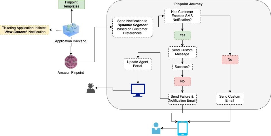
Let’s dive a bit deeper into each of these pieces and how to deploy the solution.

Walkthrough

The following are the high-level steps we will be walking through in the rest of this post.

  • Deploy SAM template that will provision all pieces of the solution. Checkout the Using container image support for AWS Lambda with AWS SAM blog post for more details.
  • Invoke the AMI version monitoring AWS Lambda function. The EventBridge rule is configured for a daily trigger and for the purposes of this blog post, we do not want to wait that long prior to seeing the pipeline in action.
  • View the details of the resultant image after the Image Builder Pipeline completes

Deploying the Solution

The first step to deploying the solution is to create the Elastic Container Registry Repository that will be used to upload the image artifacts created. You can do so using the following AWS CLI or AWS Tools for PowerShell command:

aws ecr create-repository --repository-name elastic-beanstalk-image-pipeline-trigger --image-tag-mutability IMMUTABLE --image-scanning-configuration scanOnPush=true --region us-east-1
New-ECRRepository -RepositoryName elastic-beanstalk-image-pipeline-trigger -ImageTagMutability IMMUTABLE -ImageScanningConfiguration_ScanOnPush $True -Region us-east-1

This will return output similar to the following. Take note of the repositoryUri as you will be using that in an upcoming step.

ECR repository creation output

Figure 5 – ECR repository creation output

With the repository configured, you are ready to get the solution. Either download or clone the project’s aws-samples/elastic-beanstalk-image-pipeline-trigger GitHub repository to a local directory. Once you have the project downloaded, you can compile it using the following command from the project’s src/BeanstalkImageBuilderPipeline directory.

dotnet publish -c Release -o ./bin/Release/net5.0/linux-x64/publish

The output should look like:

NET project compilation output

Figure 6 – .NET project compilation output

Now that the project is compiled, you are ready to create the container image by executing the following SAM CLI command.

sam build --template-file ./serverless.template
SAM build command output

Figure 7 – SAM build command output

Next up deploy the SAM template with the following command, replacing REPOSITORY_URL with the URL of the ECR repository created earlier:

sam deploy --stack-name elastic-beanstalk-image-pipeline --image-repository <REPOSITORY_URL> --capabilities CAPABILITY_IAM --region us-east-1

The SAM CLI will both push the container image and create the CloudFormation Stack, deploying all resources needed for this solution. The deployment output will look similar to:

SAM deploy command output

Figure 8 – SAM deploy command output

With the CloudFormation Stack completed, you are ready to move onto starting the pipeline to create a custom Windows AMI with the medium DISA STIG applied.

Invoke AMI ID Monitoring Lambda

Let’s start by invoking the Lambda function, depicted in Figure 3, responsible for ensuring that the latest Elastic Beanstalk managed AMI ID is stored in Parameter Store.

aws lambda invoke --function-name BeanstalkManagedAmiMonitor response.json --region us-east-1
Invoke-LMFunction -FunctionName BeanstalkManagedAmiMonitor -Region us-east-1
Lambda invocation output

Figure 9 – Lambda invocation output

The Lambda’s CloudWatch log group contains the BeanstalkManagedAmiMonitor function’s output. For example, below you can see that the SSM parameter is being updated with the new AMI ID.

BeanstalkManagedAmiMonitor Lambda’s log

Figure 10 – BeanstalkManagedAmiMonitor Lambda’s log

After this Lambda function updates the Parameter Store parameter with the latest AMI ID, the EC2 Image Builder recipe will be updated to use this AMI ID as the parent image, and the Image Builder pipeline will be started. You can see evidence of this by going to the ImageBuilderTrigger Lambda function’s CloudWatch log group. Below you can see a log entry with the message “Starting image pipeline execution…”.

ImageBuilderTrigger Lambda’s log

Figure 11 – ImageBuilderTrigger Lambda’s log

To keep track of the status of the image creation, navigate to the EC2 Image Builder console, and select the 1.0.1 version of the demo-beanstalk-image.

EC2 Image Builder images list

Figure 12 – EC2 Image Builder images list

This will display the details for that build. Keep an eye on the status. While the image is being create, you will see the status as “Building”. Applying the latest Windows updates and DISA STIG can take about an hour.

EC2 Image Builder image build version details

Figure 13 – EC2 Image Builder image build version details

Once the AMI has been created, the status will change to “Available”. Click on the version column’s link to see the details of that version.

EC2 Image Builder image build version details

Figure 14 – EC2 Image Builder image build version details

You can use the AMI ID listed when creating an Elastic Beanstalk application. When using the create new environment wizard, you can modify the capacity settings to specify this custom AMI ID. The automation is configured to run on a daily basis. Only for the purposes of this post, did we have to invoke the Lambda function directly.

Cleaning up

To avoid incurring future charges, delete the resources using the following commands, replacing the AWS_ACCOUNT_NUMBER placeholder with appropriate value.

aws imagebuilder delete-image --image-build-version-arn arn:aws:imagebuilder:us-east-1:<AWS_ACCOUNT_NUMBER>:image/demo-beanstalk-image/1.0.1/1 --region us-east-1

aws imagebuilder delete-image-pipeline --image-pipeline-arn arn:aws:imagebuilder:us-east-1:<AWS_ACCOUNT_NUMBER>:image-pipeline/windowsbeanstalkimagepipeline --region us-east-1

aws imagebuilder delete-image-recipe --image-recipe-arn arn:aws:imagebuilder:us-east-1:<AWS_ACCOUNT_NUMBER>:image-recipe/demo-beanstalk-image/1.0.1 --region us-east-1

aws cloudformation delete-stack --stack-name elastic-beanstalk-image-pipeline --region us-east-1

aws cloudformation wait stack-delete-complete --stack-name elastic-beanstalk-image-pipeline --region us-east-1

aws ecr delete-repository --repository-name elastic-beanstalk-image-pipeline-trigger --force --region us-east-1
Remove-EC2IBImage -ImageBuildVersionArn arn:aws:imagebuilder:us-east-1:<AWS_ACCOUNT_NUMBER>:image/demo-beanstalk-image/1.0.1/1 -Region us-east-1

Remove-EC2IBImagePipeline -ImagePipelineArn arn:aws:imagebuilder:us-east-1:<AWS_ACCOUNT_NUMBER>:image-pipeline/windowsbeanstalkimagepipeline -Region us-east-1

Remove-EC2IBImageRecipe -ImageRecipeArn arn:aws:imagebuilder:us-east-1:<AWS_ACCOUNT_NUMBER>:image-recipe/demo-beanstalk-image/1.0.1 -Region us-east-1

Remove-CFNStack -StackName elastic-beanstalk-image-pipeline -Region us-east-1

Wait-CFNStack -StackName elastic-beanstalk-image-pipeline -Region us-east-1

Remove-ECRRepository -RepositoryName elastic-beanstalk-image-pipeline-trigger -IgnoreExistingImages $True -Region us-east-1

Conclusion

In this post, you learned how to leverage EC2 Image Builder, Lambda, and EventBridge to automate the creation of a Windows AMI with the medium DISA STIGs applied that can be used for Elastic Beanstalk environments. Don’t stop there though, you can apply these same techniques whenever you need to base recipes on AMIs that the image origin is not available in EC2 Image Builder.

Further Reading

EC2 Image Builder has a number of image origins supported out of the box, see the Automate OS Image Build Pipelines with EC2 Image Builder blog post for more details. EC2 Image Builder is also not limited to just creating AMIs. The Build and Deploy Docker Images to AWS using EC2 Image Builder blog post shows you how to build Docker images that can be utilized throughout your organization.

These resources can provide additional information on the topics touched on in this article:

Carlos Santos

Carlos Santos

Carlos Santos is a Microsoft Specialist Solutions Architect with Amazon Web Services (AWS). In his role, Carlos helps customers through their cloud journey, leveraging his experience with application architecture, and distributed system design.