Post Syndicated from The History Guy: History Deserves to Be Remembered original https://www.youtube.com/watch?v=cftiHJKQSP0
Native Rust support on Cloudflare Workers
Post Syndicated from Steve Manuel original https://blog.cloudflare.com/workers-rust-sdk/


You can now write Cloudflare Workers in 100% Rust, no JavaScript required. Try it out: https://github.com/cloudflare/workers-rs
Cloudflare Workers has long supported the building blocks to run many languages using WebAssembly. However, there has always been a challenging “trampoline” step required to allow languages like Rust to talk to JavaScript APIs such as fetch().
In addition to the sizable amount of boilerplate needed, lots of “off the shelf” bindings between languages don’t include support for Cloudflare APIs such as KV and Durable Objects. What we wanted was a way to write a Worker in idiomatic Rust, quickly, and without needing knowledge of the host JavaScript environment. While we had a nice “starter” template that made it easy enough to pull in some Rust libraries and use them from JavaScript, the barrier was still too high if your goal was to write a full program in Rust and ship it to our edge.
Not anymore!
Introducing the worker crate, available on GitHub and crates.io, which makes Rust developers feel right at home on the Workers platform by running code inside the V8 WebAssembly engine. In the snippet below, you can see how the worker crate does all the heavy lifting by providing Rustacean-friendly Workers APIs.
use worker::*;

#[event(fetch)]
pub async fn main(req: Request, env: Env) -> Result<Response> {
    console_log!(
        "{} {}, located at: {:?}, within: {}",
        req.method().to_string(),
        req.path(),
        req.cf().coordinates().unwrap_or_default(),
        req.cf().region().unwrap_or("unknown region".into())
    );

    if !matches!(req.method(), Method::Post) {
        return Response::error("Method Not Allowed", 405);
    }

    if let Some(file) = req.form_data().await?.get("file") {
        return match file {
            FormEntry::File(buf) => {
                Response::ok(&format!("size = {}", buf.bytes().await?.len()))
            }
            _ => Response::error("`file` part of POST form must be a file", 400),
        };
    }

    Response::error("Bad Request", 400)
}
Get your own Worker in Rust started with a single command:
# see installation instructions for our `wrangler` CLI at https://github.com/cloudflare/wrangler
# (requires v1.19.2 or higher)
$ wrangler generate --type=rust my-project
We’ve stripped away all the glue code, provided an ergonomic HTTP framework, and baked in what you need to build small scripts or full-fledged Workers apps in Rust. You’ll find fetch, a router, easy-to-use HTTP functionality, Workers KV stores and Durable Objects, secrets, and environment variables too. It’s all open source, and we’d love your feedback!
Why are we doing this?
Cloudflare Workers is on a mission to simplify the developer experience. When we took a hard look at the previous experience writing non-JavaScript Workers, we knew we could do better. Rust happens to be a great language for us to kick-start our mission: it has first-class support for WebAssembly, and a wonderful, growing ecosystem. Tools like wasm-bindgen, libraries like web-sys, and Rust’s powerful macro system gave us a significant starting-off point. Plus, Rust’s popularity is growing rapidly, and if our own use of Rust at Cloudflare is any indication, there is no question that Rust is staking its claim as a must-have in the developer toolbox.
So give it a try, leave some feedback, even open a PR! By the way, we’re always on the lookout for great people to join us, and we are hiring for many open roles (including Rust engineers!) — take a look.
More Detail on the Juniper Hack and the NSA PRNG Backdoor
Post Syndicated from Bruce Schneier original https://www.schneier.com/blog/archives/2021/09/more-detail-on-the-juniper-hack-and-the-nsa-prng-backdoor.html
We knew the basics of this story, but it’s good to have more detail.
Here’s me in 2015 about this Juniper hack. Here’s me in 2007 on the NSA backdoor.
Какви са проблемите на системата за преброяването?
Post Syndicated from Bozho original https://blog.bozho.net/blog/3811
Проблемите на НСИ са сложни и многопластови и не могат да се обяснят просто с посочване на някого с пръст. Трябва, обаче, да търсят дългосрочни решения, а не оправдания.
Струва ми се, обаче, в ИТ общността си представя нещата малко по-просто, отколкото са. Това не е „един уебсайт“, на който просто трябва да сложиш достатъчно хардуер, за да работи. Ето няколко публично известни факта, които да помогнат интерпретацията:
- НСИ е направил поръчка за готова система за преброяване, а не за разработка на такава. Като цяло разумно решение. Местният партньор на шведската фирма „производител“ е СкейлФокус, които е трябвало да направят инсталация, конфигурация и поддръжка. Много често компании предпочитат да имат местни партньори, при които отива процент от продажбата, т.нар. two tier (или понякога three tier) distribution model. Цената е за лиценз, инсталация и конфигурация и като цяло изглежда разумна. Функционалностите са доста повече от
онлайн форми (на който му е интересно, техническото задание, предложението и договорът са на сайта на НСИ) - DDoS атаката е сериозна – ако наистина 250 гигабита в секунда са се „изсипали“ срещу системата, то на чисто софтуерно ниво няма какво да се направи – „тръбата“ се запушва, дори приложението да може да обработи данните. Засега няма причина да смятаме, че тази информация е грешна, най-много да е малко преувеличена, но дори да е наполовина, пак е значителна. Не съм съгласен, че „какво толкова сложно има да се защити една система“ – това не е софтуерен проблем, а мрежови. И няма прости и евтини решения.
- НСИ не са били подготвени за такава атака, а е трябвало. Ползването на CloudFlare е недостатъчна мярка за критичността и репутационните щети. Обикновено проблемът с CloudFlare е не самият CloudFlare, а това, че по други данни (исторически и настоящи DNS записи и просто логическо мислене) може да се прескочи CloudFlare.
- Тук обаче ще вдигна нещата едно ниво по-нагоре – това не е проект на НСИ, това е национален проект. НСИ просто е натоварен с неговото изпълнение. На ниво държава изгелжда липсва адекватна подготовка за защита от DDoS. Държавна агенция „Електронно управление“ и ресорните вицепремиери до момента е трябвало да осигурят такава не само на НСИ, но и за всички системи. Тя не е евтина, но работи (чрез т.нар. scrubbing центрове, които „почистват“ мръсния трафик преди да го изпратят към системите.) Кадровото осигуряване също е важна тема – колко ИТ експерти има НСИ и на какво заплащане и можем ли да очакваме да свършат всичко? Това също е системен проблем в държавата.
- DDoS атаките рядко водят до изтичане на данни (сами по себе си – никога, но понякога се ползват за димна завеса, прикрирваща други действия; засега не изглежда да е такъв случаят).
- съдейки по съобщенията за грешка, които излизаха в предните два дни, е имало и чисто интеграционни проблеми за проверката на въведените лични данни. За тези проблеми няма добро оправдание, а причината е липсата на координация между институциите и липсата на отговорен за процеса.
На следващото заседание на комисията по дигитализация в Народното събрание ще изясним всички тези въпроси. А следващото постоянно правителство трябва да ги реши системно.
Материалът Какви са проблемите на системата за преброяването? е публикуван за пръв път на БЛОГодаря.
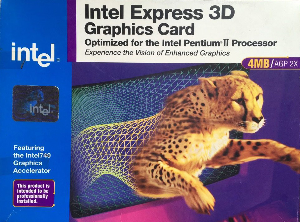
Remembering Intel 740 | Custom PC #218
Post Syndicated from Ben Hardwidge original https://www.raspberrypi.org/blog/remembering-intel-740-custom-pc-218/
With Intel attempting to get into 3D gaming graphics again, Custom PC’s Ben Hardwidge looks at the time it failed to take on 3dfx in the late 1990s.
Back in the late 1990s, I worked at a computer shop in Derby, where we sold components over the counter, while pointing to a sign that said ‘components are sold on the basis that the customer is competent to fit it themselves’. There were often compatibility issues between components, but there were two cards I’d always try to steer customers away from, as they nearly always came back to the shop, accompanied by a tired, angry face and colourful vocabulary.

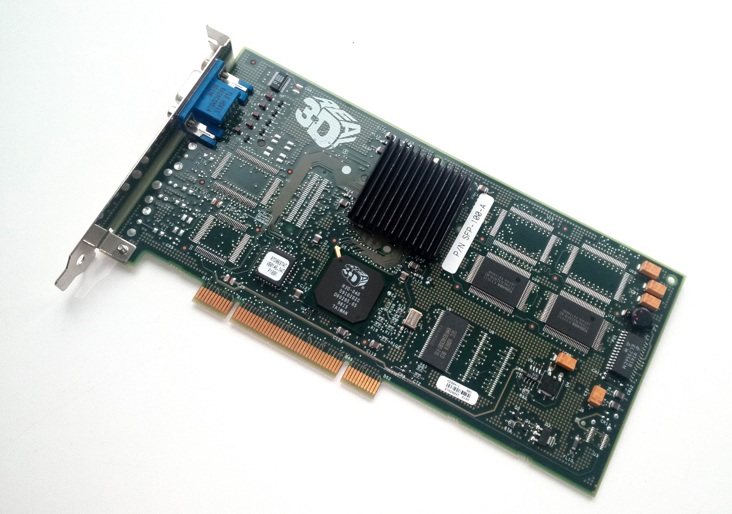
One was a PCI soft modem that required an MMX CPU and refused to cooperate with Freeserve, Dixons’ free ISP that was taking the UK by storm. The other was Express 3D graphics card, based on Intel’s 740 gaming chip.
This was before Nvidia had coined the term ‘GPU’ for its first GeForce cards, which could take the burden of transform and lighting calculations away from the CPU. The CPU was still expected to do a fair bit of work in the 3D pipeline, but you bought a 3D card to speed up the process and make games look much smoother than software rendering.
However, unlike the 3dfx Voodoo and VideoLogic PowerVR cards at the time, which required a 2D card to output to a monitor, the i740 wasn’t a sole 3D card – it could function as a 2D and a 3D card in one unit, and at £30 it was also cheap. You can see why people were drawn to it.
Another factor in its popularity was being made by Intel; thanks to the company’s relentless marketing campaigns, this meant people assumed it would just work without problems. It also used the brand-new Accelerated Graphics Port (AGP) interface, which people often assumed meant it would be faster than the PCI-based 3D accelerator cards.
The problem for us was that people who wanted cheap graphics cards usually also wanted cheap CPUs and motherboards, which meant going for an AMD K6 or Cyrix 6×86 CPU and a non-Intel motherboard chipset. The i740 didn’t like the AGP implementation on non-Intel chipsets very much, and it particularly didn’t like the ALi Aladdin chipset on which our most popular Super Socket 7 motherboards were based.
If you wanted the i740 to run properly, you really needed a Pentium II CPU and Intel 440LX or 440BX motherboard, and they were expensive. Then, once you’d paired your cheap graphics card with your expensive foundation gear, the i740 wasn’t actually that great, with comparably poor performance and still a load of compatibility issues. However, it had some interesting tech and history behind it that’s worth revisiting.
Aerospace beginnings
Intel didn’t have much in the way of graphics tech in the 1990s, but it had spotted a big market for 3D acceleration. The ATX motherboards for its latest Pentium II CPUs also came with an AGP slot, and a 3D AGP graphics card could potentially encourage people to upgrade (more on this later).
With little 3D accelerator expertise in house, Intel teamed up with US aerospace company Lockheed Martin to develop a consumer graphics card. That might seem a bit left field, but Lockheed Martin had acquired a variety of assets through various mergers and takeovers. In 1993, GE Aerospace was sold to Martin Marietta, and in 1995, Martin Marietta merged with Lockheed to form Lockheed Martin.
GE Aerospace was a division of General Electric, and its main business was providing systems and electronic gear to the aerospace and military industries, including simulators. In 1994, it started to branch out, working with Sega to produce the hardware for its Model 2 arcade machines, including 3D graphics tech for texture-mapped polygons and texture filtering. It was used for titles such as Daytona USA and Virtua Fighter 2.
In 1995, Lockheed Martin created a spin-off dedicated to consumer 3D graphics tech called Real3D, mostly using employees from GE Aerospace. Real3D worked with Sega on the 3D graphics hardware in its Model 3 cabinet, which was released in 1996, and then later began working with Intel to produce a consumer 3D graphics card, codenamed ‘Auburn’, which would become the 740.
An AGP showcase?
Intel had clear aims for the i740 when it was released in 1998 – it needed to be cheap and it needed to showcase the new AGP interface featured on the latest Pentium II motherboards. AGP had huge potential.
Although AGP was mainly based on the existing PCI interface, it had a direct connection to the CPU, as opposed to sharing the PCI bus with other cards. This not only freed up bandwidth, but also meant the AGP bus could run at a higher clock speed than the PCI bus.
Another one of its benefits was sideband addressing via a dedicated bus, meaning that all the usual address/data lines could be used solely for data throughput rather than both addressing and data functions, with the sideband bus handling address requests.
This massively increased the speed at which an AGP card could read from system memory compared with a PCI card, and meant an AGP card could practically use system memory as well as its on-board memory. You may remember the ‘AGP aperture’ setting in old motherboard BIOS screens – that was the amount of system memory you could allocate to your graphics card.
Most 3D cards didn’t rely on this feature, instead being piled with fast on-board memory to maximise performance, but Intel decided to go all out on it with the i740. The result was a card that only used its on-board memory as a frame buffer, with textures being stored in system memory.
This meant Intel could save money on memory (the cheapest i740 cards only came with 2MB compared to 8MB on the cheapest Voodoo2 cards), while also ensuring the cards required the new AGP interface.
The first problem, of course, was that using system memory and its interface wasn’t anywhere near as fast as using on-board graphics memory. The other problem was that the need for the graphics card to constantly access system memory ended up starving the CPU of memory bandwidth.
That was a big problem at a time when the CPU was still doing a fair bit of the work in the 3D pipeline. The growing use of larger textures in 3D games to improve detail made the situation even worse. What’s more, as I mentioned earlier, the AGP implementations on most Super Socket 7 motherboards just weren’t designed with a card such as the i740 in mind.
It also didn’t help that some board makers (including Real3D under the Starfighter brand) started making PCI versions of the i740 with a bridge chip and more on-board memory, and these cards were usually faster than the AGP equivalents, as they didn’t rely on system memory for texture storage.
Curtains for the i740
What seems bizarre now is that, at the time, I remember a lot of discussion before the launch about how Intel’s work with Real3D was going to result in Intel having a monopoly on 3D graphics, and putting the likes of ATi, 3dfx and VideoLogic out of business.
Intel had access to huge silicon manufacturing facilities, it had a massive research and development budget, and it had the proven expertise of Real3D at its disposal. In reality, the i740 was soon cancelled and almost completely forgotten by the end of 1999.
Custom PC #218 out NOW!
Get your hands on the latest issue of Custom PC at your usual outlet, or online from the Raspberry Pi Press store.

You can also download a PDF of Custom PC #218 for the bargain price of £0.00.
The post Remembering Intel 740 | Custom PC #218 appeared first on Raspberry Pi.
[$] LWN.net Weekly Edition for September 9, 2021
Post Syndicated from original https://lwn.net/Articles/868156/rss
The LWN.net Weekly Edition for September 9, 2021 is available.
17 additional AWS services authorized for DoD workloads in the AWS GovCloud Regions
Post Syndicated from Tyler Harding original https://aws.amazon.com/blogs/security/17-additional-aws-services-authorized-for-dod-workloads-in-the-aws-govcloud-regions/
I’m pleased to announce that the Defense Information Systems Agency (DISA) has authorized 17 additional Amazon Web Services (AWS) services and features in the AWS GovCloud (US) Regions, bringing the total to 105 services and major features that are authorized for use by the U.S. Department of Defense (DoD). AWS now offers additional services to DoD mission owners in these categories: business applications; computing; containers; cost management; developer tools; management and governance; media services; security, identity, and compliance; and storage.
Why does authorization matter?
DISA authorization of 17 new cloud services enables mission owners to build secure innovative solutions to include systems that process unclassified national security data (for example, Impact Level 5). DISA’s authorization demonstrates that AWS effectively implemented more than 421 security controls by using applicable criteria from NIST SP 800-53 Revision 4, the US General Services Administration’s FedRAMP High baseline, and the DoD Cloud Computing Security Requirements Guide.
Recently authorized AWS services at DoD Impact Levels (IL) 4 and 5 include the following:
Business Applications
- Amazon Simple Email Service (Amazon SES) – Inbound and outbound cloud email
- Amazon Pinpoint – Multichannel marketing communication
- AWS Marketplace – A digital catalog with thousands of software listings from independent software vendors that you can use to find, test, buy, and deploy software that runs on AWS
Compute
- AWS Fargate (a feature of Amazon Elastic Container Service (Amazon ECS) and Amazon Elastic Kubernetes Service (Amazon EKS)) – A serverless compute engine for containers
Containers
- Amazon Elastic Kubernetes Service (Amazon EKS) – A trusted way to run Kubernetes
Cost Management
- AWS Budgets – Set custom budgets to track your cost and usage, from the simplest to the most complex use cases
- AWS Cost Explorer – An interface that lets you visualize, understand, and manage your AWS costs and usage over time
- AWS Cost & Usage Report – Itemize usage at the account or organization level by product code, usage type, and operation
Developer Tools
- AWS CodePipeline – Automate continuous delivery pipelines for fast and reliable updates
- AWS X-Ray – Analyze and debug production and distributed applications, such as those built using a microservices architecture
Management & Governance
- AWS License Manager – Manage your software licenses from vendors
- AWS Personal Health Dashboard – Provide alerts and guidance for AWS events that might affect your environment
- AWS Systems Manager – An operations hub for AWS
Media Services
- Amazon Textract – Extract printed text, handwriting, and data from virtually any document
Security, Identity & Compliance
- Amazon Cognito – Secure user sign-up, sign-in, and access control
- AWS Security Hub – Centrally view and manage security alerts and automate security checks
Storage
- AWS Backup – Centrally manage and automate backups across AWS services
Figure 1 shows the IL 4 and IL 5 AWS services that are now authorized for DoD workloads, broken out into functional categories.

Figure 1: The AWS services newly authorized by DISA
To learn more about AWS solutions for the DoD, see our AWS solution offerings. Follow the AWS Security Blog for updates on our Services in Scope by Compliance Program. If you have feedback about this blog post, let us know in the Comments section below.
Want more AWS Security how-to content, news, and feature announcements? Follow us on Twitter.
Amazon Elasticsearch Service Is Now Amazon OpenSearch Service and Supports OpenSearch 1.0
Post Syndicated from Channy Yun original https://aws.amazon.com/blogs/aws/amazon-elasticsearch-service-is-now-amazon-opensearch-service-and-supports-opensearch-10/
In 2015, we launched Amazon Elasticsearch Service (Amazon ES), a fully managed service that makes it easy for you to perform interactive log analytics, real-time application monitoring, website search, and more.
Amazon ES has been a popular service for log analytics because of its ability to ingest high volumes of log data. Additionally, with UltraWarm and cold storage tiers, you can lower costs to one-tenth of traditional hot storage on Amazon ES. Because Amazon ES integrates with Logstash, Amazon Kinesis Data Firehose, Amazon CloudWatch Logs, and AWS IoT, you can select the secure data ingestion tool that meets your use case requirements.
Developers embrace open-source software for many reasons. One of the most important reasons is the freedom to use that software where and how they want. On January 21, 2021, Elastic NV announced that they would change their software licensing strategy. After Elasticsearch version 7.10.2 and Kibana 7.10.2, they will not release new versions of Elasticsearch and Kibana under the permissive 2.0 version of the Apache License (ALv2). Instead, Elastic NV is releasing Elasticsearch and Kibana under the Elastic license, with source code available under the Elastic License or Server Side Public License (SSPL). These licenses are not open source and do not offer users the same freedom.
For this reason, we decided to create and maintain OpenSearch, a community-driven, open-source fork from the last ALv2 version of Elasticsearch and Kibana. We are making a long-term investment in the OpenSearch project and recently released version 1.0.
OpenSearch provides a highly scalable system for providing fast access and response to large volumes of data with an integrated visualization tool, OpenSearch Dashboards, that makes it easy for users to explore their data. OpenSearch and OpenSearch Dashboards were originally derived from Elasticsearch 7.10.2 and Kibana 7.10.2. Like Elasticsearch and Apache Solr, OpenSearch is powered by the Apache Lucene search library.
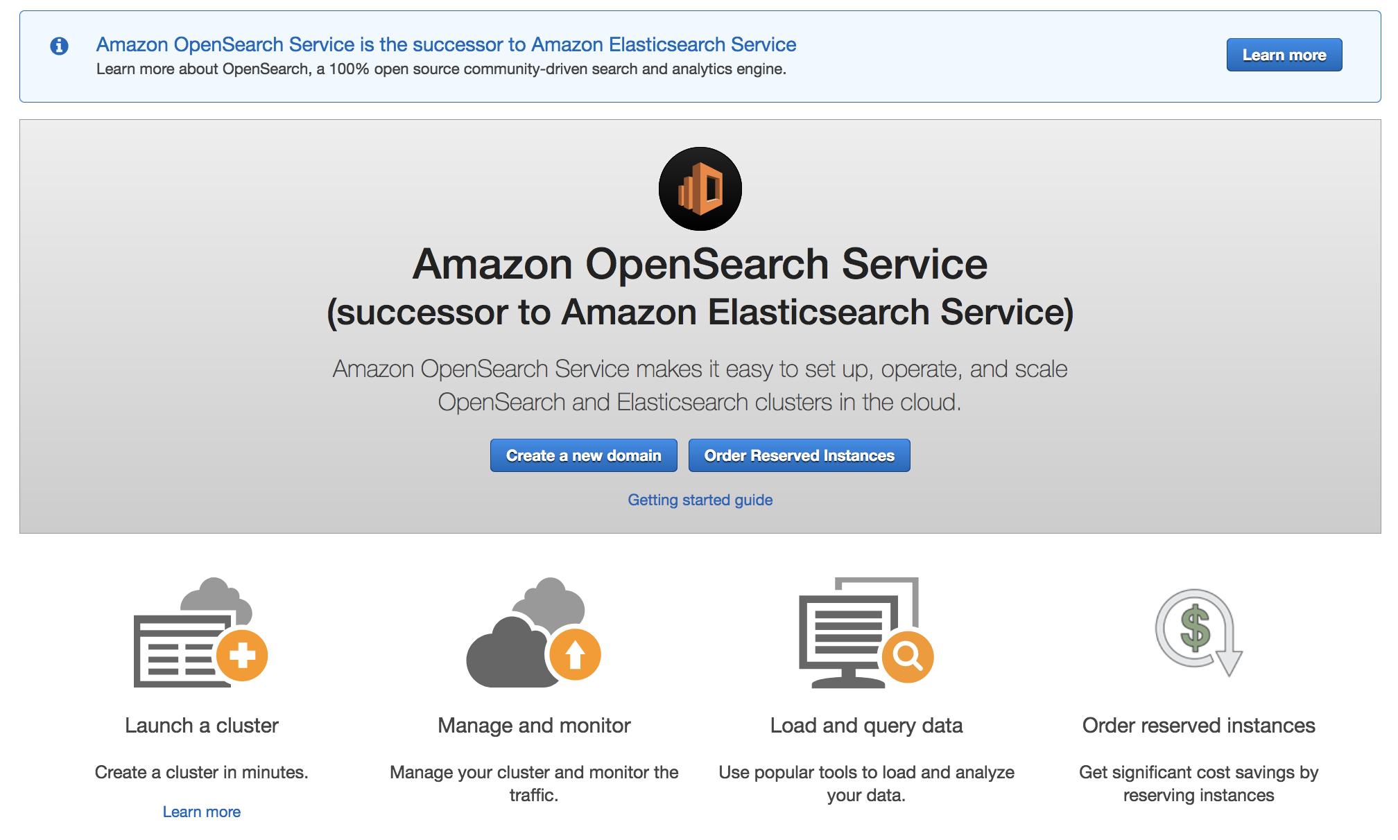
Announcing Amazon OpenSearch Service
Today, we rename Amazon Elasticsearch Service to Amazon OpenSearch Service because the service now supports OpenSearch 1.0. Although the name has changed, we will continue to deliver the same experiences without any negative impact to ongoing operations, development methodology, or business use.
Amazon OpenSearch Service offers a choice of open-source engines to deploy and run, including the currently available 19 versions of ALv2 Elasticsearch 7.10 and earlier and OpenSearch 1.0. We will continue to support and maintain the ALv2 Elasticsearch versions with security and bug fixes. We will deliver all-new features and functionality through OpenSearch and OpenSearch Dashboards. Amazon OpenSearch Service APIs will be backward-compatible with the existing service APIs, so there is no need for you to update your current client code or applications. We will keep clients of OpenSearch compatible with open source.
To get started, in the AWS Management Console, choose Create a domain. In Step 1: Choose deployment type, select OpenSearch 1.0 (latest).
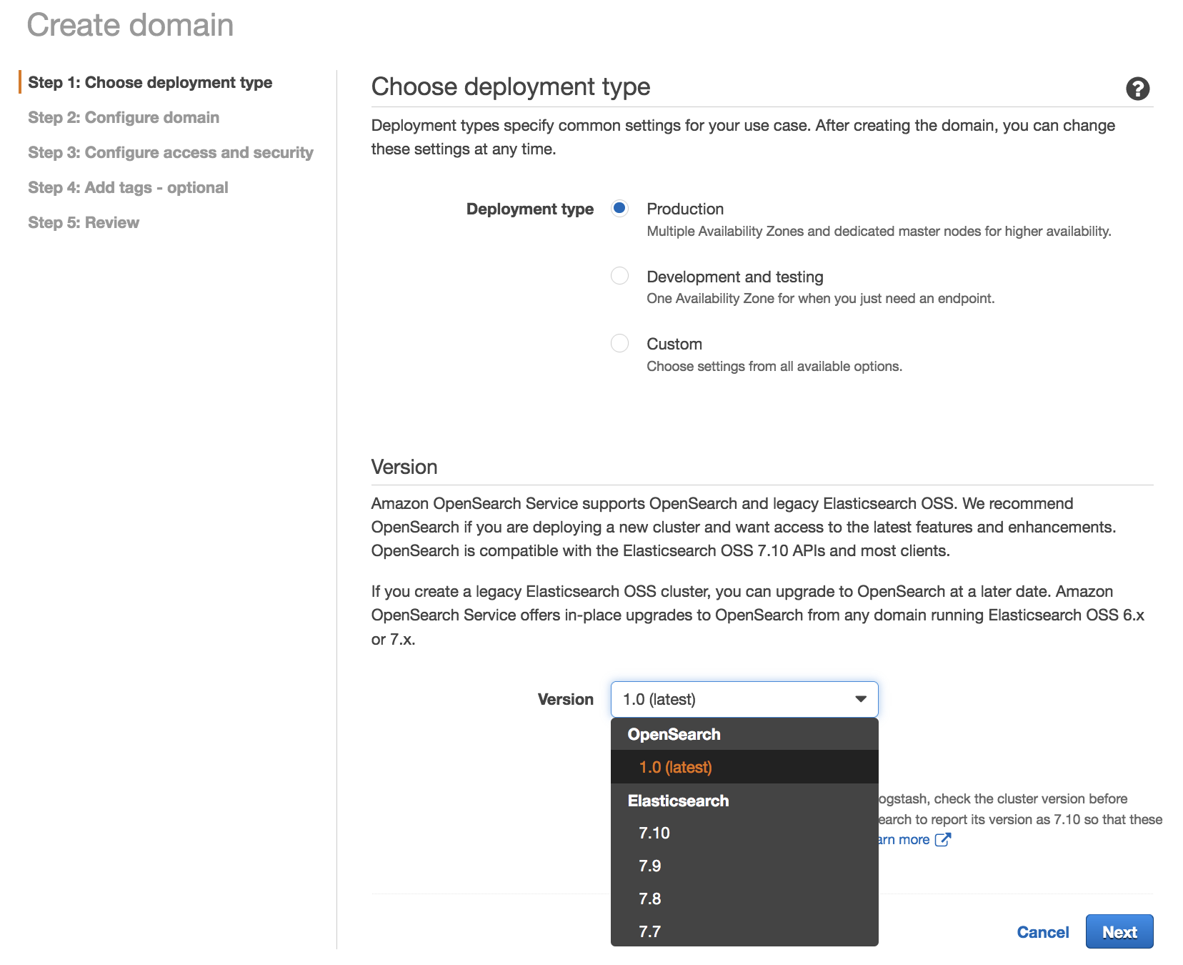
We recommend OpenSearch 1.0 if you are deploying a new cluster and want access to the latest features and enhancements. OpenSearch 1.0 is compatible with the open-source Elasticsearch 7.10 APIs and most clients.
Upgrading to OpenSearch 1.0
Amazon OpenSearch Service offers a seamless in-place upgrade path from existing Elasticsearch 6.x and 7.x managed clusters to OpenSearch. To upgrade a domain to OpenSearch 1.0 in the AWS Management Console, choose the domain that you want to upgrade, choose Actions, and then select Upgrade domain.
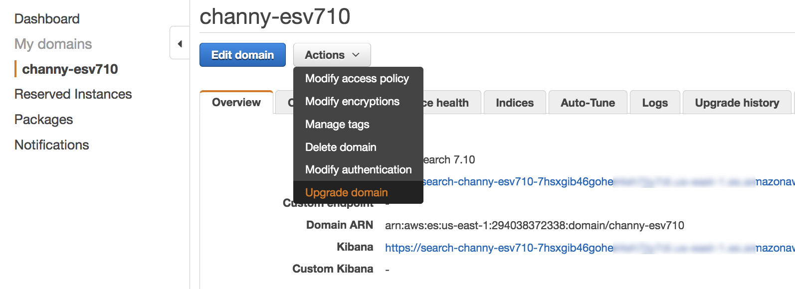
Next, you can select a version to upgrade to OpenSearch 1.0 for your existing domain without creating a separate domain and migrating your data.
The upgrade process is irreversible. It can’t be paused or canceled. During an upgrade, you can’t make configuration changes to the domain. Before you start an upgrade, you can perform the pre-upgrade checks for issues that can block an upgrade and take a snapshot of the cluster by selecting Check upgrade eligibility.
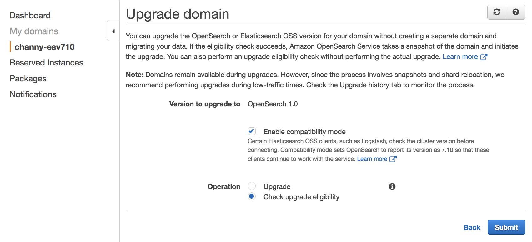
Amazon OpenSearch Services starts the upgrade, which can take from 15 minutes to several hours to complete. To learn more, see Upgrading Elasticsearch and Service Software Updates in Amazon OpenSearch Service Developer Guide.
OpenSearch Features
OpenSearch provides the following features that were not previously available in open-source Elasticsearch.
| Features | Description |
| Advanced Security | Offers encryption, authentication, authorization, and auditing features. They include integrations with Active Directory, LDAP, SAML, Kerberos, JSON web tokens, and more. OpenSearch also provides fine-grained, role-based access control to indices, documents, and fields. |
| SQL Query Syntax | Provides the familiar SQL query syntax. Use aggregations, group by, and where clauses to investigate your data. Read data as JSON documents or CSV tables so you have the flexibility to use the format that works best for you. |
| Reporting | Schedule, export, and share reports from dashboards, saved searches, alerts, and visualizations. |
| Anomaly Detection | Use machine learning anomaly detection based on the Random Cut Forest (RCF) algorithm to automatically detect anomalies as your data is ingested. Combine with alerting to monitor data in near real time and send alert notifications automatically. |
| Index Management | Define custom policies to automate routine index management tasks, such as rollover and delete, apply them to indices and index patterns, and transforms. |
| Performance Analyzer and RCA Framework | Query numerous cluster performance metrics and aggregations. Use PerfTop, the command line interface (CLI) to quickly display and analyze those metrics. Use the root cause analysis (RCA) framework to investigate performance and reliability issues in clusters. |
| Asynchronous Search | Run complex queries without worrying about the query timing out with Asynchronous Search queries running in the background. Track query progress and retrieve partial results as they become available. |
| Trace Analytics | Ingest and visualize OpenTelemetry data for distributed applications. Visualize the flow of events between these applications to identify performance problems. |
| Alerting | Automatically monitor data and send alert notifications to stakeholders. With an intuitive interface and a powerful API, easily set up, manage, and monitor alerts. Craft highly specific alert conditions using OpenSearch’s full query language and scripting capabilities. |
| k-NN search | Using machine learning, run the nearest neighbor search algorithm on billions of documents across thousands of dimensions with the same ease as running any regular OpenSearch query. Use aggregations and filter clauses to further refine similarity search operations. k-NN similarity search powers use cases such as product recommendations, fraud detection, image and video search, related document search, and more. |
| Piped Processing Language | Provides a familiar query syntax with a comprehensive set of commands delimited by pipes (|) to query data. |
| Dashboard Notebooks | Combine dashboards, visualizations, text, and more to provide context and detailed explanations when analyzing data. |
OpenSearch 1.0 supports three new features that are not available in the existing Elasticsearch versions supported on Amazon OpenSearch Service: Transforms, Data Streams, and Notebooks in OpenSearch Dashboards.
To engage with the OpenSearch community, we welcome pull requests through GitHub to fix bugs, improve performance and stability, or add new features. You can leave feedback in the OpenSearch community forum.
Now Available
Starting today, Amazon Elasticsearch Service has been renamed to Amazon OpenSearch Service in all AWS Regions. For more information, see the Amazon OpenSearch Service page.
You can send feedback to the AWS forum for Amazon OpenSearch Service or through your usual AWS Support contacts.
— Channy
[$] Applying PEP 8
Post Syndicated from original https://lwn.net/Articles/868490/rss
Two recent threads on the python-ideas mailing list have overlapped to a
certain extent; both referred to Python’s style guide, but the discussion
indicates that the advice in it may have been stretched further than intended. PEP 8
(“Style Guide for Python Code“) is the longstanding set of
guidelines and suggestions for code that is going into the standard
library, but the “rules” in the PEP have been applied in settings and tools well outside of that
realm. There may be reasons to update the PEP—some unrelated work of that nature is
ongoing, in fact—but Pythonistas need to remember that the suggestions in
it are not carved in stone.
EVERY home should have FLOOD sensors, here are the best ones.
Post Syndicated from The Hook Up original https://www.youtube.com/watch?v=-Lp_IrEqZ9M
Prevent THOUSANDS in damages with these smart water monitors.
Post Syndicated from The Hook Up original https://www.youtube.com/watch?v=5KPKhRwqoAA
Federated authentication to Amazon Redshift using AWS Single Sign-On
Post Syndicated from Manash Deb original https://aws.amazon.com/blogs/big-data/federated-authentication-to-amazon-redshift-using-aws-single-sign-on/
Managing database users through identity federation allows you to manage authentication and authorization procedures centrally. Amazon Redshift, a fast, fully managed cloud data warehouse, provides browser-based plugins for JDBC/ODBC drivers, which helps you easily implement identity federation capabilities added with multi-factor authentication (MFA) to secure your data warehouse, and also helps automation and enforcement of data access policies across the organization.
AWS Single Sign-On (AWS SSO) provides tools to federate access to users to the AWS environment. AWS SSO integrates with AWS Organizations to manage access to all the AWS accounts under the organization. In our previous post, we explained how you can integrate the Amazon Redshift browser-based Security Assertion Markup Language (SAML) plugin to add SSO and MFA capability with your federation identity provider (IdP). We expand on that in this post to show how you can set up this federated authentication to connect users to Amazon Redshift through AWS SSO integrated with a supported identity source directory of your choice, such as the native AWS SSO identity store, AWS managed or self-managed or on-premises Microsoft Active Directory (AD), or an external IdP such as Okta, Azure AD, or Ping.
Solution overview
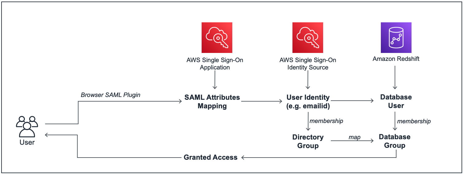
When you connect to Amazon Redshift using a JDBC/ODBC client, you can use the Amazon Redshift browser SAML plugin to launch a custom AWS SSO SAML application, which provides the SAML attributes required to connect to Amazon Redshift, after authenticating the user identity against the identity source directory that you have integrated with AWS SSO. The SAML application uses the user’s identity source credentials to get their user and group attributes, and grants the appropriate Amazon Redshift database access privileges to the user. The following diagram illustrates this workflow.
The following are the high-level steps for this setup:
- Enable AWS SSO (linked with your preferred identity source directory) and set up custom SAML applications in AWS SSO with the appropriate user or group association and attribute mappings.
- Set up a SAML IdP for AWS SSO and link it to an AWS Identity and Access Management (IAM) role with appropriate permissions to access Amazon Redshift.
- Set up the Amazon Redshift cluster and database groups that correspond to your AWS SSO directory groups.
- Configure the JDBC/ODBC client to authenticate with your AWS SSO SAML application and obtain federated IAM credentials to access the Amazon Redshift cluster.
Prerequisites
You need the following prerequisites to set up this solution:
- An AWS account with AWS SSO enabled, and linked to your identity source directory.
- An Amazon Redshift cluster.
- The Amazon Redshift JDBC driver (version 2.0+) downloaded and installed on your workstation.
- A SQL client of your preference. We use the SQL Workbench/J client in this post.
Use case
In this example use case, we use AWS SSO integrated with AWS Managed Microsoft AD as the identity source to connect to an Amazon Redshift cluster as users from two different AD groups: BI users and analysts. We create two SAML applications in AWS SSO to map these two groups with their respective users and then connect to Amazon Redshift using SQL Workbench/J client via AWS SSO using their Microsoft AD user credentials.
As a prerequisite step, we have already set up an AWS Managed Microsoft AD directory with sample directory groups and user mappings, and attached it to AWS SSO as the identity source.
The following screenshots show our AD groups and user mappings.
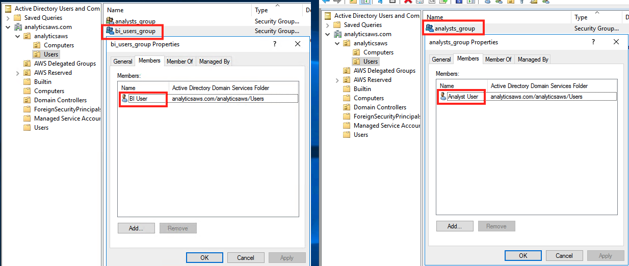
The following screenshot shows our AWS SSO identity source mapping.

Configure AWS SSO
As mentioned in the prerequisites section, you need to enable AWS SSO in your account, and map it with a supported identity source. If AWS SSO isn’t configured in your account, follow the steps in Getting Started.
In this step, you create two custom SAML applications in AWS SSO.
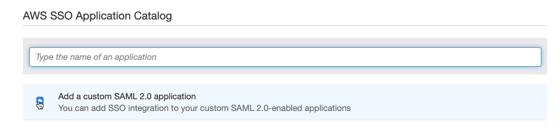
- On the AWS SSO console, choose Applications in the navigation pane.
- Choose Add a new application.

- Choose Add a custom SAML 2.0 application.

- For Display name, enter an appropriate name for the SAML application (for this post, because we create two applications, we first enter
Redshift-SAML-BI-User).

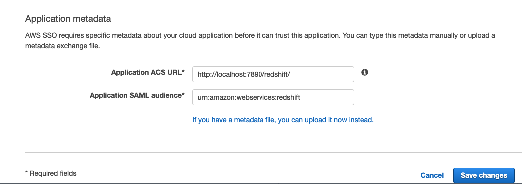
- In the Application metadata section, choose the option to manually enter the metadata values.

- For Application ACS URL, enter
http://localhost:7890/redshift/. - For Application SAML audience, enter
urn:amazon:webservices:redshift.

- On the Configuration tab, choose Download to download the AWS SSO SAML metadata file.


We use this file later to create the IdP.

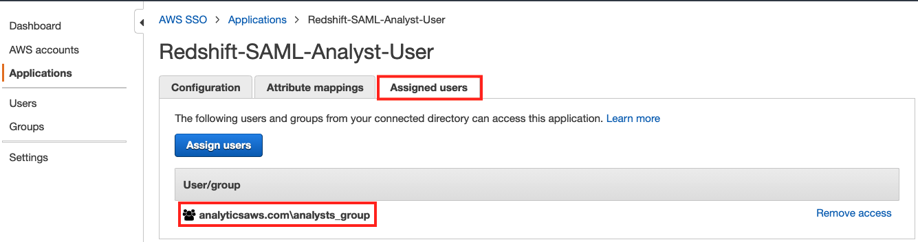
- On the Assigned users tab, choose Assign users to add
bi_users_groupto this application. - On the Attribute mappings tab, add the custom attribute mappings from the following table.
| User attribute in the application | Maps to this string value or user attribute in AWS SSO | Description |
Subject |
${user:email} |
User identity |
https://aws.amazon.com/SAML/Attributes/RoleSessionName |
${user:email} |
Identification for the user session, which in most cases is the email_id of the user |
https://redshift.amazon.com/SAML/Attributes/AutoCreate |
True |
If this parameter is set, new users authenticated by the IdP are automatically created in Amazon Redshift |
https://aws.amazon.com/SAML/Attributes/Role |
arn:aws:iam::<yourAWSAccountID>:role/redshift-federation-role,arn:aws:iam:: <yourAWSAccountID>:saml-provider/redshift-federation-saml-provider |
aws_idp_iam_role_arn, aws_identity_provider_arn |
https://redshift.amazon.com/SAML/Attributes/DbUser |
${user:email} |
Identification for the user session, which in most cases is the email_id of the user |
https://redshift.amazon.com/SAML/Attributes/DbGroups |
bi_users_group |
Amazon Redshift database group names for the user, which in most cases is the same as the directory groups the user belongs to |

The IAM role and IdP names and ARN strings entered for the https://aws.amazon.com/SAML/Attributes/Role attribute mapping must match the names given while creating those IAM resources for the BI user group during the IAM role setup in the next section.
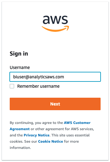
- Choose Dashboard in the navigation pane and choose the User portal URL link to launch the user portal’s login page in a new browser window.

- Log in to the AWS SSO user portal using your Microsoft AD user credentials for the BI user.


After logging in, you can see the new SAML application we created.
- Choose the application (right-click) and copy the link address.
We need this application login URL in a later step to connect to Amazon Redshift using AWS SSO federation.

- Similar to the preceding steps, create another SAML application called
Redshift-SAML-Analyst-Userand assign the analyst group to this application.

- On the application’s Attribute mappings tab, add all the attribute mappings similar to the previous application, but with different mapping values for the
RoleandDbGroupsattributes:- The
DbGroupsparameter should be mapped toanalysts_group. - The Role parameter value entered should match the names of IAM resources created for the analyst user group in the next section.

- The

- Log in to the AWS SSO user portal using your Microsoft AD user credentials for the analyst user.

- Copy the application link address, which you need in a later step to connect to Amazon Redshift using AWS SSO federation.


Set up IAM roles and SAML IdPs
In this step, you set up two SAML IdPs and two IAM roles with appropriate permissions for the two AD directory groups to access your Amazon Redshift cluster. You need the SAML Metadata XML files downloaded from your AWS SSO SAML applications from the previous section. As outlined in our earlier post, you may follow the step-by-step process to add the IdPs and IAM roles manually, or use the following AWS CloudFormation template.

Next, you need to confirm or replace the role ARN and the IdP ARN values in the two SAML applications’ attribute mappings. Refer to the following screenshot for the location of the two ARN values on the IAM console.

Set up an Amazon Redshift cluster
If you haven’t set up an Amazon Redshift cluster yet, see Getting started with Amazon Redshift for a step-by-step guide to create a new cluster in your AWS account.
If you already have an Amazon Redshift cluster, note the admin user credentials for that cluster and connect to that cluster using a SQL client like SQL Workbench/J and the latest Amazon Redshift JDBC driver.

After logging in to your Amazon Redshift cluster as an admin user, you can set up database objects and appropriate access permissions for them. In the following code, we set up two schemas for analysts and BI users, and then grant access on them to the relevant groups:
Connect to Amazon Redshift with AWS SSO federation
In this step, you connect to your Amazon Redshift cluster from your SQL Workbench/J client using AWS SSO federation.
- Create a new connection in SQL Workbench/J and choose Amazon Redshift as the driver.
- Enter the following code in the URL section of your connection properties (provide your Amazon Redshift cluster endpoint):
- Choose Extended Properties and add the following three properties:
- login_url – Enter the BI user group’s SAML application’s login URL you copied in an earlier step.
- plugin_name – Enter
com.amazon.redshift.plugin.BrowserSamlCredentialsProvider. - idp_response_timeout – Enter
60.

- Choose OK, and connect to your cluster.

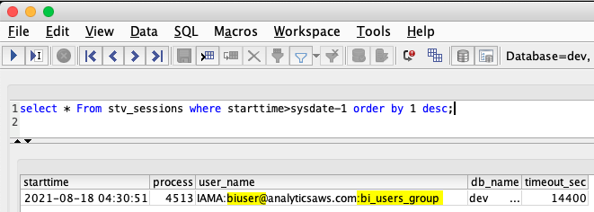
This launches your AWS SSO SAML application’s sign-in page in a browser window. After you successfully authenticate using the BI user’s AD user credentials in the browser, the SQL client connects you to Amazon Redshift as the BI user under the bi_users_group database group. You can verify the user’s database session and group association by running the following SQL:
- Similar to the BI user, you can create a new database connection to test an analyst user login. Instead of adding the extended properties in SQL Workbench, you can also use an initialization file to add the JDBC connection properties. For that, create a file
rsjdbc.inion your file system with the following contents (provide the analyst group’s SAML application’s login URL you copied earlier):
- Enter the following in the URL section of your connection properties (provide your cluster endpoint and file system path for the
rsjdbc.inifile you created in the previous step):
Your connection profile should look like the following screenshot.

- Choose OK to connect.
After you authenticate using the analyst user’s AD user credentials in the browser, you should be logged in to Amazon Redshift as the analyst user mapped to the analysts_group, as shown in the following screenshot.

Conclusion
In this post, we showed how you can use AWS SSO with AWS Managed Microsoft AD to federate access to Amazon Redshift using identity federation. The same setup instructions can also work with any other supported identity source directory of your choice, such as the native AWS SSO identity store, self-managed or on-premises Active Directory, or an external identity provider (IdP) such as Okta, Azure AD, and Ping.
About the Authors
 Manash Deb is a Software Development Engineer in AWS Redshift team. He has worked on building end-to-end data-driven solutions in different database and data warehousing technologies for over 15 years. He loves to learn new technologies and solving, automating, and simplifying customer problems with easy-to-use cloud data solutions on AWS.
 Manish Vazirani is an Analytics Specialist Solutions Architect at Amazon Web Services.
 Rajesh Mohan is an SDE-II at Amazon Studios where he engineers solutions to build a media supply chain to integrate content vendors with Prime Video. In his free time, he enjoys wandering the streets of New York City, trekking the mountains of California and binging on food videos while chomping away on delicious food from around the world.
Implement anti-money laundering solutions on AWS
Post Syndicated from Yomi Abatan original https://aws.amazon.com/blogs/big-data/implement-anti-money-laundering-solutions-on-aws/
The detection and prevention of financial crime continues to be an important priority for banks. Over the past 10 years, the level of activity in financial crimes compliance in financial services has expanded significantly, with regulators around the globe taking scores of enforcement actions and levying $36 billion in fines. Apart from the fines, the overall cost of compliance for global financial services companies is suspected to have reached $181 billion in 2020. For most banks, know your customer (KYC) and anti-money laundering (AML) constitute the largest area of concern within the broader financial crime compliance. In light of this, there is an urgent need to have effective AML systems that are scalable and fit for purpose in order to manage the risk of money laundering as well as the risk of non-compliance by the banks. Addressing money laundering at a high-level covers the following areas:
- Client screening and identity
- Transaction monitoring
- Extended customer risk profile
- Reporting of suspicious transactions
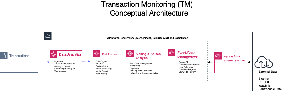
In this post we focus on transaction monitoring by looking at the general challenges with implementing transaction monitoring (TM) solutions and how AWS services can be leveraged to build a solution in the cloud from the perspectives of data analytics; risk management and ad hoc analysis. The following diagram is a conceptual architecture for a transaction monitoring solution on the AWS Cloud.
Current challenges
Due to growing digital channels for facilitating financial transactions, the increasing access to financial services for more people, and the growth in global payments; capturing and processing data related to TM is now considered a big data challenge. The big data challenges and observations include:
- The volume of data continues to prove to be too expansive for effective processing in a traditional on-premises data center solution.
- The velocity of banking transactions continues to rise despite the economic challenges of COVID-19.
- The variety of the data that needs to be processed for TM platforms continues to increase as more data sources with unstructured data become available. These data sources require techniques such as optical character recognition (OCR) and natural language processing (NLP) to automate the process of getting value out of such data without excessive manual effort.
- Finally, due to the layered nature of complex transactions involved in TM solutions, having data aggregated from multiple financial institutions provides a more comprehensive insight into the flow of financial transactions. Such an aggregation is usually less viable in a traditional on-premises solution.
Data Analytics
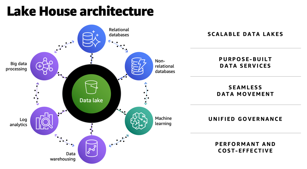
The first challenge with implementing TM solutions is having the tools and services to ingest data into a central store (often called a data lake) that is secure and scalable. Not only does this data lake need to capture terabytes or even petabytes of data, but it also needs to facilitate the process of moving data in and out of purpose-built data stores for time series, graph, data marts, and machine learning (ML) processing. In AWS, we refer to a data architecture which covers data lakes, purpose-built data stores and the data movement across data stores as a lake house architecture.
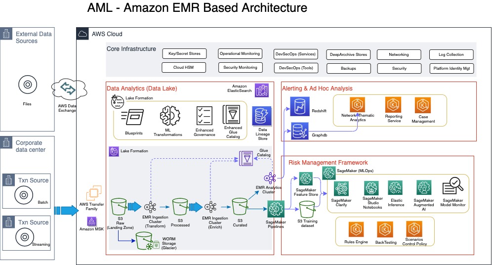
The following diagram illustrates a TM architecture on the AWS Cloud. This is a more detailed sample architecture of the lake house approach.
Ingestion of data into the lake house typically comes from a client’s data center (if the client is not already on the cloud), or from different client AWS accounts that host transaction systems or from external sources. For clients with transaction systems still on premises, we notice although several AWS services can be used to transfer data from on premises to the AWS Cloud, a number of our clients with a batch requirement utilize AWS Transfer Family, which provides fully managed support for secure file transfers directly into and out of Amazon Simple Storage Service (Amazon S3) or Amazon Elastic File System (Amazon EFS). With real-time requirements, we see the use of Amazon Managed Streaming for Apache Kafka (Amazon MSK), which is a fully managed service that makes it easy for you to build and run applications that use Apache Kafka to process streaming data. One other way to bring in reference data or external data like politically exposed persons (PEP) lists, watch lists, or stop lists for the AML process is via AWS Data Exchange, which makes it easy to find, subscribe to, and use third-party data in the cloud.
In this architecture, the ingestion process always stores the raw data in Amazon S3, which offers industry-leading scalability, data availability, security, and performance. For those clients already on the AWS Cloud, it’s very likely your data is already stored in Amazon S3.
For TM, the ingestion of the data comes from KYC systems, customer account stores, as well as transaction repositories. Data from KYC systems need to have the entity information, which can relate to a company or individual. For the corporate entities, information on the underlying beneficiary owners (UBOs)—the natural persons who directly or indirectly own or control a certain percentage of company—is also required. Before we discuss the data pipeline (the flow of data from the landing zone to the curated data layer) in detail, it’s important to address some of the security and audit requirements of the sensitive data classes typically used in AML processing.
According to Gartner, “Data governance is the specification of decision rights and an accountability framework to ensure the appropriate behavior in the valuation, creation, consumption, and control of data and analytics.” From an AML perspective, the specification and the accountable framework mentioned in this definition requires several enabling components.
The first is a data catalog, which is sometimes grouped into technical, process, and business catalogs. On the AWS platform, this catalog is provided either directly through AWS Glue or indirectly through AWS Lake Formation. Although the catalog implemented by AWS Glue is fundamentally a technical catalog, you can still extend it to add process and business relevant attributes.
The second enabling component is data lineage. This service should be flexible enough to support the different types of data lineage, namely vertical, horizontal, and physical. From an AML perspective, vertical lineage can provide a trace from AML regulation, which requires the collection of certain data classes, all the way to the data models captured in the technical catalog. Horizontal and physical lineage provide a trace of the data from source to eventual suspicious activity reporting for suspected transactions. Horizonal lineage provides lineage at the metadata level, whereas physical lineage captures trace at the physical level.
The third enabling component of data governance is data security. This covers several aspects of dealing with requirements of encryption of data at rest and in transit, but also de-identification of data during processing. This area requires a range of de-identification techniques depending on the context of use. Some of the techniques include tokenization, encryption, generalization, masking, perturbation, redaction, and even substitution of personally identifiable information (PII) or sensitive data usually at the attribute level. It’s important to use the right de-identification technique to enforce the right level of privacy while still ensuring the data still has sufficient inference signals for use in ML. You can use Amazon Macie, a fully managed data security and data privacy service that uses ML and pattern matching to discover and protect sensitive data, to automate PII discovery prior to applying the right de-identification technique.
Moving data from landing zone (raw data) all the way to curated data involves several steps of processing, including data quality validation, compression, transformation, enrichment, de-duplication, entity resolution, and entity aggregation. Such processing is usually referred to as extract, transform, and load (ETL). In this architecture, we have a choice of using a serverless architecture based on AWS Glue (using Scala or Python programming languages) or implementing Amazon EMR (a cloud big-data platform for processing large datasets using open-source tools such as Apache Spark and Hadoop). Amazon EMR provides the flexibility to run these ETL workloads on Amazon Elastic Compute Cloud (Amazon EC2) instances, Amazon Elastic Kubernetes Service (Amazon EKS) clusters and also on AWS Outposts.
Risk management framework
The risk management framework part of the architecture contains the rules, thresholds, algorithms, models, and control policies that govern the process of detecting and reporting suspicious transactions. Traditionally, most TM solutions have relied solely on rule-based controls to implement AML requirements. However, these rule-based implementations quickly become complex and difficult to maintain, as criminals find new and sophisticated ways to circumvent existing AML controls. Apart from the complexity and maintenance, rule-based approaches usually result in large number of false positives. False positives in this context are when transactions are flagged as suspicious but turn out not to be. Some of the numbers here are quite remarkable, with some studies revealing less than 2% of cases actually turning to be suspicious. The implication of this is the operational costs and the teams of operational resources required to investigate these false positives. Another implication that sometimes get overlooked is the customer experience, in which a customer service like payment or clearing of transactions is delayed or declined due to false positives. This usually leads to a less than satisfactory customer experience. Despite the number of false positives, AML failings and subsequent fines are hardly out of the news; in one case the Financial Conduct Authority (FCA) in the United Kingdom deciding to take the unprecedented step of bringing criminal proceedings against a bank over failed AML processes.
In light of some of the shortcomings of a rule-based AML approach, a lot of research and focus has been performed by financial services customers, including RegTechs, on applying ML to detect suspicious transactions. One comprehensive study on the use of ML techniques in suspicious transaction detection is a paper published by Z. Chen et al. This paper was published in 2018 (which in ML terms is a lifetime ago), but the concepts and findings are still relevant. The paper highlights some of the common algorithms and challenges with using ML for AML. AML data is a high-dimensional space that usually requires dimensionality reduction through the use of algorithms like Principal Component Analysis (PCA) or autoencoders (neural networks used to learn efficient data encodings in an unsupervised manner). As part of feature engineering, most algorithms require the value of transactions (debits and credits) aggregated by time intervals—daily, weekly, and monthly. Clustering algorithms like k-means or some variants of k-means are used to create clusters for customer or transaction profiles. There is also the need to deal with class imbalance usually found in AML datasets.
All of these algorithms referenced in the Z. Chen et al paper are supported by Amazon SageMaker. SageMaker is a fully managed ML service that allows data scientists and developers to easily build, train, and deploy ML models for AML. You can also implement some of the other categories of algorithms that support AML such as behavioral modelling, risk scoring, and anomaly detection with SageMaker. You can use a wide range of algorithms to address AML challenges, including supervised, semi-supervised, and unsupervised models. Some additional factors that determine the suitability of algorithms include high recall and precision rate of the models, and the ability to utilize approaches such as SHapley Additive exPlanation (SHAP) and Local Interpretable Model-Agnostic Explanations (LIME) values to explain the model output. Amazon SageMaker Clarify can detect bias and increases transparency of ML models.
Algorithms that focus on risk scoring enable a risk profile that can span across various data classes such as core customer attributes including industry, geography, bank product, business size, complex ownership structure for entities, as well as transactions (debits and credits) and frequency of such transactions. In addition, external data such as PEP lists, various stop lists and watch lists, and in some cases media coverage related to suspected fraud or corruption can also be weighted into a customer’s risk profile.
Rule-based and ML approaches aren’t mutually exclusive, but it’s likely that rules will continue to play a peripheral role as better algorithms are researched and implemented. One of the reasons why the development of algorithms for AML has been sluggish is the availability of reliable datasets, which include result data indicating when a correct suspicious activity report (SAR) was filed for a given scenario. Unlike other areas of ML in which findings have been openly shared for further research, with AML, a lot of the progress first appears in commercial products belonging to vendors who are protective of their intellectual property.
Ad hoc analysis and reporting
The final part of the architecture includes support for case or event management tooling and a reporting service for the eventual SAR. These services can be AWS Marketplace solutions or developed from scratch using AWS services such as Amazon EKS or Amazon ECS. This part of the architecture also provides support for a very important aspect of AML: network analytics. Network or link analysis has three main components:
- Clustering – The construction of graphs and representation of money flow. Amazon Neptune is a fast, reliable, fully managed graph database service that makes it easy to build and run applications that work with highly connected datasets.
- Statistical analysis – Used to assist with finding metrics around centrality, normality, clustering, and eigenvector centrality.
- Data visualization – An interactive and extensible data visualization platform to support exploratory data analysis. Findings from the network analytics can also feed into customer risk profiles and supervised ML algorithms.
Conclusion
None of the services or architecture layers described in this architecture are tightly coupled; different layers and services can be swapped with AWS Marketplace solutions or other FinTech or RegTech solutions that support cloud-based deployment. This means the AWS Cloud has a powerful ecosystem of native services and third-party solutions that can be deployed on the foundation of a Lake House Architecture on AWS to build a modern TM solution in the cloud. To find out more information about key of parts of the architecture described in this post, refer to the following resources:
For seeding data into a data lake (including taking advantage of ACID compliance):
- Simplify data integration pipeline development using AWS Glue custom blueprints
- Effective data lakes using AWS Lake Formation, Part 1: Getting started with governed tables
- Effective data lakes using AWS Lake Formation, Part 2: Creating a governed table for streaming data sources
For using Amazon EMR for data pipeline processing and some of recent updates to the Amazon EMR:
- Orchestrate an Amazon EMR on Amazon EKS Spark job with AWS Step Functions
- Amazon EMR 2020 year in review
For taking advantage of SageMaker to support financial crime use cases:
- Creating high-quality machine learning models for financial services using Amazon SageMaker Autopilot
- How Zopa enhanced their fraud detection application using Amazon SageMaker Clarify
- Detecting fraud in heterogeneous networks using Amazon SageMaker and Deep Graph Library
Please contact AWS if you need help developing a full-scale AML solution (covering client screening and identity, transaction monitoring, extended customer risk profile and reporting of suspicious transactions) on AWS.
About the Author
 Yomi Abatan is a Sr. Solution Architect based in London, United Kingdom. He works with financial services organisations, architecting, designing and implementing various large-scale IT solutions. He, currently helps established financial services AWS customers embark on Digital transformations using AWS cloud as an accelerator. Before joining AWS he worked in various architecture roles with several tier-one investment banks.
Orchestrate Jenkins Workloads using Dynamic Pod Autoscaling with Amazon EKS
Post Syndicated from Vladimir Toussaint original https://aws.amazon.com/blogs/devops/orchestrate-jenkins-workloads-using-dynamic-pod-autoscaling-with-amazon-eks/
This blog post will demonstrate how to leverage Jenkins with Amazon Elastic Kubernetes Service (EKS) by running a Jenkins Manager within an EKS pod. In doing so, we can run Jenkins workloads by allowing Amazon EKS to spawn dynamic Jenkins Agent(s) in order to perform application and infrastructure deployment. Traditionally, customers will setup a Jenkins Manager-Agent architecture that contains a set of manually added nodes with no autoscaling capabilities. Implementing this strategy will ensure that a robust approach optimizes the performance with the right-sized compute capacity and work needed to successfully perform the build tasks.
In setting up our Amazon EKS cluster with Jenkins, we’ll utilize the eksctl simple CLI tool for creating clusters on EKS. Then, we’ll build both the Jenkins Manager and Jenkins Agent image. Afterward, we’ll run a container deployment on our cluster to access the Jenkins application and utilize the dynamic Jenkins Agent pods to run pipelines and jobs.
Solution Overview
The architecture below illustrates the execution steps.

Figure 1. Solution overview diagram
Disclaimer(s): (Note: This Jenkins application is not configured with a persistent volume storage. Therefore, you must establish and configure this template to fit that requirement).
To accomplish this deployment workflow, we will do the following:
Centralized Shared Services account
- Deploy the Amazon EKS Cluster into a Centralized Shared Services Account.
- Create the Amazon ECR Repository for the Jenkins Manager and Jenkins Agent to store docker images.
- Deploy the kubernetes manifest file for the Jenkins Manager.
Target Account(s)
- Establish a set of AWS Identity and Access Management (IAM) roles with permissions for cross-across access from the Share Services account into the Target account(s).
Jenkins Application UI
- Jenkins Plugins – Install and configure the Kubernetes Plugin and CloudBees AWS Credentials Plugin from Manage Plugins (you will not have to manually install this since it will be packaged and installed as part of the Jenkins image build).
- Jenkins Pipeline Example—Fetch the Jenkinsfile to deploy an S3 Bucket with CloudFormation in the Target account using a Jenkins parameterized pipeline.
Prerequisites
The following is the minimum requirements for ensuring this solution will work.
Account Prerequisites
- Shared Services Account: The location of the Amazon EKS Cluster.
- Target Account: The destination of the CI/CD pipeline deployments.
Build Requirements
- AWS CLI
- Docker CLI — Note: The docker engine must be running in order to build images.
- aws-iam-authenticator
- kubectl
- eksctl
- Configure your AWS credentials with the associated region.
- Verify if the build requirements were correctly installed by checking the version.
- Create an EKS Cluster using eksctl.
- Verify that EKS nodes are running and available.
- Create an AWS ECR Repository for the Jenkins Manager and Jenkins Agent.
Clone the Git Repository
git clone https://github.com/aws-samples/jenkins-cloudformation-deployment-example.gitSecurity Considerations
This blog provides a high-level overview of the best practices for cross-account deployment and isolation maintenance between the applications. We evaluated the cross-account application deployment permissions and will describe the current state as well as what to avoid. As part of the security best practices, we will maintain isolation among multiple apps deployed in these environments, e.g., Pipeline 1 does not deploy to the Pipeline 2 infrastructure.
Requirement
A Jenkins manager is running as a container in an EC2 compute instance that resides within a Shared AWS account. This Jenkins application represents individual pipelines deploying unique microservices that build and deploy to multiple environments in separate AWS accounts. The cross-account deployment utilizes the target AWS account admin credentials in order to do the deployment.
This methodology means that it is not good practice to share the account credentials externally. Additionally, the deployment errors risk should be eliminated and application isolation should be maintained within the same account.
Note that the deployment steps are being run using AWS CLIs, thus our solution will be focused on AWS CLI usage.
The risk is much lower when utilizing CloudFormation / CDK to conduct deployments because the AWS CLIs executed from the build jobs will specify stack names as parametrized inputs and the very low probability of stack-name error. However, it remains inadvisable to utilize admin credentials of the target account.
Best Practice — Current Approach
We utilized cross-account roles that can restrict unauthorized access across build jobs. Behind this approach, we will utilize the assume-role concept that will enable the requesting role to obtain temporary credentials (from the STS service) of the target role and execute actions permitted by the target role. This is safer than utilizing hard-coded credentials. The requesting role could be either the inherited EC2 instance role OR specific user credentials. However, in our case, we are utilizing the inherited EC2 instance role.
For ease of understanding, we will refer the target-role as execution-role below.

Figure 2. Current approach
- As per the security best practice of assigning minimum privileges, we must first create execution role in IAM in the target account that has deployment permissions (either via CloudFormation OR via CLI’s), e.g., app-dev-role in Dev account and app-prod-role in Prod account.
- For each of those roles, we configure a trust relationship with the parent account ID (Shared Services account). This enables any roles in the Shared Services account (with assume-role permission) to assume the execution-role and deploy it on respective hosting infrastructure, e.g., the app-dev-role in Dev account will be a common execution role that will deploy various apps across infrastructure.
- Then, we create a local role in the Shared Services account and configure credentials within Jenkins to be utilized by the Build Jobs. Provide the job with the assume-role permissions and specify the list of ARNs across every account. Alternatively, the inherited EC2 instance role can also be utilized to assume the execution-role.
Create Cross-Account IAM Roles
Cross-account IAM roles allow users to securely access AWS resources in a target account while maintaining the observability of that AWS account. The cross-account IAM role includes a trust policy allowing AWS identities in another AWS account to assume the given role. This allows us to create a role in one AWS account that delegates specific permissions to another AWS account.
- Create an IAM role with a common name in each target account. The role name we’ve created is
AWSCloudFormationStackExecutionRole. The role must have permissions to perform CloudFormation actions and any actions regarding the resources that will be created. In our case, we will be creating an S3 Bucket utilizing CloudFormation. - This IAM role must also have an established trust relationship to the Shared Services account. In this case, the Jenkins Agent will be granted the ability to assume the role of the particular target account from the Shared Services account.
- In our case, the IAM entity that will assume the
AWSCloudFormationStackExecutionRoleis the EKS Node Instance Role that associated with the EKS Cluster Nodes.
{
    "Version": "2012-10-17",
    "Statement": [
        {
            "Effect": "Allow",
            "Action": [
                "cloudformation:CreateUploadBucket",
                "cloudformation:ListStacks",
                "cloudformation:CancelUpdateStack",
                "cloudformation:ExecuteChangeSet",
                "cloudformation:ListChangeSets",
                "cloudformation:ListStackResources",
                "cloudformation:DescribeStackResources",
                "cloudformation:DescribeStackResource",
                "cloudformation:CreateChangeSet",
                "cloudformation:DeleteChangeSet",
                "cloudformation:DescribeStacks",
                "cloudformation:ContinueUpdateRollback",
                "cloudformation:DescribeStackEvents",
                "cloudformation:CreateStack",
                "cloudformation:DeleteStack",
                "cloudformation:UpdateStack",
                "cloudformation:DescribeChangeSet",
                "s3:PutBucketPublicAccessBlock",
                "s3:CreateBucket",
                "s3:DeleteBucketPolicy",
                "s3:PutEncryptionConfiguration",
                "s3:PutBucketPolicy",
                "s3:DeleteBucket"
            ],
            "Resource": "*"
        }
    ]
}
Build Docker Images
Build the custom docker images for the Jenkins Manager and the Jenkins Agent, and then push the images to AWS ECR Repository. Navigate to the docker/ directory, then execute the command according to the required parameters with the AWS account ID, repository name, region, and the build folder name jenkins-manager/ or jenkins-agent/ that resides in the current docker directory. The custom docker images will contain a set of starter package installations.
Deploy Jenkins Application
After building both images, navigate to the k8s/ directory, modify the manifest file for the Jenkins image, and then execute the Jenkins manifest.yaml template to setup the Jenkins application. (Note: This Jenkins application is not configured with a persistent volume storage. Therefore, you will need to establish and configure this template to fit that requirement).
# Fetch the Application URL or navigate to the AWS Console for the Load Balancer
kubectl get svc -n jenkins

# Verify that jenkins deployment/pods are up running
kubectl get pods -n jenkins

# Replace with jenkins manager pod name and fetch Jenkins login password
kubectl exec -it pod/<JENKINS-MANAGER-POD-NAME> -n jenkins -- cat /var/jenkins_home/secrets/initialAdminPassword- The Kubernetes Plugin and CloudBees AWS Credentials Plugin should be installed as part of the Jenkins image build from the Managed Plugins.
- Navigate: Manage Jenkins → Configure Global Security
- Set the Crumb Issuer to remove the error pages in order to prevent Cross Site Request Forgery exploits.

Figure 3. Configure Global Security
Configure Jenkins Kubernetes Cloud
- Navigate: Manage Jenkins → Manage Nodes and Clouds → Configure Clouds
- Click: Add a new cloud → select Kubernetes from the drop menus

Figure 4a. Jenkins Configure Nodes and Clouds
Note: Before proceeding, please ensure that you can access your Amazon EKS cluster information, whether it is through Console or CLI.
- Enter a Name in the Kubernetes Cloud configuration field.
- Enter the Kubernetes URL which can be found via AWS Console by navigating to the Amazon EKS service and locating the API server endpoint of the cluster, or run the command
kubectl cluster-info. - Enter the namespace that will be utilized in the Kubernetes Namespace field. This will determine where the dynamic kubernetes pods will spawn. In our case, the name of the namespace is
jenkins. - During the initial setup of Jenkins Manager on kubernetes, there is an environment variable
JENKINS_URLthat automatically utilizes the Load Balancer URL to resolve requests. However, we will resolve our requests locally to the cluster IP address.- The format is as follows:
https://<service-name>.<namespace>.svc.cluster.local
- The format is as follows:

Figure 4b. Configure Kubernetes Cloud
Set AWS Credentials
Security concerns are a key reason why we’re utilizing an IAM role instead of access keys. For any given approach involving IAM, it is the best practice to utilize temporary credentials.
- You must have the AWS Credentials Binding Plugin installed before this step. Enter the unique ID name as shown in the example below.
- Enter the IAM Role ARN you created earlier for both the ID and IAM Role to use in the field as shown below.

Figure 5. AWS Credentials Binding

Figure 6. Managed Credentials
Create a pipeline
- Navigate to the Jenkins main menu and select new item
- Create a Pipeline

Figure 7. Create a pipeline
Configure Jenkins Agent
Setup a Kubernetes YAML template after you’ve built the agent image. In this example, we will be using the k8sPodTemplate.yaml file stored in the k8s/ folder.
CloudFormation Execution Scripts
This deploy-stack.sh file can accept four different parameters and conduct several types of CloudFormation stack executions such as deploy, create-changeset, and execute-changeset. This is also reflected in the stages of this Jenkinsfile pipeline. As for the delete-stack.sh file, two parameters are accepted, and, when executed, it will delete a CloudFormation stack based on the given stack name and region.
Jenkinsfile
In this Jenkinsfile, the individual pipeline build jobs will deploy individual microservices. The k8sPodTemplate.yaml is utilized to specify the kubernetes pod details and the inbound-agent that will be utilized to run the pipeline.
Jenkins Pipeline: Execute a pipeline
- Click Build with Parameters and then select a build action.

Figure 8a. Build with Parameters
- Examine the pipeline stages even further for the choice you selected. Also, view more details of the stages below and verify in your AWS account that the CloudFormation stack was executed.

Figure 8b. Pipeline Stage View
- The Final Step is to execute your pipeline and watch the pods spin up dynamically in your terminal. As is shown below, the Jenkins agent pod spawned and then terminated after the work completed. Watch this task on your own by executing the following command:
# Watch the pods spawn in the "jenkins" namespace
kubectl get pods -n jenkins -w

Figure 9. Watch Jenkins Agent Pods Spawn
Code Repository
References
Cleanup
In order to avoid incurring future charges, delete the resources utilized in the walkthrough.
- Delete the EKS cluster. You can utilize the
eksctlto delete the cluster. - Delete any remaining AWS resources created by EKS such as AWS LoadBalancer, Target Groups, etc.
- Delete any related IAM entities.
Conclusion
This post walked you through the process of building out Amazon EKS based infrastructure and integrating Jenkins to orchestrate workloads. We demonstrated how you can utilize this to deploy securely across multiple accounts with dynamic Jenkins agents and create alignment to your business with similar use cases. To learn more about Amazon EKS, see our documentation pages or explore our console.
About the Authors

Vladimir P. Toussaint
Vladimir is a DevOps Cloud Architect at Amazon Web Services. He works with GovCloud customers to build solutions and capabilities as they move to the cloud. Previous to Amazon Web Services, Vladimir has leveraged container orchestration tools such as Kubernetes to securely manage microservice applications for large enterprises.

Matt Noyce
Matt is a Sr. Cloud Application Architect at Amazon Web Services. He works primarily with health care and life sciences customers to help them architect and build applications, data lakes, and DevOps pipelines that solve their business needs. In his spare time Matt likes to run and hike along with enjoying time with friends and family.

Nikunj Vaidya
Nikunj is a DevOps Tech Leader at Amazon Web Services. He offers technical guidance to the customers on AWS DevOps solutions and services that would streamline the application development process, accelerate application delivery, and enable maintaining a high bar of software quality. Prior to AWS, Nikunj has worked in software engineering roles, leading transformation projects, driving releases and improvements in the software quality and customer experience.
Amazon EKS Anywhere – Now Generally Available to Create and Manage Kubernetes Clusters on Premises
Post Syndicated from Channy Yun original https://aws.amazon.com/blogs/aws/amazon-eks-anywhere-now-generally-available-to-create-and-manage-kubernetes-clusters-on-premises/
At AWS re:Invent 2020, we preannounced new deployment options of Amazon Elastic Container Service (Amazon ECS) Anywhere and Amazon Elastic Kubernetes Service (Amazon EKS) Anywhere in your own data center.
Today, I am happy to announce the general availability of Amazon EKS Anywhere, a deployment option for Amazon EKS that enables you to easily create and operate Kubernetes clusters on premises using VMware vSphere starting today. EKS Anywhere provides an installable software package for creating and operating Kubernetes clusters on premises and automation tooling for cluster lifecycle support.
EKS Anywhere brings a consistent AWS management experience to your data center, building on the strengths of Amazon EKS Distro, an open-source distribution for Kubernetes used by Amazon EKS.
EKS Anywhere is also Open Source. You can reduce the complexity of buying or building your own management tooling to create EKS Distro clusters, configure the operating environment, and update software. EKS Anywhere enables you to automate cluster management, reduce support costs, and eliminate the redundant effort of using multiple open-source or third-party tools for operating Kubernetes clusters. EKS Anywhere is fully supported by AWS. In addition, you can leverage the EKS console to view all your Kubernetes clusters, running anywhere.
We provide several deployment options for your Kubernetes cluster:
| Feature | Amazon EKS | EKS on Outposts | EKS Anywhere | EKS Distro |
| Hardware | Managed by AWS | Managed by customer | ||
| Deployment types | Amazon EC2, AWS Fargate (Serverless) | EC2 on Outposts | Customer Infrastructure | |
| Control plane management | Managed by AWS | Managed by customer | ||
| Control plane location | AWS cloud | Customer’s on-premises or data center | ||
| Cluster updates | Managed in-place update process for control plane and data plane | CLI (Flux supported rolling update for data plane, manual update for control plane) | ||
| Networking and Security | Amazon VPC Container Network Interface (CNI), Other compatible 3rd party CNI plugins | Cilium CNI | 3rd party CNI plugins | |
| Console support | Amazon EKS console | EKS console using EKS Connector | Self-service | |
| Support | AWS Support | EKS Anywhere support subscription | Self-service | |
EKS Anywhere integrates with a variety of products from our partners to help customers take advantage of EKS Anywhere and provide additional functionality. This includes Flux for cluster updates, Flux Controller for GitOps, eksctl – a simple CLI tool for creating and managing clusters on EKS, and Cilium for networking and security.
We also provide flexibility for you to integrate with your choice of tools in other areas. To add integrations to your EKS Anywhere cluster, see this list of suggested third-party tools for your consideration.
Get Started with Amazon EKS Anywhere
To get started with EKS Anywhere, you can create a bootstrap cluster in your machine for local development and test purposes. Currently, it allows you to create clusters in a VMWare vSphere environment for production workloads.
Let’s create a cluster on your desktop machine using eksctl! You can install eksctl and eksctl-anywhere with homebrew on Mac. Optionally, you can install some additional tools you may want for your EKS Anywhere clusters, such as kubectl. To learn more on Linux, see the installation guide in EKS Anywhere documentation.
$ brew install aws/tap/eks-anywhere
$ eksctl anywhere version
0.63.0
Generate a cluster config and create a cluster.
$ CLUSTER_NAME=dev-cluster
$ eksctl anywhere generate clusterconfig $CLUSTER_NAME \
    --provider docker > $CLUSTER_NAME.yaml
$ eksctl anywhere create cluster -f $CLUSTER_NAME.yaml
[i] Performing setup and validations
[v] validation succeeded {"validation": "docker Provider setup is valid"}
[i] Creating new bootstrap cluster
[i] Installing cluster-api providers on bootstrap cluster
[i] Provider specific setup
[i] Creating new workload cluster
[i] Installing networking on workload cluster
[i] Installing cluster-api providers on workload cluster
[i] Moving cluster management from bootstrap to workload cluster
[i] Installing EKS-A custom components (CRD and controller) on workload cluster
[i] Creating EKS-A CRDs instances on workload cluster
[i] Installing AddonManager and GitOps Toolkit on workload cluster
[i] GitOps field not specified, bootstrap flux skipped
[i] Deleting bootstrap cluster
[v] Cluster created!
Once your workload cluster is created, a KUBECONFIG file is stored on your admin machine with admin permissions for the workload cluster. You’ll be able to use that file with kubectl to set up and deploy workloads.
$ export KUBECONFIG=${PWD}/${CLUSTER_NAME}/${CLUSTER_NAME}-eks-a-cluster.kubeconfig
$ kubectl get ns
NAME                                STATUS   AGE
capd-system                         Active   21m
capi-kubeadm-bootstrap-system       Active   21m
capi-kubeadm-control-plane-system   Active   21m
capi-system                         Active   21m
capi-webhook-system                 Active   21m
cert-manager                        Active   22m
default                             Active   23m
eksa-system                         Active   20m
kube-node-lease                     Active   23m
kube-public                         Active   23m
kube-system                         Active   23m
You can create a simple test application for you to verify your cluster is working properly. Deploy and see a new pod running in your cluster, and forward the deployment port to your local machine with the following commands:
$ kubectl apply -f "https://anywhere.eks.amazonaws.com/manifests/hello-eks-a.yaml"
$ kubectl get pods -l app=hello-eks-a
NAME                                     READY   STATUS    RESTARTS   AGE
hello-eks-a-745bfcd586-6zx6b   1/1     Running   0          22m
$ kubectl port-forward deploy/hello-eks-a 8000:80
$ curl localhost:8000
⬡⬢⬡⬢⬡⬢⬡⬢⬡⬢⬡⬢⬡⬢⬡⬢⬡⬢⬡⬢⬡⬢⬡⬢⬡⬢⬡⬢⬡⬢⬡⬢⬡⬢⬡⬢⬡⬢⬡⬢⬡⬢⬡⬢⬡⬢⬡⬢⬡⬢⬡⬢⬡⬢⬡⬢⬡⬢

Thank you for using

███████╗██╗  ██╗███████╗
██╔════╝██║ ██╔╝██╔════╝
█████╗  █████╔╝ ███████╗
██╔══╝  ██╔═██╗ ╚════██║
███████╗██║  ██╗███████║
╚══════╝╚═╝  ╚═╝╚══════╝

 █████╗ ███╗   ██╗██╗   ██╗██╗    ██╗██╗  ██╗███████╗██████╗ ███████╗
██╔══██╗████╗  ██║╚██╗ ██╔╝██║    ██║██║  ██║██╔════╝██╔══██╗██╔════╝
███████║██╔██╗ ██║ ╚████╔╝ ██║ █╗ ██║███████║█████╗  ██████╔╝█████╗
██╔══██║██║╚██╗██║  ╚██╔╝  ██║███╗██║██╔══██║██╔══╝  ██╔══██╗██╔══╝
██║  ██║██║ ╚████║   ██║   ╚███╔███╔╝██║  ██║███████╗██║  ██║███████╗
╚═╝  ╚═╝╚═╝  ╚═══╝   ╚═╝    ╚══╝╚══╝ ╚═╝  ╚═╝╚══════╝╚═╝  ╚═╝╚══════╝

You have successfully deployed the hello-eks-a pod hello-eks-a-c5b9bc9d8-qp6bg

For more information check out
https://anywhere.eks.amazonaws.com

⬢⬡⬢⬡⬢⬡⬢⬡⬢⬡⬢⬡⬢⬡⬢⬡⬢⬡⬢⬡⬢⬡⬢⬡⬢⬡⬢⬡⬢⬡⬢⬡⬢⬡⬢⬡⬢⬡⬢⬡⬢⬡⬢⬡⬢⬡⬢⬡⬢⬡⬢⬡⬢⬡⬢⬡⬢⬡⬢
EKS Anywhere also supports a VMWare vSphere 7.0 version or higher for production clusters. To create a production cluster, see the requirements for VMware vSphere deployment and follow Create production cluster in EKS Anywhere documentation. It’s almost the same process as creating a test cluster on your machine.
A production-grade EKS Anywhere cluster should include at least three control plane nodes and three worker nodes on the vSphere for high availability and rolling upgrades. See the Cluster management in EKS Anywhere documentation for more information on common operational tasks like scaling, updating, and deleting the cluster.
EKS Connector – Public Preview
EKS Connector is a new capability that allows you to connect any Kubernetes clusters to the EKS console. You can connect any Kubernetes cluster, including self-managed clusters on EC2, EKS Anywhere clusters running on premises, and other Kubernetes clusters running outside of AWS to the EKS console. It makes it easy for you to view all connected clusters centrally.
To connect your EKS Anywhere cluster, visit the Clusters section in EKS console and select Register in the Add cluster drop-down menu.

Define a name for your cluster and select the Provider (if you don’t find an appropriate provider, select Other).

After registering the cluster, you will be redirected to the Cluster Overview page. Select Download YAML file to get the Kubernetes configuration file to deploy all the necessary infrastructure to connect your cluster to EKS.

Apply downloaded eks-connector.yaml and role binding eks-connector-binding.yaml file from the EKS Connector in our documentation. EKS Connector acts as a proxy and forwards the EKS console requests to the Kubernetes API server on your cluster, so you need to associate the connector’s service account with an EKS Connector Role, which gives permission to impersonate AWS IAM entities.
$ kubectl apply -f eks-connector.yaml
$ kubectl apply -f eks-connector-binding.yaml
After completing the registration, the cluster should be in the ACTIVE state.
$ eks describe-cluster --name "my-first-registered-cluster" --region ${AWS_REGION}Here is the expected output:
{
    "cluster": {
    "name": "my-first-registered-cluster",
    "arn": "arn:aws:eks:{EKS-REGION}:{ACCOUNT-ID}:cluster/my-first-registered-cluster",
    "createdAt": 1627672425.765,
    "connectorConfig": {
    "activationId": "xxxxxxxxACTIVATION_IDxxxxxxxx",
    "activationExpiry": 1627676019.0,
    "provider": "OTHER",
     "roleArn": "arn:aws:iam::{ACCOUNT-ID}:role/eks-connector-agent"
    },
  "status": "ACTIVE", "tags": {}
  }
}
EKS Connector is now in public preview in all AWS Regions where Amazon EKS is available. Please choose a region that’s closest to your cluster location to minimize latency. To learn more, visit EKS Connector in the Amazon EKS User Guide.
Things to Know
Here are a couple of things to keep in mind about EKS Anywhere:
Connectivity: There are three connectivity options: fully connected, partially disconnected, and fully disconnected. For fully connected and partially disconnected connectivity, you can connect your EKS Anywhere clusters to the EKS console via the EKS Connector and see the cluster configuration and workload status. You can leverage AWS services through AWS Controllers for Kubernetes (ACK). You can connect EKS Anywhere infrastructure resources using AWS System Manager Agents and view them using the SSM console.
Security Model: AWS follows the Shared Responsibility Model, where AWS is responsible for the security of the cloud, while the customer is responsible for security in the cloud. However, EKS Anywhere is an open-source tool, and the distribution of responsibility differs from that of a managed cloud service like Amazon EKS. AWS is responsible for building and delivering a secure tool. This tool will provision an initially secure Kubernetes cluster. To learn more, see Security Best Practices in EKS Anywhere documentation.
AWS Support: AWS Enterprise Support is a prerequisite for purchasing an Amazon EKS Anywhere Support subscription. If you would like business support for your EKS Anywhere clusters, please contact your Technical Account Manager (TAM) for details. Also, EKS Anywhere is supported by the open-source community. If you have a problem, open an issue and someone will get back to you as soon as possible.
Available Now
Amazon EKS Anywhere is now available to leverage EKS features with your on-premise infrastructure, accelerate adoption with partner integrations, managed add-ons, and curated open-source tools.
To learn more with a live demo and Q&A, join us for Containers from the Couch on September 13. You can see full demos to create a cluster and show admin workflows for scaling, upgrading the cluster version, and GitOps management.
Please send us feedback either through your usual AWS Support contacts, on the AWS Forum for Amazon EKS or on the container roadmap on Github.
– Channy
Данни за българите в Германия за 2020
Post Syndicated from original https://yurukov.net/blog/2021/bg-de-3/
Продължавам със серията от статии по темата. Може да видите предишните за 2016, 2017, 2018 и 2019. Освен поглед над размера на диаспората ни, в предишни години се фокусирах и върху други параметри като среден доход, образования, размер на домакинството и прочие. От DeStatis – германската статистическа служба – обещаха да обновят тези показатели по националност до края на септември, но предишни години имаха склонност да се забавят доста с този срок. Затова тук ще обърна внимание на нещо, за което писах вече миналата година – разминаването между различните оценки за българите в Германия.
Разбира се, има доста оценки правени на крак. Една от тях се намира в данните на МВнР, които показах, че са или отчасти стари, отчасти измислени. Друга беше на арестувания вече шеф на Агенцията за българите в чужбина, която също оборих. Темата е важна, защото не само може и следва да послужи за по-добро разпределение на консулствата ни в страната и планиране на изборни секции, но и да даде по-добра представа за настроенията и движението на българите из Европа. Това, впрочем, е и нещо, на което НСИ се опитва да получи отговор в рамките на течащото в момента преброяване.

Четирите важни числа за броя българи в Германия
Най-често цитираното число за българите в чужбина е 388700 към края на 2020 г. От тях 46.3% са жени. Него ще намерите както в българската страница на DW, така и по различни родни медии. Това е числото, което получаваме от таблица 12521-0002 на DeStatis и се отнася до „емигранти живеещи в Германия по националност“. С други думи данните идват от германската имиграционна служба и включва всички, които имат българско гражданство, но не и немско независимо къде са родени. Липсва информация по каква методология се следи, но от отговор на службата става дума, че не са правени ревизии и корекции от 2004-та насам. Това е първото число, което ще срещнете.
Второто число намираме в таблицата за населението – 12411-0009. Тя се води по подобние на следенето на населението в България – адресни регистрации, минаващи границата, социални и трудови регистри и прочие източници на информация. Методологията е доста точна предвид, че имаше под 1.5% корекция за 10 годишен период при предишното преброяване – както при НСИ, така и при DeStatis. Според тази таблица, в Германия има 368396 български граждани към края на 2020, 47.2% от тях са жени.
Третото число, което публикуваха миналата седмица включва хора живеещи в Германия „с български корени“. Те са около 270000, от които 49.3% са жени. Това число включва всички, които са родени в България или за чиито родители има данни, че са родени в България независимо дали живеят в същото домакинство или не. В това число не се влияе от гражданството – дали немско, българско, придобито при раждане или в последствие. В числото се включват всички деца родени в Германия, на които поне един родител е роден в България и емигрирал.
Докато последното число за хората с български произход включват тези получили германско гражданство, при първите две това липсва. По тази тема писах подробно миналата година, но накратко казано – имаме данните за последните 20 години и се вижда, че едва 2.7% от имащите право на гражданство се възползват и взимат такова. Все пак кумулативно за този период има малко над 25 хиляди българи са се възползвали. Преди 2007-ма, когато имаше изискване да се отказват от българския си паспорт, има значително по-малко на година, в голяма степен и защото е имало 10 пъти по-малко българи в страната. Все пак 3670 души са ни известни, които са се отказали от гражданство. Няма информация колко след 2007-ма са го възстановили. Има индикации обаче, че хора и след това са се отказвали по този начин без да са длъжни. Преди осем години направих допитване по въпроса.
Сериозна част от тези данни, която получава доста внимание, са децата родени в чужбина. Преброяването на последните е пословично трудно като имаме точни данни само за тези, а които родителите са си направили труда да изкарат български акт за раждане. Изкарах данните за тях и ги показаха в инфографика, за да разберем по-добре къде се намират. Те биват намесвани редовно в политически интриги и полемика. Наскоро тръгнаха слухове за „специални лични карти“ за тях. Преди това лидер на нео-наци партия настояваше, че се фалшифицирали данните за ражданията само защото не бил чул редовните апокалиптични новини в началото на годината.
Въпрос на дефиниция и методология
Събирайки данните така получаваме големи разминавания за Българите в Германия:
- 413 хил. без значение от гражданство според имиграционните
- 393 хил. без значение от гражданство според база данни население
- 388 хил. само с българско гражданство според имиграционните
- 368 хил. само с българско гражданство според база данни население
- 270 хил. с български произход без значение от гражданство
Ако взимаме тези числа буквално, излиза, че в Германия живеят между 100 и 140 хиляди души с български паспорт, но не родени в България. Според спорадичните изказвания на министри в медиите – какъвто е любимият контролиран метод за изкарване на данни със съмнително качество – около 153 хиляди души са получили българско гражданство между 1990 и 2018-та и броят им се увеличава с по няколко хиляди всяка година. Определено не са малко хората от Македония, Албания, Молдова и Русия, които са взели български паспорт и директно заминали за западна Европа и най-вече Германия. През консулството във Франкфурт редовно повечето на опашката са македонци. Добре документирани са и схемите са масова продажба на български паспорти на албански трафиканти и руски олигарси от страна на родните „патриотични“ партии, които от години контролират ДАБЧ с благословията на ГЕРБ. Така теоретично е възможно 60 до 90% от тях да са заминали директно към Германия.
Друг фактор са фиктивните регистрации по адрес с цел зачитане на престой заради социални или гражданство. DeStatis признаха, че е нещо, което въобще не е рядкост и че няма как да го контролират. Измеренията обаче и на този феномен са неизвестни. При липса на реално преброяване там с посещение по домовете, каквото имаме в България, не могат да получат точна картина. Все пак, тяхното ще е през май 2022 и през лятото ще получим по-добра картина за диаспортата ни, включително очакваната корекция с поне няколко процента надолу.
Попитах ги тези неща, но не очаквам конкретен отговор. Опитам се и да получа разбивка на български граждани живеещи в Германия по държава на раждане. Междувременно имаме разбивка по общини единствено от имиграционните. Тя показва само тези без немски паспорт. Числата тук са в известен смисъл надути, както описах по-горе, но са единствените позволяващи сравнение през годините по места. Затова макар да не може да разчитаме много на тях, подобно на тези на НЦОЗА ги публикувам отново като интерактивна карта:
The post Данни за българите в Германия за 2020 first appeared on Блогът на Юруков.
Jordan Shapiro | Father Figure: How to be a Feminist Dad | Talks at Google
Post Syndicated from Talks at Google original https://www.youtube.com/watch?v=w8Wz3HAm1kA
Securely Ingest Industrial Data to AWS via Machine to Cloud Solution
Post Syndicated from Ajay Swamy original https://aws.amazon.com/blogs/architecture/securely-ingest-industrial-data-to-aws-via-machine-to-cloud-solution/
As a manufacturing enterprise, maximizing your operational efficiency and optimizing output are critical factors in this competitive global market. However, many manufacturers are unable to frequently collect data, link data together, and generate insights to help them optimize performance. Furthermore, decades of competing standards for connectivity have resulted in the lack of universal protocols to connect underlying equipment and assets.
Machine to Cloud Connectivity Framework (M2C2) is an Amazon Web Services (AWS) Solution that provides the secure ingestion of equipment telemetry data to the AWS Cloud. This allows you to use AWS services to conduct analysis on your equipment data, instead of managing underlying infrastructure operations. The solution allows for robust data ingestion from industrial equipment that use OPC Data Access (OPC DA) and OPC Unified Access (OPC UA) protocols.
Secure, automated configuration and ingestion of industrial data
M2C2 allows manufacturers to ingest their shop floor data into various data destinations in AWS. These include AWS IoT SiteWise, AWS IoT Core, Amazon Kinesis Data Streams, and Amazon Simple Storage Service (S3). The solution is integrated with AWS IoT SiteWise so you can store, organize, and monitor data from your factory equipment at scale. Additionally, the solution provides customers an intuitive user interface to create, configure, monitor, and manage connections.
Automated setup and configuration

Figure 1. Automatically create and configure connections
With M2C2, you can connect to your operational technology assets (see Figure 1). The solution automatically creates AWS IoT certificates, keys, and configuration files for AWS IoT Greengrass. This allows you to set up Greengrass to run on your industrial gateway. It also automates the deployment of any Greengrass group configuration changes required by the solution. You can define a connection with the interface, and specify attributes about equipment, tags, protocols, and read frequency for equipment data.

Figure 2. Send data to different destinations in the AWS Cloud
Once the connection details have been specified, you can send data to different destinations in AWS Cloud (see Figure 2). M2C2 provides capability to ingest data from industrial equipment using OPC-DA and OPC-UA protocols. The solution collects the data, and then publishes the data to AWS IoT SiteWise, AWS IoT Core, or Kinesis Data Streams.
Publishing data to AWS IoT SiteWise allows for end-to-end modeling and monitoring of your factory floor assets. When using the default solution configuration, publishing data to Kinesis Data Streams allows for ingesting and storing data in an Amazon S3 bucket. This gives you the capability for custom advanced analytics use cases and reporting.
You can choose to create multiple connections, and specify sites, areas, processes, and machines, by using the setup UI.
Management of connections and messages

Figure 3. Manage your connections
M2C2 provides a straightforward connections screen (see Figure 3), where production managers can monitor and review the current state of connections. You can start and stop connections, view messages and errors, and gain connectivity across different areas of your factory floor. The Manage connections UI allows you to holistically manage data connectivity from a centralized place. You can then make changes and corrections as needed.
Architecture and workflow

Figure 4. Machine to Cloud Connectivity (M2C2) Framework architecture
The AWS CloudFormation template deploys the following infrastructure, shown in Figure 4:
- An Amazon CloudFront user interface that deploys into an Amazon S3 bucket configured for web hosting.
- An Amazon API Gateway API provides the user interface for client requests.
- An Amazon Cognito user pool authenticates the API requests.
- AWS Lambda functions power the user interface, in addition to the configuration and deployment mechanism for AWS IoT Greengrass and AWS IoT SiteWise gateway resources. Amazon DynamoDB tables store the connection metadata.
- An AWS IoT SiteWise gateway configuration can be used for any OPC UA data sources.
- An Amazon Kinesis Data Streams data stream, Amazon Kinesis Data Firehose, and Amazon S3 bucket to store telemetry data.
- AWS IoT Greengrass is installed and used on an on-premises industrial gateway to run protocol connector Lambda functions. These connect and read telemetry data from your OPC UA and OPC DA servers.
- Lambda functions are deployed onto AWS IoT Greengrass Core software on the industrial gateway. They connect to the servers and send the data to one or more configured destinations.
- Lambda functions that collect the telemetry data write to AWS IoT Greengrass stream manager streams. The publisher Lambda functions read from the streams.
- Publisher Lambda functions forward the data to the appropriate endpoint.
Data collection
The Machine to Cloud Connectivity solution uses Lambda functions running on Greengrass to connect to your on-premises OPC-DA and OPC-UA industrial devices. When you deploy a connection for an OPC-DA device, the solution configures a connection-specific OPC-DA connector Lambda. When you deploy a connection for an OPC-UA device, the solution uses the AWS IoT SiteWise Greengrass connector to collect the data.
Regardless of protocol, the solution configures a publisher Lambda function, which takes care of sending your streaming data to one or more desired destinations. Stream Manager enables the reading and writing of stream data from multiple sources and to multiple destinations within the Greengrass core. This enables each configured collector to write data to a stream. The publisher reads from that stream and sends the data to your desired AWS resource.
Conclusion
Machine to Cloud Connectivity (M2C2) Framework is a self-deployable solution that provides secure connectivity between your technology (OT) assets and the AWS Cloud. With M2C2, you can send data to AWS IoT Core or AWS IoT SiteWise for analytics and monitoring. You can store your data in an industrial data lake using Kinesis Data Streams and Amazon S3. Get started with Machine to Cloud Connectivity (M2C2) Framework today.
Presence Based lights integration in Home Assistant
Post Syndicated from BeardedTinker original https://www.youtube.com/watch?v=NB-lj82YQgI
Stable kernel updates
Post Syndicated from original https://lwn.net/Articles/868660/rss
Stable kernels 5.14.2, 5.13.15, and 5.10.63 have been released. As usual, there
are important fixes and users should upgrade.