Are you ready to extend your on-premises Active Directory to Amazon Web Services (AWS) to remove undifferentiated heavy lifting? Would you like to maintain a highly available Directory Service for your applications? Companies who have already set up integration with Okta Identity Cloud for external or internal applications require Active Directory objects to be synced to Okta for authentication. To achieve centralized access for on-premises and cloud applications, you can extend your on-premises Active Directory to AWS Managed Microsoft Active Directory (AD) using a trust relationship.
This blog shows an architecture pattern that you can use to synchronize your on-premises AD and AWS Managed AD objects. You can use Okta Identity Cloud using an Okta AD agent for syncing users and groups. The Okta AD agent can be installed and configured on a domain-joined on-premises server or an Amazon EC2 instance on AWS (see Figure 1).
AWS Directory Service lets you run Microsoft Active Directory (AD) as a managed service, and is powered by Windows Server 2012 R2. When you select and launch this directory type, it is created as a highly available pair of domain controllers connected to your Amazon Virtual Private Cloud (VPC). The domain controllers run in different Availability Zones in an AWS Region of your choice.
Okta is an enterprise-grade identity management service, which is compatible with many on-premises and cloud applications. The Okta AD agent enables you to integrate Okta with your on-premises AD. This way you can integrate your SaaS applications and your AD instances with Okta. You can simplify and centralize user management and share user credentials with other integrated cloud and on-premises applications.
Figure 1. Active Directory objects synchronization to Okta identity cloud
Network connectivity between corporate data center and AWS Regions
Before getting started with configuring a trust relationship with on-premises AD and AWS managed AD, be sure you’ve read and understand the prerequisites for setting up trust. For example, it is highly recommended to have a VPN or AWS Direct Connect circuit in place between your VPC and your on-premises environment. To create a resilient VPN connection, refer to the Site-to-Site VPN User Guide.
AWS Site-to-Site VPN is a fully managed service that uses IP security (IPsec) tunnels to create a secure connection between your data center or branch office, and your AWS resources. When using Site-to-Site VPN, you can connect to Amazon VPC and also AWS Transit Gateway. Two tunnels per connection are used for increased redundancy. You can also create a dedicated or a hosted connection using AWS Direct Connect.
Trust relationship between on-premises AD and AWS Managed AD
A trust relationship is a link between two different domains. For example, a one-way trust scenario allows the user accounts from the trusted domain to access resources in the trusting domain. In a two-way trust scenario, user accounts and resources can be passed between the two domains bidirectionally. A two-way trust relationship is commonly set up between on-premises AD and AWS Managed AD to extend authentication. This is used for any directory-aware workloads in the AWS Cloud, providing users and groups access to resources in either domain using single sign-on (SSO).
AWS Managed Microsoft Active Directory (AD) supports external and forest trust relationships with your existing on-premises domain in all three trust relationship directions:
One-way incoming
One-way outgoing
Two-way bidirectional
To create a trust relationship, follow these steps:
Prepare your on-premises domain for the trust relationship. This includes preparing your firewall configuration, enable Kerberos pre-authentication, and configuring conditional forwarders.
Prepare your AWS Managed Microsoft AD for the trust relationship. This includes configuring your VPC subnets, security groups, and enabling Kerberos pre-authentication.
Download and install Okta AD agent on your Amazon EC2 instance, which should be domain-joined with AWS Managed AD. One Okta AD agent can associate with multiple domains. Once the trust has been set up between on-premises AD and AWS Managed AD, you can associate multiple domains under the same Okta AD agent on Amazon EC2, instead of hosting and managing separate Okta AD agent servers in your own data center and AWS.
For a highly available architecture, a redundant Okta AD agent running in your corporate data center is recommended. This will help you avoid the impact of network connectivity failure between data centers and AWS Regions. Okta recommends installing multiple Okta AD agents on each domain server to achieve high availability and failover protection.
Read Okta AD integration step-by-step setup for installing and configuring Okta agent.
Validate AD objects
Once the Okta agent is installed and configured on the Amazon EC2 instance, log in to the Okta admin console. Under the provisioning to Okta tab, do a full import of users from AWS Managed AD (see Figure 2, Figure 3). The subsequent objects synchronization will be done through scheduled import with a minimum interval of one hour. After the import is done, if there are any user account overlaps between AWS Managed AD and Okta, manually assign the AD users to Okta users. You can create matching rules to automatically map the users from AD to Okta. Read Import AD users to Okta.
Figure 2. Import users under Okta admin console
Figure 3. Import users results under Okta admin console
Matching rules are used in the import of users from all apps and directories that provide importing. If there is an existing Okta account, AD allows you to import and confirm users automatically (see Figure 4).
Figure 4. User creation and matching under Okta admin console
You can import groups from any forest or domain connected to Okta. The Okta AD Agent detects all groups in the domain or the organizational units (OUs) that you select. If you register an Okta AD Agent for more than one domain and you have the root OU selected for all domains, all groups will be imported. Read Import AD Groups to Okta to synchronize groups from AD to Okta.
Synchronize passwords to Okta
When you sign in to Okta using your organization’s AD credentials, the authentication process is delegated to the connected on-premises AD. Okta does not see or store the credentials.
In some cases, the credentials must be synchronized from a directory across Okta to an application. If a user changes the password stored in Active Directory and then tries to access applications using the same single sign-on session, they will receive a password error message. This is because the new password has not been synchronized to the application, so a new sign-in process is required for password validation.
To avoid a disruptive user experience, use the Okta AD Password Sync Agent to synchronize passwords from AD to Okta and to integrated apps. The Okta AD Password Sync Agent will track password changes in AD and then synchronize to Okta.
In this blog post, we discussed a way for synchronizing users and credentials from on-premises Active Directory and AWS Managed AD to Okta Identity Cloud. With synchronization, you can centralize access of cloud and on-premises applications and provide seamless access to AD-aware services within AWS.
Customers can also migrate on-premises AD to AWS using Active Directory Migration Tool (ADMT) along with the Password Export Server (PES) service.
Managing, monitoring, and auditing IP address allocation for at-scale networks, as the growth in cloud workloads and connected devices continues at a rapid pace, is a complex, time-consuming, and potentially error-prone task. Traditionally, network administrators have resorted to using combinations of spreadsheets, home-grown tools, and scripts to track address assignments across multiple accounts, virtual private clouds (VPCs), and Regions. Manually updating spreadsheets when application development teams request IP address assignments takes time, and care, to avoid errors. Errors which, should they go unnoticed, can lead to address conflicts and subsequent downtime, causing serious operational and business issues. In turn, the time taken to make these updates, sometimes several days, causes delays in onboarding new applications or expanding existing applications, impacting the velocity of development teams. The need to keep those home-grown tools and scripts up-to-date and error-free also results in taking staff hours away from more strategic and business-impacting projects.
Today, I’m happy to announce Amazon VPC IP Address Manager, a new feature that provides network administrators with an automated IP management workflow. IPAM makes it easier for network administrators to organize, assign, monitor, and audit IP addresses in at-scale networks, lowering the management and monitoring burden and eliminating the manual processes that can lead to delays and unintended errors.
Introducing Amazon VPC IP Address Manager IPAM enables management and auditing of IP address assignments across an organization’s accounts, Amazon Virtual Private Cloud (VPC)‘s, and AWS Regions, using a single operational dashboard. From this centralized view, you can manage your IP addresses across AWS.
In each Region in which you have resources needing IP addresses, you create a regional pool. Pools are collections of CIDRs and help you to organize your IP space. Unused address space from your top-level pools can be used to fill your regional pools. Further, if you have applications or environments with different security needs, you can create additional pools. For example, you could create different pools for ‘dev’ and ‘prod’ environments if they are subject to different connectivity requirements. The screenshots below illustrate the process of creating a global pool and, from it, three regional pools. Although my example stops after configuring regional pools, in production, you would continue subdividing the regional pools further as needed.
Next, I configure a set of regional pools. Below, I’m creating a regional pool for my US East (N. Virginia) Region resources, scoped within my global pool.
As part of configuring a regional pool, I must specify the CIDRs to provision from the global pool and can optionally enable automatic discovery of resources and rules for allocation.
After repeating the process of creating and configuring regional pools for my two remaining Regions, US East (Ohio) and Europe (Ireland) in this example, this is my final pool hierarchy. As I noted above, this hierarchy ends at a regional set of pools but could be subdivided further.
Once the IPAM pools have been configured, development teams and resources needing new IP address assignments are able to make use of an automated, self-service process, unblocking the developers, and eliminating errors from using manual processes that can lead to connectivity issues. To govern IP address assignments, you can make use of automated and simple business rules. With IPAM‘s self-service model, developers can now directly create resources and receive IP addresses based on business rules in seconds, removing the delays in onboarding applications and improving the velocity of the development team. In the screenshot below, I’m referencing my pools to set the address ranges to be used when creating a new VPC.
You can also share your IPAM with your organization, created using AWS Organizations, and AWS Resource Access Manager (RAM). When you share your IPAM, you gain fully automated CIDR allocation to your Amazon VPCs across member accounts in your organization and Regions.
For network administrators, IPAM provides observability and auditing capabilities, helping to speed up troubleshooting, and providing oversight and monitoring of the used and unused addresses across an organization’s global network address pool using a single dashboard. For each assigned address, IPAM tracks critical information, for example, the AWS account, the VPC, routing, and the security domain, eliminating the bookkeeping work that burdens administrators. Having used IPAM to eliminate IP assignment errors, customers can use IPAM to monitor assigned addresses and receive alerts when potential issues are detected – for example, depleting IP addresses that can stall their network’s growth or overlapping IP addresses that can result in erroneous routing. You can proactively act on those alerts and fix issues before they can become major outages.
The screenshot below illustrates monitoring pool utilization across a set of VPCs.
Utilization of address space within a pool can also be monitored. You can add Amazon CloudWatch Alarms that you can configure to trigger at your chosen utilization percentage value so that you can take proactive action before the address space is exhausted.
Overlapping address spaces are another headache that network administrators need to manage, usually discovered after the fact during an outage. IPAM can help lower the burden here, too, providing a view of resources that warns of overlapping address ranges.
To further help troubleshoot network issues and audits of network security and routing policies, network administrators can also take advantage of the current and historical data that IPAM makes available to gain usage insights.
IPAM works with any VPC resource where an IP address needs to be assigned, including public and private addresses and Elastic IP Addresses (EIP), and also supports bring your own IP (BYOIP) for both IPv4 and IPv6 addresses.
Start managing and auditing your IP addresses at scale today Amazon VPC IP Address Manager is available today in all commercial AWS Regions. Get started today, first creating your IPAM for all Regions and accounts, then creating your pools, and finally setting application policy. Then, you can take advantage of IPAM to automate IP address assignment, monitor, troubleshoot, and audit your network addresses assignments.
For those of you with existing VPCs, after you create IPAM it will start monitoring, without any action on your part, to create an inventory of all your VPCs and EIPs. Once you create pools, IPAM will then backfill your VPCs into the pool. This means you can create VPCs today, using your existing workflow, and use IPAM for monitoring and audit only. Later on, you can switch your workflow to IPAM-based automated VPC assignment.
If you are a member of your organization’s networking, cloud operations, or security teams, you are going to love this new feature. The new Amazon VPC Network Access Analyzer helps you identify network configurations that lead to unintended network access. As you will see in a moment, it will point out ways that you can improve your security posture while still letting you and your organization be agile and flexible. In contrast to manual checking of network configurations, which is error prone and hard to scale, this tool lets you analyze your AWS networks of any size and complexity.
This new tool uses Network Access Scopes to specify the desired connectivity between your AWS resources. You can get started with a set of Amazon-created scopes, and then either copy & customize them, or create your own from scratch. The scopes are high-level and independent of any particular network architecture or configuration, and can be thought of as a language for specifying the proper level of access & connectivity for your network. You can, for example, create a scope to verify that all web apps use a firewall to access Internet resources, or to indicate that AWS resources used by your Finance team are separate, distinct, and unreachable from the resources used by your Development team.
To evaluate your network against a particular scope, you select it and initiate an analysis. It runs for a few minutes and then generates a set of findings, each of which indicates an unexpected network path between the AWS resources defined in the scope. You can analyze the findings, adjust your configuration or modify the scope in response to the findings, and re-run the analysis, all in just a few minutes.
The analysis process examines a very wide range of AWS resources including Security Groups, CIDR blocks, prefix lists, Elastic Network Interfaces, EC2 instances, Load Balancers, VPC, VPC subnets, VPC endpoints, VPC endpoint services, Transit Gateways, NAT Gateways, Internet Gateways, VPN Gateways, Peering Connections, and Network Firewalls. Your scopes can use Resource Groups to reference all resources that are tagged in a particular way.
Using Network Access Analyzer To get started, I open the VPC Console, find the Network Analysis section on the left-side navigation, and click Network Access Analyzer:
I can see all of my scopes. Initially, I have four, all created by Amazon and ready to use:
To conduct an analysis, I select a scope (AWS-VPC-Ingress (Amazon created)) and click Analyze. The scope’s description reads:
“Identify ingress paths into your VPCs from Internet Gateways, Peering Connections, VPC Service Endpoints, VPN and Transit Gateways.”
The analysis runs for a couple of minutes and displays the findings as soon as it is done:
There’s a lot of very useful information here! The spectrum chart provides an overview of the resources that are in the findings. I can hover my mouse over any of the segments to learn more, or click on one in order to filter the findings and show only those that reference a particular resource or resource type:
For example, I click VPC Peering Connections and I can see all of the findings that reference the VPC peering connection:
As you can see, the Path details highlight the VPC peering connection in the path! The next step is to examine the findings, decide which ones are expected, and to add them to the scope so that they are excluded from future findings (more on that in a bit).
Inside a Network Access Scope Let’s take a quick look inside of the Network Access Scope that I used above, and then build another scope from scratch using the visual builder. Each scope is represented in JSON format, and indicates what is considered in-scope (acceptable) traffic between sources and destinations:
The matchPaths element contains source and destination elements. Each of these elements, in turn, identifies AWS resource types and specific resources. While not shown here, scopes can also contain source and destination IP addresses, ports, prefix lists, and traffic types (TCP or UDP). The excludePaths can contain resource types, specific resources, and so forth. I could, for example, define sources and destinations that match all Internet Gateway ingress traffic, but exclude traffic that flows through a Load Balancer, or I could exclude SSH traffic destined for my bastion instances.
Building a Network Access Scope I can build a new scope in three ways. I can Duplicate and modify an existing one, I can start from scratch and use the visual builder, or I can write my own JSON and use either the CLI or the API to create a scope. I click Create Network Access Scope to use the builder:
I can start with one of five predefined templates, or I can build my own:
I enter a name and a description:
Then I define the source and destinations by resource type, id, traffic type, and so forth:
I have many options for matching the traffic type. This allows me to create scopes for very specific purposes:
I can use a similar interface to add any optional exclusions.
Things to Know This is a very powerful tool and one that I think you are going to love. Here are a couple of things to know about it:
Pricing – You pay $0.002 for each Elastic Network Interface (ENI) analyzed as part of an assessment.
Regions – Network Access Analyzer is available in the US East (N. Virginia), US East (Ohio), US West (N. California), US West (Oregon), Africa (Cape Town), Asia Pacific (Hong Kong), Asia Pacific (Mumbai), Asia Pacific (Seoul), Asia Pacific (Singapore), Asia Pacific (Sydney), Asia Pacific (Tokyo), Canada (Central), Europe (Frankfurt), Europe (Ireland), Europe (London), Europe (Milan), Europe (Paris), Europe (Stockholm), South America (São Paulo), and Middle East (Bahrain) Regions.
In the Works – We have lots of additional features on the product roadmap including support for AWS Organizations, the ability to run your analyses on a regular schedule, and support for IPv6 address ranges and resources.
Many customers use Amazon MSK for streaming data from multiple producers. Multiple subscribers can then consume the streaming data and build data pipelines, analytics, and data integration. To learn more, read Using Amazon MSK as an event source for AWS Lambda.
You can activate any combination of authentication modes (mutual TLS, SASL SCRAM, or IAM access control) on new or existing clusters. This is useful if you are migrating to a new authentication mode or must run multiple authentication modes simultaneously. Lambda natively supports consuming messages from both self-managed Kafka and Amazon MSK through event source mapping.
By default, the TLS protocol only requires a server to authenticate itself to the client. The authentication of the client to the server is managed by the application layer. The TLS protocol also offers the ability for the server to request that the client send an X.509 certificate to prove its identity. This is called mutual TLS as both parties are authenticated via certificates with TLS.
Mutual TLS is a commonly used authentication mechanism for business-to-business (B2B) applications. It’s used in standards such as Open Banking, which enables secure open API integrations for financial institutions. It is one of the popular authentication mechanisms for customers using Kafka.
To use mutual TLS authentication for your Kafka-triggered Lambda functions, you provide a signed client certificate, the private key for the certificate, and an optional password if the private key is encrypted. This establishes a trust relationship between Lambda and Amazon MSK or self-managed Kafka. Lambda supports self-signed server certificates or server certificates signed by a private certificate authority (CA) for self-managed Kafka. Lambda trusts the Amazon MSK certificate by default as the certificates are signed by Amazon Trust Services CAs.
This blog post explains how to set up a Lambda function to process messages from an Amazon MSK cluster using mutual TLS authentication.
Overview
Using Amazon MSK as an event source operates in a similar way to using Amazon SQS or Amazon Kinesis. You create an event source mapping by attaching Amazon MSK as event source to your Lambda function.
The Lambda service internally polls for new records from the event source, reading the messages from one or more partitions in batches. It then synchronously invokes your Lambda function, sending each batch as an event payload. Lambda continues to process batches until there are no more messages in the topic.
The Lambda function’s event payload contains an array of records. Each array item contains details of the topic and Kafka partition identifier, together with a timestamp and base64 encoded message.
Kafka event payload
You store the signed client certificate, the private key for the certificate, and an optional password if the private key is encrypted in the AWS Secrets Manager as a secret. You provide the secret in the Lambda event source mapping.
The steps for using mutual TLS authentication for Amazon MSK as event source for Lambda are:
To use mutual TLS client authentication with Amazon MSK, create a root CA using AWS ACM Private Certificate Authority (PCA). We recommend using independent ACM PCAs for each MSK cluster when you use mutual TLS to control access. This ensures that TLS certificates signed by PCAs only authenticate with a single MSK cluster.
In the Select CA type panel, select Root CA and choose Next.
Select Root CA
In the Configure CA subject name panel, provide your certificate details, and choose Next.
Provide your certificate details
From the Configure CA key algorithm panel, choose the key algorithm for your CA and choose Next.
Configure CA key algorithm
From the Configure revocation panel, choose any optional certificate revocation options you require and choose Next.
Configure revocation
Continue through the screens to add any tags required, allow ACM to renew certificates, review your options, and confirm pricing. Choose Confirm and create.
Once the CA is created, choose Install CA certificate to activate your CA. Configure the validity of the certificate and the signature algorithm and choose Next.
Configure certificate
Review the certificate details and choose Confirmand install. Note down the Amazon Resource Name (ARN) of the private CA for the next section.
Review certificate details
2. Creating a client certificate.
You generate a client certificate using the root certificate you previously created, which is used to authenticate the client with the Amazon MSK cluster using mutual TLS. You provide this client certificate and the private key as AWS Secrets Manager secrets to the AWS Lambda event source mapping.
On your local machine, run the following command to create a private key and certificate signing request using OpenSSL. Enter your certificate details. This creates a private key file and a certificate signing request file in the current directory.
OpenSSL create a private key and certificate signing request
Use the AWS CLI to sign your certificate request with the private CA previously created. Replace Private-CA-ARN with the ARN of your private CA. The certificate validity value is set to 300, change this if necessary. Save the certificate ARN provided in the response.
Retrieve the certificate that ACM signed for you. Replace the Private-CA-ARN and Certificate-ARN with the ARN you obtained from the previous commands. This creates a signed certificate file called client_cert.pem.
Create a new file called secret.json with the following structure
{
"certificate":"",
"privateKey":""
}
Copy the contents of the client_cert.pem in certificate and the content of key.pem in privatekey. Ensure that there are no extra spaces added.The file structure looks like this:
Certificate file structure
Create the secret and save the ARN for the next section.
3. Setting up an Amazon MSK cluster with AWS Lambda as a consumer.
Amazon MSK is a highly available service, so it must be configured to run in a minimum of two Availability Zones in your preferred Region. To comply with security best practice, the brokers are usually configured in private subnets in each Region.
You can use AWS CLI, AWS Management Console, AWS SDK and AWS CloudFormation to create the cluster and the Lambda functions. This blog uses AWS SAM to create the infrastructure and the associated code is available in the GitHub repository.
The AWS SAM template creates the following resources:
Amazon MSK cluster with mutual TLS authentication.
Lambda function for consuming the records from the Amazon MSK cluster.
IAM roles.
Lambda function for testing the Amazon MSK integration by publishing messages to the topic.
The VPC has public and private subnets in two Availability Zones with the private subnets configured to use a NAT Gateway. You can also set up VPC endpoints with PrivateLink to allow the Amazon MSK cluster to communicate with Lambda. To learn more about different configurations, see this blog post.
The Lambda function requires permission to describe VPCs and security groups, and manage elastic network interfaces to access the Amazon MSK data stream. The Lambda function also needs two Kafka permissions: kafka:DescribeCluster and kafka:GetBootstrapBrokers. The policy template AWSLambdaMSKExecutionRole includes these permissions. The Lambda function also requires permission to get the secret value from AWS Secrets Manager for the secret you configure in the event source mapping.
1. CLIENT_CERTIFICATE_TLS_AUTH – (Amazon MSK, Self-managed Apache Kafka) The Secrets Manager ARN of your secret key containing the certificate chain (PEM), private key (PKCS#8 PEM), and private key password (optional) used for mutual TLS authentication of your Amazon MSK/Apache Kafka brokers. A private key password is required if the private key is encrypted.
2. SERVER_ROOT_CA_CERTIFICATE – This is only for self-managed Apache Kafka. This contains the Secrets Manager ARN of your secret containing the root CA certificate used by your Apache Kafka brokers in PEM format. This is not applicable for Amazon MSK as Amazon MSK brokers use public AWS Certificate Manager certificates which are trusted by AWS Lambda by default.
Navigate to the aws-lambda-msk-mtls-integration directory. Copy the client certificate file and the private key file to the producer lambda function code.
cd aws-lambda-msk-mtls-integration
cp ../client_cert.pem code/producer/client_cert.pem
cp ../key.pem code/producer/client_key.pem
Navigate to the code directory and build the application artifacts using the AWS SAM build command.
cd code
sam build
Run sam deploy to deploy the infrastructure. Provide the Stack Name, AWS Region, ARN of the private CA created in section 1. Provide additional information as required in the sam deploy and deploy the stack.
sam deploy -g
Running sam deploy -g
The stack deployment takes about 30 minutes to complete. Once complete, note the output values.
Create the event source mapping for the Lambda function. Replace the CONSUMER_FUNCTION_NAME and MSK_CLUSTER_ARN from the output of the stack created by the AWS SAM template. Replace SECRET_ARN with the ARN of the AWS Secrets Manager secret created previously.
Navigate one directory level up and configure the producer function with the Amazon MSK broker details. Replace the PRODUCER_FUNCTION_NAME and MSK_CLUSTER_ARN from the output of the stack created by the AWS SAM template.
cd ../
./setup_producer.sh MSK_CLUSTER_ARN PRODUCER_FUNCTION_NAME
Verify that the event source mapping state is enabled before moving on to the next step. Replace UUID from the output of step 5.
aws lambda get-event-source-mapping --uuid UUID
Publish messages using the producer. Replace PRODUCER_FUNCTION_NAME from the output of the stack created by the AWS SAM template. The following command creates a Kafka topic called exampleTopic and publish 100 messages to the topic.
Verify that the consumer Lambda function receives and processes the messages by checking in Amazon CloudWatch log groups. Navigate to the log group by searching for aws/lambda/{stackname}-MSKConsumerLambda in the search bar.
Consumer function log stream
Conclusion
Lambda now supports mutual TLS authentication for Amazon MSK and self-managed Kafka as an event source. You now have the option to provide a client certificate to establish a trust relationship between Lambda and MSK or self-managed Kafka brokers. It supports configuration via the AWS Management Console, AWS CLI, AWS SDK, and AWS CloudFormation.
In Part I: Compute and Part II: Storage of this series, we introduced strategies to optimize the compute and storage layer of your AWS architecture for sustainability.
This blog post focuses on the network layer of your AWS infrastructure and proposes concepts to optimize your network utilization.
Optimizing the networking layer of your AWS infrastructure
When you make your applications available to more customers, the packets that travel across the network will increase. Similarly, the larger the size of data, as well as the more distance a packet has to travel, the more resources are required to transmit it. With growing number of application users, optimizing network traffic can ensure that network resource consumption is not growing linearly.
The recommendations in the following sections will help you use your resources more efficiently for the network layer of your workload.
Reducing the network traveled per request
Reducing the data sent over the network and optimizing the path a packet takes will result in a more efficient data transfer. The following table provides metrics related to some AWS services that can help you find potential network optimization opportunities.
We recommend the following concepts to optimize your network utilization.
Read local, write global
The following strategies allow users to read the data from the source closest to them; thus, fewer requests travel longer distances.
If you are operating within a single AWS Region, you should choose a Region that is near the majority of your users. The further your users are away from the Region, the further data needs to travel through the global network.
If your users are spread over multiple Regions, set up multiple copies of the data to reside in each Region. Amazon Relational Database Service (Amazon RDS) and Amazon Aurora let you set up cross-Region read replicas. Amazon DynamoDB global tables allow for fast performance and alleviate network load.
Use a content delivery network
Content delivery networks (CDNs) bring your data closer to the end user. When requested, they cache static content from the original server and deliver it to the user. This shortens the distance each packet has to travel.
CloudFront optimizes network utilization and delivers traffic over CloudFront’s globally distributed edge network. Figure 1 shows a global user base that accesses an S3 bucket directly versus serving cached data from edge locations.
Trusted Advisor includes a check that recommends whether you should use a CDN for your S3 buckets. It analyzes the data transferred out of your S3 bucket and flags the buckets that could benefit from a CloudFront distribution.
Figure 1. Comparison of accessing an S3 bucket directly versus via a CloudFront distribution/edge locations
Optimize CloudFront cache hit ratio
CloudFront caches different versions of an object depending upon the request headers (for example, language, date, or user-agent). You can further optimize your CDN distribution’s cache hit ratio (the number of times an object is served from the CDN versus from the origin) with a Trusted Advisor check. It automatically checks for headers that do not affect the object and then recommends a configuration to ignore those headers and not forward the request to the origin.
Use edge-oriented services
Edge computing brings data storage and computation closer to users. By implementing this approach, you can perform data preprocessing or run machine learning algorithms on the edge.
Edge-oriented services applied on gateways or directly onto user devices reduce network traffic because data does not need to be sent back to the cloud server.
One-time, low-latency tasks are a good fit for edge use cases, like when an autonomous vehicle needs to detect objects nearby. You should generally archive data that needs to be accessed by multiple parties in the cloud, but consider factors such as device hardware and privacy regulations first.
In addition to caching static assets, you can further optimize network utilization by serving compressed files to your users. You can configure CloudFront to automatically compress objects, which results in faster downloads, leading to faster rendering of webpages.
Enhance Amazon EC2 network performance
Network packets consist of data that you are sending (frame) and the processing overhead information. If you use larger packets, you can pass more data in a single packet and decrease processing overhead.
Jumbo frames use the largest permissible packet that can be passed over the connection. Keep in mind that outside a single virtual private cloud (VPC), over virtual private network (VPN) or internet gateway, traffic is limited to a lower frame regardless of using jumbo frames.
Optimize APIs
If your payloads are large, consider reducing their size to reduce network traffic by compressing your messages for your REST API payloads. Use the right endpoint for your use case. Edge-optimized API endpoints are best suited for geographically distributed clients. Regional API endpoints are best suited for when you have a few clients with higher demands, because they can help reduce connection overhead. Caching your API responses will reduce network traffic and enhance responsiveness.
Conclusion
As your organization’s cloud adoption grows, knowing how efficient your resources are is crucial when optimizing your AWS infrastructure for environmental sustainability. Using the fewest number of resources possible and using them to their fullest will have the lowest impact on the environment.
Throughout this three-part blog post series, we introduced you to the following architectural concepts and metrics for the compute, storage, and network layers of your AWS infrastructure.
Reducing idle resources and maximizing utilization
Shaping demand to existing supply
Managing your data’s lifecycle
Using different storage tiers
Optimizing the path data travels through a network
Reducing the size of data transmitted
This is not an exhaustive list. We hope it is a starting point for you to consider the environmental impact of your resources and how you can build your AWS infrastructure to be more efficient and sustainable. Figure 2 shows an overview of how you can monitor related metrics with CloudWatch and Trusted Advisor.
Figure 2. Overview of services that integrate with CloudWatch and Trusted Advisor for monitoring metrics
Ready to get started? Check out the AWS Sustainability page to find out more about our commitment to sustainability. It provides information about renewable energy usage, case studies on sustainability through the cloud, and more.
VPC Flow Logs help you understand network traffic patterns, identify security issues, audit usage, and diagnose network connectivity on AWS. Customers often route their VPC flow logs directly to Amazon Simple Storage Service (Amazon S3) for long-term retention. You can then use a custom format conversion application to convert these text files into an Apache Parquet format to optimize the analytical processing of the log data and reduce the cost of log storage. This custom format conversion step added complexity, time to insight, and costs to the VPC flow log traffic analytics. Until today, VPC flow logs were delivered to Amazon S3 as raw text files in GZIP format.
Today, we’re excited to announce a new feature that delivers VPC flow logs in the Apache Parquet format, making it easier, faster, and more cost-efficient to analyze your VPC flow logs stored in Amazon S3. You can also deliver VPC flow logs to Amazon S3 with Hive-compatible S3 prefixes partitioned by the hour.
Apache Parquet is an open-source file format that stores data efficiently in columnar format, provides different encoding types, and supports predicate filtering. With good compression ratios and efficient encoding, VPC flow logs stored in Parquet reduce your Amazon S3 storage costs. When querying flow logs persisted in Parquet format with analytic frameworks, non-relevant data is skipped, requiring fewer reads on Amazon S3 and thereby improving query performance. To reduce query running time and cost with Amazon Athena and Amazon Redshift Spectrum, Apache Parquet is often the recommended file format.
In this post, we explore this new feature and how it can help you run performant queries on your flow logs with Athena.
Create flow logs with Parquet file format
To take advantage of this feature, simply create a new VPC flow log subscription with Amazon S3 as the destination using the AWS Management Console, AWS Command Line Interface (AWS CLI), or API. On the console, when creating new a VPC flow log subscription with Amazon S3, you can select one or more of the following options:
Log file format
Hive-compatible S3 prefixes
Partition logs by time
We now explore how each of these options can make processing and storage of flow logs more efficient
Apache Parquet formatted files
By default, your logs are delivered in text format. To change to Parquet, for Log file format, select Parquet. This delivers your VPC flow logs to Amazon S3 in the Apache Parquet format.
Note the following considerations:
You can’t change existing flow logs to deliver logs in Parquet format. You need to create a new VPC flow log subscription with Parquet as the log file format.
Consider using a higher maximum aggregation interval (10 minutes) when aggregating flow packets to ensure larger Parquet files on Amazon S3.
Refer to Amazon CloudWatch pricing for pricing of log delivery in Apache Parquet format for VPC flow logs
Hive-compatible partitions
Partitioning is a technique to organize your data to improve the efficiency of your query engine. Partitions aligned with the columns that are frequently used in the query filters can significantly lower your query response time. You can now specify that your flow logs be organized in Hive-compatible format. This allows you to run the MSCK REPAIR command in Athena to quickly and easily add new partitions as they get delivered into Amazon S3. Simply select Enable for Hive-compatible S3 prefix to set this up. This delivers the flow logs to Amazon S3 in the following path:
You can also organize your flow logs at a much more granular level by adding per-hour partitions. You should enable this feature if you constantly need to query large volumes of logs with a specific time frame as the predicate. Querying logs only during certain hours results in less data scanned, which translates to lower cost per query with engines such as Athena and Redshift Spectrum.
You can also set per-hour partitions via an API or the AWS CLI using the --destination-options parameter in create-flow-logs:
The following is a sample flow log file deposited into an hourly bucket. By default, the flow logs in Parquet are compressed using Gzip format, which has the highest compression ratio compared to other compression formats.
You can use the Athena integration for VPC Flow Logs from the Amazon VPC console to automate the Athena setup and query VPC flow logs in Amazon S3. This integration has now been extended to support these new flow log delivery options to Amazon S3.
To demonstrate querying flow logs in Parquet and in plain text in this blog, let’s start from the Amazon Athena console. We begin by creating an external table pointing to flow logs in Parquet.
Note that this feature supports specifying flow logs fields in Parquet’s native data types. This eliminates the need for you to cast your fields when querying the traffic logs.
Then run MSCK REPAIR TABLE.
Let’s run a sample query on these Parquet-based flow logs.
Now, let’s create a table for flow logs delivered in plain text.
We add the partitions using the ALTER TABLE statement in Athena.
Run a simple flow logs query and note the time it took to run the query.
The Athena query run time with flow logs in Parquet (1.16 seconds) is much faster than the run time with flow logs in plain text (2.51 seconds).
For benchmarks that further describe the cost savings and performance improvements from persisting data in Parquet in granular partitions, see Top 10 Performance Tuning Tips for Amazon Athena.
Summary
You can now deliver your VPC flow logs to Amazon S3 with three new options:
In Apache Parquet formatted files
With Hive-compatible S3 prefixes
In hourly partitioned files
These delivery options make it faster, easier, and more cost-efficient to store and run analytics on your VPC flow logs. To learn more, visit VPC Flow Logs documentation. We hope you will give this feature a try and share your experience with us. Please send feedback to the AWS forum for Amazon VPC or through your usual AWS support contacts.
About the Authors
Radhika Ravirala is a Principal Streaming Architect at Amazon Web Services, where she helps customers craft distributed streaming applications using Amazon Kinesis and Amazon MSK. In her free time, she enjoys long walks with her dog, playing board games, and reading widely.
Vaibhav Katkade is a Senior Product Manager in the Amazon VPC team. He is interested in areas of network security and cloud networking operations. Outside of work, he enjoys cooking and the outdoors.
AWS Storage Gateway is a set of services that provides on-premises access to virtually unlimited cloud storage. You can extend your on-premises storage capacity, and move on-premises backups and archives to the cloud. It provides low-latency access to cloud storage by caching frequently accessed data on premises, while storing data securely and durably in the cloud. This simplifies storage management and reduces costs for hybrid cloud storage use.
You may have privacy and security concerns with sending and receiving data across the public internet. In this case, you can use AWS PrivateLink, which provides private connectivity between Amazon Virtual Private Cloud (VPC) and other AWS services.
In this blog post, we will demonstrate how to take advantage of Amazon S3 interface endpoints to connect your on-premises Amazon S3 File Gateway directly to AWS over a private connection. We will also review the steps for implementation using the AWS Management Console.
AWS Storage Gateway on-premises
Storage Gateway offers four different types of gateways to connect on-premises applications with cloud storage.
Amazon S3 File Gateway – Provides a file interface for applications to seamlessly store files as objects in Amazon S3. These files can be accessed using open standard file protocols.
Amazon FSx File Gateway – Optimizes on-premises access to Windows file shares on Amazon FSx.
Tape Gateway – Replaces on-premises physical tapes with virtual tapes in AWS without changing existing backup workflows.
Volume Gateway – Presents cloud-backed iSCSI block storage volumes to your on-premises applications.
We will illustrate the use of Amazon S3 File Gateway in this blog.
VPC endpoints for Amazon S3
AWS PrivateLink provides two types of VPC endpoints that you can use to connect to Amazon S3; Interface endpoints and Gateway endpoints. An interface endpoint is an elastic network interface with a private IP address. It serves as an entry point for traffic destined to a supported AWS service or a VPC endpoint service. A gateway VPC endpoint uses prefix lists as the IP route target in a VPC route table and supports routing traffic privately to Amazon S3 or Amazon DynamoDB. Both these endpoints securely connect to Amazon S3 over the Amazon network, and your network traffic does not traverse the internet.
Solution architecture for PrivateLink connectivity between AWS Storage Gateway and Amazon S3
Previously, AWS Storage Gateway did not support PrivateLink for Amazon S3 and Amazon S3 Access Points. Customers had to build and manage an HTTP proxy infrastructure within their VPC to connect their on-premises applications privately to S3 (see Figure 1). This infrastructure acted as a proxy for all the traffic originating from on-premises gateways to Amazon S3 through Amazon S3 Gateway endpoints. This setup would result in additional configuration and operational overhead. The HTTP proxy could also become a network performance bottleneck.
Figure 1. Connect to Amazon S3 Gateway endpoint using an HTTP proxy
AWS Storage Gateway recently added support for AWS PrivateLink for Amazon S3 and Amazon S3 Access Points. Customers can now connect their on-premises Amazon S3 File Gateway directly to Amazon S3 through a private connection. This uses an Amazon S3 interface endpoint and doesn’t require an HTTP proxy. Additionally, customers can use Amazon S3 Access Points instead of bucket names to map file shares. This enables more granular access controls for applications connecting to AWS Storage Gateway file shares (see Figure 2).
Figure 2. AWS Storage Gateway now supports AWS PrivateLink for Amazon S3 endpoints and Amazon S3 Access Points
Implement AWS PrivateLink between AWS Storage Gateway and an Amazon S3 endpoint
Let’s look at how to create an Amazon S3 File Gateway file share, which is associated with a Storage Gateway. This file share stores data in an Amazon S3 bucket. It uses AWS PrivateLink for Amazon S3 to transfer data to the S3 endpoint.
Create an Interface endpoint for Amazon S3. Ensure that the S3 interface endpoint is created in the same Region as the S3 bucket.
Customize the File share settings (see Figure 3).
Figure 3. Create file share using VPC endpoints for Amazon S3
Best practices:
Select the AWS Region where the Amazon S3 bucket is located. This ensures that the VPC endpoint and the storage bucket are in the same Region.
When creating the file share with PrivateLink for S3 enabled, you can either select the S3 VPC endpoint ID from the dropdown menu, or manually input the S3 VPC endpoint DNS name.
Note that the dropdown list of VPC endpoint IDs only contains the VPCs created by the current AWS account administrator. If you are using a shared VPC in an AWS Organization, you can manually enter the DNS name of the VPC endpoint created in the management account.
Be aware of PrivateLink pricing when using an S3 interface endpoint. The cost for each interface endpoint is based on usage per hour, the number of Availability Zones used, and the volume of data transferred over the endpoint. Additionally, each Amazon S3 VPC interface endpoint can be shared among multiple S3 File Gateways. Each file share associated with the Storage Gateway can be configured with or without PrivateLink. For workloads that do not need the private network connectivity, you can save on interface endpoints costs by creating a file share without PrivateLink.
Verify PrivateLink communication
Once you have set up an S3 File Gateway file share using PrivateLink for S3, you can verify that traffic is flowing over your private connectivity as follows:
1. Enable VPC Flow Log for the VPC hosting the S3 Interface endpoint. This also hosts the Virtual Private Gateway (VGW), which connects to the on-premises environment.
2. From your workstation, connect to your on-premises File Gateway over SMB or NFS protocol and upload a new file (see Figure 4).
Figure 4. Upload a sample file to on-premises Storage Gateway
3. Navigate to the S3 bucket associated with the file share. After a few seconds, you should see that the new file has been successfully uploaded and appears in the S3 bucket (see Figure 5).
Figure 5. Verify that the sample file is uploaded to storage bucket
4. On the VPC flow log, look for the generated log events. You’ll see your S3 interface endpoint elastic network interface, your file gateway IP, Amazon S3 private IP, and port number, as shown in Figure 6. This verifies that the file was transferred over the private connection. If you do not see an entry, verify if the VPC Flow Logs have been enabled on the correct VPC and elastic network interface.
Figure 6. VPC Flow Log entry to verify connectivity using Private IPs
Summary
In this blog post, we have demonstrated how to use Amazon S3 File Gateway to transfer files to Amazon S3 buckets over AWS PrivateLink. Use this solution to securely copy your application data and files to cloud storage. This will also provide low latency access to that data from your on-premises applications.
Thanks for reading this blog post. If you have any feedback or questions, please add them in the comments section.
You can set up private network connectivity between your on-premises locations and AWS, with services such as AWS Site-to-Site VPN and AWS Direct Connect.
As AWS adoption increases throughout an organization, the number of networks and virtual private clouds (VPCs) to support them also increases. Customers can see growth upwards of tens, hundreds, or in the case of the enterprise, thousands of VPCs.
Generally, this increase in VPCs is driven by the need to:
Simplify routing, connectivity, and isolation boundaries
Reduce network infrastructure cost
Reduce management overhead
Overview of solution
This blog post discusses the guidance customers require to achieve their desired outcomes. Guidance is provided through a series of real-world scenarios customers encounter on their journey to building a well-architected network environment on AWS. These challenges range from the need to centralize networking resources, to reduce complexity and cost, to implementing security techniques that help workloads to meet industry and customer specific operational compliance.
The scenarios presented here form the foundation and starting point from which the intended guidance is provided. These scenarios start as simple, but gradually increase in complexity. Each scenario tackles different questions customers ask AWS solutions architects, service teams, professional services, and other AWS professionals, on a daily basis.
Some of these questions are:
What does centralized DNS look like on AWS, and how should I approach and implement it?
How do I reduce the cost and complexity associated with Amazon Virtual Private Cloud (Amazon VPC) interface endpoints for AWS services by centralizing that is spread across many AWS accounts?
What does centralized packet inspection look like on AWS, and how should we approach it?
This blog post will answer these questions, and more.
Prerequisites
This blog post assumes that the reader has some understanding of AWS networking basics outlined in the blog post One to Many: Evolving VPC Design. It also assumes that the reader understands industry-wide networking basics.
Simplify routing, connectivity, and isolation boundaries
Simplification in routing starts with selecting the correct layer 3 technology. In the past, customers used a combination of VPC peering, Virtual Gateway configurations, and the Transit VPC Solution to achieve inter–VPC routing, and routing to on-premises resources. These solutions presented challenges in configuration and management complexity, as well as security and scaling.
To solve these challenges, AWS introduced AWS Transit Gateway. Transit Gateway is a regional virtual router that customers can attach their VPCs, site-to-site virtual private networks (VPNs), Transit Gateway Connect, AWS Direct Connect gateways, and cross-region transit gateway peering connections, and configure routing between them. Transit Gateway scales up to 5,000 attachments; so, a customer can start with one VPC attachment, and scale up to thousands of attachments across thousands of accounts. Each VPC, Direct Connect gateway, and peer transit gateway connection receives up to 50 Gbps of bandwidth.
Routing happens at layer 3 through a transit gateway. Transit Gateway come with a default route table to which all default attachment association happens. If route propagation and association is enabled at transit gateway creation time, AWS will create a transit gateway with a default route table to which attachments are automatically associated and their routes automatically propagated. This creates a network where all attachments can route to each other.
Adding VPN or Direct Connect gateway attachments to on-premises networks will allow all attached VPCs and networks to easily route to on-premises networks. Some customers require isolation boundaries between routing domains. This can be achieved with Transit Gateway.
Let’s review a use case where a customer with two spoke VPCs and a shared services VPC (shared-services-vpc-A) would like to:
Allow all spoke VPCs to access the shared services VPC
Disallow access between spoke VPCs
Figure 1. Transit Gateway Deployment
To achieve this, the customer needs to:
Create a transit gateway with the name tgw-A and two route tables with the names spoke-tgw-route-table and shared-services-tgw-route-table.
When creating the transit gateway, disable automatic association and propagation to the default route table.
Enable equal-cost multi-path routing (ECMP) and use a unique Border Gateway Protocol (BGP) autonomous system number (ASN).
Associate all spoke VPCs with the spoke-tgw-route-table.
Their routes should not be propagated.
Propagate their routes to the shared-services-tgw-route-table.
Associate the shared services VPC with the shared-services-tgw-route-table and its routes should be propagated or statically added to the spoke-tgw-route-table.
Add a default and summarized route with a next hop of the transit gateway to the shared services and spoke VPCs route table.
After successfully deploying this configuration, the customer decides to:
Allow all VPCs access to on-premises resources through AWS site-to-site VPNs.
Require an aggregated bandwidth of 10 Gbps across this VPN.
Figure 2. Transit Gateway hub and spoke architecture, with VPCs and multiple AWS site-to-site VPNs
To achieve this, the customer needs to:
Create four site-to-site VPNs between the transit gateway and the on-premises routers with BGP as the routing protocol.
AWS site-to-site VPN has two VPN tunnels. Each tunnel has a dedicated bandwidth of 1.25 Gbps.
Create a third transit gateway route table with the name WAN-connections-route-table.
Associate all four VPNs with the WAN-connections-route-table.
Propagate the routes from the spoke and shared services VPCs to WAN-connections-route-table.
Propagate VPN attachment routes to the spoke-tgw-route-table and shared-services-tgw-route-table.
Building on this progress, the customer has decided to deploy another transit gateway and shared services VPC in another AWS Region. They would like both shared service VPCs to be connected.
To accomplish these requirements, the customer needs to:
Create a transit gateway with the name tgw-B in the new region.
Create a transit gateway peering connection between tgw-A and tgw-B. Ensure peering requests are accepted.
Statically add a route to the shared-services-tgw-route-table in region A that has the transit-gateway-peering attachment as the next for hop traffic destined to the VPC Classless Inter-Domain Routing (CIDR) range for shared-services-vpc-B. Then, in region B, add a route to the shared-services-tgw-route-table that has the transit-gateway-peering attachment as the next for hop traffic destined to the VPC CIDR range for shared-services-vpc-A.
Reduce network infrastructure cost
It is important to design your network to eliminate unnecessary complexity and management overhead, as well as cost optimization. To achieve this, use centralization. Instead of creating network infrastructure that is needed by every VPC inside each VPC, deploy these resources in a type of shared services VPC and share them throughout your entire network. This results in the creation of this infrastructure only one time, which reduces the cost and management overhead.
Some VPC components that can be centralized are network address translation (NAT) gateways, VPC interface endpoints, and AWS Network Firewall. Third-party firewalls can also be centralized.
Let’s take a look at a few use cases that build on the previous use cases.
The customer has made the decision to allow access to AWS Key Management Service (AWS KMS) and AWS Secrets Manager from their VPCs.
The customer should employ the strategy of centralizing their VPC interface endpoints to reduce the potential proliferation of cost, management overhead, and complexity that can occur when working with this VPC feature.
To centralize these endpoints, the customer should:
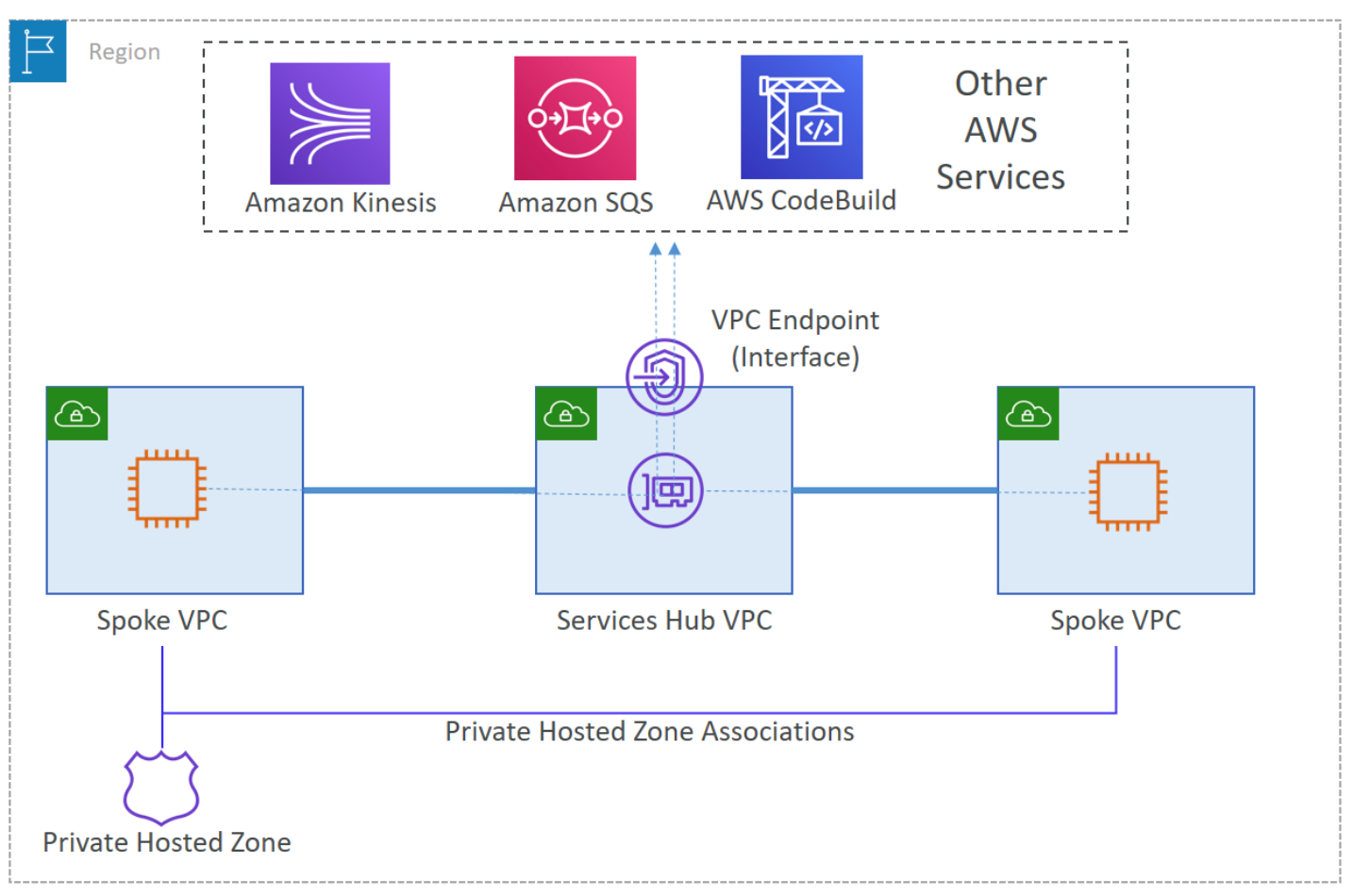
Deploy AWS VPC interface endpoints for AWS KMS and Secrets Manager inside shared-services-vpc-A and shared-services-vpc-B.
Use the AWS default DNS name for AWS KMS and Secrets Manager to create an Amazon Route 53 private hosted zone (PHZ) for each of these services. These are:
Authorize each spoke VPC to associate with the PHZ in their respective region. This can be done from the AWS Command Line Interface (AWS CLI) by using the command aws route53 create-vpc-association-authorization –hosted-zone-id <hosted-zone-id> –vpc VPCRegion=<region>,VPCId=<vpc-id> –region <AWS-REGION>.
Create an A record for each PHZ. In the creation process, for the Route to option, select the VPC Endpoint Alias. Add the respective VPC interface endpoint DNS hostname that is not Availability Zone specific (for example, vpce-0073b71485b9ad255-mu7cd69m.ssm.ap-south-1.vpce.amazonaws.com).
Associate each spoke VPC with the available PHZs. Use the CLI command aws route53 associate-vpc-with-hosted-zone –hosted-zone-id <hosted-zone-id> –vpc VPCRegion=<region>,VPCId=<vpc-id> –region <AWS-REGION>.
This concludes the configuration for centralized VPC interface endpoints for AWS KMS and Secrets Manager. You can learn more about cross-account PHZ association configuration.
After successfully implementing centralized VPC interface endpoints, the customer has decided to centralize:
Internet access.
Packet inspection for East-West and North-South internet traffic using a pair of firewalls that support the Geneve protocol.
Figure 8. Illustrated security-egress VPC infrastructures and route table configuration
To accomplish these centralization requirements, the customer should create:
A VPC with the name security-egress VPC.
A GWLB, an autoscaling group with at least two instance of the customer’s firewall which are evenly distributed across multiple private subnets in different Availability Zones.
A target group for use with the GWLB. Associate the autoscaling group with this target group.
An AWS endpoint service using the GWLB as the entry point. Then create AWS interface endpoints for this endpoint service inside the same set of private subnets or create a /28 set of subnets for interface endpoints.
Two AWS NAT gateways spread across two public subnets in multiple Availability Zones.
A transit gateway attachment request from the security-egress VPC and ensure that:
Transit gateway appliance mode is enabled for this attachment as it ensures bidirectional traffic forwarding to the same transit gateway attachments.
Transit gateway–specific subnets are used to host the attachment interfaces.
In the security-egress VPC, configure the route tables accordingly.
Private subnet route table.
Add default route to the NAT gateway.
Add summarized routes with a next-hop of Transit Gateway for all networks you intend to route to that are connected to the Transit Gateway.
Public subnet route table.
Add default route to the internet gateway.
Add summarized routes with a next-hop of the GWLB endpoints you intend to route to for all private networks.
Transit Gateway configuration
Create a new transit gateway route table with the name transit-gateway-egress-route-table.
Propagate all spoke and shared services VPCs routes to it.
Associate the security-egress VPC with this route table.
Add a default route to the spoke-tgw-route-table and shared-services-tgw-route-table that points to the security-egress VPC attachment, and remove all VPC attachment routes respectively from both route tables.
Figure 9. Illustrated routing configuration for the transit gateway route tables and VPC route tables
Figure 10. Illustrated North-South traffic flow from spoke VPC to the internet
Figure 11. Illustrated East-West traffic flow between spoke VPC and shared services VPC
Conclusion
In this blog post, we went on a network architecture journey that started with a use case of routing domain isolation. This is a scenario most customers confront when getting started with Transit Gateway. Gradually, we built upon this use case and exponentially increased its complexity by exploring other real-world scenarios that customers confront when designing multiple region networks across multiple AWS accounts.
Regardless of the complexity, these use cases were accompanied by guidance that helps customers achieve a reduction in cost and complexity throughout their entire network on AWS.
When designing your networks, design for scale. Use AWS services that let you achieve scale without the complexity of managing the underlying infrastructure.
Also, simplify your network through the technique of centralizing repeatable resources. If more than one VPC requires access to the same resource, then find ways to centralize access to this resource which reduces the proliferation of these resources. DNS, packet inspection, and VPC interface endpoints are good examples of things that should be centralized.
Thank you for reading. Hopefully you found this blog post useful.
Field Notes provides hands-on technical guidance from AWS Solutions Architects, consultants, and technical account managers, based on their experiences in the field solving real-world business problems for customers.
Many AWS customers use multiple AWS accounts and Regions across different departments and applications within the same company. However, you might deploy services like Amazon QuickSight using a single-account approach to centralize users, data source access, and dashboard management. This post explores how you can use different Amazon Virtual Private Cloud (Amazon VPC) private connectivity features to connect QuickSight to Amazon RDS or Amazon Redshift deployed in a different AWS account or Region.
Prepare the QuickSight environment
To implement any of the options discussed in this post, you need QuickSight with an Enterprise Edition subscription. One of the differences between this edition and the Standard Edition is the ability to connect QuickSight to a VPC—through an Elastic Network Interface (ENI)—and keep network traffic private within the AWS network. In this section, we take you through creating a VPC and enabling a VPC connection for QuickSight. For the rest of this post, you use AWS CloudShell from the AWS Management Console to run AWS Command Line Interface (AWS CLI) commands.
Before you complete the following steps, make sure you have sufficient AWS Identity and Access Management (IAM) privileges associated with your IAM user or role to create VPC endpoints, security groups, route tables, and a VPC peering connection.
If you have Amazon RDS or Amazon Redshift in the same Region and your organization uses cross-account resource sharing for your VPC, you can skip the next steps and go to the section on VPC sharing.
If you already have a VPC and subnet you want to use, you can skip to step 3.
Create a VPC and a subnet in the Region where your QuickSight account is deployed. See the following code:
aws ec2 create-vpc \
    --cidr-block CIDR block different than where redshift and rds are deployed \
    --tag-specifications \
 'ResourceType=vpc,Tags=[{Key=Name,Value=QuicksightVPC}]
Create a subnet where QuickSight can deploy an ENI:
aws ec2 create-subnet \
    --vpc-id ID of the VPC you created above\
    --cidr-block subnet cidr block within your VPC range \
    --tag-specifications \
    'ResourceType=subnet,Tags=[{Key=Name,Value=QuicksightSubnet}]'
Create a security group and allow a self-reference for all TCP traffic from the VPC CIDR range:
aws ec2 create-security-group \
    --group-name QuicksightSG \
    --description "Quicksight security group" \
    --vpc-id ID of the VPC you created above \
    --tag-specifications 'ResourceType=security-group,Tags=[{Key=Name,Value=QuicksightSG}]'
Create a route table and associate it to the subnet you created:
aws ec2 create-route-table \
    --vpc-id ID of the VPC you created above \
    --tag-specifications 'ResourceType=route- \ table,Tags=[{Key=Name,Value=QuicksightRouteTable}]'
aws ec2 associate-route-table \
    --route-table-id id of route table created above \
    --subnet-id subnet id created above
Now you configure QuickSight to create a VPC connection in the subnet you just created.
Sign in to the QuickSight console with administrator privileges.
Choose your profile icon and choose Manage QuickSight.
On the Manage QuickSight console, in the left panel, choose Manage VPC Connections.
Choose Add VPC Connection.
Provide the VPC ID, subnet ID, and security group ID you created earlier.
You can leave DNS resolver endpoints empty unless you have a private DNS deployment in the VPC.
You have now enabled QuickSight to access a subnet in your VPC. The following diagram shows the infrastructure you deployed.
Set up the data source infrastructure
You can choose from multiple possible deployment models when connecting Amazon Redshift or Amazon RDS. In the following sections, we walk you through how you can achieve each solution and when to use each one. For the rest of this post, we refer to Amazon Redshift and Amazon RDS as the data source.
VPC peering
A VPC peering connection is a networking connection between two VPCs that enables you to route traffic between them using private addresses. Instances in either VPC can communicate with each other as if they’re within the same network. This model is suitable for when the two accounts aren’t in the same AWS Organizations organization or Region, or are in the same organization but there is no AWS Transit Gateway attachment to the data source VPC. In this section, we create a network path between the QuickSight VPC and the data source VPC.
Create a VPC peering between the two VPCs. For instructions, see Creating and accepting a VPC peering connection. To use the hostname of the data source, you need to enable the DNS resolution for the peering connection at the requester and accepter of the peering connection. The DNS resolution must also be enabled at bot VPCs for this to work.
Run the following commands to enable the DNS resolution (depending on which account or Region the peering connection is initiated in, you need to run one command in the requester account or Region and the other in the accepter account or Region)
aws ec2 modify-vpc-peering-connection-options \
    --vpc-peering-connection-id your peering connection id \
    --accepter-peering-connection-options \
'{"AllowDnsResolutionFromRemoteVpc":true}'
aws ec2 modify-vpc-peering-connection-options \
    --vpc-peering-connection-id your peering connection id \
    --requester-peering-connection-options \
'{"AllowDnsResolutionFromRemoteVpc":true}'
Update the route tables in both the QuickSight VPC and data source VPC to route network traffic between them:
aws ec2 create-route \
    --route-table-id amazon quicksight subnet route table id\
    --destination-cidr-block data source vpc cidr \
    --vpc-peering-connection-id the id of the peering you created above
aws ec2 create-route \
    --route-table-id data source subnet route table id\
    --destination-cidr-block quicksight vpc cidr \
    --vpc-peering-connection-id the id of the peering you created above
Finally, you update the security groups for both QuickSight and the data source to allow traffic. If both VPCs are in the same Region, you can reference the security group instead of the CIDR of either data source or the QuickSight subnet.
In the QuickSight AWS account, run the following command:
In the data source AWS account, run the following command:
aws ec2 authorize-security-group-ingress \
    --group-id data source security group \
    --ip-permissions \
IpProtocol=tcp,FromPort=0,ToPort=65535,IpRanges=[{CidrIp=quicksight subnet CIDR}]
You have now created and configured a network path between QuickSight and your data source. The following diagram shows the infrastructure you deployed.
You can skip the next sections and proceed to connecting QuickSight to the data source.
AWS Transit Gateway
Transit Gateway connects VPCs through a central hub. It’s usually used in large deployments because it simplifies your network and reduces complex peering relationships. The transit gateway acts as a cloud router—each new connection is only made one time. A deployment model for the VPC of QuickSight with Transit Gateway is suitable when your network or infrastructure team has a policy on limiting VPC peering connections and enforces all new connections between VPCs through the transit gateway.
The Transit Gateway deployment model only works if the two AWS accounts are in the same organization and Region. This method also works if you have two transit gateway in different region that are peered.
Complete the following steps to create a network path between the QuickSight VPC and the data source VPC:
Run the following command to attach the QuickSight VPC to the shared transit gateway:
aws ec2 create-transit-gateway-vpc-attachment \
    --transit-gateway-id transit gateway id \
    --vpc-id quicksight vpc id \
    --subnet-id quicksight subnet id \
    --options {"DnsSupport": "enable"}
Run the following commands to accept the transit gateway attachment you created:
aws ec2 accept-transit-gateway-vpc-attachment \
    --transit-gateway-attachment-id your transit gateway attachment id
Now you need to update the transit gateway attachment with same route table that is used by the data source VPC transit gateway attachment.
Get the route table ID (TransitGatewayRouteTableId) with the following command:
aws ec2 describe-transit-gateway-attachments \
    --transit-gateway-attachment-ids your transit gateway id
Run the following command to attach the route table to the transit gateway attachment of QuickSight:
aws ec2 associate-transit-gateway-route-table \
    --transit-gateway-route-table-id your transit gateway id \
    --transit-gateway-attachment-id your transit gateway attachment id
Lastly, we update the security groups for both QuickSight and the data source to allow traffic.
In the AWS account where QuickSight is deployed, run the following command:
In the AWS account where the data source is deployed, run the following command:
aws ec2 authorize-security-group-ingress \
    --group-id data source security group \
    --ip-permissions \
IpProtocol=tcp,FromPort=0,ToPort=65535,IpRanges=[{CidrIp=quicksight subnet CIDR}]
You have now created and configured a network path between QuickSight and your data source. The following diagram shows the infrastructure you deployed.
You can skip the next sections and proceed to connecting QuickSight to the data source.
AWS PrivateLink
AWS PrivateLink provides private connectivity between VPCs, AWS services, and your on-premises networks. It simplifies your network architecture and makes it easy to connect AWS services across different accounts and VPCs.
You can use AWS PrivateLink as a self-managed endpoint to connect two VPCs or as a managed VPC endpoint for some services like Amazon Redshift. With an Amazon Redshift-managed VPC endpoint, you can privately access your Amazon Redshift data warehouse in your VPC from your client applications in another VPC within the same AWS account or another AWS account.
A self-managed AWS PrivateLink deployment is a solution for cross-account access; however, I don’t discuss it in this post. The solution relies on the IP of the data source ENI, which may change, which causes the AWS PrivateLink endpoint to lose connectivity to the data source, because the AWS PrivateLink Network Load Balancer uses IP-as-a-target to refer to the data source. This results in QuickSight being unable to refresh the dashboards and reports until you update the AWS PrivateLink configuration with the new IP.
The following steps walk you through creating a network path—using an Amazon Redshift managed VPC endpoint—between the QuickSight VPC and the data source VPC. This method only works with the RA3-instance of Amazon Redshift and not the DS2 instances.
Set up an Amazon Redshift-managed VPC endpoint between the Amazon Redshift cluster VPC and QuickSight VPC. For instructions, see Connecting to Amazon Redshift using an interface VPC endpoint. Then you update the security groups for both QuickSight and Amazon Redshift to allow traffic.
In the AWS account where QuickSight is deployed, run the following command:
In the AWS account where the data source is deployed, run the following command:
aws ec2 authorize-security-group-ingress \
    --group-id data source security group \
    --ip-permissions \
IpProtocol=tcp,FromPort=0,ToPort=65535,IpRanges=[{CidrIp=quicksight subnet CIDR}]
You have now created and configured a network path between QuickSight and your Amazon Redshift cluster. The following diagram shows the infrastructure you deployed.
You can skip the next section and proceed to connecting QuickSight to the data source.
VPC sharing
VPC sharing allows multiple AWS accounts to create their application resources, such as Amazon Elastic Compute Cloud (Amazon EC2) or RDS instances, into a shared, centrally managed VPC. In this model, the account that owns the VPC where the data source is deployed (owner) shares one or more subnets with other accounts (participants) that belong to the same organization. After a subnet is shared, the participants can use QuickSight to create the VPC connection in a subnet shared with them. Participants can’t view, modify, or delete resources that belong to other participants or the VPC owner.
This model is the most cost-effective because there’s no underlying cost for VPC peering, Transit Gateway, or AWS PrivateLink. It also simplifies network topologies and reduces the number of VPCs that you create and manage, while using separate accounts for billing and access control for each service used.
The following steps walk you through creating a VPC share and deploying a QuickSight ENI in the VPC to connect to the data source.
Share the data source VPC with the AWS account where QuickSight is deployed. For instructions, see Work with shared VPCs.
You have now created and configured a network path between QuickSight and your data source. The following diagram shows the infrastructure you deployed.
You can now connect QuickSight to the data source.
Connect QuickSight to the data source
Now that you have established the network link and configured both QuickSight and the data source to accept incoming and outgoing network traffic, you set up QuickSight to connect to the data source.
On the QuickSight console, choose Datasets in the navigation pane.
Choose Add a dataset.
Choose your database engine (such as PostgreSQL, MySQL or Redshift Manual connect). Do not choose Amazon RDS or Amazon Redshift auto-discover.
For Connection type, choose the VPC connection you created.
Provide the necessary information about your database server.
Choose Validate connection button to make sure QuickSight can connect to the data source.
Choose Create data source.
Choose the database you want to use and select the table.
You’re now ready to build your dashboards and reports.
Clean up
After following these steps, you should have successfully connected QuickSight to your data source. To avoid incurring any extra charges from the VPC configurations you made and depending on the use case you followed, you should delete the VPC peering, AWS PrivateLink endpoint, or transit gateway attachment.
Conclusion
In this post, we walked through reference access patterns that connect QuickSight to either Amazon RDS or Amazon Redshift running either on a different account, Region, or both. These methods aren’t limited to Amazon RDS or Amazon Redshift; you can use them with any database engine that is self-managed on Amazon EC2 and supported by QuickSight.
The following table summarizes the different deployment models and the preferred way to connect QuickSight to the data source.
Same Region
Different Region
Data Source
Data Source
Amazon Redshift RA3
Amazon RDS or Amazon Redshift DC2
Amazon Redshift RA3
Amazon RDS or Amazon Redshift DC2
Different AWS accounts same AWS organization
Amazon Redshift managed VPC endpoint or VPC sharing
After you set up your various data sources, you can join your data across various sources. You can also use these new data sources to gain further insights from your data by setting up ML Insights in QuickSight and setting graphical representations of your data using QuickSight visuals.
About the author
LotfiMouhib is a Senior Solutions Architect working for the Public Sector team with Amazon Web Services. He helps public sector customers across EMEA realize their ideas, build new services, and innovate for citizens. In his spare time, Lotfi enjoys cycling and running.
One of the best practices for building resilient systems in Amazon Virtual Private Cloud (VPC) networks is using multiple Availability Zones (AZ). An AZ is one or more discrete data centers with redundant power, networking, and connectivity. Using multiple AZs allows you to operate workloads that are more highly available, fault tolerant, and scalable than would be possible from a single data center. However, transferring data across AZs adds latency and cost.
This blog post demonstrates an architectural pattern called “Availability Zone Affinity” that improves performance and reduces costs while still maintaining the benefits of Multi-AZ architectures.
Cross Availability Zone effects
AZs are physically separated by a meaningful distance from other AZs in the same AWS Region. Although they all are within 60 miles (100 kilometers) of each other. This produces roundtrip latencies usually under 1-2 milliseconds (ms) between AZs in the same Region. Roundtrip latency between two instances in the same AZ is closer to 100-300 microseconds (µs) when using enhanced networking.1 This can be even lower when the instances use cluster placement groups. Additionally, when data is transferred between two AZs, data transfer charges apply in both directions.
To better understand these effects, we’ll analyze a fictitious workload, the “foo service,” shown in Figure 1. The foo service provides a storage platform for other workloads in AWS to redundantly store data. Requests are first processed by an Application Load Balancer (ALB). ALBs always use cross-zone load balancing to evenly distribute requests to all targets. Next, the request is sent from the load balancer to a request router. The request router performs a few operations, like authorization checks and input validation, before sending it to the storage tier. The storage tier replicates the data sequentially from the lead node, to the middle node, and finally the tail node. Once the data has been written to all three nodes, it is considered committed. The response is sent from the tail node back to the request router, back through the load balancer, and finally returned to the client.
Figure 1. An example system that transfers data across AZs
We can see in Figure 1 that, in the worst case, the request traversed an AZ boundary eight times. Let’s calculate the fastest possible, zeroth percentile (p0), latency. We’ll assume the best time for non-network processing of the request in the load balancer, request router, and storage tier is 4 ms. If we consider 1 ms as the minimum network latency added for each AZ traversal, in the worst-case scenario of eight AZ traversals, the total processing time can be no faster than 12 ms. At the 50th percentile (p50), meaning the median, let’s assume the cross-AZ latency is 1.5 ms and non-network processing is 8 ms, resulting in a total of 20 ms for overall processing. Additionally, if this system is processing millions of requests, the data transfer charges could become substantial over time. Now, let’s imagine that a workload using the foo service must operate with p50 latency under 20 ms. How can the foo service change their system design to meet this goal?
Availability Zone affinity
The AZ Affinity architectural pattern reduces the number of times an AZ boundary is crossed. In the example system we looked at in Figure 1, AZ Affinity can be implemented with two changes.
First, the ALB is replaced with a Network Load Balancer (NLB). NLBs provide an elastic network interface per AZ that is configured with a static IP. NLBs also have cross-zone load balancing disabled by default. This ensures that requests are only sent to targets that are in the same AZ as the elastic network interface that receives the request.
Second, DNS entries are created for each elastic network interface to provide an AZ-specific record using the AZ ID, which is consistent across accounts. Clients use that DNS record to communicate with a load balancer in the AZ they select. So instead of interacting with a Region-wide service using a DNS name like foo.com, they would instead use use1-az1.foo.com.
Figure 2 shows the system with AZ Affinity. We can see that each request, in the worst case, only traverses an AZ boundary four times. Data transfer costs are reduced by approximately 40 percent compared to the previous implementation. If we use 300 μs as the p50 latency for intra-AZ communication, we now get (4×300μs)+(4×1.5ms)=7.2ms. Using the median 8 ms processing time, this brings the overall median latency to 15.2 ms. This represents a 40 percent reduction in median network latency. When thinking about p90, p99, or even p99.9 latencies, this reduction could be even more significant.
Figure 2. The system now implements AZ Affinity
Figure 3 shows how you could take this approach one step farther using service discovery. Instead of requiring the client to remember AZ-specific DNS names for load balancers, we can use AWS Cloud Map for service discovery. AWS Cloud Map is a fully managed service that allows clients to look up IP address and port combinations of service instances using DNS and dynamically retrieve abstract endpoints, like URLs, over the HTTP-based service Discovery API. Service discovery can reduce the need for load balancers, removing their cost and added latency.
The client first retrieves details about the service instances in their AZ from the AWS Cloud Map registry. The results are filtered to the client’s AZ by specifying an optional parameter in the request. Then they use that information to send requests to the discovered request routers.
Figure 3. AZ Affinity implemented using AWS Cloud Map for service discovery
Workload resiliency
In the new architecture using AZ Affinity, the client has to select which AZ they communicate with. Since they are “pinned” to a single AZ and not load balanced across multiple AZs, they may see impact during an event affecting the AWS infrastructure or foo service in that AZ.
During this kind of event, clients can choose to use retries with exponential backoff or send requests to the other AZs that aren’t impacted. Alternatively, they could implement a circuit breaker to stop making requests from the client in the affected AZ and only use clients in the others. Both approaches allow them to use the resiliency of Multi-AZ systems while taking advantage of AZ Affinity during normal operation.
Client libraries
The easiest way to achieve the process of service discovery, retries with exponential backoff, circuit breakers, and failover is to provide a client library/SDK. The library handles all of this logic for users and makes the process transparent, like what the AWS SDK or CLI does. Users then get two options, the low-level API and the high-level library.
Conclusion
This blog demonstrated how the AZ Affinity pattern helps reduce latency and data transfer costs for Multi-AZ systems while providing high availability. If you want to investigate your data transfer costs, check out the Using AWS Cost Explorer to analyze data transfer costs blog for an approach using AWS Cost Explorer.
For investigating latency in your workload, consider using AWS X-Ray and Amazon CloudWatch for tracing and observability in your system. AZ Affinity isn’t the right solution for every workload, but if you need to reduce inter-AZ data transfer costs or improve latency, it’s definitely an approach to consider.
This estimate was made using t4g.small instances sending ping requests across AZs. The tests were conducted in the us-east-1, us-west-2, and eu-west-1 Regions. These results represent the p0 (fastest) and p50 (median) intra-AZ latency in those Regions at the time they were gathered, but are not a guarantee of the latency between two instances in any location. You should perform your own tests to calculate the performance enhancements AZ Affinity offers.
Voice calling systems are prevalent and necessary to many businesses today. They are usually designed to provide a 24×7 helpline support across multiple domains and use cases. Reliability and availability of such systems are important for a good customer experience. The thoughtful design of a cost-optimized solution will allow your business to sustain the system into the future.
We address a scenario in which you are mandated to host the workload on a corporate data center (DC), and configure the backup site on Amazon Web Services (AWS). Since the primary objective of a backup site is disaster recovery (DR) management, this site is often referred to as a DR site.
Disaster Recovery on AWS
DR strategy defines the recovery objectives for downtime and data loss. The workload has a recovery time objective (RTO) and a recovery point objective (RPO). RTO is the maximum acceptable delay between the interruption of service and the restoration of service. RPO is the maximum acceptable amount of time since the last data recovery point. AWS defines four DR strategies in increasing order of complexity, and decreasing order of RTO and RPO. These are backup and restore, active/passive (pilot light or warm standby), or active/active.
Figure 1. Disaster recovery (DR) options
In our use case, the DR site on AWS must serve the user traffic with RPO and RTO in seconds. Warm standby is the optimal choice in this case. It is a scaled-down version of a fully functional environment, and is always running in the cloud.
Amazon Connect is an omnichannel cloud contact center that helps you provide great customer service at a lower cost. But in some situations, Amazon Connect may not be available. In other cases, the customer may want to use their home developed or third-party contact center application. Our solution is designed to help in both these scenarios.
This architecture enables customers facing challenges of cost overhead with redundant Session Initiation Protocol (SIP) trunks for the DC and DR sites. It allows you to optimize your spend and yet retain a reliable workflow.
SIP trunk communication on AWS
Let’s see how the SIP trunk termination on the AWS network handles the failover scenario of a third-party IVR application installed on Amazon EC2 at the DR site.
There will be two connections made from the AWS Direct Connect location (DX). The first will be for a point-to-point connectivity between the corporate DC and the AWS DR site. The second connection will be originating from the multiplexer (MUX) of the telecom provider who is providing you the SIP trunk.
The telecom provider will lay the SIP trunk from its MUX to the customer router at the DX location. At this point, the mode of communication becomes IP-based. The telecom provider will send the call to the IP address attached to the Network Load Balancer (NLB) in Amazon Virtual Private Cloud (VPC).
Figure 2. Communication circuitry at telecom side
AWS Network Load Balancers can now distribute traffic to AWS resources using their IP addresses and instance IDs as targets. You can also distribute the traffic with on-premises resources over AWS Direct Connect. Load balancing across AWS and on-premises resources using the same load balancer streamlines migrate-to-cloud, burst-to-cloud, or failover-to-cloud.
In the backup site, the NLB will point to the Session Border Controller (SBC). This is a special-purpose device that protects and regulates IP communications flows. You can bring your own SBC, or you can use an SBC offered in the AWS Marketplace.
Best practices for high availability of IVR solution on AWS
Configure the multiple Availability Zone (Multi-AZ) SBC setup
Make sure that the telecom provider for the SIP trunk is different from the internet service provider (ISP). This is for last mile connectivity for the DC from Direct Connect
Consider redundancy for Direct Connect by using a Site-to-Site VPN tunnel
Figure 3. Solution architecture of DR on AWS for a third-party IVR solution
Communication flow for an IVR solution deployed on a corporate DC and its DR on AWS
The callers are received on the telecom providers SIP line, which terminates on the AWS Direct Connect location.
At the DX location, you will configure a route in the AWS router to send the traffic to the IP address of the NLB. The NLB should be configured to perform health checks on the virtual machine in your on-premises DC. Based on these health checks, the NLB will do the routing and the failover.
In a live scenario with successful health checks at the DC, the NLB will forward the call to the IP of the on-premises virtual machine. This is where the IVR application will be installed.
The communication between the NLB in Amazon VPC and the virtual machine in DC, will happen over Direct Connect.
In a DR scenario, the NLB will failover the communication to SBCs in Amazon VPC.
Conclusion
This solution is useful when a third-party IVR system is deployed in a corporate data center, and the passive DR site is hosted on AWS. Cost optimization on telecom components is an important aspect of this design. AWS Direct Connect provides dedicated connectivity to the AWS environment, from 50 Mbps up to 10 Gbps. This gives you managed and controlled latency. It also provides provisioned bandwidth, so your workload can connect to AWS resources in a reliable, scalable, and cost-effective way.
The solution in this blog explains the end-to-end flow of communication, from the user to the IVR agents. It also provides insights into managing failover and failback between DR and the DR site.
This post was co-written by Akshay Panchmukh, Product Manager, Druva and Girish Chanchlani, Sr Partner Solutions Architect, AWS.
The Uptime Institute’s Annual Outage Analysis 2021 report estimated that 40% of outages or service interruptions in businesses cost between $100,000 and $1 million, while about 17% cost more than $1 million. To guard against this, it is critical for you to have a sound data protection and disaster recovery (DR) strategy to minimize the impact on your business. With the greater adoption of the public cloud, most companies are either following a hybrid model with critical workloads spread across on-premises data centers and the cloud or are all in the cloud.
In this blog post, we focus on how Druva, a SaaS based data protection solution provider, can help you implement a DR strategy for your workloads running in Amazon Web Services (AWS). We explain how to set up protection of AWS workloads running in one AWS account, and fail them over to another AWS account or Region, thereby minimizing the impact of disruption to your business.
Overview of the architecture
In the following architecture, we describe how you can protect your AWS workloads from outages and disasters. You can quickly set up a DR plan using Druva’s simple and intuitive user interface, and within minutes you are ready to protect your AWS infrastructure.
Figure 1. Druva architecture
Druva’s cloud DR is built on AWS using native services to provide a secure operating environment for comprehensive backup and DR operations. With Druva, you can:
Seamlessly create cross-account DR sites based on source sites by cloning Amazon Virtual Private Clouds (Amazon VPCs) and their dependents.
Set up backup policies to automatically create and copy snapshots of Amazon Elastic Compute Cloud (Amazon EC2) and Amazon Relational Database Service (Amazon RDS) instances to DR Regions based on recovery point objective (RPO) requirements.
Set up service level objective (SLO) based DR plans with options to schedule automated tests of DR plans and ensure compliance.
Monitor implementation of DR plans easily from the Druva console.
Generate compliance reports for DR failover and test initiation.
Other notable features include support for automated runbook initiation, selection of target AWS instance types for DR, and simplified orchestration and testing to help protect and recover data at scale. Druva provides the flexibility to adopt evolving infrastructure across geographic locations, adhere to regulatory requirements (such as, GDPR and CCPA), and recover workloads quickly following disasters, helping meet your business-critical recovery time objectives (RTOs). This unified solution offers taking snapshots as frequently as every five minutes, improving RPOs. Because it is a software as a service (SaaS) solution, Druva helps lower costs by eliminating traditional administration and maintenance of storage hardware and software, upgrades, patches, and integrations.
We will show you how to set up Druva to protect your AWS workloads and automate DR.
Step 1: Log into the Druva platform and provide access to AWS accounts
After you sign into the Druva Cloud Platform, you will need to grant Druva third-party access to your AWS account by pressing Add New Account button, and following the steps as shown in Figure 2.
Figure 2. Add AWS account information
Druva uses AWS Identity and Access Management (IAM) roles to access and manage your AWS workloads. To help you with this, Druva provides an AWS CloudFormation template to create a stack or stack set that generates the following:
IAM role
IAM instance profile
IAM policy
The generated Amazon Resource Name (ARN) of the IAM role is then linked to Druva so that it can run backup and DR jobs for your AWS workloads. Note that Druva follows all security protocols and best practices recommended by AWS. All access permissions to your AWS resources and Regions are controlled by IAM.
After you have logged into Druva and set up your account, you can now set up DR for your AWS workloads. The following steps will allow you to set up DR for AWS infrastructure.
Step 2: Identify the source environment
A source environment refers to a logical grouping of Amazon VPCs, subnets, security groups, and other infrastructure components required to run your application.
Figure 3. Create a source environment
In this step, create your source environment by selecting the appropriate AWS resources you’d like to set up for failover. Druva currently supports Amazon EC2 and Amazon RDS as sources that can be protected. With Druva’s automated DR, you can failover these resources to a secondary site with the press of a button.
Figure 4. Add resources to a source environment
Note that creating a source environment does not create or update existing resources or configurations in your AWS account. It only saves this configuration information with Druva’s service.
Step 3: Clone the environment
The next step is to clone the source environment to a Region where you want to failover in case of a disaster. Druva supports cloning the source environment to another Region or AWS account that you have selected. Cloning essentially replicates the source infrastructure in the target Region or account, which allows the resources to be failed over quickly and seamlessly.
Figure 5. Clone the source environment
Step 4: Set up a backup policy
You can create a new backup policy or use an existing backup policy to create backups in the cloned or target Region. This enables Druva to restore instances using the backup copies.
Figure 6. Create a new backup policy or use an existing backup policy
Figure 7. Customize the frequency of backup schedules
Step 5: Create the DR plan
A DR plan is a structured set of instructions designed to recover resources in the event of a failure or disaster. DR aims to get you back to the production-ready setup with minimal downtime. Follow these steps to create your DR plan.
Create DR Plan: Press Create Disaster Recovery Plan button to open the DR plan creation page.
Figure 8. Create a disaster recovery plan
Name: Enter the name of the DR plan. Service Level Objective (SLO): Enter your RPO and RTO.
Recovery Point Objective – Example: If you set your RPO as 24 hours, and your backup was scheduled daily at 8:00 PM, but a disaster occurred at 7:59 PM, you would be able to recover data that was backed up on the previous day at 8:00 PM. You would lose the data generated after the last backup (24 hours of data loss).
Recovery Time Objective – Example: If you set your RTO as 30 hours, when a disaster occurred, you would be able to recover all critical IT services within 30 hours from the point in time the disaster occurs.
Figure 9. Add your RTO and RPO requirements
Create your plan based off the source environment, target environment, and resources.
Environments
Source Account
By default, this is the Druva account in which you are currently creating the DR plan.
Source Environment
Select the source environment applicable within the Source Account (your Druva account in which you’re creating the DR plan).
Target Account
Select the same or a different target account.
Target Environment
Select the Target Environment, applicable within the Target Account.
Resources
Create Policy
If you do not have a backup policy, then you can create one.
Add Resources
Add resources from the source environment that you want to restore. Make sure the verification column shows a ‘Valid Backup Policy’ status. This ensures that the backup policy is frequently creating copies as per the RPO defined previously.
Figure 10. Create DR plan based off the source environment, target environment, and resources
Identify target instance type, test plan instance type, and run books for this DR plan.
Target Instance Type
Target Instance Type can be selected. If instance type is not selected then:
Select an instance type which is large in size.
Select an instance type which is smaller.
Fail the creation of the instance.
Test Plan Instance Type
There are many options. To reduce incurring cost, the lower instance type can be selected from all available AWS instance types.
Run Books
Select this option if you would like to shutdown the source server after failover occurs.
Figure 11. Identify target instance type, test plan instance type, and run books
Step 6: Test the DR plan
After you have defined your DR plan, it is time to test it so that you can—when necessary—initiate a failover of resources to the target Region. You can now easily try this on the resources in the cloned environment without affecting your production environment.
Figure 12. Test the DR plan
Testing your DR plan will help you to find answers for some of the questions like: How long did the recovery take? Did I meet my RTO and RPO objectives?
Step 7: Initiate the DR plan
After you have successfully tested the DR plan, it can easily be initiated with the click of a button to failover your resources from the source Region or account to the target Region or account.
Conclusion
With the growth of cloud-based services, businesses need to ensure that mission-critical applications that power their businesses are always available. Any loss of service has a direct impact on the bottom line, which makes business continuity planning a critical element to any organization. Druva offers a simple DR solution which will help you keep your business always available.
Druva provides unified backup and cloud DR with no need to manage hardware, software, or costs and complexity. It helps automate DR processes to ensure your teams are prepared for any potential disasters while meeting compliance and auditing requirements.
With Druva, you can easily validate your RTO and RPO with automated regular DR testing, cross-account DR for protection against attacks and accidental deletions, and ensure backups are isolated from your primary production account for DR planning. With cross-Region DR, you can duplicate the entire Amazon VPC environment across Regions to protect you against Regionwide failures. In conclusion, Druva is a complete solution built with a goal to protect your native AWS workloads from any disasters.
Field Notes provides hands-on technical guidance from AWS Solutions Architects, consultants, and technical account managers, based on their experiences in the field solving real-world business problems for customers.
Since December 2019, Amazon Virtual Private Cloud (VPC) has allowed you to route all ingress traffic (also known as north – south traffic) to a specific network interface. You might use this capability for a number of reasons. For example, to inspect incoming traffic using an intrusion detection system (IDS) appliance or to route ingress traffic to a firewall.
Since we launched this feature, many of you asked us to provide a similar capability to analyze traffic flowing from one subnet to another inside your VPC, also known as east – west traffic. Until today, it was not possible because a route in a routing table cannot be more specific than the default local route (check the VPC documentation for more details). In plain English, it means that no route can have a destination using a smaller CIDR range than the default local route (which is the CIDR range of the whole VPC). For example, when the VPC range is 10.0.0/16 and a subnet has 10.0.1.0/24, a route to 10.0.1.0/24 is more specific than a route to 10.0.0/16.
Routing tables no longer have this restriction. Routes in a routing table can have routes more specific than the default local route. You can use such more specific route to send all traffic to a dedicated appliance or service to inspect, analyze, or filter all traffic flowing between two subnets (east-west traffic). The route target can be the network interface (ENI) attached to an appliance you built or you acquired, an AWS Gateway Load Balancer (GWLB) endpoint to distribute traffic to multiple appliances for performance or high availability reasons, an AWS Firewall Manager endpoint, or a NAT gateway. It also allows to insert an appliance between a subnet and an AWS Transit Gateway.
It is possible to chain appliances to have more than one type of analysis in between source and destination subnets. For examples, you might want first to filter traffic using a firewall (AWS managed or a third-party firewall appliance), second send the traffic to an intrusion detection and prevention systems, and finally, perform deep packet inspection. You can access virtual appliances from our AWS Partner Network and AWS Marketplace.
When you chain appliances, each appliance and each endpoint have to be in separate subnets.
Let’s get our hands dirty and try this new capability.
How It Works For the purpose of this blog post, let’s assume I have a VPC with three subnets. The first subnet is public and has a bastion host. It requires access to resources, such as an API or a database in the second subnet. The second subnet is private. It hosts the resources required by the bastion. I wrote a simple CDK script to help you to deploy this setup.
For compliance reasons, my company requires that traffic to this private application flows through an intrusion detection system. The CDK script also creates a third subnet, a private one, to host a network appliance. It provides three Amazon Elastic Compute Cloud (Amazon EC2) instances : the bastion host, the application instance and the network analysis appliance. The script also creates a NAT gateway allowing to bootstrap the application instance and to connect to the three instances using AWS Systems Manager Session Manager (SSM).
Because this is a demo, the network appliance is just a regular Amazon Linux EC2 instance configured as an IP router. In real life, you’re most probably going to use either one of the many appliances provided by our partners on the AWS Marketplace, or a Gateway Load Balancer endpoint, or a Network Firewall.
Let’s modify the routing tables to send the traffic through the appliance.
Using either the AWS Management Console, or the AWS Command Line Interface (CLI), I add a more specific route to the 10.0.0.0/24 and 10.0.1.0/24 subnet routing tables. These routes point to eni0, the network interface of the traffic-inspection appliance.
Using the CLI, I first collect the VPC ID, Subnet IDs, routing table IDs, and the ENI ID of the appliance.
Next, I add two more specific routes. One route sends traffic from the bastion public subnet to the application private subnet through the appliance network interface. The second route is in the opposite direction to route replies. It routes more specific traffic from the application private subnet to the bastion public subnet through the appliance network interface. Confused? Let’s look at the following diagram:
I can also use the Amazon VPC Console to make these modifications. I simply choose the “Bastion” routing tables and from the Routes tab and click Edit routes.
I add a route to send traffic for 10.0.1.0/24 (subnet of the application) to the appliance ENI (eni-055...).
The next step is to define the opposite route for replies, from the application subnet send traffic to 10.0.0.0/24 to the appliance ENI (eni-05...). Once finished, the application subnet routing table should look like this:
Configure the Appliance Instance Finally, I configure the appliance instance to forward all traffic it receives. Your software appliance usually does that for you. No extra step is required when you use AWS Marketplace appliances or the instance created by the CDK script I provided for this demo. If you’re using a plain Linux instance, complete these two extra steps:
1. Connect to the EC2 appliance instance and configure IP traffic forwarding in the kernel:
After you’re connected to the bastion host, issue the following cURL command to connect to the application host:
sh-4.2$ curl -I 10.0.1.239 # use the private IP address of your application host
HTTP/1.1 200 OK
Server: nginx/1.18.0
Date: Mon, 24 May 2021 10:00:22 GMT
Content-Type: text/html
Content-Length: 12338
Last-Modified: Mon, 24 May 2021 09:36:49 GMT
Connection: keep-alive
ETag: "60ab73b1-3032"
Accept-Ranges: bytes
To verify the traffic is really flowing through the appliance, you can enable source/destination check on the instance again. Use the --source-dest-check parameter with the modify-instance-attribute CLI command above. The traffic is blocked when the source/destination check is enabled.
I can also connect to the appliance host and inspect traffic with the tcpdump command.
(on your laptop)
APPLIANCE_ID=$(aws --region $REGION ec2 describe-instances     \
                   --filter "Name=tag:Name,Values=appliance" \
		   --query "Reservations[].Instances[?State.Name == 'running'].InstanceId[]" \
  		   --output text)

aws --region $REGION ssm start-session --target $APPLIANCE_ID

(on the appliance host)
tcpdump -i eth0 host 10.0.0.16 # the private IP address of the bastion host

08:53:22.760055 IP ip-10-0-0-16.us-west-2.compute.internal.46934 > ip-10-0-1-104.us-west-2.compute.internal.http: Flags [S], seq 1077227105, win 26883, options [mss 8961,sackOK,TS val 1954932042 ecr 0,nop,wscale 6], length 0
08:53:22.760073 IP ip-10-0-0-16.us-west-2.compute.internal.46934 > ip-10-0-1-104.us-west-2.compute.internal.http: Flags [S], seq 1077227105, win 26883, options [mss 8961,sackOK,TS val 1954932042 ecr 0,nop,wscale 6], length 0
08:53:22.760322 IP ip-10-0-1-104.us-west-2.compute.internal.http > ip-10-0-0-16.us-west-2.compute.internal.46934: Flags [S.], seq 4152624111, ack 1077227106, win 26847, options [mss 8961,sackOK,TS val 4094021737 ecr 1954932042,nop,wscale 6], length 0
08:53:22.760329 IP ip-10-0-1-104.us-west-2.compute.internal.http > ip-10-0-0-16.us-west-2.compute.internal.46934: Flags [S.], seq 4152624111, ack 1077227106, win 26847, options [mss
Cleanup If you used the CDK script I provided for this post, be sure to run cdk destroy when you’re finished so that you’re not billed for the three EC2 instances and the NAT gateway I use for this demo. Running the demo script in us-west-2costs $0.062 per hour.
Things to Keep in Mind. There are couple of things to keep in mind when using VPC more specific routes :
The network interface or service endpoint you are sending the traffic to must be in a dedicated subnet. It cannot be in the source or destination subnet of your traffic.
You can chain appliances. Each appliance must live in its dedicated subnet.
Each subnet you’re adding consumes a block of IP addresses. If you’re using IPv4, be conscious of the number of IP addresses consumed (A /24 subnet consumes 256 addresses from your VPC). The smallest CIDR range allowed in a subnet is /28, it just consumes 16 IP addresses.
The appliance’s security group must have a rule accepting incoming traffic on the desired port. Similarly, the application’s security group must authorize traffic coming from the appliance security group or IP address.
This new capability is available in all AWS Regions, at no additional cost.
VMware Cloud on AWS allows you to quickly migrate VMware workloads to a VMware-managed Software-Defined Data Center (SDDC) running in the AWS Cloud and extend your on-premises data centers without replatforming or refactoring applications.
You can use native AWS services with Virtual Machines (VMs) in the SDDC, to reduce operational overhead and lower your Total Cost of Ownership (TCO) while increasing your workload’s agility and scalability.
This post covers patterns for connectivity between native AWS services and VMware workloads. We also explore common integrations, including using AWS Cloud storage from an SDDC, securing VM workloads using AWS networking services, and using AWS databases and analytics services with workloads running in the SDDC.
Networking between SDDC and native AWS services
Establishing robust network connectivity with VMware Cloud SDDC VMs is critical to successfully integrating AWS services. This section shows you different options to connect the VMware SDDC with your native AWS account.
The simplest way to get started is to use AWS services in the connected Amazon Virtual Private Cloud (VPC) that is selected during the SDDC deployment process. Figure 1 shows this connectivity, which is automatically configured and available once the SDDC is deployed.
Figure 1. SDDC to Customer Account VPC connectivity configured at deployment
The SDDC Elastic Network Interface (ENI) allows you to connect to native AWS services within the connected VPC, but it doesn’t provide transitive routing beyond the connected VPC. For example, it will not connect the SDDC to other VPCs and the internet.
If you’re looking to connect to native AWS services in multiple accounts and VPCs in the same AWS Region, you have two connectivity options. These are explained in the following sections.
Attaching VPCs to VMware Transit Connect
When you need high-throughput connectivity in a multi-VPC environment, use VMware Transit Connect (VTGW), as shown in Figure 2.
VTGW uses a VMware-managed AWS Transit Gateway to interconnect SDDCs within an SDDC group. It also allows you to attach your VPCs in the same Region to the VTGW by providing connectivity to any SDDC within the SDDC group.
Connecting through an AWS Transit Gateway
To connect to your VPCs through an existing Transit Gateway in your account, use IPsec virtual private network (VPN) connections from the SDDC with Border Gateway Protocol (BGP)-based routing, as shown in Figure 3. Multiple IPsec tunnels to the Transit Gateway use equal-cost multi-path routing, which increases bandwidth by load-balancing traffic.
Figure 3. Multi-account VPC connectivity through an AWS Transit Gateway
For scalable, high throughput connectivity to an existing Transit Gateway, connect to the SDDC via a Transit VPC that is attached to the VTGW, as shown in Figure 3. You must manually configure the routes between the VPCs and SDDC for this architecture.
In the following sections, we’ll show you how to use some of these connectivity options for common native AWS services integrations with VMware SDDC workloads.
Reducing TCO with Amazon EFS, Amazon FSx, and Amazon S3
Additionally, you can reduce the undifferentiated heavy lifting involved with deploying and managing complex architectures for file services in VM disks. Figure 4 shows how these services integrate with VMs in the SDDC.
Figure 4. Connectivity examples for AWS Cloud storage services
We recommend connecting to your S3 buckets via the VPC gateway endpoint in the connected VPC. This is a more cost-effective approach because it avoids the data processing costs associated with a VTGW and AWS PrivateLink for Amazon S3.
Similarly, the recommended approach for Amazon EFS and Amazon FSx is to deploy the services in the connected VPC for VM access through the SDDC elastic network interface. You can also connect to existing Amazon EFS and Amazon FSx file shares in other accounts and VPCs using a VTGW, but consider the data transfer costs first.
Integrating AWS networking and content delivery services
Using various AWS networking and content delivery services with VMware Cloud on AWS workloads will provide robust traffic management, security, and fast content delivery. Figure 5 shows how AWS networking and content delivery services integrate with workloads running on VMs.
Figure 5. Connectivity examples for AWS networking and content delivery services
Deploy Elastic Load Balancing (ELB) services in a VPC subnet that has network reachability to the SDDC VMs. This includes the connected VPC over the SDDC elastic network interface, a VPC attached via VTGW, and VPCs attached to a Transit Gateway connected to the SDDC.
VTGW connectivity should be used when the design requires using existing networking services in other VPCs. For example, if you have a dedicated internet ingress/egress VPC. An internal ELB can also be used for load-balancing traffic between services running in SDDC VMs and services running within AWS VPCs.
Integrating with AWS database and analytics services
Data is one the most valuable assets in an organization, and databases are often the most demanding and critical workloads running in on-premises VMware environments.
A common customer pattern to reduce TCO for storage-heavy or memory-intensive databases is to use purpose-built Databases on AWS like Amazon Relational Database Service (RDS). Amazon RDS lets you migrate on-premises relational databases to the cloud and integrate it with SDDC VMs. Using AWS databases also reduces operational overhead you may incur with tasks associated with managing availability, scalability, and disaster recovery (DR).
With AWS Analytics services integrations, you can take advantage of the close proximity of data within VMware Cloud on AWS data stores to gain meaningful insights from your business data. For example, you can use Amazon Redshift to create a data warehouse to run analytics at scale on relational data from transactional systems, operational databases, and line-of-business applications running within the SDDC.
Figure 6 shows integration options for AWS databases and analytics services with VMware Cloud on AWS VMs.
Figure 6. Connectivity examples for AWS Database and Analytics services
We recommend deploying and consuming database services in the connected VPC. If you have existing databases in other accounts or VPCs that require integration with VMware VMs, connect them using the VTGW.
Analytics services can involve ingesting large amounts of data from various sources, including from VMs within the SDDC, creating a significant amount of data traffic. In such scenarios, we recommend using the SDDC connected VPC to deploy any required interface endpoints for analytics services to achieve a cost-effective architecture.
Summary
VMware Cloud on AWS is one of the fastest ways to migrate on-premises VMware workloads to the cloud. In this blog post, we provided different architecture options for connecting the SDDC to native AWS services. This lets you evaluate your requirements to select the most cost-effective option for your workload.
The example integrations covered in this post are common AWS service integrations, including storage, network, and databases. They are a great starting point, but the possibilities are endless. Integrating services like Amazon Machine Learning (Amazon ML), and Serverless on AWS allows you to deliver innovative services to your users, often without having to re-factor existing application backends running on VMware Cloud on AWS.
Additional Resources
If you need to integrate VMware Cloud on AWS with an AWS service, explore the following resources and reach out to us at AWS.
This series of blog posts uses the AWS Well-Architected Tool with the Serverless Lens to help customers build and operate applications using best practices. In each post, I address the serverless-specific questions identified by the Serverless Lens along with the recommended best practices. See the introduction post for a table of contents and explanation of the example application.
PERF 1. Optimizing your serverless application’s performance
This post continues part 1 of this security question. Previously, I cover measuring and optimizing function startup time. I explain cold and warm starts and how to reuse the Lambda execution environment to improve performance. I show a number of ways to analyze and optimize the initialization startup time. I explain how only importing necessary libraries and dependencies increases application performance.
Good practice: Design your function to take advantage of concurrency via asynchronous and stream-based invocations
AWS Lambda functions can be invoked synchronously and asynchronously.
Favor asynchronous over synchronous request-response processing.
Consider using asynchronous event processing rather than synchronous request-response processing. You can use asynchronous processing to aggregate queues, streams, or events for more efficient processing time per invocation. This reduces wait times and latency from requesting apps and functions.
When you invoke a Lambda function with a synchronous invocation, you wait for the function to process the event and return a response.
Synchronous invocation
As synchronous processing involves a request-response pattern, the client caller also needs to wait for a response from a downstream service. If the downstream service then needs to call another service, you end up chaining calls that can impact service reliability, in addition to response times. For example, this POST /order request must wait for the response to the POST /invoice request before responding to the client caller.
Example synchronous processing
The more services you integrate, the longer the response time, and you can no longer sustain complex workflows using synchronous transactions.
Asynchronous processing allows you to decouple the request-response using events without waiting for a response from the function code. This allows you to perform background processing without requiring the client to wait for a response, improving client performance. You pass the event to an internal Lambda queue for processing and Lambda handles the rest. An external process, separate from the function, manages polling and retries. Using this asynchronous approach can also make it easier to handle unpredictable traffic with significant volumes.
Asynchronous invocation
For example, the client makes a POST /order request to the order service. The order service accepts the request and returns that it has been received, without waiting for the invoice service. The order service then makes an asynchronous POST /invoice request to the invoice service, which can then process independently of the order service. If the client must receive data from the invoice service, it can handle this separately via a GET /invoice request.
Example asynchronous processing
You can configure Lambda to send records of asynchronous invocations to another destination service. This helps you to troubleshoot your invocations. You can also send messages or events that can’t be processed correctly into a dedicated Amazon Simple Queue Service (SQS) dead-letter queue for investigation.
You can add triggers to a function to process data automatically. For more information on which processing model Lambda uses for triggers, see “Using AWS Lambda with other services”.
Asynchronous workflows handle a variety of use cases including data Ingestion, ETL operations, and order/request fulfillment. In these use-cases, data is processed as it arrives and is retrieved as it changes. For example asynchronous patterns, see “Serverless Data Processing” and “Serverless Event Submission with Status Updates”.
Tune batch size, batch window, and compress payloads for high throughput
When using Lambda to process records using Amazon Kinesis Data Streams or SQS, there are a number of tuning parameters to consider for performance.
You can configure a batch window to buffer messages or records for up to 5 minutes. You can set a limit of the maximum number of records Lambda can process by setting a batch size. Your Lambda function is invoked whichever comes first.
For high volume SQS standard queue throughput, Lambda can process up to 1000 concurrent batches of records per second. For more information, see “Using AWS Lambda with Amazon SQS”.
For high volume Kinesis Data Streams throughput, there are a number of options. Configure the ParallelizationFactor setting to process one shard of a Kinesis Data Stream with more than one Lambda invocation simultaneously. Lambda can process up to 10 batches in each shard. For more information, see “New AWS Lambda scaling controls for Kinesis and DynamoDB event sources.” You can also add more shards to your data stream to increase the speed at which your function can process records. This increases the function concurrency at the expense of ordering per shard. For more details on using Kinesis and Lambda, see “Monitoring and troubleshooting serverless data analytics applications”.
Kinesis stream producers can also compress records. This is at the expense of additional CPU cycles for decompressing the records in your Lambda function code.
Required practice: Measure, evaluate, and select optimal capacity units
Capacity units are a unit of consumption for a service. They can include function memory size, number of stream shards, number of database reads/writes, request units, or type of API endpoint. Measure, evaluate and select capacity units to enable optimal configuration of performance, throughput, and cost.
Identify and implement optimal capacity units.
For Lambda functions, memory is the capacity unit for controlling the performance of a function. You can configure the amount of memory allocated to a Lambda function, between 128 MB and 10,240 MB. The amount of memory also determines the amount of virtual CPU available to a function. Adding more memory proportionally increases the amount of CPU, increasing the overall computational power available. If a function is CPU-, network- or memory-bound, then changing the memory setting can dramatically improve its performance.
Choosing the memory allocated to Lambda functions is an optimization process that balances performance (duration) and cost. You can manually run tests on functions by selecting different memory allocations and measuring the time taken to complete. Alternatively, use the AWS Lambda Power Tuning tool to automate the process.
The tool allows you to systematically test different memory size configurations and depending on your performance strategy – cost, performance, balanced – it identifies what is the most optimum memory size to use. For more information, see “Operating Lambda: Performance optimization – Part 2”.
AWS Lambda Power Tuning report
Amazon DynamoDB manages table processing throughput using read and write capacity units. There are two different capacity modes, on-demand and provisioned.
On-demand capacity mode supports up to 40K read/write request units per second. This is recommended for unpredictable application traffic and new tables with unknown workloads. For higher and predictable throughputs, provisioned capacity mode along with DynamoDB auto scaling is recommended. For more information, see “Read/Write Capacity Mode”.
For high throughput Amazon Kinesis Data Streams with multiple consumers, consider using enhanced fan-out for dedicated 2 MB/second throughput per consumer. When possible, use Kinesis Producer Library and Kinesis Client Library for effective record aggregation and de-aggregation.
Amazon API Gateway supports multiple endpoint types. Edge-optimized APIs provide a fully managed Amazon CloudFront distribution. These are better for geographically distributed clients. API requests are routed to the nearest CloudFront Point of Presence (POP), which typically improves connection time.
Edge-optimized API Gateway deployment
Regional API endpoints are intended when clients are in the same Region. This helps you to reduce request latency and allows you to add your own content delivery network if necessary.
AWS Step Functions has two workflow types, standard and express. Standard Workflows have exactly once workflow execution and can run for up to one year. Express Workflows have at-least-once workflow execution and can run for up to five minutes. Consider the per-second rates you require for both execution start rate and the state transition rate. For more information, see “Standard vs. Express Workflows”.
Performance load testing is recommended at both sustained and burst rates to evaluate the effect of tuning capacity units. Use Amazon CloudWatch service dashboards to analyze key performance metrics including load testing results. I cover performance testing in more detail in “Regulating inbound request rates – part 1”.
Evaluate and optimize your serverless application’s performance based on access patterns, scaling mechanisms, and native integrations. You can improve your overall experience and make more efficient use of the platform in terms of both value and resources.
This post continues from part 1 and looks at designing your function to take advantage of concurrency via asynchronous and stream-based invocations. I cover measuring, evaluating, and selecting optimal capacity units.
This well-architected question will continue in part 3 where I look at integrating with managed services directly over functions when possible. I cover optimizing access patterns and applying caching where applicable.
For more serverless learning resources, visit Serverless Land.
Fifteen years ago today I wrote the blog post that launched the Amazon EC2 Beta. As I recall, the launch was imminent for quite some time as we worked to finalize the feature set, the pricing model, and innumerable other details. The launch date was finally chosen and it happened to fall in the middle of a long-planned family vacation to Cabo San Lucas, Mexico. Undaunted, I brought my laptop along on vacation, and had to cover it with a towel so that I could see the screen as I wrote. I am not 100% sure, but I believe that I actually clicked Publish while sitting on a lounge chair near the pool! I spent the remainder of the week offline, totally unaware of just how much excitement had been created by this launch.
Preparing for the Launch When Andy Jassy formed the AWS group and began writing his narrative, he showed me a document that proposed the construction of something called the Amazon Execution Service and asked me if developers would find it useful, and if they would pay to use it. I read the document with great interest and responded with an enthusiastic “yes” to both of his questions. Earlier in my career I had built and run several projects hosted at various colo sites, and was all too familiar with the inflexible long-term commitments and the difficulties of scaling on demand; the proposed service would address both of these fundamental issues and make it easier for developers like me to address widely fluctuating changes in demand.
The EC2 team had to make a lot of decisions in order to build a service to meet the needs of developers, entrepreneurs, and larger organizations. While I was not part of the decision-making process, it seems to me that they had to make decisions in at least three principal areas: features, pricing, and level of detail.
Features – Let’s start by reviewing the features that EC2 launched with. There was one instance type, one region (US East (N. Virginia)), and we had not yet exposed the concept of Availability Zones. There was a small selection of prebuilt Linux kernels to choose from, and IP addresses were allocated as instances were launched. All storage was transient and had the same lifetime as the instance. There was no block storage and the root disk image (AMI) was stored in an S3 bundle. It would be easy to make the case that any or all of these features were must-haves for the launch, but none of them were, and our customers started to put EC2 to use right away. Over the years I have seen that this strategy of creating services that are minimal-yet-useful allows us to launch quickly and to iterate (and add new features) rapidly in response to customer feedback.
Pricing – While it was always obvious that we would charge for the use of EC2, we had to decide on the units that we would charge for, and ultimately settled on instance hours. This was a huge step forward when compared to the old model of buying a server outright and depreciating it over a 3 or 5 year term, or paying monthly as part of an annual commitment. Even so, our customers had use cases that could benefit from more fine-grained billing, and we launched per-second billing for EC2 and EBS back in 2017. Behind the scenes, the AWS team also had to build the infrastructure to measure, track, tabulate, and bill our customers for their usage.
Level of Detail – This might not be as obvious as the first two, but it is something that I regularly think about when I write my posts. At launch time I shared the fact that the EC2 instance (which we later called the m1.small) provided compute power equivalent to a 1.7 GHz Intel Xeon processor, but I did not share the actual model number or other details. I did share the fact that we built EC2 on Xen. Over the years, customers told us that they wanted to take advantage of specialized processor features and we began to share that information.
Some Memorable EC2 Launches Looking back on the last 15 years, I think we got a lot of things right, and we also left a lot of room for the service to grow. While I don’t have one favorite launch, here are some of the more memorable ones:
EC2 Launch (2006) – This was the launch that started it all. One of our more notable early scaling successes took place in early 2008, when Animoto scaled their usage from less than 100 instances all the way up to 3400 in the course of a week (read Animoto – Scaling Through Viral Growth for the full story).
Amazon Elastic Block Store (2008) – This launch allowed our customers to make use of persistent block storage with EC2. If you take a look at the post, you can see some historic screen shots of the once-popular ElasticFox extension for Firefox.
Elastic Load Balancing / Auto Scaling / CloudWatch (2009) – This launch made it easier for our customers to build applications that were scalable and highly available. To quote myself, “Amazon CloudWatch monitors your Amazon EC2 capacity, Auto Scaling dynamically scales it based on demand, and Elastic Load Balancing distributes load across multiple instances in one or more Availability Zones.”
Virtual Private Cloud / VPC (2009) – This launch gave our customers the ability to create logically isolated sets of EC2 instances and to connect them to existing networks via an IPsec VPN connection. It gave our customers additional control over network addressing and routing, and opened the door to many additional networking features over the coming years.
Nitro System (2017) – This launch represented the culmination of many years of work to reimagine and rebuild our virtualization infrastructure in pursuit of higher performance and enhanced security (read more).
Graviton (2018) -This launch marked the launch of Amazon-built custom CPUs that were designed for cost-sensitive scale-out workloads. Since that launch we have continued this evolutionary line, launching general purpose, compute-optimized, memory-optimized, and burstable instances powered by Graviton2 processors.
Instance Types (2006 – Present) -We launched with one instance type and now have over four hundred, each one designed to empower our customers to address a particular use case.
Celebrate with Us To celebrate the incredible innovation we’ve seen from our customers over the last 15 years, we’re hosting a 2-day live event on August 23rd and 24th covering a range of topics. We kick off the event with today at 9am PDT with Vice President of Amazon EC2 Dave Brown’s keynote “Lessons from 15 Years of Innovation.
Event Agenda
August 23
August 24
Lessons from 15 Years of Innovation
AWS Everywhere: A Fireside Chat on Hybrid Cloud
15 Years of AWS Silicon Innovation
Deep Dive on Real-World AWS Hybrid Examples
Choose the Right Instance for the Right Workload
AWS Outposts: Extending AWS On-Premises for a Truly Consistent Hybrid Experience
Optimize Compute for Cost and Capacity
Connect Your Network to AWS with Hybrid Connectivity Solutions
The Evolution of Amazon Virtual Private Cloud
Accelerating ADAS and Autonomous Vehicle Development on AWS
Accelerating AI/ML Innovation with AWS ML Infrastructure Services
Accelerate AI/ML Adoption with AWS ML Silicon
Using Machine Learning and HPC to Accelerate Product Design
Digital Twins: Connecting the Physical to the Digital World
Register here and join us starting at 9 AM PT to learn more about EC2 and to celebrate along with us!
To ensure high availability (HA) of Microsoft SQL Server in Amazon Elastic Compute Cloud (Amazon EC2), there are two options: Always On Failover Cluster Instance (FCI) and Always On availability groups. With a wide range of networking solutions such as VPN and AWS Direct Connect, you have options to further extend your HA architecture to another AWS Region to also meet your disaster recovery (DR) objectives.
You can also run asynchronous replication between Regions, or a combination of both synchronous replication between Availability Zones and asynchronous replication between Regions.
Choosing the right SQL Server HA solution depends on your requirements. If you have hundreds of databases, or are looking to avoid the expense of SQL Server Enterprise Edition, then SQL Server FCI is the preferred option. If you are looking to protect user-defined databases and system databases that hold agent jobs, usernames, passwords, and so forth, then SQL Server FCI is the preferred option. If you already own SQL Server Enterprise licenses we recommend continuing with that option.
On-premises Always On FCI deployments typically require shared storage solutions such as a fiber channel storage area network (SAN). When deploying SQL Server FCI in AWS, a SAN is not a viable option. Although Amazon FSx for Microsoft Windows is the recommended storage option for SQL Server FCI in AWS, it does not support adding cluster nodes in different Regions. To build a SQL Server FCI that spans both Availability Zones and Regions, you can use a solution such as SIOS DataKeeper.
In this blog post, we will show you how SIOS DataKeeper solves both HA and DR requirements for customers by enabling a SQL Server FCI that spans both Availability Zones and Regions. Synchronous replication will be used between Availability Zones for HA, while asynchronous replication will be used between Regions for DR.
Architecture overview
We will create a three-node Windows Server Failover Cluster (WSFC) with the configuration shown in Figure 1 between two Regions. Virtual private cloud (VPC) peering was used to enable routing between the different VPCs in each Region.
Figure 1 – High-level architecture showing two cluster nodes replicating synchronously between Availability Zones.
Walkthrough
SIOS DataKeeper is a host-based, block-level volume replication solution that integrates with WSFC to enable what is known as a SANLess cluster. DataKeeper runs on each cluster node and has two primary functions: data replication and cluster integration through the DataKeeper volume cluster resource.
The DataKeeper volume resource takes the place of the traditional Cluster Disk resource found in a SAN-based cluster. Upon failover, the DataKeeper volume resource controls the replication direction, ensuring the active cluster node becomes the source of the replication while all the remaining nodes become the target of the replication.
After the SANLess cluster is configured, it is managed through Windows Server Failover Cluster Manager just like its SAN-based counterpart. Configuration of DataKeeper can be done through the DataKeeper UI, CLI, or PowerShell. AWS CloudFormation templates can also be used for automated deployment, as shown in AWS Quick Start.
The following steps explain how to configure a three-node SQL Server SANless cluster with SIOS DataKeeper.
Prerequisites
IAM permissions to create VPCs and VPC Peering connection between them.
A VPC that spans two Availability Zones and includes two private subnets to host Primary and Secondary SQL Server.
Another VPC with single Availability Zone and includes one private subnet to host Tertiary SQL Server Node for Disaster Recovery.
Subscribe to the SIOS DataKeeper Cluster Edition AMI in the AWS Marketplace, or sign up for FTP download for SIOS Cluster Edition software.
Active Directory Domain administrator account credentials.
Configuring a three-node cluster
Step 1: Configure the EC2 instances
It’s good practice to record the system and network configuration details as shown below[SM1]. Indicate the hostname, volume information, and networking configuration of each cluster node. Each node requires a primary IP address and two secondary IP addresses, one for the core cluster resource and one for the SQL Server client listener.
The example shown in Figure 2 uses a single volume; however, it is completely acceptable to use multiple volumes in your SQL Server FCI.
Figure 2 – Shows Storage, Network and AWS Configuration details of all threes cluster nodes
Due to Region and Availability Zone constructs, each cluster node will reside in a different subnet. A cluster that spans multiple subnets is referred to as a multi-subnet failover cluster. Refer to Create a failover cluster and SQL Server Multi-Subnet Clustering to learn more.
Step 2: Join the domain
With properly configured networking and security groups, DNS name resolution, and Active Directory credentials with required permissions, join all the cluster nodes to the domain. You can use AWS Managed Microsoft AD or manage your own Microsoft Active Directory domain controllers.
Step 3: Create the basic cluster
Install the Failover Clustering feature and its prerequisite software components on all three nodes using PowerShell, shown in the following example. Install-WindowsFeature -Name Failover-Clustering -IncludeManagementTools
Run cluster validation [CA2] [CA3] using PowerShell, shown in the following example. Test-Cluster -Node wsfcnode1.awslab.com, wsfcnode2.awslab.com, drnode.awslab.com NOTE: Windows PowerShell cmdlet Test-Cluster tests the underlying hardware and software, directly and individually, to obtain an accurate assessment of how well Failover Clustering can be supported in a given configuration with the following steps.
Create the cluster using PowerShell, shown in the following example. New-Cluster -Name WSFCCluster1 -NoStorage -StaticAddress 10.0.0.101, 10.0.32.101, 11.0.0.101 -Node wsfcnode1.awslab.com, wsfcnode2.awslab.com, drnode.awslab.com
For more information using PowerShell for WSFC, view Microsoft’s documentation.
It is always best practice to configure a file share witness and add it to your cluster quorum. You can use Amazon FSx for Windows to provide a Server Message Block (SMB) share, or you can create a file share on another domain joined server in your environment. See the following for more documentation for more details.
A successful implementation will show all three nodes UP (shown in Figure 3) in the Failover Cluster Manager.
Figure 3 – Shows all three nodes status participating in Windows Failover Cluster
Step 4: Configure SIOS DataKeeper
After the basic cluster is created, you are ready to proceed with the DataKeeper configuration. Below are the basic steps to configure DataKeeper. For more detailed instructions, review the SIOS documentation.
Step 4.1: Install DataKeeper on all three nodes
After you sign up for a free demo, SIOS provides you with an FTP URL to download the software package of SIOS Datakeeper Cluster edition. Use the FTP URL to download and run the latest software release.
Choose Next, and read and accept the license terms.
By Default, both components SIOS Datakeeper Server Components and SIOS DataKeeper User Interface will be selected. Choose Next to proceed.
Accept the default install location, and choose Next.
Next, you will be prompted to accept the system configuration changes to add firewall exceptions for the required ports. Choose Yes to enable.
Enter credentials for SIOS Service account, and choose Next.
Finally, choose Yes, and then Finish, to restart your system.
Step 4.2: Relocate the intent log (bitmap) file to the ephemeral drive
Relocate the bitmap file to the ephemeral drive (confirm the ephemeral drive uses Z:\ for its drive letter).
SIOS DataKeeper uses an intent log (also referred to as a bitmap file) to track changes made to the source, or to target volume during times that the target is unlocked. SIOS recommends to use ephemeral storage as a preferred location for the intent log to minimize the performance impact associated with the intent log. By default, SIOS InstallShield Wizard will store the bitmap at: “C:\Program Files (x86) \SIOS\DataKeeper\Bitmaps”.
To change the intent log location, make the following registry changes. Edit registry through regedit. “HKEY_LOCAL_MACHINE\SYSTEM\CurrentControlSet\Services\ExtMirr\Parameter”
Modify the “BitmapBaseDir” parameter by changing to the new location (i.e.s, Z:\), and then reboot your system.
To ensure the ephemeral drive is reattached upon reboot, specify volume settings in the DriveLetterMappingConfig.json, and save the file under the location. “C:\ProgramData\Amazon\EC2-Windows\Launch\Config\DriveLetterMappingConfig.json”.
Next, open Windows PowerShell and use the following command to run the EC2Launch script that initializes the disks: C:\ProgramData\Amazon\EC2-Windows\Launch\Scripts\InitializeDisks.ps1 -ScheduleFor more information, see EC2Launch documentation.NOTE: If you are using the SIOS DataKeeper Marketplace AMI, you can skip the previous steps to install SIOS Software and relocating bitmap file, and continue with the following steps.
Step 4.3: Create a DataKeeper job
Open SIOS DataKeeper application. From the right-side Actions panel, select Create Job.
Enter Job name and Job description, and then choose Create Job.
A create mirror wizard will open. In this job, we will set up a mirror relationship between WSFCNode1(Primary) and WSFCNode2(Secondary) within us-east-1 using synchronous replication. Select the source WSFCNode1.awscloud.com and volume D. Choose Next to proceed. NOTE: The volume on both the source and target systems must be NTFS file system type, and the target volume must be greater than or equal to the size of the source volume.
Choose the target WSFCNODE2.awscloud.com and correctly-assigned volume drive D.
Now, select how the source volume data should be sent to the target volume. For our design, choose Synchronous replication for nodes within us-east-1.
After you choose Done, you will be prompted to register the volume into Windows Failover Cluster as a clustered datakeeper volume as a storage resource. When prompted, choose Yes.
After you have successfully created the first mirror you will see the status of the mirror job (as shown in Figure 4). If you have additional volumes, repeat the previous steps for each additional volume.
Figure 4 – Shows the SIOS Datakeeper Job Summary of mirrored volume between WFSCNODE1 & WSFCNODE2
If you have additional volumes, repeat the previous steps for each additional volume.
Step 4.4: Add another mirror pair to the same job using asynchronous replication between nodes residing in different AWS Regions (us-east-1 and us-east-2)
Open the create mirror wizard from the right-side action pane.
Choose the source WSFCNode1.awscloud.com and volume D.
For Server, enter DRNODE.awscloud.com.
After you are connected, select the target DRNODE.awscloud.com and assigned volume D.
For, How should the source volume data be sent to the target volume?, choose Asynchronous replication for nodes between us-east-1 and us-east-2.
Choose Done to finish, and a pop-up window will provide you with additional information on action to take in the event of failover.
You configured WSFCNode1.awscloud.com to mirror asynchronously to DRNODE.awscloud.com. However, during the event of failover, WSFCNode2.awscloud.com will become the new owner of the Failover Cluster and therefore own the source volume. This function of SIOS DataKeeper, called switchover, automatically changes the source of the mirror to the new owner of the Windows Failover Cluster. For our example, SIOS DataKeeper will automatically perform a switchover function to create a new mirror pair between WSFCNODE2.awscloud.com and DRNODE.awscloud.com. Therefore, select Asynchronous mirror type, and choose OK. For more information, see Switchover and Failover with Multiple Targets.
A successfully-configured job will appear under Job Overview.
If you have done everything correctly, the DataKeeper UI will look similar to the following image.
Furthermore, Failover Cluster Manager will show the Datakeeper Volume D, online, registered.
Step 5: Install the SQL Server FCI
Install SQL Server on WSFCNode1 with the New SQL Server failover cluster installation option in the SQL Server installer.
Install SQL Server on WSFCNode2 with the Add node to a SQL Server failover cluster option in the SQL Server installer.
If you are using SQL Server Enterprise Edition, install SQL Server on DRNode using the “Add Node to Existing Cluster” option in the SQL Server installer.
At the end of installation, your Failover Cluster Manager will look similar to the following image.
Step 6: Client redirection considerations
When you install SQL Server into a multi-subnet cluster, RegisterAllProvidersIP is set to true. With that setting enabled, your DNS Server will register three Name Records (A), each using the name that you used when you created the SQL Listener during the SQL Server FCI installation. Each Name (A) record will have a different IP address, one for each of the cluster IP addresses that are associated with that cluster name resource.
If your clients are using .NET Framework 4.6.1 or later, the clients will manage the cross-subnet failover automatically. If your clients are using .NET Framework 4.5 through 4.6, then you will need to add MultiSubnetFailover=true to your connection string.
If you have an older client that does not allow you to add the MultiSubnetFailover=true parameter, then you will need to change the way that the failover cluster behaves. First, set the RegisterAllProvidersIP to false, so that only one Name (A) record will be entered in DNS. Each time the cluster fails over the name resource, the Name (A) record in DNS will be updated with the cluster IP address associated with the node coming online. Finally, adjust the TTL of the Name (A) record so that the clients do not have to wait the default 20 minutes before the TTL expires and the IP address is refreshed.
In the following PowerShell, you can see how to change the RegisterAllProvidersIP setting and update the TTL to 30 seconds.
When you are finished, you can terminate all three EC2 instances you launched.
Conclusion
Deploying a SQL Server FCI, that includes both Availability Zones and AWS Regions, is ideal for a solution that includes HA and DR. Although AWS provides the necessary infrastructure in terms of compute and networking, it is the combination of SIOS DataKeeper with WSFC that makes this configuration possible.
The solution described in this blogpost works with all supported versions of Windows Failover Cluster and SQL Server. Other configurations, such as hybrid-cloud and multi-cloud, are also possible. If adequate networking is in place, and Windows Server is running, where the cluster nodes reside is entirely up to you.
Field Notes provides hands-on technical guidance from AWS Solutions Architects, consultants, and technical account managers, based on their experiences in the field solving real-world business problems for customers.
Within these VPC networks, customers also use AWS PrivateLink to deploy VPC endpoints. These endpoints provide private connectivity between VPCs and AWS services. They also support endpoint policies that allow customers to implement guardrails. As an example, customers frequently use endpoint policies to ensure that only IAM principals in their AWS Organization are accessing resources from their networks.
The challenge some customers have faced is that VPC endpoints can only be used to access resources in the same Region as the endpoint. For example, an Amazon Simple Storage Service (S3) VPC endpoint deployed in us-east-1 can only be used to access S3 buckets also located in us-east-1. To access a bucket in us-east-2, that traffic has to traverse the public internet. Ideally, customers want to keep this traffic within their private network and apply VPC endpoint policies, regardless of the Region where the resource is located.
Amazon Route 53 Resolver to the rescue
One of the ways we can solve this problem is with Amazon Route 53 Resolver. Route 53 Resolver provides inbound and outbound DNS services in a VPC. It allows you to resolve domain names for AWS resources in the Region where the resolver endpoint is deployed. It also allows you to forward DNS requests to other DNS servers based on rules you define. To consistently apply VPC endpoint policies to all traffic, we use Route 53 Resolver to steer traffic to VPC endpoints in each Region.
Figure 1. A multi-Region architecture with Route 53 Resolver and S3 endpoints
In this example shown in Figure 1, we have a workload that operates in us-east-1. It must access Amazon S3 buckets in us-east-2 and us-west-2. There is a VPC in each Region that is connected via VPC peering to the one in us-east-1. We’ve also deployed an inbound and outbound Route 53 Resolver endpoint in each VPC.
Finally, we also have Amazon S3 interface VPC endpoints in each VPC. These provide their own unique DNS names. They can be resolved to private IP addresses using VPC provided DNS (using the .2 address or 169.254.169.253 address) or the inbound resolver IP addresses.
When the EC2 instance accesses a bucket in us-east-1, the Route 53 Resolver endpoint resolves the DNS name to the private IP address of the VPC endpoint. However, without an outbound rule, a DNS query for a bucket in another Region like us-east-2 would resolve to the public IP address of the S3 service. To solve this, we’re going to add four outbound rules to the resolver in us-east-1.
us-west-2.amazonaws.com
us-west-2.vpce.amazonaws.com
us-east-2.amazonaws.com
us-east-2.vpce.amazonaws.com
These rules will forward the DNS request to the appropriate inbound Route 53 Resolver in the peered VPC. When there isn’t a VPC endpoint deployed for a service, the resolver will use its automatically created recursive rule to return the public IP address. Let’s look at how this works in Figure 2.
Figure 2. The workflow of resolving an out-of-Region S3 DNS name
The EC2 instance runs a command to list a bucket in us-east-2. The DNS request first goes to the local Route 53 Resolver endpoint in us-east-1.
The Route 53 Resolver in us-east-1 has an outbound rule matching the bucket’s domain name. This forwards all DNS queries for the domain us-east-2.vpce.amazonaws.com to the inbound Route 53 Resolver in us-east-2.
The Route 53 Resolver in us-east-2 responds with the private IP address of the S3 interface VPC endpoint in its VPC. This is then returned to the EC2 instance.
The EC2 instance sends the request to the S3 interface VPC endpoint in us-east-2.
This pattern can be easily extended to support any Region that your organization uses. Add additional VPCs in those Regions to host the Route 53 Resolver endpoints and VPC endpoints. Then, add additional outbound resolver rules for those Regions. You can also support additional AWS services by deploying VPC endpoints for them in each peered VPC that hosts the inbound Route 53 Resolver endpoint.
This architecture can be extended to provide a centralized capability to your entire business instead of supporting a single workload in a VPC. We’ll look at that next.
Scaling cross-Region VPC endpoints with Route 53 Resolver
In Figure 3, each Region has a centralized HTTP proxy fleet. This is located in a dedicated VPC with AWS service VPC endpoints and a Route 53 Resolver endpoint. Each workload VPC in the same Region connects to this VPC over Transit Gateway. All instances send their HTTP traffic to the proxies. The proxies manage resolving domain names and forwarding the traffic to the correct Region. Here, each Route 53 Resolver supports inbound DNS requests from other VPCs. It also has outbound rules to forward requests to the appropriate Region. Let’s walk through how this solution works.
Figure 3. Using Route 53 Resolver endpoints with central HTTP proxies
The EC2 instance in us-east-1 runs a command to list a bucket in us-east-2. The HTTP request is sent to the proxy fleet in the same Region.
The proxy fleet attempts to resolve the domain name of the bucket in us-east-2. The Route 53 Resolver in us-east-1 has an outbound rule for the domain us-east-2.vpce.amazonaws.com. This rule forwards the DNS query to the inbound Route 53 Resolver in us-east-2. The Route 53 Resolver in us-east-2 responds with the private IP address of the S3 interface endpoint in its VPC.
The proxy server sends the request to the S3 interface endpoint in us-east-2 over the Transit Gateway connection. VPC endpoint policies are consistently applied to the request.
This solution (Figure 3) scales the previous implementation (Figure 2) to support multiple workloads across all of the in-use Regions. And it does this without duplicating VPC endpoints in every VPC.
If your environment doesn’t use HTTP proxies, you could alternatively deploy Route 53 Resolver outbound endpoints in each workload VPC. In this case, you have two options. The outbound rules can forward the DNS requests directly to the cross-Region inbound resolver, like in the Figure 2. Or, there can be a single outbound rule to forward the DNS requests to a central inbound resolver in the same Region (see Figure 3). The first option reduces dependencies on a centralized service. The second option provides reduced management overhead of the creation and updates to outbound rules.
Conclusion
Customers want a straightforward way to use VPC endpoints and endpoint policies for all Regions uniformly and consistently. Route 53 Resolver provides a solution using DNS. This ensures that requests to AWS services that support VPC endpoints stay within the VPC network, regardless of their Region.
Check out the documentation for Route 53 Resolver to learn more about how you can use DNS to simplify using VPC endpoints in multi-Region architectures.
This post was co-written with Anusha Dharmalingam, former AWS Solutions Architect.
Must your Amazon Web Services (AWS) application connect to Amazon Simple Storage Service (S3) buckets, but not traverse the internet to reach public endpoints? Must the connection scale to accommodate bandwidth demands? AWS offers a mechanism called VPC endpoint to meet these requirements. This blog post provides guidance for selecting the right VPC endpoint type to access Amazon S3. A VPC endpoint enables workloads in an Amazon VPC to connect to supported public AWS services or third-party applications over the AWS network. This approach is used for workloads that should not communicate over public networks.
When a workload architecture uses VPC endpoints, the application benefits from the scalability, resilience, security, and access controls native to AWS services. Amazon S3 can be accessed using an interface VPC endpoint powered by AWS PrivateLink or a gateway VPC endpoint. To determine the right endpoint for your workloads, we’ll discuss selection criteria to consider based on your requirements.
VPC endpoint overview
A VPC endpoint is a virtual scalable networking component you create in a VPC and use as a private entry point to supported AWS services and third-party applications. Currently, two types of VPC endpoints can be used to connect to Amazon S3: interface VPC endpoint and gateway VPC endpoint.
When you configure an interface VPC endpoint, an elastic network interface (ENI) with a private IP address is deployed in your subnet. An Amazon EC2 instance in the VPC can communicate with an Amazon S3 bucket through the ENI and AWS network. Using the interface endpoint, applications in your on-premises data center can easily query S3 buckets over AWS Direct Connect or Site-to-Site VPN. Interface endpoint supports a growing list of AWS services. Consult our documentation to find AWS services compatible with interface endpoints powered by AWS PrivateLink.
Gateway VPC endpoints use prefix lists as the IP route target in a VPC route table. This routes traffic privately to Amazon S3 or Amazon DynamoDB. An EC2 instance in a VPC without internet access can still directly read from and/or write to an Amazon S3 bucket. Amazon DynamoDB and Amazon S3 are the services currently accessible via gateway endpoints.
Your internal security policies may have strict rules against communication between your VPC and the internet. To maintain compliance with these policies, you can use VPC endpoint to connect to AWS public services like Amazon S3. To control user or application access to the VPC endpoint and the resources it supports, you can use an AWS Identity and Access Management (AWS IAM) resource policy. This will separately secure the VPC endpoint and accessible resources.
Selecting gateway or interface VPC endpoints
With both interface endpoint and gateway endpoint available for Amazon S3, here are some factors to consider as you choose one strategy over the other.
Cost: Gateway endpoints for S3 are offered at no cost and the routes are managed through route tables. Interface endpoints are priced at $0.01/per AZ/per hour. Cost depends on the Region, check current pricing. Data transferred through the interface endpoint is charged at $0.01/per GB (depending on Region).
Access pattern: S3 access through gateway endpoints is supported only for resources in a specific VPC to which the endpoint is associated. S3 gateway endpoints do not currently support access from resources in a different Region, different VPC, or from an on-premises (non-AWS) environment. However, if you’re willing to manage a complex custom architecture, you can use proxies. In all those scenarios, where access is from resources external to VPC, S3 interface endpoints access S3 in a secure way.
VPC endpoint architecture: Some customers use centralized VPC endpoint architecture patterns. This is where the interface endpoints are all managed in a central hub VPC for accessing the service from multiple spoke VPCs. This architecture helps reduce the complexity and maintenance for multiple interface VPC endpoints across different VPCs. When using an S3 interface endpoint, you must consider the amount of network traffic that would flow through your network from spoke VPCs to hub VPC. If the network connectivity between spoke and hub VPCs are set up using transit gateway, or VPC peering, consider the data processing charges (currently $0.02/GB). If VPC peering is used, there is no charge for data transferred between VPCs in the same Availability Zone. However, data transferred between Availability Zones or between Regions will incur charges as defined in our documentation.
In scenarios where you must access S3 buckets securely from on-premises or from across Regions, we recommend using an interface endpoint. If you chose a gateway endpoint, install a fleet of proxies in the VPC to address transitive routing.
Figure 1. VPC endpoint architecture
Bandwidth considerations: When setting up an interface endpoint, choose multiple subnets across multiple Availability Zones to implement high availability. The number of ENIs should equal to number of subnets chosen. Interface endpoints offer a throughput of 10 Gbps per ENI with a burst capability of 40 Gbps. If your use case requires higher throughput, contact AWS Support.
Gateway endpoints are route table entries that route your traffic directly from the subnet where traffic is originating to the S3 service. Traffic does not flow through an intermediate device or instance. Hence, there is no throughput limit for the gateway endpoint itself. The initial setup for gateway endpoints consists in specifying the VPC route tables you would like to use to access the service. Route table entries for the destination (prefix list) and target (endpoint ID) are automatically added to the route tables.
The two architectural options for creating and managing endpoints are:
Single VPC architecture
Using a single VPC, we can configure:
Gateway endpoints for VPC resources to access S3
VPC interface endpoint for on-premises resources to access S3
The following architecture shows the configuration on how both can be set up in a single VPC for access. This is useful when access from within AWS is limited to a single VPC while still enabling external (non-AWS) access.
Figure 2. Single VPC architecture
DNS configured on-premises will point to the VPC interface endpoint IP addresses. It will forward all traffic from on-premises to S3 through the VPC interface endpoint. The route table configured in the subnet will ensure that any S3 traffic originating from the VPC will flow to S3 using gateway endpoints.
Multi-VPC centralized architecture
In a hub and spoke architecture that centralizes S3 access for multi-Region, cross-VPC, and on-premises workloads, we recommend using an interface endpoint in the hub VPC. The same pattern would also work in multi-account/multi-region design where multiple VPCs require access to centralized buckets.
Note: Firewall appliances that monitor east-west traffic will experience increased load with the Multi-VPC centralized architecture. It may be necessary to use the single VPC endpoint design to reduce impact to firewall appliances.
Figure 3. Multi-VPC centralized architecture
Conclusion
Based on preceding considerations, you can choose to use a combination of gateway and interface endpoints to meet your specific needs. Depending on the account structure and VPC setup, you can support both types of VPC endpoints in a single VPC by using a shared VPC architecture.
With AWS, you can choose between two VPC endpoint types (gateway endpoint or interface endpoint) to securely access your S3 buckets using a private network. In this blog, we showed you how to select the right VPC endpoint using criteria like VPC architecture, access pattern, and cost. To learn more about VPC endpoints and improve the security of your architecture, read Securely Access Services Over AWS PrivateLink.
You can improve your organization’s security posture by enforcing access to Amazon Web Services (AWS) resources based on IP address and geolocation. For example, users in your organization might bring their own devices, which might require additional security authorization checks and posture assessment in order to comply with corporate security requirements. Enforcing access to AWS resources based on geolocation can help you to automate compliance with corporate security requirements by auditing the connection establishment requests. In this blog post, we walk you through the steps to allow AWS Identity and Access Management (IAM) roles to access AWS resources only from specific geographic locations.
Solution overview
AWS Client VPN is a managed client-based VPN service that enables you to securely access your AWS resources and your on-premises network resources. With Client VPN, you can access your resources from any location using an OpenVPN-based VPN client. A client VPN session terminates at the Client VPN endpoint, which is provisioned in your Amazon Virtual Private Cloud (Amazon VPC) and therefore enables a secure connection to resources running inside your VPC network.
This solution uses Client VPN to implement geolocation authentication rules. When a client VPN connection is established, authentication is implemented at the first point of entry into the AWS Cloud. It’s used to determine if clients are allowed to connect to the Client VPN endpoint. You configure an AWS Lambda function as the client connect handler for your Client VPN endpoint. You can use the handler to run custom logic that authorizes a new connection. When a user initiates a new client VPN connection, the custom logic is the point at which you can determine the geolocation of this user. In order to enforce geolocation authorization rules, you need:
AWS WAF to determine the user’s geolocation based on their IP address.
An IAM policy that is attached to the IAM role and validated by AWS when the request origin IP address matches the IP address of the NAT gateway.
One of the key features of AWS WAF is the ability to allow or block web requests based on country of origin. When the client connection handler Lambda function is invoked by your Client VPN endpoint, the Client VPN service invokes the Lambda function on your behalf. The Lambda function receives the device, user, and connection attributes. The user’s public IP address is one of the device attributes that are used to identify the user’s geolocation by using the AWS WAF geolocation feature. Only connections that are authorized by the Lambda function are allowed to connect to the Client VPN endpoint.
Note: The accuracy of the IP address to country lookup database varies by region. Based on recent tests, the overall accuracy for the IP address to country mapping is 99.8 percent. We recommend that you work with regulatory compliance experts to decide if your solution meets your compliance needs.
A NAT gateway allows resources in a private subnet to connect to the internet or other AWS services, but prevents a host on the internet from connecting to those resources. You must also specify an Elastic IP address to associate with the NAT gateway when you create it. Since an Elastic IP address is static, any request originating from a private subnet will be seen with a public IP address that you can trust because it will be the elastic IP address of your NAT gateway.
AWS Identity and Access Management (IAM) is a web service for securely controlling access to AWS services. You manage access in AWS by creating policies and attaching them to IAM identities (users, groups of users, or roles) or AWS resources. A policy is an object in AWS that, when associated with an identity or resource, defines their permissions. In an IAM policy, you can define the global condition key aws:SourceIp to restrict API calls to your AWS resources from specific IP addresses.
Note: Throughout this post, the user is authenticating with a SAML identity provider (IdP) and assumes an IAM role.
Figure 1 illustrates the authentication process when a user tries to establish a new Client VPN connection session.
Figure 1: Enforce connection to Client VPN from specific geolocations
Let’s look at how the process illustrated in Figure 1 works.
The user device initiates a new client VPN connection session.
The Client VPN service redirects the user to authenticate against an IdP.
After user authentication succeeds, the client connects to the Client VPN endpoint.
The Client VPN endpoint invokes the Lambda function synchronously. The function is invoked after device and user authentication, and before the authorization rules are evaluated.
The Lambda function extracts the public-ip device attribute from the input and makes an HTTPS request to the Amazon API Gateway endpoint, passing the user’s public IP address in the X-Forwarded-For header.Because you’re using AWS WAF to protect API Gateway, and have geographic match conditions configured, a response with the status code 200 is returned only if the user’s public IP address originates from an allowed country of origin. Additionally, AWS WAF has another rule configured that blocks all requests to API Gateway if the request doesn’t originate from one of the NAT gateway IP addresses. Because Lambda is deployed in a VPC, it has a NAT gateway IP address, and therefore the request isn’t blocked by AWS WAF. To learn more about running a Lambda function in a VPC, see Configuring a Lambda function to access resources in a VPC.The following code example showcases Lambda code that performs the described step.
Note: Optionally, you can implement additional controls by creating specific authorization rules. Authorization rules act as firewall rules that grant access to networks. You should have an authorization rule for each network for which you want to grant access. To learn more, see Authorization rules.
The Lambda function returns the authorization request response to Client VPN.
When the Lambda function—shown following—returns an allow response, Client VPN establishes the VPN session.
import os
import http.client


cloud_front_url = os.getenv("ENDPOINT_DNS")
endpoint = os.getenv("ENDPOINT")
success_status_codes = [200]


def build_response(allow, status):
    return {
        "allow": allow,
        "error-msg-on-failed-posture-compliance": "Error establishing connection. Please contact your administrator.",
        "posture-compliance-statuses": [status],
        "schema-version": "v1"
    }


def handler(event, context):
    ip = event['public-ip']

    conn = http.client.HTTPSConnection(cloud_front_url)
    conn.request("GET", f'/{endpoint}', headers={'X-Forwarded-For': ip})
    r1 = conn.getresponse()
    conn.close()

    status_code = r1.status

    if status_code in success_status_codes:
        print("User's IP is based from an allowed country. Allowing the connection to VPN.")
        return build_response(True, 'compliant')

    print("User's IP is NOT based from an allowed country. Blocking the connection to VPN.")
    return build_response(False, 'quarantined')
After the client VPN session is established successfully, the request from the user device flows through the NAT gateway. The originating source IP address is recognized, because it is the Elastic IP address associated with the NAT gateway. An IAM policy is defined that denies any request to your AWS resources that doesn’t originate from the NAT gateway Elastic IP address. By attaching this IAM policy to users, you can control which AWS resources they can access.
Figure 2: Enforce access to AWS resources from specific IPs
Let’s look at how the process illustrated in Figure 2 works.
A user signs in to the AWS Management Console by authenticating against the IdP and assumes an IAM role.
Using the IAM role, the user makes a request to list Amazon S3 buckets. The IAM policy of the user is evaluated to form an allow or deny decision.
If the request is allowed, an API request is made to Amazon S3.
The aws:SourceIp condition key is used in a policy to deny requests from principals if the origin IP address isn’t the NAT gateway IP address. However, this policy also denies access if an AWS service makes calls on a principal’s behalf. For example, when you use AWS CloudFormation to provision a stack, it provisions resources by using its own IP address, not the IP address of the originating request. In this case, you use aws:SourceIp with the aws:ViaAWSService key to ensure that the source IP address restriction applies only to requests made directly by a principal.
IAM deny policy
The IAM policy doesn’t allow any actions. What the policy does is deny any action on any resource if the source IP address doesn’t match any of the IP addresses in the condition. Use this policy in combination with other policies that allow specific actions.
Prerequisites
Make sure that you have the following in place before you deploy the solution:
Client VPN to connect to a Client VPN endpoint. You can follow the AWS Client VPN download instructions to download the desktop client.
In this section, you create a CloudFormation stack that creates AWS resources for this solution. To start the deployment process, select the following Launch Stack button.
You also can download the CloudFormation template if you want to modify the code before the deployment.
The template in Figure 3 takes several parameters. Let’s go over the key parameters.
AuthenticationOptionResourceIdentifier: The ID of the AWS Managed Microsoft AD directory to use for Active Directory authentication, or the Amazon Resource Number (ARN) of the SAML provider for federated authentication.
ServerCertificateArn: The ARN of the server certificate. The server certificate must be provisioned in ACM.
LambdaProvisionedConcurrency: Provisioned concurrency for the client connection handler. We recommend that you configure provisioned concurrency for the Lambda function to enable it to scale without fluctuations in latency.
All other input fields have default values that you can either accept or override. Once you provide the parameter input values and reach the final screen, choose Create stack to deploy the CloudFormation stack.
This template creates several resources in your AWS account, as follows:
A VPC and associated resources, such as InternetGateway, Subnets, ElasticIP, NatGateway, RouteTables, and SecurityGroup.
A Client VPN endpoint, which provides connectivity to your VPC.
A Lambda function, which is invoked by the Client VPN endpoint to determine the country origin of the user’s IP address.
An API Gateway for the Lambda function to make an HTTPS request.
AWS WAF in front of API Gateway, which only allows requests to go through to API Gateway if the user’s IP address is based in one of the allowed countries.
A deny policy with a NAT gateway IP addresses condition. Attaching this policy to a role or user enforces that the user can’t access your AWS resources unless they are connected to your client VPN.
Note: CloudFormation stack deployment can take up to 20 minutes to provision all AWS resources.
After creating the stack, there are two outputs in the Outputs section, as shown in Figure 4.
Figure 4: CloudFormation stack outputs
ClientVPNConsoleURL: The URL where you can download the client VPN configuration file.
IAMRoleClientVpnDenyIfNotNatIP: The IAM policy to be attached to an IAM role or IAM user to enforce access control.
Attach the IAMRoleClientVpnDenyIfNotNatIP policy to a role
This policy is used to enforce access to your AWS resources based on geolocation. Attach this policy to the role that you are using for testing the solution. You can use the steps in Adding IAM identity permissions to do so.
Configure the AWS client VPN desktop application
When you open the URL that you see in ClientVPNConsoleURL, you see the newly provisioned Client VPN endpoint. Select Download Client Configuration to download the configuration file.
Figure 5: Client VPN endpoint
Confirm the download request by selecting Download.
To connect to the Client VPN endpoint, follow the steps in Connect to the VPN. After a successful connection is established, you should see the message Connected. in your AWS Client VPN desktop application.
If you can’t establish a Client VPN connection, here are some things to try:
Confirm that the Client VPN connection has successfully established. It should be in the Connected state. To troubleshoot connection issues, you can follow this guide.
If the connection isn’t establishing, make sure that your machine has TCP port 35001 available. This is the port used for receiving the SAML assertion.
Validate that the user you’re using for testing is a member of the correct SAML group on your IdP.
Confirm that the IdP is sending the right details in the SAML assertion. You can use browser plugins, such as SAML-tracer, to inspect the information received in the SAML assertion.
Test the solution
Now that you’re connected to Client VPN, open the console, sign in to your AWS account, and navigate to the Amazon S3 page. Since you’re connected to the VPN, your origin IP address is one of the NAT gateway IPs, and the request is allowed. You can see your S3 bucket, if any exist.
Figure 8: Amazon S3 service console view – user connected to AWS Client VPN
Now that you’ve verified that you can access your AWS resources, go back to the Client VPN desktop application and disconnect your VPN connection. Once the VPN connection is disconnected, go back to the Amazon S3 page and reload it. This time you should see an error message that you don’t have permission to list buckets, as shown in Figure 9.
Figure 9: Amazon S3 service console view – user is disconnected from AWS Client VPN
Access has been denied because your origin public IP address is no longer one of the NAT gateway IP addresses. As mentioned earlier, since the policy denies any action on any resource without an established VPN connection to the Client VPN endpoint, access to all your AWS resources is denied.
Scale the solution in AWS Organizations
With AWS Organizations, you can centrally manage and govern your environment as you grow and scale your AWS resources. You can use Organizations to apply policies that give your teams the freedom to build with the resources they need, while staying within the boundaries you set. By organizing accounts into organizational units (OUs), which are groups of accounts that serve an application or service, you can apply service control policies (SCPs) to create targeted governance boundaries for your OUs. To learn more about Organizations, see AWS Organizations terminology and concepts.
SCPs help you to ensure that your accounts stay within your organization’s access control guidelines across all your accounts within OUs. In particular, these are the key benefits of using SCPs in your AWS Organizations:
You don’t have to create an IAM policy with each new account, but instead create one SCP and apply it to one or more OUs as needed.
You don’t have to apply the IAM policy to every IAM user or role, existing or new.
This solution can be deployed in a separate account, such as a shared infrastructure account. This helps to decouple infrastructure tooling from business application accounts.
The following figure, Figure 10, illustrates the solution in an Organizations environment.
Figure 10: Use SCPs to enforce policy across many AWS accounts
The Client VPN account is the account the solution is deployed into. This account can also be used for other networking related services. The SCP is created in the Organizations root account and attached to one or more OUs. This allows you to centrally control access to your AWS resources.
Let’s review the new condition that’s added to the IAM policy:
The aws:PrincipalARN condition key allows your AWS services to communicate to other AWS services even though those won’t have a NAT IP address as the source IP address. For instance, when a Lambda function needs to read a file from your S3 bucket.
Note: Appending policies to existing resources might cause an unintended disruption to your application. Consider testing your policies in a test environment or to non-critical resources before applying them to production resources. You can do that by attaching the SCP to a specific OU or to an individual AWS account.
Cleanup
After you’ve tested the solution, you can clean up all the created AWS resources by deleting the CloudFormation stack.
Conclusion
In this post, we showed you how you can restrict IAM users to access AWS resources from specific geographic locations. You used Client VPN to allow users to establish a client VPN connection from a desktop. You used an AWS client connection handler (as a Lambda function), and API Gateway with AWS WAF to identify the user’s geolocation. NAT gateway IPs served as trusted source IPs, and an IAM policy protects access to your AWS resources. Lastly, you learned how to scale this solution to many AWS accounts with Organizations.
If you have feedback about this post, submit comments in the Comments section below.
Want more AWS Security how-to content, news, and feature announcements? Follow us on Twitter.
The collective thoughts of the interwebz
Manage Consent
To provide the best experiences, we use technologies like cookies to store and/or access device information. Consenting to these technologies will allow us to process data such as browsing behavior or unique IDs on this site. Not consenting or withdrawing consent, may adversely affect certain features and functions.
Functional
Always active
The technical storage or access is strictly necessary for the legitimate purpose of enabling the use of a specific service explicitly requested by the subscriber or user, or for the sole purpose of carrying out the transmission of a communication over an electronic communications network.
Preferences
The technical storage or access is necessary for the legitimate purpose of storing preferences that are not requested by the subscriber or user.
Statistics
The technical storage or access that is used exclusively for statistical purposes.The technical storage or access that is used exclusively for anonymous statistical purposes. Without a subpoena, voluntary compliance on the part of your Internet Service Provider, or additional records from a third party, information stored or retrieved for this purpose alone cannot usually be used to identify you.
Marketing
The technical storage or access is required to create user profiles to send advertising, or to track the user on a website or across several websites for similar marketing purposes.
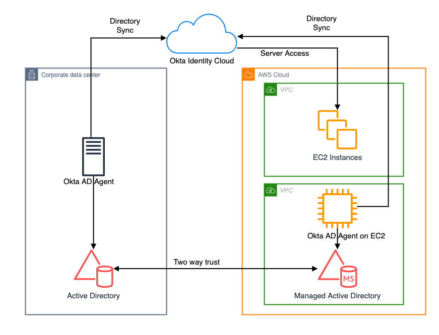
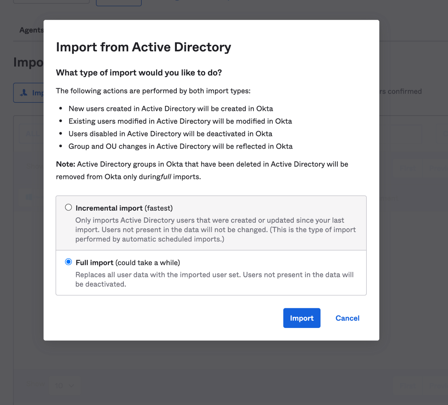
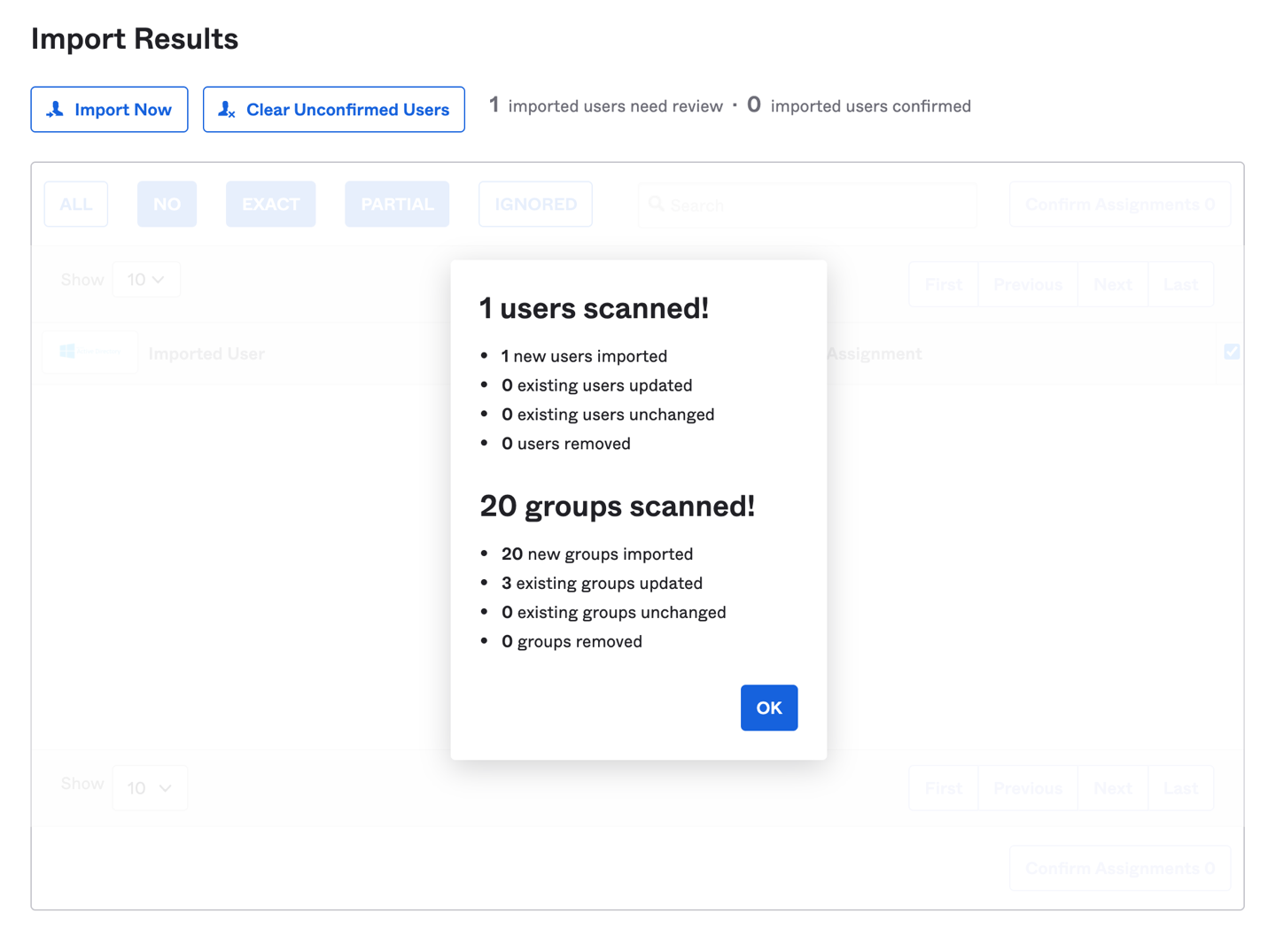
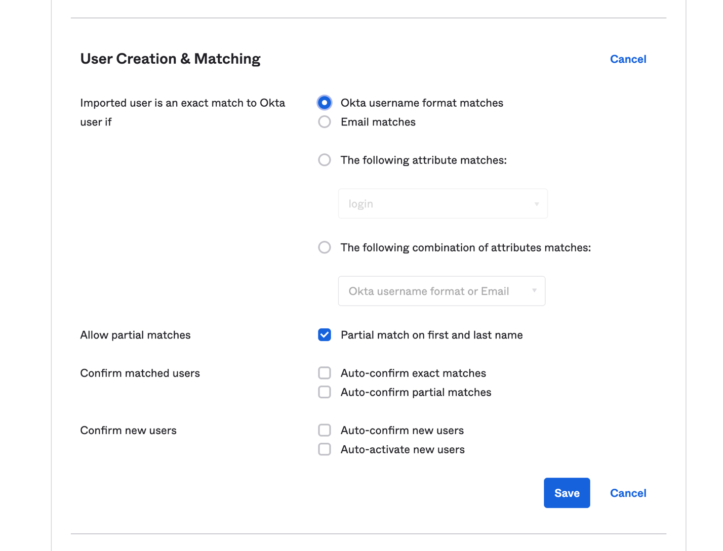
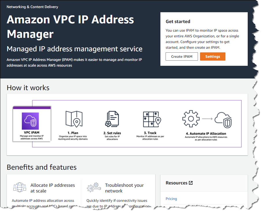


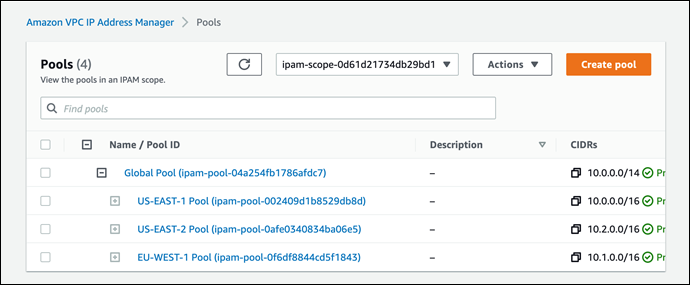

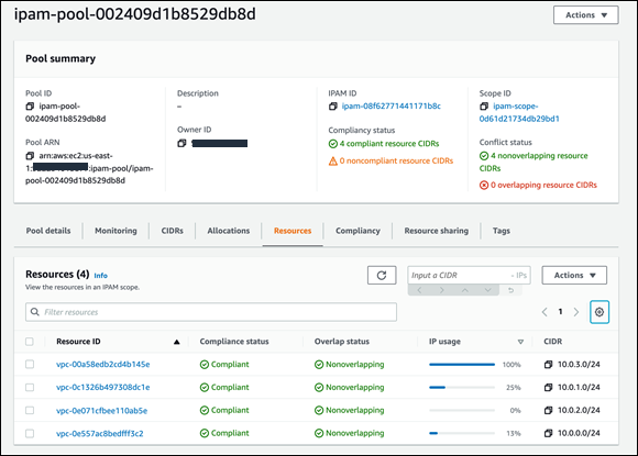
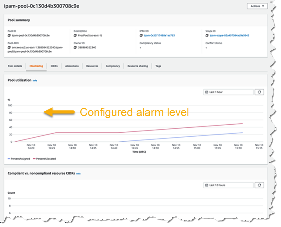
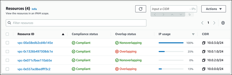

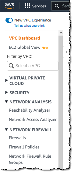
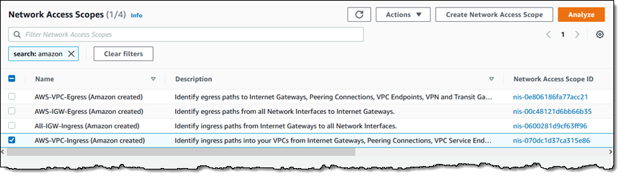


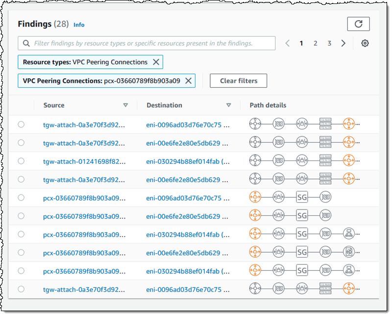
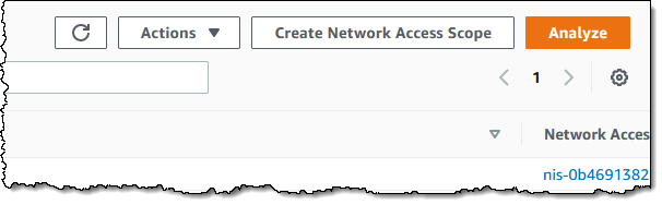

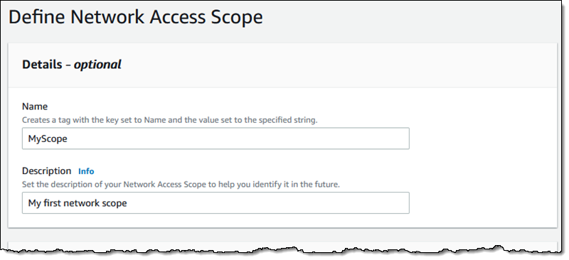
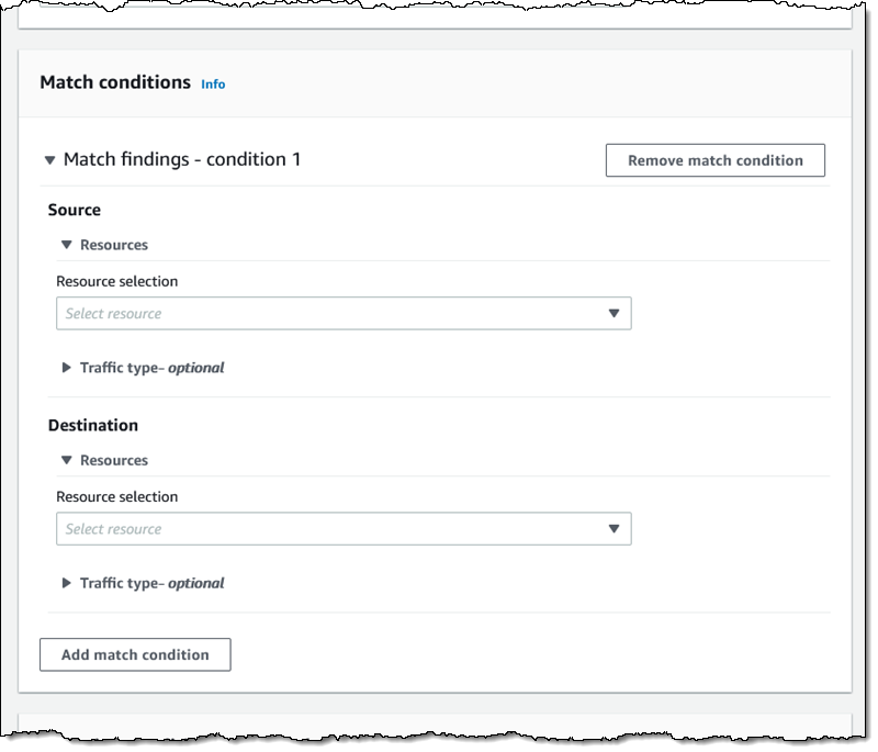
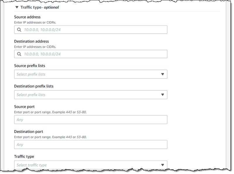


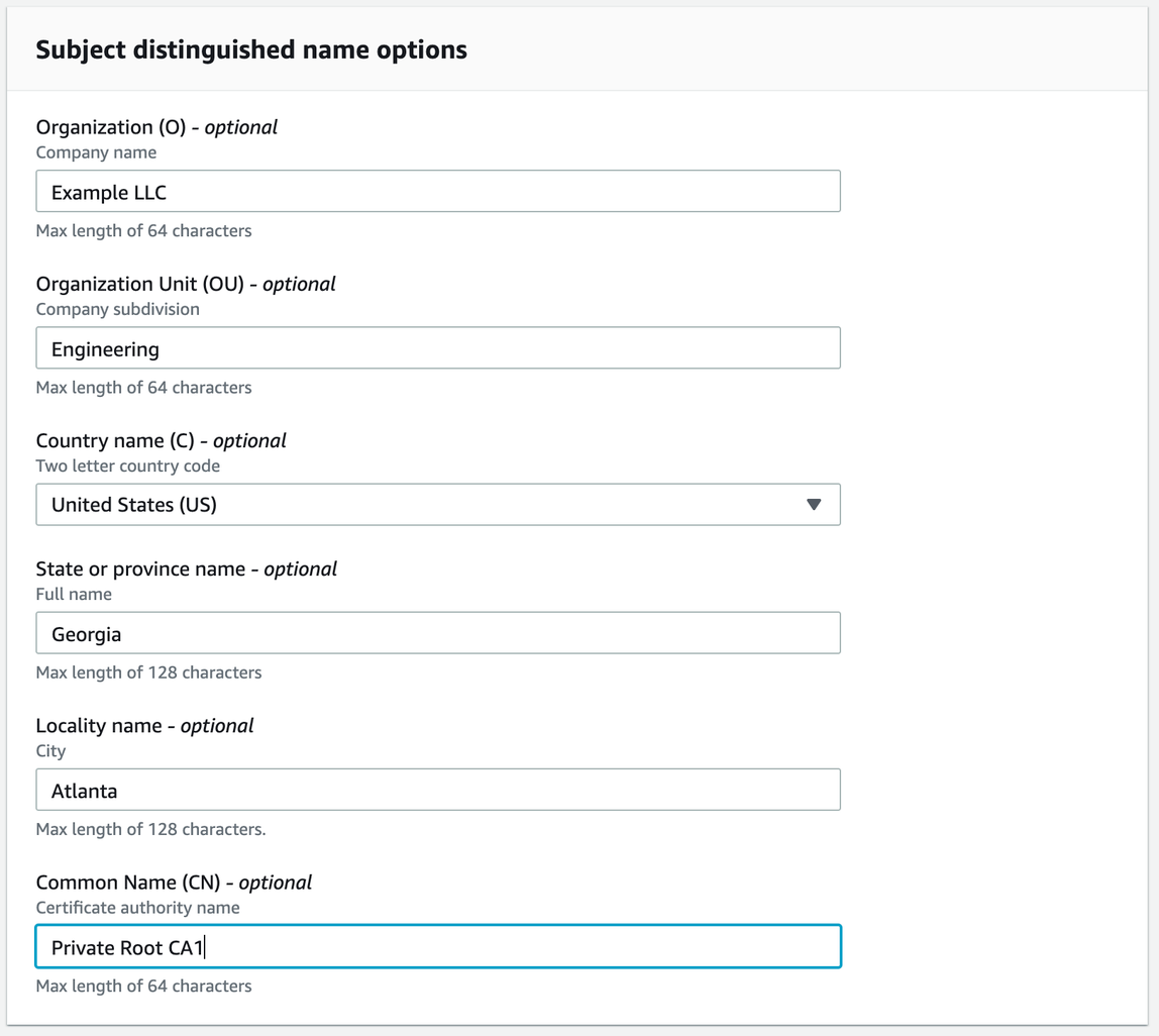
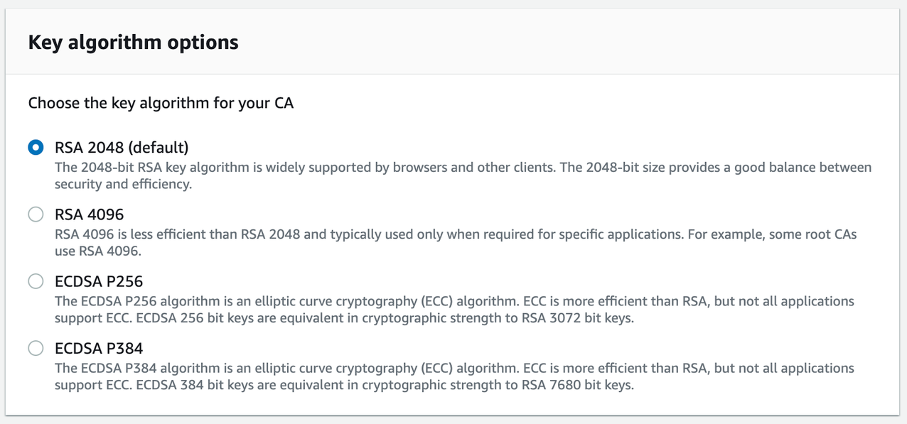


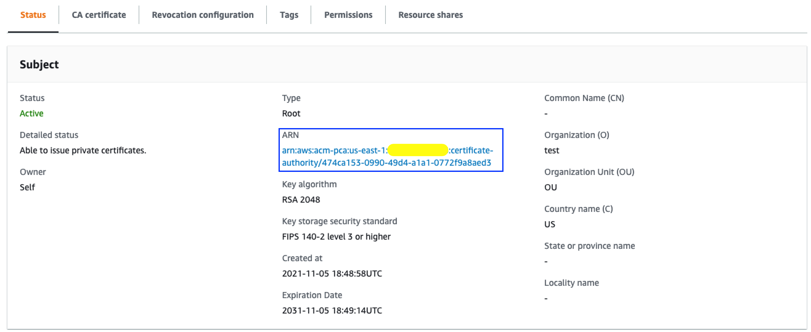
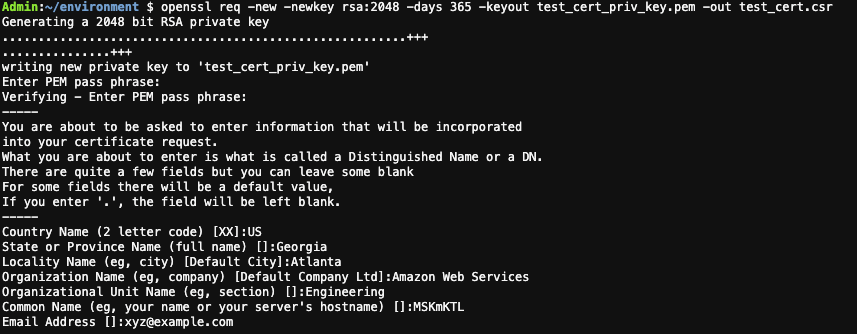


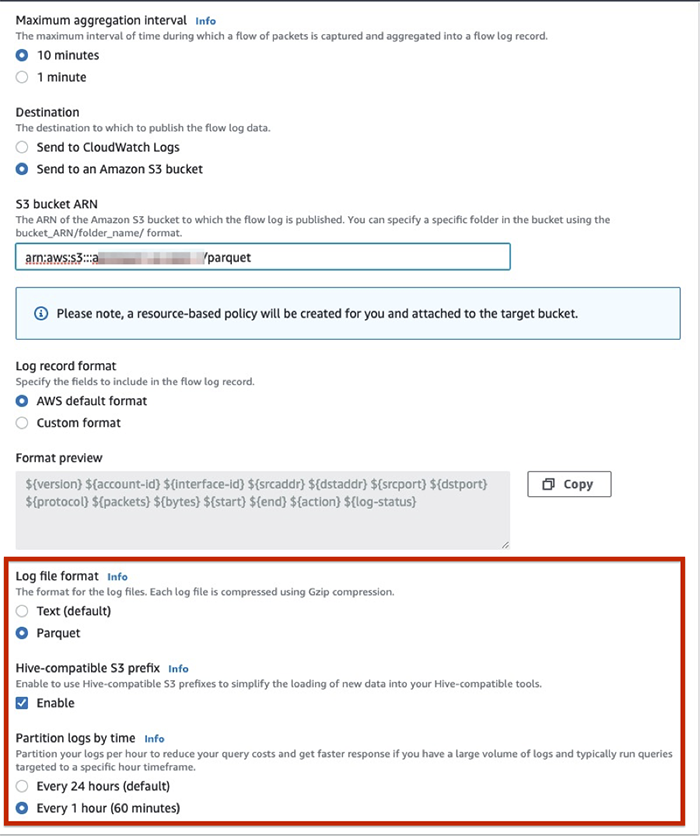
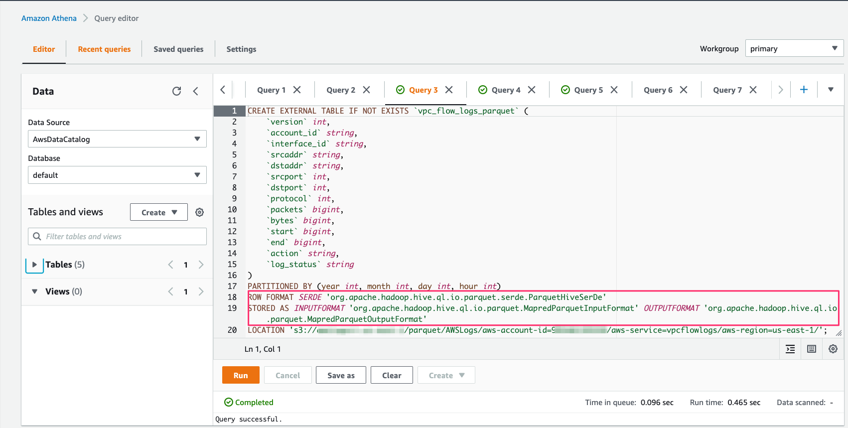
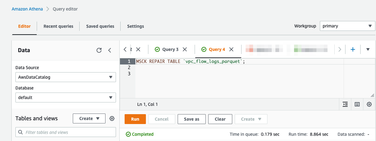
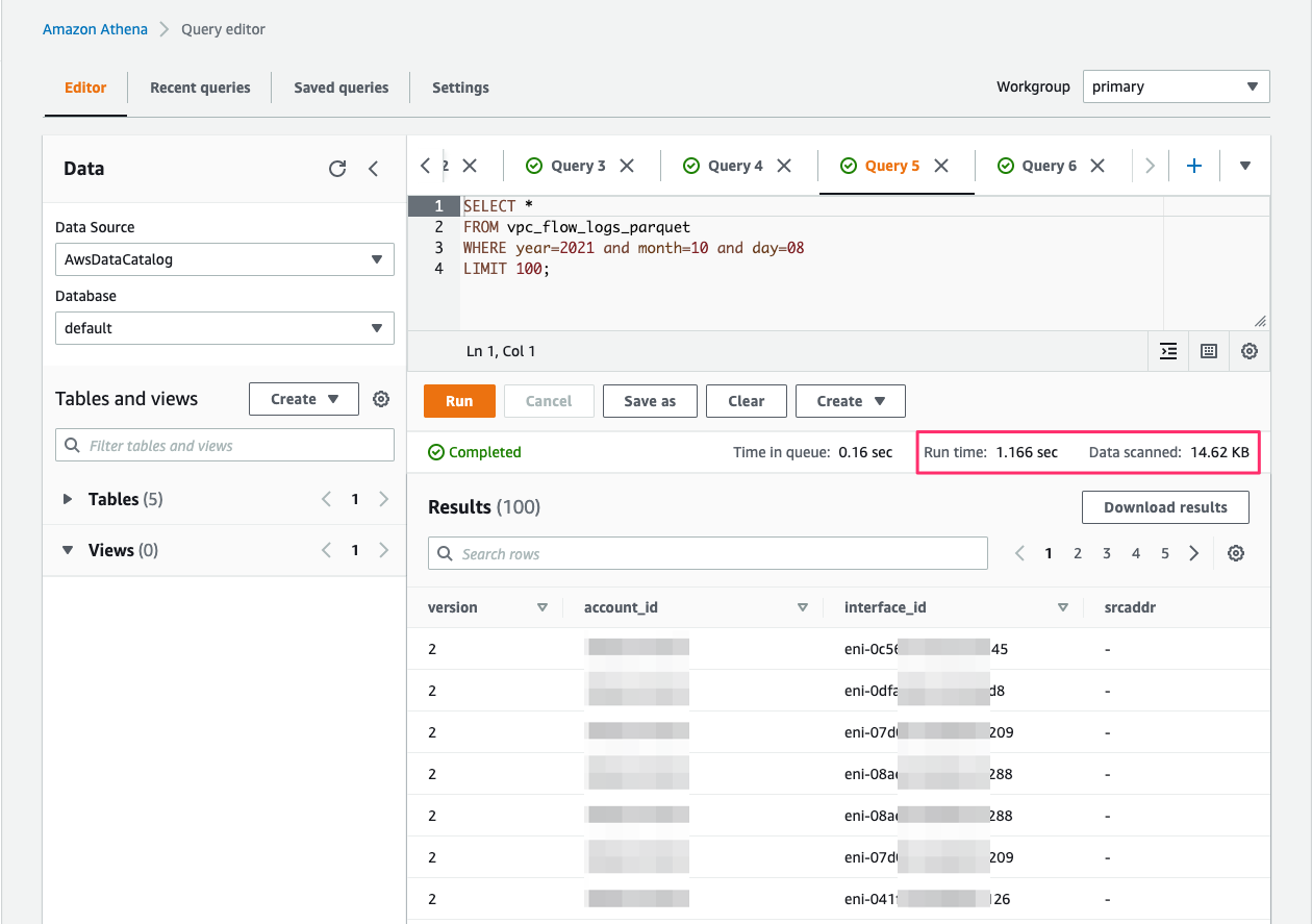

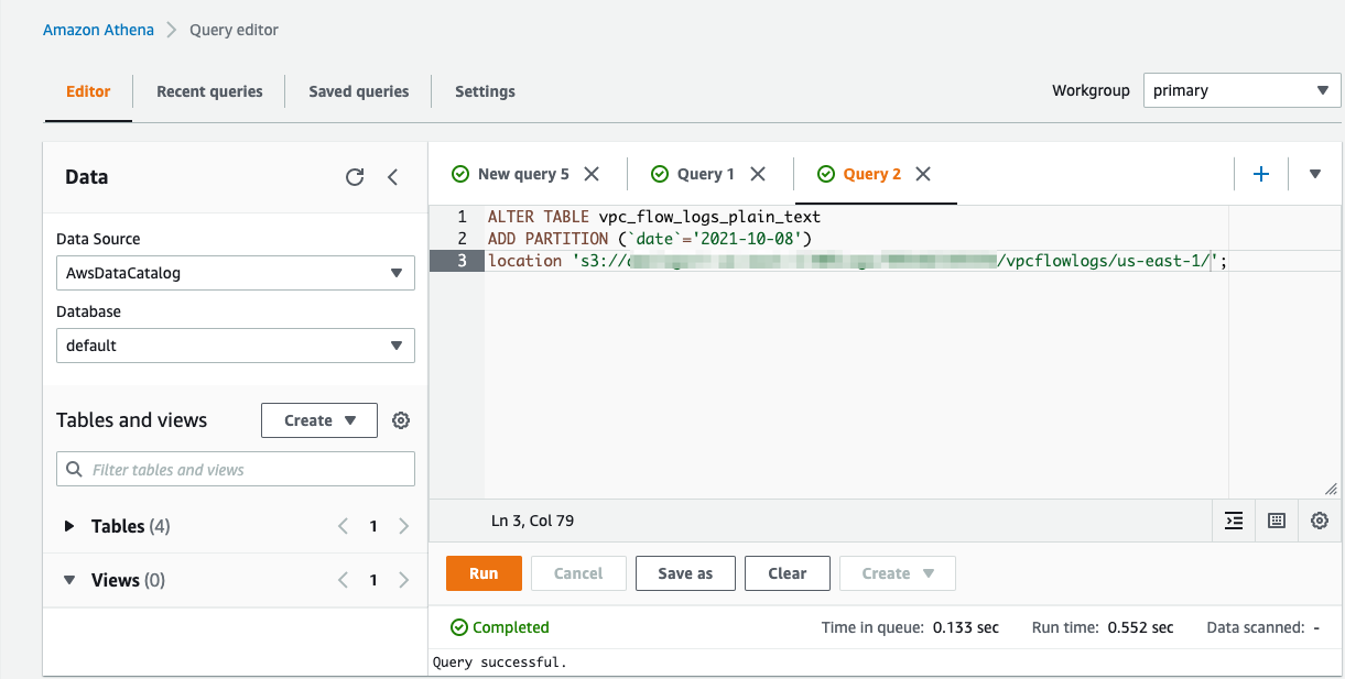
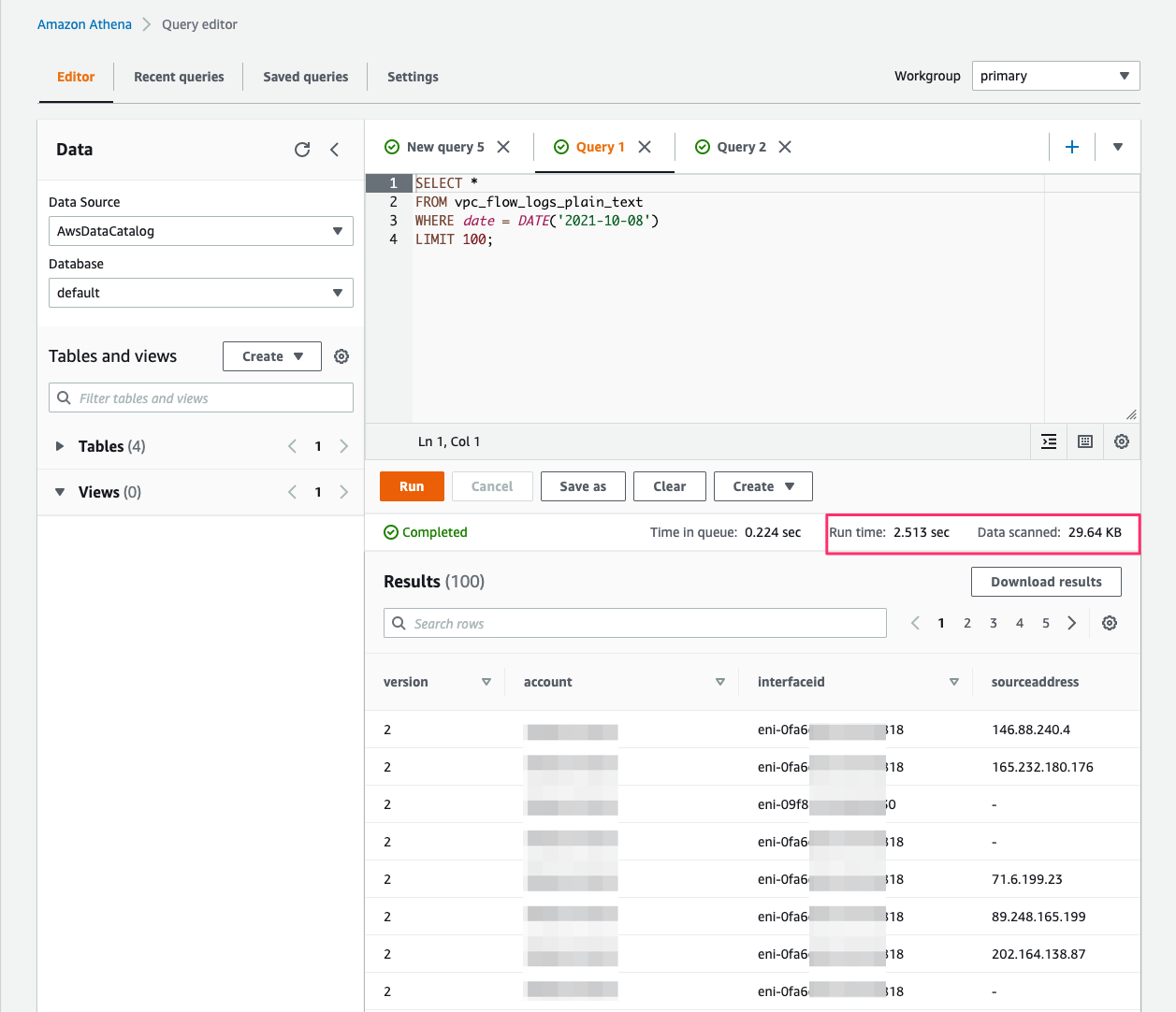


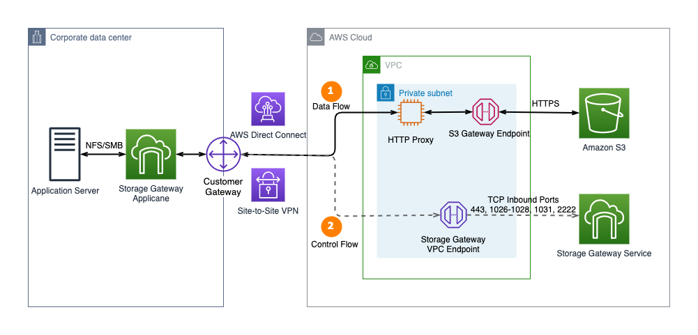
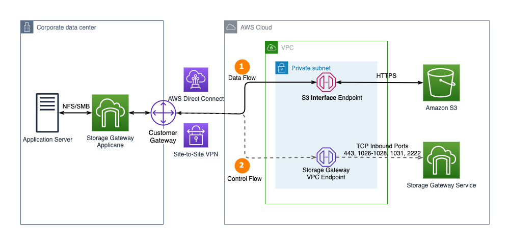
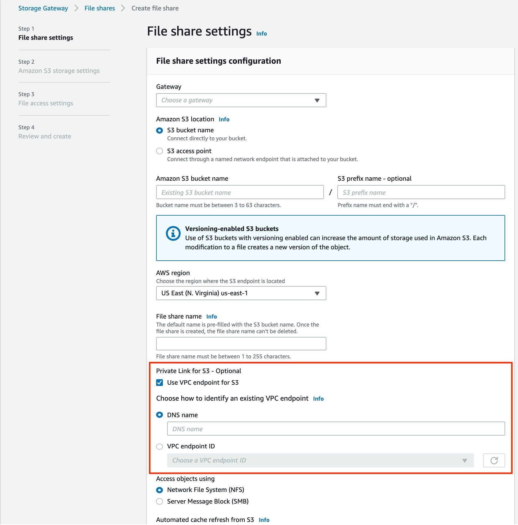
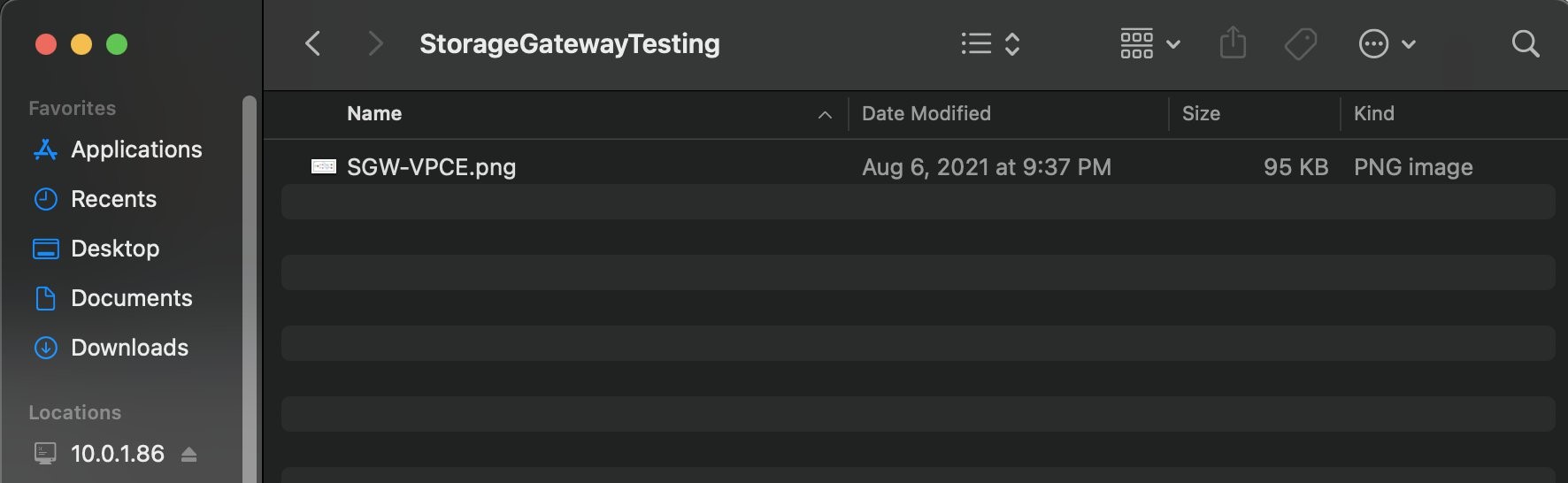
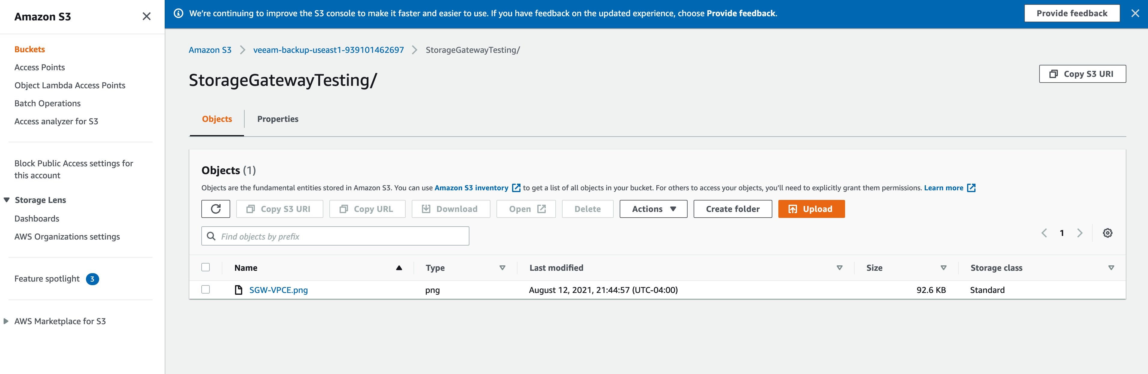
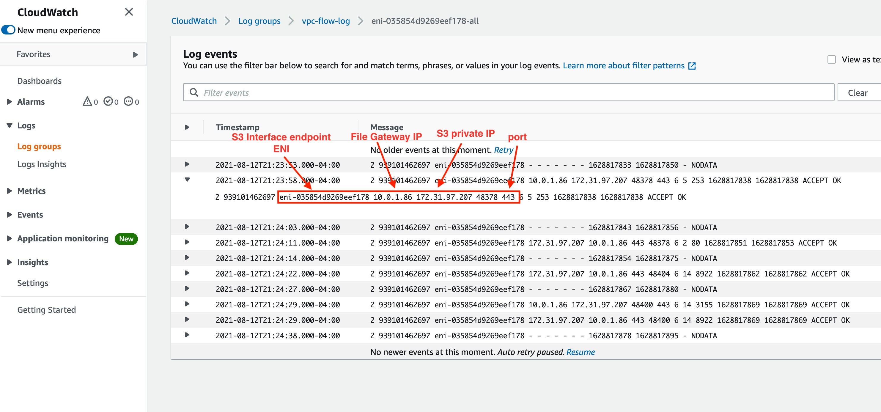


 Lotfi Mouhib is a Senior Solutions Architect working for the Public Sector team with Amazon Web Services. He helps public sector customers across EMEA realize their ideas, build new services, and innovate for citizens. In his spare time, Lotfi enjoys cycling and running.


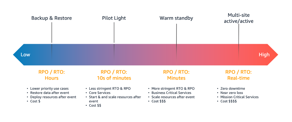


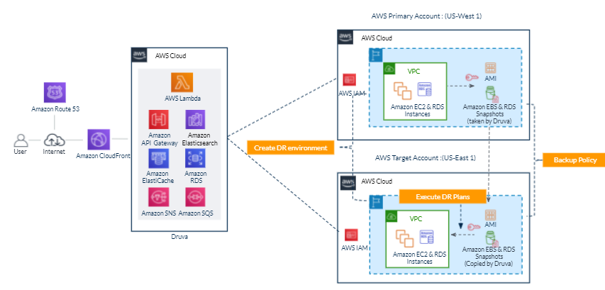
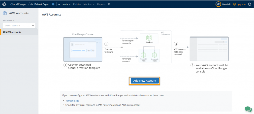
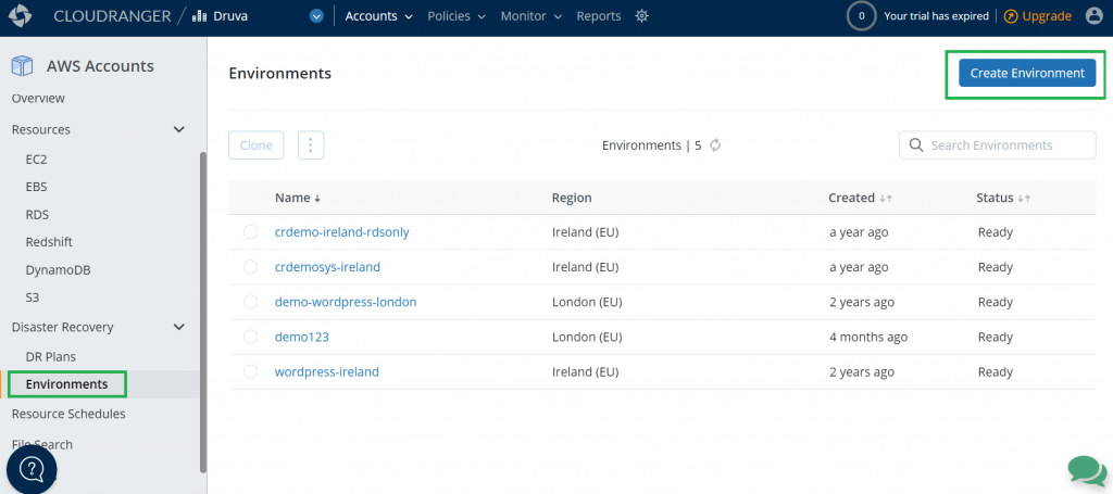
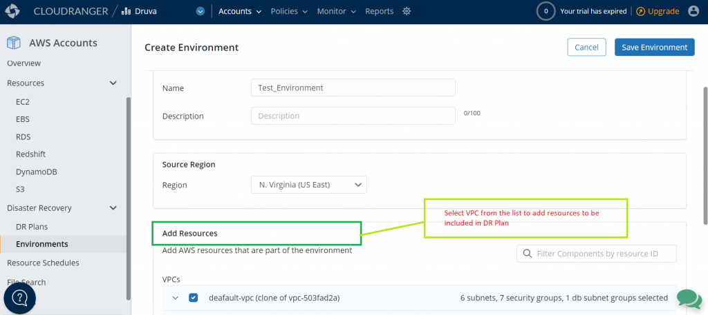
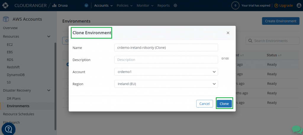
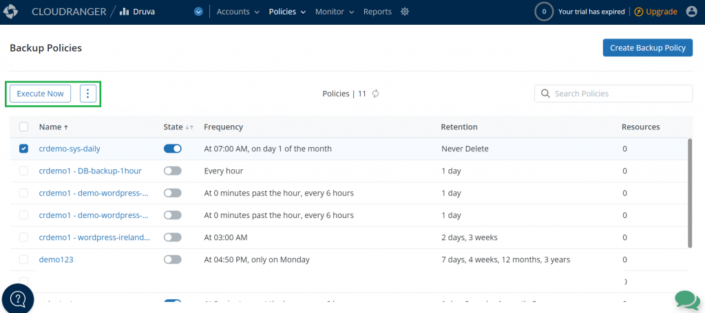
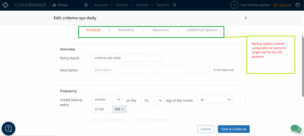
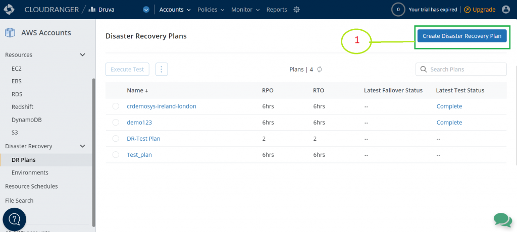
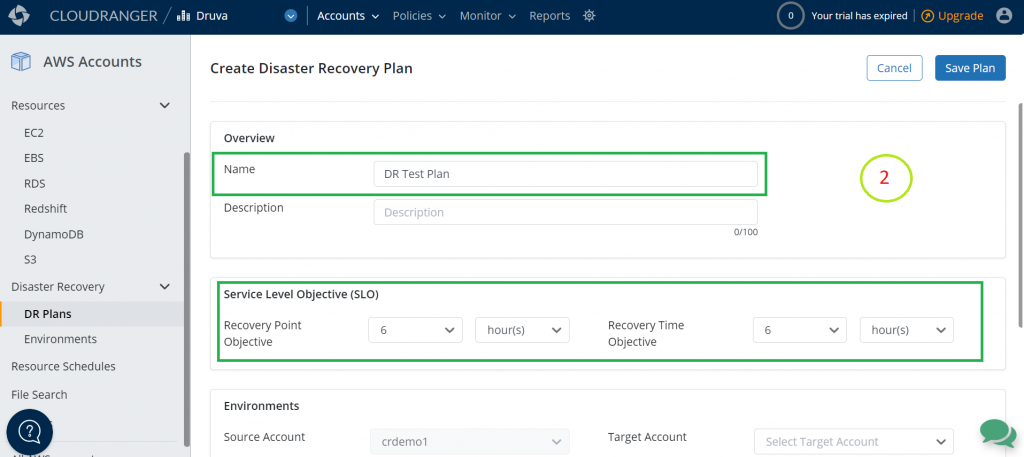
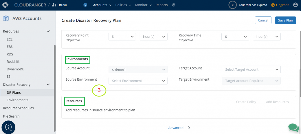
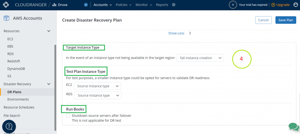
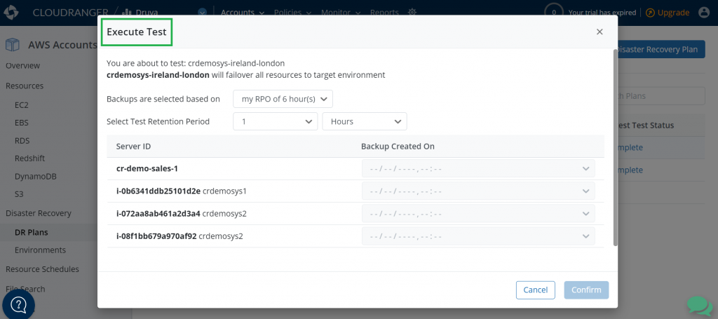

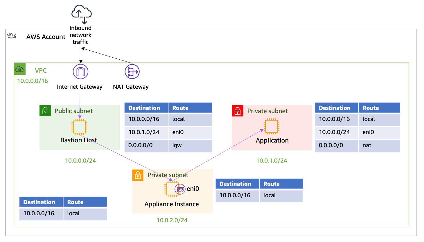

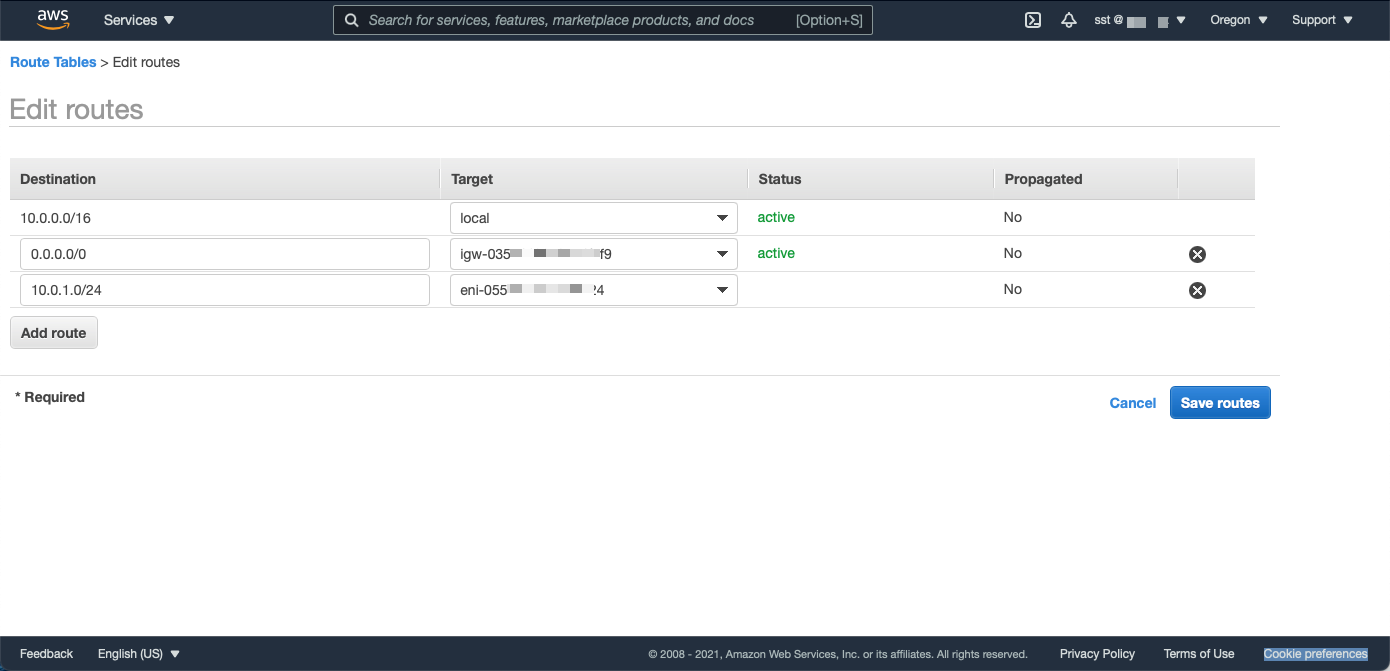


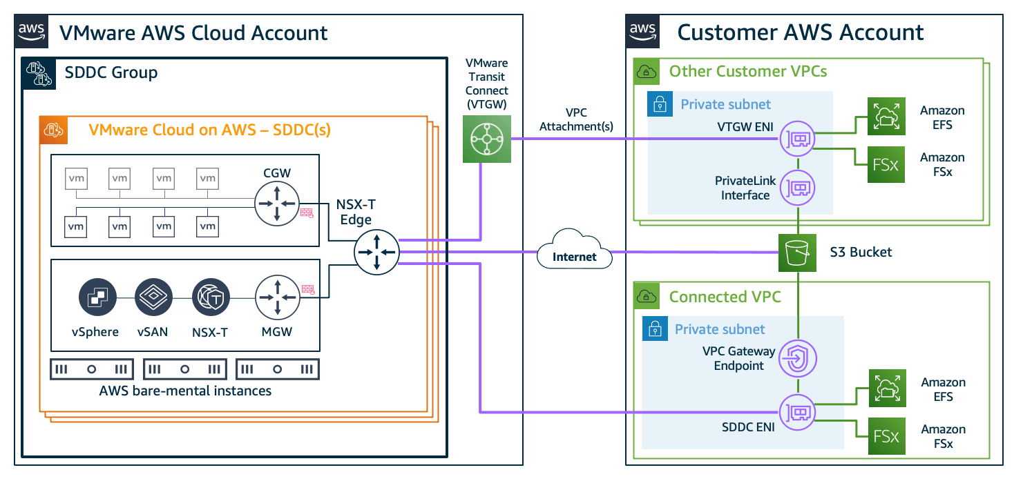


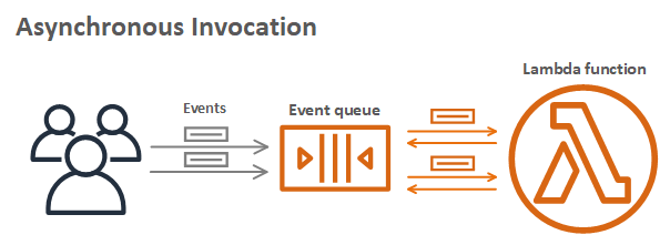


 Fifteen years ago today I wrote the blog post that launched the
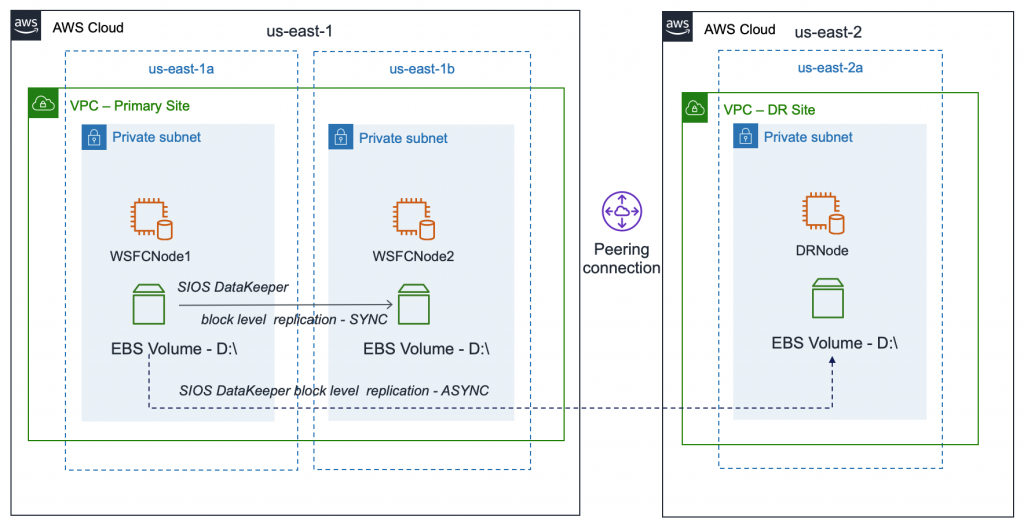
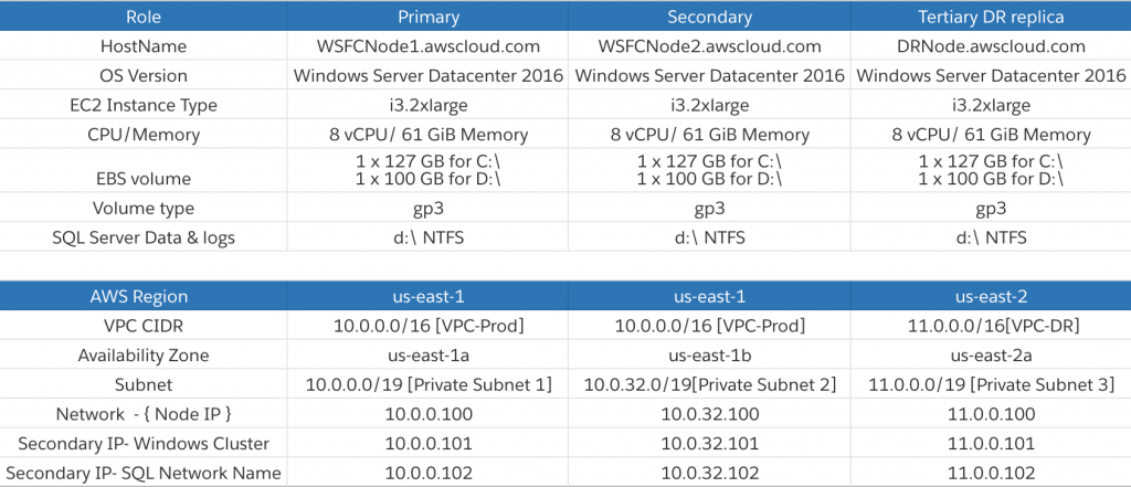
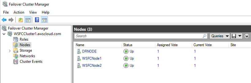


 For more information, see