Post Syndicated from Chaitanya Shah original https://aws.amazon.com/blogs/big-data/enrich-vpc-flow-logs-with-resource-tags-and-deliver-data-to-amazon-s3-using-amazon-kinesis-data-firehose/
VPC Flow Logs is an AWS feature that captures information about the network traffic flows going to and from network interfaces in Amazon Virtual Private Cloud (Amazon VPC). Visibility to the network traffic flows of your application can help you troubleshoot connectivity issues, architect your application and network for improved performance, and improve security of your application.
Each VPC flow log record contains the source and destination IP address fields for the traffic flows. The records also contain the Amazon Elastic Compute Cloud (Amazon EC2) instance ID that generated the traffic flow, which makes it easier to identify the EC2 instance and its associated VPC, subnet, and Availability Zone from where the traffic originated. However, when you have a large number of EC2 instances running in your environment, it may not be obvious where the traffic is coming from or going to simply based on the EC2 instance IDs or IP addresses contained in the VPC flow log records.
By enriching flow log records with additional metadata such as resource tags associated with the source and destination resources, you can more easily understand and analyze traffic patterns in your environment. For example, customers often tag their resources with resource names and project names. By enriching flow log records with resource tags, you can easily query and view flow log records based on an EC2 instance name, or identify all traffic for a certain project.
In addition, you can add resource context and metadata about the destination resource such as the destination EC2 instance ID and its associated VPC, subnet, and Availability Zone based on the destination IP in the flow logs. This way, you can easily query your flow logs to identify traffic crossing Availability Zones or VPCs.
In this post, you will learn how to enrich flow logs with tags associated with resources from VPC flow logs in a completely serverless model using Amazon Kinesis Data Firehose and the recently launched Amazon VPC IP Address Manager (IPAM), and also analyze and visualize the flow logs using Amazon Athena and Amazon QuickSight.
Solution overview
In this solution, you enable VPC flow logs and stream them to Kinesis Data Firehose. This solution enriches log records using an AWS Lambda function on Kinesis Data Firehose in a completely serverless manner. The Lambda function fetches resource tags for the instance ID. It also looks up the destination resource from the destination IP using the Amazon EC2 API and IPAM, and adds the associated VPC network context and metadata for the destination resource. It then stores the enriched log records in an Amazon Simple Storage Service (Amazon S3) bucket. After you have enriched your flow logs, you can query, view, and analyze them in a wide variety of services, such as AWS Glue, Athena, QuickSight, Amazon OpenSearch Service, as well as solutions from the AWS Partner Network such as Splunk and Datadog.
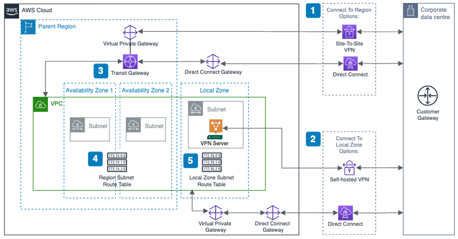
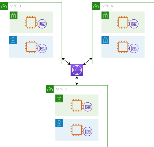
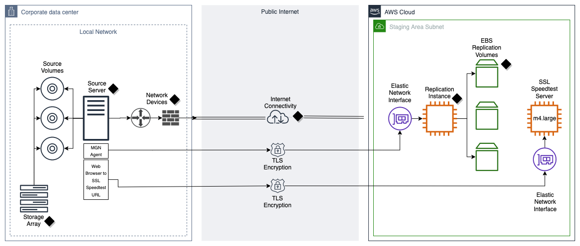
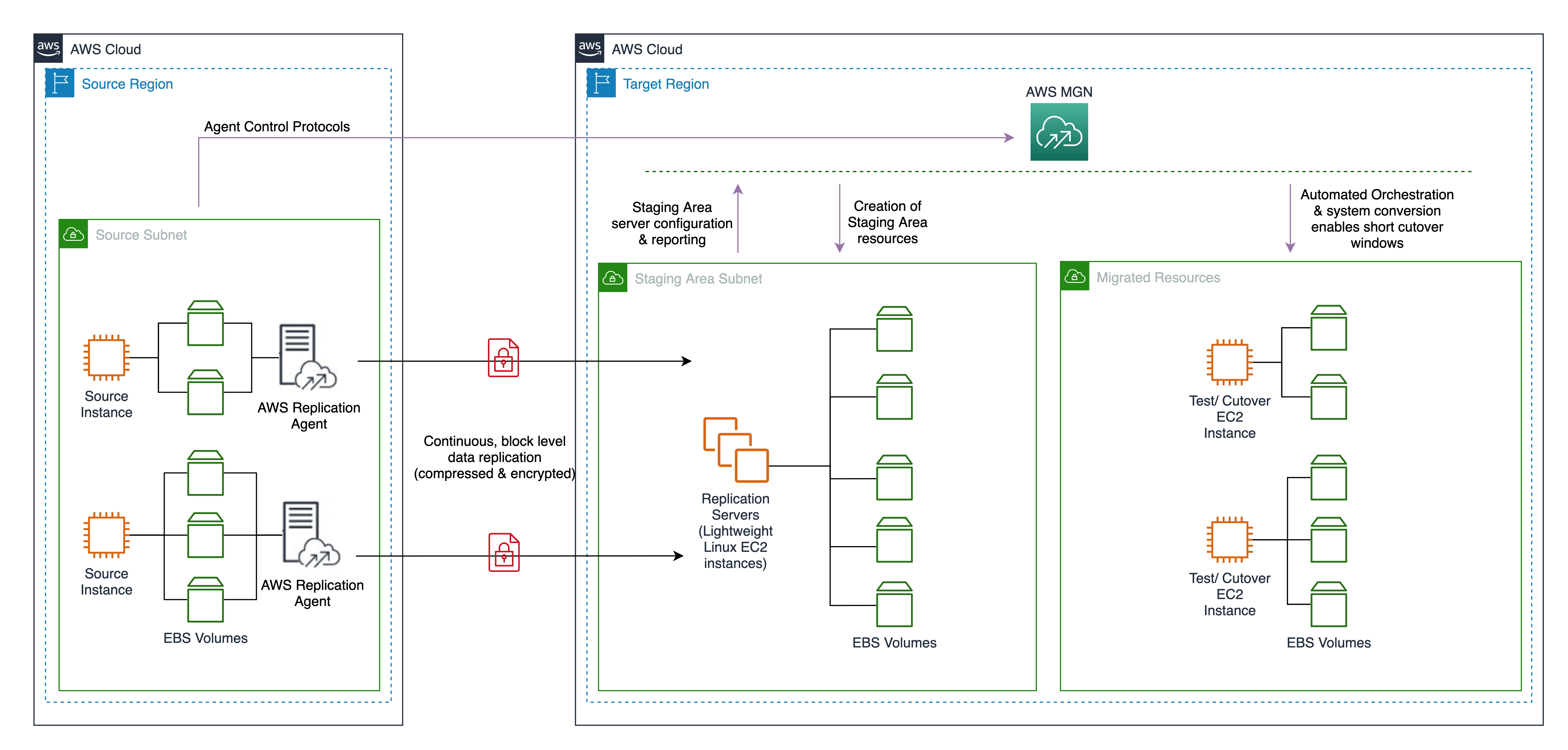
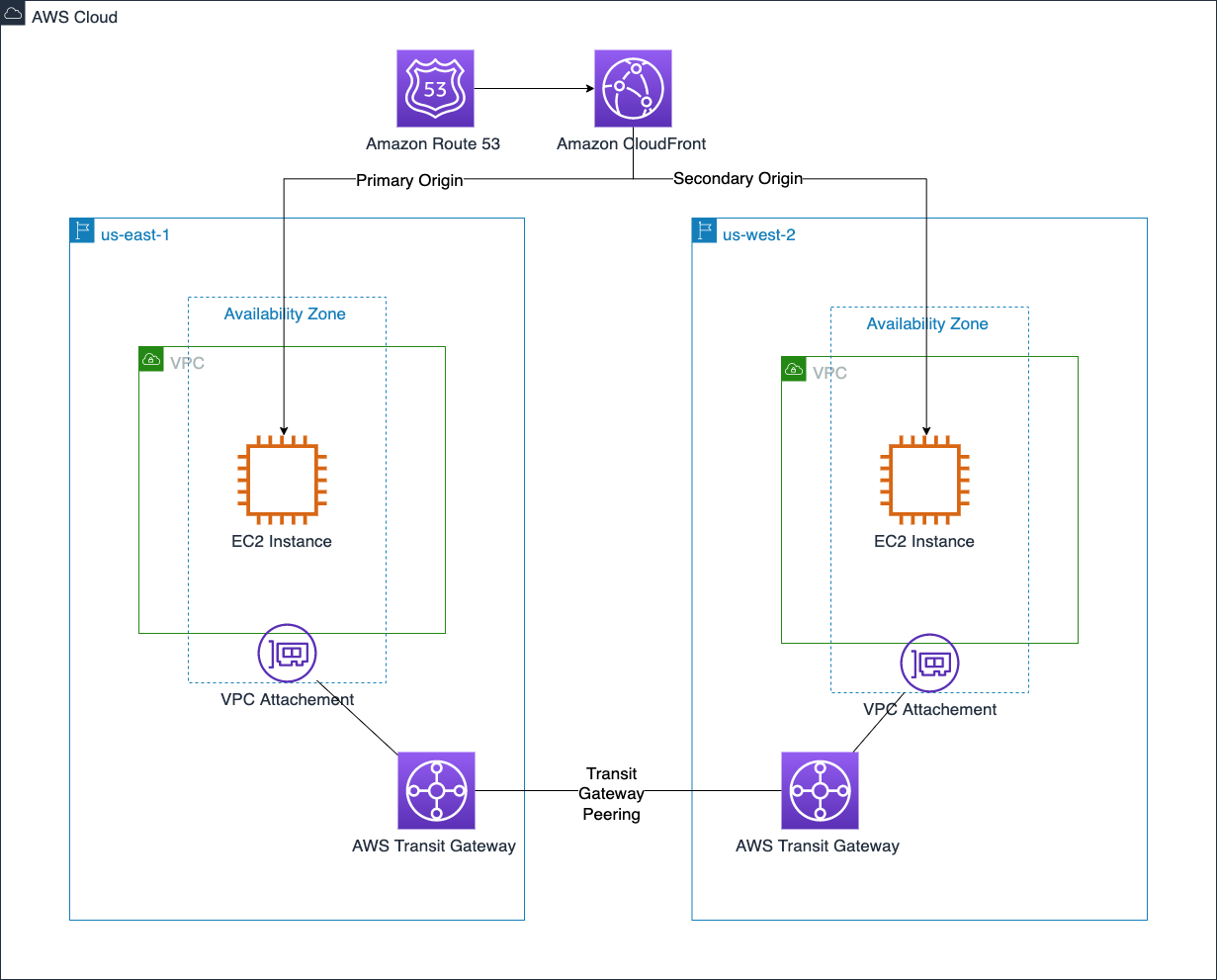
The following diagram illustrates the solution architecture.

The workflow contains the following steps:
- Amazon VPC sends the VPC flow logs to the Kinesis Data Firehose delivery stream.
- The delivery stream uses a Lambda function to fetch resource tags for instance IDs from the flow log record and add it to the record. You can also fetch tags for the source and destination IP address and enrich the flow log record.
- When the Lambda function finishes processing all the records from the Kinesis Data Firehose buffer with enriched information like resource tags, Kinesis Data Firehose stores the result file in the destination S3 bucket. Any failed records that Kinesis Data Firehose couldn’t process are stored in the destination S3 bucket under the prefix you specify during delivery stream setup.
- All the logs for the delivery stream and Lambda function are stored in Amazon CloudWatch log groups.
Prerequisites
As a prerequisite, you need to create the target S3 bucket before creating the Kinesis Data Firehose delivery stream.
If using a Windows computer, you need PowerShell; if using a Mac, you need Terminal to run AWS Command Line Interface (AWS CLI) commands. To install the latest version of the AWS CLI, refer to Installing or updating the latest version of the AWS CLI.
Create a Lambda function
You can download the Lambda function code from the GitHub repo used in this solution. The example in this post assumes you are enabling all the available fields in the VPC flow logs. You can use it as is or customize per your needs. For example, if you intend to use the default fields when enabling the VPC flow logs, you need to modify the Lambda function with the respective fields. Creating this function creates an AWS Identity and Access Management (IAM) Lambda execution role.
To create your Lambda function, complete the following steps:
- On the Lambda console, choose Functions in the navigation pane.
- Choose Create function.
- Select Author from scratch.
- For Function name, enter a name.
- For Runtime, choose Python 3.8.
- For Architecture, select x86_64.
- For Execution role, select Create a new role with basic Lambda permissions.
- Choose Create function.

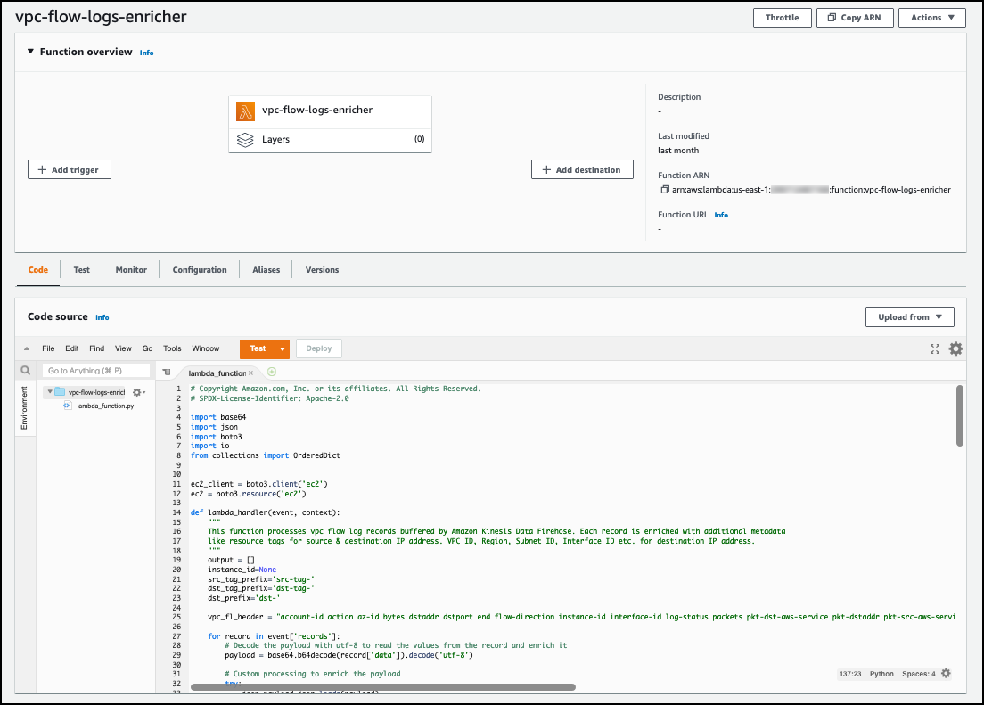
You can then see code source page, as shown in the following screenshot, with the default code in the lambda_function.py file.
- Delete the default code and enter the code from the GitHub Lambda function
aws-vpc-flowlogs-enricher.py. - Choose Deploy.
To enrich the flow logs with additional tag information, you need to create an additional IAM policy to give Lambda permission to describe tags on resources from the VPC flow logs.
- On the IAM console, choose Policies in the navigation pane.
- Choose Create policy.
- On the JSON tab, enter the JSON code as shown in the following screenshot.
This policy gives the Lambda function permission to retrieve tags for the source and destination IP and retrieve the VPC ID, subnet ID, and other relevant metadata for the destination IP from your VPC flow log record.
- Choose Next: Tags.

- Add any tags and choose Next: Review.
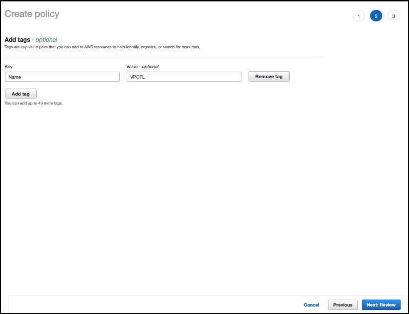
- For Name, enter
vpcfl-describe-tag-policy. - For Description, enter a description.
- Choose Create policy.

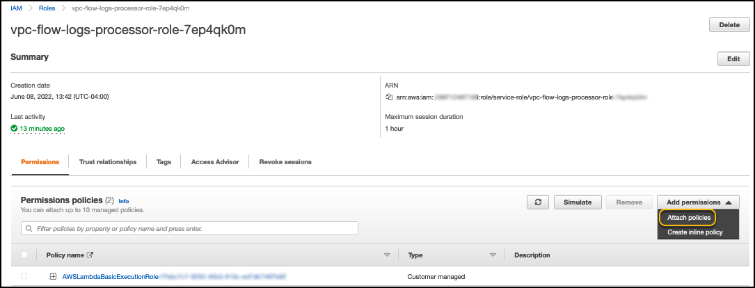
- Navigate to the previously created Lambda function and choose Permissions in the navigation pane.
- Choose the role that was created by Lambda function.
A page opens in a new tab.
- On the Add permissions menu, choose Attach policies.
- Search for the
vpcfl-describe-tag-policyyou just created. - Select the
vpcfl-describe-tag-policyand choose Attach policies.
Create the Kinesis Data Firehose delivery stream
To create your delivery stream, complete the following steps:
- On the Kinesis Data Firehose console, choose Create delivery stream.
- For Source, choose Direct PUT.
- For Destination, choose Amazon S3.
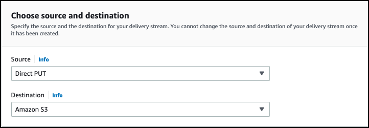
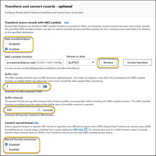
After you choose Amazon S3 for Destination, the Transform and convert records section appears.
- For Data transformation, select Enable.
- Browse and choose the Lambda function you created earlier.
- You can customize the buffer size as needed.
This impacts on how many records the delivery stream will buffer before it flushes it to Amazon S3.
- You can also customize the buffer interval as needed.
This impacts how long (in seconds) the delivery stream will buffer the incoming records from the VPC.
- Optionally, you can enable Record format conversion.
If you want to query from Athena, it’s recommended to convert it to Apache Parquet or ORC and compress the files with available compression algorithms, such as gzip and snappy. For more performance tips, refer to Top 10 Performance Tuning Tips for Amazon Athena. In this post, record format conversion is disabled.
- For S3 bucket, choose Browse and choose the S3 bucket you created as a prerequisite to store the flow logs.
- Optionally, you can specify the S3 bucket prefix. The following expression creates a Hive-style partition for year, month, and day:
AWSLogs/year=!{timestamp:YYYY}/month=!{timestamp:MM}/day=!{timestamp:dd}/
- Optionally, you can enable dynamic partitioning.
Dynamic partitioning enables you to create targeted datasets by partitioning streaming S3 data based on partitioning keys. The right partitioning can help you to save costs related to the amount of data that is scanned by analytics services like Athena. For more information, see Kinesis Data Firehose now supports dynamic partitioning to Amazon S3.
Note that you can enable dynamic partitioning only when you create a new delivery stream. You can’t enable dynamic partitioning for an existing delivery stream.

- Expand Buffer hints, compression and encryption.
- Set the buffer size to 128 and buffer interval to 900 for best performance.
- For Compression for data records, select GZIP.

Create a VPC flow log subscription
Now you create a VPC flow log subscription for the Kinesis Data Firehose delivery stream you created.
Navigate to AWS CloudShell or Terminal/PowerShell for a Mac or Windows computer and run the following AWS CLI command to enable the subscription. Provide your VPC ID for the parameter --resource-ids and delivery stream ARN for the parameter --log-destination.
If you’re running CloudShell for the first time, it will take a few seconds to prepare the environment to run.
After you successfully enable the subscription for your VPC flow logs, it takes a few minutes depending on the intervals mentioned in the setup to create the log record files in the destination S3 folder.
To view those files, navigate to the Amazon S3 console and choose the bucket storing the flow logs. You should see the compressed interval logs, as shown in the following screenshot.

You can download any file from the destination S3 bucket on your computer. Then extract the gzip file and view it in your favorite text editor.
The following is a sample enriched flow log record, with the new fields in bold providing added context and metadata of the source and destination IP addresses:
Create an Athena database and AWS Glue crawler
Now that you have enriched the VPC flow logs and stored them in Amazon S3, the next step is to create the Athena database and table to query the data. You first create an AWS Glue crawler to infer the schema from the log files in Amazon S3.
- On the AWS Glue console, choose Crawlers in the navigation pane.
- Choose Create crawler.

- For Name¸ enter a name for the crawler.
- For Description, enter an optional description.
- Choose Next.

- Choose Add a data source.
- For Data source¸ choose S3.
- For S3 path, provide the path of the flow logs bucket.
- Select Crawl all sub-folders.
- Choose Add an S3 data source.

- Choose Next.

- Choose Create new IAM role.
- Enter a role name.
- Choose Next.

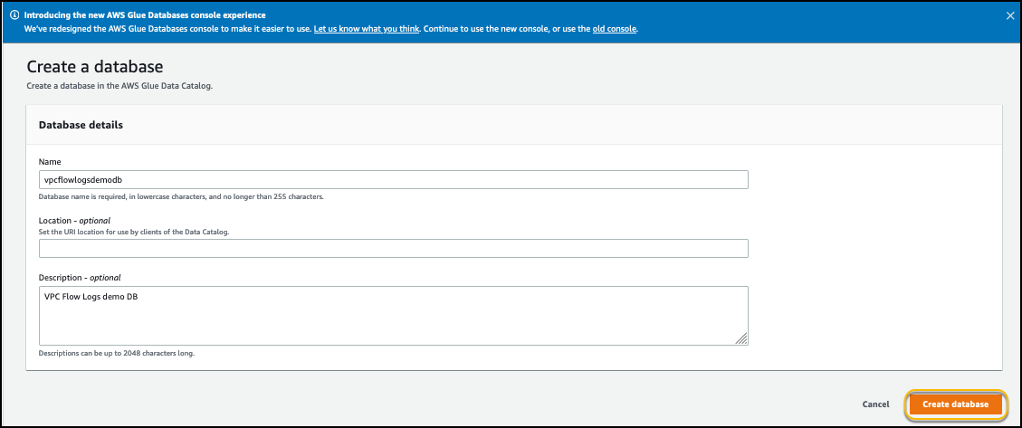
- Choose Add database.
- For Name, enter a database name.
- For Description, enter an optional description.
- Choose Create database.
- On the previous tab for the AWS Glue crawler setup, for Target database, choose the newly created database.
- Choose Next.
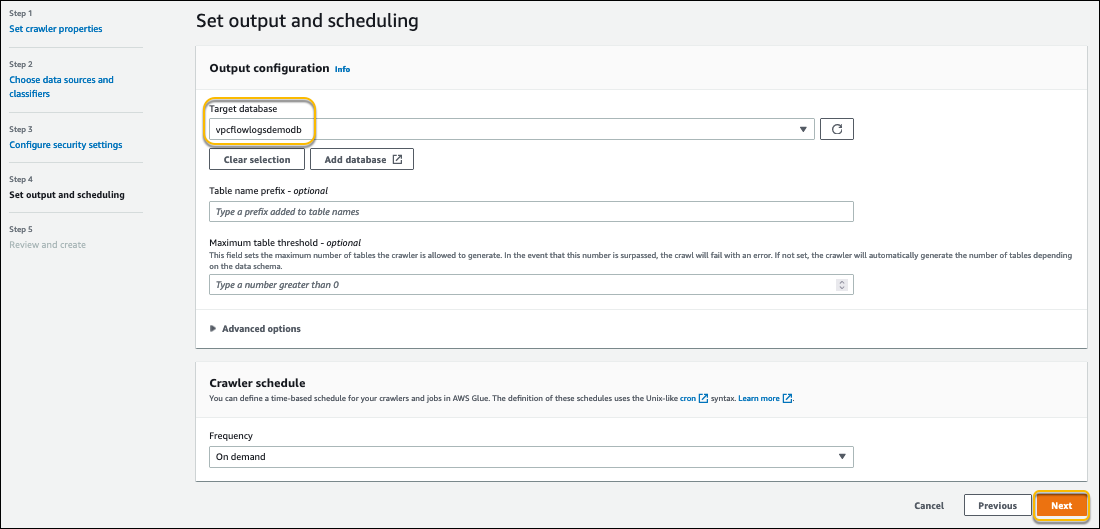
- Review the configuration and choose Create crawler.

- On the Crawlers page, select the crawler you created and choose Run.

You can rerun this crawler when new tags are added to your AWS resources, so that they’re available for you to query from the Athena database.
Run Athena queries
Now you’re ready to query the enriched VPC flow logs from Athena.
- On the Athena console, open the query editor.
- For Database, choose the database you created.
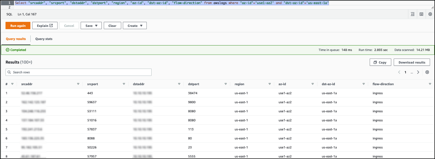
- Enter the query as shown in the following screenshot and choose Run.

The following code shows some of the sample queries you can run:
The following screenshot shows an example query result of the source Availability Zone to the destination Availability Zone traffic.
You can also visualize various charts for the flow logs stored in the S3 bucket via QuickSight. For more information, refer to Analyzing VPC Flow Logs using Amazon Athena, and Amazon QuickSight.
Pricing
For pricing details, refer to Amazon Kinesis Data Firehose pricing.
Clean up
To clean up your resources, complete the following steps:
- Delete the Kinesis Data Firehose delivery stream and associated IAM role and policies.
- Delete the target S3 bucket.
- Delete the VPC flow log subscription.
- Delete the Lambda function and associated IAM role and policy.
Conclusion
This post provided a complete serverless solution architecture for enriching VPC flow log records with additional information like resource tags using a Kinesis Data Firehose delivery stream and Lambda function to process logs to enrich with metadata and store in a target S3 file. This solution can help you query, analyze, and visualize VPC flow logs with relevant application metadata because resource tags have been assigned to resources that are available in the logs. This meaningful information associated with each log record wherever the tags are available makes it easy to associate log information to your application.
We encourage you to follow the steps provided in this post to create a delivery stream, integrate with your VPC flow logs, and create a Lambda function to enrich the flow log records with additional metadata to more easily understand and analyze traffic patterns in your environment.
About the Authors
 Chaitanya Shah is a Sr. Technical Account Manager with AWS, based out of New York. He has over 22 years of experience working with enterprise customers. He loves to code and actively contributes to AWS solutions labs to help customers solve complex problems. He provides guidance to AWS customers on best practices for their AWS Cloud migrations. He is also specialized in AWS data transfer and in the data and analytics domain.
 Vaibhav Katkade is a Senior Product Manager in the Amazon VPC team. He is interested in areas of network security and cloud networking operations. Outside of work, he enjoys cooking and the outdoors.