Tag Archives: Partner solutions

AWS Partner Central now available in AWS Management Console

Post Syndicated from Sébastien Stormacq original https://aws.amazon.com/blogs/aws/aws-partner-central-now-available-in-aws-management-console/

Today, we’re announcing that AWS Partner Central is now available directly in the AWS Management Console, creating a unified experience that transforms how you engage with AWS as both customers and AWS Partners.

As someone who has worked with countless AWS customers over the years, I’ve observed how organizations evolve in their AWS journey. Many of our most successful Partners began as AWS customers—first using our services to build their own infrastructure and solutions, then expanding to create offerings for others. Seeing this natural progression from customer to Partner, we recognized an opportunity to streamline these traditionally separate experiences into one unified journey.

As AWS evolved, so did the needs of our Partner community. Organizations today operate in multiple capacities: using AWS services for their own infrastructure while simultaneously building and delivering solutions for their customers. Modern businesses need streamlined workflows that support their growth from AWS customer to Partner to AWS Marketplace Seller, with enterprise-grade security features that match how they actually work with AWS today.

A new unified console experience
The integration of AWS Partner Central into the Console represents a fundamental shift in partnership accessibility. For existing AWS customers, such as you, becoming an AWS Partner is now as clear as accessing any other AWS service. The familiar console interface provides direct access to partnership opportunities, program benefits, and AWS Marketplace capabilities without needing separate logins or navigation between different systems.

Getting started as an AWS Partner now takes only a few clicks within your existing console environment. You can discover partnership opportunities, understand program requirements, and begin your Partner journey without leaving the AWS interface you already know and trust.

The console integration creates an intuitive pathway for existing customers to transition into AWS Marketplace Sellers. You can now access AWS Marketplace Seller capabilities alongside your existing AWS services, managing both your infrastructure and AWS Marketplace business from a single interface. Private offer requests and negotiations can be managed directly within AWS Partner Central, and you can manage your AWS Marketplace listings alongside your other AWS activities through streamlined workflows.

Becoming an AWS Partner
The unified console experience provides access to comprehensive partnership benefits designed to accelerate your business growth.

Join the AWS Partner Network (APN) and complete your Partner and AWS Marketplace Seller requirements seamlessly within the same interface. Enroll in Partner Paths that align with your customer solutions to build, market, list, and sell in AWS Marketplace while growing alongside AWS. When you are established, use the Partner programs to differentiate your solution, list in AWS Marketplace to improve your go-to-market discoverability, and build AWS expertise through certifications to drive profitability by capturing new revenue streams. Scale your business by selling or reselling software and professional services in AWS Marketplace, helping you accelerate deals, boost revenue, and expand your customer reach to new geographies, industries, and segments.

Throughout your journey, you can continue using Amazon Q in the console, which provides personalized guidance through AWS Partner Assistant.

Let’s see the new Partner Central console
The new AWS Partner Central is accessible like any other AWS service from the console. Among many new capabilities, it provides four key sections that support Partner operations and business growth within the AWS Partner Network:

1. It helps you sell your solutions

AWS Partner Central - Solutions

You can create and publish solutions that address specific customer needs through AWS Marketplace. Solutions are made up of products such as software as a service (SaaS), Amazon Machine Images (AMI), containers, professional services, AI agents and tools, and more. The solutions management capability guides you through building offerings that include both products you own and those you are authorized to resell. You can craft compelling value propositions and descriptions that clearly communicate your solution benefits to potential buyers browsing AWS Marketplace.

I choose Create solution to start listing a new solution in the AWS Marketplace, as shown in the following figure.

AWS Partner Central - Create solution

2. It helps you update and manage your Partner profile

AWS Partner Central - Manage profile

Your Partner profile showcases your organization’s expertise and capabilities to the AWS community. You control how your business appears to potential customers and Partners by highlighting the industry segments you serve and describing your primary products or services. Profile visibility settings provide you with the option to choose whether your information is public or private.

3. It helps you track opportunities

AWS Partner Central - Track Opportunities

You can manage your pipeline of AWS customers, supporting joint collaborations with AWS on customer engagements. You monitor these prospects using clear status indicators: approved, rejected, draft, and pending approval. The opportunity dashboard shows stages, estimated AWS Monthly Recurring Revenue, and other key metrics that help you understand your pipeline. You can create more opportunities directly within the console and export data for your own reporting and analysis.

4. It provides you with the ability to discover and connect with other Partners

After becoming an AWS Partner, you get access to the AWS Partners network, where you can search for other Partners. You can connect with them to collaborate on sales opportunities and expand your customer outreach.

AWS Partner Central - Discover and Search for partners

You search through available Partners using filters for industry, location, Partner program type, and specialization. The centralized dashboard shows your active connections, pending requests, and connection history, so that you can manage business relationships and identify collaboration opportunities that can expand your reach. Like all other AWS services, these Partner connection capabilities are now available as APIs, which provide automation and integration into your existing workflows.

AWS Partner Central - Manage contact requests

These capabilities work together within the new AWS Partner Central console, accessible directly from the console, helping you transition from AWS customer to successful Partner with enterprise-grade security and streamlined workflows.

The technical foundation: Migrating the identity system
This unified console experience is made possible by our migration to a modern identity system built on AWS Identity and Access Management (IAM). We’ve transitioned from legacy identity infrastructure to IAM Identity Center, providing enterprise-grade security capabilities including single sign-on capabilities and multi-factor authentication. With security as job zero, this migration provides new and existing Partners with the possibility to connect their own identity providers to AWS Partner Central. It provides seamless integration with existing enterprise authentication systems while removing the complexity of managing separate credentials across different services.

One more thing
APIs are the core of what we do at AWS, and AWS Partner Central is no different. You can automate and streamline your co-sell workflows by connecting your business tools to AWS Partner Central. The APIs offered by AWS Partner Central help you accelerate APN benefits—from Account Management (Account API) and Solution Management (Solution API) to co-selling with Opportunity and Leads APIs, and Benefits APIs for faster benefit activation.

You can use these APIs to engage with AWS and grow your Partner business from your own CRM tools.

Get started today
This integration between the console and AWS Partner Central reflects our commitment to reducing complexity and improving the Partner experience. We’re bringing AWS Partner Central into the console to create a more intuitive path for organizations to grow with AWS from initial customer adoption through to full partnership engagement and AWS Marketplace success.

Your journey from AWS customer to successful AWS Partner and AWS Marketplace Seller starts with a few clicks in your console. I encourage you to explore the new unified experience today and discover how AWS Partner Central in the console can accelerate your organization’s growth and success within the AWS community.

Ready to get started? Visit AWS Partner Central in your console to learn more about the AWS Partner Network and discover the partnership path that’s right for your organization.

— seb

Modernization of real-time payment orchestration on AWS

Post Syndicated from Neeraj Kaushik original https://aws.amazon.com/blogs/architecture/modernization-of-real-time-payment-orchestration-on-aws/

The global real-time payments market is experiencing significant growth. According to Fortune Business Insights, the market was valued at USD 24.91 billion in 2024 and is projected to grow to USD 284.49 billion by 2032, with a CAGR of 35.4%. Similarly, Grand View Research reports that the global mobile payment market, valued at USD 88.50 billion in 2024, is expected to grow at a CAGR of 38.0% from 2025 to 2030. (Disclaimer: Third-party market research and statistics are provided for informational purposed only. AWS and IBM make no representations about the accuracy of this information.)

This rapid expansion underscores the urgency for financial institutions to modernize their payment processing infrastructure. Financial institutions often need to process high volume of transactions with near-zero latency to meet stringent service level agreements (SLAs) to support surging mobile payments volume.

However, traditional payment orchestration systems, often built on monolithic architectures, struggle to meet these demands due to latency, availability, and scalability challenges. Additionally, their reliance on on-premises infrastructure leads to higher costs and an impediment to innovation, reinforcing the need for modernization.

As sustainability becomes a priority, organizations are turning to cloud-based solutions to optimize infrastructure, reduce carbon footprints, and enhance energy efficiency. This shift provides scalability and performance, and aligns with global sustainability goals, securing the future of real-time payments.

In this post, we discuss the real-time payment orchestration framework. It uses an event-driven architecture and AWS serverless services to enhance the resiliency, efficiency, and scalability of real-time payments. By decomposing payment processing into distinct business capabilities, financial institutions can improve modularity and flexibility. Implementing tenant-based segregation helps with data isolation and security. Additionally, adopting asynchronous communication through Amazon Managed Streaming for Apache Kafka (Amazon MSK) enhances scalability and resilience.

Traditional real-time payment orchestration

Payment orchestration serves as a middleware solution, streamlining transaction processing across multiple payment methods, gateways, and financial institutions. It orchestrates key business functions such as payment authorization, payment processing, settlement and clearing, compliance and risk management, and account management for both inbound and outbound payment flows.

The following diagram depicts the high-level business capabilities supported by payment orchestrators across various payment flows, including real-time payments, digital disbursements, tax payments, wires, and more.

Payment processing system flowchart showing main components from acceptance to billing

Detailed flowchart depicting a payment processing system with multiple components. The diagram shows primary payment types at the top (including Realtime Payments, Digital Disbursement, Credit Transfer, and Peer to Peer Payments) flowing down through core processing stages including Payment Acceptance, Execution, Clearing, Reporting, Tracking, Reversals, and Billing.

Many financial institutions adopt a tenant-based approach organized by geography due to varying clearing processes, localized regulations, and transaction requirements across AWS Regions. However, without proper separation of services, teams often continue to add region-specific logic to existing services, gradually increasing their monolithic complexity and using the same infrastructure for all payment flows.

Traditional payment systems process transactions linearly, with each step waiting for the previous one to complete. However, analysis of payment workflows reveals numerous opportunities for parallel execution:

  • Sanctions screening and fraud detection – Compliance and fraud checks can run simultaneously with initial routing decisions, rather than sequentially blocking all subsequent processing
  • Payment routing and authorization requests – When basic validations are complete, routing and authorization can proceed in parallel rather than one after another
  • Payment execution and ledger updates – The actual payment execution doesn’t need to wait for ledger records to be updated—these can occur concurrently
  • Settlement, reconciliation, and tracking – These post-transaction processes can be initiated independently as soon as the primary transaction is complete

This parallel approach can dramatically improve throughput and reduce latency compared to traditional queue-based systems where operations form a sequential chain that extends processing time and creates bottlenecks.

Most legacy payment orchestration systems rely heavily on on-premises virtual machines (VMs), leading to several challenges:

  • Multi-Region support for disaster recovery and multi-tenancy resulting in significant capital expenditure and operational overhead
  • High latency and SLA issues caused by sequential message processing and delays between globally separated data centers
  • Limited reusability of payment flows as monolithic architectures require region-specific changes for local clearing mechanisms and regulations, increasing complexity and costs
  • Scalability challenges and high memory consumption due to inefficient resource utilization and execution of irrelevant logic across regions
  • Complex cross-border payment routing caused by variations in clearing rules, transaction limits, and local regulations, increasing latency and routing errors
  • Integration challenges with diverse data formats because legacy systems rely on proprietary standards (for example, ISO 20022, SWIFT MT), complicating data conversion and compliance
  • High deployment complexity for new payment flows due to monolithic architectures requiring extensive region-specific modifications, slowing time to market
  • Environmental impact and high carbon footprint from on-premises infrastructure consuming excessive energy, whereas cloud-based approaches improve efficiency

Solution overview

To overcome these challenges, the proposed architecture embraces the following design principles to build a future-ready, real-time payment orchestration solution:

  • Performance at scale – Handling over 1,000 transactions per second (TPS) with consistent low latency under varying load conditions.
  • High availability – Achieving 99.999% uptime to meet the strict requirements of financial transactions.
  • Geographic resilience – Supporting global operations with region-specific compliance while maintaining consistent performance.
  • Cost optimization – Reducing total cost of ownership through efficient resource utilization and serverless technologies.
  • Security and compliance – Supporting data protection and regulatory adherence across different jurisdictions.
  • Operational simplicity – Streamlining deployment, monitoring, and maintenance across the payment ecosystem.
  • Microservices – Decomposing payment processing into distinct business capabilities, so financial institutions can improve modularity and flexibility. This microservices-based approach allows for independent scaling and development of critical components.

The following diagram depicts the high-level solution architecture for real-time payments. The existing channels using synchronous or asynchronous APIs can be modified to use edge-optimized endpoints to reduce latency.

Event-driven payment orchestration system with pub/sub channels connecting multiple payment processing modules

Architecture diagram detailing an AWS-based payment orchestration platform utilizing event-driven principles. Features reusable components across two regions, with dedicated modules for payment initiation, execution, reconciliation, billing, and risk management. Implements pub/sub messaging patterns for inter-component communication and connects to enterprise systems including accounting, compliance, and analytics.

An event-driven architecture is used for payment orchestration, which handles communication through a pub/sub pattern. This architecture maintains persistent connections, improving performance of the end-to-end real-time payment processing.

The event-driven architecture for real-time payment processing allows multiple payment operations to occur simultaneously using different adaptors, as opposed to the traditional systems where payment processes are sequential and flow through a single pipeline. Payment events are distributed to specialized payment processor microservices based on their function (initiation, execution, tracking, settlements), enabling each to process independently without waiting for others to complete.

Because we’re transitioning from sequential processing to distributed, maintaining transaction traceability is crucial. The payment tracking adapters shown in the preceding diagram connect to enterprise analytics systems, creating a specialized layer for monitoring transactions. The pub/sub model allows for attaching correlation IDs to events, enabling systems to track related events across different topics and processing stages.

A standardized event schema serves as the foundation for this architecture, providing consistency across regional deployments while allowing for customization at the adapter level. This schema defines uniform event structures containing tenant-specific metadata and supports versioning to accommodate evolving requirements. By isolating region-specific variations to the adapter layer, the solution maintains core functionality while interfacing with diverse enterprise systems through configuration-driven customization rather than code changes.

For most payment processes, especially those with independent processing steps that can run in parallel, this architecture delivers net performance gains despite the topic switching overhead, particularly for complex transactions where multiple independent validations or processing steps are required.

Deployment on the AWS Cloud

The solution uses edge-optimized Amazon API Gateway for channels. An edge-optimized API endpoint routes requests to the nearest Amazon CloudFront Point of Presence (POP), which can help in cases where your clients are geographically distributed to enable efficient routing within each geographical region, enhancing global responsiveness by minimizing network round trips and making sure requests take the shortest possible path before transitioning from the public internet to the client network.

The following diagram illustrates the high-level solution architecture for real-time payments.

Multi-region AWS payment architecture with managed Kafka topics connecting Lambda microservices and DynamoDB storage

Comprehensive AWS payment orchestration solution implementing modern cloud-native architecture principles. Core processing logic implemented as Lambda functions covering initiation, execution, reconciliation, billing, tracking, risk management, and settlement workflows. Leverages Amazon MSK for reliable event streaming between components, with dedicated Kafka topics for each processing stage. Data persistence handled by Amazon DynamoDB, supporting cross-region operations. Architecture demonstrates AWS best practices for financial services, including regional redundancy, serverless computing, managed services, and event-driven design patterns. System integrates with external banking infrastructure and enterprise systems while maintaining separation of concerns through microservices architecture. Features built-in support for compliance monitoring, risk management, and payment tracking through specialized Lambda functions.

The solution uses Amazon MSK to implement an event-driven architecture that efficiently handles both inbound and outbound channels traffic through API requests and asynchronous message-based events. Amazon MSK communicates using a high-performance binary protocol between producers, consumers, and brokers, providing low latency and high throughput. Real-time payments are logically partitioned across multiple tenants within geographical regions—North America, EMEA, LATAM, and Asia-Pacific.

Each real-time payment tenant follows an active/active disaster recovery strategy by deploying MSK clusters across multiple AWS Regions, designed to achieve high availability and resilience. Amazon MSK offer both serverless and provisioned cluster options. The team can decide to select one or the other depending on the non-functional requirements and team expertise. Amazon MSK automatically manages partition leadership with leaders in primary Regions and followers in secondary Regions. During failover, leaders are re-elected in healthy Regions, designed to help maintain processing capabilities during regional incidents. Sticky partitioning uses consistent hashing for deterministic routing, and cooperative rebalancing enables efficient failover. Multi-AZ deployment provides zone redundancy and isolated clusters per Region for data sovereignty compliance through programmatic AWS Identity and Access Management (IAM) and virtual private cloud (VPC) boundaries.

To support seamless cross-Region replication and maintain message continuity, Amazon MSK Replicator—a fully managed feature of Amazon MSK—is used to replicate topics and synchronize consumer group offsets across clusters. MSK Replicator simplifies the process of building multi-Region Kafka applications by not needing custom code, open-source tool configuration, or infrastructure management. It automatically provisions and scales the necessary resources, so teams can focus on business logic while only paying for the data being replicated. In the event of a regional outage or failover, traffic can be automatically redirected to a healthy Region without data loss or service disruption, providing near-zero Recovery Time Objectives (RTOs) and uninterrupted operations for downstream services such as payment processors and audit trail consumers.

In addition to regional redundancy, the architecture uses an event-driven architecture to enable parallel and decoupled processing of payment transactions. Events such as transaction initiation, validation, and settlement are emitted asynchronously and consumed by various microservices independently, which drastically reduces end-to-end latency.

To process these events at scale, the architecture can use AWS Lambda, Amazon Elastic Container Service (Amazon ECS), or Amazon Elastic Kubernetes Service (Amazon EKS) depending upon non-functional requirements. Automatic scaling responds to Amazon CloudWatch metrics, and exponential backoff retry logic with dead-letter queues (DLQs) handles throttling scenarios. Circuit breakers prevent cascade failures during high error rates.

One of the key benefits of the solution is the reusability of payment flows across different regions. Although each region has its own unique compliance requirements and settlement rules, the core functionalities of real-time payments (payment authorization, payment processing, settlement and clearing) are largely similar. This reusability enables rapid deployment of payment solutions across new regions without rearchitecting the entire system. For example, the real-time payment system in the US and UK might share similar business logic for real-time gross settlement but differ in the clearing and compliance requirements. The solution treats these as bounded contexts within the microservices architecture, providing flexibility while making sure each region can handle its own specific rules and regulations.

Sustainability

AWS relentlessly innovates its infrastructure design, build, and operations to make progress towards net-zero carbon by 2040 and being water positive by 2030. Amazon MSK with AWS Graviton based instances use up to 60% less energy than comparable M5 instances, helping you achieve your sustainability goals. Lambda is inherently sustainable by design. Its serverless model makes sure compute resources are only used when needed, drastically reducing idle infrastructure and wasted energy. Instead of keeping always-on servers for infrequent tasks, Lambda provisions compute power just-in-time, achieving near-zero idle capacity.

Security and compliance in financial services

Given the sensitive nature of payment transactions and financial data, you should apply the security controls required to meet financial regulations such as AWS PCI DSS and AWS Federal Information Processing Standard (FIPS) 140-3 according to your organization’s needs.

The solution should incorporate multi-layered security controls, continuous monitoring, and automated compliance auditing to meet the rigorous expectations of banking regulators and internal risk teams. For more information, refer to Security Guidance.

Conclusion

The modernization of payment orchestration systems using an event-driven architecture and AWS serverless technologies marks a significant advancement in meeting the demands of today’s rapidly evolving financial services landscape. This solution addresses the key challenges faced by traditional payment systems while delivering substantial benefits in performance, scalability, cost optimization, global resilience, sustainability, and compliance. By using cutting-edge cloud technologies and robust security controls, financial institutions can now build a future-ready foundation that adapts to evolving business needs while maintaining the highest standards of performance, security, and reliability. As the real-time payments market continues its explosive growth, this modern architecture provides a solution that meets today’s demands and is also well-positioned to support tomorrow’s payment innovations. Organizations looking to modernize their payment infrastructure can use this blueprint to accelerate their digital transformation journey, supporting sustainable, secure, and efficient payment processing at scale in an increasingly competitive global marketplace.

The architecture presented here is for reference purposes only. IBM will work closely with you to deploy the solution in accordance with industry standards and compliance requirements.For additional resources, refer to:

IBM Consulting is an AWS Premier Tier Services Partner that helps customers who use AWS to harness the power of innovation and drive their business transformation. They are recognized as a Global Systems Integrator (GSI) for over 22 competencies, including Financial Services Consulting. For additional information, please contact an IBM Representative.

Break down data silos and seamlessly query Iceberg tables in Amazon SageMaker from Snowflake

Post Syndicated from Nidhi Gupta original https://aws.amazon.com/blogs/big-data/break-down-data-silos-and-seamlessly-query-iceberg-tables-in-amazon-sagemaker-from-snowflake/

Organizations often struggle to unify their data ecosystems across multiple platforms and services. The connectivity between Amazon SageMaker and Snowflake’s AI Data Cloud offers a powerful solution to this challenge, so businesses can take advantage of the strengths of both environments while maintaining a cohesive data strategy.

In this post, we demonstrate how you can break down data silos and enhance your analytical capabilities by querying Apache Iceberg tables in the lakehouse architecture of SageMaker directly from Snowflake. With this capability, you can access and analyze data stored in Amazon Simple Storage Service (Amazon S3) through AWS Glue Data Catalog using an AWS Glue Iceberg REST endpoint, all secured by AWS Lake Formation, without the need for complex extract, transform, and load (ETL) processes or data duplication. You can also automate table discovery and refresh using Snowflake catalog-linked databases for Iceberg. In the following sections, we show how to set up this integration so Snowflake users can seamlessly query and analyze data stored in AWS, thereby improving data accessibility, reducing redundancy, and enabling more comprehensive analytics across your entire data ecosystem.

Business use cases and key benefits

The capability to query Iceberg tables in SageMaker from Snowflake delivers significant value across multiple industries:

  • Financial services – Enhance fraud detection through unified analysis of transaction data and customer behavior patterns
  • Healthcare – Improve patient outcomes through integrated access to clinical, claims, and research data
  • Retail – Increase customer retention rates by connecting sales, inventory, and customer behavior data for personalized experiences
  • Manufacturing – Boost production efficiency through unified sensor and operational data analytics
  • Telecommunications – Reduce customer churn with comprehensive analysis of network performance and customer usage data

Key benefits of this capability include:

  • Accelerated decision-making – Reduce time to insight through integrated data access across platforms
  • Cost optimization – Accelerate time to insight by querying data directly in storage without the need for ingestion
  • Improved data fidelity – Reduce data inconsistencies by establishing a single source of truth
  • Enhanced collaboration – Increase cross-functional productivity through simplified data sharing between data scientists and analysts

By using the lakehouse architecture of SageMaker with Snowflake’s serverless and zero-tuning computational power, you can break down data silos, enabling comprehensive analytics and democratizing data access. This integration supports a modern data architecture that prioritizes flexibility, security, and analytical performance, ultimately driving faster, more informed decision-making across the enterprise.

Solution overview

The following diagram shows the architecture for catalog integration between Snowflake and Iceberg tables in the lakehouse.

Catalog integration to query Iceberg tables in S3 bucket using Iceberg REST Catalog (IRC) with credential vending

The workflow consists of the following components:

  • Data storage and management:
    • Amazon S3 serves as the primary storage layer, hosting the Iceberg table data
    • The Data Catalog maintains the metadata for these tables
    • Lake Formation provides credential vending
  • Authentication flow:
    • Snowflake initiates queries using a catalog integration configuration
    • Lake Formation vends temporary credentials through AWS Security Token Service (AWS STS)
    • These credentials are automatically refreshed based on the configured refresh interval
  • Query flow:
    • Snowflake users submit queries against the mounted Iceberg tables
    • The AWS Glue Iceberg REST endpoint processes these requests
    • Query execution uses Snowflake’s compute resources while reading directly from Amazon S3
    • Results are returned to Snowflake users while maintaining all security controls

There are four patterns to query Iceberg tables in SageMaker from Snowflake:

  • Iceberg tables in an S3 bucket using an AWS Glue Iceberg REST endpoint and Snowflake Iceberg REST catalog integration, with credential vending from Lake Formation
  • Iceberg tables in an S3 bucket using an AWS Glue Iceberg REST endpoint and Snowflake Iceberg REST catalog integration, using Snowflake external volumes to Amazon S3 data storage
  • Iceberg tables in an S3 bucket using AWS Glue API catalog integration, also using Snowflake external volumes to Amazon S3
  • Amazon S3 Tables using Iceberg REST catalog integration with credential vending from Lake Formation

In this post, we implement the first of these four access patterns using catalog integration for the AWS Glue Iceberg REST endpoint with Signature Version 4 (SigV4) authentication in Snowflake.

Prerequisites

You must have the following prerequisites:

The solution takes approximately 30–45 minutes to set up. Cost varies based on data volume and query frequency. Use the AWS Pricing Calculator for specific estimates.

Create an IAM role for Snowflake

To create an IAM role for Snowflake, you first create a policy for the role:

  1. On the IAM console, choose Policies in the navigation pane.
  2. Choose Create policy.
  3. Choose the JSON editor and enter the following policy (provide your AWS Region and account ID), then choose Next.
{
     "Version": "2012-10-17",
     "Statement": [
         {
             "Sid": "AllowGlueCatalogTableAccess",
             "Effect": "Allow",
             "Action": [
                 "glue:GetCatalog",
                 "glue:GetCatalogs",
                 "glue:GetPartitions",
                 "glue:GetPartition",
                 "glue:GetDatabase",
                 "glue:GetDatabases",
                 "glue:GetTable",
                 "glue:GetTables",
                 "glue:UpdateTable"
             ],
             "Resource": [
                 "arn:aws:glue:<region>:<account-id>:catalog",
                 "arn:aws:glue:<region>:<account-id>:database/iceberg_db",
                 "arn:aws:glue:<region>:<account-id>:table/iceberg_db/*",
             ]
         },
         {
             "Effect": "Allow",
             "Action": [
                 "lakeformation:GetDataAccess"
             ],
             "Resource": "*"
         }
     ]
 }
  1. Enter iceberg-table-access as the policy name.
  2. Choose Create policy.

Now you can create the role and attach the policy you created.

  1. Choose Roles in the navigation pane.
  2. Choose Create role.
  3. Choose AWS account.
  4. Under Options, select Require External Id and enter an external ID of your choice.
  5. Choose Next.
  6. Choose the policy you created (iceberg-table-access policy).
  7. Enter snowflake_access_role as the role name.
  8. Choose Create role.

Configure Lake Formation access controls

To configure your Lake Formation access controls, first set up the application integration:

  1. Sign in to the Lake Formation console as a data lake administrator.
  2. Choose Administration in the navigation pane.
  3. Select Application integration settings.
  4. Enable Allow external engines to access data in Amazon S3 locations with full table access.
  5. Choose Save.

Now you can grant permissions to the IAM role.

  1. Choose Data permissions in the navigation pane.
  2. Choose Grant.
  3. Configure the following settings:
    1. For Principals, select IAM users and roles and choose snowflake_access_role.
    2. For Resources, select Named Data Catalog resources.
    3. For Catalog, choose your AWS account ID.
    4. For Database, choose iceberg_db.
    5. For Table, choose customer.
    6. For Permissions, select SUPER.
  4. Choose Grant.

SUPER access is required for mounting the Iceberg table in Amazon S3 as a Snowflake table.

Register the S3 data lake location

Complete the following steps to register the S3 data lake location:

  1. As data lake administrator on the Lake Formation console, choose Data lake locations in the navigation pane.
  2. Choose Register location.
  3. Configure the following:
    1. For S3 path, enter the S3 path to the bucket where you will store your data.
    2. For IAM role, choose LakeFormationLocationRegistrationRole.
    3. For Permission mode, choose Lake Formation.
  4. Choose Register location.

Set up the Iceberg REST integration in Snowflake

Complete the following steps to set up the Iceberg REST integration in Snowflake:

  1. Log in to Snowflake as an admin user.
  2. Execute the following SQL command (provide your Region, account ID, and external ID that you provided during IAM role creation):
CREATE OR REPLACE CATALOG INTEGRATION glue_irc_catalog_int
CATALOG_SOURCE = ICEBERG_REST
TABLE_FORMAT = ICEBERG
CATALOG_NAMESPACE = 'iceberg_db'
REST_CONFIG = (
    CATALOG_URI = 'https://glue.<region>.amazonaws.com/iceberg'
    CATALOG_API_TYPE = AWS_GLUE
    CATALOG_NAME = '<account-id>'
    ACCESS_DELEGATION_MODE = VENDED_CREDENTIALS
)
REST_AUTHENTICATION = (
    TYPE = SIGV4
    SIGV4_IAM_ROLE = 'arn:aws:iam::<account-id>:role/snowflake_access_role'
    SIGV4_SIGNING_REGION = '<region>'
    SIGV4_EXTERNAL_ID = '<external-id>'
)
REFRESH_INTERVAL_SECONDS = 120
ENABLED = TRUE;
  1. Execute the following SQL command and retrieve the value for API_AWS_IAM_USER_ARN:

DESCRIBE CATALOG INTEGRATION glue_irc_catalog_int;

  1. On the IAM console, update the trust relationship for snowflake_access_role with the value for API_AWS_IAM_USER_ARN:
{
    "Version": "2012-10-17",
    "Statement": [
        {
            "Sid": "",
            "Effect": "Allow",
            "Principal": {
                "AWS": [
                   "<API_AWS_IAM_USER_ARN>"
                ]
            },
            "Action": "sts:AssumeRole",
            "Condition": {
                "StringEquals": {
                    "sts:ExternalId": [
                        "<external-id>"
                    ]
                }
            }
        }
    ]
}
  1. Verify the catalog integration:

SELECT SYSTEM$VERIFY_CATALOG_INTEGRATION('glue_irc_catalog_int');

  1. Mount the S3 table as a Snowflake table:
CREATE OR REPLACE ICEBERG TABLE s3iceberg_customer
 CATALOG = 'glue_irc_catalog_int'
 CATALOG_NAMESPACE = 'iceberg_db'
 CATALOG_TABLE_NAME = 'customer'
 AUTO_REFRESH = TRUE;

Query the Iceberg table from Snowflake

To test the configuration, log in to Snowflake as an admin user and run the following sample query:SELECT * FROM s3iceberg_customer LIMIT 10;

Clean up

To clean up your resources, complete the following steps:

  1. Delete the database and table in AWS Glue.
  2. Drop the Iceberg table, catalog integration, and database in Snowflake:
DROP ICEBERG TABLE iceberg_customer;
DROP CATALOG INTEGRATION glue_irc_catalog_int;

Make sure all resources are properly cleaned up to avoid unexpected charges.

Conclusion

In this post, we demonstrated how to establish a secure and efficient connection between your Snowflake environment and SageMaker to query Iceberg tables in Amazon S3. This capability can help your organization maintain a single source of truth while also letting teams use their preferred analytics tools, ultimately breaking down data silos and enhancing collaborative analysis capabilities.

To further explore and implement this solution in your environment, consider the following resources:

These resources can help you to implement and optimize this integration pattern for your specific use case. As you begin this journey, remember to start small, validate your architecture with test data, and gradually scale your implementation based on your organization’s needs.


About the authors

Nidhi Gupta

Nidhi Gupta

Nidhi is a Senior Partner Solutions Architect at AWS, specializing in data and analytics. She helps customers and partners build and optimize Snowflake workloads on AWS. Nidhi has extensive experience leading production releases and deployments, with focus on Data, AI, ML, generative AI, and Advanced Analytics.

Andries Engelbrecht

Andries Engelbrecht

Andries is a Principal Partner Solutions Engineer at Snowflake working with AWS. He supports product and service integrations, as well the development of joint solutions with AWS. Andries has over 25 years of experience in the field of data and analytics.

Accelerating legacy code modernization: EPAM’s journey with Amazon Q Developer

Post Syndicated from Venugopalan Vasudevan original https://aws.amazon.com/blogs/devops/accelerating-legacy-code-modernization-epams-journey-with-amazon-q-developer/

This post is co-written with Nazariy Popov, Volodymyr Konchuk, and Andrii Davydenko from EPAM

Legacy code modernization presents significant challenges for organizations looking to stay competitive in today’s rapidly evolving digital landscape. Organizations face the dual challenge of maintaining business continuity while modernizing their legacy systems for cloud environments. This transformation requires organizations to carefully navigate between preserving essential business logic and implementing modern architectural patterns. This is where AI-powered development tools can make a transformative impact, as demonstrated in EPAM’s recent legacy modernization project using Amazon Q Developer.

Amazon Q Developer, an AI code assistant, seamlessly integrates into the development pipeline to address these challenges. This innovative AI code assistant helps teams tackle various tasks, from generating new features, automating language upgrades, and refactoring legacy code to fixing bugs and automating deployments. By providing detailed explanations for its code suggestions while maintaining high quality standards, Amazon Q Developer significantly improves developer efficiency across the entire software development lifecycle, resulting in substantial time and effort savings.

EPAM, an AWS Premier Partner, collaborated with one of their customers to modernize their legacy applications to AWS Cloud. The modernization initiative focused on multiple business-critical applications, primarily built in Java 8 with Oracle Database backend.

In this post, you’ll learn how Amazon Q Developer helped EPAM engineers transform these complex legacy systems into modern cloud-native architectures on AWS. The tool enabled the team to autonomously perform a range of tasks—from implementing new microservices and documenting code to testing, reviewing, and refactoring Java code, as well as performing critical platform upgrades.

Before diving into the details, here’s an overview of how Amazon Q Developer helped EPAM across various aspects of the modernization project:

Summary of Amazon Q Developer Use Cases in EPAM’s Modernization Journey:

Summary of Amazon Q Developer Use Cases and Savings

Let’s explore each of these areas in detail.

Enhancing developer efficiency (Estimated time savings: 60-70%)

Amazon Q Developer played a crucial role in boosting EPAM’s development productivity. By automating routine tasks and providing intelligent code suggestions, the tool enabled developers to focus on more strategic aspects of the modernization project. Let’s explore how EPAM leveraged these capabilities.

Use Case 1: Generating New API Endpoints

Creating new API endpoints traditionally requires developers to invest 1-2 days per endpoint, involving multiple steps from designing the API contract to writing unit tests and documentation. Using Amazon Q Developer, the team dramatically accelerated this process for three new API endpoints in an existing microservice. Q Developer efficiently generated the initial code implementation along with comprehensive unit test coverage, requiring only minor modifications such as renaming variables, enhancing error handling, and refining test cases. The unit tests generated proved remarkably reliable with minimal adjustments needed. Along with this, Q Developer also generated comprehensive comments/documentation of the code improving the maintainability. This reduced the total development time to just 4 hours for all three endpoints – a 70% time saving compared to the traditional approach, allowing developers to focus on fine-tuning business logic rather than writing boilerplate code.

Use Case 2: Integrating Legacy Systems

Integrating a legacy monolith application with modern microservices traditionally requires developers to manually write extensive integration code, taking 1-2 weeks per integration point. Amazon Q Developer accelerated this process by automatically generating REST API client code in the monolith to consume microservice endpoints, along with data transfer objects (DTOs), error handling, and retry logic with integration test templates. While developers still needed to validate business rules and fine-tune error scenarios, Q Developer’s ability to understand both the legacy monolith’s structure and modern microservice patterns reduced the integration time to 2-3 days per integration point – a 70% time saving. This significantly streamlined the integration process while maintaining the robustness required for production systems.

Use Case 3: Generating and Refactoring JPA Entity Classes

During the modernization effort, new database tables were required to support additional business functionality in both the monolith and microservices. Instead of manually coding the data access layer, Amazon Q Developer automated the process by generating Spring JPA Entity classes from SQL DDL statements. Amazon Q Developer maintained consistency with existing data models by following established naming conventions, applying standard annotations, and implementing required interfaces from the existing codebase. What stood out was Q Developer’s ability to provide detailed explanations for its implementation choices, such as why specific annotations were used or how the new entities aligned with existing persistence patterns, enabling the team to quickly validate the generated code against their architectural standards. Amazon Q Developer generated the complete Java Spring entity class with all the fields. Additionally, Amazon Q Developer refactored the Entity class as well.

Use Case 4: Streamlining Project Documentation

Creating and maintaining up-to-date project documentation is often a time-consuming task for developers. Amazon Q Developer simplified this process by assisting in the generation of README files for the team’s projects. By analyzing the project structure, dependencies, and key components, Q Developer produced initial drafts of README files that included project overviews, setup instructions, and API documentation. This allowed developers to quickly review and refine the documentation, ensuring it met team standards while saving significant time compared to writing everything from scratch.

Use Case 5: Enhancing Jira Ticket Descriptions

Writing detailed, informative Jira ticket descriptions can be a challenge, especially for complex features or bug fixes. Amazon Q Developer aided the team by suggesting detailed descriptions for Jira tickets based on the context of the code changes and related discussions. For example, when creating a ticket for a new feature, Q Developer could propose a description that included the feature’s purpose, key implementation details, and potential impact on other system components. While developers still needed to review and adjust these descriptions, the AI-generated starting point significantly reduced the time spent on ticket management, allowing the team to focus more on actual development work.

Transforming workloads (Estimated time savings: 65-75%)

Moving legacy applications to the cloud requires careful planning and execution. EPAM utilized Amazon Q Developer’s Java upgrade capabilities to streamline the transformation of monolithic applications into modern, cloud-native architectures. Here’s how the Amazon Q Developer facilitated this process.

Use Case 6: Modernizing and upgrading Java applications

Amazon Q Developer assisted in upgrading older Java applications to Java 21 to leverage modern features like Java Streams API and adapting it for Spring Boot tech stack. It not only upgraded the code, but also updated deprecated code components, dependencies and libraries as well. This modernization improved the code’s performance and also aligned it with the current best practices adopted by the development teams. For large monolithic applications, breaking/decomposing the monolith into logical groups while identifying and separating common modules as shared dependencies helped break down the problem into manageable pieces for the agent to do a better job, resulting in a more maintainable and modular structure for the transformation process. This modular approach significantly enhanced Q Developer’s ability to analyze and transform the codebase while reducing the complexity of the modernization effort.

Refactoring Code, Improving Code Quality and Readability (Estimated time savings: 60-75%)

One of the most challenging aspects of modernization is refactoring legacy code and maintaining high code quality standards. Amazon Q Developer assisted EPAM’s team in analyzing complex codebases and suggesting improvements, optimizing the code while preserving business logic and ensuring consistent code quality. The following examples demonstrate this capability in action.

Use Case 7: Refactoring Complex Methods

Legacy code often includes methods with high cyclomatic complexity, making them difficult to maintain. Amazon Q Developer helped the development team refactor large, complex methods into smaller, more readable, and better-structured methods. It also provided a detailed explanation of the changes, highlighting how the refactored code improved maintainability and readability.

Use Case 8: Renaming Across the Repository

When tasked with renaming ‘YTD Tax Report‘ to ‘Withholding Tax Report‘ across the entire repository, Amazon Q Developer demonstrated capabilities beyond simple search and replace functionality found in traditional IDEs. It performed context-aware renaming, distinguishing between instances where ‘YTD Tax Report‘ was part of larger phrases or variable names, while simultaneously updating related components including unit tests, integration tests, and logging statements. The tool intelligently refactored method signatures where the report name was part of method names or parameters, analyzed and updated database queries, and maintained consistency across different file types including Java, XML, and properties files. What set Q Developer apart was its ability to provide detailed change logs explaining each modification and the rationale behind more complex refactoring decisions, significantly reducing the risk of missed references or inconsistencies that often occur with manual search-and-replace operations.

Use Case 9: Code Review and fixes

The code review capabilities of Amazon Q Developer, seamlessly integrated into the IDE, enabled the development team to detect potential issues spanning multiple classes. Beyond merely identifying problems, Q Developer provided actionable fix recommendations that could be easily reviewed and implemented. This proactive approach to code quality allowed the team to address issues during the early stages of development, significantly reducing the likelihood of defects making their way to production environments.

Diagnosing and troubleshooting errors (Estimated time savings: 40-60%)

Quick error resolution is crucial for maintaining development momentum. Amazon Q Developer’s advanced error analysis capabilities helped EPAM’s team identify and fix issues efficiently, reducing debugging time significantly. Here are some examples of how this worked in practice.

Use Case 10: Root Cause Analysis and Fix

During the development phase, the team encountered an unexpected error in one of the Java services: java.lang.IllegalArgumentException: Property 'http://javax.xml.XMLConstants/property/accessExternalDTD' is not recognized. Q Developer conducted a deeper analysis based on the context provided and suggested a more targeted fix and generated the necessary Java code changes, provided unit tests to verify the fix, and outlined potential security implications of the change. This comprehensive solution not only resolved the immediate error but also improved the overall security posture of the XML processing in the application. The team was able to implement and verify the fix within minutes, significantly reducing development.

Use Case 11: Fixing Database Connection Issues

While troubleshooting an issue where the application became unresponsive due to JDBC connection problems, Amazon Q Developer analyzed the project code and identified the missing connection pool configuration. Q Developer suggested implementing essential connection pool parameters like 'maximumPoolSize=20' and 'connectionTimeout=30000' based on the application’s traffic patterns and code. After implementing its suggested configuration, the issue was resolved, significantly improving the application’s stability.

Use Case 12: Complex SQL Query Analysis

Debugging complex SQL queries constructed dynamically in Java code can be challenging. Amazon Q Developer analyzed such queries, broke them down into their component parts, and provided descriptions for query parameters. For instance, when presented with a complex query involving multiple joins and subqueries, Q Developer dissected it into logical blocks, explaining how each part contributed to the overall result set. This made it easier for the team to understand and debug the queries.

Testing and Deployment: Test data generation and Automating Infrastructure Setup (Estimated time savings: 30-50%)

Use Case 13: Generating JSON Request Bodies

When testing new APIs, Amazon Q Developer generated JSON request bodies based on the corresponding Java classes. It provided detailed descriptions of each field and suggested realistic and meaningful default values, making it easier to validate API functionality with real-world scenarios.

Use Case 14: Generating SQL Test Data

Amazon Q Developer generated SQL insert statements with test data based on our existing Java Entity classes. This automation saved us a significant amount of time in creating realistic test data for database validation and integration testing.

Use Case 15: Generating Deployment Files

Amazon Q Developer helped the development team generate essential deployment artifacts, including a Docker file, a startup shell script that was used as an entry point, and a Kubernetes deployment file for a new service. Automating this process not only saves time but also improves consistency across environments.

Ready to transform your developer experience?

EPAM’s experience with Amazon Q Developer has been transformative, significantly accelerating their application modernization efforts while maintaining high code quality. By leveraging Amazon Q Developer, EPAM reduced development time by approximately 70% and improved code quality metrics across the client’s portfolio. This efficiency gains not only accelerated the client’s cloud migration timeline but also resulted in substantial cost savings and faster time-to-market for new features.

Now, it’s your turn to explore Amazon Q Developer:

Schedule a demo: Experience firsthand how Amazon Q Developer can accelerate your development lifecycle. Connect with our team for a personalized demonstration tailored to your specific use case.

Start Your Proof of Concept: Begin your journey with Amazon Q Developer today through a proof of concept. See how it can enhance your team’s productivity and code quality, just as it did for EPAM.

Connect with EPAM: Learn more about EPAM’s success story and best practices for implementing Amazon Q Developer in your organization’s development workflow.

Take the next step in revolutionizing your development process. Visit Amazon Q Developer website or contact your AWS account team to get started.

Authors

EPAM

Nazariy Popov (1) Nazariy Popov, Delivery Head of GenAI Engineering and Modernization Practice Delivery management professional and technology leader with over 15 years of experience in the IT industry. At EPAM, he drives large-scale transformation programs, focusing on enterprise software development, cloud solutions, and AI assisted engineering and modernization.
Volodymyr Konchuk Volodymyr Konchuk, Lead Software Engineer
Java engineer with more than 11 years of production experience in Java-based web and enterprise applications. Has experience in building ecommerce and retail business applications using Java, Spring tech stack, and Amazon Web Services.
Andriy Davydenko

Andrii Davydenko, Delivery Manager
Seasoned delivery lead with over 7 years of experience managing ecommerce modernization projects with a focus on application performance optimization.

AWS

Venugopalan Vasudevan (Venu) is a Senior Specialist Solutions Architect focusing on Next Generation Developer Experience and AWS Generative AI services. In this role, Venu, helps organizations optimize their development processes and accelerate their digital transformation journeys using Amazon Q Developer and other AWS Generative AI Services. Also, Venu partners with enterprises to architect and implement Generative AI solutions while establishing robust development practices.
ArunChandapillai Arun Chandapillai is a Senior Engineering Architect with a strong history of leading cross-functional teams and collaborating with executive stakeholders. He is passionate about helping customers accelerate IT modernization through business-first cloud adoption strategies, with a focus on leveraging generative AI and MLOps. Outside of technology, he is an automotive enthusiast who loves the thrill of the open road, an engaging public speaker, and a philanthropist who lives by the motto ‘you get (back) what you give’.
jasmine Jasmine Rasheed Syed is a Senior Customer Solutions manager, focused in accelerating time to value for the customers in their in cloud journey by adopting best practices and mechanisms to transform their business at scale. Jasmine is a seasoned, result oriented leader with 20+ years of progressive experience in Insurance, Retail & CPG with exemplary track record spanning across Business Development, Cloud/Digital Transformation, Delivery, Operational & Process Excellence and Executive Management.
Oscar Oscar Hernandez is a Senior Account Executive, helping global organizations drive digital and AI transformation at scale. He works closely with executive teams to integrate cloud and AI-driven solutions that address complex business challenges and deliver measurable enterprise-wide impact. With over 15 years of experience across IT, telecom, financial services, retail, and HR technology, he focuses on enabling innovation, optimizing operations, and maximizing the value of emerging technologies.

Near real-time baggage operational insights for airlines using Amazon Kinesis Data Streams

Post Syndicated from Subhash Sharma original https://aws.amazon.com/blogs/big-data/near-real-time-baggage-operational-insights-for-airlines-using-amazon-kinesis-data-streams/

To provide a seamless travel experience, aviation enterprises must streamline baggage handling to be as efficient as possible. Traditional baggage analytics systems often struggle with adaptability, real-time insights, data integrity, operational costs, and security, limiting their effectiveness in dynamic environments. Real-time analytics can help in several aspects, such as improving staffing decisions, baggage rerouting, payload planning, and predictive maintenance of Internet of Things (IoT) sensors and belt loaders.

In this post, we explore a framework developed by IBM to modernize baggage analytics using Amazon Web Services (AWS) managed services such as Amazon Kinesis Data Streams, Amazon DynamoDB Streams, Amazon Managed Service for Apache Flink, Amazon QuickSight, Amazon Q in QuickSight, AWS Glue, Amazon SageMaker, and Amazon Aurora within a serverless architecture. This approach delivers significant cost savings, enhanced scalability, and improved performance while providing better security and operational efficiency to meet the evolving needs of airlines. Before diving into the solution’s architecture, we first examine the traditional baggage analytics process and the need for modernization.

Importance of baggage analytics

Baggage management is a process that starts at baggage check-in and ends with the passenger claiming their baggage in a happy path scenario. The following figure explains the high-level baggage management process and respective key performance indicators (KPI). The illustration highlights the critical role of payload planning (part 1), baggage loading (part 2), and below wing payload closeout (part 3) in the flight departure process, all of which directly impact the flight on-time departure metric (part 4). Enhancing the KPIs associated with these essential steps is vital for airlines to optimize operations.

Baggage analytics KPIs

Figure 1: Baggage analytics KPIs

Common KPIs for baggage loading include baggage handling time, turnaround time impact, mishandled baggage rate, baggage accuracy rate, and baggage loading error rate. Similarly, the baggage check-in process plays a crucial role in enhancing the passenger experience. Analyzing variations in this metric across different stations and time periods provides valuable insights for identifying potential bottlenecks and improving efficiency.Airlines can measure performance KPIs using the following business process metrics:

  • Wait times – Wait times are the duration that a process step is waiting on an upstream dependency and are an important factor affecting the overall wait time. Analytics can help identify the potential areas (for example, stations, bag rooms, pier locations, belt loaders, or baggage types) where the processes and system can be fine-tuned to improve the overall wait time.
  • Error rate – Error rate is the time spent on correcting errors or defects. Within these processes, error rate is usually a result of data inconsistencies across multiple systems, manual data entries because of system unavailability or limited aircraft turn-around time, and inconsistencies between payload planning rules and loading procedures. Analytics can help classify these errors among system availability issues, outdated rules, inconsistent data between systems, and other factors. The classification can help prioritize fine-tuning and removing redundancies across systems, rules, and data.
  • Rework time – Rework time is time spent on correcting errors or defects. It can be improved but can’t be avoided, considering last-minute baggage, wheelchairs, ski equipment, and ship or aircraft changes that result in a new payload plan. Analytics can help classify the type, time, and frequency of rework activities across stations, staff members, baggage types, and scenarios related to flight delays and ship changes.
  • Cycle time – Cycle time is the time it takes to complete the process. You can improve the payload planning process cycle time by automating the payload distribution process. To do so, you need to identify and improve the time taken by the payload planning, loading, and closeout processes to reduce the complete departure process cycle time. In many cases, you can improve cycle time by adjusting the processes and adding extra resources, such as workforce, or in other cases by introducing automation. Analytics can identify these time-consuming steps and can be extended to use predictive models to apply mitigation strategies.

Traditional baggage analytics

As explained in the following figure, the traditional baggage handling solution uses monolithic databases with several upstream and downstream dependencies. Upstream dependencies include bags, flight and passenger event feeds to subscribe to the real-time changes in flight, checked bags, and passenger itinerary changes. Downstream dependencies include staffing and customer notifications. The core application interfaces include belt loaders, IoT devices, kiosks, handheld scanners, and web applications for monitoring and reporting. The airline typically stores the reports in the operational database referred to in the diagram as baggage handling (relational database), retaining historical data spanning multiple years, and makes them available to all personnel on the airline’s network. The traditional approach to baggage analytics entails nightly processing of data batches into an enterprise data warehouse (EDW) to generate performance metrics related to airlines’ baggage handling processes.

Traditional baggage analytics

Figure 2: Traditional baggage analytics

Need for modernization

Modernizing baggage analytics is crucial for airlines to achieve growth and enhance operational efficiency. Key factors influencing the modernization are as follows:

  • Inefficiencies in near real-time decision-making – Current systems can’t process and analyze data in real time, leading to delayed responses to operational issues. Integration and data silos hinder insights, preventing proactive decision-making on baggage handling, routing, and anomaly detection.
  • Limitations of traditional ETL solutions – Legacy extract, transform, and load (ETL) processes are batch-driven, slow, and resource-intensive, making them unsuitable for dynamic airline operations. High maintenance costs and frequent failures reduce system reliability and availability.
  • Challenges in proactive anomaly detection and resolution during irregular operations – Airlines struggle to anticipate baggage issues during irregular operations, such as flight delays and weather disruptions. Without predictive analytics, preemptive actions remain a challenge in optimizing staffing, reducing mishandled baggage, and enhancing operational efficiency.

Solution

The modernization of baggage operations must include breaking down the monolithic database into distinct databases based on business capabilities to address performance bottlenecks. Business capabilities can be described as fundamental abilities or competencies that a business possesses and that enable it to achieve its objectives and deliver value to its customers.

As explained in the following figure, the business capabilities for baggage management can be defined as baggage acceptance (check-in), baggage loading, baggage offloading, baggage tracking, baggage mishandling and claims, baggage rerouting, and more. [part 1]. The solution proposes Amazon DynamoDB for an operational database across all baggage management capabilities. DynamoDB global tables provide 99.999% availability with near-zero Recovery Time Objective (RTO) and Recovery Point Objective (RPO), which is crucial for mission-critical baggage handling systems. More details related to baggage operational database modernization can be found at Enhance the reliability of airlines’ mission-critical baggage handling using Amazon DynamoDB in the AWS Database Blog.

The proposed logical solution for baggage operational analytics suggests segregating operational data from historical data, referred to in the diagram as baggage analytics and historical reporting database, to enhance efficiency and alleviate the burden on the operational database [part 3].

Modern baggage analytics

Figure 3: Modern baggage analytics

The solution further uses streaming architecture for the ongoing transfer of data from the operational database to the baggage analytics and historical reporting database [part 2]. This approach aims to facilitate near real-time analytics.The key features for a robust streaming architecture include:

  • Low-latency processing to enable near real-time updates
  • Scalability and elasticity to handle dynamic workloads efficiently
  • Fault tolerance and durability to promote data reliability with replication
  • The ability for multiple consumers to process the same data in parallel at full speed without bottlenecks or interference
  • Exactly one-time processing to avoid duplication and maintain data integrity
  • Ability to replay messages

Real-time streaming on AWS Cloud

The solution uses either Kinesis Data Streams or DynamoDB Streams as a viable streaming solution for processing for change data capture (CDC) within milliseconds. For further information, refer to Streaming options for change data capture and Choose the right change data capture strategy for your Amazon DynamoDB applications.

In this architecture, Kinesis Data Streams is selected to enable fan-out to multiple downstream consumers, extended data retention, and integration with Amazon Managed Service for Apache Flink. Amazon Managed Service for Apache Flink performs stateful stream processing—such as windowed aggregation, filtering, and anomaly detection—before passing data to DynamoDB or Aurora for further analytical aggregation and reporting. Although DynamoDB Streams could also have been used, Kinesis Data Streams provides greater flexibility and throughput for the scale of event processing required here. Additionally, Kinesis Data Streams data retention allows message replays for improved reliability and analysis.

Baggage analytics on AWS Cloud

The solution will use Amazon Simple Storage Service (Amazon S3) for structured and unstructured data storage and Amazon Aurora PostgreSQL-Compatible Edition for relational aggregations. Aurora is well-suited for handling complex aggregations across multiple dimensions (such as month, year, station, and shift) with efficient indexing and SQL functions optimized for reporting. Its relational capabilities support analytical queries needed for performance metrics while providing scalability and efficiency

The following figure explains the high-level cloud architecture for baggage analytics using AWS services.

Baggage real-time analytic architecture on AWS

Figure 4: Near real-time baggage analytics architecture on AWS

The solution can support the following analytics:

  • Interactive and investigative analytics which can produce charts and graphs and discover patterns and anomalies in the baggage data used by product owners. The solution proposes using Amazon QuickSight, which is an interactive tool. Additionally, the solution proposes Amazon Q in QuickSight for natural language queries using a chat-based interface. Amazon QuickSight can be configured using an AWS Glue crawler to automatically discover and extract metadata from various data stores such as Amazon S3 and Amazon Aurora and catalog it in a centralized repository. Amazon QuickSight can be configured to use Amazon Athena to read the data catalog.
  • Predictive analytics used by data scientists involves analyzing historical data to predict future events or behaviors. It uses statistical algorithms and machine learning (ML) techniques to forecast outcomes. The proposed solution is to use a SageMaker notebook to perform predictive analytics on baggage data.

Conclusion

Cloud-based solutions such as Kinesis Data Streams, Athena, and QuickSight revolutionize baggage analytics with scalable, cost-effective infrastructure. By integrating real-time data streaming, analysis, and visualization, they eliminate data silos and enable data-driven decision-making.This modernization optimizes processes, proactively resolving issues to minimize passenger disruptions. Embracing cloud-powered analytics isn’t just a necessity but a strategic step toward greater efficiency, resilience, and customer satisfaction.With this solution, airlines can enhance preemptive issue resolution in baggage operations. Real-time analytics enables better workforce planning, allowing airlines to predict staffing needs at departure and arrival stations, reducing labor costs while ensuring smooth operations. Additionally, data-driven insights help identify inefficiencies during irregular operations, enabling informed decisions for traffic diversion and process optimization.

Check out more AWS Partners or contact an AWS Representative to know how we can help accelerate your business.

Further reading

IBM Consulting is an AWS Premier Tier Services Partner that helps customers who use AWS to harness the power of innovation and drive their business transformation. They are recognized as a Global Systems Integrator (GSI) for over 22 competencies, including travel and hospitality consulting. For more information, please contact an IBM Representative.


About the authors

Neeraj Kaushik is an Open Group Certified Distinguish Architect at IBM with two decades of experience in client-facing delivery roles. His experience spans several industries, including travel and transportation, banking, retail, education, healthcare, and anti-human trafficking. As a trusted advisor, he works directly with the client executive and architects on business strategy to define a technology roadmap. As a hands-on Chief Architect AWS Professional Certified Solution Architect, AWS Certified Machine Learning Specialist and Natural Language Processing Expert, he has led multiple complex cloud modernization programs and AI initiatives.

Jay Pandya is a Senior Partner Solutions Architect in the Global Systems Integrator (GSI) team at Amazon Web Services (AWS). He has over 30 years of IT experience and is helping and providing guidance to AWS GSI partners to build, design, and architect agile, scalable, highly available, and secure solutions on AWS. Outside of the office, Jay enjoys spending time with his family and traveling, and he is an aviation enthusiast and avid sports and Formula 1 fan.

Vijay Gokarn is a Senior Solution Architect at IBM with extensive experience across industries including financial services, healthcare, industrial, retail, and travel and hospitality. He leads complex AWS transformation initiatives, drawing on his hands-on expertise as an AWS Certified Solutions Architect Associate. Vijay specializes in serverless architectures, event-driven systems, and enterprise modernization. As a skilled architect and team leader, he has delivered impactful solutions in cloud modernization, digital banking, and intelligent automation. His passion lies in bridging business strategy with technical execution to drive scalable digital transformation.

Subhash Sharma is Sr. Partner Solutions Architect at AWS. He has more than 25 years of experience in delivering distributed, scalable, highly available, and secured software products using Microservices, AI/ML, the Internet of Things (IoT), and Blockchain using a DevSecOps approach. In his spare time, Subhash likes to spend time with family and friends, hike, walk on beach, and watch TV.

Combining Snyk’s Insight with Amazon Q Developer’s Assistance to Streamline Secure Development

Post Syndicated from Omar Faruk original https://aws.amazon.com/blogs/devops/combining-snyks-insight-with-amazon-q-developers-assistance-to-streamline-secure-development/

Developers today face a constant balancing act – building new features and functionality while also ensuring the security and reliability of their codebase. Two powerful tools, Snyk and Amazon Q Developer, can work in tandem to help developers navigate this challenge with greater efficiency and efficacy.

Snyk is a leading developer security platform that empowers developers to seamlessly secure their code, open-source dependencies, container images, and cloud infrastructure all from a single, unified platform. Amazon Q Developer is a generative AI-powered assistant designed to accelerate a variety of tasks across the software development lifecycle. By combining the security insights from Snyk with the assistive capabilities of Amazon Q Developer, developers can streamline their workflows and focus on delivery.

Getting started with Amazon Q Developer and Snyk IDE Plugins

To get started with Amazon Q Developer, you need to have an AWS Builder ID or be part of an organization with an AWS IAM Identity Center instance that allows you to use Amazon Q. To use Amazon Q Developer agents for software development in Visual Studio Code, start by installing the Amazon Q extension. Find the latest version of the extension on the Amazon Q Developer page. The extension is also available for JetBrains, Eclipse (Preview), and Visual Studio IDEs. For a detailed list of supported IDEs and the features available in each, refer to the Amazon Q Developer documentation.

To get started with Snyk, sign up for a free Snyk account or log in with your existing account. To use Snyk in your IDE to automatically find security issues, review the IDE documentation and install Snyk using your IDE extension marketplace. After Snyk is installed, navigate to the Snyk panel in your IDE and follow the on-screen instructions to authenticate with your Snyk account.

After authenticating, Snyk will automatically scan your entire codebase for security issues. Snyk will continue scanning periodically as you write code or generate code with Amazon Q Developer.

Walkthrough

Let’s explore how Snyk and Amazon Q Developer can be used together through a few examples. Imagine that you maintain an open-source project. As a new Snyk user, you would like to find and fix the security issues in the project. In this first and simple scenario, Snyk has identified many cases of security vulnerabilities in specific lines of code. Among the vulnerabilities, we’ll focus on the Information Exposure vulnerability.

Snyk's IDE plugin shares a list of vulnerabilities and an overview, such as the line of code with the vulnerability and detail, of the vulnerability when it is selected.

Figure 1 – Snyk IDE Plugin displaying vulnerability analysis of an Information Exposure issue, showing severity, affected code, and prevention tips.

Rather than manually researching and implementing the fix, you can simply highlight the flagged line, invoke Amazon Q Developer’s inline chat by pressing ⌘+I (Mac) or Ctrl+I (Windows), and request assistance. Amazon Q Developer will analyze the issue, propose the necessary code changes, and provide you with an inline diff to review and accept. This allows for rapid remediation of security flaws saving time while improving the code.

Activating inline Q Developer and making a prompt for the agent to resolve the information exposure vulnerability identified by Snyk.

Figure 2 – Activating Amazon Q Developer inline code generation to fix the detected information exposure vulnerability.

We are happy with the change Amazon Q Developer proposed, so we’ll simply hit enter to accept the suggestions. Of course, we could always hit escape to reject the suggestion if needed.

Q Developer makes an inline code suggestion to resolve the information exposure vulnerability.

Figure 3 – Amazon Q Developer displaying an inline code generation to fix the detected information exposure vulnerability.

In addition to the inline chat, you can pass the vulnerability details directly from the Snyk plugin’s Problems view into the Amazon Q Developer /dev agentic capability.

In the chat interface of Q Developer, the /dev agentic capability allows longer conversation, broader workspace context, and handle changes within multiple files and topics. When this workflow is invoked, the Amazon Q Developer Agent will generate code based on the description and existing code in the workspace, provide a list of suggestions to review and add to the workspace, and if needed, iterate on the code based on feedback.

Copying the information of the information exposure vulnerability from Snyk plugin and requesting a fix using /dev agent capability.

Figure 4 – Using Amazon Q’s /dev agent to implement project-wide fixes for Snyk-detected vulnerabilities across multiple files.

Not all issues are trivial as the prior example. In a more complex case, Snyk may surface a vulnerability that requires a deeper understanding of the code and the potential risk. Let’s look at another issue that Snyk identified in the project we have been discussing.

Snyk identified cross-site scripting vulnerability and explains the line of code, details, and prevention tips of the vulnerability.

Figure 5 – Snyk Plugin highlighting a cross-site scripting (XSS) vulnerability, showing the affected code line and prevention recommendations.

Here, you can switch to Amazon Q Developer’s chat interface, provide the details of the issue, and ask for a more thorough explanation. Amazon Q Developer can then dive into the codebase, explain the problem in detail, and walk you through the appropriate fixes. This collaborative approach empowers developers to make informed decisions and gain broader knowledge, rather than simply implementing a suggestion.

Chat interface that takes a prompt from user to explain why Snyk flagged an cross-site scripting vulnerability and its impact.

Figure 6 – Amazon Q Developer’s chat interface explaining an XSS vulnerability and its security implications through natural language dialogue.

Note that Amazon Q Developer provides links to documentation and other sources for further reading. In addition, you can continue discussing the issue to learn more. For example, imagine that you want to understand real world breaches that have occurred as a result of the issues that Synk has identified. Q provides a few examples for me to learn more.

A natural language query in the chat interface if there has been any major breaches caused by the issue of cross-site scripting. Q responds with popular and impactful incidents.

Figure 7 – Amazon Q Developer discussing notable real-world XSS breach examples and their security impacts.

Beyond fixing issues, Amazon Q Developer can also assist with other development tasks identified by Snyk, such as updating dependencies, refactoring code, or optimizing cloud infrastructure. By integrating these two tools, developers can streamline security scanning, issue investigation, and remediation, dramatically increasing their overall productivity.

Conclusion

In this blog, we took a look at how Snyk and Amazon Q Developer are a powerful duo in the modern developer’s toolkit. Integrating Snyk’s leading security insights with the generative AI capabilities of Amazon Q Developer empowers developers to more efficiently identify, comprehend, and address security vulnerabilities. This combination enables developers to upskill and enhance their own abilities as they work to resolve security issues. Get started with installing the Amazon Q Developer in the IDE and Snyk plugin.


Connect with AWS Partner Snyk.

Snyk – AWS Partner Spotlight

Snyk empowers the world’s developers to build secure applications and equip security teams to meet the demands of the digital world. Used by 1,200 customers worldwide, Snyk’s Developer Security Platform automatically integrates with a developer’s workflow and is purpose-built for security teams to collaborate with their development teams.

Snyk on AWS Marketplace

About the authors:

Omar Faruk

Omar Faruk is a DevOps Partner Solutions Architect at Amazon Web Services. He helps DevSecOps partners to design, build and operate their and shared customers’ workloads in AWS. He is passionate about CI/CD, Infrastructure as Code, and next-generation developer experience. Outside work, he enjoys family time and travel.

David Schott

David is a seasoned DevSecOps Solutions Engineer with 15+ years of experience helping Fortune 100 companies optimize their software delivery security and efficiency. After driving DevOps adoption and CI development at CloudBees, he now focuses on DevSecOps at Snyk, where he collaborates with strategic partners to enable secure innovation at scale.

Enhance Agentforce data security with Private Connect for Salesforce Data Cloud and Amazon Redshift – Part 3

Post Syndicated from Yogesh Dhimate original https://aws.amazon.com/blogs/big-data/enhance-agentforce-data-security-with-private-connect-for-salesforce-data-cloud-and-amazon-redshift-part-3/

Data protection is a high priority, particularly as organizations face increasing cybersecurity threats. Maintaining the security of customer data is top priority for AWS and Salesforce. With AWS PrivateLink, Salesforce Private Connect eliminates common security risks associated with public endpoints. Salesforce Private Connect now works with Salesforce Data Cloud to keep your customer data secure when using with key services like Agentforce.

In Part 2 of this series, we discussed the architecture and implementation details of cross-Region data sharing between Salesforce Data Cloud and AWS accounts. In this post, we discuss how to create AWS endpoint services to improve data security with Private Connect for Salesforce Data Cloud.

Solution overview

In this example, we configure PrivateLink for an Amazon Redshift instance to enable direct, private connectivity from Salesforce Data Cloud. AWS recommends that organizations use an Amazon Redshift managed VPC endpoint (powered by PrivateLink) to privately access a Redshift cluster or serverless workgroup. For details about best practices, refer to Enable private access to Amazon Redshift from your client applications in another VPC.

However, some organizations might prefer to use PrivateLink managed by themselves—for example, a Redshift managed VPC endpoint is not yet available in Salesforce Data Cloud, and you need to manage your PrivateLink connection. This post focuses on the solution to configure self-managed PrivateLink between Salesforce Data Cloud and Amazon Redshift in your AWS account to establish private connectivity.

The following architecture diagram shows the steps for setting up private connectivity between Salesforce Data Cloud and Amazon Redshift in your AWS account.

To set up private connectivity between Salesforce Data Cloud and Amazon Redshift, we use the following resources:

Prerequisites

To complete the steps in this post, you must already have Amazon Redshift running in a private subnet and have the permissions to manage it.

Create a security group for the Network Load Balancer

The security group acts as a virtual firewall. The only traffic that reaches the instance is the traffic allowed by the security group rules. To enhance the security posture, you only want to allow traffic to Redshift instances. Complete the following steps to create a security group for your Network Load Balancer (NLB):

  1. On the Amazon VPC console, choose Security groups in the navigation pane.
  2. Choose Create security group.
  3. Enter a name and description for the security group.
  4. For VPC, use the same virtual private cloud (VPC) as your Redshift cluster.
  5. For Inbound rules, add a rule to allow traffic to ingress the listening port 5439 on the load balancer.

  1. For Outbound rules, add a rule to allow traffic to your Redshift instance.

  1. Choose Create security group.

Create a target group

Complete the following steps to create a target group:

  1. On the Amazon EC2 console, under Load balancing in the navigation pane, choose Target groups.
  2. Choose Create target group.
  3. For Choose a target type, select IP addresses.

  1. For Protocol: Port, choose TCP and port 5436 (if your Redshift cluster runs on a different port, change the port accordingly).
  2. For IP address type, select IPv4.
  3. For VPC, choose the same VPC as your Redshift cluster.
  4. Choose Next.

  1. For Enter an IPv4 address from a VPC subnet, enter your Amazon Redshift IP address.

To locate this address, navigate to your cluster details on the Amazon Redshift console, choose the Properties tab, and under Network and security settings, expand VPC endpoint connection details and copy the private address of the network interface. If you’re using Amazon Redshift Serverless, navigate to the workgroup home page. The Amazon Redshift IPv4 addresses can be located in the Network and security section under Data access when you choose VPC endpoint ID.

  1. After you add the IP address, choose Include as pending below, then choose Create target group.

Create a load balancer

Complete the following steps to create a load balancer:

  1. On the Amazon EC2 console, choose Load balancers in the navigation pane.
  2. Choose Create load balancer.
  3. Choose Network.
  4. For Load balancer name, enter a name.
  5. For Scheme, select Internal.
  6. For Load balancer address type, select IPv4.
  7. For VPC, use the VPC that your target group is in.

  1. For Availably Zones, select the Availability Zone where the Redshift cluster is running.
  2. For Security groups, choose the security group you created in the previous step.
  3. For Listener details, add a listener that points to the target group created in the last step:
    1. For Protocol, choose TCP.
    2. For Port, use 5439.
    3. For Default action, choose Redshift-TargetGroup.
  4. Choose Create load balancer.

Make sure that the registered targets in the target group are healthy before proceeding. Also make sure that the target group has a target for all Availability Zones in your AWS Region or the NLB has the Cross-zone load balancing attribute enabled.

In the load balancer’s security setting, make sure that Enforce inbound rules on PrivateLink traffic is off.

Create an endpoint service

Complete the following steps to create an endpoint service:

  1. On the Amazon VPC console, choose Endpoint services in the navigation pane.
  2. Choose Create endpoint service.
  3. For Load balancer type, choose Network.
  4. For Available load balancers, select the load balancer you created in the last step
  5. From Supported Regions, select an additional region if Data Cloud isn’t hosted in the same AWS region as the Redshift instance.  For additional settings leave Acceptance required.

If this is selected, later, when the Salesforce Data Cloud endpoint is created to connect to the endpoint service, you will need to come back to this page to accept the connection. If not selected, the connection will be built directly.

  1. For Supported IP address type, select IPv4.
  2. Choose Create.

Next, you need to allow Salesforce principals.

  1. After you create the endpoint service, choose Allow principals.
  2. In another browser, navigate to Salesforce Data Cloud Setup.
  3. Under External Integrations, access the new Private Connect menu item.
  4. Create a new private network route to Amazon Redshift.

  1. Copy the principal ID.

  1. Return to the endpoint service creation page.
  2. For Principals to add, enter the principal ID.
  3. Copy the endpoint service name.
  4. Choose Allow principals.

  1. Return to the Salesforce Data Cloud private network configuration page.
  2. For Route Name, enter the endpoint service name.
  3. Choose Save.

The route status should show as Allocating.

If you opted to accept connections in the previous step, you will now need to accept the connection from Salesforce Data Cloud.

  1. On the Amazon VPC console, navigate to the endpoint service.
  2. On the Endpoint connections tab, locate your pending connection request.

  1. Accept the endpoint connection request from Salesforce Data Cloud.

Navigate to the Salesforce Data Cloud setup and wait 30 seconds, then refresh the private connect route so the status shows as Ready.

You can now use this route when creating a connection with Amazon Redshift. For additional details, refer to Part 1 of this series.

Amazon Redshift federation PrivateLink failover

Now that we have discussed how to configure PrivateLink to use with Private Connect for Salesforce Data Cloud, let’s discuss Amazon Redshift federation PrivateLink failover scenarios.

You can choose to deploy your Redshift clusters in three different deployment modes:

  • Amazon Redshift provisioned in a Single-AZ RA3 cluster
  • Amazon Redshift provisioned in a Multi-AZ RA3 cluster
  • Amazon Redshift Serverless

PrivateLink relies on a customer managed NLB connected to service endpoints using IP address target groups. The target group has the IP addresses of your Redshift instance. If there is a change in IP address targets, the NLB target group must be updated to the new IP addresses associated with the service. Failover behavior for Amazon Redshift will differ based on the deployment mode you employ.

This section describes PrivateLink failover scenarios for these three deployment modes.

Amazon Redshift provisioned in a Single-AZ RA3 cluster

RA3 nodes support provisioned cluster VPC endpoints, which decouple the backend infrastructure from the cluster endpoint used for access. When you create or restore an RA3 cluster, Amazon Redshift uses a port within the ranges of 5431–5455 or 8191–8215. When the cluster is set to a port in one of these ranges, Amazon Redshift automatically creates a VPC endpoint in your AWS account for the cluster and attaches network interfaces with a private IP for each Availability Zone in the cluster. For the PrivateLink configuration, you use the IP associated with the VPC endpoint as the target for the frontend NLB. You can identify the IP address of the VPC endpoint on the Amazon Redshift console or by doing a describe-clusters query on the Redshift cluster.

Amazon Redshift will not remove a network interface associated with a VPC endpoint unless you add an additional subnet to an existing Availability Zone or remove a subnet using Amazon Redshift APIs. We recommend that you don’t add multiple subnets to an Availability Zone to avoid disruption. There might be failover scenarios where additional network interfaces are added to a VPC endpoint.

In RA3 clusters, the nodes are automatically recovered and replaced as needed by Amazon Redshift. The cluster’s VPC endpoint will not change even if the leader node is replaced.

Cluster relocation is an optional feature that allows Amazon Redshift to move a cluster to another Availability Zone without any loss of data or changes to your applications. When cluster relocation is turned on, Amazon Redshift might choose to relocate clusters in some situations. In particular, this happens where issues in the current Availability Zone prevent optimal cluster operation or to improve service availability. You can also invoke the relocation function in cases where resource constraints in a given Availability Zone are disrupting cluster operations. When a Redshift cluster is relocated to a new Availability Zone, the new cluster has the same VPC endpoint but a new network interface is added in the new Availability Zone. The new private address should be added to the NLB’s target group to optimize availability and performance.

In the case that a cluster has failed and can’t be recovered automatically, you have to initiate a restore of the cluster from a previous snapshot. This action generates a new cluster with a new DNS name, connection string, and VPC endpoint and IP address for the cluster. You have to update the NLB with the new IP for the VPC endpoint of the new cluster.

Amazon Redshift provisioned in a Multi-AZ RA3 cluster

Amazon Redshift supports Multi-AZ deployments for provisioned RA3 clusters. By using Multi-AZ deployments, your Redshift data warehouse can continue operating in failure scenarios when an unexpected event happens in an Availability Zone. A Multi-AZ deployment deploys compute resources in two Availability Zones, and these compute resources can be accessed through a single endpoint. In the case of a failure of the primary nodes, Multi-AZ clusters will make secondary nodes primary and deploy a new secondary stack in another Availability Zone. The following diagram illustrates this architecture.

Multi-AZ clusters deploy VPC endpoints that point to network interfaces in two Availability Zones, which should be configured as a part of the NLB target group. To configure the VPC endpoints in the NLB target group, you can identify the IP addresses of the VPC endpoint using the Amazon Redshift console or by doing a describe-clusters query on the Redshift cluster. In a failover scenario, VPC endpoint IPs will not change and the NLB doesn’t require an update.

Amazon Redshift will not remove a network interface associated with a VPC endpoint unless you add an additional subnet in to an existing Availability Zone or remove a subnet using Amazon Redshift APIs. We recommend that you don’t add multiple subnets to an Availability Zone to avoid disruption.

Amazon Redshift Serverless

Redshift Serverless provides managed infrastructure. You can perform the get-workgroup query to get the workgroup’s VpcEndpoint IPs. IPs should be configured in the target group of the PrivateLink NLB. Because this is a managed service, the failover is managed by AWS. During the event of an underlying Availability Zone failure, the workgroup might get a new set of IPs. You can frequently query the workgroup configuration or DNS record for the Redshift cluster to check if IP addresses have changed and update the NLB accordingly.

Automating IP address management

In scenarios where Amazon Redshift operations might change the IP address of the endpoint needed for Amazon Redshift connectivity, you can automate the update of NLB network targets by monitoring the results for cluster DNS resolution, using describe-cluster or get-workgroup queries, and using an AWS Lambda function to update the NLB target group configuration.

You can periodically (on a schedule) query the DNS of the Redshift cluster for IP address resolution. Use a Lambda function to compare and update the IP target groups for the NLB. For an example of this solution, see Hostname-as-Target for Network Load Balancers.

For legacy DS2 clusters where the IP address of the leader node must be explicitly monitored, you can configure Amazon CloudWatch metrics to monitor the HealthStatus of the leader node. You can configure the metric to trigger an alarm, which alerts an Amazon Simple Notification Service (Amazon SNS) topic and invokes a Lambda function to reconcile the NLB target group.

For backup and restore patterns, you can create a rule in Amazon EventBridge triggered on the RestoreFromClusterSnapshot API action, which invokes a Lambda function to update the NLB with the new IP addresses of the cluster.

For a cluster relocation pattern, you can trigger an event based on the Amazon Redshift ModifyCluster availability-zone-relocation API action.

Conclusion

In this post, we discussed how to use AWS endpoint services to improve data security with Private Connect for Salesforce Data Cloud. If you are currently using the Salesforce Data Cloud zero-copy integration with Amazon Redshift, we recommend you follow the steps provided in this post to make the network connection between Salesforce and AWS secure. Reach out to your Salesforce and AWS support teams if you need additional support to implement this solution.


About the authors

Yogesh Dhimate is a Sr. Partner Solutions Architect at AWS, leading technology partnership with Salesforce. Prior to joining AWS, Yogesh worked with leading companies including Salesforce driving their industry solution initiatives. With over 20 years of experience in product management and solutions architecture Yogesh brings unique perspective in cloud computing and artificial intelligence.

Avijit Goswami is a Principal Solutions Architect at AWS specialized in data and analytics. He supports AWS strategic customers in building high-performing, secure, and scalable data lake solutions on AWS using AWS managed services and open source solutions. Outside of his work, Avijit likes to travel, hike, watch sports, and listen to music.

Ife Stewart is a Principal Solutions Architect in the Strategic ISV segment at AWS. She has been engaged with Salesforce Data Cloud over the last 2 years to help build integrated customer experiences across Salesforce and AWS. Ife has over 10 years of experience in technology. She is an advocate for diversity and inclusion in the technology field.

Mike Patterson is a Senior Customer Solutions Manager in the Strategic ISV segment at AWS. He has partnered with Salesforce Data Cloud to align business objectives with innovative AWS solutions to achieve impactful customer experiences. In his spare time, he enjoys spending time with his family, sports, and outdoor activities.

Drew Loika is a Director of Product Management at Salesforce and has spent over 15 years delivering customer value via data platforms and services. When not diving deep with customers on what would help them be more successful, he enjoys the acts of making, growing, and exploring the great outdoors.

Optimize multimodal search using the TwelveLabs Embed API and Amazon OpenSearch Service

Post Syndicated from James Le original https://aws.amazon.com/blogs/big-data/optimize-multimodal-search-using-the-twelvelabs-embed-api-and-amazon-opensearch-service/

This blog is co-authored by James Le, Head of Developer Experience – TwelveLabs

The exponential growth of video content has created both opportunities and challenges. Content creators, marketers, and researchers are now faced with the daunting task of efficiently searching, analyzing, and extracting valuable insights from vast video libraries. Traditional search methods such as keyword-based text search often fall short when dealing with video content to analyze the visual content, spoken words, or contextual elements within the video itself, leaving organizations struggling to effectively search through and unlock the full potential of their multimedia assets.

With the integration of TwelveLabs’ Embed API and Amazon OpenSearch Service, we can interact with and derive value from video content. By using TwelveLabs‘ advanced AI-powered video understanding technology and OpenSearch Service’s search and analytics capabilities, we can now perform advanced video discovery and gain deeper insights.

In this blog post, we show you the process of integrating TwelveLabs Embed API with OpenSearch Service to create a multimodal search solution. You’ll learn how to generate rich, contextual embeddings from video content and use OpenSearch Service’s vector database capabilities to enable search functionalities. By the end of this post, you’ll be equipped with the knowledge to implement a system that can transform the way your organization handles and extracts value from video content.

TwelveLabs’ multimodal embeddings process visual, audio, and text signals together to create unified representations, capturing the direct relationships between these modalities. This unified approach delivers precise, context-aware video search that matches human understanding of video content. Whether you’re a developer looking to enhance your applications with advanced video search capabilities, or a business leader seeking to optimize your content management strategies, this post will provide you with the tools and steps to implement multimodal search for your organizational data.

About TwelveLabs

TwelveLabs is an Advanced AWS Partner and AWS Marketplace Seller that offers video understanding solutions. Embed API is designed to revolutionize how you interact with and extract value from video content.

At its core, the Embed API transforms raw video content into meaningful, searchable data by using state-of-the-art machine learning models. These models extract and represent complex video information in the form of dense vector embeddings, each a standard 1024-dimensional vector that captures the essence of the video content across multiple modalities (image, text, and audio).

Key features of TwelveLabs Embed API

Below are the key features of TwelveLabs Embed API:

  • Multimodal understanding: The API generates embeddings that encapsulate various aspects of the video, including visual expressions, body language, spoken words, and overall context.
  • Temporal coherence: Unlike static image-based models, TwelveLabs’ embeddings capture the interrelations between different modalities over time, providing a more accurate representation of video content.
  • Flexibility: The API supports native processing of all modalities present in videos, eliminating the need for separate text-only or image-only models.
  • High performance: By using a video-native approach, the Embed API provides more accurate and temporally coherent interpretation of video content compared to traditional CLIP-like models.

Benefits and use cases

The Embed API offers numerous advantages for developers and businesses working with video content:

  • Enhanced Search Capabilities: Enable powerful multimodal search across video libraries, allowing users to find relevant content based on visual, audio, or textual queries.
  • Content Recommendation: Improve content recommendation systems by understanding the deep contextual similarities between videos.
  • Scene Detection and Segmentation: Automatically detect and segment different scenes within videos for easier navigation and analysis.
  • Content Moderation: Efficiently identify and flag inappropriate content across large video datasets.

Use cases include:

  • Anomaly detection
  • Diversity sorting
  • Sentiment analysis
  • Recommendations

Architecture overview

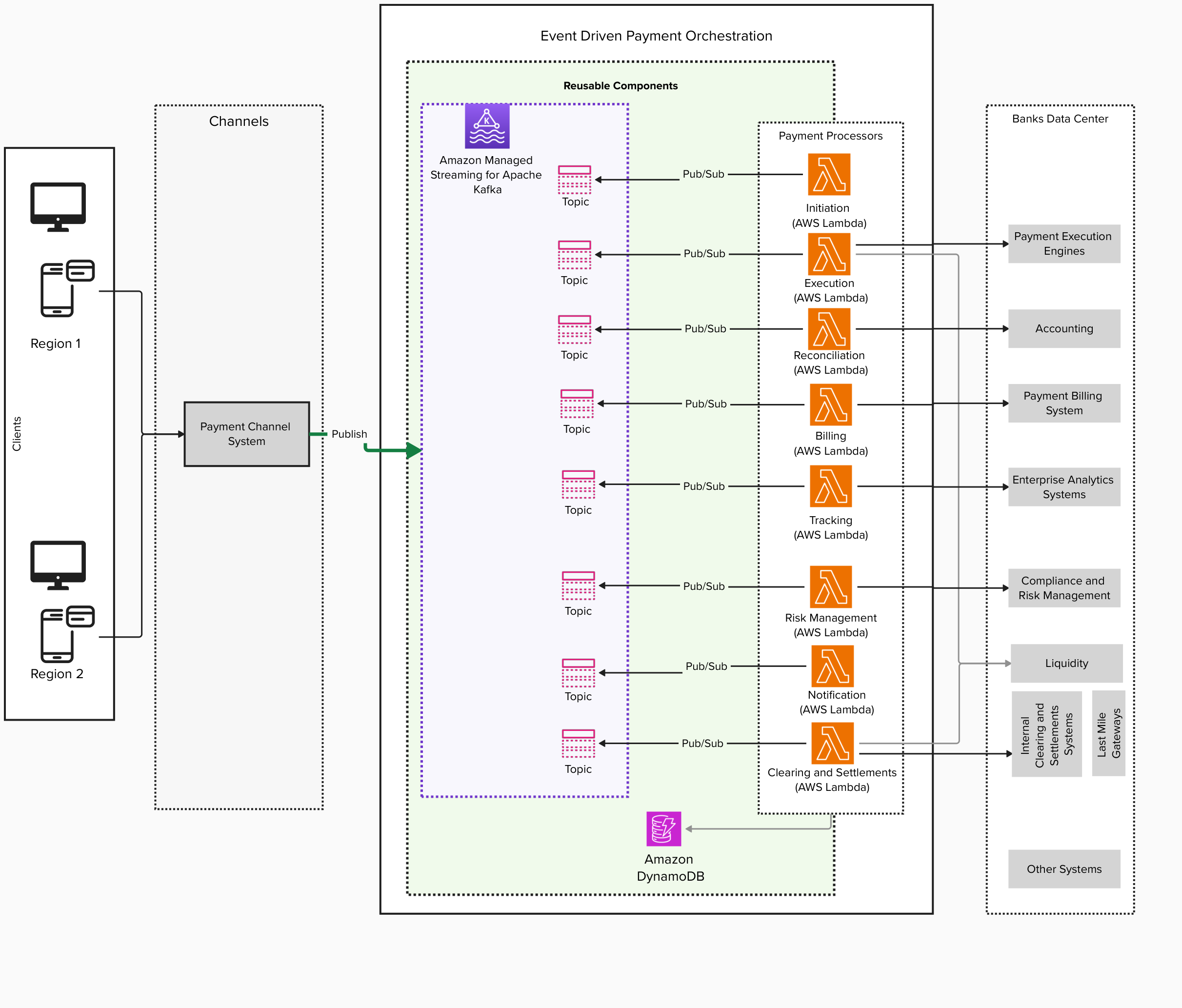
The architecture for using TwelveLabs Embed API and OpenSearch Service for advanced video search consists of the following components:

  • TwelveLabs Embed API: This API generates 1024-dimensional vector embeddings from video content, capturing visual, audio, and textual elements.
  • OpenSearch Vector Database: Stores and indexes the video embeddings generated by TwelveLabs.
  • Secrets Manager to store secrets such as API access keys, and the Amazon OpenSearch Service username and password.
  • Integration of TwelveLabs SDK and the OpenSearch Service client to process videos, generate embeddings, and index them in OpenSearch Service.

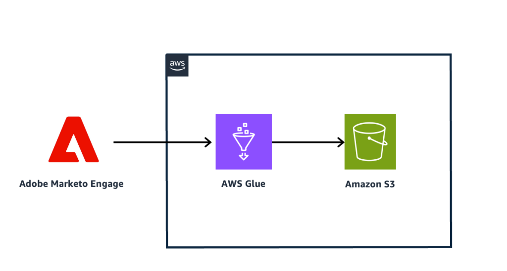
The following diagram illustrates:

  1. A video file is stored in Amazon Simple Storage Service (Amazon S3). Embeddings of the video file are created using TwelveLabs Embed API.
  2. Embeddings generated from the TwelveLabs Embed API are now ingested to Amazon OpenSearch Service.
  3. Users can search the video embeddings using text, audio, or image. The user uses TwelveLabs Embed API to create the corresponding embeddings.
  4. The user searches video embeddings in Amazon OpenSearch Service and retrieves the corresponding vector.

The use case

For the demo, you will work on these videos: Robin bird forest Video by Federico Maderno from Pixabay and Island Video by Bellergy RC from Pixabay.

However, the use case can be expanded to various other segments. For example, the news organization struggles with:

  1. Needle-in-haystack searches through thousands of hours of archival footage
  2. Manual metadata tagging that misses nuanced visual and audio context
  3. Cross-modal queries such as querying a video collection using text or audio descriptions
  4. Rapid content retrieval for breaking news tie-ins

By integrating TwelveLabs Embed API with OpenSearch Service, you can:

  • Generate 1024-dimensional embeddings capturing each video’s visual concepts. The embeddings are also capable of extracting spoken narration, on-screen text, and audio cues.
  • Enable multimodal search capabilities allowing users to:
    • Find specific demonstrations using text-based queries.
    • Locate activities through image-based queries.
    • Identify segments using audio pattern matching.
  • Reduce search time from hours to seconds for complex queries.

Solution walkthrough

GitHub repository contains a notebook with detailed walkthrough instructions for implementing advanced video search capabilities by combining TwelveLabs’ Embed API with Amazon OpenSearch Service.

Prerequisites

Before you proceed further, verify that the following prerequisites are met:

  • Confirm that you have an AWS account. Sign in to the AWS account.
  • Create a TwelveLabs account because it will be required to get the API Key. TwelveLabs offer free tier pricing but you can upgrade if necessary to meet your requirement.
  • Have an Amazon OpenSearch Service domain. If you don’t have an existing domain, you can create one using the steps outlined in our public documentation for Creating and Managing Amazon OpenSearch Service Domain. Make sure that the OpenSearch Service domain is accessible from your Python environment. You can also use Amazon OpenSearch Serverless for this use case and update the interactions to OpenSearch Serverless using AWS SDKs.

Step 1: Set up the TwelveLabs SDK

Start by setting up the TwelveLabs SDK in your Python environment:

  1. Obtain your API key from TwelveLabs Dashboard.
  2. Follow steps here to create a secret in AWS Secrets Manager. For example, name the secret as TL_API_Key.Note down the ARN or name of the secret (TL_API_Key) to retrieve. To retrieve a secret from another account, you must use an ARN.For an ARN, we recommend that you specify a complete ARN rather than a partial ARN. See Finding a secret from a partial ARN.Use this value for the SecretId in the code block below.
import boto3
import json
secrets_manager_client=boto3.client("secretsmanager")
API_secret=secrets_manager_client.get_secret_value(
SecretId="TL_API_KEY"
)
TL_API_KEY=json.loads(API_secret["SecretString"])["TL_API_Key"]

Step 2: Generate video embeddings

Use the Embed API to create multimodal embeddings that are contextual vector representations for your videos and texts. TwelveLabs video embeddings capture all the subtle cues and interactions between different modalities, including the visual expressions, body language, spoken words, and the overall context of the video, encapsulating the essence of all these modalities and their interrelations over time.

To create video embeddings, you must first upload your videos, and the platform must finish processing them. Uploading and processing videos require some time. Consequently, creating embeddings is an asynchronous process comprised of three steps:

  1. Upload and process a video: When you start uploading a video, the platform creates a video embedding task and returns its unique task identifier.
  2. Monitor the status of your video embedding task: Use the unique identifier of your task to check its status periodically until it’s completed.
  3. Retrieve the embeddings: After the video embedding task is completed, retrieve the video embeddings by providing the task identifier. Learn more in the docs.

Video processing implementation

This demo depends upon some video data. To use this, you will download two mp4 files and upload it to an Amazon S3 bucket.

  1. Click on the links containing the Robin bird forest Video by Federico Maderno from Pixabay and Island Video by Bellergy RC from Pixabay videos.
  2. Download the 21723-320725678_small.mp4 and 2946-164933125_small.mp4 files.
  3. Create an S3 bucket if you don’t have one already. Follow the steps in the Creating a bucket doc. Note down the name of the bucket and replace it the code block below (Eg., MYS3BUCKET).
  4. Upload the 21723-320725678_small.mp4 and 2946-164933125_small.mp4 video files to the S3 bucket created in the step above by following the steps in the Uploading objects doc. Note down the name of the objects and replace it the code block below (Eg., 21723-320725678_small.mp4 and 2946-164933125_small.mp4)
s3_client=boto3.client("s3")
bird_video_data=s3_client.download_file(Bucket='MYS3BUCKET',  Key='21723-320725678_small.mp4', Filename='robin-bird.mp4')
island_video_data=s3_client.download_file(Bucket='MYS3BUCKET',  Key='2946-164933125_small.mp4', Filename='island.mp4')

def print_segments(segments: List[SegmentEmbedding], max_elements: int = 1024):
    for segment in segments:
        print(
            f"  embedding_scope={segment.embedding_scope} start_offset_sec={segment.start_offset_sec} end_offset_sec={segment.end_offset_sec}"
        )
        print(f"  embeddings: {segment.embeddings_float[:max_elements]}")

# Initialize client with API key
twelvelabs_client = TwelveLabs(api_key=TL_API_KEY)

video_files=["robin-bird.mp4", "island.mp4"]
tasks=[]

Embedding generation process

With the SDK configured, generate embeddings for your video and monitor task completion with real-time updates. Here you use the Marengo 2.7 model to generate the embeddings:

for video in video_files:
    # Create embedding task
    task = twelvelabs_client.embed.task.create(
        model_name="Marengo-retrieval-2.7",
        video_file=video
    )
    print(
        f"Created task: id={task.id} engine_name={task.model_name} status={task.status}"
    )
    
    def on_task_update(task: EmbeddingsTask):
        print(f"  Status={task.status}")
    
    status = task.wait_for_done(
        sleep_interval=2,
        callback=on_task_update
    )
    print(f"Embedding done: {status}")
    
    # Retrieve and inspect results
    task = task.retrieve()
    if task.video_embedding is not None and task.video_embedding.segments is not None:
        print_segments(task.video_embedding.segments)
    tasks.append(task)

Key features demonstrated include:

  • Multimodal capture: 1024-dimensional vectors encoding visual, audio, and textual features
  • Model specificity: Using Marengo-retrieval-2.7 optimized for scientific content
  • Progress tracking: Real-time status updates during embedding generation

Expected output

Created task: id=67ca93a989d8a564e80dc3ba engine_name=Marengo-retrieval-2.7 status=processing
  Status=processing
  Status=processing
  Status=processing
  Status=processing
  Status=processing
  Status=processing
  Status=processing
  Status=processing
  Status=processing
  Status=ready
Embedding done: ready
  embedding_scope=clip start_offset_sec=0.0 end_offset_sec=6.0
  embeddings: [0.022429451, 0.00040668788, -0.01825908, -0.005862708, -0.03371106, 
-6.357456e-05, -0.015320076, -0.042556215, -0.02782445, -0.00019097517, 0.03258314, 
-0.0061399476, -0.00049206393, 0.035632476, 0.028209884, 0.02875258, -0.035486065, 
-0.11288028, -0.040782217, -0.0359422, 0.015908664, -0.021092793, 0.016303983, 
0.06351931,…………………

Step 3: Set up OpenSearch

To enable vector search capabilities, you first need to set up an OpenSearch client and test the connection. Follow these steps:

Install the required libraries

Install the necessary Python packages for working with OpenSearch:

!pip install opensearch-py
!pip install botocore
!pip install requests-aws4auth

Configure the OpenSearch client

Set up the OpenSearch client with your host details and authentication credentials:

from opensearchpy import OpenSearch, RequestsHttpConnection, helpers
from requests_aws4auth import AWS4Auth
from requests.auth import HTTPBasicAuth

# OpenSearch connection configuration
# host = 'your-host.aos.us-east-1.on.aws'
host = 'search-new-domain-mbgs7wth6r5w6hwmjofntiqcge.aos.us-east-1.on.aws'
port = 443  # Default HTTPS port

# Get OpenSearch username secret from Secrets Manager
opensearch_username=secrets_manager_client.get_secret_value(
    SecretId="AOS_username"
)
opensearch_username_string=json.loads(opensearch_username["SecretString"])["AOS_username"]

# Get OpenSearch password secret from Secrets Manager
opensearch_password = secrets_manager_client.get_secret_value(
    SecretId="AOS_password"
)
opensearch_password_string=json.loads(opensearch_password["SecretString"])["AOS_password"]

auth=(opensearch_username_string, opensearch_password_string)

# Create the client configuration
client_aos = OpenSearch(
    hosts=[{'host': host, 'port': port}],
    http_auth=auth,
    use_ssl=True,
    verify_certs=True,
    connection_class=RequestsHttpConnection
)

# Test the connection
try:
    # Get cluster information
    cluster_info = client_aos.info()
    print("Successfully connected to OpenSearch")
    print(f"Cluster info: {cluster_info}")
except Exception as e:
    print(f"Connection failed: {str(e)}")

Expected output

If the connection is successful, you should see a message like the following:

Successfully connected to OpenSearch
Cluster info: {'name': 'bb36e8d98ee7bd517891ecd714bfb9d7', ...}

This confirms that your OpenSearch client is properly configured and ready for use.

Step 4: Create an index in OpenSearch Service

Next, you create an index optimized for vector search to store the embeddings generated by the TwelveLabs Embed API.

Define the index configuration

The index is configured to support k-nearest neighbor (kNN) search with a 1024-dimensional vector field. You will these values for this demo but follow these best practices to find appropriate values for your application. Here’s the code:

# Define the enhanced index configuration
index_name = 'twelvelabs_index'
new_vector_index_definition = {
    "settings": {
        "index": {
            "knn": "true",
            "number_of_shards": 1,
            "number_of_replicas": 0
        }
    },
    "mappings": {
        "properties": {
            "embedding_field": {
                "type": "knn_vector",
                "dimension": 1024
            },
            "video_title": {
                "type": "text",
                "fields": {
                    "keyword": {
                        "type": "keyword"
                    }
                }
            },
            "segment_start": {
                "type": "date"
            },
            "segment_end": {
                "type": "date"
            },
            "segment_id": {
                "type": "text"
            }
        }
    }
}

Create the Index

Use the following code to create the index in OpenSearch Service:

# Create the index in OpenSearch
response = client_aos.indices.create(index=index_name, body=new_vector_index_definition, ignore=400)

# Retrieve and display index details to confirm creation
index_info = client_aos.indices.get(index=index_name)
print(index_info)

Expected output

After running this code, you should see details of the newly created index. For example:

{'twelvelabs_index': {'aliases': {}, 'mappings': {'properties': {'embedding_field': {'type': 'knn_vector', 'dimension': 1024}}}, 'settings': {...}}}

The following screenshot confirms that an index named twelvelabs_index has been successfully created with a knn_vector field of dimension 1024 and other specified settings. With these steps completed, you now have an operational OpenSearch Service domain configured for vector search. This index will serve as the repository for storing embeddings generated from video content, enabling advanced multimodal search capabilities.

Step 5: Ingest embeddings to the created index in OpenSearch Service

With the TwelveLabs Embed API successfully generating video embeddings and the OpenSearch Service index configured, the next step is to ingest these embeddings into the index. This process helps ensure that the embeddings are stored in OpenSearch Service and made searchable for multimodal queries.

Embedding ingestion process

The following code demonstrates how to process and index the embeddings into OpenSearch Service:

from opensearchpy.helpers import bulk

def generate_actions(tasks, video_files):
    count = 0
    for task in tasks:
        # Check if video embeddings are available
        if task.video_embedding is not None and task.video_embedding.segments is not None:
            embeddings_doc = task.video_embedding.segments
            
            # Generate actions for bulk indexing
            for doc_id, elt in enumerate(embeddings_doc):
                yield {
                    '_index': index_name,
                    '_id': doc_id,
                    '_source': {
                        'embedding_field': elt.embeddings_float,
                        'video_title': video_files[count],
                        'segment_start': elt.start_offset_sec,
                        'segment_end': elt.end_offset_sec,
                        'segment_id': doc_id
                    }
                }
        print(f"Prepared bulk indexing data for task {count}")
        count += 1

# Perform bulk indexing
try:
    success, failed = bulk(client_aos, generate_actions(tasks, video_files))
    print(f"Successfully indexed {success} documents")
    if failed:
        print(f"Failed to index {len(failed)} documents")
except Exception as e:
    print(f"Error during bulk indexing: {e}")

Explanation of the code

  1. Embedding extraction: The video_embedding.segments object contains a list of segment embeddings generated by the TwelveLabs Embed API. Each segment represents a specific portion of the video.
  2. Document creation: For each segment, a document is created with a key (embedding_field) that stores its 1024-dimensional vector, video_title with the title of the video, segment_start and segment_end indicating the timestamp of the video segment, and a segment_id.
  3. Indexing in OpenSearch: The index() method uploads each document to the twelvelabs_index created earlier. Each document is assigned a unique ID (doc_id) based on its position in the list.

Expected output

After the script runs successfully, you will see:

  • A printed list of embeddings being indexed.
  • A confirmation message:
Prepared bulk indexing data for task 0
Prepared bulk indexing data for task 1
Successfully indexed 6 documents

Result

At this stage, all video segment embeddings are now stored in OpenSearch and ready for advanced multimodal search operations, such as text-to-video or image-to-video queries. This sets up the foundation for performing efficient and scalable searches across your video content.

Step 6: Perform vector search in OpenSearch Service

After embeddings are generated, you use it as a query vector to perform a kNN search in the OpenSearch Service index. Below are the functions to perform vector search and format the search results:

# Function to perform vector search
def search_similar_segments(query_vector, k=5):
    query = {
        "size": k,
        "_source": ["video_title", "segment_start", "segment_end", "segment_id"],
        "query": {
            "knn": {
                "embedding_field": {
                    "vector": query_vector,
                    "k": k
                }
            }
        }
    }
    
    response = client_aos.search(
        index=index_name,
        body=query
    )

    results = []
    for hit in response['hits']['hits']:
        result = {
            'score': hit['_score'],
            'title': hit['_source']['video_title'],
            'start_time': hit['_source']['segment_start'],
            'end_time': hit['_source']['segment_end'],
            'segment_id': hit['_source']['segment_id']
        }
        results.append(result)

    return (results)

# Function to format search results
def print_search_results(results):
    print("\nSearch Results:")
    print("-" * 50)
    for i, result in enumerate(results, 1):
        print(f"\nResult {i}:")
        print(f"Video: {result['title']}")
        print(f"Time Range: {result['start_time']} - {result['end_time']}")
        print(f"Similarity Score: {result['score']:.4f}")

Key points:

  • The _source field contains the video title, segment start, segment end, and segment id corresponding to the video embeddings.
  • The embedding_field in the query corresponds to the field where video embeddings are stored.
  • The k parameter specifies how many top results to retrieve based on similarity.

Step 7:Performing text-to-video search

You can use text-to-video search to retrieve video segments that are most relevant to a given textual query. In this solution, you will do this by using TwelveLabs’ text embedding capabilities and OpenSearch’s vector search functionality. Here’s how you can implement this step:

Generate text embeddings

To perform a search, you first need to convert the text query into a vector representation using the TwelveLabs Embed API:

from typing import List
from twelvelabs.models.embed import SegmentEmbedding

def print_segments(segments: List[SegmentEmbedding], max_elements: int = 1024):
    for segment in segments:
        print(
            f"  embedding_scope={segment.embedding_scope} start_offset_sec={segment.start_offset_sec} end_offset_sec={segment.end_offset_sec}"
        )
        print(f"  embeddings: {segment.embeddings_float[:max_elements]}")

# Create text embeddings for the query
text_res = twelvelabs_client.embed.create(
    model_name="Marengo-retrieval-2.7",
    text="Bird eating food",  # Replace with your desired query
)

print("Created a text embedding")
print(f" Model: {text_res.model_name}")

# Extract and inspect the generated text embeddings
if text_res.text_embedding is not None and text_res.text_embedding.segments is not None:
    print_segments(text_res.text_embedding.segments)

vector_search = text_res.text_embedding.segments[0].embeddings_float
print("Generated Text Embedding Vector:", vector_search)

Key points:

  • The Marengo-retrieval-2.7 model is used to generate a dense vector embedding for the query.
  • The embedding captures the semantic meaning of the input text, enabling effective matching with video embeddings.

Perform vector search in OpenSearch Service

After the text embedding is generated, you use it as a query vector to perform a kNN search in the OpenSearch index:

# Define the vector search query
query_vector = vector_search
text_to_video_search = search_similar_segments(query_vector)
# print(text_video_search)
print_search_results(text_to_video_search)

Expected output

The following illustrates similar results retrieved from OpenSearch.

Search Results:
--------------------------------------------------

Result 1:
Video: robin-bird.mp4
Time Range: 18.0 - 21.087732
Similarity Score: 0.4409

Result 2:
Video: robin-bird.mp4
Time Range: 12.0 - 18.0
Similarity Score: 0.4300

Result 3:
Video: island.mp4
Time Range: 0.0 - 6.0
Similarity Score: 0.3624

Insights from results

  • Each result includes a similarity score indicating how closely it matches the query, a time range indicating the start and end offset in seconds, and the video title.
  • Observe that the top 2 results correspond to the robin bird video segments matching the Bird eating food query.

This process demonstrates how textual queries such as Bird eating food can effectively retrieve relevant video segments from an indexed library using TwelveLabs’ multimodal embeddings and OpenSearch’s powerful vector search capabilities.

Step 8: Perform audio-to-video search

You can use audio-to-video search to retrieve video segments that are most relevant to a given audio input. By using TwelveLabs’ audio embedding capabilities and OpenSearch’s vector search functionality, you can match audio features with video embeddings in the index. Here’s how to implement this step:

Generate audio embeddings

To perform the search, you first convert the audio input into a vector representation using the TwelveLabs Embed API:

# Create audio embeddings for the input audio file
audio_res = twelvelabs_client.embed.create(
    model_name="Marengo-retrieval-2.7",
    audio_file="audio-data.mp3",  # Replace with your desired audio file
)

# Print details of the generated embedding
print(f"Created audio embedding: model_name={audio_res.model_name}")
print(f" Model: {audio_res.model_name}")

# Extract and inspect the generated audio embeddings
if audio_res.audio_embedding is not None and audio_res.audio_embedding.segments is not None:
    print_segments(audio_res.audio_embedding.segments)

# Store the embedding vector for search
vector_search = audio_res.audio_embedding.segments[0].embeddings_float
print("Generated Audio Embedding Vector:", vector_search)

Key points:

  • The Marengo-retrieval-2.7 model is used to generate a dense vector embedding for the input audio.
  • The embedding captures the semantic features of the audio, such as rhythm, tone, and patterns, enabling effective matching with video embeddings

Perform vector search in OpenSearch Service

After the audio embedding is generated, you use it as a query vector to perform a k-nearest neighbor (kNN) search in OpenSearch:

# Perform vector search
query_vector = vector_search
audio_to_video_search = search_similar_segments(query_vector)
# print(text_video_search)
    
print_search_results(audio_to_video_search)

Expected output

The following shows video segments retrieved from OpenSearch Service based on their similarity to the input audio.

Search Results:
--------------------------------------------------

Result 1:
Video: island.mp4
Time Range: 6.0 - 12.0
Similarity Score: 0.2855

Result 2:
Video: robin-bird.mp4
Time Range: 18.0 - 21.087732
Similarity Score: 0.2841

Result 3:
Video: robin-bird.mp4
Time Range: 12.0 - 18.0
Similarity Score: 0.2837

Result 4:
Video: island.mp4
Time Range: 0.0 - 6.0
Similarity Score: 0.2835

Here notice that segments from both videos are returned with a low similarity score.

Step 9: Performing images-to-video search

You can use image-to-video search to retrieve video segments that are visually similar to a given image. By using TwelveLabs’ image embedding capabilities and OpenSearch Service’s vector search functionality, you can match visual features from an image with video embeddings in the index. Here’s how to implement this step:

Generate Image Embeddings

To perform the search, you first convert the input image into a vector representation using the TwelveLabs Embed API:

# Create image embeddings for the input image file
image_res = twelvelabs_client.embed.create(
    model_name="Marengo-retrieval-2.7",
    image_file="image-data.jpg",  # Replace with your desired image file
)

# Print details of the generated embedding
print(f"Created image embedding: model_name={image_res.model_name}")
print(f" Model: {image_res.model_name}")

# Extract and inspect the generated image embeddings
if image_res.image_embedding is not None and image_res.image_embedding.segments is not None:
    print_segments(image_res.image_embedding.segments)

# Store the embedding vector for search
vector_search = image_res.image_embedding.segments[0].embeddings_float
print("Generated Image Embedding Vector:", vector_search)

Key points:

  • The Marengo-retrieval-2.7 model is used to generate a dense vector embedding for the input image.
  • The embedding captures visual features such as shapes, colors, and patterns, enabling effective matching with video embeddings

Perform vector search in OpenSearch

After the image embedding is generated, you use it as a query vector to perform a k-nearest neighbor (kNN) search in OpenSearch:

# Perform vector search
query_vector = vector_search
image_to_video_search = search_similar_segments(query_vector)
# print(text_video_search)
    
print_search_results(image_to_video_search)

Expected output

The following shows video segments retrieved from OpenSearch based on their similarity to the input image.

Search Results:
--------------------------------------------------

Result 1:
Video: island.mp4
Time Range: 6.0 - 12.0
Similarity Score: 0.5616

Result 2:
Video: island.mp4
Time Range: 0.0 - 6.0
Similarity Score: 0.5576

Result 3:
Video: robin-bird.mp4
Time Range: 12.0 - 18.0
Similarity Score: 0.4592

Result 4:
Video: robin-bird.mp4
Time Range: 18.0 - 21.087732
Similarity Score: 0.4540

Observe that image of an ocean was used to search the videos. Video clips from the island video are retrieved with a higher similarity score in the first 2 results.

Clean up

To avoid charges, delete resources created while following this post. For Amazon OpenSearch Service domains, navigate to the AWS Management Console for Amazon OpenSearch Service dashboard and delete the domain.

Conclusion

The integration of TwelveLabs Embed API with OpenSearch Service provides a cutting-edge solution for advanced video search and analysis, unlocking new possibilities for content discovery and insights. By using TwelveLabs’ multimodal embeddings, which capture the intricate interplay of visual, audio, and textual elements in videos, and combining them with OpenSearch Service’s robust vector search capabilities, this solution enables highly nuanced and contextually relevant video search.

As industries increasingly rely on video content for communication, education, marketing, and research, this advanced search solution becomes indispensable. It empowers businesses to extract hidden insights from their video content, enhance user experiences in video-centric applications and make data-driven decisions based on comprehensive video analysis

This integration not only addresses current challenges in managing video content but also lays the foundation for future innovations in how we interact with and derive value from video data.

Get started

Ready to explore the power of TwelveLabs Embed API? Start your free trial today by visiting TwelveLabs Playground to sign up and receive your API key.

For developers looking to implement this solution, follow our detailed step-by-step guide on GitHub to integrate TwelveLabs Embed API with OpenSearch Service and build your own advanced video search application.

Unlock the full potential of your video content today!


About the Authors

James Le runs the Developer Experience function at TwelveLabs. He works with partners, developers, and researchers to bring state-of-the-art video foundation models to various multimodal video understanding use cases.

Gitika is an Senior WW Data & AI Partner Solutions Architect at Amazon Web Services (AWS). She works with partners on technical projects, providing architectural guidance and enablement to build their analytics practice.

Kruthi is a Senior Partner Solutions Architect specializing in AI and ML. She provides technical guidance to AWS Partners in following best practices to build secure, resilient, and highly available solutions in the AWS Cloud.

Deploy real-time analytics with StarTree for managed Apache Pinot on AWS

Post Syndicated from Raj Ramasubbu original https://aws.amazon.com/blogs/big-data/deploy-real-time-analytics-with-startree-for-managed-apache-pinot-on-aws/

This post is cowritten with Mayank Shrivastava and Barkha Herman from StarTree.

Building a low-latency, high-concurrency, real-time online analytical processing (OLAP) solution has been previously explored on the AWS Big Data Blog, where we walked through how to build a real-time analytics solution with Apache Pinot on AWS, in which streaming sources, such as Amazon Managed Streaming for Apache Kafka (Amazon MSK) and Amazon Kinesis Data Streams, produce events that are ingested and processed in real time within Apache Pinot.

However, this approach requires self-management of the infrastructure required to run Pinot, as well as a number of manual processes to run in production. StarTree is a managed alternative that offers similar benefits for real-time analytics use cases.

In this post, we introduce StarTree as a managed solution on AWS for teams seeking the advantages of Pinot. We highlight the key distinctions between open-source Pinot and StarTree, and provide valuable insights for organizations considering a more streamlined approach to their real-time analytics infrastructure.

By examining these aspects, you can make an informed decision between open source Pinot and StarTree for your specific real-time analytics needs.

StarTree overview

One of the founders of Apache Pinot, Kishore Gopalakrishna, launched StarTree to equip organizations globally with the power of real-time data and build a fully managed platform for real-time analytics. Handling over 1 billion queries per week and ingesting over 1 million events per second, StarTree Cloud removes the burden of infrastructure management so companies can focus on delivering real-time insights to end-users.

Open source Pinot requires in-house expertise that can challenge well-established technical teams to provision hardware, configure environments, tune performance, maintain security, adhere to data governance requirements, manage software updates, and constantly monitor for system issues. Organizations interested in decreasing their time to value with a managed Pinot solution can take advantage of the expertise of StarTree’s team to accelerate setup, deploy an architecture ready for scale, and offload infrastructure maintenance.

Improving security with SOC 2, SSO, and RBAC

Critical enterprise security features can be challenging to implement in open source Pinot environments. With StarTree’s managed Pinot, role-based access control (RBAC) simplifies administration for Pinot and allows organizations to assign and monitor user access based on roles to enforce secure and efficient access to sensitive data. StarTree Cloud provides enterprise-grade security with SOC 2 compliance, enhanced encryption, and single sign-on (SSO) capabilities.

Using automated data ingestion at scale

The minion task framework is a native component of Pinot to offload computationally intensive tasks away from the other Pinot components to conserve resources for low-latency queries and support real-time stream ingestion. StarTree can handle larger volumes of data efficiently with highly scalable implementations of minion tasks and a minion auto scaling feature that eliminates unnecessary infrastructure costs during idle times, as seen in the below figure.

StarTree’s automatic data ingestion framework is ideal for enterprise workloads because it improves scalability and reduces the data maintenance complexity often found in open source Pinot deployments. StarTree supports a large number of managed connectors, which are used to maintain metadata about the source and ingest data seamlessly into the platform. The data is then modelled to help you organize and structure the data fetched from the selected data source into Pinot tables. Indexes are then configured to optimize query performance, as per the flow in the diagram below.

Tiered storage for real-time query processing

With open source Pinot, tiered storage can be used for deep storage like Amazon Simple Storage Service (Amazon S3) for backup but not query processing, because storage is tightly coupled with compute and requires manual configuration of tenants with different storage speeds and server specifications. In the following diagram, an Amazon S3 tier is defined for the data to be moved from tightly coupled SSD to cloud storage when the data is 30 days old.


On the other hand, StarTree transitions less-frequently accessed data to cost-effective storage like Amazon S3, while maintaining quick access to frequently accessed data. StarTree’s tiered storage enables automation for real-time query processing with index pinning, prefetching, and intelligent data movement between hot and cold storage, optimizing both performance and cost. StarTree’s sophisticated approach to tiered storage is highly flexible and reduces replication overhead by keeping a single copy in cloud storage, which prevents the limitations of compressed deep store copies, as you can see in the below diagram

Improving scalability with off-heap upserts

Companies like Amberdata benefit from StarTree’s upsert support to routinely upsert 350,000 events per second, with peak workloads reaching 1 million upserts per second. StarTree Cloud enhanced upsert functionality boosts efficiency, usability, and scalability through the implementation of off-heap upserts. Behind the scenes, Pinot servers manage specific upsert metadata to determine if a newly inserted record’s primary key was previously encountered and identifies the current segment holding it. As shown below, StarTree Cloud moves this off-heap, enabling a scalable cache of metadata as the on-heap memory restrictions are removed

Customer success stories using Pinot with StarTree for real-time analytics

The following customers highlight their success using Pinot for StarTree:

Flexible deployment options for StarTree Cloud

StarTree offers multiple deployment options, including a StarTree hosted software as a service (SaaS) or customer hosted SaaS. StarTree hosted SaaS is ideal for organizations interested in fully offloading the operational burden of infrastructure management, scaling, performance tuning, and security from their team so they can focus on analytics. StarTree’s customer hosted SaaS provides flexibility for customers interested in deploying the solution within their AWS environment or other platform of choice. This is suitable for organizations who require higher infrastructure management controls in their perimeter but still want the operational ease of a managed service.

Self-managed Pinot or StarTree

Pinot can deliver value for real-time analytics scenarios with different deployment methods. The choice of deployment method will come down to organizational priorities and trade-offs. Teams with the capability and willingness to manage open source software on a commodity infrastructure at scale might opt to deploy self-managed Pinot on AWS. Teams interested in reducing time troubleshooting performance bottlenecks, optimizing resource usage, and minimizing downtime can use StarTree’s managed service.

Conclusion

In this post, we presented StarTree as a managed solution on AWS for teams seeking the advantages of Apache Pinot. Like Pinot, StarTree addresses the need for a low-latency, high-concurrency, real-time online analytical processing (OLAP) solution. In addition, StarTree offers a managed experience for real-time and batch Pinot workloads, offering enhanced security, automated data ingestion, tiered storage, and off-heap upserts. These features improve security, scalability, and manageablity for organizations looking to run Pinot in production.

Developers interested in learning more about managed Pinot can deploy real-time analytics with StarTree to test it out or join a session with StarTree’s head of product. StarTree is an AWS ISVA partner and is available on AWS Marketplace.


About the Authors

Raj Ramasubbu is a Senior Analytics Specialist Solutions Architect focused on big data and analytics and AI/ML with Amazon Web Services. He helps customers architect and build highly scalable, performant, and secure cloud-based solutions on AWS. Raj provided technical expertise and leadership in building data engineering, big data analytics, business intelligence, and data science solutions for over 18 years prior to joining AWS. He helped customers in various industry verticals like healthcare, medical devices, life science, retail, asset management, car insurance, residential REIT, agriculture, title insurance, supply chain, document management, and real estate.

Francisco Morillo is a Streaming Solutions Architect at AWS. Francisco works with AWS customers, helping them design real-time analytics architectures using AWS services, supporting Amazon Managed Streaming for Apache Kafka (Amazon MSK) and Amazon Managed Service for Apache Flink.

Ismail Makhlouf is a Senior Specialist Solutions Architect for Data Analytics at AWS. Ismail focuses on architecting solutions for organizations across their end-to-end data analytics estate, including batch and real-time streaming, big data, data warehousing, and data lake workloads. He primarily partners with airlines, manufacturers, and retail organizations to support them to achieve their business objectives with well-architected data platforms.

Renee Berry is a Senior Partner Development Manager with the AWS Global Startup Program, working with venture backed startups partnering with AWS to scale their growth.

Mayank Shrivastava is a founding engineer of Apache Pinot and a PMC member for the project. He is currently a Fellow at StarTree Inc., where he also heads their Center of Excellence.

Barkha Herman is a technologist and developer advocate who founded WiTVoices and South Florida Women in Tech. She fosters inclusive tech communities.

Enhancing Adobe Marketo Engage Data Analysis with AWS Glue Integration

Post Syndicated from Kenny Rajan original https://aws.amazon.com/blogs/big-data/enhancing-adobe-marketo-engage-data-analysis-with-aws-glue-integration/

Today’s digital-first, B2B landscape presents marketers with complex challenges as they navigate sophisticated buyer journeys involving diverse decision-making groups. Adobe Marketo Engage offers a comprehensive marketing hub for orchestrating cross-channel campaigns. Using AI-driven personalization, automation, and real-time analytics, it helps businesses acquire and retain customers throughout their buying journeys. Marketo Engage empowers B2B marketers to navigate modern complexities and successfully drive measurable business growth through multi-channel engagement, automated customer journeys, and sales-marketing collaboration.

To further enhance their B2B marketing capabilities, organizations are now looking to fully use their marketing data for more informed decision-making and strategy optimization. Recognizing the need to simplify the analytics pipeline, AWS introduced software as a service (SaaS) connectivity for Marketo Engage through AWS Glue, delivering insights faster to enable data-driven decisions. The agile, serverless nature of AWS Glue meets a range of data analytics needs while reducing costs. This powerful integration links the robust marketing automation features of Marketo Engage with AWS’s advanced analytics ecosystem. By seamlessly connecting the platforms, businesses can extract greater value from marketing data, gaining deeper insights into customer behavior and campaign performance. Together, AWS Glue and Marketo Engage unlock new possibilities for data-driven marketing:

  • Marketing-sales alignment – Helps automate the transfer of lead and opportunity data between Marketo Engage and CRM systems, making sure that sales and marketing teams are aligned and responsive to customer needs
  • Enhanced analytics – Connects Marketo Engage with business intelligence (BI) tools for data-driven campaign optimization, allowing marketers to extract meaningful insights and make informed decisions
  • Data integrity – Maintains consistent, high-quality data across all systems, providing reliability and accuracy in marketing and sales operations
  • Improved lead quality – Refines lead scoring processes by using the advanced analytics capabilities of AWS, resulting in better-qualified leads and improved sales conversions
  • Unified customer view – Provides comprehensive customer insights using enriched AWS datasets for Marketo Engage, offering a holistic understanding of customer interactions and behaviors

In this post, we show you how to use AWS Glue to extract data from Marketo Engage for data processing and enrichment on AWS for use in marketing analytics workflows.

Solution Overview

We explore a use case in which a company wants to run analysis for campaign leads in multiple countries. The resulting leads will be shared with the respective regional marketing representatives. The solution uses AWS Glue to extract data from Marketo Engage and save it in an Amazon Simple Storage Service (Amazon S3) bucket. The following diagram illustrates the solution architecture.

1_Scope-of-the-solutions_AWSGLue_Marketo_Engage_Flow

In the following sections, we walk through the high-level steps to implement the solution:

  1. Create AWS resources to connect to Marketo Engine and store data.
  2. Create an AWS Glue connection.
  3. Create an extract, transform, and load (ETL) job using AWS Glue Studio.
  4. Analyze the data.

Prerequisites

To set up the integration between Marketo Engage and AWS, the following components are required:

  • A Marketo Engage account – If you don’t already have one, create a Marketo Engage application and record the Munchkin ID, client ID, and client secret for the application. Refer to the Marketo Engage developer portal to set up the connection.
  • An AWS Glue database – This will serve as the data interaction interface on AWS. The database will expose the data residing in Amazon S3 as queryable AWS Glue tables. For this post, our database is called marketodb.

Create AWS resources to connect to Marketo Engage and store data

We use an AWS CloudFormation template to create an S3 bucket to store data, an AWS Secrets Manager secret for Marketo Engage that the AWS Glue connection needs, and an AWS Identity and Access Management (IAM) role to access the secret. Complete the following steps:

  1. Click Launch Stack below.
    Click here to launch the Cloud Fromation stack
  2. On the Specify stack details page, enter a name for the stack.
  3. Specify the Marketo client secret.
  4. Choose Next.
  5. On the Configure stack options page, choose Next.
  6. On the Review page, select I acknowledge that AWS CloudFormation might create IAM resources.
  7. Choose Submit. Note: The stack takes about 2 minutes to deploy.
  8. After the stack is created, make a note of the S3AccessRoleARN You will need this to create the Marketo Engage connection.

Create an AWS Glue connection

Complete the following steps to create an AWS Glue connection:

  1. On the AWS Glue console, choose Data connections in the navigation pane.
  2. Choose Create connection.
  3. For Data sources, select Marketo.

2-Glue-Data-Source-page

  1. Enter the Adobe MUNCHKIN_ID.
  2. Choose the IAM role created in the previous section as the AWS Glue connection IAM service role.
  3. Provide the Adobe ClientId as the user-managed client application client ID.
  4. Provide the Secrets Manager secret you created earlier.
  5. Choose Next.
  6. Specify your preferred connection name.
  7. Choose Next.
  8. Review the settings, then choose Create connection.

Entering-Marketo-Connectiondetails-in-glue.jpg

Create an ETL job using AWS Glue Studio

Complete the following steps to create an ETL job:

  1. On the AWS Glue console, choose ETL jobs in the navigation pane.
  2. Choose Create job.
  3. Choose Visual ETL.
  4. Add Marketo as a source node.
  5. Add Amazon S3 as the target node.
    Selecting Source Adobe Marketo Engage as Target and Amazon S3 as the target node in the AWS glue Visual Flow
  1. Choose the Marketo Engage data source node, and the editor will show a configuration pane on the right side of the diagram.
  2. In the Data source properties pane, provide the following information:
    1. For Name, enter a name (for example, Marketo).
    2. For Marketo connection, choose your Marketo Engage connection.
    3. For Entity Name, choose Leads as the entity to retrieve from Marketo Engage.
    4. For Fields, choose All Fields as the fields to retrieve from Marketo Engage.
    5. For Filter, enter gender=’Male’ to pull leads according to the campaign criteria. Note that in this blog post you’re using a synchronous mode in which the Marketo Adobe API limits require that the retrieved data set is less that 1000. See the AWS documentation to apply the criteria and mechanisms that support your campaigns.

You can observe the data preview pane reflecting the modifications you have made.

5-Entering-Marketo-Source-Properties-in-glue

  1. Choose the Amazon S3 target node to configure it.
  2. In the Data target properties pane, provide the following information:
    1. For Name, enter a name (for example, Amazon S3).
    2. For Node parents¸ choose Marketo.
    3. For Format, choose Parquet.
    4. For Compression Type¸ choose Snappy.
    5. For S3 Target Location, enter the path to the S3 bucket you created earlier, and optionally specify a prefix. This will inform the ETL job where to store the data retrieved from Marketo Engage.
    6. For Data Catalog update options, select Create a table in the Data Catalog and on subsequent runs, update the schema and add new partitions.
    7. For Database, choose your database in the AWS Glue Data Catalog.
    8. For Table name, enter a table name for the Data Catalog (for example, marketo_leads).

After you configure the source and target nodes, both nodes in the Visual ETL Editor should have a green check mark, indicating they are correctly configured.

  1. Specify the name for the job and save it.
  2. When the job is saved, choose Run to invoke the ETL job.
  3. After the job starts, go to the Runs tab and observe the run until completion.

Depending on the size of the data in your account object in Marketo Engage, the job will take a few minutes to complete. After a successful job run, a new table called marketo_leads is created and populated with data from Marketo Engage.

Analyze the data

After a successful run, you can now use Amazon Athena analyze the data from Marketo Engage with the data residing on AWS. If you’re using Athena for the first time, refer to Create a query output location for instructions to set up the query editor. Then run the following query:

SELECT country, COUNT(*) as count FROM marketo_leads GROUP BY country ORDER BY country;

The query will output the number of people within each country who can be contacted as targeting leads for campaigns, and you can enrich this output by adding other datasets in your data lake or data warehouse. You can expect to see an output like the following screenshot.

Executing Query to find campaign information using Marketo Engage data

Clean up

To avoid incurring charges, clean up the resources in your AWS account by completing the following steps:

  1. Delete the table created from the Data Catalog:
    1. On the AWS Glue console, navigate to the Data Catalog.
    2. Select the table and choose Delete.
  2. Delete the ETL job:
    1. On the AWS Glue console, choose ETL jobs in the navigation pane.
    2. From the list of jobs, select the job you created, and on the Actions menu, choose Delete.
  3. Delete the data connection:
    1. On the AWS Glue console, choose Data connections in the navigation pane.
    2. Select the Marketo Engage connection from the list of connectors, and on the Actions menu, choose Delete.
  4. Delete the CloudFormation stack:
    1. On the CloudFormation console, choose Stacks in the navigation pane.
    2. Select the stack you created for the S3 bucket and related resources and delete it.

Conclusion

The AWS Glue connector for Marketo Engage streamlines data integration, permitting seamless data synchronization between Marketo Engage and AWS services for a holistic view of customer information. This powerful integration enhances the capacity for advanced analytics, enabling marketers to glean precise and insightful learnings from their data; these insights can then be used to inform and refine marketing strategies, boosting campaign performance and driving better business outcomes

For more information on the AWS Glue connector for Marketo Engage and AWS Glue, refer to the relevant user guides and visit the AWS Glue website.


About the Authors

Kenny Rajan is a Principal Enterprise Architect at AWS specializing in integrating generative AI with enterprise systems like SAP and Adobe. He helps organizations modernize their digital experience platforms and supply chain and back-end systems through data and AI-powered cloud solutions. Outside of work, he contributes to technology education and charitable initiatives.

Author Rafael Profile PictureRafał Pawłaszek is a Senior Cloud Application Architect at AWS. Rafał supports customer transformation to the cloud and customer enablement in the cloud. Outside of work, he is interested in astronomy, astrophysics, and psychology, and loves spending time with family.

Author Basher Profile PictureBasheer Sheriff is a Senior Solutions Architect at AWS. He loves to help customers solve interesting problems using new technology. He is based in Melbourne, Australia, and likes to play sports such as football and cricket.

Author Kamen Profile PictureKamen Sharlandjiev is a Sr. Big Data Solutions Architect, Amazon MWAA and AWS Glue ETL expert. He’s on a mission to make life easier for customers who are facing complex data integration and orchestration challenges. His secret weapon? Fully managed AWS services that can get the job done with minimal effort. Follow Kamen on LinkedIn to keep up to date with the latest Amazon MWAA and AWS Glue features and news!

Building and operating data pipelines at scale using CI/CD, Amazon MWAA and Apache Spark on Amazon EMR by Wipro

Post Syndicated from Senaka Ariyasinghe original https://aws.amazon.com/blogs/big-data/building-and-operating-data-pipelines-at-scale-using-ci-cd-amazon-mwaa-and-apache-spark-on-amazon-emr-by-wipro/

Businesses of all sizes are challenged with the complexities and constraints posed by traditional extract, transform and load (ETL) tools. These intricate solutions, while powerful, often come with a significant financial burden, particularly for small and medium enterprise customers. Beyond the substantial costs of procurement and licensing, customers must also contend with the expenses associated with installation, maintenance, and upgrades—a perpetual cycle of investment that can strain even the most robust budgets. At Wipro, scalability of data pipelines in addition to automation remains a persistent concern for their customers and they’ve learned through customer engagements that it’s not achievable without considerable effort. As data volumes continue to swell, these tools can struggle to keep pace with the ever-increasing demand, leading to processing delays and disruptions in data delivery—a critical bottleneck in an era when timely insights are paramount.

This blog post discusses how a programmatic data processing framework developed by Wipro can help data engineers overcome obstacles and streamline their organization’s ETL processes. The framework leverages Amazon EMR improved runtime for Apache Spark and integrates with AWS Managed services.  This framework is robust and capable of connecting with multiple data sources and targets. By using capabilities from AWS managed services, the framework eliminates the undifferentiated heavy lifting typically associated with infrastructure management in traditional ETL tools, enabling customers to allocate resources more strategically. Furthermore, we will show you how the framework’s inherent scalability ensures that businesses can effortlessly adapt to increasing data volumes, fostering agility and responsiveness in an evolving digital landscape.

Solution overview

The proposed solution helps build a fully automated data processing pipeline that streamlines the entire workflow. It triggers processes when code is pushed to Git, orchestrates and schedules processing of jobs, validates data with the help of defined rules, transforms data prescribed within code, and loads the transformed datasets into a specified target. The primary component of this solution is the robust framework, developed using Amazon EMR runtime for Apache Spark. The framework can be used for any ETL process where input might be fetched from various data sources, transformed, and loaded into specified targets. To enable gaining valuable insights and provide overall job monitoring and automation, the framework is integrated with AWS managed services:

Solution walkthrough

solution architecture

The solution architecture is shown in the preceding figure and includes:

  1. Continuous integration and delivery (CI/CD) for data processing
    • Data engineers can define the underlying data processing job within a JSON template. A pre-defined template is available on GitHub for you to review syntax. At a high level, this step includes the following objectives:
      • Writing the Spark job configuration to be executed on Amazon EMR.
      • Split the data processing into three phases:
        • Parallelize fetching data from source, validate source data, and prepare the dataset for further processing.
        • Provide flexibility to write business transformation rules defined in JSON, including data validation checks such as duplicate record, null value check, and their removal. It can also include any SQL based transformation written in Apache Spark SQL.
        • Take the transformed data set and load it to the target and perform reconciliation as needed.

It’s important to highlight that each step of the three phases is recorded for auditing, and error reporting, and troubleshooting and security purposes.

    • After the data engineer has prepared the configuration file following the prescribed template in step 1 and committed it to the Git repository, it triggers the Jenkins pipeline. Jenkins is an open source continuous integration tool running on an EC2 instance that takes the configuration file, processes it, and builds (compiles the Spark application code) end artifacts—a JAR file and a configuration file (.conf) that’s copied to an S3 bucket and will be used later by Amazon EMR.
  1. CI/CD for data pipeline

The CI/CD for the data pipeline is shown in the following figure.

CICD for the data pipeline

    • After the data processing job is written, the data engineers can use a similar code-driven development approach to define the data processing pipeline to schedule, orchestrate, and execute the data processing job. Apache Airflow is a popular open source platform used for developing, scheduling, and monitoring batch-oriented workflows. In this solution, we use Amazon MWAA to execute the data pipeline through a Direct Acyclic Graph (DAG). To make it easier for engineers to build the required DAG in this solution, you can define the data pipeline in simple YAML. A sample of the YAML file is available on GitHub for review.
    • When a user commits the YAML file containing the DAG details to the project Git repository, another Jenkins pipeline is triggered.
    • The Jenkins pipeline now reads the YAML configuration file and based on the task and dependencies given, it generates the DAG script file, which is copied to the configured S3 bucket.
  1. Airflow DAG execution
    • After both the data processing job and data pipeline are configured, Amazon MWAA retrieves the most recent scripts from the S3 bucket to display the latest DAG definition in the Airflow user interface. These DAGs contain at least three tasks and except for creating and terminating an EMR cluster, every task represents an ETL process. Sample DAG code is available in GitHub. The following figure shows the DAG grid view within Amazon MWAA.

    • As defined in the schedule specified in the job, Airflow executes the create Amazon EMR task that launches the Amazon EMR cluster on the EC2 instance. After the cluster is created, the ETL processes are submitted to Amazon EMR as steps.
    • Amazon EMR executes these steps concurrently (Amazon EMR provides step concurrency levels that define how many steps to process concurrently). After the tasks are finished, the Amazon EMR cluster is terminated to save costs.
  1. ETL processing
    • Each step submitted by Airflow to Amazon EMR with a Spark submit command also includes the S3 bucket path of the configuration file passed as an argument.
    • Based on the configuration file, the input data is fetched and technical validations are applied. If data mapping has been enabled within the data processing job, then the structured data is prepared based on the given schema. This output is passed to next phase where data transformations and business validations can be applied.
    • A set of reconciliation rules are applied to the transformed data to ensure the data quality dimensions. After this step, data is loaded to specified target.

The following figure shows the ETL data processing job as executed by Amazon EMR.

ETL data processing job

  1. Logging, monitoring and notification
    • Amazon MWAA provides the logs generated by each task of the DAG within the Airflow UI. Using these logs, you can monitor Apache Airflow task details, delays, and workflow errors.
    • Amazon MWAA also frequently pings the Amazon EMR cluster to fetch the latest status of the step being executed and updates the task status accordingly.
    • If a step has failed, for example, if the database connection was not established because of high traffic, Amazon MWAA repeats the process.
    • Whenever a task has failed, an email notification is sent to the configured recipients with the failure cause and logs using Amazon SNS.

The key capabilities of this solution are:

  • Full automation: After the user commits the configuration files to Git, the remainder of the process is fully automated from when the CI/CD pipelines deploy the artifacts and DAG code. The DAG code is later executed in Airflow at the scheduled time. The entire ETL job is logged and monitored, and email notifications are sent in case of any failures.
  • Flexible integration: The application can seamlessly accommodate a new ETL process with minimal effort. To create a new process, prepare a configuration file that contains the source and target details and the necessary transformation logic. An example of how to specify your data transformation is shown in the following sample code.
    "data_transformations": [{
    "functionName": "cast column date_processed",
    "sqlQuery": "Select *, from_unixtime(UNIX_TIMESTAMP(date_processed, 'yyyy-MM-dd HH:mm:ss'), 'dd/MM/yyyy') as dateprocessed from table_details",
    "outputDFName": "table_details"
    },
    {
    "functionName": "find the reference data from lookup",
    "sqlQuery": "join_query_table_lookup.sql",
    "outputDFName": "super_search_table_details"
    }]

  • Fault tolerance: In addition to Apache Spark’s fault-tolerant capabilities, this solution offers the ability to recover data even after the Amazon EMR has been terminated. The application solution has three phases. In the event of a failure in the Apache Spark job, the output of the last successful phase is temporarily stored in Amazon S3. When the job is triggered again through Airflow DAG, the Apache Spark job will resume from the point at which it previously failed, thereby ensuring continuity and minimizing disruptions to the workflow. The following figure shows job reporting in the Amazon MWAA UI.

job reporting in the Amazon MWAA UI.

  • Scalability: As shown in the following figure, the Amazon EMR cluster is configured to use instance fleet options to scale up or down the number of nodes depending on the size of the data, which makes this application an ideal choice for businesses with growing data needs.

instance fleet options to scale up or down

  • Customizable: This solution can be customized to meet the needs of specific use cases, allowing you to add your own transformations, validations, and reconciliations according to your unique data management requirements.
  • Enhanced data flexibility: By incorporating support for multiple file formats, the Apache Spark application and Airflow DAGs gain the ability to seamlessly integrate and process data from various sources. This advantage allows data engineers to work with a wide range of file formats, including JSON, XML, Text, CSV, Parquet, Avro, and so on.
  • Concurrent execution: Amazon MWAA submits the tasks to Amazon EMR for concurrent execution, using the scalability and performance of distributed computing to process large volumes of data efficiently.
  • Proactive error notification: Email notifications are sent to configured recipients whenever a task fails, providing timely awareness of failures and facilitating prompt troubleshooting.

Considerations

In our deployments, we have noticed that the average time of a DAG completion is 15–20 minutes containing 18 ETL processes concurrently and dealing with 900 thousand to 1.2 million records each. However, if you want to further optimize the DAG completion time, you can configure the core.dag_concurrency from the Amazon MWAA console as described in Example high performance use case.

Conclusion

The proposed code-driven data processing framework developed by Wipro using Amazon EMR Runtime for Apache Spark and Amazon MWAA demonstrates a solution to address the challenges associated with traditional ETL tools. By harnessing the capabilities from open source frameworks and seamlessly integrating with AWS services, you can build cost-effective, scalable, and automated approaches for your enterprise data processing pipelines.

Now that you have seen how to use Amazon EMR Runtime for Apache Spark with Amazon MWAA , we encourage you to use Amazon MWAA to create a workflow that will run your ETL jobs on Amazon EMR Runtime for Apache Spark.

The configuration file samples and example DAG code referred in this blog post can be found in GitHub.

References

Disclaimer

Sample code, software libraries, command line tools, proofs of concept, templates, or other related technology are provided as AWS Content or third-party content under the AWS Customer Agreement, or the relevant written agreement between you and AWS (whichever applies). You should not use this AWS Content or third-party content in your production accounts, or on production or other critical data. Performance metrics, including the stated DAG completion time, may vary based on the specific deployment environment. You are responsible for testing, securing, and optimizing the AWS Content or third-party content, such as sample code, as appropriate for production grade use based on your specific quality control practices and standards. Deploying AWS Content or Third-Party Content may incur AWS charges for creating or using AWS chargeable resources, such as running Amazon EC2 instances or using Amazon S3 storage.


About the Authors

Deependra Shekhawat is a Senior Energy and Utilities Industry Specialist Solutions Architect based in Sydney, Australia. In his role, Deependra helps Energy companies across APJ region use cloud technologies to drive sustainability and operational efficiency. He specializes in creating robust data foundations and advanced workflows that enable organizations to harness the power of big data, analytics, and machine learning for solving critical industry challenges.

Senaka Ariyasinghe is a Senior Partner Solutions Architect working with Global Systems Integrators at AWS. In his role, Senaka guides AWS partners in the APJ region to design and scale well-architected solutions, focusing on generative AI, machine learning, cloud migrations, and application modernization initiatives.

Sandeep Kushwaha is a Senior Data Scientist at Wipro and has extensive experience in big data and machine learning. With a strong command of Apache Spark, Sandeep has designed and implemented cutting-edge cloud solutions that optimize data processing and drive efficiency. His expertise in using AWS services and best practices, combined with his deep knowledge of data management and automation, has enabled him to lead successful projects that meet complex technical challenges and deliver high-impact results.

Run Apache XTable in AWS Lambda for background conversion of open table formats

Post Syndicated from Matthias Rudolph original https://aws.amazon.com/blogs/big-data/run-apache-xtable-in-aws-lambda-for-background-conversion-of-open-table-formats/

This post was co-written with Dipankar Mazumdar, Staff Data Engineering Advocate with AWS Partner OneHouse.

Data architecture has evolved significantly to handle growing data volumes and diverse workloads. Initially, data warehouses were the go-to solution for structured data and analytical workloads but were limited by proprietary storage formats and their inability to handle unstructured data. This led to the rise of data lakes based on columnar formats like Apache Parquet, which came with different challenges like the lack of ACID capabilities.

Eventually, transactional data lakes emerged to add transactional consistency and performance of a data warehouse to the data lake. Central to a transactional data lake are open table formats (OTFs) such as Apache Hudi, Apache Iceberg, and Delta Lake, which act as a metadata layer over columnar formats. These formats provide essential features like schema evolution, partitioning, ACID transactions, and time-travel capabilities, that address traditional problems in data lakes.

In practice, OTFs are used in a broad range of analytical workloads, from business intelligence to machine learning. Moreover, they can be combined to benefit from individual strengths. For instance, a streaming data pipeline can write tables using Hudi because of its strength in low-latency, write-heavy workloads. In later pipeline stages, data is converted to Iceberg, to benefit from its read performance. Traditionally, this conversion required time-consuming rewrites of data files, resulting in data duplication, higher storage, and increased compute costs. In response, the industry is shifting toward interoperability between OTFs, with tools that allow conversions without data duplication. Apache XTable (incubating), an emerging open source project, facilitates seamless conversions between OTFs, eliminating many of the challenges associated with table format conversion.

In this post, we explore how Apache XTable, combined with the AWS Glue Data Catalog, enables background conversions between OTFs residing on Amazon Simple Storage Service (Amazon S3) based data lakes, with minimal to no changes to existing pipelines in a scalable and cost-effective way, as shown in the following diagram.

This post is one of multiple posts about XTable on AWS. For more examples and references to other posts, refer to the following GitHub repository.

Apache XTable

Apache XTable (incubating) is an open source project designed to enable interoperability among various data lake table formats, allowing omnidirectional conversions between formats without the need to copy or rewrite data. Originally open sourced in November 2023 under the name OneTable, with contributions from amongst others OneHouse, it was licensed under Apache 2.0. In March 2024, the project was donated to the Apache Software Foundation (ASF) and rebranded as Apache XTable, where it is now incubating. XTable isn’t a new table format but provides abstractions and tools to translate the metadata associated with existing formats. The primary objective of XTable is to allow users to start with any table format and have the flexibility to switch to another as needed.

Inner workings and features

At a fundamental level, Hudi, Iceberg, and Delta Lake share similarities in their structure. When data is written to a distributed file system, these formats consist of a data layer, typically Parquet files, and a metadata layer that provides the necessary abstraction (see the following diagram). XTable uses these commonalities to enable interoperability between formats.

The synchronization process in XTable works by translating table metadata using the existing APIs of these table formats. It reads the current metadata from the source table and generates the corresponding metadata for one or more target formats. This metadata is then stored in a designated directory within the base path of your table, such as _delta_log for Delta Lake, metadata for Iceberg, and .hoodie for Hudi. This allows the existing data to be interpreted as if it were originally written in any of these formats.

XTable provides two metadata translation methods: Full Sync, which translates all commits, and Incremental Sync, which only translates new, unsynced commits for greater efficiency with large tables. If issues arise with Incremental Sync, XTable automatically falls back to Full Sync to provide uninterrupted translation.

Community and future

In terms of future plans, XTable is focused on achieving feature parity with OTFs’ built-in features, including adding critical capabilities like support for Merge-on-Read (MoR) tables. The project also plans to facilitate synchronization of table formats across multiple catalogs, such as AWS Glue, Hive, and Unity catalog.

Run XTable as a continuous background conversion mechanism

In this post, we describe a background conversion mechanism for OTFs that doesn’t require changes to data pipelines. The mechanism periodically scans a data catalog like the AWS Glue Data Catalog for tables to convert with XTable.

On a data platform, a data catalog stores table metadata and typically contains the data model and physical storage location of the datasets. It serves as the central integration with analytical services. To maximize ease of use, compatibility, and scalability on AWS, the conversion mechanism described in this post is built around the AWS Glue Data Catalog.

The following diagram illustrates the solution at a glance. We design this conversion mechanism based on Lambda, AWS Glue, and XTable.

In order for the Lambda function to be able to detect the tables inside the Data Catalog, the following information needs to be associated with a table: source format and target formats. For each detected table, the Lambda function invokes the XTable application, which is packaged into the functions environment. Then XTable translates between source and target formats and writes the new metadata on the same data store.

Solution overview

We implement the solution with the AWS Cloud Development Kit (AWS CDK), an open source software development framework for defining cloud infrastructure in code, and provide it on GitHub. The AWS CDK solution deploys the following components:

  • A converter Lambda function that contains the XTable application and starts the conversion job for the detected tables
  • A detector Lambda function that scans the Data Catalog for tables that are to be converted and invokes the converter Lambda function
  • An Amazon EventBridge schedule that invokes the detector Lambda function on an hourly basis

Currently, the XTable application needs to be built from source. We therefore provide a Dockerfile that implements the required build steps and use the resulting Docker image as the Lambda function runtime environment.

In case you don’t have sample data available for testing, we provide scripts for generating sample datasets on GitHub. Data and metadata are shown in blue in the following detail diagram.

Converter Lambda function: Run XTable

The converter Lambda function invokes the XTable JAR, wrapped with the third-party library jpype, and converts the metadata layer of the respective data lake tables.

The function is defined in the AWS CDK through the DockerImageFunction, which uses a Dockerfile and builds a Docker container as part of the deploy step. With this mechanism, we can bundle the XTable application inside our Lambda function.

First, we download the XTtable GitHub repository and build the jar with the maven CLI. This is done as a part of the Docker container build process:

# Dockerfile # clone sources
RUN git clone --depth 1 --branch <xtable_branch> https://github.com/apache/incubator-xtable.git

# build xtable jar
WORKDIR /incubator-xtable
RUN /apache-maven-<maven_version>/bin/mvn package -DskipTests=true
WORKDIR /

To automatically build and upload the Docker image, we create a DockerImageFunction in the AWS CDK and reference the Dockerfile in its definition. To successfully run Spark and therefore XTable in a Lambda function, we need to set the LOCAL_IP variable of Spark to localhost and therefore to 127.0.0.1:

# cdk_stack.py
detector = _lambda.DockerImageFunction(
    scope=self,
    id="Converter",
    # Dockerfile in ./src directory
    code=_lambda.DockerImageCode.from_image_asset(
        directory="src", cmd=["detector.handler"]
    )
    environment={"SPARK_LOCAL_IP": "127.0.0.1"}
    ...
)

To call the XTtable JAR, we use a third-party Python library called jpype, which handles the communication with the Java virtual machine. In our Python code, the XTtable call is as follows:

# call java class with configuration files
run_sync = jpype.JPackage("org").apache.xtable.utilities.RunSync.main
run_sync(
    [
        "--datasetConfig",
        "<path_to_dataset_config>",
        "--icebergCatalogConfig",
        "<path_to_catalog_config>",
    ]
)

For more information on XTable application parameters, see Creating your first interoperable table.

Detector Lambda function: Identify tables to convert in the Data Catalog

The detector Lambda function scans the tables in the Data Catalog. For a table that will be converted, it invokes the converter Lambda function through an event. This decouples the scanning and conversion parts and makes our solution more resilient to potential failures.

The detection mechanism searches in the table parameters for the parameters xtable_table_type and xtable_target_formats. If they exist, the conversion is invoked. See the following code:

# detector.py
# create paginator to loop through AWS Glue tables
tables = glue_client.get_paginator("get_tables").paginate(
    DatabaseName=database["Name"]
)
for table_list in tables:
    table_list = table_list["TableList"]
…
# loop through all tables and check for required custom glue parameters
for table in table_list:
    required_parameters={"xtable_table_type", "xtable_target_formats"}
    # if required table parameters exist pass on table for conversion
    if required_parameters <= table["Parameters"].keys():
        yield table

EventBridge Scheduler rule

In the AWS CDK, you define an EventBridge Scheduler rule as follows. Based on the rule, EventBridge will then call the Lambda detector function every hour:

# cdk_stack.py
event = events.Rule(
    scope=self,
    id="DetectorSchedule",
    schedule=events.Schedule.rate(Duration.hours(1)),
)
event.add_target(targets.LambdaFunction(detector))

Prerequisites

Let’s dive deeper into how to deploy the provided AWS CDK stack. You need one of the following container runtimes:

  • Finch (an open source client for container development)
  • Docker

You also need the AWS CDK configured. For more details, see Getting started with the AWS CDK.

Build and deploy the solution

Complete the following steps:

  1. To deploy the stack, clone the GitHub repo, change into the folder for this post (xtable_lambda), and deploy the AWS CDK stack:
    git clone https://github.com/aws-samples/apache-xtable-on-aws-samples.git
    cd xtable_lambda
    cdk deploy

This deploys the described Lambda functions and the EventBridge Scheduler rule.

  1. When using Finch, you need to set the CDK_DOCKER environment variable before deployment:
    export CDK_DOCKER=finch

After successful deployment, the conversion mechanism starts to run every hour.

  1. The following parameters need to exist on the AWS Glue table that will be converted:
    1. "xtable_table_type": "<source_format>"
    2. "xtable_target_formats": "<target_format>, <target_format>"

On the AWS Glue console, the parameters look like the following screenshot and can be set under Table properties when editing an AWS Glue table.

  1. Optionally, if you don’t have sample data, the following scripts can help you set up a test environment either with your local machine or in an AWS Glue for Spark job:
    # local: create hudi dataset on S3
    cd scripts
    pip install -r requirements.txt
    python ./create_hudi_s3.py

Convert a streaming table (Hudi to Iceberg)

Let’s assume we have a Hudi table on Amazon S3, which is registered in the Data Catalog, and want to periodically translate it to Iceberg format. Data is streaming in continuously. We have deployed the provided AWS CDK stack and set the required AWS Glue table properties to translate the dataset to the Iceberg format. In the following steps, we run the background job, see the results in AWS Glue and Amazon S3, and query it with Amazon Athena, a serverless and interactive analytics service that provides a simplified and flexible way to analyze petabytes of data.

In Amazon S3 and AWS Glue, we can see our Hudi dataset and table along with the metadata folder .hoodie. On the AWS Glue console, we set the following table properties:

  • "xtable_target_type": "HUDI"
  • "xtable_table_formats": "ICEBERG"

Our Lambda function is invoked periodically every hour. After the run, we can find the Iceberg-specific metadata folder in our S3 bucket, which was generated by XTable.

If we look at the Data Catalog, we can see the new table <table_name>_converted was registered as an Iceberg table.

img-registered-table-after-conversion

With the Iceberg format, we can now take advantage of the time travel feature by querying the dataset with a downstream analytical service like Athena. In the following screenshot, you can see at Name: that the table is in Iceberg format.

Querying all snapshots, we can see that we created three snapshots with overwrites after the initial one.

We then take the current time and query the dataset representation of 180 minutes ago, resulting in the data from the first snapshot committed.

Summary

In this post, we demonstrated how to build a background conversion job for OTFs, using XTable and the Data Catalog, which is independent from data pipelines and transformation jobs. Through Xtable, it allows for efficient translation between OTFs, because data files are reused and only the metadata layer is processed. The integration with the Data Catalog provides wide compatability with AWS analytical services.

You can reuse the Lambda based XTable deployment in other solutions. For instance, you could use it in a reactive mechanism for near real-time conversion of OTFs, which is invoked by Amazon S3 object events resulting from changes to OTF metadata.

For further information about XTable, see the project’s official website. For more examples and references to other posts on using XTable on AWS, refer to the following GitHub repository.


About the authors

Matthias Rudolph is a Solutions Architect at AWS, digitalizing the German manufacturing industry, focusing on analytics and big data. Before that he was a lead developer at the German manufacturer KraussMaffei Technologies, responsible for the development of data platforms.

Dipankar Mazumdar is a Staff Data Engineer Advocate at Onehouse.ai, focusing on open-source projects like Apache Hudi and XTable to help engineering teams build and scale robust analytics platforms, with prior contributions to critical projects such as Apache Iceberg and Apache Arrow.

Stephen Said is a Senior Solutions Architect and works with Retail/CPG customers. His areas of interest are data platforms and cloud-native software engineering.

How SmugMug Increased Data Modeling Productivity with Amazon Q Developer

Post Syndicated from Will Matos original https://aws.amazon.com/blogs/devops/how-smugmug-increased-data-modeling-productivity-with-amazon-q-developer/

This post is co-written with Dr. Geoff Ryder, Manager, at SmugMug.

Introduction

SmugMug operates two very large online photo platforms: SmugMug and Flickr. These platforms enable more than 100 million customers to safely store, search, share, and sell tens of billions of photos every day. However, the data science and engineering team at SmugMug and Flickr often faces complex data modeling challenges that require significant time to resolve.

These challenges arise due to several factors. First, the team has to contend with diverse datasets from different sources. Additionally, the database schema and tables are highly complex, and the team needs to quickly understand application (PHP) code and database table structures in order to generate the necessary complex database queries. Specifically, SmugMug uses Amazon Redshift as its cloud data warehouse to analyze patterns in petabyte-scale data stored in Amazon S3, as well as transactional data in Amazon Aurora and Amazon DynamoDB. This allows them to generate dozens of business reports daily.

However, the complexity increases further as many database tables also need to be imported from third-party organizations into Amazon Redshift, where they are joined with SmugMug and Flickr’s internal tables. In extreme cases, properly modeling all these database tables and handling issues like granularity, cardinality, timestamps and missing data could take years – an impractical timeline for the business. We are excited to walk through SmugMug’s data modeling use cases and how SmugMug uses Amazon Q Developer to improve the data science and engineering team’s productivity.

Discovering Amazon Q Developer

SmugMug was one of the first customers to pilot Amazon Q Developer (previously Amazon CodeWhisperer), the most capable AI-powered assistant for software development that re-imagines the experience across the entire software development lifecycle, making it easier and faster to build, secure, manage, optimize, operate, and transform applications on AWS. There are multiple Amazon Q Developer use cases at SmugMug and Flickr, such as using Amazon Q Developer agent (/dev) for software development (i.e. generating implementation plans and the accompanying code), generating inline code suggestions, asking Amazon Q Developer in chat about AWS services and best practices, and analyzing AWS usage and costs for Cloud Financial Management (CFM) needs. For the data science and engineering team specifically, the key feature is chatting with Amazon Q Developer in integrated development environments (IDEs) like Intellij DataGrip. The data analysts and data scientists at SmugMug and Flickr ask questions in Amazon Q Developer chat to analyze database schemas, generate data model diagrams from DDL (Data Definition Language) statements, convert queries between languages, automatically generate complex database queries for data analysis, generate code to validate table contents, and predict trends using ML (Machine Learning).

Implementing Amazon Q Developer

To solve the data modeling challenges SmugMug faced, the team collaborated closely with their AWS Account Team, AWS Professional Services, and the Amazon Q Developer service team to create and test a data modeling assistant solution using Amazon Q Developer.

As a first step, the data modeler needs to bring the right metadata to bear. For simpler cases, the commands “show view myschema.v” or “show table myschema.t“ retrieve DDL schema information about the specified view or table from Amazon Redshift into the IDE console.

Here’s an example using simulated data for a hypothetical company. For this typical company that handles orders for products, the result of typing “show table sample.orderinfo” and “show table sample.skuinfo”might be:

Image of SQL statement generated by the show table statement. "CREATE TABLE sample.skuinfo ( sku_id bigint ENCODE raw, sku_vendor bigint ENCODE az64, sku_category character varying(18) ENCODE lzo, sku_description character varying(255) ENCODE lzo, date_sku_created timestamp without time zone ENCODE az64, date_sku_updated timestamp without time zone ENCODE az64, pipeline_inserted_at timestamp without time zone ENCODE az64 ) DISTSTYLE KEY SORTKEY ( sku_id );"

Image of SQL statement generated by the show table statement. "CREATE TABLE sample.orderinfo ( order_id bigint ENCODE raw, shipper_id bigint ENCODE az64 distkey, product_id bigint ENCODE az64, quantity_ordered integer ENCODE az64, date_order_placed timestamp without time zone ENCODE az64 ) DISTSTYLE KEY SORTKEY ( order_id );"

This DDL text is now in the open tab. By selecting the text to highlight it, that DDL text becomes part of the context that Amazon Q Developer sees. The modeler can start asking questions about them in the Amazon Q Developer chat window in the IDE.

Diagram showing what is considered part of the context included in a request including the RAG query result, related documents when using the at-workspace key word, the highlighted text in the IDE open tab,the chat history, and the prompt.

In complex scenarios, establishing the correct modeling context requires a combination of schema information, legacy SQL, application source code in various programming languages, sample values, and natural language documentation. Amazon Q Developer addresses this by creating a local index of relevant files and content. When a question is asked using @workspace, this index is consulted to identify and include pertinent sections of code and information in the request. (See this article for additional details on workspace). The prompt plays a crucial role in measuring similarity, so providing comprehensive context within it is essential. To optimize this process, the IDE settings feature a tunable workspace index function, allowing for enhanced performance in identifying and incorporating relevant context.

Image showing the Amazon Q Settings window where you enable the Workspace feature by checking the "Workspace index" box. You can also change the number of worker threads used, and the maximum workspace index size in MB.

Workspace Index Settings

By adopting Amazon Q Developer as a team, we are able to jointly develop and share proprietary prompt text to address the four steps in our modeling process, as follows.

Step 1. Define the goal for the data modeling project

From prior knowledge, sketch a high-level goal for a data model. Gather the data for it manually, or by e.g. querying a vector database and adding its documents to the project.

For this example, we choose as the goal to compute aggregated metrics from a new table or view composed of two existing tables, sample.orderinfo and sample.skuinfo. These contain simulated data about product sales that are common to many companies. The order table is in the style of a fact table that logs customer orders, and the stock keeping unit (SKU) table is a dimension table that provides additional data points of interest about each order. The order and SKU information need to be combined by a join operation before we can compute the metrics. We would like Amazon Q Developer to tell us how to write that SQL join statement.

Step 2. Conduct an exploratory analysis and generate candidates

Next, prompt Amazon Q Developer for candidate foreign keys to join the tables, and for SQL code to execute those joins. Generate an entity-relationship diagram (ERD) as a visual aid. Prompts do not have to be complicated. For example:

@workspace What columns of database tables sample.orderinfo and sample.skuinfo 
would be best to join the two tables? Provide SQL code for the join. Draw an 
entity relationship diagram that shows the joins between the two tables, and 
includes only the fields involved in the join. Add a crow's foot cardinality 
marker to indicate a 1:many relationship, and add it next to the high 
cardinality table.

Image with the first part of the response to the prompt with the following text: "Based on the table schemas, sku_id is the appropriate column to join these tables. The relationship is likely one-to-many (1:M) where one SKU can appear in multiple orders. Here's the SQL join: SELECT o.order_id, o.sku_id, s.sku_description FROM sample.orderinfo o JOIN sample.skuinfo s ON o.sku_id = s.sku_id;

Image with the second part of the response to the prompt with the ASCII relationship diagram showing the join relationship.

Each time tables are joined together, new aggregated metrics become available to drive business insights. Now, for instance, we can find the top selling SKUs in October thanks to our results:

Image shows the top 5 results from the prior query showing the top skus in October.

Sometimes we need to look at code written in languages other than SQL to complete the data model. For example, the names of some vendors this company works with happen to appear in application PHP code as human readable strings, but are saved in the application database as numbers. The analytics data staged in Redshift only contain the numbers. So, we pull a copy of the PHP text file into @workspace, and ask Amazon Q Developer to translate the relevant string-integer mappings into a SQL case statement.

Image shows the selected PHP code with a switch statement mapping Vendor Ids to Vendor Names.

PHP Switch statement showing the mapping of Vendor Ids to String Names.

I am a Redshift database administrator and I am working on a data modeling 
problem. I would like to write SQL statements to join tables sample.orderinfo 
and sample.skuinfo. Please write that SQL to join the two tables. Also, I 
would like to write a SQL case statement to recover all string values defined 
in PHP that are represented as integer values in the database table.

The output of that prompt is shown below.

Image showing the updated SQL query that maps the Vendor Id to the Vendor Name.

Amazon Q Developer automatically detected the PHP switch case statement, converted to SQL, and added it to the final query. Many other programming languages are supported, and modelers should try this technique with other kinds of source code. Note that data scientists and analysts may not know where to look in complex application code for these details, so this discovery-plus-code translation step is a net new benefit to our company that is only possible thanks to Amazon Q Developer.

Step 3. Create code to test the analysis

Now we request SQL source code for a battery of small test queries. These can return cardinality, grain, arithmetic, and null count results.

Please write a short SQL test to compute counts of the key fields that are used 
in the joins, which will verify the cardinality assignments indicated in the 
entity relationship diagram above. The SQL test should compare distinct counts 
to total counts and null counts when it verifies the cardinality.

Image of resulting SQL queries to check cardinality.

Step 4. Validate the results of the analysis

Run the test queries to see if the candidate solution from step 2 meets our goals. The “Insert at cursor” button at the bottom of the response is handy for this. The data modeler can easily spot an error in the join logic and ERD from inspecting the output of the test query. (Or, if it’s hard to interpret the results, keep making the test queries simpler.) If errors arise from the AI misinterpreting or miscalculating a result, or from a vaguely worded prompt, simply adjust the prompt in step 2 to fix the known errors, and repeat steps 2 – 4.

Image showing the query results from the cardinality query.

After a few iterations, taking from seconds to at most tens of minutes each, the modeling errors have been worked out and we arrive at a valid production query.

Key Benefits and Results

With this Amazon Q Developer powered solution and iterative approach, SmugMug has achieved highly accurate data modeling results across numerous database tables. Once the correct modeling configuration is established, various useful outputs may become available.

We already described production SQL, unit tests, and ERDs for documentation. By the end of the process, because Amazon Q Developer has a good understanding of the data it just modeled in its chat history, it will also generate useful Python machine learning programs to predict business trends. Here is a prompt for that, and a partial screenshot of the Python output:

Please write Python code to implement a linear regression that predicts the 
quantity_ordered value based on other fields in the data set. Choose predictor 
variables that are less likely to cause multi-collinearity problems.

Image showing the python code generated to predict quantity_ordered value.

This only shows the model training step, but the full response included all library imports, a Redshift query, feature engineering steps, ML performance metrics, and code for plotting the metrics. And the AI can produce other types of predictive models. For example, you can try:

Please write Python code to implement an XGBoost model that predicts the 
quantity_ordered value based on other fields in the data set.

Ultimately, the solution has improved team productivity for both existing and new team members, while maintaining legacy knowledge needed to onboard new team members more efficiently. Key benefits include:

  1. Reducing SmugMug data analyst and scientist’s time spent on data modeling tasks from days to hours, allowing them to reallocate this time to other high-priority projects.
  2. Automating the generation of BI documentation and predictive ML, also saving crucial time.
  3. Providing net new value by translating application code constant definitions into SQL. Due to organizational boundaries, we would not have achieved this without an assist from the AI.

Future Plans and Expansion

SmugMug conducted the initial data modeling use case testing with over a dozen data science team members and analysts. We are moving on to analyze more complex tables and data schemas, and generating Python code in Amazon SageMaker for ML tasks like data preparation, training, inference, and MLOps. From our experience, Amazon Q Developer has become a preferred internal tool for development that has a data modeling component, and its use continues to expand to different groups around the company.

For SmugMug’s data modeling projects, we continue to enhance the four-step process described above. In order to gather the most relevant context to solve a problem, we build vector database collections to pull from schemas, older SQL code, application source code, BI tool content, and curated documentation. The vector search operation surfaces the right content, and spares data modelers from manually searching in different code archives. We use ChromaDB to do the searches, and bring the results from ChromaDB into the workspace as additional files.

Conclusion

Using Amazon Q Developer for data modeling use cases, SmugMug has managed to increase data science and engineering team productivity by up to 100% when compared to prior workflows. To explore how Amazon Q Developer can benefit your organization, get started here. If you have questions or suggestions, please leave a comment below.

About the Authors

Image of Dr. Geoffrey Ryder

Dr. Geoffrey Ryder

Dr. Geoff Ryder serves as the Manager of Data Science and Engineering at SmugMug, where he leads Team Prophecy in managing the company’s cloud-based data warehouse and analytics platforms. With a focus on leveraging the best AI tools, his team empowers photography clients to enhance their sales of both physical and digital photographic products. Geoff brings over two decades of experience in technical and business roles across Silicon Valley companies, and holds a PhD in Computer Engineering from UC-Santa Cruz.

Will Matos

Will Matos is a Principal Specialist Solutions Architect at AWS, revolutionizing developer productivity through Generative AI, AI-powered chat interfaces, and code generation. With 25 years of tech experience, and over 9 years with AWS, he collaborates with product teams to create intelligent solutions that streamline workflows and accelerate software development cycles. A thought leader engaging early adopters, Will bridges innovation and real-world needs.

Sreenivas Adiki

Sreenivas Adiki is a Sr. Customer Delivery Architect in ProServe, with a focus on data and analytics. He ensures success in designing, building, optimizing, and transforming in the area of Big Data/Analytics. Ensuring solutions are well-designed for successful deployment, Sreenivas participates in deep architectural discussions and design exercises. He has also published several AWS assets, such as whitepapers and proof-of-concept papers.

Kevin Bell

Kevin Bell is a Sr. Solutions Architect at AWS based in Seattle. He has been building things in the cloud for about 10 years. You can find him online as @bellkev on GitHub.

Corey Keane

Corey Keane is a Media and Entertainment (M&E) Sr. Account Manager at AWS. Corey has held a number of positions at Amazon and AWS throughout his 8 years with the company across M&E—including technical business development for strategic partnerships with international game developers, in addition to his current role managing AWS customers in the Media vertical. He leans on his pan-Amazon experience from working on other teams to identify new partnerships between our customers and other Amazon businesses to bring disruptive products to market.

Automating multi-AZ high availability for WebLogic administration server with DNS: Part 2

Post Syndicated from Robin Geddes original https://aws.amazon.com/blogs/architecture/automating-multi-az-high-availability-for-weblogic-administration-server-with-dns-part-2/

In Part 1 of this series, we used a floating virtual IP (VIP) to achieve hands-off high availability (HA) of WebLogic Admin Server. In Part 2, we’ll achieve an arguably superior solution using Domain Name System (DNS) resolution.

Using a DNS to resolve the address for WebLogic admin server

Let’s look at the reference WebLogic deployment architecture on AWS shown in Figure 1.

Reference WebLogic deployment with multi-AZ admin HA capability

Figure 1. Reference WebLogic deployment with multi-AZ admin HA capability

This solution comes in two parts:

  • Configure the environment to use DNS to locate the admin server.
  • Create a mechanism to automatically update the DNS entry when the admin server is launched.

Environment configuration

A WebLogic domain resides in private subnets of a Virtual Private Cloud (VPC). The admin server resides in one of the private subnets on its own Amazon Elastic Compute Cloud (Amazon EC2) instance. In this scenario, the admin server is bound to the private IP address of the EC2 host associated with a hostname/DNS record (configured in Amazon Route53).

We deploy WebLogic in multi-Availability Zone (multi-AZ) active-active stretch architecture. For this simple example, there is only one WebLogic domain and one admin server. To meet this requirement, we:

  1. create an EC2 launch template for the admin server, and then
  2. associate the launch template to an Amazon EC2 Auto Scaling group named wlsadmin-asg with min, max, and desired capacity of 1. Note we will need the group name later.

The Auto Scaling group detects EC2 and Availability Zone degradation and launches a new instance – in a different AZ if the current one becomes unavailable.

To enable access, we create two route tables: one for the private subnets, and the other for public subnets.

Next, we use the Amazon Route 53 DNS service to abstract the IPv4 address of the WebLogic admin server:

  • Create a private hosted zone in Amazon Route 53; in this example, we use example.com.
  • Create an A record for the admin server; in this example, example.com, pointing to the IP address of the EC2 instance hosting the admin server. Set the TTL to 60 seconds so the managed servers’ DNS records will be propagated before the admin server has finished starting.
  • Note the ID of the hosted zone, it will be required later in two places: to create an IAM role with permissions to update the DNS A record, and as an environment variable for an AWS Lambda function to perform the update.

We then update the WebLogic domain configuration and set the WebLogic Admin server listen address to the DNS name we chose. In this example, we set the line of WebLogic Admin server configuration to <listen-address>wlsadmin.example.com</listen-address> in WebLogic domain configuration file $DOMAIN_HOME/config/config.xml.

Automatically updating the DNS A record upon admin server launch

On-premises, it would often be a cultural anathema to update a DNS record as part of a server’s lifecycle. Operations that cut across team boundaries and responsibilities can be difficult to orchestrate. In the cloud, we have tools and a security model to enable such operations.

There are several approaches for this, and it is important to understand the patterns we prototyped and why they were rejected before we describe our recommended implementation pattern:

  • Rejected Option 1 – Simple: The user data script makes an API call to update the A record (with suitable IAM instance policy). However, a compromised server could update that A record for nefarious means; hence, we reject this option.
  • Rejected Option 2 – Better: The user data script calls a Lambda function to update the A record and include suitable checks to prevent misuse of the A record, such as setting it to a public address. This still requires granting permission for instance to call the lambda function and determining the correct logic to validate the IP address.
  • Accepted Option 3 – Best: We do not grant the EC2 instance any additional permission to update the DNS A Record. We rely on the event lifecycle of the Auto Scaling group as shown in Figure 2.
Triggering the DNS A record update from EventBridge using Lambda

Figure 2. Triggering the DNS A record update from EventBridge using Lambda

  1. When the Auto Scaling group successfully launches a new admin server through a scale-out action, an “EC2 Instance Launch Successful” event is created in Amazon EventBridge.
  2. An EventBridge rule calls an AWS Lambda function, passing the event data as a JSON object.
  3. The Lambda function:
    1. parses the event data to determine the EC2 Instance ID,
    2. obtains the IP address of new server using the Instance ID, then
    3. updates the DNS A Record for the admin server in Hosted Zone we created above with the IP address.
  4. The Lambda function needs permissions to:
    • describe EC2 instances within the account (to get the IP address).
    • update the A-record in (only) the Hosted Zone we created earlier.

Working backwards, first we create the IAM Policy; second, we create the Lambda function (which references the policy); finally, we create the EventBridge rule (which references the Lambda function).

Policy

Create a policy “AllowWeblogicAdminServerUpdateDNS“ with the following JSON. Replace <MY_HOSTED_ZONE_ID> with the ID you recorded earlier.

{
	"Version": "2012-10-17",
	"Statement": [
		{
			"Effect": "Allow",
			"Action": [
				"route53:ChangeResourceRecordSets"
			],
			"Resource": "arn:aws:route53:::hostedzone/<MY_HOSTED_ZONE_ID>",
			"Condition": {
				"ForAllValues:StringLike": {
					"route53:ChangeResourceRecordSetsNormalizedRecordNames": [
						"wlsadmin.example.com"
					]
				},
				"ForAnyValue:StringEquals": {
					"route53:ChangeResourceRecordSetsRecordTypes": "A"
				}
			}
		},
		{
			"Effect": "Allow",
			"Action": [
				"ec2:DescribeInstances"
			],
			"Resource": "*"
		}
	]
}

Lambda function

We create a Lambda function named “wlsAdminARecordUpdater” with the default settings for runtime (Node.js), architecture (x86_64) and permissions.

Add an environment variable named WLSHostedZoneID and value of the Hosted Zone ID created earlier.

A role will have been created for the Lambda function with a name beginning with “wlsAdminARecordUpdater-role-“. Add the policy AllowWeblogicAdminServerUpdateDNS to this role.

Finally, add the following code then save and deploy the Lambda function.

import { EC2Client, DescribeInstancesCommand } from "@aws-sdk/client-ec2"; 
import { Route53Client, ChangeResourceRecordSetsCommand } from "@aws-sdk/client-route-53"; 
				
export const handler = async (event, context, callback) => {
  				  
  const ec2input = {
    "InstanceIds": [
      event.detail.EC2InstanceId 
    ]
  };
				
  const ec2client = new EC2Client({region: event.region});
  const route53Client = new Route53Client({region: event.region});
				  
  const ec2command = new DescribeInstancesCommand(ec2input);
  const ec2data = await ec2client.send(ec2command);
  const ec2privateip = ec2data.Reservations[0].Instances[0].PrivateIpAddress;
				    
  const r53input = {
  "ChangeBatch": {
    "Changes": [
      {
        "Action": "UPSERT",
        "ResourceRecordSet": {
          "Name": "wlsadmin.weblogic.com",
          "ResourceRecords": [
            {
              "Value": ec2privateip
            }
          ],
          "TTL": 60,
          "Type": "A"
        }
      }
    ],
    "Comment": "weblogic admin server"
    },
    "HostedZoneId": process.env.WLSHostedZoneID
  };
 const r53command = new ChangeResourceRecordSetsCommand(r53input);
 
 return await route53Client.send(r53command);
 
};

EventBridge rule

We create an EventBridge rule, “wlsAdminASG-ScaleOut”, enabled on the default event bus.

  • Rule type: “Rule with an event pattern”
  • Event Source: AWS Events or EventBridge partner events
  • Creation Method – Use pattern Form
  • Event Pattern
    • Event Source: AWS Services
    • AWS Service: Auto Scaling
    • Event Type: Instance Launch and Terminate
    • Event Type Specification 1: Specific instance event(s)
    • Event Type Specification 2: wlsadmin-asg
      The event definition should look like the following example, scoped only to the Auto Scaling group wlsadmin-asg we created earlier.

      {
        "source": ["aws.autoscaling"],
        "detail-type": ["EC2 Instance Launch Successful"],
        "detail": {
          "AutoScalingGroupName": ["wlsadmin-asg"]
        }
      }
  • Target 1: AWS Service
    • Select a target: Lambda Service
    • Function: wlsAdminARecordUpdater

Review and create the rule. Note that “EventBridge (CloudWatch Events): wlsAdminASG-ScaleOut” will be added as a trigger to the Lambda function.

If you cycle the Auto Scaling group (set min and desired to 0, let the admin server terminate, then set min and desired to 1), you will observe that after the new server is successfully launched, the value of the DNS A record wlsadmin.example.com matches the IP of the new WebLogic Admin server.

Enabling internet access to the admin server

If we want to enable internet access to the admin server, we need to create an internet-facing Application Load Balancer (ALB) attached to the public subnets. With the route to the admin server, the ALB can forward traffic to it.

  1. Create an IP-based target group that points to the wlsadmin.example.com.
  2. Add a forwarding rule in the ALB to route WebLogic admin traffic to the admin server.

Conclusion

AWS has a successful track record of running Oracle applications, Oracle EBS, PeopleSoft, and mission critical JEE workloads. In this post, we delved into leveraging DNS for the WebLogic admin server location, and using Auto Scaling groups to ensure an available and singular admin server. We showed how to automate the DNS A record update for the admin server. We also covered enabling public access to the admin server. This solution showcases multi-AZ resilience for WebLogic admin server with automated recovery.

How CyberArk is streamlining serverless governance by codifying architectural blueprints

Post Syndicated from Anton Aleksandrov original https://aws.amazon.com/blogs/architecture/how-cyberark-is-streamlining-serverless-governance-by-codifying-architectural-blueprints/

This post was co-written with Ran Isenberg, Principal Software Architect at CyberArk and an AWS Serverless Hero.

Serverless architectures enable agility and simplified cloud resource management. Organizations embracing serverless architectures build robust, distributed cloud applications. As organizations grow and the number of development teams increases, maintaining architectural consistency, standardization, and governance across projects becomes crucial.

In this post, you will discover how CyberArk, a leading identity security company, efficiently implements serverless architecture governance, reduces duplicative efforts, and saves months of development time by codifying architectural blueprints. This approach helps to prevent redundant efforts and promotes uniform architectural standards, facilitating the seamless adoption of organizational best practices and governance across diverse teams.

Overview

The risk of duplicative efforts and architectural inconsistencies is particularly pronounced in large organizations, especially for requirements unrelated to specific business domains owned by individual teams. Diverse approaches to Infrastructure-as-Code, CI/CD, observability, and security can lead to inconsistent implementations across teams. Application developers should focus on delivering business value efficiently, rather than navigating the complexities of building and operating distributed architectures while adhering to organizational best practices. To achieve this, you need an approach that empowers developers and provides guardrails to ensure vetted architectural patterns are consistently applied. This solution should enable accelerated delivery without sacrificing agility and innovation.

Some organizations implement internal wiki consolidating architectural guidance. While well-intentioned, relying solely on documentation assumes development teams diligently follow the guidelines, which often requires manual validation and limits scalability. To overcome this limitation, organizations should adopt a scalable approach that codifies, automates, and promotes architectural best practices. This mechanism allows developers to focus on delivering business-domain value and drives standardized operational excellence, governance, and organizational policies adherence.

Introducing serverless blueprints

CyberArk engineering team had over 900 developers. It was looking for ways to ensure they build their serverless services based on vetted architectural and security best practices with fully automated governance controls enforcement. The solution came in the form of codified architecture blueprints and automated tooling.

Serverless architectures are composed using loosely coupled services, integrated based on the application requirements. Application developers use IaC tools such as AWS CDK and HashiCorp Terraform to define their serverless architectures and integration patterns. CyberArk has augmented the IaC with governance tools, such as cdk-nag, AWS Config, and AWS Control Tower. With these complementary tools in place, they’ve built serverless blueprints which include architectural definitions based on organizational best practices, as well as automatically applied governance controls

To illustrate this, consider a simple serverless architecture pattern. In this common pattern, an SQS queue serves as the event source for a Lambda function, which parses incoming messages and updates an Amazon S3 bucket.

A simple serverless architecture with SQS Queue, Lambda function, and S3 Bucket

Figure 1. A simple serverless architecture with SQS Queue, Lambda function, and S3 Bucket

While this pattern seems simple, turning it into an enterprise-ready service requires additional effort. You must consider aspects like resiliency, security, governance, observability, and coding best practices. Let’s examine several examples codified in architectural blueprints at CyberArk.

Error-handling best practices

Your services should be resilient. Retries can help to overcome occasional network hiccups, but you also need to handle scenarios when your function consistently fails to process particular messages (known as poison message) – for example, because of a code bug. This can lead to endless processing loops, data loss, and potential extra charges. To address this, a blueprint can implement a failure handling mechanism with a dead letter queue, alerting, and redrive. This pattern is straightforward to implement and adds extra resiliency to your architecture. It is also generic and does not contain any business domain code. This is a typical example of an architectural pattern that can be codified in a blueprint and reused across development teams.

The simple serverless architecture with added resiliency best practices

Figure 2. The simple serverless architecture with added resiliency best practices

Security best practices

Another example is securing S3 buckets. Organizations must enforce S3 security best practices, such as enabling access logs, blocking public access, and enabling encryption at rest. Codifying these guardrails in architectural blueprints adds an extra layer that allows your developers to comply with organization standards without having to explicitly implement adherence to each best practice and policy on their own.

The simple serverless architecture with added security best practices

Figure 3. The simple serverless architecture with added security best practices

The following code snippet uses AWS CDK to create an S3 bucket with common best practices:

def _create_bucket(self, server_access_logs_bucket: s3.Bucket, is_production_env: bool) -> s3.Bucket:
    # Create an S3 bucket with AWS-managed keys encryption
    bucket = s3.Bucket(
        self,
        constants.BUCKET_NAME,
        versioned=True if is_production_env else False,
        encryption=s3.BucketEncryption.S3_MANAGED,
        block_public_access=s3.BlockPublicAccess.BLOCK_ALL,
        enforce_ssl=True,
        server_access_logs_bucket=server_access_logs_bucket, 
        # redacted
    )

Additional security best practices you can codify in your blueprints include the principle of least privilege access, VPC-attachment, and code signing for sensitive Lambda functions, and using KMS keys for encryption.

Lambda best practices

Your Lambda functions are another example of where blueprints can help. By providing a function blueprint implementing the baseline for capabilities like observability, idempotency, and batch processing out-of-the-box, you enable developers to focus on their business domain code.

Layered view of a Lambda function in CyberArk’s serverless architecture blueprint

Figure 4. Layered view of a Lambda function in CyberArk’s serverless architecture blueprint

CyberArk embeds Powertools for AWS Lambda, a toolkit that implements serverless best practices to increase developer velocity, into their blueprints. The following code snippets embed Powertools for enabling enhanced observability and implementing batch processing.

# CDK code
lambda_function = lambda.Function(
    environment={
        constants.POWERTOOLS_SERVICE_NAME: constants.SERVICE_NAME,
        constants.POWER_TOOLS_LOG_LEVEL: 'INFO',  
    },
    tracing=lambda.Tracing.ACTIVE,
    layers=["powertools-layer"],
    log_format=lambda.LogFormat.JSON.value,
    system_log_level=lambda.SystemLogLevel.INFO.value
    # redacted
)

# Function handler code
processor = BatchProcessor(event_type=EventType.SQS, model=OrderSqsRecord)

@logger.inject_lambda_context
@metrics.log_metrics
@tracer.capture_lambda_handler(capture_response=False)
def lambda_handler(event, context: LambdaContext):
    return process_partial_response(
        event=event,
        record_handler=record_handler,
        processor=processor,
        context=context,
)

Governance controls

Blueprints are not static; they evolve as you adopt new best practices and governance policies. Developers start with a vetted blueprint but can deviate as they evolve their serverless apps. To enable continuous adherence, it is important to use a combination of organizational governance tools, such as AWS Control Tower and Service Control Policies, and architecture blueprints that embed governance controls automatically enforced by CI/CD. This ensures that any architectural modification will be validated for adhering to organizational standards.

AWS defines proactive controls as mechanisms that prevent developers from deploying resources that violate governance policies. Detective controls are mechanisms that detect, log, and alert on resource or configuration changes that violate governance policies.

Applying governance controls at all stages of CI/CD

Figure 5. Applying governance controls at all stages of CI/CD

Depending on the IaC tool, you can leverage different types of governance tools for proactive control enforcement. The following screenshot shows a proactive control violation identified during CI/CD via the cdk-nag framework. You can see cdk-nag throwing an error for the stack deployment due to Lambda execution role being assigned wild-card permissions.

Exception thrown by cdk-nag for using wildcard permissions

Figure 6. Exception thrown by cdk-nag for using wildcard permissions

See the practical guide for implementing serverless governance.

Sample code

Ran Isenberg has open-sourced a sample Lambda Handler Cookbook blueprint illustrating some of the patterns CyberArk has adopted.

Additional serverless architecture patterns you might consider implementing in your blueprints are server-side encryption for an Amazon SNS topic with an encrypted Amazon SQS queue subscribed, auto-adjusting provisioned concurrency for Lambda functions, secure Serverless Aurora Cluster with bastion host, and more.

See more patterns implemented at serverlessland.com and cdkpatterns.com

Conclusion

Translating architectural and security best practices into modular IaC definitions, such as CDK constructs or Terraform modules, is a scalable and reusable technique that allows CyberArk to reduce duplicative efforts and save months of development time. Using IaC tools like AWS CDK or Terraform, augmented with governance tools like cdk-nag or checkov, enabled CyberArk to share implementation best practices and encode governance policies into architectural blueprints. Development teams adopting these blueprints do not need to reinvent the wheel, each trying to solve the same problem on their own. Instead, they leverage the knowledge codified in the blueprint.

Further reading

Use the latest AWS innovations with the new AWS Cloud Control provider for Pulumi

Post Syndicated from Marina Novikova original https://aws.amazon.com/blogs/devops/use-the-latest-aws-innovations-with-the-new-aws-cloud-control-provider-for-pulumi/

We are pleased to announce the general availability of the AWS Cloud Control provider for Pulumi, an modern infrastructure management platform, which allows our customers to adopt AWS innovations faster than ever before. AWS has consistently expanded its range of services to support any cloud workload, supporting over 200 fully featured services and introducing more than 3,400 significant new features in 2024. This growth meant that Pulumi customers needed to wait for the community to add support for the new service or feature in the Classic provider. The AWS Cloud Control provider offers Day 1 support for new AWS capabilities, allowing customers to accelerate time-to-market by building cloud infrastructure with the latest AWS innovations using Pulumi. Customers can now use the AWS Cloud Control provider in Pulumi to adopt best practices to provision and manage new AWS capabilities at scale.

The AWS Cloud Control provider leverages AWS Cloud Control API to automatically generate support for hundreds of AWS resource types, such as Amazon EC2 instances and Amazon S3 buckets. Since this provider is automatically generated, new features and services on AWS can be supported as soon as they are available in the AWS Cloud Control API, complementing capabilities that might not be immediately available in the standard Pulumi AWS Provider. Today, the AWS Cloud Control provider supports 1,000+ AWS resources and data sources, with more support being added as AWS continues to adopt the Cloud Control API standard. At launch, the AWS Cloud Control provider supports 550+ AWS capabilities which are not available in the Pulumi’s standard AWS provider, such as Amazon Q Business and Amazon Keyspaces (for Apache Cassandra).

The AWS Cloud Control provider is now generally available and can be used by customers to access newly launched AWS features and services using Pulumi. We plan to continue to add support for more resources and improve our user guide. You can start using this new provider alongside your existing AWS Classic provider. To learn more about the AWS Cloud Control provider, please check the provider documentation. For more examples, or if you run into any issues with the new provider, please don’t hesitate to submit your issue in the Pulumi AWS CC provider GitHub repository.

Differentiate generative AI applications with your data using AWS analytics and managed databases

Post Syndicated from Diego Colombatto original https://aws.amazon.com/blogs/big-data/differentiate-generative-ai-applications-with-your-data-using-aws-analytics-and-managed-databases/

While the potential of generative artificial intelligence (AI) is increasingly under evaluation, organizations are at different stages in defining their generative AI vision. In many organizations, the focus is on large language models (LLMs), and foundation models (FMs) more broadly. This is just the tip of the iceberg, because what enables you to obtain differential value from generative AI is your data.

Generative AI applications are still applications, so you need the following:

  • Operational databases to support the user experience for interaction steps outside of invoking generative AI models
  • Data lakes to store your domain-specific data, and analytics to explore them and understand how to use them in generative AI
  • Data integrations and pipelines to manage (sourcing, transforming, enriching, and validating, among others) and render data usable with generative AI
  • Governance to manage aspects such as data quality, privacy and compliance to applicable privacy laws, and security and access controls

LLMs and other FMs are trained on a generally available collective body of knowledge. If you use them as is, they’re going to provide generic answers with no differential value for your company. However, if you use generative AI with your domain-specific data, it can provide a valuable perspective for your business and enable you to build differentiated generative AI applications and products that will stand out from others. In essence, you have to enrich the generative AI models with your differentiated data.

On the importance of company data for generative AI, McKinsey stated that “If your data isn’t ready for generative AI, your business isn’t ready for generative AI.”

In this post, we present a framework to implement generative AI applications enriched and differentiated with your data. We also share a reusable, modular, and extendible asset to quickly get started with adopting the framework and implementing your generative AI application. This asset is designed to augment catalog search engine capabilities with generative AI, improving the end-user experience.

You can extend the solution in directions such as the business intelligence (BI) domain with customer 360 use cases, and the risk and compliance domain with transaction monitoring and fraud detection use cases.

Solution overview

There are three key data elements (or context elements) you can use to differentiate the generative AI responses:

  • Behavioral context – How do you want the LLM to behave? Which persona should the FM impersonate? We call this behavioral context. You can provide these instructions to the model through prompt templates.
  • Situational context – Is the user request part of an ongoing conversation? Do you have any conversation history and states? We call this situational context. Also, who is the user? What do you know about user and their request? This data is derived from your purpose-built data stores and previous interactions.
  • Semantic context – Is there any meaningfully relevant data that would help the FMs generate the response? We call this semantic context. This is typically obtained from vector stores and searches. For example, if you’re using a search engine to find products in a product catalog, you could store product details, encoded into vectors, into a vector store. This will enable you to run different kinds of searches.

Using these three context elements together is more likely to provide a coherent, accurate answer than relying purely on a generally available FM.

There are different approaches to design this type of solution; one method is to use generative AI with up-to-date, context-specific data by supplementing the in-context learning pattern using Retrieval Augmented Generation (RAG) derived data, as shown in the following figure. A second approach is to use your fine-tuned or custom-built generative AI model with up-to-date, context-specific data.

The framework used in this post enables you to build a solution with or without fine-tuned FMs and using all three context elements, or a subset of these context elements, using the first approach. The following figure illustrates the functional architecture.

Technical architecture

When implementing an architecture like that illustrated in the previous section, there are some key aspects to consider. The primary aspect is that, when the application receives the user input, it should process it and provide a response to the user as quickly as possible, with minimal response latency. This part of the application should also use data stores that can handle the throughput in terms of concurrent end-users and their activity. This means predominantly using transactional and operational databases.

Depending on the goals of your use case, you might store prompt templates separately in Amazon Simple Storage Service (Amazon S3) or in a database, if you want to apply different prompts for different usage conditions. Alternatively, you might treat them as code and use source code control to manage their evolution over time.

NoSQL databases like Amazon DynamoDB, Amazon DocumentDB (with MongoDB compatibility), and Amazon MemoryDB can provide low read latencies and are well suited to handle your conversation state and history (situational context). The document and key value data models allow you the flexibility to adjust the schema of the conversation state over time.

User profiles or other user information (situational context) can come from a variety of database sources. You can store that data in relational databases like Amazon Aurora, NoSQL databases, or graph databases like Amazon Neptune.

The semantic context originates from vector data stores or machine learning (ML) search services. Amazon Aurora PostgreSQL-Compatible Edition with pgvector and Amazon OpenSearch Service are great options if you want to interact with vectors directly. Amazon Kendra, our ML-based search engine, is a great fit if you want the benefits of semantic search without explicitly maintaining vectors yourself or tuning the similarity algorithms to be used.

Amazon Bedrock is a fully managed service that makes high-performing FMs from leading AI startups and Amazon available through a unified API. You can choose from a wide range of FMs to find the model that is best suited for your use case. Amazon Bedrock also offers a broad set of capabilities to build generative AI applications with security, privacy, and responsible AI. Amazon Bedrock provides integrations with both Aurora and OpenSearch Service, so you don’t have to explicitly query the vector data store yourself.

The following figure summarizes the AWS services available to support the solution framework described so far.

Catalog search use case

We present a use case showing how to augment the search capabilities of an existing search engine for product catalogs, such as ecommerce portals, using generative AI and customer data.

Each customer will have their own requirements, so we adopt the framework presented in the previous sections and show an implementation of the framework for the catalog search use case. You can use this framework for both catalog search use cases and as a foundation to be extended based on your requirements.

One additional benefit about this catalog search implementation is that it’s pluggable to existing ecommerce portals, search engines, and recommender systems, so you don’t have to redesign or rebuild your processes and tools; this solution will augment what you currently have with limited changes required.

The solution architecture and workflow is shown in the following figure.

The workflow consists of the following steps:

  1. The end-user browses the product catalog and submits a search, in natual language, using the web interface of the frontend catalog application (not shown). The catalog frontend application sends the user search to the generative AI application. Application logic is currently implemented as a container, but it can be deployed with AWS Lambda as required.
  2. The generative AI application connects to Amazon Bedrock to convert the user search into embeddings.
  3. The application connects with OpenSearch Service to search and retrieve relevant search results (using an OpenSearch index containing products). The application also connects to another OpenSearch index to get user reviews for products listed in the search results. In terms of searches, different options are possible, such as k-NN, hybrid search, or sparse neural search. For this post, we use k-NN search. At this stage, before creating the final prompt for the LLM, the application can perform an additional step to retrieve situational context from operational databases, such as customer profiles, user preferences, and other personalization information.
  4. The application gets prompt templates from an S3 data lake and creates the engineered prompt.
  5. The application sends the prompt to Amazon Bedrock and retrieves the LLM output.
  6. The user interaction is stored in a data lake for downstream usage and BI analysis.
  7. The Amazon Bedrock output retrieved in Step 5 is sent to the catalog application frontend, which shows results on the web UI to the end-user.
  8. DynamoDB stores the product list used to display products in the ecommerce product catalog. DynamoDB zero-ETL integration with OpenSearch Service is used to replicate product keys into OpenSearch.

Security considerations

Security and compliance are key concerns for any business. When adopting the solution described in this post, you should always factor in the Security Pillar best practices from the AWS Well-Architecture Framework.

There are different security categories to consider and different AWS Security services you can use in each security category. The following are some examples relevant for the architecture shown in this post:

  • Data protection – You can use AWS Key Management Service (AWS KMS) to manage keys and encrypt data based on the data classification policies defined. You can also use AWS Secrets Manager to manage, retrieve, and rotate database credentials, API keys, and other secrets throughout their lifecycles.
  • Identity and access management – You can use AWS Identity and Access Management (IAM) to specify who or what can access services and resources in AWS, centrally manage fine-grained permissions, and analyze access to refine permissions across AWS.
  • Detection and response – You can use AWS CloudTrail to track and provide detailed audit trails of user and system actions to support audits and demonstrate compliance. Additionally, you can use Amazon CloudWatch to observe and monitor resources and applications.
  • Network security – You can use AWS Firewall Manager to centrally configure and manage firewall rules across your accounts and AWS network security services, such as AWS WAF, AWS Network Firewall, and others.

Conclusion

In this post, we discussed the importance of using customer data to differentiate generative AI usage in applications. We presented a reference framework (including a functional architecture and a technical architecture) to implement a generative AI application using customer data and an in-context learning pattern with RAG-provided data. We then presented an example of how to apply this framework to design a generative AI application using customer data to augment search capabilities and personalize the search results of an ecommerce product catalog.

Contact AWS to get more information on how to implement this framework for your use case. We’re also happy to share the technical asset presented in this post to help you get started building generative AI applications with your data for your specific use case.


About the Authors

Diego Colombatto is a Senior Partner Solutions Architect at AWS. He brings more than 15 years of experience in designing and delivering Digital Transformation projects for enterprises. At AWS, Diego works with partners and customers advising how to leverage AWS technologies to translate business needs into solutions.

Angel Conde Manjon is a Sr. EMEA Data & AI PSA, based in Madrid. He has previously worked on research related to Data Analytics and Artificial Intelligence in diverse European research projects. In his current role, Angel helps partners develop businesses centered on Data and AI.

Tiziano Curci is a Manager, EMEA Data & AI PDS at AWS. He leads a team that works with AWS Partners (G/SI and ISV), to leverage the most comprehensive set of capabilities spanning databases, analytics and machine learning, to help customers unlock the through power of data through an end-to-end data strategy.

Use AWS CloudFormation Git sync to configure resources in customer accounts

Post Syndicated from Eric Z. Beard original https://aws.amazon.com/blogs/devops/use-aws-cloudformation-git-sync-to-configure-resources-in-customer-accounts/

AWS partners often have a requirement to create resources, such as cross-account roles, in their customers’ accounts. A good choice for consistently provisioning these resources is AWS CloudFormation, an Infrastructure as Code (IaC) service that allows you to specify your architecture in a template file written in JSON or YAML. CloudFormation also makes it easy to deploy resources across a range of regions and accounts in parallel with StackSets, which is an invaluable feature that helps customers who are adopting multi-account strategies.

The challenge for partners is in choosing the right technique to deliver the templates to customers, and how to update the deployed resources when changes or additions need to be made. CloudFormation offers a simple, one-click experience to launch a stack based on a template with a quick-create link, but this does not offer an automated way to update the stack at a later date. In the post, I will discuss how you can use the CloudFormation Git sync feature to give customers maximum control and flexibility when it comes to deploying partner defined resources in their accounts.

CloudFormation Git sync allows you to configure a connection to your Git repository that will be monitored for any changes on the selected branch. Whenever you push a change to the template file, a stack deployment automatically occurs. This is a simple and powerful automation feature that is easier than setting up a full CI/CD pipeline using a service like AWS CodePipeline. A common practice with Git repositories is to operate off of a fork, which is a copy of a repository that you make in your own account and is completely under your control. You could choose to make modifications to the source code in your fork, or simply fetch from the “upstream” repository and merge into your repository when you are ready to incorporate updates made to the original.

A diagram showing a partner repository, a customer’s forked repository, and a stack with Git sync enabled

A diagram showing a partner repository, a customer’s forked repository, and a stack with Git sync enabled

In the diagram above, the AWS partner’s Git repository is represented on the left. This repository is where the partner maintains the latest version of their CloudFormation template. This template may change over time as requirements for the resources needed in customer accounts change. In the middle is the customer’s forked repository, which holds a copy of the template. The customer can choose to customize the template, and the customer can also fetch and merge upstream changes from the partner. This is an important consideration for customers who want fine-grained control and internal review of any resources that get created or modified in accounts they own. On the right is the customer account, where the resources get provisioned. A CloudFormation stack with Git sync configured via a CodeConnection automatically deploys any changes merged into the forked repository.

Note that forks of public GitHub repositories are public by nature, even if forked into a private GitHub Organization. Never commit sensitive information to a forked or public repository, such as environment files or access keys.

Another common scenario is creating resources in multiple customer accounts at once. Many customers are adopting a multi-account strategy, which offers benefits like isolation of workloads, insulation from exhausting account service quotas, scoping of security boundaries, and many more. Some architectures call for a standard set of accounts (development, staging, production) per micro-service, which can lead to a customer running in hundreds or thousands of accounts. CloudFormation StackSets solves this problem by allowing you to write a CloudFormation template, configure the accounts or Organizational Units you want to deploy it to, and then the CloudFormation service handles the heavy lifting for you to consistently install those resources in each target account or region. Since stack sets can be defined in a CloudFormation template using the AWS::CloudFormation::StackSet resource type, the same Git sync solution can be used for this scenario.

A diagram showing a customer’s forked repository and a stack set being deployed to multiple accounts.

A diagram showing a customer’s forked repository and a stack set being deployed to multiple accounts.

In the diagram above, the accounts on the right could scale to any number, and you can also deploy to multiple regions within those accounts. If the customer uses AWS Organizations to manage those accounts, configuration is much simpler, and newly added accounts will automatically receive the resources defined in the stack. When the partner makes changes to the original source template, the customer follows the same fetch-and-merge process to initiate the automatic Git sync deployment. Note that in order to use Git sync for this type of deployment, you will need to use the TemplateBody parameter to embed the content of the child stack into the parent template.

Conclusion

In this post, I have introduced an architectural option for partners and customers who want to work together to provide a convenient and controlled way to install and configure resources inside a customer’s accounts. Using AWS CloudFormation Git sync, along with CloudFormation StackSets, allows for updates to be rolled out consistently and at scale using Git as the basis for operational control.

Eric Z. Beard

Eric is a member of the AWS CloudFormation team who has extensive experience as a software engineer, solutions architect, and developer advocate. He speaks frequently at events like AWS re:Invent on topics ranging from DevOps to Infrastructure as Code, compliance, and security. When he’s not helping customers design their cloud applications, Eric can often be found on the tennis court, in the gym, at a yoga studio, or out hiking in the Pacific Northwest.

How ActionIQ built a truly composable customer data platform using Amazon Redshift

Post Syndicated from Mackenzie Johnson original https://aws.amazon.com/blogs/big-data/how-actioniq-built-a-truly-composable-customer-data-platform-using-amazon-redshift/

This post is written in collaboration with Mackenzie Johnson and Phil Catterall from ActionIQ.

ActionIQ is a leading composable customer data (CDP) platform designed for enterprise brands to grow faster and deliver meaningful experiences for their customers. ActionIQ taps directly into a brand’s data warehouse to build smart audiences, resolve customer identities, and design personalized interactions to unlock revenue across the customer lifecycle. Enterprise brands including Albertsons, Atlassian, Bloomberg, e.l.f. Beauty, DoorDash, HP, and more use ActionIQ to drive growth through better customer experiences.

High costs associated with launching campaigns, the security risk of duplicating data, and the time spent on SQL requests have created a demand for a better solution for managing and activating customer data. Organizations are demanding secure, cost efficient, and time efficient solutions to power their marketing outcomes.

This post will demonstrate how ActionIQ built a connector for Amazon Redshift to tap directly into your data warehouse and deliver a secure, zero-copy CDP. It will cover how you can get started with building a truly composable CDP with Amazon Redshift—from the solution architecture to setting up and testing the connector.

The challenge

Copying or moving data means heavy and complex logistics, along with added incurred cost and security risks associated with replicating data. On the logistics side, data engineering teams have to set up additional extract, transform, and load (ETL) pipelines out of their Amazon Redshift warehouse into ActionIQ, then configure ActionIQ to ingest the data on a recurring basis. Additional ETL jobs means more moving parts, which introduces more potential points of failure, such as breaking schema changes, partial data transfers, delays, and more. All of this requires additional observability overhead to help your team alert on and manage issues as they come up.

These additional ETL jobs add latency to the end-to-end process from data collection to activation, which makes it more likely that your campaigns are activating on stale data and missing key audience members. That will have implications for the customer experience, thereby directly affecting their ability to drive revenue.

The solution

Our solution aims to reduce the logistics already discussed and enables up-to-the-minute data by establishing a secure connection and pushing queries directly down to your data warehouse. Instead of loading full datasets into ActionIQ, the query is pushed to the data warehouse, making it do the hard querying and aggregation work, and wait for the result set.

With Amazon Redshift as your data warehouse, you can run complex workloads with consistently high performance while minimizing the time and effort spent in copying data over to the data warehouse through the use of features like zero-ETL integration with transactional data stores, streaming ingestion, and data sharing. You can also train machine learning models and make predictions directly from your Amazon Redshift data warehouse using familiar SQL commands.

Solution architecture

Within AWS, ActionIQ has a virtual private cloud (VPC) and you have your own VPC. We work within our own private area in AWS, with our own locks and access restrictions. Because ActionIQ is going to have access to your Amazon Redshift data warehouse, this implies that an outside organization (ActionIQ) will be able to make direct database queries to the production database environment.

A Solution architecture diagram showing AWS PrivaeLink set up between ActionIQ's VPC and the customer's VPC

For your information security (infosec) teams to approve this design, we need very clear and tight guardrails to ensure that:

  • ActionIQ only has access to what is absolutely necessary
  • No unintended third party can access these assets

ActionIQ needs to communicate securely to satisfy every information security requirement. To do that, within those AWS environments, you must set up AWS PrivateLink with ActionIQ to create a secure connection between the two VPCs. PrivateLink sets up a secure tunnel between the two VPCs, thus avoiding any opening of either VPC to the public internet. After PrivateLink is set up, ActionIQ needs to be granted privileges to the relevant database objects in your Amazon Redshift data warehouse.

In Amazon Redshift, you must create a distinct database, a service account specifically for ActionIQ, and views to populate the data to be shared with ActionIQ. The views need to adhere to ActionIQ’s data model guidelines, which aren’t rigid, but nonetheless require some structure, such as a clear profile_id that is used in all the views for easy joins between the various data sets.

Getting started with ActionIQ

When starting a hybrid compute integration with Amazon Redshift, it’s key to align your data to ActionIQ’s table types in the following manner:

  • Customer base table: A single dimension table with one record per customer that contains all customers.
  • User info tables: Dimension tables that describe customers and join to the customer base table. They often contain slow-moving or static demographic information and are typically matched one to one with customer records.
  • Event tables: Fact or log-like tables contain events or actions your customers take. The primary key is typically a user_id and timestamp.
  • Entity tables: Dimension tables that describe non-customer objects. They often provide additional information to augment the data in event tables. For example, an entity table could be a product table that contains product metadata and joins to a transaction event table on a product_id.

Visual representation of the relationships of the high level entities in the customer, event and product subject areas

Note: User info and event tables can join on any available identifier to the customer base table, not just the base user ID.

Now you can set up the connection and declare the views in the ActionIQ UI. After ActionIQ establishes a table with master profiles, users can begin to interpret those tables and work with them to build out campaigns.

Establish a secure connection

After setting up PrivateLink, the remaining steps to prepare for hybrid compute are the following:

  1. Create a separate database in Amazon Redshift to define the shared dataset with ActionIQ.
  2. Create a service account for ActionIQ in Amazon Redshift.
  3. Grant READ access to the service account for the dedicated database.
  4. Define the views that will be shared with ActionIQ.

Allow listing

If your data warehouse is on a private network, you must add ActionIQ’s IP addresses to your network’s allow list to allow ActionIQ to access your cloud warehouse. For more information on how to set this up, see the Configure inbound rules for SQL clients.

Database set up

Create an Amazon Redshift user for ActionIQ

  1. Sign in to the Amazon Redshift console
  2. From the navigation menu, choose the Query Editor and connect to your database.
  3. Create a user for ActionIQ:
    CREATE USER actioniq PASSWORD 'password';

  4. Grant permissions to the tables within a given schema you want to give ActionIQ access to:
GRANT USAGE ON SCHEMA 'yourschema' TO actioniq;
GRANT SELECT ON ALL TABLES IN SCHEMA 'yourschema' TO actioniq;

You can then run commands in the query editor to create a new user and to grant permission to the data sets you want to access through ActionIQ.

The result is that ActionIQ now has a programmatic query access to a dedicated database in your Amazon Redshift data warehouse, and that access is limited to that database.

In order to make this easy to govern, we recommend the following guidelines on the shared views:

  • As much as possible, the shared objects should be views and not tables.
  • The views should never use select *, but should explicitly specify each field desired in the view. This has multiple benefits:
    • The schema is robust; even if the underlying table changes, it won’t initiate a change in the shared view
    • It makes it very clear which fields are accessible by ActionIQ and which are not, thereby enabling a proper governance approval process.
  • Limiting privileges to READ access means the data warehouse administrators can be structurally certain that the data views won’t change unless they want them to.

The importance of providing views instead of actual tables is two-fold:

  1. A view doesn’t replicate data. The whole point is to avoid data replication, and we don’t want to replicate data within Amazon Redshift either. With a view, which is essentially a query definition on top of the actual data tables, we avoid the need to replicate data at all. There is a legitimate question of “why not give access to tables directly?” which brings us to the second point.
  2. Tables and data schema change on their own schedule, and ActionIQ needs a stable data schema to work with. By defining a view, we’re also defining a contract for sharing data between you and ActionIQ. The underlying data table can change, and the view definition can absorb this change, without modifying the structure of what the view delivers. This stability is critical for any enterprise software as a service to work effectively with a large organization.

On the ActionIQ side, there’s no caching or persisting of data of any kind. This means that ActionIQ launches a query whenever a scheduled campaign is launched and requires data, and whenever a user of the platform asks for an audience count. In other words, queries will generally happen during business hours, but technically can happen at any time.

Testing the connector

ActionIQ deploys the Amazon Redshift connector and tested queries to validate the success of the connector. After the audience is defined and validated, ActionIQ sends the SQL query to Amazon Redshift and it returns information. We also validate the results with Amazon Redshift to ensure that the logic is correct as intended.

With this, you experience a lean and more transparent deployment process. You can see the queries ActionIQ sends to Amazon Redshift, because the queries are logged. You can see what’s going on, what is attributable to ActionIQ, and can see the growth of adoption and usage.

Image showing connection set up to an Amazon Redshift database

A Connector defines the credentials and other parameters needed to connect to a cloud database or warehouse. The Connector screen is used to create, view and manage your connectors.

Key considerations

Organizations need strong data governance. ActionIQ requires a contract of what the data is going to look like within the defined view. With the dynamic nature of data, strong governance workflows with defined fields are required to run the connector smoothly to achieve the ultimate outcome—driving revenue through marketing campaigns.

Because ActionIQ is used as the central hub of marketing orchestration and activation, it needs to process a lot of queries. Because marketing activity can have significant spikes in activity, it’s prudent to plan for the maximum load on the underlying database.

In one scenario, you might have spikey workloads. With Amazon Redshift Serverless, your data warehouse will be able to scale automatically to manage those spikes. That means Amazon Redshift can absorb large and sudden spikes in queries from ActionIQ without much technical planning.

If workload isolation is a priority and you want to run the ActionIQ workloads using dedicated compute resources, you can use the data sharing feature to create a data share that can be accessed by a dedicated Redshift serverless endpoint. This would allow ActionIQ to query up-to-date data from a separate Redshift serverless instance without the need to copy any data while maintaining complete workload isolation.

The data team needs data to run business intelligence. ActionIQ is driving marketing activation and creating a new data set for the universal contact history—essentially the log of all marketing contacts from the activity. ActionIQ provides this dataset back to Amazon Redshift, which can then be included in the BI reports for ROI measurements.

Conclusion

For your information security teams, the ActionIQ’s Amazon Redshift connector presents a viable solution because ActionIQ doesn’t replicate the data, and the controls outlined establish how ActionIQ accesses the data. Key benefits include:

  • Control: Choose where data is stored and queried to improve security and fit existing technology investments.
  • Performance: Reduce operational effort, increase productivity and cut down on unnecessary technology costs.
  • Power: Use the auto-scaling capabilities of Amazon Redshift for running your workload.

For business teams, the ActionIQ Amazon Redshift connector is querying the freshest data possible. With the connector, there is zero data latency—an important consideration with key audience members that are primed to convert.

ActionIQ is excited to launch the Amazon Redshift connector to activate your data where it lives—within your Amazon Redshift data warehouse—for a zero-copy, real-time experience that drives outcomes with your customers. To learn more about how organizations are modernizing their data platforms using Amazon Redshift, visit the Amazon Redshift page.

Enhance your Amazon Redshift investment with ActionIQ.


About the authors

Mackenzie Johnson is a Senior Manager at ActionIQ. She is an innovative marketing strategist who’s passionate about the convergence of complementary technologies and amplifying joint value. With extensive experience across digital transformation storytelling, she thrives on educating enterprise businesses about the impact of CX based on a data-driven approach.

Phil Catterall is a Senior Product Manager at ActionIQ and leads product development on ActionIQ’s foundational data management, processing, and query federation capabilities. He’s passionate about designing and building scalable data products to empower business users in new ways.

Sain Das is a Senior Product Manager on the Amazon Redshift team and leads Amazon Redshift GTM for partner programs including the Powered by Amazon Redshift and Redshift Ready programs.