Post Syndicated from Dylan Souvage original https://aws.amazon.com/blogs/security/writing-iam-policies-grant-access-to-user-specific-folders-in-an-amazon-s3-bucket/
November 14, 2023: We’ve updated this post to use IAM Identity Center and follow updated IAM best practices.
In this post, we discuss the concept of folders in Amazon Simple Storage Service (Amazon S3) and how to use policies to restrict access to these folders. The idea is that by properly managing permissions, you can allow federated users to have full access to their respective folders and no access to the rest of the folders.
Overview
Imagine you have a team of developers named Adele, Bob, and David. Each of them has a dedicated folder in a shared S3 bucket, and they should only have access to their respective folders. These users are authenticated through AWS IAM Identity Center (successor to AWS Single Sign-On).
In this post, you’ll focus on David. You’ll walk through the process of setting up these permissions for David using IAM Identity Center and Amazon S3. Before you get started, let’s first discuss what is meant by folders in Amazon S3, because it’s not as straightforward as it might seem. To learn how to create a policy with folder-level permissions, you’ll walk through a scenario similar to what many people have done on existing files shares, where every IAM Identity Center user has access to only their own home folder. With folder-level permissions, you can granularly control who has access to which objects in a specific bucket.
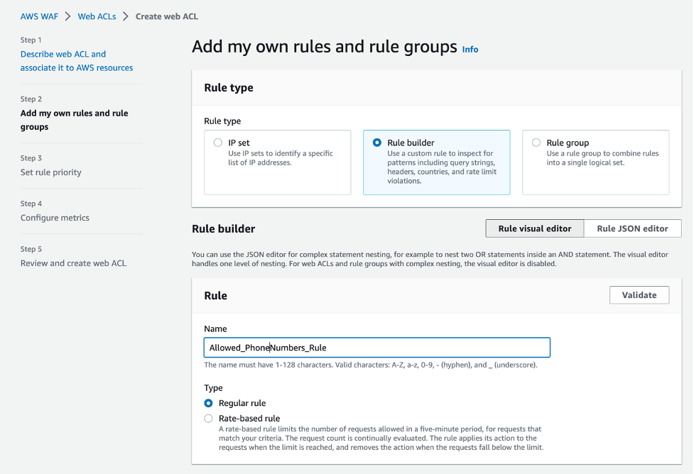
You’ll be shown a policy that grants IAM Identity Center users access to the same Amazon S3 bucket so that they can use the AWS Management Console to store their information. The policy allows users in the company to upload or download files from their department’s folder, but not to access any other department’s folder in the bucket.
After the policy is explained, you’ll see how to create an individual policy for each IAM Identity Center user.
Throughout the rest of this post, you will use a policy, which will be associated with an IAM Identity Center user named David. Also, you must have already created an S3 bucket.
Note: S3 buckets have a global namespace and you must change the bucket name to a unique name.
For this blog post, you will need an S3 bucket with the following structure (the example bucket name for the rest of the blog is “my-new-company-123456789”):
/home/Adele/
 /home/Bob/
 /home/David/
 /confidential/
 /root-file.txt
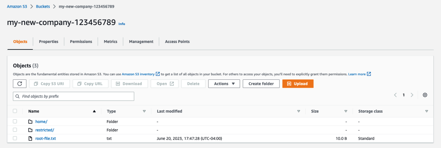
Figure 1: Screenshot of the root of the my-new-company-123456789 bucket
Your S3 bucket structure should have two folders, home and confidential, with a file root-file.txt in the main bucket directory. Inside confidential you will have no items or folders. Inside home there should be three sub-folders: Adele, Bob, and David.
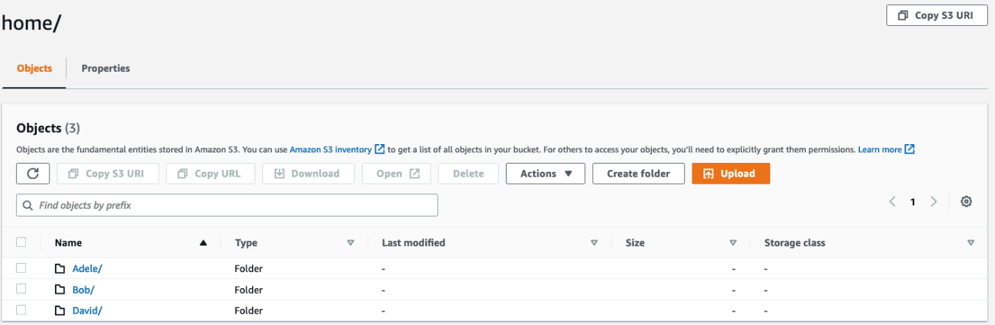
Figure 2: Screenshot of the home/ directory of the my-new-company-123456789 bucket
A brief lesson about Amazon S3 objects
Before explaining the policy, it’s important to review how Amazon S3 objects are named. This brief description isn’t comprehensive, but will help you understand how the policy works. If you already know about Amazon S3 objects and prefixes, skip ahead to Creating David in Identity Center.
Amazon S3 stores data in a flat structure; you create a bucket, and the bucket stores objects. S3 doesn’t have a hierarchy of sub-buckets or folders; however, tools like the console can emulate a folder hierarchy to present folders in a bucket by using the names of objects (also known as keys). When you create a folder in S3, S3 creates a 0-byte object with a key that references the folder name that you provided. For example, if you create a folder named photos in your bucket, the S3 console creates a 0-byte object with the key photos/. The console creates this object to support the idea of folders. The S3 console treats all objects that have a forward slash (/) character as the last (trailing) character in the key name as a folder (for example, examplekeyname/)
To give you an example, for an object that’s named home/common/shared.txt, the console will show the shared.txt file in the common folder in the home folder. The names of these folders (such as home/ or home/common/) are called prefixes, and prefixes like these are what you use to specify David’s department folder in his policy. By the way, the slash (/) in a prefix like home/ isn’t a reserved character — you could name an object (using the Amazon S3 API) with prefixes such as home:common:shared.txt or home-common-shared.txt. However, the convention is to use a slash as the delimiter, and the Amazon S3 console (but not S3 itself) treats the slash as a special character for showing objects in folders. For more information on organizing objects in the S3 console using folders, see Organizing objects in the Amazon S3 console by using folders.
Creating David in Identity Center
IAM Identity Center helps you securely create or connect your workforce identities and manage their access centrally across AWS accounts and applications. Identity Center is the recommended approach for workforce authentication and authorization on AWS for organizations of any size and type. Using Identity Center, you can create and manage user identities in AWS, or connect your existing identity source, including Microsoft Active Directory, Okta, Ping Identity, JumpCloud, Google Workspace, and Azure Active Directory (Azure AD). For further reading on IAM Identity Center, see the Identity Center getting started page.
Begin by setting up David as an IAM Identity Center user. To start, open the AWS Management Console and go to IAM Identity Center and create a user.
Note: The following steps are for Identity Center without System for Cross-domain Identity Management (SCIM) turned on, the add user option won’t be available if SCIM is turned on.
- From the left pane of the Identity Center console, select Users, and then choose Add user.

Figure 3: Screenshot of IAM Identity Center Users page.
- Enter
Davidas the Username, enter an email address that you have access to as you will need this later to confirm your user, and then enter a First name, Last name, and Display name. - Leave the rest as default and choose Add user.
- Select Users from the left navigation pane and verify you’ve created the user David.
Figure 4: Screenshot of adding users to group in Identity Center.
- Now that you’re verified the user David has been created, use the left pane to navigate to Permission sets, then choose Create permission set.
Figure 5: Screenshot of permission sets in Identity Center.
- Select Custom permission set as your Permission set type, then choose Next.
Figure 6: Screenshot of permission set types in Identity Center.


David’s policy
This is David’s complete policy, which will be associated with an IAM Identity Center federated user named David by using the console. This policy grants David full console access to only his folder (/home/David) and no one else’s. While you could grant each user access to their own bucket, keep in mind that an AWS account can have up to 100 buckets by default. By creating home folders and granting the appropriate permissions, you can instead allow thousands of users to share a single bucket.
- Now, copy and paste the preceding IAM Policy into the inline policy editor. In this case, you use the JSON editor. For information on creating policies, see Creating IAM policies.
Figure 7: Screenshot of the inline policy inside the permissions set in Identity Center.
- Give your permission set a name and a description, then leave the rest at the default settings and choose Next.
- Verify that you modify the policies to have the bucket name you created earlier.
- After your permission set has been created, navigate to AWS accounts on the left navigation pane, then select Assign users or groups.
Figure 8: Screenshot of the AWS accounts in Identity Center.
- Select the user David and choose Next.
Figure 9: Screenshot of the AWS accounts in Identity Center.
- Select the permission set you created earlier, choose Next, leave the rest at the default settings and choose Submit.
Figure 10: Screenshot of the permission sets in Identity Center.
You’ve now created and attached the permissions required for David to view his S3 bucket folder, but not to view the objects in other users’ folders. You can verify this by signing in as David through the AWS access portal.
Figure 11: Screenshot of the settings summary in Identity Center.
- Navigate to the dashboard in IAM Identity Center and go to the Settings summary, then choose the AWS access portal URL.

Figure 12: Screenshot of David signing into the console via the Identity Center dashboard URL.
- Sign in as the user David with the one-time password you received earlier when creating David.
Figure 13: Second screenshot of David signing into the console through the Identity Center dashboard URL.
- Open the Amazon S3 console.
- Search for the bucket you created earlier.
Figure 14: Screenshot of my-new-company-123456789 bucket in the AWS console.
- Navigate to David’s folder and verify that you have read and write access to the folder. If you navigate to other users’ folders, you’ll find that you don’t have access to the objects inside their folders.


David’s policy consists of four blocks; let’s look at each individually.
Block 1: Allow required Amazon S3 console permissions
Before you begin identifying the specific folders David can have access to, you must give him two permissions that are required for Amazon S3 console access: ListAllMyBuckets and GetBucketLocation.
The ListAllMyBuckets action grants David permission to list all the buckets in the AWS account, which is required for navigating to buckets in the Amazon S3 console (and as an aside, you currently can’t selectively filter out certain buckets, so users must have permission to list all buckets for console access). The console also does a GetBucketLocation call when users initially navigate to the Amazon S3 console, which is why David also requires permission for that action. Without these two actions, David will get an access denied error in the console.
Block 2: Allow listing objects in root and home folders
Although David should have access to only his home folder, he requires additional permissions so that he can navigate to his folder in the Amazon S3 console. David needs permission to list objects at the root level of the my-new-company-123456789 bucket and to the home/ folder. The following policy grants these permissions to David:
Without the ListBucket permission, David can’t navigate to his folder because he won’t have permissions to view the contents of the root and home folders. When David tries to use the console to view the contents of the my-new-company-123456789 bucket, the console will return an access denied error. Although this policy grants David permission to list all objects in the root and home folders, he won’t be able to view the contents of any files or folders except his own (you specify these permissions in the next block).
This block includes conditions, which let you limit under what conditions a request to AWS is valid. In this case, David can list objects in the my-new-company-123456789 bucket only when he requests objects without a prefix (objects at the root level) and objects with the home/ prefix (objects in the home folder). If David tries to navigate to other folders, such as confidential/, David is denied access. Additionally, David needs permissions to list prefix home/David to be able to use the search functionality of the console instead of scrolling down the list of users’ folders.
To set these root and home folder permissions, I used two conditions: s3:prefix and s3:delimiter. The s3:prefix condition specifies the folders that David has ListBucket permissions for. For example, David can list the following files and folders in the my-new-company-123456789 bucket:
/root-file.txt
 /confidential/
 /home/Adele/
 /home/Bob/
 /home/David/
But David cannot list files or subfolders in the confidential/, home/Adele, or home/Bob folders.
Although the s3:delimiter condition isn’t required for console access, it’s still a good practice to include it in case David makes requests by using the API. As previously noted, the delimiter is a character—such as a slash (/)—that identifies the folder that an object is in. The delimiter is useful when you want to list objects as if they were in a file system. For example, let’s assume the my-new-company-123456789 bucket stored thousands of objects. If David includes the delimiter in his requests, he can limit the number of returned objects to just the names of files and subfolders in the folder he specified. Without the delimiter, in addition to every file in the folder he specified, David would get a list of all files in any subfolders.
Block 3: Allow listing objects in David’s folder
In addition to the root and home folders, David requires access to all objects in the home/David/ folder and any subfolders that he might create. Here’s a policy that allows this:
In the condition above, you use a StringLike expression in combination with the asterisk (*) to represent an object in David’s folder, where the asterisk acts as a wildcard. That way, David can list files and folders in his folder (home/David/). You couldn’t include this condition in the previous block (AllowRootAndHomeListingOfCompanyBucket) because it used the StringEquals expression, which would interpret the asterisk (*) as an asterisk, not as a wildcard.
In the next section, the AllowAllS3ActionsInUserFolder block, you’ll see that the Resource element specifies my-new-company/home/David/*, which looks like the condition that I specified in this section. You might think that you can similarly use the Resource element to specify David’s folder in this block. However, the ListBucket action is a bucket-level operation, meaning the Resource element for the ListBucket action applies only to bucket names and doesn’t take folder names into account. So, to limit actions at the object level (files and folders), you must use conditions.
Block 4: Allow all Amazon S3 actions in David’s folder
Finally, you specify David’s actions (such as read, write, and delete permissions) and limit them to just his home folder, as shown in the following policy:
For the Action element, you specified s3:*, which means David has permission to do all Amazon S3 actions. In the Resource element, you specified David’s folder with an asterisk (*) (a wildcard) so that David can perform actions on the folder and inside the folder. For example, David has permission to change his folder’s storage class. David also has permission to upload files, delete files, and create subfolders in his folder (perform actions in the folder).
An easier way to manage policies with policy variables
In David’s folder-level policy you specified David’s home folder. If you wanted a similar policy for users like Bob and Adele, you’d have to create separate policies that specify their home folders. Instead of creating individual policies for each IAM Identity Center user, you can use policy variables and create a single policy that applies to multiple users (a group policy). Policy variables act as placeholders. When you make a request to a service in AWS, the placeholder is replaced by a value from the request when the policy is evaluated.
For example, you can use the previous policy and replace David’s user name with a variable that uses the requester’s user name through attributes and PrincipalTag as shown in the following policy (copy this policy to use in the procedure that follows):
- To implement this policy with variables, begin by opening the IAM Identity Center console using the main AWS admin account (ensuring you’re not signed in as David).
- Select Settings on the left-hand side, then select the Attributes for access control tab.
Figure 15: Screenshot of Settings inside Identity Center.
- Create a new attribute for access control, entering
userNameas the Key and${path:userName}as the Value, then choose Save changes. This will add a session tag to your Identity Center user and allow you to use that tag in an IAM policy.
Figure 16: Screenshot of managing attributes inside Identity Center settings.
- To edit David’s permissions, go back to the IAM Identity Center console and select Permission sets.
Figure 17: Screenshot of permission sets inside Identity Center with Davids-Permissions selected.
- Select David’s permission set that you created previously.
- Select Inline policy and then choose Edit to update David’s policy by replacing it with the modified policy that you copied at the beginning of this section, which will resolve to David’s username.
Figure 18: Screenshot of David’s policy inside his permission set inside Identity Center.


You can validate that this is set up correctly by signing in to David’s user through the Identity Center dashboard as you did before and verifying you have access to the David folder and not the Bob or Adele folder.
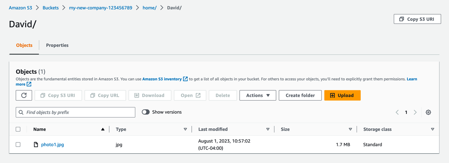
Figure 19: Screenshot of David’s S3 folder with access to a .jpg file inside.
Whenever a user makes a request to AWS, the variable is replaced by the user name of whoever made the request. For example, when David makes a request, ${aws:PrincipalTag/userName} resolves to David; when Adele makes the request, ${aws:PrincipalTag/userName} resolves to Adele.
It’s important to note that, if this is the route you use to grant access, you must control and limit who can set this username tag on an IAM principal. Anyone who can set this tag can effectively read/write to any of these bucket prefixes. It’s important that you limit access and protect the bucket prefixes and who can set the tags. For more information, see What is ABAC for AWS, and the Attribute-based access control User Guide.
Conclusion
By using Amazon S3 folders, you can follow the principle of least privilege and verify that the right users have access to what they need, and only to what they need.
See the following example policy that only allows API access to the buckets, and only allows for adding, deleting, restoring, and listing objects inside the folders:
We encourage you to think about what policies your users might need and restrict the access by only explicitly allowing what is needed.
Here are some additional resources for learning about Amazon S3 folders and about IAM policies, and be sure to get involved at the community forums:
- For a detailed walkthrough of Amazon S3 policies, see Controlling access to a bucket with user policies.
- See Listing objects using prefixes and delimiters in Organizing objects using prefixes.
- See a sample Amazon S3 API request in the Amazon S3 API Reference.
- Blocking public access to your Amazon S3 storage.
- Bucket policies and examples.
- Our previous blog post about how to grant access to an Amazon S3 bucket.
If you have feedback about this post, submit comments in the Comments section below. If you have questions about this post, contact AWS Support.
Want more AWS Security news? Follow us on Twitter.


 Rahul Sarda is a Senior Analytics & ML Specialist at AWS. He is a seasoned leader with over 20 years of experience, who is passionate about helping customers build scalable data and analytics solutions to gain timely insights and make critical business decisions. In his spare time, he enjoys spending time with his family, stay healthy, running and road cycling.
 Varun Rao Bhamidimarri is a Sr Manager, AWS Analytics Specialist Solutions Architect team. His focus is helping customers with adoption of cloud-enabled analytics solutions to meet their business requirements. Outside of work, he loves spending time with his wife and two kids, stay healthy, mediate and recently picked up gardening during the lockdown.

 Mukul Sharma is a Software Development Engineer on Data & Analytics (DnA) organization at GoDaddy. He is a polyglot programmer with experience in a wide array of technologies to rapidly deliver scalable solutions. He enjoys singing karaoke, playing various board games, and working on personal programming projects in his spare time.
 Ozcan Ilikhan is a Director of Engineering on Data & Analytics (DnA) organization at GoDaddy. He is passionate about solving customer problems and increasing efficiency using data and ML/AI. In his spare time, he loves reading, hiking, gardening, and working on DIY projects.
 Harsh Vardhan Singh Gaur is an AWS Solutions Architect, specializing in analytics. He has over 6 years of experience working in the field of big data and data science. He is passionate about helping customers adopt best practices and discover insights from their data.
 Ramesh Kumar Venkatraman is a Senior Solutions Architect at AWS who is passionate about containers and databases. He works with AWS customers to design, deploy, and manage their AWS workloads and architectures. In his spare time, he loves to play with his two kids and follows cricket.


 Mikhail Vaynshteyn is a Solutions Architect with Amazon Web Services. Mikhail works with healthcare and life sciences customers to build solutions that help improve patients’ outcomes. Mikhail specializes in data analytics services.
 Muthu Pitchaimani is a Search Specialist with Amazon OpenSearch Service. He builds large-scale search applications and solutions. Muthu is interested in the topics of networking and security, and is based out of Austin, Texas.


![Directory tree showing training dataset and model configuration structure]](https://d2908q01vomqb2.cloudfront.net/1b6453892473a467d07372d45eb05abc2031647a/2023/10/17/figure-3.jpg)


 Mykhailo Kondak is a Database Engineer in the AWS Database Migration Service team at AWS. He uses his experience with different database technologies to help Amazon customers to move their on-premises data warehouses and big data workloads to the AWS Cloud. In his spare time, he plays soccer.
 Illia Kravtsov is a Database Engineer on the AWS Database Migration Service team. He has over 10 years of experience in data warehouse development with Teradata and other massively parallel processing (MPP) databases.
 Michael Soo is a Principal Database Engineer in the AWS Database Migration Service. He builds products and services that help customers migrate their database workloads to the AWS Cloud.

 Masudur Rahaman Sayem is a Streaming Data Architect at AWS. He works with AWS customers globally to design and build data streaming architectures to solve real-world business problems. He specializes in optimizing solutions that use streaming data services and NoSQL. Sayem is very passionate about distributed computing.