Tag Archives: Best practices

Leverage L2 constructs to reduce the complexity of your AWS CDK application

Post Syndicated from David Boldt original https://aws.amazon.com/blogs/devops/leverage-l2-constructs-to-reduce-the-complexity-of-your-aws-cdk-application/

The AWS Cloud Development Kit (AWS CDK) is an open-source software development framework to define your cloud application resources using familiar programming languages. AWS CDK uses the familiarity and expressive power of programming languages for modeling your applications. Constructs are the basic building blocks of AWS CDK apps. A construct represents a “cloud component” and encapsulates everything that AWS CloudFormation needs to create the component. Furthermore, AWS Construct Library lets you ease the process of building your application using predefined templates and logic. Three levels of constructs exist:

  • L1 – These are low-level constructs called Cfn (short for CloudFormation) resources. They’re periodically generated from the AWS CloudFormation Resource Specification. The name pattern is CfnXyz, where Xyz is name of the resource. When using these constructs, you must configure all of the resource properties. This requires a full understanding of the underlying CloudFormation resource model and its corresponding attributes.
  • L2 – These represent AWS resources with a higher-level, intent-based API. They provide additional functionality with defaults, boilerplate, and glue logic that you’d be writing yourself with L1 constructs. AWS constructs offer convenient defaults and reduce the need to know all of the details about the AWS resources that they represent. This is done while providing convenience methods that make it simpler to work with the resources and as a result creating your application.
  • L3 – These constructs are called patterns. They’re designed to complete common tasks in AWS, often involving multiple types of resources.

In this post, I show a sample architecture and how the complexity of an AWS CDK application is reduced by using L2 constructs.

Overview of the sample architecture

This solution uses Amazon API Gateway, AWS Lambda, and Amazon DynamoDB. I implement a simple serverless web application. The application receives a POST request from a user via API Gateway and forwards it to a Lambda function using proxy integration. The Lambda function writes the request body to a DynamoDB table.

The sample code can be found on GitHub.

The sample code can be found on GitHub.

Walkthrough

You can follow the instructions in the README file of the GitHub repository to deploy the stack. In the following walkthrough, I explain each logical unit and the differences when implementing it using L1 and L2 constructs. Before each code sample, I’ll show the path in the GitHub repository where you can find its source.

Create the DynamoDB table

First, I create a DynamoDB table to store the request content.

L1 construct

With L1 constructs, I must define each attribute of a table separately. For the DynamoDB table, these are keySchemaattributeDefinitions, and provisionedThroughput. They all require detailed CloudFormation knowledge, for example, how a keyType is defined.

lib/level1/database/infrastructure.ts

this.cfnDynamoDbTable = new dynamodb.CfnTable(
   this, 
   "CfnDynamoDbTable", 
   {
      keySchema: [
         {
            attributeName: props.attributeName,
            keyType: "HASH",
         },
      ],
      attributeDefinitions: [
         {
            attributeName: props.attributeName,
            attributeType: "S",
         },
      ],
      provisionedThroughput: {
         readCapacityUnits: 5,
         writeCapacityUnits: 5,
      },
   },
);

L2 construct

The corresponding L2 construct lets me use the default values for readCapacity (5) and writeCapacity (5). To further reduce the complexity, I define the attributes and the partition key simultaneously. In addition, I utilize the dynamodb.AttributeType.STRING enum.

lib/level2/database/infrastructure.ts

this.dynamoDbTable = new dynamodb.Table(
   this, 
   "DynamoDbTable", 
   {
      partitionKey: {
         name: props.attributeName,
         type: dynamodb.AttributeType.STRING,
      },
   },
);

Create the Lambda function

Next, I create a Lambda function which receives the request and stores the content in the DynamoDB table. The runtime code uses Node.js.

L1 construct

When creating a Lambda function using L1 construct, I must specify all of the properties at creation time – the business logic code location, runtime, and the function handler. This includes the role for the Lambda function to assume. As a result, I must provide the Attribute Resource Name (ARN) of the role. In the “Granting permissions” sections later in this post, I show how to create this role.

lib/level1/api/infrastructure.ts

const cfnLambdaFunction = new lambda.CfnFunction(
   this, 
   "CfnLambdaFunction", 
   {
      code: {
         zipFile: fs.readFileSync(
            path.resolve(__dirname, "runtime/index.js"),
            "utf8"
         ),
      },
      role: this.cfnIamLambdaRole.attrArn,
      runtime: "nodejs16.x",
      handler: "index.handler",
      environment: {
         variables: {
            TABLE_NAME: props.dynamoDbTableArn,
         },
      },
   },
);

L2 construct

I can achieve the same result with less complexity by leveraging the NodejsFunction L2 construct for Lambda function. It sets a default version for Node.js runtime unless another one is explicitly specified. The construct creates a Lambda function with automatic transpiling and bundling of TypeScript or Javascript code. This results in smaller Lambda packages that contain only the code and dependencies needed to run the function, and it uses esbuild under the hood. The Lambda function handler code is located in the runtime directory of the API logical unit. I provide the path to the Lambda handler file in the entry property. I don’t have to specify the handler function name, because the NodejsFunction construct uses the handler name by default. Moreover, a Lambda execution role isn’t required to be provided during L2 Lambda construct creation. If no role is specified, then a default one is generated which has permissions for Lambda execution. In the section ‘Granting Permissions’, I describe how to customize the role after creating the construct.

lib/level2/api/infrastructure.ts

this.lambdaFunction = new lambda_nodejs.NodejsFunction(
   this, 
   "LambdaFunction", 
   {
      entry: path.resolve(__dirname, "runtime/index.ts"),
      runtime: lambda.Runtime.NODEJS_16_X,
      environment: {
         TABLE_NAME: props.dynamoDbTableName,
      },
   },
);

Create API Gateway REST API

Next, I define the API Gateway REST API to receive POST requests with Cross-origin resource sharing (CORS) enabled.

L1 construct

Every step, from creating a new API Gateway REST API, to the deployment process, must be configured individually. With an L1 construct, I must have a good understanding of CORS and the exact configuration of headers and methods.

Furthermore, I must know all of the specifics, such as for the Lambda integration type I must know how to construct the URI.

lib/level1/api/infrastructure.ts

const cfnApiGatewayRestApi = new apigateway.CfnRestApi(
   this, 
   "CfnApiGatewayRestApi", 
   {
      name: props.apiName,
   },
);

const cfnApiGatewayPostMethod = new apigateway.CfnMethod(
   this, 
   "CfnApiGatewayPostMethod", 
   {
      httpMethod: "POST",
      resourceId: cfnApiGatewayRestApi.attrRootResourceId,
      restApiId: cfnApiGatewayRestApi.ref,
      authorizationType: "NONE",
      integration: {
         credentials: cfnIamApiGatewayRole.attrArn,
         type: "AWS_PROXY",
         integrationHttpMethod: "ANY",
         uri:
            "arn:aws:apigateway:" +
            Stack.of(this).region +
            ":lambda:path/2015-03-31/functions/" +
            cfnLambdaFunction.attrArn +
            "/invocations",
            passthroughBehavior: "WHEN_NO_MATCH",
      },
   },
);

const CfnApiGatewayOptionsMethod = new apigateway.CfnMethod(
    this,
    "CfnApiGatewayOptionsMethod",
   {    
      // fields omitted
   },
);

const cfnApiGatewayDeployment = new apigateway.CfnDeployment(
    this,
    "cfnApiGatewayDeployment",
    {
      restApiId: cfnApiGatewayRestApi.ref,
      stageName: "prod",
    },
);

L2 construct

Creating an API Gateway REST API with CORS enabled is simpler with L2 constructs. I can leverage the defaultCorsPreflightOptions property and the construct builds the required options method. To set origins and methods, I can use the apigateway.Cors enum. To configure the Lambda proxy option, all I need to do is to set the proxy variable in the method to true. A default deployment is created automatically.

lib/level2/api/infrastructure.ts

this.api = new apigateway.RestApi(
   this, 
   "ApiGatewayRestApi", 
   {
      defaultCorsPreflightOptions: {
         allowOrigins: apigateway.Cors.ALL_ORIGINS,
         allowMethods: apigateway.Cors.ALL_METHODS,
      },
   },
);

this.api.root.addMethod(
    "POST",
    new apigateway.LambdaIntegration(this.lambdaFunction, {
      proxy: true,
    })
);

Granting permissions

In the sample application, I must give permissions to two different resources:

  1.  API Gateway REST API to invoke the Lambda function.
  2. Lambda function to write data to the DynamoDB table.

L1 construct

For both resources, I must define AWS Identity and Access Management (IAM) roles. This requires in-depth knowledge of IAM, how policies are structured, and which actions are required. In the following code snippet, I start by creating the policy documents. Afterward, I create a role for each resource. These are provided at creation time to the corresponding constructs as shown earlier.

lib/level1/api/infrastructure.ts

const cfnLambdaAssumeIamPolicyDocument = {
    // fields omitted
};

this.cfnLambdaIamRole = new iam.CfnRole(
   this, 
   "cfnLambdaIamRole", 
   {
      assumeRolePolicyDocument: cfnLambdaAssumeIamPolicyDocument,
      managedPolicyArns: [
        "arn:aws:iam::aws:policy/service-role/AWSLambdaBasicExecutionRole",
      ],
   },
);
    
const cfnApiGatewayAssumeIamPolicyDocument = {
   // fields omitted
};

const cfnApiGatewayInvokeLambdaIamPolicyDocument = {
   Version: "2012-10-17",
   Statement: [
      {
         Action: ["lambda:InvokeFunction"],
         Resource: [cfnLambdaFunction.attrArn],
         Effect: "Allow",
      },
   ],
};

const cfnApiGatewayIamRole = new iam.CfnRole(
   this, 
   "cfnApiGatewayIamRole", 
   {
      assumeRolePolicyDocument: cfnApiGatewayAssumeIamPolicyDocument,
      policies: [{
         policyDocument: cfnApiGatewayInvokeLambdaIamPolicyDocument,
         policyName: "ApiGatewayInvokeLambdaIamPolicy",
      }],
   },
);

The database construct exposes a function to grant write access to any IAM role. The function creates a policy, which allows dynamodb:PutItem on the database table and adds it as an additional policy to the role.

lib/level1/database/infrastructure.ts

grantWriteData(cfnIamRole: iam.CfnRole) {
   const cfnPutDynamoDbIamPolicyDocument = {
      Version: "2012-10-17",
      Statement: [
         {
            Action: ["dynamodb:PutItem"],
            Resource: [this.cfnDynamoDbTable.attrArn],
            Effect: "Allow",
         },
      ],
   };

    cfnIamRole.policies = [{
        policyDocument: cfnPutDynamoDbIamPolicyDocument,
        policyName: "PutDynamoDbIamPolicy",
    }];
}

At this point, all permissions are in place, except that Lambda function doesn’t have permissions to write data to the DynamoDB table yet. To grant write access, I call the grantWriteData function of the Database construct with the IAM role of the Lambda function.

lib/deployment.ts

database.grantWriteData(api.cfnLambdaIamRole)

L2 construct

Creating an API Gateway REST API with the LambdaIntegration construct generates the IAM role and attaches the role to the API Gateway REST API method. Giving the Lambda function permission to write to the DynamoDB table can be achieved with the following single line:

lib/deployment.ts

database.dynamoDbTable.grantWriteData(api.lambdaFunction);

Using L3 constructs

To reduce complexity even further, I can leverage L3 constructs. In the case of this sample architecture, I can utilize the LambdaRestApi construct. This construct uses a default Lambda proxy integration. It automatically generates a method and a deployment, and grants permissions. As a result, I can achieve the same with even less code.

const restApi = new apigateway.LambdaRestApi(
   this, 
   "restApiLevel3", 
   {
      handler: this.lambdaFunction,
      defaultCorsPreflightOptions: {
         allowOrigins: apigateway.Cors.ALL_ORIGINS,
         allowMethods: apigateway.Cors.ALL_METHODS
      },
   },
);

Cleanup

Many services in this post are available in the AWS Free Tier. However, using this solution may incur costs, and you should tear down the stack if you don’t need it anymore. Cleanup steps are included in the RADME file of the GitHub repository.

Conclusion

In this post, I highlight the difference between using L1 and L2 AWS CDK constructs with an example architecture. Leveraging L2 constructs reduces the complexity of your application by using predefined patterns, boiler plate, and glue logic. They offer convenient defaults and reduce the need to know all of the details about the AWS resources they represent, while providing convenient methods that make it simpler to work with the resource. Additionally, I showed how to reduce complexity for common tasks even further by using an L3 construct.

Visit the AWS CDK documentation to learn more about building resilient, scalable, and cost-efficient architectures with the expressive power of a programming language.

Author:

David Boldt

David Boldt is a Solutions Architect at AWS, based in Hamburg, Germany. David works with customers to enable them with best practices in their cloud journey. He is passionate about the internet of Things and how it can be leveraged to solve different challenges across industries.

Selecting Network Switches for Your AWS Outposts

Post Syndicated from Sheila Busser original https://aws.amazon.com/blogs/compute/selecting-network-switches-for-your-aws-outposts/

This blog post is written by, Frankie Negro, Outposts Solution Architect.

AWS Outposts is a family of fully managed solutions that extend AWS infrastructure, services, APIs, and tools to customer premises. Outposts is available in a variety of form factors, from 1U and 2U Outposts servers (https://aws.amazon.com/outposts/servers/) to 42U Outposts racks (https://aws.amazon.com/outposts/rack/). AWS Outposts is ideal for workloads that require low-latency access to on-premises systems, local data processing, data residency, and application migration with local system interdependencies.

When operating and consuming services in the AWS Regions, the underlying networking layer is completely abstracted. You do not need to be aware of the underlying networking topology, device port speeds, connectors, transports, links, and media types. Instead, the focus is on design, with the architecture leveraging the high-level constructs available for the Amazon Virtual Private Cloud (VPC), such as VPCs, Subnets, Route Tables, Security Groups, and network access control lists. The network bandwidth available for an Amazon Elastic Compute Cloud (Amazon EC2) instance depends on the number of vCPUs that it has.

AWS Outposts requires a dedicated network connection to an AWS Region defined by the customer when ordering the product. This connection is called the Service Link, and it connects to either public or private anchors (not both) in a specific Availability Zone (AZ) in the selected parent Region. AWS recommends redundant connections that meet the bandwidth requirements for Outposts rack and Outposts servers.

The purpose of AWS Outposts is to fulfill use cases where the workload has requirements that prevent or make it unfeasible to operate in the AWS Regions. Most of these use cases, such as low latency and local data processing, require strong and reliable network infrastructure to handle a high volume of packets per second.

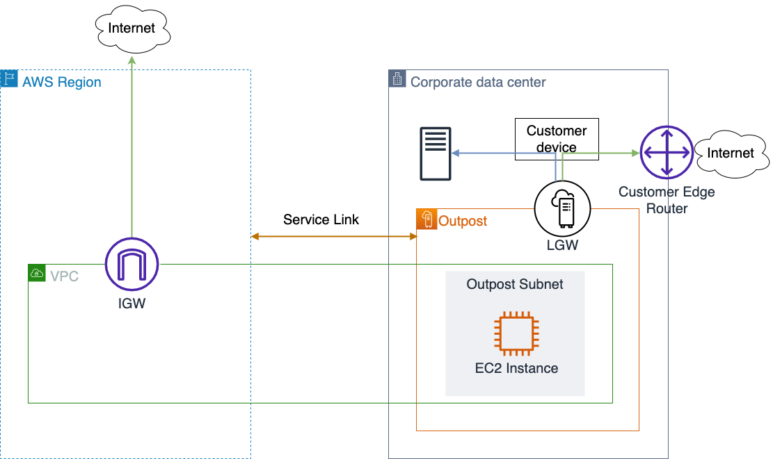
The construct connecting AWS Outposts to the customer on-premises network is called local gateway (LGW) for Outposts rack and local network interface (LNI) for Outposts Servers. These logical elements mediate the data traffic between Outposts and the customer premises.

On Outposts rack, Service Link and LGW traffic flows through the same network connection, which can be a single link per physical device or an aggregated link. Network packets sent to the Region or to your local network are segregated using distinct virtual LANs (VLANs) on Outposts rack. The smaller family members, Outposts servers, use two distinct physical ports.

The physical network elements providing the connections between the devices and services are called Outposts Networking Devices (ONDs) on the AWS side and Customer Networking Devices (CNDs) on the customer side. For its part, Outposts rack can deliver throughput up to 400 Gbps, aggregating 4 x 100 Gbps uplinks to support Service Link and LGW network traffic, while an Outposts server can provide a 10 Gbps dedicated network port for each traffic.

Outpost network traffic segments and logical elements

The upstream devices you provide play a fundamental role in the harmonic coexistence and operation at the ethernet physical and data link layers, which are the basis for performance and stability of the upper network and transport layers as defined by the OSI model. A careful selection of your upstream networking devices must combine reliable operations, cost effectiveness, and long-term vision.

The physical layer (L1)

Here we are talking about physical cables and media interfaces. There are no supported options for UTP Cables with RJ-45 connectors, as Outposts rack only supports Fiber Optic cables with Lucent Connectors (LC). For short distances you can use MMF (Multi-Mode Fiber) or MMF OM4 (Optical Multimode) with LC.  Longer distances can be achieved using SMF (Single Mode Fiber). Distance limits depend on the Fiber Mode and Type.

: Lucent Connector (LC) DuplexEach Outposts server has one physical QSFP+ interface. A 4-way breakout cable is supplied with SFP+ transceivers. You will use two interfaces: One for the LNI traffic and another for the Service Link traffic.

With this is mind, RJ-45 ports on upstream switches will not suit any AWS Outposts connections. Switch models that combine RF-45 and optical ports can be used in conjunction with copper ethernet cables category 8 (CAT8), which support up to 40 Gbps speeds, to connect other segments while the optical ports can be used for AWS Outposts.

When evaluating your upstream switches, bear in mind that Outposts rack switches are always capable of 1 / 10 / 40 / 100 Gbps speeds, and it is the same equipment regardless of the selected AWS Outposts resource ID and uplink connection speed defined during the order process.

It is recommended to account for future traffic needs from the beginning and specify upstream switches with 40 or 100 Gbps ports rather than start small and upgrade in the future. Upgrades and changes always carry risk, so limiting future risk by minimizing the need for upgrades will help mitigate issues and provide a stable, productive environment.

Another characteristic to look for when selecting your networking devices is “non-blocking” switches. These switches can handle all ports at full capacity simultaneously, without contention. It is a simple feature to select, and you can expect high performance out-of-the box without having to go too deep into details such as buffering mechanisms.

The Data Link layer (L2)

This layer establishes and terminates the logical links between nodes and exchange frames end-to-end. Outposts rack requires that your upstream devices support 802.1Q (Dot1q) standards that implement the VLAN support needed to segregate traffic to be forwarded to the Region (via Service Link) from traffic to be forwarded to the customer’s local network.

Most core switches ship with this capability. One good spec to evaluate is the maximum size of the MAC Address Table per VLAN supported by the switch. If the MAC Table gets full, your equipment may fail over to broadcast mode in that VLAN, which introduces additional stress in the network and is a potential exploit condition.

Another common feature for core switches is to support link aggregation or bundle links together so they act like a single, logical link. While AWS Outposts will work with just a single connection per OND, a recommended fault tolerance and high availability best practice is to aggregate multiple paths to withstand the failure of one or multiple members of the logical aggregation group.

As defined in the AWS Well-Architected Framework Reliability pillar design principles, to observe best practices of Automatically recover from failure and Scale horizontally to increase aggregate workload availability, you should consider implementing, for example, 4 x 10 Gbps instead of a single 40 Gbps uplink. AWS Outposts uses link aggregation control protocol (LACP) aggregations with the immediate customer network device (CND) according to the IEEE 802.3ad standard.

To learn more about how you can architect Outposts for network failures, check out the AWS Outposts High Availability Design and Architecture Considerations at this URL.

The logical interface defined as a result of the link aggregation (LAG) can be configured as an ethernet trunk port defined in the IEEE 802.1q standard to allow the use of multiple VLANs. Alternatively, the logical interface can be configured as an L3 interface with the Service Link and LGW defined as VLAN sub-interfaces. This is how AWS Outposts segregates traffic forwarded to Service Link from packets sent to the customer local network.

The Network layer (L3)

At this layer, we get into routing and logical addressing. Outposts rack requires Border Gateway Protocol (BGP) to dynamically exchange routes. Each OND device will establish eBGP peering with the upstream routing device for the Service Link and the LGW.

The architectural decision will be a trade-off between discrete components for routing and switching and an L3 switch capable of BGP routing. This aspect requires a careful assessment. It is common for a core switch to offer L3 capabilities, but BGP support is not available in most cases.

Switch design often aims for excelling at L2 and basic L3. If the network design requires advanced routing features or large IP routing tables, the safest path is to specify a powerful L2 switch and a dedicated L3 router.

Redundant equipment for fault tolerance is recommended as well. AWS does not have restrictions on how the customer implements core switches, but it’s always a good practice to keep it simple and standard, avoiding designs that include proprietary solutions, such as Virtual Chassis and Switch Clustering, because it can make troubleshooting difficult.

Conclusion

In this post, I showed the importance of dedicating time and effort to carefully evaluating the networking landscape where your AWS Outposts will be deployed, assessing the network device options available to you, designing for high-availability, and selecting switch models with proper feature sets and future-proof specifications.

The performance and operation of your AWS Outposts is largely dependent on your network substrate, and all efforts dedicated to making good decisions will be time well spent, allowing you to get the best value out of your hybrid solution while focusing on creating compelling applications and addressing your use cases with AWS Outposts.

Tighten your package security with CodeArtifact Package Origin Control toolkit

Post Syndicated from Davide Semenzin original https://aws.amazon.com/blogs/devops/tighten-your-package-security-with-codeartifact-package-origin-control-toolkit/

Introduction

AWS CodeArtifact is a fully managed artifact repository service that makes it easy for organizations to securely store and share software packages used for application development. On Jul14 2022 we introduced a new feature called Package Origin Controls which allows customers to protect themselves against “dependency substitution“ or “dependency confusion” attacks.

This class of supply chain attacks can be carried out when an attacker with knowledge of an organization’s internally published package names (for example: Sample-Package=1.0.0) is able to publish such name(s) in a public repository. Package managers contain dependency resolution logic that pulls the latest version of a package. The attacker abuses this logic by publishing a high version number of a package with the same name as the organization’s package (for example: Sample-Package=99.0.0). The package manager then would resolve any requests for that package by pulling the attacker’s package version with malicious code instead of the internally published dependency.

In order for this type of attack to be successful, the organization must source their package versions from both internal and remote repositories at the same time. For example, your pip installation could be configured with multiple package indexes, both internal and external; or, as a CodeArtifact user you may have both the repository containing your private packages as well as an external connection to PyPI in the upstream graph of your current repository. In either case, the package manager is able to obtain package versions from more than one source. This causes the package manager to resolve the higher version number from the remote repository, instead of the trusted internal version.

A few strategies can be used to mitigate this kind of mixing: a simple one is to instruct the package manager to only source from an internal repository. While effective, this is often not practical, because it either significantly degrades developer experience or requires a lot of effort in order to set up, maintain, and vet external dependencies. Another mitigation consists in using explicit version pinning, which is also effective, though it might re-introduce the dependency substitution risk upon dependency upgrade without manual vetting. Some package managers also support namespaces or other types of dependency scoping, which are also helpful in preventing this class of attacks, but when available may not always actionable for existing packages due to the large amount of work required to do the renaming.

CodeArtifact is adding another tool to strengthen your software supply chain by introducing per-package per-repository controls which allow you to more precisely configure and control how package versions are sourced. For each package in your repository, you are now able to decide whether to allow or block sourcing versions from both upstream sources and direct publishing. These flags enable you to prevent mixed versions scenarios for all the types of packages supported by CodeArtifact without the need for additional package manager configuration.

While packages retained or published after the launch of this feature come with tighter-by-default origin configurations, in keeping with the principle of least astonishment we decided not to apply any of these policies retroactively. Therefore, your existing packages in CodeArtifact will not have their origin configuration changed and your setup will continue to work continue to work as it did before the feature was released.

Should you want to leverage this feature to tighten the security posture of your existing packages, we are releasing a toolkit to make it easier to bulk-set policy values in your repositories. This blog post describes how to use it.

Solution overview

The purpose of the Package Origin Control toolkit is to provide repository administrators with an easy way to set Origin Control policies in bulk on packages that have not received the default protection because they pre-date feature release. This can be achieved by blocking upstream versions for internal packages. In this blog post we will focus on this use-case, though the toolkit does support blocking publishing package versions to avoid a potentially vulnerable mixed state for external packages as well.

The toolkit is comprised of two scripts: a first one called generate_package_configurations.py for creating a manifest file listing the packages in a domain alongside their proposed origin configuration to apply, and a second one named apply_package_configurations.py, that reads the manifest file and applies the configuration within.

generate_package_configurations.py can operate on a whole repository, or on a subset of packages (specified either via filters, or though a list) and supports two origin control resolution modes:

  • A manual one where you supply the origin configuration you would like to set for all packages in scope. This is a good option if, for instance, you already maintain a list of internal packages, or if they are published in a consistent internal namespace which allows for them to be easily selected.
  • An automated one, which tries to identify what packages should have their upstreams blocked by analyzing the upstream repository graph and external connections, looking for evidence that package versions are only available from the repository at hand- in which case it determines it can disable sourcing of upstream versions can be done without risk of breaking builds. This is a good option if you want a quick way to tighten your security posture without having to manually analyze your whole repository.

With the manifest created, apply_package_configurations.py takes it as an input and effects the changes specified in it by calling the new PutPackageOriginConfiguration API (link). Precisely because it is meant to set these values in bulk, this script supports backup and revert operations by default, as well as dry-run and step-by-step confirmation options. If you identify an issue after applying origin control changes, you will be able to safely revert to the original, working configuration before trying again.

In this blog post we will cover how to use these tools:

  • To block package versions from upstream sources for all recommended packages in a repository
  • To block upstreams for a list of packages you already have
  • To revert to the original state in case of an incorrect configuration push

Prerequisites

The following prerequisites are required before you begin:

  1. Set up the Package Origin Control toolkit as described in the README on GitHub. You will need a working installation of Python 3.6 or later as well as the ability to install dependencies like the Python AWS SDK. The AWS CLI is not required.
  2. Write permissions on the CodeArtifact repository where you want to add package origin controls (see this link for additional info.)

Procedures

To block package versions from upstream sources for all recommended packages in a repository

Introduction

This procedure should be considered if you have a CodeArtifact repository with a variety of package formats and upstreams, and you want to have the toolkit automatically resolve what packages are safe to block upstreams for. It will block acquisition of new versions from upstreams only if two conditions are met:

  • the target repository doesn’t have access to an external connection
  • no versions of the package are available via any of its upstream repositories (either because the target repository itself doesn’t have any upstreams or because none of the upstreams have the package).

Therefore, we assume there isn’t an immediate External Connection attached to the target repository for the package format(s) you are trying to run this script against (because in that case the script would fall back on leaving things as-is for all packages).

Steps

  1. Make sure you have completed the required prerequisites described above
  2. Identify the target repository in your domain you want to automatically apply origin controls for, e.g. myrepo
  3. Identify the query parameters that define the list of packages you want to target. The script supports the same filters as the ListPackagesAPI.
    1. To match all packages in a repo, run :  python generate_package_configurations.py --region us-west-2 --domain mydomain --repository myrepo
      Please note that you always need to specify the AWS region and CodeArtifact domain alongside the repository.
    2. To match only some packages in a repo, for example only Python packages whose name begins with “internal_software_”:  python generate_package_configurations.py --region us-west-2 --domain mydomain --repository myrepo --format pypi --prefix internal_software_*
  4. If necessary, you can review the produced manifest file, which you will be able to find in the same folder under the name origin-configuration_mydomain_myrepo.csv (unless you have specified a different filename and path via the --output-file option)
  5. If the manifest file looks correct, you can apply the changes by calling the second stage: python apply_package_configurations.py --region us-west-2 --domain mydomain --repository myrepo --input origin-configuration_mydomain_myrepo.csv

To block package versions from upstream sources for all packages in a repository matching a list you maintain

Introduction

This procedure should be considered if you have a set of packages within your repository you know you want to apply origin control restrictions to. Rather than relying on a query, you can use such a list as an input to create a manifest.

Steps

Create a file containing a list of package names (and package names only). Multiple namespaces and formats are not supported and you will need to re-run this procedure for each. The expected file format is one package name per line. In this example we will want to block upstreams for three packages of the npm format (format is always mandatory when specifying a list of packages). As an example, a small input file is going to look something like this:

requests
numpy
django

(more information about this option can be found in the README)

Generate the manifest by supplying this file to the first stage, alongside the desired origin control configuration. In this case, we want to block upstreams for all packages in the supplied list (for more information about the origin control configuration string, consult the documentation): python generate_package_configurations.py --region us-west-2 --domain mydomain --repository myrepo --format npm --from-list inputfile.csv --set-restrictions publish=ALLOW,upstream=BLOCK

If necessary, you can review the produced manifest file, which you will be able to find in the same folder under the name origin-configuration_mydomain_myrepo.csv (unless you have specified a different filename and path via the –output-file option)

Run the apply_package_configurations.py script to update the package origin controls in your repository: apply_package_configurations.py --region us-west-2 --domain mydomain --repository myrepo --input origin-configuration_mydomain_myrepo.csv

To revert to the original state in case of an incorrect configuration push

Introduction

Erroneously bulk-changing your origin configuration can lead to broken builds and confusing failure modes for developers. To mitigate this risk, the toolkit backs up the existing configuration before making any changes and lets you easily revert them if need be.

Steps

Identify the manifest containing the configuration you want to revert. The toolkit automatically creates a backup file t for every input manifest you provide. This is the file produced by the first stage, which by default takes a name like origin-configuration_[domain]_[repository], for example origin-configuration_mydomain_myrepo.csv
Run the second stage script in restore mode:  python apply_package_configurations.py --region us-west-2 --domain mydomain --repository myrepo --input origin-configuration_mydomain_myrepo.csv --restore

Conclusion

In this blog post we have explained how to use the Origin Control toolkit to improve package security, focusing on restricting upstream package versions. We have demonstrated both an automated repository-wide application of the toolkit, which tries to minimize the amount of repository administrator work by applying a restriction heuristic, as well as a manual mode where a repository administrator can effect fine-grained origin control changes. Finally, we showed how these changes can be reverted using the built-in backup feature.

Author:

Davide Semenzin

Davide is a Software Development Engineer on the CodeArtifact team at Amazon Web Services (AWS). Previously he has worked at the Internet Archive building the infrastructure to digitize a million books per year. His interests are distributed systems, platform engineering and mission-critical high availability software. In his free time he likes to read books, fly airplanes, fly on airplanes, think about rockets and play with lasers.

Automating Amazon EC2-Windows EBS Volumes monitoring and creating alarms

Post Syndicated from Sheila Busser original https://aws.amazon.com/blogs/compute/automating-amazon-ec2-windows-ebs-volumes-monitoring-and-creating-alarms/

This blog post is written by, Santhosh Kumar Adapa, Database Consultant,  AWS WWCO ProServe,  Jeevan Shetty, Database Consultant, AWS WWCO ProServe, and Bhanu Ganesh Gudivada, Consultant  Databases, AWS WWCO ProServe.

Customers who are running fleets of Amazon Elastic Compute Cloud (Amazon EC2) instances use advanced monitoring techniques to observe their operational performance. Capabilities like aggregated and custom dimensions help customers categorize and customize their metrics across server fleets for fast and efficient decision making. Customers require visibility into not only infrastructure metrics (such as CPU and memory), but also disk usage metrics.

Monitoring Amazon EC2-Windows Amazon Elastic Block Store (Amazon EBS) Volumes usage is critical, especially when customers have a large fleet of Amazon EC2 Windows servers running to host their databases and applications in AWS. Generally, we see issues with EC2 instances running out of disk space, and free disk space isn’t a metric that is directly available with Amazon CloudWatch. Amazon CloudWatch agent helps solve this problem. After installing and configuring the CloudWatch agent on your EC2 instance, the agent will send metric data with the disk utilization to CloudWatch. The next step is to create a CloudWatch alarm to monitor the disk utilization metric.

In this post, we showcase the steps to automate the monitoring and creating alarms for EBS volumes attached to Amazon EC2 Windows instances. Alarms are created using AWS Lambda that monitors the free disk space and alerts whenever thresholds are crossed using Amazon Simple Notification Service (Amazon SNS).

Solution overview

To demonstrate the solution we first install and configure the CloudWatch agent in your Amazon EC2 Windows instance, and then the agent will send metric data with the disk utilization to CloudWatch. To monitor the disk on each Amazon EC2 Windows instance, we’ll use two custom Metrics, “FreeStorageSpaceInMB” and “FreeStorageSpaceInPercent”, that are collected by CloudWatch agent and pushed to CloudWatch.

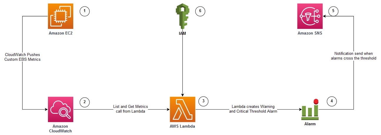
The following diagram illustrates the architecture used in this post:

architecture used in this post

  1. Amazon EC2 Windows instance with attached Amazon EBS Volumes to be monitored for free disk usage. The EC2 instance is configured with Amazon CloudWatch Agent.
  2. CloudWatch agent is configured to monitor the “FreeStorageSpaceInMB” and “FreeStorageSpaceInPercent” metrics, and pushed to AWS CloudWatch.
  3. Lambda function that can be invoked to create CloudWatch alarms for each disk attached to the EC2 instance.
  4. CloudWatch Alarms are created with warnings and critical thresholds based on storage size.
  5. Amazon SNS is used to send alerts when the CloudWatch Alarms crosses the threshold.
  6. AWS Identity and Access Management (IAM) to provide permission to the Lambda function to get Amazon EBS metrics and to create CloudWatch Alarms.

Prerequisites

You will need the following prerequisites:

  • To implement this solution, you must have an Amazon EC2 Windows instance configured with Amazon CloudWatch Agent by following the steps documented in the article – How to monitor Windows and Linux servers and get internal performance metrics.
  • To monitor the “FreeStorageSpaceInMB” and “FreeStorageSpaceInPercent” metrics for Amazon EBS volumes attached to the EC2 instance, the CloudWatch agent configuration JSON should have the following section:
"LogicalDisk": {
	"measurement": [
	{
		"name":"% Free Space",
		"rename":"FreeStorageSpaceInPercent",
		"unit":"Percent"
	},
	{
		"name":"Free Megabytes",
		"rename":"FreeStorageSpaceInMB",
		"unit":"Megabytes"
	}
	],
	"metrics_collection_interval": 10,
	"resources": [
		"*"
	]
},
  1. Amazon EC2 host or bastion host with an IAM role attached that has permissions to create an IAM role, Lambda function, and run Amazon Relational Database Service (Amazon RDS) CLI commands. A Lambda function and an IAM role are created using AWS Serverless Application Model (SAM).

AWS SAM

In this section, we provide the steps to create an IAM role and deploy a Lambda function using AWS SAM.

  1. Log in to the Amazon EC2 host and install the AWS SAM CLI.
  2. Download the source code and deploy it by running the following command:
git clone https://github.com/aws-samples/aws-ec2-windows-ebs-volumes-monitoring

cd aws-ec2-windows-ebs-volumes-monitoring/ebs_volumes_monitoring
sam deploy --guided

3. Provide the following parameters:

    1. Stack Name – Name for the AWS CloudFormation stack.
    2. AWS Region – AWS Region where the stack is being deployed.

The following is the sample output when you run sam deploy –guided with default arguments:

=========================================
Stack Name [ebs-volumes-monitoring]: ebs-volumes-monitoring
AWS Region [us-west-2]:
#Shows you resources changes to be deployed and require a 'Y' to initiate deploy
Confirm changes before deploy [y/N]:
#SAM needs permission to be able to create roles to connect to the resources in your template
Allow SAM CLI IAM role creation [Y/n]:
#Preserves the state of previously provisioned resources when an operation fails
Disable rollback [y/N]:
Save arguments to configuration file [Y/n]:
SAM configuration file [samconfig.toml]:
SAM configuration environment [default]:

In the following sections, we describe the AWS services deployed with AWS SAM.

IAM role

AWS SAM creates an IAM role with policies to describe EC2 instances, as well as List, Get, and Put CloudWatch metrics. Furthermore, it attaches an AWS managed IAM policy called AWSLambdaBasicExecutionRole to the IAM role. This role is attached to the Lambda functions to create Amazon EBS volume alarms for EC2 instances.

Lambda function

AWS SAM also deploys the Lambda function. It uses Python 3.8 and accepts two parameters:

  1. Hostname: Amazon EC2 Windows instance name, or, if we must configure alarms for multiple servers, then you can use a wild card character, such as Instance_name* or Instance_name?
  2. sns_topic_name: ARN of the SNS topic that is used to configure CloudWatch Alarms. Notification is sent to the SNS topic when the Amazon EBS Volume metric crosses the threshold.

Invoking Lambda function

After the SAM deployment is successful, we can invoke the Lambda function with the instance name and the SNS Topic ARN. The Lambda function creates two alarms (Warning and Critical) for every Amazon EBS volume attached to the instance. The Warning and Critical values can be changed in the Lambda code so that there are two different values depending on the size of the disk drive. Furthermore, the alarms are configured to send notifications to the SNS Topic. The following is the sample command to invoke the Lambda function:

aws lambda invoke --function-name ec2-ebs-metric --cli-binary-format raw-in-base64-out \
--payload '{"hostname": "Windows*", "sns_topic_name": "arn:aws:sns:us-west-2:123456789:notify_dba" }' response.json

Verifying CloudWatch Alarms:

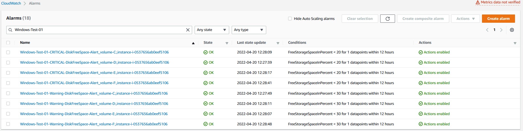
Verify the CloudWatch Alarms that are created in the CloudWatch console. The following screenshot shows the CloudWatch alarms created for an EC2 instance with four disks. There are two alarms (Warning and Critical) created for every disk (four disks in total). Therefore, we see eight CloudWatch alarms.

CloudWatch console alarms

Checking CloudWatch Logs:

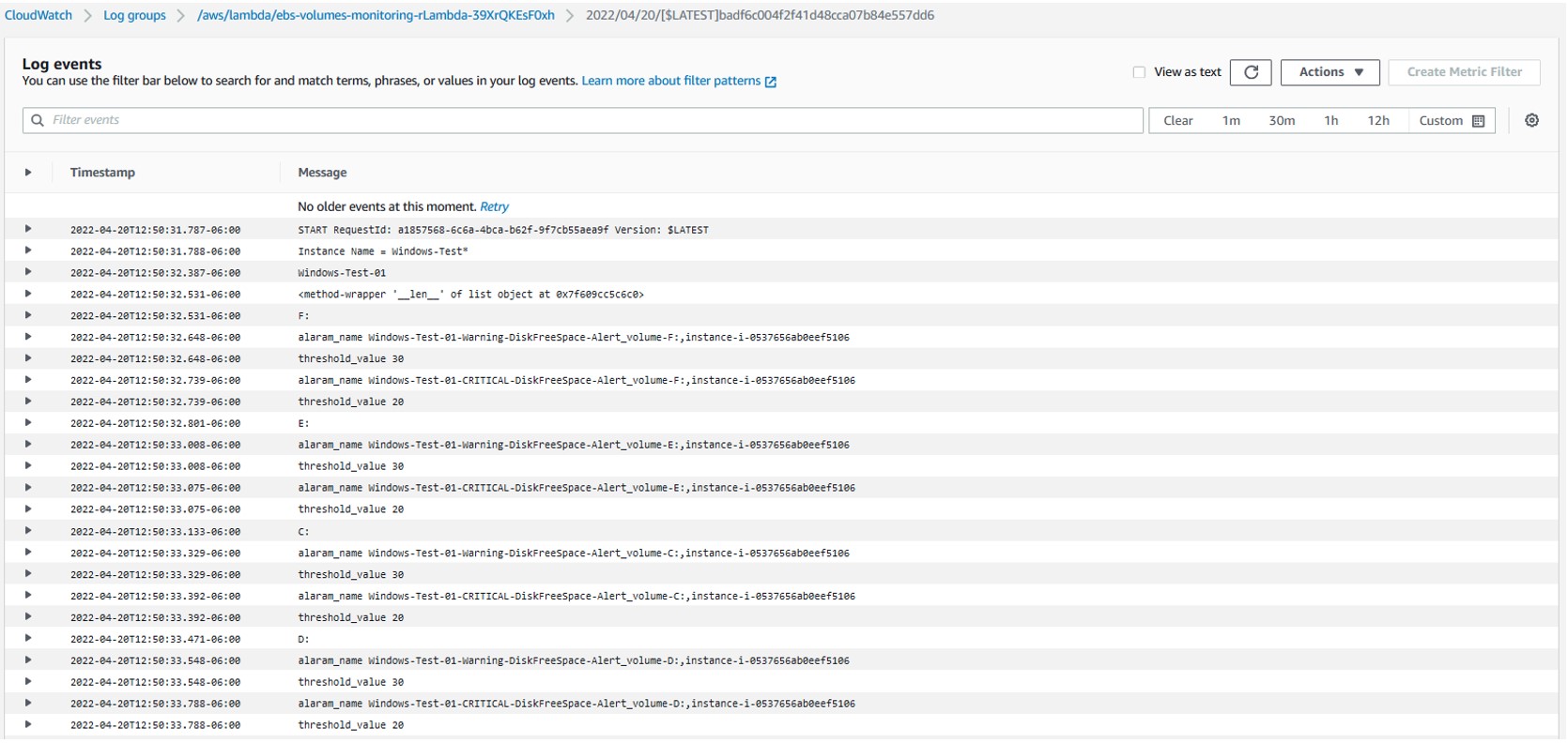
After running the Lambda function, to verify the log, go to Lambda Service page, select the Lambda function created, navigate to the Monitor tab, and then select “View logs in CloudWatch”. Then, go to the latest log file to check the CloudWatch log files for any errors.

Checking CloudWatch LogsSelect the latest Log Steam to check the details of the last Lambda function execution.

Log Steam detailsThe log file shows the full details of the Lambda function execution. Furthermore, it shows the CloudWatch alarms configured for each disk, as well as if there are any errors generated during execution.

Log file detailsCleanup

To clean up the resources used in this post, complete the following steps:

  1. Delete the CloudFormation stack by running below command and replacing STACK_NAME with stack name provided in step 3a above, under section “AWS SAM”
sam delete --stack-name STACK_NAME
  1. Confirm the stack has been deleted by running below command. Replace STACK_NAME as mentioned in previous step.
aws cloudformation list-stacks --query "StackSummaries[?contains(StackName,' STACK_NAME ')].StackStatus"
  1. Delete any CloudWatch alarms created by the Lambda function by following the document – Editing or deleting a CloudWatch alarm.

Conclusion

In this post, we demonstrated how the requirement of monitoring Amazon EC2 Windows EBS Volumes usage is critical. In particular, this is essential when customers have a large fleet of Amazon EC2 Windows servers running to host their databases and applications in the cloud. We showcased the process of automating the free disk monitoring using Lambda and notifying through Amazon SNS when disks cross the storage threshold. By implementing such monitoring, customers can prevent issues with EC2 instances running out of disk space thus preventing critical production outages.

Provide any thoughts or questions in the comments section. We also encourage you to explore CloudWatch monitoring and try out additional use cases mentioned in the documentation.

How to Mitigate Docker Hub’s pull rate limit error through AWS Code build and ECR

Post Syndicated from Bijith Nair original https://aws.amazon.com/blogs/devops/how-to-mitigate-docker-hubs-pull-rate-limit-error-through-aws-code-build-and-ecr/

How to mitigate Docker Hub’s pull rate limit errors

Docker, Inc. has announced that its hosted repository service, Docker Hub, will begin limiting the rate at which the Docker images are being pulled. The pull rate limit will purely be based on the individual IP Address. The anonymous user can do 100 pulls per 6 hours per IP Address, while the authenticated user can do 200 pulls per 6 hours.

This post shows how you can overcome those errors while you’re working with AWS Developer Tools, such as AWS CodeCommit, AWS CodeBuild, and Amazon Elastic Container Registry (Amazon ECR).

Solution overview

The workflow and architecture of the solution work as follows:

  1. The developer will push the code, in this case (buildspec, Dockerfile, README.md) to CodeCommit by using Git client installed locally.
  2. CodeBuild will pull the latest commit id from CodeCommit.
  3. CodeBuild will build the base Docker image by going through the build steps listed in buildspec and Dockerfile.

Finally, Docker image will be pushed to Amazon ECR, and it can be used for future deployments.

AWS Services Overview:

Architectural Overview - Leverage AWS Developer tools to mitigate Docker hub's pull rate limit error

Figure 1. Architectural Overview – Leverage AWS Developer tools to mitigate Docker hub’s pull rate limit error.

For this post, we’ll be using the following AWS services

  • AWS CodeCommit – a fully-managed source control service that hosts secure Git-based repositories.
  • AWS CodeBuild – a fully managed continuous integration service that compiles source code, runs tests, and produces software packages that are ready to deploy.
  • Amazon ECR – an AWS managed container image registry service that is secure, scalable, and reliable.

Prerequisites

The prerequisites, before we build the pipeline, are as follows:

Setup Amazon ECR repositories

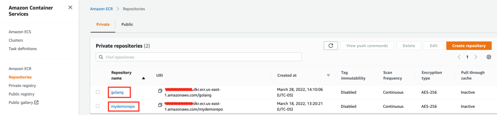
We’ll be setting up two Amazon ECR repositories. The first repository, “golang”, will hold the base image which we will be migrating from Docker hub. And the second repository, “mydemorepo”, will hold the final image for your sample application.

ECR Repositories with Source and Target image

Figure 2. ECR Repositories with Source and Target image.

Migrate your existing Docker image from Docker Hub to Amazon ECR

Note that for this post, I’ll be using golang:1.12-alpine as the base Docker image to be migrated to Amazon ECR.

Once you have your base repository setup, the next step is to pull the golang:1.12-alpine public image from docker hub to you laptop/Server.

To do that, log in to your local server where you have deployed all of the prerequisites. This includes the Docker engine, Git Client, AWS CLI, etc., and run the following command:

docker pull golang:1.12-alpine

Authenticate to your Amazon ECR private registry, and click here to learn more about private registry authentication.

aws ecr get-login-password --region us-east-1 | docker login --username AWS --password-stdin 12345678910.dkr.ecr.us-east-1.amazonaws.com

Apply the appropriate Tag to your image.

docker tag golang:1.12-alpine 12345678910.dkr.ecr.us-east-1.amazonaws.com/golang:1.12-alpine

Push your image to the Amazon ECR repository.

docker push 150359982618.dkr.ecr.us-east-1.amazonaws.com/golang:1.12-alpine

The Source Image

Figure 3. The Source Image.

Once your image gets pushed to Amazon ECR with all of the required tags, the next step is to use this base image as the source image to build our sample application. Furthermore, while going through the “Overview of the Solution” section, you might have noticed that we must have a source code repository for CodeBuild to fetch the latest code from, and to build a sample application. Let’s go through how to set up your source code repository.

Set up a source code repository using CodeCommit

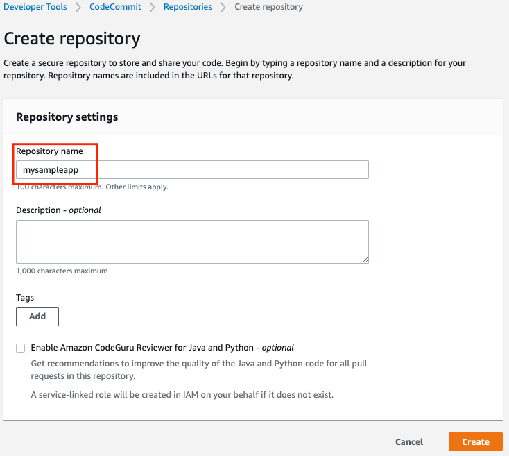
Let’s start by setting up the repository name. In this case, let’s call it “mysampleapp”. Keep rest of the settings as is, and then select create.

Screenshot for creating a repository under AWS Code Commit

Figure 4. Screenshot for creating a repository under AWS Code Commit.

Once the repository gets created, go to the top-right corner. Under Clone URL, select Clone HTTPS.

Clone URL to copy the code Locally on your desktop or server

Figure 5. Clone URL to copy the code Locally on your desktop or server.

Go back to your local server or laptop where you want to clone the repo, and authenticate your repository. Learn more about how to HTTPS connections to AWS Codecommit repositories.

git clone https://git-codecommit.us-east-1.amazonaws.com/v1/repos/mysampleapp mysampleapp

Note that you have your empty repository cloned locally with a folder name “mysampleapp”. The next step is to set up Dockerfile and buildspec.

Set up a Dockerfile and buildspec for building the base image of your Sample Application

To build a Docker image, we’ll set up three files under the “mysampleapp” folder.

Buildspec.yml
Dockerfile
README.md

List out the base code pushed to AWS Code commit

Figure 6. List out the base code pushed to AWS Code commit.

Note that I have also listed the content inside of buildspec.yml, Dockerfile, and ReadME.md in case you want a sample code to test the scenario.

buildspec.yml

version: 0.2
phases:
pre_build:
commands:
- echo Logging in to Amazon ECR...
- REPOSITORY_URI=12345678910.dkr.ecr.us-east-1.amazonaws.com/mydemorepo
- AWS_DEFAULT_REGION=us-east-1
- AWS_ACCOUNT_ID=12345678910
- aws ecr get-login-password --region $AWS_DEFAULT_REGION | docker login --username AWS --password-stdin $AWS_ACCOUNT_ID.dkr.ecr.$AWS_DEFAULT_REGION.amazonaws.com
- IMAGE_REPO_NAME=mydemorepo
- COMMIT_HASH=$(echo $CODEBUILD_RESOLVED_SOURCE_VERSION | cut -c 1-7)
- IMAGE_TAG=build-$(echo $CODEBUILD_BUILD_ID | awk -F":" '{print $2}')
build:
commands:
- echo Build started on `date`
- echo Building the Docker image...
- docker build -t $REPOSITORY_URI:latest .
- docker images
- docker tag $REPOSITORY_URI:latest $REPOSITORY_URI:$IMAGE_TAG
post_build:
commands:
- echo Build completed on `date`
- echo Pushing the Docker image...
- docker push $REPOSITORY_URI:latest
- docker push $REPOSITORY_URI:$IMAGE_TAG

Dockerfile

Point your Dockfile to use Amazon ECR repository instead of Docker hub.

FROM golang:1.12-alpine AS build << Replace the public Image with ECR private image

FROM 150359982618.dkr.ecr.us-east-1.amazonaws.com/golang: 1.12-alpine

AS build

#Install git

RUN apk add --no-cache git

#Get the hello world package from a GitHub repository

RUN go get github.com/golang/example/hello

WORKDIR /go/src/github.com/golang/example/hello

#Build the project and send the output to /bin/HelloWorld

RUN go build -o /bin/HelloWorld

README.md

> Demo Repository has files related to CodeBuild spec and Dockerfile

* buildspec.yaml
* Dockerfile

Now, commit your changes locally, and push them to Amazon ECR. Note that to learn more about how to set up HTTPS users using Git Credentials, click here.

git add .
git commit -m "My First Commit - Sample App"
git push -u origin master

Now, go back to your AWS Management Console, and Under Developer Tools, select CodeCommit. Go to mysampleapp, and you should see three files with the latest commits.

Screenshot with buildspec, Dockerfile and README.

Figure 7. Screenshot with buildspec, Dockerfile and README

That concludes our setup to CodeCommit. Next, we’ll set up a build project.

Set up a CodeBuild project

Enter the project name, in this case let’s use “mysamplbuild”.

Setting up a Build Project.

Figure 8. Setting up a Build Project.

Select the provider as CodeCommit, followed by the repository and the branch that contains the latest commit.

Selecting the source code provider which is Code Commit and the source repository.

Figure 9.  Selecting the source code provider which is Code Commit and the source repository.

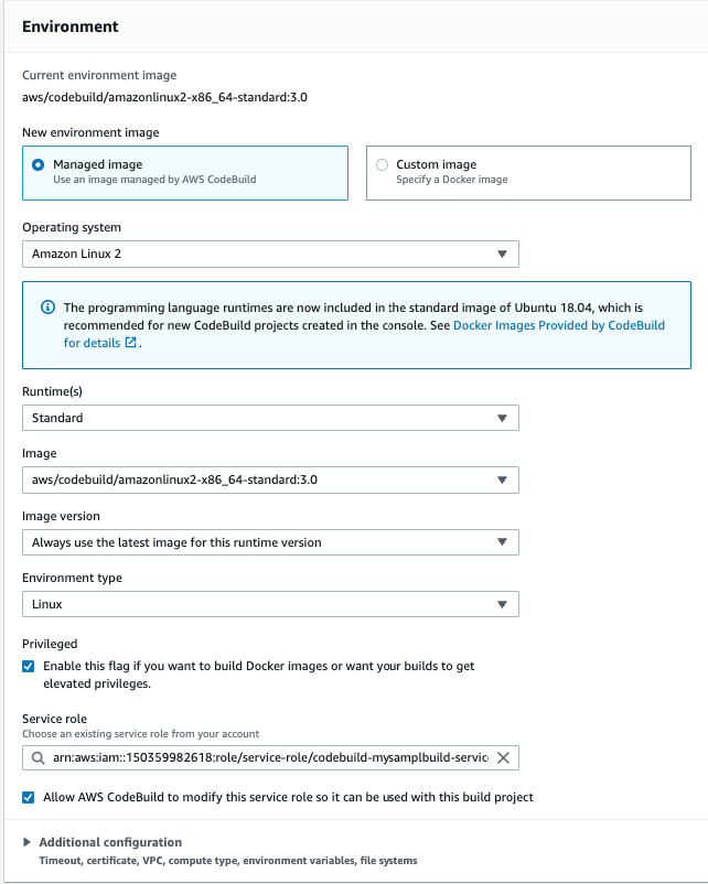
Select the runtime as standard, and then choose the latest Amazon Linux image. Make sure that the environment type is set to Linux. Privileged option should be checked. For the rest of the options, go with the defaults.

Required environment variables and attributes.

Figure 10.  Required environment variables and attributes.

Choose the buildspec.

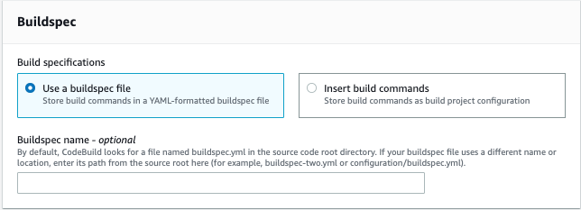
Figure 11.  Choose the buildspec.

Once the project gets created, select the project, and select start Build.

Screenshot of the build project along with details.

Figure 12. Screenshot of the build project along with details.

Once you trigger the build, you will notice that CodeBuild is pulling the image from Amazon ECR instead of Docker hub.

The log file for the build.

Figure 13. The log file for the build.

Clean up

To avoid incurring future charges, delete the resources.

Conclusion

Developers can use AWS to host both their private and public container images. This decreases the need to use different public websites and registries. Public images will be geo-replicated for reliable availability around the world, and they’ll offer fast downloads to quickly serve up images on-demand. Anyone (with or without an AWS account) will be able to browse and pull containerized software for use in their own applications.

Author:

Bijith Nair

Bijith Nair is a Solutions Architect at Amazon Web Services, Based out of Dallas, Texas. He helps customers architect, develop, scalable and highly available solutions to support their business innovation.

Configuring low latency connectivity between AWS Outposts rack and on-premises data using CoIP

Post Syndicated from Sheila Busser original https://aws.amazon.com/blogs/compute/configuring-low-latency-connectivity-between-aws-outposts-rack-using-coip-and-on-premises-data/

This blog post is written by, Leonardo Azize Martins, Cloud Infrastructure Architect, Professional Services.

AWS Outposts rack enables applications that need to run on-premises due to low latency, local data processing, or local data storage needs by connecting Outposts rack to your on-premises network via the local gateway (LGW).

Each Outpost rack includes a local gateway to provide low latency connectivity between the Outpost and any local data sources, end users, local machinery and equipment, or local databases. If you have an Outpost rack, you can include a local gateway as the target in your VPC subnet route table where the destination is your on-premises network. Local gateways are only available for Outposts rack and can only be used in route tables where the VPC has been associated with an LGW.

In a previous blog post on connecting AWS Outposts to on-premises data sources, you learned the different use cases to use AWS Outposts connected with your local network. In this post, you will dive deep into local gateway usage and specific details about it. You will learn how to use Outpost local gateway when it is configured as Customer-owned IP addresses (CoIP) mode. You will also learn how to integrate it with your Amazon Virtual Private Cloud (Amazon VPC) and how different routes work regarding Amazon Elastic Compute Cloud (Amazon EC2) instances running on Outposts.

Overview of solution

The primary role of a local gateway is to provide connectivity from an Outpost to your local on-premises LAN. It also provides AWS Outposts connectivity to the internet through your on-premises network via the LGW, so you don’t need to rely on an internet gateway (IGW). The local gateway can also provide a data plane path back to the AWS Region. If you already have connectivity between your LAN and the Region through AWS Site-to-Site VPN or AWS Direct Connect, you can use the same path to connect from the Outpost to the AWS Region privately.

Outpost subnet

Public subnets and private subnets are important concepts to understand for Outposts networking. A public subnet has a route to an internet gateway. The same concept applies to Outpost subnets, when a public subnet exists on Outposts, it will have a route to an internet gateway, which will use a service link as a communication path between an Outpost and the internet gateway in the parent AWS Region.

Outpost public route via internet gateway

A private subnet does not have a direct route to the internet gateway. It will only be local inside the VPC, or it could have a route to a Network Address Translation (NAT) gateway. In both cases, the communication between Outpost subnets and AWS Region subnets will be done via the service link.

Outpost private route via NAT gateway

Your subnet can be private and only be allowed to communicate with your on-premises network. You just need a route pointing to the LGW.

Outpost private route via LGW

You can also provide internet connectivity to your Outpost subnets via LGW. In this case, it will not use the service link. As soon as it traverses the LGW and goes to your next hop, it will follow your routing flow to the internet.

Outpost public route via LGW

Routing

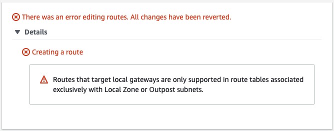
By default, every Outpost subnet inherits the main route table from its VPC. You can create a custom route table and associate it with an Outpost subnet. You can include a local gateway as the target when the destination is your on-premises network. A local gateway can only be used in VPC and subnet route tables that are exclusively associated with an Outpost subnet. If the route table is associated with an Outpost subnet and a Region subnet, it will not allow you to add a local gateway as the target.

Error message: addition of a local gateway as the target is denied

Local gateways are also not supported in the main route table.

Error message: routes that target local gateways not supported in main route table

The local gateway advertises Outpost IP address ranges to your on-premises network via BGP. In the other direction, from an on-premises network to the Outpost, it doesn’t use BGP, which means there is no propagation. You need to configure your VPC route table with static routes.

As of this writing, the LGW does not support jumbo frame.

Outposts IP addresses

Outposts can be configured in customer-owned IP (CoIP) mode.

Customer-owned IP

During the installation process, uses information that you provide about your on-premises network to create an address pool, which is known as a customer-owned IP address pool (CoIP pool). AWS then assigns it to the local gateway for use and advertises back to your on-premises network through BGP.

CoIP addresses provide local or external connectivity to resources in your Outpost subnets through your on-premises network. You can assign these IP addresses to resources on your Outpost, such as an EC2 instance, by allocating a new Elastic IP address from the customer-owned IP pool and then assigning this new Elastic IP address to your EC2 instance.

A local gateway serves as NAT for EC2 instances that have been assigned addresses from your customer-owned IP pool.

You can optionally share your customer-owned pool with multiple AWS accounts in your AWS Organizations using the AWS Resource Access Manager (RAM). After you share the pool, participants can allocate and associate Elastic IP addresses from the customer-owned IP pool.

Communication between your Outpost and on-premises network will use the CoIP Elastic IP addresses to address instances in the Outpost; the VPC CIDR range is not used.

Walkthrough

You will follow the steps required to configure your VPC to use LGW configured as CoIP, including:

  • Associate your VPC with the LGW route table.
  • Create an Outposts subnet.
  • Create and associate the VPC route table with the subnet.
  • Add a route to on-premises network with LGW as the target.

Prerequisites

For this walkthrough, you should have the following prerequisites:

  • An AWS account.
  • An Outpost that consists of one or more Outposts racks configured in CoIP mode.

Associate VPC with LGW route table

Use the following procedure to associate a VPC with the LGW route table. You can’t associate VPCs that have a CIDR block conflict.

  1. Open the AWS Outposts console.
  2. In the navigation pane, choose Local gateway route tables.
  3. Select the route table and then choose Actions, Associate VPC.
  4. For VPC ID, select the VPC to associate with the local gateway route table.
  5. Choose Associate VPC.

Create an Outpost subnet

You can add Outpost subnets to any VPC in the parent AWS Region for the Outpost. When you do so, the VPC also spans the Outpost.

  1. Open the AWS Outposts console.
  2. On the navigation pane, choose Outposts.
  3. Select the Outpost, and then choose Actions, Create subnet.
  4. Select the VPC and specify an IP address range for the subnet.
  5. Choose Create.

Create and associate VPC route table with the Outpost subnet

You can create a custom route table for your VPC using the Amazon VPC console. It is a best practice to have one specific route table for each subnet.

  1. Open the Amazon VPC console.
  2. In the navigation pane, choose Route Tables.
  3. Choose Create route table.
  4. For VPC, choose your VPC.
  5. Choose Create.
  6. On the Subnet associations tab, choose Edit subnet associations.
  7. Select the check box for the subnet to associate with the route table and then choose Save associations.

Add a route to on-premises network with LGW as the target

You can add a route to a route table using the Amazon VPC console.

  1. Open the Amazon VPC console.
  2. In the navigation pane, choose Route Tables and select
  3. Choose Actions, Edit routes.
  4. Choose Add route. For Destination, enter the destination CIDR block, a single IP address, or the ID of a prefix list.
  5. Choose Save routes.

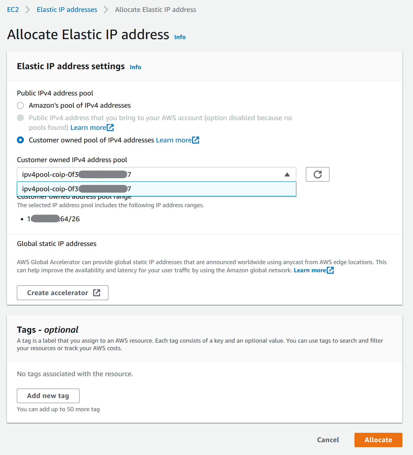
Allocate and associate a customer-owned IP address

  1. Open the Amazon EC2 console.
  2. In the navigation pane, choose Elastic IPs.
  3. Choose Allocate new address.
  4. For Network Border Group, select the location from which the IP address is advertised.
  5. For Public IPv4 address pool, choose Customer owned IPv4 address pool.
  6. For Customer owned IPv4 address pool, select the pool that you configured.
  7. Choose Allocate and close the confirmation screen.
  8. In the navigation pane, choose Elastic IPs.
  9. Select an Elastic IP address and choose Actions, Associate address.
  10. Select the instance from Instance and then choose Associate.

For more information about Launch an instance on your Outpost, refer to the AWS Outposts User Guide.

Allocate Elastic IP address

Cleaning up

To avoid incurring future charges, delete the resources, like EC2 instances.

Conclusion

In this post, I covered how to use the Outposts rack local gateway to communicate with your on-premises network. You learned how a subnet route table can influence the connectivity of public or private Outpost instances.

To learn more, check out our Outposts local gateway documentation and the networking reference architecture.

Understanding the lifecycle of Amazon EC2 Dedicated Hosts

Post Syndicated from Sheila Busser original https://aws.amazon.com/blogs/compute/understanding-the-lifecycle-of-amazon-ec2-dedicated-hosts/

This post is written by Benjamin Meyer, Sr. Solutions Architect, and Pascal Vogel, Associate Solutions Architect.

Amazon Elastic Compute Cloud (Amazon EC2) Dedicated Hosts enable you to run software on dedicated physical servers. This lets you comply with corporate compliance requirements or per-socket, per-core, or per-VM licensing agreements by vendors, such as Microsoft, Oracle, and Red Hat. Dedicated Hosts are also required to run Amazon EC2 Mac Instances.

The lifecycles and states of Amazon EC2 Dedicated Hosts and Amazon EC2 instances are closely connected and dependent on each other. To operate Dedicated Hosts correctly and consistently, it is critical to understand the interplay between Dedicated Hosts and EC2 Instances. In this post, you’ll learn how EC2 instances are reliant on their (dedicated) hosts. We’ll also dive deep into their respective lifecycles, the connection points of these lifecycles, and the resulting considerations.

What is an EC2 instance?

An EC2 instance is a virtual server running on top of a physical Amazon EC2 host. EC2 instances are launched using a preconfigured template called Amazon Machine Image (AMI), which packages the information required to launch an instance. EC2 instances come in various CPU, memory, storage and GPU configurations, known as instance types, to enable you to choose the right instance for your workload. The process of finding the right instance size is known as right sizing. Amazon EC2 builds on the AWS Nitro System, which is a combination of dedicated hardware and the lightweight Nitro hypervisor. The EC2 instances that you launch in your AWS Management Console via Launch Instances are launched on AWS-controlled physical hosts.

What is an Amazon EC2 Bare Metal instance?

Bare Metal instances are instances that aren’t using the Nitro hypervisor. Bare Metal instances provide direct access to physical server hardware. Therefore, they let you run legacy workloads that don’t support a virtual environment, license-restricted business-critical applications, or even your own hypervisor. Workloads on Bare Metal instances continue to utilize AWS Cloud features, such as Amazon Elastic Block Store (Amazon EBS), Elastic Load Balancing (ELB), and Amazon Virtual Private Cloud (Amazon VPC).

What is an Amazon EC2 Dedicated Host?

An Amazon EC2 Dedicated Host is a physical server fully dedicated to a single customer. With visibility of sockets and physical cores of the Dedicated Host, you can address corporate compliance requirements, such as per-socket, per-core, or per-VM software licensing agreements.

You can launch EC2 instances onto a Dedicated Host. Instance families such as M5, C5, R5, M5n, C5n, and R5n allow for the launching of different instance sizes, such as4xlarge and 8xlarge, to the same host. Other instance families only support a homogenous launching of a single instance size. For more details, see Dedicated Host instance capacity.

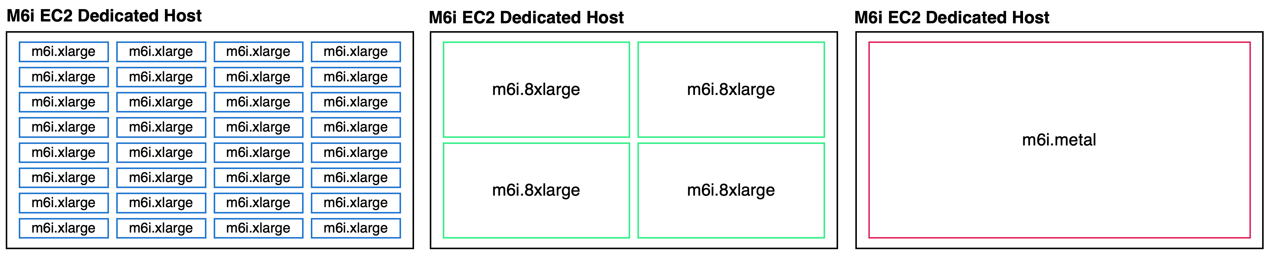
As an example, let’s look at an M6i Dedicated Host. M6i Dedicated Hosts have 2 sockets and 64 physical cores. If you allocate a M6i Dedicated Host, then you can specify what instance type you’d like to support for allocation. In this case, possible instance sizes are:

  • large
  • xlarge
  • 2xlarge
  • 4xlarge
  • 8xlarge
  • 12xlarge
  • 16xlarge
  • 24xlarge
  • 32xlarge
  • metal

The number of instances that you can launch on a single M6i Dedicated Host depends on the selected instance size. For example:

  • In the case of xlarge (4 vCPUs), a maximum of 32 m6i.xlarge instances can be scheduled on this Dedicated Host.
  • In the case of 8xlarge (32 vCPUs), a maximum of 4 m6i.8xlarge instances can be scheduled on this Dedicated Host.
  • In the case of metal (128 vCPUs), a maximum of 1 m6i.metal instance can be scheduled on this Dedicated Host.

When launching an EC2 instance on a Dedicated Host, you’re billed for the Dedicated Host but not for the instance. The cost for Amazon EBS volumes is the same as in the case of regular EC2 instances.

Exemplary homogenious M6i Dedicated Host shown with 32 m6i.xlarge, four m6i.8xlarge and one m6i.metal each.

Exemplary M6i Dedicated Host instance selections: m6i.xlarge, m6i.8xlarge and m6i.metal

Understanding the EC2 instance lifecycle

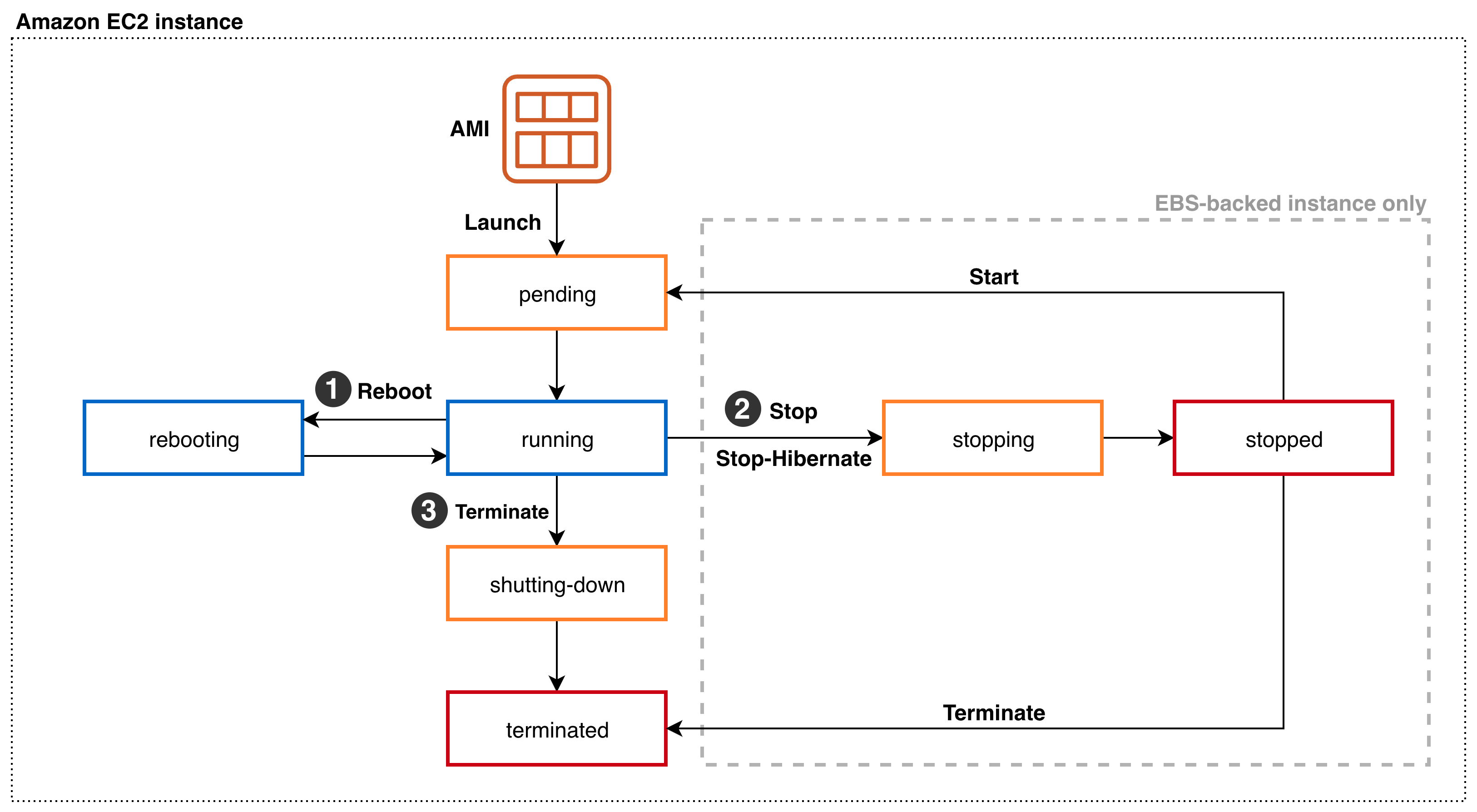
Amazon EC2 instance lifecycle states and transitions

Throughout its lifecycle, an EC2 instance transitions through different states, starting with its launch and ending with its termination. Upon Launch, an EC2 instance enters the pending state. You can only launch EC2 instances on Dedicated Hosts in the available state. You aren’t billed for the time that the EC2 instance is in any state other than running. When launching an EC2 instance on a Dedicated Host, you’re billed for the Dedicated Host but not for the instance. Depending on the user action, the instance can transition into three different states from the running state:

  1. Via Reboot from the running state, the instance enters the rebooting state. Once the reboot is complete, it reenters the running state.
  2. In the case of an Amazon EBS-backed instance, a Stop or Stop-Hibernate transitions the running instance into the stopping state. After reaching the stopped state, it remains there until further action is taken. Via Start, the instance will reenter the pending and subsequently the running state. Via Terminate from the stopped state, the instance will enter the terminated state. As part of a Stop or Stop-Hibernate and subsequent Start, the EC2 instance may move to a different AWS-managed host. On Reboot, it remains on the same AWS-managed host.
  3. Via Terminate from the running state, the instance will enter the shutting-down state, and finally the terminated state. An instance can’t be started from the terminated state.

Understanding the Amazon EC2 Dedicated Host lifecycle

A diagram of the the Amazon EC2 Dedicated Host lifecycle states and transitions between them.

Amazon EC2 Dedicated Host lifecycle states and transitions

An Amazon EC2 Dedicated Host enters the available state as soon as you allocate it in your AWS account. Only if the Dedicated Host is in the available state, you can launch EC2 instances on it. You aren’t billed for the time that your Dedicated Host is in any state other than available. From the available state, the following states and state transitions can be reached:

  1. You can Release the Dedicated Host, transitioning it into the released state. Amazon EC2 Mac Instances Dedicated Hosts have a minimum allocation time of 24h. They can’t be released within the 24h. You can’t release a Dedicated Host that contains instances in one of the following states: pending, running, rebooting, stopping, or shutting down. Consequently, you must Stop or Terminate any EC2 instances on the Dedicated Host and wait until it’s in the available state before being able to release it. Once an instance is in the stopped state, you can move it to a different Dedicated Host by modifying its Instance placement configuration.
  2. The Dedicated Host may enter the pending state due to a number of reasons. In case of an EC2 Mac instance, stopping or terminating a Mac instance initiates a scrubbing workflow of the underlying Dedicated Host, during which it enters the pending state. This scrubbing workflow includes tasks such as erasing the internal SSD, resetting NVRAM, and more, and it can take up to 50 minutes to complete. Additionally, adding or removing a Dedicated Host to or from a Resource Group can cause the Dedicated Host to go into the pending state. From the pending state, the Dedicated Host will reenter the available state.
  3. The Dedicated Host may enter the under-assessment state if AWS is investigating a possible issue with the underlying infrastructure, such as a hardware defect or network connectivity event. While the host is in the under-assessment state, all of the EC2 instances running on it will have the impaired status. Depending on the nature of the underlying issue and if it’s configured, the Dedicated Host will initiate host auto recovery.

If Dedicated Host Auto Recovery is enabled for your host, then AWS attempts to restart the instances currently running on a defect Dedicated Host on an automatically allocated replacement Dedicated Host without requiring your manual intervention. When host recovery is initiated, the AWS account owner is notified by email and by an AWS Health Dashboard event. A second notification is sent after the host recovery has been successfully completed. Initially, the replacement Dedicated Host is in the pending state. EC2 instances running on the defect dedicated Host remain in the impaired status throughout this process. For more information, see the Host Recovery documentation.

Once all of the EC2 instances have been successfully relaunched on the replacement Dedicated Host, it enters the available state. Recovered instances reenter the running state. The original Dedicated Host enters the released-permanent-failure state. However, if the EC2 instances running on the Dedicated Host don’t support host recovery, then the original Dedicated Host enters the permanent-failure state instead.

Conclusion

In this post, we’ve explored the lifecycles of Amazon EC2 instances and Amazon EC2 Dedicated Hosts. We took a close look at the individual lifecycle states and how both lifecycles must be considered in unison to operate EC2 Instances on EC2 Dedicated Hosts correctly and consistently. To learn more about operating Amazon EC2 Dedicated Hosts, visit the EC2 Dedicated Hosts User Guide.

Write Better Commits, Build Better Projects

Post Syndicated from Victoria Dye original https://github.blog/2022-06-30-write-better-commits-build-better-projects/

How often have you found yourself thinking:

  • What’s the point of this code?
  • Isn’t this option deprecated?
  • Is this comment out-of-date? I don’t think it describes what I’m seeing.
  • This pull request is massive, where do I start?
  • Where did this bug come from?

These questions all reflect the limitations of collaboratively-developed source code as a communication medium. While there are ways to mitigate these issues (code comments, style guides, documentation requirements), we still inevitably find ourselves spending hours on just trying to understand code. Luckily, the tools needed to solve these problems have been here all along!

Commits in Git repositories are more than just save points or logs of incremental progress in a larger project. In the words of GitHub’s “Git Guides“:

[Commits] are snapshots of your entire repository at specific times…based around logical units of change. Over time, commits should tell a story of the history of your repository and how it came to be the way that it currently is.

Commits are a firsthand historical record of exactly how and why each line of code came to be. They even come with human-readable messages! As a result, a repository’s commit history is the best tool a developer can use to explain and understand code.

It’s been my experience that commits are most effective when they’re tweaked and polished to deliberately convey a message to their audiences: reviewers, other contributors, and even your future self. This post will:

  1. Introduce some guidelines for organizing and revising commits.
  2. Outline pragmatic approaches for applying those guidelines.
  3. Describe some of the practical applications of a well-crafted commit history.

Writing better commits

Software development involves a lot of creativity, so your commits will reflect the context of your changes, your goals, and your personal style. The guidelines below are presented to help you utilize that creative voice to make your commits effective tools of communication.

As you read these guidelines, don’t worry about how you’ll be able to utilize all of this advice in the midst of writing code. Although you may naturally incorporate them into your development process with practice, each can be applied iteratively after you’ve written all of your code.

📚 Structure the narrative

Like your favorite novel, a series of commits has a narrative structure that contextualizes the “plot” of your change with the code. Before any polishing, the narrative of a branch typically reflects an improvised stream of consciousness. It might contain:

  • A commit working on component A, followed by one on component B, followed by one finishing component A
  • A multi-commit detour into trying again and again to get the right CI syntax
  • A commit fixing a typo from an earlier commit
  • A commit with a mixed bag of all of the review feedback
  • A merge commit resolving conflicts with the main branch

Although an accurate retelling of your journey, a branch like this tells a “story” that is neither coherent nor memorable.

The problem

Disorganized commits that eschew a clear narrative will affect two people: the reviewer, and the developer themself.

Reviewing commit-by-commit is the easiest way to avoid being overwhelmed by the changes in a sufficiently large pull request. If those commits do not tell a singular, easy-to-follow story, the reviewer will need to context-switch as the author’s commits jump from topic to topic. To ensure earlier commits properly set up later ones (for example, verifying a newly-created function is used properly), the reviewer ultimately needs to piece together the narrative on their own; for each commit, figure out which earlier changes establish the relevant background context and tediously click back and forth between them. Alternatively, they’ll remember some vague details and simply assume earlier commits properly set up later ones, failing to identify potential issues.

But how does a scatterbrained narrative hurt the developer? A developer’s first instinct when working on a new project is often to hack on it until they get something functional. Fluctuating between “fun” and “frustrating,” this approach eventually yields good results, but it’s far from efficient. Jumping in without a plan – the mindset of following a narrative – makes that process slower than it needs to be.

The solution

Outline your narrative, and reorganize your commits to match it.

The narrative told by your commits is the vehicle by which you convey the meaning of your changes. Also, like a story, it can take on many structures or forms.

Your branch is your story to tell. While the narrative is up to you, here are some editorial tips on how to keep it organized:

DO DON’T
Write an outline and include it in the pull request description. Wait until the end to form the outline – try using it to guide your work!
Stick to one high-level concept per branch. Go down a tangentially-related “rabbit hole”.
Add your “implement feature” commit immediately after the refactoring that sets it up. Jump back and forth between topics throughout your branch.
Treat commits as “building blocks” of different types: bugfix, refactor, stylistic change, feature, etc. Mix multiple building block types in a single commit.

⚛ Resize and stabilize the commits

Although the structure of a commit series can tell the high-level story of an author’s feature, it’s the code within each commit that creates software. Code itself can be complex, dense, and cryptic but in order to collaborate, others need to understand it.

The problem

The cognitive burden of parsing code is exacerbated by having either too much or not enough information presented at once. Too much, and your reader will need to read and understand multiple conceptually-different topics that could get jumbled, misinterpreted, or simply missed; too little, and your reader will develop an incomplete mental model of a change.

For a reviewer, one of the big benefits of a commit-by-commit review is – like individual lectures in a semester-long course – pacing the development of their mental model with small, easy-to-digest changes. When a large commit doesn’t provide that sustainable learning pace, the reviewer may fail fail to identify questionable architectural decisions because they conflate unrelated topics, or even miss a bug because it’s in a section seemingly irrelevant to the impacted feature.

You might think reviewers’ problems would be solved with commits as small as possible, but an incomplete change leaves them unable to evaluate it fully as they read it. When a later commit “completes” the change, a reviewer may not easily draw connections to the earlier context. This is made worse when a later commit undoes something from the earlier, partial commit. The “churn” in these situations leads to the same weakened mental model – and same consequences – as when dealing with too-large commits.

Poorly-sized commits present more tangible issues as well. Most apparent is the inability to roll back your repository to a commit (for example, when debugging a strange feature interaction). Incomplete changes often fail to build, so a developer will be stuck searching nearby commits for a fix. Similarly, a bug narrowed down to a massive commit requires teasing apart its intermixed changes, a potentially more difficult task than it was during the initial review due to loss of institutional project knowledge over time.

The solution

Make each commit both “small” and “atomic.”

To best convey your story, commits should minimize the effort needed to build a mental model of the changes they introduce. With effort tied to having a “just right” amount of information, the key to a good commit is fitting into quantified upper and lower bounds on that information.

A small commit is one with minimal scope; it does one “thing.” This often correlates to minimizing the modified lines of cone, but that isn’t a firm requirement. For example, changing the name of a commonly-used function may modify hundreds of lines of code, but its constrained scope makes it simple to both explain and review.

A commit is atomic when it is a stable, independent unit of change. In concrete terms, a repository should still build, pass tests, and generally function if rolled back to that exact commit without needing other changes. In an atomic commit, your reader will have everything they need to evaluate the change in the commit itself.

❓ Explain the context

Commits are more than just the code they contain. Despite there being no shortage of jokes about them, commit messages are an extremely valuable – but often overlooked – component of a commit. Most importantly, they’re an opportunity to speak directly to your audience and explain a change in your own terms.

The problem

Even with a clear narrative and appropriately-sized commits, a niche change can still leave readers confused. This is especially true in large or open-source projects, where a reviewer or other future reader (even yourself!) likely won’t be clued into the implementation details or nuances of the code you’ve changed.

Code is rarely as self-evident as the author may believe, and even simple changes can be prone to misinterpretation. For example, what may appear to be a bug may instead be a feature implemented to solve an unrelated problem. Without understanding the intent of the original change, a developer may inadvertently modify an expected user-facing behavior. Conversely, something that appears intentional may have been a bug in the first place. A misinterpretation could cause a developer to enshrine a small mistake as a “feature” that hurts user experience for years.

Even in a best-case scenario, poorly explained changes will slow down reviewers and contributors as they attempt to interpret code, unnecessarily wasting everyone’s time and energy.

The solution

Describe what you’re doing and why you’re doing it in the commit message.

Because you’re writing for an audience, the content of a commit message should clearly communicate what readers need to understand. As the developer, you should already know the background and implementation well enough to explain them. Rather than write excessively long (and prone to obsoletion) code comments or put everything into a monolithic pull request description, you can use commit messages to provide piecewise clarification to each change.

“What” and “why” break down further into high- and low-level details, all of which can be framed as four questions to answer in each commit message:

What you’re doing Why you’re doing it
High-level (strategic) Intent (what does this accomplish?) Context (why does the code do what it does now?)
Low-level (tactical) Implementation (what did you do to accomplish your goal?) Justification (why is this change being made?)

Building better projects

Using the guidelines established above, you can mitigate the challenges of common software development tasks including code review, finding bugs, and root cause analysis.

Code review

Reviewing even the largest pull requests can be a manageable, straightforward process if you are able to evaluate changes on a commit-by-commit basis. Each of the guidelines detailed earlier focuses on making the commits readable; to extract information from commits, you can use the guidelines as a template.

  1. Determine the narrative by reading the pull request description and list of commits. If the commits seem to jump between topics or address, leave a comment asking for clarification or changes.
  2. Lightly scan the message and contents of each commit, starting from the beginning of the branch. Verify smallness and atomicity by checking that the commit does one thing and that doesn’t include any incomplete implementations. Recommend splitting or combining commits that are incorrectly scoped.
  3. Thoroughly read each commit. Ensure the commit message sufficiently explains the code by first checking that implementation matches the intent, then that the code matches the stated implementation. Use the context and justification to guide your understanding of the code. If any of the requisite information is missing, ask for clarification from the author.
  4. Finally, with a complete mental model of the commit’s changes and the overarching narrative, confirm the code is efficient and bug-free.

Finding bugs with git bisect

If you’ve ever found yourself with a broken deployment and no idea when the breakage was introduced, git bisect is the tool for you. Specifically, git bisect is a tool built into Git that, when given a known-good commit (for example, your last stable deployment) and a known-bad commit (the broken one), will perform a binary search of the commits in the middle to find which one introduced the error.


As useful as git bisect is, it absolutely requires that each commit it traverses is both atomic and small. If not atomic, you will be unable to test for repository stability at each commit; if not small, the source commit of your bug may be so large that you end up inefficiently reading code line-by-line to find the bug anyway.

Root cause analysis

Suppose you’ve used something like git bisect to isolate the source commit of a bug. If you’re lucky, the underlying problem is obvious and you can fix it immediately. More often than not, things aren’t so simple; the bug-causing code might be necessary for another feature, or does not make sense as the source of the error you’re seeing. You need to understand why the code was written, and to do that, you can again use the commit history to investigate.

There are two main tools to help you search through commits: git blame and git log.

git blame annotates the file with the commit that last changed it:

$ git blame -s my-file.py
abd52642da46 my-file.py 1) import os
603ab927a0dd oldname.py 3) import re
603ab927a0dd oldname.py 4)
603ab927a0dd oldname.py 5) print(“Hello world”)
abd52642da46 my-file.py 5) print(os.stat(“README”))

This can be particularly helpful in finding which commits modify the same area of code, which you can then read to determine if they interact poorly.

For a more generalized commit search, you can use git log. In its simplest form, git log will display a list of commits in reverse chronological order, starting at HEAD:

$ git log --oneline
09823ba09de1 README.md: update project title
abd52642da46 my-file.py: add README stat printout
7392d7dbb9ae my-file.py: rename from oldname.py
5ad823d1bc48 test.py: commonize test setup
603ab927a0dd oldname.py: create printout script
...

The displayed list of commits can also be filtered by file(s), by function name, by line range in a file, by commit message text, and more. As with git blame, these filtered lists of commits can help you build a complete mental model of the changes that comprise a particular file or function, ultimately guiding you to the root cause of your bug.

Final thoughts

Although subjective and sometimes difficult to quantify, commit quality can make a massive difference in developer quality-of-life on any project: old or new, large or small, open- or closed-source. To make commit refinement part of your own development process, some guidelines to follow are:

  1. Organize your commits into a narrative.
  2. Make each commit both small and atomic.
  3. Explain the “what” and “why” of your change in the commit message.

These guidelines, as well as their practical applications, demonstrate how powerful commits can be when used to contextualize code. Regardless of what you do with them, commits will tell your project’s story; these strategies will help you make it a good one.

Additional Resources

Use AWS Nitro Enclaves to perform computation of multiple sensitive datasets

Post Syndicated from Sheila Busser original https://aws.amazon.com/blogs/compute/leveraging-aws-nitro-enclaves-to-perform-computation-of-multiple-sensitive-datasets/

This blog post is written by, Jeff Wisman, Principal Solutions Architect and Andrew Lee, Solutions Architect.

Introduction

Many organizations have sensitive datasets that they do not want to share with others because of stringent security and compliance requirements. However, they would still like to use each other’s data to perform processing and aggregation. For example, B2B (business to business) companies often want to augment their customer information dataset with additional demographic or psychographic signals. This enrichment of data is often done by one party sending customer information to be matched against another party’s data universe. Naturally, privacy and the revealing of business-critical customer information to an external entity is a major concern here. In this blog, we present a solution where multiple parties can choose to give an isolated compute environment access to their encrypted data to be decrypted and processed in a secure way using AWS Nitro Enclaves.

Designing and building your own secure private computing solution can be challenging, with few out-of-the-box solutions. Our sample application uses Nitro Enclaves, which support the creation of an isolated execution environment called an enclave and a cryptographic attestation process for generating and validating the enclave’s identity. The attestation process makes it possible to ensure only authorized code is running, as well as integration with the AWS Key Management Service (AWS KMS), so that only enclaves that you choose can access sensitive data. Nitro Enlaves enables customers to focus more on their application instead of worrying about integration with external services. While many enterprise use cases involve complex datasets, we’ll use a hypothetical scenario to learn the fundamentals of how this works. The example proof of concept (POC) application will be centered around a third-party bidding service for real estate transactions. Buyers will submit encrypted bids to the application. Once all the bids have been entered, the application will decrypt the bids, determine the highest bidder, and return a result without disclosing the actual bid amounts to any party.

How it works

The POC will be deployed across three AWS accounts, one each for buyer-1, buyer-2, and the bidding service. The bidding service will be run in an enclave on the bidding service’s account.

  1. The bidding service will generate a set of measurements called platform configuration registers (PCRs) from the application code that uses the attestation process. PCRs are cryptographic measurements that are unique to an enclave. An attestation document can be used to verify the identity of the enclave and establish trust.
  2. The buyers will each generate their own AWS KMS key and use AWS KMS to authorize cryptographic requests from the bidding service enclave based on PCR values in the attestation document.
  3. The buyers will place their bids into a file, encrypt the file using AWS KMS, and store them in their own Amazon Simple Storage Service (Amazon S3)
  4. The bidding service will run the application, which will retrieve the encrypted bids from each buyer’s S3 bucket, decrypt the bids, calculate the highest bidder, and store the result in an S3 bucket.

Overall workflow of POC

Implementation

Let’s take a deeper dive into the steps involved in implementing this POC. To deploy the POC to your environment, follow the instructions in the AWS Nitro Enclaves Bidding Service GitHub project.

Enclave image generation

The first step is for the bidding service to launch the parent instance that will host the enclave. Refer to Launch the parent instance for more information about this process. The two real estate buyers, which we will call buyer-1 and buyer-2, will need to review the application code of the enclave application and agree that their data will not be exposed outside the enclave. Once they agree on the code, the bidding service generates the enclave image and a set of measurements as part of the attestation process. The buyers should also perform this process to ensure that the enclave image was generated and its measurements are from the agreed-upon application code. During the generation process, a unique set of measurements is taken of the application, which will make up its identity. When the enclave makes a request to decrypt data with AWS KMS, those measurements will be included in an attestation document to prove the enclave’s identity. Access policies in AWS KMS can then grant access to that identity. An example of a set of measurements is shown here:

Enclave Image successfully created.
{ "Measurements": { "HashAlgorithm": "Sha384 { ... }",
"PCR0":"287b24930a9f0fe14b01a71ecdc00d8be8fad90f9834d547158854b8279c74095c43f8d7f047714e98deb7903f20e3dd",
"PCR1":"aca6e62ffbf5f7deccac452d7f8cee1b94048faf62afc16c8ab68c9fed8c38010c73a669f9a36e596032f0b973d21895",
"PCR2":"0315f483ae1220b5e023d8c80ff1e135edcca277e70860c31f3003b36e3b2aaec5d043c9ce3a679e3bbd5b3b93b61d6f"
} }

Preparing encrypted data

Each buyer will create an AWS KMS key and use that key to encrypt their bids. The encrypted bids will be stored in their respective S3 buckets. Because AWS KMS integrates with Nitro Enclaves to provide built-in attestation support, each buyer can add the PCR values generated earlier as a condition to their respective AWS KMS key policies. This will ensure that only the enclave application code agreed upon by both buyers will have access to utilize the keys for decryption. The following is an example of a KMS key policy with PCR values as a condition:

{
  "Version": "2012-10-17",
  "Id": "key-default-1",
  "Statement": [{
    "Sid": "Enable decrypt from enclave",
    "Effect": "Allow",
    "Principal": < PARENT INSTANCE ROLE ARN > ,
    "Action": "kms:Decrypt",
    "Resource": "",
    "Condition": {
      "StringEqualsIgnoreCase": {
        "kms:RecipientAttestation:ImageSha384": "<PCR0 VALUE FROM BUILDING ENCLAVE IMAGE>",
        "kms:RecipientAttestation:PCR1":"<PCR1 VALUE FROM BUILDING ENCLAVE IMAGE>",
        "kms:RecipientAttestation:PCR2":"<PCR2 VALUE FROM BUILDING ENCLAVE IMAGE>"
      }
    }
  }]
}

The previous example only shows a key policy that uses PCR0, PCR1, and PCR2. You can further scope down the permissions by adding additional PCR values, for instance, role, parent instance ID, and a signing certificate for the enclave image. Refer to the AWS Nitro Enclaves User Guide for more details about PCR values.

Running the POC

The bidding service will run the enclave image generated earlier on the parent instance. The application runs as two parts, one part on the parent instance and another in the enclave. Communication between the parent and the enclave is done through a vsock connection. An AWS KMS proxy is also used on the parent to allow communication between the enclave and AWS KMS for decrypting data. The parent application will retrieve the encrypted bids from each buyer’s S3 bucket and send them to the enclave. The enclave will decrypt the data using both buyers’ AWS KMS keys and present attestation documents signed by the Nitro Hypervisor. AWS KMS will validate that the PCR values in the attestation documents match the key policy before performing the decryption. The decryption event will be logged in AWS CloudTrail for auditing purposes. Once the encrypted bids are decrypted, the values are compared, and the winning buyer is recorded in the result. The unencrypted result is then returned to the parent and written to an S3 bucket in the bidding service’s account. A diagram of this process is shown in Figure 2.

Cleanup

Be sure you delete all the resources that were created when following the included Github project:

  • Bidding service EC2 instance EC2 instance IAM role and policy
  • AWS KMS Customer managed keys
  • S3 Buckets for storing encrypted files

Conclusion

In this blog post, we introduced a sample POC utilizing Nitro Enclaves to allow a bidding service to process two parties’ encrypted data without revealing their data to any party. We did this by ensuring access to sensitive data is only allowed from an application running within an enclave. With the straightforward integration of AWS KMS and the attestation process, customers can quickly develop applications on Nitro Enclaves that can enable computing on encrypted datasets from multiple accounts. For more information on AWS Nitro Enclaves, see the official product documentation or the introductory videos on YouTube.

Jenkins high availability and disaster recovery on AWS

Post Syndicated from James Bland original https://aws.amazon.com/blogs/devops/jenkins-high-availability-and-disaster-recovery-on-aws/

We often hear from customers about their challenges architecting Jenkins for scale and high availability (HA). Jenkins was originally built as a continuous integration (CI) system to test software before it was committed to a repository. Since its beginning, Jenkins has grown out of necessity versus grand master plan. Developers who extended Jenkins favored speed of creating functionality over performance or scalability of the entire system. This is not to say that it’s impossible to scale Jenkins, it’s only mentioned here to highlight the challenges and technical debt that has accumulated because of the prioritization of features versus developing towards a specific architecture. In this post, we discuss these challenges and our proposed solution.

Challenges with Jenkins at scale and HA

Business and customer demand are forcing organizations to increase the speed and agility at which they release features and functionality. As organizations make this transition, the usage of continuous integration and continuous delivery (CI/CD) increases, which drives the need to scale Jenkins. Overlay this with an organization that commits hundreds of changes per day and works around the clock, with developers dispersed globally, and you end up with an operational situation where there is no room for downtime. To mitigate the risk of impacting an organization’s ability to release when they need it, developers require a system that not only scales but is also highly available.

The ability to scale Jenkins and provide HA comes down to two problems. One is the ability to scale compute to handle additional jobs, and the second is storage. To scale compute, we typically do it in one of two ways, horizontally or vertically. Horizontally means we scale Jenkins to add additional compute nodes. Scaling vertically means we scale Jenkins by adding more resources to the compute node.

Let’s start with the storage problem. Jenkins is designed around the local file system. Anyone who has spent time around Jenkins is aware that logs, cloned repos, plugins, and build artifacts are stored into JENKINS_HOME. Local file systems, while good for single-server designs, tend to be a challenge when HA comes into the picture. In on-premises designs, administrators have often used Network File System (NFS) and Storage Area Networks (SAN) to achieve some scale and resiliency. This type of design comes with a trade-off of performance and doesn’t provide the true HA and inherent disaster recovery (DR) required to meet the demands of the business.

Because of the local file system constraint, there are two native families of storage available in AWS: Amazon Elastic Block Store (Amazon EBS) and Amazon Elastic File System (Amazon EFS). Amazon EBS is great for a single-server design in a single Availability Zone. The challenge is trying to scale a single-server design to support HA. Because of the requirement to assign an EBS volume to a specific Availability Zone, you can’t automatically transition the EBS volume to another Availability Zone and attach it to a Jenkins instance. If you don’t mind having an impact on Recovery Time Objective (RTO) and Recovery Point Objective (RPO), a solution using Amazon EBS snapshots copied to additional Availability Zones might work. Although EBS snapshot copy is possible, it’s not a recommended solution because it doesn’t scale and has complexities in building and maintaining this type of solution.

Amazon EFS as an alternative has worked well for customers that don’t have high usage patterns of Jenkins. All Jenkins instances within the Region can access the Amazon EFS file system and data durably stored in multiple Availability Zones. If a single Availability Zone experiences an outage, the Jenkins file system is still accessible from other Availability Zones providing HA for the storage layer. This solution is not recommended for high-usage systems due to the way that Jenkins reads and writes data. Jenkins’s access pattern is skewed towards writing data such as logs, cloned repos, and building artifacts versus reading data. Amazon EFS, on the other hand, is designed for workloads that read more than they write. On high-usage workloads, customers have experienced Jenkins build slowness and Jenkins page load latency. This is why Amazon EFS isn’t recommended for high-usage Jenkins systems.

Solution for Jenkins at scale and HA

Solving the compute problem is relatively straightforward by using Amazon Elastic Kubernetes Service (Amazon EKS). In the context of Jenkins, an organization would run Jenkins in an Amazon EKS cluster that spans multiple Availability Zones, as shown in the following diagram.

Diagram showing Jenkins deployment in Amazon EKS with three availability zones inside a VPC

Figure 1 –Jenkins deployment in Amazon EKS with multiple availability zones.

Jenkins Controller and Agent would run in an Availability Zone as a Kubernetes pod. Amazon EKS is designed around Desired State Configuration (DSC), which means that it continuously make sure that the running environment matches the configuration that has been applied to Amazon EKS. In practice, when Amazon EKS is told that you want a single pod of Jenkins running, it monitors and makes sure that pod is always running. If an Availability Zone is unavailable, Amazon EKS launches a new node in another Availability Zone and deploys all pods to meet any necessary constraints defined in Amazon EKS. With this option, we still need to have the data in other Availability Zones, which we cover later in this post.

The only option of scaling Jenkins controllers is vertical. Scaling Jenkins horizontally could lead to an undesirable state because the system wasn’t designed to have multiple instances of Jenkins attached to the same storage layer. There is no exclusive file locking mechanism to ensure data consistency. For organizations that have exhausted the limits with vertical scaling, the recommendation is to run multiple independent Jenkins controllers and separate them per team or group. Vertical scaling of Jenkins is simpler in Amazon EKS. Node sizes and container memory are controlled by configuration. Increasing memory size is as simple as changing a container’s memory setting. Due to the ease of changing configuration, it’s best to start with a lower memory setting, monitor performance, and increase as necessary. You want to find a good balance between price and performance.

For Jenkins agents, there are many options to scale the compute. In the context of scale and HA, the best options are to use AWS CodeBuild, AWS Fargate for Amazon EKS, or Amazon EKS managed node groups. With CodeBuild, you don’t need to provision, manage, or scale your build servers. CodeBuild scales continuously and processes multiple builds concurrently. You can use the Jenkins plugin for CodeBuild to integrate CodeBuild with Jenkins. Fargate is a good option but has some challenges if you’re trying to build container images within a container due to permissions necessary that aren’t exposed in Fargate. For additional information on how to overcome this challenge with Jenkins, refer to How to build container images with Amazon EKS on Fargate.

Now let’s look at the storage layer and see how LINBIT is helping organizations solve this problem with LINSTOR. LINBIT’s LINSTOR is an open-source management tool designed to manage block storage devices. Its primary use case is to provide Linux block storage for Kubernetes and other public and private cloud platforms. LINBIT also provides enterprise subscription for LINSTOR, which include technical support with SLA.

The following diagram illustrates a LINSTOR storage solution running on Amazon EKS using multiple Availability Zones and Amazon Simple Storage Service (Amazon S3) for snapshots.

Diagram showing LINSTOR storage solution running on Amazon EKS across three availability zone with snapshot stored in Amazon S3.

Figure 2. LINSTOR storage solution running on Amazon EKS using multiple availability zones and S3 for snapshot.

LINSTOR is composed of a control plane and a data plane. The control plane consists of a set of containers deployed into Amazon EKS and is responsible for managing the data plane. The data plane consists of a collection of open-source block storage software, most importantly LINBIT’s Distributed Replicated Storage System (DRBD) software. DRBD is responsible for provisioning and synchronously replicating storage between Amazon EKS worker instances in different Availability Zones.

LINSTOR is deployed via Helm into Amazon EKS, and the LINSTOR cluster is initialized by the LINSTOR Operator. Once deployed, LINSTOR volumes and volume snapshots are managed via Kubernetes Storage Classes and Snapshot Classes in a Kubernetes native fashion. LINSTOR volumes are backed by LINSTOR objects known as storage pools, which are composed of one or more EBS volumes attached to each Amazon EKS worker instance.

LINSTOR volumes layer DRBD on top of the worker’s attached EBS volume to enable synchronous replication between peers in the Amazon EKS cluster. This ensures that you have an identical copy of your persistent volume on the EBS volumes in each Availability Zone. In the event of an Availability Zone outage or planned migration, Amazon EKS moves the Jenkins deployment to another Availability Zone where the persistent volume copy is available. In terms of scaling, LINBIT DRDB supports up to 32 replicas per volume, with a maximum size of 1 PiB per volume. LINSTOR node itself can scale beyond hundreds of nodes, as shown in this case study.

LINSTOR also provides an HA Controller component in its control plane to speed up failover times during outages. LINSTOR’s HA Controller looks for pods with a specific label, and if LINSTOR’s persistent volumes replication network becomes interrupted (like during an Availability Zone outage), LINSTOR reschedules the pod sooner than the default Kubernetes pod-eviction-timeout.

LINBIT provides a detailed full installation for Jenkins HA in AWS. A sample of LINSTOR’s helm values supporting these features is as follows:

operator:
  satelliteSet:
    storagePools:
      lvmThinPools:
      - name: lvm-thin
        thinVolume: thinpool
        volumeGroup: ""
        devicePaths:
        - /dev/nvme1n1
    kernelModuleInjectionMode: Compile
stork:
  enabled: false
csi:
  enableTopology: true
etcd:
  replicas: 3
haController:
  replicas: 3

After LINSTOR is deployed, you create a Kubernetes StorageClass supporting persistent volumes with three replicas using the following example:

apiVersion: storage.k8s.io/v1
kind: StorageClass
metadata:
  name: "linstor-csi-lvm-thin-r3"
provisioner: linstor.csi.linbit.com
parameters:
  allowRemoteVolumeAccess: "false"
  autoPlace: "3"
  storagePool: "lvm-thin"
  DrbdOptions/Disk/disk-flushes: "no"
  DrbdOptions/Disk/md-flushes: "no"
  DrbdOptions/Net/max-buffers: "10000"
reclaimPolicy: Retain
allowVolumeExpansion: true
volumeBindingMode: WaitForFirstConsumer

Finally, Jenkins helm charts are deployed into Amazon EKS with the following Helm values to request a PV from the LINSTOR StorageClass:

persistence:
  storageClass: linstor-csi-lvm-thin-r3
  size: "200Gi"
controller:
  serviceType: LoadBalancer
  podLabels:
    linstor.csi.linbit.com/on-storage-lost: remove

To protect against entire AWS Region outages and provide disaster recovery, LINSTOR takes volume snapshots and replicates it cross-Region using Amazon S3. LINSTOR requires read and write access to the target S3 bucket using AWS credentials provided as Kubernetes secrets:

kind: Secret
apiVersion: v1
metadata:
  name: linstor-csi-s3-access
  namespace: default
type: linstor.csi.linbit.com/s3-credentials.v1
immutable: true
stringData:
  access-key: REDACTED
  secret-key: REDACTED

The target S3 bucket is referenced as a snapshot shipping target using a LINSTOR S3 VolumeSnapshotClass. The following example shows a VolumeSnapshotClass referencing the S3 bucket’s secret and additional configuration for the target S3 bucket:

kind: VolumeSnapshotClass
apiVersion: snapshot.storage.k8s.io/v1
metadata:
  name: linstor-csi-snapshot-class-s3
driver: linstor.csi.linbit.com
deletionPolicy: Delete
parameters:
  snap.linstor.csi.linbit.com/type: S3
  snap.linstor.csi.linbit.com/remote-name: s3-us-west-2
  snap.linstor.csi.linbit.com/allow-incremental: "false"
  snap.linstor.csi.linbit.com/s3-bucket: name-of-bucket-123
  snap.linstor.csi.linbit.com/s3-endpoint: http://s3.us-west-2.amazonaws.com
  snap.linstor.csi.linbit.com/s3-signing-region: us-west-2
  snap.linstor.csi.linbit.com/s3-use-path-style: "false"
  # Secret to store access credentials
  csi.storage.k8s.io/snapshotter-secret-name: linstor-csi-s3-access
  csi.storage.k8s.io/snapshotter-secret-namespace: default

Jenkins deployment persistent volume claim (PVC) is stored as a snapshot in Amazon S3 by using a standard Kubernetes volumeSnapshot definition with LINSTOR’s snapshot class for Amazon S3:

apiVersion: snapshot.storage.k8s.io/v1
kind: VolumeSnapshot
metadata:
  name: jenkins-dr-snapshot-0
spec:
  volumeSnapshotClassName: linstor-csi-snapshot-class-s3
  source:
    persistentVolumeClaimName: <jenkins-pvc-name>

Conclusion

In this post, we explained  the challenges to scale Jenkins for HA and DR. We also reviewed Jenkins storage architecture with Amazon EBS and Amazon EFS and where to apply these. We demonstrated how you can use Amazon EKS to scale Jenkins compute for HA and how AWS partner solutions such as LINBIT LINSTOR can help scale Jenkins storage for HA and DR. Combining both solutions can help organizations maintain their ability to deploy software with speed and agility. We hope you found this post useful as you think through building your CI/CD infrastructure in AWS. To learn more about running Jenkins in Amazon EKS, check out Orchestrate Jenkins Workloads using Dynamic Pod Autoscaling with Amazon EKS. To find out more information about LINBIT’s LINSTOR, check the Jenkins technical guide.

Authors:

James Bland

James is a 25+ year veteran in the IT industry helping organizations from startups to ultra large enterprises achieve their business objectives. He has held various leadership roles in software development, worldwide infrastructure automation, and enterprise architecture. James has been
practicing DevOps long before the term became popularized. He holds a doctorate in computer science with a focus on leveraging machine learning algorithms for scaling systems. In his current role at AWS as the APN Global Tech Lead for DevOps, he works with partners to help shape the future of technology.

Welly Siauw

Welly Siauw is a Sr. Partner Solution Architect at Amazon Web Services (AWS). He spends his day working with customers and partners, solving architectural challenges. He is passionate about service integration and orchestration, serverless and artificial intelligence (AI) and machine learning (ML). He authored several AWS blogs and actively leading AWS Immersion Days and Activation Days. Welly spends his free time tinkering with espresso machine and outdoor hiking.

Matt Kereczman

Matt Kereczman is a Solutions Architect at LINBIT with a long history of Linux System Administration and Linux System Engineering. Matt is a cornerstone in LINBIT’s technical team, and plays an important role in making LINBIT and LINBIT’s customer’s solutions great. Matt was President of the GNU/Linux Club at Northampton Area Community College prior to graduating with Honors from Pennsylvania College of Technology with a BS in Information Security. Open Source Software and Hardware are at the core of most of Matt’s hobbies.

Multi-Region Terraform Deployments with AWS CodePipeline using Terraform Built CI/CD

Post Syndicated from Lerna Ekmekcioglu original https://aws.amazon.com/blogs/devops/multi-region-terraform-deployments-with-aws-codepipeline-using-terraform-built-ci-cd/

As of February 2022, the AWS Cloud spans 84 Availability Zones within 26 geographic Regions, with announced plans for more Availability Zones and Regions. Customers can leverage this global infrastructure to expand their presence to their primary target of users, satisfying data residency requirements, and implementing disaster recovery strategy to make sure of business continuity. Although leveraging multi-Region architecture would address these requirements, deploying and configuring consistent infrastructure stacks across multi-Regions could be challenging, as AWS Regions are designed to be autonomous in nature. Multi-region deployments with Terraform and AWS CodePipeline can help customers with these challenges.

In this post, we’ll demonstrate the best practice for multi-Region deployments using HashiCorp Terraform as infrastructure as code (IaC), and AWS CodeBuild , CodePipeline as continuous integration and continuous delivery (CI/CD) for consistency and repeatability of deployments into multiple AWS Regions and AWS Accounts. We’ll dive deep on the IaC deployment pipeline architecture and the best practices for structuring the Terraform project and configuration for multi-Region deployment of multiple AWS target accounts.

You can find the sample code for this solution here

Solutions Overview

Architecture

The following architecture diagram illustrates the main components of the multi-Region Terraform deployment pipeline with all of the resources built using IaC.

DevOps engineer initially works against the infrastructure repo in a short-lived branch. Once changes in the short-lived branch are ready, DevOps engineer gets them reviewed and merged into the main branch. Then, DevOps engineer git tags the repo. For any future changes in the infra repo, DevOps engineer repeats this same process.

Git tags named “dev_us-east-1/research/1.0”, “dev_eu-central-1/research/1.0”, “dev_ap-southeast-1/research/1.0”, “dev_us-east-1/risk/1.0”, “dev_eu-central-1/risk/1.0”, “dev_ap-southeast-1/risk/1.0” corresponding to the version 1.0 of the code to release from the main branch using git tagging. Short-lived branch in between each version of the code, followed by git tags corresponding to each subsequent version of the code such as version 1.1 and version 2.0.”

Fig 1. Tagging to release from the main branch.

  1. The deployment is triggered from DevOps engineer git tagging the repo, which contains the Terraform code to be deployed. This action starts the deployment pipeline execution.
    Tagging with ‘dev_us-east-1/research/1.0’ triggers a pipeline to deploy the research dev account to us-east-1. In our example git tag ‘dev_us-east-1/research/1.0’ contains the target environment (i.e., dev), AWS Region (i.e. us-east-1), team (i.e., research), and a version number (i.e., 1.0) that maps to an annotated tag on a commit ID. The target workload account aliases (i.e., research dev, risk qa) are mapped to AWS account numbers in the environment configuration files of the infra repo in AWS CodeCommit.
The central tooling account contains the CodeCommit Terraform infra repo, where DevOps engineer has git access, along with the pipeline trigger, the CodePipeline dev pipeline consisting of the S3 bucket with Terraform infra repo and git tag, CodeBuild terraform tflint scan, checkov scan, plan and apply. Terraform apply points using the cross account role to VPC containing an Application Load Balancer (ALB) in eu-central-1 in the dev target workload account. A qa pipeline, a staging pipeline, a prod pipeline are included along with a qa target workload account, a staging target workload account, a prod target workload account. EventBridge, Key Management Service, CloudTrail, CloudWatch in us-east-1 Region are in the central tooling account along with Identity Access Management service. In addition, the dev target workload account contains us-east-1 and ap-southeast-1 VPC’s each with an ALB as well as Identity Access Management.

Fig 2. Multi-Region AWS deployment with IaC and CI/CD pipelines.

  1. To capture the exact git tag that starts a pipeline, we use an Amazon EventBridge rule. The rule is triggered when the tag is created with an environment prefix for deploying to a respective environment (i.e., dev). The rule kicks off an AWS CodeBuild project that takes the git tag from the AWS CodeCommit event and stores it with a full clone of the repo into a versioned Amazon Simple Storage Service (Amazon S3) bucket for the corresponding environment.
  2. We have a continuous delivery pipeline defined in AWS CodePipeline. To make sure that the pipelines for each environment run independent of each other, we use a separate pipeline per environment. Each pipeline consists of three stages in addition to the Source stage:
    1. IaC linting stage – A stage for linting Terraform code. For illustration purposes, we’ll use the open source tool tflint.
    2. IaC security scanning stage – A stage for static security scanning of Terraform code. There are many tooling choices when it comes to the security scanning of Terraform code. Checkov, TFSec, and Terrascan are the commonly used tools. For illustration purposes, we’ll use the open source tool Checkov.
    3. IaC build stage – A stage for Terraform build. This includes an action for the Terraform execution plan followed by an action to apply the plan to deploy the stack to a specific Region in the target workload account.
  1. Once the Terraform apply is triggered, it deploys the infrastructure components in the target workload account to the AWS Region based on the git tag. In turn, you have the flexibility to point the deployment to any AWS Region or account configured in the repo.
  2. The sample infrastructure in the target workload account consists of an AWS Identity and Access Management (IAM) role, an external facing Application Load Balancer (ALB), as well as all of the required resources down to the Amazon Virtual Private Cloud (Amazon VPC). Upon successful deployment, browsing to the external facing ALB DNS Name URL displays a very simple message including the location of the Region.

Architectural considerations

Multi-account strategy

Leveraging well-architected multi-account strategy, we have a separate central tooling account for housing the code repository and infrastructure pipeline, and a separate target workload account to house our sample workload infra-architecture. The clean account separation lets us easily control the IAM permission for granular access and have different guardrails and security controls applied. Ultimately, this enforces the separation of concerns as well as minimizes the blast radius.

A dev pipeline, a qa pipeline, a staging pipeline and, a prod pipeline in the central tooling account, each targeting the workload account for the respective environment pointing to the Regional resources containing a VPC and an ALB.

Fig 3. A separate pipeline per environment.

The sample architecture shown above contained a pipeline per environment (DEV, QA, STAGING, PROD) in the tooling account deploying to the target workload account for the respective environment. At scale, you can consider having multiple infrastructure deployment pipelines for multiple business units in the central tooling account, thereby targeting workload accounts per environment and business unit. If your organization has a complex business unit structure and is bound to have different levels of compliance and security controls, then the central tooling account can be further divided into the central tooling accounts per business unit.

Pipeline considerations

The infrastructure deployment pipeline is hosted in a central tooling account and targets workload accounts. The pipeline is the authoritative source managing the full lifecycle of resources. The goal is to decrease the risk of ad hoc changes (e.g., manual changes made directly via the console) that can’t be easily reproduced at a future date. The pipeline and the build step each run as their own IAM role that adheres to the principle of least privilege. The pipeline is configured with a stage to lint the Terraform code, as well as a static security scan of the Terraform resources following the principle of shifting security left in the SDLC.

As a further improvement for resiliency and applying the cell architecture principle to the CI/CD deployment, we can consider having multi-Region deployment of the AWS CodePipeline pipeline and AWS CodeBuild build resources, in addition to a clone of the AWS CodeCommit repository. We can use the approach detailed in this post to sync the repo across multiple regions. This means that both the workload architecture and the deployment infrastructure are multi-Region. However, it’s important to note that the business continuity requirements of the infrastructure deployment pipeline are most likely different than the requirements of the workloads themselves.

A dev pipeline in us-east-1, a dev pipeline in eu-central-1, a dev pipeline in ap-southeast-1, all in the central tooling account, each pointing respectively to the regional resources containing a VPC and an ALB for the respective Region in the dev target workload account.

Fig 4. Multi-Region CI/CD dev pipelines targeting the dev workload account resources in the respective Region.

Deeper dive into Terraform code

Backend configuration and state

As a prerequisite, we created Amazon S3 buckets to store the Terraform state files and Amazon DynamoDB tables for the state file locks. The latter is a best practice to prevent concurrent operations on the same state file. For naming the buckets and tables, our code expects the use of the same prefix (i.e., <tf_backend_config_prefix>-<env> for buckets and <tf_backend_config_prefix>-lock-<env> for tables). The value of this prefix must be passed in as an input param (i.e., “tf_backend_config_prefix”). Then, it’s fed into AWS CodeBuild actions for Terraform as an environment variable. Separation of remote state management resources (Amazon S3 bucket and Amazon DynamoDB table) across environments makes sure that we’re minimizing the blast radius.


-backend-config="bucket=${TF_BACKEND_CONFIG_PREFIX}-${ENV}" 
-backend-config="dynamodb_table=${TF_BACKEND_CONFIG_PREFIX}-lock-${ENV}"
A dev Terraform state files bucket named 

<prefix>-dev, a dev Terraform state locks DynamoDB table named <prefix>-lock-dev, a qa Terraform state files bucket named <prefix>-qa, a qa Terraform state locks DynamoDB table named <prefix>-lock-qa, a staging Terraform state files bucket named <prefix>-staging, a staging Terraform state locks DynamoDB table named <prefix>-lock-staging, a prod Terraform state files bucket named <prefix>-prod, a prod Terraform state locks DynamoDB table named <prefix>-lock-prod, in us-east-1 in the central tooling account” width=”600″ height=”456″>
 <p id=Fig 5. Terraform state file buckets and state lock tables per environment in the central tooling account.

The git tag that kicks off the pipeline is named with the following convention of “<env>_<region>/<team>/<version>” for regional deployments and “<env>_global/<team>/<version>” for global resource deployments. The stage following the source stage in our pipeline, tflint stage, is where we parse the git tag. From the tag, we derive the values of environment, deployment scope (i.e., Region or global), and team to determine the Terraform state Amazon S3 object key uniquely identifying the Terraform state file for the deployment. The values of environment, deployment scope, and team are passed as environment variables to the subsequent AWS CodeBuild Terraform plan and apply actions.

-backend-config="key=${TEAM}/${ENV}-${TARGET_DEPLOYMENT_SCOPE}/terraform.tfstate"

We set the Region to the value of AWS_REGION env variable that is made available by AWS CodeBuild, and it’s the Region in which our build is running.

-backend-config="region=$AWS_REGION"

The following is how the Terraform backend config initialization looks in our AWS CodeBuild buildspec files for Terraform actions, such as tflint, plan, and apply.

terraform init -backend-config="key=${TEAM}/${ENV}-
${TARGET_DEPLOYMENT_SCOPE}/terraform.tfstate" -backend-config="region=$AWS_REGION"
-backend-config="bucket=${TF_BACKEND_CONFIG_PREFIX}-${ENV}" 
-backend-config="dynamodb_table=${TF_BACKEND_CONFIG_PREFIX}-lock-${ENV}"
-backend-config="encrypt=true"

Using this approach, the Terraform states for each combination of account and Region are kept in their own distinct state file. This means that if there is an issue with one Terraform state file, then the rest of the state files aren’t impacted.

In the central tooling account us-east-1 Region, Terraform state files named “research/dev-us-east-1/terraform.tfstate”, “risk/dev-ap-southeast-1/terraform.tfstate”, “research/dev-eu-central-1/terraform.tfstate”, “research/dev-global/terraform.tfstate” are in S3 bucket named 

<prefix>-dev along with DynamoDB table for Terraform state locks named <prefix>-lock-dev. The Terraform state files named “research/qa-us-east-1/terraform.tfstate”, “risk/qa-ap-southeast-1/terraform.tfstate”, “research/qa-eu-central-1/terraform.tfstate” are in S3 bucket named <prefix>-qa along with DynamoDB table for Terraform state locks named <prefix>-lock-qa. Similarly for staging and prod.” width=”600″ height=”677″>
 <p id=Fig 6. Terraform state files per account and Region for each environment in the central tooling account

Following the example, a git tag of the form “dev_us-east-1/research/1.0” that kicks off the dev pipeline works against the research team’s dev account’s state file containing us-east-1 Regional resources (i.e., Amazon S3 object key “research/dev-us-east-1/terraform.tfstate” in the S3 bucket <tf_backend_config_prefix>-dev), and a git tag of the form “dev_ap-southeast-1/risk/1.0” that kicks off the dev pipeline works against the risk team’s dev account’s Terraform state file containing ap-southeast-1 Regional resources (i.e., Amazon S3 object key “risk/dev-ap-southeast-1/terraform.tfstate”). For global resources, we use a git tag of the form “dev_global/research/1.0” that kicks off a dev pipeline and works against the research team’s dev account’s global resources as they are at account level (i.e., “research/dev-global/terraform.tfstate).

Git tag “dev_us-east-1/research/1.0” pointing to the Terraform state file named “research/dev-us-east-1/terraform.tfstate”, git tag “dev_ap-southeast-1/risk/1.0 pointing to “risk/dev-ap-southeast-1/terraform.tfstate”, git tag “dev_eu-central-1/research/1.0” pointing to ”research/dev-eu-central-1/terraform.tfstate”, git tag “dev_global/research/1.0” pointing to “research/dev-global/terraform.tfstate”, in dev Terraform state files S3 bucket named <prefix>-dev along with <prefix>-lock-dev DynamoDB dev Terraform state locks table.” width=”600″ height=”318″>
 <p id=Fig 7. Git tags and the respective Terraform state files.

This backend configuration makes sure that the state file for one account and Region is independent of the state file for the same account but different Region. Adding or expanding the workload to additional Regions would have no impact on the state files of existing Regions.

If we look at the further improvement where we make our deployment infrastructure also multi-Region, then we can consider each Region’s CI/CD deployment to be the authoritative source for its local Region’s deployments and Terraform state files. In this case, tagging against the repo triggers a pipeline within the local CI/CD Region to deploy resources in the Region. The Terraform state files in the local Region are used for keeping track of state for the account’s deployment within the Region. This further decreases cross-regional dependencies.

A dev pipeline in the central tooling account in us-east-1, pointing to the VPC containing ALB in us-east-1 in dev target workload account, along with a dev Terraform state files S3 bucket named <prefix>-use1-dev containing us-east-1 Regional resources “research/dev/terraform.tfstate” and “risk/dev/terraform.tfstate” Terraform state files along with DynamoDB dev Terraform state locks table named <prefix>-use1-lock-dev. A dev pipeline in the central tooling account in eu-central-1, pointing to the VPC containing ALB in eu-central-1 in dev target workload account, along with a dev Terraform state files S3 bucket named <prefix>-euc1-dev containing eu-central-1 Regional resources “research/dev/terraform.tfstate” and “risk/dev/terraform.tfstate” Terraform state files along with DynamoDB dev Terraform state locks table named <prefix>-euc1-lock-dev. A dev pipeline in the central tooling account in ap-southeast-1, pointing to the VPC containing ALB in ap-southeast-1 in dev target workload account, along with a dev Terraform state files S3 bucket named <prefix>-apse1-dev containing ap-southeast-1 Regional resources “research/dev/terraform.tfstate” and “risk/dev/terraform.tfstate” Terraform state files along with DynamoDB dev Terraform state locks table named <prefix>-apse1-lock-dev” width=”700″ height=”603″>
 <p id=Fig 8. Multi-Region CI/CD with Terraform state resources stored in the same Region as the workload account resources for the respective Region

Provider

For deployments, we use the default Terraform AWS provider. The provider is parametrized with the value of the region passed in as an input parameter.

provider "aws" {
  region = var.region
   ...
}

Once the provider knows which Region to target, we can refer to the current AWS Region in the rest of the code.

# The value of the current AWS region is the name of the AWS region configured on the provider
# https://registry.terraform.io/providers/hashicorp/aws/latest/docs/data-sources/region
data "aws_region" "current" {} 

locals {
    region = data.aws_region.current.name # then use local.region where region is needed
}

Provider is configured to assume a cross account IAM role defined in the workload account. The value of the account ID is fed as an input parameter.

provider "aws" {
  region = var.region
  assume_role {
    role_arn     = "arn:aws:iam::${var.account}:role/InfraBuildRole"
    session_name = "INFRA_BUILD"
  }
}

This InfraBuildRole IAM role could be created as part of the account creation process. The AWS Control Tower Terraform Account Factory could be used to automate this.

Code

Minimize cross-regional dependencies

We keep the Regional resources and the global resources (e.g., IAM role or policy) in distinct namespaces following the cell architecture principle. We treat each Region as one cell, with the goal of decreasing cross-regional dependencies. Regional resources are created once in each Region. On the other hand, global resources are created once globally and may have cross-regional dependencies (e.g., DynamoDB global table with a replica table in multiple Regions). There’s no “global” Terraform AWS provider since the AWS provider requires a Region. This means that we pick a specific Region from which to deploy our global resources (i.e., global_resource_deploy_from_region input param). By creating a distinct Terraform namespace for Regional resources (e.g., module.regional) and a distinct namespace for global resources (e.g., module.global), we can target a deployment for each using pipelines scoped to the respective namespace (e.g., module.global or module.regional).

Deploying Regional resources: A dev pipeline in the central tooling account triggered via git tag “dev_eu-central-1/research/1.0” pointing to the eu-central-1 VPC containing ALB in the research dev target workload account corresponding to the module.regional Terraform namespace. Deploying global resources: a dev pipeline in the central tooling account triggered via git tag “dev_global/research/1.0” pointing to the IAM resource corresponding to the module.global Terraform namespace.

Fig 9. Deploying regional and global resources scoped to the Terraform namespace

As global resources have a scope of the whole account regardless of Region while Regional resources are scoped for the respective Region in the account, one point of consideration and a trade-off with having to pick a Region to deploy global resources is that this introduces a dependency on that region for the deployment of the global resources. In addition, in the case of a misconfiguration of a global resource, there may be an impact to each Region in which we deployed our workloads. Let’s consider a scenario where an IAM role has access to an S3 bucket. If the IAM role is misconfigured as a result of one of the deployments, then this may impact access to the S3 bucket in each Region.

There are alternate approaches, such as creating an IAM role per Region (myrole-use1 with access to the S3 bucket in us-east-1, myrole-apse1 with access to the S3 bucket in ap-southeast-1, etc.). This would make sure that if the respective IAM role is misconfigured, then the impact is scoped to the Region. Another approach is versioning our global resources (e.g., myrole-v1, myrole-v2) with the ability to move to a new version and roll back to a previous version if needed. Each of these approaches has different drawbacks, such as the duplication of global resources that may make auditing more cumbersome with the tradeoff of minimizing cross Regional dependencies.

We recommend looking at the pros and cons of each approach and selecting the approach that best suits the requirements for your workloads regarding the flexibility to deploy to multiple Regions.

Consistency

We keep one copy of the infrastructure code and deploy the resources targeted for each Region using this same copy. Our code is built using versioned module composition as the “lego blocks”. This follows the DRY (Don’t Repeat Yourself) principle and decreases the risk of code drift per Region. We may deploy to any Region independently, including any Regions added at a future date with zero code changes and minimal additional configuration for that Region. We can see three advantages with this approach.

  1. The total deployment time per Region remains the same regardless of the addition of Regions. This helps for restrictions, such as tight release windows due to business requirements.
  2. If there’s an issue with one of the regional deployments, then the remaining Regions and their deployment pipelines aren’t affected.
  3. It allows the ability to stagger deployments or the possibility of not deploying to every region in non-critical environments (e.g., dev) to minimize costs and remain in line with the Well Architected Sustainability pillar.

Conclusion

In this post, we demonstrated a multi-account, multi-region deployment approach, along with sample code, with a focus on architecture using IaC tool Terraform and CI/CD services AWS CodeBuild and AWS CodePipeline to help customers in their journey through multi-Region deployments.

Thanks to Welly Siauw, Kenneth Jackson, Andy Taylor, Rodney Bozo, Craig Edwards and Curtis Rissi for their contributions reviewing this post and its artifacts.

Author:

Lerna Ekmekcioglu

Lerna Ekmekcioglu is a Senior Solutions Architect with AWS where she helps Global Financial Services customers build secure, scalable and highly available workloads.
She brings over 17 years of platform engineering experience including authentication systems, distributed caching, and multi region deployments using IaC and CI/CD to name a few.
In her spare time, she enjoys hiking, sight seeing and backyard astronomy.

Jack Iu

Jack is a Global Solutions Architect at AWS Financial Services. Jack is based in New York City, where he works with Financial Services customers to help them design, deploy, and scale applications to achieve their business goals. In his spare time, he enjoys badminton and loves to spend time with his wife and Shiba Inu.

Build Health Aware CI/CD Pipelines

Post Syndicated from sangusah original https://aws.amazon.com/blogs/devops/build-health-aware-ci-cd-pipelines/

Everything fails all the time — Werner Vogels, AWS CTO

At the moment of imminent failure, you want to avoid an unlucky deployment. I’ll start here with a short story that demonstrates the purpose of this post.

The DevOps team has just started a database upgrade with a planned outage of 30 minutes. The team automated the entire upgrade flow, triggered a CI/CD pipeline with no human intervention, and the upgrade is progressing smoothly. Then, 20 minutes in, the pipeline is stuck, and your upgrade isn’t progressing. The maintenance window has expired and customers can’t transact. You’ve created a support case, and the AWS engineer confirmed that the upgrade is failing because of a running AWS Health incident in the us-west-2 Region. The engineer has directed the DevOps team to continue monitoring the status.aws.amazon.com page for updates regarding incident resolution. The event continued running for three hours, during which time customers couldn’t transact. Once resolved, the DevOps team retried the failed pipeline, and it completed successfully.

After the incident, the DevOps team explored the possibilities for avoiding these types of incidents in the future. The team was made aware of AWS Health API that provides programmatic access to AWS Health information. In this post, we’ll help the DevOps team make the most of the AWS Health API to proactively prevent unintended outages.

AWS provides Business and Enterprise Support customers with access to the AWS Health API. Customers can have access to running events in the AWS infrastructure that may impact their service usage. Incidents could be Regional, AZ-specific, or even account specific. During these incidents, it isn’t recommended to deploy or change services that are impacted by the event.

In this post, I will walk you through how to embed AWS Health API insights into your CI/CD pipelines to automatically stop deployments whenever an AWS Health event is reported in a Region that you’re operating in. Furthermore, I will demonstrate how you can automate detection and remediation.

The Demo

In this demo, I will use AWS CodePipeline to demonstrate the idea. I will build a simple pipeline that demonstrates the concept without going into the build, test, and deployment specifics.

CodePipeline Flow

The CodePipeline flow consists of three steps:

  1. Source stage that downloads a CloudFormation template from AWS CodeCommit. The template will be deployed in the last stage.
  2. Custom stage that invokes the AWS Lambda function to evaluate the AWS Health. The Lambda function calls the AWS Health API, evaluates the health risk, and calls back CodePipeline with the assessment result.
  3. Deploy stage that deploys the CloudFormation templates downloaded from CodeCommit in the first stage.
The CodePipeline flow consists of 3 steps. First, "source stage" that downloads a CloudFormation template from CodeCommit. The template will be deployed in the last stage. Step 2 is a "custom stage" that invokes the Lambda function to evaluate AWS Health. The Lambda function calls the AWS Health API, evaluates the health risk and calls back CodePipeline with the assessment result. Finally, step 3 is a "deploy stage" that deploys the CloudFormation template downloaded from CodeCommit in the first stage. If a health is detected in step 2, the workflow will retry after a predefined timeout.

Figure 1. CodePipeline workflow.

Lambda evaluation logic

The Lambda function evaluates whether or not a running AWS Health event may be impacted by the deployment. In this case, the following criteria must be met to consider it as safe to deploy:

  • Deployment will take place in the North Virginia Region and accordingly the Lambda function will filter on the us-east-1 Region.
  • A closed event is irrelevant. The Lambda function will filter events with only the open status.
  • AWS Health API can return different event types that may not be relevant, such as: Scheduled Maintenance, and Account and Billing notifications. The Lambda function will filter only “Issue” type events.

The AWS Health API follows a multi-Region application architecture and has two regional endpoints in an active-passive configuration. To support active-passive DNS failover, AWS Health provides a global endpoint. The Python code is available on GitHub with more information in the README on how to build the Lambda code package.

The Lambda function requires the following AWS Identity and Access Management (IAM) permissions to access AWS Health API, CodePipeline, and publish logs to CloudWatch:

{
  "Version": "2012-10-17", 
  "Statement": [
    {
      "Action": [ 
        "logs:CreateLogStream",
        "logs:CreateLogGroup",
        "logs:PutLogEvents"
      ],
      "Effect": "Allow", 
      "Resource": "arn:aws:logs:us-east-1:replaceWithAccountNumber:*"
    },
    {
      "Action": [
        "codepipeline:PutJobSuccessResult",
        "codepipeline:PutJobFailureResult"
        ],
        "Effect": "Allow",
        "Resource": "*"
     },
     {
        "Effect": "Allow",
        "Action": "health:DescribeEvents",
        "Resource": "*"
    }
  ]
}

Solution architecture

This is the solution architecture diagram. It involved three entities: AWS Code Pipeline, AWS Lambda and the AWS Health API. First, AWS Code Pipeline invoke the Lambda function asynchronously. Second, the Lambda function call the AWS Health API, DescribeEvents. Third, the DescribeEvents API will respond back with a list of health events. Finally, the Lambda function will respond with either a success response or a failed one through calling PutJobSuccessResult and PutJobFailureResults consecutively.

Figure 2. Solution architecture diagram.

In CodePipeline, create a new stage with a single action to asynchronously invoke a Lambda function. The function will call AWS Health DescribeEvents API to retrieve the list of active health incidents. Then, the function will complete the event analysis and decide whether or not it may impact the running deployment. Finally, the function will call back CodePipeline with the evaluation results through either PutJobSuccessResult or PutJobFailureResult API operations.

If the Lambda evaluation succeeds, then it will call back the pipeline with a PutJobSuccessResult API. In turn, the pipeline will mark the step as successful and complete the execution.

AWS Code Pipeline workflow execution snapshot from the AWS Console. The first step, Source is a success after completing source code download from AWS CodeCommit service. The second step, check the AWS service health is a success as well.

Figure 3. AWS Code Pipeline workflow successful execution.

If the Lambda evaluation fails, then it will call back the pipeline with a PutJobFailureResult API specifying a failure message. Once the DevOps team is made aware that the event has been resolved, select the Retry button to re-evaluate the health status.

AWS CodePipeline workflow execution snapshot from the AWS Console. The first step, Source is a success after completing source code download from AWS CodeCommit service. The second step, check the AWS service health has failed after detecting a running health event/incident in the operating AWS region.

Figure 4. AWS CodePipeline workflow failed execution.

Your DevOps team must be aware of failed deployments. Therefore, it’s a good idea to configure alerts to notify concerned stakeholders with failed stage executions. Create a notification rule that posts a Slack message if a stage fails. For detailed steps, see Create a notification rule – AWS CodePipeline. In case of failure, a Slack notification will be sent through AWS Chatbot.

A Slack UI snapshot showing the notification to be sent if a deployment fails to execute. The notification shows a title of "AWS CodePipeline Notification". The notification indicates that one action has failed in the stage aws-health-check. The notification also shows that the failure reason is that there is an Incident In Progress. The notification also mentions the Pipeline name as well as the failed stage name.

Figure 5. Slack UI snapshot notification for a failed deployment.

A more elegant solution involves pushing the notification to an SNS topic that in turns calls a Lambda function to retry the failed stage. The Lambda function extracts the pipeline failed stage identifier, and then calls the RetryStageExecution CodePipeline API.

Conclusion

We’ve learned how to create an automation that evaluates the risk associated with proceeding with a deployment in conjunction with a running AWS Health event. Then, the automation decides whether to proceed with the deployment or block the progress to avoid unintended downtime. Accordingly, this results in the improved availability of your application.

This solution isn’t exclusive to CodePipeline. However, the pattern can be applied to other CI/CD tools that your DevOps team uses.

Author:

Islam Ghanim

Islam Ghanim is a Senior Technical Account Manager at Amazon Web Services in Melbourne, Australia. He enjoys helping customers build resilient and cost-efficient architectures. Outside work, he plays squash, tennis and almost any other racket sport.

Implementing Attribute-Based Instance Type Selection using Terraform

Post Syndicated from Sheila Busser original https://aws.amazon.com/blogs/compute/implementing-attribute-based-instance-type-selection-using-terraform/

This blog post is written by Christian Melendez, Senior Specialist Solutions Architect, Flexible Compute – EC2 Spot and Carlos Manzanedo Rueda, WW SA Leader, Flexible Compute – EC2 Spot.

In this blog post we will cover the release of Terraform support for Attribute-Based Instance Type Selection (ABS). ABS simplifies the configuration required to acquire compute capacity for Instance Flexible workloads. Terraform  is an open-source infrastructure as code software tool by HashiCorp. Hashicorp is an AWS Partner Network (APN) Advanced Technology Partner and member of the AWS DevOps Competency.

Introduction

Amazon EC2 provides a wide selection of instance types optimized to fit different use cases. Instance types comprise varying combinations of CPU, memory, storage, and networking capacity and give you the flexibility to choose the appropriate mix of resources for your applications.

Workloads such as continuous integration, analytics, microservices on containers, etc., can use multiple instance types. Customers have been telling us that simplifying the configuration of instance flexible workloads is important. For workloads that are instance flexible, AWS released ABS to express workload requirements as a set of instance attributes such as: vCPU, memory, type of processor, etc. ABS translates these requirements and selects all matching instance types that meet the criteria. To select which instance to launch, Amazon EC2 Auto Scaling Groups and EC2 Fleet chose instances based on the allocation strategy configured. Lowest-price allocation strategy is supported on both Amazon EC2 On-Demand Instances and Amazon EC2 Spot Instances. The recommendation for Spot Instances is to use capacity-optimized, which select the optimal instances that reduce the frequency of interruptions. ABS does also future-proof EC2 Auto Scaling Group and EC2 Fleet configurations: any new instance type we launch that matches the selected attributes, will be included in the list automatically. No need to update your EC2 Auto Scaling Group or EC2 Fleet configuration.

Following our commitment to open-source projects, AWS has added support for ABS in the AWS Terraform provider. You can use ABS for launch templates, EC2 Auto Scaling Group, and EC2 Fleet resources. The minimum required version of the AWS provider is v4.16.0.

Applying instance flexibility is key for running fault-tolerant, elastic, reliable, and cost optimized workloads. By selecting a diversified choice of instances that qualify for your workload, your application will be better prepared to avoid scenarios where lack of capacity on a specific instance type could be an issue. This applies both to On-Demand and Spot Instance-based workloads. For Spot Instances, applying diversification is key. Spot Instances are spare capacity that can be reclaimed by EC2 when it is required. ABS allows you to specify diversification in simple terms, allowing EC2 Auto Scaling Group and EC2 Fleet’s allocation strategy to replace reclaimed Spot Instances with instances from other pools where capacity is available.

Instance Requirement Attributes

To represent the instance requirements for your workload using ABS, there are a set of attributes you can use within the instance_requirements block. When using Terraform, the only two required attributes are memory_mib and vcpu_count. The rest of the attributes provide default values that adhere to Instance Flexible workloads best practices. For example, bare_metal attribute is by default excluded. You can see the full list of ABS attributes in the Terraform docs site.

Once ABS attributes are configured, ABS picks a list of instance types that match the criteria. This list is especially important when you’re using Spot Instances. One of Spot Instances best practices is to diversify the instance types which, in combination with the capacity-optimized allocation strategy, gives you access to the highest amount of Spot capacity pools. For On-Demand Instances, the instance types list is important as well. There might be scenarios where On-Demand Instance pools lack capacity. By applying instance flexibility using ABS, you can avoid the InsufficientInstanceCapacity error. And in combination with the lowest-price allocation strategy, you get the lowest price instance types from your diversified selection.

There are different places where we can specify ABS attributes. We can specify them at the launch templates level and declare a base mechanism to select instances. In most cases, the recommendation is to configure ABS attributes at the EC2 Auto Scaling Group and EC2 Fleet level. Let’s explore each of these options.

Configuring instance requirements within launch templates

Launch templates are instance configuration templates where you specify parameters like AMI ID, instance type, key pair, and security groups to launch instances. You can use ABS attributes in a launch template when you need to be prescriptive, and define sane defaults or guardrails for your workloads. This way, EC2 Auto Scaling Group or EC2 Fleet simply reference and use the launch template.

You should use ABS attributes in launch templates when you want to prevent users from overriding the resources specified by a launch template. Note that is still possible to override those requirements.

Let’s say that we have a Java application that requires a minimum of 4 vCPUs and 8 GiB of memory, and has been using the c5.xlarge instance type. After performance testing we’ve identified that runs better with current instance types generations. The following code snippet represents how to define these requirements in a Launch Template. To see the full list of attributes, visit the launch template doc site.

resource "aws_launch_template" "abs" {
  name_prefix = "abs"
  image_id    = data.aws_ami.abs.id

  instance_requirements {
    memory_mib {
      min = 8192
    }
    vcpu_count {
      min = 4
    }
    instance_generations = ["current"]
  }
}

Note by using instance_requirements block in a LaunchTemplate, you’ll need to use the mixed_instances_policy block in the EC2 Auto Scaling Group.

resource "aws_autoscaling_group" "on_demand" {
  availability_zones = ["us-east-1a", "us-east-1b", "us-east-1c"]
  max_size           = 1
  min_size           = 1
  mixed_instances_policy {
    launch_template {
      launch_template_specification {
        launch_template_id = aws_launch_template.abs.id
      }
    }
  }
}

The EC2 Auto Scaling Group will use instance types that match the requirements in the launch template.

You can preview what are the instances that the EC2 Auto Scaling Group will select. The section “How to Preview Matching Instances without Launching Them” of the ABS blog post, describes how to preview the instances that will be selected.

Launching EC2 Spot Instances with EC2 Auto Scaling

Launch templates are very powerful. They allow you to decouple the attributes such as user_data from the actual instance management. They are idempotent and can be versioned which is key for rolling out changes in the configuration and applying EC2 Auto Scaling Group Instance Refresh.

Our recommendation is to define ABS attributes as overrides within the mixed_instances_policy block in EC2 Auto Scaling Groups. For most of the applications, we recommend using EC2 Auto Scaling Group to provision EC2 instances.

Let’s get back to our previous example. Now we want to be more prescriptive for the instance requirements our Java application uses.

Let’s assume that the Java application is memory intensive, requires a vCPU to Memory ratio of 4GB for every vCPU, and has been using the m5.large instance type. Additionally, it does not need hardware accelerators like GPUs, FPGAs, etc. Our application does also require a minimum of 2 vCPUs, and the range of memory has been reduced to 32GB to avoid large garbage collection scenarios. This time, we’d like to launch only Spot Instances. As mentioned earlier in this blog post, diversification is key for Spot. To improve the experience with Spot, let’s enable the capacity rebalance feature from the EC2 Auto Scaling Group to proactively replace instances that are at an elevated risk of being interrupted. The following code snippet represents the ABS attributes we need for the more prescriptive workload:

resource “aws_autoscaling_group” “spot” {
  availability_zones = [“us-east-1a”, “us-east-1b”, “us-east-1c”]
  desired_capacity   = 1
  max_size           = 1
  min_size           = 1
  capacity_rebalance = true

  mixed_instances_policy {
    instances_distribution {
      spot_allocation_strategy = "capacity-optimized"
    }

    launch_template {
      launch_template_specification {
        launch_template_id = aws_launch_template.x86.id
      }

      override {
        instance_requirements {
          memory_mib {
            min = 4096
            max = 32768
          }

          vcpu_count {
            min = 2
          }

          memory_gib_per_vcpu {
            min = 4
            max = 4
          }

          accelerator_count {
            max = 0
          }
        }
      }
    }
  }
}

Launching EC2 Spot Instances with EC2 Fleet

Another method we have to launch EC2 instances is the EC2 Fleet API. We recommend to use EC2 Fleet for workloads that need granular controls to provision capacity. For example, tight HPC workloads where instances must be close together (single Availability Zone and within the same placement group) and need similar instance types. EC2 Fleet is also used by capacity orchestrators such as Karpenter or Atlassian Escalator that implement tuned up and optimized logic to provision capacity.

Let’s say that this time the workload is a CPU bound workload and has been using the c5.9xlarge instance type. The workload can be retried and the application supports checkpointing, so it qualifies to use Spot Instances. Given we’ll be using Spot Instances, we would like to benefit from the capacity rebalance feature as we did before in the EC2 Auto Scaling Group example. The application requires very prescriptive ranges of vCPU and memory and we also need a minimum of 100 GB SSD local storage. While in most cases EC2 Auto Scaling Groups are appropriate solution to procure and maintain capacity, in this case we will use EC2 Fleet.

The following code snippet represents the ABS attributes we need for this workload:

resource "aws_ec2_fleet" "spot" {
  target_capacity_specification {
    default_target_capacity_type = "spot"
    total_target_capacity        = 5
  }

  spot_options {
    allocation_strategy = "capacity-optimized"
    maintenance_strategies {
      capacity_rebalance {
        replacement_strategy = "launch"
      }
    }
  }

  launch_template_config {
    launch_template_specification {
      launch_template_id = aws_launch_template.x86.id
      version            = aws_launch_template.x86.latest_version
    }

    override {
      instance_requirements {
        memory_mib {
          min = 65536
          max = 73728
        }

        vcpu_count {
          min = 32
          max = 36
        }

        cpu_manufacturers   = ["intel"]
        local_storage       = "required"
        local_storage_types = ["ssd"]

        total_local_storage_gb {
          min = 100
        }
      }
    }
  }
}

Multi-Architecture workloads using Graviton and x86 with EC2 Auto Scaling Groups

Another recent feature from EC2 Auto Scaling Groups is that you can build multi-architecture workloads. EC2 Auto Scaling Group allows you to mix Graviton and x86 instance types in the same EC2 Auto Scaling Group. Unlike the x86_64 instances we have used so far, AWS Graviton processors are custom built by AWS using 64-bit Arm. You need to use different launch templates as each architecture needs to use a different AMI. This can be defined in within the override block.

In the example below, we use ABS to define different attributes depending on the CPU architecture. And what’s great about doing this is that we don’t need to exclude instance types. Instances will be launched with a compatible CPU architecture based on the AMI that you specify in our launch template.

Besides supporting mixing architectures, EC2 Auto Scaling Groups allows to combine purchase models. For our example, this time we’ll use a more complex scenario to showcase how powerful and feature rich EC2 Auto Scaling Group has become. The following code snippet applies many of the configurations we’ve seen before, but the key difference here is that we have two overrides. One is for Graviton instances, and another one for x86 instances.

resource "aws_autoscaling_group" "on_demand_spot" {
  availability_zones = ["us-east-1a", "us-east-1b", "us-east-1c"]
  desired_capacity   = 4
  max_size           = 10
  min_size           = 2
  capacity_rebalance = true

  mixed_instances_policy {
    instances_distribution {
      on_demand_base_capacity                  = 2
      on_demand_percentage_above_base_capacity = 0
      spot_allocation_strategy                 = "capacity-optimized"
    }

    launch_template {
      launch_template_specification {
        launch_template_id = aws_launch_template.arm.id
      }

      override {
        launch_template_specification {
          launch_template_id = aws_launch_template.arm.id
        }

        instance_requirements {
          memory_mib {
            min = 16384
            max = 16384
          }

          vcpu_count {
            max = 4
          }
        }
      }

      override {
        launch_template_specification {
          launch_template_id = aws_launch_template.x86.id
        }

        instance_requirements {
          memory_mib {
            min = 16384
          }

          vcpu_count {
            min = 4
          }
        }
      }
    }
  }
}

Multi-architecture workloads can also be applied to container orchestration. Thanks to the Amazon Elastic Container Registry (Ama­zon ECR) support for multi-architecture container images, you can use manifests to push both container images, and Amazon ECR will pull the proper image based on the CPU architecture. We have a workshop for Elastic Kubernetes Service (Amazon EKS) where you can learn more about how to deploy a multi-architecture workload in Amazon EKS.

Conclusion

In this post you’ve learned how to configure ABS to launch instances using Auto Scaling Groups and EC2 Fleet. You’ve learned and how to mix CPU architectures along with purchase models in the same EC2 Auto Scaling Group using Terraform while simplifying the configuration.

Our commitment with open-source projects such as Terraform is to help customers implement AWS best practices in a larger ecosystem easily. ABS support allows customers to get access to compute capacity by simply specifying the resource requirement attributes of their workloads rather than the instance names.

ABS simplifies the configuration for instance flexible workloads and removes the need to list the instances that qualify for your workload. Instead, it simplifies the configuration and future proof for scenarios where AWS includes new instances that qualify for the workload. For Spot workloads where instance diversification is key, ABS simplifies the selection of instances and helps to increase the total number of pools. For more information, visit the ABS user guide and Terraform documentation for Auto Scaling Groups and EC2 Fleet.

Adding approval notifications to EC2 Image Builder before sharing AMIs

Post Syndicated from Sheila Busser original https://aws.amazon.com/blogs/compute/adding-approval-notifications-to-ec2-image-builder-before-sharing-amis/

This blog post was written by, Glenn Chia Jin Wee, Associate Cloud Architect at AWS and Randall Han, Associate Professional Services Consultant at AWS.

In some situations, you may be required to manually validate the Amazon Machine Image (AMI) built from an Amazon Elastic Compute Cloud (Amazon EC2) Image Builder pipeline before sharing this AMI to other AWS accounts or to an AWS Organization. Currently, Image Builder provides an end-to-end pipeline that automatically shares AMIs after they’ve been built.

In this post, we will walk through the steps to enable approval notifications before AMIs are shared with other AWS accounts. Having a manual approval step could be useful if you would like to verify the AMI configurations before it is shared to other AWS accounts or an AWS Organization. This reduces the possibility of incorrectly configured AMIs being shared to other teams which in turn could lead to downstream issues if applications are installed using this AMI. This solution uses serverless resources to send an email with a link that automatically shares the AMI with the specified AWS accounts. Users select this link after they’ve verified that the AMI is built according to specifications.

Overview

Architecture Diagram

  1. In this solution, an Image Builder Pipeline is run that builds a Golden AMI in Account A. After the AMI is built, Image Builder publishes data about the AMI to an Amazon Simple Notification Service (Amazon SNS) topic.
  2. This SNS Topic passes the data to an AWS Lambda function that subscribes to it.
  3. The Lambda function that subscribes to this topic retrieves the data, formats it, and sends a customized email to another SNS Topic.
  4. The second SNS Topic has an email subscription with the Approver’s email. The approver will receive the customized email with a URL that interacts with the next set of Serverless resources.
  5. Selecting the URL makes a GET request to Amazon API Gateway, thereby passing the AMI ID in the query string.
  6. API Gateway then triggers another Lambda function and passes the AMI ID to it.
  7. The Lambda function obtains the AMI ID from the query string parameter of the API Gateway request, and then shares it with the provided target account.

Prerequisites

For this walkthrough, you will need the following:

Walkthrough

In this section, we will guide you through the steps required to deploy the Image Builder solution that utilizes Serverless resources. The solution is deployed with AWS SAM.

In this scenario, we deploy the solution within the approver’s account. The approval email will be sent to a predefined email address for manual approval, before the newly created AMI is shared to target accounts.

Once the approver selects the approval link, an email notification will be sent to the predefined target account email address, notifying that the AMI has been successfully shared.

The high-level steps we will follow are:

  1. In Account A, deploy the provided AWS SAM template. This includes an example Image Builder Pipeline, Amazon SNS topics, API Gateway, and Lambda functions.
  2. Approve the SNS subscription from your supplied email address.
  3. Run the pipeline from the Amazon EC2 Image Builder Console.
  4. [Optional] After the pipeline runs, launch an Amazon EC2 instance from the built AMI to conduct manual tests
  5. An Amazon SNS email will be sent to you with an API Gateway URL. When clicked, an AWS Lambda function shares the AMI to the Account B.
  6. Log in to Account B and verify that the AMI has been shared.

Step 1: Launch the AWS SAM template

  1. Clone the SAM templates from this GitHub repository.
  2. Run the following command to deploy the templates via SAM. Replace <approver email> with the Approver’s email and <AWS Account B ID> with the AWS Account ID of your second AWS Account.

sam deploy \

–template-file template.yaml \

–stack-name ec2-image-builder-approver-notifications \

–capabilities CAPABILITY_IAM \

–resolve-s3 \

–parameter-overrides \

ApproverEmail=<approver email> \

TargetAccountEmail=<target account email> \

TargetAccountlds=<AWS Account B ID>

Step 2: Verify your email address

  1. After running the deployment, you will receive an email prompting you to confirm the Subscription at the approver email address. Choose Confirm subscription.

Email to confirm SNS topic subscription

  1. This leads to the following screen, which shows that your subscription is confirmed.

SNS topic subscription confirmation

  1. Repeat the previous 2 steps for the target email address.

Step 3: Run the pipeline from the Image Builder console

  1. In the Image Builder console, under Image pipelines, select the checkbox next to the Pipeline created, choose Actions, and select Run pipeline.

Run the Image Builder Pipeline

Note that the pipeline takes approximately 20 to 30 minutes to complete.

Step 4: [Optional] Launch an Amazon EC2 instance from the built AMI

There could be a requirement to manually validate the AMI before sharing it to other AWS accounts or to the AWS organization. With this requirement, approvers will launch an Amazon EC2 instance from the built AMI and conduct manual tests on the EC2 instance to make sure that it is functional.

  1. In the Amazon EC2 console, under Images, choose AMIs. Validate that the AMI is created.

Validate the AMI has been built

  1. Follow AWS docs: Launching an EC2 instances from a custom AMI for steps on how to launch an Amazon EC2 instance from the AMI.

Step 5: Select the approval URL in the email sent

  1. When the pipeline is run successfully, you will receive another email with a URL to share the AMI.

Approval link to share the AMI to Account B

2. Selecting this URL results in the following screen which shows that the AMI share is successful.

Result showing the AMI was successfully shared after selecting the approval link

Step 6: Verify that the AMI is shared to Account B

  1. Log in to Account B.
  2. In the Amazon EC2 console, under Images, choose AMIs. Then, in the dropdown, choose Private images. Validate that the AMI is shared.

AMI is shared when Private images are selected from the dropdown

3. Verify that a success email notification was sent to the target account email address provided.

Successful AMI share email notification sent to Target Account Email Address

Clean up

This section provides the necessary information for deleting various resources created as part of this post.

1. Deregister the AMIs created and shared.

a. Log in to Account A and follow the steps at AWS documentation: Deregister your Linux AMI.

2. Delete the SAM stack with the following command. Replace <region> with the Region of choice.

sam delete –stack-name ec2-image-builder-approver-notifications –no-prompts –region <region>

3. Delete the CloudWatch log groups for the Lambda functions. You’ll identify it with the name `/aws/lambda/ec2-image-builder-approve*`.

4. Consider deleting the Amazon S3 bucket used to store the packaged Lambda artifact.

Conclusion

In this post, we explained how to use Serverless resources to enable approval notifications for an Image Builder pipeline before AMIs are shared to other accounts. This solution can be extended to share to more than one AWS account or even to an AWS organization. With this solution, you will be notified when new golden images are created, allowing you to verify the correctness of their configuration before sharing them to for wider use. This reduces the possibility of sharing AMIs with misconfigurations that the written tests may not have identified.

We invite you to experiment with different AMIs created using Image Builder, and with different Image Builder components. Check out this GitHub repository for various examples that use Image Builder. Also check out this blog on Image builder integrations with EC2 Auto Scaling Instance Refresh. Let us know your questions and findings in the comments, and have fun!

Capturing GPU Telemetry on the Amazon EC2 Accelerated Computing Instances

Post Syndicated from Sheila Busser original https://aws.amazon.com/blogs/compute/capturing-gpu-telemetry-on-the-amazon-ec2-accelerated-computing-instances/

This post is written by Amr Ragab, Principal Solutions Architect EC2.

AWS is excited to announce the native integration of monitoring GPU metrics through the CloudWatch Agent. Customers can now easily monitor GPU utilization and its memory to scale their workloads more effectively without custom scripts. In this post, we’ll describe how to allow GPU monitoring and integrate it into your Amazon Machine Images (AMI). Furthermore, we’ll extend this to include the monitoring of GPU hardware events utilizing CloudWatch Log Streams. By combining this telemetry into the Amazon CloudWatch Console, customers can have a complete picture of GPU activity across their fleets.

Capturing GPU metrics

There is an extensive list of NVIDIA accelerator metrics that can be captured. Depending on the workload type, it may be unnecessary to capture all of the metrics at all times. The following table breaks down the suggested metrics to collect by workload type. This considers a balance of cost and impactful metrics at scale.

Compute (Machine Learning (ML), High Performance Computing (HPC)) Graphics/Gaming
utilization_gpu
power_draw
utilization_memory
memory_total
memory_used
memory_free
pcie_link_gen_current
pcie_link_width_current
clocks_current_smclocks_current_memory
utilization_gpu
utilization_memory
memory_total
memory_usedmemory_free
pcie_link_gen_current
pcie_link_width_current
encoder_stats_session_count
encoder_stats_average_fps
encoder_stats_average_latency
clocks_current_graphics
clocks_current_memory
clocks_current_video

Moreover, this is supported through custom AMIs that are deployed with managed service offerings, including Amazon Elastic Kubernetes Service (Amazon EKS), Amazon Elastic Container Services (Amazon ECS), and AWS ParallelCluster w/ SLURM for HPC clusters.

The following is an example screenshot from the CloudWatch Console showcasing the telemetry captured for a P4d instance. You can see that we captured the preceding metrics on a per-GPU index. Each Amazon Elastic Compute Cloud (Amazon EC2) P4d instance has 8x A100 GPUs.

Cloudwatch Console

Capturing GPU Xid events

Xid events are a reporting mechanism from GPU hardware vendors that emit notable events from the device to the OS in this case we are capturing the events through the NVRM kernel module. Current GPU architecture requires that the full GPU with protections are passed into the running instance. Thus, most errors that manifest inside of the customer instance aren’t directly visible to the Amazon EC2 virtualization stack. Although some of these errors are benign, others indicate problems with the customer application, the NVIDIA driver, and under rare circumstances a defect in the GPU hardware.

For NVIDIA-based Amazon EC2 instances, these errors will be logged in the system journal with an “NVRM:” regular expression.

These events can be collected and pushed to Amazon CloudWatch Logs as a stream. When an Xid event occurs on the GPU, it will parse the event and push it the log stream for that instance ID in the Region in which the instance is running. The following steps are required to get started capturing those events.

Deployment

We’ll cover the deployment in two different use-cases: 1. You have an existing instance running and you want to start to capture metrics and XID events. 2. You want to build and an AMI and use it within Amazon EC2 or additional services.

I. On a running Amazon EC2 instance

Step 1. Attach an IAM Role to the EC2 instance that has permission to CloudWatch Metrics/Logs. The following is an IAM policy that you can attach to your IAM Role.

{
    "Version": "2012-10-17",
    "Statement": [
        {
            "Sid": "1",
            "Effect": "Allow",
            "Action": [
                "cloudwatch:PutMetricStream",
                "logs:CreateLogDelivery",
                "logs:CreateLogStream",
                "cloudwatch:PutMetricData",
                "logs:UpdateLogDelivery",
                "logs:CreateLogGroup",
                "logs:PutLogEvents",
                "cloudwatch:ListMetrics"
            ],
            "Resource": "*"
        }
    ]
}

Step 2. Connect to a shell on the EC2 instance (through SSM or SSH). Install the CloudWatch Agent following the instructions here. There is support across architectures and distributions.

Step 3. Next, we can create our CloudWatch Agent JSON configuration file. The following JSON snippet will capture the logs from gpuerrors.log and push to CloudWatch Logs. Save the contents of the following JSON snippet to a file on the instance at /opt/aws/amazon-cloudwatch-agent/etc/amazon-cloudwatch-agent.json.

{
     "agent": {
         "run_as_user": "root"
     },
     "metrics": {
         "append_dimensions": {
             "AutoScalingGroupName": "${aws:AutoScalingGroupName}",
             "ImageId": "${aws:ImageId}",
             "InstanceId": "${aws:InstanceId}",
             "InstanceType": "${aws:InstanceType}"
         },
         "aggregation_dimensions": [["InstanceId"]],
         "metrics_collected": {
            "nvidia_gpu": {
                "measurement": [
                    "utilization_gpu",
                    "utilization_memory",
                    "memory_total",
                    "memory_used",
                    "memory_free",
                    "clocks_current_graphics",
                    "clocks_current_sm",
                    "clocks_current_memory"
                ]
            }
         }
     },
     "logs": {
         "logs_collected": {
             "files": {
                 "collect_list": [
                     {
                         "file_path": "/var/log/gpuevent.log",
                         "log_group_name": "/ec2/accelerated/accel-event-log",
                         "log_stream_name": "{instance_id}"
                     }
                 ]
             }
         }
     }
 }

Step 4. To start capturing the logs, restart the aws cloudwatch systemd service.

sudo systemctl restart amazon-cloudwatch-agent.service

At this point, if you navigate to the CloudWatch Console in the Region that the instance is running, – All metrics – CWAgent, you should see a table of metrics similar to the following screenshot.

Cloudwatch Agent Metrics

Step 5. To capture the XID events it’s possible to use the same CloudWatch Log directive used in the preceding image were set the GPU metrics to capture. The JSON following snippet defines that we will stream the log in /var/log/gpuevent.log to CloudWatch.

"logs": {
         "logs_collected": {
             "files": {
                 "collect_list": [
                     {
                         "file_path": "/var/log/gpuevent.log",
                         "log_group_name": "/ec2/accelerated/accel-event-log",
                         "log_stream_name": "{instance_id}"
                     }
                 ]
             }
         }
     }

The GitHub project is an open source reference design for capturing these errors in the CloudWatch agent.

https://github.com/aws-samples/aws-efa-nccl-baseami-pipeline

Step 6. Save the following file as /opt/aws/aws-hwaccel-event-parser.py|.go with the following contents, which will write the Xid errors parsed to /var/log/gpuevent.log:

The code is available in either Python3 or Go (> 1.16).

Golang code of the hwaccel-event-parser: https://github.com/aws-samples/aws-efa-nccl-baseami-pipeline/blob/master/nvidia-efa-ami_base/cloudwatch/nvidia/aws-hwaccel-event-parser.go

Python3 code: https://github.com/aws-samples/aws-efa-nccl-baseami-pipeline/blob/master/nvidia-efa-ami_base/cloudwatch/nvidia/aws-hwaccel-event-parser.py

As you can see from the code, this is a blocking thread, and it will be running during the lifetime of the instance or container.

Step 7. For ease of deployment, you can also create a systemd service (aws-hw-monitor.service), which will run at startup before the CloudWatch agent.

[Unit]
Description=HW Error Monitor
Before=amazon-cloudwatch-agent.service
After=syslog.target network-online.target

[Service]
Type=simple
ExecStart=/opt/aws/cloudwatch/aws-cloudwatch-wrapper.sh
RemainAfterExit=1
TimeoutStartSec=0

[Install]
WantedBy=multi-user.target

Where /opt/aws/cloudwatch/aws-cloudwatch-wrapper.sh is a script which contains:

#!/bin/bash
python3 /opt/aws/aws-hwaccel-event-parser.py &

Finally, enable and start the hw monitor service

sudo systemctl enable aws-hw-monitor.service –now

II. Building an AMI

For convenience, the following repo has what is needed to build the AMI for Amazon EC2, Amazon EKS, Amazon ECS, Amazon Linux 2, and Ubuntu 18.04/20.04 distributions. You must have Packer installed on your machine, and it must be authenticated to make API calls on your behalf to AWS. Generally you need to modify the variables:{} json and execute the packer build.

"variables": {
    "region": "us-east-1",
    "flag": "<flag>",
    "subnet_id": "<subnetid>",
    "security_groupids": "<security_group_id,security_group_id",
    "build_ami": "<buildami>",
    "efa_pkg": "aws-efa-installer-latest.tar.gz",
    "intel_mkl_version": "intel-mkl-2020.0-088",
    "nvidia_version": "510.47.03",
    "cuda_version": "cuda-toolkit-11-6 nvidia-gds-11-6",
    "cudnn_version": "libcudnn8",
    "nccl_version": "v2.12.7-1"
  },

After filling in the variables, check that the packer script is validated.

packer validate nvidia-efa-ml-al2.yml
packer build nvidia-efa-ml-al2.yml

The log group namespace is /ec2/accelerated/accel-event-log. However, you may change this to the namespace of your preference in the CloudWatch Agent config file created earlier.

Navigate to the CloudWatch Console – Logs – Log groups – /ec2/accelerated/accel-event-log. It’s sorted by instance ID, where the instance ID of the latest stream is on top.

CloudWatch Log-events

We can see in the preceding screenshot that an example workload ran on instance i-03a7b66de3198977e, which was a p4d.24xlarge triggered a Xid 63 event. Capturing these events is the first step. Next, we must interpret what these events mean. With each Xid error, there is a number associated with each event. As previously mentioned, these can be hardware errors, driver, and/or application errors. If you’re running on an Amazon EC2 accelerated instance, and after code execution run into one of these errors, contact AWS Support with the instance ID and Xid error. The following is a list of the more common Xid errors that you may encounter.

Xid Error Name Description Action
48 Double Bit ECC error Hardware memory error Contact AWS Support with Xid error and instance ID
74 GPU NVLink error Further SXid errors should also be populated which will inform on the error seen with the NVLink fabric Get information on which links are causing the issue by running nvidia-smi nvlink -e
63 GPU Row Remapping Event Specific to Ampere architecture –- a row bank is pending a memory remap Stop all CUDA processes, and reset the GPU (nvidia-smi -r), and make sure thatensure the remap is cleared in nvidia-smi -q
13 Graphics Engine Exception User application fault , illegal instruction or register Rerun the application with CUDA_LAUNCH_BLOCKING=1 enabled which should determine if it’s a NVIDIA driver or hardware issue
31 GPU memory page fault Illegal memory address access error Rerun the application with CUDA_LAUNCH_BLOCKING=1 enabled which should determine if it’s a NVIDIA driver or hardware issue

A quick way to check for row remapping failures is to run the below command on the instance.

nvidia-smi --query-remapped-
rows=gpu_name,gpu_bus_id,remapped_rows.failure,remapped_rows.pending,remapped_rows.correctable,remapped_rows.uncorrectable --format=csv
gpu_name, gpu_bus_id, remapped_rows.failure, remapped_rows.pending, remapped_rows.correctable, remapped_rows.uncorrectable
NVIDIA A100-SXM4-40GB, 00000000:10:1C.0, 0, 0, 0, 0
NVIDIA A100-SXM4-40GB, 00000000:10:1D.0, 0, 0, 0, 0
NVIDIA A100-SXM4-40GB, 00000000:20:1C.0, 0, 0, 0, 0
NVIDIA A100-SXM4-40GB, 00000000:20:1D.0, 0, 0, 0, 0
NVIDIA A100-SXM4-40GB, 00000000:90:1C.0, 0, 0, 0, 0
NVIDIA A100-SXM4-40GB, 00000000:90:1D.0, 0, 0, 0, 0
NVIDIA A100-SXM4-40GB, 00000000:A0:1C.0, 0, 0, 0, 0
NVIDIA A100-SXM4-40GB, 00000000:A0:1D.0, 0, 0, 0, 0

This isn’t an exhaustive list of Xid events, but it provides some of the more common ones that you may come across as you develop your accelerated workload. You can find a more complete table of events here. Furthermore, if you have questions, you can reach out to AWS Support with the output of the tar ball created by executing the nvidia-bug-report.sh script included with the NVIDIA driver.

Conclusion

Get started with integrating this monitoring into your AMIs if you use custom AMIs specifically for key services, such as Amazon EKS, Amazon ECS, or Amazon EC2 with AWS ParallelCluster. This will help you discover utilization metrics for your accelerated computing workloads. If you have any questions about this post, then reach out to your account team.

Running AWS Lambda functions on AWS Outposts using AWS IoT Greengrass

Post Syndicated from Sheila Busser original https://aws.amazon.com/blogs/compute/running-aws-lambda-functions-on-aws-outposts-using-aws-iot-greengrass/

This blog post is written by Adam Imeson, Sr. Hybrid Edge Specialist Solution Architect.

Today, AWS customers can deploy serverless applications in AWS Regions using a variety of AWS services. Customers can also use AWS Outposts to deploy fully managed AWS infrastructure at virtually any datacenter, colocation space, or on-premises facility.

AWS Outposts extends the cloud by bringing AWS services to customers’ premises to support their hybrid and edge workloads. This post will describe how to deploy Lambda functions on an Outpost using AWS IoT Greengrass.

Consider a customer who has built an application that runs in an AWS Region and depends on AWS Lambda. This customer has a business need to enter a new geographic market, but the nearest AWS Region is not close enough to meet application latency or data residency requirements. AWS Outposts can help this customer extend AWS infrastructure and services to their desired geographic region. This blog post will explain how a customer can move their Lambda-dependent application to an Outpost.

Overview

In this walkthrough you will create a Lambda function that can run on AWS IoT Greengrass and deploy it on an Outpost. This architecture results in an AWS-native Lambda function running on the Outpost.

Architecture overview - Lambda functions on AWS Outposts

Deploying Lambda functions on Outposts rack

Prerequisites: Building a VPC

To get started, build a VPC in the same Region as your Outpost. You can do this with the create VPC option in the AWS console. The workflow allows you to set up a VPC with public and private subnets, an internet gateway, and NAT gateways as necessary. Do not consume all of the available IP space in the VPC with your subnets in this step, because you will still need to create Outposts subnets after this.

Now, build a subnet on your Outpost. You can do this by selecting your Outpost in the Outposts console and choosing Create Subnet in the drop-down Actions menu in the top right.

Confirm subnet details

Choose the VPC you just created and select a CIDR range for your new subnet that doesn’t overlap with the other subnets that are already in the VPC. Once you’ve created the subnet, you need to create a new subnet route table and associate it with your new subnet. Go into the subnet route tables section of the VPC console and create a new route table. Associate the route table with your new subnet. Add a 0.0.0.0/0 route pointing at your VPC’s internet gateway. This sets the subnet up as a public subnet, which for the purposes of this post will make it easier to access the instance you are about to build for Greengrass Core. Depending on your requirements, it may make more sense to set up a private subnet on your Outpost instead. You can also add a route pointing at your Outpost’s local gateway here. Although you won’t be using the local gateway during this walkthrough, adding a route to the local gateway makes it possible to trigger your Outpost-hosted Lambda function with on-premises traffic.

Create a new route table

Associate the route table with the new subnet

Add a 0.0.0.0/0 route pointing at your VPC’s internet gateway

Setup: Launching an instance to run Greengrass Core

Create a new EC2 instance in your Outpost subnet. As long as your Outpost has capacity for your desired instance type, this operation will proceed the same way as any other EC2 instance launch. You can check your Outpost’s capacity in the Outposts console or in Amazon CloudWatch:

I used a c5.large instance running Amazon Linux 2 with 20 GiB of Amazon EBS storage for this walkthough. You can pick a different instance size or a different operating system in accordance with your application’s needs and the AWS IoT Greengrass documentation. For the purposes of this tutorial, we assign a public IP address to the EC2 instance on creation.

Step 1: Installing the AWS IoT Greengrass Core software

Once your EC2 instance is up and running, you will need to install the AWS IoT Greengrass Core software on the instance. Follow the AWS IoT Greengrass documentation to do this. You will need to do the following:

  1. Ensure that your EC2 instance has appropriate AWS permissions to make AWS API calls. You can do this by attaching an instance profile to the instance, or by providing AWS credentials directly to the instance as environment variables, as in the Greengrass documentation.
  2. Log in to your instance.
  3. Install OpenJDK 11. For Amazon Linux 2, you can use sudo amazon-linux-extras install java-openjdk11 to do this.
  4. Create the default system user and group that runs components on the device, with
    sudo useradd —system —create-home ggc_user
    sudo groupadd —system ggc_group
  5. Edit the /etc/sudoers file with sudo visudosuch that the entry for the root user looks like root ALL=(ALL:ALL) ALL
  6. Enable cgroups and enable and mount the memory and devices cgroups. In Amazon Linux 2, you can do this with the grubby utility as follows:
    sudo grubby --args="cgroup_enable=memory cgroup_memory=1 systemd.unified_cgroup_hierarchy=0" --update-kernel /boot/vmlinuz-$(uname -r)
  7. Type sudo reboot to reboot your instance with the cgroup boot parameters enabled.
  8. Log back in to your instance once it has rebooted.
  9. Use this command to download the AWS IoT Greengrass Core software to the instance:
    curl -s https://d2s8p88vqu9w66.cloudfront.net/releases/greengrass-nucleus-latest.zip > greengrass-nucleus-latest.zip
  10. Unzip the AWS IoT Greengrass Core software:
    unzip greengrass-nucleus-latest.zip -d GreengrassInstaller && rm greengrass-nucleus-latest.zip
  11. Run the following command to launch the installer. Replace each argument with appropriate values for your particular deployment, particularly the aws-region and thing-name arguments.
    sudo -E java -Droot="/greengrass/v2" -Dlog.store=FILE \
    -jar ./GreengrassInstaller/lib/Greengrass.jar \
    --aws-region region \
    --thing-name MyGreengrassCore \
    --thing-group-name MyGreengrassCoreGroup \
    --thing-policy-name GreengrassV2IoTThingPolicy \
    --tes-role-name GreengrassV2TokenExchangeRole \
    --tes-role-alias-name GreengrassCoreTokenExchangeRoleAlias \
    --component-default-user ggc_user:ggc_group \
    --provision true \
    --setup-system-service true \
    --deploy-dev-tools true
  12. You have now installed the AWS IoT Greengrass Core software on your EC2 instance. If you type sudo systemctl status greengrass.service then you should see output similar to this:

Step 2: Building and deploying a Lambda function

Now build a Lambda function and deploy it to the new Greengrass Core instance. You can find example local Lambda functions in the aws-greengrass-lambda-functions GitHub repository. This example will use the Hello World Python 3 function from that repo.

  1. Create the Lambda function. Go to the Lambda console, choose Create function, and select the Python 3.8 runtime:

  1. Choose Create function at the bottom of the page. Once your new function has been created, copy the code from the Hello World Python 3 example into your function:

  1. Choose Deploy to deploy your new function’s code.
  2. In the top right, choose Actions and select Publish new version. For this particular function, you would need to create a deployment package with the AWS IoT Greengrass SDK for the function to work on the device. I’ve omitted this step for brevity as it is not a main focus of this post. Please reference the Lambda documentation on deployment packages and the Python-specific deployment package docs if you want to pursue this option.

  1. Go to the AWS IoT Greengrass console and choose Components in the left-side pop-in menu.
  2. On the Components page, choose Create component, and then Import Lambda function. If you prefer to do this programmatically, see the relevant AWS IoT Greengrass documentation or AWS CloudFormation documentation.
  3. Choose your new Lambda function from the drop-down.

Create component

  1. Scroll to the bottom and choose Create component.
  2. Go to the Core devices menu in the left-side nav bar and select your Greengrass Core device. This is the Greengrass Core EC2 instance you set up earlier. Make a note of the core device’s name.

  1. Use the left-side nav bar to go to the Deployments menu. Choose Create to create a new deployment, which will place your Lambda function on your Outpost-hosted core device.
  2. Give the deployment a name and select Core device, providing the name of your core device. Choose Next.

  1. Select your Lambda function and choose Next.

  1. Choose Next again, on both the Configure components and Configure advanced settings On the last page, choose Deploy.

You should see a green message at the top of the screen indicating that your configuration is now being deployed.

Clean up

  1. Delete the Lambda function you created.
  2. Terminate the Greengrass Core EC2 instance.
  3. Delete the VPC.

Conclusion

Many customers use AWS Outposts to expand applications into new geographies. Some customers want to run Lambda-based applications on Outposts. This blog post shows how to use AWS IoT Greengrass to build Lambda functions which run locally on Outposts.

To learn more about Outposts, please contact your AWS representative and visit the Outposts homepage and documentation.

Optimizing your AWS Lambda costs – Part 1

Post Syndicated from James Beswick original https://aws.amazon.com/blogs/compute/optimizing-your-aws-lambda-costs-part-1/

This post is written by Chris Williams, Solutions Architect and Thomas Moore, Solutions Architect, Serverless.

When you develop and architect solutions, cost-optimization should always be part of the process. This is no different for serverless applications that have been developed using AWS Lambda.

Your workloads may vary in terms of complexity, usage patterns, and technology. However, the following advice is applicable to all customers when deciding how to prioritize cost optimization with the tradeoffs of developing the application:

  • Efficient code makes better use of resources.
  • Consider the downstream services in architectural decisions.
  • Optimization should be a continuous cycle of improvement.
  • Prioritize changes that make the greatest improvements first.

The Optimizing your AWS Lambda costs blog series reviews operational and architectural guidance. It can be applied to existing Lambda functions and those that you develop in the future.

Introduction to Lambda pricing

Lambda pricing is calculated as a combination of:

  • Total number of requests
  • Total duration of invocations
  • Configured memory allocated

When you optimize Lambda functions, each of these components impacts the total monthly cost. This pricing applies after you exceed the AWS Free Tier that is offered for Lambda.

Right-Sizing

Right-sizing is a good starting point in the process of cost optimization. This exercise helps to identify the lowest cost for applications without affecting performance or requiring code changes.

For Lambda, this is accomplished by configuring the memory for a function, ranging anywhere from 128 MB up to 10,240 MB (10 GB). By adjusting the memory configuration, you also adjust the amount of vCPU that is available to the function during invocation. Tuning these settings provides memory- or CPU-bound applications with access to additional resources during the execution, which may lead to an overall reduced duration of invocation.

Identifying the optimal configuration for your Lambda functions may be manually intensive, especially if changes are made frequently. The AWS Lambda Power Tuning tool provides a solution powered by AWS Step Functions that can help identify the appropriate configuration. It analyzes a set of memory configurations against an example payload.

In the following example, as the memory increases for this Lambda function, the total invocation time improves. This leads to a reduction in the cost for the total execution without affecting the original performance of the function. For this function, the optimal memory configuration for the function is 512 MB, as this is where the resource utilization is most efficient for the total cost of each invocation. This varies per function, and using the tool on your Lambda functions can identify if they benefit from right-sizing.

Power Tuning results

This exercise should be completed regularly, especially if code is released frequently. Once you have identified the appropriate memory setting for your Lambda functions, you should add right-sizing to your processes. The AWS Lambda Power Tuning tool generates programmatic output that can be used by your CI/CD workflows during the release of new code, allowing the automation of memory configuration.

Performance efficiency

A key component to Lambda pricing is the total duration of the invocation. The longer the function takes to run, the more it costs and the higher the latency in your application. For this reason, it is important to ensure the code you write is as efficient as possible and follows the Lambda best practices.

At a high level, to optimize code :

  • Minimize deployment package size to its runtime necessities. This reduces the amount of time it takes for the package to be downloaded and unpacked.
  • Minimize the complexity of dependencies. Simpler frameworks often load faster.
  • Take advantage of execution reuse. Initialize SDK clients and database connections outside the function handler, and cache static assets locally in the /tmp directory. Subsequent invocations can reuse open connections and resources in memory and in /tmp.
  • Follow general coding performance best practices for your chosen language and runtime.

To help visualize the components of your application and identify performance bottlenecks, use AWS X-Ray with Lambda. You can enable X-Ray active tracing on new and existing functions by editing the function configuration. For example, with the AWS CLI:

aws lambda update-function-configuration --function-name my-function \
--tracing-config Mode=Active

The AWS X-Ray SDK can be used to trace all AWS SDK calls inside Lambda functions. This helps to identify any bottlenecks in the application performance. The X-Ray SDK for Python can be used to capture data for other libraries such as requests, sqlite3, and httplib, as shown in the following example:

Segments timeline

Amazon CodeGuru Profiler is another tool that can help with code optimization. It uses machines learning algorithms to help find the most expensive lines of code and suggests ways to improve efficiency. It can be enabled on existing Lambda functions by enabling code profiling in the function configuration.

The CodeGuru console shows the results as a series of visualizations and recommendations.

Code Guru recommendations

Use these tools together with the documented best practices to evaluate your code’s performance when developing your serverless applications. Efficient code often means faster applications and reduced costs.

AWS Graviton2

In September 2021, Lambda functions powered by Arm-based AWS Graviton2 processors became generally available. Graviton2 functions are designed to deliver up to 19% better performance at 20% lower cost than x86. In addition to the lower billing cost when using Arm, you could also see a reduction in the function duration due to the CPU performance improvement, reducing costs even further.

You can configure both new and existing functions to target the AWS Graviton2 processor. Functions are invoked in the same way and integrations with services, applications and tools are not affected by the architecture change. Many functions only need the configuration change to take advantage of the price/performance of Graviton2. Others may require repackaging to use Arm-specific dependencies.

It’s always recommended to test your workloads before making the change. To see how much your code benefits from using Graviton2, use the Lambda Power Tuning tool to compare against x86. The tool allows you to compare two results on the same chart:

AWS Lambda Power Tuning Results

Provisioned concurrency

Where customers are looking to reduce their Lambda function cold starts or avoid burst throttling, provisioned concurrency provides execution environments that are ready to be invoked. It can also reduce total Lambda cost when there is a consistent volume of traffic. This is because the provisioned concurrency pricing model offers a lower total price when it is fully used.

Similar to the standard Lambda function pricing, there are price components for total requests, total duration, and memory configuration. In addition, there is the cost of each provisioned concurrency environment (based on its memory configuration). When this execution environment is fully utilized, the combined cost of the invocation and the execution environment can offer up to 16% savings on duration cost when compared to the regular on-demand pricing.

If you cannot maximize usage in an execution environment, provisioned concurrency can still offer a lower total price per invocation. In the following example, once it’s consumed for more than 60% of the available time, it becomes cheaper than using the on-demand pricing model. The savings increase in line with capacity usage.

PC vs on-demand comparison

To identify the invocation baseline of a Lambda function, look at the average concurrent execution metrics per hour over the previous 24 hours. This helps you to find a consistent baseline throughout the day where you are consistently using multiple execution environments.

For Lambda functions where peak invocation levels are only expected during particular windows of time, take advantage of a scheduled scaling action. Where traffic patterns are not easy to determine, you can implement Application Auto Scaling to adjust based on the current level of utilization.

Compute savings plans

AWS Savings Plans is a flexible pricing model offering lower prices compared to on-demand pricing, in exchange for a specific usage commitment (measured in $/hour) for a one- or three-year period.

Compute Savings Plans include Amazon EC2, AWS Fargate and Lambda. Lambda usage for duration and provisioned concurrency are charged at a discounted Savings Plans rate of up to 17% for a 1- or 3-year term.

You can implement Savings Plans without any function code or configuration changes. They can be a simpler way to save money for Lambda-based workloads. Before deciding to use a savings plan, analyze previous patterns to understand any variations in your month to month usage.

Conclusion

This blog post explains how Lambda pricing works and how right-sizing applications and tuning them for performance efficiency offers a more cost-efficient utilization model. The results can also reduce latency, creating a better experience for your end users.

The post explores how architectural changes such as moving to Graviton2 and configuring provisioned concurrency can provide cost reductions for the same operations. Finally, you can use Compute Savings Plans to add an additional cost reduction once you establish a baseline of usage per month.

Part 2 introduces further optimization opportunities for reducing Lambda invocations, moving to an asynchronous model, and reducing logging costs.

For more serverless learning resources, visit Serverless Land.

Making your Go workloads up to 20% faster with Go 1.18 and AWS Graviton

Post Syndicated from Sheila Busser original https://aws.amazon.com/blogs/compute/making-your-go-workloads-up-to-20-faster-with-go-1-18-and-aws-graviton/

This blog post was written by Syl Taylor, Professional Services Consultant.

In March 2022, the highly anticipated Go 1.18 was released. Go 1.18 brings to the language some long-awaited features and additions, such as generics. It also brings significant performance improvements for Arm’s 64-bit architecture used in AWS Graviton server processors. In this post, we show how migrating Go workloads from Go 1.17.8 to Go 1.18 can help you run your applications up to 20% faster and more cost-effectively. To achieve this goal, we selected a series of realistic and relatable workloads to showcase how they perform when compiled with Go 1.18.

Overview

Go is an open-source programming language which can be used to create a wide range of applications. It’s developer-friendly and suitable for designing production-grade workloads in areas such as web development, distributed systems, and cloud-native software.

AWS Graviton2 processors are custom-built by AWS using 64-bit Arm Neoverse cores to deliver the best price-performance for your cloud workloads running in Amazon Elastic Compute Cloud (Amazon EC2). They provide up to 40% better price/performance over comparable x86-based instances for a wide variety of workloads and they can run numerous applications, including those written in Go.

Web service throughput

For web applications, the number of HTTP requests that a server can process in a window of time is an important measurement to determine scalability needs and reduce costs.

To demonstrate the performance improvements for a Go-based web service, we selected the popular Caddy web server. To perform the load testing, we selected the hey application, which was also written in Go. We deployed these packages in a client/server scenario on m6g Graviton instances.

Relative performance comparison for requesting a static webpage

The Caddy web server compiled with Go 1.18 brings a 7-8% throughput improvement as compared with the variant compiled with Go 1.17.8.

We conducted a second test where the client downloads a dynamic page on which the request handler performs some additional processing to write the HTTP response content. The performance gains were also noticeable at 10-11%.

Relative performance comparison for requesting a dynamic webpage

Regular expression searches

Searching through large amounts of text is where regular expression patterns excel. They can be used for many use cases, such as:

  • Checking if a string has a valid format (e.g., email address, domain name, IP address),
  • Finding all of the occurrences of a string (e.g., date) in a text document,
  • Identifying a string and replacing it with another.

However, despite their efficiency in search engines, text editors, or log parsers, regular expression evaluation is an expensive operation to run. We recommend identifying optimizations to reduce search time and compute costs.

The following example uses the Go regexp package to compile a pattern and search for the presence of a standard date format in a large generated string. We observed a 13.5% increase in completed executions with a 12% reduction in execution time.

Relative performance comparison for using regular expressions to check that a pattern exists

In a second example, we used the Go regexp package to find all of the occurrences of a pattern for character sequences in a string, and then replace them with a single character. We observed a 12% increase in evaluation rate with an 11% reduction in execution time.

Relative performance comparison for using regular expressions to find and replace all of the occurrences of a pattern

As with most workloads, the improvements will vary depending on the input data, the hardware selected, and the software stack installed. Furthermore, with this use case, the regular expression usage will have an impact on the overall performance. Given the importance of regex patterns in modern applications, as well as the scale at which they’re used, we recommend upgrading to Go 1.18 for any software that relies heavily on regular expression operations.

Database storage engines

Many database storage engines use a key-value store design to benefit from simplicity of use, faster speed, and improved horizontal scalability. Two implementations commonly used are B-trees and LSM (log-structured merge) trees. In the age of cloud technology, building distributed applications that leverage a suitable database service is important to make sure that you maximize your business outcomes.

B-trees are seen in many database management systems (DBMS), and they’re used to efficiently perform queries using indexes. When we tested a sample program for inserting and deleting in a large B-tree structure, we observed a 10.5% throughput increase with a 10% reduction in execution time.

Relative performance comparison for inserting and deleting in a B-Tree structure

On the other hand, LSM trees can achieve high rates of write throughput, thus making them useful for big data or time series events, such as metrics and real-time analytics. They’re used in modern applications due to their ability to handle large write workloads in a time of rapid data growth. The following are examples of databases that use LSM trees:

  • InfluxDB is a powerful database used for high-speed read and writes on time series data. It’s written in Go and its storage engine uses a variation of LSM called the Time-Structured Merge Tree (TSM).
  • CockroachDB is a popular distributed SQL database written in Go with its own LSM tree implementation.
  • Badger is written in Go and is the engine behind Dgraph, a graph database. Its design leverages LSM trees.

When we tested an LSM tree sample program, we observed a 13.5% throughput increase with a 9.5% reduction in execution time.

We also tested InfluxDB using comparison benchmarks to analyze writes and reads to the database server. On the load stress test, we saw a 10% increase of insertion throughput and a 14.5% faster rate when querying at a large scale.

Relative performance comparison for inserting to and querying from an InfluxDB database

In summary, for databases with an engine written in Go, you’ll likely observe better performance when upgrading to a version that has been compiled with Go 1.18.

Machine learning training

A popular unsupervised machine learning (ML) algorithm is K-Means clustering. It aims to group similar data points into k clusters. We used a dataset of 2D coordinates to train K-Means and obtain the cluster distribution in a deterministic manner. The example program uses an OOP design. We noticed an 18% improvement in execution throughput and a 15% reduction in execution time.

Relative performance comparison for training a K-means model

A widely-used and supervised ML algorithm for both classification and regression is Random Forest. It’s composed of numerous individual decision trees, and it uses a voting mechanism to determine which prediction to use. It’s a powerful method for optimizing ML models.

We ran a deterministic example to train a dense Random Forest. The program uses an OOP design and we noted a 20% improvement in execution throughput and a 15% reduction in execution time.

Relative performance comparison for training a Random Forest model

Recursion

An efficient, general-purpose method for sorting data is the merge sort algorithm. It works by repeatedly breaking down the data into parts until it can compare single units to each other. Then, it decides their order in the intermediary steps that will merge repeatedly until the final sorted result. To implement this divide-and-conquer approach, merge sort must use recursion. We ran the program using a large dataset of numbers and observed a 7% improvement in execution throughput and a 4.5% reduction in execution time.

Relative performance comparison for running a merge sort algorithm

Depth-first search (DFS) is a fundamental recursive algorithm for traversing tree or graph data structures. Many complex applications rely on DFS variants to solve or optimize hard problems in various areas, such as path finding, scheduling, or circuit design. We implemented a standard DFS traversal in a fully-connected graph. Then we observed a 14.5% improvement in execution throughput and a 13% reduction in execution time.

Relative performance comparison for running a DFS algorithm

Conclusion

In this post, we’ve shown that a variety of applications, not just those primarily compute-bound, can benefit from the 64-bit Arm CPU performance improvements released in Go 1.18. Programs with an object-oriented design, recursion, or that have many function calls in their implementation will likely benefit more from the new register ABI calling convention.

By using AWS Graviton EC2 instances, you can benefit from up to a 40% price/performance improvement over other instance types. Furthermore, you can save even more with Graviton through the additional performance improvements by simply recompiling your Go applications with Go 1.18.

To learn more about Graviton, see the Getting started with AWS Graviton guide.

Amazon EC2 DL1 instances Deep Dive

Post Syndicated from Sheila Busser original https://aws.amazon.com/blogs/compute/amazon-ec2-dl1-instances-deep-dive/

This post is written by Amr Ragab, Principal Solutions Architect, Amazon EC2.

AWS is excited to announce that the new Amazon Elastic Compute Cloud (Amazon EC2) DL1 instances are now generally available in US-East (N. Virginia) and US-West (Oregon). DL1 provides up to 40% better price performance for training deep learning models as compared to current generation GPU-based EC2 instances. The dl1.24xlarge instance type features eight Intel-Habana Gaudi accelerators, which are custom-built to train deep learning models. Each Gaudi accelerator has 32 GB of high bandwidth memory (HBM2) and a peer-to-peer bidirectional bandwidth of 100 Gbps RoCE, for a total bidirectional interconnect bandwidth of 700 Gbps per card. Further instance specifications are as follows:

Instance Size vCPU Instance Memory (GiB) Gaudi Accelerators Network Bandwidth (Gbps) Total Accelerator Interconnect (Gbs) Local Instance Storage EBS Bandwidth (Gbps)
d1.24xlarge 96 768 8 4×100 Gbps 700 4x1TB NVMe 19

Instance Architecture

System architecture of the amazon ec2 dl1 instances.

As the preceding instance architecture indicates, pairs of Gaudi accelerators (e.g., Gaudi0 and Gaudi1) are attached directly through a PCIe Gen3x16 link. Additionally, peer-to-peer networking via 100 Gbps RoCEv2 links – with seven active links per card – provides a torus configuration with a total of 700 Gbps of interconnect bandwidth per card. This topology is a separate interconnect outside of the two NUMA domains. Furthermore, the instance supports four EFA ENIs and 4x1TB of local NVMe SSD storage. We will provide a peer-direct driver over EFA, which will let you utilize high throughput, low latency peer-direct networking between accelerators across multiple instances to efficiently scale multi-node distributed training workloads.

Quick Start

Quickly get started with DL1 and SynapseAI SDK through with the following options:

1) Habana Deep Learning AMIs provided by AWS.

2) AWS Marketplace AMIs provided by Habana.

3) Using Packer to build a custom Amazon Machine Images (AMI) provided by this GitHub repo. This repo also provides build scripts to create Amazon Elastic Container Service (Amazon ECS) and Amazon Elastic Kubernetes Service (Amazon EKS) AMIs.

After selecting an AMI, launch a dl1.24xlarge instance in either us-east-1 or us-west-2. To help identify in which availability zone(s) dl1.24xlarge is available, run the following command:

aws ec2 describe-instance-type-offerings \
--location-type availability-zone \
--filters Name=instance-type,Values=dl1.24xlarge \
--region us-west-2 \
--output table

Once launched, you can connect to the instance over SSH (with the correct security group attached).

Habana Collectives Communication Library (HCL/HCCL)

As part of the Habana SynapseAI SDK, Habana Gaudi’s use the HCCL library for handling the collectives between HPUs. Get more information on HCCL here. On DL1 through the HCL-tests, we can confirm close to 700 Gbps (689 Gbps) per card for the collectives tested as follows.

You can confirm these tests by cloning the github repo here.

Habana DL1 HCCL tests.

Amazon EKS Quick Start

Support for DL1 on Amazon EKS is available today with Amazon EKS versions > 1.19. The following is a quick start to get up and running quickly with DL1.

The following dependencies will be needed:

eksctl – You need version 0.70.0+ of eksctl.
kubectl – You use Kubernetes version 1.20 in this post.

Create EKS cluster:

eksctl create cluster --region us-east-1 --without-nodegroup \
--vpc-public-subnets subnet-037d8e430963c2d3e,subnet-0abe898359a7d43e9

Nodegroup configuration – save the following codeblock to a file called dl1-managed-ng.yaml. Replace the AMI ID in the code block with the AMI created earlier.

apiVersion: eksctl.io/v1alpha5
kind: ClusterConfig

metadata:
  name: fabulous-rainbow-1635807811
  region: us-west-2

vpc:
  id: vpc-34f1894c
  subnets:
    public:
      endpoint-one:
        id: subnet-4532e73d
      endpoint-two:
        id: subnet-8f8b7dc5

managedNodeGroups:
  - name: dl1-ng-1d
    instanceType: dl1.24xlarge
    volumeSize: 200
    instancePrefix: dl1-ng-1d-worker
    ami: ami-072c632cbbc2255b3
    iam:
      withAddonPolicies:
        imageBuilder: true
        autoScaler: true
        ebs: true
        fsx: true
        cloudWatch: true
    ssh:
      allow: true
      publicKeyName: amrragab-aws
    subnets:
    - endpoint-one
    minSize: 1
    desiredCapacity: 1
    maxSize: 4
    overrideBootstrapCommand: |
      #!/bin/bash
      /etc/eks/bootstrap.sh fabulous-rainbow-1635807811

Create the managed nodegroup with the following command:

eksctl create nodegroup -f dl1-managed-ng.yaml

Once the nodegroup has been completed, you must apply the habana-k8s-device-plugin

kubectl create -f https://vault.habana.ai/artifactory/docker-k8s-device-plugin/habana-k8s-device-plugin.yaml

Once completed, you should see the Gaudi devices as an allocatable resource in your EKS
cluster, presenting 8 Gaudi accelerators per DL1 node in the cluster.

Allocatable:

attachable-volumes-aws-ebs: 39
cpu:                        95690m
ephemeral-storage:          192188443124
habana.ai/gaudi:            8
hugepages-1Gi:              0
hugepages-2Mi:              30000Mi
memory:                     753055132Ki
pods:                       15

Example Distributed Machine Learning (ML) Workloads

The following tables are examples of Mixed Precision/FP32 training results comparing DL1 to the common GPU instances used for ML training.

Model: ResNet50
Framework: TensorFlow 2
Dataset: Imagenet2012
GitHub: https://github.com/HabanaAI/Model-
References/tree/master/TensorFlow/computer_vision/Resnets/resnet_keras

Instance Type Batch Size
Mixed Precision Training Throughput (images/sec)
8x Gaudi – 32 GB (dl1.24xlarge) 256 13036
8x A100 – 40 GB (p4d.24xlarge) 256 17921
8x V100 – 32 GB (p3dn.24xlarge) 256 9685
8x V100 – 16GB (p3.16xlarge) 256 8945

Model: Bert Large – Pretraining
Framework: Pytorch 1.9
Dataset: Wikipedia/BooksCorpus
GitHub: https://github.com/HabanaAI/Model-References/tree/master/PyTorch/nlp/bert

Instance Type Batch Size
@128 Sequence
Length
Mixed Precision Training Throughput (seq/sec)
8x Gaudi – 32 GB (dl1.24xlarge) 256 1318
8x A100 – 40 GB (p4d.24xlarge) 8192 2979
8x V100 – 32 GB (p3dn.24xlarge) 8192 1458
8x V100 – 16GB (p3.16xlarge) 8192 1013

You can find a more comprehensive list of ML models supported with performance data here. Support for containers with TensorFlow and Pytorch are also available. Furthermore, you can stay up-to-date with the operator support for TensorFlow and Pytorch.

CONCLUSION

We are excited to innovate on behalf of our customers and provide a diverse choice in ML accelerators with DL1 instances. The DL1 instances powered by Gaudi accelerators can provide up to 40% better price performance for training deep learning models as compared to current generation GPU-based EC2 instances. DL1 instances use the Habana SynapseAI SDK with framework support in Pytorch and TensorFlow. Additional future support for EFA with peer direct HPUs across nodes will also be supported. Now it’s time to go power up your ML workloads with Amazon EC2 DL1 instances.

Extend your pre-commit hooks with AWS CloudFormation Guard

Post Syndicated from Joaquin Manuel Rinaudo original https://aws.amazon.com/blogs/security/extend-your-pre-commit-hooks-with-aws-cloudformation-guard/

Git hooks are scripts that extend Git functionality when certain events and actions occur during code development. Developer teams often use Git hooks to perform quality checks before they commit their code changes. For example, see the blog post Use Git pre-commit hooks to avoid AWS CloudFormation errors for a description of how the AWS Integration and Automation team uses various pre-commit hooks to help reduce effort and errors when they build AWS Quick Starts.

This blog post shows you how to extend your Git hooks to validate your AWS CloudFormation templates against policy-as-code rules by using AWS CloudFormation Guard. This can help you verify that your code follows organizational best practices for security, compliance, and more by preventing you from commit changes that fail validation rules.

We will also provide patterns you can use to centrally maintain a list of rules that security teams can use to roll out new security best practices across an organization. You will learn how to configure a pre-commit framework by using an example repository while you store Guard rules in both a central Amazon Simple Storage Service (Amazon S3) bucket or in versioned code repositories (such as AWS CodeCommit, GitHub, Bitbucket, or GitLab).

Prerequisites

To complete the steps in this blog post, first perform the following installations.

  1. Install AWS Command Line Interface (AWS CLI).
  2. Install the Git CLI.
  3. Install the pre-commit framework by running the following command.
    pip install pre-commit
  4. Install the Rust programming language by following these instructions.
  5. (Windows only) Install the version of Microsoft Visual C++ Build Tools 2019 that provides just the Visual C++ build tools. 

Solution walkthrough

In this section, we walk you through an exercise to extend a Java service on an Amazon EKS example repository with Git hooks by using AWS CloudFormation Guard. You can choose to upload your Guard rules in either a separate GitHub repository or your own S3 bucket.

First, download the sample repository that you will add the pre-commit framework to.

To clone the test repository

  • Clone the repo to a local directory by running the following command in your local terminal.

    git clone https://github.com/aws-samples/amazon-eks-example-for-stateful-java-service.git

Next, create Guard rules that reflect the organization’s policy-as-code best practices and store them in an S3 bucket.

To set up an S3 bucket with your Guard rules

  1. Create an S3 bucket by running the following command in the AWS CLI.

    aws s3 mb s3://<account-id>-cfn-guard-rules --region <aws-region>

    where <account-id> is the ID of the AWS account you’re using and <aws-region> is the AWS Region you want to use.

  2. (Optional) Alternatively, you can follow the Getting started with Amazon S3 tutorial to create the bucket and upload the object (as described in step 4 that follows) by using the AWS Management Console.

    When you store your Guard rules in an S3 bucket, you can make the rules accessible to other member accounts in your organization by using the aws:PrincipalOrgID condition and setting the value to your organization ID in the bucket policy.

  3. Create a file that contains a Guard rule named rules.guard, with the following content.
    let eks_cluster = Resources.* [ Type == 'AWS::EKS::Cluster' ]
    rule eks_public_disallowed when %eks_cluster !empty {
          %eks_cluster.Properties.ResourcesVpcConfig.EndpointPublicAccess == false
    }

    This rule will verify that public endpoints are disabled by checking that resources that are created by using the AWS::EKS::Cluster resource type have the EndpointPublicAccess property set to false. For more information about authoring your own rules using Guard domain-specific language (DSL), see Introducing AWS CloudFormation Guard 2.0.

  4. Upload the rule set to your S3 bucket by running the following command in the AWS CLI.

    aws s3 cp rules.guard s3://<account-id>-cfn-guard-rules/rules/rules.guard

In the next step, you will set up the pre-commit framework in the repository to run CloudFormation Guard against code changes.

To configure your pre-commit hook to use Guard

  1. Run the following command to create a new branch where you will test your changes.
    git checkout -b feature/guard-hook
  2. Navigate to the root directory of the project that you cloned earlier and create a .pre-commit-config.yaml file with the following configuration.
    repos:
      - repo: local
        hooks:
          -   id: cfn-guard-rules
              name: Rules for AWS
              description: Download Organization rules
              entry: aws s3 cp --recursive s3://<account-id>-cfn-guard-rules/rules  guard-rules/org-rules/
              language: system
              pass_filenames: false
          -   id: cfn-guard
              name: AWS CloudFormation Guard
              description: Validate code against your Guard rules
              entry: bash -c 'for template in "$@"; do cfn-guard validate -r guard-rules -d "$template" || SCAN_RESULT="FAILED"; done; if [[ "$SCAN_RESULT" = "FAILED" ]]; then exit 1; fi'
              language: rust
              files: \.(json|yaml|yml|template\.json|template)$
              additional_dependencies:
                - cli:cfn-guard

    You will need to replace the <account-id> placeholder value with the AWS account ID you entered in the To set up an S3 bucket with your Guard rules procedure.

    This hook configuration uses local pre-commit hooks to download the latest version of Guard rules from the bucket you created previously. This allows you to set up a centralized set of Guard rules across your organization.

    Alternatively, you can create and use a code repository such as GitHub, AWS CodeCommit, or Bitbucket to keep your rules in version control. To do so, replace the command in the Download Organization rules step of the .pre-commit-config.yaml file with:

    bash -c ‘if [ -d guard-rules/org-rules ]; then cd guard-rules/org-rules && git pull; else git clone <guard-rules-repository-target> guard-rules/org-rules; fi’

    Where <guard-rules-repository-target> is the HTTPS or SSH URL of your repository. This command will clone or pull the latest rules from your Git repo by using your Git credentials.

    The hook will also install Guard as an additional dependency by using a Rust hook. Using Guard, it will run the code changes in the repository directory against the downloaded rule set. When misconfigurations are detected, the hook stops the commit.

    You can further extend your organization rules with your own Guard rules by adding them to the cfn-guard-rules folder. You should commit these rules in your repository and add cfn-guard-rules/org-rules/* to your .gitignore file.

  3. Run a pre-commit install command to install the hooks you just created.

Finally, test that the pre-commit’s Guard hook fails commits of code changes that do not follow organizational best practices.

To test pre-commit hooks

  1. Add EndpointPublicAccess: true in cloudformation/eks.template.yaml, as shown following. This describes the test-only intent (meaning that you want to detect and flag errors in your rule) of adding public access to the Amazon Elastic Kubernetes Service (Amazon EKS) cluster.
      EKSCluster:
        Type: AWS::EKS::Cluster
        Properties:
          Name: java-app-demo-cluster
          ResourcesVpcConfig:
            EndpointPublicAccess: true
            SecurityGroupIds:
              - !Ref EKSControlPlaneSecurityGroup

  2. Add your changes with the git add command.

    git add .pre-commit-config.yaml

    git add cloudformation/eks.template.yaml

  3. Commit changes with the following command.

    git commit -m bad config

    You should see the following error that disallows the commit to the local repository and shows which one of your Guard rules failed.

    amazon-eks-controlplane.template.yaml Status = FAIL
    		
    FAILED rules
    		
    rules.guard/eks_public_disallowed    FAIL
    		
    ---
    		
    Evaluation of rules rules.guard against data amazon-eks-controlplane.template.yaml
    		
    ---
    		
    Property
    [/Resources/EKS/Properties/ResourcesVpcConfig/EndpointPublicAccess] in data
    [eks.template.yaml] is not compliant with [rules.guard/eks_public_disallowed] 
    because provided value [true] did not match expected value [false]. 
    Error Message []

  4. (Optional) You can also test hooks before committing by using the pre-commit run command to see similar output.

Cleanup

To avoid incurring ongoing charges, follow these cleanup steps to delete the resources and files you created as you followed along with this blog post.

To clean up resources and files

  1. Remove your local repository.
    rm -rf /path/to/repository
  2. Delete the S3 bucket you created by running the following command.
    aws s3 rb s3://<account-id>-cfn-guard-rules --force
  3. (Optional) Remove the pre-commit hooks framework by running this command.
    pip uninstall pre-commit

Conclusion

In this post, you learned how to use AWS CloudFormation Guard with the pre-commit framework locally to validate your infrastructure-as-code solutions before you push remote changes to your repositories.

You also learned how to extend the solution to use a centralized list of security rules that is stored in versioned code repositories (GitHub, Bitbucket, or GitLab) or an S3 bucket. And you learned how to further extend the solution with your own rules. You can find examples of rules to use in Guard’s Github repository or refer to write preventative compliance rules for AWS CloudFormation templates the cfn-guard way. You can then further configure other repositories to prevent misconfigurations by using the same Guard rules.

 
If you have feedback about this post, submit comments in the Comments section below. If you have questions about this post, start a new thread on the KMS re:Post or contact AWS Support.

Want more AWS Security news? Follow us on Twitter.

Author

Joaquin Manuel Rinaudo

Joaquin is a Senior Security Architect with AWS Professional Services. He is passionate about building solutions that help developers improve their software quality. Prior to AWS, he worked across multiple domains in the security industry, from mobile security to cloud and compliance related topics. In his free time, Joaquin enjoys spending time with family and reading science-fiction novels.