Tag Archives: Advanced (300)

Create a CI/CD pipeline for .NET Lambda functions with AWS CDK Pipelines

Post Syndicated from Ankush Jain original https://aws.amazon.com/blogs/devops/create-a-ci-cd-pipeline-for-net-lambda-functions-with-aws-cdk-pipelines/

The AWS Cloud Development Kit (AWS CDK) is an open-source software development framework to define cloud infrastructure in familiar programming languages and provision it through AWS CloudFormation.

In this blog post, we will explore the process of creating a Continuous Integration/Continuous Deployment (CI/CD) pipeline for a .NET AWS Lambda function using the CDK Pipelines. We will cover all the necessary steps to automate the deployment of the .NET Lambda function, including setting up the development environment, creating the pipeline with AWS CDK, configuring the pipeline stages, and publishing the test reports. Additionally, we will show how to promote the deployment from a lower environment to a higher environment with manual approval.

Background

AWS CDK makes it easy to deploy a stack that provisions your infrastructure to AWS from your workstation by simply running cdk deploy. This is useful when you are doing initial development and testing. However, in most real-world scenarios, there are multiple environments, such as development, testing, staging, and production. It may not be the best approach to deploy your CDK application in all these environments using cdk deploy. Deployment to these environments should happen through more reliable, automated pipelines. CDK Pipelines makes it easy to set up a continuous deployment pipeline for your CDK applications, powered by AWS CodePipeline.

The AWS CDK Developer Guide’s Continuous integration and delivery (CI/CD) using CDK Pipelines page shows you how you can use CDK Pipelines to deploy a Node.js based Lambda function. However, .NET based Lambda functions are different from Node.js or Python based Lambda functions in that .NET code first needs to be compiled to create a deployment package. As a result, we decided to write this blog as a step-by-step guide to assist our .NET customers with deploying their Lambda functions utilizing CDK Pipelines.

In this post, we dive deeper into creating a real-world pipeline that runs build and unit tests, and deploys a .NET Lambda function to one or multiple environments.

Architecture

CDK Pipelines is a construct library that allows you to provision a CodePipeline pipeline. The pipeline created by CDK pipelines is self-mutating. This means, you need to run cdk deploy one time to get the pipeline started. After that, the pipeline automatically updates itself if you add new application stages or stacks in the source code.

The following diagram captures the architecture of the CI/CD pipeline created with CDK Pipelines. Let’s explore this architecture at a high level before diving deeper into the details.
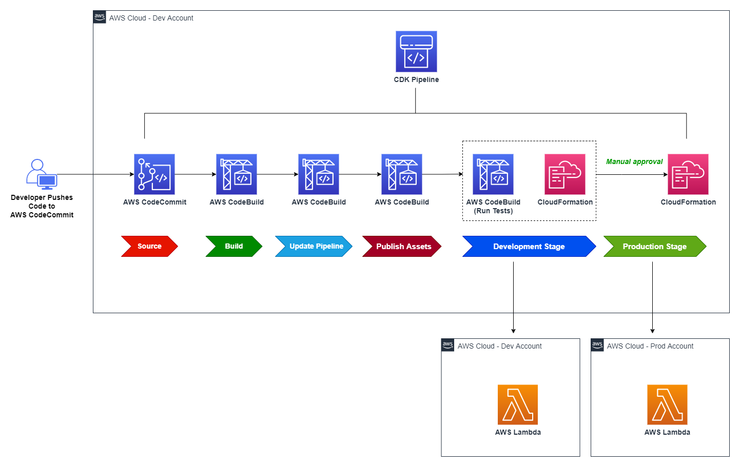
Figure 1: Reference architecture diagram

Figure 1: Reference architecture diagram

The solution creates a CodePipeline with a AWS CodeCommit repo as the source (CodePipeline Source Stage). When code is checked into CodeCommit, the pipeline is automatically triggered and retrieves the code from the CodeCommit repository branch to proceed to the Build stage.

  • Build stage compiles the CDK application code and generates the cloud assembly.
  • Update Pipeline stage updates the pipeline (if necessary).
  • Publish Assets stage uploads the CDK assets to Amazon S3.

After Publish Assets is complete, the pipeline deploys the Lambda function to both the development and production environments. For added control, the architecture includes a manual approval step for releases that target the production environment.

Prerequisites

For this tutorial, you should have:

  1. An AWS account
  2. Visual Studio 2022
  3. AWS Toolkit for Visual Studio
  4. Node.js 18.x or later
  5. AWS CDK v2 (2.67.0 or later required)
  6. Git

Bootstrapping

Before you use AWS CDK to deploy CDK Pipelines, you must bootstrap the AWS environments where you want to deploy the Lambda function. An environment is the target AWS account and Region into which the stack is intended to be deployed.

In this post, you deploy the Lambda function into a development environment and, optionally, a production environment. This requires bootstrapping both environments. However, deployment to a production environment is optional; you can skip bootstrapping that environment for the time being, as we will cover that later.

This is one-time activity per environment for each environment to which you want to deploy CDK applications. To bootstrap the development environment, run the below command, substituting in the AWS account ID for your dev account, the region you will use for your dev environment, and the locally-configured AWS CLI profile you wish to use for that account. See the documentation for additional details.

cdk bootstrap aws://<DEV-ACCOUNT-ID>/<DEV-REGION> \
    --profile DEV-PROFILE \ 
    --cloudformation-execution-policies arn:aws:iam::aws:policy/AdministratorAccess

‐‐profile specifies the AWS CLI credential profile that will be used to bootstrap the environment. If not specified, default profile will be used. The profile should have sufficient permissions to provision the resources for the AWS CDK during bootstrap process.

‐‐cloudformation-execution-policies specifies the ARNs of managed policies that should be attached to the deployment role assumed by AWS CloudFormation during deployment of your stacks.

Note: By default, stacks are deployed with full administrator permissions using the AdministratorAccess policy, but for real-world usage, you should define a more restrictive IAM policy and use that, refer customizing bootstrapping in AWS CDK documentation and Secure CDK deployments with IAM permission boundaries to see how to do that.

Create a Git repository in AWS CodeCommit

For this post, you will use CodeCommit to store your source code. First, create a git repository named dotnet-lambda-cdk-pipeline in CodeCommit by following these steps in the CodeCommit documentation.

After you have created the repository, generate git credentials to access the repository from your local machine if you don’t already have them. Follow the steps below to generate git credentials.

  1. Sign in to the AWS Management Console and open the IAM console.
  2. Create an IAM user (for example, git-user).
  3. Once user is created, attach AWSCodeCommitPowerUser policy to the user.
  4. Next. open the user details page, choose the Security Credentials tab, and in HTTPS Git credentials for AWS CodeCommit, choose Generate.
  5. Download credentials to download this information as a .CSV file.

Clone the recently created repository to your workstation, then cd into dotnet-lambda-cdk-pipeline directory.

git clone <CODECOMMIT-CLONE-URL>
cd dotnet-lambda-cdk-pipeline

Alternatively, you can use git-remote-codecommit to clone the repository with git clone codecommit::<REGION>://<PROFILE>@<REPOSITORY-NAME> command, replacing the placeholders with their original values. Using git-remote-codecommit does not require you to create additional IAM users to manage git credentials. To learn more, refer AWS CodeCommit with git-remote-codecommit documentation page.

Initialize the CDK project

From the command prompt, inside the dotnet-lambda-cdk-pipeline directory, initialize a AWS CDK project by running the following command.

cdk init app --language csharp

Open the generated C# solution in Visual Studio, right-click the DotnetLambdaCdkPipeline project and select Properties. Set the Target framework to .NET 6.

Create a CDK stack to provision the CodePipeline

Your CDK Pipelines application includes at least two stacks: one that represents the pipeline itself, and one or more stacks that represent the application(s) deployed via the pipeline. In this step, you create the first stack that deploys a CodePipeline pipeline in your AWS account.

From Visual Studio, open the solution by opening the .sln solution file (in the src/ folder). Once the solution has loaded, open the DotnetLambdaCdkPipelineStack.cs file, and replace its contents with the following code. Note that the filename, namespace and class name all assume you named your Git repository as shown earlier.

Note: be sure to replace “<CODECOMMIT-REPOSITORY-NAME>” in the code below with the name of your CodeCommit repository (in this blog post, we have used dotnet-lambda-cdk-pipeline).

using Amazon.CDK;
using Amazon.CDK.AWS.CodeBuild;
using Amazon.CDK.AWS.CodeCommit;
using Amazon.CDK.AWS.IAM;
using Amazon.CDK.Pipelines;
using Constructs;
using System.Collections.Generic;

namespace DotnetLambdaCdkPipeline 
{
    public class DotnetLambdaCdkPipelineStack : Stack
    {
        internal DotnetLambdaCdkPipelineStack(Construct scope, string id, IStackProps props = null) : base(scope, id, props)
        {
    
            var repository = Repository.FromRepositoryName(this, "repository", "<CODECOMMIT-REPOSITORY-NAME>");
    
            // This construct creates a pipeline with 3 stages: Source, Build, and UpdatePipeline
            var pipeline = new CodePipeline(this, "pipeline", new CodePipelineProps
            {
                PipelineName = "LambdaPipeline",
                SelfMutation = true,
    
                // Synth represents a build step that produces the CDK Cloud Assembly.
                // The primary output of this step needs to be the cdk.out directory generated by the cdk synth command.
                Synth = new CodeBuildStep("Synth", new CodeBuildStepProps
                {
                    // The files downloaded from the repository will be placed in the working directory when the script is executed
                    Input = CodePipelineSource.CodeCommit(repository, "master"),
    
                    // Commands to run to generate CDK Cloud Assembly
                    Commands = new string[] { "npm install -g aws-cdk", "cdk synth" },
    
                    // Build environment configuration
                    BuildEnvironment = new BuildEnvironment
                    {
                        BuildImage = LinuxBuildImage.AMAZON_LINUX_2_4,
                        ComputeType = ComputeType.MEDIUM,
    
                        // Specify true to get a privileged container inside the build environment image
                        Privileged = true
                    }
                })
            });
        }
    }
}

In the preceding code, you use CodeBuildStep instead of ShellStep, since ShellStep doesn’t provide a property to specify BuildEnvironment. We need to specify the build environment in order to set privileged mode, which allows access to the Docker daemon in order to build container images in the build environment. This is necessary to use the CDK’s bundling feature, which is explained in later in this blog post.

Open the file src/DotnetLambdaCdkPipeline/Program.cs, and edit its contents to reflect the below. Be sure to replace the placeholders with your AWS account ID and region for your dev environment.

using Amazon.CDK;

namespace DotnetLambdaCdkPipeline
{
    sealed class Program
    {
        public static void Main(string[] args)
        {
            var app = new App();
            new DotnetLambdaCdkPipelineStack(app, "DotnetLambdaCdkPipelineStack", new StackProps
            {
                Env = new Amazon.CDK.Environment
                {
                    Account = "<DEV-ACCOUNT-ID>",
                    Region = "<DEV-REGION>"
                }
            });
            app.Synth();
        }
    }
}

Note: Instead of committing the account ID and region to source control, you can set environment variables on the CodeBuild agent and use them; see Environments in the AWS CDK documentation for more information. Because the CodeBuild agent is also configured in your CDK code, you can use the BuildEnvironmentVariableType property to store environment variables in AWS Systems Manager Parameter Store or AWS Secrets Manager.

After you make the code changes, build the solution to ensure there are no build issues. Next, commit and push all the changes you just made. Run the following commands (or alternatively use Visual Studio’s built-in Git functionality to commit and push your changes):

git add --all .
git commit -m 'Initial commit'
git push

Then navigate to the root directory of repository where your cdk.json file is present, and run the cdk deploy command to deploy the initial version of CodePipeline. Note that the deployment can take several minutes.

The pipeline created by CDK Pipelines is self-mutating. This means you only need to run cdk deploy one time to get the pipeline started. After that, the pipeline automatically updates itself if you add new CDK applications or stages in the source code.

After the deployment has finished, a CodePipeline is created and automatically runs. The pipeline includes three stages as shown below.

  • Source – It fetches the source of your AWS CDK app from your CodeCommit repository and triggers the pipeline every time you push new commits to it.
  • Build – This stage compiles your code (if necessary) and performs a cdk synth. The output of that step is a cloud assembly.
  • UpdatePipeline – This stage runs cdk deploy command on the cloud assembly generated in previous stage. It modifies the pipeline if necessary. For example, if you update your code to add a new deployment stage to the pipeline to your application, the pipeline is automatically updated to reflect the changes you made.
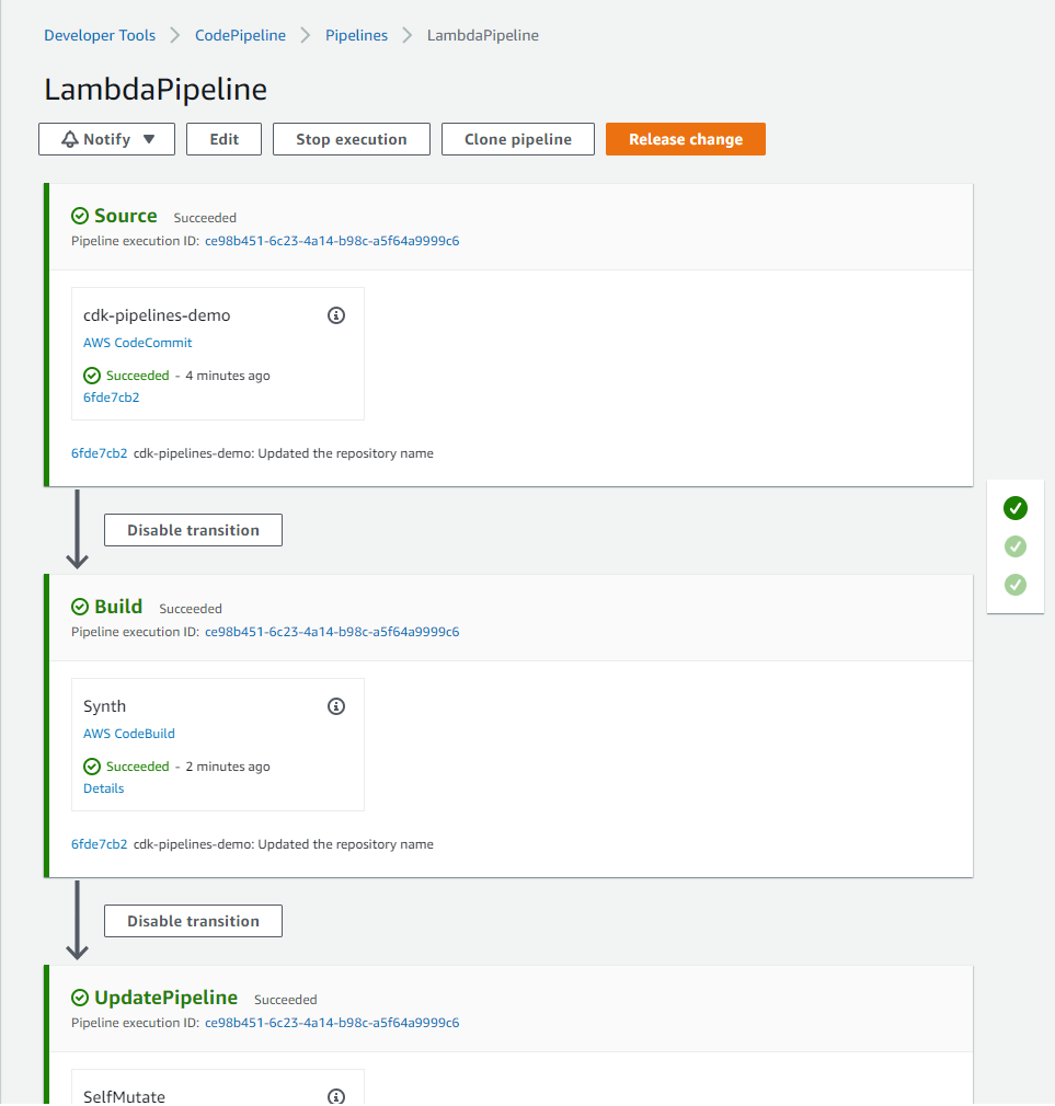
Figure 2: Initial CDK pipeline stages

Figure 2: Initial CDK pipeline stages

Define a CodePipeline stage to deploy .NET Lambda function

In this step, you create a stack containing a simple Lambda function and place that stack in a stage. Then you add the stage to the pipeline so it can be deployed.

To create a Lambda project, do the following:

  1. In Visual Studio, right-click on the solution, choose Add, then choose New Project.
  2. In the New Project dialog box, choose the AWS Lambda Project (.NET Core – C#) template, and then choose OK or Next.
  3. For Project Name, enter SampleLambda, and then choose Create.
  4. From the Select Blueprint dialog, choose Empty Function, then choose Finish.

Next, create a new file in the CDK project at src/DotnetLambdaCdkPipeline/SampleLambdaStack.cs to define your application stack containing a Lambda function. Update the file with the following contents (adjust the namespace as necessary):

using Amazon.CDK;
using Amazon.CDK.AWS.Lambda;
using Constructs;
using AssetOptions = Amazon.CDK.AWS.S3.Assets.AssetOptions;

namespace DotnetLambdaCdkPipeline 
{
    class SampleLambdaStack: Stack
    {
        public SampleLambdaStack(Construct scope, string id, StackProps props = null) : base(scope, id, props)
        {
            // Commands executed in a AWS CDK pipeline to build, package, and extract a .NET function.
            var buildCommands = new[]
            {
                "cd /asset-input",
                "export DOTNET_CLI_HOME=\"/tmp/DOTNET_CLI_HOME\"",
                "export PATH=\"$PATH:/tmp/DOTNET_CLI_HOME/.dotnet/tools\"",
                "dotnet build",
                "dotnet tool install -g Amazon.Lambda.Tools",
                "dotnet lambda package -o output.zip",
                "unzip -o -d /asset-output output.zip"
            };
                
            new Function(this, "LambdaFunction", new FunctionProps
            {
                Runtime = Runtime.DOTNET_6,
                Handler = "SampleLambda::SampleLambda.Function::FunctionHandler",
    
                // Asset path should point to the folder where .csproj file is present.
                // Also, this path should be relative to cdk.json file.
                Code = Code.FromAsset("./src/SampleLambda", new AssetOptions
                {
                    Bundling = new BundlingOptions
                    {
                        Image = Runtime.DOTNET_6.BundlingImage,
                        Command = new[]
                        {
                            "bash", "-c", string.Join(" && ", buildCommands)
                        }
                    }
                })
            });
        }
    }
}

Building inside a Docker container

The preceding code uses bundling feature to build the Lambda function inside a docker container. Bundling starts a new docker container, copies the Lambda source code inside /asset-input directory of the container, runs the specified commands that write the package files under /asset-output directory. The files in /asset-output are copied as assets to the stack’s cloud assembly directory. In a later stage, these files are zipped and uploaded to S3 as the CDK asset.

Building Lambda functions inside Docker containers is preferable than building them locally because it reduces the host machine’s dependencies, resulting in greater consistency and reliability in your build process.

Bundling requires the creation of a docker container on your build machine. For this purpose, the privileged: true setting on the build machine has already been configured.

Adding development stage

Create a new file in the CDK project at src/DotnetLambdaCdkPipeline/DotnetLambdaCdkPipelineStage.cs to hold your stage. This class will create the development stage for your pipeline.

using Amazon.CDK; 
using Constructs; 

namespace DotnetLambdaCdkPipeline
{
    public class DotnetLambdaCdkPipelineStage : Stage
    {
        internal DotnetLambdaCdkPipelineStage(Construct scope, string id, IStageProps props = null) : base(scope, id, props)
        {
            Stack lambdaStack = new SampleLambdaStack(this, "LambdaStack");
        }
    }
}

Edit src/DotnetLambdaCdkPipeline/DotnetLambdaCdkPipelineStack.cs to add the stage to your pipeline. Add the bolded line from the code below to your file.

using Amazon.CDK; 
using Amazon.CDK.Pipelines; 

namespace DotnetLambdaCdkPipeline 
{
    public class DotnetLambdaCdkPipelineStack : Stack
    {
        internal DotnetLambdaCdkPipelineStack(Construct scope, string id, IStackProps props = null) : base(scope, id, props)
        {
    
            var repository = Repository.FromRepositoryName(this, "repository", "dotnet-lambda-cdk-application");
    
            // This construct creates a pipeline with 3 stages: Source, Build, and UpdatePipeline
            var pipeline = new CodePipeline(this, "pipeline", new CodePipelineProps
            {
                PipelineName = "LambdaPipeline",
                .
                .
                .
            });
            
            var devStage = pipeline.AddStage(new DotnetLambdaCdkPipelineStage(this, "Development"));
        }
    }
}

Next, build the solution, then commit and push the changes to the CodeCommit repo. This will trigger the CodePipeline to start.

When the pipeline runs, UpdatePipeline stage detects the changes and updates the pipeline based on the code it finds there. After the UpdatePipeline stage completes, pipeline is updated with additional stages.

Let’s observe the changes:

  1. An Assets stage has been added. This stage uploads all the assets you are using in your app to Amazon S3 (the S3 bucket created during bootstrapping) so that they could be used by other deployment stages later in the pipeline. For example, the CloudFormation template used by the development stage, includes reference to these assets, which is why assets are first moved to S3 and then referenced in later stages.
  2. A Development stage with two actions has been added. The first action is to create the change set, and the second is to execute it.
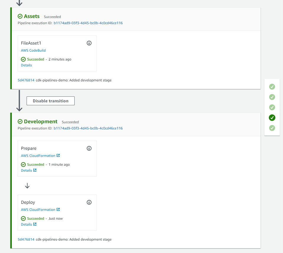
Figure 3: CDK pipeline with development stage to deploy .NET Lambda function

Figure 3: CDK pipeline with development stage to deploy .NET Lambda function

After the Deploy stage has completed, you can find the newly-deployed Lambda function by visiting the Lambda console, selecting “Functions” from the left menu, and filtering the functions list with “LambdaStack”. Note the runtime is .NET.

Running Unit Test cases in the CodePipeline

Next, you will add unit test cases to your Lambda function, and run them through the pipeline to generate a test report in CodeBuild.

To create a Unit Test project, do the following:

  1. Right click on the solution, choose Add, then choose New Project.
  2. In the New Project dialog box, choose the xUnit Test Project template, and then choose OK or Next.
  3. For Project Name, enter SampleLambda.Tests, and then choose Create or Next.
    Depending on your version of Visual Studio, you may be prompted to select the version of .NET to use. Choose .NET 6.0 (Long Term Support), then choose Create.
  4. Right click on SampleLambda.Tests project, choose Add, then choose Project Reference. Select SampleLambda project, and then choose OK.

Next, edit the src/SampleLambda.Tests/UnitTest1.cs file to add a unit test. You can use the code below, which verifies that the Lambda function returns the input string as upper case.

using Xunit;

namespace SampleLambda.Tests
{
    public class UnitTest1
    {
        [Fact]
        public void TestSuccess()
        {
            var lambda = new SampleLambda.Function();

            var result = lambda.FunctionHandler("test string", context: null);

            Assert.Equal("TEST STRING", result);
        }
    }
}

You can add pre-deployment or post-deployment actions to the stage by calling its AddPre() or AddPost() method. To execute above test cases, we will use a pre-deployment action.

To add a pre-deployment action, we will edit the src/DotnetLambdaCdkPipeline/DotnetLambdaCdkPipelineStack.cs file in the CDK project, after we add code to generate test reports.

To run the unit test(s) and publish the test report in CodeBuild, we will construct a BuildSpec for our CodeBuild project. We also provide IAM policy statements to be attached to the CodeBuild service role granting it permissions to run the tests and create reports. Update the file by adding the new code (starting with “// Add this code for test reports”) below the devStage declaration you added earlier:

using Amazon.CDK; 
using Amazon.CDK.Pipelines;
...

namespace DotnetLambdaCdkPipeline 
{
    public class DotnetLambdaCdkPipelineStack : Stack
    {
        internal DotnetLambdaCdkPipelineStack(Construct scope, string id, IStackProps props = null) : base(scope, id, props)
        {
            // ...
            // ...
            // ...
            var devStage = pipeline.AddStage(new DotnetLambdaCdkPipelineStage(this, "Development"));


            // Add this code for test reports
            var reportGroup = new ReportGroup(this, "TestReports", new ReportGroupProps
            {
                ReportGroupName = "TestReports"
            });
           
            // Policy statements for CodeBuild Project Role
            var policyProps = new PolicyStatementProps()
            {
                Actions = new string[] {
                    "codebuild:CreateReportGroup",
                    "codebuild:CreateReport",
                    "codebuild:UpdateReport",
                    "codebuild:BatchPutTestCases"
                },
                Effect = Effect.ALLOW,
                Resources = new string[] { reportGroup.ReportGroupArn }
            };
            
            // PartialBuildSpec in AWS CDK for C# can be created using Dictionary
            var reports = new Dictionary<string, object>()
            {
                {
                    "reports", new Dictionary<string, object>()
                    {
                        {
                            reportGroup.ReportGroupArn, new Dictionary<string,object>()
                            {
                                { "file-format", "VisualStudioTrx" },
                                { "files", "**/*" },
                                { "base-directory", "./testresults" }
                            }
                        }
                    }
                }
            };
            // End of new code block
        }
    }
}

Finally, add the CodeBuildStep as a pre-deployment action to the development stage with necessary CodeBuildStepProps to set up reports. Add this after the new code you added above.

devStage.AddPre(new Step[]
{
    new CodeBuildStep("Unit Test", new CodeBuildStepProps
    {
        Commands= new string[]
        {
            "dotnet test -c Release ./src/SampleLambda.Tests/SampleLambda.Tests.csproj --logger trx --results-directory ./testresults",
        },
        PrimaryOutputDirectory = "./testresults",
        PartialBuildSpec= BuildSpec.FromObject(reports),
        RolePolicyStatements = new PolicyStatement[] { new PolicyStatement(policyProps) },
        BuildEnvironment = new BuildEnvironment
        {
            BuildImage = LinuxBuildImage.AMAZON_LINUX_2_4,
            ComputeType = ComputeType.MEDIUM
        }
    })
});

Build the solution, then commit and push the changes to the repository. Pushing the changes triggers the pipeline, runs the test cases, and publishes the report to the CodeBuild console. To view the report, after the pipeline has completed, navigate to TestReports in CodeBuild’s Report Groups as shown below.
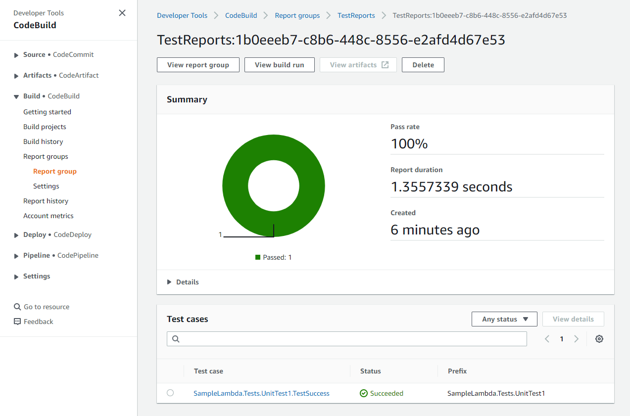
Figure 4: Test report in CodeBuild report group

Figure 4: Test report in CodeBuild report group

Deploying to production environment with manual approval

CDK Pipelines makes it very easy to deploy additional stages with different accounts. You have to bootstrap the accounts and Regions you want to deploy to, and they must have a trust relationship added to the pipeline account.

To bootstrap an additional production environment into which AWS CDK applications will be deployed by the pipeline, run the below command, substituting in the AWS account ID for your production account, the region you will use for your production environment, the AWS CLI profile to use with the prod account, and the AWS account ID where the pipeline is already deployed (the account you bootstrapped at the start of this blog).

cdk bootstrap aws://<PROD-ACCOUNT-ID>/<PROD-REGION>
    --profile <PROD-PROFILE> \
    --cloudformation-execution-policies arn:aws:iam::aws:policy/AdministratorAccess \
    --trust <PIPELINE-ACCOUNT-ID>

The --trust option indicates which other account should have permissions to deploy AWS CDK applications into this environment. For this option, specify the pipeline’s AWS account ID.

Use below code to add a new stage for production deployment with manual approval. Add this code below the “devStage.AddPre(...)” code block you added in the previous section, and remember to replace the placeholders with your AWS account ID and region for your prod environment.

var prodStage = pipeline.AddStage(new DotnetLambdaCdkPipelineStage(this, "Production", new StageProps
{
    Env = new Environment
    {
        Account = "<PROD-ACCOUNT-ID>",
        Region = "<PROD-REGION>"
    }
}), new AddStageOpts
{
    Pre = new[] { new ManualApprovalStep("PromoteToProd") }
});

To support deploying CDK applications to another account, the artifact buckets must be encrypted, so add a CrossAccountKeys property to the CodePipeline near the top of the pipeline stack file, and set the value to true (see the line in bold in the code snippet below). This creates a KMS key for the artifact bucket, allowing cross-account deployments.

var pipeline = new CodePipeline(this, "pipeline", new CodePipelineProps
{
   PipelineName = "LambdaPipeline",
   SelfMutation = true,
   CrossAccountKeys = true,
   EnableKeyRotation = true, //Enable KMS key rotation for the generated KMS keys
   
   // ...
}

After you commit and push the changes to the repository, a new manual approval step called PromoteToProd is added to the Production stage of the pipeline. The pipeline pauses at this step and awaits manual approval as shown in the screenshot below.
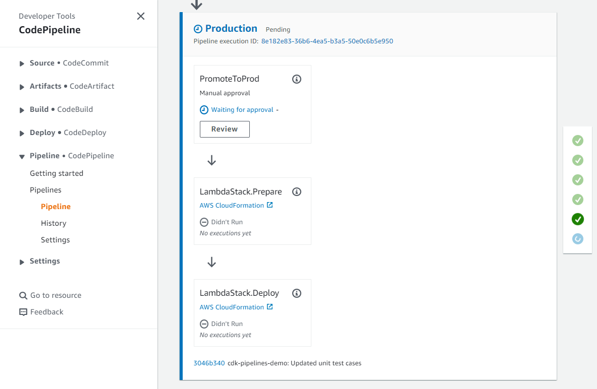
Figure 5: Pipeline waiting for manual review

Figure 5: Pipeline waiting for manual review

When you click the Review button, you are presented with the following dialog. From here, you can choose to approve or reject and add comments if needed.
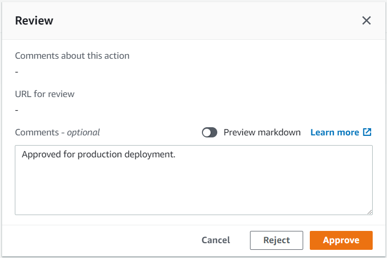
Figure 6: Manual review approval dialog

Figure 6: Manual review approval dialog

Once you approve, the pipeline resumes, executes the remaining steps and completes the deployment to production environment.
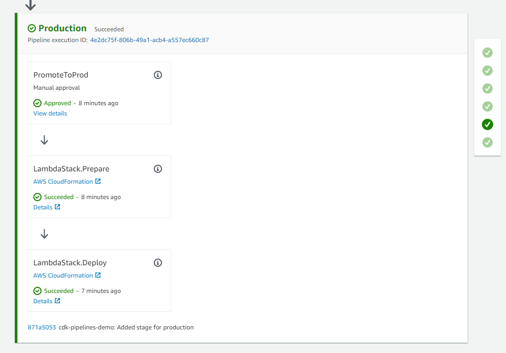
Figure 7: Successful deployment to production environment

Figure 7: Successful deployment to production environment

Clean up

To avoid incurring future charges, log into the AWS console of the different accounts you used, go to the AWS CloudFormation console of the Region(s) where you chose to deploy, select and click Delete on the stacks created for this activity. Alternatively, you can delete the CloudFormation Stack(s) using cdk destroy command. It will not delete the CDKToolkit stack that the bootstrap command created. If you want to delete that as well, you can do it from the AWS Console.

Conclusion

In this post, you learned how to use CDK Pipelines for automating the deployment process of .NET Lambda functions. An intuitive and flexible architecture makes it easy to set up a CI/CD pipeline that covers the entire application lifecycle, from build and test to deployment. With CDK Pipelines, you can streamline your development workflow, reduce errors, and ensure consistent and reliable deployments.
For more information on CDK Pipelines and all the ways it can be used, see the CDK Pipelines reference documentation.

About the authors:

Ankush Jain

Ankush Jain

Ankush Jain is a Cloud Consultant at AWS Professional Services based out of Pune, India. He currently focuses on helping customers migrate their .NET applications to AWS. He is passionate about cloud, with a keen interest in serverless technologies.

Sanjay Chaudhari

Sanjay Chaudhari

Sanjay Chaudhari is a Cloud Consultant with AWS Professional Services. He works with customers to migrate and modernize their Microsoft workloads to the AWS Cloud.

Simplify and speed up Apache Spark applications on Amazon Redshift data with Amazon Redshift integration for Apache Spark

Post Syndicated from Gagan Brahmi original https://aws.amazon.com/blogs/big-data/simplify-and-speed-up-apache-spark-applications-on-amazon-redshift-data-with-amazon-redshift-integration-for-apache-spark/

Customers use Amazon Redshift to run their business-critical analytics on petabytes of structured and semi-structured data. Apache Spark is a popular framework that you can use to build applications for use cases such as ETL (extract, transform, and load), interactive analytics, and machine learning (ML). Apache Spark enables you to build applications in a variety of languages, such as Java, Scala, and Python, by accessing the data in your Amazon Redshift data warehouse.

Amazon Redshift integration for Apache Spark helps developers seamlessly build and run Apache Spark applications on Amazon Redshift data. Developers can use AWS analytics and ML services such as Amazon EMR, AWS Glue, and Amazon SageMaker to effortlessly build Apache Spark applications that read from and write to their Amazon Redshift data warehouse. You can do so without compromising on the performance of your applications or transactional consistency of your data.

In this post, we discuss why Amazon Redshift integration for Apache Spark is critical and efficient for analytics and ML. In addition, we discuss use cases that use Amazon Redshift integration with Apache Spark to drive business impact. Finally, we walk you through step-by-step examples of how to use this official AWS connector in an Apache Spark application.

Amazon Redshift integration for Apache Spark

The Amazon Redshift integration for Apache Spark minimizes the cumbersome and often manual process of setting up a spark-redshift connector (community version) and shortens the time needed to prepare for analytics and ML tasks. You only need to specify the connection to your data warehouse, and you can start working with Amazon Redshift data from your Apache Spark-based applications within minutes.

You can use several pushdown capabilities for operations such as sort, aggregate, limit, join, and scalar functions so that only the relevant data is moved from your Amazon Redshift data warehouse to the consuming Apache Spark application. This allows you to improve the performance of your applications. Amazon Redshift admins can easily identify the SQL generated from Spark-based applications. In this post, we show how you can find out the SQL generated by the Apache Spark job.

Moreover, Amazon Redshift integration for Apache Spark uses Parquet file format when staging the data in a temporary directory. Amazon Redshift uses the UNLOAD SQL statement to store this temporary data on Amazon Simple Storage Service (Amazon S3). The Apache Spark application retrieves the results from the temporary directory (stored in Parquet file format), which improves performance.

You can also help make your applications more secure by utilizing AWS Identity and Access Management (IAM) credentials to connect to Amazon Redshift.

Amazon Redshift integration for Apache Spark is built on top of the spark-redshift connector (community version) and enhances it for performance and security, helping you gain up to 10 times faster application performance.

Use cases for Amazon Redshift integration with Apache Spark

For our use case, the leadership of the product-based company wants to know the sales for each product across multiple markets. As sales for the company fluctuate dynamically, it has become a challenge for the leadership to track the sales across multiple markets. However, the overall sales are declining, and the company leadership wants to find out which markets aren’t performing so that they can target these markets for promotion campaigns.

For sales across multiple markets, the product sales data such as orders, transactions, and shipment data is available on Amazon S3 in the data lake. The data engineering team can use Apache Spark with Amazon EMR or AWS Glue to analyze this data in Amazon S3.

The inventory data is available in Amazon Redshift. Similarly, the data engineering team can analyze this data with Apache Spark using Amazon EMR or an AWS Glue job by using the Amazon Redshift integration for Apache Spark to perform aggregations and transformations. The aggregated and transformed dataset can be stored back into Amazon Redshift using the Amazon Redshift integration for Apache Spark.

Using a distributed framework like Apache Spark with the Amazon Redshift integration for Apache Spark can provide the visibility across the data lake and data warehouse to generate sales insights. These insights can be made available to the business stakeholders and line of business users in Amazon Redshift to make informed decisions to run targeted promotions for the low revenue market segments.

Additionally, we can use the Amazon Redshift integration with Apache Spark in the following use cases:

  • An Amazon EMR or AWS Glue customer running Apache Spark jobs wants to transform data and write that into Amazon Redshift as a part of their ETL pipeline
  • An ML customer uses Apache Spark with SageMaker for feature engineering for accessing and transforming data in Amazon Redshift
  • An Amazon EMR, AWS Glue, or SageMaker customer uses Apache Spark for interactive data analysis with data on Amazon Redshift from notebooks

Examples for Amazon Redshift integration for Apache Spark in an Apache Spark application

In this post, we show the steps to connect Amazon Redshift from Amazon EMR on Amazon Elastic Compute Cloud (Amazon EC2), Amazon EMR Serverless, and AWS Glue using a common script. In the following sample code, we generate a report showing the quarterly sales for the year 2008. To do that, we join two Amazon Redshift tables using an Apache Spark DataFrame, run a predicate pushdown, aggregate and sort the data, and write the transformed data back to Amazon Redshift. The script uses PySpark

The script uses IAM-based authentication for Amazon Redshift. IAM roles used by Amazon EMR and AWS Glue should have the appropriate permissions to authenticate Amazon Redshift, and access to an S3 bucket for temporary data storage.

The following example policy allows the IAM role to call the GetClusterCredentials operations:

{
  "Version": "2012-10-17",
  "Statement": {
    "Effect": "Allow",
    "Action": "redshift:GetClusterCredentials",
    "Resource": "arn:aws:redshift:<aws_region_name>:xxxxxxxxxxxx:dbuser:*/temp_*"
  }
}

The following example policy allows access to an S3 bucket for temporary data storage:

{
    "Version": "2012-10-17",
    "Statement": [
        {
            "Sid": "VisualEditor0",
            "Effect": "Allow",
            "Action": [
                "s3:PutObject",
                "s3:GetObject",
                "s3:ListBucket"
            ],
            "Resource": "arn:aws:s3:::<s3_bucket_name>"
        }
    ]
}

The complete script is as follows:

from pyspark.sql import SparkSession
from pyspark.sql.functions import col

# Initiate Apache Spark session
spark = SparkSession \
        .builder \
        .appName("SparkRedshiftConnector") \
        .enableHiveSupport() \
        .getOrCreate()

# Set connection options for Amazon Redshift
jdbc_iam_url = "jdbc:redshift:iam://redshift-spark-connector-1.xxxxxxxxxxx.<aws_region_name>.redshift.amazonaws.com:5439/sample_data_dev"
temp_dir = 's3://<s3_bucket_name>/redshift-temp-dir/'
aws_role = 'arn:aws:iam::xxxxxxxxxxxx:role/redshift-s3'

# Set query group for the query. More details on Amazon Redshift WLM https://docs.aws.amazon.com/redshift/latest/dg/cm-c-executing-queries.html
queryGroup = "emr-redshift"
jdbc_iam_url_withQueryGroup = jdbc_iam_url+'?queryGroup='+queryGroup

# Set User name for the query
userName = 'awsuser'
jdbc_iam_url_withUserName = jdbc_iam_url_withQueryGroup+';user='+userName

# Define the Amazon Redshift context
redshiftOptions = {
    "url": jdbc_iam_url_withUserName,
    "tempdir": temp_dir,
    "aws_iam_role" : aws_role
}

# Create the sales DataFrame from Amazon Redshift table using io.github.spark_redshift_community.spark.redshift class
sales_df = (
    spark.read
        .format("io.github.spark_redshift_community.spark.redshift")
        .options(**redshiftOptions)
        .option("dbtable", "tickit.sales")
        .load()
)

# Create the date Data Frame from Amazon Redshift table
date_df = (
    spark.read
        .format("io.github.spark_redshift_community.spark.redshift")
        .options(**redshiftOptions)
        .option("dbtable", "tickit.date")
        .load()
)

# Assign a Data Frame to the above output which will be written back to Amazon Redshift
output_df= sales_df.join(date_df, sales_df.dateid == date_df.dateid, 'inner').where(
    col("year") == 2008).groupBy("qtr").sum("qtysold").select(
        col("qtr"), col("sum(qtysold)")).sort(["qtr"], ascending=[1]).withColumnRenamed("sum(qtysold)","total_quantity_sold")

# Display the output
output_df.show()

## Lets drop the queryGroup for easy validation of push down queries
# Set User name for the query
userName = 'awsuser'
jdbc_iam_url_withUserName = jdbc_iam_url+'?user='+userName

# Define the Amazon Redshift context
redshiftWriteOptions = {
    "url": jdbc_iam_url_withUserName,
    "tempdir": temp_dir,
    "aws_iam_role" : aws_role
}

# Write the Data Frame back to Amazon Redshift
output_df.write \
    .format("io.github.spark_redshift_community.spark.redshift") \
    .mode("overwrite") \
    .options(**redshiftWriteOptions) \
    .option("dbtable", "tickit.test") \
    .save()

If you plan to use the preceding script in your environment, make sure you replace the values for the following variables with the appropriate values for your environment: jdbc_iam_url, temp_dir, and aws_role.

In the next section, we walk through the steps to run this script to aggregate a sample dataset that is made available in Amazon Redshift.

Prerequisites

Before we begin, make sure the following prerequisites are met:

Deploy resources using AWS CloudFormation

Complete the following steps to deploy the CloudFormation stack:

  1. Sign in to the AWS Management Console, then launch the CloudFormation stack:
    BDB-2063-launch-cloudformation-stack

You can also download the CloudFormation template to create the resources mentioned in this post through infrastructure as code (IaC). Use this template when launching a new CloudFormation stack.

  1. Scroll down to the bottom of the page to select I acknowledge that AWS CloudFormation might create IAM resources under Capabilities, then choose Create stack.

The stack creation process takes 15–20 minutes to complete. The CloudFormation template creates the following resources:

    • An Amazon VPC with the needed subnets, route tables, and NAT gateway
    • An S3 bucket with the name redshift-spark-databucket-xxxxxxx (note that xxxxxxx is a random string to make the bucket name unique)
    • An Amazon Redshift cluster with sample data loaded inside the database dev and the primary user redshiftmasteruser. For the purpose of this blog post, redshiftmasteruser with administrative permissions is used. However, it is recommended to use a user with fine grained access control in production environment.
    • An IAM role to be used for Amazon Redshift with the ability to request temporary credentials from the Amazon Redshift cluster’s dev database
    • Amazon EMR Studio with the needed IAM roles
    • Amazon EMR release version 6.9.0 on an EC2 cluster with the needed IAM roles
    • An Amazon EMR Serverless application release version 6.9.0
    • An AWS Glue connection and AWS Glue job version 4.0
    • A Jupyter notebook to run using Amazon EMR Studio using Amazon EMR on an EC2 cluster
    • A PySpark script to run using Amazon EMR Studio and Amazon EMR Serverless
  1. After the stack creation is complete, choose the stack name redshift-spark and navigate to the Outputs

We utilize these output values later in this post.

In the next sections, we show the steps for Amazon Redshift integration for Apache Spark from Amazon EMR on Amazon EC2, Amazon EMR Serverless, and AWS Glue.

Use Amazon Redshift integration with Apache Spark on Amazon EMR on EC2

Starting from Amazon EMR release version 6.9.0 and above, the connector using Amazon Redshift integration for Apache Spark and Amazon Redshift JDBC driver are available locally on Amazon EMR. These files are located under the /usr/share/aws/redshift/ directory. However, in the previous versions of Amazon EMR, the community version of the spark-redshift connector is available.

The following example shows how to connect Amazon Redshift using a PySpark kernel via an Amazon EMR Studio notebook. The CloudFormation stack created Amazon EMR Studio, Amazon EMR on an EC2 cluster, and a Jupyter notebook available to run. To go through this example, complete the following steps:

  1. Download the Jupyter notebook made available in the S3 bucket for you:
    • In the CloudFormation stack outputs, look for the value for EMRStudioNotebook, which should point to the redshift-spark-emr.ipynb notebook available in the S3 bucket.
    • Choose the link or open the link in a new tab by copying the URL for the notebook.
    • After you open the link, download the notebook by choosing Download, which will save the file locally on your computer.
  1. Access Amazon EMR Studio by choosing or copying the link provided in the CloudFormation stack outputs for the key EMRStudioURL.
  2. In the navigation pane, choose Workspaces.
  3. Choose Create Workspace.
  4. Provide a name for the Workspace, for instance redshift-spark.
  5. Expand the Advanced configuration section and select Attach Workspace to an EMR cluster.
  6. Under Attach to an EMR cluster, choose the EMR cluster with the name emrCluster-Redshift-Spark.
  7. Choose Create Workspace.
  8. After the Amazon EMR Studio Workspace is created and in Attached status, you can access the Workspace by choosing the name of the Workspace.

This should open the Workspace in a new tab. Note that if you have a pop-up blocker, you may have to allow the Workspace to open or disable the pop-up blocker.

In the Amazon EMR Studio Workspace, we now upload the Jupyter notebook we downloaded earlier.

  1. Choose Upload to browse your local file system and upload the Jupyter notebook (redshift-spark-emr.ipynb).
  2. Choose (double-click) the redshift-spark-emr.ipynb notebook within the Workspace to open the notebook.

The notebook provides the details of different tasks that it performs. Note that in the section Define the variables to connect to Amazon Redshift cluster, you don’t need to update the values for jdbc_iam_url, temp_dir, and aws_role because these are updated for you by AWS CloudFormation. AWS CloudFormation has also performed the steps mentioned in the Prerequisites section of the notebook.

You can now start running the notebook.

  1. Run the individual cells by selecting them and then choosing Play.

You can also use the key combination of Shift+Enter or Shift+Return. Alternatively, you can run all the cells by choosing Run All Cells on the Run menu.

  1. Find the predicate pushdown operation performed on the Amazon Redshift cluster by the Amazon Redshift integration for Apache Spark.

We can also see the temporary data stored on Amazon S3 in the optimized Parquet format. The output can be seen from running the cell in the section Get the last query executed on Amazon Redshift.

  1. To validate the table created by the job from Amazon EMR on Amazon EC2, navigate to the Amazon Redshift console and choose the cluster redshift-spark-redshift-cluster on the Provisioned clusters dashboard page.
  2. In the cluster details, on the Query data menu, choose Query in query editor v2.
  3. Choose the cluster in the navigation pane and connect to the Amazon Redshift cluster when it requests for authentication.
  4. Select Temporary credentials.
  5. For Database, enter dev.
  6. For User name, enter redshiftmasteruser.
  7. Choose Save.
  8. In the navigation pane, expand the cluster redshift-spark-redshift-cluster, expand the dev database, expand tickit, and expand Tables to list all the tables inside the schema tickit.

You should find the table test_emr.

  1. Choose (right-click) the table test_emr, then choose Select table to query the table.
  2. Choose Run to run the SQL statement.

Use Amazon Redshift integration with Apache Spark on Amazon EMR Serverless

The Amazon EMR release version 6.9.0 and above provides the Amazon Redshift integration for Apache Spark JARs (managed by Amazon Redshift) and Amazon Redshift JDBC JARs locally on Amazon EMR Serverless as well. These files are located under the /usr/share/aws/redshift/ directory. In the following example, we use the Python script made available in the S3 bucket by the CloudFormation stack we created earlier.

  1. In the CloudFormation stack outputs, make a note of the value for EMRServerlessExecutionScript, which is the location of the Python script in the S3 bucket.
  2. Also note the value for EMRServerlessJobExecutionRole, which is the IAM role to be used with running the Amazon EMR Serverless job.
  3. Access Amazon EMR Studio by choosing or copying the link provided in the CloudFormation stack outputs for the key EMRStudioURL.
  4. Choose Applications under Serverless in the navigation pane.

You will find an EMR application created by the CloudFormation stack with the name emr-spark-redshift.

  1. Choose the application name to submit a job.
  2. Choose Submit job.
  3. Under Job details, for Name, enter an identifiable name for the job.
  4. For Runtime role, choose the IAM role that you noted from the CloudFormation stack output earlier.
  5. For Script location, provide the path to the Python script you noted earlier from the CloudFormation stack output.
  6. Expand the section Spark properties and choose the Edit in text
  7. Enter the following value in the text box, which provides the path to the redshift-connector, Amazon Redshift JDBC driver, spark-avro JAR, and minimal-json JAR files:
    --jars /usr/share/aws/redshift/jdbc/RedshiftJDBC.jar,/usr/share/aws/redshift/spark-redshift/lib/spark-redshift.jar,/usr/share/aws/redshift/spark-redshift/lib/spark-avro.jar,/usr/share/aws/redshift/spark-redshift/lib/minimal-json.jar

  8. Choose Submit job.
  9. Wait for the job to complete and the run status to show as Success.
  10. Navigate to the Amazon Redshift query editor to view if the table was created successfully.
  11. Check the pushdown queries run for Amazon Redshift query group emr-serverless-redshift. You can run the following SQL statement against the database dev:
    SELECT query_text FROM SYS_QUERY_HISTORY WHERE query_label = 'emr-serverless-redshift' ORDER BY start_time DESC LIMIT 1

You can see that the pushdown query and return results are stored in Parquet file format on Amazon S3.

Use Amazon Redshift integration with Apache Spark on AWS Glue

Starting with AWS Glue version 4.0 and above, the Apache Spark jobs connecting to Amazon Redshift can use the Amazon Redshift integration for Apache Spark and Amazon Redshift JDBC driver. Existing AWS Glue jobs that already use Amazon Redshift as source or target can be upgraded to AWS Glue 4.0 to take advantage of this new connector. The CloudFormation template provided with this post creates the following AWS Glue resources:

  • AWS Glue connection for Amazon Redshift – The connection to establish connection from AWS Glue to Amazon Redshift using the Amazon Redshift integration for Apache Spark
  • IAM role attached to the AWS Glue job – The IAM role to manage permissions to run the AWS Glue job
  • AWS Glue job – The script for the AWS Glue job performing transformations and aggregations using the Amazon Redshift integration for Apache Spark

The following example uses the AWS Glue connection attached to the AWS Glue job with PySpark and includes the following steps:

  1. On the AWS Glue console, choose Connections in the navigation pane.
  2. Under Connections, choose the AWS Glue connection for Amazon Redshift created by the CloudFormation template.
  3. Verify the connection details.

You can now reuse this connection within a job or across multiple jobs.

  1. On the Connectors page, choose the AWS Glue job created by the CloudFormation stack under Your jobs, or access the AWS Glue job by using the URL provided for the key GlueJob in the CloudFormation stack output.
  2. Access and verify the script for the AWS Glue job.
  3. On the Job details tab, make sure that Glue version is set to Glue 4.0.

This ensures that the job uses the latest redshift-spark connector.

  1. Expand Advanced properties and in the Connections section, verify that the connection created by the CloudFormation stack is attached.
  2. Verify the job parameters added for the AWS Glue job. These values are also available in the output for the CloudFormation stack.
  3. Choose Save and then Run.

You can view the status for the job run on the Run tab.

  1. After the job run completes successfully, you can verify the output of the table test-glue created by the AWS Glue job.
  2. We check the pushdown queries run for Amazon Redshift query group glue-redshift. You can run the following SQL statement against the database dev:
    SELECT query_text FROM SYS_QUERY_HISTORY WHERE query_label = 'glue-redshift' ORDER BY start_time DESC LIMIT 1

Best practices

Keep in mind the following best practices:

  • Consider using the Amazon Redshift integration for Apache Spark from Amazon EMR instead of using the redshift-spark connector (community version) for your new Apache Spark jobs.
  • If you have existing Apache Spark jobs using the redshift-spark connector (community version), consider upgrading them to use the Amazon Redshift integration for Apache Spark
  • The Amazon Redshift integration for Apache Spark automatically applies predicate and query pushdown to optimize for performance. We recommend using supported functions (autopushdown) in your query. The Amazon Redshift integration for Apache Spark will turn the function into a SQL query and run the query in Amazon Redshift. This optimization results in required data being retrieved, so Apache Spark can process less data and have better performance.
    • Consider using aggregate pushdown functions like avg, count, max, min, and sum to retrieve filtered data for data processing.
    • Consider using Boolean pushdown operators like in, isnull, isnotnull, contains, endswith, and startswith to retrieve filtered data for data processing.
    • Consider using logical pushdown operators like and, or, and not (or !) to retrieve filtered data for data processing.
  • It’s recommended to pass an IAM role using the parameter aws_iam_role for the Amazon Redshift authentication from your Apache Spark application on Amazon EMR or AWS Glue. The IAM role should have necessary permissions to retrieve temporary IAM credentials to authenticate to Amazon Redshift as shown in this blog’s “Examples for Amazon Redshift integration for Apache Spark in an Apache Spark application” section.
  • With this feature, you don’t have to maintain your Amazon Redshift user name and password in the secrets manager and Amazon Redshift database.
  • Amazon Redshift uses the UNLOAD SQL statement to store this temporary data on Amazon S3. The Apache Spark application retrieves the results from the temporary directory (stored in Parquet file format). This temporary directory on Amazon S3 is not cleaned up automatically, and therefore could add additional cost. We recommend using Amazon S3 lifecycle policies to define the retention rules for the S3 bucket.
  • It’s recommended to turn on Amazon Redshift audit logging to log the information about connections and user activities in your database.
  • It’s recommended to turn on Amazon Redshift at-rest encryption to encrypt your data as Amazon Redshift writes it in its data centers and decrypt it for you when you access it.
  • It’s recommended to upgrade to AWS Glue v4.0 and above to use the Amazon Redshift integration for Apache Spark, which is available out of the box. Upgrading to this version of AWS Glue will automatically make use of this feature.
  • It’s recommended to upgrade to Amazon EMR v6.9.0 and above to use the Amazon Redshift integration for Apache Spark. You don’t have to manage any drivers or JAR files explicitly.
  • Consider using Amazon EMR Studio notebooks to interact with your Amazon Redshift data in your Apache Spark application.
  • Consider using AWS Glue Studio to create Apache Spark jobs using a visual interface. You can also switch to writing Apache Spark code in either Scala or PySpark within AWS Glue Studio.

Clean up

Complete the following steps to clean up the resources that are created as a part of the CloudFormation template to ensure that you’re not billed for the resources if you’ll no longer be using them:

  1. Stop the Amazon EMR Serverless application:
    • Access Amazon EMR Studio by choosing or copying the link provided in the CloudFormation stack outputs for the key EMRStudioURL.
    • Choose Applications under Serverless in the navigation pane.

You will find an EMR application created by the CloudFormation stack with the name emr-spark-redshift.

    • If the application status shows as Stopped, you can move to the next steps. However, if the application status is Started, choose the application name, then choose Stop application and Stop application again to confirm.
  1. Delete the Amazon EMR Studio Workspace:
    • Access Amazon EMR Studio by choosing or copying the link provided in the CloudFormation stack outputs for the key EMRStudioURL.
    • Choose Workspaces in the navigation pane.
    • Select the Workspace that you created and choose Delete, then choose Delete again to confirm.
  2. Delete the CloudFormation stack:
    • On the AWS CloudFormation console, navigate to the stack you created earlier.
    • Choose the stack name and then choose Delete to remove the stack and delete the resources created as a part of this post.
    • On the confirmation screen, choose Delete stack.

Conclusion

In this post, we explained how you can use the Amazon Redshift integration for Apache Spark to build and deploy applications with Amazon EMR on Amazon EC2, Amazon EMR Serverless, and AWS Glue to automatically apply predicate and query pushdown to optimize the query performance for data in Amazon Redshift. It’s highly recommended to use Amazon Redshift integration for Apache Spark for seamless and secure connection to Amazon Redshift from your Amazon EMR or AWS Glue.

Here is what some of our customers have to say about the Amazon Redshift integration for Apache Spark:

“We empower our engineers to build their data pipelines and applications with Apache Spark using Python and Scala. We wanted a tailored solution that simplified operations and delivered faster and more efficiently for our clients, and that’s what we get with the new Amazon Redshift integration for Apache Spark.”

—Huron Consulting

“GE Aerospace uses AWS analytics and Amazon Redshift to enable critical business insights that drive important business decisions. With the support for auto-copy from Amazon S3, we can build simpler data pipelines to move data from Amazon S3 to Amazon Redshift. This accelerates our data product teams’ ability to access data and deliver insights to end-users. We spend more time adding value through data and less time on integrations.”

—GE Aerospace

“Our focus is on providing self-service access to data for all of our users at Goldman Sachs. Through Legend, our open-source data management and governance platform, we enable users to develop data-centric applications and derive data-driven insights as we collaborate across the financial services industry. With the Amazon Redshift integration for Apache Spark, our data platform team will be able to access Amazon Redshift data with minimal manual steps, allowing for zero-code ETL that will increase our ability to make it easier for engineers to focus on perfecting their workflow as they collect complete and timely information. We expect to see a performance improvement of applications and improved security as our users can now easily access the latest data in Amazon Redshift.”

—Goldman Sachs


About the Authors

Gagan Brahmi is a Senior Specialist Solutions Architect focused on big data analytics and AI/ML platform at Amazon Web Services. Gagan has over 18 years of experience in information technology. He helps customers architect and build highly scalable, performant, and secure cloud-based solutions on AWS. In his spare time, he spends time with his family and explores new places.

Vivek Gautam is a Data Architect with specialization in data lakes at AWS Professional Services. He works with enterprise customers building data products, analytics platforms, and solutions on AWS. When not building and designing data lakes, Vivek is a food enthusiast who also likes to explore new travel destinations and go on hikes.

Naresh Gautam is a Data Analytics and AI/ML leader at AWS with 20 years of experience, who enjoys helping customers architect highly available, high-performance, and cost-effective data analytics and AI/ML solutions to empower customers with data-driven decision-making. In his free time, he enjoys meditation and cooking.

Beaux Sharifi is a Software Development Engineer within the Amazon Redshift drivers’ team where he leads the development of the Amazon Redshift Integration with Apache Spark connector. He has over 20 years of experience building data-driven platforms across multiple industries. In his spare time, he enjoys spending time with his family and surfing.

Automate discovery of data relationships using ML and Amazon Neptune graph technology

Post Syndicated from Moira Lennox original https://aws.amazon.com/blogs/big-data/automate-discovery-of-data-relationships-using-ml-and-amazon-neptune-graph-technology/

Data mesh is a new approach to data management. Companies across industries are using a data mesh to decentralize data management to improve data agility and get value from data. However, when a data producer shares data products on a data mesh self-serve web portal, it’s neither intuitive nor easy for a data consumer to know which data products they can join to create new insights. This is especially true in a large enterprise with thousands of data products.

This post shows how to use machine learning (ML) and Amazon Neptune to create automated recommendations to join data products and display those recommendations alongside the existing data products. This allows data consumers to easily identify new datasets and provides agility and innovation without spending hours doing analysis and research.

Background

The success of a data-driven organization recognizes data as a key enabler to increase and sustain innovation. It follows what is called a distributed system architecture. The goal of a data product is to solve the long-standing issue of data silos and data quality. Independent data products often only have value if you can connect them, join them, and correlate them to create a higher order data product that creates additional insights. A modern data architecture is critical in order to become a data-driven organization. It allows stakeholders to manage and work with data products across the organization, enhancing the pace and scale of innovation.

Solution overview

A data mesh architecture starts to solve for the decoupled architecture by decoupling the data infrastructure from the application infrastructure, which is a common challenge in traditional data architectures. It focuses on decentralized ownership, domain design, data products, and self-serve data infrastructure. This allows for a new way of thinking and new organizational elements—namely, a modern data community.

However, today’s data mesh platform contains largely independent data products. Even with well-documented data products, knowing how to connect or join data products is a time-consuming job. Data consumers spend hours, days, or months to understand and analyze the data. Identifying links or relationships between data products is critical to create value from the data mesh and enable a data-driven organization.

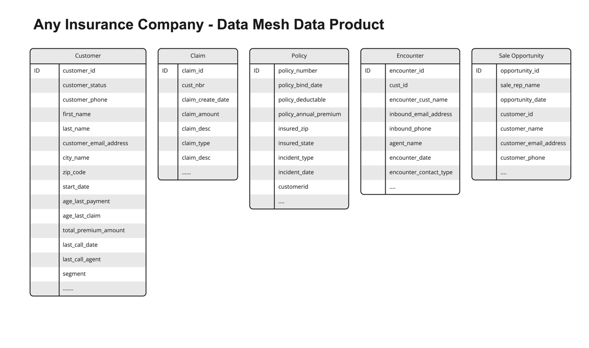
The solution in this post illustrates an approach to solving these challenges. It uses a fictional insurance company with several data products shared on their data mesh marketplace. The following figure shows the sample data products used in our solution.

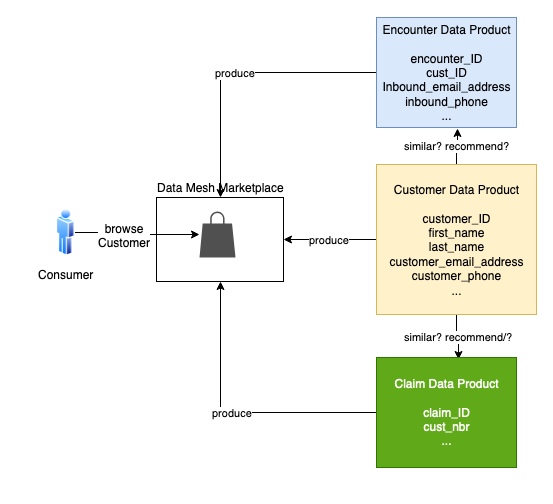
Suppose a consumer is browsing the customer data product in the data mesh marketplace. The consumer wonders if the customer data could be linked to claim, policy, or encounter data. Because these data products come from different lines of business (LOBs) or silos, it’s hard to know. A consumer would have to review each data product and do the necessary analysis and research to know this with any certainty.

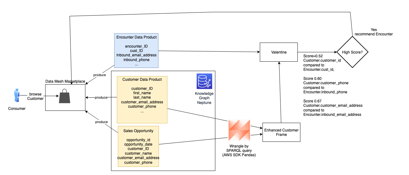
To solve this problem, our solution uses ML and Neptune to create recommendations for the data consumer. The solution generates a list of data products, product attributes, and the associated probability scores to show join ability. This reduces the time to discover, analyze, and create new insights.

We use Valentine, a data science algorithm for comparing datasets, to improve data product recommendations. Neptune, the managed AWS graph database service, stores information about explicit connections between datasets, improving the recommendations.

Example use case

Let’s walk through a concrete example. Suppose a consumer is browsing the Customer data product in the data mesh marketplace. Customer is similar to the Policy and Encounter data products, but these products come from different silos. Their similarity to the Customer is hard to gauge. To expedite the consumer’s work, the mesh recommends how the Policy and Encounter products can be connected to the Customer product.

Let’s consider two cases. First, is Customer similar to Claim? The following is a sample of the data in each product.

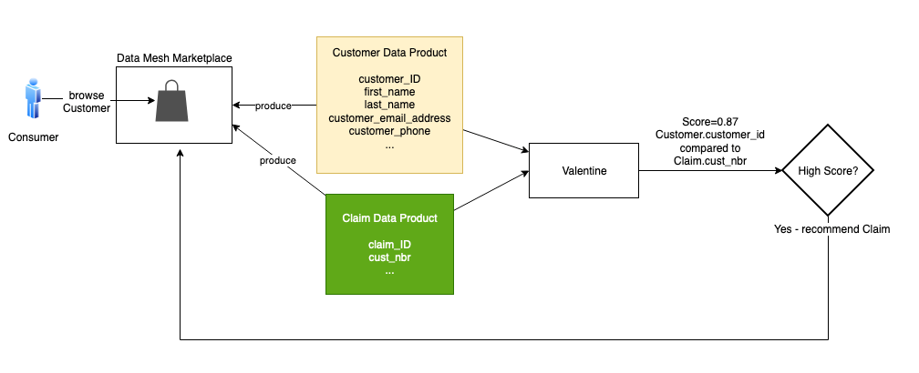
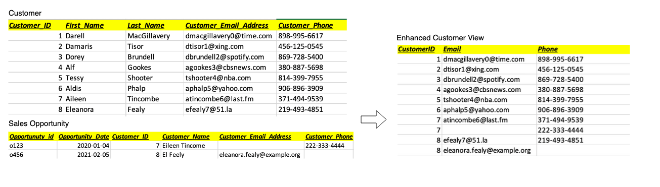
Intuitively, these two products have lots of overlap. Every Cust_Nbr in Claim has a corresponding Customer_ID in Customer. There is no foreign key constraint in Claim that assures us it points to Customer. We think there is enough similarity to infer a join relationship.

The data science algorithm Valentine is an effective tool for this. Valentine is presented in the paper Valentine: Evaluating Matching Techniques for Dataset Discovery (2021, Koutras et al.). Valentine determines if two datasets are joinable or unionable. We focus on the former. Two datasets are joinable if a record from one dataset has a link to a record in the other dataset using one or more columns. Valentine addresses the use case where data is messy: there is no foreign key constraint in place, and data doesn’t match perfectly between datasets. Valentine looks for similarities, and its findings are probabilistic. It scores its proposed matches.

This solution uses an implementation of Valentine available in the following GitHub repo. The first step is to load each data product from its source into a Pandas data frame. If the data is large, load a representative subset of it, at most a few million records. Pass the frames to the valentine_match() function and select the matching method. We use COMA, one of several methods that Valentine supports. The function’s result indicates the similarity of columns and the score. In this case, it tells us that the Customer_ID for Customer matches the Cust_Nbr for Claim, with a very high score. We then instruct the data mesh to recommend Claim to the consumer browsing Customer.

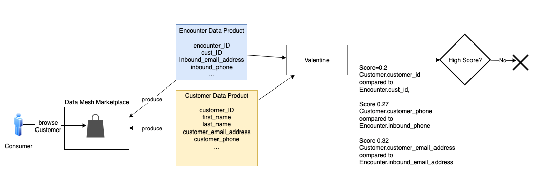
A graph database isn’t required to recommend Claim; the two products could be directly compared. But let’s consider Encounter. Is Customer similar to Encounter? This case is more complicated. Many encounters in the Encounter product don’t link to a customer. An encounter occurs when someone contacts the contact center, which could be by phone or email. The party may or may not be a customer, and if they are a customer, we may not know their customer ID during this encounter. Additionally, sometimes the phone or email they use isn’t the same as the one from a customer record in the Customer product.

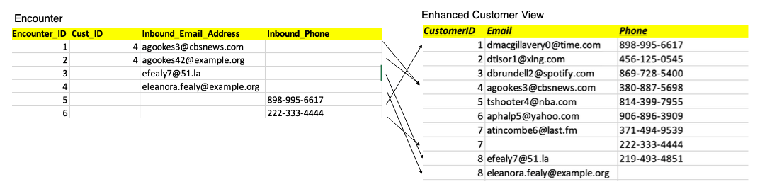
In the following sample encounter set, encounters 1 and 2 match to Customer_ID 4. Note that encounter 2’s inbound_email doesn’t exactly match the inbound_email in that customer’s record in the Customer product. Encounter 3 has no Customer_ID, but its inbound_email matches the customer with ID 8. Encounter 4 appears to refer to the customer with ID 8, but the email doesn’t match, and no Customer_ID is given. Encounter 5 only has Inbound_Phone, but that matches the customer with ID 1. Encounter 6 only has an Inbound_Phone, and it doesn’t appear to match any of the customers we’ve listed so far.

We don’t have a strong enough comparison to infer similarity.

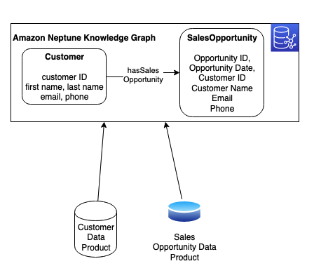
But we know more about the customer than the Customer product tells us. In the Neptune database, we maintain a knowledge graph that combines multiple products and links them through relationships. A knowledge graph allows us to combine data from different sources to gain a better understanding of a specific problem domain. In Neptune, we combine the Customer product data with an additional data product: Sales Opportunity. We ingest each product from its source into the knowledge graph and model a hasSalesOpportunity relationship between Customer and SalesOpportunity resources. The following figure shows these resources, their attributes, and their relationship.

With the AWS SDK for Pandas, we combine this data by running a query against the Neptune graph. We use a graph query language (such as SPARQL) to wrangle a representative subset of customer and sales opportunity data into a Pandas data frame (shown as Enhanced Customer View in the following figure). In the following example, we enhance customers 7 and 8 with alternate phone or email contact data from sales opportunities.

We pass that frame to Valentine and compare it to Encounter. This time, two additional encounters match a customer.

The score meets our threshold, and is high enough to share with the consumer as a possible match. To the customer browsing Customer in the mesh marketplace, we present the recommendation of Encounter, along with scoring details to support the recommendation. With this recommendation, the consumer can explore the Encounter product with greater confidence.

Conclusion

Data-driven organizations are transitioning to a data product way of thinking. Utilizing strategies like data mesh generates value on a large scale. We took this a step further by creating a blueprint to create smart recommendations by linking similar data products using graph technology and ML. In this post, we showed how an organization can augment a data catalog with additional metadata by using ML and Neptune with an automated process.

This solution solves the interoperability and linkage problem for data products. Additionally, it gives organizations real-time insights, agility, and innovation without spending time on data analysis and research. This approach creates a truly connected ecosystem with simplified access to delight your data consumers. The current solution is platform agnostic; however, in a future post we will show how to implement this using data.all (open-source software) and Amazon DataZone.

To learn more about ML in Neptune, refer to Amazon Neptune ML for machine learning on graphs. You can also explore Neptune notebooks demonstrating ML and data science for graphs. For more information about the data mesh architecture, refer to Design a data mesh architecture using AWS Lake Formation and AWS Glue. To learn more about Amazon DataZone and how you can share, search, and discover data at scale across organizational boundaries.


About the Authors


Moira Lennox
is a Senior Data Strategy Technical Specialist for AWS with 27 years’ experience helping companies innovate and modernize their data strategies to achieve new heights and allow for strategic decision-making. She has experience working in large enterprises and technology providers, in both business and technical roles across multiple industries, including health care live sciences, financial services, communications, digital entertainment, energy, and manufacturing.

Joel Farvault is Principal Specialist SA Analytics for AWS with 25 years’ experience working on enterprise architecture, data strategy, and analytics, mainly in the financial services industry. Joel has led data transformation projects on fraud analytics, claims automation, and data governance.

Mike Havey is a Solutions Architect for AWS with over 25 years of experience building enterprise applications. Mike is the author of two books and numerous articles. His Amazon author page

Accelerate HiveQL with Oozie to Spark SQL migration on Amazon EMR

Post Syndicated from Vinay Kumar Khambhampati original https://aws.amazon.com/blogs/big-data/accelerate-hiveql-with-oozie-to-spark-sql-migration-on-amazon-emr/

Many customers run big data workloads such as extract, transform, and load (ETL) on Apache Hive to create a data warehouse on Hadoop. Apache Hive has performed pretty well for a long time. But with advancements in infrastructure such as cloud computing and multicore machines with large RAM, Apache Spark started to gain visibility by performing better than Apache Hive.

Customers now want to migrate their Apache Hive workloads to Apache Spark in the cloud to get the benefits of optimized runtime, cost reduction through transient clusters, better scalability by decoupling the storage and compute, and flexibility. However, migration from Apache Hive to Apache Spark needs a lot of manual effort to write migration scripts and maintain different Spark job configurations.

In this post, we walk you through a solution that automates the migration from HiveQL to Spark SQL. The solution was used to migrate Hive with Oozie workloads to Spark SQL and run them on Amazon EMR for a large gaming client. You can also use this solution to develop new jobs with Spark SQL and process them on Amazon EMR. This post assumes that you have a basic understanding of Apache Spark, Hive, and Amazon EMR.

Solution overview

In our example, we use Apache Oozie, which schedules Apache Hive jobs as actions to collect and process data on a daily basis.

We migrate these Oozie workflows with Hive actions by extracting the HQL files, and dynamic and static parameters, and converting them to be Spark compliant. Manual conversion is both time consuming and error prone. To convert the HQL to Spark SQL, you’ll need to sort through existing HQLs, replace the parameters, and change the syntax for a bunch of files.

Instead, we can use automation to speed up the process of migration and reduce heavy lifting tasks, costs, and risks.

We split the solution into two primary components: generating Spark job metadata and running the SQL on Amazon EMR. The first component (metadata setup) consumes existing Hive job configurations and generates metadata such as number of parameters, number of actions (steps), and file formats. The second component consumes the generated metadata from the first component and prepares the run order of Spark SQL within a Spark session. With this solution, we support basic orchestration and scheduling with the help of AWS services like Amazon DynamoDB and Amazon Simple Storage Service (Amazon S3). We can validate the solution by running queries in Amazon Athena.

In the following sections, we walk through these components and how to use these automations in detail.

Generate Spark SQL metadata

Our batch job consists of Hive steps scheduled to run sequentially. For each step, we run HQL scripts that extract, transform, and aggregate input data into one final Hive table, which stores data in HDFS. We use the following Oozie workflow parser script, which takes the input of an existing Hive job and generates configurations artifacts needed for running SQL using PySpark.

Oozie workflow XML parser

We create a Python script to automatically parse the Oozie jobs, including workflow.xml, co-ordinator.xml, job properties, and HQL files. This script can handle many Hive actions in a workflow by organizing the metadata at the step level into separate folders. Each step includes the list of SQLs, SQL paths, and their static parameters, which are input for the solution in the next step.

The process consists of two steps:

  1. The Python parser script takes input of the existing Oozie Hive job and its configuration files.
  2. The script generates a metadata JSON file for each step.

The following diagram outlines these steps and shows sample output.

Prerequisites

You need the following prerequisites:

  • Python 3.8
  • Python packages:
    • sqlparse==0.4.2
    • jproperties==2.1.1
    • defusedxml== 0.7.1

Setup

Complete the following steps:

  1. Install Python 3.8.
  2. Create a virtual environment:
python3 -m venv /path/to/new/virtual/environment
  1. Activate the newly created virtual environment:
source /path/to/new/virtual/environment/bin/activate
  1. Git clone the project:
git clone https://github.com/aws-samples/oozie-job-parser-extract-hive-sql
  1. Install dependent packages:
cd oozie-job-parser-extract-hive-sql
pip install -r requirements.txt

Sample command

We can use the following sample command:

python xml_parser.py --base-folder ./sample_jobs/ --job-name sample_oozie_job_name --job-version V3 --hive-action-version 0.4 --coordinator-action-version 0.4 --workflow-version 0.4 --properties-file-name job.coordinator.properties

The output is as follows:

{'nameNode': 'hdfs://@{{/cluster/${{cluster}}/namenode}}:54310', 'jobTracker': '@{{/cluster/${{cluster}}/jobtracker}}:54311', 'queueName': 'test_queue', 'appName': 'test_app', 'oozie.use.system.libpath': 'true', 'oozie.coord.application.path': '${nameNode}/user/${user.name}/apps/${appName}', 'oozie_app_path': '${oozie.coord.application.path}', 'start': '${{startDate}}', 'end': '${{endDate}}', 'initial_instance': '${{startDate}}', 'job_name': '${appName}', 'timeOut': '-1', 'concurrency': '3', 'execOrder': 'FIFO', 'throttle': '7', 'hiveMetaThrift': '@{{/cluster/${{cluster}}/hivemetastore}}', 'hiveMySQL': '@{{/cluster/${{cluster}}/hivemysql}}', 'zkQuorum': '@{{/cluster/${{cluster}}/zookeeper}}', 'flag': '_done', 'frequency': 'hourly', 'owner': 'who', 'SLA': '2:00', 'job_type': 'coordinator', 'sys_cat_id': '6', 'active': '1', 'data_file': 'hdfs://${nameNode}/hive/warehouse/test_schema/test_dataset', 'upstreamTriggerDir': '/input_trigger/upstream1'}
('./sample_jobs/development/sample_oozie_job_name/step1/step1.json', 'w')

('./sample_jobs/development/sample_oozie_job_name/step2/step2.json', 'w')

Limitations

This method has the following limitations:

  • The Python script parses only HiveQL actions from the Oozie workflow.xml.
  • The Python script generates one file for each SQL statement and uses the sequence ID for file names. It doesn’t name the SQL based on the functionality of the SQL.

Run Spark SQL on Amazon EMR

After we create the SQL metadata files, we use another automation script to run them with Spark SQL on Amazon EMR. This automation script supports custom UDFs by adding JAR files to spark submit. This solution uses DynamoDB for logging the run details of SQLs for support and maintenance.

Architecture overview

The following diagram illustrates the solution architecture.

Prerequisites

You need the following prerequisites:

  • Version:
    • Spark 3.X
    • Python 3.8
    • Amazon EMR 6.1

Setup

Complete the following steps:

  1. Install the AWS Command Line Interface (AWS CLI) on your workspace by following the instructions in Installing or updating the latest version of the AWS CLI. To configure AWS CLI interaction with AWS, refer to Quick setup.
  2. Create two tables in DynamoDB: one to store metadata about jobs and steps, and another to log job runs.
    • Use the following AWS CLI command to create the metadata table in DynamoDB:
aws dynamodb create-table --region us-east-1 --table-name dw-etl-metadata --attribute-definitions '[ { "AttributeName": "id","AttributeType": "S" } , { "AttributeName": "step_id","AttributeType": "S" }]' --key-schema '[{"AttributeName": "id", "KeyType": "HASH"}, {"AttributeName": "step_id", "KeyType": "RANGE"}]' --billing-mode PROVISIONED --provisioned-throughput ReadCapacityUnits=5,WriteCapacityUnits=5

You can check on the DynamoDB console that the table dw-etl-metadata is successfully created.

The metadata table has the following attributes.

Attributes Type Comments
id String partition_key
step_id String sort_key
step_name String Step description
sql_base_path string Base path
sql_info list List of SQLs in ETL pipeline
. sql_path SQL file name
. sql_active_flag y/n
. sql_load_order Order of SQL
. sql_parameters Parameters in SQL and values
spark_config Map Spark configs
    • Use the following AWS CLI command to create the log table in DynamoDB:
aws dynamodb create-table --region us-east-1 --table-name dw-etl-pipelinelog --attribute-definitions '[ { "AttributeName":"job_run_id", "AttributeType": "S" } , { "AttributeName":"step_id", "AttributeType": "S" } ]' --key-schema '[{"AttributeName": "job_run_id", "KeyType": "HASH"},{"AttributeName": "step_id", "KeyType": "RANGE"}]' --billing-mode PROVISIONED --provisioned-throughput ReadCapacityUnits=5,WriteCapacityUnits=5

You can check on the DynamoDB console that the table dw-etl-pipelinelog is successfully created.

The log table has the following attributes.

Attributes Type Comments
job_run_id String partition_key
id String sort_key (UUID)
end_time String End time
error_description String Error in case of failure
expire Number Time to Live
sql_seq Number SQL sequence number
start_time String Start time
Status String Status of job
step_id String Job ID SQL belongs

The log table can grow quickly if there are too many jobs or if they are running frequently. We can archive them to Amazon S3 if they are no longer used or use the Time to Live feature of DynamoDB to clean up old records.

  1. Run the first command to set the variable in case you have an existing bucket that can be reused. If not, create a S3 bucket to store the Spark SQL code, which will be run by Amazon EMR.
export s3_bucket_name=unique-code-bucket-name # Change unique-code-bucket-name to a valid bucket name
aws s3api create-bucket --bucket $s3_bucket_name --region us-east-1
  1. Enable secure transfer on the bucket:
aws s3api put-bucket-policy --bucket $s3_bucket_name --policy '{"Version": "2012-10-17", "Statement": [{"Effect": "Deny", "Principal": {"AWS": "*"}, "Action": "s3:*", "Resource": ["arn:aws:s3:::unique-code-bucket-name", "arn:aws:s3:::unique-code-bucket-name/*"], "Condition": {"Bool": {"aws:SecureTransport": "false"} } } ] }' # Change unique-code-bucket-name to a valid bucket name

  1. Clone the project to your workspace:
git clone https://github.com/aws-samples/pyspark-sql-framework.git
  1. Create a ZIP file and upload it to the code bucket created earlier:
cd pyspark-sql-framework/code
zip code.zip -r *
aws s3 cp ./code.zip s3://$s3_bucket_name/framework/code.zip
  1. Upload the ETL driver code to the S3 bucket:
cd $OLDPWD/pyspark-sql-framework
aws s3 cp ./code/etl_driver.py s3://$s3_bucket_name/framework/

  1. Upload sample job SQLs to Amazon S3:
aws s3 cp ./sample_oozie_job_name/ s3://$s3_bucket_name/DW/sample_oozie_job_name/ --recursive

  1. Add a sample step (./sample_oozie_job_name/step1/step1.json) to DynamoDB (for more information, refer to Write data to a table using the console or AWS CLI):
{
  "name": "step1.q",
  "step_name": "step1",
  "sql_info": [
    {
      "sql_load_order": 5,
      "sql_parameters": {
        "DATE": "${coord:formatTime(coord:nominalTime(), 'yyyy-MM-dd')}",
        "HOUR": "${coord:formatTime(coord:nominalTime(), 'HH')}"
      },
      "sql_active_flag": "Y",
      "sql_path": "5.sql"
    },
    {
      "sql_load_order": 10,
      "sql_parameters": {
        "DATE": "${coord:formatTime(coord:nominalTime(), 'yyyy-MM-dd')}",
        "HOUR": "${coord:formatTime(coord:nominalTime(), 'HH')}"
      },
      "sql_active_flag": "Y",
      "sql_path": "10.sql"
    }
  ],
  "id": "emr_config",
  "step_id": "sample_oozie_job_name#step1",
  "sql_base_path": "sample_oozie_job_name/step1/",
  "spark_config": {
    "spark.sql.parser.quotedRegexColumnNames": "true"
  }
}

  1. In the Athena query editor, create the database base:
create database base;
  1. Copy the sample data files from the repo to Amazon S3:
    1. Copy us_current.csv:
aws s3 cp ./sample_data/us_current.csv s3://$s3_bucket_name/covid-19-testing-data/base/source_us_current/;

  1. Copy states_current.csv:
aws s3 cp ./sample_data/states_current.csv s3://$s3_bucket_name/covid-19-testing-data/base/source_states_current/;

  1. To create the source tables in the base database, run the DDLs present in the repo in the Athena query editor:
    1. Run the ./sample_data/ddl/states_current.q file by modifying the S3 path to the bucket you created.
    1. Run the ./sample_data/ddl/us_current.q file by modifying the S3 path to the bucket you created.

The ETL driver file implements the Spark driver logic. It can be invoked locally or on an EMR instance.

  1. Launch an EMR cluster.
    1. Make sure to select Use for Spark table metadata under AWS Glue Data Catalog settings.

  1. Add the following steps to EMR cluster.
aws emr add-steps --cluster-id <<cluster id created above>> --steps 'Type=CUSTOM_JAR,Name="boto3",ActionOnFailure=CONTINUE,Jar=command-runner.jar,Args=[bash,-c,"sudo pip3 install boto3"]'
aws emr add-steps --cluster-id <<cluster id created above>> --steps 'Name="sample_oozie_job_name",Jar="command-runner.jar",Args=[spark-submit,--py-files,s3://unique-code-bucket-name-#####/framework/code.zip,s3://unique-code-bucket-name-#####/framework/etl_driver.py,--step_id,sample_oozie_job_name#step1,--job_run_id,sample_oozie_job_name#step1#2022-01-01-12-00-01,  --code_bucket=s3://unique-code-bucket-name-#####/DW,--metadata_table=dw-etl-metadata,--log_table_name=dw-etl-pipelinelog,--sql_parameters,DATE=2022-02-02::HOUR=12::code_bucket=s3://unique-code-bucket-name-#####]' # Change unique-code-bucket-name to a valid bucket name

The following table summarizes the parameters for the spark step.

Step type Spark Application
Name Any Name
Deploy mode Client
Spark-submit options --py-files s3://unique-code-bucket-name-#####/framework/code.zip
Application location s3://unique-code-bucket-name-####/framework/etl_driver.py
Arguments --step_id sample_oozie_job_name#step1 --job_run_id sample_oozie_job_name#step1#2022-01-01-12-00-01 --code_bucket=s3://unique-code-bucket-name-#######/DW --metadata_table=dw-etl-metadata --log_table_name=dw-etl-pipelinelog --sql_parameters DATE=2022-02-02::HOUR=12::code_bucket=s3://unique-code-bucket-name-#######
Action on failure Continue

The following table summarizes the script arguments.

Script Argument Argument Description
deploy-mode Spark deploy mode. Client/Cluster.
name <jobname>#<stepname> Unique name for the Spark job. This can be used to identify the job on the Spark History UI.
py-files <s3 path for code>/code.zip S3 path for the code.
<s3 path for code>/etl_driver.py S3 path for the driver module. This is the entry point for the solution.
step_id <jobname>#<stepname> Unique name for the step. This refers to the step_id in the metadata entered in DynamoDB.
job_run_id <random UUID> Unique ID to identify the log entries in DynamoDB.
log_table_name <DynamoDB Log table name> DynamoDB table for storing the job run details.
code_bucket <s3 bucket> S3 path for the SQL files that are uploaded in the job setup.
metadata_table <DynamoDB Metadata table name> DynamoDB table for storing the job metadata.
sql_parameters DATE=2022-07-04::HOUR=00 Any additional or dynamic parameters expected by the SQL files.

Validation

After completion of EMR step you should have data on S3 bucket for the table base.states_daily. We can validate the data by querying the table base.states_daily in Athena.

Congratulations, you have converted an Oozie Hive job to Spark and run on Amazon EMR successfully.

Solution highlights

This solution has the following benefits:

  • It avoids boilerplate code for any new pipeline and offers less maintenance of code
  • Onboarding any new pipeline only needs the metadata set up—the DynamoDB entries and SQL to be placed in the S3 path
  • Any common modifications or enhancements can be done at the solution level, which will be reflected across all jobs
  • DynamoDB metadata provides insight into all active jobs and their optimized runtime parameters
  • For each run, this solution persists the SQL start time, end time, and status in a log table to identify issues and analyze runtimes
  • It supports Spark SQL and UDF functionality. Custom UDFs can be provided externally to the spark submit command

Limitations

This method has the following limitations:

  • The solution only supports SQL queries on Spark
  • Each SQL should be a Spark action like insert, create, drop, and so on

In this post, we explained the scenario of migrating an existing Oozie job. We can use the PySpark solution independently for any new development by creating DynamoDB entries and SQL files.

Clean up

Delete all the resources created as part of this solution to avoid ongoing charges for the resources:

  1. Delete the DynamoDB tables:
aws dynamodb delete-table --table-name dw-etl-metadata --region us-east-1
aws dynamodb delete-table --table-name dw-etl-pipelinelog --region us-east-1
  1. Delete the S3 bucket:
aws s3 rm s3://$s3_bucket_name --region us-east-1 --recursive
aws s3api create-bucket --bucket $s3_bucket_name --region us-east-1

  1. Stop the EMR cluster if it wasn’t a transient cluster:
aws emr terminate-clusters --cluster-ids <<cluster id created above>> 

Conclusion

In this post, we presented two automated solutions: one for parsing Oozie workflows and HiveQL files to generate metadata, and a PySpark solution for running SQLs using generated metadata. We successfully implemented these solutions to migrate a Hive workload to EMR Spark for a major gaming customer and achieved about 60% effort reduction.

For a Hive with Oozie to Spark migration, these solutions help complete the code conversion quickly so you can focus on performance benchmark and testing. Developing a new pipeline is also quick—you only need to create SQL logic, test it using Spark (shell or notebook), add metadata to DynamoDB, and test via the PySpark SQL solution. Overall, you can use the solution in this post to accelerate Hive to Spark code migration.


About the authors

Vinay Kumar Khambhampati is a Lead Consultant with the AWS ProServe Team, helping customers with cloud adoption. He is passionate about big data and data analytics.

Sandeep Singh is a Lead Consultant at AWS ProServe, focused on analytics, data lake architecture, and implementation. He helps enterprise customers migrate and modernize their data lake and data warehouse using AWS services.

Amol Guldagad is a Data Analytics Consultant based in India. He has worked with customers in different industries like banking and financial services, healthcare, power and utilities, manufacturing, and retail, helping them solve complex challenges with large-scale data platforms. At AWS ProServe, he helps customers accelerate their journey to the cloud and innovate using AWS analytics services.

How CyberSolutions built a scalable data pipeline using Amazon EMR Serverless and the AWS Data Lab

Post Syndicated from Constantin Scoarță original https://aws.amazon.com/blogs/big-data/how-cybersolutions-built-a-scalable-data-pipeline-using-amazon-emr-serverless-and-the-aws-data-lab/

This post is co-written by Constantin Scoarță and Horațiu Măiereanu from CyberSolutions Tech.

CyberSolutions is one of the leading ecommerce enablers in Germany. We design, implement, maintain, and optimize award-winning ecommerce platforms end to end. Our solutions are based on best-in-class software like SAP Hybris and Adobe Experience Manager, and complemented by unique services that help automate the pricing and sourcing processes.

We have built data pipelines to process, aggregate, and clean our data for our forecasting service. With the growing interest in our services, we wanted to scale our batch-based data pipeline to process more historical data on a daily basis and yet remain performant, cost-efficient, and predictable. To meet our requirements, we have been exploring the use of Amazon EMR Serverless as a potential solution.

To accelerate our initiative, we worked with the AWS Data Lab team. They offer joint engineering engagements between customers and AWS technical resources to create tangible deliverables that accelerate data and analytics initiatives. We chose to work through a Build Lab, which is a 2–5-day intensive build with a technical customer team.

In this post, we share how we engaged with the AWS Data Lab program to build a scalable and performant data pipeline using EMR Serverless.

Use case

Our forecasting and recommendation algorithm is fed with historical data, which needs to be curated, cleaned, and aggregated. Our solution was based on AWS Glue workflows orchestrating a set of AWS Glue jobs, which worked fine for our requirements. However, as our use case developed, it required more computations and bigger datasets, resulting into unpredictable performance and cost.

This pipeline performs daily extracts from our data warehouse and a few other systems, curates the data, and does some aggregations (such as daily average). Those will be consumed by our internal tools and generate recommendations accordingly. Prior to the engagement, the pipeline was processing 28 days’ worth of historical data in approximately 70 minutes. We wanted to extend that to 100 days and 365 days of data without having to extend the extraction window or factor in the resources configured.

Solution overview

While working with the Data Lab team, we decided to structure our efforts into two approaches. As a short-term improvement, we were looking into optimizing the existing pipeline based on AWS Glue extract, transform, and load (ETL) jobs, orchestrated via AWS Glue workflows. However, for the mid-term to long-term, we looked at EMR Serverless to run our forecasting data pipeline.

EMR Serverless is an option in Amazon EMR that makes it easy and cost-effective for data engineers and analysts to run petabyte-scale data analytics in the cloud. With EMR Serverless, we could run applications built using open-source frameworks such as Apache Spark (as in our case) without having to configure, manage, optimize, or secure clusters. The following factors influenced our decision to use EMR Serverless:

  • Our pipeline had minimal dependency on the AWS Glue context and its features, instead running native Apache Spark
  • EMR Serverless offers configurable drivers and workers
  • With EMR Serverless, we were able to take advantage of its cost tracking feature for applications
  • The need for managing our own Spark History Server was eliminated because EMR Serverless automatically creates a monitoring Spark UI for each job

Therefore, we planned the lab activities to be categorized as follows:

  • Improve the existing code to be more performant and scalable
  • Create an EMR Serverless application and adapt the pipeline
  • Run the entire pipeline with different date intervals

The following solution architecture depicts the high-level components we worked with during the Build Lab.

In the following sections, we dive into the lab implementation in more detail.

Improve the existing code

After examining our code decisions, we identified a step in our pipeline that consumed the most time and resources, and we decided to focus on improving it. Our target job for this optimization was the “Create Moving Average” job, which involves computing various aggregations such as averages, medians, and sums on a moving window. Initially, this step took around 4.7 minutes to process an interval of 28 days. However, running the job for larger datasets proved to be challenging – it didn’t scale well and even resulted in errors in some cases.

While reviewing our code, we focused on several areas, including checking data frames at certain steps to ensure that they contained content before proceeding. Initially, we used the count() API to achieve this, but we discovered that head() was a better alternative because it returns the first n rows only and is faster than count() for large input data. With this change, we were able to save around 15 seconds when processing 28 days’ worth of data. Additionally, we optimized our output writing by using coalesce() instead of repartition().

These changes managed to shave off some time, down to 4 minutes per run. However, we could achieve a better performance by using cache() on data frames before performing the aggregations, which materializes the data frame upon the following transformation. Additionally, we used unpersist() to free up executors’ memory after we were done with the mentioned aggregations. This led to a runtime of approximately 3.5 minutes for this job.

Following the successful code improvements, we managed to extend the data input to 100 days, 1 year, and 3 years. For this specific job, the coalesce() function wasn’t avoiding the shuffle operation and caused uneven data distribution per executor, so we switched back to repartition() for this job. By the end, we managed to get successful runs in 4.7, 12, and 57 minutes, using the same number of workers in AWS Glue (10 standard workers).

Adapt code to EMR Serverless

To observe if running the same job in EMR Serverless would yield better results, we configured an application that uses a comparable number of executors as in AWS Glue jobs. In the job configurations, we used 2 cores and 6 GB of memory for the driver and 20 executors with 4 cores and 16 GB of memory. However, we didn’t use additional ephemeral storage (by default, workers come with free 20 GB).

By the time we had the Build Lab, AWS Glue supported Apache Spark 3.1.1; however, we opted to use Spark 3.2.0 (Amazon EMR version 6.6.0) instead. Additionally, during the Build Lab, only x86_64 EMR Serverless applications were available, although it now also supports arm64-based architecture.

We adapted the code utilizing AWS Glue context to work with native Apache Spark. For instance, we needed to overwrite existing partitions and sync updates with the AWS Glue Data Catalog, especially when old partitions were replaced and new ones were added. We achieved this by setting spark.conf.set("spark.sql.sources.partitionOverwriteMode", "DYNAMIC") and using an MSCK REPAIR query to sync the relevant table. Similarly, we replaced the read and write operations to rely on Apache Spark APIs.

During the tests, we intentionally disabled the fine-grained auto scaling feature of EMR Serverless while running jobs, in order to observe how the code would perform with the same number of workers but different date intervals. We achieved that by setting spark.dynamicAllocation.enabled to disabled (the default is true).

For the same code, number of workers, and data inputs, we managed to get better performance results with EMR Serverless, which were 2.5, 2.9, 6, and 16 minutes for 28 days, 100 days, 1 year, and 3 years, respectively.

Run the entire pipeline with different date intervals

Because the code for our jobs was implemented in a modular fashion, we were able to quickly test all of them with EMR Serverless and then link them together to orchestrate the pipeline via Amazon Managed Workflows for Apache Airflow (Amazon MWAA).

Regarding performance, our previous pipeline using AWS Glue took around 70 minutes to run with our regular workload. However, our new pipeline, powered by Amazon MWAA-backed EMR Serverless, achieved similar results in approximately 60 minutes. Although this is a notable improvement, the most significant benefit was our ability to scale up to process larger amounts of data using the same number of workers. For instance, processing 1 year’s worth of data only took around 107 minutes to complete.

Conclusion and key takeaways

In this post, we outlined the approach taken by the CyberSolutions team in conjunction with the AWS Data Lab to create a high-performing and scalable demand forecasting pipeline. By using optimized Apache Spark jobs on customizable EMR Serverless workers, we were able to surpass the performance of our previous workflow. Specifically, the new setup resulted in 50–72% better performance for most jobs when processing 100 days of data, resulting in an overall cost savings of around 38%.

EMR Serverless applications’ features helped us have better control over cost. For example, we configured the pre-initialized capacity, which resulted in job start times of 1–4 seconds. And we set up the application behavior to start with the first submitted job and automatically stop after a configurable idle time.

As a next step, we are actively testing AWS Graviton2-based EMR applications, which come with more performance gains and lower cost.


About the Authors

 Constantin Scoarță is a Software Engineer at CyberSolutions Tech. He is mainly focused on building data cleaning and forecasting pipelines. In his spare time, he enjoys hiking, cycling, and skiing.

Horațiu Măiereanu is the Head of Python Development at CyberSolutions Tech. His team builds smart microservices for ecommerce retailers to help them improve and automate their workloads. In his free time, he likes hiking and traveling with his family and friends.

Ahmed Ewis is a Solutions Architect at the AWS Data Lab. He helps AWS customers design and build scalable data platforms using AWS database and analytics services. Outside of work, Ahmed enjoys playing with his child and cooking.

Amazon EMR on EKS widens the performance gap: Run Apache Spark workloads 5.37 times faster and at 4.3 times lower cost

Post Syndicated from Melody Yang original https://aws.amazon.com/blogs/big-data/amazon-emr-on-eks-widens-the-performance-gap-run-apache-spark-workloads-5-37-times-faster-and-at-4-3-times-lower-cost/

Amazon EMR on EKS provides a deployment option for Amazon EMR that allows organizations to run open-source big data frameworks on Amazon Elastic Kubernetes Service (Amazon EKS). With EMR on EKS, Spark applications run on the Amazon EMR runtime for Apache Spark. This performance-optimized runtime offered by Amazon EMR makes your Spark jobs run fast and cost-effectively. Also, you can run other types of business applications, such as web applications and machine learning (ML) TensorFlow workloads, on the same EKS cluster. EMR on EKS simplifies your infrastructure management, maximizes resource utilization, and reduces your cost.

We have been continually improving the Spark performance in each Amazon EMR release to further shorten job runtime and optimize users’ spending on their Amazon EMR big data workloads. As of the Amazon EMR 6.5 release in January 2022, the optimized Spark runtime was 3.5 times faster than OSS Spark v3.1.2 with up to 61% lower costs. Amazon EMR 6.10 is now 1.59 times faster than Amazon EMR 6.5, which has resulted in 5.37 times better performance than OSS Spark v3.3.1 with 76.8% cost savings.

In this post, we describe the benchmark setup and results on top of the EMR on EKS environment. We also share a Spark benchmark solution that suits all Amazon EMR deployment options, so you can replicate the process in your environment for your own performance test cases. The solution uses the TPC-DS dataset and unmodified data schema and table relationships, but derives queries from TPC-DS to support the SparkSQL test cases. It is not comparable to other published TPC-DS benchmark results.

Benchmark setup

To compare with the EMR on EKS 6.5 test result detailed in the post Amazon EMR on Amazon EKS provides up to 61% lower costs and up to 68% performance improvement for Spark workloads, this benchmark for the latest release (Amazon EMR 6.10) uses the same approach: a TPC-DS benchmark framework and the same size of TPC-DS input dataset from an Amazon Simple Storage Service (Amazon S3) location. For the source data, we chose the 3 TB scale factor, which contains 17.7 billion records, approximately 924 GB compressed data in Parquet file format. The setup instructions and technical details can be found in the aws-sample repository.

In summary, the entire performance test job includes 104 SparkSQL queries and was completed in approximately 24 minutes (1,397.55 seconds) with an estimated running cost of $5.08 USD. The input data and test result outputs were both stored on Amazon S3.

The job has been configured with the following parameters that match with the previous Amazon EMR 6.5 test:

  • EMR release – EMR 6.10.0
  • Hardware:
    • Compute – 6 X c5d.9xlarge instances, 216 vCPU, 432 GiB memory in total
    • Storage – 6 x 900 NVMe SSD build-in storage
    • Amazon EBS root volume – 6 X 20GB gp2
  • Spark configuration:
    • Driver pod – 1 instance among other 7 executors on a shared Amazon Elastic Compute Cloud (Amazon EC2) node:
      • spark.driver.cores=4
      • spark.driver.memory=5g
      • spark.kubernetes.driver.limit.cores=4.1
    • Executor pod – 47 instances distributed over 6 EC2 nodes
      • spark.executor.cores=4
      • spark.executor.memory=6g
      • spark.executor.memoryOverhead=2G
      • spark.kubernetes.executor.limit.cores=4.3
  • Metadata store – We use Spark’s in-memory data catalog to store metadata for TPC-DS databases and tables—spark.sql.catalogImplementation is set to the default value in-memory. The fact tables are partitioned by the date column, which consists of partitions ranging from 200–2,100. No statistics are pre-calculated for these tables.

Results

A single test session consists of 104 Spark SQL queries that were run sequentially. We ran each Spark runtime session (EMR runtime for Apache Spark, OSS Apache Spark) three times. The Spark benchmark job produces a CSV file to Amazon S3 that summarizes the median, minimum, and maximum runtime for each individual query.

The way we calculate the final benchmark results (geomean and the total job runtime) are based on arithmetic means. We take the mean of the median, minimum, and maximum values per query using the formula of AVERAGE(), for example AVERAGE(F2:H2). Then we take a geometric mean of the average column I by the formula GEOMEAN(I2:I105) and SUM(I2:I105) for the total runtime.

Previously, we observed that EMR on EKS 6.5 is 3.5 times faster than OSS Spark on EKS, and costs 2.6 times less. From this benchmark, we found that the gap has widened: EMR on EKS 6.10 now provides a 5.37 times performance improvement on average and up to 11.61 times improved performance for individual queries over OSS Spark 3.3.1 on Amazon EKS. From the running cost perspective, we see the significant reduction by 4.3 times.

The following graph shows the performance improvement of Amazon EMR 6.10 compared to OSS Spark 3.3.1 at the individual query level. The X-axis shows the name of each query, and the Y-axis shows the total runtime in seconds on logarithmic scale. The most significant performance gains for eight queries (q14a, q14b, q23b, q24a, q24b, q4, q67, q72) demonstrated over 10 times faster for the runtime.

Job cost estimation

The cost estimate doesn’t account for Amazon S3 storage, or PUT and GET requests. The Amazon EMR on EKS uplift calculation is based on the hourly billing information provided by AWS Cost Explorer.

  • c5d.9xlarge hourly price – $1.728
  • Number of EC2 instances – 6
  • Amazon EBS storage per GB-month – $0.10
  • Amazon EBS gp2 root volume – 20GB
  • Job run time (hour) –
    • OSS Spark 3.3.1 – 2.09
    • EMR on EKS 6.5.0 – 0.68
    • EMR on EKS 6.10.0 – 0.39
Cost component OSS Spark 3.3.1 on EKS EMR on EKS 6.5.0 EMR on EKS 6.10.0
Amazon EC2 $21.67 $7.05 $4.04
EMR on EKS $ – $1.57 $0.99
Amazon EKS $0.21 $0.07 $0.04
Amazon EBS root volume $0.03 $0.01 $0.01
Total $21.88 $8.70 $5.08

Performance enhancements

Although we improve on Amazon EMR’s performance with each release, Amazon EMR 6.10 contained many performance optimizations, making it 5.37 times faster than OSS Spark v3.3.1 and 1.59 times faster than our first release of 2022, Amazon EMR 6.5. This additional performance boost was achieved through the addition of multiple optimizations, including:

  • Enhancements to join performance, such as the following:
    • Shuffle-Hash Joins (SHJ) are more CPU and I/O efficient than Shuffle-Sort-Merge Joins (SMJ) when the costs of building and probing the hash table, including the availability of memory, are less than the cost of sorting and performing the merge join. However, SHJs have drawbacks, such as risk of out of memory errors due to its inability to spill to disk, which prevents them from being aggressively used across Spark in place of SMJs by default. We have optimized our use of SHJs so that they can be applied to more queries by default than in OSS Spark.
    • For some query shapes, we have eliminated redundant joins and enabled the use of more performant join types.
  • We have reduced the amount of data shuffled before joins and the potential for data explosions after joins by selectively pushing down aggregates through joins.
  • Bloom filters can improve performance by reducing the amount of data shuffled before the join. However, there are cases where bloom filters are not beneficial and can even regress performance. For example, the bloom filter introduces a dependency between stages that reduces query parallelism, but may end up filtering out relatively little data. Our enhancements allow bloom filters to be safely applied to more query plans than OSS Spark.
  • Aggregates with high-precision decimals are computationally intensive in OSS Spark. We optimized high-precision decimal computations to increasing their performance.

Summary

With version 6.10, Amazon EMR has further enhanced the EMR runtime for Apache Spark in comparison to our previous benchmark tests for Amazon EMR version 6.5. When running EMR workloads with the the equivalent Apache Spark version 3.3.1, we observed 1.59 times better performance with 41.6% cheaper costs than Amazon EMR 6.5.

With our TPC-DS benchmark setup, we observed a significant performance increase of 5.37 times and a cost reduction of 4.3 times using EMR on EKS compared to OSS Spark.

To learn more and get started with EMR on EKS, try out the EMR on EKS Workshop and visit the EMR on EKS Best Practices Guide page.


About the Authors

Melody YangMelody Yang is a Senior Big Data Solution Architect for Amazon EMR at AWS. She is an experienced analytics leader working with AWS customers to provide best practice guidance and technical advice in order to assist their success in data transformation. Her areas of interests are open-source frameworks and automation, data engineering and DataOps.

Ashok Chintalapati is a software development engineer for Amazon EMR at Amazon Web Services.

Connect to Amazon MSK Serverless from your on-premises network

Post Syndicated from Masudur Rahaman Sayem original https://aws.amazon.com/blogs/big-data/connect-to-amazon-msk-serverless-from-your-on-premises-network/

Amazon Managed Streaming for Apache Kafka (Amazon MSK) is a fully managed, highly available, and secure Apache Kafka service. Amazon MSK reduces the work needed to set up, scale, and manage Apache Kafka in production. With Amazon MSK, you can create a cluster in minutes and start sending data.

With Amazon MSK Serverless, you can run Apache Kafka without having to manage the underlying infrastructure. Amazon MSK will automatically provision, scale, and manage your Apache Kafka clusters, so you can focus on your applications without worrying about the operational overhead. Additionally, MSK Serverless offers fine-grained, pay-as-you-go pricing, making it a cost-effective option for organizations with unpredictable workloads.

Connecting to MSK Serverless is easy. You can set up a serverless cluster using the API or AWS Management Console in minutes. MSK Serverless provides bootstrap information as a private DNS endpoint, allowing clients to connect to the serverless Apache Kafka cluster. A common use case of using MSK Serverless is an on-premises client that needs to process real-time data streams. However, the private DNS endpoint is only accessible from virtual private clouds (VPCs) that have been configured to connect and isn’t directly resolvable from an on-premises network. This can pose a challenge for on-premises clients to discover and connect to the MSK Serverless cluster.
In this post, we guide you through a step-by-step process to connect your on-premises client to MSK Serverless, overcoming this challenge.

Solution overview

The following diagram illustrates the solution architecture.

The flow of the solution is as follows:

  1. The DNS query for your MSK endpoint is routed to a locally configured on-premises DNS server.
  2. The on-premises DNS as configured performs conditional forwarding for kafka-serverless.REPLACE-MSK-SERVERLESS-REGION.amazonaws.com to an Amazon Route 53 inbound resolver endpoint IP address.
  3. The inbound resolver endpoint performs DNS resolution by forwarding the query to the private hosted zone that was created along with the MSK Serverless cluster.
  4. The IP addresses returned by the DNS query are the private IP addresses of the interface VPC endpoint, which allow your on-premises host to establish private connectivity over AWS VPN or AWS Direct Connect.
  5. The interface endpoint is a collection of one or more elastic network interfaces with a private IP address in your account that serves as an entry point for traffic destined to a MSK Serverless service.

Note that at this time, this solution works only for MSK Serverless clusters with a single VPC.

Prerequisites

In this section, we discuss the prerequisite steps to complete in order to implement this solution.

Establish network connectivity between on premises and the AWS Cloud

To use MSK Serverless from your on-premises network, you need to establish a network connection between your on-premises environment and the VPC that you have set up for MSK Serverless. Various secure methods are available to connect your on-premises network to the AWS Cloud. Refer to Network-to-Amazon VPC connectivity options for more information.

Create a security group for allowing inbound TCP/UDP connections from your on-premises network

Create a security group with the following configurations on the same VPC that you configured for MSK Serverless:

Inbound rule:

  • Source: [On-premises CIDR range]
  • Protocol: TCP/UDP
  • Port Range: 53

Outbound rule: Leave it to default

For more information, refer to Work with security groups.

Update the MSK security group for inbound connections from your on-premises network

To ensure that your MSK Serverless cluster can be accessed from your on-premises network, you need to adjust the cluster’s security group settings to allow incoming traffic from your network on TCP port 9098. Complete the following steps:

  1. On the Amazon MSK console, choose Clusters in the navigation pane.
  2. Navigate to your serverless MSK cluster’s properties.

  1. Choose the security group associated with your MSK cluster.

Because MSK Serverless supports configuring multiple VPCs, make sure to choose the security group associated with the VPC that you configured for connecting from your on-premises network.

  1. To enable connections from your on-premises CIDR block to MSK Serverless, add an inbound rule that allows traffic on TCP port 9098 from your on-premises CIDR.

This ensures that your on-premises network can communicate with MSK Serverless on the specified port.

Configure a Route 53 inbound resolver endpoint

MSK Serverless provides a DNS endpoint that serves as the starting point for an Apache Kafka client to connect to the cluster. However, this endpoint isn’t publicly discoverable and can only be accessed from within the configured VPC. To resolve the serverless DNS endpoint outside of your VPC, you can set up a Route 53 resolver endpoint. This allows you to access the endpoint securely by creating a hybrid cloud setup over VPN or Direct Connect.

To configure the Route 53 resolver using the console, complete the following steps:

  1. On the Route 53 console, under Resolver in the navigation pane, choose Inbound endpoints.
  2. Choose Create inbound endpoint.

  1. For Endpoint name, enter the endpoint name.
  2. For VPC in the Region, choose the VPC where you configured MSK Serverless.
  3. For Security group for this endpoint, choose the security group that you created as a prerequisite for inbound TCP/UDP connections.

The security group of the inbound resolver endpoint should allow traffic from the on-premises DNS Server IP address on TCP/UDP port 53.

In the next step, you add your IP addresses, ensuring that the number of IP addresses matches the number of subnets in your MSK cluster.

  1. Choose the Availability Zones and subnets that are the same as your MSK Serverless network configuration.
  2. Select Use an IP address that is selected automatically.

  1. Choose Create inbound endpoint.

  1. Copy the inbound endpoint IP addresses.

Configure the on-premises DNS server

In this example, we use a Microsoft DNS server. To configure a conditional forwarder, complete the following steps:

  1. Open DNS Manager.
  2. Run the following command in the Run command window:
dnsmgmt.msc
  1. Choose (right-click) Conditional Forwarders under the server of your choosing, then choose New Conditional Forwarder.


In the next step, you enter kafka-serverless.REPLACE-MSK-SERVERLESS-REGION.amazonaws.com, using the IP address of Route 53 inbound resolver endpoints that you created earlier. You can find the MSK endpoint information by accessing the cluster’s client information. To learn more about getting client information, refer to Getting the bootstrap brokers for an Amazon MSK cluster.

  1. For DNS Domain, enter your endpoint name. For example, kafka-serverless.ap-southeast-2.amazonaws.com. Do not enter the entire endpoint name.
  2. Choose OK.

Test the DNS resolution

DNS (Domain Name System) uses TCP/UDP port 53. To test whether you can connect any of the Route 53 inbound endpoints, run the following command from your on-premises client:

telnet Route53-INBOUND-ENDPOINT-IP 53

For example: telnet 10.1.0.133 53

The following is a sample output:

Trying 10.1.0.133...
Connected to 10.1.0.133.
Escape character is '^]'.
Connection closed by foreign host.

Run the following command to check whether you can connect with the MSK Serverless endpoint from your on-premises client. To get the MSK Serverless endpoint information, refer to Create an MSK Serverless cluster.

dig MSK-SERVERLESS-ENDPOINT-REMOVE-PORT-NUMBER +short

For example: dig boot-abcdc9.c3.kafka-serverless.ap-southeast-2.amazonaws.com +short

The following is a sample output:

vpce-0bcb06d53aab34111-vt8yzx2b.vpce-svc-05dc791a527abcd.ap-southeast-2.vpce.amazonaws.com.
10.1.1.185
10.1.0.191

If the DNS resolution fails, check your network connectivity from on premises. For more information about troubleshooting connectivity issues, refer to How do I troubleshoot VPN tunnel connectivity to an Amazon VPC or Troubleshooting AWS Direct Connect.

After you create a serverless MSK cluster, the service automatically creates an interface VPC endpoint for the cluster. You can use the dig command as shown above to retrieve the VPC endpoint ID and its associated IP address, which confirms that you are now able to connect to the MSK Serverless cluster from your on-premises environment.

Test your Kafka client

Once you complete the configuration of the Route 53 inbound resolver endpoint and on-premises DNS server, you can test your Kafka client from an on-premises network. For instructions, refer to Create a client machine. This documentation guides you through the necessary steps to set up your client machine and verify that it can successfully connect to your MSK cluster from your on-premises network.

Conclusion

MSK Serverless makes it easy for you to manage your data. You don’t have to worry about setting up and running your own Kafka cluster, which saves time and effort. In this post, we explored the option of on-premises connectivity with MSK Serverless and how it can greatly benefit organizations. By establishing this connection, you can gain access to a wide range of real-time analytics use case possibilities and unlock the full potential of your data.

We encourage you to try on-premises connectivity with MSK serverless.


About the Authors

Masudur Rahaman Sayem is a Streaming Data Architect at AWS. He works with AWS customers globally to design and build data streaming architectures to solve real-world business problems. He specializes in optimizing solutions that use streaming data services and NoSQL. Sayem is very passionate about distributed computing.

Akeef Khan is a Solutions Architect at Amazon Web Services. He helps SMB Greenfield customers adopt the cloud. Whilst being a generalist SA, Akeef is passionate about networking.

How Morningstar used tag-based access controls in AWS Lake Formation to manage permissions for an Amazon Redshift data warehouse

Post Syndicated from Don Drake original https://aws.amazon.com/blogs/big-data/how-morningstar-used-tag-based-access-controls-in-aws-lake-formation-to-manage-permissions-for-an-amazon-redshift-data-warehouse/

This post was co-written by Ashish Prabhu, Stephen Johnston, and Colin Ingarfield at Morningstar and Don Drake, at AWS.

With “Empowering Investor Success” as the core motto, Morningstar aims at providing our investors and advisors with the tools and information they need to make informed investment decisions.

In this post, Morningstar’s Data Lake Team Leads discuss how they utilized tag-based access control in their data lake with AWS Lake Formation and enabled similar controls in Amazon Redshift.

The business challenge

At Morningstar, we built a data lake solution that allows our consumers to easily ingest data, make it accessible via the AWS Glue Data Catalog, and grant access to consumers to query the data via Amazon Athena. In this solution, we were required to ensure that the consumers could only query the data to which they had explicit access. To enforce our access permissions, we chose Lake Formation tag-based access control (TBAC). TBAC helps us categorize the data into a simple, broad level or a complex, more granular level using tags and then grant consumers access to those tags based on what group of data they need. Tag-based entitlements allow us to have a flexible and manageable entitlements system that solves our complex entitlements scenarios.

However, our consumers pushed us for better query performance and enhanced analytical capabilities. We realized we needed a data warehouse to cater to all of these consumer requirements, so we evaluated Amazon Redshift. Amazon Redshift provides us with features that we could use to work with our consumers and enable their analytical requirements:

  • Better performance for consumers’ analytical requirements
  • Ability to tune query performance with user-specified sort keys and distribution keys
  • Ability to have different representations of the same data via views and materialized views
  • Consistent query performance regardless of concurrency

Many new Amazon Redshift features helped solve and scale our analytical query requirements, specifically Amazon Redshift Serverless and Amazon Redshift data sharing.

Because our Lake Formation-enforced data lake is a central data repository for all our data, it makes sense for us to flow the data permissions from the data lake into Amazon Redshift. We utilize AWS Identity and Access Management (IAM) authentication and want to centralize the governance of permissions based on IAM roles and groups. For each AWS Glue database and table, we have a corresponding Amazon Redshift schema and table. Our goal was to ensure customers who have access to AWS Glue tables via Lake Formation also have access to the corresponding tables in Amazon Redshift.

However, we faced a problem with user-based entitlements as we moved to Amazon Redshift.

The entitlements problem

Even though we added Amazon Redshift as part of our overall solution, the entitlement requirements and challenges that came with it remained the same for our users consuming via Lake Formation. At the same time, we had to find a way to implement entitlements in our Amazon Redshift data warehouse with the same set of tags that we had already defined in Lake Formation. Amazon Redshift supports resource-based entitlements but doesn’t support tag-based entitlements. The challenge we had to overcome was how to map our existing tag-based entitlements in Lake Formation to the resource-based entitlements in Amazon Redshift.

The data in the AWS Glue Data Catalog needed to be also loaded in the Amazon Redshift data warehouse native tables. This was necessary so that the users get a familiar list of schema and tables that they are accustomed to seeing in the Data Catalog when accessing via Athena. This way, our existing data lake consumers could easily transition to Amazon Redshift.

The following diagram illustrates the structure of the AWS Glue Data Catalog mapped 1:1 with the structure of our Amazon Redshift data warehouse.

Shows mapping of Glue databases and tables to Redshift schemas and tables.

We wanted to utilize the ontology of tags in Lake Formation to also be used on the datasets in Amazon Redshift so that consumers could be granted access to the same datasets in both places. This enabled us to have a single entitlement policy source API that would grant appropriate access to both our Amazon Redshift tables as well as the corresponding Lake Formation tables based on the Lake Formation tag-based policies.

Entitlement Policy Source is used by Lake Formation and Redshift

To solve this problem, we needed to build our own solution to convert the tag-based policies in Lake Formation into grants and revokes in the resource-based entitlements in Amazon Redshift.

Solution overview

To solve this mismatch, we wanted to synchronize our Lake Formation tag ontology and classifications to the Amazon Redshift permission model. To do this, we map Lake Formation tags and grants to Amazon Redshift grants with the following steps:

  1. Map all the resources (databases, schemas, tables, and more) in Lake Formation that are tagged to their equivalent Amazon Redshift tables.
  2. Translate each policy in Lake Formation on a tag expression to a set of Amazon Redshift table grants and revokes.

The net result is that when there is a tag or policy change in Lake Formation, a corresponding set of grants or revokes are made to the equivalent Amazon Redshift tables to keep our entitlements in sync.

Map all tagged resources in Lake Formation to Amazon Redshift equivalents

The tag-based access control of Lake Formation allowed us to apply multiple tags on a single resource (database and table) in the AWS Glue Data Catalog. If visualized in a mapping form, the resource tagging can be displayed as how multiple tags on a single table would be flattened into individual entitlements on Amazon Redshift tables.

Mapping of tags in Lake Formation to Redshift tables

Translate tags to Amazon Redshift grants and revokes

To enable the migration of the tag-based policy enforced in Lake Formation, the permissions can be converted into simple grants and revokes that can be done on a per-group level.

There are two fundamental parts to a tag policy: the principal_id and the tag expression (for example, “Acess Level” = “Public”). Assuming that we have an Amazon Redshift database group for each principal_id, then the resources that represent the tag expression can be permissioned accordingly. We plan on migrating from database groups to database roles in a future implementation.

mapping of tags to Redshift user group

The solution implementation

The implementation of this solution led us to develop two components:

  • The mapper service
  • The Amazon Redshift data configuration

The mapper service can be thought of as a translation service. As the name suggests, it has the core business logic to map the tag and policy information into resource-based grants and revokes in Amazon Redshift. It needs to mimic the behavior of Lake Formation when handling the tag policy translation.

To do this translation, the mapper needs to understand and store the metadata at two levels:

  • Understanding what resource in Amazon Redshift is to be tagged with what value
  • Tracking the grants and revokes already performed so they can be updated with changes in the policy

To do this, we created a config schema in our Amazon Redshift cluster, which currently stores all the configurations.

As part of our implementation, we store the mapped (translated) information in Amazon Redshift. This allows us to incrementally update table grants as Lake Formation tags or policies changed. The following diagram illustrates this schema.

schema of configuration stored in Redshift

Business impact and value

The solution we put together has created key business impacts and values out of the current implementation and allows us greater flexibility in the future.

It allows us to get the data to our users faster with the tag policies applied in Lake Formation and translated directly to permissions in Amazon Redshift with immediate effect. It also allows us to have consistency in permissions applied in both Lake Formation and Amazon Redshift, based on the effective permissions derived from tag policies. And all this happens via a single source that grants and revokes permissions across the board, instead of managing them separately.

If we translate this into the business impact and business value that we generate, the solution improves the time to market of our data, but at the same time provides consistent entitlements across the business-driven categories that we define as tags.

The solution also opens up solutions to add more impact as our product scales both horizontally and vertically. There are potential solutions we could implement in terms of automation, users self-servicing their permissions, auditing, dashboards, and more. As our business scales, we expect to take advantage of these capabilities.

Conclusion

In this post, we shared how Morningstar utilized tag-based access control in our data lake with Lake Formation and enabled similar controls in Amazon Redshift. We developed two components that handle mapping of the tag-based access controls to Amazon Redshift permissions. This solution has improved the time to market for our data and provides consistent entitlements across different business-driven categories.

If you have any questions or comments, please leave them in the comments section.


About the Authors

Ashish Prabhu is a Senior Manager of Software Engineering in Morningstar, Inc. He focuses on the solutioning and delivering the different aspects of Data Lake and Data Warehouse for Morningstar’s Enterprise Data and Platform Team. In his spare time he enjoys playing basketball, painting and spending time with his family.

Stephen Johnston is a Distinguished Software Architect at Morningstar, Inc. His focus is on data lake and data warehousing technologies for Morningstar’s Enterprise Data Platform team.

Colin Ingarfield is a Lead Software Engineer at Morningstar, Inc. Based in Austin, Colin focuses on access control and data entitlements on Morningstar’s growing Data Lake platform.

Don Drake is a Senior Analytics Specialist Solutions Architect at AWS. Based in Chicago, Don helps Financial Services customers migrate workloads to AWS.

Patterns for updating Amazon OpenSearch Service index settings and mappings

Post Syndicated from Mikhail Vaynshteyn original https://aws.amazon.com/blogs/big-data/patterns-for-updating-amazon-opensearch-service-index-settings-and-mappings/

Amazon OpenSearch Service is used for a broad set of use cases like real-time application monitoring, log analytics, and website search at scale. As your domain ages and you add additional consumers, you need to reevaluate and change the domain’s configuration to handle additional storage and compute needs. You want to minimize downtime and performance impact as you make these changes.

Customers have been seeking guidance on best practices and patterns for changing index settings without an index maintenance window or affecting overall performance of the OpenSearch Service domain. This is part one of a two-part series, in which we show how to make settings changes to OpenSearch Service indexes with little to no downtime while supporting active producers and consumers of the data.

Indexes in OpenSearch Service

In OpenSearch Service, data must be indexed before it can be queried. Indexing is the method by which search engines organize data for fast retrieval. The resulting structure is called, fittingly, an index. All operations performed on an index are done via index APIs. Also, each index contains index mappings, which define field names and data types in the index. Data producers can add new fields with data types to an index. Index mappings can’t change throughout the index lifecycle.

OpenSearch Service indexes have two types of settings that periodically need adjustments as the profile of your workload changes:

  • Dynamic – Settings that can be changed on the index at any time
  • Static – Settings that can only be defined at the index creation time and can’t be changed throughout the index lifecycle

Dynamic index settings can be changed at any time using the update settings API. While the OpenSearch Service domain is performing instructed operations on dynamic index settings, the index doesn’t require a downtime. Changes to most dynamic index settings won’t trigger background tasks that affect the overall utilization of domain resources; however, some settings such as increasing the number of replicas via index.number_of_replicas or index.auto_expand_replicas, and depending on the domain’s configuration, can cause a temporary increase in resource utilization while the domain adds replicas. We recommend maintaining at least one replica for redundancy reasons, and multiple replicas for high query throughput use cases.

Static index settings such as mapping and shard count are defined at index creation time and can’t be changed throughout the index lifecycle. In this post, we focus on patterns and best practices for working with static index settings, such as changing shard count and patterns for updating index mappings.

All operations and procedures that we cover in this post are issued directly to the OpenSearch REST API or via the Dev Tools in OpenSearch Dashboards.

As with any use case, there is a spectrum of solutions and constraints to be considered. We start with a few simple foundational patterns and build on them, accounting for use cases with more operational constraints and working with large datasets.

Solution overview

OpenSearch Service has a default sharding strategy of 5:1, where each index is divided into five primary shards. Within each index, each primary shard also has its own replica. OpenSearch Service automatically assigns primary shards and replica shards to separate data nodes.

It’s not possible to increase the primary shard number of an existing index, meaning an index must be recreated if you want to increase the primary shard count.

The _reindex operation is ideal for creating destination indexes with updated shards and mapping settings. The _reindex operation is resource intensive. We recommend disabling replicas in your destination index by setting number_of_replicas to 0 and re-enable replicas when the reindex process is complete. If you have your data in a second, durable store, the simplest thing to do is pause updates and reindex from the source. But that’s not always possible. In this post, we share several patterns that enable you to update even static index settings like shard count.

One the major advantages of using the _reindex operation is that it doesn’t require placing the source index in a read-only mode (data producers may continue to write the data while reindexing is in progress). Also, the _reindex operation enables reprocessing, transformation, and reindexing a subset of documents and even selectively combining documents from multiple indexes. With the _reindex operation, you can copy all or a subset of documents that you select through a query to another index. In its most basic form, the _reindex operation requires you to specify a source and a destination index and configuration parameters.

The following are the some of the use cases supported by the reindex API:

  • Reindexing all documents
  • Reindexing from a remote cluster when transferring data between clusters
  • Reindexing a subset of documents that match a search query
  • Combining one or more indexes
  • Transforming documents during reindexing

To increase the shard count, you create a new index, set number_of_shards to your desired primary shard count, set number_of_replicas to 0, update the new index mapping based on your requirement, and run the reindex API operation. After the _reindex operation is complete, we recommend updating number_of_replicas in the destination index settings to achieve your desired level of replica shards.

In the following sections, we provide a walkthrough of the reindex API operation. Note that the patterns and procedures presented in this post have been validated on Amazon OpenSearch Service version 1.3.

Prerequisites

The source of the documents must be stored in the index (the “_source” setting at the index mappings level must be set to “enabled”:true, which is the default). The _reindex operation can’t be used without source documents.

Create the destination index with your desired mapping (field or data type). For demonstration purposes, our source index has a field ratings defined as long, and we want the same field to use the float data type in the destination index:

GET /source_index_name/mappings
{  
  "source_index_name": {
    "mappings" : {
      "properties" : {
        "ratings " : {
          "type" : "long"
        },
…
      }
    }
  }
}

PUT /destination_index_name
{
  "settings": {
    "index": {
      "number_of_shards": <DESIRED_NUMBER_OF_PRIMARY_SHARDS>,
      "number_of_replicas": 0
    }
  },
  "mappings": {
    "properties" : {
      "ratings" : {
          "type" : "float"
        },
…
    }
  }
}

Ensure that you have sufficient disk space on each hot tier data node to house the new index primary shards and, depending on your configuration, replica shards. If disk space is insufficient, perform an update operation on the OpenSearch Service domain to add the required storage capacity. Depending on storage requirements, you may need to migrate the OpenSearch Service domain to a different instance type, because nodes have constraints on the EBS volume size that can be mounted to each instance type. Issue the following operation to validate available disk space:

GET _cat/allocation?v

The following screenshot shows the output.

Check the disk.avail metric for hot storage tier nodes to validate your available disk space.

Use the reindex API operation

The _reindex operation snapshots the index at the beginning of its run and performs processing on a snapshot to minimize impact on the source index. The source index can still be used for querying and processing the data. Although the _reindex operation can run both synchronously and asynchronously, we recommend using an asynchronous run. You can monitor the progress of the _reindex operation, cancel its run, or throttle its run using the _task, _cancel, and _rethrottle operations, respectively.

Because the _reindex operation doesn’t require the source index placed in a read-only mode, query and index update operations are free to continue.

Use the reindex API with the following command:

POST _reindex?wait_for_completion=false
{
  "source": {
	"index": "source_index_name"
  },
  "dest": {
	"index": "destination_index_name",
	"op_type" : "index"
  }
}

The source indexes as part of the _reindex API operation can be supplemented with a query for reindexing a subset of documents and storing them in the destination index. Progress of the re-indexing operation can be monitored via tasks API operation:

GET _tasks

Note that the _reindex operation can be throttled via a _rethrottle API or settings passed as a parameter. You can cancel the task with the _cancel operation:

POST _tasks/TASK_ID/_cancel

The following screenshot shows the output of the _reindex operation for reindexing from source_index_name to destination_index_name.

When the operation is complete, both consumers and producers of the source indexes or aliases need to re-point to the destination index and the same _reindex operation needs to run again to catch up on any create, update, or delete operations performed on the source indexes while the initial _reindex operation was running. This step is required because the _reindex operation is running on a snapshot of the index. At this time, the _reindex operation needs to run with “op_type”:”create” to realign missing and out-of-version documents. See the following API command:

POST _reindex?wait_for_completion=false
{
"conflicts":"proceed",
  "source": {
	"index": "source_index_name"
  },
  "dest": {
	"index": "destination_index_name",
	"op_type" : "create"
  }
}

After the operation is complete and data integrity in the destination index is confirmed, you can delete the source index to reclaim disk space.

Increase index shard count using the split index API

The split index API and shrink index API cover a large array of use cases and present with low resource utilization in the domain. However, these APIs require closing the index for write operations and don’t address use cases that require changes to the mapping settings.

In OpenSearch Service, the number_of_shards index setting is immutable and defined at the time when the index is created. However, although this setting is immutable, there are several patterns to increase or decrease index shard count without needing to explicitly reindex the data. You can alternatively use the split index API to increase index shard count in the environments that can suspend write operations. The split index API provides a simplified way of creating a new index with a different shard setting and without reindexing your data. The split index API operation creates a new index based off of a read-only index with a desired number of primary shards.

In OpenSearch Service, an index alias is a virtual index name that can point to one or more indexes. Referencing to indexes using aliases in your applications allows you to avoid index name changes. Index aliases are used to point consumers and producers to a new index after the split index API operation is complete.

Although the majority of use cases focus on increasing a number of shards on an existing index due to data growth, there are also instances where you need to reduce the number of shards on an existing index. Such cases occasionally happen when an actual index size is less than what was anticipated when the index was created, and you want to align with a shard strategy for operational best practices for OpenSearch Service. In cases where you need to reduce a number of shards on an index, you can use the shrink index API to achieve this task.

Conclusion

In this post, we reviewed best practices when reindexing data for making changes in OpenSearch Service static index settings and mappings that require little or no index downtime. We also covered use of the split index and shrink index APIs for changing the primary index shard count for use cases where the index can be placed in a read-only state.

In our next post, we’ll explore patterns for remote indexing to alleviate load and resource utilization on the source OpenSearch Service domain.


About the Authors

Mikhail Vaynshteyn is a Solutions Architect with Amazon Web Services. Mikhail works with healthcare and life sciences customers to build solutions that help improve patients’ outcomes. Mikhail specializes in data analytics services.

Sukhomoy Basak is a Solutions Architect at Amazon Web Services, with a passion for data and analytics solutions. Sukhomoy works with enterprise customers to help them architect, build, and scale applications to achieve their business outcomes.

Generic orchestration framework for data warehousing workloads using Amazon Redshift RSQL

Post Syndicated from Akhil B original https://aws.amazon.com/blogs/big-data/generic-orchestration-framework-for-data-warehousing-workloads-using-amazon-redshift-rsql/

Tens of thousands of customers run business-critical workloads on Amazon Redshift, AWS’s fast, petabyte-scale cloud data warehouse delivering the best price-performance. With Amazon Redshift, you can query data across your data warehouse, operational data stores, and data lake using standard SQL. You can also integrate AWS services like Amazon EMR, Amazon Athena, Amazon SageMaker, AWS Glue, AWS Lake Formation, and Amazon Kinesis to take advantage of all of the analytic capabilities in the AWS Cloud.

Amazon Redshift RSQL is a native command-line client for interacting with Amazon Redshift clusters and databases. You can connect to an Amazon Redshift cluster, describe database objects, query data, and view query results in various output formats. You can use Amazon Redshift RSQL to replace existing extract, transform, load (ETL) and automation scripts, such as Teradata BTEQ scripts. You can wrap Amazon Redshift RSQL statements within a shell script to replicate existing functionality in the on-premise systems. Amazon Redshift RSQL is available for Linux, Windows, and macOS operating systems.

This post explains how you can create a generic configuration-driven orchestration framework using AWS Step Functions, Amazon Elastic Compute Cloud (Amazon EC2), AWS Lambda, Amazon DynamoDB, and AWS Systems Manager to orchestrate RSQL-based ETL workloads. If you’re migrating from legacy data warehouse workloads to Amazon Redshift, you can use this methodology to orchestrate your data warehousing workloads.

Solution overview

Customers migrating from legacy data warehouses to Amazon Redshift may have a significant investment in proprietary scripts like Basic Teradata Query (BTEQ) scripting for database automation, ETL, or other tasks. You can now use the AWS Schema Conversion Tool (AWS SCT) to automatically convert proprietary scripts like BTEQ scripts to Amazon Redshift RSQL scripts. The converted scripts run on Amazon Redshift with little to no changes. To learn about new options for database scripting, refer to Accelerate your data warehouse migration to Amazon Redshift – Part 4.

During such migrations, you may also want to modernize your current on-premises, third-party orchestration tools with a cloud-native framework to replicate and enhance your current orchestration capability. Orchestrating data warehouse workloads includes scheduling the jobs, checking if the pre-conditions have been met, running the business logic embedded within RSQL, monitoring the status of the jobs, and alerting if there are any failures.

This solution allows on-premises customers to migrate to a cloud-native orchestration framework that uses AWS serverless services such as Step Functions, Lambda, DynamoDB, and Systems Manager to run the Amazon Redshift RSQL jobs deployed on a persistent EC2 instance. You can also deploy the solution for greenfield implementations. In addition to meeting functional requirements, this solution also provides full auditing, logging, and monitoring of all ETL and ELT processes that are run.

To ensure high availability and resilience, you can use multiple EC2 instances that are a part of an auto scaling group along with Amazon Elastic File System (Amazon EFS) to deploy and run the RSQL jobs. When using auto scaling groups, you can install RSQL onto the EC2 instance as a part of the bootstrap script. You can also deploy the Amazon Redshift RSQL scripts onto the EC2 instance using AWS CodePipeline and AWS CodeDeploy. For more details, refer to Auto Scaling groups, the Amazon EFT User Guide, and Integrating CodeDeploy with Amazon EC2 Auto Scaling.

The following diagram illustrates the architecture of the orchestration framework.

Architecture Diagram

The key components of the framework are as follows:

  1. Amazon EventBridge is used as the ETL workflow scheduler, and it triggers a Lambda function at a preset schedule.
  2. The function queries a DynamoDB table for the configuration associated to the RSQL job and queries the status of the job, run mode, and restart information for that job.
  3. After receiving the configuration, the function triggers a Step Functions state machine by passing the configuration details.
  4. Step Functions starts running different stages (like configuration iteration, run type check, and more) of the workflow.
  5. Step Functions uses the Systems Manager SendCommand API to trigger the RSQL job and goes into a paused state with TaskToken. The RSQL scripts are persisted on an EC2 instance and are wrapped in a shell script. Systems Manager runs an AWS-RunShellScript SSM document to run the RSQL job on the EC2 instance.
  6. The RSQL job performs ETL and ELT operations on the Amazon Redshift cluster. When it’s complete, it returns a success/failure code and status message back to the calling shell script.
  7. The shell script calls a custom Python module with the success/failure code, status message, and the callwait TaskToken that was received from Step Functions. The Python module logs the RSQL job status in the job audit DynamoDB audit table, and exports logs to the Amazon CloudWatch log group.
  8. The Python module then performs a SendTaskSuccess or SendTaskFailure API call based on the RSQL job run status. Based on the status of the RSQL job, Step Functions either resumes the flow or stops with failure.
  9. Step Functions logs the workflow status (success or failure) in the DynamoDB workflow audit table.

Prerequisites

You should have the following prerequisites:

Deploy AWS CDK stacks

Complete the following steps to deploy your resources using the AWS CDK:

  1. Clone the GitHub repo:
    git clone https://github.com/aws-samples/amazon-redshift-rsql-orchestration-framework.git

  2. Update the following the environment parameters in cdk.json (this file can be found in the infra directory):
    1. ec2_instance_id – The EC2 instance ID on which RSQL jobs are deployed
    2. redshift_secret_id – The name of the Secrets Manager key that stores the Amazon Redshift database credentials
    3. rsql_script_path – The absolute directory path in the EC2 instance where the RSQL jobs are stored
    4. rsql_log_path – The absolute directory path in the EC2 instance used for storing the RSQL job logs
    5. rsql_script_wrapper – The absolute directory path of the RSQL wrapper script (rsql_trigger.sh) on the EC2 instance.

    The following is a sample cdk.json file after being populated with the parameters

        "environment": {
          "ec2_instance_id" : "i-xxxx",
          "redshift_secret_id" : "blog-secret",
          "rsql_script_path" : "/home/ec2-user/blog_test/rsql_scripts/",
          "rsql_log_path" : "/home/ec2-user/blog_test/logs/",
          "rsql_script_wrapper" : "/home/ec2-user/blog_test/instance_code/rsql_trigger.sh"
        }
    

  3. Deploy the AWS CDK stack with the following code:
    cd amazon-redshift-rsql-orchestration-framework/lambdas/lambda-layer/
    sh zip_lambda_layer.sh
    cd ../../infra/
    python3 -m venv ./venv
    source .venv/bin/activate
    pip install -r requirements.txt
    cdk bootstrap <AWS Account ID>/<AWS Region>
    cdk deploy --all

Let’s look at the resources the AWS CDK stack deploys in more detail.

CloudWatch log group

A CloudWatch log group (/ops/rsql-logs/) is created, which is used to store, monitor, and access log files from EC2 instances and other sources.

The log group is used to store the RSQL job run logs. For each RSQL script, all the stdout and stderr logs are stored as a log stream within this log group.

DynamoDB configuration table

The DynamoDB configuration table (rsql-blog-rsql-config-table) is the basic building block of this solution. All the RSQL jobs, restart information and run mode (sequential or parallel), and sequence in which the jobs are to be run are stored in this configuration table.

The table has the following structure:

  • workflow_id – The identifier for the RSQL-based ETL workflow.
  • workflow_description – The description for the RSQL-based ETL workflow.
  • workflow_stages – The sequence of stages within a workflow.
  • execution_type – The type of run for RSQL jobs (sequential or parallel).
  • stage_description – The description for the stage.
  • scripts – The list of RSQL scripts to be run. The RSQL scripts must be placed in the location defined in a later step.

The following is an example of an entry in the configuration table. You can see the workflow_id is blog_test_workflow and the description is Test Workflow for Blog.

It has three stages that are triggered in the following order: Schema & Table Creation Stage, Data Insertion Stage 1, and Data Insertion Stage 2. The stage Schema & Table Creation Stage has two RSQL jobs running sequentially, and Data Insertion Stage 1 and Data Insertion Stage 2 each have two jobs running in parallel.

{
	"workflow_id": "blog_test_workflow",
	"workflow_description": "Test Workflow for Blog",
	"workflow_stages": [{
			"execution_flag": "y",
			"execution_type": "sequential",
			"scripts": [
				"rsql_blog_script_1.sh",
				"rsql_blog_script_2.sh"
			],
			"stage_description": "Schema & Table Creation Stage"
		},
		{
			"execution_flag": "y",
			"execution_type": "parallel",
			"scripts": [
				"rsql_blog_script_3.sh",
				"rsql_blog_script_4.sh"
			],
			"stage_description": "Data Insertion Stage 1"
		},
		{
			"execution_flag": "y",
			"execution_type": "parallel",
			"scripts": [
				"rsql_blog_script_5.sh",
				"rsql_blog_script_6.sh"
			],
			"stage_description": "Data Insertion Stage 2"
		}
	]
}

DynamoDB audit tables

The audit tables store the run details for each RSQL job within the ETL workflow with a unique identifier for monitoring and reporting purposes. The reason why there are two audit tables is because one table stores the audit information at a RSQL job level and the other stores it at a workflow level.

The job audit table (rsql-blog-rsql-job-audit-table) has the following structure:

  • job_name – The name of the RSQL script
  • workflow_execution_id – The run ID for the workflow
  • execution_start_ts – The start timestamp for the RSQL job
  • execution_end_ts – The end timestamp for the RSQL job
  • execution_status – The run status of the RSQL job (Running, Completed, Failed)
  • instance_id – The EC2 instance ID on which the RSQL job is run
  • ssm_command_id – The Systems Manager command ID used to trigger the RSQL job
  • workflow_id – The workflow_id under which the RSQL job is run

The workflow audit table (rsql-blog-rsql-workflow-audit-table) has the following structure:

  • workflow_execution_id – The run ID for the workflow
  • workflow_id – The identifier for a particular workflow
  • execution_start_ts – The start timestamp for the workflow
  • execution_status – The run status of the workflow or state machine (Running, Completed, Failed)
  • rsql_jobs – The list of RSQL scripts that are a part of the workflow
  • execution_end_ts – The end timestamp for the workflow

Lambda functions

The AWS CDK creates the Lambda functions that retrieve the config data from the DynamoDB config table, update the audit details in DynamoDB, trigger the RSQL scripts on the EC2 instance, and iterate through each stage. The following is a list of the functions:

  • rsql-blog-master-iterator-lambda
  • rsql-blog-parallel-load-check-lambda
  • rsql-blog-sequential-iterator-lambda
  • rsql-blog-rsql-invoke-lambda
  • rsql-blog-update-audit-ddb-lambda

Step Functions state machines

This solution implements a Step Functions callback task integration pattern that enables Step Functions workflows to send a token to an external system via multiple AWS services.

The AWS CDK deploys the following state machines:

  • RSQLParallelStateMachine – The parallel state machine is triggered if the execution_type for a stage in the configuration table is set to parallel. The Lambda function with a callback token is triggered in parallel for each of the RSQL scripts using a Map state.
  • RSQLSequentialStateMachine – The sequential state machine is triggered if the execution_type for a stage in the configuration table is set to sequential. This state machine uses a iterator design pattern to run each RSQL job within the stage as per the sequence mentioned in the configuration.
  • RSQLMasterStatemachine – The primary state machine iterates through each stage and triggers different state machines based on the run mode (sequential or parallel) using a Choice state.

Move the RSQL script and instance code

Copy the instance_code and rsql_scripts directories (present in the GitHub repo) to the EC2 instance. Make sure the framework directory within instance_code is copied as well.

The following screenshots show that the instance_code and rsql_scripts directories are copied to the same parent folder on the EC2 instance.

Instance Code Scripts Image
Instance Code EC2 Copy Image
RSQL Script Image
RSQL Script EC2 Copy Image

RSQL script run workflow

To further illustrate the mechanism to run the RSQL scripts, see the following diagram.

RSQL Script Workflow Diagram

The Lambda function, which gets the configuration details from the configuration DynamoDB table, triggers the Step Functions workflow, which performs the following steps:

  1. A Lambda function defined as a workflow step receives the Step Functions TaskToken and configuration details.
  2. The TaskToken and configuration details are passed onto the EC2 instance using the Systems Manger SendCommand API call. After the Lambda function is run, the workflow branch goes into paused state and waits for a callback token.
  3. The RSQL scripts are run on the EC2 instance, which perform ETL and ELT on Amazon Redshift. After the scripts are run, the RSQL script passes the completion status and TaskToken to a Python script. This Python script is embedded within the RSQL script.
  4. The Python script updates the RSQL job status (success/failure) in the job audit DynamoDB table. It also exports the RSQL job logs to the CloudWatch log group.
  5. The Python script passes the RSQL job status (success/failure) and the status message back to the Step Functions workflow along with TaskToken using the SendTaskSuccess or SendTaskFailure API call.
  6. Depending on the job status received, Step Functions either resumes the workflow or stops the workflow.

If EC2 auto scaling groups are used, then you can use the Systems Manager SendCommand to ensure resilience and high availability by specifying one or more EC2 instances (that are a part of the auto scaling group). For more information, refer to Run commands at scale.

When multiple EC2 instances are used, set the max-concurrency parameter of the RunCommand API call to 1, which makes sure that the RSQL job is triggered on only one EC2 instance. For further details, refer to Using concurrency controls.

Run the orchestration framework

To run the orchestration framework, complete the following steps:

  1. On the DynamoDB console, navigate to the configuration table and insert the configuration details provided earlier. For instructions on how to insert the example JSON configuration details, refer to Write data to a table using the console or AWS CLI.DynamoDB Config Insertion
  2. On the Lambda console, open the rsql-blog-rsql-workflow-trigger-lambda function and choose Test.Workflow Trigger Lambda Function
  3. Add the test event similar to the following code and choose Test:
    {
    	"workflow_id": "blog_test_workflow",
    	"workflow_execution_id": "demo_test_26"
    }

    Workflow Trigger Lambda function Payload

  4. On the Step Functions console, navigate to the rsql-master-state-machine function to open the details page.RSQL Master Step Function
  5. Choose Edit, then choose Workflow Studio New. The following screenshot shows the primary state machine.RSQL Master Step Function Flow
  6. Choose Cancel to leave Workflow Studio, then choose Cancel again to leave edit mode. You’re directed back to the details page.
    RSQL Master Step Function Details
  7. On the Executions tab, choose the latest run.
    RSQL Master Step Function Execution
  8. From the Graph view, you can check the status of each state by choosing it. Every state that uses an external resource has a link to it on the Details tab.RSQL Master Step Function Execution Graph
  9. The orchestration framework runs the ETL load, which consists of the following sample RSQL scripts:
    • rsql_blog_script_1.sh – This script creates a schema rsql_blog within the database
    • rsql_blog_script_2.sh – This script creates a table blog_table within the schema created in the earlier script
    • rsql_blog_script_3.sh – Inserts one row into the table created in the previous script
    • rsql_blog_script_4.sh – Inserts one row into the table created in the previous script
    • rsql_blog_script_5.sh – Inserts one row into the table created in the previous script
    • rsql_blog_script_6.sh – Inserts one row into the table created in the previous script

You need to replace these RSQL scripts with the RSQL scripts developed for your workloads by inserting the relevant configuration details into the configuration DynamoDB table (rsql-blog-rsql-config-table).

Validation

After you run the framework, you’ll find a schema (called rsql_blog) with one table (called blog_table) created. This table consists of four rows.

RSQL Execution Table

You can check the logs of the RSQL job in the CloudWatch log group (/ops/rsql-logs/) and also the run status of the workflow in the workflow audit DynamoDB table (rsql-blog-rsql-workflow-audit-table).

RSQL Script CloudWatch Logs
RSQL Workflow Audit Record

Clean up

To avoid ongoing charges for the resources that you created, delete them. AWS CDK deletes all resources except data resources such as DynamoDB tables.

  • First, delete all AWS CDK stacks
    cdk destroy --all

  • On the DynamoDB console, select the following tables and delete them:
    • rsql-blog-rsql-config-table
    • rsql-blog-rsql-job-audit-table
    • rsql-blog-rsql-workflow-audit-table

Conclusion

You can use Amazon Redshift RSQL, Systems Manager, EC2 instances, and Step Functions to create a modern and cost-effective orchestration framework for ETL workflows. There is no overhead to create and manage different state machines for each of your ETL workflow. In this post, we demonstrated how to use this configuration-based generic orchestration framework to trigger complex RSQL-based ETL workflows.

You can also trigger an email notification through Amazon Simple Notification Service (Amazon SNS) within the state machine to the notify the operations team of the completion status of the ETL process. Further, you can achieve a event-driven ETL orchestration framework by using EventBridge to start the workflow trigger lambda function.


About the Authors

Akhil is a Data Analytics Consultant at AWS Professional Services. He helps customers design & build scalable data analytics solutions and migrate data pipelines and data warehouses to AWS. In his spare time, he loves travelling, playing games and watching movies.


Ramesh Raghupathy is a Senior Data Architect with WWCO ProServe at AWS. He works with AWS customers to architect, deploy, and migrate to data warehouses and data lakes on the AWS Cloud. While not at work, Ramesh enjoys traveling, spending time with family, and yoga.

Raza Hafeez is a Senior Data Architect within the Shared Delivery Practice of AWS Professional Services. He has over 12 years of professional experience building and optimizing enterprise data warehouses and is passionate about enabling customers to realize the power of their data. He specializes in migrating enterprise data warehouses to AWS Modern Data Architecture.

Dipal Mahajan is a Lead Consultant with Amazon Web Services based out of India, where he guides global customers to build highly secure, scalable, reliable, and cost-efficient applications on the cloud. He brings extensive experience on Software Development, Architecture and Analytics from industries like finance, telecom, retail and healthcare.

Simplify web app authentication: A guide to AD FS federation with Amazon Cognito user pools

Post Syndicated from Leo Drakopoulos original https://aws.amazon.com/blogs/security/simplify-web-app-authentication-a-guide-to-ad-fs-federation-with-amazon-cognito-user-pools/

August 13, 2018: Date this post was first published, on the Front-End Web and Mobile Blog. We updated the CloudFormation template, provided additional clarification on implementation steps, and revised to account for the new Amazon Cognito UI.


User authentication and authorization can be challenging when you’re building web and mobile apps. The challenges include handling user data and passwords, token-based authentication, federating identities from external identity providers (IdPs), managing fine-grained permissions, scalability, and more.

In this blog post, we will show you how to federate identities from Windows Server Active Directory to authenticate users into your web app by using AWS services. The main AWS service that we’ll use for this purpose is Amazon Cognito.

With Amazon Cognito user pools, you can add user sign-up and sign-in to your mobile and web apps by using a secure and scalable user directory. In addition, you can federate users from a SAML IdP with Amazon Cognito user pools, map these users to a user directory, and get standard authentication tokens from a user pool after the user authenticates with a SAML IdP.

This post explains how to integrate Amazon Cognito user pools with Microsoft Active Directory Federation Services (AD FS) to obtain JSON web tokens (JWTs) in your web app—which in turn can be used for downstream authentication. To demonstrate the complete authentication flow, we’ve created a simple REST API that’s built on Amazon API Gateway. The REST API retrieves data from an Amazon DynamoDB table with the help of an AWS Lambda function. We’ll use the JWT tokens that are vended from user pools to authenticate to the REST API, which is hosted on API Gateway.

A benefit of using Amazon Cognito user pools to federate users from a SAML provider is that a user pool supports SAML 2.0 post-binding endpoints. This helps eliminate the need for client-side parsing of the SAML assertion response, and the user pool directly receives the SAML response from your IdP through a user agent.

As part of the SAML federation feature, the user pool acts as a service provider on behalf of your application. The user pool becomes a single point of identity management for your application, and your application doesn’t need to integrate with multiple SAML IdPs.

Solution overview

Figure 1 shows the authentication flow that we present throughout this blog post.

Figure 1: Authentication flow with Amazon Cognito user pool

Figure 1: Authentication flow with Amazon Cognito user pool

As shown in the figure, the authentication flow involves the following steps:

  1. The app starts the sign-up and sign-in process by directing the user to the Cognito user pools hosted web UI. For a mobile app, you can use a web view to show the hosted web UI. For this post, you will use a web app that is hosted on Amazon Simple Storage Service (Amazon S3) fronted by Amazon CloudFront.
  2. The Amazon Cognito user pool determines the appropriate IdP based on your configuration. For AD FS, the IdP is determined by the metadata file or metadata endpoint URL from your SAML IdP. For example, if you use AD FS, the metadata URL looks like the following: https://<yourservername>/FederationMetadata/2007-06/FederationMetadata.xml
  3. The user is redirected to the IdP—in this case, Active Directory.
  4. The IdP authenticates the user if necessary. If the IdP recognizes that the user has an active session, then the IdP skips the authentication to provide a single sign-on experience.
  5. The IdP sends the SAML assertion to Amazon Cognito.
  6. The user’s profile is created in the user pool.
  7. After verifying the SAML assertion and collecting the user attributes (claims) from the assertion, Amazon Cognito returns OIDC tokens (ID, access, and refresh tokens) to the app for the user who is now signed in.
  8. The app then makes a GET request to API Gateway, passing along the JWT token for authorization. If authorized, the request is forwarded to Lambda for data retrieval from DynamoDB.

Installation and configuration walkthrough

To build the authentication flow that we described in the previous section, complete the following steps.

  • Step 1: Install Active Directory and AD FS
  • Step 2: Create an Amazon Cognito user pool
  • Step 3: Configure Active Directory and AD FS
  • Step 4: Complete the Amazon Cognito configuration
  • Step 5: Deploy and configure the web app

Step 1: Install Active Directory and AD FS

You will need to set up Active Directory and AD FS. For instructions on how to install both with an AWS CloudFormation template, see Enabling Federation to AWS Using Windows Active Directory, ADFS, and SAML 2.0. To complete the walkthrough in this blog post, you will need to have a working Active Directory service and AD FS service, and a user created within Active Directory. For this walkthrough, we created a user named bob with an email address of [email protected].

Step 2: Create an Amazon Cognito user pool

  1. Sign in to the Amazon Cognito console and do one of the following:
    • If you have an existing user pool, in the left navigation pane, choose User pools and then choose Create user pool to create a new user pool for this walkthrough.
    • If you don’t have an existing user pool, you will see a landing page. Keep the dropdown list as default and choose Create user pool.
  2. In the Configure sign-in experience section, for Cognito user pool sign-in options, select Email, and then choose Next.
  3. In the Configure security requirements section, under Multi-factor authentication, select No MFA, leave the other fields as default, and then choose Next.
  4. In the Configure sign-up experience section, under Attribute verification and user account confirmation, deselect Allow Cognito to automatically send messages to verify and confirm, and choose Next.
  5. In the Configure message delivery section, under Email, select Send email with Cognito, leave the other fields as default, and then choose Next.
  6. In the Integrate your app section, enter a user pool name, select Use the Cognito Hosted UI, and create a domain name using a Cognito domain.
  7. In the Initial app client section as shown in Figure 2, for App client name, enter SAML-IdP; and for Allowed callback URLs, enter https://localhost. Then choose Next.
    Figure 2: Set up the initial app client to create the Cognito user pool

    Figure 2: Set up the initial app client to create the Cognito user pool

  8. In the Review and create section, review all settings, and then scroll to the bottom of the page and choose Create user pool.

Step 3: Configure Active Directory and AD FS

Now that you’ve created an Amazon Cognito user pool, you need to set up Amazon Cognito as a relying party in the SAML identity provider (in this case, AD FS). After you configure AD FS, you will return to Amazon Cognito to complete the final configurations for the application to work.

  1. Connect to the Windows Server instance where you installed AD FS as an administrator through the remote desktop protocol (RDP).
  2. Open the AD FS 2.0 console.
  3. To make sure that the user you created in Step 1 has an email address, in the user property window for your user, choose General. Figure 3 shows our user named bob in Active Directory with an email address of [email protected].
    Figure 3: User properties of bob in the Active Directory

    Figure 3: User properties of bob in the Active Directory

  4. Determine the Uniform Resource Name (URN) for the Amazon Cognito user pool. The form of the URN is urn:amazon:cognito:sp:<user-pool-id>. You can find the user pool ID in the General settings tab.
  5. Configure AD FS as follows to work with the Amazon Cognito user pool:
    1. Go to Trust Relationships > Relying Party Trusts > Add relying party trusts. This will start a wizard.
    2. Select Enter data about the relying party manually.
    3. Enter a display name for the relying party configuration.
    4. On the next screen, do not configure a certificate.
    5. Enable support for the SAML 2.0 single sign-on service URL.
    6. Add the Amazon Cognito user pool URN as the relying party trust identifier.
    7. Configure the SAML POST binding. The SAML 2.0 post-binding endpoint (also known as the assertion consumer URL) for the Amazon Cognito user pool is https://<domain-prefix>.auth.<<region>.amazoncognito.com/saml2/idpresponse.  You configured this as the domain name in Step 2.6.
    8. Select Permit all users to access this relying party.
    9. Choose Finish.
  6. Navigate to Trust Relationships > Relying Party Trusts. You should see that the URN of Amazon Cognito is configured as the relying party, as shown in Figure 4:
Figure 4: Amazon Cognito trusted as the relying party

Figure 4: Amazon Cognito trusted as the relying party

In a SAML federation, the IdP can pass various attributes about the user, the authentication method, or other points of context to the service provider (in this case, Amazon Cognito) in the form of SAML attributes. In AD FS, claim rules are used to assemble these required attributes using a combination of Active Directory lookups, simple transformations, and regular expression-based custom rules. In this example, you will configure two claim rules: Name ID and E-Mail.

  1. The Edit Claim Rules window should already be open. If it isn’t, select your relying party trust from the Trust Relationships > Relying Party Trusts screen, and then, in the Actions tab on the right side, choose Edit Claim Rules.
  2. On the Configure Claim Rule page, enter the following values for each configuration element, and then choose OK.
    • Claim rule name: Name ID
    • Incoming claim type: Windows account name
    • Outgoing claim type: Name ID
    • Outgoing name ID format: Persistent identifier
  3. Repeat the preceding steps for the E-mail claim:
    • Claim rule name: Email
    • Attribute Directory: Active Directory
    • LDAP Attributes: Email Addresses
    • Outgoing Claim Type: Email Address
  4. Before leaving the AD FS configuration, download the metadata file for the AD FS. The metadata URL for AD FS looks like the following: https://<servername>/FederationMetadata/2007-06/FederationMetadata.xmlM. The metadata file describes the endpoint of your SAML IdP (the AD FS service) to the service provider (Amazon Cognito).

Step 4: Complete the Amazon Cognito configuration

  1. Sign in to the Amazon Cognito console.
  2. Select the Amazon Cognito user pool that you created earlier, navigate to Sign-in experience > Federated identity provider sign-in, and choose Add identity provider, as shown in Figure 5.
    Figure 5: Add a federated identity provider in the Amazon Cognito console

    Figure 5: Add a federated identity provider in the Amazon Cognito console

  3. Choose SAML as the identity provider.
  4. As shown in Figure 6, enter a name for your identity provider, choose Select file, and then upload the FederationMetadata.xml file that you downloaded at the end of Step 3.
    Figure 6: Set up SAML federation with the user pool

    Figure 6: Set up SAML federation with the user pool

  5. Provide the SAML attribute to map attributes between your SAML provider and your user pool as follows:
    • For User pool attribute, select email.
    • For SAML attribute, enter http://schemas.xmlsoap.org/ws/2005/05/identity/claims/emailaddress

    These mappings map the claims from the SAML assertion from AD FS to the user pool attributes. You configured an E-mail claim in AD FS, so you need to map this with the appropriate attribute in the user pool.

  6. Choose Add identity provider.

Step 5: Deploy and configure a web app

To reduce the number of steps required for this walkthrough, we have provided a CloudFormation template that you can use to complete the deployment, which deploys the architecture shown in Figure 7:

Figure 7: Web app architecture deployed by the CloudFormation template

Figure 7: Web app architecture deployed by the CloudFormation template

This architecture is essentially the same as step 8 from the authentication flow diagram (Figure 1) earlier in this post. In Figure 7, we have added Amazon S3 and Amazon CloudFront to the diagram, which is where your static website is hosted. Complete the following steps for this walkthrough:

  • Step 5.1: Create the AWS CloudFormation stack
  • Step 5.2: Manually integrate Amazon Cognito user pools with API Gateway
  • Step 5.3: Update the configuration for Amazon Cognito
  • Step 5.4: Update the configuration for the client-side application and upload to Amazon S3
  • Step 5.5: Insert a row into a DynamoDB table to help you test the application

Step 5.1: Create the AWS CloudFormation stack

Let’s deploy this infrastructure:

  1. Download the code repository, which includes the CloudFormation template named prerequisites.yaml and the sample code for a web app named DataManager.
  2. Navigate to the CloudFormation console in the Region where you deployed the user pool, and choose Create Stack.
  3. To upload the template to Amazon S3, choose Browse and select prerequisites.yaml  in the folder where you downloaded it.
  4. Provide a Stack name and a unique Bucket name.

    Note: S3 bucket names should not contain uppercase characters.

  5. Choose Next, and select I acknowledge that AWS CloudFormation might create IAM resources with custom names.
  6. Choose Create and then wait for the resources to be deployed.

    Note: If the deployment fails with the error message API: s3:CreateBucket Access Denied, review the IAM permissions available for the IAM user or the role used and make sure that the s3:CreateBucket permission has been granted.

Step 5.2: Manually integrate the Amazon Cognito user pool with API Gateway

  1. Open the API Gateway console. You should see that an API named DataManager has been created by CloudFormation, as shown in Figure 8:
    Figure 8: APIs in the API Gateway console

    Figure 8: APIs in the API Gateway console

  2. Under APIs, choose DataManager, and then choose Authorizers.
  3. Choose Create new Authorizer, and then populate the relevant details:
    • For Name, enter SamlAuthorizer (Make sure that the name of the user pool is the same as the one that you created).
    • For Type, select Cognito.
    • For Cognito user pool, enter Samlfederation.
    • For Token source, enter Authorization.

    With this configuration, you use the user pools authorizer to authenticate Get requests to your Rest API that’s hosted on API Gateway. In the dropdown for Cognito User Pool, add the user pool that you created in Step 2: Create an Amazon Cognito user pool. Choose Create.

  4. Navigate back to APIs > Resources, choose GET, and then choose Method Request.
  5. To add the authorizer that you just created, under Settings, in the Authorization dropdown, choose your authorizer. Remember to save the setting by choosing the small tick symbol on the right side. If you don’t see the Cognito authorizer, just wait for several minutes for updates from API Gateway.
    Figure 9: Add the Cognito authorizer for the API GET method

    Figure 9: Add the Cognito authorizer for the API GET method

Step 5.3: Update the configuration for Amazon Cognito

Now you need to update the Amazon Cognito configuration based on the CloudFront distribution that you deployed using the CloudFormation template in Step 5.1.

  1. Navigate to the CloudFormation console and locate the CloudFormation stack that was deployed. As shown in Figure 10, in the Outputs tab, copy the values for CloudfrontEndpoint and DataManagerApiInvokeUrl because you will need them later.
    Figure 10: Outputs of the CloudFormation template deployment

    Figure 10: Outputs of the CloudFormation template deployment

  2. Navigate to the Amazon Cognito console and go to your user pool. Choose the App integration tab, scroll to the bottom of the page, and for App client name, choose the App client that you added during user pool creation.
  3. On the page for your App client, in the Hosted UI section, choose Edit, and then do the following:
    • For both the Allowed callback URLs and Allowed sign-out URLs, enter the CloudFront endpoint.
    • For OAuth grant types, select Implicit grant.
    • For OpenID Connect scopes, select Email and OpenID.
    Figure 11: Configure the hosted UI for the app client

    Figure 11: Configure the hosted UI for the app client

The Amazon Cognito hosted UI provides an OAuth 2.0 compliant authorization server. It includes the default implementation of end user flows, such as registration and authentication. Because the application interacts with Amazon Cognito through an OAuth 2.0 implicit flow, which requires a redirect, the website needs to use HTTPS.

Note: In a production scenario, instead of implicit flow, an authorization code grant is the preferred method in the OAuth 2.0 framework because it’s more secure.

To have an HTTPS endpoint for the Amazon S3 static website, you can use the CloudFront distribution that was deployed by the CloudFormation template in Step 5.1.

When one of your users successfully logs in to the Active Directory infrastructure, the user is automatically redirected to the callback URL. In this case, this is a CloudFront distribution URL with an Amazon Cognito ID token, access token, and refresh token.

Step 5.4: Update the configuration for your client-side application, and upload it to Amazon S3

Navigate to the code that you previously cloned in Step 5.1, and perform the following steps:

  1. With a file manager, navigate to the folder where the cloned content is located. Open the DataManager directory.
  2. Open the js folder. Using a text editor, open the config.js file.
  3. From the Amazon Cognito console, copy the client app application ID as the value of the userPoolClientId property. You can find the application ID in the App clients menu of the Amazon Cognito console.
  4. Change the value of the Region property to the Region that you are using (for example, us-east-2)
  5. While you are still in the Amazon Cognito console, open the Domain name page, and copy the custom prefix into the value for the authDomainPrefix property.
  6. Open the CloudFormation console and choose the stack that was created in Step 5.1. With the stack selected, open the Outputs tab.
    • Copy the value of the CloudfrontEndpoint output variable to the redirect_uri property.
    • Copy the value of the DataManagerApiInvokeUrl output variable to the invokeUri property.
  7. Copy the files to the S3 bucket that hosts the static website. To upload the files, use the AWS Command Line Interface (AWS CLI) or the Amazon S3 console.

Step 5.5: Insert a row into the DynamoDB table to help test your application

The CloudFormation template that you used in Step 5.1 created a DynamoDB table that you can use to test your application. Now you need to add a row to the table (as shown in the Items returned section of Figure 12), so that you can get some results when you test your application. To add a row, in the left menu, choose Tables > Update settings to find the table, and then choose Actions > Create item.

The Lambda function that retrieves data from the ADFSSecretData DynamoDB table only retrieves data from rows where the email matches the one used to log in to Active Directory. To achieve this, you pass the event.requestContext.authorizer.claims.email.object within the Lambda function. This object contains the email that you used to log in to Active Directory.

Figure 12: Search result of DynamoDB table

Figure 12: Search result of DynamoDB table

Now you’re ready to test the application.

  1. Open the CloudFront URL in your browser and choose Enter. This should immediately take you to the web app landing page. From there, you’re automatically redirected to the Amazon Cognito hosted UI. You should see a screen similar to the following that says Sign in with your corporate ID:
    Figure 13: Cognito hosted UI sign-in page

    Figure 13: Cognito hosted UI sign-in page

  2. After you choose your SAML provider, you are redirected to your AD FS infrastructure that shows a login screen similar to the following:
    Figure 14: AD FS sign-in page

    Figure 14: AD FS sign-in page

    Note: If there’s an error, make sure that there’s a mapping in the host file for your AD FS server, with the appropriate hostname or public IP address of the EC2 instance where the AD FS infrastructure is hosted

    On the login screen, for Username, enter the user’s email address (in our example, that’s Bob’s email address), and for Password, enter the password that you defined in Active Directory, as shown in Figure 14. If the login is successful, you’re redirected back to the web app with a valid ID and access tokens.

    Figure 15: Sample web app home page

    Figure 15: Sample web app home page

  3. Choose Refresh to see the data that you stored in DynamoDB.
    Figure 16: Retrieval of the data from DynamoDB

    Figure 16: Retrieval of the data from DynamoDB

Summary

In this walkthrough, you federated users from AD FS, and successfully authenticated those users to our REST API that’s hosted on API Gateway.

The SAML federation feature in Amazon Cognito helps you set up and integrate your apps with multiple SAML IdPs. By using the SAML federation capabilities of Amazon Cognito, your apps don’t need to handle the type of SAML IdP that they are interacting with. Amazon Cognito takes care of it on behalf of your application.


This article was originally written by Adrian Hall, who was an AWS Solutions Architect when he wrote it.


If you have feedback about this post, submit comments in the Comments section below. If you have questions about this post, contact AWS Support.

Want more AWS Security news? Follow us on Twitter.

Leo Drakopoulos

Leo Drakopoulos

Leo is a Principal Solutions Architect working within the financial services industry. His focus is AWS Serverless and Container-based architectures. He enjoys helping customers adopt a culture of innovation and use cloud-native architectures.

Jun Zhang

Jun Zhang

Jun is a Solutions Architect based in Zurich. He helps Swiss customers architect cloud-based solutions to achieve their business potential. He has a passion for sustainability and strives to solve current environmental challenges with technology. He is also a huge tennis fan and enjoys playing board games a lot.

How to use Amazon GuardDuty and AWS WAF v2 to automatically block suspicious hosts

Post Syndicated from Eucke Warren original https://aws.amazon.com/blogs/security/how-to-use-amazon-guardduty-and-aws-waf-v2-to-automatically-block-suspicious-hosts/

In this post, we’ll share an automation pattern that you can use to automatically detect and block suspicious hosts that are attempting to access your Amazon Web Services (AWS) resources. The automation will rely on Amazon GuardDuty to generate findings about the suspicious hosts, and then you can respond to those findings by programmatically updating AWS WAF to block the host from accessing your workloads.

You should implement security measures across your AWS resources by using a holistic approach that incorporates controls across multiple areas. In the AWS CAF Security Perspective section of the AWS Security Incident Response Guide, we define these controls across four categories:

  • Directive controls — Establish the governance, risk, and compliance models the environment will operate within
  • Preventive controls — Protect your workloads and mitigate threats and vulnerabilities
  • Detective controls — Provide full visibility and transparency over the operation of your deployments in AWS
  • Responsive controls — Drive remediation of potential deviations from your security baselines

Security automation is a key principle outlined in the Response Guide. It helps reduce operational overhead and creates repeatable, predictable approaches to monitoring and responding to events. AWS services provide the building blocks to create powerful patterns for the automated detection and remediation of threats against your AWS environments. You can configure automated flows that use both detective and responsive controls and might also feed into preventative controls to help mitigate risks in the future. Depending on the type of source event, you can automatically invoke specific actions, such as modifying access controls, terminating instances, or revoking credentials.

The patterns highlighted in this post provide an example of how to automatically remediate detected threats. You should modify these patterns to suit your defined requirements, and test and validate them before deploying them in a production environment.

AWS services used for the example pattern

Amazon GuardDuty is a continuous security monitoring and threat detection service that incorporates threat intelligence, anomaly detection, and machine learning to help protect your AWS resources, including your AWS accounts. Amazon EventBridge delivers a near-real-time stream of system events that describe changes in AWS resources. Amazon GuardDuty sends events to Amazon CloudWatch when a change in the findings takes place. In the context of GuardDuty, such changes include newly generated findings and subsequent occurrences of these findings. You can quickly set up rules to match events generated by GuardDuty findings in EventBridge events and route those events to one or more target actions. The pattern in this post routes matched events to AWS Lambda, which then updates AWS WAF web access control lists (web ACLs) and Amazon Virtual Private Cloud (Amazon VPC) network access control lists (network ACLs). AWS WAF is a web application firewall that helps protect your web applications from common web exploits that could affect application availability, security, or excess resource consumption. It supports both managed rules as well as a powerful rule language for custom rules. A network ACL is stateless and is an optional layer of security for your VPC that helps you restrict specific inbound and outbound traffic at the subnet level.

Pattern overview

This example pattern assumes that Amazon GuardDuty is enabled in your AWS account. If it isn’t enabled, you can learn more about the free trial and pricing, and follow the steps in the GuardDuty documentation to configure the service and start monitoring your account. The example code will only work in the us-east-1 AWS Region due to the use of Amazon CloudFront and web ACLs within the template.

Figure 1 shows how the AWS CloudFormation template creates the sample pattern.

Figure 1: How the CloudFormation template works

Figure 1: How the CloudFormation template works

Here’s how the pattern works, as shown in the diagram:

  1. A GuardDuty finding is generated due to suspected malicious activity.
  2. An EventBridge event is configured to filter for GuardDuty finding types by using event patterns.
  3. A Lambda function is invoked by the EventBridge event and parses the GuardDuty finding.
  4. The Lambda function checks the Amazon DynamoDB state table for an existing entry that matches the identified host. If state data is not found in the table for the identified host, a new entry is created in the Amazon DynamoDB state table.
  5. The Lambda function creates a web ACL rule inside AWS WAF and updates a subnet network ACL.
  6. A notification email is sent through Amazon Simple Notification Service (SNS).

A second Lambda function runs on a 5-minute recurring schedule and removes entries that are past the configurable retention period from AWS WAF IPSets (an IPSet is a list that contains the blocklisted IPs or CIDRs), VPC network ACLs, and the DynamoDB table.

GuardDuty prefix patterns and findings

The EventBridge event rule provided by the example automation uses the following seven prefix patterns, which allow coverage for 36 GuardDuty finding types. These specific finding types are of a network nature, and so we can use AWS WAF to block them. Be sure to read through the full list of finding types in the GuardDuty documentation to better understand what GuardDuty can report findings for. The covered findings are as follows:

  1. UnauthorizedAccess:EC2
    • UnauthorizedAccess:EC2/MaliciousIPCaller.Custom
    • UnauthorizedAccess:EC2/MetadataDNSRebind
    • UnauthorizedAccess:EC2/RDPBruteForce
    • UnauthorizedAccess:EC2/SSHBruteForce
    • UnauthorizedAccess:EC2/TorClient
    • UnauthorizedAccess:EC2/TorRelay
  2. Recon:EC2
    • Recon:EC2/PortProbeEMRUnprotectedPort
    • Recon:EC2/PortProbeUnprotectedPort
    • Recon:EC2/Portscan
  3. Trojan:EC2
    • Trojan:EC2/BlackholeTraffic
    • Trojan:EC2/BlackholeTraffic!DNS
    • Trojan:EC2/DGADomainRequest.B
    • Trojan:EC2/DGADomainRequest.C!DNS
    • Trojan:EC2/DNSDataExfiltration
    • Trojan:EC2/DriveBySourceTraffic!DNS
    • Trojan:EC2/DropPoint
    • Trojan:EC2/DropPoint!DNS
    • Trojan:EC2/PhishingDomainRequest!DNS
  4. Backdoor:EC2
    • Backdoor:EC2/C&CActivity.B
    • Backdoor:EC2/C&CActivity.B!DNS
    • Backdoor:EC2/DenialOfService.Dns
    • Backdoor:EC2/DenialOfService.Tcp
    • Backdoor:EC2/DenialOfService.Udp
    • Backdoor:EC2/DenialOfService.UdpOnTcpPorts
    • Backdoor:EC2/DenialOfService.UnusualProtocol
    • Backdoor:EC2/Spambot
  5. Impact:EC2
    • Impact:EC2/AbusedDomainRequest.Reputation
    • Impact:EC2/BitcoinDomainRequest.Reputation
    • Impact:EC2/MaliciousDomainRequest.Reputation
    • Impact:EC2/PortSweep
    • Impact:EC2/SuspiciousDomainRequest.Reputation
    • Impact:EC2/WinRMBruteForce
  6. CryptoCurrency:EC2
    • CryptoCurrency:EC2/BitcoinTool.B
    • CryptoCurrency:EC2/BitcoinTool.B!DNS
  7. Behavior:EC2
    • Behavior:EC2/NetworkPortUnusual
    • Behavior:EC2/TrafficVolumeUnusual

When activity occurs that generates one of these GuardDuty finding types and is then matched by the EventBridge event rule, an entry is created in the target web ACLs and subnet network ACLs to deny access from the suspicious host, and then a notification is sent to an email address by this pattern’s Lambda function. Blocking traffic from the suspicious host helps to mitigate potential threats while you perform additional investigation and remediation. For more information, see Remediating a compromised EC2 instance.

Solution deployment

To deploy the solution, you’ll do the following steps. Each step is described in more detail in the sections that follow.

  1. Download the required files.
  2. Create your Amazon Simple Storage Service (Amazon S3) bucket and upload the .zip files.
  3. Deploy the CloudFormation template.
  4. Create and test the Lambda function for a GuardDuty finding event.
  5. Confirm the entry for the test event in the VPC network ACL.
  6. Confirm the entry in the AWS WAF IP sets.
  7. Confirm the SNS notification email alert.
  8. Apply the AWS WAF web ACLs to resources.

Step 1: Download the required files

Download the following four files from the amazon-guardduty-waf-acl GitHub code repository:

  1. CloudFormation template – Copy and save the linked raw text, using the file name guarddutytoacl.template on your local file system.
  2. JSON event test file – Copy and save the linked raw text, using the file name gd2acl_test_event.json on your local file system.
  3. guardduty_to_acl_lambda_wafv2.zip – Choose the Download button on the GitHub page and save the .zip file to your local file system.
  4. prune_old_entries_wafv2.zip – Choose the Download button on the GitHub page and save the .zip file to your local file system.

Step 2: Create your S3 bucket and upload .zip files

For this step, create an S3 bucket with public access blocked, and then upload the Lambda .zip files to the newly created S3 bucket.

To create your S3 bucket and upload .zip files

  1. Create an S3 bucket in the us-east-1 Region.
  2. Upload the .zip files guardduty_to_acl_lambda_wafv2.zip and prune_old_entries_wafv2.zip that you saved to your local file system in Step 1 to the newly created S3 bucket.

Step 3: Deploy the CloudFormation template

For this step, deploy the CloudFormation template only to the us-east-1 Region within the AWS account where GuardDuty findings are to be monitored.

To deploy the CloudFormation template

  1. Sign in to the AWS Management Console, choose the CloudFormation service, and set N.Virginia (us-east-1) as the Region.
  2. Choose Create stack, and then choose With new resources (standard).
  3. When the Create stack landing page is presented, make sure that Template is ready is selected in the Prepare template section. In the Template source section, choose Upload a template file.
  4. Choose the Choose file button and browse to the location where the guarddutytoacl.template file was saved on your local file system. Select the file, choose Open, and then choose Next.
  5. On the Specify stack details page, provide the following input parameters. You can modify the default values to customize the pattern for your environment.

    Input parameter Input parameter description
    Notification email The email address to receive notifications. Must be a valid email address.
    Retention time, in minutes How long to retain IP addresses in the blocklist (in minutes). The default is 12 hours.
    S3 bucket for artifacts The S3 bucket with artifact files (Lambda functions, templates, HTML files, and so on). Keep the default value for deployment into the N. Virginia Region.
    S3 path to artifacts The path in the S3 bucket that contains artifact files. Keep the default value for deployment into the N. Virginia Region.
    CloudFrontWebACL Create CloudFront Web ACL? If set to true, a CloudFront IP set will be created automatically.
    RegionalWebACL Create Regional Web ACL? If set to true, a Regional IP set will be created automatically.

    Figure 2 shows an example of the values entered on this page.

    Figure 2: CloudFormation parameters on the Specify stack details page

    Figure 2: CloudFormation parameters on the Specify stack details page

  6. Enter values for all of the input parameters, and then choose Next.
  7. On the Configure stack options page, accept the defaults, and then choose Next.
  8. On the Review page, confirm the details, check the box acknowledging that the template will require capabilities for AWS::IAM::Role, and then choose Create Stack.

    The stack normally requires no more than 3–5 minutes to complete.

  9. While the stack is being created, check the email inbox that you specified for the Notification email address parameter. Look for an email message with the subject “AWS Notification – Subscription Confirmation”. Choose the link in the email to confirm the subscription to the SNS topic. You should see a message similar to the following.
    Figure 3: Subscription confirmation

    Figure 3: Subscription confirmation

When the Status field for the CloudFormation stack changes to CREATE_COMPLETE, as shown in Figure 4, the pattern is implemented and is ready for testing.

Figure 4: The stack status is CREATE_COMPLETE

Figure 4: The stack status is CREATE_COMPLETE

Step 4: Create and test the Lambda function for a GuardDuty finding event

After the CloudFormation stack has completed deployment, you can test the functionality by using a Lambda test event.

To create and run a Lambda GuardDuty finding test event

  1. In the AWS Management Console, choose Services > VPC > Subnets and locate a subnet that is suitable for testing the pattern.
  2. On the Details tab, copy the subnet ID to the clipboard or to a text editor.
    Figure 5: The subnet ID value on the Details tab

    Figure 5: The subnet ID value on the Details tab

  3. In the AWS Management Console, choose Services > CloudFormation > GuardDutytoACL stack. On the Outputs tab for the stack, look for the GuardDutytoACLLambda entry.
    Figure 6: The GuardDutytoACLLambda entry on the Outputs tab

    Figure 6: The GuardDutytoACLLambda entry on the Outputs tab

  4. Choose the link for the entry, and you’ll be redirected to the Lambda console, with the Lambda Code source page already open.
    Figure 7: The Lambda function open in the Lambda console

    Figure 7: The Lambda function open in the Lambda console

  5. In the middle of the Code source menu, in the Test dropdown list, locate and select the Configure test event option.
    Figure 8: Select Configure test event from the dropdown list

    Figure 8: Select Configure test event from the dropdown list

  6. To facilitate testing, we’ve provided a test event file. On the Configure test event page, do the following:
    1. For Event name, enter a name.
    2. In the body of the Event JSON field, paste the provided test event JSON, overwriting the existing contents.
    3. Update the value of SubnetId key (line 35) to the value of the subnet ID that you chose in Step 1 of this procedure.
    4. Choose Save.
    Figure 9: Update the value of the subnetId key

    Figure 9: Update the value of the subnetId key

  7. Choose Test to invoke the Lambda function with the test event. You should see the message “Status: succeeded” at the top of the execution results, similar to what is shown in Figure 10.
    Figure 10: The Test button and the “succeeded” message

    Figure 10: The Test button and the “succeeded” message

Step 5: Confirm the entry in the VPC network ACL

In this step, you’ll confirm that the DENY entry was created in the network ACL. This pattern is configured to create up to 10 entries in an ACL, ranging between rule numbers 71 and 80. Because network ACL rules are processed in order, it’s important that the DENY rule is placed before the ALLOW rule.

To confirm the entry in the VPC network ACL

  1. In the AWS Management Console, choose Services > VPC > Subnets, and locate the subnet you provided for the test event.
  2. Choose the network ACL link and confirm that the new DENY entry was generated from the test event.
    Figure 11: Check the entry from the test event on the Network tab

    Figure 11: Check the entry from the test event on the Network tab

    Note that VPC network ACL entries are created in the rule number range between 71 and 80. Older entries are aged out to create a “sliding window” of blocked hosts.

Step 6: Confirm the entry in the AWS WAF IP sets and blocklists

Next, verify that the entry was added to the CloudFront AWS WAF IP set and to the Application Load Balancer (ALB) AWS WAF IP set.

To confirm the entry in the AWS WAF IP set and blocklist

  1. In the AWS Management Console, choose Services > WAF & Shield > Web ACLs, and then set the selected Region to Global (CloudFront).
  2. Find and select the web ACL name that starts with CloudFrontBlockListWeb. In the Rule view, on the Rules tab, select the rule named CloudFrontBlocklistIPSetRule. Note that 198.51.100.0/32 appears as an entry in the rule.
    Figure 12: Confirm that the IP address was added

    Figure 12: Confirm that the IP address was added

  3. In the AWS Management Console, on the left navigation menu, choose Web ACLs, and then set the selected Region to US East (N. Virginia).
  4. Find and select the web ACL name that starts with RegionalBlocklistACL. In the Rule view, on the Rules tab, select the rule named RegionalBlocklistIPSetRule. Note that 198.51.100.0/32 appears as an entry in the rule.
    Figure 13: Make sure that the IP address was added

    Figure 13: Make sure that the IP address was added

There might be specific host addresses that you want to prevent from being added to the blocklist. You can do this within GuardDuty by using a trusted IP list. Trusted IP lists consist of IP addresses that you have allowlisted for secure communication with your AWS infrastructure and applications. GuardDuty doesn’t generate findings for IP addresses on trusted IP lists. For more information, see Working with trusted IP lists and threat lists.

Step 7: Confirm the SNS notification email

Finally, verify that the SNS notification was sent to the email address you set up.

To confirm receipt of the SNS notification email

  • Review the email inbox that you specified for the AdminEmail parameter and look for a message with the subject line “AWS GD2ACL Alert”. The contents of the message from SNS should be similar to the following.
    Figure 14: SNS message example

    Figure 14: SNS message example

Step 8: Apply the AWS WAF web ACLs to resources

The final task is to associate the web ACL with the CloudFront distributions and Application Load Balancers that you want to automatically update with this pattern. To learn how to do this, see Associating or disassociating a web ACL with an AWS resource.

You can also use AWS Firewall Manager to associate the web ACLs. AWS Firewall Manager can simplify your AWS WAF administration and maintenance tasks across multiple accounts and resources. With Firewall Manager, you set up your firewall rules just once. The service automatically applies your rules across your accounts and resources, even as you add new resources.

Conclusion

In this post, you’ve learned how to use Lambda to automatically update AWS WAF and VPC network ACLs in response to GuardDuty findings. With just a few steps, you can use this sample pattern to help mitigate threats by blocking communication with suspicious hosts. You can explore additional possible patterns by using GuardDuty finding types and Amazon EventBridge target actions. This pattern’s code is available on GitHub. Feel free to play around with the code to add more GuardDuty findings to this pattern and also to build bigger and better patterns! Make sure to modify the patterns in this post to suit your defined requirements, and test and validate them before deploying them in a production environment.

If you have comments about this blog post, you can submit them in the Comments section below. If you have questions about using this pattern, start a thread in the GuardDuty, AWS WAF, or CloudWatch forums, or contact AWS Support.

Want more AWS Security news? Follow us on Twitter.

Eucke Warren

Eucke Warren

Eucke is a Sr Solution Architect helping ISV customers grow and mature securely. He has been fortunate to be able to work with technology for more than 30 years and counts automation, infrastructure, and security as areas of focus. When he’s not supporting customers, he enjoys time with his wife, family, and the company of a very bossy 18-pound dog.

Geoff Sweet

Geoff Sweet

Geoff has been in industry for over 20 years. He began his career in Electrical Engineering. Starting in IT during the dot-com boom, he has held a variety of diverse roles, such as systems architect, network architect, and, for the past several years, security architect. Geoff specializes in infrastructure security.

Enabling DevSecOps with Amazon CodeCatalyst

Post Syndicated from Imtranur Rahman original https://aws.amazon.com/blogs/devops/enabling-devsecops-with-amazon-codecatalyst/

DevSecOps is the practice of integrating security testing at every stage of the software development process. Amazon CodeCatalyst includes tools that encourage collaboration between developers, security specialists, and operations teams to build software that is both efficient and secure. DevSecOps brings cultural transformation that makes security a shared responsibility for everyone who is building the software.

Introduction

In a prior post in this series, Maintaining Code Quality with Amazon CodeCatalyst Reports, I discussed how developers can quickly configure test cases, run unit tests, set up code coverage, and generate reports using CodeCatalyst’s workflow actions. This was done through the lens of Maxine, the main character of Gene Kim’s The Unicorn Project. In the story, Maxine meets Purna – the QA and Release Manager and Shannon – a Security Engineer. Everyone has the same common goal to integrate security into every stage of the Software Development Lifecycle (SDLC) to ensure secure code deployments. The issue Maxine faces is that security testing is not automated and the separation of responsibilities by role leads to project stagnation.

In this post, I will focus on how DevSecOps teams can use Amazon CodeCatalyst to easily integrate and automate security using CodeCatalyst workflows. I’ll start by checking for vulnerabilities using OWASP dependency checker and Mend SCA. Then, I’ll conduct Static Analysis (SA) of source code using Pylint. I will also outline how DevSecOps teams can influence the outcome of a build by defining success criteria for Software Composition Analysis (SCA) and Static Analysis actions in the workflow. Last, I’ll show you how to gain insights from CodeCatalyst reports and surface potential issues to development teams through CodeCatalyst Issues for faster remediation.

Prerequisites

If you would like to follow along with this walkthrough, you will need to:

Walkthrough

To follow along, you can re-use a project you created previously, or you can refer to a previous post that walks through creating a project using the Modern Three-tier Web Application blueprint. Blueprints provide sample code and CI/CD workflows to help you get started easily across different combinations of programming languages and architectures. The back-end code for this project is written in Python and the front-end code is written in JavaScript.

Modern Three-tier Web Application architecture including a presentation, application and data layer

Figure 1. Modern Three-tier Web Application architecture including a presentation, application and data layer

Once the project is deployed, CodeCatalyst opens the project overview. Select CI/CD → Workflows → ApplicationDeploymentPipeline to view the current workflow.

Six step Workflow described in the prior paragraph

Figure 2. ApplicationDeploymentPipeline

Modern applications use a wide array of open-source dependencies to speed up feature development, but sometimes these dependencies have unknown exploits within them. As a DevSecOps engineer, I can easily edit this workflow to scan for those vulnerable dependencies to ensure I’m delivering secure code.

Software Composition Analysis (SCA)

Software composition analysis (SCA) is a practice in the fields of Information technology and software engineering for analyzing custom-built software applications to detect embedded open-source software and analyzes whether they are up-to-date, contain security flaws, or have licensing requirements. For this walkthrough, I’ll highlight two SCA methods:

Note that developers can replace either of these with a tool of their choice so long as that tool outputs an SCA report format supported by CodeCatalyst.

Software Composition Analysis using OWASP Dependency Checker

To get started, I select Edit at the top-right of the workflows tab. By default, CodeCatalyst opens the YAML tab. I change to the Visual tab to visually edit the workflow and add a CodeCatalyst Action by selecting “+Actions” (1) and then “+” (2). Next select the Configuration (3) tab and edit the Action Name (4). Make sure to select the check mark after you’re done.

New action configuration showing steps to add a build action

Figure 3. New Action Initial Configuration

Scroll down in the Configuration tab to Shell commands. Here, copy and paste the following command snippets that runs when action is invoked.

#Set Source Repo Directory to variable
- Run: sourceRepositoryDirectory=$(pwd)
#Install Node Dependencies
- Run: cd web &amp;&amp; npm install
#Install known vulnerable dependency (This is for Demonstrative Purposes Only)
- Run: npm install [email protected]
#Go to parent directory and download OWASP dependency-check CLI tool
- Run: cd .. && wget https://github.com/jeremylong/DependencyCheck/releases/download/v8.1.2/dependency-check-8.1.2-release.zip
#Unzip file - Run: unzip dependency-check-8.1.2-release.zip
#Navigate to dependency-check script location
- Run: cd dependency-check/bin
#Execute dependency-check shell script. Outputs in SARIF format
- Run: ./dependency-check.sh --scan $sourceRepositoryDirectory/web -o $sourceRepositoryDirectory/web/vulnerabilities -f SARIF --disableYarnAudit

These commands will install the node dependencies, download the OWASP dependency-check tool, and run it to generate findings in a SARIF file. Note the third command, which installs a module with known vulnerabilities (This is for demonstrative purposes only).

On the Outputs (1) tab, I change the Report prefix (2) to owasp-frontend. Then I set the Success criteria (3) for Vulnerabilities to 0 – Critical (4). This configuration will stop the workflow if any critical vulnerabilities are found.

Report configuration showing SCA configuration

Figure 4: owasp-dependecy-check-frontend

It is a best practice to scan for vulnerable dependencies before deploying resources so I’ll set my owasp-dependency-check-frontend action as the first step in the workflow. Otherwise, I might accidentally deploy vulnerable code. To do this, I select the Build (1) action group and set the Depends on (2) dropdown to my owasp-dependency-check-frontend action. Now, my action will run before any resources are built and deployed to my AWS environment. To save my changes and run the workflow, I select Commit (3) and provide a commit message.

Setting OWASP as the First Action

Figure 5: Setting OWASP as the First Workflow Action

Amazon CodeCatalyst shows me the state of the workflow run in real-time. After the workflow completes, I see that the action has entered a failed state. If I were a QA Manager like Purna from the Unicorn Project, I would want to see why the action failed. On the lefthand navigation bar, I select the Reports → owasp-frontend-web/vulnerabilities/dependency-check-report.sarif for more details.

SCA report showing 1 critical and 7 medium findings

Figure 6: SCA Report Overview

This report view provides metadata such as the workflow name, run ID, action name, repository, and the commit ID. I can also see the report status, a bar graph of vulnerabilities grouped by severity, the number of libraries scanned, and a Findings panel. I had set the success criteria for this report to 0 – Critical so it failed because 1 Critical vulnerability was found. If I select a specific finding ID, I can learn more about that specific finding and even view it on the National Vulnerability Database website.

Dialog showing CVE details for the critical vulnerability

Figure 7: Critical Vulnerability CVE Finding

Now I can raise this issue with the development team through the Issues board on the left-hand navigation panel. See this previous post to learn more about how teams can collaborate in CodeCatalyst.

Note: Let’s remove [email protected] install from owasp-dependency-check-frontend action’s list of commands to allow the workflow to proceed and finish successfully.

Software Composition Analysis using Mend

Mend, formerly known as WhiteSource, is an application security company built to secure today’s digital world. Mend secures all aspects of software, providing automated remediation, prevention, and protection from problem to solution versus only detection and suggested fixes. Find more information about Mend here.

Mend Software Composition Analysis (SCA) can be run as an action within Amazon CodeCatalyst CI/CD workflows, making it easy for developers to perform open-source software vulnerability detection when building and deploying their software projects. This makes it easier for development teams to quickly build and deliver secure applications on AWS.

Getting started with CodeCatalyst and Mend is very easy. After logging in to my Mend Account, I need to create a new Mend Product named Amazon-CodeCatalyst and a Project named mythical-misfits.

Next, I navigate back to my existing workflow in CodeCatalyst and add a new action. However, this time I’ll select the Mend SCA action.

Adding the Mend action

Figure 8: Mend Action

All I need to do now is go to the Configuration tab and set the following values:

  • Mend Project Name: mythical-misfits
  • Mend Product Name: Amazon-CodeCatalyst
  • Mend License Key: You can get the License Key from your Mend account in the CI/CD Integration section. You can get more information from here.

Mend Action Configuration

Figure 9: Mend Action Configuration

Then I commit the changes and return to Mend.

Mend console showing analysis of the Mythical Mysfits app

Figure 10: Mend Console

After successful execution, Mend will automatically update and show a report similar to the screenshot above. It contains useful information about this project like vulnerabilities, licenses, policy violations, etc. To learn more about the various capabilities of Mend SCA, see the documentation here.

Static Analysis (SA)

Static analysis, also called static code analysis, is a method of debugging that is done by examining the code without executing the program. The process provides an understanding of the code structure and can help ensure that the code adheres to industry standards. Static analysis is used in software engineering by software development and quality assurance teams.

Currently, my workflow does not do static analysis. As a DevSecOps engineer, I can add this as a step to the workflow. For this walkthrough, I’ll create an action that uses Pylint to scan my Python source code for Static Analysis. Note that you can also use other static analysis tools or a GitHub Action like SuperLinter, as covered in this previous post.

Static Analysis using Pylint

After navigating back to CI/CD → Workflows → ApplicationDeploymentPipeline and selecting Edit, I create a new test action. I change the action name to pylint and set the Configuration tab to run the following shell commands:

- Run: pip install pylint 
- Run: pylint $PWD --recursive=y --output-format=json:pylint-report.json --exit-zero

On the Outputs tab, I change the Report prefix to pylint. Then I set the Success criteria for Static analysis as shown in the figure below:

Report configuration tab showing static analysis configuration

Figure 11: Static Analysis Report Configuration

Being that Static Analysis is typically run before any execution, the pylint or OWASP action should be the very first action in the workflow. For the sake of this blog we will use pylint. I select the OWASP or Mend actions I created before, set the Depends on dropdown to my pylint action, and commit the changes. Once the workflow finishes, I can go to Reports > pylint-pylint-report.json for more details.

Static analysis report showing 7 high findings

Figure 12: Pylint Static Analysis Report

The Report status is Failed because more than 1 high-severity or above bug was detected. On the Results tab I can view each finding in greater detail, including the severity, type of finding, message from the linter, and which specific line the error originates from.

Cleanup

If you have been following along with this workflow, you should delete the resources you deployed so you do not continue to incur charges. First, delete the two stacks that AWS Cloud Development Kit (CDK) deployed using the AWS CloudFormation console in the AWS account you associated when you launched the blueprint. These stacks will have names like mysfitsXXXXXWebStack and mysfitsXXXXXAppStack. Second, delete the project from CodeCatalyst by navigating to Project settings and choosing Delete project.

Conclusion

In this post, I demonstrated how DevSecOps teams can easily integrate security into Amazon CodeCatalyst workflows to automate security testing by checking for vulnerabilities using OWASP dependency checker or Mend through Software Composition Analysis (SCA) of dependencies. I also outlined how DevSecOps teams can configure Static Analysis (SA) reports and use success criteria to influence the outcome of a workflow action.

Imtranur Rahman

Imtranur Rahman is an experienced Sr. Solutions Architect in WWPS team with 14+ years of experience. Imtranur works with large AWS Global SI partners and helps them build their cloud strategy and broad adoption of Amazon’s cloud computing platform.Imtranur specializes in Containers, Dev/SecOps, GitOps, microservices based applications, hybrid application solutions, application modernization and loves innovating on behalf of his customers. He is highly customer obsessed and takes pride in providing the best solutions through his extensive expertise.

Wasay Mabood

Wasay is a Partner Solutions Architect based out of New York. He works primarily with AWS Partners on migration, training, and compliance efforts but also dabbles in web development. When he’s not working with customers, he enjoys window-shopping, lounging around at home, and experimenting with new ideas.

AWS Glue crawlers support cross-account crawling to support data mesh architecture

Post Syndicated from Sandeep Adwankar original https://aws.amazon.com/blogs/big-data/aws-glue-crawlers-support-cross-account-crawling-to-support-data-mesh-architecture/

Data lakes have come a long way, and there’s been tremendous innovation in this space. Today’s modern data lakes are cloud native, work with multiple data types, and make this data easily available to diverse stakeholders across the business. As time has gone by, data lakes have grown significantly and have evolved to data meshes as a way to scale. Thoughtworks defines a data mesh as “a shift in a modern distributed architecture that applies platform thinking to create self-serve data infrastructure, treating data as the product.”

Data mesh advocates for decentralized ownership and delivery of enterprise data management systems that benefit several personas. Data producers can use the data mesh platform to create datasets and share them across business teams to ensure data availability, reliability, and interoperability across functions and data subject areas. Data consumers now have better data sharing with data mesh and federation across business units without compromising data security. The data governance team can support distributed data, where all data is accessible to those with the proper authority to access it. With data mesh, data doesn’t have to be consolidated into a single data lake or account and can remain within different databases and data lakes. An essential capability needed in such a data lake architecture is the ability to continuously understand changes in the data lakes in various other domains and make those available to data consumers. Without such a capability, manual work is needed to understand producers’ updates and make them available to consumers and governance.

AWS customers use a modern data architecture to facilitate governance and data sharing across logical or physical governance boundaries to create data domains aligned to lines of business. Each line of business creates and manages their dataset on Amazon Simple Storage Service (Amazon S3) and uses AWS Glue crawlers to discover new datasets and register them to the AWS Glue Data Catalog, add new tables and partitions, and detect schema changes. These datasets are shared with data consumers that access the data using services like Amazon Athena, Amazon Redshift, Amazon EMR, and more.

In the post Introducing AWS Glue crawlers using AWS Lake Formation permission management, we introduced a new set of capabilities in AWS Glue crawlers and AWS Lake Formation that simplifies crawler setup and supports centralized permissions for in-account and cross-account crawling of S3 data lakes. In this post, we demonstrate the same capability for a data mesh architecture in which we establish a central governance layer to catalog the data owned by the data producer and share it with the data consumer for ease of discovery. The AWS Glue crawler cross-account capability allows you to crawl data sources in different producer accounts while still having those changes cataloged in a centralized governance account. Customers prefer the central governance experience over writing bucket policies separately in each bucket owning the account of a data mesh producer. To build a data mesh architecture, now you can author permissions in a single Lake Formation governance to manage access to data locations and crawlers spanning multiple accounts in the data mesh.

According to the Allstate Corporation:

“By leveraging the power of AWS Lake Formation in our modern data architecture, we will be able to further unlock the potential of our data and empower our analytics community to drive innovation and build data-driven applications. The granular data access and collaboration provided by this architecture will enable us to build a truly unified data and analytics experience, bringing us one step closer to realizing our vision of becoming a fully data-driven enterprise.”

– Prashant Mehrotra, Director – Machine Learning and R&D, Allstate

In this post, we walk through the creation of a simplified data mesh architecture that shows how to use an AWS Glue crawler with Lake Formation to automate bringing changes from data producer domains to data consumers while maintaining centralized governance.

Solution overview

In a data mesh architecture, you have several producer accounts that own S3 buckets, several consumer accounts who wants to access shared datasets, and a central governance account to manage data shares between producers and consumers. This central governance account doesn’t own any S3 bucket or actual tables.

The following figure shows a simplified data mesh architecture with a single producer account, a centralized governance account, and a single consumer account. The data mesh producer account hosts the encrypted S3 bucket, which is shared with the central governance account. The central governance account registers the S3 bucket with Lake Formation using an AWS Identity and Access Management (IAM) role, which has permissions to the S3 bucket and AWS Key Management Service (AWS KMS). The central account creates the database for storing the dataset schema and shares it with the producer account. The producer account, as the S3 bucket owner, runs a crawler to crawl the buckets registered with the central account using Lake Formation permissions and populates the database. Now the shared database with new datasets are available to share with consumers in the data mesh. The central governance account can now share the database with a consumer admin, who can delegate access to other personas (such as data analysts) in the consumer account for data access.

shows a simplified data mesh architecture with a single producer account, a centralized governance account, and a single consumer account

In the following sections, we provide AWS CloudFormation templates to set up the resources in each account. Then we provide the steps to configure the crawler, manage permissions and sharing, and validate the solution by running queries with Athena.

Prerequisites

Complete the following steps in each account (producer, central governance, and consumer) to update the Data Catalog settings to use Lake Formation permissions to control catalog resources instead of IAM-based access control:

  1. Sign in to the Lake Formation console as admin.
  2. If this is the first time accessing the Lake Formation console, add yourself as the data lake administrator.
    add yourself as the data lake administrator.
  3. In the navigation pane, under Data catalog, choose Settings.
  4. Uncheck Use only IAM access control for new databases.
  5. Uncheck Use only IAM access control for new tables in new databases.
  6. Keep Version 3 as the current cross-account version.
  7. Choose Save.

Set up resources in the central governance account

The CloudFormation template for the central account creates a CentralDataMeshOwner user assigned as Lake Formation admin. The CentralDataMeshOwner user in the central governance account performs the necessary steps to share the central catalogs with the producer and consumer accounts. The CentralDataMeshOwner user also sets up a custom Lake Formation service role to register the S3 data lake location. Complete the following steps:

  1. Log in to the central governance account console as IAM administrator.
  2. Choose Launch Stack to deploy the CloudFormation template:
  3. For DataMeshOwnerUserName, keep the default (CentralDataMeshOwner).
  4. For ProducerAWSAccount, enter the producer account ID.
  5. Create the stack.
  6. After the stack launches, on the AWS CloudFormation console, navigate to the Resources tab of the stack.
  7. Note down the value of RegisterLocationServiceRole.
  8. Choose the LFUsersPassword value to navigate to the AWS Secrets Manager console.
  9. In the Secret value section, choose Retrieve secret value.
  10. Note down the secret value for the password for IAM user CentralDataMeshOwner.

Set up resources in the producer account

The CloudFormation template for the producer account creates the following resources:

  • IAM user LOBProducerSteward
  • S3 bucket retail-datalake-<producer account id >-<producer region>
  • KMS key used for bucket encryption
  • Required S3 bucket policies to provide access to the central governance account
  • AWS Glue crawler and crawler IAM role with necessary permissions

Complete the following steps:

  1. Log in to the producer account console as IAM administrator.
  2. Choose Launch Stack to deploy the CloudFormation template:
  3. For CentralAccountID, enter the central account ID.
  4. For CentralAccountLFServiceRole, enter the value of RegisterLocationServiceRole from CloudFormation noted earlier.
  5. Create the stack.
  6. When the stack is complete, on the AWS CloudFormation console, navigate to the Resources tab of the stack.
  7. Note down the AWSGlueServiceRole value.
  8. Choose the ProducerStewardUserCredentials value to navigate to the Secrets Manager console.
  9. In the Secret value section, choose Retrieve secret value.
  10. Note down the secret value for the password for IAM user LOBProducerSteward.
  11. On the Amazon S3 console, check the bucket policies for retail-datalake-<producer account id >-<producer region> and make sure it is shared with the central governance account IAM role.

This is required for registering the bucket with Lake Formation in the central account so that the account can manage the data sharing.

  1. On the AWS KMS console, check that the bucket is encrypted with the customer managed key and the key is shared with the central governance account.

Set up resources in the consumer account

The CloudFormation template for the consumer account creates the following resources:

  • IAM user ConsumerAdminUser assigned to the data lake admin
  • IAM user LFBusinessAnalyst1
  • S3 bucket for Athena output
  • Athena workgroup

Complete the following steps:

  1. Log in to the consumer account console as IAM administrator.
  2. Choose Launch Stack to deploy the CloudFormation template:
  3. Create the stack.
  4. When the stack is complete, on the AWS CloudFormation console, navigate to the Resources tab of the stack.
  5. Choose the AllConsumerUsersCredentials value to navigate to the Secrets Manager console.
  6. In the Secret value section, choose Retrieve secret value.
  7. Note down the secret value for the password for the IAM user ConsumerAdminUser.

Now that all the accounts have been set up, we set up cross-account sharing on AWS with a central governance account to manage sharing of permissions across producers and consumers.

Configure the central governance account to manage sharing with the producer account

Sign in to the central governance account as CentralDataMeshOwner using the password noted earlier through the central governance account CloudFormation stack. Then complete the following steps:

  1. On Lake Formation console, choose Data lake locations under Register and ingest in the navigation pane.
  2. For Amazon S3 path, provide the path retail-datalake-<producer account id >-<region>.
  3. For IAM role, choose the IAM role created using the CloudFormation stack.

This role has permissions for the accessing the encrypted S3 bucket and its key. Do not choose the role AWSServiceRoleForLakeFormationDataAccess.

  1. Choose Register location.
  2. In the navigation pane, choose Databases.
  3. Choose Create database.
  4. For Database name¸ enter datameshtestdatabase.
  5. Choose Create database.
  6. In the navigation pane, choose Data locations and choose Grant.
  7. Select External account and provide the producer account for AWS account ID, AWS organization ID, or IAM principal ARN.
  8. For Storage location, provide the data lake bucket path.
  9. Select Grantable, then choose Grant.
  10. Choose Data lake permissions, then choose Grant.
  11. Select External accounts and provide the producer account number.
  12. For Databases, choose datameshtestdatabase.
  13. For Database permissions and Grantable permissions, select Create table, Alter, and Describe.
  14. Choose Grant.

Configure the crawler in the producer account to populate the schema

Sign in to producer account as LOBProducerSteward with the password noted earlier through the producer account CloudFormation stack, then complete the following steps:

  1. On the AWS RAM console, accept the pending resource share from the central account.
  2. On the Lake Formation console, choose Databases under Data catalog in the navigation pane.
  3. Choose datameshtestdatabase, and on the Action menu, choose Create resource link.
  4. For Resource link name, enter datameshtestdatabaselink.
  5. Choose Create.
  6. On the AWS Glue console, choose Crawlers in the navigation pane.
  7. Choose the crawler CrossAccountCrawler-<accountid>.
  8. Choose Edit, then choose Configure security settings.
  9. Select Use Lake Formation credentials for crawling S3 data source.
  10. Select In a different account and provide the account ID of the central governance account.
  11. Choose Next.
  12. Choose datameshtestdatabaselink as the database and choose Update.
  13. In the navigation pane, choose Data locations and choose Grant.
  14. Select My account, and choose the crawler IAM role for IAM users and roles.
  15. For Storage locations, choose the bucket retail-datalake-<accountid>-<region>.
  16. For Registered account location, enter the central account ID.
  17. Choose Grant.
    Alternatively, you can also use the AWS CLI to grant data location permission on bucket registered in central account to the crawler role using below command:

    aws lakeformation grant-permissions 
    --principal DataLakePrincipalIdentifier="<Crawler Role ARN>" 
    --permissions "DATA_LOCATION_ACCESS” 
    --resource ‘{ "DataLocation": {"ResourceArn":"<S3 bucket arn>", "CatalogId": "<Central Account id>"}}'

    For using CLI, refer to Installing or updating the latest version of the AWS CLI.

  18. In the navigation pane, choose Data lake permissions.
  19. Choose the crawler IAM role for the principal account.
  20. Choose datameshtestdatabase for the database.
  21. For Database permissions, select Create, Describe, and Alter.
  22. Choose Grant.
  23. Choose the crawler IAM role for the principal account.
  24. Choose datameshtestdatabaselink for the database.
  25. For Resource link permissions, select Describe.
  26. Choose Grant.
  27. Run the crawler.

The following screenshot shows the details after a successful run.

When the crawler is complete, you can validate the table created under the database datameshtestdatabaselink.

This table is owned by the producer account and available in the central governance account under the shared database datameshtestdatabase. Now the data lake admin in the central governance account can share the database and populated table with the consumer account.

Configure the central governance account to manage sharing of read-only access with the consumer account

Sign in to the central governance account as CentralDataMeshOwner with the password noted earlier through the central governance account CloudFormation stack, then complete the following steps:

  1. Grant database permissions to the consumer account.
  2. For Principals, choose external account and provide <consumer accountID>
  3. For Databases, select datameshtestdatabase.
  4. For Database permissions, select Describe.
  5. For Grantable permissions¸ select Describe.
  6. Choose Grant.

  7. Grant table permissions to the consumer account.
  8. For Principals, choose external account and provide <consumer accountID>.
  9. For Databases, select datameshtestdatabase.
  10. For Tables, select retail_datalake_<accountID>_<region>.
  11. For Table permissions, select Select and Describe.
  12. For Grantable permissions¸ select Select and Describe.
  13. Choose Grant.

Configure the consumer account as the consumer account data lake admin

Sign to the consumer account as ConsumerAdminUser with the password noted earlier through the consumer account CloudFormation stack. (Note that in the consumer account Lake Formation configuration, both ConsumerAdminUser and LFBusinessAnalyst1 have the same password.)

  1. On the AWS RAM console, accept the resource share from the central account.
  2. On the Lake Formation console, validate that the shared database datameshtestdatabase is available and create the resource link datameshtestdatabaselink using the shared database.

The following screenshot shows the details after the resource link is created.

  1. On the Lake Formation console, choose Grant.
  2. Choose LFBusinessAnalyst1 for IAM users and roles.
  3. Choose datameshtestdatabase for the database under Named data catalog resources.
  4. Select Describe for Database permissions.
  5. On the Lake Formation console, choose Grant.
  6. Choose LFBusinessAnalyst1 for IAM users and roles.
  7. Choose datameshtestdatabaselink for the database under Named data catalog resources.
  8. Select Describe for Resource link permissions.
  9. On the Lake Formation console, choose Grant.
  10. Choose LFBusinessAnalyst1 for IAM users and roles.
  11. Choose retail_datalake_<accountid>_<region> for the table under Named data catalog resources.
  12. Select Select and Describe for Table permissions.

Run queries in the consumer account

Sign to the consumer account console as LFBusinessAnalyst1 with the password noted earlier through the consumer account CloudFormation stack, then complete the following steps:

  1. On the Athena console, and choose lfconsumer-workgroup as the Athena workgroup.
  2. Run the following query to validate access:
select * from datameshtestdatabaselink.retail_datalake_<accountid>_<region>

We have successfully registered the dataset and created a Data Catalog in the central governance account. We crawled the data lake that was registered with the central governance account using Lake Formation permissions from the producer account and populated the schema. We granted Lake Formation permission on the database and table from the central account to the consumer user and validated consumer user access to the data using Athena.

Clean up

To avoid unwanted charges to your AWS account, delete the AWS resources:

  1. Sign in to the CloudFormation console as the IAM admin used for creating the CloudFormation stack in all three accounts.
  2. Delete the stacks you created.

Conclusion

In this post, we showed how to set up cross-account crawling using a central governance account with the new AWS Glue crawler capability of Lake Formation integration. This capability allows data producers to set up crawling capabilities in their own domain so that changes are seamlessly available to data governance and data consumers. Implementing a data mesh with AWS Glue crawlers, Lake Formation, Athena, and other analytical services provide a well-understood, performant, scalable, and cost-effective solution to integrate, prepare, and serve data.

If you have questions or suggestions, submit them in the comments section.

For more resources, refer to the following:


About the authors

Sandeep Adwankar is a Senior Technical Product Manager at AWS. Based in the California Bay Area, he works with customers around the globe to translate business and technical requirements into products that enable customers to improve how they manage, secure, and access data.

Srividya Parthasarathy is a Senior Big Data Architect on the AWS Lake Formation team. She enjoys building data mesh solutions and sharing them with the community.

Piyali Kamra is a seasoned enterprise architect and a hands-on technologist who believes that building large scale enterprise systems is not an exact science but more like an art, in which tools and technologies must be carefully selected based on the team’s culture , strengths , weaknesses and risks , in tandem with having a futuristic vision as to how you want to shape your product a few years down the road.

Automate the deployment of an NGINX web service using Amazon ECS with TLS offload in CloudHSM

Post Syndicated from Nikolas Nikravesh original https://aws.amazon.com/blogs/security/automate-the-deployment-of-an-nginx-web-service-using-amazon-ecs-with-tls-offload-in-cloudhsm/

Customers who require private keys for their TLS certificates to be stored in FIPS 140-2 Level 3 certified hardware security modules (HSMs) can use AWS CloudHSM to store their keys for websites hosted in the cloud. In this blog post, we will show you how to automate the deployment of a web application using NGINX in AWS Fargate, with full integration with CloudHSM. You will also use AWS CodeDeploy to manage the deployment of changes to your Amazon Elastic Container Service (Amazon ECS) service.

CloudHSM offers FIPS 140-2 Level 3 HSMs that you can integrate with NGINX or Apache HTTP Server through the OpenSSL Dynamic Engine. The CloudHSM Client SDK 5 includes the OpenSSL Dynamic Engine to allow your web server to use a private key stored in the HSM with TLS versions 1.2 and 1.3 to support applications that are required to use FIPS 140-2 Level 3 validated HSMs.

CloudHSM uses the private key in the HSM as part of the server verification step of the TLS handshake that occurs every time that a new HTTPS connection is established between the client and server. Using the exchanged symmetric key, OpenSSL software performs the key exchange and bulk encryption. For more information about this process and how CloudHSM fits in, see How SSL/TLS offload with AWS CloudHSM works.

Solution overview

This blog post uses the AWS Cloud Development Kit (AWS CDK) to deploy the solution infrastructure. The AWS CDK allows you to define your cloud application resources using familiar programming languages.

Figure 1 shows an overview of the overall architecture deployed in this blog. This solution contains three CDK stacks: The TlsOffloadContainerBuildStack CDK stack deploys the CodeCommit, CodeBuild, and AmazonECR resources. The TlsOffloadEcsServiceStack CDK stack deploys the ECS Fargate service along with the required VPC resources. The TlsOffloadPipelineStack CDK stack deploys the CodePipeline resources to automate deployments of changes to the service configuration.

Figure 1: Overall architecture

Figure 1: Overall architecture

At a high level, here’s how the solution in Figure 1 works:

  1. Clients make an HTTPS request to the public IP address exposed by Network Load Balancer to connect to the web server and establish a secure connection that uses TLS.
  2. Network Load Balancer routes the request to one of the ECS hosts running in private virtual private cloud (VPC) subnets, which are connected to the CloudHSM cluster.
  3. The NGINX web server that is running on ECS containers performs a TLS handshake by using the private key stored in the HSM to establish a secure connection with the requestor.

Note: Although we don’t focus on perimeter protection in this post, AWS has a number of services that help provide layered perimeter protection for your internet-facing applications, such as AWS Shield and AWS WAF.

Figure 2 shows an overview of the automation infrastructure that is deployed by the TlsOffloadContainerBuildStack and TlsOffloadPipelineStack CDK stacks.

Figure 2: Deployment pipeline

Figure 2: Deployment pipeline

At a high level, here’s how the solution in Figure 2 works:

  1. A developer makes changes to the service configuration and commits the changes to the AWS CodeCommit repository.
  2. AWS CodePipeline detects the changes and invokes AWS CodeBuild to build a new version of the Docker image that is used in Amazon ECS.
  3. CodeBuild builds a new Docker image and publishes it to the Amazon Elastic Container Registry (Amazon ECR) repository.
  4. AWS CodeDeploy creates a new revision of the ECS task definition for the Amazon ECS service and initiates a deployment of the new service.

Required services

To build this architecture in your account, you need to use a role within your account that can configure the following services and features:

Prerequisites

To follow this walkthrough, you need to have the following components in place:

Step 1: Store secrets in Secrets Manager

As with other container projects, you need to decide what to build statically into the container (for example, libraries, code, or packages) and what to set as runtime parameters, to be pulled from a parameter store. In this walkthrough, we use Secrets Manager to store sensitive parameters and use the integration of Amazon ECS with Secrets Manager to securely retrieve them when the container is launched.

Important: You need to store the following information in Secrets Manager as plaintext, not as key/value pairs.

To create a new secret

  1. Open the Secrets Manager console and choose Store a new secret.
  2. On the Choose secret type page, do the following:
    1. For Secret type, choose Other type of secret.
    2. In Key/value pairs, choose Plaintext and enter your secret just as you would need it in your application.

The following is a list of the required secrets for this solution and how they look in the Secrets Manager console.

  • Your cluster-issuing certificate – this is the certificate that corresponds to the private key that you used to sign the cluster’s certificate signing request. In this example, the name of the secret for the certificate is tls/clustercert.
    Figure 3: Store the cluster certificate

    Figure 3: Store the cluster certificate

  • The web server certificate – In this example, the name of the secret for the web server certificate is tls/servercert. It will look similar to the following:
    Figure 4: Store the web server certificate

    Figure 4: Store the web server certificate

  • The fake PEM file for the private key stored in the HSM that you generated in the Prerequisites section. In this example, the name of the secret for the fake PEM file is tls/fakepem.
    Figure 5: Store the fake PEM

    Figure 5: Store the fake PEM

  • The HSM pin used to authenticate with the HSMs in your cluster. In this example, the name of the secret for the HSM pin is tls/pin.
    Figure 6: Store the HSM pin

    Figure 6: Store the HSM pin

After you’ve stored your secrets, you should see output similar to the following:

Figure 7: List of required secrets

Figure 7: List of required secrets

Step 2: Download and configure the CDK app

This post uses the AWS CDK to deploy the solution infrastructure. In this section, you will download the CDK app and configure it.

To download and configure the CDK app

  1. In your CDK environment that you created in the Prerequisites section, check out the source code from the aws-cloudhsm-tls-offload-blog GitHub repository.
  2. Edit the app_config.json file and update the <placeholder values> with your target configuration:
    {
        "applicationAccount": "<AWS_ACCOUNT_ID>",
        "applicationRegion": "<REGION>",
        "networkConfig": {
            "vpcId": "<VPC_ID>",
            "publicSubnets": ["<PUBLIC_SUBNET_1>", "<PUBLIC_SUBNET_2>", ...],
            "privateSubnets": ["<PRIVATE_SUBNET_1>", "<PRIVATE_SUBNET_2>", ...]
        },
        "secrets": {
            "cloudHsmPin": "arn:aws:secretsmanager:<REGION>:<AWS_ACCOUNT_ID>:secret:<SECRET_ID>",
            "fakePem": "arn:aws:secretsmanager:<REGION>:<AWS_ACCOUNT_ID>:secret:<SECRET_ID>",
            "serverCert": "arn:aws:secretsmanager:<REGION>:<AWS_ACCOUNT_ID>:secret:<SECRET_ID>",
            "clusterCert": "arn:aws:secretsmanager:<REGION>:<AWS_ACCOUNT_ID>:secret:<SECRET_ID>"
        },
        "cloudhsm": {
            "clusterId": "<CLUSTER_ID>",
            "clusterSecurityGroup": "<CLUSTER_SECURITY_GROUP>"
        }
    }

  3. Run the following command to build the CDK stacks from the root of the project directory.
    npm run build

  4. To view the stacks that are available to deploy, run the following command from the root of the project directory.
    cdk ls

    You should see the following stacks available to deploy:

    • TlsOffloadContainerBuildStack — Deploys the CodeCommit, CodeBuild, and ECR repository that builds the ECS container image.
    • TlsOffloadEcsServiceStack — Deploys the ECS Fargate service along with the required VPC resources.
    • TlsOffloadPipelineStack — Deploys the CodePipeline that automates the deployment of updates to the service.

Step 3: Deploy the container build stack

In this step, you will deploy the container build stack, and then create a build and verify that the image was built successfully.

To deploy the container build stack

Deploy the TlsOffloadContainerBuildStack stack that we described in Figure 2 to your AWS account. In your CDK environment, run the following command:

cdk deploy TlsOffloadContainerBuildStack

The command line interface (CLI) will prompt you to approve the changes. After you approve them, you will see the following resources deployed to your newly created CodeCommit repository.

  • Dockerfile — This file provides a containerized environment for each of the Fargate containers to run. It downloads and installs necessary dependencies to run the NGINX web server with CloudHSM.
  • nginx.conf — This file provides NGINX with the configuration settings to run an HTTPS web server with CloudHSM configured as the SSL engine that performs the TLS handshake. The following nginx.conf values have already been configured in the file; if you want to make changes, update the file before deployment:
    • ssl_engine is set to cloudhsm
    • the environment variable is env CLOUDHSM_PIN
    • error_log is set to stderr so that the Fargate container can capture the logs in CloudWatch
    • the server section is set up to listen on port 443
    • ssl_ciphers are configured for a server with an RSA private key
  • run.sh — This script configures the CloudHSM OpenSSL Dynamic Engine on the Fargate task before the NGINX server is started.
  • nginx.service — This file specifies the configuration settings that systemd uses to run the NGINX service. Included in this file is a reference to the file that contains the environment variables for the NGINX service. This provides the HSM pin to the OpenSSL Engine.
  • index.html — This file is a sample HTML file that is displayed when you navigate to the HTTPS endpoint of the load balancer in your browser.
  • dhparam.pem — This file provides sample Diffie-Hellman parameters for demonstration purposes, but AWS recommends that you generate your own. You can generate your own Diffie-Hellman parameters by running the following command with the OpenSSL CLI. These parameters are not required for TLS but are recommended to provide perfect forward secrecy in your encrypted messages.
    openssl dhparam -out ./dhparam.pem 2048

Your repository should look like the following:

Figure 8: CodeCommit repository

Figure 8: CodeCommit repository

Before you deploy the Amazon ECS service, you need to build your first Docker image to populate the ECR repository. To successfully deploy the service, you need to have at least one image already present in the repository.

To create a build and verify the image was built successfully

  1. Open the AWS CodeBuild console.
  2. Find the CodeBuild project that was created by the CDK deployment and select it.
  3. Choose Start Build to initiate a new build.
  4. Wait for the build to complete successfully, and then open the Amazon ECR console.
  5. Select the repository that the CDK deployment created.

You should now see an image in your repository, similar to the following:

Figure 9: ECR repository

Figure 9: ECR repository

Step 4: Deploy the Amazon ECS service

Now that you have successfully built an ECR image, you can deploy the Amazon ECS service. This step deploys the following resources to your account:

  • VPC endpoints for the required AWS services that your ECS task needs to communicate with, including the following:
    • Amazon ECR
    • Secrets Manager
    • CloudWatch
    • CloudHSM
  • Network Load Balancer, which load balances HTTPS traffic to your ECS tasks.
  • A CloudWatch Logs log group to host the logs for the ECS tasks.
  • An ECS cluster with ECS tasks using your previously built Docker image that hosts the NGINX service.

To deploy the Amazon ECS service with the CDK

  • In your CDK environment, run the following command:
    cdk deploy TlsOffloadEcsServiceStack

The CLI will prompt you to approve the changes. After you approve them, you will see these resources deploy to your account.

Checkpoint

At this point, you should have a working service. To confirm that you do, in your browser, navigate using HTTPS to the public address associated with the Network Load Balancer. While not covered in this blog, you can additionally configure DNS routing using Amazon Route53 to setup a custom domain name for your web service. You should see a screen similar to the following.

Figure 10: The sample website

Figure 10: The sample website

Step 5: Use CodePipeline to automate the deployment of changes to the web server

Now that you have deployed a preliminary version of the application, you can take a few steps to automate further releases of the web server. As you maintain this application in production, you might need to update one or more of the following items:

  • Your website HTML source and other required libraries (for example, CSS or JavaScript)
  • Your Docker environment, such as the OpenSSL libraries, operating system and CloudHSM packages, and NGINX version.
  • Re-deploy the service after rotating your web server private key and certificate in Secrets Manager

Next, you will set up a CodePipeline project that orchestrates the end-to-end deployment of a change to the application—from an update to the code in our CodeCommit repo to the deployment of updated container images and the redirection of user traffic by the load balancer to the updated application.

This step deploys to your account a deployment pipeline that connects your CodeCommit, CodeBuild, and Amazon ECS services.

Deploy the CodePipeline stack with CDK

In your CDK environment, run the following command:

cdk deploy TlsOffloadPipelineStack

The CLI will prompt you to approve the changes. After you approve them, you will see the resources deploy to your account.

Start a deployment

To verify that your automation is working correctly, start a new deployment in your CodePipeline by making a change to your source repository. If everything works, the CodeBuild project will build the latest version of the Dockerfile located in your CodeCommit repository and push it to Amazon ECR. Then, the CodeDeploy application will create a new version of the ECS task definition and deploy new tasks while spinning down the existing tasks.

View your website

Now that the deployment is complete, you should again be able to view your website in your browser by navigating to the website for your application. If you made changes to the source code, such as changes to your index.html file, you should see these changes now.

Verify that the web server is properly configured by checking that the website’s certificate matches the one that you created in the Prerequisites section. Figure 11 shows an example of a certificate.

Figure 11: Certificate for the application

Figure 11: Certificate for the application

To verify that your NGINX service is using your CloudHSM cluster to offload the TLS handshake, you can view the CloudHSM client logs for this application in CloudWatch in the log group that you specified when you configured the ECS task definition.

To view your CloudHSM client logs in CloudWatch

  1. Open the CloudWatch console.
  2. In the navigation pane, select Log Groups.
  3. Select the log group that was created for you by the CDK deployment.
  4. Select a log stream entry. Each log stream corresponds to an ECS instance that is running the NGINX web server.
  5. You should see the client logs for this instance, which will look similar to the following:
    Figure 12: Fargate task logs

    Figure 12: Fargate task logs

You can also verify your HSM connectivity by viewing your HSM audit logs.

To view your HSM audit logs

  1. Open the CloudWatch console.
  2. In the navigation pane, select Log Groups.
  3. Select the log group corresponding to your CloudHSM cluster. The log group has the following format: /aws/cloudhsm/<cluster-id>.
  4. You can see entries similar to the following, which indicates that the NGINX application is connecting and logging in to the HSM to perform cryptographic operations.
    Time: 02/04/23 17:45:40.333033, usecs:1675532740333033
    Version No : 1.0
    Sequence No : 0x2
    Reboot counter : 0x8
    Opcode : CN_LOGIN (0xd)
    Command Type(hex) : CN_MGMT_CMD (0x0)
    User id : 3
    Session Handle : 0x15010002
    Response : 0x0:HSM Return: SUCCESS
    Log type : USER_AUTH_LOG (2)
    User Name : crypto_user
    User Type : CN_CRYPTO_USER (1) 

Conclusion

In this post, you learned how to set up a NGINX web server on Fargate in a secure, private subnet that offloads the TLS termination to a FIPS 140-2 Level 3 HSM environment that uses the CloudHSM OpenSSL Dynamic Engine. You also learned how to set up a deployment pipeline to automate the Fargate deployments when updates are made.

You can expand this solution to fit your individual use case. For example, you can use the NGINX web server as a reverse proxy for additional servers in your internal network, and set up mutual TLS between these internal servers.

Further reading

If you have feedback about this post, submit comments in the Comments section below. If you have questions about this post, start a new thread on the AWS CloudHSM re:Post or contact AWS Support.

Want more AWS Security news? Follow us on Twitter.

Alket Memushaj

Alket Memushaj

Alket Memushaj is a Principal Solutions Architect in the Market Development team for Capital Markets at AWS. In his role, Alket helps customers transform their business with the power of the AWS Cloud. His main focus is on helping customers deploy data and analytics, risk management, and electronic trading platforms in AWS. Alket previously led engineering teams at Morgan Stanley and consulted for global financial services at VMware.

Nikolas Nikravesh

Nikolas Nikravesh

Nikolas is a Software Development Engineer at AWS CloudHSM. He works with the SDK team to develop standards compliant SDKs and integrations to enable AWS customers to develop secure applications with CloudHSM.

Brad Woodward

Brad Woodward

Brad is a Senior Customer Delivery Architect with AWS Professional Services. Brad has presented at RSA and DefCon Skytalks, been an instructor at BlackHat and BlackHat Europe, presented tools at BlackHat Arsenal, and is the maintainer of several open source tools and platforms.

Unit Testing AWS Lambda with Python and Mock AWS Services

Post Syndicated from Kevin Hakanson original https://aws.amazon.com/blogs/devops/unit-testing-aws-lambda-with-python-and-mock-aws-services/

When building serverless event-driven applications using AWS Lambda, it is best practice to validate individual components.  Unit testing can quickly identify and isolate issues in AWS Lambda function code.  The techniques outlined in this blog demonstrates unit test techniques for Python-based AWS Lambda functions and interactions with AWS Services.

The full code for this blog is available in the GitHub project as a demonstrative example.

Example use case

Let’s consider unit testing a serverless application which provides an API endpoint to generate a document.  When the API endpoint is called with a customer identifier and document type, the Lambda function retrieves the customer’s name from DynamoDB, then retrieves the document text from DynamoDB for the given document type, finally generating and writing the resulting document to S3.

Figure 1. Example application architecture

Figure 1. Example application architecture

  1. Amazon API Gateway provides an endpoint to request the generation of a document for a given customer.  A document type and customer identifier are provided in this API call.
  2. The endpoint invokes an AWS Lambda function that generates a document using the customer identifier and the document type provided.
  3. An Amazon DynamoDB table stores the contents of the documents and the users name, which are retrieved by the Lambda function.
  4. The resulting text document is stored to Amazon S3.

Our testing goal is to determine if an isolated “unit” of code works as intended. In this blog, we will be writing tests to provide confidence that the logic written in the above AWS Lambda function behaves as we expect. We will mock the service integrations to Amazon DynamoDB and S3 to isolate and focus our tests on the Lambda function code, and not on the behavior of the AWS Services.

Define the AWS Service resources in the Lambda function

Before writing our first unit test, let’s look at the Lambda function that contains the behavior we wish to test.  The full code for the Lambda function is available in the GitHub repository as src/sample_lambda/app.py.

As part of our Best practices for working AWS Lambda functions, we recommend initializing AWS service resource connections outside of the handler function and in the global scope.  Additionally, we can retrieve any relevant environment variables in the global scope so that subsequent invocations of the Lambda function do not repeatedly need to retrieve them.  For organization, we can put the resource and variables in a dictionary:

_LAMBDA_DYNAMODB_RESOURCE = { "resource" : resource('dynamodb'), 
                              "table_name" : environ.get("DYNAMODB_TABLE_NAME","NONE") }

However, globally scoped code and global variables are challenging to test in Python, as global statements are executed on import, and outside of the controlled test flow.  To facilitate testing, we define classes for supporting AWS resource connections that we can override (patch) during testing.  These classes will accept a dictionary containing the boto3 resource and relevant environment variables.

For example, we create a DynamoDB resource class with a parameter “boto3_dynamodb_resource” that accepts a boto3 resource connected to DynamoDB:

class LambdaDynamoDBClass:
    def __init__(self, lambda_dynamodb_resource):
        self.resource = lambda_dynamodb_resource["resource"]
        self.table_name = lambda_dynamodb_resource["table_name"]
        self.table = self.resource.Table(self.table_name)

Build the Lambda Handler

The Lambda function handler is the method in the AWS Lambda function code that processes events. When the function is invoked, Lambda runs the handler method. When the handler exits or returns a response, it becomes available to process another event.

To facilitate unit test of the handler function, move as much of logic as possible to other functions that are then called by the Lambda hander entry point.  Also, pass the AWS resource global variables to these subsequent function calls.  This approach enables us to mock and intercept all resources and calls during test.

In our example, the handler references the global variables, and instantiates the resource classes to setup the connections to specific AWS resources.  (We will be able to override and mock these connections during unit test.)

Then the handler calls the create_letter_in_s3 function to perform the steps of creating the document, passing the resource classes.  This downstream function avoids directly referencing the global context or any AWS resource connections directly.

def lambda_handler(event: APIGatewayProxyEvent, context: LambdaContext) -> Dict[str, Any]:

    global _LAMBDA_DYNAMODB_RESOURCE
    global _LAMBDA_S3_RESOURCE

    dynamodb_resource_class = LambdaDynamoDBClass(_LAMBDA_DYNAMODB_RESOURCE)
    s3_resource_class = LambdaS3Class(_LAMBDA_S3_RESOURCE)

    return create_letter_in_s3(
            dynamo_db = dynamodb_resource_class,
            s3 = s3_resource_class,
            doc_type = event["pathParameters"]["docType"],
            cust_id = event["pathParameters"]["customerId"])

Unit testing with mock AWS services

Our Lambda function code has now been written and is ready to be tested, let’s take a look at the unit test code!   The full code for the unit test is available in the GitHub repository as tests/unit/src/test_sample_lambda.py.

In production, our Lambda function code will directly access the AWS resources we defined in our function handler; however, in our unit tests we want to isolate our code and replace the AWS resources with simulations.  This isolation facilitates running unit tests in an isolated environment to prevent accidental access to actual cloud resources.

Moto is a python library for Mocking AWS Services that we will be using to simulate AWS resource our tests.  Moto supports many AWS resources, and it allows you to test your code with little or no modification by emulating functionality of these services.

Moto uses decorators to intercept and simulate responses to and from AWS resources.  By adding a decorator for a given AWS service, subsequent calls from the module to that service will be re-directed to the mock.

@moto.mock_dynamodb
@moto.mock_s3

Configure Test Setup and Tear-down

The mocked AWS resources will be used during the unit test suite.  Using the setUp() method allows you to define and configure the mocked global AWS Resources before the tests are run.

We define the test class and a setUp() method and initialize the mock AWS resource.  This includes configuring the resource to prepare it for testing, such as defining a mock DynamoDB table or creating a mock S3 Bucket.

class TestSampleLambda(TestCase):
    def setUp(self) -> None:
        dynamodb = boto3.resource("dynamodb", region_name="us-east-1")
        dynamodb.create_table(
            TableName = self.test_ddb_table_name,
            KeySchema = [{"AttributeName": "PK", "KeyType": "HASH"}],
            AttributeDefinitions = [{"AttributeName": "PK", 
                                     "AttributeType": "S"}],
            BillingMode = 'PAY_PER_REQUEST'
           
        s3_client = boto3.client('s3', region_name="us-east-1")
        s3_client.create_bucket(Bucket = self.test_s3_bucket_name ) 

After creating the mocked resources, the setup function creates resource class object referencing those mocked resources, which will be used during testing.

        mocked_dynamodb_resource = resource("dynamodb")
        mocked_s3_resource = resource("s3")
        mocked_dynamodb_resource = { "resource" : resource('dynamodb'),
                                     "table_name" : self.test_ddb_table_name  }
        mocked_s3_resource = { "resource" : resource('s3'),
                               "bucket_name" : self.test_s3_bucket_name }
        self.mocked_dynamodb_class = LambdaDynamoDBClass(mocked_dynamodb_resource)
        self.mocked_s3_class = LambdaS3Class(mocked_s3_resource)

Test #1: Verify the code writes the document to S3

Our first test will validate our Lambda function writes the customer letter to an S3 bucket in the correct manner.  We will follow the standard test format of arrange, act, assert when writing this unit test.

Arrange the data we need in the DynamoDB table:

def test_create_letter_in_s3(self) -> None:
    
    self.mocked_dynamodb_class.table.put_item(Item={"PK":"D#UnitTestDoc",
                                                        "data":"Unit Test Doc Corpi"})
    self.mocked_dynamodb_class.table.put_item(Item={"PK":"C#UnitTestCust",
                                                        "data":"Unit Test Customer"})

Act by calling the create_letter_in_s3 function.  During these act calls, the test passes the AWS resources as created in the setUp().

    test_return_value = create_letter_in_s3(
                        dynamo_db = self.mocked_dynamodb_class,
                        s3=self.mocked_s3_class,
                        doc_type = "UnitTestDoc",
                        cust_id = "UnitTestCust"
                        )

Assert by reading the data written to the mock S3 bucket, and testing conformity to what we are expecting:

bucket_key = "UnitTestCust/UnitTestDoc.txt"
    body = self.mocked_s3_class.bucket.Object(bucket_key).get()['Body'].read()

    self.assertEqual(test_return_value["statusCode"], 200)
    self.assertIn("UnitTestCust/UnitTestDoc.txt", test_return_value["body"])
    self.assertEqual(body.decode('ascii'),"Dear Unit Test Customer;\nUnit Test Doc Corpi")

Tests #2 and #3: Data not found error conditions

We can also test error conditions and handling, such as keys not found in the database.  For example, if a customer identifier is submitted, but does not exist in the database lookup, does the logic handle this and return a “Not Found” code of 404?

To test this in test #2, we add data to the mocked DynamoDB table, but then submit a customer identifier that is not in the database.

This test, and a similar test #3 for “Document Types not found”, are implemented in the example test code on GitHub.

Test #4: Validate the handler interface

As the application logic resides in independently tested functions, the Lambda handler function provides only interface validation and function call orchestration.  Therefore, the test for the handler validates that the event is parsed correctly, any functions are invoked as expected, and the return value is passed back.

To emulate the global resource variables and other functions, patch both the global resource classes and logic functions.

    @patch("src.sample_lambda.app.LambdaDynamoDBClass")
    @patch("src.sample_lambda.app.LambdaS3Class")
    @patch("src.sample_lambda.app.create_letter_in_s3")
    def test_lambda_handler_valid_event_returns_200(self,
                            patch_create_letter_in_s3 : MagicMock,
                            patch_lambda_s3_class : MagicMock,
                            patch_lambda_dynamodb_class : MagicMock
                            ):

Arrange for the test by setting return values for the patched objects.

patch_lambda_dynamodb_class.return_value = self.mocked_dynamodb_class
        patch_lambda_s3_class.return_value = self.mocked_s3_class

        return_value_200 = {"statusCode" : 200, "body":"OK"}
        patch_create_letter_in_s3.return_value = return_value_200

We need to provide event data when invoking the Lambda handler.  A good practice is to save test events as separate JSON files, rather than placing them inline as code. In the example project, test events are located in the folder “tests/events/”. During test execution, the event object is created from the JSON file using the utility function named load_sample_event_from_file.

test_event = self.load_sample_event_from_file("sampleEvent1")

Act by calling the lambda_handler function.

test_return_value = lambda_handler(event=test_event, context=None)

Assert by ensuring the create_letter_in_s3 function is called with the expected parameters based on the event, and a create_letter_in_s3 function return value is passed back to the caller.  In our example, this value is simply passed with no alterations.

patch_create_letter_in_s3.assert_called_once_with(
                                        dynamo_db=self.mocked_dynamodb_class,
                                        s3=self.mocked_s3_class,
                                        doc_type=test_event["pathParameters"]["docType"],
                                        cust_id=test_event["pathParameters"]["customerId"])

       self.assertEqual(test_return_value, return_value_200)

Tear Down

The tearDown() method is called immediately after the test method has been run and the result is recorded.  In our example tearDown() method, we clean up any data or state created so the next test won’t be impacted.

Running the unit tests

The unittest Unit testing framework can be run using the Python pytest utility.  To ensure network isolation and verify the unit tests are not accidently connecting to AWS resources, the pytest-socket project provides the ability to disable network communication during a test.

pytest -v --disable-socket -s tests/unit/src/

The pytest command results in a PASSED or FAILED status for each test.  A PASSED status verifies that your unit tests, as written, did not encounter errors or issues,

Conclusion

Unit testing is a software development process in which different parts of an application, called units, are individually and independently tested. Tests validate the quality of the code and confirm that it functions as expected. Other developers can gain familiarity with your code base by consulting the tests. Unit tests reduce future refactoring time, help engineers get up to speed on your code base more quickly, and provide confidence in the expected behaviour.

We’ve seen in this blog how to unit test AWS Lambda functions and mock AWS Services to isolate and test individual logic within our code.

AWS Lambda Powertools for Python has been used in the project to validate hander events.   Powertools provide a suite of utilities for AWS Lambda functions to ease adopting best practices such as tracing, structured logging, custom metrics, idempotency, batching, and more.

Learn more about AWS Lambda testing in our prescriptive test guidance, and find additional test examples on GitHub.  For more serverless learning resources, visit Serverless Land.

About the authors:

Tom Romano

Tom Romano is a Solutions Architect for AWS World Wide Public Sector from Tampa, FL, and assists GovTech and EdTech customers as they create new solutions that are cloud-native, event driven, and serverless. He is an enthusiastic Python programmer for both application development and data analytics. In his free time, Tom flies remote control model airplanes and enjoys vacationing with his family around Florida and the Caribbean.

Kevin Hakanson

Kevin Hakanson is a Sr. Solutions Architect for AWS World Wide Public Sector based in Minnesota. He works with EdTech and GovTech customers to ideate, design, validate, and launch products using cloud-native technologies and modern development practices. When not staring at a computer screen, he is probably staring at another screen, either watching TV or playing video games with his family.

Manage users and group memberships on Amazon QuickSight using SCIM events generated in IAM Identity Center with Azure AD

Post Syndicated from Wakana Vilquin-Sakashita original https://aws.amazon.com/blogs/big-data/manage-users-and-group-memberships-on-amazon-quicksight-using-scim-events-generated-in-iam-identity-center-with-azure-ad/

Amazon QuickSight is cloud-native, scalable business intelligence (BI) service that supports identity federation. AWS Identity and Access Management (IAM) allows organizations to use the identities managed in their enterprise identity provider (IdP) and federate single sign-on (SSO) to QuickSight. As more organizations are building centralized user identity stores with all their applications, including on-premises apps, third-party apps, and applications on AWS, they need a solution to automate user provisioning into these applications and keep their attributes in sync with their centralized user identity store.

When architecting a user repository, some organizations decide to organize their users in groups or use attributes (such as department name), or a combination of both. If your organization uses Microsoft Azure Active Directory (Azure AD) for centralized authentication and utilizes its user attributes to organize the users, you can enable federation across all QuickSight accounts as well as manage users and their group membership in QuickSight using events generated in the AWS platform. This allows system administrators to centrally manage user permissions from Azure AD. Provisioning, updating, and de-provisioning users and groups in QuickSight no longer requires management in two places with this solution. This makes sure that users and groups in QuickSight stay consistent with information in Azure AD through automatic synchronization.

In this post, we walk you through the steps required to configure federated SSO between QuickSight and Azure AD via AWS IAM Identity Center (Successor to AWS Single Sign-On) where automatic provisioning is enabled for Azure AD. We also demonstrate automatic user and group membership update using a System for Cross-domain Identity Management (SCIM) event.

Solution overview

The following diagram illustrates the solution architecture and user flow.

solution architecture and user flow.

In this post, IAM Identity Center provides a central place to bring together administration of users and their access to AWS accounts and cloud applications. Azure AD is the user repository and configured as the external IdP in IAM Identity Center. In this solution, we demonstrate the use of two user attributes (department, jobTitle) specifically in Azure AD. IAM Identity Center supports automatic provisioning (synchronization) of user and group information from Azure AD into IAM Identity Center using the SCIM v2.0 protocol. With this protocol, the attributes from Azure AD are passed along to IAM Identity Center, which inherits the defined attribute for the user’s profile in IAM Identity Center. IAM Identity Center also supports identity federation with SAML (Security Assertion Markup Language) 2.0. This allows IAM Identity Center to authenticate identities using Azure AD. Users can then SSO into applications that support SAML, including QuickSight. The first half of this post focuses on how to configure this end to end (see Sign-In Flow in the diagram).

Next, user information starts to get synchronized between Azure AD and IAM Identity Center via SCIM protocol. You can automate creating a user in QuickSight using an AWS Lambda function triggered by the CreateUser SCIM event originated from IAM Identity Center, which was captured in Amazon EventBridge. In the same Lambda function, you can subsequently update the user’s membership by adding into the specified group (whose name is comprised of two user attributes: department-jobTitle, otherwise create the group if it doesn’t exist yet, prior to adding the membership.

In this post, this automation part is omitted because it would be redundant with the content discussed in the following sections.

This post explores and demonstrates an UpdateUser SCIM event triggered by the user profile update on Azure AD. The event is captured in EventBridge, which invokes a Lambda function to update the group membership in QuickSight (see Update Flow in the diagram). Because a given user is supposed to belong to only one group at a time in this example, the function will replace the user’s current group membership with the new one.

In Part I, you set up SSO to QuickSight from Azure AD via IAM Identity Center (the sign-in flow):

  1. Configure Azure AD as the external IdP in IAM Identity Center.
  2. Add and configure an IAM Identity Center application in Azure AD.
  3. Complete configuration of IAM Identity Center.
  4. Set up SCIM automatic provisioning on both Azure AD and IAM Identity Center, and confirm in IAM Identity Center.
  5. Add and configure a QuickSight application in IAM Identity Center.
  6. Configure a SAML IdP and SAML 2.0 federation IAM role.
  7. Configure attributes in the QuickSight application.
  8. Create a user, group, and group membership manually via the AWS Command Line Interface (AWS CLI) or API.
  9. Verify the configuration by logging in to QuickSight from the IAM Identity Center portal.

In Part II, you set up automation to change group membership upon an SCIM event (the update flow):

  1. Understand SCIM events and event patterns for EventBridge.
  2. Create attribute mapping for the group name.
  3. Create a Lambda function.
  4. Add an EventBridge rule to trigger the event.
  5. Verify the configuration by changing the user attribute value at Azure AD.

Prerequisites

For this walkthrough, you should have the following prerequisites:

  • IAM Identity Center. For instructions, refer to Steps 1–2 in the AWS IAM Identity Center Getting Started guide.
  • A QuickSight account subscription.
  • Basic understanding of IAM and privileges required to create an IAM IdP, roles, and policies.
  • An Azure AD subscription. You need at least one user with the following attributes to be registered in Azure AD:
    • userPrincipalName – Mandatory field for Azure AD user.
    • displayName – Mandatory field for Azure AD user.
    • Mail – Mandatory field for IAM Identity Center to work with QuickSight.
    • jobTitle – Used to allocate user to group
    • department – Used to allocate user to group.
    • givenName – Optional field.
    • surname – Optional field.

Part I: Set up SSO to QuickSight from Azure AD via IAM Identity Center

This section presents the steps to set up the sign-in flow.

Configure an external IdP as Azure AD in IAM Identity Center

To configure your external IdP, complete the following steps:

  1. On the IAM Identity Center console, choose Settings.
  2. Choose Actions on the Identity source tab, then choose Change identity source.
  3. Choose External identity provider, then choose Next.

The IdP metadata is displayed. Keep this browser tab open.

Add and configure an IAM Identity Center application in Azure AD

To set up your IAM Identity Center application, complete the following steps:

  1. Open a new browser tab.
  2. Log in to the Azure AD portal using your Azure administrator credentials.
  3. Under Azure services, choose Azure Active Directory.
  4. In the navigation pane, under Manage, choose Enterprise applications, then choose New application.
  5. In the Browse Azure AD Galley section, search for IAM Identity Center, then choose AWS IAM Identity Center (successor to AWS Single Sign-On).
  6. Enter a name for the application (in this post, we use IIC-QuickSight) and choose Create.
  7. In the Manage section, choose Single sign-on, then choose SAML.
  8. In the Assign users and groups section, choose Assign users and groups.
  9. Choose Add user/group and add at least one user.
  10. Select User as its role.
  11. In the Set up single sign on section, choose Get started.
  12. In the Basic SAML Configuration section, choose Edit, and fill out following parameters and values:
  13. Identifier – The value in the IAM Identity Center issuer URL field.
  14. Reply URL – The value in the IAM Identity Center Assertion Consumer Service (ACS) URL field.
  15. Sign on URL – Leave blank.
  16. Relay State – Leave blank.
  17. Logout URL – Leave blank.
  18. Choose Save.

The configuration should look like the following screenshot.

configuration

  1. In the SAML Certificates section, download the Federation Metadata XML file and the Certificate (Raw) file.
    Federation Metadata XML file and the Certificate (Raw) file

You’re all set with Azure AD SSO configuration at this moment. Later on, you’ll return to this page to configure automated provisioning, so keep this browser tab open.

Complete configuration of IAM Identity Center

Complete your IAM Identity Center configuration with the following steps:

  1. Go back to the browser tab for IAM Identity Center console which you have kept open in previous step.
  2. For IdP SAML metadata under the Identity provider metadata section, choose Choose file.
  3. Choose the previously downloaded metadata file (IIC-QuickSight.xml).
  4. For IdP certificate under the Identity provider metadata section, choose Choose file.
  5. Choose the previously downloaded certificate file (IIC-QuickSight.cer).
  6. Choose Next.
  7. Enter ACCEPT, then choose Change Identity provider source.

Set up SCIM automatic provisioning on both Azure AD and IAM Identity Center

Your provisioning method is still set as Manual (non-SCIM). In this step, we enable automatic provisioning so that IAM Identity Center becomes aware of the users, which allows identity federation to QuickSight.

  1. In the Automatic provisioning section, choose Enable.
    choose Enable
  2. Choose Access token to show your token.
    access token
  3. Go back to the browser tab (Azure AD), which you kept open in Step 1.
  4. In the Manage section, choose Enterprise applications.
  5. Choose IIC-QuickSight, then choose Provisioning.
  6. Choose Automatic in Provisioning Mode and enter the following values:
  7. Tenant URL – The value in the SCIM endpoint field.
  8. Secret Token – The value in the Access token field.
  9. Choose Test Connection.
  10. After the test connection is successfully complete, set Provisioning Status to On.
    set Provisioning Status to On
  11. Choose Save.
  12. Choose Start provisioning to start automatic provisioning using the SCIM protocol.

When provisioning is complete, it will result in propagating one or more users from Azure AD to IAM Identity Center. The following screenshot shows the users that were provisioned in IAM Identity Center.

the users that were provisioned in IAM Identity Center

Note that upon this SCIM provisioning, the users in QuickSight should be created using the Lambda function triggered by the event originated from IAM Identity Center. In this post, we create a user and group membership via the AWS CLI (Step 8).

Add and configure a QuickSight application in IAM Identity Center

In this step, we create a QuickSight application in IAM Identity Center. You also configure an IAM SAML provider, role, and policy for the application to work. Complete the following steps:

  1. On the IAM Identity Center console, on the Applications page, choose Add Application.
  2. For Pre-integrated application under Select an application, enter quicksight.
  3. Select Amazon QuickSight, then choose Next.
  4. Enter a name for Display name, such as Amazon QuickSight.
  5. Choose Download under IAM Identity Center SAML metadata file and save it in your computer.
  6. Leave all other fields as they are, and save the configuration.
  7. Open the application you’ve just created, then choose Assign Users.

The users provisioned via SCIM earlier will be listed.

  1. Choose all of the users to assign to the application.

Configure a SAML IdP and a SAML 2.0 federation IAM role

To set up your IAM SAML IdP for IAM Identity Center and IAM role, complete the following steps:

  1. On the IAM console, in the navigation pane, choose Identity providers, then choose Add provider.
  2. Choose SAML as Provider type, and enter Azure-IIC-QS as Provider name.
  3. Under Metadata document, choose Choose file and upload the metadata file you downloaded earlier.
  4. Choose Add provider to save the configuration.
  5. In the navigation pane, choose Roles, then choose Create role.
  6. For Trusted entity type, select SAML 2.0 federation.
  7. For Choose a SAML 2.0 provider, select the SAML provider that you created, then choose Allow programmatic and AWS Management Console access.
  8. Choose Next.
  9. On the Add Permission page, choose Next.

In this post, we create QuickSight users via an AWS CLI command, therefore we’re not creating any permission policy. However, if the self-provisioning feature in QuickSight is required, the permission policy for the CreateReader, CreateUser, and CreateAdmin actions (depending on the role of the QuickSight users) is required.

  1. On the Name, review, and create page, under Role details, enter qs-reader-azure for the role.
  2. Choose Create role.
  3. Note the ARN of the role.

You use the ARN to configure attributes in your IAM Identity Center application.

Configure attributes in the QuickSight application

To associate the IAM SAML IdP and IAM role to the QuickSight application in IAM Identity Center, complete the following steps:

  1. On the IAM Identity Center console, in the navigation pane, choose Applications.
  2. Select the Amazon QuickSight application, and on the Actions menu, choose Edit attribute mappings.
  3. Choose Add new attribute mapping.
  4. Configure the mappings in the following table.
User attribute in the application Maps to this string value or user attribute in IAM Identity Center
Subject ${user:email}
https://aws.amazon.com/SAML/Attributes/RoleSessionName ${user:email}
https://aws.amazon.com/SAML/Attributes/Role arn:aws:iam::<ACCOUNTID>:role/qs-reader-azure,arn:aws:iam::<ACCOUNTID>:saml-provider/Azure-IIC-QS
https://aws.amazon.com/SAML/Attributes/PrincipalTag:Email ${user:email}

Note the following values:

  • Replace <ACCOUNTID> with your AWS account ID.
  • PrincipalTag:Email is for the email syncing feature for self-provisioning users that need to be enabled on the QuickSight admin page. In this post, don’t enable this feature because we register the user with an AWS CLI command.
  1. Choose Save changes.

Create a user, group, and group membership with the AWS CLI

As described earlier, users and groups in QuickSight are being created manually in this solution. We create them via the following AWS CLI commands.

The first step is to create a user in QuickSight specifying the IAM role created earlier and email address registered in Azure AD. The second step is to create a group with the group name as combined attribute values from Azure AD for the user created in the first step. The third step is to add the user into the group created earlier; member-name indicates the user name created in QuickSight that is comprised of <IAM Role name>/<session name>. See the following code:

aws quicksight register-user \
--aws-account-id <ACCOUNTID> --namespace default \
--identity-type IAM --email <email registered in Azure AD> \
--user-role READER --iam-arn arn:aws:iam::<ACCOUNTID>:role/qs-reader-azure \
--session-name <email registered in Azure AD>

 aws quicksight create-group \
--aws-account-id <ACCOUNTID> --namespace default \
--group-name Marketing-Specialist

 aws quicksight create-group-membership \
--aws-account-id <ACCOUNTID> --namespace default \
--member-name qs-reader-azure/<email registered in Azure AD> \
–-group-name Marketing-Specialist

At this point, the end-to-end configuration of Azure AD, IAM Identity Center, IAM, and QuickSight is complete.

Verify the configuration by logging in to QuickSight from the IAM Identity Center portal

Now you’re ready to log in to QuickSight using the IdP-initiated SSO flow:

  1. Open a new private window in your browser.
  2. Log in to the IAM Identity Center portal (https://d-xxxxxxxxxx.awsapps.com/start).

You’re redirected to the Azure AD login prompt.

  1. Enter your Azure AD credentials.

You’re redirected back to the IAM Identity Center portal.

  1. In the IAM Identity Center portal, choose Amazon QuickSight.

IAM Identity Center portal, choose Amazon QuickSight

You’re automatically redirected to your QuickSight home.
automatically redirected to your QuickSight home

Part II: Automate group membership change upon SCIM events

In this section, we configure the update flow.

Understand the SCIM event and event pattern for EventBridge

When an Azure AD administrator makes any changes to the attributes on the particular user profile, the change will be synced with the user profile in IAM Identity Center via SCIM protocol, and the activity is recorded in an AWS CloudTrail event called UpdateUser by sso-directory.amazonaws.com (IAM Identity Center) as the event source. Similarly, the CreateUser event is recorded when a user is created on Azure AD, and the DisableUser event is for when a user is disabled.

The following screenshot on the  Event history page shows two CreateUser events: one is recorded by IAM Identity Center, and the other one is by QuickSight. In this post, we use the one from IAM Identity Center.

CloudTrail console

In order for EventBridge to be able to handle the flow properly, each event must specify the fields of an event that you want the event pattern to match. The following event pattern is an example of the UpdateUser event generated in IAM Identity Center upon SCIM synchronization:

{
  "source": ["aws.sso-directory"],
  "detail-type": ["AWS API Call via CloudTrail"],
  "detail": {
    "eventSource": ["sso-directory.amazonaws.com"],
    "eventName": ["UpdateUser"]
  }
}

In this post, we demonstrate an automatic update of group membership in QuickSight that is triggered by the UpdateUser SCIM event.

Create attribute mapping for the group name

In order for the Lambda function to manage group membership in QuickSight, it must obtain the two user attributes (department and jobTitle). To make the process simpler, we’re combining two attributes in Azure AD (department, jobTitle) into one attribute in IAM Identity Center (title), using the attribute mappings feature in Azure AD. IAM Identity Center then uses the title attribute as a designated group name for this user.

  1. Log in to the Azure AD console, navigate to Enterprise Applications, IIC-QuickSight, and Provisioning.
  2. Choose Edit attribute mappings.
  3. Under Mappings, choose Provision Azure Active Directory Users.
    Azure AD console, Under mappings
  4. Choose jobTitle from the list of Azure Active Directory Attributes.
  5. Change the following settings:
    1. Mapping Type – Expression
    2. Expression – Join("-", [department], [jobTitle])
    3. Target attribute – title
      update settings
  6. Choose Save.
  7. You can leave the provisioning page.

The attribute is automatically updated in IAM Identity Center. The updated user profile looks like the following screenshots (Azure AD on the left, IAM Identity Center on the right).

updated user profile
Job related information

Create a Lambda function

Now we create a Lambda function to update QuickSight group membership upon the SCIM event. The core part of the function is to obtain the user’s title attribute value in IAM Identity Center based on the triggered event information, and then to ensure that the user exists in QuickSight. If the group name doesn’t exist yet, it creates the group in QuickSight and then adds the user into the group. Complete the following steps:

  1. On the Lambda console, choose Create function.
  2. For Name, enter UpdateQuickSightUserUponSCIMEvent.
  3. For Runtime, choose Python 3.9.
  4. For Time Out, set to 15 seconds.
  5. For Permissions, create and attach an IAM role that includes the following permissions (the trusted entity (principal) should be lambda.amazonaws.com):
    {
        "Version": "2012-10-17",
        "Statement": [
            {
                "Sid": "MinimalPrivForScimQsBlog",
                "Effect": "Allow",
                "Action": [
                    "identitystore:DescribeUser",
                    "quicksight:RegisterUser",
                    "quicksight:DescribeUser",
                    "quicksight:CreateGroup",
                    "quicksight:DeleteGroup",
                    "quicksight:DescribeGroup",
                    "quicksight:ListUserGroups",
                    "quicksight:CreateGroupMembership",
                    "quicksight:DeleteGroupMembership",
                    "quicksight:DescribeGroupMembership",
                    "logs:CreateLogGroup",
                    "logs:CreateLogStream",
                    "logs:PutLogEvents"
                ],
                "Resource": "*"
            }
        ]
    }

  6. Write Python code using the Boto3 SDK for IdentityStore and QuickSight. The following is the entire sample Python code:
import sys
import boto3
import json
import logging
from time import strftime
from datetime import datetime

# Set logging
logger = logging.getLogger()
logger.setLevel(logging.INFO)

def lambda_handler(event, context):
  '''
  Modify QuickSight group membership upon SCIM event from IAM Identity Center originated from Azure AD.
  It works in this way:
    Azure AD -> SCIM -> Identity Center -> CloudTrail -> EventBridge -> Lambda -> QuickSight
  Note that this is a straightforward sample to show how to update QuickSight group membership upon certain SCIM event.
  For example, it assumes that 1:1 user-to-group assigmnent, only one (combined) SAML attribute, etc. 
  For production, take customer requirements into account and develop your own code.
  '''

  # Setting variables (hard-coded. get dynamically for production code)
  qs_namespace_name = 'default'
  qs_iam_role = 'qs-reader-azure'

  # Obtain account ID and region
  account_id = boto3.client('sts').get_caller_identity()['Account']
  region = boto3.session.Session().region_name

  # Setup clients
  qs = boto3.client('quicksight')
  iic = boto3.client('identitystore')

  # Check boto3 version
  logger.debug(f"## Your boto3 version: {boto3.__version__}")

  # Get user info from event data
  event_json = json.dumps(event)
  logger.debug(f"## Event: {event_json}")
  iic_store_id = event['detail']['requestParameters']['identityStoreId']
  iic_user_id = event['detail']['requestParameters']['userId']  # For UpdateUser event, userId is provided through requestParameters
  logger.info("## Getting user info from Identity Store.")
  try:
    res_iic_describe_user = iic.describe_user(
      IdentityStoreId = iic_store_id,
      UserId = iic_user_id
    )
  except Exception as e:
    logger.error("## Operation failed due to unknown error. Exiting.")
    logger.error(e)
    sys.exit()
  else:
    logger.info(f"## User info retrieval succeeded.")
    azure_user_attribute_title = res_iic_describe_user['Title']
    azure_user_attribute_userprincipalname = res_iic_describe_user['UserName']
    qs_user_name = qs_iam_role + "/" + azure_user_attribute_userprincipalname
    logger.info(f"#### Identity Center user name: {azure_user_attribute_userprincipalname}")
    logger.info(f"#### QuickSight group name desired: {azure_user_attribute_title}")
    logger.debug(f"#### res_iic_describe_user: {json.dumps(res_iic_describe_user)}, which is {type(res_iic_describe_user)}")

  # Exit if user is not present since this function is supposed to be called by UpdateUser event
  try:
    # Get QuickSight user name
    res_qs_describe_user = qs.describe_user(
      UserName = qs_user_name,
      AwsAccountId = account_id,
      Namespace = qs_namespace_name
    )
  except qs.exceptions.ResourceNotFoundException as e:
    logger.error(f"## User {qs_user_name} is not found in QuickSight.")
    logger.error(f"## Make sure the QuickSight user has been created in advance. Exiting.")
    logger.error(e)
    sys.exit()
  except Exception as e:
    logger.error("## Operation failed due to unknown error. Exiting.")
    logger.error(e)
    sys.exit()
  else:
    logger.info(f"## User {qs_user_name} is found in QuickSight.")

  # Remove current membership unless it's the desired one
  qs_new_group = azure_user_attribute_title  # Set "Title" SAML attribute as the desired QuickSight group name
  in_desired_group = False  # Set this flag True when the user is already a member of the desired group
  logger.info(f"## Starting group membership removal.")
  try:
    res_qs_list_user_groups = qs.list_user_groups(
      UserName = qs_user_name,
      AwsAccountId = account_id,
      Namespace = qs_namespace_name
    )
  except Exception as e:
    logger.error("## Operation failed due to unknown error. Exiting.")
    logger.error(e)
    sys.exit()
  else:
    # Skip if the array is empty (user is not member of any groups)
    if not res_qs_list_user_groups['GroupList']:
      logger.info(f"## User {qs_user_name} is not a member of any QuickSight group. Skipping removal.")
    else:
      for grp in res_qs_list_user_groups['GroupList']:
        qs_current_group = grp['GroupName']
        # Retain membership if the new and existing group names match
        if qs_current_group == qs_new_group:
          logger.info(f"## The user {qs_user_name} already belong to the desired group. Skipping removal.")
          in_desired_group = True
        else:
          # Remove all unnecessary memberships
          logger.info(f"## Removing user {qs_user_name} from existing group {qs_current_group}.")
          try:
            res_qs_delete_group_membership = qs.delete_group_membership(
              MemberName = qs_user_name,
              GroupName = qs_current_group,
              AwsAccountId = account_id,
              Namespace = qs_namespace_name
            )
          except Exception as e:
            logger.error(f"## Operation failed due to unknown error. Exiting.")
            logger.error(e)
            sys.exit()
          else:
            logger.info(f"## The user {qs_user_name} has removed from {qs_current_group}.")

  # Create group membership based on IIC attribute "Title"
  logger.info(f"## Starting group membership assignment.")
  if in_desired_group is True:
      logger.info(f"## The user already belongs to the desired one. Skipping assignment.")
  else:
    try:
      logger.info(f"## Checking if the desired group exists.")
      res_qs_describe_group = qs.describe_group(
        GroupName = qs_new_group,
        AwsAccountId = account_id,
        Namespace = qs_namespace_name
      )
    except qs.exceptions.ResourceNotFoundException as e:
      # Create a QuickSight group if not present
      logger.info(f"## Group {qs_new_group} is not present. Creating.")
      today = datetime.now()
      res_qs_create_group = qs.create_group(
        GroupName = qs_new_group,
        Description = 'Automatically created at ' + today.strftime('%Y.%m.%d %H:%M:%S'),
        AwsAccountId = account_id,
        Namespace = qs_namespace_name
      )
    except Exception as e:
      logger.error(f"## Operation failed due to unknown error. Exiting.")
      logger.error(e)
      sys.exit()
    else:
      logger.info(f"## Group {qs_new_group} is found in QuickSight.")

    # Add the user to the desired group
    logger.info("## Modifying group membership based on its latest attributes.")
    logger.info(f"#### QuickSight user name: {qs_user_name}")
    logger.info(f"#### QuickSight group name: {qs_new_group}")
    try: 
      res_qs_create_group_membership = qs.create_group_membership(
        MemberName = qs_user_name,
        GroupName = qs_new_group,
        AwsAccountId = account_id,
        Namespace = qs_namespace_name
    )
    except Exception as e:
      logger.error("## Operation failed due to unknown error. Exiting.")
      logger.error(e)
    else:
      logger.info("## Group membership modification succeeded.")
      qs_group_member_name = res_qs_create_group_membership['GroupMember']['MemberName']
      qs_group_member_arn = res_qs_create_group_membership['GroupMember']['Arn']
      logger.debug("## QuickSight group info:")
      logger.debug(f"#### qs_user_name: {qs_user_name}")
      logger.debug(f"#### qs_group_name: {qs_new_group}")
      logger.debug(f"#### qs_group_member_name: {qs_group_member_name}")
      logger.debug(f"#### qs_group_member_arn: {qs_group_member_arn}")
      logger.debug("## IIC info:")
      logger.debug(f"#### IIC user name: {azure_user_attribute_userprincipalname}")
      logger.debug(f"#### IIC user id: {iic_user_id}")
      logger.debug(f"#### Title: {azure_user_attribute_title}")
      logger.info(f"## User {qs_user_name} has been successfully added to the group {qs_new_group} in {qs_namespace_name} namespace.")
  
  # return response
  return {
    "namespaceName": qs_namespace_name,
    "userName": qs_user_name,
    "groupName": qs_new_group
  }

Note that this Lambda function requires Boto3 1.24.64 or later. If the Boto3 included in the Lambda runtime is older than this, use a Lambda layer to use the latest version of Boto3. For more details, refer to How do I resolve “unknown service”, “parameter validation failed”, and “object has no attribute” errors from a Python (Boto 3) Lambda function.

Add an EventBridge rule to trigger the event

To create an EventBridge rule to invoke the previously created Lambda function, complete the following steps:

  1. On the EventBridge console, create a new rule.
  2. For Name, enter updateQuickSightUponSCIMEvent.
  3. For Event pattern, enter the following code:
    {
      "source": ["aws.sso-directory"],
      "detail-type": ["AWS API Call via CloudTrail"],
      "detail": {
        "eventSource": ["sso-directory.amazonaws.com"],
        "eventName": ["UpdateUser"]
      }
    }

  4. For Targets, choose the Lambda function you created (UpdateQuickSightUserUponSCIMEvent).
  5. Enable the rule.

Verify the configuration by changing a user attribute value at Azure AD

Let’s modify a user’s attribute at Azure AD, and then check if the new group is created and that the user is added into the new one.

  1. Go back to the Azure AD console.
  2. From Manage, click Users.
  3. Choose one of the users you previously used to log in to QuickSight from the IAM Identity Center portal.
  4. Choose Edit properties, then edit the values for Job title and Department.
    Edit Properties
  5. Save the configuration.
  6. From Manage, choose Enterprise application, your application name, and Provisioning.
  7. Choose Stop provisioning and then Start provisioning in sequence.

In Azure AD, the SCIM provisioning interval is fixed to 40 minutes. To get immediate results, we manually stop and start the provisioning.

Provisioning status

  1. Navigate to the QuickSight console.
  2. On the drop-down user name menu, choose Manage QuickSight.
  3. Choose Manage groups.

Now you should find that the new group is created and the user is assigned to this group.

new group is created and the user is assigned to this group

Clean up

When you’re finished with the solution, clean up your environment to minimize cost impact. You may want to delete the following resources:

  • Lambda function
  • Lambda layer
  • IAM role for the Lambda function
  • CloudWatch log group for the Lambda function
  • EventBridge rule
  • QuickSight account
    • Note : There can only be one QuickSight account per AWS account. So your QuickSight account might already be used by other users in your organization. Delete the QuickSight account only if you explicitly set it up to follow this blog and are absolutely sure that it is not being used by any other users.
  • IAM Identity Center instance
  • IAM ID Provider configuration for Azure AD
  • Azure AD instance

Summary

This post provided step-by-step instructions to configure IAM Identity Center SCIM provisioning and SAML 2.0 federation from Azure AD for centralized management of QuickSight users. We also demonstrated automated group membership updates in QuickSight based on user attributes in Azure AD, by using SCIM events generated in IAM Identity Center and setting up automation with EventBridge and Lambda.

With this event-driven approach to provision users and groups in QuickSight, system administrators can have full flexibility in where the various different ways of user management could be expected depending on the organization. It also ensures the consistency of users and groups between QuickSight and Azure AD whenever a user accesses QuickSight.

We are looking forward to hearing any questions or feedback.


About the authors

Takeshi Nakatani is a Principal Bigdata Consultant on Professional Services team in Tokyo. He has 25 years of experience in IT industry, expertised in architecting data infrastructure. On his days off, he can be a rock drummer or a motorcyclyst.

Wakana Vilquin-Sakashita is Specialist Solution Architect for Amazon QuickSight. She works closely with customers to help making sense of the data through visualization. Previously Wakana worked for S&P Global  assisting customers to access data, insights and researches relevant for their business.

Simplify management of Network Firewall rule groups with VPC managed prefix lists

Post Syndicated from Mojgan Toth original https://aws.amazon.com/blogs/security/simplify-management-of-network-firewall-rule-groups-with-vpc-managed-prefix-lists/

In this blog post, we will show you how to use managed prefix lists to simplify management of your AWS Network Firewall rules and policies across your Amazon Virtual Private Cloud (Amazon VPC) in the same AWS Region.

AWS Network Firewall is a stateful, managed, network firewall and intrusion detection and prevention service for your Amazon VPC. With Network Firewall, you can filter inbound and outbound traffic to or from internet gateways; AWS Direct Connect gateways; AWS PrivateLink, AWS Site-to-Site VPN, and AWS Client VPN gateways; NAT gateways; and even between other attached VPCs and subnets.

You can use Network Firewall to help prevent your VPC from accessing unauthorized domains, to block IP addresses, and to perform deep packet inspection or protocol filtering. However, it can be time consuming to update your firewall’s rule groups to add, remove, or modify the list of IP addresses across multiple Network Firewall instances that can be deployed in distributed, centralized, or combined deployment models.

With prefix lists, you can group one or more CIDR blocks into a single object. Therefore, you can group IP addresses that you frequently use in a prefix list, and reference this list in Network Firewall rule groups. With this approach, you don’t need to update individual firewall rules when scaling the network to add new IP addresses, and the Network Firewall rule groups that reference the prefix list are automatically updated.

In this post, we will show you how to build an example configuration in your test environment that uses customer-managed prefix lists in a Network Firewall rule group.

Note: This configuration will incur costs as described at AWS Network Firewall pricing.

Prerequisites

For this walkthrough, make sure that you have the following prerequisites in place:

Solution overview

In this post, we will show you how to create a simple architecture in a VPC to create three different VPC prefix lists for private and public subnets and provide protection by restricting traffic flow to the firewall subnet. Then you will create a stateful Network Firewall rule group to include IP set references that are mapped to VPC prefix lists. Figure 1 illustrates the architecture of a protected VPC.

Figure 1: Simple architecture of a protected VPC

Figure 1: Simple architecture of a protected VPC

In this example, the following three subnets are in the protected VPC:

  1. Firewall subnet: 10.1.0.0/28
    This subnet is dedicated for use by Network Firewall. The Network Firewall endpoint is deployed into a dedicated subnet of the VPC.
  2. Public subnet (protected subnet): 10.1.2.0/28
    The resources are designed to be internet-facing, so this subnet needs to communicate with the internet gateway. The NAT gateway and load balancer are also hosted on this subnet.
  3. Private subnet (protected workload subnet): 10.1.3.0/28
    This is the subnet where you host your private workload that doesn’t accept incoming traffic from the internet (in our example, this is the webservers). The private workload can send requests to the internet through the NAT gateway.

Deploy the CloudFormation template

The following AWS CloudFormation template deploys a network firewall and related resources in a distributed architecture across two Availability Zones. In production, AWS recommends that you use multiple Availability Zones to help ensure high availability and improve fault tolerance. To simplify the instructions, we will focus on a single Availability Zone for this blog post.

To deploy the CloudFormation template

  • Choose the following Launch Stack button.

    Launch Stack

    Launch the CloudFormation template in the Region of your choice. Make sure that the Region that you choose supports Network Firewall. Select the Availability Zone or Zones to be used for this deployment, and leave the rest of the options as default.

Create the VPC prefix lists

In this section, we will show you how to define your requirements and implement them within Network Firewall to only enable Secure Shell (SSH) traffic from a trusted IP range (an authorized public subnet on the protected VPC) to the private subnet. We will also show you how to block Internet Control Message Protocol (ICMP) traffic from another IP range (with CIDR 10.0.1.0/24).

You will create the following VPC prefix lists:

  • Public-ip-list — includes the protected subnet: 10.1.2.0/28
  • Private-deny-list — includes a CIDR block from the other VPC: 10.0.1.0/24
  • Private-allow-list — includes the protected workload subnet: 10.1.3.0/28

To create the VPC prefix lists

  1. Open the Amazon VPC console and choose Managed prefix lists.
  2. Choose Create prefix list, and then do the following, as shown in Figure 2:
    • For Prefix list name, enter a name for the prefix list. In our example, the name is Public-ip-list.
    • For Max entries, enter the maximum number of entries for the prefix list. In our example, this number is 10.
    • For Address family, select the prefix list that supports IPv4 entries.

      Note: Network Firewall currently supports only references to IPv4 prefix lists.

    • For Prefix list entries, choose Add new entry, and then enter the CIDR block and a description for the entry. In our example, the CIDR block is 10.1.2.0/28.
    • Choose Create prefix list.
      Figure 2: Example of managed prefix lists

      Figure 2: Example of managed prefix lists

  3. Repeat the preceding steps for the two remaining prefix lists: Private-deny-list and Private-allow-list.

When you’ve finished creating the prefix lists, you can view them under Managed prefix lists, as shown in Figure 3.

Figure 3: Example of VPC prefix lists

Figure 3: Example of VPC prefix lists

Create a Network Firewall rule group

The next step is to create a Network Firewall rule group. A Network Firewall rule group is a reusable set of criteria for inspecting and handling network traffic. As part of this configuration, we will take advantage of customer-managed VPC prefix lists as a variable to simplify the management of the rules.

To create a Network Firewall rule group

  1. In the Amazon VPC console, in the left navigation pane, choose Network Firewall rule groups.
  2. From the Rule groups tab, select Create Network Firewall rule group, and then do the following, as shown in Figure 4:
    • For Rule group type, select Stateful rule group.
    • For Name, enter your network firewall rule group.
    • For Capacity, enter 25 or another appropriate value.
    • For Stateful rule group options, select 5-tuple.
    • Under Stateful rule order, select Default.
    Figure 4: Network Firewall rule group

    Figure 4: Network Firewall rule group

  3. In the IP set references section, do the following, as shown in Figure 5:
    1. For IP set preference variable name, enter new variable names for each of your VPC prefix lists.
    2. From the IP set resource ID dropdown, select an IP set.

    In this example, you are creating three IP set references that are mapped to the VPC prefix lists that you configured in the previous sections, as shown in the following table.

    IP set references variable name Mapped VPC prefix list name to IP set references CIDR block
    IP_list_Allow_ssh_subnets public-ip-list 10.1.2.0/28
    IP_list_Private_Deny private-deny-list 10.0.1.0/24
    IP_list_private_subnets private-allow-list 10.1.3.0/28
    Figure 5: Example of IP set references

    Figure 5: Example of IP set references

  4. In the Add rule section, do the following, as shown in Figure 6:
    1. Select the protocol.
    2. For Source, select Custom and then enter the IP set reference variable name for the source IP address with the following format: <@Your_ip_set_reference_name>. In our example, the name is @IP_list_Allow_ssh_subnets.
    3. For Source port, select Custom and enter the appropriate port number.
    4. For Destination, choose Custom and then enter the IP set reference variable name for the destination IP address with the following format: <@Your_ip_set_reference_name>. In our example, the name is @IP_list_Private_subnets.
    5. For Destination port, choose Custom and enter the appropriate port number.
    6. For Traffic direction, select Any.
    7. For Action, select Pass.
    8. Choose Add rule.
    Figure 6: Example of a Network Firewall rule group with custom IP set references

    Figure 6: Example of a Network Firewall rule group with custom IP set references

  5. For the next set of rules, repeat the preceding steps and choose the appropriate protocol, source, destination, traffic direction, and action, as shown in the following table.

    Protocol Source Destination Source port Destination port Direction Action
    SSH @IP_list_Allow_ssh_subnets @IP_list_private_subnets 22 22 Forward Pass
    SSH Any @IP_list_private_subnets Any 22 Forward Drop
    ICMP @IP_list_Private_Deny Any Any Any Forward Drop

    After completion, you will have a set of stateful rules, as shown in Figure 7.

    Figure 7: Example list of Network Firewall rules

    Figure 7: Example list of Network Firewall rules

Congratulations! You have configured Network Firewall rule groups by using VPC prefix lists for a simplified management to allow SSH traffic only from authorized subnets and to deny ICMP traffic from unauthorized subnets.

For the next steps, you can test your configuration by trying to use protocols such as SSH or ICMP from unauthorized subnets to your private subnets and reviewing the behavior. You can also test your configuration by doing the same from authorized subnets and comparing the results. Furthermore, you can create logging and monitoring solutions in Network Firewall to review the dropped or allowed packets from your Network Firewall log groups in CloudWatch Logs or use contributor insights to analyze Network Firewall logs.

Clean up the resources

To clean up the resources that you created for this walkthrough, do the following:

  1. Remove all subnet associations from the route tables.
  2. Delete Network Firewall policies, rule groups, and IP set preferences.
  3. Delete the network firewall.
  4. Delete VPC prefix lists.
  5. Delete your subnets.
  6. Delete the route tables.
  7. Delete the VPC.
  8. Delete the CloudFormation stack (if you created your environment through CloudFormation).

Conclusion

In this post, you learned how to use Amazon VPC managed prefix lists to simplify management of IP addresses within Network Firewall rule groups. IP set preferences that are mapped to your VPC prefix lists are a great tool to help simplify your firewall rules and reduce operational overhead and administration as you scale your network.

For information about pricing, see AWS Network Firewall pricing. For more information about managed prefix lists, see Work with customer-managed prefix lists. For more examples and use cases, see previous Network Firewall posts on the AWS Security Blog.

If you have feedback about this post, submit comments in the Comments section below. If you have questions about this post, start a new thread on the AWS Security, Identity, & Compliance re:Post or contact AWS Support.

Want more AWS Security news? Follow us on Twitter.

Mojgan Toth

Mojgan Toth

Mojgan is a Sr. Technical Account Manager. She loves putting together solutions around well-architecture and resiliency. When it comes to personal life, she loves cooking, painting and spending time with her family specially her two little sons. They love outdoor activities such as bike rides and hikes.

How SafetyCulture scales unpredictable dbt Cloud workloads in a cost-effective manner with Amazon Redshift

Post Syndicated from Anish Moorjani original https://aws.amazon.com/blogs/big-data/how-safetyculture-scales-unpredictable-dbt-cloud-workloads-in-a-cost-effective-manner-with-amazon-redshift/

This post is co-written by Anish Moorjani, Data Engineer at SafetyCulture.

SafetyCulture is a global technology company that puts the power of continuous improvement into everyone’s hands. Its operations platform unlocks the power of observation at scale, giving leaders visibility and workers a voice in driving quality, efficiency, and safety improvements.

Amazon Redshift is a fully managed data warehouse service that tens of thousands of customers use to manage analytics at scale. Together with price-performance, Amazon Redshift enables you to use your data to acquire new insights for your business and customers while keeping costs low.

In this post, we share the solution SafetyCulture used to scale unpredictable dbt Cloud workloads in a cost-effective manner with Amazon Redshift.

Use case

SafetyCulture runs an Amazon Redshift provisioned cluster to support unpredictable and predictable workloads. A source of unpredictable workloads is dbt Cloud, which SafetyCulture uses to manage data transformations in the form of models. Whenever models are created or modified, a dbt Cloud CI job is triggered to test the models by materializing the models in Amazon Redshift. To balance the needs of unpredictable and predictable workloads, SafetyCulture used Amazon Redshift workload management (WLM) to flexibly manage workload priorities.

With plans for further growth in dbt Cloud workloads, SafetyCulture needed a solution that does the following:

  • Caters for unpredictable workloads in a cost-effective manner
  • Separates unpredictable workloads from predictable workloads to scale compute resources independently
  • Continues to allow models to be created and modified based on production data

Solution overview

The solution SafetyCulture used is comprised of Amazon Redshift Serverless and Amazon Redshift Data Sharing, along with the existing Amazon Redshift provisioned cluster.

Amazon Redshift Serverless caters to unpredictable workloads in a cost-effective manner because compute cost is not incurred when there is no workload. You pay only for what you use. In addition, moving unpredictable workloads into a separate Amazon Redshift data warehouse allows each Amazon Redshift data warehouse to scale resources independently.

Amazon Redshift Data Sharing enables data access across Amazon Redshift data warehouses without having to copy or move data. Therefore, when a workload is moved from one Amazon Redshift data warehouse to another, the workload can continue to access data in the initial Amazon Redshift data warehouse.

The following figure shows the solution and workflow steps:

  1. We create a serverless instance to cater for unpredictable workloads. Refer to Managing Amazon Redshift Serverless using the console for setup steps.
  2. We create a datashare called prod_datashare to allow the serverless instance access to data in the provisioned cluster. Refer to Getting started data sharing using the console for setup steps. Database names are identical to allow queries with full path notation database_name.schema_name.object_name to run seamlessly in both data warehouses.
  3. dbt Cloud connects to the serverless instance and models, created or modified, are tested by being materialized in the default database dev, in either each users’ personal schema or a pull request related schema. Instead of dev, you can use a different database designated for testing. Refer to Connect dbt Cloud to Redshift for setup steps.
  4. You can query materialized models in the serverless instance with materialized models in the provisioned cluster to validate changes. After you validate the changes, you can implement models in the serverless instance in the provisioned cluster.

Outcome

SafetyCulture carried out the steps to create the serverless instance and datashare, with integration to dbt Cloud, with ease. SafetyCulture also successfully ran its dbt project with all seeds, models, and snapshots materialized into the serverless instance via run commands from the dbt Cloud IDE and dbt Cloud CI jobs.

Regarding performance, SafetyCulture observed dbt Cloud workloads completing on average 60% faster in the serverless instance. Better performance could be attributed to two areas:

  • Amazon Redshift Serverless measures compute capacity using Redshift Processing Units (RPUs). Because it costs the same to run 64 RPUs in 10 minutes and 128 RPUs in 5 minutes, having a higher number of RPUs to complete a workload sooner was preferred.
  • With dbt Cloud workloads isolated on the serverless instance, dbt Cloud was configured with more threads to allow materialization of more models at once.

To determine cost, you can perform an estimation. 128 RPUs provides approximately the same amount of memory that an ra3.4xlarge 21-node provisioned cluster provides. In US East (N. Virginia), the cost of running a serverless instance with 128 RPUs is $48 hourly ($0.375 per RPU hour * 128 RPUs). In the same Region, the cost of running an ra3.4xlarge 21-node provisioned cluster on demand is $68.46 hourly ($3.26 per node hour * 21 nodes). Therefore, an accumulated hour of unpredictable workloads on a serverless instance is 29% more cost-effective than an on-demand provisioned cluster. Calculations in this example should be recalculated when performing future cost estimations because prices may change over time.

Learnings

SafetyCulture had two key learnings to better integrate dbt with Amazon Redshift, which can be helpful for similar implementations.

First, when integrating dbt with an Amazon Redshift datashare, configure INCLUDENEW=True to ease management of database objects in a schema:

ALTER DATASHARE datashare_name SET INCLUDENEW = TRUE FOR SCHEMA schema;

For example, assume the model customers.sql is materialized by dbt as the view customers. Next, customers is added to a datashare. When customers.sql is modified and rematerialized by dbt, dbt creates a new view with a temporary name, drops customers, and renames the new view to customers. Although the new view carries the same name, it’s a new database object that wasn’t added to the datashare. Therefore, customers is no longer found in the datashare.

Configuring INCLUDENEW=True allows new database objects to be automatically added to the datashare. An alternative to configuring INCLUDENEW=True and providing more granular control is the use of dbt post-hook.

Second, when integrating dbt with more than one Amazon Redshift data warehouse, define sources with database to aid dbt in evaluating the right database.

For example, assume a dbt project is used across two dbt Cloud environments to isolate production and test workloads. The dbt Cloud environment for production workloads is configured with the default database prod_db and connects to a provisioned cluster. The dbt Cloud environment for test workloads is configured with the default database dev and connects to a serverless instance. In addition, the provisioned cluster contains the table prod_db.raw_data.sales, which is made available to the serverless instance via a datashare as prod_db′.raw_data.sales.

When dbt compiles a model containing the source {{ source('raw_data', 'sales') }}, the source is evaluated as database.raw_data.sales. If database is not defined for sources, dbt sets the database to the configured environment’s default database. Therefore, the dbt Cloud environment connecting to the provisioned cluster evaluates the source as prod_db.raw_data.sales, while the dbt Cloud environment connecting to the serverless instance evaluates the source as dev.raw_data.sales, which is incorrect.

Defining database for sources allows dbt to consistently evaluate the right database across different dbt Cloud environments, because it removes ambiguity.

Conclusion

After testing Amazon Redshift Serverless and Data Sharing, SafetyCulture is satisfied with the result and has started productionalizing the solution.

“The PoC showed the vast potential of Redshift Serverless in our infrastructure,” says Thiago Baldim, Data Engineer Team Lead at SafetyCulture. “We could migrate our pipelines to support Redshift Serverless with simple changes to the standards we were using in our dbt. The outcome provided a clear picture of the potential implementations we could do, decoupling the workload entirely by teams and users and providing the right level of computation power that is fast and reliable.”

Although this post specifically targets unpredictable workloads from dbt Cloud, the solution is also relevant for other unpredictable workloads, including ad hoc queries from dashboards. Start exploring Amazon Redshift Serverless for your unpredictable workloads today.


About the authors

Anish Moorjani is a Data Engineer in the Data and Analytics team at SafetyCulture. He helps SafetyCulture’s analytics infrastructure scale with the exponential increase in the volume and variety of data.

Randy Chng is an Analytics Solutions Architect at Amazon Web Services. He works with customers to accelerate the solution of their key business problems.

Role-based access control in Amazon OpenSearch Service via SAML integration with AWS IAM Identity Center

Post Syndicated from Scott Chang original https://aws.amazon.com/blogs/big-data/role-based-access-control-in-amazon-opensearch-service-via-saml-integration-with-aws-iam-identity-center/

Amazon OpenSearch Service is a managed service that makes it simple to secure, deploy, and operate OpenSearch clusters at scale in the AWS Cloud. AWS IAM Identity Center (successor to AWS Single Sign-On) helps you securely create or connect your workforce identities and manage their access centrally across AWS accounts and applications. To build a strong least-privilege security posture, customers also wanted fine-grained access control to manage dashboard permission by user role. In this post, we demonstrate a step-by-step procedure to implement IAM Identity Center to OpenSearch Service via native SAML integration, and configure role-based access control in OpenSearch Dashboards by using group attributes in IAM Identity Center. You can follow the steps in this post to achieve both authentication and authorization for OpenSearch Service based on the groups configured in IAM Identity Center.

Solution overview

Let’s review how to map users and groups in IAM Identity Center to OpenSearch Service security roles. Backend roles in OpenSearch Service are used to map external identities or attributes of workgroups to pre-defined OpenSearch Service security roles.

The following diagram shows the solution architecture. Create two groups, assign a user to each group and edit attribute mappings in IAM Identity Center. If you have integrated IAM Identity Center with your Identity Provider (IdP), you can use existing users and groups mapped to your IdP for this test. The solution uses two roles: all_access for administrators, and alerting_full_access for developers who are only allowed to manage OpenSearch Service alerts. You can set up backend role mapping in OpenSearch Dashboards by group ID. Based on the following diagram, you can map the role all_access to the group Admin, and alerting_full_access to Developer. User janedoe is in the group Admin, and user johnstiles is in the group Developer.

Then you will log in as each user to verify the access control by looking at the different dashboard views.

Let’s get started!

Prerequisites

Complete the following prerequisite steps:

  1. Have an AWS account.
  2. Have an Amazon OpenSearch Service domain.
  3. Enable IAM Identity Center in the same Region as the OpenSearch Service domain.
  4. Test your users in IAM Identity Center (to create users, refer to Add users).

Enable SAML in Amazon OpenSearch Service and copy SAML parameters

To configure SAML in OpenSearch Service, complete the following steps:

  1. On the OpenSearch Service console, choose Domains in the navigation pane.
  2. Choose your domain.
  3. On the Security configuration tab, confirm that Fine-grained access control is enabled.
  4. On the Actions menu, choose Edit security configuration.
  5. Select Enable SAML authentication.

You can also configure SAML during domain creation if you are creating a new OpenSearch domain. For more information, refer to SAML authentication for OpenSearch Dashboards.

  1. Copy the values for Service provider entity ID and IdP-Initiated SSO URL.

Create a SAML application in IAM Identity Center

To create a SAML application in IAM Identity Center, complete the following steps:

  1. On the IAM Identity Center console, choose Applications in the navigation pane.
  2. Choose Add application.
  3. Select Add customer SAML 2.0 application, then choose Next.
  4. Enter your application name for Display name.
  5. Under IAM Identity Center metadata, choose Download to download the SAML metadata file.
  6. Under Application metadata, select Manually type your metadata values.
  7. For Application ACS URL, enter the IdP-initiated URL you copied earlier.
  8. For Application SAML audience, enter the service provider entity ID you copied earlier.
  9. Choose Submit.
  10. On the Actions menu, choose Edit attribute mappings.
  11. Create attributes and map the following values:
    1. Subject map to ${user:email}, the format is emailAddress.
    2. Role map to ${user:groups}, the format is unspecified.
  12. Choose Save changes.
  13. On the IAM Identity Center console, choose Groups in the navigation pane.
  14. Create two groups: Developer and Admin.
  15. Assign user janedoe to the group Admin.
  16. Assign user johnstiles to the group Developer.
  17. Open the Admin group and copy the group ID.

Finish SAML configuration and map the SAML primary backend role

To complete your SAML configuration and map the SAML primary backend role, complete the following steps:

  1. On the OpenSearch Service console, choose Domains in the navigation pane.
  2. Open your domain and choose Edit security configuration.
  3. Under SAML authentication for OpenSearch Dashboards/Kibana, for Import IdP metadata, choose Import from XML file.
  4. Upload the IdP metadata downloaded from the IAM Identity Center metadata file.

The IdP entity ID will be auto populated.

  1. Under SAML master backend role, enter the group ID of the Admin group you copied earlier.
  2. For Roles key, enter Role for the SAML assertion.

This is because we defined and mapped Role to ${user:groups} as a SAML attribute in IAM Identity Center.

  1. Choose Save changes.

Configure backend role mapping for the Developer group

You have completely integrated IAM Identity Center with OpenSearch Service and mapped the Admin group as the primary role (all_access) in OpenSearch Service. Now you will log in to OpenSearch Dashboards as Admin and configure mapping for the Developer group.

There are two ways to log in to OpenSearch Dashboards:

  • OpenSearch Dashboards URL – On the OpenSearch Service console, navigate to your domain and choose the Dashboards URL under General Information. (For example, https://opensearch-domain-name-random-keys.us-west-2.es.amazonaws.com/_dashboards)
  • AWS access portal URL – On the IAM Identity Center console, choose Dashboard in the navigation pane and choose the access portal URL under Settings summary. (For example, https://d-1234567abc.awsapps.com/start)

Complete the following steps:

  1. Log in as the user in the Admin group (janedoe).
  2. Choose the tile for your OpenSearch Service application to be redirected to OpenSearch Dashboards.
  3. Choose the menu icon, then choose Security, Roles.
  4. Choose the alerting_full_access role and on the Mapped users tab, choose Manage mapping.
  5. For Backend roles, enter the group ID of Developer.
  6. Choose Map to apply the change.

Now you have successfully mapped the Developer group to the alerting_full_access role in OpenSearch Service.

Verify permissions

To verify permissions, complete the following steps:

  1. Log out of the Admin account in OpenSearch Service as log in as a Developer user.
  2. Choose the OpenSearch Service application tile to be redirected to OpenSearch Dashboards.

You can see there are only alerting related features available on the drop-down menu. This Developer user can’t see all of the Admin features, such as Security.

Clean up

After you test the solution, remember to delete all of the resources you created to avoid incurring future charges:

  1. Delete your Amazon OpenSearch Service domain.
  2. Delete the SAML application, users, and groups in IAM Identity Center.

Conclusion

In the post, we walked through a solution of how to map roles in Amazon OpenSearch Service to groups in IAM Identity Center by using SAML attributes to achieve role-based access control for accessing OpenSearch Dashboards. We connected IAM Identity Center users to OpenSearch Dashboards, and also mapped predefined OpenSearch Service security roles to IAM Identity Center groups based on group attributes. This makes it easier to manage permissions without updating the mapping when new users belonging to the same workgroup want to log in to OpenSearch Dashboards. You can follow the same procedure to provide fine-grained access to workgroups based on team functions or compliance requirements.


About the Authors

Scott Chang is a Solution Architecture at AWS based in San Francisco. He has over 14 years of hands-on experience in Networking also familiar with Security and Site Reliability Engineering. He works with one of major strategic customers in west region to design highly scalable, innovative and secure cloud solutions.

Muthu Pitchaimani is a Search Specialist with Amazon OpenSearch service. He builds large scale search applications and solutions. Muthu is interested in the topics of networking and security and is based out of Austin, Texas