Tag Archives: AWS Lambda

Introducing AWS X-Ray new integration with AWS Step Functions

Post Syndicated from Benjamin Smith original https://aws.amazon.com/blogs/compute/introducing-aws-x-ray-new-integration-with-aws-step-functions/

AWS Step Functions now integrates with AWS X-Ray to provide a comprehensive tracing experience for serverless orchestration workflows.

Step Functions allows you to build resilient serverless orchestration workflows with AWS services such as AWS Lambda, Amazon SNS, Amazon DynamoDB, and more. Step Functions provides a history of executions for a given state machine in the AWS Management Console or with Amazon CloudWatch Logs.

AWS X-Ray is a distributed tracing system that helps developers analyze and debug their applications. It traces requests as they travel through the individual services and resources that make up an application. This provides an end-to-end view of how an application is performing.

What is new?

The new Step Functions integration with X-Ray provides an additional workflow monitoring experience. Developers can now view maps and timelines of the underlying components that make up a Step Functions workflow. This helps to discover performance issues, detect permission problems, and track requests made to and from other AWS services.

The Step Functions integration with X-Ray can be analyzed in three constructs:

Service map: The service map view shows information about a Step Functions workflow and all of its downstream services. This enables developers to identify services where errors are occurring, connections with high latency, or traces for requests that are unsuccessful among the large set of services within their account. The service map aggregates data from specific time intervals from one minute through six hours and has a 30-day retention.
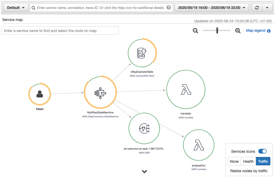
Trace map view: The trace map view shows in-depth information from a single trace as it moves through each service. Resources are listed in the order in which they are invoked.
Trace timeline: The trace timeline view shows the propagation of a trace through the workflow and is paired with a time scale called a latency distribution histogram. This shows how long it takes for a service to complete its requests. The trace is composed of segments and sub-segments. A segment represents the Step Functions execution. Subsegments each represent a state transition.

Getting Started

X-Ray tracing is enabled using AWS Serverless Application Model (AWS SAM), AWS CloudFormation or from within the AWS Management Console. To get started with Step Functions and X-Ray using the AWS Management Console:

  1. Go to the Step Functions page of the AWS Management Console.
  2. Choose Get Started, review the Hello World example, then choose Next.
  3. Check Enable X-Ray tracing from the Tracing section.

Workflow visibility

The following Step Functions workflow example is invoked via Amazon EventBridge when a new file is uploaded to an Amazon S3 bucket. The workflow uses Amazon Textract to detect text from an image file. It translates the text into multiple languages using Amazon Translate and saves the results into an Amazon DynamoDB table. X-Ray has been enabled for this workflow.

To view the X-Ray service map for this workflow, I choose the X-Ray trace map link at the top of the Step Functions Execution details page:

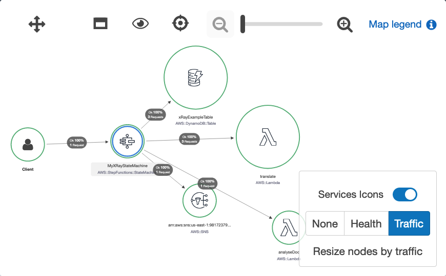
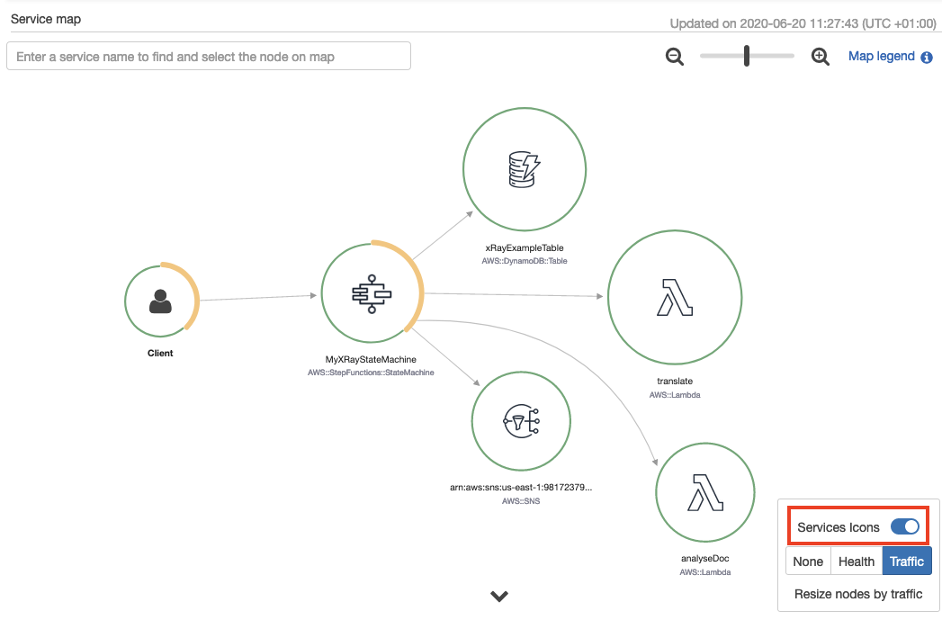
The service map is generated from trace data sent through the workflow. Toggling the Service Icons displays each individual service in this workload. The size of each node is weighted by traffic or health, depending on the selection.
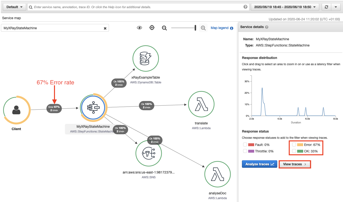
This shows the error percentage and average response times for each downstream service. T/min is the number of traces sent per minute in the selected time range. The following map shows a 67% error rate for the Step Functions workflow.
Accelerated troubleshooting

By drilling down through the service map, to the individual trace map, I quickly pinpoint the error in this workflow. I choose the Step Functions service from the trace map. This opens the service details panel. I then choose View traces. The trace data shows that from a group of nine responses, 3 completed successfully and 6 completed with error. This correlates with the response times listed for each individual trace. Three traces complete in over 5 seconds, while 6 took less than 3 seconds.
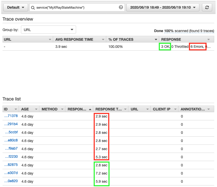
Choosing one of the faster traces opens the trace timeline map. This illustrates the aggregate response time for the workflow and each of its states. It shows a state named Read text from image invoked by a Lambda Function. This takes 2.3 seconds of the workflow’s total 2.9 seconds to complete.

A warning icon indicates that an error has occurred in this Lambda function. Hovering the curser over the icon, reveals that the property “Blocks” is undefined. This shows that an error occurred within the Lambda function (no text was found within the image). The Lambda function did not have sufficient error handling to manage this error gracefully, so the workflow exited.

Here’s how that same state execution failure looks in the Step Functions Graph inspector.

Performance profiling

The visualizations provided in the service map are useful for estimating the average latency in a workflow, but issues are often indicated by statistical outliers. To help investigate these, the Response distribution graph shows a distribution of latencies for each state within a workflow, and its downstream services.

Latency is the amount of time between when a request starts and when it completes. It shows duration on the x-axis, and the percentage of requests that match each duration on the y-axis. Additional filters are applied to find traces by duration or status code. This helps to discover patterns and to identify specific cases and clients with issues at a given percentile.

Sampling

X-Ray applies a sampling algorithm to determine which requests to trace. A sampling rate of 100% is used for state machines with an execution rate of less than one per second. State machines running at a rate greater than one execution per second default to a 5% sampling rate. Configure the sampling rate to determine what percentage of traces to sample. Enable trace sampling with the AWS Command Line Interface (AWS CLI) using the CreateStateMachine and UpdateStateMachine APIs with the enable-Trace-Sampling attribute:

--enable-trace-sampling true

It can also be configured in the AWS Management Console.

Trace data retention and limits

X-Ray retains tracing data for up to 30 days with a single trace holding up to 7 days of execution data. The current minimum guaranteed trace size is 100Kb, which equates to approximately 80 state transitions.   The actual number of state transitions supported will depend on the upstream and downstream calls and duration of the workflow. When the trace size limit is reached, the trace cannot be updated with new segments or updates to existing segments. The traces that have reached the limit are indicated with a banner in the X-Ray console.

For a full service comparison of X-Ray trace data and Step Functions execution history, please refer to the documentation.

Conclusion

The Step Functions integration with X-Ray provides a single monitoring dashboard for workflows running at scale. It provides a high-level system overview of all workflow resources and the ability to drill down to view detailed timelines of workflow executions. You can now use the orchestration capabilities of Step Functions with the tracing, visualization, and debug capabilities of AWS X-Ray.

This enables developers to reduce problem resolution times by visually identifying errors in resources and viewing error rates across workflow executions. You can profile and improve application performance by identifying outliers while analyzing and debugging high latency and jitter in workflow executions.

This feature is available in all Regions where both AWS Step Functions and AWS X-Ray are available. View the AWS Regions table to learn more. For pricing information, see AWS X-Ray pricing.

To learn more about Step Functions, read the Developer Guide. For more serverless learning resources, visit https://serverlessland.com.
Uploading to Amazon S3 directly from a web or mobile application

Post Syndicated from James Beswick original https://aws.amazon.com/blogs/compute/uploading-to-amazon-s3-directly-from-a-web-or-mobile-application/

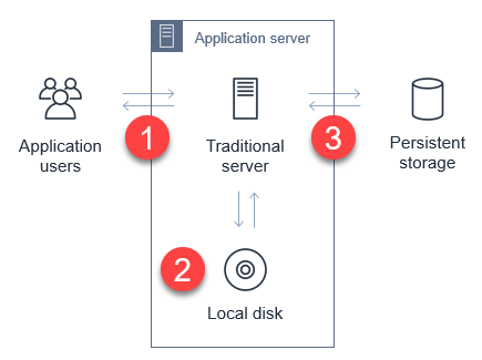
In web and mobile applications, it’s common to provide users with the ability to upload data. Your application may allow users to upload PDFs and documents, or media such as photos or videos. Every modern web server technology has mechanisms to allow this functionality. Typically, in the server-based environment, the process follows this flow:

Application server upload process

  1. The user uploads the file to the application server.
  2. The application server saves the upload to a temporary space for processing.
  3. The application transfers the file to a database, file server, or object store for persistent storage.

While the process is simple, it can have significant side-effects on the performance of the web-server in busier applications. Media uploads are typically large, so transferring these can represent a large share of network I/O and server CPU time. You must also manage the state of the transfer to ensure that the entire object is successfully uploaded, and manage retries and errors.

This is challenging for applications with spiky traffic patterns. For example, in a web application that specializes in sending holiday greetings, it may experience most traffic only around holidays. If thousands of users attempt to upload media around the same time, this requires you to scale out the application server and ensure that there is sufficient network bandwidth available.

By directly uploading these files to Amazon S3, you can avoid proxying these requests through your application server. This can significantly reduce network traffic and server CPU usage, and enable your application server to handle other requests during busy periods. S3 also is highly available and durable, making it an ideal persistent store for user uploads.

In this blog post, I walk through how to implement serverless uploads and show the benefits of this approach. This pattern is used in the Happy Path web application. You can download the code from this blog post in this GitHub repo.

Overview of serverless uploading to S3

When you upload directly to an S3 bucket, you must first request a signed URL from the Amazon S3 service. You can then upload directly using the signed URL. This is two-step process for your application front end:

Serverless uploading to S3

  1. Call an Amazon API Gateway endpoint, which invokes the getSignedURL Lambda function. This gets a signed URL from the S3 bucket.
  2. Directly upload the file from the application to the S3 bucket.

To deploy the S3 uploader example in your AWS account:

  1. Navigate to the S3 uploader repo and install the prerequisites listed in the README.md.
  2. In a terminal window, run:
    git clone https://github.com/aws-samples/amazon-s3-presigned-urls-aws-sam
    cd amazon-s3-presigned-urls-aws-sam
    sam deploy --guided
  3. At the prompts, enter s3uploader for Stack Name and select your preferred Region. Once the deployment is complete, note the APIendpoint output.

CloudFormation stack outputs

Testing the application

I show two ways to test this application. The first is with Postman, which allows you to directly call the API and upload a binary file with the signed URL. The second is with a basic frontend application that demonstrates how to integrate the API.

To test using Postman:

  1. First, copy the API endpoint from the output of the deployment.
  2. In the Postman interface, paste the API endpoint into the box labeled Enter request URL.
  3. Choose Send.Postman test
  4. After the request is complete, the Body section shows a JSON response. The uploadURL attribute contains the signed URL. Copy this attribute to the clipboard.
  5. Select the + icon next to the tabs to create a new request.
  6. Using the dropdown, change the method from GET to PUT. Paste the URL into the Enter request URL box.
  7. Choose the Body tab, then the binary radio button.Select the binary radio button in Postman
  8. Choose Select file and choose a JPG file to upload.
    Choose Send. You see a 200 OK response after the file is uploaded.200 response code in Postman
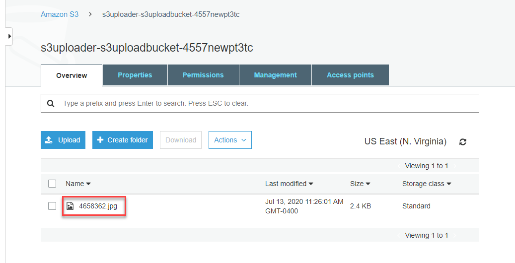
  9. Navigate to the S3 console, and open the S3 bucket created by the deployment. In the bucket, you see the JPG file uploaded via Postman.Uploaded object in S3 bucket

To test with the sample frontend application:

  1. Copy index.html from the example’s repo to an S3 bucket.
  2. Update the object’s permissions to make it publicly readable.
  3. In a browser, navigate to the public URL of index.html file.Frontend testing app at index.html
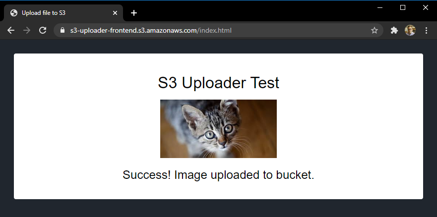
  4. Select Choose file and then select a JPG file to upload in the file picker. Choose Upload image. When the upload completes, a confirmation message is displayed.Upload in the test app
  5. Navigate to the S3 console, and open the S3 bucket created by the deployment. In the bucket, you see the second JPG file you uploaded from the browser.Second uploaded file in S3 bucket

Understanding the S3 uploading process

When uploading objects to S3 from a web application, you must configure S3 for Cross-Origin Resource Sharing (CORS). CORS rules are defined as an XML document on the bucket. Using AWS SAM, you can configure CORS as part of the resource definition in the AWS SAM template:

   S3UploadBucket:
    Type: AWS::S3::Bucket
    Properties:
      CorsConfiguration:
        CorsRules:
        - AllowedHeaders:
            - "*"
          AllowedMethods:
            - GET
            - PUT
            - HEAD
          AllowedOrigins:
            - "*"

The preceding policy allows all headers and origins – it’s recommended that you use a more restrictive policy for production workloads.

In the first step of the process, the API endpoint invokes the Lambda function to make the signed URL request. The Lambda function contains the following code:

const AWS = require('aws-sdk')
AWS.config.update({ region: process.env.AWS_REGION })
const s3 = new AWS.S3()
const URL_EXPIRATION_SECONDS = 300

// Main Lambda entry point
exports.handler = async (event) => {
  return await getUploadURL(event)
}

const getUploadURL = async function(event) {
  const randomID = parseInt(Math.random() * 10000000)
  const Key = `${randomID}.jpg`

  // Get signed URL from S3
  const s3Params = {
    Bucket: process.env.UploadBucket,
    Key,
    Expires: URL_EXPIRATION_SECONDS,
    ContentType: 'image/jpeg'
  }
  const uploadURL = await s3.getSignedUrlPromise('putObject', s3Params)
  return JSON.stringify({
    uploadURL: uploadURL,
    Key
  })
}

This function determines the name, or key, of the uploaded object, using a random number. The s3Params object defines the accepted content type and also specifies the expiration of the key. In this case, the key is valid for 300 seconds. The signed URL is returned as part of a JSON object including the key for the calling application.

The signed URL contains a security token with permissions to upload this single object to this bucket. To successfully generate this token, the code calling getSignedUrlPromise must have s3:putObject permissions for the bucket. This Lambda function is granted the S3WritePolicy policy to the bucket by the AWS SAM template.

The uploaded object must match the same file name and content type as defined in the parameters. An object matching the parameters may be uploaded multiple times, providing that the upload process starts before the token expires. The default expiration is 15 minutes but you may want to specify shorter expirations depending upon your use case.

Once the frontend application receives the API endpoint response, it has the signed URL. The frontend application then uses the PUT method to upload binary data directly to the signed URL:

let blobData = new Blob([new Uint8Array(array)], {type: 'image/jpeg'})
const result = await fetch(signedURL, {
  method: 'PUT',
  body: blobData
})

At this point, the caller application is interacting directly with the S3 service and not with your API endpoint or Lambda function. S3 returns a 200 HTML status code once the upload is complete.

For applications expecting a large number of user uploads, this provides a simple way to offload a large amount of network traffic to S3, away from your backend infrastructure.

Adding authentication to the upload process

The current API endpoint is open, available to any service on the internet. This means that anyone can upload a JPG file once they receive the signed URL. In most production systems, developers want to use authentication to control who has access to the API, and who can upload files to your S3 buckets.

You can restrict access to this API by using an authorizer. This sample uses HTTP APIs, which support JWT authorizers. This allows you to control access to the API via an identity provider, which could be a service such as Amazon Cognito or Auth0.

The Happy Path application only allows signed-in users to upload files, using Auth0 as the identity provider. The sample repo contains a second AWS SAM template, templateWithAuth.yaml, which shows how you can add an authorizer to the API:

  MyApi:
    Type: AWS::Serverless::HttpApi
    Properties:
      Auth:
        Authorizers:
          MyAuthorizer:
            JwtConfiguration:
              issuer: !Ref Auth0issuer
              audience:
                - https://auth0-jwt-authorizer
            IdentitySource: "$request.header.Authorization"
        DefaultAuthorizer: MyAuthorizer

Both the issuer and audience attributes are provided by the Auth0 configuration. By specifying this authorizer as the default authorizer, it is used automatically for all routes using this API. Read part 1 of the Ask Around Me series to learn more about configuring Auth0 and authorizers with HTTP APIs.

After authentication is added, the calling web application provides a JWT token in the headers of the request:

const response = await axios.get(API_ENDPOINT_URL, {
  headers: {
    Authorization: `Bearer ${token}`
        }
})

API Gateway evaluates this token before invoking the getUploadURL Lambda function. This ensures that only authenticated users can upload objects to the S3 bucket.

Modifying ACLs and creating publicly readable objects

In the current implementation, the uploaded object is not publicly accessible. To make an uploaded object publicly readable, you must set its access control list (ACL). There are preconfigured ACLs available in S3, including a public-read option, which makes an object readable by anyone on the internet. Set the appropriate ACL in the params object before calling s3.getSignedUrl:

const s3Params = {
  Bucket: process.env.UploadBucket,
  Key,
  Expires: URL_EXPIRATION_SECONDS,
  ContentType: 'image/jpeg',
  ACL: 'public-read'
}

Since the Lambda function must have the appropriate bucket permissions to sign the request, you must also ensure that the function has PutObjectAcl permission. In AWS SAM, you can add the permission to the Lambda function with this policy:

        - Statement:
          - Effect: Allow
            Resource: !Sub 'arn:aws:s3:::${S3UploadBucket}/'
            Action:
              - s3:putObjectAcl

Conclusion

Many web and mobile applications allow users to upload data, including large media files like images and videos. In a traditional server-based application, this can create heavy load on the application server, and also use a considerable amount of network bandwidth.

By enabling users to upload files to Amazon S3, this serverless pattern moves the network load away from your service. This can make your application much more scalable, and capable of handling spiky traffic.

This blog post walks through a sample application repo and explains the process for retrieving a signed URL from S3. It explains how to the test the URLs in both Postman and in a web application. Finally, I explain how to add authentication and make uploaded objects publicly accessible.

To learn more, see this video walkthrough that shows how to upload directly to S3 from a frontend web application. For more serverless learning resources, visit https://serverlessland.com.

Using Lambda layers to simplify your development process

Post Syndicated from James Beswick original https://aws.amazon.com/blogs/compute/using-lambda-layers-to-simplify-your-development-process/

Serverless developers frequently import libraries and dependencies into their AWS Lambda functions. While you can zip these dependencies as part of the build and deployment process, in many cases it’s easier to use layers instead. In this post, I explain how layers work, and how you can build and include layers in your own applications.

This blog post references the Happy Path application, which shows how to build a flexible backend to a photo-processing web application. To learn more, refer to Using serverless backends to iterate quickly on web apps – part 1. This code in this post is available at this GitHub repo.

Overview of Lambda layers

A Lambda layer is an archive containing additional code, such as libraries, dependencies, or even custom runtimes. When you include a layer in a function, the contents are extracted to the /opt directory in the execution environment. You can include up to five layers per function, which count towards the standard Lambda deployment size limits.

Layers are deployed as immutable versions, and the version number increments each time you publish a new layer. When you include a layer in a function, you specify the layer version you want to use. Layers are automatically set as private, but they can be shared with other AWS accounts, or shared publicly. Permissions only apply to a single version of a layer.

Using layers can make it faster to deploy applications with the AWS Serverless Application Model (AWS SAM) or the Serverless framework. By moving runtime dependencies from your function code to a layer, this can help reduce the overall size of the archive uploaded during a deployment.

Creating a layer containing the AWS SDK

The AWS SDK allows you to interact programmatically with AWS services using one of the supported runtimes. The Lambda service includes the AWS SDK so you can use it without explicitly importing in your deployment package.

However, there is no guarantee of the version provided in the execution environment. The SDK is upgraded frequently to support new AWS services and features. As a result, the version may change at any time. You can see the current version used by Lambda by declaring an instance of the SDK and logging out the version method:

Logging out the version method

For production workloads, it’s best practice to lock the version of the AWS SDK used in your functions. You can achieve this by including the SDK with your code package. Once you include this library, your code always uses the version in the deployment package and not the version included in the Lambda service.

A serverless application may consist of many functions, which all use a common SDK version. Instead of bundling the SDK with each function deployment, you can create a layer containing the SDK. The effect of this is to reduce the size of the uploaded archive, which makes your deployments faster.

To create an AWS SDK layer:

  1. First, clone this blog post’s GitHub repo. From a terminal window, execute:
    git clone https://github.com/aws-samples/aws-lambda-layers-aws-sam-examples
    cd ./aws-sdk-layer
  2. This directory contains an AWS SAM template and Node.js package.json file. Install the package.json contents:
    npm install
  3. Create the layer directory defined in the AWS SAM template and the nodejs directory required by Lambda. Next, move the node_modules directory:
    mkdir -p ./layer/nodejs
    mv ./node_modules ./layer/nodejs
  4. Next, deploy the AWS SAM template to create the layer:
    sam deploy --guided
  5. For the Stack name, enter “aws-sdk-layer”. Enter your preferred AWS Region and accept the other defaults.
  6. After the deployment completes, the new Lambda layer is available to use. Run this command to see the available layers:aws lambda list-layersaws lambda list-layers output

After adding a layer to a function, you can use console.log to log out the AWS SDK version. This shows that the function is now using the SDK version in the layer instead of the version provided by the Lambda service:

Use the SDK layer instead of the bundled layer

Creating layers with OS-specific binaries

Many code libraries include binaries that are operating-system specific. When you build packages on your local development machine, by default the binaries for that operating system are used. These may not be the right binaries for Lambda, which runs on Amazon Linux. If you are not using a compatible operating system, you must ensure you include Linux binaries in the layer.

The simplest way to package these libraries correctly is to use AWS Cloud9. This is an IDE in the AWS Cloud, which runs on Amazon EC2. After creating an environment, you can clone a git repository directly to the local storage of the instance, and run the necessary build scripts.

The Happy Path application resizes images using the Sharp npm library. This library uses libvips, which is written in C, so the compilation is operating system-specific. By creating a layer containing this library, it simplifies the packaging and deployment of the consuming Lambda function.

To create a Sharp layer using AWS Cloud9:

  1. Navigate to the AWS Cloud9 console.
  2. Choose Create environment.
  3. Enter the name “My IDE” and choose Next step.
  4. Accept all the default and choose Next step.
  5. Review the settings and choose Create environment.
  6. In the terminal panel, enter:
    git clone https://github.com/aws-samples/aws-lambda-layers-aws-sam-examples
    cd ./aws-lambda-layers-aws-sam-examples/sharp-layer
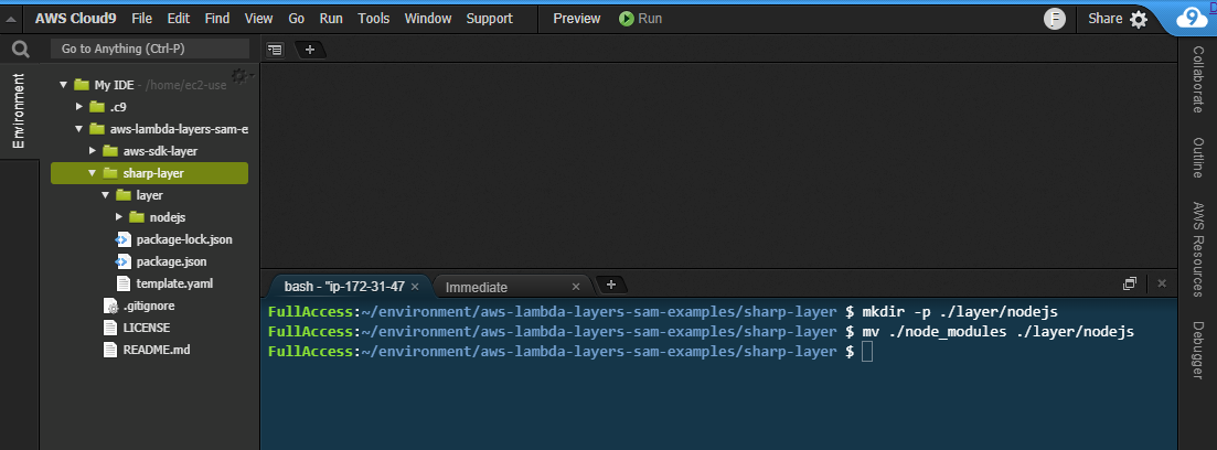
    npm installCreating a layer in Cloud9
  7. From a terminal window, ensure you are in the directory where you cloned this post’s GitHub repo. Execute the following commands:cd ./sharp-layer
    npm install
    mkdir -p ./layer/nodejs
    mv ./node_modules ./layer/nodejsCreating the layer in Cloud9
  8. Next, deploy the AWS SAM template to create the layer:
    sam deploy --guided
  9. For the Stack name, enter “sharp-layer”. Enter your preferred AWS Region and accept the other defaults. After the deployment completes, the new Lambda layer is available to use.

In some runtimes, you can specify a local set of packages for development, and another set for production. For example, in Node.js, the package.json file allows you to specify two sections for dependencies. If your development machine uses a different operating system to Lambda, and therefore uses different binaries, you can use package.json to resolve this. In the Happy Path Resizer function, which uses the Sharp layer, the package.json refers to a local binary for development.

Adding development dependencies to package.json

AWS SAM defines Lambda functions with the AWS::Serverless::Function resource. Layers are defined as a property of functions, as a list of layer ARNs including the version:

  MyLambdaFunction:
    Type: AWS::Serverless::Function 
    Properties:
      CodeUri: myFunction/
      Handler: app.handler
      MemorySize: 128
      Layers:
        - !Ref SharpLayerARN

Sharing a layer

Layers are private to your account by default but you can optionally share with other AWS accounts or make a layer public. You cannot share layers via the AWS Management Console but instead use the AWS CLI.

To share a layer, use add-layer-version-permission, specifying the layer name, version, AWS Region, and principal:

aws lambda add-layer-version-permission \
  --layer-name node-sharp \
  --principal '*' \
  --action lambda:GetLayerVersion \
  --version-number 3 
  --statement-id public 
  --region us-east-1

In the principal parameter, specify an individual account ID or use an asterisk to make the layer public. The CLI responds with a RevisionId containing the current revision of the policy:

add-layer-version output

You can check the permissions associated with a layer version by calling get-layer-version-policy with the layer name and version:

aws lambda get-layer-version-policy \
  --layer-name node-sharp \
  --version-number 3 \
  --region us-east-1

get-layer-version-policy output

Similarly, you can delete permissions associated with a layer version by calling remove-layer-vesion-permission with the layer name, statement ID, and version:

aws lambda remove-layer-version-permission \
 -- layer-name node-sharp \
 -- statement-id public \
 -- version-number 3

Once the permissions are removed, calling get-layer-version-policy results in an error:

Error invoking after removal

Conclusion

Lambda layers provide a convenient and effective way to package code libraries for sharing with Lambda functions in your account. Using layers can help reduce the size of uploaded archives and make it faster to deploy your code.

Layers can contain packages using OS-specific binaries, providing a convenient way to distribute these to developers. While layers are private by default, you can share with other accounts or make a layer public. Layers are published as immutable versions, and deleting a layer has no effect on deployed Lambda functions already using that layer.

To learn more about using Lambda layers, visit the documentation, or see how layers are used in the Happy Path web application.

Troubleshooting Amazon API Gateway with enhanced observability variables

Post Syndicated from Eric Johnson original https://aws.amazon.com/blogs/compute/troubleshooting-amazon-api-gateway-with-enhanced-observability-variables/

Amazon API Gateway is often used for managing access to serverless applications. Additionally, it can help developers reduce code and increase security with features like AWS WAF integration and authorizers at the API level.

Because more is handled by API Gateway, developers tell us they would like to see more data points on the individual parts of the request. This data helps developers understand each phase of the API request and how it affects the request as a whole. In response to this request, the API Gateway team has added new enhanced observability variables to the API Gateway access logs. With these new variables, developers can troubleshoot on a more granular level to quickly isolate and resolve request errors and latency issues.

The phases of an API request

API Gateway divides requests into phases, reflected by the variables that have been added. Depending upon the features configured for the application, an API request goes through multiple phases. The phases appear in a specific order as follows:

Phases of an API request

Phases of an API request

  • WAF: the WAF phase only appears when an AWS WAF web access control list (ACL) is configured for enhanced security. During this phase, WAF rules are evaluated and a decision is made on whether to continue or cancel the request.
  • Authenticate: the authenticate phase is only present when AWS Identity and Access Management (IAM) authorizers are used. During this phase, the credentials of the signed request are verified. Access is granted or denied based on the client’s right to assume the access role.
  • Authorizer: the authorizer phase is only present when a Lambda, JWT, or Amazon Cognito authorizer is used. During this phase, the authorizer logic is processed to verify the user’s right to access the resource.
  • Authorize: the authorize phase is only present when a Lambda or IAM authorizer is used. During this phase, the results from the authenticate and authorizer phase are evaluated and applied.
  • Integration: during this phase, the backend integration processes the request.

Each phrase can add latency to the request, return a status, or raise an error. To capture this data, API Gateway now provides enhanced observability variables based on each phase. The variables are named according to the phase they occur in and follow the naming structure, $context.phase.property. Therefore, you can get data about WAF latency by using $context.waf.latency.

Some existing variables have also been given aliases to match this naming schema. For example, $context.integrationErrorMessage has a new alias of $context.integration.error. The resulting list of variables is as follows:

Phases and variables for API Gateway requests

Phases and variables for API Gateway requests

API Gateway provides status, latency, and error data for each phase. In the authorizer and integration phases, there are additional variables you can use in logs. The $context.phase.requestId provides the request ID from that service and the $context.phase.integrationStatus provide the status code.

For example, when using an AWS Lambda function as the integration, API Gateway receives two status codes. The first, $context.integration.integrationStatus, is the status of the Lambda service itself. This is usually 200, unless there is a service or permissions error. The second, $context.integration.status, is the status of the Lambda function and reports on the success or failure of the code.

A full list of access log variables is in the documentation for REST APIs, WebSocket APIs, and HTTP APIs.

A troubleshooting example

In this example, an application is built using an API Gateway REST API with a Lambda function for the backend integration. The application uses an IAM authorizer to require AWS account credentials for application access. The application also uses an AWS WAF ACL to rate limit requests to 100 requests per IP, per five minutes. The demo application and deployment instructions can be found in the Sessions With SAM repository.

Because the application involves an AWS WAF and IAM authorizer for security, the request passes through four phases: waf, authenticate, authorize, and integration. The access log format is configured to capture all the data regarding these phases:

{
  "requestId":"$context.requestId",
  "waf-error":"$context.waf.error",
  "waf-status":"$context.waf.status",
  "waf-latency":"$context.waf.latency",
  "waf-response":"$context.wafResponseCode",
  "authenticate-error":"$context.authenticate.error",
  "authenticate-status":"$context.authenticate.status",
  "authenticate-latency":"$context.authenticate.latency",
  "authorize-error":"$context.authorize.error",
  "authorize-status":"$context.authorize.status",
  "authorize-latency":"$context.authorize.latency",
  "integration-error":"$context.integration.error",
  "integration-status":"$context.integration.status",
  "integration-latency":"$context.integration.latency",
  "integration-requestId":"$context.integration.requestId",
  "integration-integrationStatus":"$context.integration.integrationStatus",
  "response-latency":"$context.responseLatency",
  "status":"$context.status"
}

Once the application is deployed, use Postman to test the API with a sigV4 request.

Configuring Postman authorization

Configuring Postman authorization

To show troubleshooting with the new enhanced observability variables, the first request sent through contains invalid credentials. The user receives a 403 Forbidden error.

Client response view with invalid tokens

Client response view with invalid tokens

The access log for this request is:

{
    "requestId": "70aa9606-26be-4396-991c-405a3671fd9a",
    "waf-error": "-",
    "waf-status": "200",
    "waf-latency": "8",
    "waf-response": "WAF_ALLOW",
    "authenticate-error": "-",
    "authenticate-status": "403",
    "authenticate-latency": "17",
    "authorize-error": "-",
    "authorize-status": "-",
    "authorize-latency": "-",
    "integration-error": "-",
    "integration-status": "-",
    "integration-latency": "-",
    "integration-requestId": "-",
    "integration-integrationStatus": "-",
    "response-latency": "48",
    "status": "403"
}

The request passed through the waf phase first. Since this is the first request and the rate limit has not been exceeded, the request is passed on to the next phase, authenticate. During the authenticate phase, the user’s credentials are verified. In this case, the credentials are invalid and the request is rejected with a 403 response before invoking the downstream phases.

To correct this, the next request uses valid credentials, but those credentials do not have access to invoke the API. Again, the user receives a 403 Forbidden error.

Client response view with unauthorized tokens

Client response view with unauthorized tokens

The access log for this request is:

{
  "requestId": "c16d9edc-037d-4f42-adf3-eaadf358db2d",
  "waf-error": "-",
  "waf-status": "200",
  "waf-latency": "7",
  "waf-response": "WAF_ALLOW",
  "authenticate-error": "-",
  "authenticate-status": "200",
  "authenticate-latency": "8",
  "authorize-error": "The client is not authorized to perform this operation.",
  "authorize-status": "403",
  "authorize-latency": "0",
  "integration-error": "-",
  "integration-status": "-",
  "integration-latency": "-",
  "integration-requestId": "-",
  "integration-integrationStatus": "-",
  "response-latency": "52",
  "status": "403"
}

This time, the access logs show that the authenticate phase returns a 200. This indicates that the user credentials are valid for this account. However, the authorize phase returns a 403 and states, “The client is not authorized to perform this operation”. Again, the request is rejected with a 403 response before invoking downstream phases.

The last request for the API contains valid credentials for a user that has rights to invoke this API. This time the user receives a 200 OK response and the requested data.

Client response view with valid request

Client response view with valid request

The log for this request is:

{
  "requestId": "ac726ce5-91dd-4f1d-8f34-fcc4ae0bd622",
  "waf-error": "-",
  "waf-status": "200",
  "waf-latency": "7",
  "waf-response": "WAF_ALLOW",
  "authenticate-error": "-",
  "authenticate-status": "200",
  "authenticate-latency": "1",
  "authorize-error": "-",
  "authorize-status": "200",
  "authorize-latency": "0",
  "integration-error": "-",
  "integration-status": "200",
  "integration-latency": "16",
  "integration-requestId": "8dc58335-fa13-4d48-8f99-2b1c97f41a3e",
  "integration-integrationStatus": "200",
  "response-latency": "48",
  "status": "200"
}

This log contains a 200 status code from each of the phases and returns a 200 response to the user. Additionally, each of the phases reports latency. This request had a total of 48 ms of latency. The latency breaks down according to the following:

Request latency breakdown

Request latency breakdown

Developers can use this information to identify the cause of latency within the API request and adjust accordingly. While some phases like authenticate or authorize are immutable, optimizing the integration phase of this request could remove a large chunk of the latency involved.

Conclusion

This post covers the enhanced observability variables, the phases they occur in, and the order of those phases. With these new variables, developers can quickly isolate the problem and focus on resolving issues.

When configured with the proper access logging variables, API Gateway access logs can provide a detailed story of API performance. They can help developers to continually optimize that performance. To learn how to configure logging in API Gateway with AWS SAM, see the demonstration app for this blog.

#ServerlessForEveryone

Building a serverless document scanner using Amazon Textract and AWS Amplify

Post Syndicated from Moheeb Zara original https://aws.amazon.com/blogs/compute/building-a-serverless-document-scanner-using-amazon-textract-and-aws-amplify/

This guide demonstrates creating and deploying a production ready document scanning application. It allows users to manage projects, upload images, and generate a PDF from detected text. The sample can be used as a template for building expense tracking applications, handling forms and legal documents, or for digitizing books and notes.

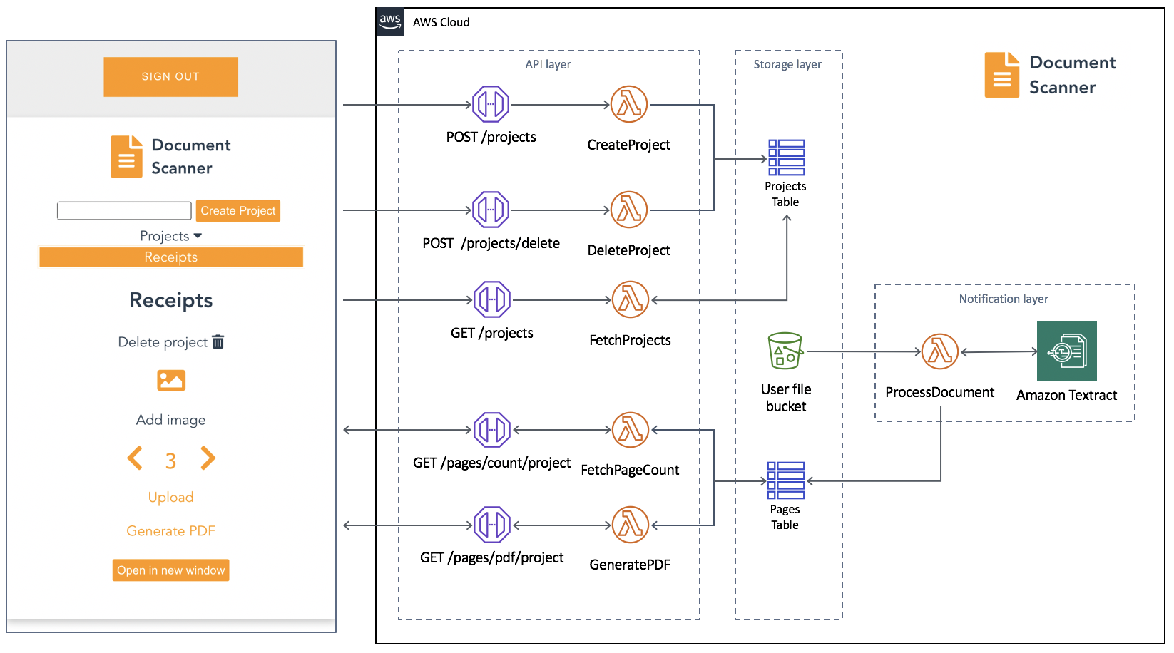
The frontend application is written in Vue.js and uses the Amplify Framework. The backend is built using AWS serverless technologies and consists of an Amazon API Gateway REST API that invokes AWS Lambda functions. Amazon Textract is used to analyze text from uploaded images to an Amazon S3 bucket. Detected text is stored in Amazon DynamoDB.

An architectural diagram of the application.

An architectural diagram of the application.

Prerequisites

You need the following to complete the project:

Deploy the application

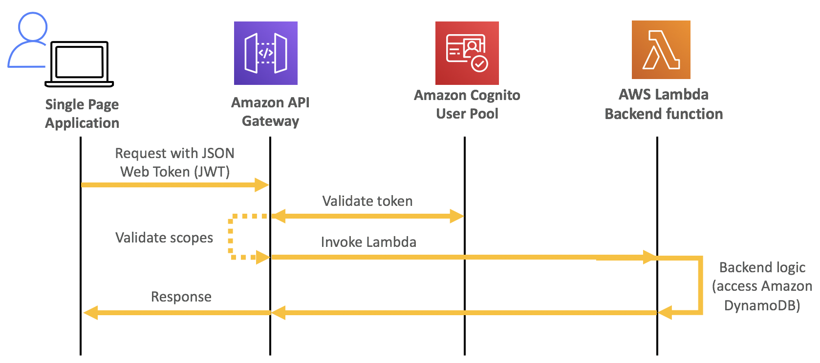
The solution consists of two parts, the frontend application and the serverless backend. The Amplify CLI deploys all the Amazon Cognito authentication, and hosting resources for the frontend. The backend requires the Amazon Cognito user pool identifier to configure an authorizer on the API. This enables an authorization workflow, as shown in the following image.

A diagram showing how an Amazon Cognito authorization workflow works

A diagram showing how an Amazon Cognito authorization workflow works

First, configure the frontend. Complete the following steps using a terminal running on a computer or by using the AWS Cloud9 IDE. If using AWS Cloud9, create an instance using the default options.

From the terminal:

  1. Install the Amplify CLI by running this command.
    npm install -g @aws-amplify/cli
  2. Configure the Amplify CLI using this command. Follow the guided process to completion.
    amplify configure
  3. Clone the project from GitHub.
    git clone https://github.com/aws-samples/aws-serverless-document-scanner.git
  4. Navigate to the amplify-frontend directory and initialize the project using the Amplify CLI command. Follow the guided process to completion.
    cd aws-serverless-document-scanner/amplify-frontend
    
    amplify init
  5. Deploy all the frontend resources to the AWS Cloud using the Amplify CLI command.
    amplify push
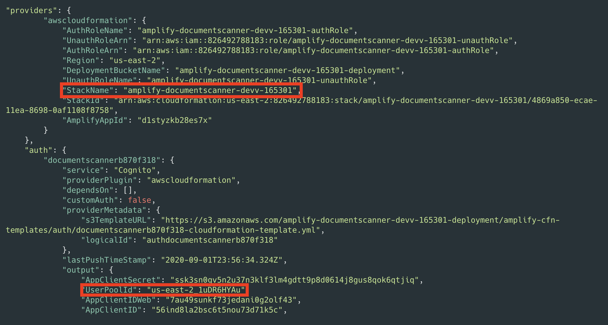
  6. After the resources have finishing deploying, make note of the StackName and UserPoolId properties in the amplify-frontend/amplify/backend/amplify-meta.json file. These are required when deploying the serverless backend.

Next, deploy the serverless backend. While it can be deployed using the AWS SAM CLI, you can also deploy from the AWS Management Console:

  1. Navigate to the document-scanner application in the AWS Serverless Application Repository.
  2. In Application settings, name the application and provide the StackName and UserPoolId from the frontend application for the UserPoolID and AmplifyStackName parameters. Provide a unique name for the BucketName parameter.
  3. Choose Deploy.
  4. Once complete, copy the API endpoint so that it can be configured on the frontend application in the next section.

Configure and run the frontend application

  1. Create a file, amplify-frontend/src/api-config.js, in the frontend application with the following content. Include the API endpoint and the unique BucketName from the previous step. The s3_region value must be the same as the Region where your serverless backend is deployed.
    const apiConfig = {
    	"endpoint": "<API ENDPOINT>",
    	"s3_bucket_name": "<BucketName>",
    	"s3_region": "<Bucket Region>"
    };
    
    export default apiConfig;
  2. In a terminal, navigate to the root directory of the frontend application and run it locally for testing.
    cd aws-serverless-document-scanner/amplify-frontend
    
    npm install
    
    npm run serve

    You should see an output like this:

  3. To publish the frontend application to cloud hosting, run the following command.
    amplify publish

    Once complete, a URL to the hosted application is provided.

Using the frontend application

Once the application is running locally or hosted in the cloud, navigating to it presents a user login interface with an option to register. The registration flow requires a code sent to the provided email for verification. Once verified you’re presented with the main application interface.

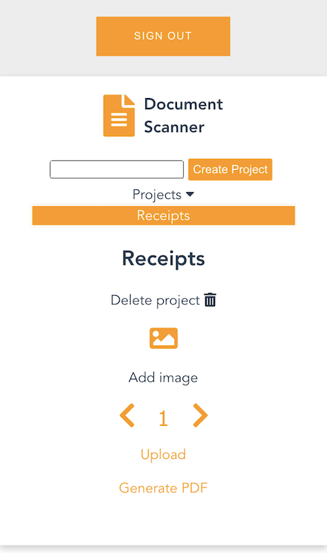
Once you create a project and choose it from the list, you are presented with an interface for uploading images by page number.

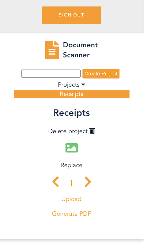
On mobile, it uses the device camera to capture images. On desktop, images are provided by the file system. You can replace an image and the page selector also lets you go back and change an image. The corresponding analyzed text is updated in DynamoDB as well.
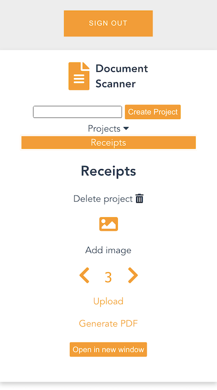
Each time you upload an image, the page is incremented. Choosing “Generate PDF” calls the endpoint for the GeneratePDF Lambda function and returns a PDF in base64 format. The download begins automatically.

You can also open the PDF in another window, if viewing a preview in a desktop browser.

Understanding the serverless backend

An architecture diagram of the serverless backend.

An architecture diagram of the serverless backend.

In the GitHub project, the folder serverless-backend/ contains the AWS SAM template file and the Lambda functions. It creates an API Gateway endpoint, six Lambda functions, an S3 bucket, and two DynamoDB tables. The template also defines an Amazon Cognito authorizer for the API using the UserPoolID passed in as a parameter:

Parameters:
  UserPoolID:
    Type: String
    Description: (Required) The user pool ID created by the Amplify frontend.

  AmplifyStackName:
    Type: String
    Description: (Required) The stack name of the Amplify backend deployment. 

  BucketName:
    Type: String
    Default: "ds-userfilebucket"
    Description: (Required) A unique name for the user file bucket. Must be all lowercase.  


Globals:
  Api:
    Cors:
      AllowMethods: "'*'"
      AllowHeaders: "'*'"
      AllowOrigin: "'*'"

Resources:

  DocumentScannerAPI:
    Type: AWS::Serverless::Api
    Properties:
      StageName: Prod
      Auth:
        DefaultAuthorizer: CognitoAuthorizer
        Authorizers:
          CognitoAuthorizer:
            UserPoolArn: !Sub 'arn:aws:cognito-idp:${AWS::Region}:${AWS::AccountId}:userpool/${UserPoolID}'
            Identity:
              Header: Authorization
        AddDefaultAuthorizerToCorsPreflight: False

This only allows authenticated users of the frontend application to make requests with a JWT token containing their user name and email. The backend uses that information to fetch and store data in DynamoDB that corresponds to the user making the request.

Two DynamoDB tables are created. A Project table, which tracks all the project names by user, and a Pages table, which tracks pages by project and user. The DynamoDB tables are created by the AWS SAM template with the partition key and range key defined for each table. These are used by the Lambda functions to query and sort items. See the documentation to learn more about DynamoDB table key schema.

ProjectsTable:
    Type: AWS::DynamoDB::Table
    Properties: 
      AttributeDefinitions: 
        - 
          AttributeName: "username"
          AttributeType: "S"
        - 
          AttributeName: "project_name"
          AttributeType: "S"
      KeySchema: 
        - AttributeName: username
          KeyType: HASH
        - AttributeName: project_name
          KeyType: RANGE
      ProvisionedThroughput: 
        ReadCapacityUnits: "5"
        WriteCapacityUnits: "5"

  PagesTable:
    Type: AWS::DynamoDB::Table
    Properties: 
      AttributeDefinitions: 
        - 
          AttributeName: "project"
          AttributeType: "S"
        - 
          AttributeName: "page"
          AttributeType: "N"
      KeySchema: 
        - AttributeName: project
          KeyType: HASH
        - AttributeName: page
          KeyType: RANGE
      ProvisionedThroughput: 
        ReadCapacityUnits: "5"
        WriteCapacityUnits: "5"

When an API Gateway endpoint is called, it passes the user credentials in the request context to a Lambda function. This is used by the CreateProject Lambda function, which also receives a project name in the request body, to create an item in the Project Table and associate it with a user.

The endpoint for the FetchProjects Lambda function is called to retrieve the list of projects associated with a user. The DeleteProject Lambda function removes a specific project from the Project table and any associated pages in the Pages table. It also deletes the folder in the S3 bucket containing all images for the project.

When a user enters a Project, the API endpoint calls the FetchPageCount Lambda function. This returns the number of pages for a project to update the current page number in the upload selector. The project is retrieved from the path parameters, as defined in the AWS SAM template:

FetchPageCount:
    Type: AWS::Serverless::Function
    Properties:
      Handler: app.handler
      Runtime: python3.8
      CodeUri: lambda_functions/fetchPageCount/
      Policies:
        - DynamoDBCrudPolicy:
            TableName: !Ref PagesTable
      Environment:
        Variables:
          PAGES_TABLE_NAME: !Ref PagesTable
      Events:
        GetResource:
          Type: Api
          Properties:
            RestApiId: !Ref DocumentScannerAPI
            Path: /pages/count/{project+}
            Method: get  

The template creates an S3 bucket and two AWS IAM managed policies. The policies are applied to the AuthRole and UnauthRole created by Amplify. This allows users to upload images directly to the S3 bucket. To understand how Amplify works with Storage, see the documentation.

The template also sets an S3 event notification on the bucket for all object create events with a “.png” suffix. Whenever the frontend uploads an image to S3, the object create event invokes the ProcessDocument Lambda function.

The function parses the object key to get the project name, user, and page number. Amazon Textract then analyzes the text of the image. The object returned by Amazon Textract contains the detected text and detailed information, such as the positioning of text in the image. Only the raw lines of text are stored in the Pages table.

import os
import json, decimal
import boto3
import urllib.parse
from boto3.dynamodb.conditions import Key, Attr

client = boto3.resource('dynamodb')
textract = boto3.client('textract')

tableName = os.environ.get('PAGES_TABLE_NAME')

def handler(event, context):

  table = client.Table(tableName)

  print(table.table_status)
 
  key = urllib.parse.unquote(event['Records'][0]['s3']['object']['key'])
  bucket = event['Records'][0]['s3']['bucket']['name']
  project = key.split('/')[3]
  page = key.split('/')[4].split('.')[0]
  user = key.split('/')[2]
  
  response = textract.detect_document_text(
    Document={
        'S3Object': {
            'Bucket': bucket,
            'Name': key
        }
    })
    
  fullText = ""
  
  for item in response["Blocks"]:
    if item["BlockType"] == "LINE":
        fullText = fullText + item["Text"] + '\n'
  
  print(fullText)

  table.put_item(Item= {
    'project': user + '/' + project,
    'page': int(page), 
    'text': fullText
    })

  # print(response)
  return

The GeneratePDF Lambda function retrieves the detected text for each page in a project from the Pages table. It combines the text into a PDF and returns it as a base64-encoded string for download. This function can be modified if your document structure differs.

Understanding the frontend

In the GitHub repo, the folder amplify-frontend/src/ contains all the code for the frontend application. In main.js, the Amplify VueJS modules are configured to use the resources defined in aws-exports.js. It also configures the endpoint and S3 bucket of the serverless backend, defined in api-config.js.

In components/DocumentScanner.vue, the API module is imported and the API is defined.

API calls are defined as Vue methods that can be called by various other components and elements of the application.

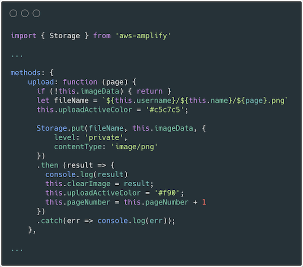
In components/Project.vue, the frontend uses the Storage module for Amplify to upload images. For more information on how to use S3 in an Amplify project see the documentation.

Conclusion

This blog post shows how to create a multiuser application that can analyze text from images and generate PDF documents. This guide demonstrates how to do so in a secure and scalable way using a serverless approach. The example also shows an event driven pattern for handling high volume image processing using S3, Lambda, and Amazon Textract.

The Amplify Framework simplifies the process of implementing authentication, storage, and backend integration. Explore the full solution on GitHub to modify it for your next project or startup idea.

To learn more about AWS serverless and keep up to date on the latest features, subscribe to the YouTube channel.

#ServerlessForEveryone

Jump-starting your serverless development environment

Post Syndicated from Benjamin Smith original https://aws.amazon.com/blogs/compute/jump-starting-your-serverless-development-environment/

Developers building serverless applications often wonder how they can jump-start their local development environment. This blog post provides a broad guide for those developers wanting to set up a development environment for building serverless applications.

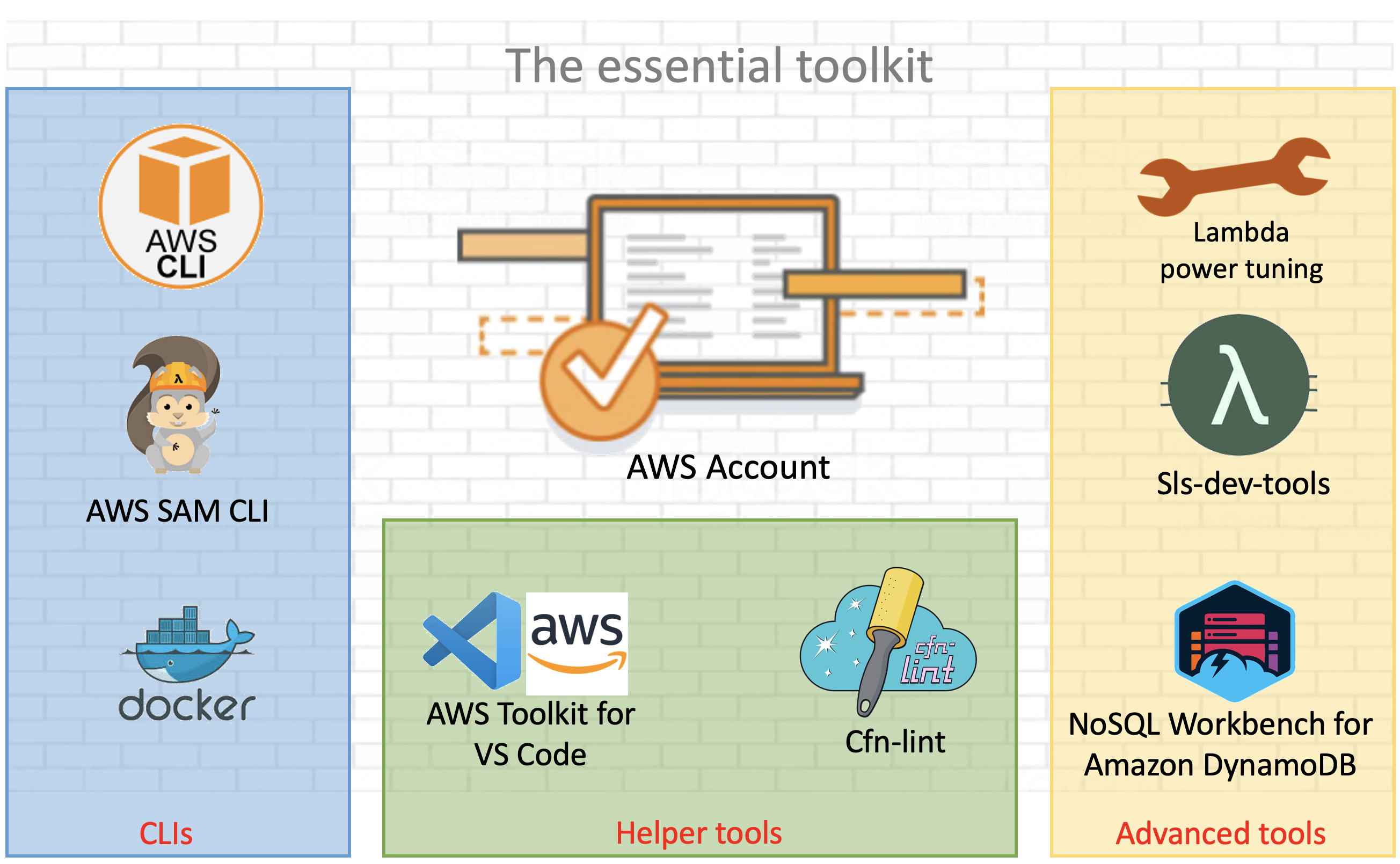
serverless development environment

AWS and open source tools for a serverless development environment .

To use AWS Lambda and other AWS services, create and activate an AWS account.

Command line tooling

Command line tools are scripts, programs, and libraries that enable rapid application development and interactions from within a command line shell.

The AWS CLI

The AWS Command Line Interface (AWS CLI) is an open source tool that enables developers to interact with AWS services using a command line shell. In many cases, the AWS CLI increases developer velocity for building cloud resources and enables automating repetitive tasks. It is an important piece of any serverless developer’s toolkit. Follow these instructions to install and configure the AWS CLI on your operating system.

AWS enables you to build infrastructure with code. This provides a single source of truth for AWS resources. It enables development teams to use version control and create deployment pipelines for their cloud infrastructure. AWS CloudFormation provides a common language to model and provision these application resources in your cloud environment.

AWS Serverless Application Model (AWS SAM CLI)

AWS Serverless Application Model (AWS SAM) is an extension for CloudFormation that further simplifies the process of building serverless application resources.

It provides shorthand syntax to define Lambda functions, APIs, databases, and event source mappings. During deployment, the AWS SAM syntax is transformed into AWS CloudFormation syntax, enabling you to build serverless applications faster.

The AWS SAM CLI is an open source command line tool used to locally build, test, debug, and deploy serverless applications defined with AWS SAM templates.

Install AWS SAM CLI on your operating system.

Test the installation by initializing a new quick start project with the following command:

$ sam init
  1. Choose 1 for the “Quick Start Templates”
  2. Choose 1 for the “Node.js runtime”
  3. Use the default name.

The generated /sam-app/template.yaml contains all the resource definitions for your serverless application. This includes a Lambda function with a REST API endpoint, along with the necessary IAM permissions.

Resources:
  HelloWorldFunction:
    Type: AWS::Serverless::Function # More info about Function Resource: https://github.com/awslabs/serverless-application-model/blob/master/versions/2016-10-31.md#awsserverlessfunction
    Properties:
      CodeUri: hello-world/
      Handler: app.lambdaHandler
      Runtime: nodejs12.x
      Events:
        HelloWorld:
          Type: Api # More info about API Event Source: https://github.com/awslabs/serverless-application-model/blob/master/versions/2016-10-31.md#api
          Properties:
            Path: /hello
            Method: get

Deploy this application using the AWS SAM CLI guided deploy:

$ sam deploy -g

Local testing with AWS SAM CLI

The AWS SAM CLI requires Docker containers to simulate the AWS Lambda runtime environment on your local development environment. To test locally, install Docker Engine and run the Lambda function with following command:

$ sam local invoke "HelloWorldFunction" -e events/event.json

The first time this function is invoked, Docker downloads the lambci/lambda:nodejs12.x container image. It then invokes the Lambda function with a pre-defined event JSON file.

Helper tools

There are a number of open source tools and packages available to help you monitor, author, and optimize your Lambda-based applications. Some of the most popular tools are shown in the following list.

Template validation tooling

CloudFormation Linter is a validation tool that helps with your CloudFormation development cycle. It analyses CloudFormation YAML and JSON templates to resolve and validate intrinsic functions and resource properties. By analyzing your templates before deploying them, you can save valuable development time and build automated validation into your deployment release cycle.

Follow these instructions to install the tool.

Once, installed, run the cfn-lint command with the path to your AWS SAM template provided as the first argument:

cfn-lint template.yaml
AWS SAM template validation with cfn-lint

AWS SAM template validation with cfn-lint

The following example shows that the template is not valid because the !GettAtt function does not evaluate correctly.

IDE tooling

Use AWS IDE plugins to author and invoke Lambda functions from within your existing integrated development environment (IDE). AWS IDE toolkits are available for PyCharm, IntelliJ. Visual Studio.

The AWS Toolkit for Visual Studio Code provides an integrated experience for developing serverless applications. It enables you to invoke Lambda functions, specify function configurations, locally debug, and deploy—all conveniently from within the editor. The toolkit supports Node.js, Python, and .NET.

The AWS Toolkit for Visual Studio Code

From Visual Studio Code, choose the Extensions icon on the Activity Bar. In the Search Extensions in Marketplace box, enter AWS Toolkit and then choose AWS Toolkit for Visual Studio Code as shown in the following example. This opens a new tab in the editor showing the toolkit’s installation page. Choose the Install button in the header to add the extension.

AWS Toolkit extension for Visual Studio Code

AWS Toolkit extension for Visual Studio Code

AWS Cloud9

Another option to build a development environment without having to install anything locally is to use AWS Cloud9. AWS Cloud9 is a cloud-based integrated development environment (IDE) for writing, running, and debugging code from within the browser.

It provides a seamless experience for developing serverless applications. It has a preconfigured development environment that includes AWS CLI, AWS SAM CLI, SDKs, code libraries, and many useful plugins. AWS Cloud9 also provides an environment for locally testing and debugging AWS Lambda functions. This eliminates the need to upload your code to the Lambda console. It allows developers to iterate on code directly, saving time, and improving code quality.

Follow this guide to set up AWS Cloud9 in your AWS environment.

Advanced tooling

Efficient configuration of Lambda functions is critical when expecting optimal cost and performance of your serverless applications. Lambda allows you to control the memory (RAM) allocation for each function.

Lambda charges based on the number of function requests and the duration, the time it takes for your code to run. The price for duration depends on the amount of RAM you allocate to your function. A smaller RAM allocation may reduce the performance of your application if your function is running compute-heavy workloads. If performance needs outweigh cost, you can increase the memory allocation.

Cost and performance optimization tooling

AWS Lambda power tuner is an open source tool that uses an AWS Step Functions state machine to suggest cost and performance optimizations for your Lambda functions. It invokes a given function with multiple memory configurations. It analyzes the execution log results to determine and suggest power configurations that minimize cost and maximize performance.

To deploy the tool:

  1. Clone the repository as follows:
    $ git clone https://github.com/alexcasalboni/aws-lambda-power-tuning.git
  2. Create an Amazon S3 bucket and enter the deployment configurations in /scripts/deploy.sh:
    # config
    BUCKET_NAME=your-sam-templates-bucket
    STACK_NAME=lambda-power-tuning
    PowerValues='128,512,1024,1536,3008'
  3. Run the deploy.sh script from your terminal, this uses the AWS SAM CLI to deploy the application:
    $ bash scripts/deploy.sh
  4. Run the power tuning tool from the terminal using the AWS CLI:
    aws stepfunctions start-execution \
    --state-machine-arn arn:aws:states:us-east-1:0123456789:stateMachine:powerTuningStateMachine-Vywm3ozPB6Am \
    --input "{\"lambdaARN\": \"arn:aws:lambda:us-east-1:1234567890:function:testytest\", \"powerValues\":[128,256,512,1024,2048],\"num\":50,\"payload\":{},\"parallelInvocation\":true,\"strategy\":\"cost\"}" \
    --output json
  5. The Step Functions execution output produces a link to a visual summary of the suggested results:

    AWS Lambda power tuning results

    AWS Lambda power tuning results

Monitoring and debugging tooling

Sls-dev-tools is an open source serverless tool that delivers serverless metrics directly to the terminal. It provides developers with feedback on their serverless application’s metrics and key bindings that deploy, open, and manipulate stack resources. Bringing this data directly to your terminal or IDE, reduces context switching between the developer environment and the web interfaces. This can increase application development speed and improve user experience.

Follow these instructions to install the tool onto your development environment.

To open the tool, run the following command:

$ Sls-dev-tools

Follow the in-terminal interface to choose which stack to monitor or edit.

The following example shows how the tool can be used to invoke a Lambda function with a custom payload from within the IDE.

Invoke an AWS Lambda function with a custom payload using sls-dev-tools

Invoke an AWS Lambda function with a custom payload using sls-dev-tools

Serverless database tooling

NoSQL Workbench for Amazon DynamoDB is a GUI application for modern database development and operations. It provides a visual IDE tool for data modeling and visualization with query development features to help build serverless applications with Amazon DynamoDB tables. Define data models using one or more tables and visualize the data model to see how it works in different scenarios. Run or simulate operations and generate the code for Python, JavaScript (Node.js), or Java.

Choose the correct operating system link to download and install NoSQL Workbench on your development machine.

The following example illustrates a connection to a DynamoDB table. A data scan is built using the GUI, with Node.js code generated for inclusion in a Lambda function:

Connecting to an Amazon DynamoBD table with NoSQL Workbench for AmazonDynamoDB

Connecting to an Amazon DynamoDB table with NoSQL Workbench for Amazon DynamoDB

Generating query code with NoSQL Workbench for Amazon DynamoDB

Generating query code with NoSQL Workbench for Amazon DynamoDB

Conclusion

Building serverless applications allows developers to focus on business logic instead of managing and operating infrastructure. This is achieved by using managed services. Developers often struggle with knowing which tools, libraries, and frameworks are available to help with this new approach to building applications. This post shows tools that builders can use to create a serverless developer environment to help accelerate software development.

This list represents AWS and open source tools but does not include our APN Partners. For partner offers, check here.

Read more to start building serverless applications.

Using serverless backends to iterate quickly on web apps – part 3

Post Syndicated from James Beswick original https://aws.amazon.com/blogs/compute/using-serverless-backends-to-iterate-quickly-on-web-apps-part-3/

This series is about building flexible backends for web applications. The example is Happy Path, a web app that allows park visitors to upload and share maps and photos, to help replace printed materials.

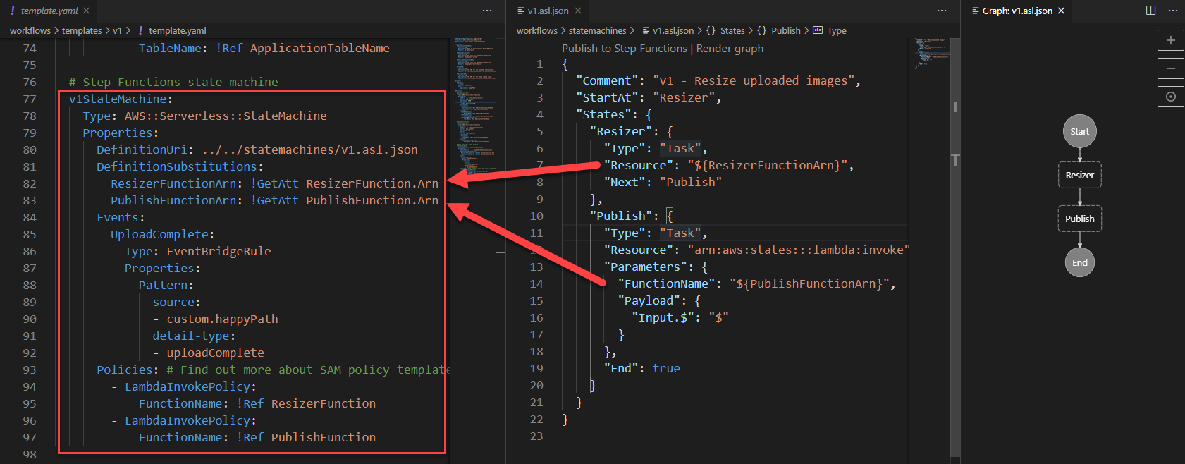
In part 1, I show how the application works and walk through the backend architecture. In part 2, you deploy a basic image-processing workflow. To do this, you use an AWS Serverless Application Model (AWS SAM) template to create an AWS Step Functions state machine.

In this post, I show how to deploy progressively more complex workflow functionality while using minimal code. This solution in this web app is designed for 100,000 monthly active users. Using this approach, you can introduce more sophisticated workflows without affecting the existing backend application.

The code and instructions for this application are available in the GitHub repo.

Introducing image moderation

In the first version, users could upload any images to parks on the map. One of the most important feature requests is to enable moderation, to prevent inappropriate images from appearing on the app. To handle a large number of uploaded images, using human moderation would be slow and labor-intensive.

In this section, you use Amazon ML services to automate analyzing the images for unsafe content. Amazon Rekognition provides an API to detect if an image contains moderation labels. These labels are categorized into different types of unsafe content that would not be appropriate for this app.

Version 2 of the workflow uses this API to automate the process of checking images. To install version 2:

  1. From a terminal window, delete the v1 workflow stack:
    aws cloudformation delete-stack --stack-name happy-path-workflow-v1
  2. Change directory to the version 2 AWS SAM template in the repo:
    cd .\workflows\templates\v2
  3. Build and deploy the solution:
    sam build
    sam deploy --guided
  4. The deploy process prompts you for several parameters. Enter happy-path-workflow-v2 as the Stack Name. The other values are the outputs from the backend deployment process, detailed in the repo’s README. Enter these to complete the deployment.

From VS Code, open the v2 state machine in the repo from workflows/statemachines/v2.asl.json. Choose the Render graph option in the CodeLens to see the workflow visualization.

Serverless workflow visualization

This new workflow introduces a Moderator step. This invokes a Moderator Lambda function that uses the Amazon Rekognition API. If this API identifies any unsafe content labels, it returns these as part of the function output.

The next step in the workflow is a Moderation result choice state. This evaluates the output of the previous function – if the image passes moderation, the process continues to the Resizer function. If it fails, execution moves to the RecordFailState step.

Step Functions integrates directly with some AWS services so that you can call and pass parameters into the APIs of those services. The RecordFailState uses an Amazon DynamoDB service integration to write the workflow failure to the application table, using the arn:aws:states:::dynamodb:updateItem resource.

Testing the workflow

To test moderation, I use an unsafe image with suggestive content. This is an image that is not considered appropriate for this application. To test the deployed v2 workflow:

  1. Open the frontend application at https://localhost:8080 in your browser.
  2. Select a park location, choose Show Details, and then choose Upload images.
  3. Select an unsafe image to upload.
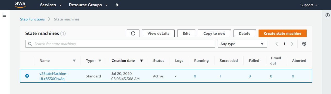
  4. Navigate to the Step Functions console. This shows the v2StateMachine with one successful execution:State machine result
  5. Select the state machine, and choose the execution to display more information. Scroll down to the Visual workflow panel.Visual workflow panel

This shows that the moderation failed and the path continued to log the failed state in the database. If you open the Output resource, this displays more details about why the image is considered unsafe.

Checking the image size and file type

The upload component in the frontend application limits file selection to JPG images but there is no check to reject images that are too small. It’s prudent to check and enforce image types and sizes on the backend API in addition to the frontend. This is because it’s possible to upload images via the API without using the frontend.

The next version of the workflow enforces image sizes and file types. To install version 3:

  1. From a terminal window, delete the v2 workflow stack:
    aws cloudformation delete-stack --stack-name happy-path-workflow-v2
  2. Change directory to the version 3 AWS SAM template in the repo:
    cd .\workflows\templates\v3
  3. Build and deploy the solution:
    sam build
    sam deploy --guided
  4. The deploy process prompts you for several parameters. Enter happy-path-workflow-v3 as the Stack Name. The other values are the outputs from the backend deployment process, detailed in the repo’s README. Enter these to complete the deployment.

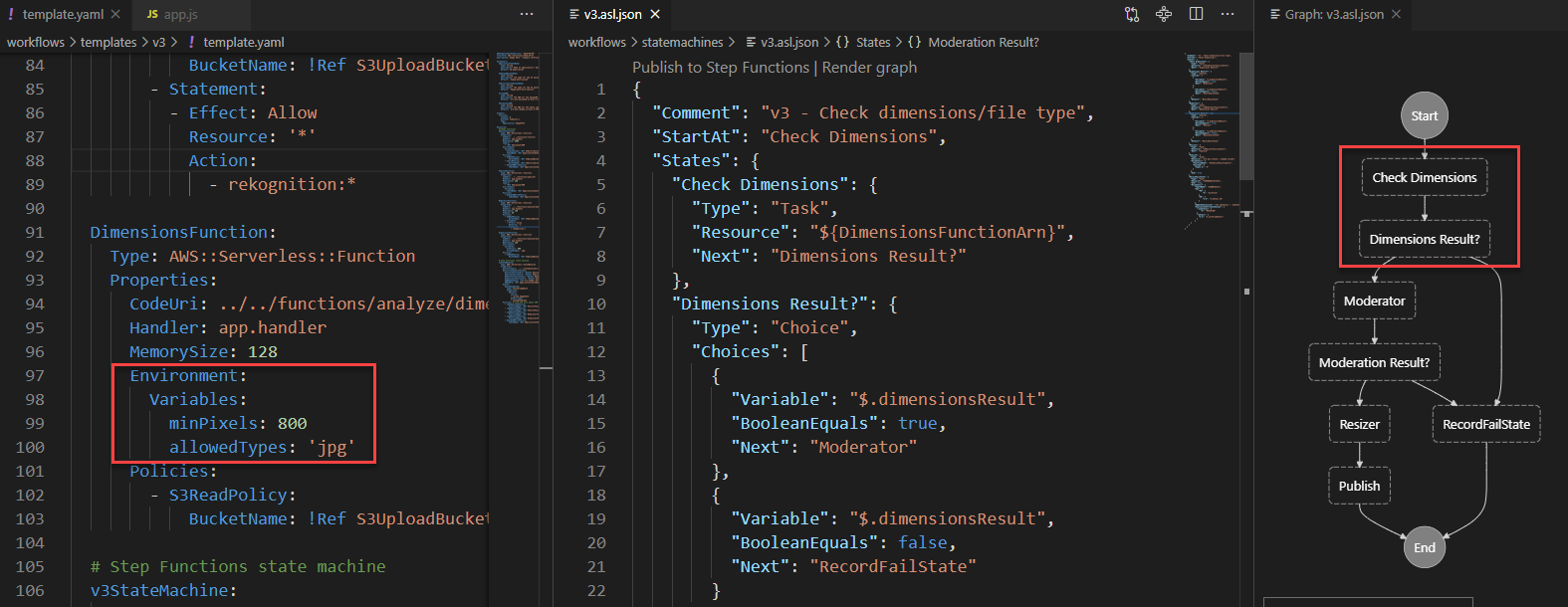
From VS Code, open the v3 state machine in the repo from workflows/statemachines/v3.asl.json. Choose the Render graph option in the CodeLens to see the workflow visualization.

v3 state machine

This workflow changes the starting point of the execution, introducing a Check Dimensions step. This invokes a Lambda function that checks the size and types of the Amazon S3 object using the image-size npm package. This function uses environment variables provided by the AWS SAM template to compare against a minimum size and allowed type array.

The output is evaluated by the Dimension Result choice state. If the image is larger than the minimum size allowed, execution continues to the Moderator function as before. If not, it passes to the RecordFailState step to log the result in the database.

Testing the workflow

To test, I use an image that’s narrower than the mixPixels value. To test the deployed v3 workflow:

  1. Open the frontend application at https://localhost:8080 in your browser.
  2. Select a park location, choose Show Details, and then choose Upload images.
  3. Select an image with a width smaller than 800 pixels. After a few seconds, a rejection message appears:"Image is too small" message
  4. Navigate to the Step Functions console. This shows the v3StateMachine with one successful execution. Choose the execution to show more detail.Execution output

The execution shows that the Check Dimension step added the image dimensions to the event object. Next, the Dimensions Result choice state rejected the image, and logged the result at the RecordFailState step. The application’s DynamoDB table now contains details about the failed upload:

DynamoDB item details

Pivoting the application to a new concept

Until this point, the Happy Path web application is designed to help park visitors share maps and photos. This is the development team’s original idea behind the app. During the product-market fit stage of development, it’s common for applications to pivot substantially from the original idea. For startups, it can be critical to have the agility to modify solutions quickly to meet the needs of customers.

In this scenario, the original idea has been less successful than predicted, and park visitors are not adopting the app as expected. However, the business development team has identified a new opportunity. Restaurants would like an app that allows customers to upload menus and food photos. How can the development team create a new proof-of-concept app for restaurant customers to test this idea?

In this version, you modify the application to work for restaurants. While features continue to be added to the parks workflow, it now supports business logic specifically for the restaurant app.

To create the v4 workflow and update the frontend:

  1. From a terminal window, delete the v3 workflow stack:
    aws cloudformation delete-stack --stack-name happy-path-workflow-v3
  2. Change directory to the version 4 AWS SAM template in the repo:
    cd .\workflows\templates\v4
  3. Build and deploy the solution:
    sam build
    sam deploy --guided
  4. The deploy process prompts you for several parameters. Enter happy-path-workflow-v4 as the Stack Name. The other values are the outputs from the backend deployment process, detailed in the repo’s README. Enter these to complete the deployment.
  5. Open frontend/src/main.js and update the businessType variable on line 63. Set this value to ‘restaurant’.Change config to restaurants
  6. Start the local development server:
    npm run serve
  7. Open the application at http://localhost:8080. This now shows restaurants in the local area instead of parks.

In the Step Functions console, select the v4StateMachine to see the latest workflow, then open the Definition tab to see the visualization:

Workflow definition

This workflow starts with steps that apply to both parks and restaurants – checking the image dimensions. Next, it determines the place type from the placeId record in DynamoDB. Depending on place type, it now follows a different execution path:

  • Parks continue to run the automated moderator process, then resizer and publish the result.
  • Restaurants now use Amazon Rekognition to determine the labels in the image. Any photos containing people are rejected. Next, the workflow continues to the resizer and publish process.
  • Other business types go to the RecordFailState step since they are not supported.

Testing the workflow

To test the deployed v4 workflow:

  1. Open the frontend application at https://localhost:8080 in your browser.
  2. Select a restaurant, choose Show Details, and then choose Upload images.
  3. Select an image from the test photos dataset. After a few seconds, you see a message confirming the photo has been added.
  4. Next, select an image that contains one or more people. The new restaurant workflow rejects this type of photo:"Image rejected" message
  5. In the Step Functions console, select the last execution for the v4StateMachine to see how the Check for people step rejected the image:v4 workflow

If other business types are added later to the application, you can extend the Step Functions workflow accordingly. The cost of Step Functions is based on the number of transitions in a workflow, not the number of total steps. This means you can branch by business type in the Happy Path application. This doesn’t affect the overall cost of running an execution, if the total transitions are the same per execution.

Conclusion

Previously in this series, you deploy a simple workflow for processing image uploads in the Happy Path web application. In this post, you add progressively more complex functionality by deploying new versions of workflows.

The first iteration introduces image moderation using Amazon Rekognition, providing the ability to automate the evaluation of unsafe content. Next, the workflow is modified to check image size and file type. This allows you to reject any images that are too small or do not meet the type requirements. Finally, I show how to expand the logic further to accept other business types with their own custom workflows.

To learn more about building serverless web applications, see the Ask Around Me series.

Configure and optimize performance of Amazon Athena federation with Amazon Redshift

Post Syndicated from Harsha Tadiparthi original https://aws.amazon.com/blogs/big-data/configure-and-optimize-performance-of-amazon-athena-federation-with-amazon-redshift/

This post provides guidance on how to configure Amazon Athena federation with AWS Lambda and Amazon Redshift, while addressing performance considerations to ensure proper use.

If you use data lakes in Amazon Simple Storage Service (Amazon S3) and use Amazon Redshift as your data warehouse, you may want to integrate the two for a lake house approach. Lake House is the ability to integrate Data Lake and Data warehouse seamlessly. When you need to query your data lake from your Amazon Redshift Data warehouse, you can use Amazon Redshift Spectrum, which works great in unifying your data lake and data warehouse. However, when you use Athena in the data lake and need to access data in Amazon Redshift for the following two scenarios which are commonly seen, there is no easy approach:

  • Team A has a data lake in Amazon S3 and uses Athena. They need access to the data in an Amazon Redshift cluster owned by Team B.
  • Analysts using Athena to query their data lake for analytics need agility and flexibility to access data in an Amazon Redshift data warehouse without moving the data to Amazon S3 Data Lake.

In these scenarios, Athena federation with Amazon Redshift allows you to seamlessly access the data in your Amazon Redshift data warehouse without having to wait to unload the data to the Amazon S3 data lake, which removes the overhead in managing such jobs.

In this post, you walk through a step-by-step configuration to set up Athena federation using Lambda to access data in Amazon Redshift. You also see a performance benchmark analysis of interactive and ad hoc TPC-DS queries, and learn some key performance considerations and best practices when using federation.

Solution overview

Data federation is the capability to integrate data in another data store using a single interface. The following diagram depicts how Athena federation works by using Lambda to integrate with a federated data source.

Athena is an interactive query service that makes it easy to analyze data in Amazon S3 using standard SQL. Athena is serverless, so there is no infrastructure to manage, and you pay only for the queries that you run. Simply point to your data in Amazon S3, define the schema, and start querying using standard SQL.

Lambda lets you run code without provisioning or managing servers. You can run code for virtually any type of application with zero administration and only pay for when the code is running.

Amazon Redshift is a petabyte-scale data warehouse designed from the ground up, natively for the cloud. Amazon Redshift is the most popular and fastest cloud data warehouse. It’s integrated with your data lake, offers performance up to three times faster than any other data warehouse, and costs up to 75% less than any other cloud data warehouse.

The following diagram depicts all the data source connectors available as of this writing in the AWS Serverless Application Repository.

The AWS Serverless Application Repository is a managed repository for serverless applications. It enables you to store and share reusable applications, and easily assemble and deploy serverless architectures in powerful new ways.

You can also create a custom connector for sources that aren’t in the AWS Serverless Application Repository.

Prerequisites

Before you get started, create a secret for the Amazon Redshift login ID and password using AWS Secrets Manager.

  1. On the Secrets Manager console, choose Secrets.
  2. Choose Store a new secret.
  3. Choose credentials for your Amazon Redshift cluster, and set your user name and password.
  4. Choose the cluster you want to use.
  5. For Secret name, enter a name for your secret. Use the prefix AthenaJDBCFederation so it’s easy to find.
  6. Leave the remaining fields at their defaults and choose Next.
  7. Complete your secret creation.

Setting up your S3 bucket

On the Amazon S3 console, create a new S3 bucket and subfolder for Lambda to use. For this post, use the name myworkspace0009/athenafederation.

Configuring Athena federation with Amazon Redshift

To configure Athena federation with Amazon Redshift, complete the following steps:

  1. On the AWS Serverless Application Repository, choose Available applications.
  2. In the search field, enter athena federation.

  1. Choose
  2. In the Application settings section, provide the following details:
  3. Application name – AthenaRedshiftConnector
  4. SecretNamePrefix – AthenaJdbcFederation
  5. SpillBucket – myworkspace0009/athenafederation
  6. JDBCConnectorConfig – Redshift://jdbc:Redshift://<YourAmazon Redshift1Hostname>:5439/<DBName>?user=sample2&password=sample2
  7. DisableSpillEncyption – False
  8. LambdaFunctionName – rstpcds30
  9. SecurityGroupID – Security group ID where Amazon Redshift is deployed
  10. SpillPrefix – Leave default
  11. Subnetids – Use the subnets where Amazon Redshift is running with comma separation
  12. Select the I acknowledge check box.
  13. Choose Deploy.

In the next steps, you configure an Amazon Virtual Private Cloud (Amazon VPC) endpoint for Amazon S3 to allow Lambda to write federated query results to Amazon S3.

  1. On the Amazon VPC console, choose Endpoints.
  2. Choose Create endpoint.
  3. Choose the VPC for your endpoint.

  1. Make any necessary security changes as per your security requirements.

  1. Choose Create endpoint.

Running federated queries with Athena

To start running federated queries, complete the following steps:

  1. On the Athena console, choose Workgroups.
  2. If you don’t see a workgroup called AmazonAthenaPreviewFunctionality, create one.

When this feature becomes generally available, you won’t need to use this workgroup name.

  1. Run your queries, using lambda:rstpcds30 to run against tables in Amazon Redshift.

Athena query performance comparison

Several customers have asked us for performance insights and prescriptive guidance on how queries in Athena compare against federated queries and how to use them. In this section, we use a TPC-DS 3 TB standard dataset and a select few queries that fall in the category of ad hoc and interactive. The comparison of their performance should give you an idea of what to expect when running federated queries against Amazon Redshift.

For the following tests, we used a 3 TB TPC-DS dataset in Amazon S3 data lake with Parquet compressed, partitioned and served by Athena, and the same 3 TB TPC-DS dataset on Amazon Redshift cluster running four RA3.4XL nodes.

The following table summarizes the dataset sizes:

Dataset Table Size (Records)
store_sales 8.6 billion
customer 30 million
customer_address 15 million
customer_demographics 1.92 million
item 360,000
date_dim 73,000
store 1,350

We ran the following four tests:

  • T1 – Queries ran in Athena without federation. All table data is in Amazon S3.
  • T2 – Queries ran in Athena with federation to Amazon Redshift. All table data is in Amazon S3, except the store_sales fact table in Amazon Redshift.
  • T3 – Queries ran in Athena with federation to Amazon Redshift. All tables and data are in Redshift.
  • T4 – Queries ran in Amazon Redshift without federation. All tables and data are in Redshift.

The following graph represents the performance of some of the ad hoc and interactive TPC-DS queries.

In the preceding graph, all T3 queries timed out at 900 seconds, depicted by the pink reference line, due to the Lambda 900-second timeout limit. This is due to overhead from store_sales fact data that needed to be transferred back to Athena.

The following graph removes T3 from the visualization, which gives better visibility when comparing the other tests.

Notice the query performance between T1 and T2 that completed in almost the same time while T4 queries ran significantly faster.

Amazon Redshift beats the performance of Athena in providing extremely low latency and should be the tool of choice if you’re looking for very low SLAs for analytics queries that Athena can’t achieve.

The following graph shows the data scanned in Amazon S3 for T1 and T2, which outlines why there isn’t much difference in query performance when compared to federated queries.

For the T2 federated queries, a small amount of dimension data is filtered in Amazon Redshift and brought back to Athena, instead of scanning the entire dimension tables. This is a typical nature for several ad hoc and interactive queries.

The performance of these TPC-DS queries between T1 and T2 is comparable because very little data is transferred back to Athena. You can see a similar behavior in several ad hoc and interactive query use cases because they use limited dimensions and scan a small subset of dimension data. Due to the 900-second timeout for the Lambda instances that connect to Amazon Redshift, it’s advised to minimize the amount of data the query brings back. Although Athena uses multiple Lambda instances in parallel to run your federated query, it’s also important to make sure the Amazon Redshift WLM queue has enough slots to process it, thereby not leading to queue wait time. For example, in some of the preceding queries, 20 Lambda executions were connecting to Amazon Redshift concurrently.

Key performance best practice considerations

When considering Athena federation with Amazon Redshift, you could take into account the following best practices:

  • Athena federation works great for queries with predicate filtering because the predicates are pushed down to Amazon Redshift. Use filter and limited-range scans in your queries to avoid full table scans.
  • If your SQL query requires returning a large volume of data from Amazon Redshift to Athena (which could lead to query timeouts or slow performance), unload the large tables in your query from Redshift to your Amazon S3 data lake.
  • Star schema is a commonly used data model in Amazon Redshift. In the star schema model, unload your large fact tables into your data lake and leave the dimension tables in Amazon Redshift. If large dimension tables are contributing to slow performance or query timeouts, unload those tables to your data lake.
  • When you run federated queries, Athena spins up multiple Lambda functions, which causes a spike in database connections. It’s important to monitor the Amazon Redshift WLM queue slots to ensure there is no queuing. Additionally, you can use concurrency scaling on your Amazon Redshift cluster to benefit from concurrent connections to queue up.

Conclusion

In this post, you learned how to configure and use Athena federation with Amazon Redshift using Lambda. Now you don’t need to wait for all the data in your Amazon Redshift data warehouse to be unloaded to Amazon S3 and maintained on a day-to-day basis to run your queries. You can use the best practice considerations outlined in the post to minimize the data transferred from Amazon Redshift for better performance. When queries are well written for federation, the performance penalties are negligible, as observed in the TPC-DS benchmark queries in this post. Happy query federating!


About the Author

Harsha Tadiparthi is a Specialist Sr. Solutions Architect, AWS Analytics. He enjoys solving complex customer problems in Databases and Analytics and delivering successful outcomes. Outside of work, he loves to spend time with his family, watch movies, and travel whenever possible.



Building Salesforce integrations with Amazon EventBridge and Amazon AppFlow

Post Syndicated from James Beswick original https://aws.amazon.com/blogs/compute/building-salesforce-integrations-with-amazon-eventbridge/

This post is courtesy of Den Delimarsky, Senior Product Manager, and Vinay Kondapi, Senior Product Manager.

The integration between Amazon EventBridge and Amazon AppFlow enables customers to receive and react to events from Salesforce in their event-driven applications. In this blog post, I show you how to set up the integration, and route Salesforce events to an AWS Lambda function for processing.

Amazon AppFlow is a fully managed integration service that enables you to securely transfer data between software as a service (SaaS) applications like Salesforce, Marketo, Slack, and ServiceNow, and AWS services like Amazon S3 and Amazon Redshift.

EventBridge SaaS integrations make it easier for customers to receive events from over 30 different SaaS providers. Salesforce is a popular SaaS provider among AWS customers, so it has been one of the most anticipated event sources for EventBridge. Customers want to build rich applications that can react to events that track campaigns, contracts, opportunities, and order changes.

The ability to receive these events allows you to build workflows where you can start a variety of processes. For example, you could notify a broad range of subscribers about the changes, or enrich the data with information from another service. Or you could route the event to an order delivery system.

Previously, to connect Salesforce to your application, you must write custom API polling code that routes events either directly to an application or to an event bus. With the Salesforce integration with EventBridge and Amazon AppFlow, the integration is built in minutes directly through the AWS Management Console, with no code required.

The solution outlined in this blog post is structured as follows:

Architecture overview

Setting up the event source

To set up the event source:

  1. Open the Amazon AppFlow console, and create a new flow. Choose Create flow button on the service landing page. Give your flow a unique name, and choose Next.Specify flow details
  2. In the Source name list, select Salesforce, and then choose Connect. Select the Salesforce environment you are using, and provide a unique connection name.Connect to Salesforce
  3. Choose Continue. When prompted, provide your Salesforce credentials. These are the credentials that are associated with the specific Salesforce environment selected in the previous step.
  4. Select Salesforce events from the list of available options for the flow, and choose the event that you want to route to EventBridge. This ensures that Amazon AppFlow can route specific events that are coming from Salesforce to an EventBridge event bus.Source details
  5. With the source set up, you can now specify the destination. In the Destination name list, select EventBridge.Destination name

To send Salesforce events to EventBridge, Amazon AppFlow creates a new partner event source that is associated with a partner event bus.

To create a partner event source:

  1. Select an existing partner event source, or create a new one by choosing the list of partner event sources.Destination details
  2. When creating a new event source, you can optionally customize the name, to make it easier for you to identify it later.Generate partner event source
  3. Choose an Amazon S3 bucket for large events. For events that are larger than 256 KB, Amazon AppFlow sends a URL for the S3 object to the event bus instead of the event payload.Large event handling
  4. Define a flow trigger, which determines when the flow is started. Because we are tracking events, we want to react to those as they come in. Using the default Run flow on event enables this scenario as changes occur in Salesforce.Flow trigger

With Amazon AppFlow, you can also configure data field mapping, validation rules, and filters. These enable you to enrich and modify event data before it is sent to the event bus.

Once you create the flow, you must activate the event source that you created. To complete this step:

  1. Open the EventBridge console.
  2. Associate a partner event source with an event bus by following the link in the Amazon AppFlow integration dialog box, or navigating directly to the partner event sources view. You can see a partner event source with a Pending state.Partner event source
  3. Select the event source and choose Associate with event bus.
  4. Confirm the settings and choose on Associate.Associate with an event bus
  5. Return to the Amazon AppFlow console, and open the flow you were creating. Choose Activate flow.Activate flow

Your integration is now complete, and EventBridge can start receiving Salesforce events from the configured flow.

Routing Salesforce events to Lambda function

The associated partner event bus receives all events of the configured type from the connected Salesforce accounts. Now your application can react to these events with the help of rules in EventBridge. Rules allow you to set conditions for event routing that determine what targets receive event payloads. You can learn more about this functionality in the EventBridge documentation.

To create a new rule:

  1. Go to the rules view in the EventBridge console, and choose Create rule.EventBridge Rules
  2. Provide a unique name and an optional description for your rule.
  3. Select the Event pattern option in the Define pattern section. With event pattern configuration, you can define parts of the event payload that EventBridge must look at to determine where to route the event.Define pattern
    For this exercise, start by capturing every Salesforce event that goes through the partner event bus. The only events routed through this bus are from the partner event source. In this case, it is Amazon AppFlow connected to Salesforce.
  4. Set the event matching pattern to Pre-defined pattern by service, with the service provider being All Events. The default setting allows you to receive all events that are coming through the partner event bus.Event matching pattern
  5. Select the event bus that the rule should be associated with. Choose Custom or partner event bus and select the event bus that you associated with the Amazon AppFlow event source. Every rule in EventBridge is associated with an event bus.Select event bus

When rules are triggered, the event can be routed to other AWS services. Additionally, every rule can have up to five different AWS targets. You can read more about available targets in the EventBridge documentation. For this blog post, we use an AWS Lambda function as a target for Salesforce events received from Amazon AppFlow.

To configure targets for your rule:

  1. From the list of targets, select Lambda function, and select an existing function. If you do not yet have a function available, you can create one in the AWS Lambda console.Select targets
  2. Choose Create. You have now completed the rule setup.

Now, Salesforce events that match the configured type are routed directly to a Lambda function in your account.

Testing the integration

To test the integration:

  1. Open the Lambda view in the AWS Management Console.
  2. Choose the function that is handling the events from EventBridge.
  3. In the Function code section, update the code to:
    exports.handler = async (event) => {
        console.log(event);
        const response = {
            statusCode: 200,
            body: JSON.stringify('Hello from Lambda!'),
        };
        return response;
    };
    

    Function code

  4. Choose Save.
  5. Open your Salesforce instance, and take an action that is associated with the event you configured earlier. For example, you could update a contract or create an order.
  6. Go back to your function in AWS Management Console, and choose the Monitoring tab.Lambda function monitoring tab
  7. Scroll to CloudWatch Logs Insights section.CloudWatch Logs Insights
  8. Choose the latest log stream. Make sure that the timestamp approximately matches the time when you triggered the action in Salesforce.
  9. Choose the log stream.
  10. Observe log events that contain Salesforce event data.

You have completed your first Salesforce integration with EventBridge and Amazon AppFlow. You are now able to build decoupled and highly scalable applications that integrate with Salesforce.

Conclusion

Building decoupled and scalable cross-service applications is more relevant than ever with requirements for high availability, consistency, and reliability. This blog post demonstrates a solution that connects Salesforce to an event-driven application that uses EventBridge and Amazon AppFlow to route events. The application uses events from Salesforce as a starting point for a custom processing workflow in a Lambda function.

To learn more about EventBridge, visit the EventBridge documentation or EventBridge Learning Path.

To learn more about Amazon AppFlow, visit the Amazon AppFlow documentation.

Building storage-first serverless applications with HTTP APIs service integrations

Post Syndicated from Eric Johnson original https://aws.amazon.com/blogs/compute/building-storage-first-applications-with-http-apis-service-integrations/

Over the last year, I have been talking about “storage first” serverless patterns. With these patterns, data is stored persistently before any business logic is applied. The advantage of this pattern is increased application resiliency. By persisting the data before processing, the original data is still available, if or when errors occur.

Common pattern for serverless API backend

Common pattern for serverless API backend

Using Amazon API Gateway as a proxy to an AWS Lambda function is a common pattern in serverless applications. The Lambda function handles the business logic and communicates with other AWS or third-party services to route, modify, or store the processed data. One option is to place the data in an Amazon Simple Queue Service (SQS) queue for processing downstream. In this pattern, the developer is responsible for handling errors and retry logic within the Lambda function code.

The storage first pattern flips this around. It uses native error handling with retry logic or dead-letter queues (DLQ) at the SQS layer before any code is run. By directly integrating API Gateway to SQS, developers can increase application reliability while reducing lines of code.

Storage first pattern for serverless API backend

Storage first pattern for serverless API backend

Previously, direct integrations require REST APIs with transformation templates written in Velocity Template Language (VTL). However, developers tell us they would like to integrate directly with services in a simpler way without using VTL. As a result, HTTP APIs now offers the ability to directly integrate with five AWS services without needing a transformation template or code layer.

The first five service integrations

This release of HTTP APIs direct integrations includes Amazon EventBridge, Amazon Kinesis Data Streams, Simple Queue Service (SQS), AWS System Manager’s AppConfig, and AWS Step Functions. With these new integrations, customers can create APIs and webhooks for their business logic hosted in these AWS services. They can also take advantage of HTTP APIs features like authorizers, throttling, and enhanced observability for securing and monitoring these applications.

Amazon EventBridge

HTTP APIs service integration with Amazon EventBridge

HTTP APIs service integration with Amazon EventBridge

The HTTP APIs direct integration for EventBridge uses the PutEvents API to enable client applications to place events on an EventBridge bus. Once the events are on the bus, EventBridge routes the event to specific targets based upon EventBridge filtering rules.

This integration is a storage first pattern because data is written to the bus before any routing or logic is applied. If the downstream target service has issues, then EventBridge implements a retry strategy with incremental back-off for up to 24 hours. Additionally, the integration helps developers reduce code by filtering events at the bus. It routes to downstream targets without the need for a Lambda function as a transport layer.

Use this direct integration when:

  • Different tasks are required based upon incoming event details
  • Only data ingestion is required
  • Payload size is less than 256 kb
  • Expected requests per second are less than the Region quotas.

Amazon Kinesis Data Streams

HTTP APIs service integration with Amazon Kinesis Data Streams

HTTP APIs service integration with Amazon Kinesis Data Streams

The HTTP APIs direct integration for Kinesis Data Streams offers the PutRecord integration action, enabling client applications to place events on a Kinesis data stream. Kinesis Data Streams are designed to handle up to 1,000 writes per second per shard, with payloads up to 1 mb in size. Developers can increase throughput by increasing the number of shards in the data stream. You can route the incoming data to targets like an Amazon S3 bucket as part of a data lake or a Kinesis data analytics application for real-time analytics.

This integration is a storage first option because data is stored on the stream for up to seven days until it is processed and routed elsewhere. When processing stream events with a Lambda function, errors are handled at the Lambda layer through a configurable error handling strategy.

Use this direct integration when:

  • Ingesting large amounts of data
  • Ingesting large payload sizes
  • Order is important
  • Routing the same data to multiple targets

Amazon SQS

HTTP APIs service integration with Amazon SQS

HTTP APIs service integration with Amazon SQS

The HTTP APIs direct integration for Amazon SQS offers the SendMessage, ReceiveMessage, DeleteMessage, and PurgeQueue integration actions. This integration differs from the EventBridge and Kinesis integrations in that data flows both ways. Events can be created, read, and deleted from the SQS queue via REST calls through the HTTP API endpoint. Additionally, a full purge of the queue can be managed using the PurgeQueue action.

This pattern is a storage first pattern because the data remains on the queue for four days by default (configurable to 14 days), unless it is processed and removed. When the Lambda service polls the queue, the messages that are returned are hidden in the queue for a set amount of time. Once the calling service has processed these messages, it uses the DeleteMessage API to remove the messages permanently.

When triggering a Lambda function with an SQS queue, the Lambda service manages this process internally. However, HTTP APIs direct integration with SQS enables developers to move this process to client applications without the need for a Lambda function as a transport layer.

Use this direct integration when:

  • Data must be received as well as sent to the service
  • Downstream services need reduced concurrency
  • The queue requires custom management
  • Order is important (FIFO queues)

AWS AppConfig

HTTP APIs service integration with AWS Systems Manager AppConfig

HTTP APIs service integration with AWS Systems Manager AppConfig

The HTTP APIs direct integration for AWS AppConfig offers the GetConfiguration integration action and allows applications to check for application configuration updates. By exposing the systems parameter API through an HTTP APIs endpoint, developers can automate configuration changes for their applications. While this integration is not considered a storage first integration, it does enable direct communication from external services to AppConfig without the need for a Lambda function as a transport layer.

Use this direct integration when:

  • Access to AWS AppConfig is required.
  • Managing application configurations.

AWS Step Functions

HTTP APIs service integration with AWS Step Functions

HTTP APIs service integration with AWS Step Functions

The HTTP APIs direct integration for Step Functions offers the StartExecution and StopExecution integration actions. These actions allow for programmatic control of a Step Functions state machine via an API. When starting a Step Functions workflow, JSON data is passed in the request and mapped to the state machine. Error messages are also mapped to the state machine when stopping the execution.

This pattern provides a storage first integration because Step Functions maintains a persistent state during the life of the orchestrated workflow. Step Functions also supports service integrations that allow the workflows to send and receive data without needing a Lambda function as a transport layer.

Use this direct integration when:

  • Orchestrating multiple actions.
  • Order of action is required.

Building HTTP APIs direct integrations

HTTP APIs service integrations can be built using the AWS CLI, AWS SAM, or through the API Gateway console. The console walks through contextual choices to help you understand what is required for each integration. Each of the integrations also includes an Advanced section to provide additional information for the integration.

Creating an HTTP APIs service integration

Creating an HTTP APIs service integration

Once you build an integration, you can export it as an OpenAPI template that can be used with infrastructure as code (IaC) tools like AWS SAM. The exported template can also include the API Gateway extensions that define the specific integration information.

Exporting the HTTP APIs configuration to OpenAPI

Exporting the HTTP APIs configuration to OpenAPI

OpenAPI template

An example of a direct integration from HTTP APIs to SQS is located in the Sessions With SAM repository. This example includes the following architecture:

AWS SAM template resource architecture

AWS SAM template resource architecture

The AWS SAM template creates the HTTP APIs, SQS queue, Lambda function, and both Identity and Access Management (IAM) roles required. This is all generated in 58 lines of code and looks like this:

AWSTemplateFormatVersion: '2010-09-09'
Transform: AWS::Serverless-2016-10-31
Description: HTTP API direct integrations

Resources:
  MyQueue:
    Type: AWS::SQS::Queue
    
  MyHttpApi:
    Type: AWS::Serverless::HttpApi
    Properties:
      DefinitionBody:
        'Fn::Transform':
          Name: 'AWS::Include'
          Parameters:
            Location: './api.yaml'
          
  MyHttpApiRole:
    Type: "AWS::IAM::Role"
    Properties:
      AssumeRolePolicyDocument:
        Version: "2012-10-17"
        Statement:
          - Effect: "Allow"
            Principal:
              Service: "apigateway.amazonaws.com"
            Action: 
              - "sts:AssumeRole"
      Policies:
        - PolicyName: ApiDirectWriteToSQS
          PolicyDocument:
            Version: '2012-10-17'
            Statement:
              Action:
              - sqs:SendMessage
              Effect: Allow
              Resource:
                - !GetAtt MyQueue.Arn
                
  MyTriggeredLambda:
    Type: AWS::Serverless::Function
    Properties:
      CodeUri: src/
      Handler: app.lambdaHandler
      Runtime: nodejs12.x
      Policies:
        - SQSPollerPolicy:
            QueueName: !GetAtt MyQueue.QueueName
      Events:
        SQSTrigger:
          Type: SQS
          Properties:
            Queue: !GetAtt MyQueue.Arn

Outputs:
  ApiEndpoint:
    Description: "HTTP API endpoint URL"
    Value: !Sub "https://${MyHttpApi}.execute-api.${AWS::Region}.amazonaws.com"

The OpenAPI template handles the route definitions for the HTTP API configuration and configures the service integration. The template looks like this:

openapi: "3.0.1"
info:
  title: "my-sqs-api"
paths:
  /:
    post:
      responses:
        default:
          description: "Default response for POST /"
      x-amazon-apigateway-integration:
        integrationSubtype: "SQS-SendMessage"
        credentials:
          Fn::GetAtt: [MyHttpApiRole, Arn]
        requestParameters:
          MessageBody: "$request.body.MessageBody"
          QueueUrl:
            Ref: MyQueue
        payloadFormatVersion: "1.0"
        type: "aws_proxy”
        connectionType: "INTERNET"
x-amazon-apigateway-importexport-version: "1.0"

Because the OpenAPI template is included in the AWS SAM template via a transform, the API Gateway integration can reference the roles and services created within the AWS SAM template.

Conclusion

This post covers the concept of storage first integration patterns and how the new HTTP APIs direct integrations can help. I cover the five current integrations and possible use cases for each. Additionally, I demonstrate how to use AWS SAM to build and manage the integrated applications using infrastructure as code.

Using the storage first pattern with direct integrations can help developers build serverless applications that are more durable with fewer lines of code. A Lambda function is no longer required to transport data from the API endpoint to the desired service. Instead, use Lambda function invocations for differentiating business logic.

To learn more join us for the HTTP API service integrations session of Sessions With SAM! 

#ServerlessForEveryone

Fundbox: Simplifying Ways to Query and Analyze Data by Different Personas

Post Syndicated from Annik Stahl original https://aws.amazon.com/blogs/architecture/fundbox-simplifying-ways-to-query-and-analyze-data-by-different-personas/

Fundbox is a leading technology platform focused on disrupting the $21 trillion B2B commerce market by building the world’s first B2B payment and credit network. With Fundbox, sellers of all sizes can quickly increase average order volumes (AOV) and improve close rates by offering more competitive net terms and payment plans to their SMB buyers. With heavy investments in machine learning and the ability to quickly analyze the transactional data of SMB’s, Fundbox is reimagining B2B payments and credit products in new category-defining ways.

Learn how how the company simplified the way different personas in the organization query and analyze data by building a self-service data orchestration platform. The platform architecture is entirely serverless, which simplifies the ability to scale and adopt to unpredictable demand. The platform was built using AWS Step Functions, AWS Lambda, Amazon API Gateway, Amazon DynamoDB, AWS Fargate, and other AWS Serverless managed services.

For more content like this, subscribe to our YouTube channels This is My Architecture, This is My Code, and This is My Model, or visit the This is My Architecture on AWS, which has search functionality and the ability to filter by industry, language, and service.

Using serverless backends to iterate quickly on web apps – part 2

Post Syndicated from James Beswick original https://aws.amazon.com/blogs/compute/using-serverless-backends-to-iterate-quickly-on-web-apps-part-2/

This series is about building flexible solutions that can adapt as user requirements change. One of the challenges of building modern web applications is that requirements can change quickly. This is especially true for new applications that are finding their product-market fit. Many development teams start building a product with one set of requirements, and quickly find they must build a product with different features.

For both start-ups and enterprises, it’s often important to find a development methodology and architecture that allows flexibility. This is the surest way to keep up with feature requests in evolving products and innovate to delight your end-users. In this post, I show how to build sophisticated workflows using minimal custom code.

Part 1 introduces the Happy Path application that allows park visitors to share maps and photos with other users. In that post, I explain the functionality, how to deploy the application, and walk through the backend architecture.

The Happy Path application accepts photo uploads from users’ smartphones. The application architecture must support 100,000 monthly active users. These binary uploads are typically 3–9 MB in size and must be resized and optimized for efficient distribution.

Using a serverless approach, you can develop a robust low-code solution that can scale to handle millions of images. Additionally, the solution shown here is designed to handle complex changes that are introduced in subsequent versions of the software. The code and instructions for this application are available in the GitHub repo.

Architecture overview

After installing the backend in the previous post, the architecture looks like this:

In this design, the API, storage, and notification layers exist as one application, and the business logic layer is a separate application. These two applications are deployed using AWS Serverless Application Model (AWS SAM) templates. This architecture uses Amazon EventBridge to pass events between the two applications.

In the business logic layer:

  1. The workflow starts when events are received from EventBridge. Each time a new object is uploaded by an end-user, the PUT event in the Amazon S3 Upload bucket triggers this process.
  2. After the workflow is completed successfully, processed images are stored in the Distribution bucket. Related metadata for the object is also stored in the application’s Amazon DynamoDB table.

By separating the architecture into two independent applications, you can replace the business logic layer as needed. Providing that the workflow accepts incoming events and then stores processed images in the S3 bucket and DynamoDB table, the workflow logic becomes interchangeable. Using the pattern, this workflow can be upgraded to handle new functionality.

Introducing AWS Step Functions for workflow management

One of the challenges in building distributed applications is coordinating components. These systems are composed of separate services, which makes orchestrating workflows more difficult than working with a single monolithic application. As business logic grows more complex, if you attempt to manage this in custom code, it can become quickly convoluted. This is especially true if it handles retries and error handling logic, and it can be hard to test and maintain.

AWS Step Functions is designed to coordinate and manage these workflows in distributed serverless applications. To do this, you create state machine diagrams using Amazon States Language (ASL). Step Functions renders a visualization of your state machine, which makes it simpler to see the flow of data from one service to another.

Each state machine consists of a series of steps. Each step takes an input and produces an output. Using ASL, you define how this data progresses through the state machine. The flow from step to step is called a transition. All state machines transition from a Start state towards an End state.

The Step Functions service manages the state of individual executions. The service also supports versioning, which makes it easier to modify state machines in production systems. Executions continue to use the version of a state machine when they were started, so it’s possible to have active executions on multiple versions.

For developers using VS Code, the AWS Toolkit extension provides support for writing state machines using ASL. It also renders visualizations of those workflows. Combined with AWS Serverless Application Model (AWS SAM) templates, this provides a powerful way to deploy and maintain applications based on Step Functions. I refer to this IDE and AWS SAM in this walkthrough.

Version 1: Image resizing

The Happy Path application uses Step Functions to manage the image-processing part of the backend. The first version of this workflow resizes the uploaded image.

To see this workflow:

  1. In VS Code, open the workflows/statemachines folder in the Explorer panel.
  2. Choose the v1.asl.sjon file.v1 state machine
  3. Choose the Render graph option in the CodeLens. This opens the workflow visualization.CodeLens - Render graph

In this basic workflow, the state machine starts at the Resizer step, then progresses to the Publish step before ending:

  • In the top-level attributes in the definition, StartsAt sets the Resizer step as the first action.
  • The Resizer step is defined as a task with an ARN of a Lambda function. The Next attribute determines that the Publish step is next.
  • In the Publish step, this task defines a Lambda function using an ARN reference. It sets the input payload as the entire JSON payload. This step is set as the End of the workflow.

Deploying the Step Functions workflow

To deploy the state machine:

  1. In the terminal window, change directory to the workflows/templates/v1 folder in the repo.
  2. Execute these commands to build and deploy the AWS SAM template:
    sam build
    sam deploy –guided
  3. The deploy process prompts you for several parameters. Enter happy-path-workflow-v1 as the Stack Name. The other values are the outputs from the backend deployment process, detailed in the repo’s README. Enter these to complete the deployment.
  4. SAM deployment output

Testing and inspecting the deployed workflow

Now the workflow is deployed, you perform an integration test directly from the frontend application.

To test the deployed v1 workflow:

  1. Open the frontend application at https://localhost:8080 in your browser.
  2. Select a park location, choose Show Details, and then choose Upload images.
  3. Select an image from the sample photo dataset.
  4. After a few seconds, you see a pop-up message confirming that the image has been added:Upload confirmation message
  5. Select the same park location again, and the information window now shows the uploaded image:Happy Path - park with image data

To see how the workflow processed this image:

  1. Navigate to the Steps Functions console.
  2. Here you see the v1StateMachine with one execution in the Succeeded column.Successful execution view
  3. Choose the state machine to display more information about the start and end time.State machine detail
  4. Select the execution ID in the Executions panel to open details of this single instance of the workflow.

This view shows important information that’s useful for understanding and debugging an execution. Under Input, you see the event passed into Step Functions by EventBridge:

Event detail from EventBridge

This contains detail about the S3 object event, such as the bucket name and key, together with the placeId, which identifies the location on the map. Under Output, you see the final result from the state machine, shows a successful StatusCode (200) and other metadata:

Event output from the state machine

Using AWS SAM to define and deploy Step Functions state machines

The AWS SAM template defines both the state machine, the trigger for executions, and the permissions needed for Step Functions to execute. The AWS SAM resource for a Step Functions definition is AWS::Serverless::StateMachine.

Definition permissions in state machines

In this example:

  • DefinitionUri refers to an external ASL definition, instead of embedding the JSON in the AWS SAM template directly.
  • DefinitionSubstitutions allow you to use tokens in the ASL definition that refer to resources created in the AWS SAM template. For example, the token ${ResizerFunctionArn} refers to the ARN of the resizer Lambda function.
  • Events define how the state machine is invoked. Here it defines an EventBridge rule. If an event matches this source and detail-type, it triggers an execution.
  • Policies: the Step Functions service must have permission to invoke the services that perform tasks in the state machine. AWS SAM policy templates provide a convenient shorthand for common execution policies, such as invoking a Lambda function.

This workflow application is separate from the main backend template. As more functionality is added to the workflow, you deploy the subsequent AWS SAM templates in the same way.

Conclusion

Using AWS SAM, you can specify serverless resources, configure permissions, and define substitutions for the ASL template. You can deploy a standalone Step Functions-based application using the AWS SAM CLI, separately from other parts of your application. This makes it easier to decouple and maintain larger applications. You can visualize these workflows directly in the VS Code IDE in addition to the AWS Management Console.

In part 3, I show how to build progressively more complex workflows and how to deploy these in-place without affecting the other parts of the application.

To learn more about building serverless web applications, see the Ask Around Me series.