Post Syndicated from Marco Fischer original https://aws.amazon.com/blogs/devops/aws-control-tower-account-vending-through-amazon-lex-chatbot/
In this blog post you will learn about a multi-environment solution that uses a cloud native CICD pipeline to build, test, and deploy a Serverless ChatOps bot that integrates with AWS Control Tower Account Factory for AWS account vending. This solution can be used and integrated with any of your favourite request portal or channel that allows to call a RESTFUL API endpoint, for you to offer AWS Account vending at scale for your enterprise.
Introduction
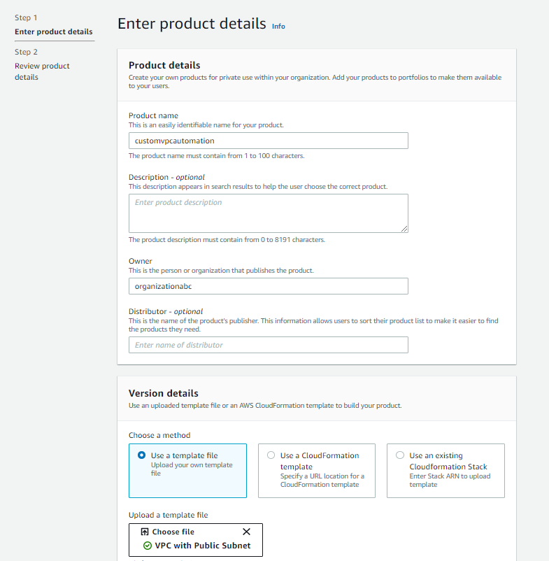
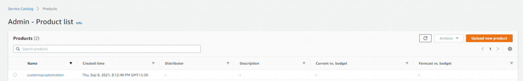
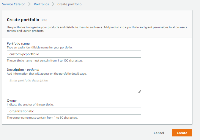
Most of the AWS Control Tower customers use the AWS Control Tower Account Factory (a Service Catalog product), and the ServiceCatalog service to vend standardized AWS Services and Products into AWS Accounts. ChatOps is a collaboration model that interconnects a process with people, tools, and automation. It combines a Bot that can fulfill service requests (the work needed) and be augmented by Ops and Engineering staff in order to allow approval processes or corrections in the case of exception request. Major tasks in the public Cloud go toward building a proper foundation (the so called LandingZone). The main goals of this foundation are providing not only an AWS Account access (with the right permissions), but also the correct Cloud Center of Excellence (CCoE) approved products and services. This post demonstrates how to utilize the existing AWS Control Tower Account Factory, extending the Service Catalog portfolio in Control Tower with additional products, and executing Account vending and Product vending through an easy ChatBot interface. You will also learn how to utilize this Solution with Slack. But it can also be easily utilized with Chime/MS Teams or a normal Web-frontend, as the integration is channel-agnostig through an API Gateway integration layer. Then, you will combine all of this, integrating a ChatBot frontend where users can issue requests against the CCoE and Ops team to fulfill AWS services easily and transparently. As a result, you experience a more efficient process for vending AWS Accounts and Products and taking away the burden on your Cloud Operations team.
Background
- An AWS Account Factory Account account is an AWS account provisioned using account factory in AWS Control Tower.
- AWS Service Catalog lets you to centrally manage commonly deployed IT services. For this blog, account factory utilizes AWS Service Catalog to provision new AWS accounts.
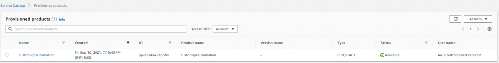
- A Control Tower provisioned product is an instance of the Control Tower Account Factory product that is provisioned by AWS Service Catalog. In this post, any new AWS account created through the ChatOps solution will be a provisioned product and visible in Service Catalog.
- Amazon Lex: is a service for building conversational interfaces into any application using voice and text
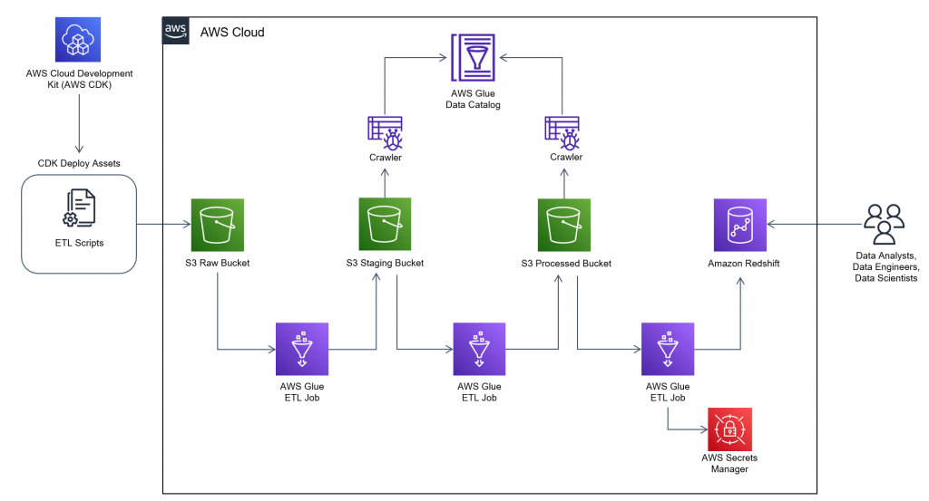
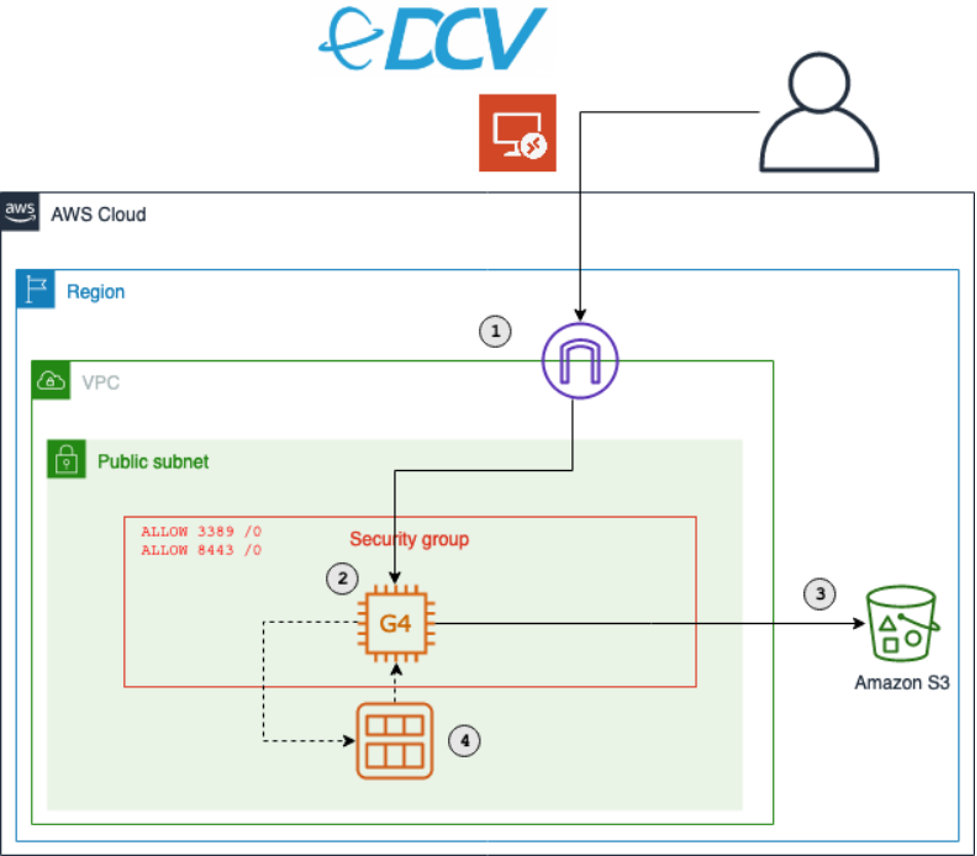
Architecture Overview
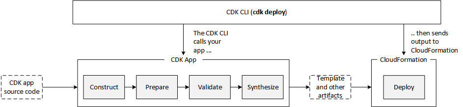
The following architecture shows the overview of the solution which will be built with the code provided through Github.

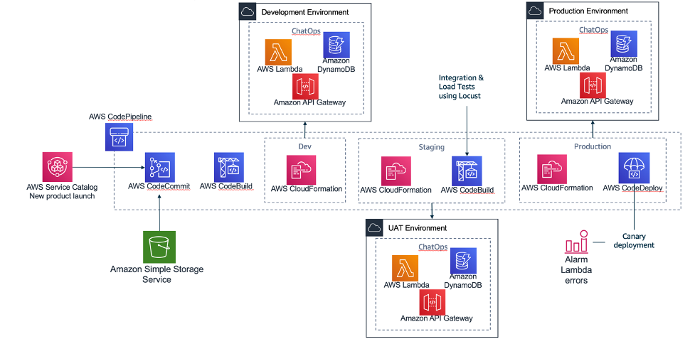
The multi-environment pipeline is building 3 environments (Dev, Staging, Production) with different quality gates to push changes on this solution from a “Development Environment” up to a “Production environment”. This will make sure that your AWS ChatBot and the account vending is scalable and fully functional before you release it to production and make it available to your end-users.
- AWS Code Commit: There are two repositories used, one repository where Amazon Lex bot is created through a Java-Lambda function and installed in STEP 1. And one for the Amazon Lex bot APIs that are running and capturing the Account vending requests behind API Gateway and then communicating with the Amazon Lex Bot.
- AWS Code Pipeline: It integrates CodeCommit and CodeBuild and CodeDeploy, to be manage your release pipelines moving from Dev to Production.
- AWS Code Build: Each different activity executed inside the pipeline is a CodeBuild activity. Inside the source code repository there are different files with the prefix buildspec-. Each of these files contains the exact commands that the code build must execute on each of the stages: build/test.
- AWS Code Deploy: Tthis is an AWS service that manages the deployment of the serverless application stack. In this solution it implements a canary deployment where in the first minute we switch 10% of the requests to the new version of it which will allow to test the scaling of the solution. (CodeDeployDefaultLambdaCanary10Percent5Minutes)
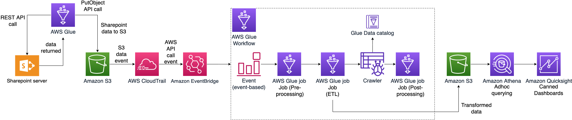
AWS ControlTower Account Vending integration and ChatOps bot architecture

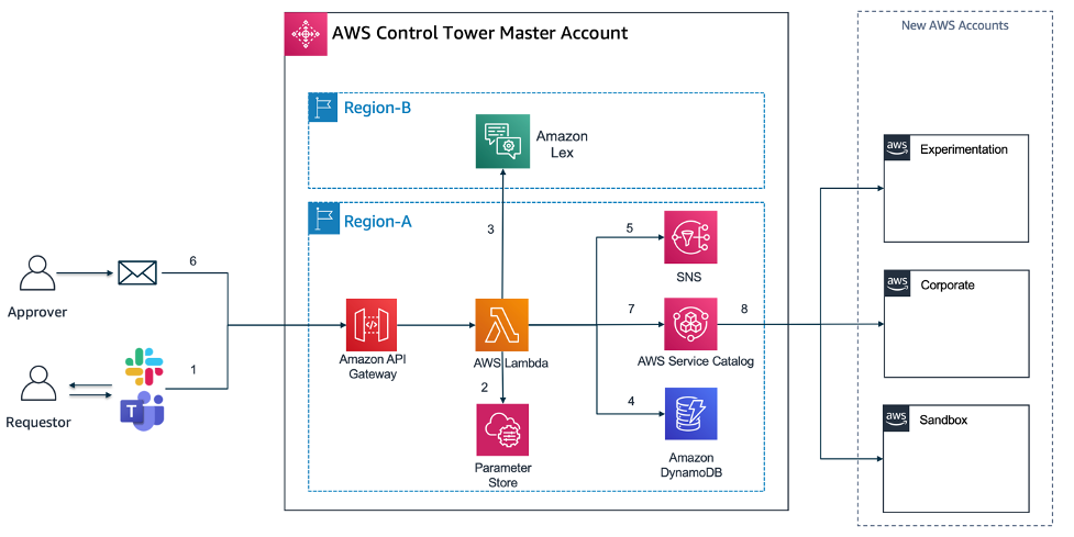
The actual Serverless Application architecture built with Amazon Lex and the Application code in Lambda accessible through Amazon API Gateway, which will allow you to integrate this solution with almost any front-end (Slack, MS Teams, Website).
- Amazon Lex: With Amazon Lex, the same deep learning technologies that power Amazon Alexa are now available to any developer, enabling you to quickly and easily build sophisticated, natural language, conversational bots (“chatbots”). As Amazon lex is not available yet in all AWS regions that currently AWS Control Tower is supported, it may be that you want to deploy Amazon Lex in another region than you have AWS Control Tower deployed.
- Amazon API Gateway / AWS Lambda: The API Gateway is used as a central entry point for the Lambda functions (AccountVendor) that are capturing the Account vending requests from a frontend (e.g. Slack or Website). As Lambda functions can not be exposed directly as a REST service, they need a trigger which in this case API Gateway does.
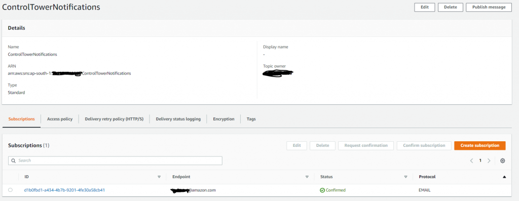
- Amazon SNS: Amazon Simple Notification Service (Amazon SNS) is a fully managed messaging service. SNS is used to send notifications via e-mail channel to an approver mailbox.
- Amazon DynamoDB: Amazon DynamoDB is a key-value and document database that delivers single-digit millisecond performance at any scale. It’s a fully managed, multi-region, multi-active, durable database. Amazon DynamoDB will store the Account vending requests from the Lambda code that get triggered by the Lex-bot interaction.
Solution Overview and Prerequisites
Solution Overview
Start with building these 2 main components of the Architecture through an automated script. This will be split into “STEP 1”, and “STEP 2” in this walkthrough. “STEP 3” and “STEP 4” will be testing the solution and then integrating the solution with a frontend, in this case we use Slack as an example and also provide you with the Slack App manifest file to build the solution quickly.
- STEP 1) “Install Amazon Lex Bot”: The key part of the left side of the Architecture, the Amazon Lex Bot called (“ChatOps” bot) will be built in a first step, then
- STEP 2) “Build of the multi-environment CI/CD pipeline”: Build and deploy a full load testing DevOps pipeline that will stresstest the Lex bot and its capabilities to answer to requests. This will build the supporting components that are needed to integrate with Amazon Lex and are described below (Amazon API Gateway, AWS Lambda, Amazon DynamoDB, Amazon SNS).
- STEP 3) “Testing the ChatOps Bot”: We will execute some test scripts through Postman, that will trigger Amazon API Gateway and trigger a sample Account request that will require a feedback from the ChatOps Lex Bot.
- STEP 4) “Integration with Slack”: The final step is an end-to-end integration with an communication platform solution such as Slack.
The DevOps pipeline (using CodePipeline, CodeCommit, CodeBuild and CodeDeploy) is automatically triggered when the stack is deployed and the AWS CodeCommit repository is created inside the account. The pipeline builds the Amazon Lex ChatOps bot from the source code. The Step 2 integrates the surrounding components with the ChatOps Lex bot in 3 different environments: Dev/Staging/Prod. In addition to that, we use canary deployment to promote updates in the lambda code from the AWS CodeCommit repository. During the canary deployment we implemented the rollback procedure using a log metric filter that scans the word Exception inside the log file in CloudWatch. When the word is found, an alarm is triggered and deployment is automatically rolled back. Usually, the rollback will occur automatically during the load test phase. This would prevent faulty code from being promoted into the production environment.
Prerequisites
For this walkthrough, you should have the following prerequisites ready. What you’ll need:
- An AWS account
- A ready AWS ControlTower deployment (needs 3 AWS Accounts/e-mail addresses)
- AWS Cloud9 IDE or a development environment with access to download/run the scripts provided through Github
- You need to log into the AWS Control Tower management account with AWSAdministratorAccess role if using AWS SSO or equivalent permissions if you are using other federations.
Walkthrough
To get started, you can use Cloud9 IDE or log into your AWS SSO environment within AWS Control Tower.
- Prepare: Set up the sample solution
Log in to your AWS account and open Cloud9.
1.1. Clone the GitHub repository to your Cloud9 environment.
The complete solution can be found at the GitHub repository here. The actual deployment and build are scripted in shell, but the Serverless code is in Java and uses Amazon Serverless services to build this solution (Amazon API Gateway, Amazon DynamoDB, Amazon SNS).
git clone https://github.com/aws-samples/multi-environment-chatops-bot-for-controltower
- STEP 1: Install Amazon Lex Bot
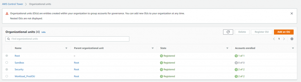
Amazon Lex is currently not deployable natively with Amazon CloudFormation. Therefore the solution is using a custom Lambda resource in Amazon CloudFormation to create the Amazon Lex bot. We will create the Lex bot, along some sample utterances, three custom slots (Account Type, Account E-Mail and Organizational OU) and one main intent (“Control Tower Account Vending Intent”) to capture the request to trigger an AWS Account vending process.
2.1. Start the script, “deploy.sh” and provide the below inputs. Select a project name. You can override it if you wan’t to choose a custom name and select the bucket name accordingly (we recommend to use the default names)
./deploy.sh
Choose a project name [chatops-lex-bot-xyz]:
Choose a bucket name for source code upload [chatops-lex-bot-xyz]:
2.2. To confirm, double check the AWS region you have specificed.
Attention: Make sure you have configured your AWS CLI region! (use either 'aws configure' or set your 'AWS_DEFAULT_REGION' variable).
Using region from $AWS_DEFAULT_REGION: eu-west-1
2.3. Then, make sure you choose the region where you want to install Amazon Lex (make sure you use an available AWS region where Lex is available), or use the default and leave empty. The Amazon Lex AWS region can be different as where you have AWS ControlTower deployed.
Choose a region where you want to install the chatops-lex-bot [eu-west-1]:
Using region eu-west-1
2.4. The script will create a new S3 bucket in the specified region in order to upload the code to create the Amazon Lex bot.
Creating a new S3 bucket on eu-west-1 for your convenience...
make_bucket: chatops-lex-bot-xyz
Bucket chatops-lex-bot-xyz successfully created!
2.5. We show a summary of the bucket name and the project being used.
Using project name................chatops-lex-bot-xyz
Using bucket name.................chatops-lex-bot-xyz
2.6 Make sure that if any of these names or outputs are wrong, you can still stop here by pressing Ctrl+c.
If these parameters are wrong press ctrl+c to stop now...
2.7 The script will upload the source code to the S3 bucket specified, you should see a successful upload.
Waiting 9 seconds before continuing
upload: ./chatops-lex-bot-xyz.zip to s3://chatops-lex-bot-xyz/chatops-lex-bot-xyz.zip
2.8 Then, the script will trigger an aws cloudformation package command, that will use the uploaded zip file, reference it and generate a ready CloudFormation yml file for deployment. The output of the generated package-file (devops-packaged.yml) will be stored locally and used to executed the aws cloudformation deploy command.
Successfully packaged artifacts and wrote output template to file devops-packaged.yml.
Note: You can ignore this part below as the shell script will execute the “aws cloudformation deploy” command for you.
Execute the following command to deploy the packaged template
aws cloudformation deploy --template-file devops-packaged.yml --stack-name <YOUR STACK NAME>
2.9 The AWS CloudFormation scripts should be running in the background
Waiting for changeset to be created..
Waiting for stack create/update to complete
Successfully created/updated stack - chatops-lex-bot-xyz-cicd
2.10 Once you see the successful output of the CloudFormation script “chatops-lex-bot-xyz-cicd”, everything is ready to continue.
------------------------------------------
ChatOps Lex Bot Pipeline is installed
Will install the ChatOps API as an Add-On to the Vending Machine
------------------------------------------
2.11 Before we continue, confirm the output of the AWS CloudFormation called “chatops-lex-bot-xyz-cicd”. You should find three outputs from the CloudFormation template.
- A CodePipeline, CodeCommit Repository with the same naming convention (chatops-lex-bot-xyz), and a CodeBuild execution with one stage (Prod). The execution of this pipeline should show as “Succeeded” within CodePipeline.
- As a successful result of the execution of the Pipeline, you should find another CloudFormation that was triggered, which you should find in the output of CodeBuild or the CloudFormation Console (chatops-lex-bot-xyz-Prod).
- The created resource of this CloudFormation will be the Lambda function (chatops-lex-bot-xyz-Prod-AppFunction-abcdefgh) that will create the Amazon Lex Bot. You can find the details in Amazon Lambda in the Mgmt console. For more information on CloudFormation and custom resources, see the CloudFormation documentation.
- You can find the successful execution in the CloudWatch Logs:
Adding Slot Type:: AccountTypeValues
Adding Slot Type:: AccountOUValues
Adding Intent:: AWSAccountVending
Adding LexBot:: ChatOps
Adding LexBot Alias:: AWSAccountVending
- Check if the Amazon Lex bot has been created in the Amazon Lex console, you should see an Amazon Lex bot called “ChatOps” with the status “READY”.
2.12. This means you have successfully installed the ChatOps Lex Bot. You can now continue with STEP 2.
- STEP 2. Build of the multi-environment CI/CD pipeline
In this section, we will finalize the set up by creating a full CI/CD Pipeline, the API Gateway and Lambda functions that can capture requests for Account creation (AccountVendor) and interact with Amazon Lex, and a full testing cycle to do a Dev-Staging-Production build pipeline that does a stress test on the whole set of Infrastructure created.
3.1 You should see the same name of the bucket and project as used previously. If not, please override the input here. Otherwise, leave empty (we recommend to use the default names).
Choose a bucket name for source code upload [chatops-lex-xyz]:
3.2. This means that the Amazon Lex Bot was successfully deployed, and we just confirm the deployed AWS region.
ChatOps-Lex-Bot is already deployed in region eu-west-1
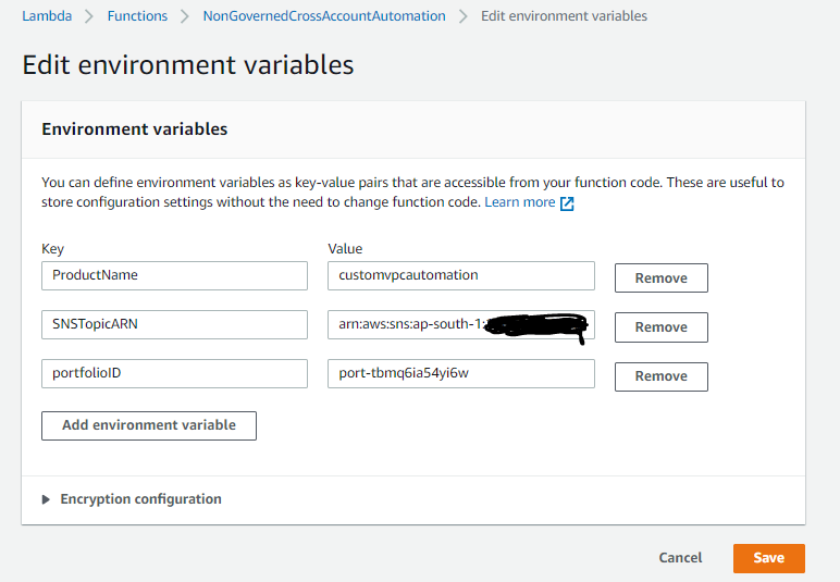
3.3 Please specify a mailbox that you have access in order to approve new ChatOps (e.g. Account vending) vending requests as a manual approver step.
Choose a mailbox to receive approval e-mails for new accounts: [email protected]
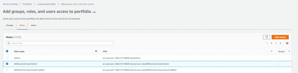
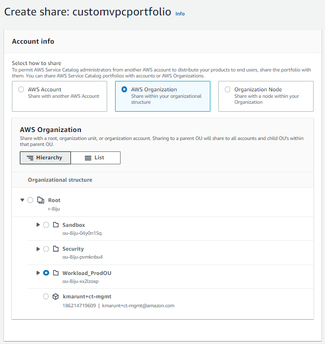
3.4 Make sure you have the right AWS region where AWS Control Tower has deployed its Account Factory Portfolio product in Service Catalog (to double check you can log into AWS Service Catalog and confirm that you see the AWS Control Tower Account Factory)
Choose the AWS region where your vending machine is installed [eu-west-1]:
Using region eu-west-1
Creating a new S3 bucket on eu-west-1 for your convenience...
{
"Location": "http://chatops-lex-xyz.s3.amazonaws.com/"
}
Bucket chatops-lex-xyz successfully created!
3.5 Now the script will identify if you have Control Tower deployed and if it can identify the Control Tower Account Factory Product.
Trying to find the AWS Control Tower Account Factory Portfolio
Using project name....................chatops-lex-xyz
Using bucket name.....................chatops-lex-xyz
Using mailbox for approvals...........approvermail+chatops-lex-bot-xyz@yourdomain.com
Using lexbot region...................eu-west-1
Using service catalog portfolio-id....port-abcdefghijklm
If these parameters are wrong press ctrl+c to stop now…
3.6 If something is wrong or has not been set and you see an empty line for any of the, stop here and press ctr+c. Check the Q&A section if you might have missed some errors previously. These values need to be filled to proceed.
Waiting 1 seconds before continuing
[INFO] Scanning for projects...
[INFO] Building Serverless Jersey API 1.0-SNAPSHOT
3.7 You should see a “BUILD SUCCESS” message.
[INFO] BUILD SUCCESS
[INFO] Total time: 0.190 s
3.8 Then the package built locally will be uploaded to the S3 bucket, and then again prepared for Amazon CloudFormation to package- and deploy.
upload: ./chatops-lex-xyz.zip to s3://chatops-lex-xyz/chatops-lex-xyz.zip
Successfully packaged artifacts and wrote output template to file devops-packaged.yml.
Execute the following command to deploy the packaged template
aws cloudformation deploy --template-file devops-packaged.yml --stack-name <YOUR STACK NAME>
3.9 You can neglect the above message, as the shell script will execute the Cloudformation API for you. The AWS CloudFormation scripts should be running in the background, and you can double check in the AWS Mgmt Console.
Waiting for changeset to be created..
Waiting for stack create/update to complete
Successfully created/updated stack - chatops-lex-xyz-cicd
------------------------------------------
ChatOps Lex Pipeline and Chatops Lex Bot Pipelines successfully installed
------------------------------------------
3.10 This means that the Cloud Formation scripts have executed successfully. Lets confirm in the Amazon CloudFormation console, and in Code Pipeline if we have a successful outcome and full test-run of the CICD pipeline. To remember, have a look at the AWS Architecture overview and the resources / components created.
You should find the successful Cloud Formation artefacts named:
- chatops-lex-xyz-cicd: This is the core CloudFormation that we created and uploaded that built a full CI/CD pipeline with three phases (DEV/STAGING/PROD). All three stages will create a similar set of AWS resources (e.g. Amazon API Gateway, AWS Lambda, Amazon DynamoDB), but only the Staging phase will run an additional Load-Test prior to doing the production release.
- chatops-lex-xyz-DEV: A successful build, creation and deployment of the DEV environment.
- chatops-lex-xyz-STAGING: The staging phase will run a set of load tests, for a full testing and through io (an open-source load testing framework)
- chatops-lex-xyz-PROD: A successful build, creation and deployment of the Production environment.
3.11 For further confirmation, you can check the Lambda-Functions (chatops-lex-xyz-pipeline-1-Prod-ChatOpsLexFunction-), Amazon DynamoDB (chatops-lex-xyz-pipeline-1_account_vending_) and Amazon SNS (chatops-lex-xyz-pipeline-1_aws_account_vending_topic_Prod) if all the resources as shown in the Architecture picture have been created.
Within Lambda and/or Amazon API Gateway, you will find the API Gateway execution endpoints, same as in the Output section from CloudFormation:
- ApiUrl: https://apiId.execute-api.eu-west-1.amazonaws.com/Prod/account
- ApiApproval https://apiId.execute-api.eu-west-1.amazonaws.com/Prod/account/confirm
3.11 This means you have successfully installed the Amazon Lex ChatOps bot, and the surrounding test CI/CD pipeline. Make sure you have accepted the SNS subscription confirmation.
AWS Notification - Subscription Confirmation
You have chosen to subscribe to the topic:
arn:aws:sns:eu-west-1:12345678901:chatops-lex-xyz-pipeline_aws_account_vending_topic_Prod
To confirm this subscription, click or visit the link below (If this was in error no action is necessary)
- STEP 3: Testing the ChatOps Bot
In this section, we provided a test script to test if the Amazon Lex Bot is up and if Amazon API Gateway/Lambda are correctly configured to handle the requests.
4.1 Use the Postman script under the /test folder postman-test.json, before you start integrating this solution with a Chat or Web- frontend such as Slack or a custom website in Production.
4.2. You can import the JSON file into Postman and execute a RESTful test call to the API Gateway endpoint.
4.3 Once the script is imported in Postman, you should execute the two commands below and replace the HTTP URL of the two requests (Vending API and Confirmation API) by the value of APIs recently created in the Production environment. Alternatively, you can also access these values directly from the Output tab in the CloudFormation stack with a name similar to chatops-lex-xyz-Prod:
aws cloudformation describe-stacks --query "Stacks[0].Outputs[?OutputKey=='ApiUrl'].OutputValue" --output text
aws cloudformation describe-stacks --query "Stacks[0].Outputs[?OutputKey=='ApiApproval'].OutputValue" --output text
4.4 Execute an API call against the PROD API
- Use the Amazon API Gateaway endpoint to trigger a REST call against the endpoint, an example would be https://apiId.execute-api.eu-west-1.amazonaws.com/Prod/account/. Make sure you change the “apiId” with your Amazon Gateway API ID endpoint found in the above sections (CloudFormation Output or within the Lambda), see here the start of the parameters that you have to change in the postman-test.json file:
"url": {
"raw": "https://apiId.execute-api.us-east-1.amazonaws.com/Prod/account",
"protocol": "https",
- Request Input, fill out and update the values on each of the JSON sections:
{ “UserEmail”: “[email protected]”, “UserName”:“TestUser-Name”, “UserLastname”: “TestUser-LastName”, “UserInput”: “Hi, I would like a new account please!”}
- If the test response is SUCCESSFUL, you should see the following JSON as a return:
{"response": "Hi TestUser-Name, what account type do you want? Production or Sandbox?","initial-params": "{\"UserEmail\": \"[email protected]\",\"UserName\":\"TestUser-Name\",\"UserLastname\": \"TestUser-LastName\",\"UserInput\": \"Hi, I would like a new account please!\"}"}
4.5 Test the “confirm” action. To confirm the Account vending request, you can easily execute the /confirm API, which is similar to if you would confirm the action through the e-mail confirmation that you receive via Amazon SNS.
Make sure you change the following sections in Postman (Production-Confirm-API) and use the ApiApproval-apiID that has the /confirm path.
https://apiId.execute-api.eu-west-1.amazonaws.com/Prod/account/confirm
- STEP 4: Slack Integration Example
We will demonstrate you how to integrate with a Slack channel but any other request portal (Jira), Website or App that allows REST API integrations (e.g. Amazon Chime) could be used for this.
5.1 Use the attached YAML slack App manifest file to create a new Slack Application within your Organization. Go to “https://api.slack.com/apps?new_app=1” and choose “Create New App”.
5.2 Choose the “From an app manifest” to create a new Slack App and paste the sample code from the /test folder slack-app-manifest.yml .
- Note: Make sure you first overwrite the request_url parameter for your Slack App that will point to the Production API Gateway endpoint.
request_url: https://apiId.execute-api.us-east-1.amazonaws.com/Prod/account"
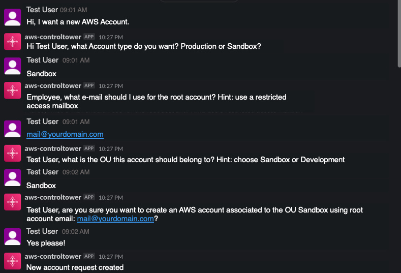
5.3 Choose to deploy and re-install the Slack App to your workspace and then access the ChatBot Application within your Slack workspace. If everything is successful, you can see a working Serverless ChatBot as shown below.

Conclusion and Cleanup
Conclusion
In this blog post, you have learned how to create a multi-environment CICD pipeline that builds a fully Serverless AWS account vending solution using an AI powered Amazon Lex bot integrated with AWS Control Tower Account Factory. This solution will help you enable standardized account vending on AWS through an easy way by exposing a ChatBot to your AWS consumers coming from various channels. This solution can be extended with AWS ServiceCatalog to allow to launch not just AWS accounts, but almost any AWS Service by using IaC (CloudFormation) templates provided through the CCoE Ops and Architecture teams.
Cleanup
For a proper cleanup, you can just go into AWS CloudFormation and choose the deployed Stacks and choose to “delete Stack”. If you incur issues while deleting, see below troubleshooting solutions for a fix. Also make sure you delete your integration Apps (e.g. Slack) for a full cleanup.
Troubleshooting
- An error occurred (BucketAlreadyOwnedByYou) when calling the CreateBucket operation: Your previous request to create the named bucket succeeded and you already own it.
Solution: Make sure you use a distinct name for the S3 bucket used in this project, for the Amazon Lex Bot and the CICD pipeline
- When you delete and rollback of the CloudFormation stacks and you get an error (Code: 409; Error Code: BucketNotEmpty).
Solution: Delete the S3 build bucket and its content “delete permanently” and then delete the associated CloudFormation stack that has created the CICD pipeline.


 Hammad Ausaf is a Sr Solutions Architect in the M&E space. He is a passionate builder and strives to provide the best solutions to AWS customers.
 Andrew Lee is a Solutions Architect on the Snap Account, and is based in Los Angeles, CA.


 Syed Ali Abbas Gardezi is a Sr. Solution Architect for AWS based in London, United Kingdom. He works with AWS GSI Partners architecting, designing and implementing various large-scale IT solution. Before joining AWS he worked in several Architecture roles in a tier 1 financial organisation in London.