Tag Archives: Amazon Simple Storage Services (S3)

Analyze Fraud Transactions using Amazon Fraud Detector and Amazon Athena

Post Syndicated from Raghavarao Sodabathina original https://aws.amazon.com/blogs/architecture/analyze-fraud-transactions-using-amazon-fraud-detector-and-amazon-athena/

Organizations with online businesses have to be on guard constantly for fraudulent activity, such as fake accounts or payments made with stolen credit cards. One way they try to identify fraudsters is by using fraud detection applications. Some of these applications use machine learning (ML).

A common challenge with ML is the need for a large, labeled dataset to create ML models to detect fraud. You will also need the skill set and infrastructure to build, train, deploy, and scale your ML model.

In this post, I discuss how to perform fraud detection on a batch of many events using Amazon Fraud Detector. Amazon Fraud Detector is a fully managed service that can identify potentially fraudulent online activities. These can be situations such as the creation of fake accounts or online payment fraud. Unlike general-purpose ML packages, Amazon Fraud Detector is designed specifically to detect fraud. You can analyze fraud transaction prediction results by using Amazon Athena and Amazon QuickSight. I will explain how to review fraud using Amazon Fraud Detector and Amazon SageMaker built-in algorithms.

Batch fraud prediction use cases

You can use a batch predictions job in Amazon Fraud Detector to get predictions for a set of events that do not require real-time scoring. You may want to generate fraud predictions for a batch of events. These might be payment fraud, account take over or compromise, and free tier misuse while performing an offline proof-of-concept. You can also use batch predictions to evaluate the risk of events on an hourly, daily, or weekly basis depending upon your business need.

Batch fraud insights using Amazon Fraud Detector

Organizations such as ecommerce companies and credit card companies use ML to detect the fraud. Some of the most common types of fraud include email account compromise (personal or business), new account fraud, and non-payment or non-delivery (which includes compromised card numbers).

Amazon Fraud Detector automates the time-consuming and expensive steps to build, train, and deploy an ML model for fraud detection. Amazon Fraud Detector customizes each model it creates to your dataset, making the accuracy of models higher than current one-size-fits-all ML solutions. And because you pay only for what you use, you can avoid large upfront expenses.

If you want to analyze fraud transactions after the fact, you can perform batch fraud predictions using Amazon Fraud Detector. Then you can store fraud prediction results in an Amazon S3 bucket. Amazon Athena helps you analyze the fraud prediction results. You can create fraud prediction visualization dashboards using Amazon QuickSight.

The following diagram illustrates how to perform fraud predictions for a batch of events and analyze them using Amazon Athena.

Figure 1. Example architecture for analyzing fraud transactions using Amazon Fraud Detector and Amazon Athena

Figure 1. Example architecture for analyzing fraud transactions using Amazon Fraud Detector and Amazon Athena

The architecture flow follows these general steps:

  1. Create and publish a detector. First create and publish a detector using Amazon Fraud Detector. It should contain your fraud prediction model and rules. For additional details, see Get started (console).
  2. Create an input Amazon S3 bucket and upload your CSV file. Prepare a CSV file that contains the events you want to evaluate. Then upload your CSV file into the input S3 bucket. In this file, include a column for each variable in the event type associated with your detector. In addition, include columns for EVENT_ID, ENTITY_ID, EVENT_TIMESTAMP, ENTITY_TYPE. Refer to Amazon Fraud Detector batch input and output files for more details. Read Create a variable for additional information on Amazon Fraud Detector variable data types and formatting.
  3. Create an output Amazon S3 bucket. Create an output Amazon S3 bucket to store your Amazon Fraud Detector prediction results.
  4. Perform a batch prediction. You can use a batch predictions job in Amazon Fraud Detector to get predictions for a set of events that do not require real-time scoring. Read more here about Batch predictions.
  5. Review your prediction results. Review your results in the CSV file that is generated and stored in the Amazon S3 output bucket.
  6. Analyze your fraud prediction results.
    • After creating a Data Catalog by using AWS Glue, you can use Amazon Athena to analyze your fraud prediction results with standard SQL.
    • You can develop user-friendly dashboards to analyze fraud prediction results using Amazon QuickSight by creating new datasets with Amazon Athena as your data source.

Fraud detection using Amazon SageMaker

The Amazon Web Services (AWS) Solutions Implementation, Fraud Detection Using Machine Learning, enables you to run automated transaction processing. This can be on an example dataset or your own dataset. The included ML model detects potentially fraudulent activity and flags that activity for review. The diagram following presents the architecture you can automatically deploy using the solution’s implementation guide and accompanying AWS CloudFormation template.

SageMaker provides several built-in machine learning algorithms that you can use for a variety of problem types. This solution leverages the built-in Random Cut Forest algorithm for unsupervised learning and the built-in XGBoost algorithm for supervised learning. In the SageMaker Developer Guide, you can see how Random Cut Forest and XGBoost algorithms work.

Figure 2. Fraud detection using machine learning architecture on AWS

Figure 2. Fraud detection using machine learning architecture on AWS

This architecture can be segmented into three phases.

  1. Develop a fraud prediction machine learning model. The AWS CloudFormation template deploys an example dataset of credit card transactions contained in an Amazon Simple Storage Service (Amazon S3) bucket. An Amazon SageMaker notebook instance with different ML models will be trained on the dataset.
  2. Perform fraud prediction. The solution also deploys an AWS Lambda function that processes transactions from the example dataset. It invokes the two SageMaker endpoints that assign anomaly scores and classification scores to incoming data points. An Amazon API Gateway REST API initiates predictions using signed HTTP requests. An Amazon Kinesis Data Firehose delivery stream loads the processed transactions into another Amazon S3 bucket for storage. The solution also provides an example of how to invoke the prediction REST API as part of the Amazon SageMaker notebook.
  3. Analyze fraud transactions. Once the transactions have been loaded into Amazon S3, you can use analytics tools and services for visualization, reporting, ad-hoc queries, and more detailed analysis.

By default, the solution is configured to process transactions from the example dataset. To use your own dataset, you must modify the solution. For more information, see Customization.

Conclusion

In this post, we showed you how to analyze fraud transactions using Amazon Fraud Detector and Amazon Athena. You can build fraud insights using Amazon Fraud Detector and Amazon SageMaker built-in algorithms Random Cut Forest and XGBoost. With the information in this post, you can build your own fraud insights models on AWS. You’ll be able to detect fraud faster. Finally, you’ll be able to solve a variety of fraud types. These can be new account fraud, online transaction fraud, and fake reviews, among others.

Read more and get started on building fraud detection models on AWS.

Choosing Your VPC Endpoint Strategy for Amazon S3

Post Syndicated from Jeff Harman original https://aws.amazon.com/blogs/architecture/choosing-your-vpc-endpoint-strategy-for-amazon-s3/

This post was co-written with Anusha Dharmalingam, former AWS Solutions Architect.

Must your Amazon Web Services (AWS) application connect to Amazon Simple Storage Service (S3) buckets, but not traverse the internet to reach public endpoints? Must the connection scale to accommodate bandwidth demands? AWS offers a mechanism called VPC endpoint to meet these requirements. This blog post provides guidance for selecting the right VPC endpoint type to access Amazon S3. A VPC endpoint enables workloads in an Amazon VPC to connect to supported public AWS services or third-party applications over the AWS network. This approach is used for workloads that should not communicate over public networks.

When a workload architecture uses VPC endpoints, the application benefits from the scalability, resilience, security, and access controls native to AWS services. Amazon S3 can be accessed using an interface VPC endpoint powered by AWS PrivateLink or a gateway VPC endpoint. To determine the right endpoint for your workloads, we’ll discuss selection criteria to consider based on your requirements.

VPC endpoint overview

A VPC endpoint is a virtual scalable networking component you create in a VPC and use as a private entry point to supported AWS services and third-party applications. Currently, two types of VPC endpoints can be used to connect to Amazon S3: interface VPC endpoint and gateway VPC endpoint.

When you configure an interface VPC endpoint, an elastic network interface (ENI) with a private IP address is deployed in your subnet. An Amazon EC2 instance in the VPC can communicate with an Amazon S3 bucket through the ENI and AWS network. Using the interface endpoint, applications in your on-premises data center can easily query S3 buckets over AWS Direct Connect or Site-to-Site VPN. Interface endpoint supports a growing list of AWS services. Consult our documentation to find AWS services compatible with interface endpoints powered by AWS PrivateLink.

Gateway VPC endpoints use prefix lists as the IP route target in a VPC route table. This routes traffic privately to Amazon S3 or Amazon DynamoDB. An EC2 instance in a VPC without internet access can still directly read from and/or write to an Amazon S3 bucket. Amazon DynamoDB and Amazon S3 are the services currently accessible via gateway endpoints.

Your internal security policies may have strict rules against communication between your VPC and the internet. To maintain compliance with these policies, you can use VPC endpoint to connect to AWS public services like Amazon S3. To control user or application access to the VPC endpoint and the resources it supports, you can use an AWS Identity and Access Management (AWS IAM) resource policy. This will separately secure the VPC endpoint and accessible resources.

Selecting gateway or interface VPC endpoints

With both interface endpoint and gateway endpoint available for Amazon S3, here are some factors to consider as you choose one strategy over the other.

  • Cost: Gateway endpoints for S3 are offered at no cost and the routes are managed through route tables. Interface endpoints are priced at $0.01/per AZ/per hour. Cost depends on the Region, check current pricing. Data transferred through the interface endpoint is charged at $0.01/per GB (depending on Region).
  • Access pattern: S3 access through gateway endpoints is supported only for resources in a specific VPC to which the endpoint is associated. S3 gateway endpoints do not currently support access from resources in a different Region, different VPC, or from an on-premises (non-AWS) environment. However, if you’re willing to manage a complex custom architecture, you can use proxies. In all those scenarios, where access is from resources external to VPC, S3 interface endpoints access S3 in a secure way.
  • VPC endpoint architecture: Some customers use centralized VPC endpoint architecture patterns. This is where the interface endpoints are all managed in a central hub VPC for accessing the service from multiple spoke VPCs. This architecture helps reduce the complexity and maintenance for multiple interface VPC endpoints across different VPCs. When using an S3 interface endpoint, you must consider the amount of network traffic that would flow through your network from spoke VPCs to hub VPC. If the network connectivity between spoke and hub VPCs are set up using transit gateway, or VPC peering, consider the data processing charges (currently $0.02/GB). If VPC peering is used, there is no charge for data transferred between VPCs in the same Availability Zone. However, data transferred between Availability Zones or between Regions will incur charges as defined in our documentation.

In scenarios where you must access S3 buckets securely from on-premises or from across Regions, we recommend using an interface endpoint. If you chose a gateway endpoint, install a fleet of proxies in the VPC to address transitive routing.

Figure 1. VPC endpoint architecture

Figure 1. VPC endpoint architecture

  • Bandwidth considerations: When setting up an interface endpoint, choose multiple subnets across multiple Availability Zones to implement high availability. The number of ENIs should equal to number of subnets chosen. Interface endpoints offer a throughput of 10 Gbps per ENI with a burst capability of 40 Gbps. If your use case requires higher throughput, contact AWS Support.

Gateway endpoints are route table entries that route your traffic directly from the subnet where traffic is originating to the S3 service. Traffic does not flow through an intermediate device or instance. Hence, there is no throughput limit for the gateway endpoint itself. The initial setup for gateway endpoints consists in specifying the VPC route tables you would like to use to access the service. Route table entries for the destination (prefix list) and target (endpoint ID) are automatically added to the route tables.

The two architectural options for creating and managing endpoints are:

Single VPC architecture

Using a single VPC, we can configure:

  • Gateway endpoints for VPC resources to access S3
  • VPC interface endpoint for on-premises resources to access S3

The following architecture shows the configuration on how both can be set up in a single VPC for access. This is useful when access from within AWS is limited to a single VPC while still enabling external (non-AWS) access.

Figure 2. Single VPC architecture

Figure 2. Single VPC architecture

DNS configured on-premises will point to the VPC interface endpoint IP addresses. It will forward all traffic from on-premises to S3 through the VPC interface endpoint. The route table configured in the subnet will ensure that any S3 traffic originating from the VPC will flow to S3 using gateway endpoints.

Multi-VPC centralized architecture

In a hub and spoke architecture that centralizes S3 access for multi-Region, cross-VPC, and on-premises workloads, we recommend using an interface endpoint in the hub VPC. The same pattern would also work in multi-account/multi-region design where multiple VPCs require access to centralized buckets.

Note: Firewall appliances that monitor east-west traffic will experience increased load with the Multi-VPC centralized architecture. It may be necessary to use the single VPC endpoint design to reduce impact to firewall appliances.

Figure 3. Multi-VPC centralized architecture

Figure 3. Multi-VPC centralized architecture

Conclusion

Based on preceding considerations, you can choose to use a combination of gateway and interface endpoints to meet your specific needs. Depending on the account structure and VPC setup, you can support both types of VPC endpoints in a single VPC by using a shared VPC architecture.

With AWS, you can choose between two VPC endpoint types (gateway endpoint or interface endpoint) to securely access your S3 buckets using a private network. In this blog, we showed you how to select the right VPC endpoint using criteria like VPC architecture, access pattern, and cost. To learn more about VPC endpoints and improve the security of your architecture, read Securely Access Services Over AWS PrivateLink.

Intelligently Search Media Assets with Amazon Rekognition and Amazon ES

Post Syndicated from Sridhar Chevendra original https://aws.amazon.com/blogs/architecture/intelligently-search-media-assets-with-amazon-rekognition-and-amazon-es/

Media assets have become increasingly important to industries like media and entertainment, manufacturing, education, social media applications, and retail. This is largely due to innovations in digital marketing, mobile, and ecommerce.

Successfully locating a digital asset like a video, graphic, or image reduces costs related to reproducing or re-shooting. An efficient search engine is critical to quickly delivering something like the latest fashion trends. This in turn increases customer satisfaction, builds brand loyalty, and helps increase businesses’ online footprints, ultimately contributing towards revenue.

This blog post shows you how to build automated indexing and search functions using AWS serverless managed artificial intelligence (AI)/machine learning (ML) services. This architecture provides high scalability, reduces operational overhead, and scales out/in automatically based on the demand, with a flexible pay-as-you-go pricing model.

Automatic tagging and rich metadata with Amazon ES

Asset libraries for images and videos are growing exponentially. With Amazon Elasticsearch Service (Amazon ES), this media is indexed and organized, which is important for efficient search and quick retrieval.

Adding correct metadata to digital assets based on enterprise standard taxonomy will help you narrow down search results. This includes information like media formats, but also richer metadata like location, event details, and so forth. With Amazon Rekognition, an advanced ML service, you do not need to tag and index these media assets. This automatic tagging and organization frees you up to gain insights like sentiment analysis from social media.

Figure 1 is tagged using Amazon Rekognition. You can see how rich metadata (Apparel, T-Shirt, Person, and Pills) is extracted automatically. Without Amazon Rekognition, you would have to manually add tags and categorize the image. This means you could only do a keyword search on what’s manually tagged. If the image was not tagged, then you likely wouldn’t be able to find it in a search.

Figure 1. An image tagged automatically with Amazon Rekognition

Figure 1. An image tagged automatically with Amazon Rekognition

Data ingestion, organization, and storage with Amazon S3

As shown in Figure 2, use Amazon Simple Storage Service (Amazon S3) to store your static assets. It provides high availability and scalability, along with unlimited storage. When you choose Amazon S3 as your content repository, multiple data providers are configured for data ingestion for future consumption by downstream applications. In addition to providing storage, Amazon S3 lets you organize data into prefixes based on the event type and captures S3 object mutations through S3 event notifications.

Figure 2. Solution overview diagram

Figure 2. Solution overview diagram

S3 event notifications are invoked for a specific prefix, suffix, or combination of both. They integrate with Amazon Simple Queue Service (Amazon SQS), Amazon Simple Notification Service (Amazon SNS), and AWS Lambda as targets. (Refer to the Amazon S3 Event Notifications user guide for best practices). S3 event notification targets vary across use cases. For media assets, Amazon SQS is used to decouple the new data objects ingested into S3 buckets and downstream services. Amazon SQS provides flexibility over the data processing based on resource availability.

Data processing with Amazon Rekognition

Once media assets are ingested into Amazon S3, they are ready to be processed. Amazon Rekognition determines the entities within each asset. Amazon Rekognition then extracts the entities in JSON format and assigns a confidence score.

If the confidence score is below the defined threshold, use Amazon Augmented AI (A2I) for further review. A2I is an ML service that helps you build the workflows required for human review of ML predictions.

Amazon Rekognition also supports custom modeling to help identify entities within the images for specific business needs. For instance, a campaign may need images of products worn by a brand ambassador at a marketing event. Then they may need to further narrow their search down by the individual’s name or age demographic.

Using our solution, a Lambda function invokes Amazon Rekognition to extract the entities from the ingested assets. Lambda continuously polls the SQS queue for any new messages. Once a message is available, the Lambda function invokes the Amazon Rekognition endpoint to extract the relevant entities.

The following is a sample output from detect_labels API call in Amazon Rekognition and the transformed output that will be updated to downstream search engine:

{'Labels': [{'Name': 'Clothing', 'Confidence': 99.98137664794922, 'Instances': [], 'Parents': []}, {'Name': 'Apparel', 'Confidence': 99.98137664794922,'Instances': [], 'Parents': []}, {'Name': 'Shirt', 'Confidence': 97.00833129882812, 'Instances': [], 'Parents': [{'Name': 'Clothing'}]}, {'Name': 'T-Shirt', 'Confidence': 76.36670684814453, 'Instances': [{'BoundingBox': {'Width': 0.7963646650314331, 'Height': 0.6813027262687683, 'Left':
0.09593021124601364, 'Top': 0.1719706505537033}, 'Confidence': 53.39663314819336}], 'Parents': [{'Name': 'Clothing'}]}], 'LabelModelVersion': '2.0', 'ResponseMetadata': {'RequestId': '3a561e82-badc-4ba0-aa77-39a13f1bb3a6', 'HTTPStatusCode': 200, 'HTTPHeaders': {'content-type': 'application/x-amz-json-1.1', 'date': 'Mon, 17 May 2021 18:32:27 GMT', 'x-amzn-requestid': '3a561e82-badc-4ba0-aa77-39a13f1bb3a6','content-length': '542', 'connection': 'keep-alive'}, 'RetryAttempts': 0}}

As shown, the Lambda function submits an API call to Amazon Rekognition, where a T-shirt image in .jpeg format is provided as the input. Based on your confidence score threshold preference, Amazon Rekognition will prompt you to initiate a human review using Amazon A2I. It will also prompt you to use Amazon Rekognition Custom Labels to train the custom models. Lambda then identifies and arranges the labels and updates the specified index.

Indexing with Amazon ES

Amazon ES is a managed search engine service that provides enterprise-grade search engine capability for applications. In our solution, assets are searched based on entities that are used as metadata to update the index. Amazon ES is hosted as a public endpoint or a VPC endpoint for secure access within the specified AWS account.

Labels are identified and marked as tags, which are assigned to .jpeg formatted images. The following sample output shows the query on one of the tags issued on an Amazon ES cluster.

Query:

curl-XGET https://<ElasticSearch Endpoint>/<_IndexName>/_search?q=T-Shirt

Output:

{"took":140,"timed_out":false,"_shards":{"total":5,"successful":5,"skipped":0,"failed":0},"hits":{"total":{"value":1,"relation":"eq"},"max_score":0.05460011,"hits":[{"_index":"movies","_type":"_doc","_id":"15","_score":0.05460011,"_source":{"fileName":"s7-1370766_lifestyle.jpg","objectTags":["Clothing","Apparel","Sailor
Suit","Sleeve","T-Shirt","Shirt","Jersey"]}}]}}

In addition to photos, Amazon Rekognition also detects the labels on videos. It can recognize labels and identify characters and entities. These are then added to Amazon ES to enhance search capability. This allows users to skip to specific parts of a video for quick searchability. For instance, a marketer may need images of cashmere sweaters from a fashion show that was streamed and recorded.

Once the raw video clip is identified, it is then converted using Amazon Elastic Transcoder to play back on mobile devices, tablets, web browsers, and connected televisions. Elastic Transcoder is a highly scalable and cost-effective media transcoding service in the cloud. Segmented output renditions are created for delivery using the multiple protocols to compatible devices.

Conclusion

This blog describes AWS services that can be applied to diverse set of use cases for tagging and efficient search of images and videos. You can build automated indexing and search using AWS serverless managed AI/ML services. They provide high scalability, reduce operational overhead, and scale out/in automatically based on the demand, with a flexible pay-as-you-go pricing model.

To get started, use these references to create your own sample architectures:

Implement tenant isolation for Amazon S3 and Aurora PostgreSQL by using ABAC

Post Syndicated from Ashutosh Upadhyay original https://aws.amazon.com/blogs/security/implement-tenant-isolation-for-amazon-s3-and-aurora-postgresql-by-using-abac/

In software as a service (SaaS) systems, which are designed to be used by multiple customers, isolating tenant data is a fundamental responsibility for SaaS providers. The practice of isolation of data in a multi-tenant application platform is called tenant isolation. In this post, we describe an approach you can use to achieve tenant isolation in Amazon Simple Storage Service (Amazon S3) and Amazon Aurora PostgreSQL-Compatible Edition databases by implementing attribute-based access control (ABAC). You can also adapt the same approach to achieve tenant isolation in other AWS services.

ABAC in Amazon Web Services (AWS), which uses tags to store attributes, offers advantages over the traditional role-based access control (RBAC) model. You can use fewer permissions policies, update your access control more efficiently as you grow, and last but not least, apply granular permissions for various AWS services. These granular permissions help you to implement an effective and coherent tenant isolation strategy for your customers and clients. Using the ABAC model helps you scale your permissions and simplify the management of granular policies. The ABAC model reduces the time and effort it takes to maintain policies that allow access to only the required resources.

The solution we present here uses the pool model of data partitioning. The pool model helps you avoid the higher costs of duplicated resources for each tenant and the specialized infrastructure code required to set up and maintain those copies.

Solution overview

In a typical customer environment where this solution is implemented, the tenant request for access might land at Amazon API Gateway, together with the tenant identifier, which in turn calls an AWS Lambda function. The Lambda function is envisaged to be operating with a basic Lambda execution role. This Lambda role should also have permissions to assume the tenant roles. As the request progresses, the Lambda function assumes the tenant role and makes the necessary calls to Amazon S3 or to an Aurora PostgreSQL-Compatible database. This solution helps you to achieve tenant isolation for objects stored in Amazon S3 and data elements stored in an Aurora PostgreSQL-Compatible database cluster.

Figure 1 shows the tenant isolation architecture for both Amazon S3 and Amazon Aurora PostgreSQL-Compatible databases.

Figure 1: Tenant isolation architecture diagram

Figure 1: Tenant isolation architecture diagram

As shown in the numbered diagram steps, the workflow for Amazon S3 tenant isolation is as follows:

  1. AWS Lambda sends an AWS Security Token Service (AWS STS) assume role request to AWS Identity and Access Management (IAM).
  2. IAM validates the request and returns the tenant role.
  3. Lambda sends a request to Amazon S3 with the assumed role.
  4. Amazon S3 sends the response back to Lambda.

The diagram also shows the workflow steps for tenant isolation for Aurora PostgreSQL-Compatible databases, as follows:

  1. Lambda sends an STS assume role request to IAM.
  2. IAM validates the request and returns the tenant role.
  3. Lambda sends a request to IAM for database authorization.
  4. IAM validates the request and returns the database password token.
  5. Lambda sends a request to the Aurora PostgreSQL-Compatible database with the database user and password token.
  6. Aurora PostgreSQL-Compatible database returns the response to Lambda.

Prerequisites

For this walkthrough, you should have the following prerequisites:

  1. An AWS account for your workload.
  2. An Amazon S3 bucket.
  3. An Aurora PostgreSQL-Compatible cluster with a database created.

    Note: Make sure to note down the default master database user and password, and make sure that you can connect to the database from your desktop or from another server (for example, from Amazon Elastic Compute Cloud (Amazon EC2) instances).

  4. A security group and inbound rules that are set up to allow an inbound PostgreSQL TCP connection (Port 5432) from Lambda functions. This solution uses regular non-VPC Lambda functions, and therefore the security group of the Aurora PostgreSQL-Compatible database cluster should allow an inbound PostgreSQL TCP connection (Port 5432) from anywhere (0.0.0.0/0).

Make sure that you’ve completed the prerequisites before proceeding with the next steps.

Deploy the solution

The following sections describe how to create the IAM roles, IAM policies, and Lambda functions that are required for the solution. These steps also include guidelines on the changes that you’ll need to make to the prerequisite components Amazon S3 and the Aurora PostgreSQL-Compatible database cluster.

Step 1: Create the IAM policies

In this step, you create two IAM policies with the required permissions for Amazon S3 and the Aurora PostgreSQL database.

To create the IAM policies

  1. Open the AWS Management Console.
  2. Choose IAM, choose Policies, and then choose Create policy.
  3. Use the following JSON policy document to create the policy. Replace the placeholder <111122223333> with the bucket name from your account.
    {
        "Version": "2012-10-17",
        "Statement": [
            {
                "Effect": "Allow",
                "Action": [
                    "s3:Get*",
                    "s3:List*"
                ],
                "Resource": "arn:aws:s3:::sts-ti-demo-<111122223333>/${aws:PrincipalTag/s3_home}/*"
            }
        ]
    }
    

  4. Save the policy with the name sts-ti-demo-s3-access-policy.

    Figure 2: Create the IAM policy for Amazon S3 (sts-ti-demo-s3-access-policy)

    Figure 2: Create the IAM policy for Amazon S3 (sts-ti-demo-s3-access-policy)

  5. Open the AWS Management Console.
  6. Choose IAM, choose Policies, and then choose Create policy.
  7. Use the following JSON policy document to create a second policy. This policy grants an IAM role permission to connect to an Aurora PostgreSQL-Compatible database through a database user that is IAM authenticated. Replace the placeholders with the appropriate Region, account number, and cluster resource ID of the Aurora PostgreSQL-Compatible database cluster, respectively.
{
    "Version": "2012-10-17",
    "Statement": [
        {
            "Effect": "Allow",
            "Action": [
                "rds-db:connect"
            ],
            "Resource": [
                "arn:aws:rds-db:<us-west-2>:<111122223333>:dbuser:<cluster- ZTISAAAABBBBCCCCDDDDEEEEL4>/${aws:PrincipalTag/dbuser}"
            ]
        }
    ]
}
  • Save the policy with the name sts-ti-demo-dbuser-policy.

    Figure 3: Create the IAM policy for Aurora PostgreSQL database (sts-ti-demo-dbuser-policy)

    Figure 3: Create the IAM policy for Aurora PostgreSQL database (sts-ti-demo-dbuser-policy)

Note: Make sure that you use the cluster resource ID for the clustered database. However, if you intend to adapt this solution for your Aurora PostgreSQL-Compatible non-clustered database, you should use the instance resource ID instead.

Step 2: Create the IAM roles

In this step, you create two IAM roles for the two different tenants, and also apply the necessary permissions and tags.

To create the IAM roles

  1. In the IAM console, choose Roles, and then choose Create role.
  2. On the Trusted entities page, choose the EC2 service as the trusted entity.
  3. On the Permissions policies page, select sts-ti-demo-s3-access-policy and sts-ti-demo-dbuser-policy.
  4. On the Tags page, add two tags with the following keys and values.

    Tag key Tag value
    s3_home tenant1_home
    dbuser tenant1_dbuser
  5. On the Review screen, name the role assumeRole-tenant1, and then choose Save.
  6. In the IAM console, choose Roles, and then choose Create role.
  7. On the Trusted entities page, choose the EC2 service as the trusted entity.
  8. On the Permissions policies page, select sts-ti-demo-s3-access-policy and sts-ti-demo-dbuser-policy.
  9. On the Tags page, add two tags with the following keys and values.

    Tag key Tag value
    s3_home tenant2_home
    dbuser tenant2_dbuser
  10. On the Review screen, name the role assumeRole-tenant2, and then choose Save.

Step 3: Create and apply the IAM policies for the tenants

In this step, you create a policy and a role for the Lambda functions. You also create two separate tenant roles, and establish a trust relationship with the role that you created for the Lambda functions.

To create and apply the IAM policies for tenant1

  1. In the IAM console, choose Policies, and then choose Create policy.
  2. Use the following JSON policy document to create the policy. Replace the placeholder <111122223333> with your AWS account number.
    {
        "Version": "2012-10-17",
        "Statement": [
            {
                "Sid": "VisualEditor0",
                "Effect": "Allow",
                "Action": "sts:AssumeRole",
                "Resource": [
                    "arn:aws:iam::<111122223333>:role/assumeRole-tenant1",
                    "arn:aws:iam::<111122223333>:role/assumeRole-tenant2"
                ]
            }
        ]
    }
    

  3. Save the policy with the name sts-ti-demo-assumerole-policy.
  4. In the IAM console, choose Roles, and then choose Create role.
  5. On the Trusted entities page, select the Lambda service as the trusted entity.
  6. On the Permissions policies page, select sts-ti-demo-assumerole-policy and AWSLambdaBasicExecutionRole.
  7. On the review screen, name the role sts-ti-demo-lambda-role, and then choose Save.
  8. In the IAM console, go to Roles, and enter assumeRole-tenant1 in the search box.
  9. Select the assumeRole-tenant1 role and go to the Trust relationship tab.
  10. Choose Edit the trust relationship, and replace the existing value with the following JSON document. Replace the placeholder <111122223333> with your AWS account number, and choose Update trust policy to save the policy.
    {
      "Version": "2012-10-17",
      "Statement": [
        {
          "Effect": "Allow",
          "Principal": {
            "AWS": "arn:aws:iam::<111122223333>:role/sts-ti-demo-lambda-role"
          },
          "Action": "sts:AssumeRole"
        }
      ]
    }
    

To verify that the policies are applied correctly for tenant1

In the IAM console, go to Roles, and enter assumeRole-tenant1 in the search box. Select the assumeRole-tenant1 role and on the Permissions tab, verify that sts-ti-demo-dbuser-policy and sts-ti-demo-s3-access-policy appear in the list of policies, as shown in Figure 4.

Figure 4: The assumeRole-tenant1 Permissions tab

Figure 4: The assumeRole-tenant1 Permissions tab

On the Trust relationships tab, verify that sts-ti-demo-lambda-role appears under Trusted entities, as shown in Figure 5.

Figure 5: The assumeRole-tenant1 Trust relationships tab

Figure 5: The assumeRole-tenant1 Trust relationships tab

On the Tags tab, verify that the following tags appear, as shown in Figure 6.

Tag key Tag value
dbuser tenant1_dbuser
s3_home tenant1_home


Figure 6: The assumeRole-tenant1 Tags tab

Figure 6: The assumeRole-tenant1 Tags tab

To create and apply the IAM policies for tenant2

  1. In the IAM console, go to Roles, and enter assumeRole-tenant2 in the search box.
  2. Select the assumeRole-tenant2 role and go to the Trust relationship tab.
  3. Edit the trust relationship, replacing the existing value with the following JSON document. Replace the placeholder <111122223333> with your AWS account number.
    {
      "Version": "2012-10-17",
      "Statement": [
        {
          "Effect": "Allow",
          "Principal": {
            "AWS": "arn:aws:iam::<111122223333>:role/sts-ti-demo-lambda-role"
          },
          "Action": "sts:AssumeRole"
        }
      ]
    }
    

  4. Choose Update trust policy to save the policy.

To verify that the policies are applied correctly for tenant2

In the IAM console, go to Roles, and enter assumeRole-tenant2 in the search box. Select the assumeRole-tenant2 role and on the Permissions tab, verify that sts-ti-demo-dbuser-policy and sts-ti-demo-s3-access-policy appear in the list of policies, you did for tenant1. On the Trust relationships tab, verify that sts-ti-demo-lambda-role appears under Trusted entities.

On the Tags tab, verify that the following tags appear, as shown in Figure 7.

Tag key Tag value
dbuser tenant2_dbuser
s3_home tenant2_home
Figure 7: The assumeRole-tenant2 Tags tab

Figure 7: The assumeRole-tenant2 Tags tab

Step 4: Set up an Amazon S3 bucket

Next, you’ll set up an S3 bucket that you’ll use as part of this solution. You can either create a new S3 bucket or re-purpose an existing one. The following steps show you how to create two user homes (that is, S3 prefixes, which are also known as folders) in the S3 bucket.

  1. In the AWS Management Console, go to Amazon S3 and select the S3 bucket you want to use.
  2. Create two prefixes (folders) with the names tenant1_home and tenant2_home.
  3. Place two test objects with the names tenant.info-tenant1_home and tenant.info-tenant2_home in the prefixes that you just created, respectively.

Step 5: Set up test objects in Aurora PostgreSQL-Compatible database

In this step, you create a table in Aurora PostgreSQL-Compatible Edition, insert tenant metadata, create a row level security (RLS) policy, create tenant users, and grant permission for testing purposes.

To set up Aurora PostgreSQL-Compatible

  1. Connect to Aurora PostgreSQL-Compatible through a client of your choice, using the master database user and password that you obtained at the time of cluster creation.
  2. Run the following commands to create a table for testing purposes and to insert a couple of testing records.
    CREATE TABLE tenant_metadata (
        tenant_id VARCHAR(30) PRIMARY KEY,
        email     VARCHAR(50) UNIQUE,
        status    VARCHAR(10) CHECK (status IN ('active', 'suspended', 'disabled')),
        tier      VARCHAR(10) CHECK (tier IN ('gold', 'silver', 'bronze')));
    
    INSERT INTO tenant_metadata (tenant_id, email, status, tier) 
    VALUES ('tenant1_dbuser','[email protected]','active','gold');
    INSERT INTO tenant_metadata (tenant_id, email, status, tier) 
    VALUES ('tenant2_dbuser','[email protected]','suspended','silver');
    ALTER TABLE tenant_metadata ENABLE ROW LEVEL SECURITY;
    

  3. Run the following command to query the newly created database table.
    SELECT * FROM tenant_metadata;
    

    Figure 8: The tenant_metadata table content

    Figure 8: The tenant_metadata table content

  4. Run the following command to create the row level security policy.
    CREATE POLICY tenant_isolation_policy ON tenant_metadata
    USING (tenant_id = current_user);
    

  5. Run the following commands to establish two tenant users and grant them the necessary permissions.
    CREATE USER tenant1_dbuser WITH LOGIN;
    CREATE USER tenant2_dbuser WITH LOGIN;
    GRANT rds_iam TO tenant1_dbuser;
    GRANT rds_iam TO tenant2_dbuser;
    
    GRANT select, insert, update, delete ON tenant_metadata to tenant1_dbuser, tenant2_dbuser;
    

  6. Run the following commands to verify the newly created tenant users.
    SELECT usename AS role_name,
      CASE
         WHEN usesuper AND usecreatedb THEN
           CAST('superuser, create database' AS pg_catalog.text)
         WHEN usesuper THEN
            CAST('superuser' AS pg_catalog.text)
         WHEN usecreatedb THEN
            CAST('create database' AS pg_catalog.text)
         ELSE
            CAST('' AS pg_catalog.text)
      END role_attributes
    FROM pg_catalog.pg_user
    WHERE usename LIKE (‘tenant%’)
    ORDER BY role_name desc;
    

    Figure 9: Verify the newly created tenant users output

    Figure 9: Verify the newly created tenant users output

Step 6: Set up the AWS Lambda functions

Next, you’ll create two Lambda functions for Amazon S3 and Aurora PostgreSQL-Compatible. You also need to create a Lambda layer for the Python package PG8000.

To set up the Lambda function for Amazon S3

  1. Navigate to the Lambda console, and choose Create function.
  2. Choose Author from scratch. For Function name, enter sts-ti-demo-s3-lambda.
  3. For Runtime, choose Python 3.7.
  4. Change the default execution role to Use an existing role, and then select sts-ti-demo-lambda-role from the drop-down list.
  5. Keep Advanced settings as the default value, and then choose Create function.
  6. Copy the following Python code into the lambda_function.py file that is created in your Lambda function.
    import json
    import os
    import time 
    
    def lambda_handler(event, context):
        import boto3
        bucket_name     =   os.environ['s3_bucket_name']
    
        try:
            login_tenant_id =   event['login_tenant_id']
            data_tenant_id  =   event['s3_tenant_home']
        except:
            return {
                'statusCode': 400,
                'body': 'Error in reading parameters'
            }
    
        prefix_of_role  =   'assumeRole'
        file_name       =   'tenant.info' + '-' + data_tenant_id
    
        # create an STS client object that represents a live connection to the STS service
        sts_client = boto3.client('sts')
        account_of_role = sts_client.get_caller_identity()['Account']
        role_to_assume  =   'arn:aws:iam::' + account_of_role + ':role/' + prefix_of_role + '-' + login_tenant_id
    
        # Call the assume_role method of the STSConnection object and pass the role
        # ARN and a role session name.
        RoleSessionName = 'AssumeRoleSession' + str(time.time()).split(".")[0] + str(time.time()).split(".")[1]
        try:
            assumed_role_object = sts_client.assume_role(
                RoleArn         = role_to_assume, 
                RoleSessionName = RoleSessionName, 
                DurationSeconds = 900) #15 minutes
    
        except:
            return {
                'statusCode': 400,
                'body': 'Error in assuming the role ' + role_to_assume + ' in account ' + account_of_role
            }
    
        # From the response that contains the assumed role, get the temporary 
        # credentials that can be used to make subsequent API calls
        credentials=assumed_role_object['Credentials']
        
        # Use the temporary credentials that AssumeRole returns to make a connection to Amazon S3  
        s3_resource=boto3.resource(
            's3',
            aws_access_key_id=credentials['AccessKeyId'],
            aws_secret_access_key=credentials['SecretAccessKey'],
            aws_session_token=credentials['SessionToken']
        )
    
        try:
            obj = s3_resource.Object(bucket_name, data_tenant_id + "/" + file_name)
            return {
                'statusCode': 200,
                'body': obj.get()['Body'].read()
            }
        except:
            return {
                'statusCode': 400,
                'body': 'error in reading s3://' + bucket_name + '/' + data_tenant_id + '/' + file_name
            }
    

  7. Under Basic settings, edit Timeout to increase the timeout to 29 seconds.
  8. Edit Environment variables to add a key called s3_bucket_name, with the value set to the name of your S3 bucket.
  9. Configure a new test event with the following JSON document, and save it as testEvent.
    {
      "login_tenant_id": "tenant1",
      "s3_tenant_home": "tenant1_home"
    }
    

  10. Choose Test to test the Lambda function with the newly created test event testEvent. You should see status code 200, and the body of the results should contain the data for tenant1.

    Figure 10: The result of running the sts-ti-demo-s3-lambda function

    Figure 10: The result of running the sts-ti-demo-s3-lambda function

Next, create another Lambda function for Aurora PostgreSQL-Compatible. To do this, you first need to create a new Lambda layer.

To set up the Lambda layer

  1. Use the following commands to create a .zip file for Python package pg8000.

    Note: This example is created by using an Amazon EC2 instance running the Amazon Linux 2 Amazon Machine Image (AMI). If you’re using another version of Linux or don’t have the Python 3 or pip3 packages installed, install them by using the following commands.

    sudo yum update -y 
    sudo yum install python3 
    sudo pip3 install pg8000 -t build/python/lib/python3.8/site-packages/ 
    cd build 
    sudo zip -r pg8000.zip python/
    

  2. Download the pg8000.zip file you just created to your local desktop machine or into an S3 bucket location.
  3. Navigate to the Lambda console, choose Layers, and then choose Create layer.
  4. For Name, enter pgdb, and then upload pg8000.zip from your local desktop machine or from the S3 bucket location.

    Note: For more details, see the AWS documentation for creating and sharing Lambda layers.

  5. For Compatible runtimes, choose python3.6, python3.7, and python3.8, and then choose Create.

To set up the Lambda function with the newly created Lambda layer

  1. In the Lambda console, choose Function, and then choose Create function.
  2. Choose Author from scratch. For Function name, enter sts-ti-demo-pgdb-lambda.
  3. For Runtime, choose Python 3.7.
  4. Change the default execution role to Use an existing role, and then select sts-ti-demo-lambda-role from the drop-down list.
  5. Keep Advanced settings as the default value, and then choose Create function.
  6. Choose Layers, and then choose Add a layer.
  7. Choose Custom layer, select pgdb with Version 1 from the drop-down list, and then choose Add.
  8. Copy the following Python code into the lambda_function.py file that was created in your Lambda function.
    import boto3
    import pg8000
    import os
    import time
    import ssl
    
    connection = None
    assumed_role_object = None
    rds_client = None
    
    def assume_role(event):
        global assumed_role_object
        try:
            RolePrefix  = os.environ.get("RolePrefix")
            LoginTenant = event['login_tenant_id']
        
            # create an STS client object that represents a live connection to the STS service
            sts_client      = boto3.client('sts')
            # Prepare input parameters
            role_to_assume  = 'arn:aws:iam::' + sts_client.get_caller_identity()['Account'] + ':role/' + RolePrefix + '-' + LoginTenant
            RoleSessionName = 'AssumeRoleSession' + str(time.time()).split(".")[0] + str(time.time()).split(".")[1]
        
            # Call the assume_role method of the STSConnection object and pass the role ARN and a role session name.
            assumed_role_object = sts_client.assume_role(
                RoleArn         =   role_to_assume, 
                RoleSessionName =   RoleSessionName,
                DurationSeconds =   900) #15 minutes 
            
            return assumed_role_object['Credentials']
        except Exception as e:
            print({'Role assumption failed!': {'role': role_to_assume, 'Exception': 'Failed due to :{0}'.format(str(e))}})
            return None
    
    def get_connection(event):
        global rds_client
        creds = assume_role(event)
    
        try:
            # create an RDS client using assumed credentials
            rds_client = boto3.client('rds',
                aws_access_key_id       = creds['AccessKeyId'],
                aws_secret_access_key   = creds['SecretAccessKey'],
                aws_session_token       = creds['SessionToken'])
    
            # Read the environment variables and event parameters
            DBEndPoint   = os.environ.get('DBEndPoint')
            DatabaseName = os.environ.get('DatabaseName')
            DBUserName   = event['dbuser']
    
            # Generates an auth token used to connect to a database with IAM credentials.
            pwd = rds_client.generate_db_auth_token(
                DBHostname=DBEndPoint, Port=5432, DBUsername=DBUserName, Region='us-west-2'
            )
    
            ssl_context             = ssl.SSLContext()
            ssl_context.verify_mode = ssl.CERT_REQUIRED
            ssl_context.load_verify_locations('rds-ca-2019-root.pem')
    
            # create a database connection
            conn = pg8000.connect(
                host        =   DBEndPoint,
                user        =   DBUserName,
                database    =   DatabaseName,
                password    =   pwd,
                ssl_context =   ssl_context)
            
            return conn
        except Exception as e:
            print ({'Database connection failed!': {'Exception': "Failed due to :{0}".format(str(e))}})
            return None
    
    def execute_sql(connection, query):
        try:
            cursor = connection.cursor()
            cursor.execute(query)
            columns = [str(desc[0]) for desc in cursor.description]
            results = []
            for res in cursor:
                results.append(dict(zip(columns, res)))
            cursor.close()
            retry = False
            return results    
        except Exception as e:
            print ({'Execute SQL failed!': {'Exception': "Failed due to :{0}".format(str(e))}})
            return None
    
    
    def lambda_handler(event, context):
        global connection
        try:
            connection = get_connection(event)
            if connection is None:
                return {'statusCode': 400, "body": "Error in database connection!"}
    
            response = {'statusCode':200, 'body': {
                'db & user': execute_sql(connection, 'SELECT CURRENT_DATABASE(), CURRENT_USER'), \
                'data from tenant_metadata': execute_sql(connection, 'SELECT * FROM tenant_metadata')}}
            return response
        except Exception as e:
            try:
                connection.close()
            except Exception as e:
                connection = None
            return {'statusCode': 400, 'statusDesc': 'Error!', 'body': 'Unhandled error in Lambda Handler.'}
    

  9. Add a certificate file called rds-ca-2019-root.pem into the Lambda project root by downloading it from https://s3.amazonaws.com/rds-downloads/rds-ca-2019-root.pem.
  10. Under Basic settings, edit Timeout to increase the timeout to 29 seconds.
  11. Edit Environment variables to add the following keys and values.

    Key Value
    DBEndPoint Enter the database cluster endpoint URL
    DatabaseName Enter the database name
    RolePrefix assumeRole
    Figure 11: Example of environment variables display

    Figure 11: Example of environment variables display

  12. Configure a new test event with the following JSON document, and save it as testEvent.
    {
      "login_tenant_id": "tenant1",
      "dbuser": "tenant1_dbuser"
    }
    

  13. Choose Test to test the Lambda function with the newly created test event testEvent. You should see status code 200, and the body of the results should contain the data for tenant1.

    Figure 12: The result of running the sts-ti-demo-pgdb-lambda function

    Figure 12: The result of running the sts-ti-demo-pgdb-lambda function

Step 7: Perform negative testing of tenant isolation

You already performed positive tests of tenant isolation during the Lambda function creation steps. However, it’s also important to perform some negative tests to verify the robustness of the tenant isolation controls.

To perform negative tests of tenant isolation

  1. In the Lambda console, navigate to the sts-ti-demo-s3-lambda function. Update the test event to the following, to mimic a scenario where tenant1 attempts to access other tenants’ objects.
    {
      "login_tenant_id": "tenant1",
      "s3_tenant_home": "tenant2_home"
    }
    

  2. Choose Test to test the Lambda function with the updated test event. You should see status code 400, and the body of the results should contain an error message.

    Figure 13: The results of running the sts-ti-demo-s3-lambda function (negative test)

    Figure 13: The results of running the sts-ti-demo-s3-lambda function (negative test)

  3. Navigate to the sts-ti-demo-pgdb-lambda function and update the test event to the following, to mimic a scenario where tenant1 attempts to access other tenants’ data elements.
    {
      "login_tenant_id": "tenant1",
      "dbuser": "tenant2_dbuser"
    }
    

  4. Choose Test to test the Lambda function with the updated test event. You should see status code 400, and the body of the results should contain an error message.

    Figure 14: The results of running the sts-ti-demo-pgdb-lambda function (negative test)

    Figure 14: The results of running the sts-ti-demo-pgdb-lambda function (negative test)

Cleaning up

To de-clutter your environment, remove the roles, policies, Lambda functions, Lambda layers, Amazon S3 prefixes, database users, and the database table that you created as part of this exercise. You can choose to delete the S3 bucket, as well as the Aurora PostgreSQL-Compatible database cluster that we mentioned in the Prerequisites section, to avoid incurring future charges.

Update the security group of the Aurora PostgreSQL-Compatible database cluster to remove the inbound rule that you added to allow a PostgreSQL TCP connection (Port 5432) from anywhere (0.0.0.0/0).

Conclusion

By taking advantage of attribute-based access control (ABAC) in IAM, you can more efficiently implement tenant isolation in SaaS applications. The solution we presented here helps to achieve tenant isolation in Amazon S3 and Aurora PostgreSQL-Compatible databases by using ABAC with the pool model of data partitioning.

If you run into any issues, you can use Amazon CloudWatch and AWS CloudTrail to troubleshoot. If you have feedback about this post, submit comments in the Comments section below.

To learn more, see these AWS Blog and AWS Support articles:

Want more AWS Security how-to content, news, and feature announcements? Follow us on Twitter.

Author

Ashutosh Upadhyay

Ashutosh works as a Senior Security, Risk, and Compliance Consultant in AWS Professional Services (GFS) and is based in Singapore. Ashutosh started off his career as a developer, and for the past many years has been working in the Security, Risk, and Compliance field. Ashutosh loves to spend his free time learning and playing with new technologies.

Author

Chirantan Saha

Chirantan works as a DevOps Engineer in AWS Professional Services (GFS) and is based in Singapore. Chirantan has 20 years of development and DevOps experience working for large banking, financial services, and insurance organizations. Outside of work, Chirantan enjoys traveling, spending time with family, and helping his children with their science projects.

Create a secure data lake by masking, encrypting data, and enabling fine-grained access with AWS Lake Formation

Post Syndicated from Shekar Tippur original https://aws.amazon.com/blogs/big-data/create-a-secure-data-lake-by-masking-encrypting-data-and-enabling-fine-grained-access-with-aws-lake-formation/

You can build data lakes with millions of objects on Amazon Simple Storage Service (Amazon S3) and use AWS native analytics and machine learning (ML) services to process, analyze, and extract business insights. You can use a combination of our purpose-built databases and analytics services like Amazon EMR, Amazon Elasticsearch Service (Amazon ES), and Amazon Redshift as the right tool for your specific job and benefit from optimal performance, scale, and cost.

In this post, you learn how to create a secure data lake using AWS Lake Formation for processing sensitive data. The data (simulated patient metrics) is ingested through a serverless pipeline to identify, mask, and encrypt sensitive data before storing it securely in Amazon S3. After the data has been processed and stored, you use Lake Formation to define and enforce fine-grained access permissions to provide secure access for data analysts and data scientists.

Target personas

The proposed solution focuses on the following personas, with each one having different level of access:

  • Cloud engineer – As the cloud infrastructure engineer, you implement the architecture but may not have access to the data itself or to define access permissions
  • secure-lf-admin – As a data lake administrator, you configure the data lake setting and assign data stewards
  • secure-lf-business-analyst – As a business analyst, you shouldn’t be able to access sensitive information
  • secure-lf-data-scientist – As a data scientist, you shouldn’t be able to access sensitive information

Solution overview

We use the following AWS services for ingesting, processing, and analyzing the data:

  • Amazon Athena is an interactive query service that can query data in Amazon S3 using standard SQL queries using tables in an AWS Glue Data Catalog. The data can be accessed via JDBC for further processing such as displaying in business intelligence (BI) dashboards.
  • Amazon CloudWatch is a monitoring and observability service that provides you with data and actionable insights to monitor your applications, respond to system-wide performance changes, and more. The logs from AWS Glue jobs and AWS Lambda functions are saved in CloudWatch logs.
  • Amazon Comprehend is a natural language processing (NLP) service that uses ML to uncover information in unstructured data.
  • Amazon DynamoDB is a NoSQL database that delivers single-digit millisecond performance at any scale and is used to avoid processing duplicates files.
  • AWS Glue is a serverless data preparation service that makes it easy to extract, transform, and load (ETL) data. An AWS Glue job encapsulates a script that reads, processes, and writes data to a new schema. This solution uses Python3.6 AWS Glue jobs for ETL processing.
  • AWS IoT provides the cloud services that connect your internet of things (IoT) devices to other devices and AWS Cloud services.
  • Amazon Kinesis Data Firehose is the easiest way to reliably load streaming data into data lakes, data stores, and analytics services.
  • AWS Lake Formation makes it easy to set up, secure, and manage your data lake. With Lake Formation, you can discover, cleanse, transform, and ingest data into your data lake from various sources; define fine-grained permissions at the database, table, or column level; and share controlled access across analytic, ML, and ETL services.
  • Amazon S3 is a scalable object storage service that hosts the raw data files and processed files in the data lake for millisecond access.

You can enhance the security of your sensitive data with the following methods:

  • Implement encryption at rest using AWS Key Management Service (AWS KMS) and customer managed encryption keys
  • Instrument AWS CloudTrail and audit logging
  • Restrict access to AWS resources based on the least privilege principle

Architecture overview

The solution emulates diagnostic devices sending Message Queuing Telemetry Transport (MQTT) messages onto an AWS IoT Core topic. We use Kinesis Data Firehose to preprocess and stage the raw data in Amazon S3. We then use AWS Glue for ETL to further process the data by calling Amazon Comprehend to identify any sensitive information. Finally, we use Lake Formation to define fine-grained permissions that restrict access to business analysts and data scientists who use Athena to query the data.

The following diagram illustrates the architecture for our solution.

Prerequisites

To follow the deployment walkthrough, you need an AWS account. Use us-east-1 or us-west-2 as your Region.

For this post, make sure you don’t have Lake Formation enabled in your AWS account.

Stage the data

Download the zipped archive file to use for this solution and unzip the files locally. patient.csv file is dummy data created to help demonstrate masking, encryption, and granting fine-grained access. The send-messages.sh script randomly generates simulated diagnostic data to represent body vitals. AWS Glue job uses glue-script.py script to perform ETL that detects sensitive information, masks/encrypt data, and populates curated table in AWS Glue catalog.

Create an S3 bucket called secure-datalake-scripts-<ACCOUNT_ID> via the Amazon S3 console. Upload the scripts and CSV files to this location.

Deploy your resources

For this post, we use AWS CloudFormation to create our data lake infrastructure.

  1. Choose Launch Stack:
  2. Select I acknowledge that AWS CloudFormation might create IAM resources with custom names before deploying.

The stack takes approximately 5 minutes to complete.

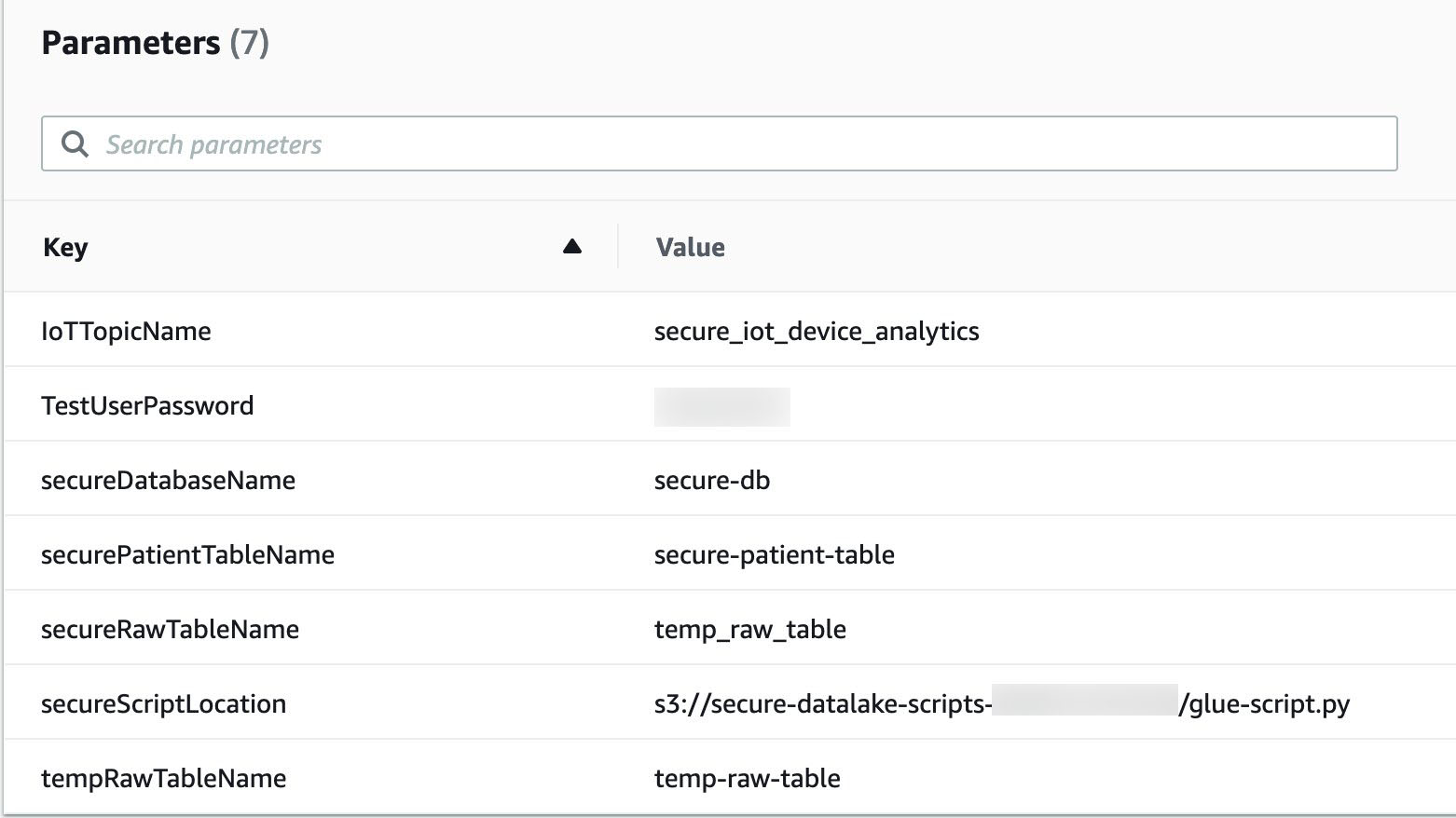
The following screenshot shows the key-values the stack created. We use the TestUserPassword parameter for the Lake Formation personas to sign in to the AWS Management Console.

Load the simulation data

Sign in to the AWS CloudShell console and wait for the terminal to start.

Stage the send-messages.sh script by running the Amazon S3 copy command:

aws s3 cp s3://secure-datalake-scripts-<ACCOUNT_ID>/send-messages.sh

Run your script by using the following command:

sh send-messages.sh.

The script runs for a few minutes and emits 300 messages. This sends MQTT messages to the secure_iot_device_analytics topic, filtered using IoT rules, processed using Kinesis Data Firehose, and converted to Parquet format. After a minute, data starts showing up in the raw bucket.

Run the AWS Glue ETL pipeline

Run AWS Glue workflow (secureGlueWorkflow) from the AWS Glue console; you can also schedule to run this using CloudWatch. It takes approximately 10 minutes to complete.

The AWS Glue job that is triggered as part of the workflow (ProcessSecureData) joins the patient metadata and patient metrics data. See the following code:

# Join Patient metadata and patient metrics dataframe
combined_df=Join.apply(patient_metadata, patient_metrics, 'PatientId', 'pid', transformation_ctx = "combined_df")

The ensuing dataframe contains sensitive information like FirstName, LastName, DOB, Address1, Address2, and AboutYourself. AboutYourself is freeform text entered by the patient during registration. In the following code snippet, the detect_sensitive_info function calls the Amazon Comprehend API to identify personally identifiable information (PII):

# Apply groupBy to get unique  AboutYourself records
group=combined_df.toDF().groupBy("pid","DOB", "FirstName", "LastName", "Address1", "Address2", "AboutYourself").count()
# Apply detect_sensitive_info to get the redacted string after masking  PII data
df_with_about_yourself = Map.apply(frame = group_df, f = detect_sensitive_info)
# Apply encryption to the identified fields
df_with_about_yourself_encrypted = Map.apply(frame = group_df, f = encrypt_rows)

Amazon Comprehend returns an object that has information about the entity name and entity type. Based on your needs, you can filter the entity types that need to be masked.

These fields are masked, encrypted, and written to their respective S3 buckets where fine-grained access controls are applied via Lake Formation:

  • Masked datas3://secure-data-lake-masked-<ACCOUNT_ID>
    secure-dl-masked-data/
  • Encrypted datas3://secure-data-lake-masked-<ACCOUNT_ID>
    secure-dl-encrypted-data/
  • Curated datas3://secure-data-lake-<ACCOUNT_ID>
    secure-dl-curated-data/

Now that the tables have been defined, we review permissions using Lake Formation.

Enable Lake Formation fine-grained access

To enable fine-grained access, we first add a Lake Formation admin user.

  1. On the Lake Formation console, select Add other AWS users or roles.
  2. On the drop-down menu, choose secure-lf-admin.
  3. Choose Get started.
  4. In the navigation pane, choose Settings.
  5. On the Data Catalog Settings page, deselect Use only IAM access control for new databases and Use only IAM access control for new tables in new databases.
  6. Choose Save.

Grant access to different personas

Before we grant permissions to different user personas, let’s register the S3 locations in Lake Formation so these personas can access S3 data without granting access through AWS Identity and Access Management (IAM).

  1. On the Lake Formation console, choose Register and ingest in the navigation pane.
  2. Choose Data lake locations.
  3. Choose Register location.
  4. Find and select each of the following S3 buckets and choose Register location:
    1. s3://secure-raw-bucket-<ACCOUNT_ID>/temp-raw-table
    2. s3://secure-data-lake-masked-<ACCOUNT_ID>/secure-dl-encrypted-data
    3. s3://secure-data-lake-<ACCOUNT_ID>/secure-dl-curated-data
    4. s3://secure-data-lake-masked-<ACCOUNT_ID>/secure-dl-masked-data

We’re now ready to grant access to our different users.

Grant read-only access to all the tables to secure-lf-admin

First, we grant read-only access to all the tables for the user secure-lf-admin.

  1. Sign in to the console with secure-lf-admin (use the password value for TestUserPassword from the CloudFormation stack) and make sure you’re in the same Region.
  2. Navigate to AWS Lake Formation console
  3. Under Data Catalog, choose Databases.
  4. Select the database secure-db.
  5. On the Actions drop-down menu, choose Grant.
  6. Select IAM users and roles.
  7. Choose the role secure-lf-admin.
  8. Under Policy tags or catalog resources, select Named data catalog resources.
  9. For Database, choose the database secure-db.
  10. For Tables, choose All tables.
  11. Under Permissions, select Table permissions.
  12. For Table permissions, select Super.
  13. Choose Grant.
  14. Choosesecure_dl_curated_data table.
  15. On the Actions drop-down menu, chose View permissions.
  16. Check IAMAllowedPrincipals and select Revoke and click on Revoke button.

You can confirm your user permissions on the Data Permissions page.

Grant read-only access to secure-lf-business-analyst

Now we grant read-only access to certain encrypted columns to the user secure-lf-business-analyst.

  1. On the Lake Formation console, under Data Catalog, choose Databases.
  2. Select the database secure-db and choose View tables.
  3. Select the table secure_dl_encrypted_data.
  4. On the Actions drop-down menu, choose Grant.
  5. Select IAM users and roles.
  6. Choose the role secure-lf-business-analyst.
  7. Under Permissions, select Column-based permissions.
  8. Choose the following columns:
    1. count
    2. address1_encrypted
    3. firstname_encrypted
    4. address2_encrypted
    5. dob_encrypted
    6. lastname_encrypted
  9. For Grantable permissions, select Select.
  10. Choose Grant.
  11. Chose secure_dl_encrypted_data table.
  12. On the Actions drop-down menu, chose View permissions.
  13. Check IAMAllowedPrincipals and select Revoke and click on Revoke button.

You can confirm your user permissions on the Data Permissions page.

Grant read-only access to secure-lf-data-scientist

Lastly, we grant read-only access to masked data to the user secure-lf-data-scientist.

  1. On the Lake Formation console, under Data Catalog, choose Databases.
  2. Select the database secure-db and choose View tables.
  3. Select the table secure_dl_masked_data.
  4. On the Actions drop-down menu, choose Grant.
  5. Select IAM users and roles.
  6. Choose the role secure-lf-data-scientist.
  7. Under Permissions, select Table permissions.
  8. For Table permissions, select Select.
  9. Choose Grant.
  10. Under Data Catalog, chose Tables.
  11. Chose secure_dl_masked_data table.
  12. On the Actions drop-down menu, chose View permissions.
  13. Check IAMAllowedPrincipals and select Revoke and click on Revoke button.

You can confirm your user permissions on the Data Permissions page.

Query the data lake using Athena from different personas

To validate the permissions of different personas, we use Athena to query against the S3 data lake.

Make sure you set the query result location to the location created as part of the CloudFormation stack (secure-athena-query-<ACCOUNT_ID>). The following screenshot shows the location information in the Settings section on the Athena console.

You can see all the tables listed under secure-db.

  1. Sign in to the console with secure-lf-admin (use the password value for TestUserPassword from the CloudFormation stack) and make sure you’re in the same Region.
  2. Navigate to Athena Console.
  3. Run a SELECT query against the secure_dl_curated_data

The user secure-lf-admin should see all the columns with encryption or masking.

Now let’s validate the permissions of secure-lf-business-analyst user.

  1. Sign in to the console with secure-lf-business-analyst.
  2. Navigate to Athena console.
  3. Run a SELECT query against the secure_dl_encrypted_data table.

The secure-lf-business-analyst user can only view the selected encrypted columns.

Lastly, let’s validate the permissions of secure-lf-data-scientist.

  1. Sign in to the console with secure-lf-data-scientist.
  2. Run a SELECT query against the secure_dl_masked_data table.

The secure-lf-data-scientist user can only view the selected masked columns.

If you try to run a query on different tables, such as secure_dl_curated_data, you get an error message for insufficient permissions.

Clean up

To avoid unexpected future charges, delete the CloudFormation stack.

Conclusion

In this post, we presented a potential solution for processing and storing sensitive data workloads in an S3 data lake. We demonstrated how to build a data lake on AWS to ingest, transform, aggregate, and analyze data from IoT devices in near-real time. This solution also demonstrates how you can mask and encrypt sensitive data, and use fine-grained column-level security controls with Lake Formation, which benefits those with a higher level of security needs.

Lake Formation recently announced the preview for row-level access; and you can sign up for the preview now!


About the Authors

Shekar Tippur is an AWS Partner Solutions Architect. He specializes in machine learning and analytics workloads. He has been helping partners and customers adopt best practices and discover insights from data.


Ramakant Joshi is an AWS Solution Architect, specializing in the analytics and serverless domain. He has over 20 years of software development and architecture experience, and is passionate about helping customers in their cloud journey.


Navnit Shukla is AWS Specialist Solution Architect, Analytics, and is passionate about helping customers uncover insights from their data. He has been building solutions to help organizations make data-driven decisions.

ERGO Breaks New Frontiers for Insurance with AI Factory on AWS

Post Syndicated from Piotr Klesta original https://aws.amazon.com/blogs/architecture/ergo-breaks-new-frontiers-for-insurance-with-ai-factory-on-aws/

This post is co-authored with Piotr Klesta, Robert Meisner and Lukasz Luszczynski of ERGO

Artificial intelligence (AI) and related technologies are already finding applications in our homes, cars, industries, and offices. The insurance business is no exception to this. When AI is implemented correctly, it adds a major competitive advantage. It enhances the decision-making process, improves efficiency in operations, and provides hassle-free customer assistance.

At ERGO Group, we realized early on that innovation using AI required more flexibility in data integration than most of our legacy data architectures allowed. Our internal governance, data privacy processes, and IT security requirements posed additional challenges towards integration. We had to resolve these issues in order to use AI at the enterprise level, and allow for sensitive data to be used in a cloud environment.

We aimed for a central system that introduces ‘intelligence’ into other core application systems, and thus into ERGO’s business processes. This platform would support the process of development, training, and testing of complex AI models, in addition to creating more operational efficiency. The goal of the platform is to take the undifferentiated heavy lifting away from our data teams so that they focus on what they do best – harness data insights.

Building ERGO AI Factory to power AI use cases

Our quest for this central system led to the creation of AI Factory built on AWS Cloud. ERGO AI Factory is a compliant platform for running production-ready AI use cases. It also provides a flexible model development and testing environment. Let’s look at some of the capabilities and services we offer to our advanced analytics teams.

Figure 1: AI Factory imperatives

Figure 1: AI Factory imperatives

  • Compliance: Enforcing security measures (for example, authentication, encryption, and least privilege) was one of our top priorities for the platform. We worked closely with the security teams to meet strict domain and geo-specific compliance requirements.
  • Data governance: Data lineage and deep metadata extraction are important because they support proper data governance and auditability. They also allow our users to navigate a complex data landscape. Our data ingestion frameworks include a mixture of third party and AWS services to capture and catalog both technical and business metadata.
  • Data storage and access: AI Factory stores data in Amazon Simple Storage Service (S3) in a secure and compliant manner. Access rights are only granted to individuals working on the corresponding projects. Roles are defined in Active Directory.
  • Automated data pipelines: We sought to provide a flexible and robust data integration solution. An ETL pipeline using Apache Spark, Apache Airflow, and Kubernetes pods is central to our data ingestion. We use this for AI model development and subsequent data preparation for operationalization and model integration.
  • Monitoring and security: AI Factory relies on open-source cloud monitoring solutions like Grafana to detect security threats and anomalies. It does this by collecting service and application logs, tracking metrics, and generating alarms.
  • Feedback loop: We store model inputs/outputs and use BI tools, such as Amazon QuickSight, to track the behavior and performance of productive AI models. It’s important to share such information with our business partners so we can build their trust and confidence with AI.
  • Developer-friendly environment: Creating AI models is possible in a notebook-style or integrated development environment. Because our data teams use a variety of machine learning (ML) frameworks and libraries, we keep our platform extensible and our framework agnostic. We support Python/R, Apache Spark, PyTorch and TensorFlow, and more. All this is bolstered by CI/CD processes that accelerate delivery and reduce errors.
  • Business process integration: AI Factory offers services to integrate ML models into existing business processes. We focus on standardizing processes and close collaboration with business and technical stakeholders. Our overarching goal is to operationalize the AI model in the shortest possible timeframe, while preserving high quality and security standards.

AI Factory architecture

So far, we have looked at the functional building blocks of the AI Factory. Let’s take an architectural view of the platform using a five-step workflow:

Figure 2: AI Factory high-level architecture

Figure 2: AI Factory high-level architecture

  1. Data ingestion environment: We use this environment to ingest data from the prominent on-premises ERGO data sources. We can schedule the batch or Delta transfer data to various cloud destinations using multiple Kubernetes-hosted microservices. Once ingested, data is persisted and cataloged as ERGO’s data lake on Amazon S3. It is prepared for processing by the upstream environments.
  2. Model development environment: This environment is used primarily by data scientists and data engineers. We use Amazon EMR and Amazon SageMaker extensively for data preparation, data wrangling, experimentation with predictive models, and development through rapid iterations.
  3. Model operationalization environment: Trained models with satisfactory KPIs are promoted from the model development to the operationalization environment. This is where we integrate AI models in business processes. The team focuses on launching and optimizing the operation of services and algorithms.
    • Integration with ERGO business processes is achieved using Kubernetes-hosted ‘Model Service.’ This allows us to infuse AI models provided by data scientists in existing business processes.
    • An essential part of model operationalization is to continuously monitor the quality of the deployed ML models using the ‘feedback loop service.’
  4. Model insights environment: This environment is used for displaying information about platform performance, processes, and analytical data. Data scientists use its services to check for unexpected bias or performance drifts that the model could exhibit. Feedback coming from the business through the “feedback loop service’ allows them to identify problems fast and retrain the model.
  5. Shared services: Though shown as the fifth step of the workflow, the shared services environment supports almost every step in the process. It provides common, shared components between different parts of the platform managing CI/CD and orchestration processes within the AI factory. Additional services like platform logging and monitoring, authentication, and metadata management are also delivered from the shared services environment.

A binding theme across the various subplatforms is that all provisioning and deployment activities are automated using Infrastructure as Code (IaC) practices. This reduces the potential for human error, provides architectural flexibility, and greatly speeds up software development and our infrastructure-related operations.

All components of the AI factory are run in the AWS Cloud and can be scaled and adapted as needed. The connection between model development and operationalization happens at well-defined interfaces to prevent unnecessary coupling of components.

Lessons learned

Security first

  • Align with security early and often
  • Understand all the regulatory obligations and document them as critical, non-functional requirements

Modular approach

  • Combine modern data science technology and professional IT with a cross-functional, agile way of working
  • Apply loosely coupled services with an API-first approach

Data governance

  • Tracking technical metadata is important but not sufficient, you need business attributes too
  • Determine data ownership in operational systems to map upstream data governance workflows
  • Establish solutions to data masking as the data moves across sub-platforms
  • Define access rights and permissions boundaries among various personas

FinOps strategy

  • Carefully track platform cost
  • Assign owners responsible for monitoring and cost improvements
  • Provide regular feedback to platform stakeholders on usage patterns and associated expenses

Working with our AWS team

  • Establish cadence for architecture review and new feature updates
  • Plan cloud training and enablement

The future for the AI factory

The creation of the AI Factory was an essential building block of ERGO’s strategy. Now we are ready to embrace the next chapter in our advanced analytics journey.

We plan to focus on important use cases that will deliver the highest business value. We want to make the AI Factory available to ERGO’s international subsidiaries. We are also enhancing and scaling its capabilities. We are creating an ‘analytical content hub’ based on automated text extraction, improving speech to text, and developing translation processes for all unstructured and semistructured data using AWS AI services.

Translating content dynamically by using Amazon S3 Object Lambda

Post Syndicated from James Beswick original https://aws.amazon.com/blogs/compute/translating-content-dynamically-by-using-amazon-s3-object-lambda/

This post is written by Sandeep Mohanty, Senior Solutions Architect.

The recent launch of Amazon S3 Object Lambda creates many possibilities to transform data in S3 buckets dynamically. S3 Object Lambda can be used with other AWS serverless services to transform content stored in S3 in many creative ways. One example is using S3 Object Lambda with Amazon Translate to translate and serve content from S3 buckets on demand.

Amazon Translate is a serverless machine translation service that delivers fast and customizable language translation. With Amazon Translate, you can localize content such as websites and applications to serve a diverse set of users.

Using S3 Object Lambda with Amazon Translate, you do not need to translate content in advance for all possible permutations of source to target languages. Instead, you can transform content in near-real time using a data driven model. This can serve multiple language-specific applications simultaneously.

S3 Object Lambda enables you to process and transform data using Lambda functions as objects are being retrieved from S3 by a client application. S3 GET object requests invoke the Lambda function and you can customize it to transform the content to meet specific requirements.

For example, if you run a website or mobile application with global visitors, you must provide translations in multiple languages. Artifacts such as forms, disclaimers, or product descriptions can be translated to serve a diverse global audience using this approach.

Solution architecture

This is the high-level architecture diagram for the example application that translates dynamic content on demand:

Solution architecture

In this example, you create an S3 Object Lambda that intercepts S3 GET requests for an object. It then translates the file to a target language, passed as an argument appended to the S3 object key. At a high level, the steps can be summarized as follows:

  1. Create a Lambda function to translate data from a source language to a target language using Amazon Translate.
  2. Create an S3 Object Lambda Access Point from the S3 console.
  3. Select the Lambda function created in step 1.
  4. Provide a supporting S3 Access Point to give S3 Object Lambda access to the original object.
  5. Retrieve a file from S3 by invoking the S3 GetObject API, and pass the Object Lambda Access Point ARN as the bucket name instead of the actual S3 bucket name.

Creating the Lambda function

In the first step, you create the Lambda function, DynamicFileTranslation. This Lambda function is invoked by an S3 GET Object API call and it translates the requested object. The target language is passed as an argument appended to the S3 object key, corresponding to the object being retrieved.

For example, for the object key passed in the S3 GetObject API call is customized to look something like “ContactUs/contact-us.txt#fr”, the characters after the pound sign represent the code for the target language. In this case, ‘fr’ is French. The full list of supported languages and language codes can be found here.

This Lambda function dynamically translates the content of an object in S3 to a target language:

import json
import boto3
from urllib.parse import urlparse, unquote
from pathlib import Path
def lambda_handler(event, context):
    print(event)

   # Extract the outputRoute and outputToken from the object context
    object_context = event["getObjectContext"]
    request_route = object_context["outputRoute"]
    request_token = object_context["outputToken"]

   # Extract the user requested URL and the supporting access point arn
    user_request_url = event["userRequest"]["url"]
    supporting_access_point_arn = event["configuration"]["supportingAccessPointArn"]

    print("USER REQUEST URL: ", user_request_url)
   
   # The S3 object key is after the Host name in the user request URL.
   # The user request URL looks something like this, 
   # https://<User Request Host>/ContactUs/contact-us.txt#fr.
   # The target language code in the S3 GET request is after the "#"
    
    user_request_url = unquote(user_request_url)
    result = user_request_url.split("#")
    user_request_url = result[0]
    targetLang = result[1]
    
   # Extract the S3 Object Key from the user requested URL
    s3Key = str(Path(urlparse(user_request_url).path).relative_to('/'))
       
   # Get the original object from S3
    s3 = boto3.resource('s3')
    
   # To get the original object from S3,use the supporting_access_point_arn 
    s3Obj = s3.Object(supporting_access_point_arn, s3Key).get()
    srcText = s3Obj['Body'].read()
    srcText = srcText.decode('utf-8')

   # Translate original text
    translateClient = boto3.client('translate')
    response = translateClient.translate_text(
                                                Text = srcText,
                                                SourceLanguageCode='en',
                                                TargetLanguageCode=targetLang)
    
  # Write object back to S3 Object Lambda
    s3client = boto3.client('s3')
    s3client.write_get_object_response(
                                        Body=response['TranslatedText'],
                                        RequestRoute=request_route,
                                        RequestToken=request_token )
    
    return { 'statusCode': 200 }

The code in the Lambda function:

  • Extracts the outputRoute and outputToken from the object context. This defines where the WriteGetObjectResponse request is delivered.
  • Extracts the user-requested url from the event object.
  • Parses the S3 object key and the target language that is appended to the S3 object key.
  • Calls S3 GetObject to fetch the raw text of the source object.
  • Invokes Amazon Translate with the raw text extracted.
  • Puts the translated output back to S3 using the WriteGetObjectResponse API.

Configuring the Lambda IAM role

The Lambda function needs permissions to call back to the S3 Object Lambda access point with the WriteGetObjectResponse. It also needs permissions to call S3 GetObject and Amazon Translate. Add the following permissions to the Lambda execution role:

{
    "Version": "2012-10-17",
    "Statement": [
        {
            "Sid": "S3ObjectLambdaAccess",
            "Effect": "Allow",
            "Action": [
                "s3:GetObject",
                "s3-object-lambda:WriteGetObjectResponse"
            ],
            "Resource": [
                "<arn of your S3 access point/*>”,
                "<arn of your Object Lambda accesspoint>"
            ]
        },
        {
            "Sid": "AmazonTranslateAccess",
            "Effect": "Allow",
            "Action": "translate:TranslateText",
            "Resource": "*"
        }
    ]
}

Deploying the Lambda using an AWS SAM template

Alternatively, deploy the Lambda function with the IAM role by using an AWS SAM template. The code for the Lambda function and the AWS SAM template is available for download from GitHub.

Creating the S3 Access Point

  1. Navigate to the S3 console and create a bucket with a unique name.
  2. In the S3 console, select “Access Points” and choose “Create access point”. Enter a name for the access point.
  3. For Bucket name, enter the S3 bucket name you entered in step 1.Create access point

This access point is the supporting access point for the Object Lambda Access Point you create in the next step. Keep all other settings on this page as default.

After creating the S3 access point, create the S3 Object Lambda Access Point using the supporting Access Point. The Lambda function you created earlier uses the supporting Access Point to download the original untransformed objects from S3.

Create Object Lambda Access Point

In the S3 console, go to the Object Lambda Access Point configuration and create an Object Lambda Access Point. Enter a name.

Create Object Lambda Access Point

For the Lambda function configurations, associate this with the Lambda function created earlier. Select the latest version of the Lambda function and keep all other settings as default.

Select Lambda function

To understand how to use the other settings of the S3 Object Lambda configuration, refer to the product documentation.

Testing dynamic content translation

In this section, you create a Python script and invoke the S3 GetObject API twice. First, against the S3 bucket and then against the Object Lambda Access Point. You can then compare the output to see how content is transformed using Object Lambda:

  1. Upload a text file to the S3 bucket using the Object Lambda Access Point you configured. For example, upload a sample “Contact Us” file in English to S3.
  2. To use the object Lambda Access Point, locate its ARN from the Properties tab of the Object Lambda Access Point.Object Lambda Access Point
  3. Create a local file called s3ol_client.py that contains the following Python script:
    import json
    import boto3
    import sys, getopt
      
    def main(argv):
    	
      try:	
        targetLang = sys.argv[1]
        print("TargetLang = ", targetLang)
        
        s3 = boto3.client('s3')
        s3Bucket = "my-s3ol-bucket"
        s3Key = "ContactUs/contact-us.txt"
    
        # Call get_object using the S3 bucket name
        response = s3.get_object(Bucket=s3Bucket,Key=s3Key)
        print("Original Content......\n")
        print(response['Body'].read().decode('utf-8'))
    
        print("\n")
    
        # Call get_object using the S3 Object Lambda access point ARN
        s3Bucket = "arn:aws:s3-object-lambda:us-west-2:123456789012:accesspoint/my-s3ol-access-point"
        s3Key = "ContactUs/contact-us.txt#" + targetLang
        response = s3.get_object(Bucket=s3Bucket,Key=s3Key)
        print("Transformed Content......\n")
        print(response['Body'].read().decode('utf-8'))
    
        return {'Success':200}             
      except:
        print("\n\nUsage: s3ol_client.py <Target Language Code>")
    
    #********** Program Entry Point ***********
    if __name__ == '__main__':
        main(sys.argv[1: ])
    
  4. Run the client program from the command line, passing the target language code as an argument. The full list of supported languages and codes in Amazon Translate can be found here.python s3ol_client.py "fr"

The output looks like this:

Example output

The first output is the original content that was retrieved when calling GetObject with the S3 bucket name. The second output is the transformed content when calling GetObject against the Object Lambda access point. The content is transformed by the Lambda function as it is being retrieved, and translated to French in near-real time.

Conclusion

This blog post shows how you can use S3 Object Lambda with Amazon Translate to simplify dynamic content translation by using a data driven approach. With user-provided data as arguments, you can dynamically transform content in S3 and generate a new object.

It is not necessary to create a copy of this new object in S3 before returning it to the client. We also saw that it is not necessary for the object with the same name to exist in the S3 bucket when using S3 Object Lambda. This pattern can be used to address several real world use cases that can benefit from the ability to transform and generate S3 objects on the fly.

For more serverless learning resources, visit Serverless Land.

Vertical Integration Strategy Powered by Amazon EventBridge

Post Syndicated from Tiago Oliveira original https://aws.amazon.com/blogs/architecture/vertical-integration-strategy-powered-by-amazon-eventbridge/

Over the past few years, midsize and large enterprises have adopted vertical integration as part of their strategy to optimize operations and profitability. Vertical integration consists of separating different stages of the production line from other related departments, such as marketing and logistics. Enterprises implement such strategy to gain full control of their value chain: from the raw material production to the assembly lines and end consumer.

To achieve operational efficiency, enterprises must keep a level of independence between departments. However, this can lead to unstandardized operations and communication issues. Moreover, with this kind of autonomy for independent and dynamic verticals, the enterprise may lose some measure of visibility and control. As a result, it becomes challenging to generate a basic report from multiple departments. This blog post provides a high-level solution to integrate your different business verticals, using an event-driven architecture on top of Amazon EventBridge.

Event-driven architecture

Event-driven architecture is an architectural pattern to model communication between services while decoupling applications from each other. Applications scale and fail independently, and a central event bus facilitates the communication between the services in the enterprise. Instead of a particular application sending a request directly to another, it produces an event. The central event router captures it and forwards the message to the proper destinations.

For instance, when a customer places a new order on the retail website, the application sends the event to the event bus. Following, the event bus sends the message to the ERP system and the fulfillment center for dispatch. In this scenario, we call the application sending the event, an event publisher, and the applications receiving the event, event consumers.

Because all messages are going through the central event bus, there is clear independence between the applications within the enterprise. Here are some benefits:

  • Application independence occurs even if they belong to the same business workflow
  • You can plug in more event consumers to receive the same event type
  • You can add a data lake to receive all new order events from the retail website
  • You can receive all the events from the payment system and the customer relations department

This ensures you can integrate independent departments, increase overall visibility, and make sense of specific processes happening in the organization using the right tools.

Implementing event-driven architecture with Amazon EventBridge

Each vertical organically generates lifecycle events. Enterprises can use the event-driven architecture paradigm to make the information flow between the departments by asynchronously exchanging events through the event bus. This way, each department can react to events generated by other departments and initiate processes or actions depending on its business needs.

Such an approach creates a dynamic and flexible choreography between the different participants, which is unique to the enterprise. Such choreography can be followed and monitored using analytics and fine-grained event data collected on the data lake. Read Using AWS X-Ray tracing with Amazon EventBridge to learn how to debug and analyze this kind of distributed application.

Figure 1. Architecture diagram depicting enterprise vertical integration with Amazon EventBridge

Figure 1. Architecture diagram depicting enterprise vertical integration with Amazon EventBridge

In Figure 1, Amazon EventBridge works as the central event bus, the core component of this event-driven architecture. Through Amazon EventBridge, each event publisher sends or receives lifecycle events to and from all the other participants. Amazon EventBridge has an advanced routing mechanism using the concept of rules. Each rule defines up to five targets for the event arriving on the bus. Events are selected based on the event pattern. You can set up routing rules to determine where to send your data to build application architectures. These will react in real time to your data sources, with event publisher and consumer decoupled.

In addition to initiating the heavy routing and distribution of events, Amazon EventBridge can also give real-time insights into how the business runs. Using metrics automatically sent to Amazon CloudWatch, it is possible to see which kinds of events are arriving, and at which rate. You can also see how those events are distributed across the registered targets, and any failures that occur during this distribution. Every event can also be archived using the Amazon EventBridge events archiving feature.

Amazon Simple Storage Service (S3) is the backend storage, or data lake, for all the events that have ever transited via the event bus. With Amazon S3, customers have a cost-efficient storage service at any scale, with 11 9’s of durability. To help customers manage and secure their data, S3 provides features such as Amazon S3 Lifecycle to optimize costs. S3 Object Lock allows the write-once-read-many (WORM) model. You can expand this data and transform it into information using S3. Using services like Amazon AthenaAmazon Redshift, and Amazon EMR, those events can be transformed, correlated, and aggregated to generate insights on the business. The Amazon S3 data lake can also be the input to a data warehouse, machine learning models, and real-time analytics. Learn more about how to use Amazon S3 as the data lake storage.

A critical feature of this solution is the initiation of complex queries on top of the data lake. Amazon API Gateway provides one single flexible and elastic API entry point to retrieve data from the data lake. It also can publish events directly to the event bus. For complex queries, Amazon API Gateway can be integrated with an AWS Lambda. It will coordinate the execution of standard SQL queries using Amazon Athena as the query engine. You can read about a fully functional example of such an API called athena-express.

After collecting data from multiple departments, third-party entities, and shop floors, you can use the data to derive business value using cross-organization dashboards. In this way, you can increase visibility over the different entities and make sense of the data from the distributed systems. Even though this design allows you to use your favorite BI tool, we are using Amazon QuickSight for this solution. For example, with QuickSight, you can author your interactive dashboards, which include machine learning-powered insights. Those dashboards can then connect the marketing campaigns data with the sales data. You can measure how effective those campaigns were and forecast the demand on the production lines.

Conclusion

In this blog post, we showed you how to use Amazon EventBridge as an event bus to allow event-driven architectures. This architecture pattern streamlines the adoption of vertical integration. Enterprises can decouple IT systems from each other while retaining visibility into the data they generate. Integrating those systems can happen asynchronously using a choreography approach instead of having an orchestrator as a central component. There are technical challenges to implement this kind of solution, such as maintaining consistency in distributed applications and transactions spanning multiple microservices. Refer to the saga pattern for microservices-based architecture, and how to implement it using AWS Step Functions.

With a data lake in place to collect all the data produced by IT systems, you can create BI dashboards that provide a holistic view of multiple departments. Moreover, it allows organizations to get better insights into their valuable data and explore other use cases, such as machine learning. To support the data lake creation and management, refer to AWS Lake Formation and a series of other blog posts.

To learn more about Amazon EventBridge from a hands-on perspective, refer to this EventBridge workshop.

Building well-architected serverless applications: Managing application security boundaries – part 2

Post Syndicated from Julian Wood original https://aws.amazon.com/blogs/compute/building-well-architected-serverless-applications-managing-application-security-boundaries-part-2/

This series uses the AWS Well-Architected Tool with the Serverless Lens to help customers build and operate applications using best practices. In each post, I address the nine serverless-specific questions identified by the Serverless Lens along with the recommended best practices. See the introduction post for a table of contents and explanation of the example application.

Security question SEC2: How do you manage your serverless application’s security boundaries?

This post continues part 1 of this security question. Previously, I cover how to evaluate and define resource policies, showing what policies are available for various serverless services. I show some of the features of AWS Web Application Firewall (AWS WAF) to protect APIs. Then then go through how to control network traffic at all layers. I explain how AWS Lambda functions connect to VPCs, and how to use private APIs and VPC endpoints. I walk through how to audit your traffic.

Required practice: Use temporary credentials between resources and components

Do not share credentials and permissions policies between resources to maintain a granular segregation of permissions and improve the security posture. Use temporary credentials that are frequently rotated and that have policies tailored to the access the resource needs.

Use dynamic authentication when accessing components and managed services

AWS Identity and Access Management (IAM) roles allows your applications to access AWS services securely without requiring you to manage or hardcode the security credentials. When you use a role, you don’t have to distribute long-term credentials such as a user name and password, or access keys. Instead, the role supplies temporary permissions that applications can use when they make calls to other AWS resources. When you create a Lambda function, for example, you specify an IAM role to associate with the function. The function can then use the role-supplied temporary credentials to sign API requests.

Use IAM for authorizing access to AWS managed services such as Lambda or Amazon S3. Lambda also assumes IAM roles, exposing and rotating temporary credentials to your functions. This enables your application code to access AWS services.

Use IAM to authorize access to internal or private Amazon API Gateway API consumers. See this list of AWS services that work with IAM.

Within the serverless airline example used in this series, the loyalty service uses a Lambda function to fetch loyalty points and next tier progress. AWS AppSync acts as the client using an HTTP resolver, via an API Gateway REST API /loyalty/{customerId}/get resource, to invoke the function.

To ensure only AWS AppSync is authorized to invoke the API, IAM authorization is set within the API Gateway method request.

Viewing API Gateway IAM authorization

Viewing API Gateway IAM authorization

The IAM role specifies that appsync.amazonaws.com can perform an execute-api:Invoke on the specific API Gateway resource arn:aws:execute-api:${AWS::Region}:${AWS::AccountId}:${LoyaltyApi}/*/*/*

For more information, see “Using an IAM role to grant permissions to applications”.

Use a framework such as the AWS Serverless Application Model (AWS SAM) to deploy your applications. This ensures that AWS resources are provisioned with unique per resource IAM roles. For example, AWS SAM automatically creates unique IAM roles for every Lambda function you create.

Best practice: Design smaller, single purpose functions

Creating smaller, single purpose functions enables you to keep your permissions aligned to least privileged access. This reduces the risk of compromise since the function does not require access to more than it needs.

Create single purpose functions with their own IAM role

Single purpose Lambda functions allow you to create IAM roles that are specific to your access requirements. For example, a large multipurpose function might need access to multiple AWS resources such as Amazon DynamoDB, Amazon S3, and Amazon Simple Queue Service (SQS). Single purpose functions would not need access to all of them at the same time.

With smaller, single purpose functions, it’s often easier to identify the specific resources and access requirements, and grant only those permissions. Additionally, new features are usually implemented by new functions in this architectural design. You can specifically grant permissions in new IAM roles for these functions.

Avoid sharing IAM roles with multiple cloud resources. As permissions are added to the role, these are shared across all resources using this role. For example, use one dedicated IAM role per Lambda function. This allows you to control permissions more intentionally. Even if some functions have the same policy initially, always separate the IAM roles to ensure least privilege policies.

Use least privilege access policies with your users and roles

When you create IAM policies, follow the standard security advice of granting least privilege, or granting only the permissions required to perform a task. Determine what users (and roles) must do and then craft policies that allow them to perform only those tasks.

Start with a minimum set of permissions and grant additional permissions as necessary. Doing so is more secure than starting with permissions that are too lenient and then trying to tighten them later. In the unlikely event of misused credentials, credentials will only be able to perform limited interactions.

To control access to AWS resources, AWS SAM uses the same mechanisms as AWS CloudFormation. For more information, see “Controlling access with AWS Identity and Access Management” in the AWS CloudFormation User Guide.

For a Lambda function, AWS SAM scopes the permissions of your Lambda functions to the resources that are used by your application. You add IAM policies as part of the AWS SAM template. The policies property can be the name of AWS managed policies, inline IAM policy documents, or AWS SAM policy templates.

For example, the serverless airline has a ConfirmBooking Lambda function that has UpdateItem permissions to the specific DynamoDB BookingTable resource.

Parameters:
    BookingTable:
        Type: AWS::SSM::Parameter::Value<String>
        Description: Parameter Name for Booking Table
Resources:
    ConfirmBooking:
        Type: AWS::Serverless::Function
        Properties:
            FunctionName: !Sub ServerlessAirline-ConfirmBooking-${Stage}
            Policies:
                - Version: "2012-10-17"
                  Statement:
                      Action: dynamodb:UpdateItem
                      Effect: Allow
                      Resource: !Sub "arn:${AWS::Partition}:dynamodb:${AWS::Region}:${AWS::AccountId}:table/${BookingTable}"

One of the fastest ways to scope permissions appropriately is to use AWS SAM policy templates. You can reference these templates directly in the AWS SAM template for your application, providing custom parameters as required.

The serverless patterns collection allows you to build integrations quickly using AWS SAM and AWS Cloud Development Kit (AWS CDK) templates.

The booking service uses the SNSPublishMessagePolicy. This policy gives permission to the NotifyBooking Lambda function to publish a message to an Amazon Simple Notification Service (Amazon SNS) topic.

    BookingTopic:
        Type: AWS::SNS::Topic

    NotifyBooking:
        Type: AWS::Serverless::Function
        Properties:
            Policies:
                - SNSPublishMessagePolicy:
                      TopicName: !Sub ${BookingTopic.TopicName}
        …

Auditing permissions and removing unnecessary permissions

Audit permissions regularly to help you identify unused permissions so that you can remove them. You can use last accessed information to refine your policies and allow access to only the services and actions that your entities use. Use the IAM console to view when last an IAM role was used.

IAM last used

IAM last used

Use IAM access advisor to review when was the last time an AWS service was used from a specific IAM user or role. You can view last accessed information for IAM on the Access Advisor tab in the IAM console. Using this information, you can remove IAM policies and access from your IAM roles.

IAM access advisor

IAM access advisor

When creating and editing policies, you can validate them using IAM Access Analyzer, which provides over 100 policy checks. It generates security warnings when a statement in your policy allows access AWS considers overly permissive. Use the security warning’s actionable recommendations to help grant least privilege. To learn more about policy checks provided by IAM Access Analyzer, see “IAM Access Analyzer policy validation”.

With AWS CloudTrail, you can use CloudTrail event history to review individual actions your IAM role has performed in the past. Using this information, you can detect which permissions were actively used, and decide to remove permissions.

AWS CloudTrail

AWS CloudTrail

To work out which permissions you may need, you can generate IAM policies based on access activity. You configure an IAM role with broad permissions while the application is in development. Access Analyzer reviews your CloudTrail logs. It generates a policy template that contains the permissions that the role used in your specified date range. Use the template to create a policy that grants only the permissions needed to support your specific use case. For more information, see “Generate policies based on access activity”.

IAM Access Analyzer

IAM Access Analyzer

Conclusion

Managing your serverless application’s security boundaries ensures isolation for, within, and between components. In this post, I continue from part 1, looking at using temporary credentials between resources and components. I cover why smaller, single purpose functions are better from a security perspective, and how to audit permissions. I show how to use AWS SAM to create per-function IAM roles.

For more serverless learning resources, visit https://serverlessland.com.

Building a Showback Dashboard for Cost Visibility with Serverless Architectures

Post Syndicated from Peter Chung original https://aws.amazon.com/blogs/architecture/building-a-showback-dashboard-for-cost-visibility-with-serverless-architectures/

Enterprises with centralized IT organizations and multiple lines of businesses frequently use showback or chargeback mechanisms to hold their departments accountable for their technology usage and costs. Chargeback involves actually billing a department for the cost of their division’s usage. Showback focuses on visibility to make the department more cost conscientious and encourage operational efficiency.

Building a showback mechanism can be potentially challenging for business and financial analysts of an AWS Organization. You may not have the scripting or data engineering skills needed to coordinate workflows and build reports at scale. Although you can use AWS Cost Explorer as starting point, you may want greater customizability, larger datasets beyond a one-year period, and more of a business intelligence (BI) experience.

In this post, we discuss the benefits of building a showback dashboard using the AWS Cost and Usage Report (AWS CUR). You can track costs by cost center, business unit, or project using managed services. Using a showback strategy, you can consolidate and present costs to a business unit to show resource use over a set period of time for your entire AWS Organization. Building this solution with managed services allows you to spend time understanding your costs rather than maintaining the underlying infrastructure.

This solution highlights AWS Glue DataBrew to prepare your data into the appropriate format for dashboards. We recommend DataBrew because it provides a no-code environment for data transformation. It allows anyone to create dashboards similar to those built in the Cloud Intelligence Dashboards Workshop for your Organization.

Figure 1. QuickSight showback dashboard using CUR data transformed by Glue DataBrew and leveraging QuickSight insights

Figure 1. QuickSight showback dashboard using CUR data transformed by Glue DataBrew and leveraging QuickSight insights

Tags for cost allocation

The success of your showback dashboard partially depends on your cost allocation tagging strategy. Typically, customers use business tags such as cost center, business unit, or project to associate AWS costs with traditional financial reporting dimensions within their organization.

The CUR supports the ability to break down AWS costs by tag. For example, if a group of resources are labeled with the same tag, you’ll be able to see the total cost and usage of that group of resources. Read more about Tagging Best Practices to develop a tagging strategy for your organization.

A serverless data workflow for showback dashboards

You can build showback dashboards with managed services such as Amazon QuickSight, without the need to write any code or manage any servers.

Figure 2. A serverless architecture representing data workflow

Figure 2. A serverless architecture representing data workflow

AWS automatically delivers the data you need for showback dashboards through the CUR. Once this data arrives in an Amazon Simple Storage Service (S3) bucket, you can transform the data without the need to write any code by using DataBrew. You can also automatically identify the data schema, and catalog the data’s properties to run queries using Amazon Athena. Lastly, you can visualize the results by publishing and sharing dashboards to key stakeholders within your organization using Amazon QuickSight.

The key benefits of this approach are:

  • Automatic data delivery
  • No-code data transformation
  • Automatic cataloging and querying
  • Serverless data visualization

Let’s take a look at each in more detail.

Automatic data delivery

The CUR is the source for historical cost and usage data. The CUR provides the most comprehensive set of cost and usage data available and will include your defined cost allocation tags for your entire Organization. You configure CUR to deliver your billing data to an Amazon S3 bucket at the payer account level. This will consolidate data for all linked accounts. After delivery starts, Amazon updates the CUR files at least once a day.

No-code data transformation

You can use DataBrew to transform the data in the Amazon S3 bucket aggregating cost and usage according to your tagging strategy. DataBrew summarizes your data for discovery. You can also run transformations called “jobs” in DataBrew without writing any code, using over 250 built-in transforms. Figures 3 through 5 show several job examples.

Figure 3. DataBrew recipe action: rename column

Figure 3. DataBrew recipe action: rename column

Figure 4. DataBrew recipe action: Create column from function

Figure 4. DataBrew recipe action: Create column from function

Figure 5. DataBrew recipe action: fill missing values

Figure 5. DataBrew recipe action: fill missing values

For a full list of columns available in CUR, review the CUR Data Dictionary. Following is a list of relevant columns for an executive summary showback dashboard:

  • bill_billing_period_start_date
  • line_item_usage_account_id
  • line_item_line_item_type
  • product_product_name
  • product_product_family
  • product_product_transfer_type
  • savings_plan_savings_plan_effective cost
  • reservation_effective_cost
  • line_item_unblended_cost

Based on data refresh and business requirements, DataBrew can run a job on a recurring basis (for example, every 12 hours). This can be run at a particular time of day, or as defined by a valid CRON expression. This helps you automate your transformation workflows.

Automatic cataloging and querying

You can use a Glue crawler to automatically classify your data to determine the data’s format, schema, and associated properties. The crawlers write metadata to an AWS Glue Data Catalog to help data users find the data they need.

With the results in Amazon S3, and the metadata in the Glue Data Catalog, you can run standard SQL to queries with Athena. This will help you make more informed business decisions by tracking financial metrics and optimizing costs. This is done directly in Amazon S3 without having to move around data. Using standard SQL, you can create views that aggregate cost and usage by your defined tags.

Serverless data visualization

You can use Amazon QuickSight to create and share dashboards with your teams for cost visibility. QuickSight provides native integration with Athena and S3, and lets you easily create and publish interactive BI dashboards that include ML-powered insights. When building a showback dashboard such as the example in Figure 1, QuickSight authors create visuals and publish interactive dashboards.

Readers log in using your preferred authentication mechanism to view the shared dashboard. You can then filter data based on billing periods, account number, or cost allocation tags. You can also drill down to details using a web browser or mobile app.

Conclusion

In this blog, we’ve discussed designing and building a data transformation process and a showback dashboard. This gives you highly granular cost visualization without having to provision and manage any servers. You can use managed services such as AWS Glue DataBrew, Amazon Athena, and Amazon QuickSight to crawl, catalog, analyze, and visualize your data.

We recommend defining your organization tagging strategy to be able to view costs by tags. You can then get started by creating Cost and Usage Reports. With the data in Amazon S3, you can use the services described in this post to transform the data that works for your business. Additionally, you can get started today by experimenting with the Cloud Intelligence Dashboards Workshop. This workshop provides examples of visualizations that you can build using native AWS services on top of your Cost and Usage Report. You will be able to get cost, usage, and operational insights about your AWS Cloud usage.

Security is the top priority for Amazon S3

Post Syndicated from Maddie Bacon original https://aws.amazon.com/blogs/security/security-is-the-top-priority-for-amazon-s3/

Amazon Simple Storage Service (Amazon S3) launched 15 years ago in March 2006, and became the first generally available service from Amazon Web Services (AWS). AWS marked the fifteenth anniversary with AWS Pi Week—a week of in-depth streams and live events. During AWS Pi Week, AWS leaders and experts reviewed the history of AWS and Amazon S3, and some of the key decisions involved in building and evolving S3.

As part of this celebration, Werner Vogels, VP and CTO for Amazon.com, and Eric Brandwine, VP and Distinguished Engineer with AWS Security, had a conversation about the role of security in Amazon S3 and all AWS services. They touched on why customers come to AWS, and how AWS services grow with customers by providing built-in security that can progress to protections that are more complex, based on each customer’s specific needs. They also touched on how, starting with Amazon S3 over 15 years ago and continuing to this day, security is the top priority at AWS, and how nothing can proceed at AWS without security that customers can rely on.

“In security, there are constantly challenging tradeoffs,” Eric says. “The path that we’ve taken at AWS is that our services are usable, but secure by default.”

To learn more about how AWS helps secure its customers’ systems and information through a culture of security first, watch the video, and be sure to check out AWS Pi Week 2021: The Birth of the AWS Cloud.

If you have feedback about this post, submit comments in the Comments section below.

Want more AWS Security how-to content, news, and feature announcements? Follow us on Twitter.

Author

Maddie Bacon

Maddie (she/her) is a technical writer for AWS Security with a passion for creating meaningful, inclusive content. She previously worked as a security reporter and editor at TechTarget and has a BA in Mathematics. In her spare time, she enjoys reading, traveling, and all things Harry Potter.

Forwarding emails automatically based on content with Amazon Simple Email Service

Post Syndicated from Murat Balkan original https://aws.amazon.com/blogs/messaging-and-targeting/forwarding-emails-automatically-based-on-content-with-amazon-simple-email-service/

Introduction

Email is one of the most popular channels consumers use to interact with support organizations. In its most basic form, consumers will send their email to a catch-all email address where it is further dispatched to the correct support group. Often, this requires a person to inspect content manually. Some IT organizations even have a dedicated support group that handles triaging the incoming emails before assigning them to specialized support teams. Triaging each email can be challenging, and delays in email routing and support processes can reduce customer satisfaction. By utilizing Amazon Simple Email Service’s deep integration with Amazon S3, AWS Lambda, and other AWS services, the task of categorizing and routing emails is automated. This automation results in increased operational efficiencies and reduced costs.

This blog post shows you how a serverless application will receive emails with Amazon SES and deliver them to an Amazon S3 bucket. The application uses Amazon Comprehend to identify the dominant language from the message body.  It then looks it up in an Amazon DynamoDB table to find the support group’s email address specializing in the email subject. As the last step, it forwards the email via Amazon SES to its destination. Archiving incoming emails to Amazon S3 also enables further processing or auditing.

Architecture

By completing the steps in this post, you will create a system that uses the architecture illustrated in the following image:

Architecture showing how to forward emails by content using Amazon SES

The flow of events starts when a customer sends an email to the generic support email address like [email protected]. This email is listened to by Amazon SES via a recipient rule. As per the rule, incoming messages are written to a specified Amazon S3 bucket with a given prefix.

This bucket and prefix are configured with S3 Events to trigger a Lambda function on object creation events. The Lambda function reads the email object, parses the contents, and sends them to Amazon Comprehend for language detection.

Amazon DynamoDB looks up the detected language code from an Amazon DynamoDB table, which includes the mappings between language codes and support group email addresses for these languages. One support group could answer English emails, while another support group answers French emails. The Lambda function determines the destination address and re-sends the same email address by performing an email forward operation. Suppose the lookup does not return any destination address, or the language was not be detected. In that case, the email is forwarded to a catch-all email address specified during the application deployment.

In this example, Amazon SES hosts the destination email addresses used for forwarding, but this is not a requirement. External email servers will also receive the forwarded emails.

Prerequisites

To use Amazon SES for receiving email messages, you need to verify a domain that you own. Refer to the documentation to verify your domain with Amazon SES console. If you do not have a domain name, you will register one from Amazon Route 53.

Deploying the Sample Application

Clone this GitHub repository to your local machine and install and configure AWS SAM with a test AWS Identity and Access Management (IAM) user.

You will use AWS SAM to deploy the remaining parts of this serverless architecture.

The AWS SAM template creates the following resources:

  • An Amazon DynamoDB mapping table (language-lookup) contains information about language codes and associates them with destination email addresses.
  • An AWS Lambda function (BlogEmailForwarder) that reads the email content parses it, detects the language, looks up the forwarding destination email address, and sends it.
  • An Amazon S3 bucket, which will store the incoming emails.
  • IAM roles and policies.

To start the AWS SAM deployment, navigate to the root directory of the repository you downloaded and where the template.yaml AWS SAM template resides. AWS SAM also requires you to specify an Amazon Simple Storage Service (Amazon S3) bucket to hold the deployment artifacts. If you haven’t already created a bucket for this purpose, create one now. You will refer to the documentation to learn how to create an Amazon S3 bucket. The bucket should have read and write access by an AWS Identity and Access Management (IAM) user.

At the command line, enter the following command to package the application:

sam package --template template.yaml --output-template-file output_template.yaml --s3-bucket BUCKET_NAME_HERE

In the preceding command, replace BUCKET_NAME_HERE with the name of the Amazon S3 bucket that should hold the deployment artifacts.

AWS SAM packages the application and copies it into this Amazon S3 bucket.

When the AWS SAM package command finishes running, enter the following command to deploy the package:

sam deploy --template-file output_template.yaml --stack-name blogstack --capabilities CAPABILITY_IAM --parameter-overrides FromEmailAddress=info@ YOUR_DOMAIN_NAME_HERE CatchAllEmailAddress=catchall@ YOUR_DOMAIN_NAME_HERE

In the preceding command, change the YOUR_DOMAIN_NAME_HERE with the domain name you validated with Amazon SES. This domain also applies to other commands and configurations that will be introduced later.

This example uses “blogstack” as the stack name, you will change this to any other name you want. When you run this command, AWS SAM shows the progress of the deployment.

Configure the Sample Application

Now that you have deployed the application, you will configure it.

Configuring Receipt Rules

To deliver incoming messages to Amazon S3 bucket, you need to create a Rule Set and a Receipt rule under it.

Note: This blog uses Amazon SES console to create the rule sets. To create the rule sets with AWS CloudFormation, refer to the documentation.

  1. Navigate to the Amazon SES console. From the left navigation choose Rule Sets.
  2. Choose Create a Receipt Rule button at the right pane.
  3. Add info@YOUR_DOMAIN_NAME_HERE as the first recipient addresses by entering it into the text box and choosing Add Recipient.


Choose the Next Step button to move on to the next step.

  1. On the Actions page, select S3 from the Add action drop-down to reveal S3 action’s details. Select the S3 bucket that was created by the AWS SAM template. It is in the format of your_stack_name-inboxbucket-randomstring. You will find the exact name in the outputs section of the AWS SAM deployment under the key name InboxBucket or by visiting the AWS CloudFormation console. Set the Object key prefix to info/. This tells Amazon SES to add this prefix to all messages destined to this recipient address. This way, you will re-use the same bucket for different recipients.

Choose the Next Step button to move on to the next step.

In the Rule Details page, give this rule a name at the Rule name field. This example uses the name info-recipient-rule. Leave the rest of the fields with their default values.

Choose the Next Step button to move on to the next step.

  1. Review your settings on the Review page and finalize rule creation by choosing Create Rule

  1. In this example, you will be hosting the destination email addresses in Amazon SES rather than forwarding the messages to an external email server. This way, you will be able to see the forwarded messages in your Amazon S3 bucket under different prefixes. To host the destination email addresses, you need to create different rules under the default rule set. Create three additional rules for catchall@YOUR_DOMAIN_NAME_HERE , english@ YOUR_DOMAIN_NAME_HERE and french@YOUR_DOMAIN_NAME_HERE email addresses by repeating the steps 2 to 5. For Amazon S3 prefixes, use catchall/, english/, and french/ respectively.


Configuring Amazon DynamoDB Table

To configure the Amazon DynamoDB table that is used by the sample application

  1. Navigate to Amazon DynamoDB console and reach the tables view. Inspect the table created by the AWS SAM application.

language-lookup table is the table where languages and their support group mappings are kept. You need to create an item for each language, and an item that will hold the default destination email address that will be used in case no language match is found. Amazon Comprehend supports more than 60 different languages. You will visit the documentation for the supported languages and add their language codes to this lookup table to enhance this application.

  1. To start inserting items, choose the language-lookup table to open table overview page.
  2. Select the Items tab and choose the Create item From the dropdown, select Text. Add the following JSON content and choose Save to create your first mapping object. While adding the following object, replace Destination attribute’s value with an email address you own. The email messages will be forwarded to that address.

{

  “language”: “en”,

  “destination”: “english@YOUR_DOMAIN_NAME_HERE”

}

Lastly, create an item for French language support.

{

  “language”: “fr”,

  “destination”: “french@YOUR_DOMAIN_NAME_HERE”

}

Testing

Now that the application is deployed and configured, you will test it.

  1. Use your favorite email client to send the following email to the domain name info@ email address.

Subject: I need help

Body:

Hello, I’d like to return the shoes I bought from your online store. How can I do this?

After the email is sent, navigate to the Amazon S3 console to inspect the contents of the Amazon S3 bucket that is backing the Amazon SES Rule Sets. You will also see the AWS Lambda logs from the Amazon CloudWatch console to confirm that the Lambda function is triggered and run successfully. You should receive an email with the same content at the address you defined for the English language.

  1. Next, send another email with the same content, this time in French language.

Subject: j’ai besoin d’aide

Body:

Bonjour, je souhaite retourner les chaussures que j’ai achetées dans votre boutique en ligne. Comment puis-je faire ceci?


Suppose a message is not matched to a language in the lookup table. In that case, the Lambda function will forward it to the catchall email address that you provided during the AWS SAM deployment.

You will inspect the new email objects under english/, french/ and catchall/ prefixes to observe the forwarding behavior.

Continue experimenting with the sample application by sending different email contents to info@ YOUR_DOMAIN_NAME_HERE address or adding other language codes and email address combinations into the mapping table. You will find the available languages and their codes in the documentation. When adding a new language support, don’t forget to associate a new email address and Amazon S3 bucket prefix by defining a new rule.

Cleanup

To clean up the resources you used in your account,

  1. Navigate to the Amazon S3 console and delete the inbox bucket’s contents. You will find the name of this bucket in the outputs section of the AWS SAM deployment under the key name InboxBucket or by visiting the AWS CloudFormation console.
  2. Navigate to AWS CloudFormation console and delete the stack named “blogstack”.
  3. After the stack is deleted, remove the domain from Amazon SES. To do this, navigate to the Amazon SES Console and choose Domains from the left navigation. Select the domain you want to remove and choose Remove button to remove it from Amazon SES.
  4. From the Amazon SES Console, navigate to the Rule Sets from the left navigation. On the Active Rule Set section, choose View Active Rule Set button and delete all the rules you have created, by selecting the rule and choosing Action, Delete.
  5. On the Rule Sets page choose Disable Active Rule Set button to disable listening for incoming email messages.
  6. On the Rule Sets page, Inactive Rule Sets section, delete the only rule set, by selecting the rule set and choosing Action, Delete.
  7. Navigate to CloudWatch console and from the left navigation choose Logs, Log groups. Find the log group that belongs to the BlogEmailForwarderFunction resource and delete it by selecting it and choosing Actions, Delete log group(s).
  8. You will also delete the Amazon S3 bucket you used for packaging and deploying the AWS SAM application.


Conclusion

This solution shows how to use Amazon SES to classify email messages by the dominant content language and forward them to respective support groups. You will use the same techniques to implement similar scenarios. You will forward emails based on custom key entities, like product codes, or you will remove PII information from emails before forwarding with Amazon Comprehend.

With its native integrations with AWS services, Amazon SES allows you to enhance your email applications with different AWS Cloud capabilities easily.

To learn more about email forwarding with Amazon SES, you will visit documentation and AWS blogs.

Micro-frontend Architectures on AWS

Post Syndicated from Bryant Bost original https://aws.amazon.com/blogs/architecture/micro-frontend-architectures-on-aws/

A microservice architecture is characterized by independent services that are focused on a specific business function and maintained by small, self-contained teams. Microservice architectures are used frequently for web applications developed on AWS, and for good reason. They offer many well-known benefits such as development agility, technological freedom, targeted deployments, and more. Despite the popularity of microservices, many frontend applications are still built in a monolithic style. For example, they have one large code base that interacts with all backend microservices, and is maintained by a large team of developers.

Monolith Frontend

Figure 1. Microservice backend with monolith frontend

What is a Micro-frontend?

The micro-frontend architecture introduces microservice development principles to frontend applications. In a micro-frontend architecture, development teams independently build and deploy “child” frontend applications. These applications are combined by a “parent” frontend application that acts as a container to retrieve, display, and integrate the various child applications. In this parent/child model, the user interacts with what appears to be a single application. In reality, they are interacting with several independent applications, published by different teams.

Micro Frontend

Figure 2. Microservice backend with micro-frontend

Micro-frontend Benefits

Compared to a monolith frontend, a micro-frontend offers the following benefits:

  • Independent artifacts: A core tenet of microservice development is that artifacts can be deployed independently, and this remains true for micro-frontends. In a micro-frontend architecture, teams should be able to independently deploy their frontend applications with minimal impact to other services. Those changes will be reflected by the parent application.
  • Autonomous teams: Each team is the expert in its own domain. For example, the billing service team members have specialized knowledge. This includes the data models, the business requirements, the API calls, and user interactions associated with the billing service. This knowledge allows the team to develop the billing frontend faster than a larger, less specialized team.
  • Flexible technology choices: Autonomy allows each team to make technology choices that are independent from other teams. For instance, the billing service team could develop their micro-frontend using Vue.js and the profile service team could develop their frontend using Angular.
  • Scalable development: Micro-frontend development teams are smaller and are able to operate without disrupting other teams. This allows us to quickly scale development by spinning up new teams to deliver additional frontend functionality via child applications.
  • Easier maintenance: Keeping frontend repositories small and specialized allows them to be more easily understood, and this simplifies long-term maintenance and testing. For instance, if you want to change an interaction on a monolith frontend, you must isolate the location and dependencies of the feature within the context of a large codebase. This type of operation is greatly simplified when dealing with the smaller codebases associated with micro-frontends.

Micro-frontend Challenges

Conversely, a micro-frontend presents the following challenges:

  • Parent/child integration: A micro-frontend introduces the task of ensuring the parent application displays the child application with the same consistency and performance expected from a monolith application. This point is discussed further in the next section.
  • Operational overhead: Instead of managing a single frontend application, a micro-frontend application involves creating and managing separate infrastructure for all teams.
  • Consistent user experience: In order to maintain a consistent user experience, the child applications must use the same UI components, CSS libraries, interactions, error handling, and more. Maintaining consistency in the user experience can be difficult for child applications that are at different stages in the development lifecycle.

Building Micro-frontends

The most difficult challenge with the micro-frontend architecture pattern is integrating child applications with the parent application. Prioritizing the user experience is critical for any frontend application. In the context of micro-frontends, this means ensuring a user can seamlessly navigate from one child application to another inside the parent application. We want to avoid disruptive behavior such as page refreshes or multiple logins. At its most basic definition, parent/child integration involves the parent application dynamically retrieving and rendering child applications when the parent app is loaded. Rendering the child application depends on how the child application was built, and this can be done in a number of ways. Two of the most popular methods of parent/child integration are:

  1. Building each child application as a web component.
  2. Importing each child application as an independent module. These modules either declares a function to render itself or is dynamically imported by the parent application (such as with module federation).

Registering child apps as web components:

<html>
    <head>
        <script src="https://shipping.example.com/shipping-service.js"></script>
        <script src="https://profile.example.com/profile-service.js"></script>
        <script src="https://billing.example.com/billing-service.js"></script>
        <title>Parent Application</title>
    </head>
    <body>
        <shipping-service />
        <profile-service />
        <billing-service />
    </body>
</html>

Registering child apps as modules:

<html>
    <head>
        <script src="https://shipping.example.com/shipping-service.js"></script>
        <script src="https://profile.example.com/profile-service.js"></script>
        <script src="https://billing.example.com/billing-service.js"></script>
     <title>Parent Application</title>
    </head>
    <body>
    </body>
    <script>
        // Load and render the child applications form their JS bundles.
    </script>
</html>

The following diagram shows an example micro-frontend architecture built on AWS.

AWS Micro Frontend

Figure 3. Micro-frontend architecture on AWS

In this example, each service team is running a separate, identical stack to build their application. They use the AWS Developer Tools and deploy the application to Amazon Simple Storage Service (S3) with Amazon CloudFront. The CI/CD pipelines use shared components such as CSS libraries, API wrappers, or custom modules stored in AWS CodeArtifact. This helps drive consistency across parent and child applications.

When you retrieve the parent application, it should prompt you to log in to an identity provider and retrieve JWTs. In this example, the identity provider is an Amazon Cognito User Pool. After a successful login, the parent application retrieves the child applications from CloudFront and renders them inside the parent application. Alternatively, the parent application can elect to render the child applications on demand, when you navigate to a specific route. The child applications should not require you to log in again to the Amazon Cognito user pool. They should be configured to use the JWT obtained by the parent app or silently retrieve a new JWT from Amazon Cognito.

Conclusion

Micro-frontend architectures introduce many of the familiar benefits of microservice development to frontend applications. A micro-frontend architecture also simplifies the process of building complex frontend applications by allowing you to manage small, independent components.

Integrating Datadog data with AWS using Amazon AppFlow for intelligent monitoring

Post Syndicated from Gopalakrishnan Ramaswamy original https://aws.amazon.com/blogs/big-data/integrating-datadog-data-with-aws-using-amazon-appflow-for-intelligent-monitoring/

Infrastructure and operation teams are often challenged with getting a full view into their IT environments to do monitoring and troubleshooting. New monitoring technologies are needed to provide an integrated view of all components of an IT infrastructure and application system.

Datadog provides intelligent application and service monitoring by bringing together data from servers, databases, containers, and third-party services in the form of a software as a service (SaaS) offering. It provides operations and development professionals the ability to measure application and infrastructure performance, visualize metrics with the help of a unified dashboard and create alerts and notifications.

Amazon AppFlow is a fully managed service that provides integration capabilities by enabling you to transfer data between SaaS applications like Datadog, Salesforce, Marketo, and Slack and AWS services like Amazon Simple Storage Service (Amazon S3) and Amazon Redshift. It provides capabilities to transform, filter, and validate data to generate enriched and usable data in a few easy steps.

In this post, I walk you through the process of extracting log data from Datadog, using Amazon AppFlow and storing it in Amazon S3, and querying it with Amazon Athena.

Solution overview

The following diagram shows the flow of our solution.

The following diagram shows the flow of our solution.

The Datadog Agent is a lightweight software that can be installed in many different platforms, either directly or as a containerized version. It collects events and metrics from hosts and sends them to Datadog. Amazon AppFlow extracts the log data from Datadog and stores it in Amazon S3, which is then queried using Athena.

To implement the solution, you complete the following steps:

  1. Install and configure the Datadog Agent.
  2. Create a new Datadog application key.
  3. Create an Amazon AppFlow connection for Datadog.
  4. Create a flow in Amazon AppFlow.
  5. Run the flow and query the data.

Prerequisites

The walkthrough requires the following:

  • An AWS account
  • A Datadog account

Installing and configuring the Datadog Agent

The Datadog Agent is lightweight software installed on your hosts. With additional setup, the Agent can report live processes, logs, and traces. The Agent needs an API key, which is used to associate the Agent’s data with your organization. Complete the following steps to install and configure the Datadog Agent:

  1. Create a Datadog account if you haven’t already.
  2. Login to your account.
  3. Under Integrations, choose APIs.
  4. Copy the API key.
  5. Download the Datadog Agent software for the selected platform.
  6. Install the Agent on the hosts using the API key you copied.

Collecting logs is disabled by default in Datadog Agent. To enable Agent log collection and configure a custom log collection, perform the following steps on your host:

  1. Update the Datadog Agent’s main configuration file (datadog.yaml) with the following code:
    logs_enabled: true

In Windows this file is in C:\ProgramData\Datadog.

  1. Create custom log collection by customizing the conf.yaml file.

For example in Windows this file would be in the path C:\ProgramData\Datadog\conf.d\win32_event_log.d. The following code is a sample entry in the conf.yaml file that enables collection of Windows security events:

logs:
  - type: windows_event
    channel_path: Security
    source: Security
    service: windowsOS
    sourcecategory: windowsevent

Getting the Datadog application key

The application keys in conjunction with your organization’s API key give you full access to Datadog’s programmatic API. Application keys are associated with the user account that created them. The application key is used to log all requests made to the API. Get your application key with the following steps:

  1. Login into your Datadog account.
  2. Under Integrations, choose APIs.
  3. Expand Application Keys.
  4. For Application key name, enter a name.
  5. Choose Create Application key.

Creating an Amazon AppFlow connection for Datadog

A connection defines the source or destination to use in a flow. To create a new connection for Datadog, complete the following steps:

  1. On the Amazon AppFlow console, in the navigation pane, choose Connections. 
  2. For Connectors, choose Datadog.
  3. Choose Create Connection.
  4. For API key and Application Key, enter the keys procured from the previous steps.
  5. For Connection Name, enter a name; for example, myappflowconnection.
  6. Choose Connect.

Choose Connect.

Creating a flow in Amazon AppFlow

After you create the data connection, you can create a flow that uses the connection and defines the destination, data mapping, transformation, and filters.

Creating an S3 bucket

Create an S3 bucket as your Amazon AppFlow transfer destination.

  1. On the Amazon S3 console, choose Create bucket.
  2. Enter a name for your bucket; for example, mydatadoglogbucket.
  3. Ensure that Block all public access is selected.
  4. Enable bucket versioning and encryption (optional).
  5. Choose Create bucket.
  6. Enable Amazon S3 server access logging (optional).

Configuring the flow source

After you create the Datadog agent and the S3 bucket, complete the following steps to create a flow:

  1. On the Amazon AppFlow console, in the navigation pane, choose Flows.
  2. Choose Create flow.
  3. For Flow name, enter a name for your flow; for example mydatadogflow.
  4. For Source name, choose Datadog.
  5. For Choose Datadog connection, choose the connection created earlier.
  6. For Choose Datadog object, choose Logs.

For Choose Datadog object, choose Logs.

Choosing a destination

In the Destination details section, provide the following information:

  1. For Destination name, Choose Amazon S3.
  2. For Bucket details, choose the name of the S3 bucket created earlier.

This step create a folder with the flow name you specified within the bucket to store the logs.

This step creates a folder with the flow name you specified within the bucket to store the logs.

Additional settings

You can provide additional settings for data format (JSON, CSV, Parquet), data transfer preference, filename preference, flow trigger and transfer mode. Leave all settings as default:

  • For Data format preference, choose JSON format.
  • For Data transfer preference, choose No aggregation.
  • For Filename preference, choose No timestamp.
  • For Folder structure preference, choose No timestamped folder.

Adding a flow trigger

Flows can be run on a schedule, based on an event or on demand. For this post, we choose Run on demand.

Mapping data fields

You can map manually or using a CSV file. This determines how data is transferred from source to destination. You can apply transformations like concatenation, masking, and truncation to the mappings.

  1. In the Map data fields section, for Mapping method, choose Manually map fields.
  2. For Source field name, choose Map all fields directly.
  3. Choose Next.Choose Next.

Validation

You can add validation to perform certain actions based on conditions on field values.

  1. In the Validations section, for Field name choose Content.
  2. For Condition, choose Values are missing or null.
  3. For Action, choose Ignore record.For Action, choose Ignore record.

Filters

Filters specify which records to transfer. You can add multiple filters with criterion. For the Datadog data source, it’s mandatory to specify filters for Date_Range and Query. The format for specifying filter query for metrics and logs are different.

  1. In the Add filters section, for Field name, choose Date_Range.
  2. For Condition, choose is between.
  3. For Criterion 1 and Criterion 2, enter start and end dates for log collection.
  4. Choose Add filter.
  5. For your second filter, for Field name, choose
  6. For Condition, enter host:<yourhostname> AND service:(windowsOS OR LinuxOS).
  7. Choose Save.

Choose Save.

The service names specified in the filter should have Datadog logs enabled (refer to the earlier step when you installed and configured the Datadog Agent).

The following are some examples of the filter Query for metrics:

  • load.1{*} by {host}
  • avg:system.cpu.idle{*}
  • avg:system.cpu.system{*}
  • avg:system.cpu.user{*}
  • avg:system.cpu.guest{*}
  • avg:system.cpu.user{host:yourhostname}

The following are some examples of the filter Query for logs:

  • service:servicename
  • host:myhostname
  • host:hostname1 AND service:(servicename1 OR servicename2) 

Running the Flow and querying the data

If a flow is based on a trigger, you can activate or deactivate it. If it’s on demand, it must be run each time data needs to be transferred. When you run the flow, the logs or metrics are pulled into files residing in Amazon S3. The data is in the form of a nested JSON in this example. Use AWS Glue and Athena to create a schema and query the log data.

Querying data with Athena

When the Datadog data is in AWS, there are a host of possibilities to store, process, integrate with other data sources, and perform advanced analytics. One such method is to use Athena to query the data directly from Amazon S3.

  1. On the AWS Glue console, in the navigation pane, choose Databases.
  2. Choose Add database.
  3. For Database name, enter a name such as mydatadoglogdb.
  4. Choose Create.
  5. In the navigation pane, choose Crawlers.
  6. Choose Add Crawler.
  7. For Crawler name, enter a name, such as mylogcrawler.
  8. Choose Next.
  9. For Crawler source type, select Data stores.
  10. Choose Next.
  11. In the Add a data store section, choose S3 for the data store.
  12. Enter the path to the S3 folder that has the log files; for example s3://mydatadoglogbucket/logfolder/.
  13. In the Choose an IAM role section, select Create an IAM role and provide a name.
  14. For Frequency select Run on demand.
  15. In the Configure the crawler’s output section, for Database, select the database created previously.
  16. Choose Next.
  17. Review and choose Finish.
  18. When the crawler’s status changes to Active, select it and choose Run Crawler.

When the crawler finishes running, it creates the tables and populates them with data based on the schema it infers from the JSON log files.

  1. On the Athena console, choose Settings.
  2. Select an S3 bucket and folder where Athena results are stored.
  3. In the Athena query window, enter the following query:
    select * 
    from mydatadoglogdb.samplelogfile
    where content.attributes.level = 'Information'
    

  4. Choose Run Query.

This sample query gets all the log entries where the level is Information. We’re traversing a nested JSON object in the Athena query, simply with a dot notation.

Summary

In this post, I demonstrated how we can bring Datadog data into AWS. Doing so opens a host of opportunities to use the tools available in AWS to drive advance analytics and monitoring while integrating with data from other sources.

With Amazon AppFlow, you can integrate applications in a few minute, transfer data at massive scale, and enrich the data as it flows, using mapping, merging, masking, filtering, and validation. For more information about integrating SaaS applications and AWS, see Amazon AppFlow.


About the Author

Gopalakrishnan Ramaswamy is a Solutions Architect at AWS based out of India with extensive background in database, analytics, and machine learning. He helps customers of all sizes solve complex challenges by providing solutions using AWS products and services. Outside of work, he likes the outdoors, physical activities and spending time with friends and family.

Querying a Vertica data source in Amazon Athena using the Athena Federated Query SDK

Post Syndicated from Kelly Ragan original https://aws.amazon.com/blogs/big-data/querying-a-vertica-data-source-in-amazon-athena-using-the-athena-federated-query-sdk/

The ability to query data and perform ad hoc analysis across multiple platforms and data stores with a single tool brings immense value to the big data analytical arena. As organizations build out data lakes with increasing volumes of data, there is a growing need to combine that data with large amounts of data in other data stores. As the variety of data increases, it becomes paramount to have a query tool to bridge two or more data stores with a single query.

Even though data lakes became popular for analytic workloads recently, it’s not uncommon to have data warehouses in addition to data lakes for various reporting and business intelligence (BI) use cases. It becomes imperative to be able to seamlessly query the data stored in the data warehouse and the data lake. To address this issue, Amazon Athena has released a feature called Athena Federated Query. Athena is an interactive query service provided by AWS that makes it easy to analyze data in Amazon Simple Storage Service (Amazon S3) using standard SQL. Vertica is a columnar MPP database platform that can be deployed in the cloud or on premises, and supports exabyte scale data warehouses. With Athena Federated Query and the Vertica connector, you can now run analytical queries over a data warehouse on Vertica and a data lake in Amazon S3.

Athena Federated Query includes pre-built connectors to a variety of AWS services and databases, as well as an SDK to build custom connectors to other databases and data stores. With this feature, federated queries can pull data from a data lake in an S3 bucket and from an external data source, and then combine it into a single result set in Athena. These connectors are an extension of the Athena query engine, which translates content between Athena and the external data source. Pre-built connectors exist for Amazon CloudWatch Logs, Amazon DynamoDB, Amazon DocumentDB (with MongoDB compatibility), and Amazon Relational Database Service (Amazon RDS), as well as a JDBC connector for Amazon Redshift, MySQL, and PostgreSQL. For other types of relational databases, you can use the Athena Federated Query SDK to create a custom connector.

In this post, we demonstrate how to deploy the custom connector between Athena and a Vertica database built using the Athena Federated Query SDK. After deploying the custom connector, we demonstrate issuing federated queries and moving data from Vertica to a data lake using CREATE TABLE AS (CTAS) with a federated query.

AWS services used in the solution

The Athena Federated Query SDK is an open-source framework to build custom connectors, and comes with a connector publish tool that deploys the connector executables in an application to the AWS Serverless Application Repository. The Athena Federated Query uses an AWS Lambda function that in turn uses the application deployed to the AWS Serverless Application Repository.

A custom connector is composed of a Lambda function that utilizes three components:

  • MetadataHandler – An interface that exposes metadata information of schemas, tables, and columns from the underlying data store to Athena
  • RecordHandler – An interface that provides hooks to read data from the external source and share it with the Athena query engine in Apache Arrow columnar format
  • CompositeHandler – For managing running the MetadataHandler and RecordHandler

The Lambda function connects to the external data store using an appropriate connection protocol and sends the parsed SQL statement. In the case of Vertica, it is JDBC. The RecordHandler processes the result set produced by the external data store and passes the rows to Athena for final processing. Multiple Lambda functions are called by Athena depending on the Lambda concurrency settings to read the result set in parallel. A spill bucket is used to handle a large dataset that exceeds the Lambda server’s capacity to process the result set.

The JDBC connection established by the Lambda function to the external database is used to send the parsed SQL statement and retrieve the result set rows from the external database. This scenario works well in terms of bandwidth for smaller databases and result sets. However, you might have Vertica deployments with petabyte or exabyte data warehouses. Typical queries return result sets on the order of 10, 20, 30 gigabytes, or more. Due to the bandwidth issue with a JDBC connection, the solution presented in this post modifies the Athena Federated Query SDK to implement a different route for the transmission of large result sets from Vertica to the Athena server for final processing.

The alternate solution utilizes the Vertica EXPORT command as a wrapper around the parsed SQL statement. You can use the EXPORT command to write a result set for a SQL statement directly to an S3 bucket using Vertica’s highly parallelized write to Amazon S3 using partitioning. This solution modifies the SDK to allow Athena to read the result set in the S3 bucket, determine the number of partitions, and call subsequent Lambda functions to parallelize the read of the result set. This produces an efficient way to move a multi-gigabyte result set from Vertica to Athena with parallelized writes from Vertica to Amazon S3 and parallelized reads from Amazon S3 to Athena. When connecting to the Vertica database, the SDK uses AWS Secrets Manager to retrieve a user ID and password for a service account on the Vertica database.

Solution architecture

The following diagram shows the solution architecture for the Vertica custom connector when deployed to AWS.

The following diagram shows the solution architecture for the Vertica custom connector when deployed to AWS.

The connector components are as follows:

  1. A user issues a federated SQL query in Athena against a table in Vertica.
  2. Athena parses the query and calls a Lambda function.
  3. The Lambda function makes a call to Secrets Manager to get the user ID and password for connecting to Vertica.
  4. The connector sends an EXPORT statement wrapper with the embedded SQL statement to Vertica through the JDBC connection. For example, see the following code:
    EXPORT TO PARQUET (directory = 's3://<bucket_name>/<folder_name>, 
    Compression='Snappy', fileSizeMB=64) OVER() as   
    SELECT  
    ORDER_ID,  
    ITEM,  
    CUSTOMER_ID,
    ORDERED_DATE
    FROM SCHEMA1.ORDERS  
    WHERE CUSTOMER_ID = 2;
    

  5. Vertica processes the SQL query and writes the result set to the S3 bucket specified in the EXPORT command. Vertica parallelizes the write to S3 bucket based on the fileSizeMB parameter into as many partitions as needed for the result set.
  6. Athena calls a Lambda function to scan the S3 bucket in order to determine the number of files to read for the result set.
  7. Athena invokes multiple Lambda functions depending on the number of partitions using Amazon S3 Select. This allows Athena to parallelize the read of the S3 files.
  8. Athena combines the result set returned from Vertica with data scanned from the data lake, and returns the combined result set to the user.

Prerequisites

Before you get started, make sure you have the following prerequisites:

  • Amazon EC2 IAM role permissions – The AWS Identity and Access Management (IAM) role of the Amazon Elastic Compute Cloud (Amazon EC2) machines hosting the Vertica database must be given write permissions to the VerticaExport S3 bucket, which is created when deploying the connector.
  • Secrets Manager – The Vertica connection credentials are stored in Secrets Manager. The secret name is prefixed with Vertica– and the secret value is the connection credentials.
  • Lambda IAM role permissions – When the Lambda function is deployed to the AWS Serverless Application Repository, it creates a custom IAM role for the function to run. The custom role has the following IAM permissions in order to successfully perform the read and write functions associated with the MetadataHandler and RecordHandler:
    • AWSLambdaBasicExecutionRole
    • AWSLambdaVPCAccessExecutionRole
    • For Secrets Manager, GetSecretValue for secrets with a prefix given in SecretNameOrPrefix
    • For Amazon S3, list, read, and write permissions for SpillBucket and ExportBucket, and list permissions for all S3 buckets
    • For Athena, GetQueryExecution

Demonstration tables

To demonstrate the Athena Vertica connector capabilities, we use the following components:

  • A Vertica database running in our AWS environment.
  • A Vertica table called orders containing details of customer orders.
  • An Athena table called customer, which has an S3 bucket as a data source. This table contains information regarding customers.

The following screenshot shows the details of the customer table in Amazon S3.

The following screenshot shows the details of the customer table in Amazon S3.

The following screenshot shows the details of the orders table in Vertica.

The following screenshot shows the details of the orders table in Vertica.

Setting up the Athena Vertica connector project

To set up your connector project, complete the following steps:

  1. Create an S3 bucket in your AWS account. This is the bucket where the result set from Vertica is exported.
  2. Create another S3 bucket in your AWS account. This is the bucket where the code for the connector is stored and retrieved.
  3. Grant the IAM role of the EC2 machines hosting the Vertica database read and write permissions to the S3 result set bucket, allowing Vertica to export data to the bucket.
  4. Clone the GitHub repo in your local folder.
  5. Open the project in your preferred IDE.
  6. From the athena-query-federation directory, run mvn clean install.
  7. From the athena-vertica directory, run mvn clean install.
  8. From the athena-vertica directory, run ../tools/publish.sh <s3_code_bucket_name> athena-vertica [region] to publish the connector to your private AWS Serverless Application Repository.
  9. Upon successful completion of the script, the connector’s serverless application is published to the AWS Serverless Application Repository.

Deploying the connector

To deploy your connector, complete the following steps:

  1. On the AWS Serverless Application Repository console, choose Published Applications.
  2. On the Private Applications tab, select Show apps that create in order to see deployed applications.
  3. Choose the VerticaAthenaConnector serverless app.
  4. For AthenaCatalogName, enter the name of the connector Lambda function used when querying the Vertica tables (avc).
  5. For SecretNameOrPrefix, enter the prefix used to store the Vertica credentials in Secrets Manager (the default is Vertica-).
  6. For SpillBucket, enter the S3 bucket name where data is spilled in case the result set data volume crosses a certain limit (test-spill-bucket).
  7. For VerticaExportBucket, enter the S3 bucket where the result set from Vertica is exported (test-export-bucket).
  8. For VpcId, enter your VPC ID.

For VpcId, enter your VPC ID.

  1. For SpillPrefix, enter athena-spill.
  2. For SubnetIds, enter your subnet IDs.
  3. For VerticaConnectionString, enter the connection string of the Vertica database in the following format:
    jdbc:vertica://<host_name>:<port>/<database>?user=${vertica-username}&password=${vertica-password}
    

    Where, vertica-username and vertica-password are the secret names of the Vertica   user credentials stored in AWS Secrets Manager.

  1. Select I acknowledge that this app creates custom IAM roles.

Select I acknowledge that this app creates custom IAM roles.

  1. Choose Deploy.

Upon successful deployment, a Lambda function with the name given for AthenaCatalogName is deployed in your AWS environment. We use this function to issue federated queries to Vertica. The connector is now deployed and ready to use.

Using the connector

On the Athena console, you can query Vertica tables as shown in the following code. The value for <lambda_function> corresponds to the function you created in the previous section.

SELECT  
ORDER_ID,   
CUSTOMER_ID,
PRODUCT_ID,
PRODUCT_NAME,
ORDER_DATE
FROM "lambda:<lambda_function>".SCHEMA1.ORDERS  
WHERE CUSTOMER_ID <= 3461
ORDER BY ORDER_ID DESC

In this example, we named the function as avc. The following screenshot shows our query results.

The following screenshot shows our query results.

This demonstrates that the newly deployed connector read the user-requested columns and the Vertica source table, wrapped an EXPORT statement around the SQL statement, and ran it in Vertica. The results of this query were exported to the specified S3 bucket (test-export-bucket) in Parquet format. The connector then invoked multiple Lambda functions to read the data from the S3 bucket using Amazon S3 Select and displayed it on the Athena console. Note that currently the connector exports Vertica timestamp and timestamptz data types as a varchar data type. Therefore we need to use the date_parse(string, format) function to convert the timestamps columns into the correct data type.

We can also create an Athena table using CTAS with the result set of the Vertica query using the following query:

CREATE TABLE default.vertica_customers_table AS (
SELECT  
ORDER_ID,
CUSTOMER_ID,
PRODUCT_ID,
PRODUCT_NAME,
ORDER_DATE
FROM "lambda:<lambda_function>".SCHEMA1.ORDERS  
WHERE CUSTOMER_ID <= 3461
);

We can then use the newly created table to query the data as shown in the following screenshot.

We can then use the newly created table to query the data as shown in the following screenshot.

In addition, we can also query and join the customer data in Amazon S3 and orders data in Vertica using the following sample query:

WITH   
customer_data AS (  
  SELECT   
   	CUSTOMER_NAME,  
   	CUSTOMER_ID  
    
  FROM default.customer
  ),  
orders_data AS (  
  SELECT    
   	ORDER_ID,  
   	PRODUCT_NAME,  
   	CUSTOMER_ID   
  FROM "lambda:<lambda_function>".schema1.orders  
  )  
SELECT a.CUSTOMER_ID, b.ORDER_ID, b.PRODUCT_NAME
FROM customer_data a 
INNER JOIN orders_data b
ON a.customer_data.customer_id = b.orders_data.customer_id 
WHERE lower(b.PRODUCT_NAME) like 'pencil'
ORDER BY b.ORDER_ID DESC

This query joins the orders data in Vertica with customer data in the S3 bucket in the customer_id column and displays the results on the Athena console.

This query joins the orders data in Vertica with customer data in the S3 bucket in the customer_id column and displays the results on the Athena console.

This demonstrates the ease of performing analytics across multiple platforms and data stores.

Conclusion

In this post, we introduced the Athena Vertica connector, its solution architecture, and demonstrated how to deploy the connector using the Athena Federated Query SDK. We saw how to run SQL queries on the Vertica data source. We also learned that we can use the connector to perform extract, transform, and load operations on the data in the Vertica tables and Amazon S3, enabling us to perform faster and better analytics across multiple platforms and data sources.

For more information about Athena Federated Query, see the GitHub repo.

Special Acknowledgement

Special acknowledgement goes to the Intuit Data Engineering staff Denise McInerney – Data Architect, Sanjay Rane – Group Engineering Manager – Data, and Kannan Nagarajan – Database Architect. They helped design, review, and support the development of the custom connector and architecture.


About the Authors

Kelly RaganKelly Ragan is a Senior Data Architect, Strategic Accounts Team, AWS Professional Services. He helps customers solve big data problems and wrestle with large-scale data warehouses. In his spare time, he enjoys snow skiing, bicycling, and camping in the Pacific Northwest.


Rohit MasurRohit Masur is an Associate Big Data Consultant, Data and Analytics Team, AWS Professional Services. He helps customers architect and implement solutions on AWS to get business value out of data. In his spare time, he enjoys reading books, going on long walks, and exploring new hiking trails in the Bay Area.

Automating AWS service logs table creation and querying them with Amazon Athena

Post Syndicated from Michael Hamilton original https://aws.amazon.com/blogs/big-data/automating-aws-service-logs-table-creation-and-querying-them-with-amazon-athena/

I was working with a customer who was just getting started using AWS, and they wanted to understand how to query their AWS service logs that were being delivered to Amazon Simple Storage Service (Amazon S3). I introduced them to Amazon Athena, a serverless, interactive query service that allows you to easily analyze data in Amazon S3 and other sources. Together, we used Athena to query service logs, and were able to create tables for AWS CloudTrail logs, Amazon S3 access logs, and VPC flow logs. As I was walking the customer through the documentation and creating tables and partitions for each service log in Athena, I thought there had to be an easier and faster way to allow customers to query their logs in Amazon S3, which is the focus of this post.

This post demonstrates how to use AWS CloudFormation to automatically create AWS service log tables, partitions, and example queries in Athena. We also use the SQL query editor in Athena to query the AWS service log tables that AWS CloudFormation created.

Athena best practices

This solution is appropriate for ad hoc use and queries the raw log files. These raw files can range from compressed JSON to uncompressed text formats, depending on how they were configured to be sent to Amazon S3. If you need to query over hundreds of GBs or TBs of data per day in Amazon S3, performing ETL on your raw files and transforming them to a columnar file format like Apache Parquet can lead to increased performance and cost savings. You can save on your Amazon S3 storage costs by using snappy compression for Parquet files stored in Amazon S3. To learn more about Athena best practices, see Top 10 Performance Tuning Tips for Amazon Athena.

Table partition strategies

There are a few important considerations when deciding how to define your table partitions. Mainly you should ask: what types of queries will I be writing against my data in Amazon S3? Do I only need to query data for that day and for a single account, or do I need to query across months of data and multiple accounts? In this post, we talk about how to query across a single, partitioned account.

By partitioning data, you can restrict the amount of data scanned per query, thereby improving performance and reducing cost. When creating a table schema in Athena, you set the location of where the files reside in Amazon S3, and you can also define how the table is partitioned. The location is a bucket path that leads to the desired files. If you query a partitioned table and specify the partition in the WHERE clause, Athena scans the data only for that partition. For more information, see Table Location in Amazon S3 and Partitioning Data. You can then define partitions in Athena that map to the data residing in Amazon S3.

Let’s look at an example to see how defining a location and partitioning our table can improve performance and reduce costs. In the following tree diagram, we’ve outlined what the bucket path may look like as logs are delivered to your S3 bucket, starting from the bucket name and going all the way down to the day.

In the following tree diagram, we’ve outlined what the bucket path may look like as logs are delivered to your S3 bucket

Outlined in red is where we set the location for our table schema, and Athena then scans everything after the CloudTrail folder. We then outlined our partitions in blue. This is where we can specify the granularity of our queries. In this case, we partition our table down to the day, which is very granular because we can tell Athena exactly where to look for our data. This is also the most performant and cost-effective option because it results in scanning only the required data and nothing else.

If you have to query multiple accounts and Regions, you should back off the location to AWSLogs and then create a non-partitioned CloudTrail table. This allows you to write queries across all your accounts and Regions, but the trade-off is that your queries take much longer and are more expensive due to Athena having to scan all the data that comes after AWSLogs every query. However, querying multiple accounts is beyond the scope of this post.

Prerequisites

Before you get started, you should have the following prerequisites:

  • Service logs already being delivered to Amazon S3
  • An AWS account with access to your service logs

Deploying the automated solution in your AWS account

The following steps walk you through deploying a CloudFormation template that creates saved queries for you to run (Create Table, Create Partition, and example queries for each service log).

  1. Choose Launch Stack:

  1. Choose Next.
  2. For Stack name, enter a name for your stack.

You don’t need to have every AWS service log that the template asks for. If you don’t have CloudFront logs for example, you can leave the PathParameter as is. If you need CloudFront logs in the future, you can simply update the Create Table statement with the correct Amazon S3 location in Athena.

  1. For each service log table you want to create, follow the steps below:
  • Replace <_BUCKET_NAME> with the name of your S3 bucket that holds each AWS service log. You can use the same bucket name if it’s used to hold more than one type of service log.
  • Replace <Prefix> with your own folder prefix in Amazon S3. If you don’t have a prefix, make sure to remove it from the path parameters.
  • Replace <ACCOUNT-ID> and <REGION> with desired account and region.

Choose Next.

  1. Choose Next.
  2. Enter any tags you wish to assign to the stack.
  3. Choose Next.
  4. Verify parameters are correct and choose Create stack at the bottom.

Verify the stack has been created successfully. The stack takes about 1 minute to create the resources.

Querying your tables

You’re now ready to start querying your service logs.

  1. On the Athena console, on the Saved queries tab, search for the service log you want to interact with.

On the Athena console, on the Saved queries tab, search for the service log you want to interact with.

  1. Choose Create Table – CloudTrail Logs to run the SQL statement in the Athena query editor.

Make sure the location for Amazon S3 is correct in your SQL statement and verify you have the correct database selected.

  1. Choose Run query or press Tab+Enter to run the query.

Choose Run query or press Tab+Enter to run the query.

The table cloudtrail_logs is created in the selected database. You can repeat this process to create other service log tables.

For partitioned tables like cloudtrail_logs, you must add partitions to your table before querying.

  1. On the Saved queries tab, choose Create Partition – CloudTrail.
  2. Update the Region, year, month, and day you want to partition. Choose Run query or press Tab+Enter to run the query.

Choose Run query or press Tab+Enter to run the query.

After you run the query, you have successfully added a partition to your cloudtrail_logs table. Let’s look at some of the example queries we can run now.

  1. On the Saved queries tab, choose Query – CloudTrail Logs.

This is a base template included to begin querying your CloudTrail logs.

  1. Highlight the query and choose Run query.

You can see the base query template uses the WHERE clause to leverage partitions that have been loaded.

You can see the base query template uses the WHERE clause to leverage partitions that have been loaded.

Let’s say we have a spike in API calls from AWS Lambda and we want to see the users that the calls were coming from in a specific time range as well as the count for each user. Our query looks like the following code:

SELECT useridentity.sessioncontext.sessionissuer.username as "User",
       count(eventname) as "Lambda API Calls"
FROM cloudtrail_logs
WHERE eventsource = 'lambda.amazonaws.com'
       AND eventtime BETWEEN '2020-11-24T18:00:00Z' AND '2020-11-24T21:00:00Z' 
group by useridentity.sessioncontext.sessionissuer.username
order by count(eventname) desc

Or if we wanted to check our S3 Access Logs to make sure only authorized users are accessing certain prefixes:

SELECT *
FROM s3_access_logs
WHERE key='prefix/images/example.jpg'
        AND requester != 'arn:aws:iam::accountid:user/username'

Cost of solution and cleaning up

Deploying the CloudFormation template doesn’t cost anything. You’re only charged for the amount of data scanned by Athena. Remember to use the best practices we discussed earlier when querying your data in Amazon S3. For more pricing information, see Amazon Athena pricing and Amazon S3 pricing.

To clean up the resources that were created, delete the CloudFormation stack you created earlier. This also deletes the saved queries in Athena.

Summary

In this post, we discussed how we can use AWS CloudFormation to easily create AWS service log tables, partitions, and starter queries in Athena by entering bucket paths as parameters. We used CloudTrail and Amazon S3 access logs as examples, but you can replicate these steps for other service logs that you may need to query by visiting the Saved queries tab in Athena. Feel free to check out the video as well, where I go over how we store logs in Amazon S3 and then give a quick demo on how to deploy the solution.

For more information about service logs, see Easily query AWS service logs using Amazon Athena.


About the Author

Michael Hamilton is a Solutions Architect at Amazon Web Services and is based out of Charlotte, NC. He has a focus in analytics and enjoys helping customers solve their unique use cases. When he’s not working, he loves going hiking with his wife, kids, and a 2-year-old German shepherd.

AWS PrivateLink for Amazon S3 is Now Generally Available

Post Syndicated from Martin Beeby original https://aws.amazon.com/blogs/aws/aws-privatelink-for-amazon-s3-now-available/

At AWS re:Invent, we pre-announced that AWS PrivateLink for Amazon S3 was coming soon, and soon has arrived — this new feature is now generally available. AWS PrivateLink provides private connectivity between Amazon Simple Storage Service (S3) and on-premises resources using private IPs from your virtual network.

Way back in 2015, S3 was the first service to add a VPC endpoint; these endpoints provide a secure connection to S3 that does not require a gateway or NAT instances. Our customers welcomed this new flexibility but also told us they needed to access S3 from on-premises applications privately over secure connections provided by AWS Direct Connect or AWS VPN.

Our customers are very resourceful and by setting up proxy servers with private IP addresses in their Amazon Virtual Private Clouds and using gateway endpoints for S3, they found a way to solve this problem. While this solution works, proxy servers typically constrain performance, add additional points of failure, and increase operational complexity.

We looked at how we could solve this problem for our customers without these drawbacks and PrivateLink for S3 is the result.

With this feature you can now access S3 directly as a private endpoint within your secure, virtual network using a new interface VPC endpoint in your Virtual Private Cloud. This extends the functionality of existing gateway endpoints by enabling you to access S3 using private IP addresses. API requests and HTTPS requests to S3 from your on-premises applications are automatically directed through interface endpoints, which connect to S3 securely and privately through PrivateLink.

Interface endpoints simplify your network architecture when connecting to S3 from on-premises applications by eliminating the need to configure firewall rules or an internet gateway. You can also gain additional visibility into network traffic with the ability to capture and monitor flow logs in your VPC. Additionally, you can set security groups and access control policies on your interface endpoints.

Available Now
PrivateLink for S3 is available in all AWS Regions. AWS PrivateLink is available at a low per-GB charge for data processed and a low hourly charge for interface VPC endpoints. We hope you enjoy using this new feature and look forward to receiving your feedback. To learn more, check out the PrivateLink for S3 documentation.

Try out AWS PrivateLink for Amazon S3 today, and happy storing.

— Martin

Building a cost efficient, petabyte-scale lake house with Amazon S3 lifecycle rules and Amazon Redshift Spectrum: Part 2

Post Syndicated from Cristian Gavazzeni original https://aws.amazon.com/blogs/big-data/part-2-building-a-cost-efficient-petabyte-scale-lake-house-with-amazon-s3-lifecycle-rules-and-amazon-redshift-spectrum/

In part 1 of this series, we demonstrated building an end-to-end data lifecycle management system integrated with a data lake house implemented on Amazon Simple Storage Service (Amazon S3) with Amazon Redshift and Amazon Redshift Spectrum. In this post, we address the ongoing operation of the solution we built.

Data ageing process after a month (ongoing)

Let’s assume a month has elapsed since walking through the use case in the last post, and old historical data was classified and tiered accordingly to policy. You now need to enter the new monthly data generated into the lifecycle pipeline as follows:

  • June 2020 data – Produced and consolidated into Amazon Redshift local tables
  • December 2019 data – Migrated to Amazon S3
  • June 2019 data – Migrated from Amazon S3 to S3-IA
  • March 2019 data – Migrated from S3-IA to Glacier

The first step required is to increase the ageing counter of all the Parquet files (both midterm and shortterm prefixes), using aws s3api get-object-tagging to check the current value and increasing by 1 with aws s3api set-object-tagging. This can be cumbersome if you have many objects, but you can automate it with Amazon S3 CLI scripts or SDKs like Boto3 (Phyton).

The following is a simple Python script you can use to check the current tag settings for all keys in the prefix extract_shortterm:

from boto3 import client 
import re 
conn = client('s3') 
def printtags(mybucket, myprefix): 
    for key in conn.list_objects(Bucket = mybucket, Prefix = myprefix)['Contents']: 
        if key['Key'].endswith('.parquet'): 
            tagset = conn.get_object_tagging(Bucket=mybucket, Key=key['Key'])['TagSet'] 
            stringa = str(tagset) 
            stringtag = (re.findall("\d+", stringa)) 
            tagvalue = int(stringtag[0]) 
            print((key['Key']), "ageing = ", tagvalue) 
return 
#below set parameters bucket and prefix accordingly with your env 
printtags('rs-lakehouse-blog-post', 'extract_shortterm/')

This second Python script lists all current tag settings for all keys in the prefix extract_shortterm, increases by 1 ageing, and lists the keys and new tag values. If other tags were added to these objects prior to this step, this new tag overwrites the entire tagSet. The set object tagging operation is not an append, but a completely new PUT.

from boto3 import client 
import re
conn = client('s3') 
def updateTags(mybucket, myprefix): 
    for key in conn.list_objects(Bucket = mybucket, Prefix = myprefix)['Contents']: 
        if key['Key'].endswith('.parquet'): 
            tagset = conn.get_object_tagging(Bucket = mybucket, Key=key['Key'])['TagSet'] 
            stringa = str(tagset) 
            stringtag = (re.findall("\d+", stringa)) 
            tagvalue = int(stringtag[0]) 
            print((key['Key']), "Current ageing = ", tagvalue) 
            tagvalue = tagvalue+1 
            put_tags_response = conn.put_object_tagging(Bucket=mybucket, Key = key['Key'], Tagging = {'TagSet': [ { 'Key': 'ageing', 'Value': str(tagvalue) }, ] } ) 
return 
printtags('rs-lakehouse-blog-post', 'extract_shortterm/')

To run the pipeline described before, you need to perform the following:

  1. Unload the December 2019 data.
  2. Apply the tag ageing to 6.
  3. Add the new Parquet file as a new partition to the external table taxispectrum.taxi_archive.

For the relevant syntax, see [part 1]. You can automate these tasks using an AWS Lambda function and use a monthly schedule.

Check the results with a query to the external table and don’t forget to remove unloaded items from the Amazon Redshift local table, as you did in part 1 of this series.

In this use case, we know exactly the mapping of June 2019 to the Amazon S3 key name because we used a specific naming convention. If your use case is different, you can use the two pseudo-columns automatically created in every Amazon Redshift external table: $path and $size. See the following code:

select pickup, 
    "$path", 
    "$size" 
from taxispectrum.taxi_archive 
where pickup between '2019-06-01 00:00:00' and '2019-06-30 23:59:59' 
limit 10
;

 The following screenshot shows our results.

The following screenshot shows our results. 

We’re migrating the March 2019 Parquet file to Glacier, so you should remove the related partition from the AWS Glue Data Catalog:

ALTER TABLE taxispectrum.taxi_archive
DROP PARTITION (yearmonth=‘2019-03’)
;

Right to be forgotten

One of the pillar rules of GDPR is the “right to be forgotten” rule—the ability for a customer or employee to request deletion of any personal data.

Implementing this feature for external tables on Amazon Redshift requires a different approach than for local tables, because external tables don’t support delete and update operations.

You can implement two different approaches.

In and out

In this first approach, you copy the external table to a temporary Amazon Redshift table, delete the specific rows, unload the temporary table to Amazon S3 and overwrite the key name, and drop the temporary (internal table).

Let’s assume that the drivers in the dataset are identified with column pulocid. We want to delete all records related to a driver identified with pulocid 129 and who worked between October 2019 and November 2019.

  1. With the following code (from Amazon Redshift), you can identify a every single row matched with specific single Parquet file:
    select pickup,
    	dropoff,
    	pulocid,
    	“$path”
    from taxispectrum.taxi_shortterm
    where pulocid = 129 and pickup between ‘2019-10-01 00:00:00’ and ‘2019-11-30 23:59:59’
    ;

The following screenshot shows our results.

 The following screenshot shows our results.

  1. When checking the applied tags, note the value associated to the ageing tag, or save the output of the following command in a temporary JSON file:
    aws s3api get-object-tagging \
    --bucket rs-lakehouse-blog-post \
    --key extract_shortterm/green_tripdata_2019-10000.parquet > \
    /tmp/oldtag.json

  2. Create two temporary tables, one for each of the two Parquet files matching the query (October and November):
    create table temporaryoct (like greentaxi);

  3. Copy the Parquet file to the local table, using the format as parquet attribute:
    copy temporaryoct
    from ‘s3://rs-lakehouse-blog-post/extract_shortterm/green_tripdata_2019-10000.parquet’
    iam_role ‘arn:aws:iam::123456789012:role/BlogSpectrumRole’
    format as parquet
    ;

  4. Delete the records matching the “right to be forgotten” request criteria:
    delete from temporaryoct 
    where pulocid = 129 and pickup between '2019-10-01 00:00:00' and '2019-11-30 23:59:59'
    ;

  5. Overwrite the Parquet file with the UNLOAD command (note the allowoverwrite option):
    unload ('select * from temporaryoct') 
    to 's3://rs-lakehouse-blog-post/extract_shortterm/green_tripdata_2019-10000.parquet’ 
    iam_role 'arn:aws:iam::123456789012:role/BlogSpectrumRole' 
    parquet parallel off allowoverwrite
    ;

  6. Drop the temporary table:
    drop table temporaryoct;

In more complex use cases, user data might span multiple months, and our approach might not be effective. In these cases, using Spark to process and rewrite the Parquet could be a better and faster solution.

In other use cases, the number of records to be deleted could be a majority. If so, as an alternative to the delete and unload steps, you could use CREATE EXTERNAL TABLE AS (CTAS). CTAS creates an external table based on the column definition from a query and writes the results of that query on Amazon S3.

Edit your own

The second option is to use an external editor to access the Amazon S3 file and remove specific records. You could use a Spark script with the following steps:

  1. Create a DataFrame.
  2. Import a Parquet file in memory.
  3. Remove records matching your criteria.
  4. Overwrite the same Amazon S3 key with the new data.

Building a simple data ageing dashboard

Sometimes data temperature is very predictable and based on ageing, but in some cases, especially when data is originated and accessed from different entities, it’s not easy to build a model to fit the best storage transition strategy. For these scenarios, you can use Amazon S3 analytics storage class analysis and Amazon S3 access logs.

Storage class analytis observes the infrequent access patterns of a filtered set of data over a period of time. You can use the analysis results to help you improve your lifecycle policies. You can configure storage class analysis to analyze all the objects in a bucket rr, and configure filters to group objects together for analysis by a common prefix (objects that have names that begin with a common string), by object tags, or by both prefix and tags. Filtering by object groups is the best way to benefit from storage class analysis.

To achieve a better understanding of how data is accessed (and who accessed it, and when) and build a custom tiering strategy, you can use Amazon S3 access logs. This feature doesn’t have any additional costs, but log retention incurs Amazon S3 storage costs. You first define a recipient to store the logs.

  1. Create a new bucket named rs-lakehouse-blog-post-logs.
  2. To set up S3 Server access logging on the source bucket rs-lakehouse-blog-post on the Amazon S3 console, on the Properties tab, choose Server access logging.
  3. For Target bucket, enter rs-lakehouse-blog-post-logs.
  4. For Target prefix, leave blank.
  5. Choose Save.

You first define a recipient to store the logs.

Let’s assume that after few days of activities, you want to discover how users and applications accessed the data.

  1. On the Amazon Redshift console, create an external table to map the Amazon S3 access logs:
    CREATE EXTERNAL TABLE taxispectrum.s3accesslogs(
        BucketOwner                   varchar(256), 
        Bucket                        varchar(256), 
        RequestDateTime               varchar(256), 
        RemoteIP                      varchar(256), 
        Requester                     varchar(256), 
        RequestID                     varchar(256), 
        Operation                     varchar(256), 
        Key                           varchar(256), 
        RequestURI_operation          varchar(256),
        RequestURI_key                varchar(256),
        RequestURI_httpProtoversion   varchar(256),
        HTTPstatus                    varchar(256), 
        ErrorCode                     varchar(256), 
        BytesSent                     varchar(256), 
        ObjectSize                    varchar(256), 
        TotalTime                     varchar(256), 
        TurnAroundTime                varchar(256), 
        Referrer                      varchar(256), 
        UserAgent                     varchar(256), 
        VersionId                     varchar(256)
    )
    ROW FORMAT SERDE 'org.apache.hadoop.hive.serde2.RegexSerDe'
    WITH SERDEPROPERTIES (
        'input.regex' = '([^ ]*) ([^ ]*) \\[(.*?)\\] ([^ ]*) ([^ ]*) ([^ ]*) ([^ ]*) ([^ ]*) \"([^ ]*) ([^ ]*) ([^ ]*)\" (-|[0-9]*) ([^ ]*) ([^ ]*) ([^ ]*) ([^ ]*) ([^ ]*) ([^ ]*) (\"[^\"]*\") ([^ ]*)'
    )
    STORED AS TEXTFILE
    LOCATION 's3://rs-lakehouse-blog-post-logs/'
    ;

  2. Check the AWS Identity and Access Management (IAM) policy S3-Lakehouse-Policy created in part 1 and add the following two lines to the JSON definition file:
    "arn:aws:s3:::rs-lakehouse-blog-post-logs",
    "arn:aws:s3:::rs-lakehouse-blog-post-logs/*"

  3. Query a few columns:
    select bucket, 
        key, 
        requestdatetime, 
        remoteip, 
        operation, 
        useragent 
    from taxispectrum.s3accesslogs
    ;

The following screenshot shows our results.

The following screenshot shows our results.

This report is a starting point for both auditing purposes and for analyzing access patterns. As a next step, you could use a business intelligence (BI) visualization solution like Amazon QuickSight and create a dataset in order to create a dashboard showing the most and least accessed files.

Cleaning up

To clean up your resources after walking through this post, complete the following steps:

  1. Delete the Amazon Redshift cluster without the final cluster snapshot:
    aws redshift delete-cluster –-cluster-identifier redshift-cluster-1

  2. Delete the schema and table defined in AWS Glue:
    aws glue delete-table \
        –-database-name blogdb \
        –-name taxi_archive 
        
    aws glue delete-table \
        –-database-name blogdb \
        –-name s3accesslogs 
        
    aws glue delete-database –-name blogdb

  3. Delete the S3 buckets and all their content:
    aws s3 rb s3://rs-lakehouse-blog-post –-force
    aws s3 rb s3://rs-lakehouse-blog-post-logs –-force 

Conclusion

In the first post in this series, we demonstrated how to implement a data lifecycle system for a lake house using Amazon Redshift, Redshift Spectrum, and Amazon S3 lifecycle rules. In this post, we focused on how to operationalize the solution with automation scripts (with the AWS Boto3 library for Python) and S3 Server access logs.


About the Authors

Cristian Gavazzeni is a senior solution architect at Amazon Web Services. He has more than 20 years of experience as a pre-sales consultant focusing on Data Management, Infrastructure and Security. During his spare time he likes eating Japanese food and travelling abroad with only fly and drive bookings.


Francesco MarelliFrancesco Marelli is a senior solutions architect at Amazon Web Services. He has lived and worked in London for 10 years, after that he has worked in Italy, Switzerland and other countries in EMEA. He is specialized in the design and implementation of Analytics, Data Management and Big Data systems, mainly for Enterprise and FSI customers. Francesco also has a strong experience in systems integration and design and implementation of web applications. He loves sharing his professional knowledge, collecting vinyl records and playing bass.

Building a cost efficient, petabyte-scale lake house with Amazon S3 lifecycle rules and Amazon Redshift Spectrum: Part 1

Post Syndicated from Cristian Gavazzeni original https://aws.amazon.com/blogs/big-data/part-1-building-a-cost-efficient-petabyte-scale-lake-house-with-amazon-s3-lifecycle-rules-and-amazon-redshift-spectrum/

The continuous growth of data volumes combined with requirements to implement long-term retention (typically due to specific industry regulations) puts pressure on the storage costs of data warehouse solutions, even for cloud native data warehouse services such as Amazon Redshift. The introduction of the new Amazon Redshift RA3 node types helped in decoupling compute from storage growth. Integration points provided by Amazon Redshift Spectrum, Amazon Simple Storage Service (Amazon S3) storage classes, and other Amazon S3 features allow for compliance of retention policies while keeping costs under control.

An enterprise customer in Italy asked the AWS team to recommend best practices on how to implement a data journey solution for sales data; the objective of part 1 of this series is to provide step-by-step instructions and best practices on how to build an end-to-end data lifecycle management system integrated with a data lake house implemented on Amazon S3 with Amazon Redshift. In part 2, we show some additional best practices to operate the solution: implementing a sustainable monthly ageing process, using Amazon Redshift local tables to troubleshoot common issues, and using Amazon S3 access logs to analyze data access patterns.

Amazon Redshift and Redshift Spectrum

At re:Invent 2019, AWS announced new Amazon Redshift RA3 nodes. Even though this introduced new levels of cost efficiency in the cloud data warehouse, we faced customer cases where the data volume to be kept is an order of magnitude higher due to specific regulations that impose historical data to be kept for up to 10–12 years or more. In addition, this historical cold data must be accessed by other services and applications external to Amazon Redshift (such as Amazon SageMaker for AI and machine learning (ML) training jobs), and occasionally it needs to be queried jointly with Amazon Redshift hot data. In these situations, Redshift Spectrum is a great fit because, among other factors, you can use it in conjunction with Amazon S3 storage classes to further improve TCO.

Redshift Spectrum allows you to query data that resides in S3 buckets using already in place application code and logic used for data warehouse tables, and potentially performing joins and unions of Amazon Redshift local tables and data on Amazon S3.

Redshift Spectrum uses a fleet of compute nodes managed by AWS that increases system scalability. To use it, we need to define at least an external schema and an external table (unless an external schema and external database are already defined in the AWS Glue Data Catalog). Data definition language (DDL) statements used to define an external table include a location attribute to address S3 buckets and prefixes containing the dataset, which could be in common file formats like ORC, Parquet, AVRO, CSV, JSON, or plain text. Compressed and columnar file formats like Apache Parquet are preferred because they provide less storage usage and better performance.

For a data catalog, we could use AWS Glue or an external hive metastore. For this post, we use AWS Glue.

S3 Lifecycle rules

Amazon S3 storage classes include S3 Standard, S3-IA, S3 One-Zone, S3 Intelligent-Tiering, S3 Glacier, and S3 Glacier Deep Archive. For our use case, we need to keep data accessible for queries for 5 years and with high durability, so we consider only S3 Standard and S3-IA for this time frame, and S3 Glacier only for long term (5–12 years). Data access to S3 Glacier requires data retrieval in the range of minutes (if using expedited retrieval) and this can’t be matched with the ability to query data. We can adopt Glacier for very cold data if you implement a manual process to first restore the Glacier archive to a temporary S3 bucket, and then query this data defined via an external table.

S3 Glacier Select allows you to query on data directly in S3 Glacier, but it only supports uncompressed CSV files. Because the objective of this post is to propose a cost-efficient solution, we didn’t consider it. If for any reason you have constraints for storing in CSV file format (instead of compressed formats like Parquet), Glacier Select might also be a good fit.

Excluding retrieval costs, the cost for storage for S3-IA is typically around 45% cheaper than S3 Standard, and S3 Glacier is 68% cheaper than S3-IA. For updated pricing information, see Amazon S3 pricing.

We don’t use S3 Intelligent Tiering because it bases storage transition on the last access time, and this resets every time we need to query the data. We use the S3 Lifecycle rules that are based either on creation time or prefix or tag matching, which is consistent regardless of data access patterns.

Simulated use case and retention policy

For our use case, we need to implement the data retention strategy for trip records outlined in the following table.

Corporate Rule Dataset Start Dataset end Data Storage Engine
Last 6 months in Redshift Spectrum December 2019 May 2020 Amazon Redshift local tables Amazon Redshift
Months 6–11 in Amazon S3 June 2019 November 2019 S3 Standard Redshift Spectrum
Months 12–14 in S3-IA March 2019 May 2019 S3-IA Redshift Spectrum
After month 15 January 2019 February 2019 Glacier N/A

For this post, we create a new table in a new Amazon Redshift cluster and load a public dataset. We use the New York City Taxi and Limousine Commission (TLC) Trip Record Data because it provides the required historical depth.

We use the Green Taxi Trip Records, based on monthly CSV files containing 20 columns with fields like vendor ID, pickup time, drop-off time, fare, and other information. 

Preparing the dataset and setting up the Amazon Redshift environment

As a first step, we create an AWS Identity and Access Management (IAM) role for Redshift Spectrum. This is required to allow access to Amazon Redshift to Amazon S3 for querying and loading data, and also to allow access to the AWS Glue Data Catalog whenever we create, modify, or delete a new external table.

  1. Create a role named BlogSpectrumRole.
  2. Edit the following two JSON files, which have the IAM policies according to the bucket and prefix used in this post, as needed, and attach the policies to the role you created:
    S3-Lakehouse-Policy.JSON

    	{
    	    "Version": "2012-10-17",
    	    "Statement": [
    	        {
    	            "Sid": "VisualEditor0",
    	            "Effect": "Allow",
    	            "Action": "s3:*",
    	            "Resource": [
    	                "arn:aws:s3:::rs-lakehouse-blog-post",
    	                "arn:aws:s3:::rs-lakehouse-blog-post/extract_longterm/*",
    	                "arn:aws:s3:::rs-lakehouse-blog-post/extract_midterm/*",
    	                "arn:aws:s3:::rs-lakehouse-blog-post/extract_shortterm/*",
    	    "arn:aws:s3:::rs-lakehouse-blog-post/accesslogs/*"
    	            ]
    	        }
    	    ]
    	}

    Glue-Lakehouse-Policy.JSON

    {
    	"Version": "2012-10-17",
    	"Statement": [
    		{
    			"Sid": "VisualEditor0",
    			"Effect": "Allow",
    			"Action": [
    				"glue:CreateDatabase",
    				"glue:DeleteDatabase",
    				"glue:GetDatabase",
    				"glue:GetDatabases",
    				"glue:UpdateDatabase",
    				"glue:CreateTable",
    				"glue:DeleteTable",
    				"glue:BatchDeleteTable",
    				"glue:UpdateTable",
    				"glue:GetTable",
    				"glue:GetTables",
    				"glue:BatchCreatePartition",
    				"glue:CreatePartition",
    				"glue:DeletePartition",
    				"glue:BatchDeletePartition",
    				"glue:UpdatePartition",
    				"glue:GetPartition",
    				"glue:GetPartitions",
    				"glue:BatchGetPartition"
    				],
    			"Resource": [
    				"*"
    			]
    		}
    	]
    }

Now you create a single-node Amazon Redshift cluster based on a DC2.large instance type, attaching the newly created IAM role BlogSpectrumRole.

  1. On the Amazon Redshift console, choose Create cluster.
  2. Keep the default cluster identifier redshift-cluster-1.
  3. Choose the node type DC2.large.
  4. Set the configuration to single node.
  5. Keep the default dbname and ports.
  6. Set a primary user password.
  7. Choose Create cluster.
  8. After the cluster is configured, check the attached IAM role on the Properties tab for the cluster.
  9. Take note of the IAM role ARN, because you use it to create external tables.

Copying data into Amazon Redshift

To connect to Amazon Redshift, you can use a free client like SQL Workbench/J or use the AWS console embedded query editor with the previously created credentials.

  1. Create a table according to the dataset schema using the following DDL statement:
    	create table greentaxi(
    	vendor_id integer,
    	pickup timestamp,
    	dropoff timestamp,
    	storeandfwd char(2),
    	ratecodeid integer,
    	pulocid integer,
    	dolocid integer,
    	passenger_count integer,
    	trip_dist real,
    	fare_amount real,
    	extra real,
    	mta_tax real,
    	tip_amount real,
    	toll_amount real,
    	ehail_fee real,
    	improve_surch real,
    	total_amount real,
    	pay_type integer,
    	trip_type integer,
    	congest_surch real
    );

The most efficient method to load data into Amazon Redshift is using the COPY command, because it uses the distributed architecture (each slice can ingest one file at the same time).

  1. Load year 2020 data from January to June in the Amazon Redshift table with the following command (replace the IAM role value with the one you created earlier):
    copy greentaxi from ‘s3://nyc-tlc/trip data/green_tripdata_2020’ 
    	iam_role ‘arn:aws:iam::123456789012:role/BlogSpectrumRole’ 
    	delimiter ‘,’ 
    	CSV 
    	dateformat ‘auto’
    	region ‘us-east-1’ 
    ignoreheader as 1;

Now the greentaxi table includes all records starting from January 2019 to June 2020. You’re now ready to leverage Redshift Spectrum and S3 storage classes to save costs.

Extracting data from Amazon Redshift

You perform the next steps using the AWS Command Line Interface (AWS CLI). For download and installation instructions, see Installing, updating, and uninstalling the AWS CLI version 2.

Use the AWS CONFIGURE command to set the access key and secret access key of your IAM user and your selected AWS Region (same as your S3 buckets) of your Amazon Redshift cluster.

In this section, we evaluate two different use cases:

  • New customer – As a new customer, you don’t have much Amazon Redshift old data, and want to extract only the oldest monthly data and apply a lifecycle policy based on creation date. Storage tiering only affects future data and is fully automated.
  • Old customer – In this use case, you come from a multi-year data growth, and need to move existing Amazon Redshift data to different storage classes. In addition, you want a fully automated solution but with the ability to override and decide what and when to transition data between S3 storage classes. This requirement is due to many factors, like the GDPR rule “right to be forgotten.” You may need to edit historical data to remove specific customer records, which changes the file creation date. For this reason, you need S3 Lifecycle rules based on tagging instead of creation date.

New customer use case

The UNLOAD command uses the result of an embedded SQL query to extract data from Amazon Redshift to Amazon S3, producing different file formats such as CSV, text, and Parquet. To extract data from January 2019, complete the following steps:

  1. Create a destination bucket like the following:
    aws s3 mb s3://rs-lakehouse-blog-post

  2. Create a folder named archive in the destination bucket rs-lakehouse-blog-post:
    aws s3api put-object --bucket rs-lakehouse-blog-post -–key archive

  3. Use the following SQL code to implement the UNLOAD statement. The SELECT on Data data types requires quoting as well as a SELECT statement embedded in the UNLOAD command:
    unload ('select * from greentaxi where pickup between ''2019-01-01 00:00:00'' and ''2019-01-30 23:59:59''')
    to 's3://rs-lakehouse-blog-post/archive/5to12years_taxi'
    iam_role 'arn:aws:iam::123456789012:role/BlogSpectrumRole'; 

    1. You can perform a check with the AWS CLI:
      aws s3 ls s3://rs-lakehouse-blog-post/archive/
      2020-10-12 14:49:51          0 
      2020-11-04 09:51:00   34792620 5to12years_taxi0000_part_00
      2020-11-04 09:51:00   34792738 5to12years_taxi0001_part_00

  • The output shows that the UNLOAD statement generated two files of 33 MB each. By default, UNLOAD generates at least one file for each slice in the Amazon Redshift cluster. My cluster is a single node with DC2 type instances with two slices. This default file format is text, which is not storage optimized.

    To simplify the process, you create a single file for each month so that you can later apply lifecycle rules to each file. In real-world scenarios, extracting data with a single file isn’t the best practice in terms of performance optimization. This is just to simplify the process for the purpose of this post.

    1. Create your files with the following code:
      unload ('select * from greentaxi where pickup between ''2019-01-01 00:00:00'' and ''2019-01-31 23:59:59''')
      to 's3://rs-lakehouse-blog-post/archive/green_tripdata_2019-01'
      iam_role 'arn:aws:iam::123456789012:role/BlogSpectrumRole' parquet parallel off;

    The output of the UNLOAD commands is a single file (per month) in Parquet format, which takes 80% less space than the previous unload. This is important to save costs related to both Amazon S3 and Glacier, but also for costs associated to Redshift Spectrum queries, which is billed by amount of data scanned.

    1. You can check how efficient Parquet is compared to text format:
      aws s3 ls s3://rs-lakehouse-blog-post/archive/

      2020-08-12 17:17:42   14523090 green_tripdata_2019-01000.parquet 

    1. Clean up previous the text files:
      aws s3 rm s3://rs-lakehouse-blog-post/ --recursive \
      --exclude "*" --include "archive/5to12*"

      The next step is creating a lifecycle rule based on creation date to automate the migration to S3-IA after 12 months and to Glacier after 15 months. The proposed policy name is 12IA-15Glacier and it’s filtered on the prefix archive/.

    1. Create a JSON file containing the lifecycle policy definition named json:
      {
      	"Rules": [
      		{
      			"ID": "12IA-15Glacier",
      			"Filter": {
      				"Prefix": "archive"
      				},
      			"Status": "Enabled",
      			"Transitions": [
      			{
      				"Days": 365,
      				"StorageClass": "STANDARD_IA"
      			},
      			{
      	                    	"Days": 548,
      	                    	"StorageClass": "GLACIER"
      		}    
      		  ]
      }

    1. Run the following command to send the JSON file to Amazon S3:
      aws s3api put-bucket-lifecycle-configuration \ 
      --bucket rs-lakehouse-blog-post \ 
      --lifecycle-configuration file://lifecycle.json

    This lifecycle policy migrates all keys in the archive prefix from Amazon S3 to S3-IA after 12 months and from S3-IA to Glacier after 15 months. For example, if today were 2020-09-12, and you unload the 2020-03 data to Amazon S3, by 2021-09-12, this 2020-03 data is automatically migrated to S3-IA.

    If using this basic use case, you can skip the partition steps in the section Defining the external schema and external tables.

    Old customer use case

    In this use case, you extract data with different ageing in the same time frame. You extract all data from January 2019 to February 2019 and, because we assume that you aren’t using this data, archive it to S3 Glacier.

    Data from March 2019 to May 2019 is migrated as an external table on S3-IA, and data from June 2019 to November 2019 is migrated as an external table to S3 Standard. With this approach, you comply with customer long-term retention policies and regulations, and reduce TCO.

    You implement the retention strategy described in the Simulated use case and retention policy section.

    1. Create a destination bucket (if you also walked through the first use case, use a different bucket):
      aws s3 mb s3://rs-lakehouse-blog-post

    2. Create three folders named extract_longtermextract_midterm, and extract_shortterm in the destination bucket rs-lakehouse-blog-post. The following code is the syntax for creating the extract_longterm folder:
      aws s3api put-object --bucket rs-lakehouse-blog-post –key

    3. Extract the data:
      unload ('select * from greentaxi where pickup between ''2019-01-01 00:00:00'' and ''2019-01-31 23:59:59''')
      	to 's3://rs-lakehouse-blog-post/extract_longterm/green_tripdata_2019-01'
      iam_role 'arn:aws:iam::123456789012:role/BlogSpectrumRole' parquet parallel off;

    4. Repeat these steps for the February 2019 time frame.

    Managing data ageing with Amazon S3 storage classes and lifecycle policies

    In this section, you manage your data with storage classes and lifecycle policies.

    1. Migrate your keys in Parquet format to Amazon Glacier:
      aws s3api copy-object \
      --copy-source rs-lakehouse-blog-post/extract_longterm/green_tripdata_2019-01000.parquet \
      --storage-class GLACIER \
      --bucket rs-lakehouse-blog-post \
      --key extract_longterm/green_tripdata_2019-01000.parquet
      	 
      aws s3api copy-object \
      --copy-source rs-lakehouse-blog-post/extract_longterm/green_tripdata_2019-02000.parquet \
      --storage-class GLACIER \
      --bucket rs-lakehouse-blog-post \
      --key extract_longterm/green_tripdata_2019-02000.parquet

    2. Extract the data from March 2019 to May 2019 (months 12–15) and migrate them to S3-IA. The following code is for March:
      unload ('select * from greentaxi where pickup between ''2019-03-01 00:00:00'' and ''2019-03-31 23:59:59''')
      to 's3://rs-lakehouse-blog-post/extract_midterm/03/green_tripdata_2019-03'
      iam_role 'arn:aws:iam::123456789012:role/BlogSpectrumRole' parquet parallel off;

    3. Repeat the previous step for April and May.
    4. Migrate all three months to S3-IA using same process as before. The following code is for March:
      aws s3api copy-object \
      --copy-source rs-lakehouse-blog-post/extract_midterm/03/green_tripdata_2019-03000.parquet \
      --storage-class STANDARD_IA \ 8. --bucket rs-lakehouse-blog-post \
      --key extract_midterm/03/green_tripdata_2019-03000.parquet 

    5. Do the same for other two months.
    6. Check the newly applied storage class with the following AWS CLI command:
      aws s3api head-object \
      --bucket rs-lakehouse-blog-post \
      --key extract_midterm/03/green_tripdata_2019-03000.parquet
       
      {
          "AcceptRanges": "bytes",
          "LastModified": "2020-10-12T13:47:32+00:00",
          "ContentLength": 14087514,
          "ETag": "\"15bf39e6b3f32b10ef589d75e0988ce6\"",
          "ContentType": "application/x-www-form-urlencoded; charset=utf-8",
          "Metadata": {},
          "StorageClass": "STANDARD_IA"
      }

    In the next step, you tag every monthly file with a key value named ageing set to the number of months elapsed from the origin date.

    1. Set March to 14, April to 13, and May to 12:
      aws s3api put-object-tagging \
      --bucket rs-lakehouse-blog-post \
      --key extract_midterm/03/green_tripdata_2019-03000.parquet \
      --tagging '{"TagSet": [{ "Key": "ageing", "Value": "14"} ]}'
      	 
      aws s3api put-object-tagging \
      --bucket rs-lakehouse-blog-post \
      --key extract_midterm/04/green_tripdata_2019-04000.parquet \
      --tagging '{"TagSet": [{ "Key": "ageing", "Value": "13"} ]}'
      	 
      aws s3api put-object-tagging \
      --bucket rs-lakehouse-blog-post \
      --key extract_midterm/05/green_tripdata_2019-05000.parquet \
      --tagging '{"TagSet": [{ "Key": "ageing", "Value": "12"} ]}'

    In this set of three objects, the oldest file has the tag ageing set to value 14, and the newest is set to 12. In the second post in this series, you discover how to manage the ageing tag as it increases month by month.

    The next step is to create a lifecycle rule based on this specific tag in order to automate the migration to Glacier at month 15. The proposed policy name is 15IAtoGlacier and the definition is to limit the scope to only object with the tag ageing set to 15 in the specific bucket.

    1. Create a JSON file containing the lifecycle policy definition named json:
      {
          "Rules": [
              {
                  "ID": "15IAtoGlacier",
                  "Filter": {
                      "Tag": {
                          "Key": "ageing",
                          "Value": "15"
                      }
                  },
                  "Status": "Enabled",
                  "Transitions": [
                      {
                          "Days": 1,
                          "StorageClass": "GLACIER"
                      }
                  ]
              }
          ]
      }


    2. Run the following command to send the JSON file to Amazon S3:
      aws s3api put-bucket-lifecycle-configuration \
      --bucket rs-lakehouse-blog-post \
      --lifecycle-configuration file://lifecycle.json 

    This lifecycle policy migrates all objects with the tag ageing set to 15 from S3-IA to Glacier.

    Though I described this process as automating the migration, I actually want to control the process from the application level using the self-managed tag mechanism. I use this approach because otherwise, the transition is based on file creation date, and the objective is to be able to delete, update, or create a new file whenever needed (for example, to delete parts of records in order to comply to the GDPR “right to be forgotten” rule).

    Now you extract all data from June 2019 to November 2019 (7–11 months old) and keep them in Amazon S3 with a lifecycle policy to automatically migrate to S3-IA after ageing 12 months, using same process as described. These six new objects also inherit the rule created previously to migrate to Glacier after 15 months. Finally, you set the ageing tag as described before.

    Use the extract_shortterm prefix for these unload operations.

    1. Unload June 2019 with the following code:
      unload ('select * from greentaxi where pickup between ''2019-06-01 00:00:00 '' and ''2019-06-30 23:59:59''')
      to 's3://rs-lakehouse-blog-post/extract_shortterm/06/green_tripdata_2019-06'
      iam_role 'arn:aws:iam::123456789012:role/BlogSpectrumRole' parquet parallel off;

    2. Use the same logic for the remaining months up to October.
    3. For November, see the following code:
      	unload ('select * from greentaxi where pickup between ''2019-11-01 00:00:00'' and ''2019-11-30 23:59:59''')
      	to 's3://rs-lakehouse-blog-post/extract_shortterm/11/green_tripdata_2019-11''
      	iam_role 'arn:aws:iam::123456789012:role/BlogSpectrumRole' parquet parallel off;
      
      aws s3 ls –recursive s3://rs-lakehouse-blog-post/extract_shortterm/
      2020-10-12 14:52:11          0 extract_shortterm/
      2020-10-12 18:45:42          0 extract_shortterm/06/
      2020-10-12 18:46:49   10889436 extract_shortterm/06/green_tripdata_2019-06000.parquet
      2020-10-12 18:45:53          0 extract_shortterm/07/
      2020-10-12 18:47:03   10759747 extract_shortterm/07/green_tripdata_2019-07000.parquet
      2020-10-12 18:45:58          0 extract_shortterm/08/
      2020-10-12 18:47:24    9947793 extract_shortterm/08/green_tripdata_2019-08000.parquet
      2020-10-12 18:46:03          0 extract_shortterm/09/
      2020-10-12 18:47:45   10302432 extract_shortterm/09/green_tripdata_2019-09000.parquet
      2020-10-12 18:46:08          0 extract_shortterm/10/
      2020-10-12 18:48:00   10659857 extract_shortterm/10/green_tripdata_2019-10000.parquet
      2020-10-12 18:46:11          0 extract_shortterm/11/
      2020-10-12 18:48:14   10247201 extract_shortterm/11/green_tripdata_2019-11000.parquet

      aws s3 ls --recursive rs-lakehouse-blog-post/extract_longterm/

      2020-10-12 14:49:51          0 extract_longterm/
      2020-10-12 14:56:38   14403710 extract_longterm/green_tripdata_2019-01000.parquet
      2020-10-12 15:30:14   13454341 extract_longterm/green_tripdata_2019-02000.parquet

    4. Apply the tag ageing with range 11 to 6 (June 2019 to November 2019), using either the AWS CLI or console if you prefer.
    5. Create a new lifecycle rule named 12S3toS3IA, which transitions from Amazon S3 to S3-IA.
    6. With the AWS CLI, create a JSON file that includes the previously defined rule 15IAtoGlacier and new 12S3toS3IA, because the command s3api overwrites the current configuration (no incremental approach) with the new policy definition file (JSON). The following code is the new lifecycle.json:
      {
          "Rules": [
              {
                  "ID": "12S3toS3IA",
                  "Filter": {
                      "Tag": {
                          "Key": "ageing",
                          "Value": "12"
                      }
                  },
                  "Status": "Enabled",
                  "Transitions": [
                      {
                          "Days": 30,
                          "StorageClass": "STANDARD_IA"
                      }
                  ]
              },
              {
                  "ID": "15IAtoGlacier",
                  "Filter": {
                      "Tag": {
                          "Key": "ageing",
                          "Value": "15"
                      }
                  },
                  "Status": "Enabled",
                  "Transitions": [
                      {
                          "Days": 1,
                          "StorageClass": "GLACIER"
                      }
                  ]
              }
          ]
      }

      aws s3api get-bucket-lifecycle-configuration \
      --bucket rs-lakehouse-blog-post

    7. Check the applied policies with the following command:
      aws s3api get-bucket-lifecycle-configuration \
      --bucket rs-lakehouse-blog-post

  • You get in stdout a single JSON with merge of 15IAtoGlacier and 12S3toS3IA.

    Defining the external schema and external tables

    Before deleting the records you extracted from Amazon Redshift with the UNLOAD command, we define the external schema and external tables to enable Redshift Spectrum queries for these Parquet files.

    1. Enter the following code to create your schema:
      create external schema taxispectrum
      	from data catalog
      	database 'blogdb'
      	iam_role 'arn:aws:iam::123456789012:role/BlogSpectrumRole'
      create external database if not exists;

    2. Create the external table taxi_archive in the taxispectrum external schema. If you’re walking through the new customer use case, replace the prefix extract_midterm with archive:
      create external table taxispectrum.taxi_archive(
      	vendor_id integer,
      	pickup timestamp,
      	dropoff timestamp,
      	storeandfwd char(2),
      	ratecodeid integer,
      	pulocid integer,
      	dolocid integer,
      	passenger_count integer,
      	trip_dist real,
      	fare_amount real,
      	extra real,
      	mta_tax real,
      	tip_amount real,
      	toll_amount real,
      	ehail_fee real,
      	improve_surch real,
      	total_amount real,
      	pay_type integer,
      	trip_type integer,
      	congest_surch real)
      	partitioned by (yearmonth char(7))
      	stored as parquet
      location 's3://rs-lakehouse-blog-post/extract_midterm/'

    3. Add the six files stored in Amazon S3 and three files stored in S3-IA as partitions (if you’re walking through the new customer use case, you can skip the following partitioning steps). The following code shows March and April:
      ALTER TABLE taxispectrum.taxi_archive
      ADD PARTITION (yearmonth='2019-03') 
      LOCATION 's3://rs-lakehouse-blog-post/extract_midterm/03/';
      ALTER TABLE taxispectrum.taxi_archive
      ADD PARTITION (yearmonth='2019-04') 
      LOCATION 's3://rs-lakehouse-blog-post/extract_midterm/04/';

    4. Continue this process up to December 2019, using extract_shortterm instead of extract_midterm.
    5. Check the table isn’t empty with the following SQL statement:
      Select count (*) from taxispectrum.taxi_archive 

    You get the number of entries in this external table.

    1. Optionally, you can check the partitions mapped to this table with a query to the Amazon Redshift internal table:
      select * from svv_external_partitions

      Run a SELECT command using partitioning in order to optimize costs related to Redshift Spectrum scanning:

      select * from taxispectrum.taxi_archive where yearmonth='2019-11' and fare_amount > 20

    2. Redshift Spectrum scans only specific partitions matching yearmonth.

    The final step is cleaning all the records extracted from the Amazon Redshift local tables:

    delete from public.greentaxi where pickup between '2019-01-01 00:00:00' and '2019-11-30 23:59:59'

    Conclusion

    We demonstrated how to extract historical data from Amazon Redshift and implement an archive strategy with Redshift Spectrum and Amazon S3 storage classes. In addition, we showed how to optimize Redshift Spectrum scans with partitioning.

    In the next post in this series, we show how to operate this solution day by day, especially for the old customer use case, and share some best practices.


    About the Authors

    Cristian Gavazzeni is a senior solution architect at Amazon Web Services. He has more than 20 years of experience as a pre-sales consultant focusing on Data Management, Infrastructure and Security. During his spare time he likes eating Japanese food and travelling abroad with only fly and drive bookings.


    Francesco MarelliFrancesco Marelli is a senior solutions architect at Amazon Web Services. He has lived and worked in London for 10 years, after that he has worked in Italy, Switzerland and other countries in EMEA. He is specialized in the design and implementation of Analytics, Data Management and Big Data systems, mainly for Enterprise and FSI customers. Francesco also has a strong experience in systems integration and design and implementation of web applications. He loves sharing his professional knowledge, collecting vinyl records and playing bass.

    Building a Controlled Environment Agriculture Platform

    Post Syndicated from Ashu Joshi original https://aws.amazon.com/blogs/architecture/building-a-controlled-environment-agriculture-platform/

    This post was co-written by Michael Wirig, Software Engineering Manager at Grōv Technologies.

    A substantial percentage of the world’s habitable land is used for livestock farming for dairy and meat production. The dairy industry has leveraged technology to gain insights that have led to drastic improvements and are continuing to accelerate. A gallon of milk in 2017 involved 30% less water, 21% less land, a 19% smaller carbon footprint, and 20% less manure than it did in 2007 (US Dairy, 2019). By focusing on smarter water usage and sustainable land usage, livestock farming can grow to provide sustainable and nutrient-dense food for consumers and livestock alike.

    Grōv Technologies (Grōv) has pioneered the Olympus Tower Farm, a fully automated Controlled Environment Agriculture (CEA) system. Unique amongst vertical farming startups, Grōv is growing cattle feed to improve that sustainable use of land for livestock farming while increasing the economic margins for dairy and beef producers.

    The challenges of CEA

    The set of growing conditions for a CEA is called a “recipe,” which is a combination of ingredients like temperature, humidity, light, carbon dioxide levels, and water. The optimal recipe is dynamic and is sensitive to its ingredients. Crops must be monitored in near-real time, and CEAs should be able to self-correct in order to maintain the recipe. To build a system with these capabilities requires answers to the following questions:

    • What parameters are needed to measure for indoor cattle feed production?
    • What sensors enable the accuracy and price trade-offs at scale?
    • Where do you place the sensors to ensure a consistent crop?
    • How do you correlate the data from sensors to the nutrient value?

    To progress from a passively monitored system to a self-correcting, autonomous one, the CEA platform also needs to address:

    • How to maintain optimum crop conditions
    • How the system can learn and adapt to new seed varieties
    • How to communicate key business drivers such as yield and dry matter percentage

    Grōv partnered with AWS Professional Services (AWS ProServe) to build a digital CEA platform addressing the challenges posed above.

    Olympus Tower - Grov Technologies

    Tower automation and edge platform

    The Olympus Tower is instrumented for measuring recipe ingredients by combining the mechanical, electrical, and domain expertise of the Grōv team with the IoT edge and sensor expertise of the AWS ProServe team. The teams identified a primary set of features such as height, weight, and evenness of the growth to be measured at multiple stages within the Tower. Sensors were also added to measure secondary features such as water level, water pH, temperature, humidity, and carbon dioxide.

    The teams designed and developed a purpose-built modular and industrial sensor station. Each sensor station has sensors for direct measurement of the features identified. The sensor stations are extended to support indirect measurement of features using a combination of Computer Vision and Machine Learning (CV/ML).

    The trays with the growing cattle feed circulate through the Olympus Tower. A growth cycle starts on a tray with seeding, circulates through the tower over the cycle, and returns to the starting position to be harvested. The sensor station at the seeding location on the Olympus Tower tags each new growth cycle in a tray with a unique “Grow ID.” As trays pass by, each sensor station in the Tower collects the feature data. The firmware, jointly developed for the sensor station, uses AWS IoT SDK to stream the sensor data along with the Grow ID and metadata that’s specific to the sensor station. This information is sent every five minutes to an on-site edge gateway powered by AWS IoT Greengrass. Dedicated AWS Lambda functions manage the lifecycle of the Grow IDs and the sensor data processing on the edge.

    The Grōv team developed AWS Greengrass Lambda functions running at the edge to ingest critical metrics from the operation automation software running the Olympus Towers. This information provides the ability to not just monitor the operational efficiency, but to provide the hooks to control the feedback loop.

    The two sources of data were augmented with site-level data by installing sensor stations at the building level or site level to capture environmental data such as weather and energy consumption of the Towers.

    All three sources of data are streamed to AWS IoT Greengrass and are processed by AWS Lambda functions. The edge software also fuses the data and correlates all categories of data together. This enables two major actions for the Grōv team – operational capability in real-time at the edge and enhanced data streamed into the cloud.

    Grov Technologies - Architecture

    Cloud pipeline/platform: analytics and visualization

    As the data is streamed to AWS IoT Core via AWS IoT Greengrass. AWS IoT rules are used to route ingested data to store in Amazon Simple Sotrage Service (Amazon S3) and Amazon DynamoDB. The data pipeline also includes Amazon Kinesis Data Streams for batching and additional processing on the incoming data.

    A ReactJS-based dashboard application is powered using Amazon API Gateway and AWS Lambda functions to report relevant metrics such as daily yield and machine uptime.

    A data pipeline is deployed to analyze data using Amazon QuickSight. AWS Glue is used to create a dataset from the data stored in Amazon S3. Amazon Athena is used to query the dataset to make it available to Amazon QuickSight. This provides the extended Grōv tech team of research scientists the ability to perform a series of what-if analyses on the data coming in from the Tower Systems beyond what is available in the react-based dashboard.

    Data pipeline - Grov Technologies

    Completing the data-driven loop

    Now that the data has been collected from all sources and stored it in a data lake architecture, the Grōv CEA platform established a strong foundation for harnessing the insights and delivering the customer outcomes using machine learning.

    The integrated and fused data from the edge (sourced from the Olympus Tower instrumentation, Olympus automation software data, and site-level data) is co-related to the lab analysis performed by Grōv Research Center (GRC). Harvest samples are routinely collected and sent to the lab, which performs wet chemistry and microbiological analysis. Trays sent as samples to the lab are associated with the results of the analysis with the sensor data by corresponding Grow IDs. This serves as a mechanism for labeling and correlating the recipe data with the parameters used by dairy and beef producers – dry matter percentage, micro and macronutrients, and the presence of myco-toxins.

    Grōv has chosen Amazon SageMaker to build a machine learning pipeline on its comprehensive data set, which will enable fine tuning the growing protocols in near real-time. Historical data collection unlocks machine learning use cases for future detection of anomalous sensors readings and sensor health monitoring, as well.

    Because the solution is flexible, the Grōv team plans to integrate data from animal studies on their health and feed efficiency into the CEA platform. Machine learning on the data from animal studies will enhance the tuning of recipe ingredients that impact the animals’ health. This will give the farmer an unprecedented view of the impact of feed nutrition on the end product and consumer.

    Conclusion

    Grōv Technologies and AWS ProServe have built a strong foundation for an extensible and scalable architecture for a CEA platform that will nourish animals for better health and yield, produce healthier foods and to enable continued research into dairy production, rumination and animal health to empower sustainable farming practices.