Tag Archives: AWS Step Functions

Refactoring to Serverless: From Application to Automation

Post Syndicated from Sindhu Pillai original https://aws.amazon.com/blogs/devops/refactoring-to-serverless-from-application-to-automation/

Serverless technologies not only minimize the time that builders spend managing infrastructure, they also help builders reduce the amount of application code they need to write. Replacing application code with fully managed cloud services improves both the operational characteristics and the maintainability of your applications thanks to a cleaner separation between business logic and application topology. This blog post shows you how.

Serverless isn’t a runtime; it’s an architecture

Since the launch of AWS Lambda in 2014, serverless has evolved to be more than just a cloud runtime. The ability to easily deploy and scale individual functions, coupled with per-millisecond billing, has led to the evolution of modern application architectures from monoliths towards loosely-coupled applications. Functions typically communicate through events, an interaction model that’s supported by a combination of serverless integration services, such as Amazon EventBridge and Amazon SNS, and Lambda’s asynchronous invocation model.

Modern distributed architectures with independent runtime elements (like Lambda functions or containers) have a distinct topology graph that represents which elements talk to others. In the diagram below, Amazon API Gateway, Lambda, EventBridge, and Amazon SQS interact to process an order in a typical Order Processing System. The topology has a major influence on the application’s runtime characteristics like latency, throughput, or resilience.

Serverless topology for an Order processing using AWS services

The role of cloud automation evolves

Cloud automation languages, commonly referred to as IaC (Infrastructure as Code), date back to 2011 with the launch of CloudFormation, which allowed users to declare a set of cloud resources in configuration files instead of issuing a series of API calls or CLI commands. Initial document-oriented automation languages like AWS CloudFormation and Terraform were soon complemented by frameworks like AWS Cloud Development Kit (CDK), CDK for Terraform, and Pulumi that introduced the ability to write cloud automation code in popular general-purpose languages like TypeScript, Python, or Java.

The role of cloud automation evolved alongside serverless application architectures. Because serverless technologies free builders from having to manage infrastructure, there really isn’t any “I” in serverless IaC anymore. Instead, serverless cloud automation primarily defines the application’s topology by connecting Lambda functions with event sources or targets, which can be other Lambda functions. This approach more closely resembles “AaC” – Architecture as Code – as the automation now defines the application’s architecture instead of provisioning infrastructure elements.

Improving serverless applications with automation code

By utilizing AWS serverless runtime features, automation code can frequently achieve the same functionality as your application code.

For example, the Lambda function below, written in TypeScript, sends a message to EventBridge:

export const handler = async (event: APIGatewayProxyEvent): Promise<APIGatewayProxyResult> => { 
    const result = // some logic
    const eventParam = new PutEventsCommand({
        Entries: [
            {
              Detail: JSON.stringify(result),
              DetailType: 'OrderCreated',
              EventBusName: process.env.EVENTBUS_NAME,
            }
          ]
    });
    await eventBridgeClient.send(eventParam);     return {
       statusCode: 200,
       body: JSON.stringify({ message: 'Order created', result }),
    };
};

You can achieve the same behavior using AWS Lambda Destinations, which instructs the Lambda runtime to publish an event after the completion of the function. You can configure Lambda destinations via below AWS CDK code, also written in TypeScript:

import {EventBridgeDestination} from "aws-cdk-lib/aws-lambda-destinations"

const createOrderLambda = new Function(this,'createOrderLambda', {
    functionName: `OrderService`,
    runtime: Runtime.NODEJS_20_X,
    code: Code.fromAsset('lambda-fns/send-message-using-destination'),
    handler: 'OrderService.handler',
 onSuccess: new EventBridgeDestination(eventBus)
});

With the AWS CDK, you can use the same programming languages for both application and automation code, allowing you to switch easily between the two.

The Lambda function can now focus on the business logic and doesn’t contain any reference to message sending or EventBridge. This separation of concerns is a best practice because changes to the business logic do not run the risk of breaking the architecture and vice versa.

export const handler = async (event: APIGatewayProxyEvent): Promise<APIGatewayProxyResult> => {
    const result = //some logic
    return {
        statusCode: 200,
        body: JSON.stringify({ message: 'Order created', result }),
     };
};

Instructing the serverless Lambda runtime to send the event has several advantages over hand-coding it inside the application code

  • It decouples application logic from topology. The message destination, consisting of the type of the service (e.g., EventBridge vs. another Lambda Function) and the destination’s ARN, define the application’s architecture (or topology). Embedding message sending in the application code mixes architecture with business logic. Handling the sending of the message in the runtime separates concerns and avoids having to touch the application code for a topology change.
  • It makes the composition explicit. If application code sends a message, it will likely read the destination from an environment variable, which is passed to the Lambda function. The name of the variable that is used for this purpose is buried in the application code, forcing you to rely on naming conventions. Defining all dependencies between service instances in automation code keeps them in a central location, and allows you to use code analysis and refactoring tools to reason about your architecture or make changes to it.
  • It avoids simple mistakes. Redundant code can lead to mistakes. For example, debugging a Lambda function that accidentally swapped day and month in the message’s date field took hours. Letting the runtime send messages avoids such errors.
  • Higher-level constructs simplify permission grants. Cloud automation libraries like CDK allow the creation of higher-level constructs, which can combine multiple resources and include necessary IAM permissions. You’ll write less code and avoid debugging cycles.
  • The runtime is more robust. Delegating message sending to the serverless runtime takes care of any required retries, ensuring the message to be sent and freeing builders from having to write extra code for such undifferentiated heavy lifting.

In summary, letting the managed service handle message passing makes your serverless application cleaner and more robust. We also like to say that it becomes “serverless-native” because it fully utilizes the native services available to the application.

Refactoring to serverless-native

Shifting code from application to automation is what we call “Refactoring to Serverless”. Refactoring is a term popularized by Martin Fowler in the late 90s to describe the restructuring of source code to alter its structure without changing its external behavior. Code refactoring can be as simple as extracting code into a separate method or more sophisticated like replacing conditional expressions with polymorphism.

Developers refactor their code to improve its readability and maintainability. A common approach in Test-Driven Development (TDD) is the so-called red-green-refactor cycle: write a test, which will be red because the functionality isn’t implemented, then write the code to make the test green, and finally refactor to counteract the growing entropy in the codebase.

Serverless refactoring takes inspiration from this concept but augments it to the context of serverless automation:

Serverless refactoring: A controlled technique for improving the design of serverless applications by replacing application code with equivalent automation code.

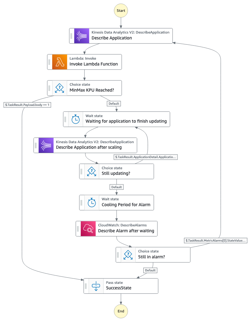
Let’s explore how serverless refactoring can enhance the design and runtime characteristics of a serverless application. The diagram below shows an AWS Step Functions workflow that performs a quality check through image recognition. An early implementation, shown on the left, would use an intermediate AWS Lambda function to call the Amazon Rekognition service. Thanks to the launch of Step Functions’ AWS SDK service integrations in 2021, you can refactor the workflow to directly call the Rekognition API. This refactored design, seen on the right, eliminates the Lambda function (assuming it didn’t perform any additional tasks), thereby reducing costs and runtime complexity.

Replacing Lambda with Service Integration in Step Function workflow

See the AWS CDK implementation for this refactoring, in TypeScript, on GitHub.

Refactoring Limitations

The initial example of replacing application code to send a message to SQS via Lambda Destinations reveals that refactoring from application to automation code isn’t 100% behavior-preserving.

First, Lambda Destinations are only triggered when the function is invoked asynchronously. For synchronous invocations, the function passes the results back to the caller, and does not invoke the destination. Second, the serverless runtime wraps the data returned from the function inside a message envelope, affecting how the message recipient parses the JSON object. The message data is placed inside the responsePayload field if sending to another Lambda function or the detail field if sending to an EventBridge destination. Last, Lambda Destinations sends a message after the function completes, whereas application code could send the message at any point during the execution.

Lambda Destination Execution

The last change in behavior will be transparent to well-architected asynchronous applications because they won’t depend on the timing of message delivery. If a Lambda function continues processing after sending a message (for example, to EventBridge), that code can’t assume that the message has been processed because delivery is asynchronous. A rare exception could be a loop waiting for the results from the downstream message processing, but such loops violate the principles of asynchronous integration and also waste compute resources (Amazon Step Functions is a great choice for asynchronous callbacks). If such behavior is required, it can be achieved by splitting the Lambda function into two parts.

Can Serverless Refactoring be Automated?

Traditional code refactoring like “Extract Method” is automated thanks to built-in support by many code editors. Serverless refactoring isn’t (yet) a fully automatic, 100%-equivalent code transformation because it translates application code into automation code (or vice versa). While AI-powered tools like Amazon Q Developer are getting us closer to that vision, we consider serverless refactoring primarily as a design technique for developers to better utilize the AWS runtime. Improved code design and runtime characteristics outweigh behavior differences, especially if your application includes automated tests.

Incorporating refactoring into your team structures

If a single team owns both the application and the automation code, refactoring takes place inside the team. However, serverless refactoring can cross team boundaries when separate teams develop business logic versus managing the underlying infrastructure, configuration, and deployment.

In such a model, AWS recommends that the development team be responsible for both the application code and the application-specific automation, such as the CDK code to configure Lambda Destinations, Step Functions workflows, or EventBridge routing. Splitting application and application-specific automation across teams would make the development team dependent on the platform team for each refactoring and introduce unnecessary friction.

If both teams use the same Infrastructure-as-Code (IaC) tool, say AWS CDK, the platform team can build reusable templates and constructs that encapsulate organizational requirements and guardrails, such as CDK constructs for S3 buckets with encryption enabled. Development teams can easily consume those resources across CDK stacks.

However, teams could use different IaC tools, for example, the infrastructure team prefers CloudFormation but the development team prefers AWS CDK. In this setup, development teams can build their automation on top of the CFN Modules provided by the infrastructure team. However, they won’t benefit from the same high-level programming abstractions as they do with CDK.

Collaboration in a split-team model

Continuous Refactoring

Just like traditional code refactoring, refactoring to serverless isn’t a one-time activity but an essential aspect of your software delivery. Because adding functionality increases your application’s complexity, regular refactoring can help keep complexity at bay and maintain your development velocity. Like with Continuous Delivery, you can improve your software delivery with Continuous Refactoring.

Teams who encounter difficulties with serverless refactoring might be lacking automated test coverage or cloud automation. So, refactoring can become a useful forcing function for teams to exercise software delivery hygiene, for example by implementing automated tests.

Getting Started

The refactoring samples discussed here are a subset of an extensive catalog of open source code examples, which you can find along with AWS CDK implementation examples at refactoringserverless.com. You can also dive deeper into how serverless refactoring can make your application architecture more loosely coupled in a separate blog post.

Use the examples to accelerate your own refactoring effort. Now Go Refactor!

Automate data loading from your database into Amazon Redshift using AWS Database Migration Service (DMS), AWS Step Functions, and the Redshift Data API

Post Syndicated from Ritesh Sinha original https://aws.amazon.com/blogs/big-data/automate-data-loading-from-your-database-into-amazon-redshift-using-aws-database-migration-service-dms-aws-step-functions-and-the-redshift-data-api/

Amazon Redshift is a fast, scalable, secure, and fully managed cloud data warehouse that makes it simple and cost-effective to analyze all your data using standard SQL and your existing ETL (extract, transform, and load), business intelligence (BI), and reporting tools. Tens of thousands of customers use Amazon Redshift to process exabytes of data per day and power analytics workloads such as BI, predictive analytics, and real-time streaming analytics.

As more and more data is being generated, collected, processed, and stored in many different systems, making the data available for end-users at the right place and right time is a very important aspect for data warehouse implementation. A fully automated and highly scalable ETL process helps minimize the operational effort that you must invest in managing the regular ETL pipelines. It also provides timely refreshes of data in your data warehouse.

You can approach the data integration process in two ways:

  • Full load – This method involves completely reloading all the data within a specific data warehouse table or dataset
  • Incremental load – This method focuses on updating or adding only the changed or new data to the existing dataset in a data warehouse

This post discusses how to automate ingestion of source data that changes completely and has no way to track the changes. This is useful for customers who want to use this data in Amazon Redshift; some examples of such data are products and bills of materials without tracking details at the source.

We show how to build an automatic extract and load process from various relational database systems into a data warehouse for full load only. A full load is performed from SQL Server to Amazon Redshift using AWS Database Migration Service (AWS DMS). When Amazon EventBridge receives a full load completion notification from AWS DMS, ETL processes are run on Amazon Redshift to process data. AWS Step Functions is used to orchestrate this ETL pipeline. Alternatively, you could use Amazon Managed Workflows for Apache Airflow (Amazon MWAA), a managed orchestration service for Apache Airflow that makes it straightforward to set up and operate end-to-end data pipelines in the cloud.

Solution overview

The workflow consists of the following steps:

  1. The solution uses an AWS DMS migration task that replicates the full load dataset from the configured SQL Server source to a target Redshift cluster in a staging area.
  2. AWS DMS publishes the replicationtaskstopped event to EventBridge when the replication task is complete, which invokes an EventBridge rule.
  3. EventBridge routes the event to a Step Functions state machine.
  4. The state machine calls a Redshift stored procedure through the Redshift Data API, which loads the dataset from the staging area to the target production tables. With this API, you can also access Redshift data with web-based service applications, including AWS Lambda.

The following architecture diagram highlights the end-to-end solution using AWS services.

In the following sections, we demonstrate how to create the full load AWS DMS task, configure the ETL orchestration on Amazon Redshift, create the EventBridge rule, and test the solution.

Prerequisites

To complete this walkthrough, you must have the following prerequisites:

  • An AWS account
  • A SQL Server database configured as a replication source for AWS DMS
  • A Redshift cluster to serve as the target database
  • An AWS DMS replication instance to migrate data from source to target
  • A source endpoint pointing to the SQL Server database
  • A target endpoint pointing to the Redshift cluster

Create the full load AWS DMS task

Complete the following steps to set up your migration task:

  1. On the AWS DMS console, choose Database migration tasks in the navigation pane.
  2. Choose Create task.
  3. For Task identifier, enter a name for your task, such as dms-full-dump-task.
  4. Choose your replication instance.
  5. Choose your source endpoint.
  6. Choose your target endpoint.
  7. For Migration type, choose Migrate existing data.

  1. In the Table mapping section, under Selection rules, choose Add new selection rule
  2. For Schema, choose Enter a schema.
  3. For Schema name, enter a name (for example, dms_sample).
  4. Keep the remaining settings as default and choose Create task.

The following screenshot shows your completed task on the AWS DMS console.

Create Redshift tables

Create the following tables on the Redshift cluster using the Redshift query editor:

  • dbo.dim_cust – Stores customer attributes:
CREATE TABLE dbo.dim_cust (
cust_key integer ENCODE az64,
cust_id character varying(10) ENCODE lzo,
cust_name character varying(100) ENCODE lzo,
cust_city character varying(50) ENCODE lzo,
cust_rev_flg character varying(1) ENCODE lzo
)

DISTSTYLE AUTO;
  • dbo.fact_sales – Stores customer sales transactions:
CREATE TABLE dbo.fact_sales (
order_number character varying(20) ENCODE lzo,
cust_key integer ENCODE az64,
order_amt numeric(18,2) ENCODE az64
)

DISTSTYLE AUTO;
  • dbo.fact_sales_stg – Stores daily customer incremental sales transactions:
CREATE TABLE dbo.fact_sales_stg (
order_number character varying(20) ENCODE lzo,
cust_id character varying(10) ENCODE lzo,
order_amt numeric(18,2) ENCODE az64
)

DISTSTYLE AUTO;

Use the following INSERT statements to load sample data into the sales staging table:

insert into dbo.fact_sales_stg(order_number,cust_id,order_amt) values (100,1,200);
insert into dbo.fact_sales_stg(order_number,cust_id,order_amt) values (101,1,300);
insert into dbo.fact_sales_stg(order_number,cust_id,order_amt) values (102,2,25);
insert into dbo.fact_sales_stg(order_number,cust_id,order_amt) values (103,2,35);
insert into dbo.fact_sales_stg(order_number,cust_id,order_amt) values (104,3,80);
insert into dbo.fact_sales_stg(order_number,cust_id,order_amt) values (105,3,45);

Create the stored procedures

In the Redshift query editor, create the following stored procedures to process customer and sales transaction data:

  • Sp_load_cust_dim() – This procedure compares the customer dimension with incremental customer data in staging and populates the customer dimension:
CREATE OR REPLACE PROCEDURE dbo.sp_load_cust_dim()
LANGUAGE plpgsql
AS $$
BEGIN
truncate table dbo.dim_cust;
insert into dbo.dim_cust(cust_key,cust_id,cust_name,cust_city) values (1,100,'abc','chicago');
insert into dbo.dim_cust(cust_key,cust_id,cust_name,cust_city) values (2,101,'xyz','dallas');
insert into dbo.dim_cust(cust_key,cust_id,cust_name,cust_city) values (3,102,'yrt','new york');
update dbo.dim_cust
set cust_rev_flg=case when cust_city='new york' then 'Y' else 'N' end
where cust_rev_flg is null;
END;
$$
  • sp_load_fact_sales() – This procedure does the transformation for incremental order data by joining with the date dimension and customer dimension and populates the primary keys from the respective dimension tables in the final sales fact table:
CREATE OR REPLACE PROCEDURE dbo.sp_load_fact_sales()
LANGUAGE plpgsql
AS $$
BEGIN
--Process Fact Sales
insert into dbo.fact_sales
select
sales_fct.order_number,
cust.cust_key as cust_key,
sales_fct.order_amt
from dbo.fact_sales_stg sales_fct
--join to customer dim
inner join (select * from dbo.dim_cust) cust on sales_fct.cust_id=cust.cust_id;
END;
$$

Create the Step Functions state machine

Complete the following steps to create the state machine redshift-elt-load-customer-sales. This state machine is invoked as soon as the AWS DMS full load task for the customer table is complete.

  1. On the Step Functions console, choose State machines in the navigation pane.
  2. Choose Create state machine.
  3. For Template, choose Blank.
  4. On the Actions dropdown menu, choose Import definition to import the workflow definition of the state machine.

  1. Open your preferred text editor and save the following code as an ASL file extension (for example, redshift-elt-load-customer-sales.ASL). Provide your Redshift cluster ID and the secret ARN for your Redshift cluster.
{
"Comment": "State Machine to process ETL for Customer Sales Transactions",
"StartAt": "Load_Customer_Dim",
"States": {
"Load_Customer_Dim": {
"Type": "Task",
"Parameters": {
"ClusterIdentifier": "redshiftcluster-abcd",
"Database": "dev",
"Sql": "call dbo.sp_load_cust_dim()",
"SecretArn": "arn:aws:secretsmanager:us-west-2:xxx:secret:rs-cluster-secret-abcd"
},
"Resource": "arn:aws:states:::aws-sdk:redshiftdata:executeStatement",
"Next": "Wait on Load_Customer_Dim"
},
"Wait on Load_Customer_Dim": {
"Type": "Wait",
"Seconds": 30,
"Next": "Check_Status_Load_Customer_Dim"
},

"Check_Status_Load_Customer_Dim": {
"Type": "Task",
"Next": "Choice",
"Parameters": {
"Id.$": "$.Id"
},

"Resource": "arn:aws:states:::aws-sdk:redshiftdata:describeStatement"
},

"Choice": {
"Type": "Choice",
"Choices": [
{
"Not": {
"Variable": "$.Status",
"StringEquals": "FINISHED"
},
"Next": "Wait on Load_Customer_Dim"
}
],
"Default": "Load_Sales_Fact"
},
"Load_Sales_Fact": {
"Type": "Task",
"End": true,
"Parameters": {
"ClusterIdentifier": "redshiftcluster-abcdef”,
"Database": "dev",
"Sql": "call dbo.sp_load_fact_sales()",
"SecretArn": "arn:aws:secretsmanager:us-west-2:xxx:secret:rs-cluster-secret-abcd"
},

"Resource": "arn:aws:states:::aws-sdk:redshiftdata:executeStatement"
}
}
}
  1. Choose Choose file and upload the ASL file to create a new state machine.

  1. For State machine name, enter a name for the state machine (for example, redshift-elt-load-customer-sales).
  2. Choose Create.

After the successful creation of the state machine, you can verify the details as shown in the following screenshot.

The following diagram illustrates the state machine workflow.

The state machine includes the following steps:

  • Load_Customer_Dim – Performs the following actions:
    • Passes the stored procedure sp_load_cust_dim to the execute-statement API to run in the Redshift cluster to load the incremental data for the customer dimension
    • Sends data back the identifier of the SQL statement to the state machine
  • Wait_on_Load_Customer_Dim – Waits for at least 15 seconds
  • Check_Status_Load_Customer_Dim – Invokes the Data API’s describeStatement to get the status of the API call
  • is_run_Load_Customer_Dim_complete – Routes the next step of the ETL workflow depending on its status:
    • FINISHED – Passes the stored procedure Load_Sales_Fact to the execute-statement API to run in the Redshift cluster, which loads the incremental data for fact sales and populates the corresponding keys from the customer and date dimensions
    • All other statuses – Goes back to the wait_on_load_customer_dim step to wait for the SQL statements to finish

The state machine redshift-elt-load-customer-sales loads the dim_cust, fact_sales_stg, and fact_sales tables when invoked by the EventBridge rule.

As an optional step, you can set up event-based notifications on completion of the state machine to invoke any downstream actions, such as Amazon Simple Notification Service (Amazon SNS) or further ETL processes.

Create an EventBridge rule

EventBridge sends event notifications to the Step Functions state machine when the full load is complete. You can also turn event notifications on or off in EventBridge.

Complete the following steps to create the EventBridge rule:

  1. On the EventBridge console, in the navigation pane, choose Rules.
  2. Choose Create rule.
  3. For Name, enter a name (for example, dms-test).
  4. Optionally, enter a description for the rule.
  5. For Event bus, choose the event bus to associate with this rule. If you want this rule to match events that come from your account, select AWS default event bus. When an AWS service in your account emits an event, it always goes to your account’s default event bus.
  6. For Rule type, choose Rule with an event pattern.
  7. Choose Next.
  8. For Event source, choose AWS events or EventBridge partner events.
  9. For Method, select Use pattern form.
  10. For Event source, choose AWS services.
  11. For AWS service, choose Database Migration Service.
  12. For Event type, choose All Events.
  13. For Event pattern, enter the following JSON expression, which looks for the REPLICATON_TASK_STOPPED status for the AWS DMS task:
{
"source": ["aws.dms"],
"detail": {
"eventId": ["DMS-EVENT-0079"],
"eventType": ["REPLICATION_TASK_STOPPED"],
"detailMessage": ["Stop Reason FULL_LOAD_ONLY_FINISHED"],
"type": ["REPLICATION_TASK"],
"category": ["StateChange"]
}
}

  1. For Target type, choose AWS service.
  2. For AWS service, choose Step Functions state machine.
  3. For State machine name, enter redshift-elt-load-customer-sales.
  4. Choose Create rule.

The following screenshot shows the details of the rule created for this post.

Test the solution

Run the task and wait for the workload to complete. This workflow moves the full volume data from the source database to the Redshift cluster.

The following screenshot shows the load statistics for the customer table full load.

AWS DMS provides notifications when an AWS DMS event occurs, for example the completion of a full load or if a replication task has stopped.

After the full load is complete, AWS DMS sends events to the default event bus for your account. The following screenshot shows an example of invoking the target Step Functions state machine using the rule you created.

We configured the Step Functions state machine as a target in EventBridge. This enables EventBridge to invoke the Step Functions workflow in response to the completion of an AWS DMS full load task.

Validate the state machine orchestration

When the entire customer sales data pipeline is complete, you may go through the entire event history for the Step Functions state machine, as shown in the following screenshots.

Limitations

The Data API and Step Functions AWS SDK integration offers a robust mechanism to build highly distributed ETL applications within minimal developer overhead. Consider the following limitations when using the Data API and Step Functions:

Clean up

To avoid incurring future charges, delete the Redshift cluster, AWS DMS full load task, AWS DMS replication instance, and Step Functions state machine that you created as part of this post.

Conclusion

In this post, we demonstrated how to build an ETL orchestration for full loads from operational data stores using the Redshift Data API, EventBridge, Step Functions with AWS SDK integration, and Redshift stored procedures.

To learn more about the Data API, see Using the Amazon Redshift Data API to interact with Amazon Redshift clusters and Using the Amazon Redshift Data API.


About the authors

Ritesh Kumar Sinha is an Analytics Specialist Solutions Architect based out of San Francisco. He has helped customers build scalable data warehousing and big data solutions for over 16 years. He loves to design and build efficient end-to-end solutions on AWS. In his spare time, he loves reading, walking, and doing yoga.

Praveen Kadipikonda is a Senior Analytics Specialist Solutions Architect at AWS based out of Dallas. He helps customers build efficient, performant, and scalable analytic solutions. He has worked with building databases and data warehouse solutions for over 15 years.

Jagadish Kumar (Jag) is a Senior Specialist Solutions Architect at AWS focused on Amazon OpenSearch Service. He is deeply passionate about Data Architecture and helps customers build analytics solutions at scale on AWS.

Serverless ICYMI Q2 2024

Post Syndicated from Julian Wood original https://aws.amazon.com/blogs/compute/serverless-icymi-q2-2024/

Welcome to the 26th edition of the AWS Serverless ICYMI (in case you missed it) quarterly recap. Every quarter, we share all the most recent product launches, feature enhancements, blog posts, webinars, live streams, and other interesting things that you might have missed!

In case you missed our last ICYMI, check out what happened last quarter here.

Calendar

Calendar

EDA Day – London 2024

The AWS Serverless DA team hosted the third Event-Driven Architecture (EDA) Day in London on May 14th. This event brought together prominent figures in the event-driven architecture community, AWS, and customer speakers.

EDA Day covered 13 sessions, 2 workshops, and a Q&A panel. David Boyne was the keynote speaker with a talk “Complexity is the Gotcha of Event-Driven Architecture”. There were AWS speakers including Matthew Meckes, Natasha Wright, Julian Wood, Gillian Amstrong, Josh Kahn, Veda Ramen, and Uma Ramadoss. There was also an impressive lineup of guest speakers, Daniele Frasca, David Anderson, Ryan Cormack, Sarah Hamilton, Sheen Brisals, Marcin Sodkiewicz, and Ben Ellerby.

Videos are available on YouTube

EDA Day London

EDA Day London

The future of Serverless

There has been a lot of talk about the future of serverless, with this year being the 10th anniversary of AWS Lambda. Eric Johnson addresses the topic in his ServerlessDays Milan keynote, “Now serverless is all grown up, what’s next”.

AWS Lambda

AWS launched support for the latest release of Ruby 3.3 is based on the new Amazon Linux 2023 runtime. The Ruby 3.3 runtime also provides access to the latest Ruby language features.

There is a new guide on how to retrieve data about Lambda functions that use a deprecated runtime.

Learn how to run code after returning a response from an AWS Lambda function. This post shows how to return a synchronous function response as soon as possible, yet also perform additional asynchronous work after you send the response. For example, you may store data in a database or send information to a logging system.

See how you can use the circuit-breaker pattern with Lambda extensions and Amazon DynamoDB. The circuit breaker pattern can help prevent cascading failures and improve overall system stability.

Circuit-breaker pattern

Circuit-breaker pattern

Lambda functions now scale up to 12X faster in the AWS GovCloud (US) Regions.

Powertools for AWS Lambda (Python) adds support for Agents for Amazon Bedrock.

The AWS SDK for JavaScript v2 enters maintenance mode on September 8, 2024 and reaches end-of-support on September 8, 2025.

Amazon CloudWatch Logs introduced Live Tail streaming CLI support.

Amazon ECS and AWS Fargate

You can now secure Amazon Elastic Container Service (Amazon ECS) workloads on AWS Fargate with customer managed keys (CMKs). Once you add your keys to AWS Key Management Service (AWS KMS), you can use these to encrypt the underlying ephemeral storage of an Amazon ECS task on AWS Fargate.

Windows containers on AWS Fargate now start faster, up to 42% for Windows Server 2022 Core. AWS has optimized the Windows Server AMIs, introduced EC2 fast launch with pre-provisioned snapshots, and reduced network latency.

Amazon ECS Service Connect is a networking capability to simplify service discovery, connectivity, and traffic observability for Amazon ECS. You can now proactively scale Amazon ECS services by using custom metrics.

ECS Connect custom metrics

ECS Service Connect custom metrics

AWS Step Functions

The AWS Step Functions TestState API allows you to test individual states independently and to integrate testing into your preferred development workflows. Learn how to accelerate workflow development to iterate faster.

Step Functions TestState API

Step Functions TestState API

Amazon EventBridge

Amazon EventBridge Pipes now supports event delivery through AWS PrivateLink. You can send events from an event source located in an Amazon Virtual Private Cloud (VPC) to a Pipes target without traversing the public internet.

Amazon Timestream for LiveAnalytics is now an EventBridge Pipes target. Timestream for LiveAnalytics is a fast, scalable, purpose-built time series database that makes it easy to store and analyze trillions of time series data points per day.

EventBridge has a new console dashboard which provides a centralized view of your resources, metrics, and quotas. The console has an improved Learn page and other console enhancements. When using the CloudFormation template export for Pipes, you can also generate the IAM role. There is a new Rules tab in the Event Bus detail page, and the monitoring tab in the Rule detail page now includes additional metrics.

EventBridge Scheduler has some new API request metrics for improved observability.

Generative AI

Amazon Bedrock is a fully managed Generative AI service that offers a choice of high-performing foundation models (FMs) from leading AI companies through a single API. Bedrock now supports new models, including Anthropic’s Claude 3.5, AI21 Labs’ Jamba-Instruct, Amazon Titan Text Premier.

The new Bedrock Converse API provides a consistent way to invoke Amazon Bedrock models and simplifies multi-turn conversations. There is also a JavaScript tutorial to walk you through sending requests to the Converse API using the Javascript SDK.

Amazon Q Developer is now generally available. Amazon Q Developer, part of the Amazon Q family, is a generative AI–powered assistant for software development. Amazon Q is available in the AWS Management Console and as an integrated development environment (IDE) extension for Visual Studio Code, Visual Studio, and JetBrains IDEs. Amazon Q Developer has knowledge of your AWS account resources and can help understand your costs.

Amazon Q list Lambda functions

Amazon Q list Lambda functions

You can use Amazon Q Developer to develop code features and transform code to upgrade Java applications. Amazon Q Developer also offers inline completions in the command line. For more information, see Reimagining software development with the Amazon Q Developer Agent.

Amazon Q code features

Amazon Q code features

Knowledge Bases for Amazon Bedrock now let you configure Guardrails, configure inference parameters, and offers observability logs.

Storage and data

Amazon S3 no longer charges for several HTTP error codes if initiated from outside your individual AWS account or AWS Organization.

You can automatically detect malware in new object uploads to S3 with Amazon GuardDuty.

Amazon Elastic File System (Amazon EFS) now support up to 1.5 GiB/s of throughput per client, a 3x increase over the previous limit of 500 MiB/s.

Discover architectural patterns for real-time analytics using Amazon Kinesis Data Streams in part 1 and part 2 and see how to optimize write throughput.

Amazon API Gateway

Amazon API Gateway now allows you to increase the integration timeout beyond the prior limit of 29 seconds. You can raise the integration timeout for Regional and private REST APIs, but this might require a reduction in your account-level throttle quota limit. This launch can help with workloads that require longer timeouts, such as Generative AI use cases with Large Language Models (LLMs).

You can also now use Amazon Verified Permissions to secure API Gateway REST APIs when using an Open ID connect (OIDC) compliant identity provider. You can now control access based on user attributes and group memberships, without writing code.

AWS AppSync

You can now invoke your AWS AppSync data sources in an event-driven manner. Previously, you could only invoke Lambda functions synchronously from AWS AppSync. AWS AppSync can now trigger Lambda functions in Event mode, asynchronously decoupling the API response from the Lambda invocation, which helps with long-running operations.

AWS AppSync now passes application request headers to Lambda custom authorizer functions. You can make authorization decisions based on the value of the authorization header, and the value of other headers that were sent with the request from the application client.

Learn best practices for AWS AppSync GraphQL APIs. See how to how to optimize the security, performance, coding standards, and deployment of your AWS AppSync API. AWS AppSync also has increase quotas, and new metrics

AWS Amplify

AWS Amplify Gen 2 is now generally available. This now provides a code-first developer experience for building full-stack apps using TypeScript. Amplify Gen 2 allows you to express app requirements like the data models, business logic, and authorization rules in TypeScript.

AWS Amplify Gen2

AWS Amplify Gen2

Amplify has a new experience for file storage. This post explores using Lambda to create serverless functions for Amplify using TypeScript. There are also new team environment workflows.

Serverless blog posts

April

May

June

Serverless container blog posts

April

May

June

Serverless Office Hours

Serverless Office Hours

Serverless Office Hours

April

May

June

Containers from the Couch

Containers from the Couch

Containers from the Couch

April

May

FooBar Serverless

April

February

June

Still looking for more?

The Serverless landing page has more information. The Lambda resources page contains case studies, webinars, whitepapers, customer stories, reference architectures, and even more Getting Started tutorials.

You can also follow the Serverless Developer Advocacy team on X (formerly Twitter) to see the latest news, follow conversations, and interact with the team.

And finally, visit the Serverless Land and Containers on AWS websites for all your serverless and serverless container needs.

Disaster recovery strategies for Amazon MWAA – Part 2

Post Syndicated from Chandan Rupakheti original https://aws.amazon.com/blogs/big-data/disaster-recovery-strategies-for-amazon-mwaa-part-2/

Amazon Managed Workflows for Apache Airflow (Amazon MWAA) is a fully managed orchestration service that makes it straightforward to run data processing workflows at scale. Amazon MWAA takes care of operating and scaling Apache Airflow so you can focus on developing workflows. However, although Amazon MWAA provides high availability within an AWS Region through features like Multi-AZ deployment of Airflow components, recovering from a Regional outage requires a multi-Region deployment.

In Part 1 of this series, we highlighted challenges for Amazon MWAA disaster recovery and discussed best practices to improve resiliency. In particular, we discussed two key strategies: backup and restore and warm standby. In this post, we dive deep into the implementation for both strategies and provide a deployable solution to realize the architectures in your own AWS account.

The solution for this post is hosted on GitHub. The README in the repository offers tutorials as well as further workflow details for both backup and restore and warm standby strategies.

Backup and restore architecture

The backup and restore strategy involves periodically backing up Amazon MWAA metadata to Amazon Simple Storage Service (Amazon S3) buckets in the primary Region. The backups are replicated to an S3 bucket in the secondary Region. In case of a failure in the primary Region, a new Amazon MWAA environment is created in the secondary Region and hydrated with the backed-up metadata to restore the workflows.

The project uses the AWS Cloud Development Kit (AWS CDK) and is set up like a standard Python project. Refer to the detailed deployment steps in the README file to deploy it in your own accounts.

The following diagram shows the architecture of the backup and restore strategy and its key components:

  • Primary Amazon MWAA environment – The environment in the primary Region hosts the workflows
  • Metadata backup bucket – The bucket in the primary Region stores periodic backups of Airflow metadata tables
  • Replicated backup bucket – The bucket in the secondary Region syncs metadata backups through Amazon S3 cross-Region replication
  • Secondary Amazon MWAA environment – This environment is created on-demand during recovery in the secondary Region
  • Backup workflow – This workflow periodically backups up Airflow metadata to the S3 buckets in the primary Region
  • Recovery workflow – This workflow monitors the primary Amazon MWAA environment and initiates failover when needed in the secondary Region


The backup restore architecture

Figure 1: The backup restore architecture

There are essentially two workflows that work in conjunction to achieve the backup and restore functionality in this architecture. Let’s explore both workflows in detail and the steps as outlined in Figure 1.

Backup workflow

The backup workflow is responsible for periodically taking a backup of your Airflow metadata tables and storing them in the backup S3 bucket. The steps are as follows:

  • [1.a] You can deploy the provided solution from your continuous integration and delivery (CI/CD) pipeline. The pipeline includes a DAG deployed to the DAGs S3 bucket, which performs backup of your Airflow metadata. This is the bucket where you host all of your DAGs for your environment.
  • [1.b] The solution enables cross-Region replication of the DAGs bucket. Any new changes to the primary Region bucket, including DAG files, plugins, and requirements.txt files, are replicated to the secondary Region DAGs bucket. However, for existing objects, a one-time replication needs to be performed using S3 Batch Replication.
  • [1.c] The DAG deployed to take metadata backup runs periodically. The metadata backup doesn’t include some of the auto-generated tables and the list of tables to be backed up is configurable. By default, the solution backs up variable, connection, slot pool, log, job, DAG run, trigger, task instance, and task fail tables. The backup interval is also configurable and should be based on the Recovery Point Objective (RPO), which is the data loss time during a failure that can be sustained by your business.
  • [1.d] Similar to the DAGs bucket, the backup bucket is also synced using cross-Region replication, through which the metadata backup becomes available in the secondary Region.

Recovery workflow

The recovery workflow runs periodically in the secondary Region monitoring the primary Amazon MWAA environment. It has two functions:

  • Store the environment configuration of the primary Amazon MWAA environment in the secondary backup bucket, which is used to recreate an identical Amazon MWAA environment in the secondary Region during failure
  • Perform the failover when a failure is detected

The following are the steps for when the primary Amazon MWAA environment is healthy (see Figure 1):

  • [2.a] The Amazon EventBridge scheduler starts the AWS Step Functions workflow on a provided schedule.
  • [2.b] The workflow, using AWS Lambda, checks Amazon CloudWatch in the primary Region for the SchedulerHeartbeat metrics of the primary Amazon MWAA environment. The environment in the primary Region sends heartbeats to CloudWatch every 5 seconds by default. However, to not invoke a recovery workflow spuriously, we use a default aggregation period of 5 minutes to check the heartbeat metrics. Therefore, it can take up to 5 minutes to detect a primary environment failure.
  • [2.c] Assuming that the heartbeat was detected in 2.b, the workflow makes the cross-Region GetEnvironment call to the primary Amazon MWAA environment.
  • [2.d] The response from the GetEnvironment call is stored in the secondary backup S3 bucket to be used in case of a failure in the subsequent iterations of the workflow. This makes sure the latest configuration of your primary environment is used to recreate a new environment in the secondary Region. The workflow completes successfully after storing the configuration.

The following are the steps for the case when the primary environment is unhealthy (see Figure 1):

  • [2.a] The EventBridge scheduler starts the Step Functions workflow on a provided schedule.
  • [2.b] The workflow, using Lambda, checks CloudWatch in the primary Region for the scheduler heartbeat metrics and detects failure. The scheduler heartbeat check using the CloudWatch API is the recommended approach to detect failure. However, you can implement a custom strategy for failure detection in the Lambda function such as deploying a DAG to periodically send custom metrics to CloudWatch or other data stores as heartbeats and using the function to check that metrics. With the current CloudWatch-based strategy, the unavailability of the CloudWatch API may spuriously invoke the recovery flow.
  • [2.c] Skipped
  • [2.d] The workflow reads the previously stored environment details from the backup S3 bucket.
  • [2.e] The environment details read from the previous step is used to recreate an identical environment in the secondary Region using the CreateEnvironment API call. The API also needs other secondary Region specific configurations such as VPC, subnets, and security groups that are read from the user-supplied configuration file or environment variables during the solution deployment. The workflow in a polling loop waits until the environment becomes available and invokes the DAG to restore metadata from the backup S3 bucket. This DAG is deployed to the DAGs S3 bucket as a part of the solution deployment.
  • [2.f] The DAG for restoring metadata completes hydrating the newly created environment and notifies the Step Functions workflow of completion using the task token integration. The new environment now starts running the active workflows and the recovery completes successfully.

Considerations

Consider the following when using the backup and restore method:

  • Recovery Time Objective – From failure detection to workflows running in the secondary Region, failover can take over 30 minutes. This includes new environment creation, Airflow startup, and metadata restore.
  • Cost – This strategy avoids the overhead of running a passive environment in the secondary Region. Costs are limited to periodic backup storage, cross-Region data transfer charges, and minimal compute for the recovery workflow.
  • Data loss – The RPO depends on the backup frequency. There is a design trade-off to consider here. Although shorter intervals between backups can minimize potential data loss, too frequent backups can adversely affect the performance of the metadata database and consequently the primary Airflow environment. Also, the solution can’t recover an actively running workflow midway. All active workflows are started fresh in the secondary Region based on the provided schedule.
  • Ongoing management – The Amazon MWAA environment and dependencies are automatically kept in sync across Regions in this architecture. As specified in the Step 1.b of the backup workflow, the DAGs S3 bucket will need a one-time deployment of the existing resources for the solution to work.

Warm standby architecture

The warm standby strategy involves deploying identical Amazon MWAA environments in two Regions. Periodic metadata backups from the primary Region are used to rehydrate the standby environment in case of failover.

The project uses the AWS CDK and is set up like a standard Python project. Refer to the detailed deployment steps in the README file to deploy it in your own accounts.

The following diagram shows the architecture of the warm standby strategy and its key components:

  • Primary Amazon MWAA environment – The environment in the primary Region hosts the workflows during normal operation
  • Secondary Amazon MWAA environment – The environment in the secondary Region acts as a warm standby ready to take over at any time
  • Metadata backup bucket – The bucket in the primary Region stores periodic backups of Airflow metadata tables
  • Replicated backup bucket – The bucket in the secondary Region syncs metadata backups through S3 Cross-Region Replication.
  • Backup workflow – This workflow periodically backups up Airflow metadata to the S3 buckets in both Regions
  • Recovery workflow – This workflow monitors the primary environment and initiates failover to the secondary environment when needed


The warm standby architecture

Figure 2: The warm standby architecture

Similar to the backup and restore strategy, the backup workflow (Steps 1a–1d) periodically backups up critical Amazon MWAA metadata to S3 buckets in the primary Region, which is synced in the secondary Region.

The recovery workflow runs periodically in the secondary Region monitoring the primary environment. On failure detection, it initiates the failover procedure. The steps are as follows (see Figure 2):

  • [2.a] The EventBridge scheduler starts the Step Functions workflow on a provided schedule.
  • [2.b] The workflow checks CloudWatch in the primary Region for the scheduler heartbeat metrics and detects failure. If the primary environment is healthy, the workflow completes without further actions.
  • [2.c] The workflow invokes the DAG to restore metadata from the backup S3 bucket.
  • [2.d] The DAG for restoring metadata completes hydrating the passive environment and notifies the Step Functions workflow of completion using the task token integration. The passive environment starts running the active workflows on the provided schedules.

Because the secondary environment is already warmed up, the failover is faster with recovery times in minutes.

Considerations

Consider the following when using the warm standby method:

  • Recovery Time Objective – With a warm standby ready, the RTO can be as low as 5 minutes. This includes just the metadata restore and reenabling DAGs in the secondary Region.
  • Cost – This strategy has an added cost of running similar environments in two Regions at all times. With auto scaling for workers, the warm instance can maintain a minimal footprint; however, the web server and scheduler components of Amazon MWAA will remain active in the secondary environment at all times. The trade-off is significantly lower RTO.
  • Data loss – Similar to the backup and restore model, the RPO depends on the backup frequency. Faster backup cycles minimize potential data loss but can adversely affect performance of the metadata database and consequently the primary Airflow environment.
  • Ongoing management – This approach comes with some management overhead. Unlike the backup and restore strategy, any changes to the primary environment configurations need to be manually reapplied to the secondary environment to keep the two environments in sync. Automated synchronization of the secondary environment configurations is a future work.

Shared considerations

Although the backup and restore and warm standby strategies differ in their implementation, they share some common considerations:

  • Periodically test failover to validate recovery procedures, RTO, and RPO.
  • Enable Amazon MWAA environment logging to help debug issues during failover.
  • Use the AWS CDK or AWS CloudFormation to manage the infrastructure definition. For more details, see the following GitHub repo or Quick start tutorial for Amazon Managed Workflows for Apache Airflow, respectively.
  • Automate deployments of environment configurations and disaster recovery workflows through CI/CD pipelines.
  • Monitor key CloudWatch metrics like SchedulerHeartbeat to detect primary environment failures.

Conclusion

In this series, we discussed how backup and restore and warm standby strategies offer configurable data protection based on your RTO, RPO, and cost requirements. Both use periodic metadata replication and restoration to minimize the area of effect of Regional outages.

Which strategy resonates more with your use case? Feel free to try out our solution and share any feedback or questions in the comments section!


About the Authors

Chandan RupakhetiChandan Rupakheti is a Senior Solutions Architect at AWS. His main focus at AWS lies in the intersection of Analytics, Serverless, and AdTech services. He is a passionate technical leader, researcher, and mentor with a knack for building innovative solutions in the cloud. Outside of his professional life, he loves spending time with his family and friends besides listening and playing music.

Parnab Basak is a Senior Solutions Architect and a Serverless Specialist at AWS. He specializes in creating new solutions that are cloud native using modern software development practices like serverless, DevOps, and analytics. Parnab works closely in the analytics and integration services space helping customers adopt AWS services for their workflow orchestration needs.

Accelerating workflow development with the TestState API in AWS Step Functions

Post Syndicated from James Beswick original https://aws.amazon.com/blogs/compute/accelerating-workflow-development-with-the-teststate-api-in-aws-step-functions/

This post is written by Ben Freiberg, Senior Solutions Architect.

Developers often choose AWS Step Functions to orchestrate the services that comprise their applications. Step Functions is a visual workflow service that makes it easier for developers to build distributed applications, automate processes, orchestrate microservices, and create data and machine learning (ML) pipelines. Step Functions integrates with over 220 AWS services and any publicly accessible HTTP endpoint. Step Functions provides many features that help developers build, such as built-in error handling, real-time and auditable workflow execution history, and large-scale parallel processing.

Several areas can be time consuming for developers when testing Step Functions workflows. For example, authentication with external services, input/output processing, AWS IAM permission, or intrinsic functions. To simplify and speed up resolving these issues, Step Functions released a new capability last year to test individual states: the TestState API. This feature allows you to test states independently from the execution of your workflow. You can change the input and test different scenarios without the need to deploy your workflow or execute the whole state machine. This feature is available for all task, choice, and pass states.

Since developers spend significant time in IDEs and terminals, TestState is also available via an API. This allows you to iterate over changes for an individual state and lets you refine the input/output processing or conditional logic in a choice state without leaving your IDE. In this post, you’ll learn how the TestState API can speed up your testing and development.

Getting started with TestState

Suppose that you are developing a payment processing workflow that consists of three states. First, a Choice state that checks the type of payment based on the input data. Depending on the type, it calls either an AWS Lambda function or an external endpoint. The task state that invokes the Lambda function includes some input/output processing.

Getting started with TestState

To get started with the TestState API, you must create an IAM role that the service can assume. The role must contain the required IAM permissions for the resources your state is accessing. For information about the permissions a state might need, see IAM permissions to test a state. The following snippet shows the minimal necessary permissions:

{
  "Version": "2012-10-17",
  "Statement": [
    {
      "Effect": "Allow",
      "Action": [
        "states:TestState",
        "iam:PassRole"
      ],
      "Resource": "*"
    }
  ]
}

Next, you must provide the definition of the state being tested. The choice state is configured to check the type of payment and if the voucherId is present, in case of a voucher. The following snippet shows the state definition:

{
    "Type": "Choice",
    "Choices": [
        {
            "And": [
                {
                    "Variable": "$.payment.type",
                    "IsPresent": true
                },
                {
                    "Variable": "$.payment.type",
                    "StringEquals": "voucher"
                }
            ],
            "Next": "Process voucher"
        },
        {
            "Variable": "$.payment.type",
            "StringEquals": "credit",
            "Next": "Call payment provider"
        }
    ],
    "Default": "Fail"
}

Using the role and state definition, you can now test it if an input results in the expected next state:

aws stepfunctions test-state 
--definition file://choice.json 
--role-arn "arn:aws:iam::<account-id>:role/StepFunctions-TestState-Role" 
--input '{"payment":{"type":"voucher"}}'

The response shows that the test did not encounter any errors and that the next state would be invoking the Lambda function to process the voucher as expected.

{
    "output": "{\"payment\":{\"type\":\"voucher\"}}",
    "nextState": "Process voucher",
    "status": "SUCCEEDED"
}

Similarly, with a payment type of credit as input, the next state is invoking the third-party endpoint:

aws stepfunctions test-state
--definition file://choice.json
--role-arn "arn:aws:iam::<account-id>:role/StepFunctions-TestState-Role"
--input '{"payment":{"type":"credit"}}'
{
    "output": "{\"payment\":{\"type\":\"credit\"}}",
    "nextState": "Call payment provider",
    "status": "SUCCEEDED"
}

Because the TestState API takes the state definition as an argument, you do not have to redeploy the state machine when changing the state definition. Instead, you can iterate and test your settings by passing the modified state definition to the TestState API.

Using inspection levels

For each state, you can specify the amount of detail you want to view in the test results. These details provide additional information about the state that you are testing. For example, if you’ve used any input and output data processing filters, such as InputPath or ResultPath in a state, you can view the intermediate and final data processing results. Step Functions provides the following levels to specify the details you want to view, INFODEBUG, and TRACE. All these levels return the status and nextState fields.

Next, the Lambda Invoke state is tested. In this scenario, the state includes input/output processing. The output from the function is transformed by renaming and restructuring the field and then merged with the original input. This is the relevant part of the task definition:

"Process voucher": {
      "Type": "Task",
      "Resource": "arn:aws:states:::lambda:invoke",
      "Parameters": {...},
      "Retry": [...],
      "Next": "Success",
      "ResultPath": "$.voucherProcessed",
      "ResultSelector": {
        "status.$": "$.Payload.result",
        "workflowId.$": "$.Payload.workflow"
      }
}

This time test using the Step Functions console, which can make it easier to understand the input/output processing steps. To get started, open the state machine in Workflow Studio and select the state, and then choose Test State. Make sure to select DEBUG as the inspection level. After testing the state, switch to the Input/output processing tab to check the intermediate steps.

Input/output processing tab

When you call the TestState API and set the inspectionLevel parameter to DEBUG, the API response includes an object called inspectionData. This object contains fields to help you inspect how data was filtered or manipulated within the state when it was executed. This data is shown in the Input/output processing tab in the console.

Being able to see all the processing steps easily in one place allows developers to spot issues and iterate more quickly, saving time.

Testing third-party endpoint integrations

Applications might call third-party endpoints that require authentication. Step Functions offers the HTTPS endpoint resource to connect to third-party HTTP targets outside of the AWS Cloud.

HTTPS endpoints use Amazon EventBridge connections to manage the authentication credentials for the target. This defines the authorization type used, which can be a basic authentication with a username and password, an API key, or OAuth. EventBridge connections use AWS Secrets Manager to store the secret. This keeps the secrets out of the state machine, reducing the risks of accidentally exposing your secrets in logs or in the state machine definition.

Getting the authentication configuration right might involve several time-consuming iterations. With the TRACE inspection level, developers can see the raw HTTP request and response, which is useful for verifying headers, query parameters, and other API-specific details. This option is only available for the HTTP Task. You can also view the secrets included in the EventBridge connection. To do this, you must set the revealSecrets parameter to true in the TestState API. This can help verifying that the correct authentication parameters are used.

To get started, ensure that the execution role used for testing has the necessary permissions, as shown here:

{
    "Version": "2012-10-17",
    "Statement": [
        {
            "Effect": "Allow",
            "Action": [
                "secretsmanager:GetSecretValue",
                "secretsmanager:DescribeSecret"
            ],
            "Resource": "arn:aws:secretsmanager:<your-region>:<account-id>:secret:events!connection/<your-connection-id>"
        }
    ]
}
{
    "Version": "2012-10-17",
    "Statement": [
        {
            "Sid": "RetrieveConnectionCredentials",
            "Effect": "Allow",
            "Action": [
                "events:RetrieveConnectionCredentials"
            ],
            "Resource": [
                "arn:aws:events:<your-region>:<account-id>:connection/<your-connection-id>"
            ]
        }
    ]
}
{
    "Version": "2012-10-17",
    "Statement": [
        {
            "Sid": "InvokeHTTPEndpoint",
            "Effect": "Allow",
            "Action": [
                "states:InvokeHTTPEndpoint"
            ],
            "Resource": [
                "arn:aws:states:<your-region>:<account-id>:stateMachine:<your-statemachine>"
            ]
        }
    ]
}

When you test the HTTP task, make sure to set the inspection level to TRACE. Then use the HTTP request and response tab to check the details. This capability saves you time when debugging complex authentication issues.

set the inspection level to TRACE

Automating testing

Testing is not only a manual activity to get the configuration right. Most often, tests are run as part of a suite of tests, which are automatically performed to validate the correct behavior. It also prevents regressions when making changes. The TestState API can easily be integrated in such tests as well.

The following snippet shows a test using the Jest framework in JavaScript. The test checks if the correct next state is produced given a definition and input. The definition resides in a different file, which can also be used for infrastructure as code (IaC) to create the state machine.

const { SFNClient, TestStateCommand } = require("@aws-sdk/client-sfn");
// Import the state definition 
const definition = require("./definition.json");

const client = new SFNClient({});

describe("Step Functions", () => {
  test("that next state is correct", async () => {
    const command = new TestStateCommand({
      definition: JSON.stringify(definition),
      roleArn: "arn:aws:iam::<account-id>:role/<role-with-sufficient-permissions>",
      input: "{}" # Adjust as necessary
    });
    const data = await client.send(command);

    expect(data.status).toBe("SUCCEEDED");
    expect(data.nextState).toBe("Success"); # Adjust as necessary
  });
});

With automated tests, you can safely change your workflow definitions without the need for manual efforts. That way, you are immediately alerted if a change would result in an incompatibility.

With TestState you can increase your test coverage with less effort because you can test states directly. This is especially helpful for complex workflows and states that require a specific set of circumstances to reach them. It makes it easier to validate the correctness of your error-handling as well. You can now test the potentially many combinations of your configured Retriers and Catchers much easier.

Conclusion

The TestState API helps developers to iterate faster, resolve issues efficiently, and deliver high-quality applications with greater confidence. By enabling developers to test individual states independently and integrating testing into their preferred development workflows, it simplifies the debugging process and reduces context switches. Whether testing input/output processing, authentication with external services, or third-party endpoint integrations, the TestState API can be a useful tool for testing.

Serverless ICYMI Q1 2024

Post Syndicated from Julian Wood original https://aws.amazon.com/blogs/compute/serverless-icymi-q1-2024/

Welcome to the 25th edition of the AWS Serverless ICYMI (in case you missed it) quarterly recap. Every quarter, we share all the most recent product launches, feature enhancements, blog posts, webinars, live streams, and other interesting things that you might have missed!

In case you missed our last ICYMI, check out what happened last quarter here.

2024 Q1 calendar

2024 Q1 calendar

Adobe Summit

At the Adobe Summit, the AWS Serverless Developer Advocacy team showcased a solution developed for the NFL using AWS serverless technologies and Adobe Photoshop APIs. The system automates image processing tasks, including background removal and dynamic resizing, by integrating AWS Step Functions, AWS Lambda, Amazon EventBridge, and AI/ML capabilities via Amazon Rekognition. This solution reduced image processing time from weeks to minutes and saved the NFL significant costs. Combining cloud-based serverless architectures with advanced machine learning and API technologies can optimize digital workflows for cost-effective and agile digital asset management.

Adobe Summit ServerlessVideo

Adobe Summit ServerlessVideo

ServerlessVideo is a demo application to stream live videos and also perform advanced post-video processing. It uses several AWS services, including Step Functions, Lambda, EventBridge, Amazon ECS, and Amazon Bedrock in a serverless architecture that makes it fast, flexible, and cost-effective. The team used ServerlessVideo to interview attendees about the conference experience and Adobe and partners about how they use Adobe. Learn more about the project and watch videos from Adobe Summit 2024 at video.serverlessland.com.

AWS Lambda

AWS launched support for the latest long-term support release of .NET 8, which includes API enhancements, improved Native Ahead of Time (Native AOT) support, and improved performance.

AWS Lambda .NET 8

AWS Lambda .NET 8

Learn how to compare design approaches for building serverless microservices. This post covers the trade-offs to consider with various application architectures. See how you can apply single responsibility, Lambda-lith, and read and write functions.

The AWS Serverless Java Container has been updated. This makes it easier to modernize a legacy Java application written with frameworks such as Spring, Spring Boot, or JAX-RS/Jersey in Lambda with minimal code changes.

AWS Serverless Java Container

AWS Serverless Java Container

Lambda has improved the responsiveness for configuring Event Source Mappings (ESMs) and Amazon EventBridge Pipes with event sources such as self-managed Apache Kafka, Amazon Managed Streaming for Apache Kafka (MSK), Amazon DocumentDB, and Amazon MQ.

Chaos engineering is a popular practice for building confidence in system resilience. However, many existing tools assume the ability to alter infrastructure configurations, and cannot be easily applied to the serverless application paradigm. You can use the AWS Fault Injection Service (FIS) to automate and manage chaos experiments across different Lambda functions to provide a reusable testing method.

Amazon ECS and AWS Fargate

Amazon Elastic Container Service (Amazon ECS) now provides managed instance draining as a built-in feature of Amazon ECS capacity providers. This allows Amazon ECS to safely and automatically drain tasks from Amazon Elastic Compute Cloud (Amazon EC2) instances that are part of an Amazon EC2 Auto Scaling Group associated with an Amazon ECS capacity provider. This simplification allows you to remove custom lifecycle hooks previously used to drain Amazon EC2 instances. You can now perform infrastructure updates such as rolling out a new version of the ECS agent by seamlessly using Auto Scaling Group instance refresh, with Amazon ECS ensuring workloads are not interrupted.

Credentials Fetcher makes it easier to run containers that depend on Windows authentication when using Amazon EC2. Credentials Fetcher now integrates with Amazon ECS, using either the Amazon EC2 launch type, or AWS Fargate serverless compute launch type.

Amazon ECS Service Connect is a networking capability to simplify service discovery, connectivity, and traffic observability for Amazon ECS. You can now more easily integrate certificate management to encrypt service-to-service communication using Transport Layer Security (TLS). You do not need to modify your application code, add additional network infrastructure, or operate service mesh solutions.

Amazon ECS Service Connect

Amazon ECS Service Connect

Running distributed machine learning (ML) workloads on Amazon ECS allows ML teams to focus on creating, training and deploying models, rather than spending time managing the container orchestration engine. Amazon ECS provides a great environment to run ML projects as it supports workloads that use NVIDIA GPUs and provides optimized images with pre-installed NVIDIA Kernel drivers and Docker runtime.

See how to build preview environments for Amazon ECS applications with AWS Copilot. AWS Copilot is an open source command line interface that makes it easier to build, release, and operate production ready containerized applications.

Learn techniques for automatic scaling of your Amazon Elastic Container Service  (Amazon ECS) container workloads to enhance the end user experience. This post explains how to use AWS Application Auto Scaling which helps you configure automatic scaling of your Amazon ECS service. You can also use Amazon ECS Service Connect and AWS Distro for OpenTelemetry (ADOT) in Application Auto Scaling.

AWS Step Functions

AWS workloads sometimes require access to data stored in on-premises databases and storage locations. Traditional solutions to establish connectivity to the on-premises resources require inbound rules to firewalls, a VPN tunnel, or public endpoints. Discover how to use the MQTT protocol (AWS IoT Core) with AWS Step Functions to dispatch jobs to on-premises workers to access or retrieve data stored on-premises.

You can use Step Functions to orchestrate many business processes. Many industries are required to provide audit trails for decision and transactional systems. Learn how to build a serverless pipeline to create a reliable, performant, traceable, and durable pipeline for audit processing.

Amazon EventBridge

Amazon EventBridge now supports publishing events to AWS AppSync GraphQL APIs as native targets. The new integration allows you to publish events easily to a wider variety of consumers and simplifies updating clients with near real-time data.

Amazon EventBridge publishing events to AWS AppSync

Amazon EventBridge publishing events to AWS AppSync

Discover how to send and receive CloudEvents with EventBridge. CloudEvents is an open-source specification for describing event data in a common way. You can publish CloudEvents directly to EventBridge, filter and route them, and use input transformers and API Destinations to send CloudEvents to downstream AWS services and third-party APIs.

AWS Application Composer

AWS Application Composer lets you create infrastructure as code templates by dragging and dropping cards on a virtual canvas. These represent CloudFormation resources, which you can wire together to create permissions and references. Application Composer has now expanded to the VS Code IDE as part of the AWS Toolkit. This now includes a generative AI partner that helps you write infrastructure as code (IaC) for all 1100+ AWS CloudFormation resources that Application Composer now supports.

AWS AppComposer generate suggestions

AWS AppComposer generate suggestions

Amazon API Gateway

Learn how to consume private Amazon API Gateway APIs using mutual TLS (mTLS). mTLS helps prevent man-in-the-middle attacks and protects against threats such as impersonation attempts, data interception, and tampering.

Serverless at AWS re:Invent

Serverless at AWS reInvent

Serverless at AWS reInvent

Visit the Serverless Land YouTube channel to find a list of serverless and serverless container sessions from reinvent 2023. Hear from experts like Chris Munns and Julian Wood in their popular session, Best practices for serverless developers, or Nathan Peck and Jessica Deen in Deploying multi-tenant SaaS applications on Amazon ECS and AWS Fargate.

Serverless blog posts

January

February

March

Serverless container blog posts

January

February

December

Serverless Office Hours

Serverless Office Hours

Serverless Office Hours

January

February

March

Containers from the Couch

Containers from the Couch

Containers from the Couch

January

February

March

FooBar Serverless

FooBar Serverless

FooBar Serverless

January

February

March

Still looking for more?

The Serverless landing page has more information. The Lambda resources page contains case studies, webinars, whitepapers, customer stories, reference architectures, and even more Getting Started tutorials.

You can also follow the Serverless Developer Advocacy team on Twitter to see the latest news, follow conversations, and interact with the team.

And finally, visit the Serverless Land and Containers on AWS websites for all your serverless and serverless container needs.

Building a Serverless Streaming Pipeline to Deliver Reliable Messaging

Post Syndicated from Chris McPeek original https://aws.amazon.com/blogs/compute/building-a-serverless-streaming-pipeline-to-deliver-reliable-messaging/

This post is written by Jeff Harman, Senior Prototyping Architect, Vaibhav Shah, Senior Solutions Architect and Erik Olsen, Senior Technical Account Manager.

Many industries are required to provide audit trails for decision and transactional systems. AI assisted decision making requires monitoring the full inputs to the decision system in near real time to prevent fraud, detect model drift, and discrimination. Modern systems often use a much wider array of inputs for decision making, including images, unstructured text, historical values, and other large data elements. These large data elements pose a challenge to traditional audit systems that deal with relatively small text messages in structured formats. This blog shows the use of serverless technology to create a reliable, performant, traceable, and durable streaming pipeline for audit processing.

Overview

Consider the following four requirements to develop an architecture for audit record ingestion:

  1. Audit record size: Store and manage large payloads (256k – 6 MB in size) that may be heterogeneous, including text, binary data, and references to other storage systems.
  2. Audit traceability: The data stored has full traceability of the payload and external processes to monitor the process via subscription-based events.
  3. High Performance: The time required for blocking writes to the system is limited to the time it takes to transmit the audit record over the network.
  4. High data durability: Once the system sends a payload receipt, the payload is at very low risk of loss because of system failures.

The following diagram shows an architecture that meets these requirements and models the flow of the audit record through the system.

The primary source of latency is the time it takes for an audit record to be transmitted across the network. Applications sending audit records make an API call to an Amazon API Gateway endpoint. An AWS Lambda function receives the message and an Amazon ElastiCache for Redis cluster provides a low latency initial storage mechanism for the audit record. Once the data is stored in ElastiCache, the AWS Step Functions workflow then orchestrates the communication and persistence functions.

Subscribers receive four Amazon Simple Notification Service (Amazon SNS) notifications pertaining to arrival and storage of the audit record payload, storage of the audit record metadata, and audit record archive completion. Users can subscribe an Amazon Simple Queue Service (SQS) queue to the SNS topic and use fan out mechanisms to achieve high reliability.

  1. The Ingest Message Lambda function sends an initial receipt notification
  2. The Message Archive Handler Lambda function notifies on storage of the audit record from ElastiCache to Amazon Simple Storage Service (Amazon S3)
  3. The Message Metadata Handler Lambda function notifies on storage of the message metadata into Amazon DynamoDB
  4. The Final State Aggregation Lambda function notifies that the audit record has been archived.

Any failure by the three fundamental processing steps: Ingestion, Data Archive, and Metadata Archive triggers a message in an SQS Dead Letter Queue (DLQ) which contains the original request and an explanation of the failure reason. Any failure in the Ingest Message function invokes the Ingest Message Failure function, which stores the original parameters to the S3 Failed Message Storage bucket for later analysis.

The Step Functions workflow provides orchestration and parallel path execution for the system. The detailed workflow below shows the execution flow and notification actions. The transformer steps convert the internal data structures into the format required for consumers.

Data structures

There are types three events and messages managed by this system:

  1. Incoming message: This is the message the producer sends to an API Gateway endpoint.
  2. Internal message: This event contains the message metadata allowing subsequent systems to understand the originating message producer context.
  3. Notification message: Messages that allow downstream subscribers to act based on the message.

Solution walkthrough

The message producer calls the API Gateway endpoint, which enforces the security requirements defined by the business. In this implementation, API Gateway uses an API key for providing more robust security. API Gateway also creates a security header for consumption by the Ingest Message Lambda function. API Gateway can be configured to enforce message format standards, see Use request validation in API Gateway for more information.

The Ingest Message Lambda function generates a message ID that tracks the message payload throughout its lifecycle. Then it stores the full message in the ElastiCache for Redis cache. The Ingest Message Lambda function generates an internal message with all the elements necessary as described above. Finally, the Lambda function handler code starts the Step Functions workflow with the internal message payload.

If the Ingest Message Lambda function fails for any reason, the Lambda function invokes the Ingestion Failure Handler Lambda function. This Lambda function writes any recoverable incoming message data to an S3 bucket and sends a notification on the Ingest Message dead letter queue.

The Step Functions workflow then runs three processes in parallel.

  • The Step Functions workflow triggers the Message Archive Data Handler Lambda function to persist message data from the ElastiCache cache to an S3 bucket. Once stored, the Lambda function returns the S3 bucket reference and state information. There are two options to remove the internal message from the cache. Remove the message from cache immediately before sending the internal message and updating the ElastiCache cache flag or wait for the ElastiCache lifecycle to remove a stale message from cache. This solution waits for the ElastiCache lifecycle to remove the message.
  • The workflow triggers the Message Metadata Handler Lambda function to write all message metadata and security information to DynamoDB. The Lambda function replies with the DynamoDB reference information.
  • Finally, the Step Functions workflow sends a message to the SNS topic to inform subscribers that the message has arrived and the data persistence processes have started.

After each of the Lambda functions’ processes complete, the Lambda function sends a notification to the SNS notification topic to alert subscribers that each action is complete. When both Message Metadata and Message Archive Lambda functions are done, the Final Aggregation function makes a final update to the metadata in DynamoDB to include S3 reference information and to remove the ElastiCache Redis reference.

Deploying the solution

Prerequisites:

  1. AWS Serverless Application Model (AWS SAM) is installed (see Getting started with AWS SAM)
  2. AWS User/Credentials with appropriate permissions to run AWS CloudFormation templates in the target AWS account
  3. Python 3.8 – 3.10
  4. The AWS SDK for Python (Boto3) is installed
  5. The requests python library is installed

The source code for this implementation can be found at  https://github.com/aws-samples/blog-serverless-reliable-messaging

Installing the Solution:

  1. Clone the git repository to a local directory
  2. git clone https://github.com/aws-samples/blog-serverless-reliable-messaging.git
  3. Change into the directory that was created by the clone operation, usually blog_serverless_reliable_messaging
  4. Execute the command: sam build
  5. Execute the command: sam deploy –-guided. You are asked to supply the following parameters:
    1. Stack Name: Name given to this deployment (example: serverless-streaming)
    2. AWS Region: Where to deploy (example: us-east-1)
    3. ElasticacheInstanceClass: EC2 cache instance type to use with (example: cache.t3.small)
    4. ElasticReplicaCount: How many replicas should be used with ElastiCache (recommended minimum: 2)
    5. ProjectName: Used for naming resources in account (example: serverless-streaming)
    6. MultiAZ: True/False if multiple Availability Zones should be used (recommend: True)
    7. The default parameters can be selected for the remainder of questions

Testing:

Once you have deployed the stack, you can test it through the API gateway endpoint with the API key that is referenced in the deployment output. There are two methods for retrieving the API key either via the AWS console (from the link provided in the output – ApiKeyConsole) or via the AWS CLI (from the AWS CLI reference in the output – APIKeyCLI).

You can test directly in the Lambda service console by invoking the ingest message function.

A test message is available at the root of the project test_message.json for direct Lambda function testing of the Ingest function.

  1. In the console navigate to the Lambda service
  2. From the list of available functions, select the “<project name> -IngestMessageFunction-xxxxx” function
  3. Under the “Function overview” select the “Test” tab
  4. Enter an event name of your choosing
  5. Copy and paste the contents of test_message.json into the “Event JSON” box
  6. Click “Save” then after it has saved, click the “Test”
  7. If successful, you should see something similar to the below in the details:
    {
    "isBase64Encoded": false,
    "statusCode": 200,
    "headers": {
    "Access-Control-Allow-Headers": "Content-Type",
    "Access-Control-Allow-Origin": "*",
    "Access-Control-Allow-Methods": "OPTIONS,POST"
    },
    "body": "{\"messageID\": \"XXXXXXXXXXXXXX\"}"
    }
  8. In the S3 bucket “<project name>-s3messagearchive-xxxxxx“, find the payload of the original json with a key based on the date and time of the script execution, e.g.: YEAR/MONTH/DAY/HOUR/MINUTE with a file name of the messageID
  9. In a DynamoDB table named metaDataTable, you should find a record with a messageID equal to the messageID from above that contains all of the metadata related to the payload

A python script is included with the code in the test_client folder

  1. Replace the <Your API key key here> and the <Your API Gateway URL here (IngestMessageApi)> values with the correct ones for your environment in the test_client.py file
  2. Execute the test script with Python 3.8 or higher with the requests package installed
    Example execution (from main directory of git clone):
    python3 -m pip install -r ./test_client/requirements.txt
    python3 ./test_client/test_client.py
  3. Successful output shows the messageID and the header JSON payload:
    {
    "messageID": " XXXXXXXXXXXXXX"
    }
  4. In the S3 bucket “<project name>-s3messagearchive-xxxxxx“, you should be able to find the payload of the original json with a key based on the date and time of the script execution, e.g.: YEAR/MONTH/DAY/HOUR/MINUTE with a file name of the messageID
  5. In a DynamoDB table named metaDataTable, you should find a record with a messageID equal to the messageID from above that contains all of the meta data related to the payload

Conclusion

This blog describes architectural patterns, messaging patterns, and data structures that support a highly reliable messaging system for large messages. The use of serverless services including Lambda functions, Step Functions, ElastiCache, DynamoDB, and S3 meet the requirements of modern audit systems to be scalable and reliable. The architecture shared in this blog post is suitable for a highly regulated environment to store and track messages that are larger than typical logging systems, records sized between 256k and 6MB. The architecture serves as a blueprint that can be extended and adapted to fit further serverless use cases.

For serverless learning resources, visit Serverless Land.

Top Architecture Blog Posts of 2023

Post Syndicated from Andrea Courtright original https://aws.amazon.com/blogs/architecture/top-architecture-blog-posts-of-2023/

2023 was a rollercoaster year in tech, and we at the AWS Architecture Blog feel so fortunate to have shared in the excitement. As we move into 2024 and all of the new technologies we could see, we want to take a moment to highlight the brightest stars from 2023.

As always, thanks to our readers and to the many talented and hardworking Solutions Architects and other contributors to our blog.

I give you our 2023 cream of the crop!

#10: Build a serverless retail solution for endless aisle on AWS

In this post, Sandeep and Shashank help retailers and their customers alike in this guided approach to finding inventory that doesn’t live on shelves.

Building endless aisle architecture for order processing

Figure 1. Building endless aisle architecture for order processing

Check it out!

#9: Optimizing data with automated intelligent document processing solutions

Who else dreads wading through large amounts of data in multiple formats? Just me? I didn’t think so. Using Amazon AI/ML and content-reading services, Deependra, Anirudha, Bhajandeep, and Senaka have created a solution that is scalable and cost-effective to help you extract the data you need and store it in a format that works for you.

AI-based intelligent document processing engine

Figure 2: AI-based intelligent document processing engine

Check it out!

#8: Disaster Recovery Solutions with AWS managed services, Part 3: Multi-Site Active/Passive

Disaster recovery posts are always popular, and this post by Brent and Dhruv is no exception. Their creative approach in part 3 of this series is most helpful for customers who have business-critical workloads with higher availability requirements.

Warm standby with managed services

Figure 3. Warm standby with managed services

Check it out!

#7: Simulating Kubernetes-workload AZ failures with AWS Fault Injection Simulator

Continuing with the theme of “when bad things happen,” we have Siva, Elamaran, and Re’s post about preparing for workload failures. If resiliency is a concern (and it really should be), the secret is test, test, TEST.

Architecture flow for Microservices to simulate a realistic failure scenario

Figure 4. Architecture flow for Microservices to simulate a realistic failure scenario

Check it out!

#6: Let’s Architect! Designing event-driven architectures

Luca, Laura, Vittorio, and Zamira weren’t content with their four top-10 spots last year – they’re back with some things you definitely need to know about event-driven architectures.

Let's Architect

Figure 5. Let’s Architect artwork

Check it out!

#5: Use a reusable ETL framework in your AWS lake house architecture

As your lake house increases in size and complexity, you could find yourself facing maintenance challenges, and Ashutosh and Prantik have a solution: frameworks! The reusable ETL template with AWS Glue templates might just save you a headache or three.

Reusable ETL framework architecture

Figure 6. Reusable ETL framework architecture

Check it out!

#4: Invoking asynchronous external APIs with AWS Step Functions

It’s possible that AWS’ menagerie of services doesn’t have everything you need to run your organization. (Possible, but not likely; we have a lot of amazing services.) If you are using third-party APIs, then Jorge, Hossam, and Shirisha’s architecture can help you maintain a secure, reliable, and cost-effective relationship among all involved.

Invoking Asynchronous External APIs architecture

Figure 7. Invoking Asynchronous External APIs architecture

Check it out!

#3: Announcing updates to the AWS Well-Architected Framework

The Well-Architected Framework continues to help AWS customers evaluate their architectures against its six pillars. They are constantly striving for improvement, and Haleh’s diligence in keeping us up to date has not gone unnoticed. Thank you, Haleh!

Well-Architected logo

Figure 8. Well-Architected logo

Check it out!

#2: Let’s Architect! Designing architectures for multi-tenancy

The practically award-winning Let’s Architect! series strikes again! This time, Luca, Laura, Vittorio, and Zamira were joined by Federica to discuss multi-tenancy and why that concept is so crucial for SaaS providers.

Let's Architect

Figure 9. Let’s Architect

Check it out!

And finally…

#1: Understand resiliency patterns and trade-offs to architect efficiently in the cloud

Haresh, Lewis, and Bonnie revamped this 2022 post into a masterpiece that completely stole our readers’ hearts and is among the top posts we’ve ever made!

Resilience patterns and trade-offs

Figure 10. Resilience patterns and trade-offs

Check it out!

Bonus! Three older special mentions

These three posts were published before 2023, but we think they deserve another round of applause because you, our readers, keep coming back to them.

Thanks again to everyone for their contributions during a wild year. We hope you’re looking forward to the rest of 2024 as much as we are!

Automate AWS Clean Rooms querying and dashboard publishing using AWS Step Functions and Amazon QuickSight – Part 2

Post Syndicated from Venkata Kampana original https://aws.amazon.com/blogs/big-data/automate-aws-clean-rooms-querying-and-dashboard-publishing-using-aws-step-functions-and-amazon-quicksight-part-2/

Public health organizations need access to data insights that they can quickly act upon, especially in times of health emergencies, when data needs to be updated multiple times daily. For example, during the COVID-19 pandemic, access to timely data insights was critically important for public health agencies worldwide as they coordinated emergency response efforts. Up-to-date information and analysis empowered organizations to monitor the rapidly changing situation and direct resources accordingly.

This is the second post in this series; we recommend that you read this first post before diving deep into this solution. In our first post, Enable data collaboration among public health agencies with AWS Clean Rooms – Part 1 , we showed how public health agencies can create AWS Clean Room collaborations, invite other stakeholders to join the collaboration, and run queries on their collective data without either party having to share or copy underlying data with each other. As mentioned in the previous blog, AWS Clean Rooms enables multiple organizations to analyze their data and unlock insights they can act upon, without having to share sensitive, restricted, or proprietary records.

However, public health organizations leaders and decision-making officials don’t directly access data collaboration outputs from their Amazon Simple Storage Service (Amazon S3) buckets. Instead, they rely on up-to-date dashboards that help them visualize data insights to make informed decisions quickly.

To ensure these dashboards showcase the most updated insights, the organization builders and data architects need to catalog and update AWS Clean Rooms collaboration outputs on an ongoing basis, which often involves repetitive and manual processes that, if not done well, could delay your organization’s access to the latest data insights.

Manually handling repetitive daily tasks at scale poses risks like delayed insights, miscataloged outputs, or broken dashboards. At a large volume, it would require around-the-clock staffing, straining budgets. This manual approach could expose decision-makers to inaccurate or outdated information.

Automating repetitive workflows, validation checks, and programmatic dashboard refreshes removes human bottlenecks and help decrease inaccuracies. Automation helps ensure continuous, reliable processes that deliver the most current data insights to leaders without delays, all while streamlining resources.

In this post, we explain an automated workflow using AWS Step Functions and Amazon QuickSight to help organizations access the most current results and analyses, without delays from manual data handling steps. This workflow implementation will empower decision-makers with real-time visibility into the evolving collaborative analysis outputs, ensuring they have up-to-date, relevant insights that they can act upon quickly

Solution overview

The following reference architecture illustrates some of the foundational components of clean rooms query automation and publishing dashboards using AWS services. We automate running queries using Step Functions with Amazon EventBridge schedules, build an AWS Glue Data Catalog on query outputs, and publish dashboards using QuickSight so they automatically refresh with new data. This allows public health teams to monitor the most recent insights without manual updates.

The architecture consists of the following components, as numbered in the preceding figure:

  1. A scheduled event rule on EventBridge triggers a Step Functions workflow.
  2. The Step Functions workflow initiates the run of a query using the StartProtectedQuery AWS Clean Rooms API. The submitted query runs securely within the AWS Clean Rooms environment, ensuring data privacy and compliance. The results of the query are then stored in a designated S3 bucket, with a unique protected query ID serving as the prefix for the stored data. This unique identifier is generated by AWS Clean Rooms for each query run, maintaining clear segregation of results.
  3. When the AWS Clean Rooms query is successfully complete, the Step Functions workflow calls the AWS Glue API to update the location of the table in the AWS Glue Data Catalog with the Amazon S3 location where the query results were uploaded in Step 2.
  4. Amazon Athena uses the catalog from the Data Catalog to query the information using standard SQL.
  5. QuickSight is used to query, build visualizations, and publish dashboards using the data from the query results.

Prerequisites

For this walkthrough, you need the following:

Launch the CloudFormation stack

In this post, we provide a CloudFormation template to create the following resources:

  • An EventBridge rule that triggers the Step Functions state machine on a schedule
  • An AWS Glue database and a catalog table
  • An Athena workgroup
  • Three S3 buckets:
    • For AWS Clean Rooms to upload the results of query runs
    • For Athena to upload the results for the queries
    • For storing access logs of other buckets
  • A Step Functions workflow designed to run the AWS Clean Rooms query, upload the results to an S3 bucket, and update the table location with the S3 path in the AWS Glue Data Catalog
  • An AWS Key Management Service (AWS KMS) customer-managed key to encrypt the data in S3 buckets
  • AWS Identity and Access Management (IAM) roles and policies with the necessary permissions

To create the necessary resources, complete the following steps:

  1. Choose Launch Stack:

Launch Button

  1. Enter cleanrooms-query-automation-blog for Stack name.
  2. Enter the membership ID from the AWS Clean Rooms collaboration you created in Part 1 of this series.
  3. Choose Next.

  1. Choose Next again.
  2. On the Review page, select I acknowledge that AWS CloudFormation might create IAM resources.
  3. Choose Create stack.

After you run the CloudFormation template and create the resources, you can find the following information on the stack Outputs tab on the AWS CloudFormation console:

  • AthenaWorkGroup – The Athena workgroup
  • EventBridgeRule – The EventBridge rule triggering the Step Functions state machine
  • GlueDatabase – The AWS Glue database
  • GlueTable – The AWS Glue table storing metadata for AWS Clean Rooms query results
  • S3Bucket – The S3 bucket where AWS Clean Rooms uploads query results
  • StepFunctionsStateMachine – The Step Functions state machine

Test the solution

The EventBridge rule named cleanrooms_query_execution_Stepfunctions_trigger is scheduled to trigger every 1 hour. When this rule is triggered, it initiates the run of the CleanRoomsBlogStateMachine-XXXXXXX Step Functions state machine. Complete the following steps to test the end-to-end flow of this solution:

  1. On the Step Functions console, navigate to the state machine you created.
  2. On the state machine details page, locate the latest query run.

The details page lists the completed steps:

  • The state machine submits a query to AWS Clean Rooms using the startProtectedQuery API. The output of the API includes the query run ID and its status.
  • The state machine waits for 30 seconds before checking the status of the query run.
  • After 30 seconds, the state machine checks the query status using the getProtectedQuery API. When the status changes to SUCCESS, it proceeds to the next step to retrieve the AWS Glue table metadata information. The output of this step contains the S3 location to which the query run results are uploaded.
  • The state machine retrieves the metadata of the AWS Glue table named patientimmunization, which was created via the CloudFormation stack.
  • The state machine updates the S3 location (the location to which AWS Clean Rooms uploaded the results) in the metadata of the AWS Glue table.
  • After a successful update of the AWS Glue table metadata, the state machine is complete.
  1. On the Athena console, switch the workgroup to CustomWorkgroup.
  2. Run the following query:
“SELECT * FROM "cleanrooms_patientdb "."patientimmunization" limit 10;"

Visualize the data with QuickSight

Now that you can query your data in Athena, you can use QuickSight to visualize the results. Let’s start by granting QuickSight access to the S3 bucket where your AWS Clean Rooms query results are stored.

Grant QuickSight access to Athena and your S3 bucket

First, grant QuickSight access to the S3 bucket:

  1. Sign in to the QuickSight console.
  2. Choose your user name, then choose Manage QuickSight.
  3. Choose Security and permissions.
  4. For QuickSight access to AWS services, choose Manage.
  5. For Amazon S3, choose Select S3 buckets, and choose the S3 bucket named cleanrooms-query-execution-results -XX-XXXX-XXXXXXXXXXXX (XXXXX represents the AWS Region and account number where the solution is deployed).
  6. Choose Save.

Create your datasets and publish visuals

Before you can analyze and visualize the data in QuickSight, you must create datasets for your Athena tables.

  1. On the QuickSight console, choose Datasets in the navigation pane.
  2. Choose New dataset.
  3. Select Athena.
  4. Enter a name for your dataset.
  5. Choose Create data source.
  6. Choose the AWS Glue database cleanrooms_patientdb and select the table PatientImmunization.
  7. Select Directly query your data.
  8. Choose Visualize.

  1. On the Analysis tab, choose the visual type of your choice and add visuals.

Clean up

Complete the following steps to clean up your resources when you no longer need this solution:

  1. Manually delete the S3 buckets and the data stored in the bucket.
  2. Delete the CloudFormation templates.
  3. Delete the QuickSight analysis.
  4. Delete the data source.

Conclusion

In this post, we demonstrated how to automate running AWS Clean Rooms queries using an API call from Step Functions. We also showed how to update the query results information on the existing AWS Glue table, query the information using Athena, and create visuals using QuickSight.

The automated workflow solution delivers real-time insights from AWS Clean Rooms collaborations to decision makers through automated checks for new outputs, processing, and Amazon QuickSight dashboard refreshes. This eliminates manual handling tasks, enabling faster data-driven decisions based on latest analyses. Additionally, automation frees up staff resources to focus on more strategic initiatives rather than repetitive updates.

Contact the public sector team directly to learn more about how to set up this solution, or reach out to your AWS account team to engage on a proof of concept of this solution for your organization.

About AWS Clean Rooms

AWS Clean Rooms helps companies and their partners more easily and securely analyze and collaborate on their collective datasets—without sharing or copying one another’s underlying data. With AWS Clean Rooms, you can create a secure data clean room in minutes, and collaborate with any other company on the AWS Cloud to generate unique insights about advertising campaigns, investment decisions, and research and development.

The AWS Clean Rooms team is continually building new features to help you collaborate. Watch this video to learn more about privacy-enhanced collaboration with AWS Clean Rooms.

Check out more AWS Partners or contact an AWS Representative to know how we can help accelerate your business.

Additional resources


About the Authors

Venkata Kampana is a Senior Solutions Architect in the AWS Health and Human Services team and is based in Sacramento, CA. In that role, he helps public sector customers achieve their mission objectives with well-architected solutions on AWS.

Jim Daniel is the Public Health lead at Amazon Web Services. Previously, he held positions with the United States Department of Health and Human Services for nearly a decade, including Director of Public Health Innovation and Public Health Coordinator. Before his government service, Jim served as the Chief Information Officer for the Massachusetts Department of Public Health.

Invoking on-premises resources interactively using AWS Step Functions and MQTT

Post Syndicated from James Beswick original https://aws.amazon.com/blogs/compute/invoking-on-premises-resources-interactively-using-aws-step-functions-and-mqtt/

This post is written by Alex Paramonov, Sr. Solutions Architect, ISV, and Pieter Prinsloo, Customer Solutions Manager.

Workloads in AWS sometimes require access to data stored in on-premises databases and storage locations. Traditional solutions to establish connectivity to the on-premises resources require inbound rules to firewalls, a VPN tunnel, or public endpoints.

This blog post demonstrates how to use the MQTT protocol (AWS IoT Core) with AWS Step Functions to dispatch jobs to on-premises workers to access or retrieve data stored on-premises. The state machine can communicate with the on-premises workers without opening inbound ports or the need for public endpoints on on-premises resources. Workers can run behind Network Access Translation (NAT) routers while keeping bidirectional connectivity with the AWS Cloud. This provides a more secure and cost-effective way to access data stored on-premises.

Overview

By using Step Functions with AWS Lambda and AWS IoT Core, you can access data stored on-premises securely without altering the existing network configuration.

AWS IoT Core lets you connect IoT devices and route messages to AWS services without managing infrastructure. By using a Docker container image running on-premises as a proxy IoT Thing, you can take advantage of AWS IoT Core’s fully managed MQTT message broker for non-IoT use cases.

MQTT subscribers receive information via MQTT topics. An MQTT topic acts as a matching mechanism between publishers and subscribers. Conceptually, an MQTT topic behaves like an ephemeral notification channel. You can create topics at scale with virtually no limit to the number of topics. In SaaS applications, for example, you can create topics per tenant. Learn more about MQTT topic design here.

The following reference architecture shown uses the AWS Serverless Application Model (AWS SAM) for deployment, Step Functions to orchestrate the workflow, AWS Lambda to send and receive on-premises messages, and AWS IoT Core to provide the MQTT message broker, certificate and policy management, and publish/subscribe topics.

Reference architecture

  1. Start the state machine, either “on demand” or on a schedule.
  2. The state: “Lambda: Invoke Dispatch Job to On-Premises” publishes a message to an MQTT message broker in AWS IoT Core.
  3. The message broker sends the message to the topic corresponding to the worker (tenant) in the on-premises container that runs the job.
  4. The on-premises container receives the message and starts work execution. Authentication is done using client certificates and the attached policy limits the worker access to only the tenant’s topic.
  5. The worker in the on-premises container can access local resources like DBs or storage locations.
  6. The on-premises container sends the results and job status back to another MQTT topic.
  7. The AWS IoT Core rule invokes the “TaskToken Done” Lambda function.
  8. The Lambda function submits the results to Step Functions via SendTaskSuccess or SendTaskFailure API.

Deploying and testing the sample

Ensure you can manage AWS resources from your terminal and that:

  • Latest versions of AWS CLI and AWS SAM CLI are installed.
  • You have an AWS account. If not, visit this page.
  • Your user has sufficient permissions to manage AWS resources.
  • Git is installed.
  • Python version 3.11 or greater is installed.
  • Docker is installed.

You can access the GitHub repository here and follow these steps to deploy the sample.

The aws-resources directory contains the required AWS resources including the state machine, Lambda functions, topics, and policies. The directory on-prem-worker contains the Docker container image artifacts. Use it to run the on-premises worker locally.

In this example, the worker container adds two numbers, provided as an input in the following format:

{
  "a": 15,
  "b": 42
}

In a real-world scenario, you can substitute this operation with business logic. For example, retrieving data from on-premises databases, generating aggregates, and then submitting the results back to your state machine.

Follow these steps to test the sample end-to-end.

Using AWS IoT Core without IoT devices

There are no IoT devices in the example use case. However, the fully managed MQTT message broker in AWS IoT Core lets you route messages to AWS services without managing infrastructure.

AWS IoT Core authenticates clients using X.509 client certificates. You can attach a policy to a client certificate allowing the client to publish and subscribe only to certain topics. This approach does not require IAM credentials inside the worker container on-premises.

AWS IoT Core’s security, cost efficiency, managed infrastructure, and scalability make it a good fit for many hybrid applications beyond typical IoT use cases.

Dispatching jobs from Step Functions and waiting for a response

When a state machine reaches the state to dispatch the job to an on-premises worker, the execution pauses and waits until the job finishes. Step Functions support three integration patterns: Request-Response, Sync Run a Job, and Wait for a Callback with Task Token. The sample uses the “Wait for a Callback with Task Token“ integration. It allows the state machine to pause and wait for a callback for up to 1 year.

When the on-premises worker completes the job, it publishes a message to the topic in AWS IoT Core. A rule in AWS IoT Core then invokes a Lambda function, which sends the result back to the state machine by calling either SendTaskSuccess or SendTaskFailure API in Step Functions.

You can prevent the state machine from timing out by adding HeartbeatSeconds to the task in the Amazon States Language (ASL). Timeouts happen if the job freezes and the SendTaskFailure API is not called. HeartbeatSeconds send heartbeats from the worker via the SendTaskHeartbeat API call and should be less than the specified TimeoutSeconds.

To create a task in ASL for your state machine, which waits for a callback token, use the following code:

{
      "Type": "Task",
      "Resource": "arn:aws:states:::lambda:invoke.waitForTaskToken",
      "Parameters": {
        "FunctionName": "${LambdaNotifierToWorkerArn}",
        "Payload": {
          "Input.$": "$",
          "TaskToken.$": "$$.Task.Token"
        }
}

The .waitForTaskToken suffix indicates that the task must wait for the callback. The state machine generates a unique callback token, accessible via the $$.Task.Token built-in variable, and passes it as an input to the Lambda function defined in FunctionName.

The Lambda function then sends the token to the on-premises worker via an AWS IoT Core topic.

Lambda is not the only service that supports Wait for Callback integration – see the full list of supported services here.

In addition to dispatching tasks and getting the result back, you can implement progress tracking and shut down mechanisms. To track progress, the worker sends metrics via a separate topic.

Depending on your current implementation, you have several options:

  1. Storing progress data from the worker in Amazon DynamoDB and visualizing it via REST API calls to a Lambda function, which reads from the DynamoDB table. Refer to this tutorial on how to store data in DynamoDB directly from the topic.
  2. For a reactive user experience, create a rule to invoke a Lambda function when new progress data arrives. Open a WebSocket connection to your backend. The Lambda function sends progress data via WebSocket directly to the frontend.

To implement a shutdown mechanism, you can run jobs in separate threads on your worker and subscribe to the topic, to which your state machine publishes the shutdown messages. If a shutdown message arrives, end the job thread on the worker and send back the status including the callback token of the task.

Using AWS IoT Core Rules and Lambda Functions

A message with job results from the worker does not arrive to the Step Functions API directly. Instead, an AWS IoT Core Rule and a dedicated Lambda function forward the status message to Step Functions. This allows for more granular permissions in AWS IoT Core policies, which result in improved security because the worker container can only publish and subscribe to specific topics. No IAM credentials exist on-premises.

The Lambda function’s execution role contains the permissions for SendTaskSuccess, SendTaskHeartbeat, and SendTaskFailure API calls only.

Alternatively, a worker can run API calls in Step Functions workflows directly, which replaces the need for a topic in AWS IoT Core, a rule, and a Lambda function to invoke the Step Functions API. This approach requires IAM credentials inside the worker’s container. You can use AWS Identity and Access Management Roles Anywhere to obtain temporary security credentials. As your worker’s functionality evolves over time, you can add further AWS API calls while adding permissions to the IAM execution role.

Cleaning up

The services used in this solution are eligible for AWS Free Tier. To clean up the resources in the aws-resources/ directory of the repository run:

sam delete

This removes all resources provisioned by the template.yml file.

To remove the client certificate from AWS, navigate to AWS IoT Core Certificates and delete the certificate, which you added during the manual deployment steps.

Lastly, stop the Docker container on-premises and remove it:

docker rm --force mqtt-local-client

Finally, remove the container image:

docker rmi mqtt-client-waitfortoken

Conclusion

Accessing on-premises resources with workers controlled via Step Functions using MQTT and AWS IoT Core is a secure, reactive, and cost effective way to run on-premises jobs. Consider updating your hybrid workloads from using inefficient polling or schedulers to the reactive approach described in this post. This offers an improved user experience with fast dispatching and tracking of jobs outside of cloud.

For more serverless learning resources, visit Serverless Land.

AWS Weekly Roundup — Amazon API Gateway, AWS Step Functions, Amazon ECS, Amazon EKS, Amazon LightSail, Amazon VPC, and more — January 29, 2024

Post Syndicated from Sébastien Stormacq original https://aws.amazon.com/blogs/aws/aws-weekly-roundup-amazon-api-gateway-aws-step-functions-amazon-ecs-amazon-eks-amazon-lightsail-amazon-vpc-and-more-january-29-2024/

This past week our service teams continue to innovate on your behalf, and a lot has happened in the Amazon Web Services (AWS) universe. I’ll also share about all the AWS Community events and initiatives that are happening around the world.

Let’s dive in!

Last week’s launches
Here are some launches that got my attention:

AWS Step Functions adds integration for 33 services including Amazon Q – AWS Step Functions is a visual workflow service capable of orchestrating over 11,000+ API actions from over 220 AWS services to help customers build distributed applications at scale. This week, AWS Step Functions expands its AWS SDK integrations with support for 33 additional AWS services, including Amazon Q, AWS B2B Data Interchange, and Amazon CloudFront KeyValueStore.

Amazon Elastic Container Service (Amazon ECS) Service Connect introduces support for automatic traffic encryption with TLS Certificates – Amazon ECS launches support for automatic traffic encryption with Transport Layer Security (TLS) certificates for its networking capability called ECS Service Connect. With this support, ECS Service Connect allows your applications to establish a secure connection by encrypting your network traffic.

Amazon Elastic Kubernetes Service (Amazon EKS) and Amazon EKS Distro support Kubernetes version 1.29Kubernetes version 1.29 introduced several new features and bug fixes. You can create new EKS clusters using v1.29 and upgrade your existing clusters to v1.29 using the Amazon EKS console, the eksctl command line interface, or through an infrastructure-as-code (IaC) tool.

IPv6 instance bundles on Amazon Lightsail – With these new instance bundles, you can get up and running quickly on IPv6-only without the need for a public IPv4 address with the ease of use and simplicity of Amazon Lightsail. If you have existing Lightsail instances with a public IPv4 address, you can migrate your instances to IPv6-only in a few simple steps.

Amazon Virtual Private Cloud (Amazon VPC) supports idempotency for route table and network ACL creationIdempotent creation of route tables and network ACLs is intended for customers that use network orchestration systems or automation scripts that create route tables and network ACLs as part of a workflow. It allows you to safely retry creation without additional side effects.

Amazon Interactive Video Service (Amazon IVS) announces audio-only pricing for Low-Latency Streaming – Amazon IVS is a managed live streaming solution that is designed to make low-latency or real-time video available to viewers around the world. It now offers audio-only pricing for its Low-Latency Streaming capability at 1/10th of the existing HD video rate.

Sellers can resell third-party professional services in AWS Marketplace – AWS Marketplace sellers, including independent software vendors (ISVs), consulting partners, and channel partners, can now resell third-party professional services in AWS Marketplace. Services can include implementation, assessments, managed services, training, or premium support.

Introducing the AWS Small and Medium Business (SMB) Competency – This is the first go-to-market AWS Specialization designed for partners who deliver to small and medium-sized customers. The SMB Competency provides enhanced benefits for AWS Partners to invest and focus on SMB customer business, such as becoming the go-to standard for participation in new pilots and sales initiatives and receiving unique access to scale demand generation engines.

For a full list of AWS announcements, be sure to keep an eye on the What’s New at AWS page.

X in Y – We launched existing services and instance types in additional Regions:

Other AWS news
Here are some additional projects, programs, and news items that you might find interesting:

Get The NewsExport a Software Bill of Materials using Amazon Inspector – Generating an SBOM gives you critical security information that offers you visibility into specifics about your software supply chain, including the packages you use the most frequently and the related vulnerabilities that might affect your whole company. My colleague Varun Sharma in South Africa shows how to export a consolidated SBOM for the resources monitored by Amazon Inspector across your organization in industry standard formats, including CycloneDx and SPDX. It also shares insights and approaches for analyzing SBOM artifacts using Amazon Athena.

AWS open source news and updates – My colleague Ricardo writes this weekly open source newsletter in which he highlights new open source projects, tools, and demos from the AWS Community.

Upcoming AWS events
Check your calendars and sign up for these AWS events:

AWS InnovateAWS Innovate: AI/ML and Data Edition – Register now for the Asia Pacific & Japan AWS Innovate online conference on February 22, 2024, to explore, discover, and learn how to innovate with artificial intelligence (AI) and machine learning (ML). Choose from over 50 sessions in three languages and get hands-on with technical demos aimed at generative AI builders.

AWS Summit Paris 2024AWS Summit Paris  – The AWS Summit Paris is an annual event that is held in Paris, France. It is a great opportunity for cloud computing professionals from all over the world to learn about the latest AWS technologies, network with other professionals, and collaborate on projects. The Summit is free to attend and features keynote presentations, breakout sessions, and hands-on labs. Registrations are open!

AWS Community re:Invent re:CapsAWS Community re:Invent re:Caps – Join a Community re:Cap event organized by volunteers from AWS User Groups and AWS Cloud Clubs around the world to learn about the latest announcements from AWS re:Invent.

You can browse all upcoming in-person and virtual events.

That’s all for this week. Check back next Monday for another Weekly Roundup!

— seb

This post is part of our Weekly Roundup series. Check back each week for a quick roundup of interesting news and announcements from AWS!

Disaster recovery strategies for Amazon MWAA – Part 1

Post Syndicated from Parnab Basak original https://aws.amazon.com/blogs/big-data/disaster-recovery-strategies-for-amazon-mwaa-part-1/

In the dynamic world of cloud computing, ensuring the resilience and availability of critical applications is paramount. Disaster recovery (DR) is the process by which an organization anticipates and addresses technology-related disasters. For organizations implementing critical workload orchestration using Amazon Managed Workflows for Apache Airflow (Amazon MWAA), it is crucial to have a DR plan in place to ensure business continuity.

In this series, we explore the need for Amazon MWAA disaster recovery and prescribe solutions that will sustain Amazon MWAA environments against unintended disruptions. This lets you to define, avoid, and handle disruption risks as part of your business continuity plan. This post focuses on designing the overall DR architecture. A future post in this series will focus on implementing the individual components using AWS services.

The need for Amazon MWAA disaster recovery

Amazon MWAA, a fully managed service for Apache Airflow, brings immense value to organizations by automating workflow orchestration for extract, transform, and load (ETL), DevOps, and machine learning (ML) workloads. Amazon MWAA has a distributed architecture with multiple components such as scheduler, worker, web server, queue, and database. This makes it difficult to implement a comprehensive DR strategy.

An active Amazon MWAA environment continuously parses Airflow Directed Acyclic Graphs (DAGs), reading them from a configured Amazon Simple Storage Service (Amazon S3) bucket. DAG source unavailability due to network unreachability, unintended corruption, or deletes leads to extended downtime and service disruption.

Within Airflow, the metadata database is a core component storing configuration variables, roles, permissions, and DAG run histories. A healthy metadata database is therefore critical for your Airflow environment. As with any core Airflow component, having a backup and disaster recovery plan in place for the metadata database is essential.

Amazon MWAA deploys Airflow components to multiple Availability Zones within your VPC in your preferred AWS Region. This provides fault tolerance and automatic recovery against a single Availability Zone failure. For mission-critical workloads, being resilient to the impairments of a unitary Region through multi-Region deployments is additionally important to ensure high availability and business continuity.

Balancing between costs to maintain redundant infrastructures, complexity, and recovery time is essential for Amazon MWAA environments. Organizations aim for cost-effective solutions that minimize their Recovery Time Objective (RTO) and Recovery Point Objective (RPO) to meet their service level agreements, be economically viable, and meet their customers’ demands.

Detect disasters in the primary environment: Proactive monitoring through metrics and alarms

Prompt detection of disasters in the primary environment is crucial for timely disaster recovery. Monitoring the Amazon CloudWatch SchedulerHeartbeat metric provides insights into Airflow health of an active Amazon MWAA environment. You can add other health check metrics to the evaluation criteria, such as checking the availability of upstream or downstream systems and network reachability. Combined with CloudWatch alarms, you can send notifications when these thresholds over a number of time periods are not met. You can add alarms to dashboards to monitor and receive alerts about your AWS resources and applications across multiple Regions.

AWS publishes our most up-to-the-minute information on service availability on the Service Health Dashboard. You can check at any time to get current status information, or subscribe to an RSS feed to be notified of interruptions to each individual service in your operating Region. The AWS Health Dashboard provides information about AWS Health events that can affect your account.

By combining metric monitoring, available dashboards, and automatic alarming, you can promptly detect unavailability of your primary environment, enabling proactive measures to transition to your DR plan. It is critical to factor in incident detection, notification, escalation, discovery, and declaration into your DR planning and implementation to provide realistic and achievable objectives that provide business value.

In the following sections, we discuss two Amazon MWAA DR strategy solutions and their architecture.

DR strategy solution 1: Backup and restore

The backup and restore strategy involves generating Airflow component backups in the same or different Region as your primary Amazon MWAA environment. To ensure continuity, you can asynchronously replicate these to your DR Region, with minimal performance impact on your primary Amazon MWAA environment. In the event of a rare primary Regional impairment or service disruption, this strategy will create a new Amazon MWAA environment and recover historical data to it from existing backups. However, it’s important to note that during the recovery process, there will be a period where no Airflow environments are operational to process workflows until the new environment is fully provisioned and marked as available.

This strategy provides a low-cost and low-complexity solution that is also suitable for mitigating against data loss or corruption within your primary Region. The amount of data being backed up and the time to create a new Amazon MWAA environment (typically 20–30 minutes) affects how quickly restoration can happen. To enable infrastructure to be redeployed quickly without errors, deploy using infrastructure as code (IaC). Without IaC, it may be complex to restore an analogous DR environment, which will lead to increased recovery times and possibly exceed your RTO.

Let’s explore the setup required when your primary Amazon MWAA environment is actively running, as shown in the following figure.

Backup and Restore - Pre

The solution comprises three key components. The first component is the primary environment, where the Airflow workflows are initially deployed and actively running. The second component is the disaster monitoring component, comprised of CloudWatch and a combination of an AWS Step Functions state machine and a AWS Lambda function. The third component is for creating and storing backups of all configurations and metadata that is required to restore. This can be in the same Region as your primary or replicated to your DR Region using S3 Cross-Region Replication (CRR). For CRR, you also pay for inter-Region data transfer out from Amazon S3 to each destination Region.

The first three steps in the workflow are as follows:

  1. As part of your backup creation process, Airflow metadata is replicated to an S3 bucket using an export DAG utility, run periodically based on your RPO interval.
  2. Your existing primary Amazon MWAA environment automatically emits the status of its scheduler’s health to the CloudWatch SchedulerHeartbeat metric.
  3. A multi-step Step Functions state machine is triggered from a periodic Amazon EventBridge schedule to monitor the scheduler’s health status. As the primary step of the state machine, a Lambda function evaluates the status of the SchedulerHeartbeat metric. If the metric is deemed healthy, no action is taken.

The following figure illustrates the additional steps in the solution workflow.

Backup and Restore post

  1. When the heartbeat count deviates from the normal count for a period of time, a series of actions are initiated to recover to a new Amazon MWAA environment in the DR Region. These actions include starting creation of a new Amazon MWAA environment, replicating the primary environment configurations, and then waiting for the new environment to become available.
  2. When the environment is available, an import DAG utility is run to restore the metadata contents from the backups. Any DAG runs that were interrupted during the impairment of the primary environment need to be manually rerun to maintain service level agreements. Future DAG runs are queued to run as per their next configured schedule.

DR strategy solution 2: Active-passive environments with periodic data synchronization

The active-passive environments with periodic data synchronization strategy focuses on maintaining recurrent data synchronization between an active primary and a passive Amazon MWAA DR environment. By periodically updating and synchronizing DAG stores and metadata databases, this strategy ensures that the DR environment remains current or nearly current with the primary. The DR Region can be the same or a different Region than your primary Amazon MWAA environment. In the event of a disaster, backups are available to revert to a previous known good state to minimize data loss or corruption.

This strategy provides low RTO and RPO with frequent synchronization, allowing quick recovery with minimal data loss. The infrastructure costs and code deployments are compounded to maintain both the primary and DR Amazon MWAA environments. Your DR environment is available immediately to run DAGs on.

The following figure illustrates the setup required when your primary Amazon MWAA environment is actively running.

Active Passive pre

The solution comprises four key components. Similar to the backup and restore solution, the first component is the primary environment, where the workflow is initially deployed and is actively running. The second component is the disaster monitoring component, consisting of CloudWatch and a combination of a Step Functions state machine and Lambda function. The third component creates and stores backups for all configurations and metadata required for the database synchronization. This can be in the same Region as your primary or replicated to your DR Region using Amazon S3 Cross-Region Replication. As mentioned earlier, for CRR, you also pay for inter-Region data transfer out from Amazon S3 to each destination Region. The last component is a passive Amazon MWAA environment that has the same Airflow code and environment configurations as the primary. The DAGs are deployed in the DR environment using the same continuous integration and continuous delivery (CI/CD) pipeline as the primary. Unlike the primary, DAGs are kept in a paused state to not cause duplicate runs.

The first steps of the workflow are similar to the backup and restore strategy:

  1. As part of your backup creation process, Airflow metadata is replicated to an S3 bucket using an export DAG utility, run periodically based on your RPO interval.
  2. Your existing primary Amazon MWAA environment automatically emits the status of its scheduler’s health to CloudWatch SchedulerHeartbeat metric.
  3. A multi-step Step Functions state machine is triggered from a periodic Amazon EventBridge schedule to monitor scheduler health status. As the primary step of the state machine, a Lambda function evaluates the status of the SchedulerHeartbeat metric. If the metric is deemed healthy, no action is taken.

The following figure illustrates the final steps of the workflow.

Active Passive post

  1. When the heartbeat count deviates from the normal count for a period of time, DR actions are initiated.
  2. As a first step, a Lambda function triggers an import DAG utility to restore the metadata contents from the backups to the passive Amazon MWAA DR environment. When the imports are complete, the same DAG can un-pause the other Airflow DAGs, making them active for future runs. Any DAG runs that were interrupted during the impairment of the primary environment need to be manually rerun to maintain service level agreements. Future DAG runs are queued to run as per their next configured schedule.

Best practices to improve resiliency of Amazon MWAA

To enhance the resiliency of your Amazon MWAA environment and ensure smooth disaster recovery, consider implementing the following best practices:

  • Robust backup and restore mechanisms – Implementing comprehensive backup and restore mechanisms for Amazon MWAA data is essential. Regularly deleting existing metadata based on your organization’s retention policies reduces backup times and makes your Amazon MWAA environment more performant.
  • Automation using IaC – Using automation and orchestration tools such as AWS CloudFormation, the AWS Cloud Development Kit (AWS CDK), or Terraform can streamline the deployment and configuration management of Amazon MWAA environments. This ensures consistency, reproducibility, and faster recovery during DR scenarios.
  • Idempotent DAGs and tasks – In Airflow, a DAG is considered idempotent if rerunning the same DAG with the same inputs multiple times has the same effect as running it only once. Designing idempotent DAGs and keeping tasks atomic decreases recovery time from failures when you have to manually rerun an interrupted DAG in your recovered environment.
  • Regular testing and validation – A robust Amazon MWAA DR strategy should include regular testing and validation exercises. By simulating disaster scenarios, you can identify any gaps in your DR plans, fine-tune processes, and ensure your Amazon MWAA environments are fully recoverable.

Conclusion

In this post, we explored the challenges for Amazon MWAA disaster recovery and discussed best practices to improve resiliency. We examined two DR strategy solutions: backup and restore and active-passive environments with periodic data synchronization. By implementing these solutions and following best practices, you can protect your Amazon MWAA environments, minimize downtime, and mitigate the impact of disasters. Regular testing, validation, and adaptation to evolving requirements are crucial for an effective Amazon MWAA DR strategy. By continuously evaluating and refining your disaster recovery plans, you can ensure the resilience and uninterrupted operation of your Amazon MWAA environments, even in the face of unforeseen events.

For additional details and code examples on Amazon MWAA, refer to the Amazon MWAA User Guide and the Amazon MWAA examples GitHub repo.


About the Authors

Parnab Basak is a Senior Solutions Architect and a Serverless Specialist at AWS. He specializes in creating new solutions that are cloud native using modern software development practices like serverless, DevOps, and analytics. Parnab works closely in the analytics and integration services space helping customers adopt AWS services for their workflow orchestration needs.

Chandan Rupakheti is a Solutions Architect and a Serverless Specialist at AWS. He is a passionate technical leader, researcher, and mentor with a knack for building innovative solutions in the cloud and bringing stakeholders together in their cloud journey. Outside his professional life, he loves spending time with his family and friends besides listening and playing music.

Vinod Jayendra is a Enterprise Support Lead in ISV accounts at Amazon Web Services, where he helps customers in solving their architectural, operational, and cost optimization challenges. With a particular focus on Serverless technologies, he draws from his extensive background in application development to deliver top-tier solutions. Beyond work, he finds joy in quality family time, embarking on biking adventures, and coaching youth sports team.

Rupesh Tiwari is a Senior Solutions Architect at AWS in New York City, with a focus on Financial Services. He has over 18 years of IT experience in the finance, insurance, and education domains, and specializes in architecting large-scale applications and cloud-native big data workloads. In his spare time, Rupesh enjoys singing karaoke, watching comedy TV series, and creating joyful moments with his family.

Enable metric-based and scheduled scaling for Amazon Managed Service for Apache Flink

Post Syndicated from Francisco Morillo original https://aws.amazon.com/blogs/big-data/enable-metric-based-and-scheduled-scaling-for-amazon-managed-service-for-apache-flink/

Thousands of developers use Apache Flink to build streaming applications to transform and analyze data in real time. Apache Flink is an open source framework and engine for processing data streams. It’s highly available and scalable, delivering high throughput and low latency for the most demanding stream-processing applications. Monitoring and scaling your applications is critical to keep your applications running successfully in a production environment.

Amazon Managed Service for Apache Flink is a fully managed service that reduces the complexity of building and managing Apache Flink applications. Amazon Managed Service for Apache Flink manages the underlying Apache Flink components that provide durable application state, metrics, logs, and more.

In this post, we show a simplified way to automatically scale up and down the number of KPUs (Kinesis Processing Units; 1 KPU is 1 vCPU and 4 GB of memory) of your Apache Flink applications with Amazon Managed Service for Apache Flink. We show you how to scale by using metrics such as CPU, memory, backpressure, or any custom metric of your choice. Additionally, we show how to perform scheduled scaling, allowing you to adjust your application’s capacity at specific times, particularly when dealing with predictable workloads. We also share an AWS CloudFormation utility to help you implement auto scaling quickly with your Amazon Managed Service for Apache Flink applications.

Metric-based scaling

This section describes how to implement a scaling solution for Amazon Managed Service for Apache Flink based on Amazon CloudWatch metrics. Amazon Managed Service for Apache Flink comes with an auto scaling option out of the box that scales out when container CPU utilization is above 75% for 15 minutes. This works well for many use cases; however, for some applications, you may need to scale based on a different metric, or trigger the scaling action at a certain point in time or by a different factor. You can customize your scaling policies and save costs by right-sizing your Amazon Managed Apache Flink applications the deploying this solution.

To perform metric-based scaling, we use CloudWatch alarms, Amazon EventBridge, AWS Step Functions, and AWS Lambda. You can choose from metrics coming from the source such as Amazon Kinesis Data Streams or Amazon Managed Streaming for Apache Kafka (Amazon MSK), or metrics from the Amazon Managed Service for Apache Flink application. You can find these components in the CloudFormation template in the GitHub repo.

The following diagram shows how to scale an Amazon Managed Service for Apache Flink application in response to a CloudWatch alarm.

This solution uses the metric selected and creates two CloudWatch alarms that, depending on the threshold you use, trigger a rule in EventBridge to start running a Step Functions state machine. The following diagram illustrates the state machine workflow.

Note: Amazon Kinesis Data Analytics was renamed to Amazon Managed Service for Apache Flink August 2023

The Step Functions workflow consists of the following steps:

  1. The state machine describes the Amazon Managed Service for Apache Flink application, which will provide information related to the current number of KPUs in the application, as well if the application is being updated or is it running.
  2. The state machine invokes a Lambda function that, depending on which alarm was triggered, will scale the application up or down, following the parameters set in the CloudFormation template. When scaling the application, it will use the increase factor (either add/subtract or multiple/divide based on that factor) defined in the CloudFormation template. You can have different factors for scaling in or out. If you want to take a more cautious approach to scaling, you can use add/subtract and use an increase factor for scaling in/out of 1.
  3. If the application has reached the maximum or minimum number of KPUs set in the parameters of the CloudFormation template, the workflow stops. Keep in mind that Amazon Managed Service for Apache Flink applications have a default maximum of 64 KPUs (you can request to increase this limit). Do not specify a maximum value above 64 KPUs if you have not requested to increase the quota, because the scaling solution will get stuck by failing to update.
  4. If the workflow continues, because the allocated KPUs haven’t reached the maximum or minimum values, the workflow will wait for a period of time you specify, and then describe the application and see if it has finished updating.
  5. The workflow will continue to wait until the application has finished updating. When the application is updated, the workflow will wait for a period of time you specify in the CloudFormation template, to allow the metric to fall within the threshold and have the CloudWatch rule change from ALARM state to OK.
  6. If the metric is still in ALARM state, the workflow will start again and continue to scale the application either up or down. If the metric is in OK state, the workflow will stop.

For applications that read from a Kinesis Data Streams source, you can use the metric millisBehindLatest. If using a Kafka source, you can use records lag max for scaling events. These metrics capture how far behind your application is from the head of the stream. You can also use a custom metric that you have registered in your Apache Flink applications.

The sample CloudFormation template allows you to select one of the following metrics:

  • Amazon Managed Service for Apache Flink application metrics – Requires an application name:
    • ContainerCPUUtilization – Overall percentage of CPU utilization across task manager containers in the Flink application cluster.
    • ContainerMemoryUtilization – Overall percentage of memory utilization across task manager containers in the Flink application cluster.
    • BusyTimeMsPerSecond – Time in milliseconds the application is busy (neither idle nor back pressured) per second.
    • BackPressuredTimeMsPerSecond – Time in milliseconds the application is back pressured per second.
    • LastCheckpointDuration – Time in milliseconds it took to complete the last checkpoint.
  • Kinesis Data Streams metrics – Requires the data stream name:
    • MillisBehindLatest – The number of milliseconds the consumer is behind the head of the stream, indicating how far behind the current time the consumer is.
    • IncomingRecords – The number of records successfully put to the Kinesis data stream over the specified time period. If no records are coming, this metric will be null and you won’t be able to scale down.
  • Amazon MSK metrics – Requires the cluster name, topic name, and consumer group name):
    • MaxOffsetLag – The maximum offset lag across all partitions in a topic.
    • SumOffsetLag – The aggregated offset lag for all the partitions in a topic.
    • EstimatedMaxTimeLag – The time estimate (in seconds) to drain MaxOffsetLag.
  • Custom metrics – Metrics you can define as part of your Apache Flink applications. Most common metrics are counters (continuously increase) or gauges (can be updated with last value). For this solution, you need to add the kinesisAnalytics dimension to the metric group. You also need to provide the custom metric name as a parameter in the CloudFormation template. If you need to use more dimensions in your custom metric, you need to modify the CloudWatch alarm so it’s able to use your specific metric. For more information on custom metrics, see Using Custom Metrics with Amazon Managed Service for Apache Flink.

The CloudFormation template deploys the resources as well as the auto scaling code. You only need to specify the name of the Amazon Managed Service for Apache Flink application, the metric to which you want to scale your application in or out, and the thresholds for triggering an alarm. The solution by default will use the average aggregation for metrics and a period duration of 60 seconds for each data point. You can configure the evaluation periods and data points to alarm when defining the CloudFormation template.

Scheduled scaling

This section describes how to implement a scaling solution for Amazon Managed Service for Apache Flink based on a schedule. To perform scheduled scaling, we use EventBridge and Lambda, as illustrated in the following figure.

These components are available in the CloudFormation template in the GitHub repo.

The EventBridge scheduler is triggered based on the parameters set when deploying the CloudFormation template. You define the KPU of the applications when running at peak times, as well as the KPU for non-peak times. The application runs with those KPU parameters depending on the time of day.

As with the previous example for metric-based scaling, the CloudFormation template deploys the resources and scaling code required. You only need to specify the name of the Amazon Managed Service for Apache Flink application and the schedule for the scaler to modify the application to the set number of KPUs.

Considerations for scaling Flink applications using metric-based or scheduled scaling

Be aware of the following when considering these solutions:

  • When scaling Amazon Managed Service for Apache Flink applications in or out, you can choose to either increase the overall application parallelism or modify the parallelism per KPU. The latter allows you to set the number of parallel tasks that can be scheduled per KPU. This sample only updates the overall parallelism, not the parallelism per KPU.
  • If SnapshotsEnabled is set to true in ApplicationSnapshotConfiguration, Amazon Managed Service for Apache Flink will automatically pause the application, take a snapshot, and then restore the application with the updated configuration whenever it is updated or scaled. This process may result in downtime for the application, depending on the state size, but there will be no data loss. When using metric-based scaling, you have to choose a minimum and a maximum threshold of KPU the application can have. Depending on by how much you perform the scaling, if the new desired KPU is bigger or lower than your thresholds, the solution will update the KPUs to be equal to your thresholds.
  • When using metric-based scaling, you also have to choose a cooling down period. This is the amount of time you want your application to wait after being updated, to see if the metric has gone from ALARM status to OK status. This value depends on how long are you willing to wait before another scaling event to occur.
  • With the metric-based scaling solution, you are limited to choosing the metrics that are listed in the CloudFormation template. However, you can modify the alarms to use any available metric in CloudWatch.
  • If your application is required to run without interruptions for periods of time, we recommend using scheduled scaling, to limit scaling to non-critical times.

Summary

In this post, we covered how you can enable custom scaling for Amazon Managed Service for Apache Flink applications using enhanced monitoring features from CloudWatch integrated with Step Functions and Lambda. We also showed how you can configure a schedule to scale an application using EventBridge. Both of these samples and many more can be found in the GitHub repo.


About the Authors

Deepthi Mohan is a Principal PMT on the Amazon Managed Service for Apache Flink team.

Francisco Morillo is a Streaming Solutions Architect at AWS. Francisco works with AWS customers, helping them design real-time analytics architectures using AWS services, supporting Amazon Managed Streaming for Apache Kafka (Amazon MSK) and Amazon Managed Service for Apache Flink.

Serverless ICYMI Q4 2023

Post Syndicated from Eric Johnson original https://aws.amazon.com/blogs/compute/serverless-icymi-q4-2023/

Welcome to the 24th edition of the AWS Serverless ICYMI (in case you missed it) quarterly recap. Every quarter, we share all the most recent product launches, feature enhancements, blog posts, webinars, live streams, and other interesting things that you might have missed!

In case you missed our last ICYMI, check out what happened last quarter here.

2023 Q4 Calendar

2023 Q4 Calendar

ServerlessVideo

ServerlessVideo at re:Invent 2024

ServerlessVideo at re:Invent 2024

ServerlessVideo is a demo application built by the AWS Serverless Developer Advocacy team to stream live videos and also perform advanced post-video processing. It uses several AWS services including AWS Step Functions, Amazon EventBridge, AWS Lambda, Amazon ECS, and Amazon Bedrock in a serverless architecture that makes it fast, flexible, and cost-effective. Key features include an event-driven core with loosely coupled microservices that respond to events routed by EventBridge. Step Functions orchestrates using both Lambda and ECS for video processing to balance speed, scale, and cost. There is a flexible plugin-based architecture using Step Functions and EventBridge to integrate and manage multiple video processing workflows, which include GenAI.

ServerlessVideo allows broadcasters to stream video to thousands of viewers using Amazon IVS. When a broadcast ends, a Step Functions workflow triggers a set of configured plugins to process the video, generating transcriptions, validating content, and more. The application incorporates various microservices to support live streaming, on-demand playback, transcoding, transcription, and events. Learn more about the project and watch videos from reinvent 2023 at video.serverlessland.com.

AWS Lambda

AWS Lambda enabled outbound IPv6 connections from VPC-connected Lambda functions, providing virtually unlimited scale by removing IPv4 address constraints.

The AWS Lambda and AWS SAM teams also added support for sharing test events across teams using AWS SAM CLI to improve collaboration when testing locally.

AWS Lambda introduced integration with AWS Application Composer, allowing users to view and export Lambda function configuration details for infrastructure as code (IaC) workflows.

AWS added advanced logging controls enabling adjustable JSON-formatted logs, custom log levels, and configurable CloudWatch log destinations for easier debugging. AWS enabled monitoring of errors and timeouts occurring during initialization and restore phases in CloudWatch Logs as well, making troubleshooting easier.

For Kafka event sources, AWS enabled failed event destinations to prevent functions stalling on failing batches by rerouting events to SQS, SNS, or S3. AWS also enhanced Lambda auto scaling for Kafka event sources in November to reach maximum throughput faster, reducing latency for workloads prone to large bursts of messages.

AWS launched support for Python 3.12 and Java 21 Lambda runtimes, providing updated libraries, smaller deployment sizes, and better AWS service integration. AWS also introduced a simplified console workflow to automate complex network configuration when connecting functions to Amazon RDS and RDS Proxy.

Additionally in December, AWS enabled faster individual Lambda function scaling allowing each function to rapidly absorb traffic spikes by scaling up to 1000 concurrent executions every 10 seconds.

Amazon ECS and AWS Fargate

In Q4 of 2023, AWS introduced several new capabilities across its serverless container services including Amazon ECS, AWS Fargate, AWS App Runner, and more. These features help improve application resilience, security, developer experience, and migration to modern containerized architectures.

In October, Amazon ECS enhanced its task scheduling to start healthy replacement tasks before terminating unhealthy ones during traffic spikes. This prevents going under capacity due to premature shutdowns. Additionally, App Runner launched support for IPv6 traffic via dual-stack endpoints to remove the need for address translation.

In November, AWS Fargate enabled ECS tasks to selectively use SOCI lazy loading for only large container images in a task instead of requiring it for all images. Amazon ECS also added idempotency support for task launches to prevent duplicate instances on retries. Amazon GuardDuty expanded threat detection to Amazon ECS and Fargate workloads which users can easily enable.

Also in November, the open source Finch container tool for macOS became generally available. Finch allows developers to build, run, and publish Linux containers locally. A new website provides tutorials and resources to help developers get started.

Finally in December, AWS Migration Hub Orchestrator added new capabilities for replatforming applications to Amazon ECS using guided workflows. App Runner also improved integration with Route 53 domains to automatically configure required records when associating custom domains.

AWS Step Functions

In Q4 2023, AWS Step Functions announced the redrive capability for Standard Workflows. This feature allows failed workflow executions to be redriven from the point of failure, skipping unnecessary steps and reducing costs. The redrive functionality provides an efficient way to handle errors that require longer investigation or external actions before resuming the workflow.

Step Functions also launched support for HTTPS endpoints in AWS Step Functions, enabling easier integration with external APIs and SaaS applications without needing custom code. Developers can now connect to third-party HTTP services directly within workflows. Additionally, AWS released a new test state capability that allows testing individual workflow states before full deployment. This feature helps accelerate development by making it faster and simpler to validate data mappings and permissions configurations.

AWS announced optimized integrations between AWS Step Functions and Amazon Bedrock for orchestrating generative AI workloads. Two new API actions were added specifically for invoking Bedrock models and training jobs from workflows. These integrations simplify building prompt chaining and other techniques to create complex AI applications with foundation models.

Finally, the Step Functions Workflow Studio is now integrated in the AWS Application Composer. This unified builder allows developers to design workflows and define application resources across the full project lifecycle within a single interface.

Amazon EventBridge

Amazon EventBridge announced support for new partner integrations with Adobe and Stripe. These integrations enable routing events from the Adobe and Stripe platforms to over 20 AWS services. This makes it easier to build event-driven architectures to handle common use cases.

Amazon SNS

In Q4, Amazon SNS added native in-place message archiving for FIFO topics to improve event stream durability by allowing retention policies and selective replay of messages without provisioning separate resources. Additional message filtering operators were also introduced including suffix matching, case-insensitive equality checks, and OR logic for matching across properties to simplify routing logic implementation for publishers and subscribers. Finally, delivery status logging was enabled through AWS CloudFormation.

Amazon SQS

Amazon SQS has introduced several major new capabilities and updates. These improve visibility, throughput, and message handling for users. Specifically, Amazon SQS enabled AWS CloudTrail logging of key SQS APIs. This gives customers greater visibility into SQS activity. Additionally, SQS increased the throughput quota for the high throughput mode of FIFO queues. This was significantly increased in certain Regions. It also boosted throughput in Asia Pacific Regions. Furthermore, Amazon SQS added dead letter queue redrive support. This allows you to redrive messages that failed and were sent to a dead letter queue (DLQ).

Serverless at AWS re:Invent

Serverless videos from re:Invent

Serverless videos from re:Invent

Visit the Serverless Land YouTube channel to find a list of serverless and serverless container sessions from reinvent 2023. Hear from experts like Chris Munns and Julian Wood in their popular session, Best practices for serverless developers, or Nathan Peck and Jessica Deen in Deploying multi-tenant SaaS applications on Amazon ECS and AWS Fargate.

EDA Day Nashville

EDA Day Nashville

EDA Day Nashville

The AWS Serverless Developer Advocacy team hosted an event-driven architecture (EDA) day conference on October 26, 2022 in Nashville, Tennessee. This inaugural GOTO EDA day convened over 200 attendees ranging from prominent EDA community members to AWS speakers and product managers. Attendees engaged in 13 sessions, two workshops, and panels covering EDA adoption best practices. The event built upon 2022 content by incorporating additional topics like messaging, containers, and machine learning. It also created opportunities for students and underrepresented groups in tech to participate. The full-day conference facilitated education, inspiration, and thoughtful discussion around event-driven architectural patterns and services on AWS.

Videos from EDA Day are now available on the Serverless Land YouTube channel.

Serverless blog posts

October

November

December

Serverless container blog posts

October

November

December

Serverless Office Hours

Serverless office hours: Q4 videos

October

November

December

Containers from the Couch

Containers from the Couch

October

November

December

FooBar

FooBar

October

November

December

Still looking for more?

The Serverless landing page has more information. The Lambda resources page contains case studies, webinars, whitepapers, customer stories, reference architectures, and even more Getting Started tutorials.

You can also follow the Serverless Developer Advocacy team on Twitter to see the latest news, follow conversations, and interact with the team.

And finally, visit the Serverless Land and Containers on AWS websites for all your serverless and serverless container needs.

Build efficient ETL pipelines with AWS Step Functions distributed map and redrive feature

Post Syndicated from Sriharsh Adari original https://aws.amazon.com/blogs/big-data/build-efficient-etl-pipelines-with-aws-step-functions-distributed-map-and-redrive-feature/

AWS Step Functions is a fully managed visual workflow service that enables you to build complex data processing pipelines involving a diverse set of extract, transform, and load (ETL) technologies such as AWS Glue, Amazon EMR, and Amazon Redshift. You can visually build the workflow by wiring individual data pipeline tasks and configuring payloads, retries, and error handling with minimal code.

While Step Functions supports automatic retries and error handling when data pipeline tasks fail due to momentary or transient errors, there can be permanent failures such as incorrect permissions, invalid data, and business logic failure during the pipeline run. This requires you to identify the issue in the step, fix the issue and restart the workflow. Previously, to rerun the failed step, you needed to restart the entire workflow from the very beginning. This leads to delays in completing the workflow, especially if it’s a complex, long-running ETL pipeline. If the pipeline has many steps using map and parallel states, this also leads to increased cost due to increases in the state transition for running the pipeline from the beginning.

Step Functions now supports the ability for you to redrive your workflow from a failed, aborted, or timed-out state so you can complete workflows faster and at a lower cost, and spend more time delivering business value. Now you can recover from unhandled failures faster by redriving failed workflow runs, after downstream issues are resolved, using the same input provided to the failed state.

In this post, we show you an ETL pipeline job that exports data from Amazon Relational Database Service (Amazon RDS) tables using the Step Functions distributed map state. Then we simulate a failure and demonstrate how to use the new redrive feature to restart the failed task from the point of failure.

Solution overview

One of the common functionalities involved in data pipelines is extracting data from multiple data sources and exporting it to a data lake or synchronizing the data to another database. You can use the Step Functions distributed map state to run hundreds of such export or synchronization jobs in parallel. Distributed map can read millions of objects from Amazon Simple Storage Service (Amazon S3) or millions of records from a single S3 object, and distribute the records to downstream steps. Step Functions runs the steps within the distributed map as child workflows at a maximum parallelism of 10,000. A concurrency of 10,000 is well above the concurrency supported by many other AWS services such as AWS Glue, which has a soft limit of 1,000 job runs per job.

The sample data pipeline sources product catalog data from Amazon DynamoDB and customer order data from Amazon RDS for PostgreSQL database. The data is then cleansed, transformed, and uploaded to Amazon S3 for further processing. The data pipeline starts with an AWS Glue crawler to create the Data Catalog for the RDS database. Because starting an AWS Glue crawler is asynchronous, the pipeline has a wait loop to check if the crawler is complete. After the AWS Glue crawler is complete, the pipeline extracts data from the DynamoDB table and RDS tables. Because these two steps are independent, they are run as parallel steps: one using an AWS Lambda function to export, transform, and load the data from DynamoDB to an S3 bucket, and the other using a distributed map with AWS Glue job sync integration to do the same from the RDS tables to an S3 bucket. Note that AWS Identity and Access Management (IAM) permissions are required for invoking an AWS Glue job from Step Functions. For more information, refer to IAM Policies for invoking AWS Glue job from Step Functions.

The following diagram illustrates the Step Functions workflow.

There are multiple tables related to customers and order data in the RDS database. Amazon S3 hosts the metadata of all the tables as a .csv file. The pipeline uses the Step Functions distributed map to read the table metadata from Amazon S3, iterate on every single item, and call the downstream AWS Glue job in parallel to export the data. See the following code:

"States": {
            "Map": {
              "Type": "Map",
              "ItemProcessor": {
                "ProcessorConfig": {
                  "Mode": "DISTRIBUTED",
                  "ExecutionType": "STANDARD"
                },
                "StartAt": "Export data for a table",
                "States": {
                  "Export data for a table": {
                    "Type": "Task",
                    "Resource": "arn:aws:states:::glue:startJobRun.sync",
                    "Parameters": {
                      "JobName": "ExportTableData",
                      "Arguments": {
                        "--dbtable.$": "$.tables"
                      }
                    },
                    "End": true
                  }
                }
              },
              "Label": "Map",
              "ItemReader": {
                "Resource": "arn:aws:states:::s3:getObject",
                "ReaderConfig": {
                  "InputType": "CSV",
                  "CSVHeaderLocation": "FIRST_ROW"
                },
                "Parameters": {
                  "Bucket": "123456789012-stepfunction-redrive",
                  "Key": "tables.csv"
                }
              },
              "ResultPath": null,
              "End": true
            }
          }

Prerequisites

To deploy the solution, you need the following prerequisites:

Launch the CloudFormation template

Complete the following steps to deploy the solution resources using AWS CloudFormation:

  1. Choose Launch Stack to launch the CloudFormation stack:
  2. Enter a stack name.
  3. Select all the check boxes under Capabilities and transforms.
  4. Choose Create stack.

The CloudFormation template creates many resources, including the following:

  • The data pipeline described earlier as a Step Functions workflow
  • An S3 bucket to store the exported data and the metadata of the tables in Amazon RDS
  • A product catalog table in DynamoDB
  • An RDS for PostgreSQL database instance with pre-loaded tables
  • An AWS Glue crawler that crawls the RDS table and creates an AWS Glue Data Catalog
  • A parameterized AWS Glue job to export data from the RDS table to an S3 bucket
  • A Lambda function to export data from DynamoDB to an S3 bucket

Simulate the failure

Complete the following steps to test the solution:

  1. On the Step Functions console, choose State machines in the navigation pane.
  2. Choose the workflow named ETL_Process.
  3. Run the workflow with default input.

Within a few seconds, the workflow fails at the distributed map state.

You can inspect the map run errors by accessing the Step Functions workflow execution events for map runs and child workflows. In this example, you can identity the exception is due to Glue.ConcurrentRunsExceededException from AWS Glue. The error indicates there are more concurrent requests to run an AWS Glue job than are configured. Distributed map reads the table metadata from Amazon S3 and invokes as many AWS Glue jobs as the number of rows in the .csv file, but AWS Glue job is set with the concurrency of 3 when it is created. This resulted in the child workflow failure, cascading the failure to the distributed map state and then the parallel state. The other step in the parallel state to fetch the DynamoDB table ran successfully. If any step in the parallel state fails, the whole state fails, as seen with the cascading failure.

Handle failures with distributed map

By default, when a state reports an error, Step Functions causes the workflow to fail. There are multiple ways you can handle this failure with distributed map state:

  • Step Functions enables you to catch errors, retry errors, and fail back to another state to handle errors gracefully. See the following code:
    Retry": [
                          {
                            "ErrorEquals": [
                              "Glue.ConcurrentRunsExceededException "
                            ],
                            "BackoffRate": 20,
                            "IntervalSeconds": 10,
                            "MaxAttempts": 3,
                            "Comment": "Exception",
                            "JitterStrategy": "FULL"
                          }
                        ]
    

  • Sometimes, businesses can tolerate failures. This is especially true when you are processing millions of items and you expect data quality issues in the dataset. By default, when an iteration of map state fails, all other iterations are aborted. With distributed map, you can specify the maximum number of, or percentage of, failed items as a failure threshold. If the failure is within the tolerable level, the distributed map doesn’t fail.
  • The distributed map state allows you to control the concurrency of the child workflows. You can set the concurrency to map it to the AWS Glue job concurrency. Remember, this concurrency is applicable only at the workflow execution level—not across workflow executions.
  • You can redrive the failed state from the point of failure after fixing the root cause of the error.

Redrive the failed state

The root cause of the issue in the sample solution is the AWS Glue job concurrency. To address this by redriving the failed state, complete the following steps:

  1. On the AWS Glue console, navigate to the job named ExportsTableData.
  2. On the Job details tab, under Advanced properties, update Maximum concurrency to 5.

With the launch of redrive feature, You can use redrive to restart executions of standard workflows that didn’t complete successfully in the last 14 days. These include failed, aborted, or timed-out runs. You can only redrive a failed workflow from the step where it failed using the same input as the last non-successful state. You can’t redrive a failed workflow using a state machine definition that is different from the initial workflow execution. After the failed state is redriven successfully, Step Functions runs all the downstream tasks automatically. To learn more about how distributed map redrive works, refer to Redriving Map Runs.

Because the distributed map runs the steps inside the map as child workflows, the workflow IAM execution role needs permission to redrive the map run to restart the distributed map state:

{
  "Version": "2012-10-17",
  "Statement": [
    {
      "Effect": "Allow",
      "Action": [
        "states:RedriveExecution"
      ],
      "Resource": "arn:aws:states:us-east-2:123456789012:execution:myStateMachine/myMapRunLabel:*"
    }
  ]
}

You can redrive a workflow from its failed step programmatically, via the AWS Command Line Interface (AWS CLI) or AWS SDK, or using the Step Functions console, which provides a visual operator experience.

  1. On the Step Functions console, navigate to the failed workflow you want to redrive.
  2. On the Details tab, choose Redrive from failure.

The pipeline now runs successfully because there is enough concurrency to run the AWS Glue jobs.

To redrive a workflow programmatically from its point of failure, call the new Redrive Execution API action. The same workflow starts from the last non-successful state and uses the same input as the last non-successful state from the initial failed workflow. The state to redrive from the workflow definition and the previous input are immutable.

Note the following regarding different types of child workflows:

  • Redrive for express child workflows – For failed child workflows that are express workflows within a distributed map, the redrive capability ensures a seamless restart from the beginning of the child workflow. This allows you to resolve issues that are specific to individual iterations without restarting the entire map.
  • Redrive for standard child workflows – For failed child workflows within a distributed map that are standard workflows, the redrive feature functions the same way as with standalone standard workflows. You can restart the failed state within each map iteration from its point of failure, skipping unnecessary steps that have already successfully run.

You can use Step Functions status change notifications with Amazon EventBridge for failure notifications such as sending an email on failure.

Clean up

To clean up your resources, delete the CloudFormation stack via the AWS CloudFormation console.

Conclusion

In this post, we showed you how to use the Step Functions redrive feature to redrive a failed step within a distributed map by restarting the failed step from the point of failure. The distributed map state allows you to write workflows that coordinate large-scale parallel workloads within your serverless applications. Step Functions runs the steps within the distributed map as child workflows at a maximum parallelism of 10,000, which is well above the concurrency supported by many AWS services.

To learn more about distributed map, refer to Step Functions – Distributed Map. To learn more about redriving workflows, refer to Redriving executions.


About the Authors

Sriharsh Adari is a Senior Solutions Architect at Amazon Web Services (AWS), where he helps customers work backwards from business outcomes to develop innovative solutions on AWS. Over the years, he has helped multiple customers on data platform transformations across industry verticals. His core area of expertise include Technology Strategy, Data Analytics, and Data Science. In his spare time, he enjoys playing Tennis.

Joe Morotti is a Senior Solutions Architect at Amazon Web Services (AWS), working with Enterprise customers across the Midwest US to develop innovative solutions on AWS. He has held a wide range of technical roles and enjoys showing customers the art of the possible. He has attained seven AWS certification and has a passion for AI/ML and the contact center space. In his free time, he enjoys spending quality time with his family exploring new places and overanalyzing his sports team’s performance.

Uma Ramadoss is a specialist Solutions Architect at Amazon Web Services, focused on the Serverless platform. She is responsible for helping customers design and operate event-driven cloud-native applications and modern business workflows using services like Lambda, EventBridge, Step Functions, and Amazon MWAA.

AWS Step Functions Workflow Studio is now available in AWS Application Composer

Post Syndicated from Donnie Prakoso original https://aws.amazon.com/blogs/aws/aws-step-functions-workflow-studio-is-now-available-in-aws-application-composer/

Today, we’re announcing that AWS Step Functions Workflow Studio is now available in AWS Application Composer. This new integration brings together the development of workflows and application resources into a unified visual infrastructure as code (IaC) builder.

Now, you can have a seamless transition between authoring workflows with AWS Step Functions Workflow Studio and defining resources with AWS Application Composer. This announcement allows you to create and manage all resources at any stage of your development journey. You can visualize the full application in AWS Application Composer, then zoom into the workflow details with AWS Step Functions Workflow Studio—all within a single interface.

Seamlessly build workflow and modern application
To help you design and build modern applications, we launched AWS Application Composer in March 2023. With AWS Application Composer, you can use a visual builder to compose and configure serverless applications from AWS services backed by deployment-ready IaC.

In various use cases of building modern applications, you may also need to orchestrate microservices, automate mission-critical business processes, create event-driven applications that respond to infrastructure changes, or build machine learning (ML) pipelines. To solve these challenges, you can use AWS Step Functions, a fully managed service that makes it easier to coordinate distributed application components using visual workflows. To simplify workflow development, in 2021 we introduced AWS Step Functions Workflow Studio, a low-code visual tool for rapid workflow prototyping and development across 12,000+ API actions from over 220 AWS services.

While AWS Step Functions Workflow Studio brings simplicity to building workflows, customers that want to deploy workflows using IaC had to manually define their state machine resource and migrate their workflow definitions to the IaC template.

Better together: AWS Step Functions Workflow Studio in AWS Application Composer
With this new integration, you can now design AWS Step Functions workflows in AWS Application Composer using a drag-and-drop interface. This accelerates the path from prototyping to production deployment and iterating on existing workflows.

You can start by composing your modern application with AWS Application Composer. Within the canvas, you can add a workflow by adding an AWS Step Functions state machine resource. This new capability provides you with the ability to visually design and build a workflow with an intuitive interface to connect workflow steps to resources.

How it works
Let me walk you through how you can use AWS Step Functions Workflow Studio in AWS Application Composer. For this demo, let’s say that I need to improve handling e-commerce transactions by building a workflow and integrating with my existing serverless APIs.

First, I navigate to AWS Application Composer. Because I already have an existing project that includes application code and IaC templates from AWS Application Composer, I don’t need to build anything from scratch.

I open the menu and select Project folder to open the files in my local development machine.

Then, I select the path of my local folder, and AWS Application Composer automatically detects the IaC template that I currently have.

Then, AWS Application Composer visualizes the diagram in the canvas. What I really like about using this approach is that AWS Application Composer activates Local sync mode, which automatically syncs and saves any changes in IaC templates into my local project.

Here, I have a simple serverless API running on Amazon API Gateway, which invokes an AWS Lambda function and integrates with Amazon DynamoDB.

Now, I’m ready to make some changes to my serverless API. I configure another route on Amazon API Gateway and add AWS Step Functions state machine to start building my workflow.

When I configure my Step Functions state machine, I can start editing my workflow by selecting Edit in Workflow Studio.

This opens Step Functions Workflow Studio within the AWS Application Composer canvas. I have the same experience as Workflow Studio in the AWS Step Functions console. I can use the canvas to add actions, flows , and patterns into my Step Functions state machine.

I start building my workflow, and here’s the result that I exported using Export PNG image in Workflow Studio.

But here’s where this new capability really helps me as a developer. In the workflow definition, I use various AWS resources, such as AWS Lambda functions and Amazon DynamoDB. If I need to reference the AWS resources I defined in AWS Application Composer, I can use an AWS CloudFormation substitution.

With AWS CloudFormation substitutions, I can add a substitution using an AWS CloudFormation convention, which is a dynamic reference to a value that is provided in the IaC template. I am using a placeholder substitution here so I can map it with an AWS resource in the AWS Application Composer canvas in a later step.

I can also define the AWS CloudFormation substitution for my Amazon DynamoDB table.

At this stage, I’m happy with my workflow. To review the Amazon States Language as my AWS Step Functions state machine definition, I can also open the Code tab. Now I don’t need to manually copy and paste this definition into IaC templates. I only need to save my work and choose Return to Application Composer.

Here, I can see that my AWS Step Functions state machine is updated both in the visual diagram and in the state machine definition section.

If I scroll down, I will find AWS Cloudformation Definition Substitutions for resources that I defined in Workflow Studio. I can manually replace the mapping here, or I can use the canvas.

To use the canvas, I simply drag and drop the respective resources in my Step Functions state machine and in the Application Composer canvas. Here, I connect the Inventory Process task state with a new AWS Lambda function. Also, my Step Functions state machine tasks can reference existing resources.

When I choose Template, the state machine definition is integrated with other AWS Application Composer resources. With this IaC template I can easily deploy using AWS Serverless Application Model Command Line Interface (AWS SAM CLI) or CloudFormation.

Things to know
Here is some additional information for you:

Pricing – The AWS Step Functions Workflow Studio in AWS Application Composer comes at no additional cost.

Availability – This feature is available in all AWS Regions where Application Composer is available.

AWS Step Functions Workflow Studio in AWS Application Composer provides you with an easy-to-use experience to integrate your workflow into modern applications. Get started and learn more about this feature on the AWS Application Composer page.

Happy building!
— Donnie

External endpoints and testing of task states now available in AWS Step Functions

Post Syndicated from Marcia Villalba original https://aws.amazon.com/blogs/aws/external-endpoints-and-testing-of-task-states-now-available-in-aws-step-functions/

Now AWS Step Functions HTTPS endpoints let you integrate third-party APIs and external services to your workflows. HTTPS endpoints provide a simpler way of making calls to external APIs and integrating with existing SaaS providers, like Stripe for handling payments, GitHub for code collaboration and repository management, and Salesforce for sales and marketing insights. Before this launch, customers needed to use an AWS Lambda function to call the external endpoint, handling authentication and errors directly from the code.

Also, we are announcing a new capability to test your task states individually without the need to deploy or execute the state machine.

AWS Step Functions is a visual workflow service that makes it easy for developers to build distributed applications, automate processes, orchestrate microservices, and create data and machine learning (ML) pipelines. Step Functions integrates with over 220 AWS services and provides features that help developers build, such as built-in error handling, real-time and auditable workflow execution history, and large-scale parallel processing.

HTTPS endpoints
HTTPS endpoints are a new resource for your task states that allow you to connect to third-party HTTP targets outside AWS. Step Functions invokes the HTTP endpoint, deliver a request body, headers, and parameters, and get a response from the third-party services. You can use any preferred HTTP method, such as GET or POST.

HTTPS endpoints use Amazon EventBridge connections to manage the authentication credentials for the target. This defines the authorization type used, which can be a basic authentication with a username and password, an API key, or OAuth. EventBridge connections use AWS Secrets Manager to store the secret. This keeps the secrets out of the state machine, reducing the risks of accidentally exposing your secrets in logs or in the state machine definition.

Getting started with HTTPS endpoints
To get started with HTTPS endpoints, first you need to create an EventBridge connection. Then you need to create a new AWS Identity and Access Management (IAM) role and give permissions so your state machine can access the connection resource, get the secret from Secrets Manager, and get permissions to invoke an HTTP endpoint.

Here are the policies that you need to include in your state machine execution role:

{
    "Version": "2012-10-17",
    "Statement": [
        {
            "Effect": "Allow",
            "Action": [
                "secretsmanager:GetSecretValue",
                "secretsmanager:DescribeSecret"
            ],
            "Resource": "arn:aws:secretsmanager:*:*:secret:events!connection/*"
        }
    ]
}
{
    "Version": "2012-10-17",
    "Statement": [
        {
            "Sid": "RetrieveConnectionCredentials",
            "Effect": "Allow",
            "Action": [
                "events:RetrieveConnectionCredentials"
            ],
            "Resource": [
                "arn:aws:events:us-east-2:123456789012:connection/oauth_connection/aeabd89e-d39c-4181-9486-9fe03e6f286a"
            ]
        }
    ]
}
{
    "Version": "2012-10-17",
    "Statement": [
        {
            "Sid": "InvokeHTTPEndpoint",
            "Effect": "Allow",
            "Action": [
                "states:InvokeHTTPEndpoint"
            ],
            "Resource": [
                "arn:aws:states:us-east-2:123456789012:stateMachine:myStateMachine"
            ]
        }
    ]
}

After you have everything ready, you can create your state machine. In your state machine, add a new task state to call a third-party API. You can configure the API endpoint to point to the third-party URL you need, set the correct HTTP method, pick the connection Amazon Resource Name (ARN) for the connection you created previously as the authentication for that endpoint, and provide a request body if needed. In addition, all these parameters can be set dynamically at runtime from the state JSON input.

Call a third party API

Now, making external requests with Step Functions is easy, and you can take advantage of all the configurations that Step Functions provides to handle errors, such as retries for transient errors or momentary service unavailability, and redrive for errors that require longer investigation or resolution time.

Test state
To accelerate feedback cycles, we are also announcing a new capability to test individual states. This new feature allows you to test states independently from the execution of your workflow. This is particularly useful for testing endpoints configuration. You can change the input and test the different scenarios without the need to deploy your workflow or execute the whole state machine. This new feature is available in all task, choice, and pass states.

You will see the testing capability in the Step Functions Workflow Studio when you select a task.

Test state button

When you choose the Test state, you will be redirected to a different view where you can test the task state. You can test that the state machine role has the right permissions, the endpoint you want to call is correctly configured, and verify that the data manipulations work as expected.

How to test a state

Availability
Now, with all the features that Step Functions provides, it’s never been easier to build state machines that can solve a wide variety of problems, like payment flows, workflows with manual inputs, and integration to legacy systems. Using Step Functions HTTPS endpoints, you can directly integrate with popular payment platforms while ensuring that your users’ credit cards are only charged once and errors are handled automatically. In addition, you can test this new integration even before you deploy the state machine using the new test state feature.

These new features are available in all AWS Regions except Asia Pacific (Hyderabad), Asia Pacific (Melbourne), AWS Israel (Tel Aviv), China, and GovCloud Regions.

To get started you can try the “Generate Invoices using Stripe” sample project from Step Functions in the AWS Managment Console or check out the AWS Step Functions Developer Guide to learn more.

Marcia

Build generative AI apps using AWS Step Functions and Amazon Bedrock

Post Syndicated from Marcia Villalba original https://aws.amazon.com/blogs/aws/build-generative-ai-apps-using-aws-step-functions-and-amazon-bedrock/

Today we are announcing two new optimized integrations for AWS Step Functions with Amazon Bedrock. Step Functions is a visual workflow service that helps developers build distributed applications, automate processes, orchestrate microservices, and create data and machine learning (ML) pipelines.

In September, we made available Amazon Bedrock, the easiest way to build and scale generative artificial intelligence (AI) applications with foundation models (FMs). Bedrock offers a choice of foundation models from leading providers like AI21 Labs, Anthropic, Cohere, Stability AI, and Amazon, along with a broad set of capabilities that customers need to build generative AI applications, while maintaining privacy and security. You can use Amazon Bedrock from the AWS Management Console, AWS Command Line Interface (AWS CLI), or AWS SDKs.

The new Step Functions optimized integrations with Amazon Bedrock allow you to orchestrate tasks to build generative AI applications using Amazon Bedrock, as well as to integrate with over 220 AWS services. With Step Functions, you can visually develop, inspect, and audit your workflows. Previously, you needed to invoke an AWS Lambda function to use Amazon Bedrock from your workflows, adding more code to maintain them and increasing the costs of your applications.

Step Functions provides two new optimized API actions for Amazon Bedrock:

  • InvokeModel – This integration allows you to invoke a model and run the inferences with the input provided in the parameters. Use this API action to run inferences for text, image, and embedding models.
  • CreateModelCustomizationJob – This integration creates a fine-tuning job to customize a base model. In the parameters, you specify the foundation model and the location of the training data. When the job is completed, your custom model is ready to be used. This is an asynchronous API, and this integration allows Step Functions to run a job and wait for it to complete before proceeding to the next state. This means that the state machine execution will pause while the create model customization job is running and will resume automatically when the task is complete.

Optimized connectors

The InvokeModel API action accepts requests and responses that are up to 25 MB. However, Step Functions has a 256 kB limit on state payload input and output. In order to support larger payloads with this integration, you can define an Amazon Simple Storage Service (Amazon S3) bucket where the InvokeModel API reads data from and writes the result to. These configurations can be provided in the parameters section of the API action configuration parameters section.

How to get started with Amazon Bedrock and AWS Step Functions
Before getting started, ensure that you create the state machine in a Region where Amazon Bedrock is available. For this example, use US East (N. Virginia), us-east-1.

From the AWS Management Console, create a new state machine. Search for “bedrock,” and the two available API actions will appear. Drag the InvokeModel to the state machine.

Using the invoke model connector

You can now configure that state in the menu on the right. First, you can define which foundation model you want to use. Pick a model from the list, or get the model dynamically from the input.

Then you need to configure the model parameters. You can enter the inference parameters in the text box or load the parameters from Amazon S3.

Configuration for the API Action

If you keep scrolling in the API action configuration, you can specify additional configuration options for the API, such as the S3 destination bucket. When this field is specified, the API action stores the API response in the specified bucket instead of returning it to the state output. Here, you can also specify the content type for the requests and responses.

Additional configuration for the connector

When you finish configuring your state machine, you can create and run it. When the state machine runs, you can visualize the execution details, select the Amazon Bedrock state, and check its inputs and outputs.

Executing the state machine

Using Step Functions, you can build state machines as extensively as you need, combining different services to solve many problems. For example, you can use Step Functions with Amazon Bedrock to create applications using prompt chaining. This is a technique for building complex generative AI applications by passing multiple smaller and simpler prompts to the FM instead of a very long and detailed prompt. To build a prompt chain, you can create a state machine that calls Amazon Bedrock multiple times to get an inference for each of the smaller prompts. You can use the parallel state to run all these tasks in parallel and then use an AWS Lambda function that unifies the responses of the parallel tasks into one response and generates a result.

Available now
AWS Step Functions optimized integrations for Amazon Bedrock are limited to the AWS Regions where Amazon Bedrock is available.

You can get started with Step Functions and Amazon Bedrock by trying out a sample project from the Step Functions console.

Marcia

Introducing the AWS Integrated Application Test Kit (IATK)

Post Syndicated from James Beswick original https://aws.amazon.com/blogs/compute/aws-integrated-application-test-kit/

This post is written by Dan Fox, Principal Specialist Solutions Architect, and Brian Krygsman, Senior Solutions Architect.

Today, AWS announced the public preview launch of the AWS Integrated Application Test Kit (IATK). AWS IATK is a software library that helps you write automated tests for cloud-based applications. This blog post presents several initial features of AWS IATK, and then shows working examples using an example video processing application. If you are getting started with serverless testing, learn more at serverlessland.com/testing.

Overview

When you create applications composed of serverless services like AWS Lambda, Amazon EventBridge, or AWS Step Functions, many of your architecture components cannot be deployed to your desktop, but instead only exist in the AWS Cloud. In contrast to working with applications deployed locally, these types of applications benefit from cloud-based strategies for performing automated tests. For its public preview launch, AWS IATK helps you implement some of these strategies for Python applications. AWS IATK will support other languages in future launches.

Locating resources for tests

When you write automated tests for cloud resources, you need the physical IDs of your resources. The physical ID is the name AWS assigns to a resource after creation. For example, to send requests to Amazon API Gateway you need the physical ID, which forms the API endpoint.

If you deploy cloud resources in separate infrastructure as code stacks, you might have difficulty locating physical IDs. In CloudFormation, you create the logical IDs of the resources in your template, as well as the stack name. With IATK, you can get the physical ID of a resource if you provide the logical ID and stack name. You can also get stack outputs by providing the stack name. These convenient methods simplify locating resources for the tests that you write.

Creating test harnesses for event driven architectures

To write integration tests for event driven architectures, establish logical boundaries by breaking your application into subsystems. Your subsystems should be simple enough to reason about, and contain understandable inputs and outputs. One useful technique for testing subsystems is to create test harnesses. Test harnesses are resources that you create specifically for testing subsystems.

For example, an integration test can begin a subsystem process by passing an input test event to it. IATK can create a test harness for you that listens to Amazon EventBridge for output events. (Under the hood, the harness is composed of an EventBridge Rule that forwards the output event to Amazon Simple Queue Service.) Your integration test then queries the test harness to examine the output and determine if the test passes or fails. These harnesses help you create integration tests in the cloud for event driven architectures.

Establishing service level agreements to test asynchronous features

If you write a synchronous service, your automated tests make requests and expect immediate responses. When your architecture is asynchronous, your service accepts a request and then performs a set of actions at a later time. How can you test for the success of an activity if it does not have a specified duration?

Consider creating reasonable timeouts for your asynchronous systems. Document timeouts as service level agreements (SLAs). You may decide to publish your SLAs externally or to document them as internal standards. IATK contains a polling feature that allows you to establish timeouts. This feature helps you to test that your asynchronous systems complete tasks in a timely manner.

Using AWS X-Ray for detailed testing

If you want to gain more visibility into the interior details of your application, instrument with AWS X-Ray. With AWS X-Ray, you trace the path of an event through multiple services. IATK provides conveniences that help you set the AWS X-Ray sampling rate, get trace trees, and assert for trace durations. These features help you observe and test your distributed systems in greater detail.

Learn more about testing asynchronous architectures at aws-samples/serverless-test-samples.

Overview of the example application

To demonstrate the features of IATK, this post uses a portion of a serverless video application designed with a plugin architecture. A core development team creates the primary application. Distributed development teams throughout the organization create the plugins. One AWS CloudFormation stack deploys the primary application. Separate stacks deploy each plugin.

Communications between the primary application and the plugins are managed by an EventBridge bus. Plugins pull application lifecycle events off the bus and must put completion notification events back on the bus within 20 seconds. For testing, the core team has created an AWS Step Functions workflow that mimics the production process by emitting properly formatted example lifecycle events. Developers run this test workflow in development and test environments to verify that their plugins are communicating properly with the event bus.

The following demonstration shows an integration test for the example application that validates plugin behavior. In the integration test, IATK locates the Step Functions workflow. It creates a test harness to listen for the event completion notification to be sent by the plugin. The test then runs the workflow to begin the lifecycle process and start plugin actions. Then IATK uses a polling mechanism with a timeout to verify that the plugin complies with the 20 second service level agreement. This is the sequence of processing:

Sequence of processing

  1. The integration test starts an execution of the test workflow.
  2. The workflow puts a lifecycle event onto the bus.
  3. The plugin pulls the lifecycle event from the bus.
  4. When the plugin is complete, it puts a completion event onto the bus.
  5. The integration test polls for the completion event to determine if the test passes within the SLA.

Deploying and testing the example application

Follow these steps to review this application, build it locally, deploy it in your AWS account, and test it.

Downloading the example application

  1. Open your terminal and clone the example application from GitHub with the following command or download the code. This repository also includes other example patterns for testing serverless applications.
    git clone https://github.com/aws-samples/serverless-test-samples
  2. The root of the IATK example application is in python-test-samples/integrated-application-test-kit. Change to this directory:
    cd serverless-test-samples/python-test-samples/integrated-application-test-kit

Reviewing the integration test

Before deploying the application, review how the integration test uses the IATK by opening plugins/2-postvalidate-plugins/python-minimal-plugin/tests/integration/test_by_polling.py in your text editor. The test class instantiates the IATK at the top of the file.

iatk_client = aws_iatk.AwsIatk(region=aws_region)

In the setUp() method, the test class uses IATK to fetch CloudFormation stack outputs. These outputs are references to deployed cloud components like the plugin tester AWS Step Functions workflow:

stack_outputs = self.iatk_client.get_stack_outputs(
    stack_name=self.plugin_tester_stack_name,
    output_names=[
        "PluginLifecycleWorkflow",
        "PluginSuccessEventRuleName"
    ],
)

The test class attaches a listener to the default event bus using an Event Rule provided in the stack outputs. The test uses this listener later to poll for events.

add_listener_output = self.iatk_client.add_listener(
    event_bus_name="default",
    rule_name=self.existing_rule_name
)

The test class cleans up the listener in the tearDown() method.

self.iatk_client.remove_listeners(
    ids=[self.listener_id]
)

Once the configurations are complete, the method test_minimal_plugin_event_published_polling() implements the actual test.

The test first initializes the trigger event.

trigger_event = {
    "eventHook": "postValidate",
    "pluginTitle": "PythonMinimalPlugin"
}

Next, the test starts an execution of the plugin tester Step Functions workflow. It uses the plugin_tester_arn that was fetched during setUp.

self.step_functions_client.start_execution(
    stateMachineArn=self.plugin_tester_arn,
    input=json.dumps(trigger_event)
)

The test polls the listener, waiting for the plugin to emit events. It stops polling once it hits the SLA timeout or receives the maximum number of messages.

poll_output = self.iatk_client.poll_events(
    listener_id=self.listener_id,
    wait_time_seconds=self.SLA_TIMEOUT_SECONDS,
    max_number_of_messages=1,
)

Finally, the test asserts that it receives the right number of events, and that they are well-formed.

self.assertEqual(len(poll_output.events), 1)
self.assertEqual(received_event["source"], "video.plugin.PythonMinimalPlugin")
self.assertEqual(received_event["detail-type"], "plugin-complete")

Installing prerequisites

You need the following prerequisites to build this example:

Build and deploy the example application components

  1. Use AWS SAM to build and deploy the plugin tester to your AWS account. The plugin tester is the Step Functions workflow shown in the preceding diagram. During the build process, you can add the --use-container flag to the build command to instruct AWS SAM to create the application in a provided container. You can accept or override the default values during the deploy process. You will use “Stack Name” and “AWS Region” later to run the integration test.
    cd plugins/plugin_tester # Move to the plugin tester directory
    
    sam build --use-container # Build the plugin tester
    

    sam build

  2. Deploy the tester:
    sam deploy --guided # Deploy the plugin tester

    Deploy the tester

  3. Once the plugin tester is deployed, use AWS SAM to deploy the plugin.
    cd ../2-postvalidate-plugins/python-minimal-plugin # Move to the plugin directory
    
    sam build --use-container # Build the plugin

    Deploy the plugin

  4. Deploy the plugin:
    sam deploy --guided # Deploy the plugin

Running the test

You can run tests written with IATK using standard Python test runners like unittest and pytest. The example application test uses unittest.

    1. Use a virtual environment to organize your dependencies. From the root of the example application, run:
      python3 -m venv .venv # Create the virtual environment
      source .venv/bin/activate # Activate the virtual environment
      
    2. Install the dependencies, including the IATK:
      cd tests 
      pip3 install -r requirements.txt
      
    3. Run the test, providing the required environment variables from the earlier deployments. You can find correct values in the samconfig.toml file of the plugin_tester directory.
      samconfig.toml

      cd integration
      
      PLUGIN_TESTER_STACK_NAME=video-plugin-tester \
      AWS_REGION=us-west-2 \
      python3 -m unittest ./test_by_polling.py

You should see output as unittest runs the test.

Open the Step Functions console in your AWS account, then choose the PluginLifecycleWorkflow-<random value> workflow to validate that the plugin tester successfully ran. A recent execution shows a Succeeded status:

Recent execution status

Review other IATK features

The example application includes examples of other IATK features like generating mock events and retrieving AWS X-Ray traces.

Cleaning up

Use AWS SAM to clean up both the plugin and the plugin tester resources from your AWS account.

  1. Delete the plugin resources:
    cd ../.. # Move to the plugin directory
    sam delete # Delete the plugin

    Deleting resources

  2. Delete the plugin tester resources:
    cd ../../plugin_tester # Move to the plugin tester directory
    sam delete # Delete the plugin tester

    Deleting the tester

The temporary test harness resources that IATK created during the test are cleaned up when the tearDown method runs. If there are problems during teardown, some resources may not be deleted. IATK adds tags to all resources that it creates. You can use these tags to locate the resources then manually remove them. You can also add your own tags.

Conclusion

The AWS Integrated Application Test Kit is a software library that provides conveniences to help you write automated tests for your cloud applications. This blog post shows some of the features of the initial Python version of the IATK.

To learn more about automated testing for serverless applications, visit serverlessland.com/testing. You can also view code examples at serverlessland.com/testing/patterns or at the AWS serverless-test-samples repository on GitHub.

For more serverless learning resources, visit Serverless Land.

Introducing AWS Step Functions redrive to recover from failures more easily

Post Syndicated from Benjamin Smith original https://aws.amazon.com/blogs/compute/introducing-aws-step-functions-redrive-a-new-way-to-restart-workflows/

Developers use AWS Step Functions, a visual workflow service to build distributed applications, automate IT and business processes, and orchestrate AWS services with minimal code.

Step Functions redrive for Standard Workflows allows you to redrive a failed workflow execution from its point of failure, rather than having to restart the entire workflow. This blog post explains how to use the new redrive feature to skip unnecessary workflow steps and reduce the cost of redriving failed workflows.

Handling workflow errors

Any workflow state can encounter runtime errors. Errors happen for various reasons, including state machine definition issues, task failures, incorrect permissions, and exceptions from downstream services. By default, when a state reports an error, Step Functions causes the workflow execution to fail. Step Functions allows you to handle errors by retrying, catching, and falling back to a defined state.

Now, you can also redrive the workflow from the failed state, skipping the successful prior workflow steps. This results in faster workflow completion and lower costs. You can only redrive a failed workflow execution from the step where it failed using the same input as the last non-successful state. You cannot redrive a failed workflow execution using a state machine definition that is different from the initial workflow execution.

Choosing between retry and redrive

Use the retry mechanism for transient issues such as network connectivity problems or momentary service unavailability You can configure the number of retries, along with intervals and back-off rates, providing the workflow with multiple attempts to complete a task successfully.

In scenarios where the underlying cause of an error requires longer investigation or resolution time, redrive becomes a valuable tool. Consider a situation where a downstream service experiences extended downtime or manual intervention is needed, such as updating a database or making code changes to a Lambda function. In these cases, being able to redrive the workflow can give you time to address the root cause before resuming the workflow execution.

Combining retry and redrive

Adopt a hybrid strategy that combines retry and redrive mechanisms:

  1. Retry mechanism: Configure an initial set of retries for automatically resolvable errors. This ensures that transient issues are promptly addressed, and the workflow proceeds without unnecessary delays.
  2. Error catching and redrive: If the retry mechanism exhausts without success, allow the state to fail and use the redrive feature to restart the workflow from the last non-successful state. This approach allows for intervention where errors persist or require external actions.

Reducing costs

AWS charges for Standard Workflows based on the number of state transitions required to run a workload. Step Functions counts a state transition each time a step of your workflow runs. Step Functions charges for the total number of state transitions across state machines, including retries. The cost is $0.025 per 1,000 state transitions. This means that reducing the number of state transitions reduces the cost of running your Standard Workflows.

If a workflow has many steps, includes parallel or map states, or is prone to errors that require frequent re-runs, this new feature reduces the costs incurred. You pay only for each state transition after the failed state and those costs for every downstream service invoked as part of the re-run.

The following example explains the cost implications of retrying a workflow that has failed, with and without redrive. In this example, a Step Functions workflow orchestrates Amazon Transcribe to generate a text transcription from an .mp4 file.

Since the failed state occurs towards the end of this workflow, the redrive execution does not run the successful states, reducing the overall successful completion time. If this workflow were to fail regularly, the reduction in transitions and execution duration becomes increasingly valuable.

The first time this workflow runs, the final state, which uses an AWS Lambda function to make an HTTP request fails with an IAM error. This is because the workflow does not have the required permissions to invoke the Lambda function. After granting the required permissions to the workflow’s execution role, redrive to continue the workflow from the failed state.

After the redrive, Step Functions workflow reports a different failure. This time it is related to the configuration of the Lambda function. This is an example of a downstream failure that does not require an update to my workflow definition.

After resolving the Lambda configuration issue and redriving the workflow, the execution completes successfully. The following image shows the execution details, including the number of redrives, the total state transitions, and the last redrive time:

Getting started with redrive

Redrive works for Standard Workflows only. You can redrive a workflow from its failed step programmatically, via the AWS CLI or AWS SDK, or using the Step Functions console, which provides a visual operator experience:

  1. From the Step Functions console, select the failed workflow you want to redrive, and choose Redrive.
  2. A modal appears with the execution details. Choose Redrive execution.

The state to redrive from, the workflow definition, and the previous input are immutable.

To redrive a workflow execution programmatically from its point of failure, call the new Redrive Execution API action. The same workflow execution starts from the last non-successful state and uses the same input as the last non-successful state from the initial failed workflow execution.

Programmatically catching failed workflow executions to redrive

Step Functions can process workloads autonomously, without the need for human interaction, or can include intervention from a user by implementing the .waitForTastToken pattern.

Redrive is for unhandled and unexpected errors only. Handling errors within a workflow using the built-in mechanisms for catch, retry, and routing to a Fail state, does not permit the workflow to redrive. However, it is possible to detect in near real-time when a workflow has failed, and programmatically redrive. When a workflow fails, it emits an event onto the Amazon EventBridge default event bus. The event looks like the following JSON object:

There are four new key/values pairs in this event:

"redriveCount": 0, 
"redriveDate": null, 
"redriveStatus": "REDRIVABLE", 
"redriveStatusReason": null,

The redrive count shows how many times the workflow has previously been redriven. The redrive status shows if the failed workflow is eligible for redrive execution.

To programmatically redrive the workflow from the failed state. Create a rule that pattern matches this event, and route the event onto a target service to handle the error. The target service uses the new States.RedriveExecution API to redrive the workflow.

Download and deploy the previous pattern from this example on serverlessland.com.

In the following example, the first state sends a post request to an API endpoint. If the request fails due to network connectivity or latency issues, the state retries. If the retry fails, then Step Functions emits a ` Step Functions Execution Status Change event onto the EventBridge default event bus. An EventBridge rule routes this event to a service where you can rectify this error and then redrive the task using the Step Functions API.

The new redrive feature also supports the distributed map state.

Redrive for express child workflow executions

For failed child workflow executions that are Express Workflows within a Distributed Map, the redrive capability ensures a seamless restart from the beginning of the child workflow. This allows you to resolve issues that are specific to individual iterations without restarting the entire map.

Redrive for standard child workflow executions

For failed child workflow executions within a Distributed Map that are Standard Workflows, the redrive feature functions in the same way in standalone Standard Workflows. You can restart the failed iteration from its point of failure, skipping unnecessary steps that have already successfully executed.

Conclusion

Step Functions redrive for Standard Workflows allows you to redrive a failed workflow execution from its point of failure rather than having to restart the entire workflow. This results in faster workflow completion and lower costs for processing failed executions. This is because it minimizes the number of state transitions and downstream service invocations.

Visit the Serverless Workflows Collection to browse the many deployable workflows to help build your serverless applications.