Post Syndicated from Saju Sivaji original https://aws.amazon.com/blogs/security/get-the-full-benefits-of-imdsv2-and-disable-imdsv1-across-your-aws-infrastructure/
The Amazon Elastic Compute Cloud (Amazon EC2) Instance Metadata Service (IMDS) helps customers build secure and scalable applications. IMDS solves a security challenge for cloud users by providing access to temporary and frequently-rotated credentials, and by removing the need to hardcode or distribute sensitive credentials to instances manually or programmatically. The Instance Metadata Service Version 2 (IMDSv2) adds protections; specifically, IMDSv2 uses session-oriented authentication with the following enhancements:
- IMDSv2 requires the creation of a secret token in a simple HTTP PUT request to start the session, which must be used to retrieve information in IMDSv2 calls.
- The IMDSv2 session token must be used as a header in subsequent IMDSv2 requests to retrieve information from IMDS. Unlike a static token or fixed header, a session and its token are destroyed when the process using the token terminates. IMDSv2 sessions can last up to six hours.
- A session token can only be used directly from the EC2 instance where that session began.
- You can reuse a token or create a new token with every request.
- Session token PUT requests are blocked if they contain an X-forwarded-for header.
In a previous blog post, we explained how these new protections add defense-in-depth for third-party and external application vulnerabilities that could be used to try to access the IMDS.
You won’t be able to get the full benefits of IMDSv2 until you disable IMDSv1. While IMDS is provided by the instance itself, the calls to IMDS are from your software. This means your software must support IMDSv2 before you can disable IMDSv1. In addition to AWS SDKs, CLIs, and tools like the SSM agents supporting IMDSv2, you can also use the IMDS Packet Analyzer to pinpoint exactly what you need to update to get your instances ready to use only IMDSv2. These tools make it simpler to transition to IMDSv2 as well as launch new infrastructure with IMDSv1 disabled. All instances launched with AL2023 set the instance to provide only IMDSv2 (IMDSv1 is disabled) by default, with AL2023 also not making IMDSv1 calls.
AWS customers who want to get the benefits of IMDSv2 have told us they want to use IMDSv2 across both new and existing, long-running AWS infrastructure. This blog post shows you scalable solutions to identify existing infrastructure that is providing IMDSv1, how to transition to IMDSv2 on your infrastructure, and how to completely disable IMDSv1. After reviewing this blog, you will be able to set new Amazon EC2 launches to IMDSv2. You will also learn how to identify existing software making IMDSv1 calls, so you can take action to update your software and then require IMDSv2 on existing EC2 infrastructure.
Identifying IMDSv1-enabled EC2 instances
The first step in transitioning to IMDSv2 is to identify all existing IMDSv1-enabled EC2 instances. You can do this in various ways.
Using the console
You can identify IMDSv1-enabled instances using the IMDSv2 attribute column in the Amazon EC2 page in the AWS Management Console.
To view the IMDSv2 attribute column:
- Open the Amazon EC2 console and go to Instances.
- Choose the settings icon in the top right.
- Scroll down to IMDSv2, turn on the slider.
- Choose Confirm.
This gives you the IMDS status of your instances. A status of optional means that IMDSv1 is enabled on the instance and required means that IMDSv1 is disabled.
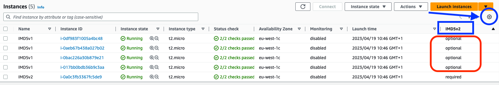
Figure 1: Example of IMDS versions for EC2 instances in the console
Using the AWS CLI
You can identify IMDSv1-enabled instances using the AWS Command Line Interface (AWS CLI) by running the aws ec2 describe-instances command and checking the value of HttpTokens. The HttpTokens value determines what version of IMDS is enabled, with optional enabling IMDSv1 and IMDSv2 and required means IMDSv2 is required. Similar to using the console, the optional status indicates that IMDSv1 is enabled on the instance and required indicates that IMDSv1 is disabled.
Using AWS Config
AWS Config continually assesses, audits, and evaluates the configurations and relationships of your resources on AWS, on premises, and on other clouds. The AWS Config rule ec2-imdsv2-check checks whether your Amazon EC2 instance metadata version is configured with IMDSv2. The rule is NON_COMPLIANT if the HttpTokens is set to optional, which means the EC2 instance has IMDSv1 enabled.
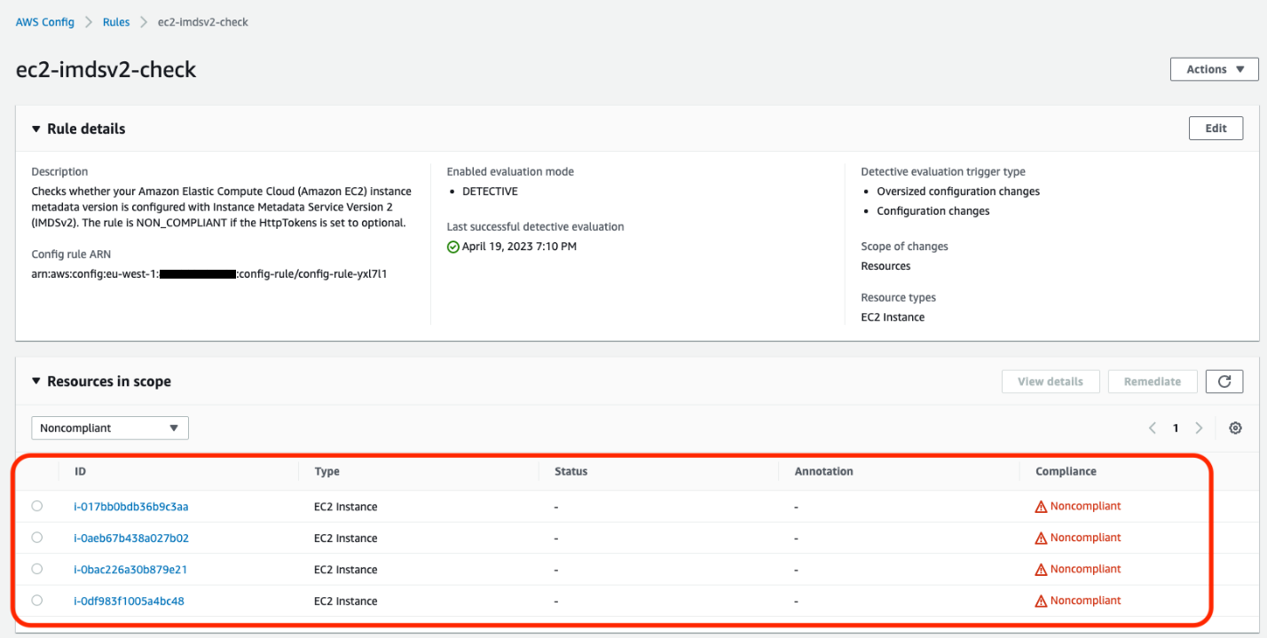
Figure 2: Example of noncompliant EC2 instances in the AWS Config console
After this AWS Config rule is enabled, you can set up AWS Config notifications through Amazon Simple notification Service (Amazon SNS).
Using Security Hub
AWS Security Hub provides detection and alerting capability at the account and organization levels. You can configure cross-Region aggregation in Security Hub to gain insight on findings across Regions. If using AWS Organizations, you can configure a Security Hub designated account to aggregate findings across accounts in your organization.
Security Hub has an Amazon EC2 control ([EC2.8] Amazon EC2 instances should use Instance Metadata Service Version 2 (IMDSv2)) that uses the AWS Config rule ec2-imdsv2-check to check if the instance metadata version is configured with IMDSv2. The rule is NON_COMPLIANT if the HttpTokens is set to optional, which means EC2 instance has IMDSv1 enabled.
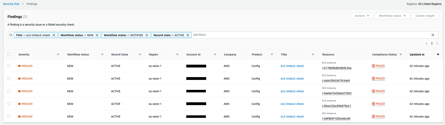
Figure 3: Example of AWS Security Hub showing noncompliant EC2 instances
Using Amazon Event Bridge, you can also set up alerting for the Security Hub findings when the EC2 instances are noncompliant for IMDSv2.
Identifying if EC2 instances are making IMDSv1 calls
Not all of your software will be making IMDSv1 calls; your dependent libraries and tools might already be compatible with IMDSv2. However, to mitigate against compatibility issues in requiring IMDSv2 and disabling IMDSv1 entirely, you must check for remaining IMDSv1 calls from your software. After you’ve identified that there are instances with IMDSv1 enabled, investigate if your software is making IMDSv1 calls. Most applications make IMDSv1 calls at instance launch and shutdown. For long running instances, we recommend monitoring IMDSv1 calls during a launch or a stop and restart cycle.
You can check whether your software is making IMDSv1 calls by checking the MetadataNoToken metric in Amazon CloudWatch. You can further identify the source of IMDSv1 calls by using the IMDS Packet Analyzer tool.
Steps to check IMDSv1 usage with CloudWatch
- Open the CloudWatch console.
- Go to Metrics and then All Metrics.
- Select EC2 and then choose Per-Instance Metrics.
- Search and add the Metric MetadataNoToken for the instances you’re interested in.
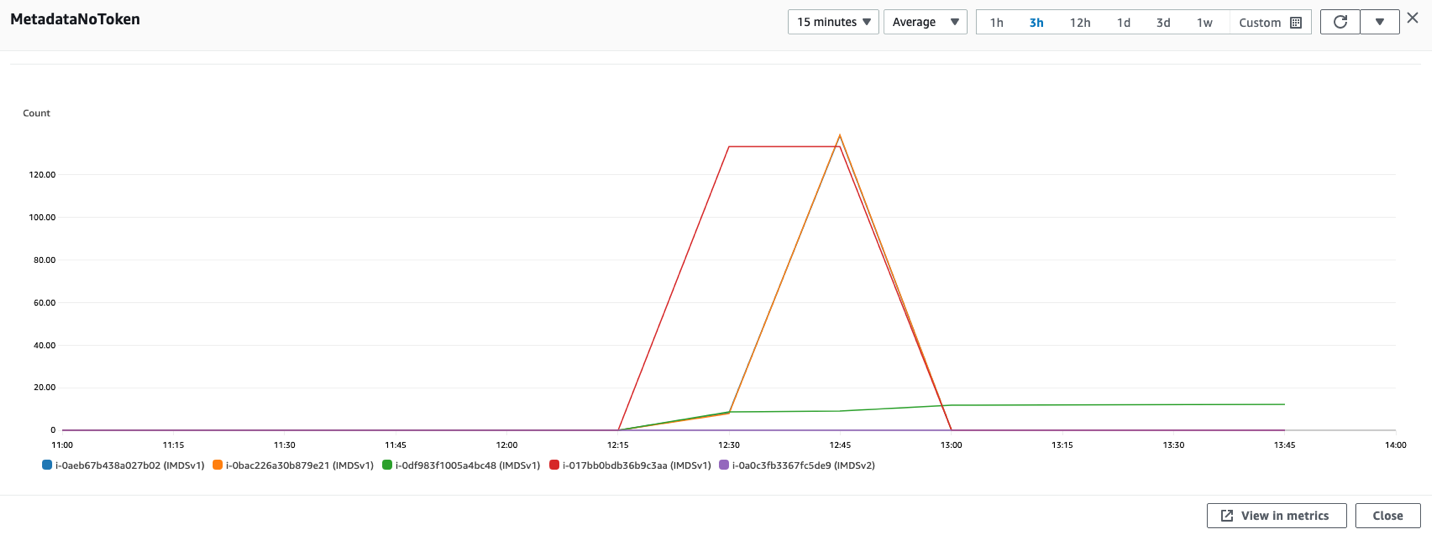
Figure 4: CloudWatch dashboard for MetadataNoToken per-instance metric
You can use expressions in CloudWatch to view account wide metrics.
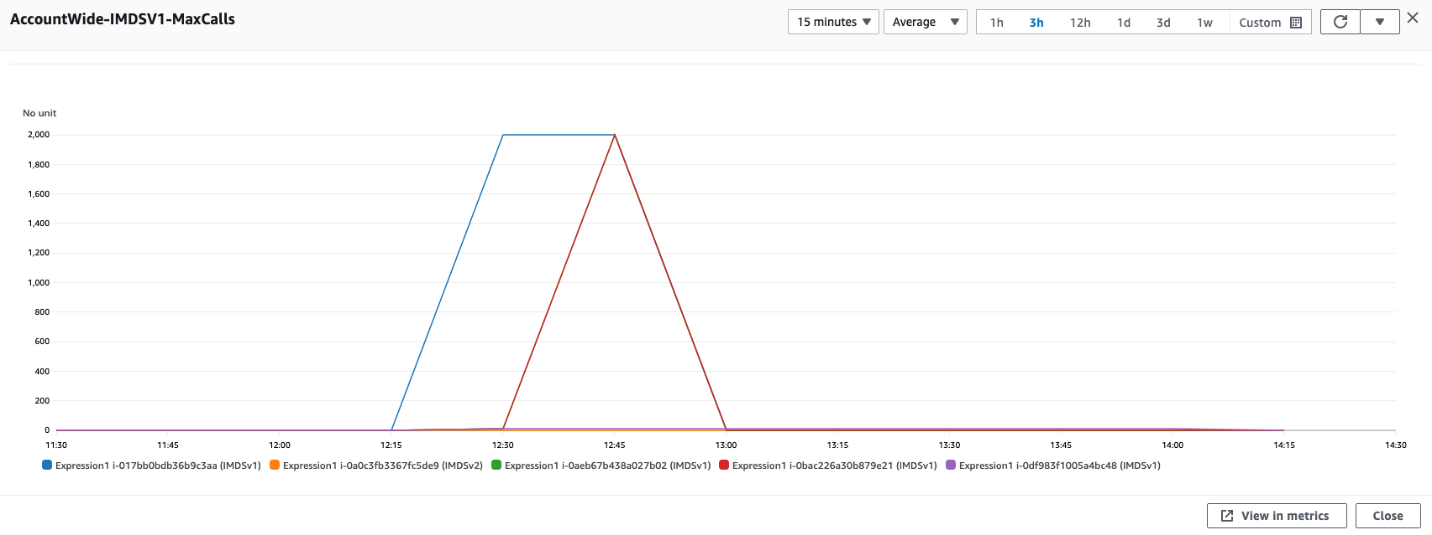
Figure 5: Using CloudWatch expressions to view account wide metrics for MetadataNoToken
You can combine SEARCH and SORT expressions in CloudWatch to help identify the instances using IMDSv1.
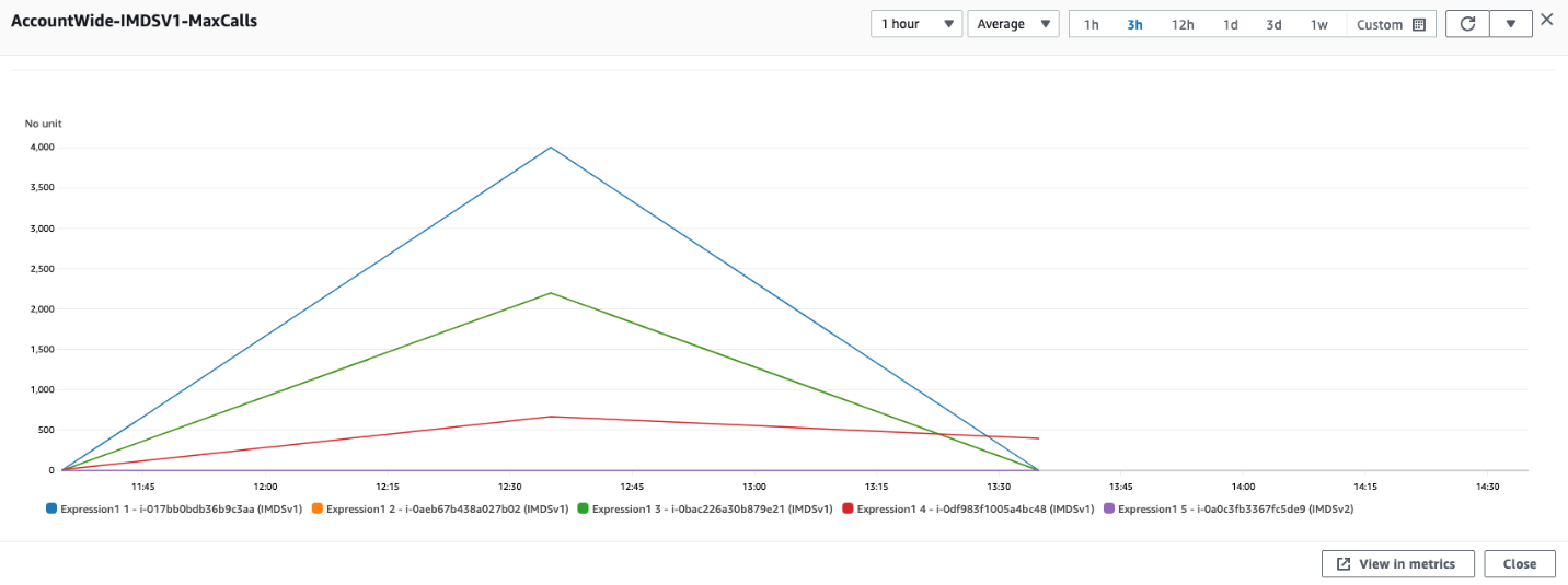
Figure 6: Another example of using CloudWatch expressions to view account wide metrics
If you have multiple AWS accounts or use AWS Organizations, you can set up a centralized monitoring account using CloudWatch cross account observability.
IMDS Packet Analyzer
The IMDS Packet Analyzer is an open source tool that identifies and logs IMDSv1 calls from your software, including software start-up on your instance. This tool can assist in identifying the software making IMDSv1 calls on EC2 instances, allowing you to pinpoint exactly what you need to update to get your software ready to use IMDSv2. You can run the IMDS Packet Analyzer from a command line or install it as a service. For more information, see IMDS Packet Analyzer on GitHub.
Disabling IMDSv1 and maintaining only IMDSv2 instances
After you’ve monitored and verified that the software on your EC2 instances isn’t making IMDSv1 calls, you can disable IMDSv1 on those instances. For all compatible workloads, we recommend using Amazon Linux 2023, which offers several improvements (see launch announcement), including requiring IMDSv2 (disabling IMDSv1) by default.
You can also create and modify AMIs and EC2 instances to disable IMDSv1. Configure the AMI provides guidance on how to register a new AMI or change an existing AMI by setting the imds-support parameter to v2.0. If you’re using container services (such as ECS or EKS), you might need a bigger hop limit to help avoid falling back to IMDSv1. You can use the modify-instance-metadata-options launch parameter to make the change. We recommend testing with a hop limit of three in container environments.
To create a new instance
For new instances, you can disable IMDSv1 and enable IMDSv2 by specifying the metadata-options parameter using the run-instance CLI command.
To modify the running instance
To configure a new AMI
To modify an existing AMI
Using the console
If you’re using the console to launch instances, after selecting Launch Instance from AWS Console, choose the Advanced details tab, scroll down to Metadata version and select V2 only (token required).
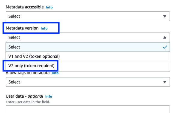
Figure 7: Modifying IMDS version using the console
Using EC2 launch templates
You can use an EC2 launch template as an instance configuration template that an Amazon Auto Scaling group can use to launch EC2 instances. When creating the launch template using the console, you can specify the Metadata version and select V2 only (token required).
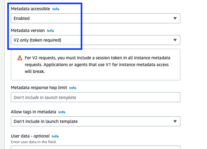
Figure 8: Modifying the IMDS version in the EC2 launch templates
Using CloudFormation with EC2 launch templates
When creating an EC2 launch template using AWS CloudFormation, you must specify the MetadataOptions property to use only IMDSv2 by setting HttpTokens as required.
In this state, retrieving the AWS Identity and Access Management (IAM) role credentials always returns IMDSv2 credentials; IMDSv1 credentials are not available.
Using Systems Manager automation runbook
You can run the EnforceEC2InstanceIMDSv2 automation document available in AWS Systems Manager, which will enforce IMDSv2 on the EC2 instance using the ModifyInstanceMetadataOptions API.
- Open the Systems Manager console, and then select Automation from the navigation pane.
- Choose Execute automation.
- On the Owned by Amazon tab, for Automation document, enter EnforceEC2InstanceIMDSv2, and then press Enter.
- Choose EnforceEC2InstanceIMDSv2 document, and then choose Next.
- For Execute automation document, choose Simple execution.
Note: If you need to run the automation on multiple targets, then choose Rate Control.
- For Input parameters, enter the ID of EC2 instance under InstanceId
- For AutomationAssumeRole, select a role.
Note: To change the target EC2 instance, the AutomationAssumeRole must have ec2:ModifyInstanceMetadataOptions and ec2:DescribeInstances permissions. For more information about creating the assume role for Systems Manager Automation, see Create a service role for Automation.
- Choose Execute.
Using the AWS CDK
If you use the AWS Cloud Development Kit (AWS CDK) to launch instances, you can use it to set the requireImdsv2 property to disable IMDSv1 and enable IMDSv2.
Using AWS SDK
The new clients for AWS SDK for Java 2.x use IMDSv2, and you can use the new clients to retrieve instance metadata for your EC2 instances. See Introducing a new client in the AWS SDK for Java 2.x for retrieving EC2 Instance Metadata for instructions.
Maintain only IMDSv2 EC2 instances
To maintain only IMDSv2 instances, you can implement service control policies and IAM policies that verify that users and software on your EC2 instances can only use instance metadata using IMDSv2. This policy specifies that RunInstance API calls require the EC2 instance use only IMDSv2. We recommend implementing this policy after all of the instances in associated accounts are free of IMDSv1 calls and you have migrated all of the instances to use only IMDSv2.
You can find more details on applicable service control policies (SCPs) and IAM policies in the EC2 User Guide.
Restricting credential usage using condition keys
As an additional layer of defence, you can restrict the use of your Amazon EC2 role credentials to work only when used in the EC2 instance to which they are issued. This control is complementary to IMDSv2 since both can work together. The AWS global condition context keys for EC2 credential control properties (aws:EC2InstanceSourceVPC and aws:EC2InstanceSourcePrivateIPv4) restrict the VPC endpoints and private IPs that can use your EC2 instance credentials, and you can use these keys in service control policies (SCPs) or IAM policies. Examples of these policies are in this blog post.
Conclusion
You won’t be able to get the full benefits of IMDSv2 until you disable IMDSv1. In this blog post, we showed you how to identify IMDSv1-enabled EC2 instances and how to determine if and when your software is making IMDSv1 calls. We also showed you how to disable IMDSv1 on new and existing EC2 infrastructure after your software is no longer making IMDSv1 calls. You can use these tools to transition your existing EC2 instances, and set your new EC2 launches, to use only IMDSv2.
If you have feedback about this post, submit comments in the Comments section below. If you have questions about this post, start a new thread on the AWS Compute re:Post or contact AWS Support.
Want more AWS Security news? Follow us on Twitter.


 Annie Nelson is a Senior Solutions Architect at AWS. She is a data enthusiast who enjoys problem solving and tackling complex architectural challenges with customers.
 Keerthi Chadalavada is a Senior Software Development Engineer at AWS Glue. She is passionate about designing and building end-to-end solutions to address customer data integration and analytic needs.
 Zach Mitchell is a Sr. Big Data Architect. He works within the product team to enhance understanding between product engineers and their customers while guiding customers through their journey to develop their enterprise data architecture on AWS.
 Gal Heyne is a Product Manager for AWS Glue with a strong focus on AI/ML, data engineering and BI. She is passionate about developing a deep understanding of customer’s business needs and collaborating with engineers to design easy to use data products.


 Shubham Purwar is a Cloud Engineer (ETL) at AWS Bengaluru specialized in AWS Glue and Amazon Athena. He is passionate about helping customers solve issues related to their ETL workload and implement scalable data processing and analytics pipelines on AWS. In his free time, Shubham loves to spend time with his family and travel around the world.
 Nitin Kumar is a Cloud Engineer (ETL) at AWS with a specialization in AWS Glue. He is dedicated to assisting customers in resolving issues related to their ETL workloads and creating scalable data processing and analytics pipelines on AWS.

 Philipp Klose is a Global Solutions Architect at AWS based in Munich. He works with enterprise FSI customers and helps them solve business problems by architecting serverless platforms. In this free time, Philipp spends time with his family and enjoys every geek hobby possible.
 Daniel Wessendorf is a Global Solutions Architect at AWS based in Munich. He works with enterprise FSI customers and is primarily specialized in machine learning and data architectures. In his free time, he enjoys swimming, hiking, skiing, and spending quality time with his family.
 Marvin Gersho is a Senior Solutions Architect at AWS based in New York City. He works with a wide range of startup customers. He previously worked for many years in engineering leadership and hands-on application development, and now focuses on helping customers architect secure and scalable workloads on AWS with a minimum of operational overhead. In his free time, Marvin enjoys cycling and strategy board games.
 Nathan Lichtenstein is a Senior Solutions Architect at AWS based in New York City. Primarily working with startups, he ensures his customers build smart on AWS, delivering creative solutions to their complex technical challenges. Nathan has worked in cloud and network architecture in the media, financial services, and retail spaces. Outside of work, he can often be found at a Broadway theater.


 Ziad WALI is an Acceleration Lab Solutions Architect at Amazon Web Services. He has over 10 years of experience in databases and data warehousing where he enjoys building reliable, scalable and efficient solutions. Outside of work, he enjoys sports and spending time in nature.


 Anand Komandooru is a Senior Cloud Architect at AWS. He joined AWS Professional Services organization in 2021 and helps customers build cloud-native applications on AWS cloud. He has over 20 years of experience building software and his favorite Amazon leadership principle is “
 Li Liu is a Senior Database Specialty Architect with the Professional Services team at Amazon Web Services. She helps customers migrate traditional on-premise databases to the AWS Cloud. She specializes in database design, architecture, and performance tuning.
 Neil Potter is a Senior Cloud Application Architect at AWS. He works with AWS customers to help them migrate their workloads to the AWS Cloud. He specializes in application modernization and cloud-native design and is based in New Jersey.
 Vivek Shrivastava is a Principal Data Architect, Data Lake in AWS Professional Services. He is a big data enthusiast and holds 14 AWS Certifications. He is passionate about helping customers build scalable and high-performance data analytics solutions in the cloud. In his spare time, he loves reading and finds areas for home automation.