Tag Archives: Architecture

How to Accelerate Performance and Availability of Multi-region Applications with Amazon S3 Multi-Region Access Points

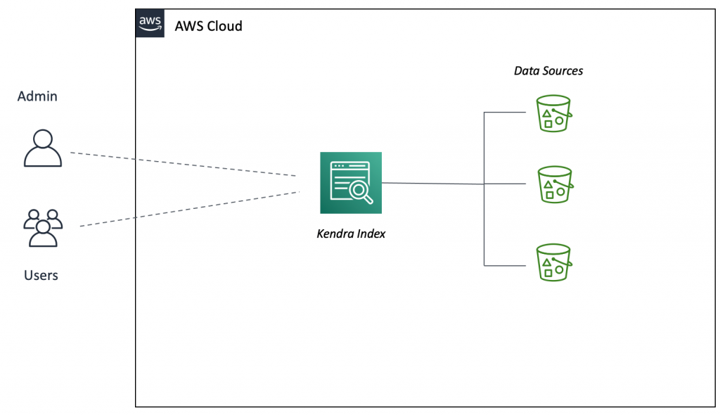
Post Syndicated from Alex Casalboni original https://aws.amazon.com/blogs/aws/s3-multi-region-access-points-accelerate-performance-availability/

Building multi-region applications allows you to improve latency for end users, achieve higher availability and resiliency in case of unexpected disasters, and adhere to business requirements related to data durability and data residency. For example, you might want to reduce the overall latency of dynamic API calls to your backend services . Or you might want to extend a single-region deployment to handle internet routing issues, failures of submarine cables, or regional connectivity issues – and therefore avoid costly downtime. Today, thanks to multi-region data replication functions such as Amazon DynamoDB global tables, Amazon Aurora global database, Amazon ElastiCache global datastore, and Amazon Simple Storage Service (Amazon S3) cross-region replication, you can build multi-region applications across 25 AWS Regions worldwide.

Yet, when it comes to implementing multi-region applications, you often have to make your code region-aware and take care of the heavy lifting of interacting with the correct regional resources, whether it’s the closest or the most available. For example, you might have three S3 buckets with object replication across three AWS Regions. Your application code needs to be aware of how many copies of the bucket exist and where they are located, which bucket is the closest to the caller, and how to fall back to other buckets in case of issues. The complexity grows when you add new regions to your multi-region architecture and redeploy your stack in each region whenever a global configuration changes.

Today, I’m happy to announce the general availability of Amazon S3 Multi-Region Access Points, a new S3 feature that allows you to define global endpoints that span buckets in multiple AWS Regions. With S3 Multi-Region Access Points, you can build multi-region applications with the same simple architecture used in a single region.

S3 Multi-Region Access Points deliver built-in network resilience, building on top AWS Global Accelerator to route S3 requests over the AWS global network. This is especially important to minimize network congestion and overall latency, while maintaining a simple application architecture. AWS Global Accelerator constantly monitors for regional availability and can shift requests to another region within seconds. By dynamically routing your requests to the lowest latency copy of your data, S3 Multi-Region Access Points increase upload and download performance by up to 60%. This is great not just for server-side applications that rely on S3 for reading configuration files or application data, but also for edge applications that need a performant and reliable write-only endpoint, such as IoT devices or autonomous vehicles.

S3 Multi-Region Access Points in Action
To get started, you create an S3 Multi-Region Access Point in the S3 console, via API, or with AWS CloudFormation.

Let me show you how to create one using the S3 console. Each access point needs a name, unique at the account level.

After it’s created, you can access it through its alias, which is generated automatically and globally unique. The alias will look like a random string ending with .mrap – for example, mmqdt41e4bf6x.mrap. It can also be accessed over the internet via https://mmqdt41e4bf6x.mrap.s3-global.amazonaws.com, via VPC, or on-premises using AWS PrivateLink.

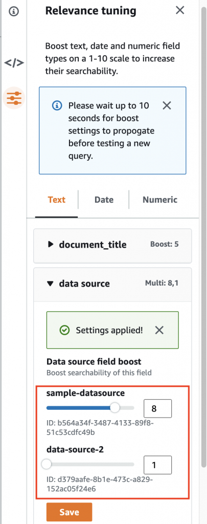
Then, you associate multiple buckets (new or existing) to the access point, one per Region. If you need data replication, you’ll need to enable bucket versioning too.

Finally, you configure the Block Public Access settings for the access point. By default, all public access is blocked, which works fine for most cases.

The creation process is asynchronous, you can view the creation status in the Console or by listing the S3 Multi-Region Access Points from the CLI. When it becomes Ready, you can configure optional settings for the access point policy and object replication.

Similar to regular access points, you can customize the access control policy to limit the use of the access point with respect to the bucket’s permission. Keep in mind that both the access point and the underlying buckets must permit a request. S3 Multi-Region Access Points cannot extend the permissions, just limit (or equal) them. You can also use IAM Access Analyzer to verify public and cross-account access for buckets that use S3 Multi-Region Access Points and preview access to your buckets before deploying permissions changes.

Your S3 Multi-Region Access Point access policy might look like this:

{
  "Version": "2012-10-17",
  "Statement": [
    {
      "Sid": "Default",
      "Effect": "Allow",
      "Principal": {
        "AWS": "YOUR_ACCOUNT_ID" 
      },
      "Action": ["s3:GetObject", "s3:PutObject"],
      "Resource": "arn:aws:s3::YOUR_ACCOUNT_ID:accesspoint/YOUR_ALIAS/object/*"
    }
   ]
}

To replicate data between buckets used with your S3 Multi-Region Access Point, you configure S3 Replication. In some cases, you might want to store different content in each bucket, or have a portion of a regional bucket for use with a global endpoint and other portions that aren’t replicated and used only with a regional access point or direct bucket access. For example, an IoT device configuration might include references to other regional API endpoints or regional resources that will be different for each bucket.

The new S3 console provides two basic templates that you can use to easily and centrally create replication rules:

  • Replicate objects from one or more source bucket to one or more destination buckets: This is ideal for ready-only use cases where data is always generated in a specific AWS Region and you want it to be available in all other Regions, too.
  • Replicate objects among all specified buckets: This is ideal for the IoT scenario I mentioned, where you’d define a write-only access point that devices use to upload data to the closest region, and you need this data to be available in all regions.

Of course, thanks to filters and conditions, you can create more sophisticated replication setups. For example, you might want to replicate only certain objects based on a prefix or tags.

Keep in mind that bucket versioning must be enabled for cross-region replication.

The console will take care of creating and configuring the replication rules and IAM roles. Note that to add or remove buckets, you would create a new the S3 Multi-Region Access Point with the revised list.

In addition to the replication rules, here is where you configure replication options such as Replication Time Control (RTC), replication metrics and notifications, and bidirectional sync. RTC allows you to replicate most new objects in seconds, and 99.99% of those objects within 15 minutes, for use cases where replication speed is important; replications metrics allow you to monitor how synchronized are your buckets in terms of object and byte count; bidirectional sync allows you to achieve an active-active configuration for put-heavy use cases in which object metadata needs to be replicated across buckets too.

After replication is configured, you get a very useful visual and interactive summary that allows you to verify which AWS Regions are enabled. You’ll see where they are on the map, the name of the regional buckets, and which replication rules are being applied.

After the S3 Multi-Region Access Point is defined and correctly configured, you can start interacting with it through the S3 API, AWS CLI, or the AWS SDKs. For example, this is how you’d write and read a new object using the CLI (don’t forget to upgrade to the latest CLI version):

# create a new object
aws s3api put-object --bucket arn:aws:s3::YOUR_ACCOUNT_ID:accesspoint/YOUR_ALIAS --key test.png --body test.png
# retrieve the same object
aws s3api get-object --bucket arn:aws:s3::YOUR_ACCOUNT_ID:accesspoint/YOUR_ALIAS --key test.png test.png

Last but not least, you can use bucket metrics in Amazon CloudWatch to keep track of how user requests are distributed across buckets in multiple AWS Regions.

CloudFormation Support at Launch
Today, you can start using two new CloudFormation resources to easily define an S3 Multi-Region Access Point: AWS::S3::MultiRegionAccessPoint and AWS::S3::MultiRegionAccessPointPolicy.

Here is an example:

Resources:
  MyS3MultiRegionAccessPoint:
    Type: AWS::S3::MultiRegionAccessPoint
    Properties:
      Regions:
        - Bucket: regional-bucket-ireland
        - Bucket: regional-bucket-australia
        - Bucket: regional-bucket-us-east
      PublicAccessBlockConfiguration:
        BlockPublicAcls: true
        IgnorePublicAcls: true
        BlockPublicPolicy: true
        RestrictPublicBuckets: true
  MyMultiRegionAccessPointPolicy:
    Type: AWS::S3::MultiRegionAccessPointPolicy
    Properties:
      MrapName: !Ref MyS3MultiRegionAccessPoint
      Policy:
        Version: 2012-10-17
        Statement:
          - Action: '*'
            Effect: Allow
            Resource: !Sub
              - 'arn:aws:s3::${AWS::AccountId}:accesspoint/${mrapalias}/object/*'
              - mrapalias: !GetAtt
                  - MyS3MultiRegionAccessPoint
                  - Alias
            Principal: {"AWS": !Ref "AWS::AccountId"}

The AWS::S3::MultiRegionAccessPoint resource depends only on the S3 bucket names. You don’t need to reference other regional stacks and you can easily centralize the S3 Multi-Region Access Point definition into its own stack. On the other hand, cross-region replication needs to be configured on each S3 bucket.

Cost considerations
When you use an S3 Multi-Region Access Point to route requests within the AWS global network, you pay a data routing cost of $0.0033 per GB processed, in addition to the standard charges for S3 requests, storage, data transfer, and replication. If your applications access the S3 Multi-Region Access Point over the internet, you’re also charged an internet acceleration cost per GB. This cost depends on the transfer type (upload or download) and whether the client and the bucket are in the same or different locations. For details, visit the S3 pricing page and select the data transfer tab.

Let me share a few practical examples:

  • All traffic within an AWS Region: In this simple case, your application runs in US East (N. Virginia) and you configure two S3 buckets in US East (N. Virginia) and US West (Oregon). The application uploads 100GB of data and the lowest latency bucket is in US East(N. Virginia). All the data is routed by your S3 Multi-Region Access Point in the same region and the total cost is $0.33.
  • All traffic across two AWS Regions: In this case, your application runs in US East (N. Virginia) and you configure two S3 buckets in US East (Ohio) and US West (Oregon). The application uploads 100GB of data and the lowest latency bucket is in US East (Ohio). All the data is routed by your S3 Multi-Region Access Point across two AWS Regions. The data routing cost for 100GB is the same of the previous example ($0.33), plus the S3 data transfer cost of $0.01 per GB, resulting in a total cost of $1.33.
  • All traffic over the internet across North America, Europe, and Asia Pacific (download and upload): In this case, your application runs on customer devices in North America, Europe, and Asia, and you configure two S3 buckets in US East (N. Virginia) and Europe (Ireland). One customer in North America uploads 50GB of data, which is routed to the bucket in US East (N. Virginia); a second customer in Europe downloads 50GB of data from the bucket in Europe (Ireland); a third customer in Asia downloads 50GB of data from the bucket in Europe (Ireland). The data routing cost for 150GB is $0.495. Plus the data transfer out from S3 to Europe of $0.09 per GB ($9), the internet acceleration cost from North America to the S3 bucket in US East (N. Virginia) of $0.0025 per GB ($0.125), the internet acceleration cost from the S3 bucket in Europe (Ireland) to Europe of $0.005 per GB ($0.25), and the internet acceleration cost from the S3 bucket in Europe (Ireland) to Asia of $0.05 per GB ($2.5). The total cost is $12.37. Please note that this example is intended to demonstrate how the internet acceleration cost works across continents. Also note that the internet acceleration cost to Asia might be reduced by an order of magnitude with an additional S3 bucket in Asia (see next example).
  • All the traffic over the internet across North America, Europe, and Asia Pacific (only upload): In this case, we consider the same conditions of the previous example. The only difference is that all customers only upload data and that you configure an additional bucket in Asia Pacific (Singapore). The data routing cost is the same ($0.495). Plus the internet acceleration cost from North America to the S3 bucket in US East (N. Virginia) of $0.0025 per GB ($0.125), the internet acceleration cost from Europe to the S3 bucket in Europe (Ireland) of $0.0025 per GB ($0.125), and the internet acceleration cost from Asia to the S3 bucket in Asia Pacific (Singapore) of $0.01 per GB ($0.5). The total cost is $1.24.

In other words, the routing cost is easy to estimate and doesn’t depend on the application type or data access pattern. The internet acceleration cost depends on the access pattern (downloads are more expensive than uploads) and on the client location with respect to the closest AWS Region. For global applications that upload or download data over the internet, you can minimize the internet acceleration cost by configuring at least one S3 bucket in each continent.

Available Today
Amazon S3 Multi-Region Access Points allow you to increase resiliency and accelerate application performance up to 60% when accessing data across multiple AWS Regions. We look forward to feedback about your use cases so that we can iterate quickly and simplify how you design and implement multi-region applications.

You can get started using the S3 API, CLI, SDKs, AWS CloudFormation or the S3 Console. This new functionality is available in 17 AWS Regions worldwide (see the full list of supported AWS Regions).

Learn More

Watch this video to hear more about S3 Multi-Region Access Points and see a short demo.

Check out the technical documentation for S3 Multi-Region Access Points.

Alex

Visualize AWS Security Hub Findings using Analytics and Business Intelligence Tools

Post Syndicated from Sujatha Kuppuraju original https://aws.amazon.com/blogs/architecture/visualize-aws-security-hub-findings-using-analytics-and-business-intelligence-tools/

To improve the security posture in your organization, you first must have a comprehensive view of your security, operations, and compliance data. AWS Security Hub gives you a thorough view of your security alerts and security posture across all your AWS accounts. This is shown as Security Hub findings, which are generated from different AWS services and partner products. Security Hub also provides the capability to filter, aggregate, and visualize these findings as Security Hub insights.

Organizations have additional requirements to centralize the Security Hub findings into their existing operational store. They also must connect the findings with other operational data. In this blog, we share two architecture design options, which collect Security Hub findings across Regions. You can make these findings searchable, and build multiple visualization dashboards using analytics and BI Tools in order to gain insights.

Some of the benefits of these architectures:

  • Ability to combine Security Hub findings across Regions and generate a single dashboard view
  • Ability to combine the various security and compliance data into a single centralized dashboard
  • Ability to correlate security and compliance findings with operational data. This can be AWS CloudTrail logs and customer logs for deeper analysis and insights
  • Ability to build a security and compliance scorecard across various dimensions. This is achieved by combining the Security Hub findings and AWS resource inventory generated using an enterprise-wide tagging strategy

Approach to visualize Security Hub findings in multi-account environments

There are four steps involved in this approach, as shown in Figure 1:

Figure 1. Steps involved in improving the visibility of AWS Security Hub findings

Figure 1. Steps involved in improving the visibility of AWS Security Hub findings

  1. Set up your AWS Security Hub administrator account. Designate one of the AWS accounts within your AWS Organizations to be a delegated administrator for Security Hub. This account can manage and receive and findings across member accounts.
  2. Enable AWS Security Hub in member accounts. Enable required security standards, AWS native service integration, and partner integrations in all the member accounts across your AWS Regions.
  3. Export and consolidate findings. For each Region you operate in, collect findings and consolidate across Regions by ingesting the findings to a centralized repository.
  4. Query and visualize insights. Query the findings from the centralized findings repository and build dashboards for visualizations.

Design option one: View Security Hub findings using AWS serverless analytics services

This option, shown in Figure 2, uses Amazon Athena, a serverless, interactive, query service that analyzes data in Amazon Simple Storage Service (S3) using standard SQL. AWS Glue, a serverless, data integration service discovers, prepares, and combines data for analytics, machine learning (ML), and application development is also used. Amazon QuickSight, a scalable, serverless, embeddable, ML-powered, business intelligence (BI) service is used to search and visualize Security Hub findings from multiple accounts and Regions.

Figure 2. Architecture to view Security Hub findings using AWS serverless analytics services

Figure 2. Architecture to view Security Hub findings using AWS serverless analytics services

Architecture overview

  • Designate an AWS account in your AWS Organization as a delegated administrator for Security Hub. This account will publish events to Amazon EventBridge for its own findings, in addition to findings received from member accounts.
  • Configure the EventBridge rule to deliver the Security Hub finding event type into Amazon Kinesis Data Firehose. If you are operating in multiple Regions set up an EventBridge rule and Kinesis Data Firehose in each of those Regions.
  • Set up Kinesis Data Firehose in multiple Regions to deliver data into a Single S3 bucket, which helps to consolidate findings across multiple Regions.
  • Partition the data in your S3-based by account number, Region, date, and other preferred parameters.
  • Use AWS Glue to crawl the S3 bucket and build the schema of the Security Hub findings. This is used by Amazon Athena to query the data. You can create a view in Athena to flatten some of the nested attributes in the Security Hub findings.
  • Build your Amazon QuickSight dashboard using the view created in Athena.

Figure 3 shows a sample dashboard created in QuickSight to view consolidated Security Hub findings across accounts and Regions.

Figure 3. Sample Security Hub findings dashboard created using Amazon QuickSight

Figure 3. Sample Security Hub findings dashboard created using Amazon QuickSight

Design option two: View Security Hub findings using a managed Amazon ES cluster and Kibana

This option, shown in Figure 4, uses a managed Amazon Elasticsearch Service cluster to ingest the findings, and Kibana to search and visualize the findings. Amazon Elasticsearch Service is a fully managed service that allows you to deploy, secure, and run Elasticsearch cost-effectively, and at scale.

Figure 4. Architecture to view Security Hub findings using Amazon ES cluster and Kibana

Figure 4. Architecture to view Security Hub findings using Amazon ES cluster and Kibana

Architecture overview

  • Similar to the previous design option, the Security Hub administrator account publishes events to Amazon EventBridge for findings.
  • Configure the EventBridge rule to deliver the Security Hub finding event type into Amazon Kinesis Data Firehose. If you are operating in multiple Regions, then you must set up an EventBridge rule and Kinesis Data Firehose in each of those Regions.
  • It’s recommended that you set up Kinesis Data Firehose in multiple Regions to deliver data into a central Amazon ES cluster. This serves as a single pane of glass for security findings across these different Regions.
  • Use Kibana, a popular open source visualization tool designed to work with Elasticsearch. You’ll be able to create visualizations and dashboards to analyze and share your findings.

Amazon ES can help you configure rules on the findings to send specialized alerts. When coupled with anomaly detection, Amazon ES can automatically detect anomalies in your findings data using unsupervised machine learning algorithm and alert you in near-real.

Figure 5 shows a sample dashboard created in Kibana to view consolidated Security Hub findings across accounts and Regions in an Elasticsearch cluster.

Figure 5. Sample Security Hub findings dashboard created in Kibana

Figure 5. Sample Security Hub findings dashboard created in Kibana

Conclusion

In this post, we showed you two architectural design options to collect AWS Security Hub findings across multiple AWS Regions in a multi-account AWS environment. These approaches allow you to connect the AWS Security Hub findings with other operational data. This makes it searchable, and will allow you to draw insights and achieve an improved organization-wide security posture. These options use AWS managed and serverless services, which are scalable and configurable for high availability and performance. Make your design choice based on your enterprise needs for search, analytics, and insights visualization options.

Further Reading:

Field Notes: How to Deploy End-to-End CI/CD in the China Regions Using AWS CodePipeline

Post Syndicated from Ashutosh Pateriya original https://aws.amazon.com/blogs/architecture/field-notes-how-to-deploy-end-to-end-ci-cd-in-the-china-regions-using-aws-codepipeline/

This post was co-authored by Ravi Intodia, Cloud Archiect, Infosys Technologies Ltd, Nirmal Tomar, Principal Consultant, Infosys Technologies Ltd and Ashutosh Pateriya, Solution Architect, AWS.

Today’s businesses must contend with fast-changing competitive environments, expanding security needs, and scalability issues. Businesses must find a way to reconcile the need for operational stability with the need for quick product development. Continuous integration and continuous delivery (CI/CD) enables rapid software iterations while maintaining system stability and security.

With an increase in AWS Cloud and DevOps adoption, many organizations seek solutions which go beyond geographical boundaries. AWS CodePipeline, along with its related services, lets you integrate and deploy your solutions across multiple AWS accounts and Regions. However, it becomes more challenging when you want to deploy your application in multiple AWS Regions as well as in China, due to the unavailability of AWS CodePipeline in the Beijing and Ningxia Regions.

In this blog post, you will learn how to overcome the unique challenges when deploying applications across many parts of the world, including China. For this solution, we will use the power and flexibility of AWS CodeBuild to implement AWS Command Line Interface (AWS CLI) commands to perform custom actions that are not directly supported by CodePipeline or AWS CodeDeploy.

CodePipeline for multi-account and multi-Region deployment consists of the following components:

  • ArtifactStore and encryption keys – In the AWS account which hosts CodePipeline, there should be an Amazon Simple Storage Service (Amazon S3) bucket and an AWS Key Management Service (AWS KMS) key for each Region where resources need to be deployed.
  • CodeBuild and CodePipeline roles – In the AWS account which hosts CodePipeline there should be roles created that can be used or assumed by CodeBuild and CodePipeline projects for performing required actions.
  • Cross-account roles – In each AWS account where cross-account deployments are required, an AWS role with the necessary permissions must be created. The CodePipeline role of the deploying account must be allowed to assume this role for all required accounts. Cross-account roles will also have access to the required S3 buckets and AWS KMS keys for deploying accounts.
Figure 1. High-level solution for AWS Regions

Figure 1. High-level solution for AWS Regions

Although the solution works for most Regions, we encounter challenges when we try to expand our current worldwide solutions into the China Regions.

The challenges are as follows:

  • Cross-account roles – Cross-account roles cannot be created between accounts in non-China Regions and the China Regions. This means that CodeDeploy will be unable to assume the target account role necessary to complete component deployment.
  • Availability of services – Services required to configure a cloud native CI/CD pipeline are unavailable in the China Regions.
  • Connectivity – There is no direct network connectivity available between the China Regions and other AWS Regions.
  • User management – Accounts by users in China are distinct from AWS Region user accounts, and must be maintained independently.

Due to the lack of cross-account roles and the CodePipeline service, setting up a worldwide CI/CD pipeline that includes the China Regions is not automatically supported.

High-level solution

In the proposed solution, we will build and deploy the application to both Regions using the AWS CI/CD services from the non-China Region, and we will create an access key in a China Region with access to deploy the application using services, such as AWS Lambda, AWS Elastic Beanstalk, Amazon Elastic Container Service, and Amazon Elastic Kubernetes Service. This access key is stored in a non-China account as an SSM parameter after encryption. On committing, the CodePipeline in the non-China Region is initiated, and it builds the package and deploys the application in both Regions from a single place.

Solution architecture

Figure 2. High-level solution for cross-account deployment from AWS Regions to a China Region

Figure 2. High-level solution for cross-account deployment from AWS Regions to a China Region

In this architecture, AWS CLI commands are used to set an AWS profile of CodeBuild instance with China credentials (retrieved from the AWS Systems Manager Parameter Store). This enables a CodeBuild instance to run an AWS CloudFormation package and deploy commands directly on the China account, thereby deploying required resources in the desired China Region.

This solution is not relying on any AWS CI/CD services like CodeDeploy in the China Region. With this solution we can create a complete CI/CD pipeline running in an AWS Region that can deploy an application in both Regions.

The following key components are needed for deployment:

  • AWS Identity and Access Management (IAM) user credentials – An IAM user needs to be created in the target account in China.
  • SSM parameter (secure string) – China IAM user access key (secret access key needs to be saved as a secure string SSM parameter in the deployment AWS account).
  • Update CloudFormation templates – CloudFormation templates need to be updated to support China Region mappings (such as using “arn:aws-cn” instead of “arn:aws”).
  • Enhance CodeBuild to support build and deployment – CodeBuild buildspec.yml needs to be enhanced to perform build and deployment to China accounts, as mentioned in the following.

Prerequisites

  • Two AWS accounts: One AWS account outside of China, and one account in China.
  • Practical experience in deploying Lambda functions using CodeBuild, CodeDeploy, and CodePipeline, and using AWS CLI. Because this example focuses specifically on extending CodePipeline from Regions outside of China to deploy in China Region, we are not going to explore a standard CodePipeline set up.

Detailed Implementation

This solution is built using CodePipeline, CodeCommit, CodeBuild, AWS Cloud​Formation templates, and IAM.

Steps

  1. One-time key generation in an account in China with necessary access to deploy application, including creation of one S3 bucket for CodeBuild artifacts.
    Note: As a best practice, we suggest rotation of the access key every 30 days.
  2. Complete the setup of CodePipeline to deploy application in Regions outside of China, as well as including China Region.

As a demonstration, let’s deploy a Lambda function in us-east-1 and cn-north-1 and discuss the steps in detail. The same steps can be followed to deploy any other AWS service.

Part 1 – In the account based in China Region: cn-north-1

  1. Create an S3 bucket with default encryption enabled for CodeBuild artifacts.

  1. Create an IAM user (with programmatic access only) with the required permissions to deploy Lambda functions and related resources. The IAM user will also have access to the S3 bucket created for CodeBuild artifacts.To create an IAM policy, refer to the AWS IAM Policy resource.

Part 2 – In AWS account based in non-China Region: us-east-1

  1. Create two SSM parameters of type secure string.
SSM Parameter Name SSM Parameter Value
/China/Dev/UserAccessKey <Value of China IAM User Access Key>

To create secure SSM parameters using the AWS CLI, refer to the Create a Systems Manager parameter (AWS CLI) tutorial.

To create secure SSM parameters using the AWS Management Console, refer to the Create a Systems Manager parameter (console) tutorial.

Note: Creating secure SSM parameters is not supported by CloudFormation templates. Also, as a security best practice, you should not have any sensitive information as part of CloudFormation templates to avoid any possible security breach.

  1. Create an AWS KMS key for encrypting CodeBuild or CodePipeline artifacts (for cross-Region deployments, create AWS KMS key in all Regions, and create SSM parameters for each in the Region having CodePipeline).
  2. Create artifacts S3 bucket for CodeBuild or CodePipeline artifacts.
  3. Create CI/CD related roles. For CI/CD service roles, refer to:
    https://docs.aws.amazon.com/codepipeline/latest/userguide/pipelines-create-service-role.html
    https://docs.aws.amazon.com/codebuild/latest/userguide/setting-up.html#setting-up-service-role
  4. Create a CodeCommit repository.
  5. Create SSM parameters for the following.
SSM Parameter Name SSM Parameter Value
/China/Dev/DeploymentS3Bucket <Artifact Bucket Name in China Region>
/US/Dev/CodeBuildRole <Role ARN of CodeBuild Service Role>
/US/Dev/CodePipelineRole <Role ARN of Codepipeline Service Role>
/US/Dev/CloudformationRole <Role ARN of Cloudformation Service Role>
/US/Dev/DeploymentS3Bucket <Artifact Bucket Name in Pipeline Region>
/US/Dev/CodeBuildImage <Code Build Image Details>
/US/Stage/CrossAccountStageRole <Role ARN for Cross Account Service Role for Stage>
/US/Prod/CrossAccountStageRole <Role ARN for Cross Account Service Role for Prod>
  1. In CodeCommit, push the Lambda code and CloudFormation template for deploying Lambda resources (Lambda function, Lambda role, Lambda log group, and so forth).
  2. In CodeCommit, push two buildspec yml files, one for us-east-1, and one for cn-north-1.
    1. buildspec.yml: For us-east-1
# Buildspec Reference Doc: https://docs.aws.amazon.com/codebuild/latest/userguide/build-spec-ref.html
version: 0.2
phases:
  install:
    runtime-versions:
      python: 3.7
  pre_build:
    commands:
      - echo "[+] Updating PIP...."
      - pip install --upgrade pip
      - echo "[+] Installing dependencies...."
      #- Commands To Install required dependencies
      - yum install zip unzip -y -q
      - pip install awscli --upgrade
      
  build:
    commands:
      - echo "Starting build `date` in `pwd`"
      - echo "Starting SAM packaging `date` in `pwd`"
      - aws cloudformation package --template-file cloudformation_template.yaml --s3-bucket ${S3_BUCKET} --output-template-file transform-packaged.yaml
      # Additional package commands for cross-region deployments
      - echo "SAM packaging completed on `date`"
      - echo "Build completed `date` in `pwd`"
     
artifacts:
  type: zip
  files:
    - transform-packaged.yaml
    # - additional artifacts for cross-region deployments 

  discard-paths: yes

cache:
  paths:
    - '/root/.cache/pip'
    1. buildspec-china.yml: For cn-north-1
      buildspec-china.yml will be customized for performing build and deployment both. Refer to the following for details.
# Buildspec Reference Doc: https://docs.aws.amazon.com/codebuild/latest/userguide/build-spec-ref.html
version: 0.2    
phases:
  install:
    runtime-versions:
      python: 3.7

  pre_build:
    commands:
      - echo "[+] Updating PIP...."
      - pip install --upgrade pip
      - echo "[+] Installing dependencies...."
      #- Commands To Install required dependencies
      - yum install zip unzip -y -q
      - pip install awscli --upgrade
      # Setting China Region IAM User Profile
      - echo "Start setting User Profile  `date` in `pwd`"
      - USER_ACCESS_KEY=`aws ssm get-parameter --name ${USER_ACCESS_KEY_SSM} --with-decryption --query Parameter.Value --output text`
      - USER_SECRET_KEY=`aws ssm get-parameter --name ${USER_SECRET_KEY_SSM} --with-decryption --query Parameter.Value --output text`
      - aws configure --profile china set aws_access_key_id ${USER_ACCESS_KEY}
      - aws configure --profile china set aws_secret_access_key ${USER_SECRET_KEY}
      - echo "Setting User Profile Completed `date` in `pwd`"

  build:
    commands:
      # Creating Deployment Package 
      - echo "Start build/packaging  `date` in `pwd`"
      - S3_BUCKET=`aws ssm get-parameter --name ${S3_BUCKET_SSM} --query Parameter.Value --output text`
      - zip -q -r package.zip *
      - >
        bash -c '
        aws cloudformation package 
        --template-file cloudformation_template_china.yaml
        --s3-bucket ${S3_BUCKET}
        --output-template-file transformed-template-china.yaml
        --profile china
        --region cn-north-1'
      - echo "Completed build/packaging  `date` in `pwd`"
  post_build:
    commands:
      # Deploying 
      - echo "Start deployment  `date` in `pwd`"
      - >
        bash -c '
        aws cloudformation deploy 
        --capabilities CAPABILITY_NAMED_IAM
        --template-file transformed-template-china.yaml
        --stack-name ${ProjectName}-app-stack-dev
        --profile china
        --region cn-north-1'
      - echo "Completed deployment  `date` in `pwd`"
artifacts:
  type: zip
  files:
    - package.zip
    - transformed-template-china.yaml

Environment Variables: USER_ACCESS_KEY_SSM, USER_SECRET_KEY_SSM and S3_BUCKET_SSM

After creating and committing the previous files, your CodeCommit repository will look like the following.

Now that we have a CodeCommit repository, next we will create a CodePipeline for Lambda with the following stages:

  1. Source – Use the previously created CodeCommit repository (CodeRepository-US-East-1) as the source.
  2. Build – The CodeBuild project uses buildspec.yml by default, and takes output of Source stage as input and builds artifacts for us-east-1.
  3. Deploy
    1. Code-Deploy Project for deploying to us-east-1
      This takes output of the previous CodeBuild stage as input and performs deployment in two steps: create-changeset and execute-changeset (assuming the required role attached to the Code-Deploy for deployment).
    2. CodeBuild Project for deploying to cn-north-1
      This takes output of Source stage as input and performs build and deployment both to cn-north-1 using buildspec-china.yml. Also, it uses China IAM user credentials and bucket SSM parameters from environment variables.CodeBuild project details are outlined in the following image.

  1. Optional – Add further steps like manual approval, deployment to higher environment, and so forth, as required.

Congratulations! you have just created a CodePipeline with Lambda deployed in both a non-China Region and a China Region. Your CodePipeline should appear similar to the following.

Figure 3. CodePipeline implementation for both regions

Figure 3. CodePipeline implementation for both Regions

Note: Actual CodePipeline view will be vertical only where all environment deployment will be one after the other. For the purpose of this example, we have placed them side-by-side to more easily showcase multiple environments.

CodePipeline Implementation Steps

We have created this pipeline with the following high-level steps, and you can add or remove steps as needed.

Step 1. After you commit the source code, CodePipeline will launch in the non-China Region and fetch the source code.

Step 2. Build the package using using buildspec.yml.

Step 3. Deploy the application in both Regions by following the subsection steps for development environment.

    1. Create the changeset for the development environment.
    2. Implement the changeset for the development environment.

Step 4. Repeat step 3, but deploy the application in the staging environment.

Step 5. Wait for approval from your administrator or application owner before deploying application in production environment.

Step 6. Repeat steps 3 and 4 to deploy the application in the production environment.

Cleaning up

To avoid incurring future charges, clean up the resources created as part of this blog post.

  • Delete the CloudFormation stack created in the non-China Region.
  • Delete the SSM parameter created to store the access key.
  • Delete the access created in the China Region.

Conclusion

In this blog post, we have explored the question: how can you use AWS services to implement CI/CD in a China Region and keep them in sync with an AWS Region? Although we are using us-east-1 as an example here, this solution will work for any Region where CodePipeline services are available, including the China Region.

The question has been answered by dividing it into three problem statements as follows.

Problem 1: CodePipeline is not available in the China Regions.
Solution: Set up CodePipeline in a non-China Region and deploy to a China Region.

Problem 2: AWS cross-account roles are not possible between a non-China Region and the China Regions.
Solution: Use the power and flexibility of CodeBuild to build your application and also deploy your application using the AWS CLI.

Problem 3: Keep a non-China Region and the China Regions in sync.
Solution: Maintain all code and managing deployments from a common deployment AWS account.

Reference:

AWS CodeCommit | Managed Source Control Service

AWS CodePipeline | Continuous Integration and Continuous Delivery

AWS CodeBuild – Fully Managed Build Service

Field Notes: How to Boost Your Search Results Using Relevance Tuning with Amazon Kendra

Post Syndicated from Sam Palani original https://aws.amazon.com/blogs/architecture/field-notes-how-to-boost-your-search-results-using-amazon-kendra-relevance-tuning/

One challenge enterprises face when they implement an intelligent search solution for their large data sources, is the ability to quickly provide relevant search results. When working with large data sources, not all features or attributes within your data will be equally relevant to all your users. We want to prioritize identifying and boosting specific attributes for your users to provide the most relevant search results.

Relevance in Amazon Kendra tuning allows you to give a boost to a result in the response when the query includes terms that match the attribute. For example, you might have two similar documents but one is created more recently. A good practice is to boost the relevance for the newer (or earlier) document.

Relevance tuning in Amazon Kendra can be performed manually at the Index level or at the query level. In this blog post, we show how to tune an existing index that is connected to external data sources, and ultimately optimize your internal search results.

Solution overview

We will walk through how you can manually tune your index using boosting techniques to achieve the best results. This enables you to prioritize the results from a specific data source so your users get the most relevant results when they perform searches.

Figure 1. Amazon Kendra setup

Figure 1 illustrates a standard Amazon Kendra setup. An Amazon Kendra index is connected to different Amazon Simple Storage Service (Amazon S3) buckets with multiple data sources.

There are two types of user personas. The first persona is administrators who are responsible for managing the index and performing administrative tasks such as access control, index tuning, and so forth. The second persona is users who access Amazon Kendra either directly or through a custom application that can make API search requests on an Amazon Kendra index. You can use relevance tuning to boost results from one of these data sources to provide a more relevant search result.

Prerequisites

This solution requires the following:

If you do not have these prerequisites set up, you might check out Create and query an index that walks you through how to create and query an index in Amazon Kendra.

Furthermore, the AWS services you use in this tutorial are within the AWS Free Tier under a 30-day trial.

Step 1 – Check facet definition

First, review your facet definition and confirm it is facetable, displayable, searchable, and sortable.

In the Amazon Kendra console, select your Amazon Kendra index, then select Facet definition in the Data management panel. Confirm that _data_source_id has all of its attributes checked.

Figure 2. Check facet definition

Step 2 – Review data sources

Next, verify that you have at least two data sources for your Amazon Kendra index.

In the Amazon Kendra console, select your Amazon Kendra index, and then select Data sources in the Data management panel. Confirm that your data sources are correctly synced and available. In our example, data-source-2 is an earlier version and contains unprocessed documents compared to sample-datasource that has newer versions and has more relevant content.

Figure 3. Verify data sources

Step 3 – Perform a regular Amazon Kendra search

Next, we will test a regular search without any relevance tuning. Select Search console, and enter the search term Amazon Kendra VPC. Review your search results.

Figure 4. Regular Amazon Kendra search

In our example search results, the document from the second data source 39_kendra-dg_kendra-dg appears as the third result.

Step 4 – Relevance tuning through boosting

Now we will boost the first data source so documents from the first data source are displayed ahead of the other data sources.

Select data source, and boost the first data source sample-datasource to 8. Press the Save button to save your tuning. Wait several seconds for the changes to propagate.

Figure 5. Boost sample-datasource

Step 5 – Perform the search after boosting

Next, we will test the search with relevance tuning applied. In the search text box enter the search term Amazon Kendra VPC. Review your search results.

Figure 6. Searching after boosting

Notice that the search result no longer contains the document from the second data source.

Cleaning up

To avoid incurring any future charges, remove any index created specifically for this tutorial. In the Amazon Kendra console, select your index. Then select Actions, and choose Delete.

Figure 7. Delete index

Conclusion

In this blog post, we showed you how relevance tuning can be used to produce results ranked by their relevance. We also walked you through an example regarding how to manually perform relevance tuning at the index level in Amazon Kendra to boost your search results.

In addition to relevance tuning at the index level, you can also perform relevance tuning at the query level. Finally, check out the What is Amazon Kendra? and Relevance tuning with Amazon Kendra blog posts to learn more.

Scaling Data Analytics Containers with Event-based Lambda Functions

Post Syndicated from Brian Maguire original https://aws.amazon.com/blogs/architecture/scaling-data-analytics-containers-with-event-based-lambda-functions/

The marketing industry collects and uses data from various stages of the customer journey. When they analyze this data, they establish metrics and develop actionable insights that are then used to invest in customers and generate revenue.

If you’re a data scientist or developer in the marketing industry, you likely often use containers for services like collecting and preparing data, developing machine learning models, and performing statistical analysis. Because the types and amount of marketing data collected are quickly increasing, you’ll need a solution to manage the scale, costs, and number of required data analytics integrations.

In this post, we provide a solution that can perform and scale with dynamic traffic and is cost optimized for on-demand consumption. It uses synchronous container-based data science applications that are deployed with asynchronous container-based architectures on AWS Lambda. This serverless architecture automates data analytics workflows utilizing event-based prompts.

Synchronous container applications

Data science applications are often deployed to dedicated container instances, and their requests are routed by an Amazon API Gateway or load balancer. Typically, an Amazon API Gateway routes HTTP requests as synchronous invocations to instance-based container hosts.

The target of the requests is a container-based application running a machine learning service (SciLearn). The service container is configured with the required dependency packages such as scikit-learn, pandas, NumPy, and SciPy.

Containers are commonly deployed on different targets such as on-premises, Amazon Elastic Container Service (Amazon ECS), Amazon Elastic Compute Cloud (Amazon EC2), and AWS Elastic Beanstalk. These services run synchronously and scale through Amazon Auto Scaling groups and a time-based consumption pricing model.

Figure 1. Synchronous container applications diagram

Figure 1. Synchronous container applications diagram

Challenges with synchronous architectures

When using a synchronous architecture, you will likely encounter some challenges related to scale, performance, and cost:

  • Operation blocking. The sender does not proceed until Lambda returns, and failure processing, such as retries, must be handled by the sender.
  • No native AWS service integrations. You cannot use several native integrations with other AWS services such as Amazon Simple Storage Service (Amazon S3), Amazon EventBridge, and Amazon Simple Queue Service (Amazon SQS).
  • Increased expense. A 24/7 environment can result in increased expenses if resources are idle, not sized appropriately, and cannot automatically scale.

The New for AWS Lambda – Container Image Support blog post offers a serverless, event-based architecture to address these challenges. This approach is explained in detail in the following section.

Benefits of using Lambda Container Image Support

In our solution, we refactored the synchronous SciLearn application that was deployed on instance-based hosts as an asynchronous event-based application running on Lambda. This solution includes the following benefits:

  • Easier dependency management with Dockerfile. Dockerfile allows you to install native operating system packages and language-compatible dependencies or use enterprise-ready container images.
  • Similar tooling. The asynchronous and synchronous solutions use Amazon Elastic Container Registry (Amazon ECR) to store application artifacts. Therefore, they have the same build and deployment pipeline tools to inspect Dockerfiles. This means your team will likely spend less time and effort learning how to use a new tool.
  • Performance and cost. Lambda provides sub-second autoscaling that’s aligned with demand. This results in higher availability, lower operational overhead, and cost efficiency.
  • Integrations. AWS provides more than 200 service integrations to deploy functions as container images on Lambda, without having to develop it yourself so it can be deployed faster.
  • Larger application artifact up to 10 GB. This includes larger application dependency support, giving you more room to host your files and packages in oppose to hard limit of 250 MB of unzipped files for deployment packages.

Scaling with asynchronous events

AWS offers two ways to asynchronously scale processing independently and automatically: Elastic Beanstalk worker environments and asynchronous invocation with Lambda. Both options offer the following:

  • They put events in an SQS queue.
  • They can be designed to take items from the queue only when they have the capacity available to process a task. This prevents them from becoming overwhelmed.
  • They offload tasks from one component of your application by sending them to a queue and process them asynchronously.

These asynchronous invocations add default, tunable failure processing and retry mechanisms through “on failure” and “on success” event destinations, as described in the following section.

Integrations with multiple destinations

“On failure” and “on success” events can be logged in an SQS queue, Amazon Simple Notification Service (Amazon SNS) topic, EventBridge event bus, or another Lambda function. All four are integrated with most AWS services.

“On failure” events are sent to an SQS dead-letter queue because they cannot be delivered to their destination queues. They will be reprocessed them as needed, and any problems with message processing will be isolated.

Figure 2 shows an asynchronous Amazon API Gateway that has placed an HTTP request as a message in an SQS queue, thus decoupling the components.

The messages within the SQS queue then prompt a Lambda function. This runs the machine learning service SciLearn container in Lambda for data analysis workflows, which are integrated with another SQS dead letter queue for failures processing.

Figure 2. Example asynchronous-based container applications diagram

Figure 2. Example asynchronous-based container applications diagram

When you deploy Lambda functions as container images, they benefit from the same operational simplicity, automatic scaling, high availability, and native integrations. This makes it an appealing architecture for our data analytics use cases.

Design considerations

The following can be considered when implementing Docker Container Images with Lambda:

  • Lambda supports container images that have manifest files that follow these formats:
    • Docker image manifest V2, schema 2 (Docker version 1.10 and newer)
    • Open Container Initiative (OCI) specifications (v1.0.0 and up)
  • Storage in Lambda:
  • On create/update, Lambda will cache the image to speed up the cold start of functions during execution. Cold starts occur on an initial request to Lambda, which can lead to longer startup times. The first request will maintain an instance of the function for only a short time period. If Lambda has not been called during that period, the next invocation will create a new instance
  • Fine grain role policies are highly recommended for security purposes
  • Container images can use the Lambda Extensions API to integrate monitoring, security and other tools with the Lambda execution environment.

Conclusion

We were able to architect this synchronous service based on a previously deployed on instance-based hosts and design it to become asynchronous on Amazon Lambda.

By using the new support for container-based images in Lambda and converting our workload into an asynchronous event-based architecture, we were able to overcome these challenges:

  • Performance and security. With batch requests, you can scale asynchronous workloads and handle failure records using SQS Dead Letter Queues and Lambda destinations. Using Lambda to integrate with other services (such as EventBridge and SQS) and using Lambda roles simplifies maintaining a granular permission structure. When Lambda uses an Amazon SQS queue as an event source, it can scale up to 60 more instances per minute, with a maximum of 1,000 concurrent invocations.
  • Cost optimization. Compute resources are a critical component of any application architecture. Overprovisioning computing resources and operating idle resources can lead to higher costs. Because Lambda is serverless, it only incurs costs on when you invoke a function and the resources allocated for each request.

Augmenting VMware Cloud on AWS Workloads with Native AWS services

Post Syndicated from Talha Kalim original https://aws.amazon.com/blogs/architecture/augmenting-vmware-cloud-on-aws-workloads-with-native-aws-services/

VMware Cloud on AWS allows you to quickly migrate VMware workloads to a VMware-managed Software-Defined Data Center (SDDC) running in the AWS Cloud and extend your on-premises data centers without replatforming or refactoring applications.

You can use native AWS services with Virtual Machines (VMs) in the SDDC, to reduce operational overhead and lower your Total Cost of Ownership (TCO) while increasing your workload’s agility and scalability.

This post covers patterns for connectivity between native AWS services and VMware workloads. We also explore common integrations, including using AWS Cloud storage from an SDDC, securing VM workloads using AWS networking services, and using AWS databases and analytics services with workloads running in the SDDC.

Networking between SDDC and native AWS services

Establishing robust network connectivity with VMware Cloud SDDC VMs is critical to successfully integrating AWS services. This section shows you different options to connect the VMware SDDC with your native AWS account.

The simplest way to get started is to use AWS services in the connected Amazon Virtual Private Cloud (VPC) that is selected during the SDDC deployment process. Figure 1 shows this connectivity, which is automatically configured and available once the SDDC is deployed.

Figure 1. SDDC to Customer Account VPC connectivity configured at deployment

Figure 1. SDDC to Customer Account VPC connectivity configured at deployment

The SDDC Elastic Network Interface (ENI) allows you to connect to native AWS services within the connected VPC, but it doesn’t provide transitive routing beyond the connected VPC. For example, it will not connect the SDDC to other VPCs and the internet.

If you’re looking to connect to native AWS services in multiple accounts and VPCs in the same AWS Region, you have two connectivity options. These are explained in the following sections.

Attaching VPCs to VMware Transit Connect

When you need high-throughput connectivity in a multi-VPC environment, use VMware Transit Connect (VTGW), as shown in Figure 2.

Figure 2. Multi-account VPC connectivity through VMware Transit Connect VPC attachments

Figure 2. Multi-account VPC connectivity through VMware Transit Connect VPC attachments

VTGW uses a VMware-managed AWS Transit Gateway to interconnect SDDCs within an SDDC group. It also allows you to attach your VPCs in the same Region to the VTGW by providing connectivity to any SDDC within the SDDC group.

Connecting through an AWS Transit Gateway

To connect to your VPCs through an existing Transit Gateway in your account, use IPsec virtual private network (VPN) connections from the SDDC with Border Gateway Protocol (BGP)-based routing, as shown in Figure 3. Multiple IPsec tunnels to the Transit Gateway use equal-cost multi-path routing, which increases bandwidth by load-balancing traffic.

Figure 3. Multi-account VPC connectivity through an AWS Transit Gateway

Figure 3. Multi-account VPC connectivity through an AWS Transit Gateway

For scalable, high throughput connectivity to an existing Transit Gateway, connect to the SDDC via a Transit VPC that is attached to the VTGW, as shown in Figure 3. You must manually configure the routes between the VPCs and SDDC for this architecture.

In the following sections, we’ll show you how to use some of these connectivity options for common native AWS services integrations with VMware SDDC workloads.

Reducing TCO with Amazon EFS, Amazon FSx, and Amazon S3

As you are sizing your VMware Cloud on AWS SDDC, consider using AWS Cloud storage for VMs that provide files services or require object storage. Migrating these workloads to cloud storage like Amazon Simple Storage Service (Amazon S3), Amazon Elastic File System (Amazon EFS), or Amazon FSx can reduce your overall TCO through optimized SDDC sizing.

Additionally, you can reduce the undifferentiated heavy lifting involved with deploying and managing complex architectures for file services in VM disks. Figure 4 shows how these services integrate with VMs in the SDDC.

Figure 4. Connectivity examples for AWS Cloud storage services

Figure 4. Connectivity examples for AWS Cloud storage services

We recommend connecting to your S3 buckets via the VPC gateway endpoint in the connected VPC. This is a more cost-effective approach because it avoids the data processing costs associated with a VTGW and AWS PrivateLink for Amazon S3.

Similarly, the recommended approach for Amazon EFS and Amazon FSx is to deploy the services in the connected VPC for VM access through the SDDC elastic network interface. You can also connect to existing Amazon EFS and Amazon FSx file shares in other accounts and VPCs using a VTGW, but consider the data transfer costs first.

Integrating AWS networking and content delivery services

Using various AWS networking and content delivery services with VMware Cloud on AWS workloads will provide robust traffic management, security, and fast content delivery. Figure 5 shows how AWS networking and content delivery services integrate with workloads running on VMs.

Figure 5. Connectivity examples for AWS networking and content delivery services

Figure 5. Connectivity examples for AWS networking and content delivery services

Deploy Elastic Load Balancing (ELB) services in a VPC subnet that has network reachability to the SDDC VMs. This includes the connected VPC over the SDDC elastic network interface, a VPC attached via VTGW, and VPCs attached to a Transit Gateway connected to the SDDC.

VTGW connectivity should be used when the design requires using existing networking services in other VPCs. For example, if you have a dedicated internet ingress/egress VPC. An internal ELB can also be used for load-balancing traffic between services running in SDDC VMs and services running within AWS VPCs.

Use Amazon CloudFront, a global content delivery service, to integrate with load balancers, S3 buckets for static content, or directly with publicly accessible SDDC VMs. Additionally, use Amazon Route 53 to provide public and private DNS services for VMware Cloud on AWS. Deploy services such as AWS WAF and AWS Shield to provide comprehensive network security for VMware workloads in the SDDC.

Integrating with AWS database and analytics services

Data is one the most valuable assets in an organization, and databases are often the most demanding and critical workloads running in on-premises VMware environments.

A common customer pattern to reduce TCO for storage-heavy or memory-intensive databases is to use purpose-built Databases on AWS like Amazon Relational Database Service (RDS). Amazon RDS lets you migrate on-premises relational databases to the cloud and integrate it with SDDC VMs. Using AWS databases also reduces operational overhead you may incur with tasks associated with managing availability, scalability, and disaster recovery (DR).

With AWS Analytics services integrations, you can take advantage of the close proximity of data within VMware Cloud on AWS data stores to gain meaningful insights from your business data. For example, you can use Amazon Redshift to create a data warehouse to run analytics at scale on relational data from transactional systems, operational databases, and line-of-business applications running within the SDDC.

Figure 6 shows integration options for AWS databases and analytics services with VMware Cloud on AWS VMs.

Figure 6. Connectivity examples for AWS Database and Analytics services

Figure 6. Connectivity examples for AWS Database and Analytics services

We recommend deploying and consuming database services in the connected VPC. If you have existing databases in other accounts or VPCs that require integration with VMware VMs, connect them using the VTGW.

Analytics services can involve ingesting large amounts of data from various sources, including from VMs within the SDDC, creating a significant amount of data traffic. In such scenarios, we recommend using the SDDC connected VPC to deploy any required interface endpoints for analytics services to achieve a cost-effective architecture.

Summary

VMware Cloud on AWS is one of the fastest ways to migrate on-premises VMware workloads to the cloud. In this blog post, we provided different architecture options for connecting the SDDC to native AWS services. This lets you evaluate your requirements to select the most cost-effective option for your workload.

The example integrations covered in this post are common AWS service integrations, including storage, network, and databases. They are a great starting point, but the possibilities are endless. Integrating services like Amazon Machine Learning (Amazon ML), and Serverless on AWS allows you to deliver innovative services to your users, often without having to re-factor existing application backends running on VMware Cloud on AWS.

Additional Resources

If you need to integrate VMware Cloud on AWS with an AWS service, explore the following resources and reach out to us at AWS.

Field Notes: Deploy and Visualize ROS Bag Data on AWS using rviz and Webviz for Autonomous Driving

Post Syndicated from Aubrey Oosthuizen original https://aws.amazon.com/blogs/architecture/field-notes-deploy-and-visualize-ros-bag-data-on-aws-using-rviz-and-webviz-for-autonomous-driving/

In the automotive industry, ROS bag files are frequently used to capture drive data from test vehicles configured with cameras, LIDAR, GPS, and other input devices. The data for each device is stored as a topic in the ROS bag file. Developers and engineers need to visualize and inspect the contents of ROS bag files to identify issues or replay the drive data.

There are a couple of challenges to be addressed by migrating the visualization workflow into Amazon Web Services (AWS):

  • Search, identify, and stream scenarios for ADAS engineers. Visualization tool should be ready instantly, load the data for a certain scenario over a search API, and show the first result through data streaming, to provide a good user experience.
  • Native integration with the tool chain. Many customers implement the Data Catalog, data storage, and search API in AWS native services. This visualization tool should be integrated into such a tool chain directly.

Overview of solutions

This blog post describes three solutions on how to deploy and visualize ROS bag data on AWS by using two popular visualization tools:

  • rviz is the standard open-source visualization tool used by the ROS community and has a large set of tools and plugin support.
  • Webviz is an open-source tool created by Cruise that provides modular and configurable browser-based visualization.

In the autonomous driving data lake reference architecture, both visualization tools are covered in the step 10: Provide an advanced analytics and visualization toolchain including search function for particular scenarios using AWS AppSync, Amazon QuickSight (KPI reporting and monitoring), and Webviz, rviz, or other tooling for visualization.

Prerequisites

Solution 1 – Visualize ROS bag files using rviz on AWS RoboMaker virtual desktops

AWS RoboMaker provides simulation and testing infrastructure for robotics as a managed service. This includes out of the box support for virtual desktops with ROS tooling preconfigured and installed. When you launch a virtual desktop, AWS RoboMaker launches the NICE DCV web browser client. This client provides access to your AWS Cloud9 desktop and streaming applications.

Launch rviz on AWS RoboMaker virtual desktop

Follow the guide on creating a new development environment to provision a new integrated development environment (IDE) and open it. After your AWS Cloud9 IDE is open, you can launch a new virtual desktop by pressing the Virtual Desktop button at the top center of the IDE, and selecting Launch Virtual Desktop. This might take a couple of seconds to open in a new browser tab.

After your virtual desktop is loaded, you can run rviz by opening the terminal and running the following commands:

$ source /opt/ros/melodic/setup.bash
$ roscore &
$ rosrun rviz rviz

Solution 2 – Visualize ROS bag files using rviz on EC2 and TigerVNC

Note: We strongly recommend using the AWS RoboMaker managed solution for provisioning virtual desktops for your visualization needs. In cases where this is not possible due to different Linux distributions or versions, this solution allows an alternative method for setting up a virtual desktop on EC2.

In this solution (source code) we use AWS Cloud Development Kit (AWS CDK) to deploy a new Ubuntu 18.04 AMI EC2 instance to your AWS account and preconfigure it with rviz, TigerVNC, and Ubuntu Desktop.


Figure 1. Architecture for solution 2 (visualize ROS bag files using rviz on EC2 and TigerVNC)

Open a shell terminal that has your AWS CLI configured. Run the following commands to clone the code and install the corresponding nodejs dependencies.

$ git clone https://github.com/aws-samples/aws-autonomous-driving-data-lake-ros-bag-visualization-using-rviz.git rviz-infra
$ cd rviz-infra
$ npm install

Note: Review the README to understand the project structure and commands.

Next, configure your project-specific settings, like your AWS Account, Region, VNC password, VPC to deploy the Amazon EC2 machine into, and EC2 instance type by running the bootstrap script:

$ npm run project-bootstrap

You will be prompted for various inputs to bootstrap the project, including the VNC password to use. Most of these input values will be stored into your cdk.json file, and the VNC password will be stored in the AWS Systems Manager Parameter Store, a capability of AWS Systems Manager.

Run the following command to deploy your stack into your AWS account.

$ cdk deploy

After the stack has been deployed, and the EC2 instance provisioned, its user-data script will initiate and install TigerVNC and the required ROS tooling.

To see the progress, let’s connect to the instance using SSH and then tail the bootstrapping log.

$ ./ssm.sh ssh
$ sudo su ubuntu
$ tail -f /var/log/cloud-init-output.log

It takes approximately 15 minutes for the user-data bootstrapping script to finish. When it finishes, you will see the message “rviz-setup bootstrapping completed. You can now log in via VNC”.

Open a new shell terminal in the project root and start a port forwarding session using SSM through the ssm helper script:

$ ./ssm.sh vnc

After you see the waiting for connections output, you can open your VNC viewer and connect to localhost:5901.

When prompted for a password, enter the one you used when previously running the bootstrapping script.

You now have access to your Ubuntu Desktop environment.

Running rviz

If you opted to install sample data, the Ford AV Sample Data has been downloaded and installed on the EC2 instance already. To visualize it in rviz, a few helper scripts have been created and can be run by opening a new terminal and initiating the following commands:

$ cd /home/ubuntu/catkin_ws
$ ./0-run-all.sh

This helper script will open and run rviz on the Ford sample data.

Figure 2. Ford AV Dataset visualized with rviz on Ubuntu Desktop

You should now be able to use this server to run and visualize your ROS bag files using rviz.

Solution 3 – Visualize ROS bag files using Webviz on Amazon Elastic Container Service (Amazon ECS)

The third solution (source code) uses AWS CDK to deploy Webviz as a container running on AWS Fargate, fronted by an Application Load Balancer (ALB). In addition, the Infrastructure as Code (IaC) can either create a new Amazon S3 bucket or import an existing one. The S3 bucket would have its cross-origin resource sharing (CORS) rules updated to allow streaming bag files from your ALB domain.

The bucket and ROS bag files won’t need to be made public since we will use presigned Amazon S3 URLs for authorizing the streaming of the files.

Finally, the AWS CDK code deploys an AWS Lambda function that can be invoked to generate a properly formatted Webviz streaming URL that contains the HTTP encoded and presigned URL for streaming your bag files directly in the browser.

Figure 3. Architecture for solution 3 (visualize ROS bag files using Webviz on Amazon ECS)

To clone the repository and install its dependencies.

$ git clone https://github.com/aws-samples/aws-autonomous-driving-data-lake-ros-bag-visualization-using-webviz.git webviz-infra
$ cd webviz-infra
$ npm install

Note: Review the project README to understand the different files, project structures, and commands.

Next, modify the cdk.json to specify your specific project configurations (for example, region, bucket name, and whether you wish to import an existing bucket or create a new one).

{
  "context": {
    ....
    "bucketName": "<bucket_name>", // [required] Name of bucket to use or create
    "bucketExists": true, // [required] Should create or update existing bucket
    "generateUrlFunctionName": "generate_ros_streaming_url", // [required] Name of lambda function
    "scenarioDB": { // [optional] Configuration of SceneDescription table
      "partitionKey": "bag_file",
      "sortKey": "scene_id",
      "region": "eu-west-1",
      "tableName": "SceneDescriptions"
    }
  }
}

To deploy the CDK stack into your AWS account run the following command.

$ cdk deploy

You can now access your Webviz instance by opening the URL value for the webvizserviceServiceURL output from the previous deploy command.

Figure 4. Example showing Webviz being served by our ALB

Custom layouts for Webviz can be imported through json configs. The solution contains an example config in the project root. This custom layout contains the topic configurations and window layouts specific to our ROS bag format and should be modified according to your ROS bag topics.

  1. Select Config → Import/Export Layout
  2. Copy and paste the contents of layout.json

Figure 5. Configuring custom layout for Webviz

Next, you need some ROS bag files to stream into your S3 bucket. If you configured AWS CDK to use an existing bucket, and the bucket already contains some ROS bag files, then you can skip the next step.

Upload ROS bag files

You can use the AWS CLI to copy a local bag file to the specified S3 bucket using the aws s3 cp command. You can also copy files between S3 buckets with the aws s3 cp command.

Generate streaming URL with helper script

The code repository contains a Python helper script in the project root to invoke your deployed Lambda function generate_ros_streaming_url locally with the correct payload.

To run the helper script, run the following command in your terminal:

$ python get_url.py \
--bucket-name <bucket_name> \
--key <ros_bag_key>

Response format: http://webviz-lb-<account>.<region>.elb.amazonaws.com?remote-bag-url=<presigned-url>

The response URL can be opened directly in your browser to visualize your targeted ROS bag file.

Generate a streaming URL through Lambda function in the AWS Console

You can generate a streaming URL by invoking your Lambda function generate_ros_streaming_url with the following example payload in the AWS console.

{
"key": "<ros_bag_key>",
"bucket": "<bucket_name>",
"seek_to": "<ros_timestamp>"
}

The seek_to value informs the Lambda function to add a parameter to jump to the specified ROS timestamp when generating the streaming URL.

Example output:

{
"statusCode": 200,
"body":
"{\"url\": \"http://webviz-lb-<domain>.<region>.elb.amazonaws.com?remote-bag-url=<PRESIGNED_ENCODED_URL>&seek-to=<ros_timestamp>\"}"
}

This body output URL can be opened in your browser to start visualizing your bag files directly.

By using a Lambda function to generate the streaming URL, you have the flexibility to integrate it with other user interfaces or dashboards. For example, if you use Amazon QuickSight to visualize different detected scenarios, you can define a customer action to invoke the Lambda function through API Gateway to get a streaming URL for the target scenario.

Similarly, custom web applications can be used to visualize the scenes and their corresponding ROS bag files stored in a metadata store. Invoke the Lambda function from your web server to generate and return a visualization URL that can be use by the web application.

Using the streaming URL

Open the streaming URL in your browser. If you added a seek_to value while generating the URL, it should jump to that point in the bag file.

Figure 6. Example visualization of ROS bag file streamed from Amazon S3

That’s it. You should now start to see your ROS bag file being streamed directly from Amazon S3 in your browser.

Deploying Webviz as part of the Autonomous Driving Data Lake Reference Solution

This solution forms part of the autonomous driving data lake solution which consists of a reference architecture and corresponding field notes and open-source code modules:

  1. Building an automated scene detection pipeline for Autonomous Driving – ADAS Workflow
  2. Deploying Autonomous Driving and ADAS Workloads at Scale with Amazon Managed Workflows for Apache Airflow
  3. Building an Automated Image Processing and Model Training Pipeline for Autonomous Driving

If this Webviz solution is deployed in conjunction with Building an automated scene detection pipeline for Autonomous Driving – ADAS Workflow (ASD) it supports some out-of-the-box integration with solution 3.

You can configure the solution’s cdk.json to specify the relevant values for the SceneDescription table created by the ASD CDK code. Redeploy the stack after changing this using $ cdk deploy.

With these values, the Lambda function generate_ros_streaming_url now supports an additional payload format:

{
"record_id": “<scene_description_table_partition_key>”,
"scene_id": “<scene_description_table_sort_key>”
}

The get_url.py script also supports the additional scene lookup parameters. To look up a scene stored in your SceneDescription table run the following commands in your terminal:

$ python get_url.py –-record <scene_description_table_partition_key> --scene <scene_description_table_sort_key>

Invoking the generate_ros_streaming_url with the record and scene parameters will result in a lookup of the ROS bag file for the scene from DynamoDB, presigning the ROS bag file and returning an URL to stream the file directly in your browser.

Cleaning Up

To clean up the AWS RoboMaker development environment, review Deleting an Environment.

For the CDK application, you can destroy your CDK stack by running $ cdk destroy from your terminal. Some buckets will need to be manually emptied and deleted from the AWS console.

 Conclusion

This blog post illustrated how to deploy two common tools used to visualize ROS bag files, using three different solutions. First, we showed you how to set up an AWS RoboMaker development environment and run rviz. Second, we showed you how to deploy an Amazon EC2 machine that automatically configures Ubuntu-Desktop with TigerVNC and rviz preinstalled. Third, we showed you how to deploy Webviz on Fargate and configure a bucket to allow streaming bag files. Finally, you learned how streaming URLs can be generated and integrated into your custom scenario detection and visualization tools.

We hope you found this post interesting and helpful in extending your autonomous vehicle solutions, and invite your comments and feedback.

How IPONWEB Adopted Spot Instances to Run their Real-time Bidding Workloads

Post Syndicated from Roman Boiko original https://aws.amazon.com/blogs/architecture/how-iponweb-adopted-spot-instances-to-run-their-real-time-bidding-workloads/

IPONWEB is a global leader that builds programmatic, real-time advertising technology and infrastructure for some of the world’s biggest digital media buyers and sellers. The core of IPONWEB’s business is Real-time Bidding (RTB). IPONWEB’s platform processes, transmits, and auctions huge volumes of bid requests and bid responses in real time. They are then able to determine the optimal ad impression to be displayed to an end user.

IPONWEB processes over 1 trillion impression auctions per month. The volumes of impressions require significant compute power to make calculations and complete the entire bidding auction within 200 milliseconds. IPONWEB’s flagship RTB products, BidSwitch and BSWX, have been running on Amazon EC2 reserved and On-Demand Instances. The nature of the workload for this volume of compute for this short a time, has been notably spiky. IPONWEB maintained a core workload running 24/7 on EC2 instances covered by Reserved Instances and Savings Plans.

To optimize costs further, IPONWEB decided to use Amazon EC2 Spot Instances. Although this decision is also advantageous for workload efficiency, adopting Spot Instances did introduce a few challenges that needed to be addressed.

Some challenges in using Spot Instances for this use case

The Real-time Bidding (RTB) workload is critical to the business. Any interruption of bid processing has a negative impact on revenue. While the spikiness issue needed to be addressed, it was imperative to find a solution that could be implemented in a smooth and seamless fashion.

Efficient distribution over Availability Zones (AZs) within the AWS Region being used was imperative. RTB auctions process trillions of requests and consume large volumes of network traffic. Consequently, IPONWEB is continuously optimizing traffic costs along with compute costs. The architectural approach is to put as much workload as possible in one AZ to reduce inter-AZ traffic. For better performance, IPONWEB’s main MongoDB database and Spot Instances are running in the same AZ.

Under certain circumstances, using Spot Instances in other AZs can still be a good choice. AWS charges for traffic between AZs, so IPONWEB defined a break point. This occurs when usage of an EC2 Spot Instance in a different AZ became equal to usage of an EC2 On-Demand Instance in the same AZ.

This break point calculation led to the following best practices (in order of most value to least, for this use case):

  1. The most efficient practice was to run Spot Instances in the same AZ as the database
  2. Next effective was to run Spot Instances in the other AZs
  3. The third option was to run On-Demand Instances in the same AZ
  4. Least effective was to run On-Demand Instances in the other AZs

IPONWEB’s solution

IPONWEB evaluated Auto Scaling groups using both Spot and On-Demand Instances. They concluded that using Auto Scaling alone would not satisfy all the requirements, and it would be difficult to distribute workloads between AZs adequately. This is because an Auto Scaling group tries to distribute the instances across all the AZs evenly. However, IPONWEB needed to scale in one AZ initially, to avoid unnecessary cross AZ traffic. In addition, one Auto Scaling group can’t compensate for the sudden termination of a large number of Spot Instances. IPONWEB created a more flexible and reliable solution based on using four Auto Scaling groups.

  1. The first Auto Scaling group runs only on Spot Instances in the same AZ as the main database application.
  2. The second Auto Scaling group is running only Spot Instances in the other AZs.
  3. The third Auto Scaling group is running EC2 On-Demand Instances in the database AZ.
  4. The fourth Auto Scaling group is for EC2 On-Demand Instance on the other AZs.

The application workload running on the instances in these four Auto Scaling groups is evenly distributed. This is done using an Application Load Balancer (ALB), or IPONWEB’s purpose-built load balancer.

Figure 1. Spot and On-Demand scaling by different AZs

Figure 1. Spot and On-Demand Instances scaling by different AZs

IPONWEB then needed to create a proper scaling policy for each Auto Scaling group. They decided to implement a self-monitoring mechanism in the application. This monitored how much compute resources (CPU and memory) are still available at any given time. Using this information, the application determines if it is able to take the next processing request. If it’s unable to, a log entry is created, and an “empty” response is returned. IPONWEB created a composite metric based on the drop rate and CPU utilization of each host.

IPONWEB used that custom metric to create scaling policies for every Auto Scaling group. Each Auto Scaling group has a specific threshold. This provides granular control, such as when, and under what conditions the particular Auto Scaling group scales-out or scales-in. It will set a lower threshold for the first Auto Scaling group and higher thresholds for the next Auto Scaling groups.

For example, the group with Spot Instances in the same AZ starts scaling at 75% utilization. The group with Spot Instances in other AZs starts scaling at 80% utilization.

  • Because each instance in every group receives the same number of incoming requests to process, the first group will be scaling earlier than the others.
  • If some Spot Instances are shut down in the first group, then the total utilization will increase, and the second group will begin scaling.
  • If there is a shortage of Spot Instances in other AZs as well, then the group with EC2 On-Demand Instances will scale out.
  • When the Spot Instances are available and can be used again, the first group will use them. Then total utilization will decrease, causing the other groups to scale in.

Typically, the majority of this workload is done by the first group. The other groups are running with a bare minimum of two instances in each. After going live with this solution, IPONWEB observed that they can usually run the major portion of their workloads with the cheapest option. In this case, it was using Spot Instances in the same AZ as their database. There were several times when a large number of the Spot Instances were shut down. When this happened, the scaling diverted to On-Demand Instances. In general, the solution worked well and there was no degradation on the running services.

Conclusion

This solution helps IPONWEB utilize compute resources more efficiently using AWS, to place and process more bids. After the migration, IPONWEB increased infrastructure on AWS by ~15% without incurring additional costs. This solution can also be used for other workloads where you must have a granular control on the scaling while minimizing the costs.

Victor Gorelik, VP of Cloud Infrastructure at IPONWEB said:

“If you use cloud without optimizations, it is expensive. There are two ways to optimize the costs – use either Savings Plans or Spot Instances. But it feels like using Savings Plans is a step back to the traditional model where you buy hardware. On the other hand, using Spots is making you more Cloud native and is the way to move forward. I believe that in the future the majority of our workloads will be run on Spot.”

Read more here:

Field Notes: How to Scale OpenTravel Messaging Architecture with Amazon Kinesis Data Streams

Post Syndicated from Danny Gagne original https://aws.amazon.com/blogs/architecture/field-notes-how-to-scale-opentravel-messaging-architecture-with-amazon-kinesis-data-streams/

The travel industry relies on OpenTravel messaging systems to collect and distribute travel data—like hotel inventory and pricing—to many independent ecommerce travel sites. These travel sites need immediate access to the most current hotel inventory and pricing data. This allows shoppers access to the available rooms at the right prices. Each time a room is reserved, unreserved, or there is a price change, an ordered message with minimal latency must be sent from the hotel system to the travel site.

Overview of Solution

In this blog post, we will describe the architectural considerations needed to scale a low latency FIFO messaging system built with Amazon Kinesis Data Streams.

The architecture must satisfy the following constraints:

  1. Messages must arrive in order to each destination, with respect to their hotel code.
  2. Messages are delivered to multiple destinations independently.

Kinesis Data Streams is a managed service that enables real-time processing of streaming records. The service provides ordering of records, as well as the ability to read and replay records in the same order to multiple Amazon Kinesis applications. Kinesis data stream applications can also consume data in parallel from a stream through parallelization of consumers.

We will start with an architecture that supports one hotel with one destination, and scale it to support 1,000 hotels and 100 destinations (38,051 records per second). With the OpenTravel use case, the order of messages matters only within a stream of messages from a given hotel.

Smallest scale: One hotel with one processed delivery destination. One million messages a month.

Figure 1: Architecture showing a system sending messages from 1 hotel to 1 destination (.3805 RPS)

Figure 1: Architecture showing a system sending messages from 1 hotel to 1 destination (.3805 RPS)

Full Scale: 1,000 Hotels with 100 processed delivery destination. 100 billion messages a month.

Figure 2: Architecture showing a system sending messages from 1 hotel to 1 destination (38,051 RPS)

Figure 2: Architecture showing a system sending messages from 1 hotel to 1 destination (38,051 RPS)

In the example application, OpenTravel XML message data is the record payload. The record is written into the stream with a producer. The record is read from the stream shard by the consumer and sent to several HTTP destinations.

Each Kinesis data stream shard supports writes up to 1,000 records per second, up to a maximum data write total of 1 MB per second. Each shard supports reads up to five transactions per second, up to a maximum data read total of 2 MB per second. There is no upper quota on the number of streams you can have in an account.

Streams Shards Writes/Input limit Reads/Output limit
1 1 1 MB per second
1,000 records per second
2 MB per second
1 500 500 MB per second
500,000 records per second
1,000 MB per second

OpenTravel message

In the following OpenTravel message, there is only one field that is important to our use case: HotelCode. In OTA (OpenTravel Agency) messaging, order matters, but it only matters in the context of a given hotel, specified by the HotelCode. As we scale up our solution, we will use the HotelCode as a partition key. Each destination receives the same messages. If we are sending 100 destinations, then we will send the message 100 times. The average message size is 4 KB.

<HotelAvailNotif>
    <request>
        <POS>
            <Source>
                <RequestorID ID = "1000">
                </RequestorID>
                <BookingChannel>
                    <CompanyName Code = "ClientTravelAgency1">
                    </CompanyName>
                </BookingChannel>
            </Source>
        </POS>
   <AvailStatusMessages HotelCode="100">
     <AvailStatusMessage BookingLimit="9">
         <StatusApplicationControl Start="2013-12-20" End="2013-12-25" RatePlanCode="BAR" InvCode="APT" InvType="ROOM" Mon="true" Tue="true" Weds="true" Thur="false"  Fri="true" Sat="true" Sun="true"/>
         <LengthsOfStay ArrivalDateBased="true">
       <LengthOfStay Time="2" TimeUnit="Day" MinMaxMessageType="MinLOS"/>
       <LengthOfStay Time="8" TimeUnit="Day" MinMaxMessageType="MaxLOS"/>
         </LengthsOfStay>
         <RestrictionStatus Status="Open" SellThroughOpenIndicator="false" MinAdvancedBookingOffset="5"/>
     </AvailStatusMessage>    
    </AvailStatusMessages>
 </request>
</HotelAvailNotif>

Source: https://github.com/XML-Travelgate/xtg-content-articles-pub/blob/master/docs/hotel-push/HotelPUSH.md 

Producer and consumer message error handling

Asynchronous message processing presents challenges with error handling, because an error can be logged to the producer or consumer application logs. Short-lived errors can be resolved with a delayed retry. However, there are cases when the data is bad and the message will always cause an error; these messages should be added to a dead letter queue (DLQ).

Producer retries and consumer retries are some of reasons why records may be delivered more than once. Kinesis Data Streams does not automatically remove duplicate records. If the destination needs a strict guarantee of uniqueness, the message must have a primary key to remove duplicates when processed in the client (Handling Duplicate Records). In most cases, the destination can mitigate duplicate messages by processing the same message multiple times in a way that produces the same result (idempotence). If a destination endpoint becomes unavailable or is not performant, the consumer should back off and retry until the endpoint is available. The failure of a single destination endpoint should not impact the performance of delivery of messages to other destinations.

Messaging with one hotel and one destination

When starting at the smallest scale—one hotel and one destination—the system must support one million messages per month. This volume expects input of 4 GB of message data per month at a rate of 0.3805 records per second, and .0015 MB per second both input and output. For the system to process one hotel to one destination, it needs at least one producer, one stream, one shard, and a single consumer.

Hotels/Destinations Streams Shards Consumers (standard) Input Output
1 hotel, 1 destination
(4-KB average record size)
1 1 1 0.3805 records per second, or .0015 MB per second 0.3805 records per second, or .0015 MB per second
Maximum stream limits 1 1 1 250 (4-KB records) per second
1 MB per second (per stream)
500 (4-KB records) per second
2 MB per second (per stream)

With this design, the single shard supports writes up to 250 records per second, up to a maximum data write total of 1 MB per second. PutRecords request supports up to 500 records and each record in the request can be as large as 1 MB. Because the average message size is 4 KB, it enables 250 records per second to be written to the shard.

Figure 3: Architecture using Amazon Kinesis Data Streams (1 hotel, 1 destination)

The single shard can also support consumer reads up to five transactions per second, up to a maximum data read total of 2 MB per second. The producer writes to the shard in FIFO order. A consumer pulls from the shard and delivers to the destination in the same order as received. In this one hotel and one destination example, the consumer read capacity would be 500 records per second.

Figure 4: Records passing through the architecture

Messaging with 1,000 hotels and one destination

Next, we will maintain a single destination and scale the number of hotels from one hotel to 1,000 hotels. This scale increases the producer inputs from one million messages to one billion messages a month. This volume expects an input of 4 TB of message data per month at a rate of 380 records per second, and 1.486 MB per second.

Hotels/Destinations Streams Shards Consumers (standard) Input Output
1,000 hotels,
1 destination
(4-KB average
record size)
1 2 1 380 records per second, or
1.486 MB
per second
380 records per second, or
1.486 MB
per second
Maximum stream limits 1 2 1 500 (4-KB records) per second
2 MB per second
(per stream)
1,000 (4-KB records) per second
4 MB per second
(per stream)

The volume of incoming messages increased to 1.486 MB per second, requiring one additional shard. A shard can be split using the API to increase the overall throughput capacity. The write capacity is increased by distributing messages to the shards. We will use the HotelCode as a partition key, to maintain order of messages with respect to a given hotel. This will distribute the writes into the two shards. The messages for each HotelCode will be written into the same shard and maintain FIFO order. By using the HotelCode as a partition key, it doubles the stream write capacity to 2 MB per second.

A single consumer can read the records from each shard at 2 MB per second per shard. The consumer will iterate through each shard, processing the records in FIFO order based on the HotelCode. It then sends messages to the destination in the same order they were sent from the producer.

Messaging with 1,000 hotels and five destinations

As we scale up further, we maintain 1,000 hotels and scale the delivery to five destinations. This increases the consumer reads from one billion messages to five billion messages a month. It has the same input of 4 TB of message data per month at a rate of 380 records per second, and 1.486 MB per second. The output is now 326 GB of message data per month at a rate of 1,902.5 records per second, and 7.43 MB per second.

Hotels/Destinations Streams Shards Consumers (standard) Input Output
1,000 hotels,
5 destinations
(4-KB average
record size)
1 4 5 380 records per second, or 1.486 MB per second 1,902.5 records
per second, or
7.43 MB per second
Maximum stream capacity 1 4 5 1,000 (4-KB records) records per second
(per shard)
4 MB per second (per stream)
2,000 (4-KB records) records per second per shard with a
standard consumer
8 MB per second
(per stream)

To support this scale, we increase the number of consumers to match the destinations. A dedicated consumer for each destination allows the system to have committed capacity to each destination. If a destination fails or becomes slow, it will not impact other destination consumers.

Figure 5: Four Kinesis shards to support read throughput

We increase to four shards to support additional read throughput required for the increased destination consumers. Each destination consumer iterates through the messages in each shard in FIFO order based on the HotelCode. It then sends the messages to the assigned destination maintaining the hotel specific ordering. Like in the previous 1,000-to-1 design, the messages for each HotelCode are written into the same shard while maintaining its FIFO order.

The distribution of messages per HotelCode should be monitored with the metrics like WriteProvisionedThroughputExceeded and ReadProvisionedThroughputExceeded to ensure an even distribution between shards, because HotelCode is the partition key. If there is uneven distribution, it may require a dedicated shard for each HotelCode. In the following examples, it is assumed that there is an even distribution of messages.

Figure 6: Architecture showing 1,000 Hotels, 4 Shards, 5 Consumers, and 5 Destinations

Messaging with 1,000 hotels and 100 destinations

With 1,000 hotels and 100 destinations, the system processes 100 billion messages per month. It continues to have the same number of incoming messages, 4 TB of message data per month, at a rate of 380 records per second, and 1.486 MB per second. The number of destinations has increased from 4 to 100, resulting in 390 TB of message data per month, at a rate of 38,051 records per second, and 148.6 MB per second.

Hotels/Destinations Streams Shards Consumers (standard) Input Output
1,000 hotels,
100 destinations
(4-KB average
record size)
1 78 100 380 records per second, or
1.486 MB per second
38,051 records per second, or
148.6 MB per second
Maximum stream capacity 1 78 100 19,500 (4-KB records) records per second (per stream)
78 MB per second (per stream)
39,000 (4-KB records) records per second per stream with a standard consumer
156 MB per second
(per stream)

The number of shards increases from four to 78 to support the required read throughput needed for 100 consumers, to attain a read capacity of 156 MB per second with 78 shards.


Figure 7: Architecture with 1,000 hotels, 78 Kinesis shards, 100 consumers, and 100 destinations

Next, we will look at a different architecture using a different type of consumer called the enhanced fan-out consumer. The enhanced fan-out consumer will improve the efficiency of the stream throughput and processing efficiency.

Lambda enhanced fan-out consumers

Enhanced fan-out consumers can increase the per shard read consumption throughput through event-based consumption, reduce latency with parallelization, and support error handling. The enhanced fan-out consumer increases the read capacity of consumers from a shared 2 MB per second, to a dedicated 2 MB per second for each consumer.

When using Lambda as an enhanced fan-out consumer, you can use the Event Source Mapping Parallelization Factor to have one Lambda pull from one shard concurrently with up to 10 parallel invocations per consumer. Each parallelized invocation contains messages with the same partition key (HotelCode) and maintains order. The invocations complete each message before processing with the next parallel invocation.

Figure 8: Lambda fan-out consumers with parallel invocations, maintaining order

Consumers can gain performance improvements by setting a larger batch size for each invocation. When setting the Event Source Mapping batch size, the consumer can set the maximum number of records that the Lambda will retrieve from the stream at the time of invoking the function. The Event Source Mapping batch window can be used to adjust the time to wait to gather records for the batch before invoking the function.

The Lambda Event Source Mapping has a setting ReportBatchItemFailures that can be used to keep track of the last successfully processed record. When the next invocation of the Lambda starts the batch from the checkpoint, it starts with the failed record. This will occur until the maximum number of retries for the failed record occurs and it is expired. If this feature is enabled and a failure occurs, Lambda will prioritize checkpointing, over other set mechanisms, to minimize duplicate processing.

Lambda has built-in support for sending old or exhausted retries to an on-failure destination with the option of Amazon Simple Queue Service as a DLQ or SNS topic. The Lambda consumer can be configured with maximum record retries and maximum record age, so repeated failures are sent to a DLQ and handled with a separate Lambda function.

Figure 9: Lambda fan-out consumers with parallel invocations, and error handling

Messaging with Lambda fan-out consumers at scale

In the 1,000 hotel and 100 destination scenario, we will scale by shard and stream. Lambda fan-out consumers have a hard quota of 20 fanout-out consumers per stream. With one consumer per destination, 100 fan-out consumers will need five streams. The producer will write to one stream, which has a consumer that writes to the five streams that our destination consumers are reading from.

Hotels/Destinations Streams Shards Consumers (fan-out) Input Output
1,000 hotels,
100 destinations
(4-KB average
record size)
5 10 (2 each stream) 100 380 records
per second, or
74.3 MB per second
38,051 records
per second, or
148.6 MB per second
Maximum stream capacity 5 10 (2 each stream) 100 500 (4-KB records) per second per stream
2 MB per second per stream
40,000 (4-KB records) per second per stream
200,000 (4-KB records) per second with 5 streams
40 MB per second per stream
200 MB per second with 5 streams


Figure 10: Architecture 1,000 hotels, 100 destinations, multiple streams, and fan-out consumers

This architecture increases throughput to 200 MB per second, with only 12 shards, compared to 78 shards with standard consumers.

Conclusion

In this blog post, we explained how to use Kinesis Data Streams to process low latency ordered messages at scale with OpenTravel data. We reviewed the aspects of efficient processing and message consumption, scaling considerations, and error handling scenarios.  We explored multiple architectures, one dimension of scale at a time, to demonstrate several considerations for scaling the OpenTravel messaging system.

References

Accelerating your Migration to AWS

Post Syndicated from John O'Donnell original https://aws.amazon.com/blogs/architecture/accelerating-your-migration-to-aws/

The key to a successful migration to AWS is a well thought out plan, informative tools, prior migration experience, and quality implementation. In this blog, we will share best practices for planning and accelerating your migration. We will discuss two key concepts of a migration: Portfolio Assessment and Migration. So, let’s get started.

Figure 1. AWS recommended tools for migration

Figure 1. AWS recommended tools for migration

Portfolio Assessment

The Portfolio Assessment is the first step. AWS tools help you assess and make informed business and technical decisions quickly. This is a critical first step on your journey that will define benefits, provide insights, and help you track your progress.

Build a business case with AWS Migration Evaluator

The foundation for a successful migration starts with a defined business objective (for example, growth or new offerings). In order to enable the business drivers, the established business case must then be aligned to a technical capability (increased security and elasticity). AWS Migration Evaluator (formerly known as TSO Logic) can help you meet these objectives.

To get started, you can choose to upload exports from third-party tools such as Configuration Management Database (CMDB) or install a collector agent to monitor. You will receive an assessment after data collection, which includes a projected cost estimate and savings of running your on-premises workloads in the AWS Cloud. This estimate will provide a summary of the projected costs to re-host on AWS based on usage patterns. It will show the breakdown of costs by infrastructure and software licenses. With this information, you can make the business case and plan next steps.

Discover more details with ADS

AWS Application Discovery Service (ADS) is the next step in your journey. ADS will discover on-premises or other hosted infrastructure. This includes details such as server hostnames, IP and MAC addresses, resource allocation, and utilization details of key resources.

It is important to know how your infrastructure interacts with other servers. ADS will identify server dependencies by recording inbound and outbound network activity for each server. ADS will provide details on server performance. It captures performance information about applications and processes by measuring metrics such as host CPU, memory, and disk utilization. It also will allow you to search in Amazon Athena with predefined queries.

You can use the AWS Application Discovery Service to discover your on-premises servers and plan your migrations at no charge.

Plan and manage with AWS Migration Hub

Now that your discovery data has been collected, it’s time to use AWS Migration Hub. AWS Migration Hub automatically processes the data from ADS and other sources. It assists with portfolio assessment and migration planning to help determine the ideal application migration path.

AWS Migration Hub provides a single location to visualize and track the progress of application migrations. AWS Migration Hub provides key metrics on individual applications, giving you visibility into the status of migrations.

Now that we have a view into the portfolio progress, we can begin the Migration phase.

Migration – Accelerating with AWS recommended tools

Migration can begin when you have completed your Portfolio Assessment. You can use AWS recommended tools to accelerate the process in a flexible, automated, and reliable manner.

Rehost with AWS Application Migration Service (MGN)

One approach to migration is known as rehosting (lift-and-shift). It is the most common approach, and uses AWS-recommended tools to automate the process. Rehosting takes an operating system that’s running the application and moves it from the existing hypervisor and rehosts it onto Amazon EC2.

AWS Application Migration Service (MGN) provides nearly continuous block-level replication of on-premises source servers to a staging area in your designated AWS Account. It is designed for rapid, mass-scale migrations. AWS MGN minimizes the previous time-intensive and error-prone manual processes. It automatically converts your source servers from physical, virtual, or cloud infrastructure to run natively on AWS. After confirming that your launched instances are operating properly on AWS, you can decommission your source servers. You can then choose to modernize your applications by leveraging additional AWS services and capabilities.

For each source server that you want to migrate, you can use AWS MGN for a free period of 2,160 hours. If used continuously, this would last about 90 days. Most customers complete migrations of servers within the allotted free period.

Replatform with AWS App2container

Some of your workloads won’t require a full server migration, such as moving web applications.

AWS App2Container allows you to containerize your existing applications and standardize a single set of tooling for monitoring, operations, and software delivery. Containerization allows you to unify infrastructure and skill sets needed to operate your applications, saving on both infrastructure and training costs. AWS App2Container (A2C) is a tool for replatforming .NET and Java web-based applications directly into containers.

In this case, you select the application you want to containerize. Then, A2C packages the application artifact and identified dependencies into container images, configures the network ports, and generates the needed definitions. A2C provisions the cloud infrastructure and CI/CD pipelines required to deploy the containerized application into production. With A2C, you can modernize your existing applications and standardize the deployment and operations through containers.

App2container is a free offering, though you will be charged for AWS resources created by the service.

Replatform and synchronize data with AWS Database Migration Service

In many cases, you must move on-premises databases to AWS. Moving large amounts of data and synchronizing to another location can be a real challenge, requiring custom or expensive vendor-specific tooling.

There are two great use cases for AWS Database Migration Service (DMS).

  1. Customers may want to migrate to Amazon RDS databases and/or change from one platform to another, for example, from Oracle to Postgres.
  2. Customers may want to migrate to EC2-hosted databases.

DMS migrates and synchronizes databases to AWS quickly and securely. The source (on-premises) database remains fully operational during the migration, minimizing downtime until you are ready to cut over. DMS supports most open source and commercial databases.

DMS is free for six months when migrating to Amazon Aurora, Amazon Redshift, Amazon DynamoDB, or Amazon DocumentDB (with MongoDB compatibility).

Summary

This post illustrates some of the AWS tooling in addition to offering some recommendations on accelerating your migration journey. It is important to keep in mind that every customer portfolio and application requirements are unique. Therefore, it’s essential to validate and review any migration plans with business and application owners. With the right planning, engagement, and implementation, you should have a smooth and rapid journey to AWS.

If you have any questions, post your thoughts in the comments section.

For further reading:

How to Accelerate Building a Lake House Architecture with AWS Glue

Post Syndicated from Raghavarao Sodabathina original https://aws.amazon.com/blogs/architecture/how-to-accelerate-building-a-lake-house-architecture-with-aws-glue/

Customers are building databases, data warehouses, and data lake solutions in isolation from each other, each having its own separate data ingestion, storage, management, and governance layers. Often these disjointed efforts to build separate data stores end up creating data silos, data integration complexities, excessive data movement, and data consistency issues. These issues are preventing customers from getting deeper insights. To overcome these issues and easily move data around, a Lake House approach on AWS was introduced.

In this blog post, we illustrate the AWS Glue integration components that you can use to accelerate building a Lake House architecture on AWS. We will also discuss how to derive persona-centric insights from your Lake House using AWS Glue.

Components of the AWS Glue integration system

AWS Glue is a serverless data integration service that facilitates the discovery, preparation, and combination of data. It can be used for analytics, machine learning, and application development. AWS Glue provides all of the capabilities needed for data integration. So you can start analyzing your data and putting it to use in minutes, rather than months.

The following diagram illustrates the various components of the AWS Glue integration system.

Figure 1. AWS Glue integration components

Figure 1. AWS Glue integration components

Connect – AWS Glue allows you to connect to various data sources anywhere

Glue connector: AWS Glue provides built-in support for the most commonly used data stores. You can use Amazon Redshift, Amazon RDS, Amazon Aurora, Microsoft SQL Server, MySQL, MongoDB, or PostgreSQL using JDBC connections. AWS Glue also allows you to use custom JDBC drivers in your extract, transform, and load (ETL) jobs. For data stores that are not natively supported such as SaaS applications, you can use connectors. You can also subscribe to several connectors offered in the AWS Marketplace.

Glue crawlers: You can use a crawler to populate the AWS Glue Data Catalog with tables. A crawler can crawl multiple data stores in a single pass. Upon completion, the crawler creates or updates one or more tables in your Data Catalog. Extract, transform, and load (ETL) jobs that you define in AWS Glue use these Data Catalog tables as sources and targets.

Catalog – AWS Glue simplifies data discovery and governance

Glue Data Catalog: The Data Catalog serves as the central metadata catalog for the entire data landscape.

Glue Schema Registry: The AWS Glue Schema Registry allows you to centrally discover, control, and evolve data stream schemas. With AWS Glue Schema Registry, you can manage and enforce schemas on your data streaming applications.

Data quality – AWS Glue helps you author and monitor data quality rules

Glue DataBrew: AWS Glue DataBrew allows data scientists and data analysts to clean and normalize data. You can use a visual interface, reducing the time it takes to prepare data by up to 80%. With Glue DataBrew, you can visualize, clean, and normalize data directly from your data lake, data warehouses, and databases.

Curate data: You can use either Glue development endpoint or AWS Glue Studio to curate your data.

AWS Glue development endpoint is an environment that you can use to develop and test your AWS Glue scripts. You can choose either Amazon SageMaker notebook or Apache Zeppelin notebook as an environment.

AWS Glue Studio is a new visual interface for AWS Glue that supports extract-transform-and-load (ETL) developers. You can author, run, and monitor AWS Glue ETL jobs. You can now use a visual interface to compose jobs that move and transform data, and run them on AWS Glue.

AWS Data Exchange makes it easy for AWS customers to securely exchange and use third-party data in AWS. This is for data providers who want to structure their data across multiple datasets or enrich their products with additional data. You can publish additional datasets to your products using the AWS Data Exchange.

Deequ is an open-source data quality library developed internally at Amazon, for data quality. It provides multiple features such as automatic constraint suggestions and verification, metrics computation, and data profiling.

Build a Lake House architecture faster, using AWS Glue

Figure 2 illustrates how you can build a Lake House using AWS Glue components.

Figure 2. Building lake house architectures with AWS Glue

Figure 2. Building Lake House architectures with AWS Glue

The architecture flow follows these general steps:

  1. Glue crawlers scan the data from various data sources and populate the Data Catalog for your Lake House.
  2. The Data Catalog serves as the central metadata catalog for the entire data landscape.
  3. Once data is cataloged, fine-grained access control is applied to the tables through AWS Lake Formation.
  4. Curate your data with business and data quality rules by using Glue Studio, Glue development endpoints, or Glue DataBrew. Place transformed data in a curated Amazon S3 for purpose built analytics downstream.
  5. Facilitate data movement with AWS Glue to and from your data lake, databases, and data warehouse by using Glue connections. Use AWS Glue Elastic views to replicate the data across the Lake House.

Derive persona-centric insights from your Lake House using AWS Glue

Many organizations want to gather observations from increasingly larger volumes of acquired data. These insights help them make data-driven decisions with speed and agility. They must use a central data lake, a ring of purpose-built data services, and data warehouses based on persona or job function.

Figure 3 illustrates the Lake House inside-out data movement with AWS Glue DataBrew, Amazon Athena, Amazon Redshift, and Amazon QuickSight to perform persona-centric data analytics.

Figure 3. Lake house persona-centric data analytics using AWS Glue

Figure 3. Lake House persona-centric data analytics using AWS Glue

This shows how Lake House components serve various personas in an organization:

  1. Data ingestion: Data is ingested to Amazon Simple Storage Service (S3) from different sources.
  2. Data processing: Data curators and data scientists use DataBrew to validate, clean, and enrich the data. Amazon Athena is also used to run improvised queries to analyze the data in the lake. The transformation is shared with data engineers to set up batch processing.
  3. Batch data processing: Data engineers or developers set up batch jobs in AWS Glue and AWS Glue DataBrew. Jobs can be initiated by an event, or can be scheduled to run periodically.
  4. Data analytics: Data/Business analysts can now analyze prepared dataset in Amazon Redshift or in Amazon S3 using Athena.
  5. Data visualizations: Business analysts can create visuals in QuickSight. Data curators can enrich data from multiple sources. Admins can enforce security and data governance. Developers can embed QuickSight dashboard in applications.

Conclusion

Using a Lake House architecture will help you get persona-centric insights quickly from all of your data based on user role or job function. In this blog post, we describe several AWS Glue components and AWS purpose-built services that you can use to build Lake House architectures on AWS. We have also presented persona-centric Lake House analytics architecture using AWS Glue, to help you derive insights from your Lake House.

Read more and get started on building Lake House Architectures on AWS.

Queue Integration with Third-party Services on AWS

Post Syndicated from Rostislav Markov original https://aws.amazon.com/blogs/architecture/queue-integration-with-third-party-services-on-aws/

Commercial off-the-shelf software and third-party services can present an integration challenge in event-driven workflows when they do not natively support AWS APIs. This is even more impactful when a workflow is subject to unpredicted usage spikes, and you want to increase decoupling and fault tolerance. Given the third-party nature of services, polling an Amazon Simple Queue Service (SQS) queue and having built-in AWS API handling logic may not be an immediate option.

In such cases, AWS Lambda helps out-task the Amazon SQS queue integration and AWS API handling to an additional layer. The success of this depends on how well exception handling is implemented across the different interacting services. In this blog post, we outline issues to consider when adopting this design pattern. We also share a reusable solution.

Design pattern for third-party integration with SQS

With this design pattern, one or more services (producers) asynchronously invoke other third-party downstream consumer services. They publish messages to an Amazon SQS queue, which acts as buffer for requests. Producers provide all commands and other parameters required for consumer service execution with the message.

As messages are written to the queue, the queue is configured to invoke a message broker (implemented as AWS Lambda) for each message. AWS Lambda can interact natively with target AWS services such as Amazon EC2, Amazon Elastic Container Service (ECS), or Amazon Elastic Kubernetes Service (EKS). It can also be configured to use an Amazon Virtual Private Cloud (VPC) interface endpoint to establish a connection to VPC resources without traversing the internet. The message broker assigns the tasks to consumer services by invoking the RunTask API of Amazon ECS and AWS Fargate (see Figure 1.)

Figure 1. On-premises and AWS queue integration for third-party services using AWS Lambda

Figure 1. On-premises and AWS queue integration for third-party services using AWS Lambda

The message broker asynchronously invokes the API in ‘fire-and-forget’ mode. Therefore, error handling must be built in to respond to API invocation errors. In an event-driven scenario, an error will be invoked if you asynchronously call the third-party service hundreds or thousands of times and reach Service Quotas. This is a potential issue with RunTask API actions, or a large volume of concurrent tasks running on AWS Fargate. Two mechanisms can help implement troubleshooting API request errors.

  1. API retries with exponential backoff. The message broker retries for a number of times with configurable sleep intervals and exponential backoff in-between. This enforces progressively longer waits between retries for consecutive error responses. If the RunTask API fails to process the request and initiate the third-party service, the message remains in the queue for a subsequent retry. The AWS General Reference provides further guidance.
  2. API error handling. Error handling and consequent logging should be implemented at every step. Since there are several services working together in tandem, crucial debugging information from errors may be lost. Additionally, error handling also provides opportunity to define automated corrective actions or notifications on event occurrence. The message broker can publish failure notifications including the root cause to an Amazon Simple Notification Service (SNS) topic.

SNS topic subscription can be configured via different protocols. You can email a distribution group for active monitoring and processing of errors. If persistence is required for messages that failed to process, error handling can be associated directly with SQS by configuring a dead letter queue.

Reference implementation for third-party integration with SQS

We implemented the design pattern in Figure 1, with Broad Institute’s Cell Painting application workflow. This is for morphological profiling from microscopy cell images running on Amazon EC2. It interacts with CellProfiler version 3.0 cell image analysis software as the downstream consumer hosted on ECS/Fargate. Every invocation of CellProfiler required approximately 1,500 tasks for a single processing step.

Resource constraints determined the rate of scale-out. In this case, it was for an Amazon ECS task creation. Address space for Amazon ECS subnets should be large enough to prevent running out of available IPs within your VPC. If Amazon ECS Service Quotas provide further constraints, a quota increase can be requested.

Exceptions must be handled both when validating and initiating requests. As part of the validation workflow, exceptions are captured as follows, also shown in Figure 2.

1. Invalid arguments exception. The message broker validates that the SQS message contains all the needed information to initiate the ECS task. This information includes subnets, security groups and container names required to start the ECS task, and else raises exception.

2. Retry limit exception. On each iteration, the message broker will evaluate whether the SQS retry limit has been reached, before invoking the RunTask API. It will then exit, by sending failure notification to SNS when the retry limit is reached.

Figure 2. Exception handling flow during request validation

Figure 2. Exception handling flow during request validation

As part of the initiation workflow, exceptions are handled as follows, shown in Figure 3:

1. ECS/Fargate API and concurrent execution limitations. The message broker catches API exceptions when calling the API RunTask operation. These exceptions can include:

    • When the call to the launch tasks exceeds the maximum allowed API request limit for your AWS account
    • When failing to retrieve security group information
    • When you have reached the limit on the number of tasks you can run concurrently

With each of the preceding exceptions, the broker will increase the retry count.

2. Networking and IP space limitations. Network interface timeouts received after initiating the ECS task set off an Amazon CloudWatch Events rule, causing the message broker to re-initiate the ECS task.

Figure 3. Exception handling flow during request initiation

Figure 3. Exception handling flow during request initiation

While we specifically address downstream consumer services running on ECS/Fargate, this solution can be adjusted for third-party services running on Amazon EC2 or EKS. With EC2, the message broker must be adjusted to interact with the RunInstances API, and include troubleshooting API request errors. Integration with downstream consumers on Amazon EKS requires that the AWS Lambda function is associated via the IAM role with a Kubernetes service account. A Python client for Kubernetes can be used to simplify interaction with the Kubernetes REST API and AWS Lambda would invoke the run API.

Conclusion

This pattern is useful when queue polling is not an immediate option. This is typical with event-driven workflows involving third-party services and vendor applications subject to unpredictable, intermittent load spikes. Exception handling is essential for these types of workflows. Offloading AWS API handling to a separate layer orchestrated by AWS Lambda can improve the resiliency of such third-party services on AWS. This pattern represents an incremental optimization until the third party provides native SQS integration. It can be achieved with the initial move to AWS, for example as part of the V1 AWS design strategy for third-party services.

Some limitations should be acknowledged. While the pattern enables graceful failure, it does not prevent the overloading of the ECS RunTask API. By invoking Amazon ECS RunTask API in ‘fire-and-forget’ mode, it does not monitor service execution once a task was successfully invoked. Therefore, it should be adopted when direct queue polling is not an option. In our example, Broad Institute’s CellProfiler application enabled direct queue polling with its subsequent product version of Distributed CellProfiler.

Further reading

The referenced deployment with consumer services on Amazon ECS can be accessed via AWSLabs.

Middleware-assisted Zero-downtime Live Database Migration to AWS

Post Syndicated from Seif Elharaki original https://aws.amazon.com/blogs/architecture/middleware-assisted-zero-downtime-live-database-migration-to-aws/

When trying to figure out how to refactor your applications to leverage AWS Managed Services, you have some decisions to make. You may have decided to move your storage layer to AWS before the computational layer. This may help with using advanced database features, in addition to reducing costs associated with writing and reading data. AWS Professional Services recently helped a large customer with this implementation.

With more than a quarter billion daily users, this customer uses highly transactional NoSQL databases that are few hundred GBs in size. Volume of data is growing rapidly. The downtime requirements for the migration were stringently low, as their applications are used globally, 24-7. The source data layer was Cloud Datastore, which runs outside of AWS. The destination was Amazon DynamoDB. Several hundred globally distributed applications (writing to and reading from the database) had little or no room for refactoring in the initial phase. While the go-to solution for this scenario is usually AWS Database Migration Service, Cloud Datastore is not yet supported by AWS DMS as a source.

Using a configurable middleware to migrate in-use data layer

The architectural approach chosen was to develop a custom middleware that the applications would communicate with rather than directly calling the database. Common database operations such as Get, Put, Delete, Conditional Updates, Deletes, and Transactions, would be issued against this middleware that is loaded as an in-memory library. Data would be read from and written to this middleware layer. It would then issue reads and writes to multiple databases with configurable load factors. The solution was developed and tested in stages (Dual-Write Single-Read, Dual-Write Dual-Read, and Single-Write Single-Read) as shown in the diagrams following.

Architecture: routing database traffic to multiple storage targets

Figure 1 shows the initial state when the application layer communicates directly with the source database.

Figure 1. Architecture of initial state: Generic 2 or 3 tier application with application and storage layers running inside or outside AWS Cloud

Figure 1. Architecture of initial state: Generic 2 or 3 tier application with application and storage layers running inside or outside AWS Cloud

Figures 2 and 3 illustrate the intermediate and final states, respectively, with database traffic moved to DynamoDB progressively.

Figure 2. Architecture of intermediate state: The middleware layer introduced to switch database traffic between source and target databases

Figure 2. Architecture of intermediate state: The middleware layer introduced to switch database traffic between source and target databases

Figure 3. Architecture of post-migration final state

Figure 3. Architecture of post-migration final state

A closer look into the configurable stages of the migration

Initially, the middleware should be tested with the source database alone. It can then be configured to work with DynamoDB in Dual-Write mode. Reads will still continue from the source database. The target database is synchronized by copying old data in parallel.

In the next stage, reads are expanded to the target database. Reading from two sources allows in-memory comparison of the final result set. This ensures consistency of the data being returned. Upon successful validation, the system is finally configured as Single-Write Single-Read, operating solely on the target database. This is the “Point of no Return,” where the target database surges ahead with new data. In this mode, the migration is deemed complete, and the older database is ready to be taken offline.

This multi-stage approach results in a “live migration” of the data layer to DynamoDB with zero downtime. Higher-level applications are also left intact. This increases the speed and accuracy of the overall migration.

Configurable stages of migration load balanced traffic to underlying databases

The middleware layer acts as a valve or switch regulating traffic from the applications to one or more databases. This allows support for a canary-like load balancing, where a certain percentage of traffic can be diverted in either direction. We can visualize this behavior with the analogy of a 3-stage dial, as shown in Figures 4 through 6. These stages are developed and tested in a non-production environment with production-like data. All related sets of tables should be migrated together.

Dual-Write Single-Read stage

Figure 4. Migration Stage 1: Dual-Write Single-Read mode

Figure 4. Migration Stage 1: Dual-Write Single-Read mode

In this stage, shown in Figure 4, data is written to both the source database and the target database (DynamoDB). At this point, data is read only from the source, because the target is not ready to handle reads yet. While new data is being written to the target database, older data is copied and backfilled by background processes.

Avoid data corruption while copying older data. Don’t change it while you’re bringing the target database on par with the source. The middleware can implement a locking mechanism for write operations based on primary keys. One way to monitor the movement of older data can be a temporary table, which the copying process can update. The middleware can read this table to allow or deny a write operation. In most use cases, writes taper off with time, making it easier for older data to be copied without running into contention.

Dual-Write Dual-Read stage

Figure 5. Migration Stage 2: Dual-Write Dual-Read mode

Figure 5. Migration Stage 2: Dual-Write Dual-Read mode

The prerequisite of this stage is the parity of content between the two databases. As shown in Figure 5, both reads and writes are routed to both databases. In this stage, the middleware layer activates data validation. The records that are read from both the data layers are compared and contrasted for accuracy and consistency. This allows any discrepancies in the data to be fixed and the solution redeployed.

Single-Write Single-Read stage

Figure 6. Migration Stage 3: Single-Write Single-Read mode

Figure 6. Migration Stage 3: Single-Write Single-Read mode

In this stage shown in Figure 6, all reads and writes are directed only to the target database on AWS. This is the “Point of no Return”, as new data is written to the target database alone. The source database falls behind, and can be taken offline for eventual retirement.

Dealing with differences in database features

Apart from acting as a switch, the job of the middleware layer in this design pattern is to accept, translate, and forward the generic database call. For example, when it receives a “Put” call, it must invoke the “Put” API on the specific underlying target. After due translation, it follows the rules governing the corresponding service. The middleware layer does this twice for two different underlying databases, when operated in Dual-Write or Dual-Read modes.

You must deal with differences in databases in terms of specific features, limits, and limitations. The following is a non-exhaustive list of such areas:

  1. Specific quantitative limits: DynamoDB imposes a size limit of 16 MB on Transactions. This limit is likely different for the source database.
  2. Behavioral differences for features like indices: Cloud Datastore supports writing empty values to indexed fields which DynamoDB doesn’t support.
  3. Behavioral differences for primary and secondary keys: Other databases might not treat keys the same way DynamoDB treats its hash and sort keys.
  4. Differences in capacity, throughput, and latency: The middleware may need to throttle or even decline requests. This can happen if it starts operating in an Availability Zone where one underlying database is able to scale, but the other can’t scale.

An object-oriented approach can be an efficient way to deal with such differences. Create a base class encapsulating features that are common to different databases. Then use inheritance and polymorphism to account for the differences. This can ensure reusability, readability, and maintainability.

As the AWS Professional Services team has experienced, the resulting tool can be reused several times in a large organization to migrate different application suites. It can potentially be applied to other use cases. These include, but are not limited to:

  1. Support for more storage configurations and databases, abstraction of application code base by making them largely agnostic of underlying database technology
  2. Extensive database compatibility testing using granular migration stages
  3. Modularization and containerization with computational platforms such as Amazon Elastic Kubernetes Service (EKS) or Amazon Elastic Container Service (ECS)

Conclusion

This design pattern showcases the power of abstraction in enabling live database migrations. Several optimizations are possible based on the rate of writes and pre-existing size of the database. The key benefit of this approach is the elimination of the need to make extensive changes in the application layer. This can result in significant savings in terms of effort, time, and cost, especially if different applications are managed by different teams in an organization. In addition, migration to DynamoDB alone can save AWS customers significantly. This depends on the size and access pattern of data, and whether the solution is architected for cost-savings. Refer to the Cost Optimization Pillar of the Well-Architected Framework for further best practices.

Further reading

Field Notes: How to Back Up a Database with KMS Encryption Using AWS Backup

Post Syndicated from Ram Konchada original https://aws.amazon.com/blogs/architecture/field-notes-how-to-back-up-a-database-with-kms-encryption-using-aws-backup/

An AWS security best practice from The 5 Pillars of the AWS Well-Architected Framework is to ensure that data is protected both in transit and at rest. One option is to use SSL/TLS to encrypt data in transit, and use cryptographic keys to encrypt data at rest. To meet your organization’s disaster recovery goals, periodic snapshots of databases should be scheduled and stored across Regions and across administrative accounts. This ensures quick Recovery Point Objective (RPO) and Recovery Time Objective (RTO).

From a security standpoint, these snapshots should also be encrypted. Consider a scenario where one administrative AWS account is used for running the Amazon Relational Database Service (Amazon RDS) instance and backups. In this scenario, you may discover a situation where data cannot be recovered either from production instance or backups if this AWS account is compromised. Amazon RDS snapshots encrypted using AWS managed customer master keys (CMKs) cannot be copied across accounts. Cross-account backup helps you avoid this situation.

This blog post presents a solution that helps you to perform cross-account backup using AWS Backup service and restore database instance snapshots encrypted using AWS Key Management Service (KMS) CMKs across the accounts. This can help you to meet your security, compliance, and business continuity requirements. Although the solution uses RDS as the database choice, it can be applied to other database services (with some limitations).

Architecture

Figure 1 illustrates the solution described in this blog post.

Figure 1: Reference architecture for Amazon RDS with AWS Backup using KMS over two different accounts

Figure 1: Reference architecture for Amazon RDS with AWS Backup using KMS over two different accounts

Solution overview

When your resources like Amazon RDS (including Aurora clusters) are encrypted, cross-account copy can only be performed if they are encrypted by AWS KMS customer managed customer master keys (CMK). The default vault is encrypted using Service Master Keys (SMK). Therefore, to perform cross-account backups, you must use CMK encrypted vaults instead of using your default backup vault.

  1. In the source account, create a backup of the Amazon RDS instance encrypted with customer managed key.
  2. Give the backup account access to the customer-managed AWS KMS encryption key used by the source account’s RDS instance.
  3. In the backup account, ensure that you have a backup vault encrypted using a customer-managed key created in the backup account. Also, make sure that this vault is shared with the different account using vault policy.
  4. Copy the encrypted snapshots to the target account. This will re-encrypt snapshots using the target vault account’s AWS KMS encryption keys in the target Region.

Prerequisites

  • Ensure you are in the correct AWS Region of operation.
  • Two AWS accounts within the same AWS Organization.
  • Source account where you have a CMK encrypted Amazon RDS instance.
  • Opt-in to cross-account backup.
  • Backup account to which you will copy the encrypted snapshots.
  • A backup vault encrypted with backup CMK (different from source CMK) in the backup account.
  • An IAM role to perform cross-account backup. You can also use the AWSBackupDefaultServiceRole.

Solution

In this blog post, two accounts are used that are part of the same organization. Ensure that you update your account IDs accordingly.

Source account – 111222333444
AWS Backup account – 666777888999

Create a customer-managed key in the source account

Step 1 – Create CMKs

Create symmetric and asymmetric CMKs in the AWS Management Console. During this process, you will determine the cryptographic configuration of your CMK and the origin of its key material. You cannot change these properties after the CMK is created. You can also set the key policy for the CMK, which can be changed later. Follow key rotation best practices to ensure maximum security.

  1. Choose Create key.
  2. To create a symmetric CMK, for key type choose Symmetric. Use AWS KMS as the key material origin, and choose the single-region key for Regionality.
  3. Choose Next, and proceed with Step 2.

Step 2 – Add labels

  1. Type an alias for the CMK (alias cannot begin with aws/. The aws/ prefix is reserved by Amazon Web Services to represent AWS managed CMKs in your account).
  2. Add a description that identifies the key usage.
  3. Add tags based on an appropriate tagging strategy.
  4. Choose Next, and proceed with Step 3.

Step 3 – Key administrative permissions

Select the IAM users and roles that can administer the CMK. Ensure that least privilege design is implemented when assigning roles and permissions, in addition to following best practices.

Step 4 – Key usage permissions

Next, we will need to define the key usage and permissions. Complete the following steps:

  1. Select the IAM users and roles that can use the CMK for cryptographic operations.
  2. Within the Other AWS accounts section, type the 12-digit account number of the backup account.
Figure 2: Key usage permissions

Figure 2: Key usage permissions

Step 5 – Key configuration

Review the chosen settings, and press the Finish button to complete key creation.

Figure 3: Key configuration

Figure 3: Key configuration


Cross-account access key policy

Read the blog post on sharing custom encryption keys more securely between accounts using AWS Key Management Service for more information.

Step 6 – CMK verification

Within the AWS KMS console page, verify that the CMK key has been successfully created and status is enabled.

Create an Amazon RDS database in source account

  1. Choose the correct AWS Region.
  2. Navigate to RDS through the console search option.
  3. Choose Create a Database option, and choose your Database type.
  4. In Database encryption settings, use the CMK key you created in the preceding steps.
  5. Create the database.
  6. Follow Amazon RDS security best practices.

Create an AWS Backup vault in the source account

  1. On the AWS Backup service, navigate to AWS Backup > AWS Backup vault.
  2. Create a backup vault by specifying the name, and add tags based on an appropriate tagging strategy.

Create an on-demand AWS Backup in the source account

For the purpose of this solution, we will create an on-demand backup from the AWS Backup dashboard. You can also choose an existing snapshot if it is already available.

  1. Choose Create on-demand backup. Choose resource type as Amazon RDS, and select the appropriate database name. Choose the option to create backup now. Complete the setup by providing an appropriate IAM role and tag values (you can use the prepopulated default IAM role).
  2. Wait for the backup to be created, processed, and completed. This may take several hours, depending on the size of the database. If this step is too close to an existing scheduled backup time, you may see the following message on the console: Note – this step might fail if the on-demand backup window is too close to or overlapping the scheduled backup time determined by the Amazon RDS service. If this occurs, then create an on-demand backup after the scheduled backup is completed.
Figure 4: Create on-demand backup

Figure 4: Create on-demand backup

  1. Confirm the status is completed once the backup process has finished.
Figure 5: Completed on-demand backup

Figure 5: Completed on-demand backup

  1. If you navigate to the backup vault you should see the recovery point stored within the source account’s vault.
Figure 6: Backup vault

Figure 6: Backup vault

Prepare AWS Backup account (666777888999)

Create SYMMETRIC CMK in the backup account

Follow the same steps as before in creating a symmetric CMK in backup account. Ensure that you do not grant access to the source AWS account to this key.

Figure 7: CMK in backup account

Figure 7: CMK in backup account

Add IAM policy to users and roles to use CMK created in source account

The key policy in the account, that owns the CMK, sets the valid range for permissions. But, users and roles in the external account cannot use the CMK until you attach IAM policies that delegate those permissions or use grants to manage access to the CMK. The IAM policies are set in the external account and follow the best practices for IAM policies. Review the blog post on sharing custom encryption keys more securely between accounts using AWS Key Management Service for more information.

Create an AWS Backup vault in backup account

In the backup account, navigate to the “Backup vaults” section on the AWS Backup service page, and choose Create Backup vault. Next, provide a backup vault name, and choose the CMK key you previously created. In addition, you can specify Backup vault tags. Finally, press the Create Backup vault button.

Figure 8: Create backup vault

Figure 8: Create backup vault

Allow access to the backup vault from organization (or organizational unit)

This step will enable multiple accounts with the organization to store snapshots in the backup vault.

{

    "Version": "2012-10-17",

    "Statement": [

        {

            "Effect": "Allow",

            "Principal": "*",

            "Action": "backup:CopyIntoBackupVault",

            "Resource": "*",

            "Condition": {

                "StringEquals": {

                    "aws:PrincipalOrgID": "o-XXXXXXXXXX"

                }

            }

        }

    ]

}

Copy recovery point from source account vault to backup account vault

Initiate a recovery point copy by navigating to the backup vault in the source account, and create a copy job. Select the correct Region, provide the backup vault ARN, and press the Copy button.

Figure 9: Copy job initiation

Figure 9: Copy job initiation

Next, allow the backup account to copy the data back into source account by adding permissions to your back vault “sourcebackupvault” access policy.

Figure 10: Allow AWS Backup vault access

Figure 10: Allow AWS Backup vault access

Initiate copy job

From the backup vault in the source account, press the Copy button to copy a recovery point to the backup account (shown in Figure 11).

Figure 11: Initiate copy job

Figure 11: Initiate copy job

Verify copy job is successfully completed

Verify that the copy job is completed and the recovery point is copied successfully to the AWS Backup account vault.

Figure 12: Copy job is completed

Figure 12: Copy job is completed

Restore Amazon RDS database in AWS Backup account

Initiate restore of recovery point

In the backup account, navigate to the backup vault on the AWS Backup service page. Push the Restore button to initiate the recovery job.

Figure 13: Restore recovery point

Figure 13: Restore recovery point

Restore AWS Backup

The process of restoring the AWS backup will automatically detect the database (DB) engine. Choose the DB instance class, storage type, and the Multi-AZ configuration based on your application requirements. Set the encryption key to the CMK created in the backup account.

Scroll down to bottom of the page, and press the Restore backup button.

Figure 14: Restore backup

Figure 14: Restore backup

Restore job verification

Confirm that Restore job is completed in the Status field.

Figure 15: Restore job verification

Figure 15: Restore job verification

Database verification

Once the job completes, the database is restored. This can be verified on the Management Console of the RDS service.

Conclusion

In this blog post, we showed you how to cross-account backup AWS KMS encrypted RDS instances using AWS Backup and CMK. We also verified the encryption keys used by the source and backup snapshots.

Using AWS Backup cross-account backup and cross-Region copy capabilities, you can quickly restore data to your backup accounts in your preferred AWS Region. This helps AWS Backup users to minimize business impact in the event of compromised accounts, unexpected disaster or service interruption. You can create consistent database snapshots and recover them across regions to meet your security, compliance, RTO and RPO requirements.

Thanks for reading this blog post. If you have any feedback or questions, please add them in the comments section.


Field Notes provides hands-on technical guidance from AWS Solutions Architects, consultants, and technical account managers, based on their experiences in the field solving real-world business problems for customers.

Automate Document Processing in Logistics using AI

Post Syndicated from Manikanth Pasumarti original https://aws.amazon.com/blogs/architecture/automate-document-processing-in-logistics-using-ai/

Multi-modal transportation is one of the biggest developments in the logistics industry. There has been a successful collaboration across different transportation partners in supply chain freight forwarding for many decades. But there’s still a considerable overhead of paperwork processing for each leg of the trip. Tens of billions of documents are processed in ocean freight forwarding alone. Using manual labor to process these documents (purchase orders, invoices, bills of lading, delivery receipts, and more) is both expensive and error-prone.

In this blog post, we’ll address how to automate the document processing in the logistics industry. We’ll also show you how to integrate it with a centralized workflow management.

Automated document processing architecture

Figure 1. Architecture of document processing workflow

Figure 1. Architecture of document processing workflow

The solution workflow shown in Figure 1 is as follows:

  1. Documents that belong to the same transaction are collected in an S3 bucket
  2. The document processing workflow is initiated
  3. The workflow orchestration is as follows:
    • Document is processed via automation
    • Relevant entities are extracted
    • Extracted data is reviewed
    • Order data is consolidated

This architecture uses Amazon Simple Storage Service (S3) for document storage, and Amazon Simple Queue Service (SQS) for workflow initiation. Amazon Textract is used for text extraction, Amazon Comprehend for entity extraction, and Amazon Augmented AI (A2I) for human review. This will ensure correct results in cases of low confidence predictions.

We use AWS Step Functions for the orchestration of document processing workflow. Step functions also help to improve the application resiliency with less code.

AWS Lambda functions are used to:

  • Detect if all required documents for a given transaction are available in Amazon S3
  • Kick off the process by creating an Amazon SQS message
  • Detect a new processing job from a generated SQS message
  • Extract text from PDFs using a Step Function
  • Extract entities from generated text using a Step Function
  • Control data completeness and accuracy
  • Initiate a human loop when needed using a Step Function
  • Consolidate the data collected from documents
  • Store the data into the database

Document ingestion and classification

There are several data ingestion options available such as AWS Transfer Family, AWS DataSync, and Amazon Kinesis Data Firehose. Choose the appropriate ingestion blueprints based on the type of data sources. Typical real-time ingestion blueprints include AWS Lambda processing and an Amazon CloudWatch event. The batch pipeline can leverage AWS Step Functions. This can be used to orchestrate the Lambda function that initiates the document processing workflow.

Here are some things to consider when building your document ingestion and storage solution:

  • Choose your bucket strategy. Amazon S3 is an object store. Analyze your data pipeline ingestion carefully and choose the correct S3 bucket strategy for each document type (bills, supplier invoices, and others.)
  • Organize your data. The data is organized in S3 buckets by layers: Raw, Staging, and Processed. Each has their own respective bucket policy and access control.
  • Build a creation tool. This is an automated data lake bucket/folder structure tool, based on your data ingestion requirements. You can use this same structure for user-created data.
  • Define data security requirements. Do this before you begin the ingestion process. Before ingesting new or current data sources into AWS, secure access to the data.
  • Review security credentials needed for access. After copying these credentials into AWS Systems Manager (SSM), apply an AWS Key Management Service (KMS) key to encrypt the file. This encrypted key string is stored in SSM to use for authentication.

Document processing workflow

Overview

The workflow checks the input buckets until it detects all the documents types necessary for a complete dataset. In our case, it is the invoice document and customs authorization form. Once both are detected, it generates a job request as a message in Amazon SQS. A Lambda function then processes the message and kicks off the Step Function flow (see Figure 2). The state machine then initiates the document processing, text extraction, and optional human review steps. AWS Step Functions are well suited for our use case due to its ability to manage long-running workflows.

Figure 2. Visual workflow of document processing in AWS Step Functions

Figure 2. Visual workflow of document processing in AWS Step Functions

Entity extraction

For each document, entities are extracted using Amazon Textract and Amazon Comprehend. These entities can include date, company, address, bill of materials, total cost, and invoice number.

Following is a sample invoice document that is fed to Amazon Textract, which extracts the form data and creates key-value pairs.

Figure 3. Highlighted different entities in the sample invoice document

Figure 3. Highlighted different entities in the sample invoice document

See Figure 4 for an example of the key-value pairs extracted for the sample invoice. The keys here represent the form labels (“SHIP TO”) and the values represent form values (shipping address).

Figure 4. Key-value pairs of the invoice data, extracted by Amazon Textract

Figure 4. Key-value pairs of the invoice data, extracted by Amazon Textract

Amazon Textract also generates a raw text output that contains the entire text, as shown in Figure 5 following.

Figure 5. Raw text output of the invoice data extracted by Amazon Textract

Figure 5. Raw text output of the invoice data extracted by Amazon Textract

To achieve a higher degree of confidence, Amazon Comprehend is used to identify and extract the custom entities. Amazon Comprehend is a natural language processing (NLP) service that uses machine learning (ML) to identify and extracts insights and entities from text data. You can train Amazon Comprehend to identify entities relevant to your organization. These can be product names, part numbers, department names, or other entities. You can also train Amazon Comprehend to categorize documents or assign relevant labels to text.

An Amazon Comprehend entity recognizer comes with a set of pre-built entity types. Amazon Comprehend can introduce custom entities to match our specific business needs. Some of the entities we want to identify are address and company name. We trained a custom recognizer to detect company names and addresses, see Figure 6.

Figure 6. Training details of custom entity recognizer

Figure 6. Training details of custom entity recognizer

Figure 7 shows the resulting output from Amazon Comprehend:

Figure 7. Amazon Comprehend entity recognition output

Figure 7. Amazon Comprehend entity recognition output

The document is processed top-down, from left to right, from the sample invoice in Figure 3. We know that the first company and first address belongs to the Billing Company. And the second set belongs to the Shipment recipient. Along with detecting custom entities, Amazon Comprehend also outputs the confidence score of the extracted result.

Confidence scores can vary depending on how close training data is to actual data. In the example preceding, the first company entity came back with a score of 0.941. Let’s assume that we have set a minimum confidence score of 0.95. Anything below that threshold should be reviewed by a human. The following section describes the last step of our workflow.

Human review

Amazon Augmented AI (A2I) allows you to create and manage human loops. A human loop is a manual review task that gets assigned to a workforce. The workforce can be public, such as Mechanical Turk, or private, such as internal team or a paid contractor. In our example, we created a private workforce to review the entities we were not confident about. Figure 8 shows an example of the user interface that the reviewers use to assign entities to the proper text sections.

Figure 8. Manual review interface of Amazon A2I

Figure 8. Manual review interface of Amazon A2I

Review tasks can be automatically submitted to the workforce based on dynamic criteria, after both AI-related steps are completed. It can be used to review the text detected by Amazon Textract when key data elements are missing (such as order amount or quantity). It can also review entities after invoking Amazon Comprehend.

Figure 9. Consolidated dataset of processed invoice and customs authorization data

Figure 9. Consolidated dataset of processed invoice and customs authorization data

After the manual review step, data can be consolidated (as shown in Figure 9) and stored into a relational database. It can also be shared with other business units such as Accounting or Customer Services. You can apply the same process to other document types such as custom forms, which are linked to the same transaction. This allows us to process and combine information that comes from disparate paper sources more efficiently.

Conclusion

This post demonstrates how document processing can be automated to process business documentation by using Amazon Textract, Amazon Comprehend and Amazon Augmented AI.

Deploying an automated solution in the logistics industry takes away the undifferentiated heavy lifting involved in manual document processing. This helps to cut down the delivery delays and track any missed deliveries. By providing a comprehensive view of the shipment, it increases the efficiency of back-office processing. It can also further simplify the data collection for audit purposes.

To learn more:

Field Notes: Three Steps to Port Your Containerized Application to AWS Lambda

Post Syndicated from Arthi Jaganathan original https://aws.amazon.com/blogs/architecture/field-notes-three-steps-to-port-your-containerized-application-to-aws-lambda/

AWS Lambda support for container images allows porting containerized web applications to run in a serverless environment. This gives you automatic scaling, built-in high availability, and a pay-for-value billing model so you don’t pay for over-provisioned resources. If you are currently using containers, container image support for AWS Lambda means you can use these benefits without additional upfront engineering efforts to adopt new tooling or development workflows. You can continue to use your team’s familiarity with containers while gaining the benefits from the operational simplicity and cost effectiveness of Serverless computing.

This blog post describes the steps to take a containerized web application and run it on Lambda with only minor changes to the development, packaging, and deployment process. We use Ruby, as an example, but the steps are the same for any programming language.

Overview of solution

The following sample application is a containerized web service that generates PDF invoices. We will migrate this application to run the business logic in a Lambda function, and use Amazon API Gateway to provide a Serverless RESTful web API. API Gateway is a managed service to create and run API operations at scale.

Figure 1: Generating PDF invoice with Lambda

Figure 1: Generating PDF invoice with Lambda

Walkthrough

In this blog post, you will learn how to port the containerized web application to run in a serverless environment using Lambda.

At a high level, you are going to:

  1. Get the containerized application running locally for testing
  2. Port the application to run on Lambda
    1. Create a Lambda function handler
    2. Modify the container image for Lambda
    3. Test the containerized Lambda function locally
  3. Deploy and test on Amazon Web Services (AWS)

Prerequisites

For this walkthrough, you need the following:

1. Get the containerized application running locally for testing

The sample code for this application is available on GitHub. Clone the repository to follow along.

```bash

git clone https://github.com/aws-samples/aws-lambda-containerized-custom-runtime-blog.git

```

1.1. Build the Docker image

Review the Dockerfile in the root of the cloned repository. The Dockerfile uses Bitnami’s Ruby 3.0 image from the Amazon ECR Public Gallery as the base. It follows security best practices by running the application as a non-root user and exposes the invoice generator service on port 4567. Open your terminal and navigate to the folder where you cloned the GitHub repository. Build the Docker image using the following command.

```bash
docker build -t ruby-invoice-generator .
```

1.2 Test locally

Run the application locally using the Docker run command.

```bash
docker run -p 4567:4567 ruby-invoice-generator
```

In a real-world scenario, the order and customer details for the invoice would be passed as POST request body or GET request query string parameters. To keep things simple, we are randomly selecting from a few hard coded values inside lib/utils.rb. Open another terminal, and test invoice creation using the following command.

```bash
curl "http://localhost:4567/invoice" \
  --output invoice.pdf \
  --header 'Accept: application/pdf'
```

This command creates the file invoice.pdf in the folder where you ran the curl command. You can also test the URL directly in a browser. Press Ctrl+C to stop the container. At this point, we know our application works and we are ready to port it to run on Lambda as a container.

2. Port the application to run on Lambda

There is no change to the Lambda operational model and request plane. This means the function handler is still the entry point to application logic when you package a Lambda function as a container image. Also, by moving our business logic to a Lambda function, we get to separate out two concerns and replace the web server code from the container image with an HTTP API powered by API Gateway. You can focus on the business logic in the container with API Gateway acting as a proxy to route requests.

2.1. Create the Lambda function handler

The code for our Lambda function is defined in function.rb, and the handler function from that file will be described shortly. The main difference to note between the original Sintra-powered code and our Lambda handler version is the need to base64 encode the PDF. This is a requirement for returning binary media from API Gateway Lambda proxy integration. API Gateway will automatically decode this to return the PDF file to the client.

```ruby

def self.process(event:, context:)

  self.logger.debug(JSON.generate(event))

  invoice_pdf = Base64.encode64(Invoice.new.generate)

  { 'headers' => { 'Content-Type': 'application/pdf' },

    'statusCode' => 200,

    'body' => invoice_pdf,

    'isBase64Encoded' => true

  }

end

```

If you need a reminder on the basics of Lambda function handlers, review the documentation on writing a Lambda handler in Ruby. This completes the new addition to the development workflow—creating a Lambda function handler as the wrapper for the business logic.

2.2 Modify the container image for Lambda

AWS provides open source base images for Lambda. At this time, these base images are only available for Ruby runtime versions 2.5 and 2.7. But, you can bring any version of your preferred runtime (Ruby 3.0 in this case) by packaging it with your Docker image. We will use Bitnami’s Ruby 3.0 image from the Amazon ECR Public Gallery as the base. Amazon ECR is a fully managed container registry, and it is important to note that Lambda only supports running container images that are stored in Amazon ECR; you can’t upload an arbitrary container image to Lambda directly.

Because the function handler is the entry point to business logic, the Dockerfile CMD must be set to the function handler instead of starting the web server. In our case, because we are using our own base image to bring a custom runtime, there is an additional change we must make. Custom images need the runtime interface client to manage the interaction between the Lambda service and our function’s code.

The runtime interface client is an open-source lightweight interface that receives requests from Lambda, passes the requests to the function handler, and returns the runtime results back to the Lambda service. The following are the relevant changes to the Dockerfile.

```bash

ENTRYPOINT ["aws_lambda_ric"]

CMD [ "function.Billing::InvoiceGenerator.process" ]

```

The Docker command that is implemented when the container runs is: aws_lambda_ric function.Billing::InvoiceGenerator.process.

Refer to Dockerfile.lambda in the cloned repository for the complete code. This image follows best practices for optimizing Lambda container images by using a multi-stage build. The final image uses  tag named 3.0-prod as its base. This does not include development dependencies and helps keep the image size down. Create the Lambda-compatible container image using the following command.

```bash

docker build -f Dockerfile.lambda -t lambda-ruby-invoice-generator .

```

This concludes changes to the Dockerfile. We have introduced a new dependency on the runtime interface client and used it as our container’s entrypoint.

2.3. Test the containerized Lambda function locally

The runtime interface client expects requests from the Lambda Runtime API. But when we test on our local development workstation, we don’t run the Lambda service. So, we need a way to proxy the Runtime API for local testing. Because local testing is an integral part of most development workflows, AWS provides the Lambda runtime interface emulator. The emulator is a lightweight web server running on port 8080 that converts HTTP requests to Lambda-compatible JSON events. The flow for local testing is shown in Figure 2.

Figure 2: Testing the Lambda container image locally

Figure 2: Testing the Lambda container image locally

When we want to perform local testing, the runtime interface emulator becomes the entrypoint. Consequently, the Docker command that is executed when the container runs locally is: aws-lambda-rie aws_lambda_ric function.Billing::InvoiceGenerator.process.

You can package the emulator with the image. The Lambda container image support launch blog documents steps for this approach. However, to keep the image as slim as possible, we recommend that you install it locally, and mount it while running the container instead. Here is the installation command for Linux platforms.

``` bash

mkdir -p
~/.aws-lambda-rie && curl -Lo ~/.aws-lambda-rie/aws-lambda-rie
https://github.com/aws/aws-lambda-runtime-interface-emulator/releases/latest/download/aws-lambda-rie
&& chmod +x ~/.aws-lambda-rie/aws-lambda-rie

```

Use the Docker run command with the appropriate overrides to entrypoint and cmd to start the Lambda container. The emulator is mapped to local port 9000.

```bash

docker run \

  -v ~/.aws-lambda-rie:/aws-lambda \

  -p 9000:8080 \

  -e LOG_LEVEL=DEBUG \

  --entrypoint /aws-lambda/aws-lambda-rie \

  lambda-ruby-invoice-generator \

  /opt/bitnami/ruby/bin/aws_lambda_ric function.Billing::InvoiceGenerator.process

```

Open another terminal and run the curl command below to simulate a Lambda request.

```bash

curl -XPOST "http://localhost:9000/2015-03-31/functions/function/invocations" -d '{}'

```
You will see a JSON output with the base64 encoded value of the invoice for body and isBase64Encoded property set to true. After Lambda is integrated with API Gateway, the API endpoint uses the flag to decode the text before returning the response to the caller. The client will receive the decoded PDF invoice. Push Ctrl+C to stop the container. This concludes changes to the local testing workflow.

3. Deploy and test on AWS

The final step is to deploy the invoice generator service. Set your AWS Region and AWS Account ID as environment variables.

```bash

export AWS_REGION=Region

export AWS_ACCOUNT_ID=account

```

3.1. Push the Docker image to Amazon ECR

Create an Amazon ECR repository for the image.

```bash

ECR_REPOSITORY=`aws ecr create-repository \

  --region $AWS_REGION \

  --repository-name lambda-ruby-invoice-generator \

  --tags Key=Project,Value=lambda-ruby-invoice-generator-blog \

  --query "repository.repositoryName" \

  --output text`

```

Login to Amazon ECR, and push the container image to the newly-created repository.

```bash

aws ecr get-login-password \

  --region $AWS_REGION | docker login \

  --username AWS \

  --password-stdin $AWS_ACCOUNT_ID.dkr.ecr.$AWS_REGION.amazonaws.com


docker tag \

  lambda-ruby-invoice-generator:latest \

  $AWS_ACCOUNT_ID.dkr.ecr.$AWS_REGION.amazonaws.com/$ECR_REPOSITORY:latest


docker push

$AWS_ACCOUNT_ID.dkr.ecr.$AWS_REGION.amazonaws.com/$ECR_REPOSITORY:latest

```

3.2. Create the Lambda function

After the push succeeds, you can create the Lambda function. You need to create a Lambda execution role first and attach the managed IAM policy named AWSLambdaBasicExecutionRole. This gives the function access to Amazon CloudWatch for logging and monitoring.

```bash

LAMBDA_ROLE=`aws iam create-role \

  --region $AWS_REGION \

  --role-name ruby-invoice-generator-lambda-role \

  --assume-role-policy-document file://lambda-role-trust-policy.json \

  --tags Key=Project,Value=lambda-ruby-invoice-generator-blog \

  --query "Role.Arn" \

  --output text`


aws iam attach-role-policy \

  --region $AWS_REGION \

  --role-name ruby-invoice-generator-lambda-role \

  --policy-arn arn:aws:iam::aws:policy/service-role/AWSLambdaBasicExecutionRole


LAMBDA_ARN=`aws lambda create-function \

  --region $AWS_REGION \

  --function-name ruby-invoice-generator \

  --description "[AWS Blog] Lambda Ruby Invoice Generator" \

  --role $LAMBDA_ROLE \

  --package-type Image \

  --code ImageUri=$AWS_ACCOUNT_ID.dkr.ecr.$AWS_REGION.amazonaws.com/$ECR_REPOSITORY:latest \

  --timeout 15 \

  --memory-size 256 \

  --tags Project=lambda-ruby-invoice-generator-blog \

  --query "FunctionArn" \
  --output text`
```

Wait for the function to be ready. Use the following command to verify that the function state is set to Active.

```bash

aws lambda get-function \

  --region $AWS_REGION \

  --function-name ruby-invoice-generator \

  --query "Configuration.State"

```

3.3. Integrate with API Gateway

API Gateway offers two option to create RESTful APIs: HTTP and REST. We will use HTTP API because it offers lower cost and latency when compared to REST API. REST API provides additional features that we don’t need for this demo.

```bash

aws apigatewayv2 create-api \

  --region $AWS_REGION \

  --name invoice-generator-api \

  --protocol-type HTTP \

  --target $LAMBDA_ARN \

  --route-key "GET /invoice" \

  --tags Key=Project,Value=lambda-ruby-invoice-generator-blog \

  --query "{ApiEndpoint: ApiEndpoint, ApiId: ApiId}" \

  --output json

```

Record the ApiEndpoint and ApiId from the earlier command, and substitute them for the placeholders in the following command. You need to update the Lambda resource policy to allow HTTP API to invoke it.

```bash

export API_ENDPOINT="<ApiEndpoint>"

export API_ID="<ApiId>"


aws lambda add-permission \

  --region $AWS_REGION \

  --statement-id invoice-generator-api \

  --action lambda:InvokeFunction \

  --function-name $LAMBDA_ARN \

  --principal apigateway.amazonaws.com \

  --source-arn "arn:aws:execute-api:$AWS_REGION:$AWS_ACCOUNT_ID:$API_ID/*/*/invoice"

```

3.4. Verify the AWS deployment

Use the curl command to generate a PDF invoice.

```bash

curl "$API_ENDPOINT/invoice" \
  --output lambda-invoice.pdf \
  --header 'Accept: application/pdf'

```

This creates the file lambda-invoice.pdf in the local folder. You can also test directly from a browser.

This concludes the final step for porting the containerized invoice web service to Lambda. This deployment workflow is very similar to any other containerized application where you first build the image and then create or update your application to the new image as part of deployment. Only the actual deploy command has changed because we are deploying to Lambda instead of a container platform.

Cleaning up

To avoid incurring future charges, delete the resources. Follow cleanup instructions in the README file on the GitHub repo.

Conclusion

In this blog post, we learned how to port an existing containerized application to Lambda with only minor changes to development, packaging, and testing workflows. For teams with limited time, this accelerates the adoption of Serverless by using container domain knowledge and promoting reuse of existing tooling. We also saw how you can easily bring your own runtime by packaging it in your image and how you can simplify your application by eliminating the web application framework.

For more Serverless learning resources, visit https://serverlessland.com.


Field Notes provides hands-on technical guidance from AWS Solutions Architects, consultants, and technical account managers, based on their experiences in the field solving real-world business problems for customers.


Building a Data Pipeline for Tracking Sporting Events Using AWS Services

Post Syndicated from Ashwini Rudra original https://aws.amazon.com/blogs/architecture/building-a-data-pipeline-for-tracking-sporting-events-using-aws-services/

In an evolving world that is increasingly connected, data-centric, and fast-paced, the sports industry is no exception. Amazon Web Services (AWS) has been helping customers in the sports industry gain real-time insights through analytics. You can re-invent and reimagine the fan experience by tracking sports actions and activities. In this blog post, we will highlight common architectural and design patterns for building a data pipeline to track sporting events in real time.

The sports industry is largely comprised of two subsegments: participatory and spectator sports. Participatory sports, for example fitness, golf, boating, and skiing, comprise the largest share of the market. Spectator sports, such as teams/clubs/leagues, individual sports, and racing, are expected to be the fastest growing segment. Sports teams/leagues/clubs comprise the largest share of the Spectator sports segment, and is growing most rapidly.

IoT data pipeline architecture overview

Let’s discuss the infrastructure in three parts:

  1. Infrastructure at the arena itself
  2. Processing data using AWS services
  3. Leveraging this analysis using a graphics overlay (this can be especially useful for broadcasters, OTT channels, and arena users)

Data-gathering devices

Radio-frequency identification (RFID) chips or IoT devices can be worn by players or embedded in the playing equipment. These devices emit 20–50 messages per second. These messages are collected and output using JSON. This information may include player coordinate positions, player speed, statistics, health information, or more. To process the game, leagues, coaches, or broadcasters can analyze this data using analytics tools and/or machine learning.

Figure 1. Data pipeline architecture using AWS Services

Figure 1. Data pipeline architecture using AWS Services

Processing data, feature engineering, and model training at AWS

Use serverless services from AWS when possible in order to keep your solution scalable and cost-efficient. This also helps with operational overhead for teams. You can use the Kinesis family of services for stream ingestion and processing. The streaming data from hundreds to thousands of IoT sources (from equipment and clothing) can be fed to Amazon Kinesis Data Streams (KDS). KDS and Amazon Kinesis Data Firehose provide a buffering mechanism for streaming data before it lands on Amazon Simple Storage Service (S3). With Amazon Kinesis Data Analytics, you can process and analyze Kinesis stream data using powerful SQL, Apache Flink, or Beam. Kinesis Data Analytics also supports building applications in SQL, Java, Scala, and Python. With this service, you can quickly author and run powerful SQL code against Amazon Kinesis Streams as your source. This way you can perform time series analytics, feed real-time dashboards, and create real-time metrics. Read more about Amazon Kinesis Data Analytics for SQL Applications.

You might want to transform or enhance the streaming data before it is delivered to Amazon S3. Amazon Kinesis Data Firehose can be used with an AWS Lambda function to do the transformation. Let’s say you have a player prediction timestamp that you want to represent in a different time format to different ML algorithms. Lambda can process and transform this data. Kinesis Data Firehose will deliver the transformed and raw data to the destination (Amazon S3). This can occur after the specific buffering size or when the buffering interval is reached, whichever happens first.

For more complex transformations, AWS Glue can be used. For example, once the data lands in Amazon S3, you can start preparing and aggregating the training dataset using Amazon SageMaker Data Wrangler. As part of the feature engineering process, you can do the following:

  • Transform the data
  • Delete unneeded columns
  • Impute missing values
  • Perform label encoding
  • Use the quick model option to get a sense of which features are adding predictive power as you progress with your data preparation

All the data preparation and feature engineering tasks can be performed from Data Wrangler’s single visual interface.

Once data is prepared in Amazon S3, Amazon SageMaker can be used for model training. In soccer, you can predict a goal percentage based on the player’s position, acceleration, and past performance history.  SageMaker provides several built-in algorithms that can be trained. For real-time predictions, Amazon API Gateway provides an API layer to clients like an OTT, broadcasting service, or a web browser. API Gateway can invoke a Lambda function, with logic to call a SageMaker endpoint and persist the output to the database. This data can be used later on for further analysis or to fine-tune your models.

Figure 2. Deliver real-time prediction using SageMaker

Figure 2. Deliver real-time prediction using Amazon SageMaker

Computer vision-based object detection techniques can be very useful in Sports. These techniques use deep learning algorithms to predict the pass probability, game player face-off, or win prediction. For the sports industry, object detection technology like these are crucial. They obviate the need for sensors. Real-time object identification can be used to:

  • Generate new advanced analytics regarding player and team performance
  • Aid game officials in making correct calls
  • Provide fans an improved and more data-rich viewing experience

Read Football tracking in the NFL with Amazon SageMaker for more information on how to track using broadcast video data. Using SageMaker, you can train object detection models that analyze thousands of images. You can then locate and classify the football itself, and distinguish it from background objects.

Creating a graphics overlay

When you have the ML inference data and video ingestion ready, you may want to represent this data on your broadcasted video. The graphic overlay feature lets you insert an image (a BMP, PNG, or TGA file) at a specified time. It is displayed as a static overlay on the underlying video for a specified duration. The motion graphic overlay feature lets you insert an animation (a MOV or SWF file, or a series of PNG files) on the underlying video. This can be displayed at a specified time for a specified duration.

For example, a player’s motion prediction can be inserted on video during a game, through a RESTful API call of ML inferences. You can use AWS Elemental Live to achieve this. Read about AWS Elemental Live Graphic Overlay at AWS documentation.

Reducing latency

You may want to reduce latency for analytics such as for player health and safety. Use video, data, or machine learning processing at the arena using AWS Outposts. You can also use AWS Wavelength along with 5G infrastructure. For more information, read Catch Important Moments in Sports with 5G and AWS Wavelength.

Summary

In this blog, we’ve highlighted how customers in the sports industry are using AWS to increase the quality of the game, and enhance the sports fan’s experience. The following benefits can be achieved by building a data pipeline for tracking sporting events using AWS services:

  • Amazon Kinesis collects, processes, and analyzes in-game streaming data in real time. This way both teams and fans get timely insights and can react quickly to new information.
  • The serverless nature of this architecture enables a cost-effective, scalable, and operationally efficient environment for customers.
  • Amazon Machine Learning services like Amazon SageMaker can be used to enrich the fan viewing experience. It presents in-game predictions such as who will score next, or which team will win the game.

Visit our AWS Sports Partnerships page for more information on how AWS is changing the game.

Field Notes: Creating Custom Analytics Dashboards with FireEye Helix and Amazon QuickSight

Post Syndicated from Karish Chowdhury original https://aws.amazon.com/blogs/architecture/field-notes-creating-custom-analytics-dashboards-with-fireeye-helix-and-amazon-quicksight/

FireEye Helix is a security operations platform that allows organizations to take control of any incident from detection to response. FireEye Helix detects security incidents by correlating logs and configuration settings from sources like VPC Flow Logs, AWS CloudTrail, and Security groups.

In this blog post, we will discuss an architecture that allows you to create custom analytics dashboards with Amazon QuickSight. These dashboards are based on the threat detection logs collected by FireEye Helix. We automate this process so that data can be pulled and ingested based on a provided schedule. This approach uses AWS Lambda, and Amazon Simple Storage Service (Amazon S3) in addition to QuickSight.

Architecture Overview

The solution outlines how to ingest the security log data from FireEye Helix to Amazon S3 and create QuickSight visualizations from the log data. With this approach, you need Amazon EventBridge to invoke a Lambda function to connect to the FireEye Helix API. There are two steps to this process:

  1. Download the log data from FireEye Helix and store it in Amazon S3.
  2. Create a visualization Dashboard in QuickSight.

The architecture shown in Figure 1 represents the process we will walk through in this blog post. To implement this solution, you will need the following AWS services and features involved:

Figure 1: Solution architecture

Figure 1: Solution architecture

Prerequisites to implement the solution:

The following items are required to get your environment set up for this walkthrough.

  1. AWS account.
  2. FireEye Helix search alerts API endpoint. This is available under the API documentation in the FireEye Helix console.
  3. FireEye Helix API key. This FireEye community page explains how to generate an API key with appropriate permissions (always follow least privilege principles). This key is used by the Lambda function to periodically fetch alerts.
  4. AWS Secrets Manager secret (to store the FireEye Helix API key). To set it up, follow the steps outlined in the Creating a secret.

Extract the data from FireEye Helix and load it into Amazon S3

You will use the following high-level steps to retrieve the necessary security log data from FireEye Helix and store it on Amazon S3 to make it available for QuickSight.

  1. Establish an AWS Identity and Access Management (IAM) role for the Lambda function. It must have permissions to access Secrets Manager and Amazon S3 so they can retrieve the FireEye Helix API key and store the extracted data, respectively.
  2. Create an Amazon S3 bucket to store the FireEye Helix security log data.
  3. Create a Lambda function that uses the API key from Secrets Manager, calls the FireEye Helix search alerts API to extract FireEye Helix’s threat detection logs, and stores the data in the S3 bucket.
  4. Establish a CloudWatch EventBridge rule to invoke the Lambda function on an automated schedule.

To simplify this deployment, we have developed a CloudFormation template to automate creating the preceding requirements. Follow the below steps to deploy the template:

  • Download the source code from the GitHub repository
  • Navigate to CloudFormation console and select Create Stack
  • Select “Upload a template file” radio button, click on “Choose file” button, and select “helix-dashboard.yaml” file in the downloaded Github repository. Click “Next” to proceed.
  • On “Specify stack details” screen enter the parameters shown in Figure 2.
Figure 2: CloudFormation stack creation with initial parameters

Figure 2: CloudFormation stack creation with initial parameters

The parameters in Figure 2 include:

  • HelixAPISecretName – Enter the Secrets Manager secret name where the FireEye Helix API key is stored.
  • HelixEndpointUrl – Enter the Helix search API endpoint URL.
  • Amazon S3 bucket – Enter the bucket prefix (a random suffix will be added to make it unique).
  • Schedule – Choose the default option that pulls logs once a day, or enter the CloudWatch event schedule expression.

Select the check box next to “I acknowledge that AWS CloudFormation might create IAM resources.” and then press the Create Stack button. After the CloudFormation stack completes, you will have a fully functional process that will retrieve the FireEye Helix security log data and store it on the S3 bucket.

You can also select the Lambda function from the CloudFormation stack outputs to navigate to the Lambda console. Review the following default code, and add any additional transformation logic according to your needs after fetching the results (line 32).

import boto3
from datetime import datetime
import requests
import os

region_name = os.environ['AWS_REGION']
secret_name = os.environ['APIKEY_SECRET_NAME']
bucket_name = os.environ['S3_BUCKET_NAME']
helix_api_url = os.environ['HELIX_ENDPOINT_URL']

def lambda_handler(event, context):

    now = datetime.now()
    # Create a Secrets Manager client to fetch API Key from Secrets Manager
    session = boto3.session.Session()
    client = session.client(
        service_name='secretsmanager',
        region_name=region_name
    )
    apikey = client.get_secret_value(
            SecretId=secret_name
        )['SecretString']
    
    datestr = now.strftime("%B %d, %Y")
    apiheader = {'x-fireeye-api-key': apikey}
    
    try:
        # Call Helix Rest API to fetch the Alerts
        helixalerts = requests.get(
            f'{helix_api_url}?format=csv&query=start:"{datestr}" end:"{datestr}" class=alerts', headers=apiheader)
    
        # Optionally transform the content according to your needs..
        
        # Create a S3 client to upload the CSV file
        s3 = boto3.client('s3')
        path = now.strftime("%Y/%m/%d")+'/alerts-'+now.strftime("%H-%M-%S")+'.csv'
        response = s3.put_object(
            Body=helixalerts.content,
            Bucket=bucket_name,
            Key=path,
        )
        print('S3 upload response:', response)
    except Exception as e:
        print('error while fetching the alerts', e)
        raise e
        
    return {
        'statusCode': 200,
        'body': f'Successfully fetched alerts from Helix and uploaded to {path}'
    }

Creating a visualization in QuickSight

Once the FireEye data is ingested into an S3 bucket, you can start creating custom reports and dashboards using QuickSight. Following is a walkthrough on how to create a visualization in QuickSight based on the data that was ingested from FireEye Helix.

Step 1 – When placing the FireEye data into Amazon S3, ensure you have a clean directory structure so you can partition your data. By partitioning your data, you can restrict the amount of data scanned by each query, thus improving performance and reducing cost. The following is a sample directory structure you could use.

      ssw-fireeye-logs

           2021

               04

               05

The following is an example of what the data will look like after it is ingested from FireEye Helix into your Amazon S3 bucket. In this blog post, we will use the Alert_Desc column to report on the types of common attacks.

Step 2 – Next, you must create a manifest file that will instruct QuickSight how to read the FireEye log files on Amazon S3. The preceding example is a manifest file that instructs QuickSight to recursively search for files in the ssw-fireeye-logs bucket, and can be seen in the URIPrefixes section. The GlobalUploadSettings section informs QuickSight the type and format of files it will read.

"fileLocations": [
	{
		"URIPrefixes": [
			"s3://ssw-fireeye-logs/"
		]
	},
	],
	"globalUploadSettings": {
		"format": "CSV",
		"delimiter": ",",
		"textqalifier": "'",
		"containsHeader": "true"
	}
}

Step 3 – Open Amazon QuickSight. Use the AWS Management Console and search for QuickSight.

Step 4 – Below the QuickSight logo, find and select Datasets.

Step 5 – Push the blue New dataset button.


Step 6 – Now you are on Create a Dataset page which enables you to select a data source you would like QuickSight to ingest. Because we have stored the FireEye Helix data on S3, you should choose the S3 data source.


Step 7 – A pop-up box will appear called New S3 data source. Type a data source name, and upload the manifest file you created. Next, push the Connect button.

Step 8 – You are now directed to the Visualize screen. For this exercise let’s choose a Pie chart, you can find this in the Visual types section by hovering over each icon and reading each tool tip that comes up. Look for the tool tip that says Pie chart. After selecting the Pie Chart visual type, two entries in the Field wells section at the top of the screen will show up called Group/Color and Value. Click the drop down in Group/Color and select the Alert_Desc column. Now click the drop down in Value and also select Alter_Desc column but choose count as an aggregate. This will create an informative visualization of the most common attacks based on the sample data shown previously in Step 1.

Figure 3: Visualization screen in QuickSight

Figure 3: Visualization screen in QuickSight

Clean up

If you created any resources in AWS for this solution, consider removing them and any example resources you deployed. This includes the FireEye Helix API keys, S3 buckets, Lambda functions, and QuickSight visualizations. This helps ensure that there are no unwanted recurring charges. For more information, review how to delete the CloudFormation stack.

Conclusion

This blog post showed you how to ingest security log data from FireEye Helix and store that data in Amazon S3. We also showed you how to create your own visualizations in QuickSight to better understand the overall security posture of your AWS environment. With this solution, you can perform deep analysis and share these insights among different audiences in your organization (such as, operations, security, and executive management).


Field Notes provides hands-on technical guidance from AWS Solutions Architects, consultants, and technical account managers, based on their experiences in the field solving real-world business problems for customers.


Address Modernization Tradeoffs with Lake House Architecture

Post Syndicated from Sukhomoy Basak original https://aws.amazon.com/blogs/architecture/address-modernization-tradeoffs-with-lake-house-architecture/

Many organizations are modernizing their applications to reduce costs and become more efficient. They must adapt to modern application requirements that provide 24×7 global access. The ability to scale up or down quickly to meet demand and process a large volume of data is critical. This is challenging while maintaining strict performance and availability. For many companies, modernization includes decomposing a monolith application into a set of independently developed, deployed, and managed microservices. The decoupled nature of a microservices environment allows each service to evolve agilely and independently. While there are many benefits for moving to a microservices-based architecture, there can be some tradeoffs. As your application monolith evolves into independent microservices, you must consider the implications to your data architecture.

In this blog post we will provide example use cases, and show how Lake House Architecture on AWS can streamline your microservices architecture. A Lake house architecture embraces the decentralized nature of microservices by facilitating data movement. These transfers can be between data stores, from data stores to data lake, and from data lake to data stores (Figure 1).

Figure 1. Integrating data lake, data warehouse, and all purpose-built stores into a coherent whole

Figure 1. Integrating data lake, data warehouse, and all purpose-built stores into a coherent whole

Health and wellness application challenges

Our fictitious health and wellness customer has an application architecture comprised of several microservices backed by purpose-built data stores. User profiles, assessments, surveys, fitness plans, health preferences, and insurance claims are maintained in an Amazon Aurora MySQL-Compatible relational database. The event service monitors the number of steps walked, sleep pattern, pulse rate, and other behavioral data in Amazon DynamoDB, a NoSQL database (Figure 2).

Figure 2. Microservices architecture for health and wellness company

Figure 2. Microservices architecture for health and wellness company

With this microservices architecture, it’s common to have data spread across various data stores. This is because each microservice uses a purpose-built data store suited to its usage patterns and performance requirements. While this provides agility, it also presents challenges to deriving needed insights.

Here are four challenges that different users might face:

  1. As a health practitioner, how do I efficiently combine the data from multiple data stores to give personalized recommendations that improve patient outcomes?
  2. As a sales and marketing professional, how do I get a 360 view of my customer, when data lives in multiple data stores? Profile and fitness data are in a relational data store, but important behavioral and clickstream data are in NoSQL data stores. It’s hard for me to run targeted marketing campaigns, which can lead to revenue loss.
  3. As a product owner, how do I optimize healthcare costs when designing wellbeing programs for patients?
  4. As a health coach, how do I find patients and help them with their wellness goals?

Our remaining subsections highlight AWS Lake House Architecture capabilities and features that allow data movement and the integration of purpose-built data stores.

1. Patient care use case

In this scenario, a health practitioner is interested in historical patient data to estimate the likelihood of a future outcome. To get the necessary insights and identify patterns, the health practitioner needs event data from Amazon DynamoDB and patient profile data from Aurora MySQL-Compatible. Our health practitioner will use Amazon Athena to run an ad-hoc analysis across these data stores.

Amazon Athena provides an interactive query service for both structured and unstructured data. The federated query functionality in Amazon Athena helps with running SQL queries across data stored in relational, NoSQL, and custom data sources. Amazon Athena uses Lambda-based data source connectors to run federated queries. Figure 3 illustrates the federated query architecture.

Figure 3. Amazon Athena federated query

Figure 3. Amazon Athena federated query

The patient care team could use an Amazon Athena federated query to find out if a patient needs urgent care. It is able to detect anomalies in the combined datasets from claims processing, device data, and electronic health record (HER) as show in Figure 4.

Figure 4. Federated query result by combining data from claim, device, and EHR stores

Figure 4. Federated query result by combining data from claim, device, and EHR stores

Healthcare data from various sources, including EHRs and genetic data, helps improve personalized care. Machine learning (ML) is able to harness big data and perform predictive analytics. This creates opportunities for researchers to develop personalized treatments for various diseases, including cancer and depression.

To achieve this, you must move all the related data into a centralized repository such as an Amazon S3 data lake. For specific use cases, you also must move the data between the purpose-built data stores. Finally, you must build an ML solution that can predict the outcome. Amazon Redshift ML, combined with its federated query processing capabilities enables data analysts and database developers to create a platform to detect patterns (Figure 5). With this platform, health practitioners are able to make more accurate, data-driven decisions.

Figure 5. Amazon Redshift federated query with Amazon Redshift ML

Figure 5. Amazon Redshift federated query with Amazon Redshift ML

2. Sales and marketing use case

To run marketing campaigns, the sales and marketing team must search customer data from a relational database, with event data in a non-relational data store. We will move the data from Aurora MySQL-Compatible and Amazon DynamoDB to Amazon Elasticsearch Service (ES) to meet this requirement.

AWS Database Migration Service (DMS) helps move the change data from Aurora MySQL-Compatible to Amazon ES using Change Data Capture (CDC). AWS Lambda could be used to move the change data from DynamoDB streams to Amazon ES, as shown in Figure 6.

Figure 6. Moving and combining data from Aurora MySQL-Compatible and Amazon DynamoDB to Amazon Elasticsearch Service

Figure 6. Moving and combining data from Aurora MySQL-Compatible and Amazon DynamoDB to Amazon Elasticsearch Service

The sales and marketing team can now run targeted marketing campaigns by querying data from Amazon Elasticsearch Service, see Figure 7. They can improve sales operations by visualizing data with Amazon QuickSight.

Figure 7. Personalized search experience for ad-tech marketing team

Figure 7. Personalized search experience for ad-tech marketing team

3. Healthcare product owner use case

In this scenario, the product owner must define the care delivery value chain. They must develop process maps for patient activity and estimate the cost of patient care. They must analyze these datasets by building business intelligence (BI) reporting and dashboards with a tool like Amazon QuickSight. Amazon Redshift, a cloud scale data warehousing platform, is a good choice for this. Figure 8 illustrates this pattern.

Figure 8. Moving data from Amazon Aurora and Amazon DynamoDB to Amazon Redshift

Figure 8. Moving data from Amazon Aurora and Amazon DynamoDB to Amazon Redshift

The product owners can use integrated business intelligence reports with Amazon Redshift to analyze their data. This way they can make more accurate and appropriate decisions, see Figure 9.

Figure 9. Business intelligence for patient care processes

Figure 9. Business intelligence for patient care processes

4. Health coach use case

In this scenario, the health coach must find a patient based on certain criteria. They would then send personalized communication to connect with the patient to ensure they are following the proposed health plan. This proactive approach contributes to a positive patient outcome. It can also reduce healthcare costs incurred by insurance companies.

To be able to search patient records with multiple data points, it is important to move data from Amazon DynamoDB to Amazon ES. This also will provide a fast and personalized search experience. The health coaches can be notified and will have the information they need to provide guidance to their patients. Figure 10 illustrates this pattern.

Figure 10. Moving Data from Amazon DynamoDB to Amazon ES

Figure 10. Moving Data from Amazon DynamoDB to Amazon ES

The health coaches can use Elasticsearch to search users based on specific criteria. This helps them with counseling and other health plans, as shown in Figure 11.

Figure 11. Simplified personalized search using patient device data

Figure 11. Simplified personalized search using patient device data

Summary

In this post, we highlight how Lake House Architecture on AWS helps with the challenges and tradeoffs of modernization. A Lake House architecture on AWS can help streamline the movement of data between the microservices data stores. This offers new capabilities for various analytics use cases.

For further reading on architectural patterns, and walkthroughs for building Lake House Architecture, see the following resources:

Field Notes: Implementing HA and DR for Microsoft SQL Server using Always On Failover Cluster Instance and SIOS DataKeeper

Post Syndicated from Sudhir Amin original https://aws.amazon.com/blogs/architecture/field-notes-implementing-ha-and-dr-for-microsoft-sql-server-using-always-on-failover-cluster-instance-and-sios-datakeeper/

To ensure high availability (HA) of Microsoft SQL Server in Amazon Elastic Compute Cloud (Amazon EC2), there are two options: Always On Failover Cluster Instance (FCI) and Always On availability groups. With a wide range of networking solutions such as VPN and AWS Direct Connect, you have options to further extend your HA architecture to another AWS Region to also meet your disaster recovery (DR) objectives.

You can also run asynchronous replication between Regions, or a combination of both synchronous replication between Availability Zones and asynchronous replication between Regions.

Choosing the right SQL Server HA solution depends on your requirements. If you have hundreds of databases, or are looking to avoid the expense of SQL Server Enterprise Edition, then SQL Server FCI is the preferred option. If you are looking to protect user-defined databases and system databases that hold agent jobs, usernames, passwords, and so forth, then SQL Server FCI is the preferred option. If you already own SQL Server Enterprise licenses we recommend continuing with that option.

On-premises Always On FCI deployments typically require shared storage solutions such as a fiber channel storage area network (SAN). When deploying SQL Server FCI in AWS, a SAN is not a viable option. Although Amazon FSx for Microsoft Windows is the recommended storage option for SQL Server FCI in AWS, it does not support adding cluster nodes in different Regions. To build a SQL Server FCI that spans both Availability Zones and Regions, you can use a solution such as SIOS DataKeeper.

In this blog post, we will show you how SIOS DataKeeper solves both HA and DR requirements for customers by enabling a SQL Server FCI that spans both Availability Zones and Regions. Synchronous replication will be used between Availability Zones for HA, while asynchronous replication will be used between Regions for DR.

Architecture overview

We will create a three-node Windows Server Failover Cluster (WSFC) with the configuration shown in Figure 1 between two Regions. Virtual private cloud (VPC) peering was used to enable routing between the different VPCs in each Region.

High-level architecture showing two cluster nodes replicating synchronously between Availability Zones.

Figure 1 – High-level architecture showing two cluster nodes replicating synchronously between Availability Zones.

Walkthrough

SIOS DataKeeper is a host-based, block-level volume replication solution that integrates with WSFC to enable what is known as a SANLess cluster. DataKeeper runs on each cluster node and has two primary functions: data replication and cluster integration through the DataKeeper volume cluster resource.

The DataKeeper volume resource takes the place of the traditional Cluster Disk resource found in a SAN-based cluster. Upon failover, the DataKeeper volume resource controls the replication direction, ensuring the active cluster node becomes the source of the replication while all the remaining nodes become the target of the replication.

After the SANLess cluster is configured, it is managed through Windows Server Failover Cluster Manager just like its SAN-based counterpart. Configuration of DataKeeper can be done through the DataKeeper UI, CLI, or PowerShell. AWS CloudFormation templates can also be used for automated deployment, as shown in AWS Quick Start.

The following steps explain how to configure a three-node SQL Server SANless cluster with SIOS DataKeeper.

Prerequisites

  • IAM permissions to create VPCs and VPC Peering connection between them.
  • A VPC that spans two Availability Zones and includes two private subnets to host Primary and Secondary SQL Server.
  • Another VPC with single Availability Zone and includes one private subnet to host Tertiary SQL Server Node for Disaster Recovery.
  • Subscribe to the SIOS DataKeeper Cluster Edition AMI in the AWS Marketplace, or sign up for FTP download for SIOS Cluster Edition software.
  • An existing deployment of Active Directory with networking access to support the Windows Failover Cluster and SQL Deployment. Active Directory can deployed on EC2 with AWS Launch Wizard for Active Directory or through our Quick Start for Active Directory.
  • Active Directory Domain administrator account credentials.

Configuring a three-node cluster

Step 1: Configure the EC2 instances

It’s good practice to record the system and network configuration details as shown below[SM1]. Indicate the hostname, volume information, and networking configuration of each cluster node. Each node requires a primary IP address and two secondary IP addresses, one for the core cluster resource and one for the SQL Server client listener.

The example shown in Figure 2 uses a single volume; however, it is completely acceptable to use multiple volumes in your SQL Server FCI.

Figure 2 – Shows Storage, Network and AWS Configuration details of all threes cluster nodes

Figure 2 – Shows Storage, Network and AWS Configuration details of all threes cluster nodes

Due to Region and Availability Zone constructs, each cluster node will reside in a different subnet. A cluster that spans multiple subnets is referred to as a multi-subnet failover cluster. Refer to Create a failover cluster and SQL Server Multi-Subnet Clustering to learn more.

Step 2: Join the domain

With properly configured networking and security groups, DNS name resolution, and Active Directory credentials with required permissions, join all the cluster nodes to the domain. You can use AWS Managed Microsoft AD or manage your own Microsoft Active Directory domain controllers.

Step 3: Create the basic cluster

  1. Install the Failover Clustering feature and its prerequisite software components on all three nodes using PowerShell, shown in the following example.
    Install-WindowsFeature -Name Failover-Clustering -IncludeManagementTools
  2. Run cluster validation [CA2] [CA3] using PowerShell, shown in the following example.
    Test-Cluster -Node wsfcnode1.awslab.com, wsfcnode2.awslab.com, drnode.awslab.com
    NOTE: Windows PowerShell cmdlet Test-Cluster tests the underlying hardware and software, directly and individually, to obtain an accurate assessment of how well Failover Clustering can be supported in a given configuration with the following steps.
  3. Create the cluster using PowerShell, shown in the following example.
    New-Cluster -Name WSFCCluster1 -NoStorage -StaticAddress 10.0.0.101, 10.0.32.101, 11.0.0.101 -Node wsfcnode1.awslab.com, wsfcnode2.awslab.com, drnode.awslab.com
  4. For more information using PowerShell for WSFC, view Microsoft’s documentation.
  5. It is always best practice to configure a file share witness and add it to your cluster quorum. You can use Amazon FSx for Windows to provide a Server Message Block (SMB) share, or you can create a file share on another domain joined server in your environment. See the following for more documentation for more details.

A successful implementation will show all three nodes UP (shown in Figure 3) in the Failover Cluster Manager.

Figure 3 –Shows all three nodes status participating in Windows Failover Cluster

Figure 3 – Shows all three nodes status participating in Windows Failover Cluster

Step 4: Configure SIOS DataKeeper

After the basic cluster is created, you are ready to proceed with the DataKeeper configuration. Below are the basic steps to configure DataKeeper. For more detailed instructions, review the SIOS documentation.

Step 4.1: Install DataKeeper on all three nodes

  • After you sign up for a free demo, SIOS provides you with an FTP URL to download the software package of SIOS Datakeeper Cluster edition. Use the FTP URL to download and run the latest software release.
  • Choose Next, and read and accept the license terms.
  • By Default, both components SIOS Datakeeper Server Components and SIOS DataKeeper User Interface will be selected. Choose Next to proceed.
  • Accept the default install location, and choose Next.
  • Next, you will be prompted to accept the system configuration changes to add firewall exceptions for the required ports. Choose Yes to enable.
  • Enter credentials for SIOS Service account, and choose Next.
  • Finally, choose Yes, and then Finish, to restart your system.

Step 4.2: Relocate the intent log (bitmap) file to the ephemeral drive

  • Relocate the bitmap file to the ephemeral drive (confirm the ephemeral drive uses Z:\ for its drive letter).
  • SIOS DataKeeper uses an intent log (also referred to as a bitmap file) to track changes made to the source, or to target volume during times that the target is unlocked. SIOS recommends to use ephemeral storage as a preferred location for the intent log to minimize the performance impact associated with the intent log. By default, SIOS InstallShield Wizard will store the bitmap at: “C:\Program Files (x86) \SIOS\DataKeeper\Bitmaps”.
  • To change the intent log location, make the following registry changes. Edit registry through regedit. “HKEY_LOCAL_MACHINE\SYSTEM\CurrentControlSet\Services\ExtMirr\Parameter”
  • Modify the “BitmapBaseDir” parameter by changing to the new location (i.e.s, Z:\), and then reboot your system.
  • To ensure the ephemeral drive is reattached upon reboot, specify volume settings in the DriveLetterMappingConfig.json, and save the file under the location.
    “C:\ProgramData\Amazon\EC2-Windows\Launch\Config\DriveLetterMappingConfig.json”.

    { 
      "driveLetterMapping": [
      {
       "volumeName": "Temporary Storage 0",
       "driveLetter": "Z"
      },
      {
       "volumeName": "Data",
        "driveLetter": "D"
      }
     ]
    }
    
  • Next, open Windows PowerShell and use the following command to run the EC2Launch script that initializes the disks:
    C:\ProgramData\Amazon\EC2-Windows\Launch\Scripts\InitializeDisks.ps1 -ScheduleFor more information, see EC2Launch documentation.NOTE: If you are using the SIOS DataKeeper Marketplace AMI, you can skip the previous steps to install SIOS Software and relocating bitmap file, and continue with the following steps.

Step 4.3: Create a DataKeeper job

  • Open SIOS DataKeeper application. From the right-side Actions panel, select Create Job.
  • Enter Job name and Job description, and then choose Create Job.
  • A create mirror wizard will open. In this job, we will set up a mirror relationship between WSFCNode1(Primary) and WSFCNode2(Secondary) within us-east-1 using synchronous replication.
    Select the source WSFCNode1.awscloud.com and volume D. Choose Next to proceed.

    NOTE: The volume on both the source and target systems must be NTFS file system type, and the target volume must be greater than or equal to the size of the source volume.
  • Choose the target WSFCNODE2.awscloud.com and correctly-assigned volume drive D.
  • Now, select how the source volume data should be sent to the target volume.
    For our design, choose Synchronous replication for nodes within us-east-1.
  • After you choose Done, you will be prompted to register the volume into Windows Failover Cluster as a clustered datakeeper volume as a storage resource. When prompted, choose Yes.
  • After you have successfully created the first mirror you will see the status of the mirror job (as shown in Figure 4).
    If you have additional volumes, repeat the previous steps for each additional volume.

    Figure 4 – Shows the SIOS Datakeeper Job Summary of mirrored volume between WFSCNODE1 & WSFCNODE2

    Figure 4 – Shows the SIOS Datakeeper Job Summary of mirrored volume between WFSCNODE1 & WSFCNODE2

  • If you have additional volumes, repeat the previous steps for each additional volume.

Step 4.4: Add another mirror pair to the same job using asynchronous replication between nodes residing in different AWS Regions (us-east-1 and us-east-2)

  • Open the create mirror wizard from the right-side action pane.
  • Choose the source WSFCNode1.awscloud.com and volume D.
  • For Server, enter DRNODE.awscloud.com.
  • After you are connected, select the target DRNODE.awscloud.com and assigned volume D.
  • For, How should the source volume data be sent to the target volume?, choose Asynchronous replication for nodes between us-east-1 and us-east-2.
  • Choose Done to finish, and a pop-up window will provide you with additional information on action to take in the event of failover.
  • You configured WSFCNode1.awscloud.com to mirror asynchronously to DRNODE.awscloud.com. However, during the event of failover, WSFCNode2.awscloud.com will become the new owner of the Failover Cluster and therefore own the source volume. This function of SIOS DataKeeper, called switchover, automatically changes the source of the mirror to the new owner of the Windows Failover Cluster. For our example, SIOS DataKeeper will automatically perform a switchover function to create a new mirror pair between WSFCNODE2.awscloud.com and DRNODE.awscloud.com. Therefore, select Asynchronous mirror type, and choose OK. For more information, see Switchover and Failover with Multiple Targets.
  • A successfully-configured job will appear under Job Overview.


If you prefer to script the process of creating the DataKeeper job, and adding the additional mirrors, you can use the DataKeeper CLI as described in How to Create a DataKeeper Replicated Volume that has Multiple Targets via CLI.

If you have done everything correctly, the DataKeeper UI will look similar to the following image.

Furthermore, Failover Cluster Manager will show the Datakeeper Volume D, online, registered.

Step 5: Install the SQL Server FCI

  • Install SQL Server on WSFCNode1 with the New SQL Server failover cluster installation option in the SQL Server installer.
  • Install SQL Server on WSFCNode2 with the Add node to a SQL Server failover cluster option in the SQL Server installer.
  • If you are using SQL Server Enterprise Edition, install SQL Server on DRNode using the “Add Node to Existing Cluster” option in the SQL Server installer.
  • If you are using SQL Server Standard Edition, you will not be able to add the DR node to the cluster. Follow the SIOS documentation: Accessing Data on the Non-Clustered Disaster Recovery Node.

For detailed information on installing a SQL Server FCI, visit SQL Server Failover Cluster Installation.

At the end of installation, your Failover Cluster Manager will look similar to the following image.

Step 6: Client redirection considerations

When you install SQL Server into a multi-subnet cluster, RegisterAllProvidersIP is set to true. With that setting enabled, your DNS Server will register three Name Records (A), each using the name that you used when you created the SQL Listener during the SQL Server FCI installation. Each Name (A) record will have a different IP address, one for each of the cluster IP addresses that are associated with that cluster name resource.

If your clients are using .NET Framework 4.6.1 or later, the clients will manage the cross-subnet failover automatically. If your clients are using .NET Framework 4.5 through 4.6, then you will need to add MultiSubnetFailover=true to your connection string.

If you have an older client that does not allow you to add the MultiSubnetFailover=true parameter, then you will need to change the way that the failover cluster behaves. First, set the RegisterAllProvidersIP to false, so that only one Name (A) record will be entered in DNS. Each time the cluster fails over the name resource, the Name (A) record in DNS will be updated with the cluster IP address associated with the node coming online. Finally, adjust the TTL of the Name (A) record so that the clients do not have to wait the default 20 minutes before the TTL expires and the IP address is refreshed.

In the following PowerShell, you can see how to change the RegisterAllProvidersIP setting and update the TTL to 30 seconds.

Get-ClusterResource "sql name resource" | Set-ClusterParameter RegisterAllProvidersIP 0  
Set-ClusterParameter -Name HostRecordTTL 30

Cleanup

When you are finished, you can terminate all three EC2 instances you launched.

Conclusion

Deploying a SQL Server FCI, that includes both Availability Zones and AWS Regions, is ideal for a solution that includes HA and DR. Although AWS provides the necessary infrastructure in terms of compute and networking, it is the combination of SIOS DataKeeper with WSFC that makes this configuration possible.

The solution described in this blogpost works with all supported versions of Windows Failover Cluster and SQL Server. Other configurations, such as hybrid-cloud and multi-cloud, are also possible. If adequate networking is in place, and Windows Server is running, where the cluster nodes reside is entirely up to you.

Field Notes provides hands-on technical guidance from AWS Solutions Architects, consultants, and technical account managers, based on their experiences in the field solving real-world business problems for customers.