IPONWEB is a global leader that builds programmatic, real-time advertising technology and infrastructure for some of the world’s biggest digital media buyers and sellers. The core of IPONWEB’s business is Real-time Bidding (RTB). IPONWEB’s platform processes, transmits, and auctions huge volumes of bid requests and bid responses in real time. They are then able to determine the optimal ad impression to be displayed to an end user.
IPONWEB processes over 1 trillion impression auctions per month. The volumes of impressions require significant compute power to make calculations and complete the entire bidding auction within 200 milliseconds. IPONWEB’s flagship RTB products, BidSwitch and BSWX, have been running on Amazon EC2 reserved and On-Demand Instances. The nature of the workload for this volume of compute for this short a time, has been notably spiky. IPONWEB maintained a core workload running 24/7 on EC2 instances covered by Reserved Instances and Savings Plans.
To optimize costs further, IPONWEB decided to use Amazon EC2 Spot Instances. Although this decision is also advantageous for workload efficiency, adopting Spot Instances did introduce a few challenges that needed to be addressed.
Some challenges in using Spot Instances for this use case
The Real-time Bidding (RTB) workload is critical to the business. Any interruption of bid processing has a negative impact on revenue. While the spikiness issue needed to be addressed, it was imperative to find a solution that could be implemented in a smooth and seamless fashion.
Efficient distribution over Availability Zones (AZs) within the AWS Region being used was imperative. RTB auctions process trillions of requests and consume large volumes of network traffic. Consequently, IPONWEB is continuously optimizing traffic costs along with compute costs. The architectural approach is to put as much workload as possible in one AZ to reduce inter-AZ traffic. For better performance, IPONWEB’s main MongoDB database and Spot Instances are running in the same AZ.
Under certain circumstances, using Spot Instances in other AZs can still be a good choice. AWS charges for traffic between AZs, so IPONWEB defined a break point. This occurs when usage of an EC2 Spot Instance in a different AZ became equal to usage of an EC2 On-Demand Instance in the same AZ.
This break point calculation led to the following best practices (in order of most value to least, for this use case):
The most efficient practice was to run Spot Instances in the same AZ as the database
Next effective was to run Spot Instances in the other AZs
The third option was to run On-Demand Instances in the same AZ
Least effective was to run On-Demand Instances in the other AZs
IPONWEB’s solution
IPONWEB evaluated Auto Scaling groups using both Spot and On-Demand Instances. They concluded that using Auto Scaling alone would not satisfy all the requirements, and it would be difficult to distribute workloads between AZs adequately. This is because an Auto Scaling group tries to distribute the instances across all the AZs evenly. However, IPONWEB needed to scale in one AZ initially, to avoid unnecessary cross AZ traffic. In addition, one Auto Scaling group can’t compensate for the sudden termination of a large number of Spot Instances. IPONWEB created a more flexible and reliable solution based on using four Auto Scaling groups.
The first Auto Scaling group runs only on Spot Instances in the same AZ as the main database application.
The second Auto Scaling group is running only Spot Instances in the other AZs.
The third Auto Scaling group is running EC2 On-Demand Instances in the database AZ.
The fourth Auto Scaling group is for EC2 On-Demand Instance on the other AZs.
The application workload running on the instances in these four Auto Scaling groups is evenly distributed. This is done using an Application Load Balancer (ALB), or IPONWEB’s purpose-built load balancer.
Figure 1. Spot and On-Demand Instances scaling by different AZs
IPONWEB then needed to create a proper scaling policy for each Auto Scaling group. They decided to implement a self-monitoring mechanism in the application. This monitored how much compute resources (CPU and memory) are still available at any given time. Using this information, the application determines if it is able to take the next processing request. If it’s unable to, a log entry is created, and an “empty” response is returned. IPONWEB created a composite metric based on the drop rate and CPU utilization of each host.
IPONWEB used that custom metric to create scaling policies for every Auto Scaling group. Each Auto Scaling group has a specific threshold. This provides granular control, such as when, and under what conditions the particular Auto Scaling group scales-out or scales-in. It will set a lower threshold for the first Auto Scaling group and higher thresholds for the next Auto Scaling groups.
For example, the group with Spot Instances in the same AZ starts scaling at 75% utilization. The group with Spot Instances in other AZs starts scaling at 80% utilization.
Because each instance in every group receives the same number of incoming requests to process, the first group will be scaling earlier than the others.
If some Spot Instances are shut down in the first group, then the total utilization will increase, and the second group will begin scaling.
If there is a shortage of Spot Instances in other AZs as well, then the group with EC2 On-Demand Instances will scale out.
When the Spot Instances are available and can be used again, the first group will use them. Then total utilization will decrease, causing the other groups to scale in.
Typically, the majority of this workload is done by the first group. The other groups are running with a bare minimum of two instances in each. After going live with this solution, IPONWEB observed that they can usually run the major portion of their workloads with the cheapest option. In this case, it was using Spot Instances in the same AZ as their database. There were several times when a large number of the Spot Instances were shut down. When this happened, the scaling diverted to On-Demand Instances. In general, the solution worked well and there was no degradation on the running services.
Conclusion
This solution helps IPONWEB utilize compute resources more efficiently using AWS, to place and process more bids. After the migration, IPONWEB increased infrastructure on AWS by ~15% without incurring additional costs. This solution can also be used for other workloads where you must have a granular control on the scaling while minimizing the costs.
Victor Gorelik, VP of Cloud Infrastructure at IPONWEB said:
“If you use cloud without optimizations, it is expensive. There are two ways to optimize the costs – use either Savings Plans or Spot Instances. But it feels like using Savings Plans is a step back to the traditional model where you buy hardware. On the other hand, using Spots is making you more Cloud native and is the way to move forward. I believe that in the future the majority of our workloads will be run on Spot.”
In this blog post you’ll learn about a hands-on solution you can use for automated disk collection across multiple AWS accounts. This solution will help your incident response team set up an automation workflow to capture the disk evidence they need to analyze to determine scope and impact of potential security incidents. This post includes AWS CloudFormation templates and all of the required AWS Lambda functions, so you can deploy this solution in your own environment. This post focuses primarily on two sources as the origination of the evidence collection workflow: AWS Security Hub and Amazon GuardDuty.
Why is automating forensic disk collection important?
AWS offers unique scaling capabilities in our compute environments. As you begin to increase your number of compute instances across multiple AWS accounts or organizations, you will find operational aspects of your business that must also scale. One of these critical operational tasks is the ability to quickly gather forensically sound disk and memory evidence during a security event.
During a security event, your incident response (IR) team must be able to collect and analyze evidence quickly while maintaining accuracy for the time period surrounding the event. It is both challenging and time consuming for the IR team to manually collect all of the relevant evidence in a cloud environment, across a large number of instances and accounts. Additionally, manual collection requires time that could otherwise be spent analyzing and responding to an event. Every role assumption, every console click, and every manual trigger required by the IR team, adds time for an attacker to continue to work through systems to meet their objectives.
Indicators of compromise (IoCs) are pieces of data that IR teams often use to identify potential suspicious activity within networks that might need further investigation. These IoCs can include file hashes, domains, IP addresses, or user agent strings. IoCs are used by services such as GuardDuty to help you discover potentially malicious activity in your accounts. For example, when you are alerted that an Amazon Elastic Compute Cloud (Amazon EC2) instance contains one or more IoCs, your IR team must gather a point-in-time copy of relevant forensic data to determine the root cause, and evaluate the likelihood that the finding requires action. This process involves gathering snapshots of any and all attached volumes, a live dump of the system’s memory, a capture of the instance metadata, and any logs that relate to the instance. These sources help your IR team to identify next steps and work towards a root cause.
It is important to take a point-in-time snapshot of an instance as close in time to the incident as possible. If there is a delay in capturing the snapshot, it can alter or make evidence unusable because the data has changed or been deleted. To take this snapshot quickly, you need a way to automate the collection and delivery of potentially hundreds of disk images while ensuring each snapshot is collected in the same way and without creating a bottleneck in the pipeline that could reduce the integrity of the evidence. In this blog post, I explain the details of the automated disk collection workflow, and explain why you might make different design decisions. You can download the solutions in CloudFormation, so that you can deploy this solution and get started on your own forensic automation workflows.
AWS Security Hub provides an aggregated view of security findings across AWS accounts, including findings produced by GuardDuty, when enabled. Security Hub also provides you with the ability to ingest custom or third-party findings, which makes it an excellent starting place for automation. This blog post uses EC2 GuardDuty findings collected into Security Hub as the example, but you can also use the same process to include custom detection events, or alerts from partner solutions such as CrowdStrike, McAfee, Sophos, Symantec, or others.
Infrastructure overview
The workflow described in this post automates the tasks that an IR team commonly takes during the course of an investigation.
Overview of disk collection workflow
The high-level disk collection workflow steps are as follows:
Launch one Amazon EC2 instance per EBS volume, to be used in streaming a bit-for-bit copy of the EBS snapshot volume. These EC2 instances are launched without SSH key pairs, to help prevent any unintentional evidence corruption and to ensure consistent processing without user interaction. The EC2 instances use third-party tools dc3dd and incrond to trigger and process volumes.
Write all logs from the workflow and instances to Amazon CloudWatch Logs log groups, for audit purposes.
Include all EBS volumes in the S3 evidence bucket as raw image files (.dd), with the metadata from the automated capture process, as well as hashes for validation and verification.
Overview of AWS services used in the workflow
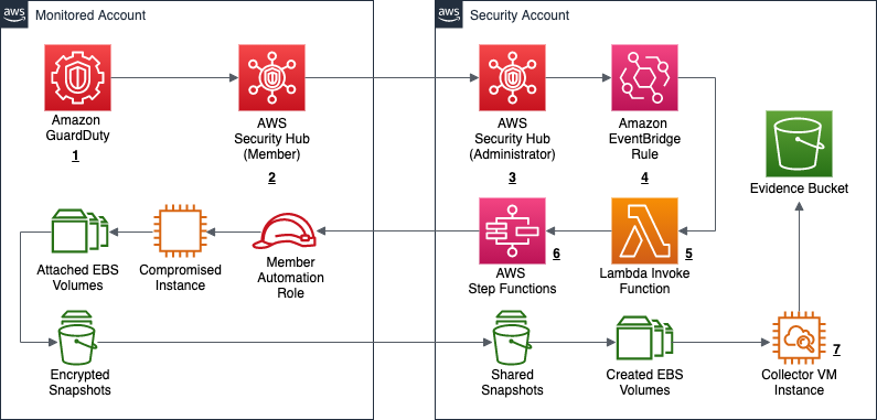
Another way of looking at this high-level workflow is from the service perspective, as shown in Figure 1.
Figure 1: Service workflow for forensic disk collection
The workflow in Figure 1 shows the following steps:
A GuardDuty finding is triggered for an instance in a monitored account. This example focuses on a GuardDuty finding, but the initial detection source can also be a custom event, or an event from a third party.
The Security Hub service in the monitored account receives the GuardDuty finding, and forwards it to the Security Hub service in the security account.
The Security Hub service in the security account receives the monitored account’s finding.
The Security Hub service creates an event over Amazon EventBridge for the GuardDuty findings, which is then caught by an EventBridge rule to forward to the DiskForensicsInvoke Lambda function. The following is the example event rule, which is included in the deployment. This example can be expanded or reduced to fit your use-case. By default, the example is set to disabled in CloudFormation. When you are ready to use the automation, you will need to enable it.
The DiskForensicsInvoke Lambda function receives the event from EventBridge, formats the event, and provides the formatted event as input to AWS Step Functions workflow.
The DiskForensicStepFunction workflow includes ten Lambda functions, from initial snapshot to streaming the evidence to the S3 bucket. After the Step Functions workflow enters the CopySnapshot state, it converts to a map state. This allows the workflow to have one thread per volume submitted, and ensures that each volume will be placed in the evidence bucket as quickly as possible without needing to wait for other steps to complete.
Figure 2: Forensic disk collection Step Function workflow
As shown in Figure 2, the following are the embedded Lambda functions in the DiskForensicStepFunction workflow:
CreateSnapshot – This function creates the initial snapshots for each EBS volume attached to the instance in question. It also records instance metadata that is included with the snapshot data for each EBS volume. Required Environmental Variables: ROLE_NAME, EVIDENCE_BUCKET, LOG_GROUP
CheckSnapshot – This function checks to see if the snapshots from the previous step are completed. If not, the function retries with an exponential backoff. Required Environmental Variable: ROLE_NAME
CopySnapshot – This function copies the initial snapshot and ensures that it is using the forensics AWS Key Management Service (AWS KMS) key. This key is stored in the security account and will be used throughout the remainder of the process. Required Environmental Variables: ROLE_NAME, KMS_KEY
CheckCopySnapshot – This function checks to see if the snapshot from the previous step is completed. If not, the function retries with exponential backoff. Required Environmental Variable: ROLE_NAME
ShareSnapshot – This function takes the copied snapshot using the forensics KMS key, and shares it with the security account. Required Environmental Variables: ROLE_NAME, SECURITY_ACCOUNT
FinalCopySnapshot – This function copies the shared snapshot into the security account, as the original shared snapshot is still owned by the monitored account. This ensures that a copy is available, in case it has to be referenced for additional processing later. Required Environmental Variable: KMS_KEY
FinalCheckSnapshot – This function checks to see if the snapshot from the previous step is completed. If not, the function fails and it retries with an exponential backoff.
CreateVolume – This function creates an EBS Magnetic volume from the snapshot in the previous step. These volumes created use magnetic disks, because they are required for consistent hash results from the dc3dd process. This volume cannot use a solid state drive (SSD), because the hash would be different each time. If the EBS Magnetic volume size is greater than or equal to 500GB, then Amazon EBS switches from using standard EBS Magnetic volumes to Throughput Optimized HDD (st1) volumes. Required Environmental Variables: KMS_KEY, SUPPORTED_AZS
RunInstance – This function launches one EC2 instance per volume, to be used in streaming the volume to the S3 bucket. The AMI passed by the environmental variable needs to be created using the provided Amazon EC2 Image Builder pipeline before deploying the environment. This function also passes some user data to the instance, artifact bucket, source volume name, and the incidentID. This information is used by the instance when placing the evidence into the S3 bucket. Required Environmental Variables: AMI_ID, INSTANCE_PROFILE_NAME, VPC_ID, SECURITY_GROUP
CreateInstanceWait – This function creates a 30-second wait, to allow the instance some additional time to spin up.
MountForensicVolume – This function checks the CloudWatch log group ForensicDiskReadiness, to see that the incrond service is running on the instance. If the incrond service is running, the function attaches the volume to the instance and then writes the final logs to the S3 bucket and CloudWatch Logs. Required Environmental Variable: LOG_GROUP
The instance that is created has pre-built tools and scripts on it from the template below using Image Builder. This instance uses the incrond tool to monitor /dev/disk/by-label for new devices being attached to the instance. After the MountForensicVolume Lambda function attaches the volume to the instance, a file is created in the /dev/disk/by-label directory for the attached volume. The incrond daemon starts the orchestrator script, which calls the collector script. The collector script uses the dc3dd tool to stream the bit-for-bit copy of the volume to S3. After the copy has completed, the image shuts down and is terminated. All logs from the process are sent to the S3 bucket and CloudWatch Logs.
The solution provided in the post includes the CloudFormation templates you need to get started, except for creation the initial EventBridge rule (which is provided in step 4 of the previous section). The solution includes an isolated VPC, subnets, security groups, roles, and more. The VPC provided does not provide any egress through an internet gateway or NAT gateway, and that is the recommended solution. The only connectivity provided is through the S3 gateway VPC endpoint and the CloudWatch Logs interface VPC endpoint (also deployed in the template).
Deploy the CloudFormation templates
To implement the solution outlined in this post, you need to deploy three separate AWS CloudFormation templates in the order described in this section.
diskForensicImageBuilder (security account)
First, you deploy diskForensicImageBuilder in the security account. This template contains the resources and AMIs needed to create and run the Image Builder pipeline that is required to build the collector VM. This pipeline installs the required binaries, and scripts, and updates the system.
Note: diskForensicImageBuilder is configured to use the default VPC and security group. If you have added restrictions or deleted your default VPC, you will need to modify the template.
To deploy the diskForensicImageBuilder template
To open the AWS CloudFormation console pre-loaded with the template, choose the following Launch Stack button.
In the AWS CloudFormation console, on the Specify Details page, enter a name for the stack.
Leave all default settings in place, and choose Next to configure the stack options.
Choose Next to review and scroll to the bottom of the page. Select the check box under the Capabilities section, next to of the acknowledgement:
I acknowledge that AWS CloudFormation might create IAM resources with custom names.
Choose Create Stack.
After the Image Builder pipeline has been created, on the Image pipelines page, choose Actions and select Run pipeline to manually run the pipeline to create the base AMI.
Figure 3: Run the new Image Builder pipeline
diskForensics (security account)
Second, you deploy diskForensics in the security account. This is a nested CloudFormation stack containing four CloudFormation templates. The four CloudFormation templates are as follows:
forensicResources – This stack holds all of the foundation for the solution, including the VPC and networking components, the S3 evidence bucket, CloudWatch log groups, and collectorVM instance profile.
Figure 4: Forensics VPC
forensicFunctions – This stack contains all of the Lambda functions referenced in the Step Functions workflow as well as the role used by the Lambda functions.
forensicStepFunction – This stack contains the Step Functions code, the role used by the Step Functions service, and the CloudWatch log group used by the service. It also contains an Amazon Simple Notification Service (SNS) topic used to alert on pipeline failure.
forensicStepFunctionInvoke – This stack contains the DiskForensicsInvoke Lambda function and the role used by that Lambda function that allows it to call the Step Function workflow.
Note: You need to have the following required variables to continue:
ArtifactBucketName
ORGID
ForensicsAMI
If your accounts are not using AWS Organizations, you can use a dummy string for now. It adds a condition statement to the forensics KMS key that you can update or remove later.
To deploy the diskForensics stack
To open the AWS CloudFormation console pre-loaded with the template, choose the following Launch Stack button.
In the AWS CloudFormation console, on the Specify Details page, enter a name for the stack.
For the ORGID field, enter the AWS Organizations ID.
Note: If you are not using AWS organizations, leave the default string. If you are deploying as multi-account without AWS Organizations, you will need to update the KMS key policy to remove the principalOrgID condition statements, and add the correct principals.
For the ArtifactBucketName field, enter the S3 bucket name you would like to use for your forensic artifacts.
Important: The ArtifactBucketName must be a globally unique name.
For the ForensicsAMI field, enter the AMI ID for the image that was created by Image Builder.
For the example in this post, leave the default values for all other fields. Customizing these fields allows you to customize this code example for your own purposes.
Choose Next to configure the stack options and leave all default settings in place.
Choose Next to review and scroll to the bottom of the page. Select the two check boxes under the Capabilities section, next to each of the acknowledgements:
I acknowledge that AWS CloudFormation might create IAM resources with custom names.
I acknowledge that AWS CloudFormation might require the following capability: CAPABILITY_AUTO_EXPAND.
Choose Create Stack.
After the stack has completed provisioning, subscribe to the Amazon SNS topic to receive pipeline alerts.
diskMember (each monitored account)
Third, you deploy diskMember in each monitored account. This stack contains the role and policy that the automation workflow needs to assume, so that it can create the initial snapshots and share the snapshot with the security account. If you are deploying this solution in a single account, you deploy diskMember in the security account.
Important: Ensure that all KMS keys that could be used to encrypt EBS volumes in each monitored account grant this role the ability to CreateGrant, Encrypt, Decrypt, ReEncrypt*, GenerateDataKey*, and Describe key. The default policy grants the permissions in AWS Identity and Access Management (IAM), but any restrictive resource policies could block the ability to create the initial snapshot and decrypt the snapshot when making the copy.
To deploy the diskMember stack
To open the AWS CloudFormation console pre-loaded with the template, choose the following Launch Stack button. If deploying across multiple accounts, consider using AWS CloudFormation StackSets for simplified multi-account deployment.
In the AWS CloudFormation console, on the Specify Details page, enter a name for the stack.
For the MasterAccountNum field, enter the account number for your security administrator account.
Choose Next to configure the stack options and leave all default settings in place.
Choose Next to review and scroll to the bottom of the page. Select the check box under the Capabilities section, next to the acknowledgement:
I acknowledge that AWS CloudFormation might create IAM resources with custom names.
Choose Create Stack.
Test the solution
Next, you can try this solution with an event sample to start the workflow.
To initiate a test run
Copy the following example GuardDuty event. The example uses the AWS Region us-east-1, but you can update the example to use another Region. Be sure to replace the account ID 0123456789012 with the account number of your monitored account, and replace the instance ID i-99999999 with the instance ID you would like to capture.
Navigate to the DiskForensicsInvoke Lambda function and add the GuardDuty event as a test event.
Choose Test. You should see a success for the invocation.
Navigate to the Step Functions workflow to monitor its progress. When the instances have terminated, all of the artifacts should be in the S3 bucket with additional logs in CloudWatch Logs.
Expected outputs
The forensic disk collection pipeline maintains logs of the actions throughout the process, and uploads the final artifacts to the S3 artifact bucket and CloudWatch Logs. This enables security teams to send forensic collection logs to log aggregation tools or service management tools for additional integrations. The expected outputs of the solution are detailed in the following sections, organized by destination.
S3 artifact outputs
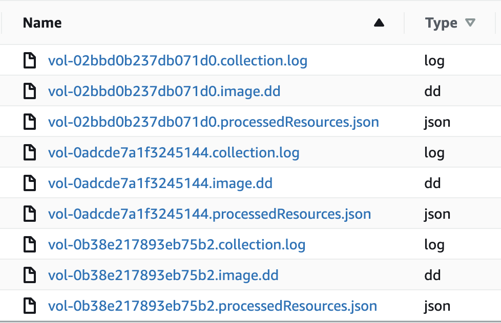
The S3 artifact bucket is the final destination for all logs and the raw disk images. For each security incident that triggers the Step Functions workflow, a new folder will be created with the name of the IncidentID. Included in this folder will be the JSON file that triggered the capture operation, the image (dd) files for the volumes, the capture log, and the resources associated with the capture operation, as shown in Figure 5.
Figure 5: Forensic artifacts in the S3 bucket
Forensic Disk Audit log group
The Forensic Disk Audit CloudWatch log group contains a log of where the Step Functions workflow was after creating the initial snapshots in the CreateSnapshot Lambda function. This includes the high-level finding information, as well as the metadata for each snapshot. Also included in this log group is the completed data around each completed disk collection operation, including all associated resources and the location of the forensic evidence in the S3 bucket. The following event is an example log demonstrating a completed capture. Notice all of the metadata provided under captured snapshots. Be sure to update the example to use the correct AWS Region. Replace the account ID 0123456789012 with the account number of your monitored account, and replace the instance ID i-99999999 with the instance ID you would like to capture.
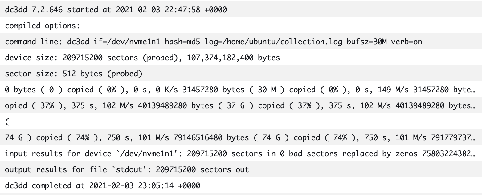
The Forensic Disk Capture CloudWatch log group contains the logs from the EC2Collector VM. These logs detail the operations taken by the instance, which include when the dc3dd command was executed, what the transfer speed was to the S3 bucket, what the hash of the volume was, and how long the total operation took to complete. The log example in Figure 6 shows the output of the disk capture on the collector instance.
Figure 6: Forensic Disk Capture logs
Cost and capture times
This solution may save you money over a traditional system that requires bastion hosts (jump boxes) and forensic instances to be readily available. With AWS, you pay only for the individual services you need, for as long as you use them. The cost of this solution is minimal, because charges are only incurred based on the logs or artifacts that you store in CloudWatch or Amazon S3, and the invocation of the Step Functions workflow. Additionally, resources such as the collectorVM are only created and used when needed.
This solution can also save you time. If an analyst was manually working through this workflow, it could take significantly more time than the automated solution. The following are some examples of collection times. You can see that even when the manual workflow time increases, the automated workflow time stays the same, because of how the solution scales.
Scenario 1: EC2 instance with one 8GB volume
Automated workflow: 11 minutes
Manual workflow: 15 minutes
Scenario 2: EC2 instance with four 8GB volumes
Automated workflow: 11 minutes
Manual workflow: 1 hour 10 minutes
Scenario 3: Four EC2 instances with one 8GB volume each
Automated workflow: 11 minutes
Manual workflow: 1 hour 20 minutes
Clean up and delete artifacts
To clean up the artifacts from the solution in this post, first delete all information in your artifact S3 bucket. Then delete the diskForensics stack, followed by the diskForensicImageBuilder stack, and finally the diskMember stack. You must also manually delete any EBS volumes or EBS snapshots created by the pipeline, these are not deleted automatically. You must also manually delete the AMI and images that are created and published by Image Builder.
Considerations
This solution covers EBS volume storage as the target for forensic disk capture. If your instances use Amazon EC2 Instance Stores in your environment, then you cannot snapshot and copy those volumes, because that data is not included in an EC2 snapshot operation. Instead, you should consider running the commands that are included in collector.sh script with AWS Systems Manager. The collector.sh script is included in the Image Builder recipe and uses dc3dd to stream a copy of the volume to Amazon S3.
If you have feedback about this post, submit comments in the Comments section below. If you have questions about this post, start a new thread on the Amazon GuardDuty forum or contact AWS Support.
Want more AWS Security how-to content, news, and feature announcements? Follow us on Twitter.
Microservices commonly communicate with JSON over HTTP/1.1. These technologies are ubiquitous and human-readable, but they aren’t optimized for communication between dozens or hundreds of microservices.
Next-generation Web technologies, including gRPC and HTTP/2, significantly improve communication speed and efficiency between microservices. AWS offers the most compelling experience for builders implementing microservices. Moreover, the addition of HTTP/2 and gRPC support in Application Load Balancer (ALB) provides an end-to-end solution for next-generation microservices. ALBs can inspect and route gRPC calls, enabling features like health checks, access logs, and gRPC-specific metrics.
This post demonstrates .NET microservices communicating with gRPC via Application Load Balancers. The microservices run on AWS Graviton2 instances, utilizing a custom-built 64-bit Arm processor to deliver up to 40% better price/performance than x86.
Architecture Overview
Modern Tacos is a new restaurant offering delivery. Customers place orders via mobile app, then they receive real-time status updates as their order is prepared and delivered.
The tutorial includes two microservices: “Submit Order” and “Track Order”. The Submit Order service receives orders from the app, then it calls the Track Order service to initiate order tracking. The Track Order service provides streaming updates to the app as the order is prepared and delivered.
Each microservice is deployed in an Amazon EC2 Auto Scaling group. Each group is behind an ALB that routes gRPC traffic to instances in the group.
This architecture is simplified to focus on ALB and gRPC functionality. Microservices are often deployed in containers for elastic scaling, improved reliability, and efficient resource utilization. ALB, gRPC, and .NET all work equally effectively in these architectures.
Comparing gRPC and JSON for microservices
Microservices typically communicate by sending JSON data over HTTP. As a text-based format, JSON is readable, flexible, and widely compatible. However, JSON also has significant weaknesses as a data interchange format. JSON’s flexibility makes enforcing a strict API specification difficult — clients can send arbitrary or invalid data, so developers must write rigorous data validation code. Additionally, performance can suffer at scale due to JSON’s relatively high bandwidth and parsing requirements. These factors also impact performance in constrained environments, such as smartphones and IoT devices. gRPC addresses all of these issues.
gRPC is an open-source framework designed to efficiently connect services. Instead of JSON, gRPC sends messages via a compact binary format called Protocol Buffers, or protobuf. Although protobuf messages are not human-readable, they utilize less network bandwidth and are faster to encode and decode. Operating at scale, these small differences multiply to a significant performance gain.
gRPC APIs define a strict contract that is automatically enforced for all messages. Based on this contract, gRPC implementations generate client and server code libraries in multiple programming languages. This allows developers to use higher-level constructs to call services, rather than programming against “raw” HTTP requests.
gRPC also benefits from being built on HTTP/2, a major revision of the HTTP protocol. In addition to the foundational performance and efficiency improvements from HTTP/2, gRPC utilizes the new protocol to support bi-directional streaming data. Implementing real-time streaming prior to gRPC typically required a completely separate protocol (such as WebSockets) that might not be supported by every client.
Instead of working with JSON, dynamic objects, or strings, C# developers calling a gRPC service use a strongly-typed client, automatically generated from the protobuf specification. This obviates much of the boilerplate validation required by JSON APIs, and it enables developers to use rich data structures. Additionally, the generated code enables full IntelliSense support in Visual Studio.
For example, the “Submit Order” microservice executes this code in order to call the “Track Order” microservice:
using var channel = GrpcChannel.ForAddress("https://track-order.example.com");

var trackOrderClient = new TrackOrder.Protos.TrackOrder.TrackOrderClient(channel);

var reply = await trackOrderClient.StartTrackingOrderAsync(new TrackOrder.Protos.Order
{
    DeliverTo = "Address",
    LastUpdated = Timestamp.FromDateTime(DateTime.UtcNow),
    OrderId = order.OrderId,
    PlacedOn = order.PlacedOn,
    Status = TrackOrder.Protos.OrderStatus.Placed
});
This code calls the StartTrackingOrderAsync method on the Track Order client, which looks just like a local method call. The method intakes a data structure that supports rich data types like DateTime and enumerations, instead of the loosely-typed JSON. The methods and data structures are defined by the Track Order service’s protobuf specification, and the .NET gRPC tools automatically generate the client and data structure classes without requiring any developer effort.
Configuring ALB for gRPC
To make gRPC calls to targets behind an ALB, create a load balancer target group and select gRPC as the protocol version. You can do this through the AWS Management Console, AWS Command Line Interface (CLI), AWS CloudFormation, or AWS Cloud Development Kit (CDK).
This CDK code creates a gRPC target group:
var targetGroup = new ApplicationTargetGroup(this, "TargetGroup", new ApplicationTargetGroupProps
{
    Protocol = ApplicationProtocol.HTTPS,
    ProtocolVersion = ApplicationProtocolVersion.GRPC,
    Vpc = vpc,
    Targets = new IApplicationLoadBalancerTarget {...}
});
gRPC requests work with target groups utilizing HTTP/2, but the gRPC protocol enables additional features including health checks, request count metrics, access logs that differentiate gRPC requests, and gRPC-specific response headers. gRPC also works with native ALB features like stickiness, multiple load balancing algorithms, and TLS termination.
Deploy the Tutorial
The sample provisions AWS resources via the AWS Cloud Development Kit (CDK). The CDK code is provided in C# so that .NET developers can use a familiar language.
Open a terminal (such as Bash) or a PowerShell prompt.
Configure the environment variables needed by the CDK. In the sample commands below, replace AWS_ACCOUNT_ID with your numeric AWS account ID. Replace AWS_REGION with the name of the region where you will deploy the sample, such as us-east-1 or us-west-2.
If you’re using a *nix shell such as Bash, run these commands:
Throughout this tutorial, replace RED TEXT with the appropriate value.
Save the directory path where you cloned the GitHub repository. In the sample commands below, replace EXAMPLE_DIRECTORY with this path.
In your terminal or PowerShell, run these commands:
cd EXAMPLE_DIRECTORY/src/ModernTacoShop/Common/cdk
cdk bootstrap --context domain-name=PARENT_DOMAIN_NAME
cdk deploy --context domain-name=PARENT_DOMAIN_NAME
The CDK output includes the name of the S3 bucket that will store deployment packages. Save the name of this bucket. In the sample commands below, replace SHARED_BUCKET_NAME with this name.
Deploy the Track Order microservice
Compile the Track Order microservice for the Arm microarchitecture utilized by AWS Graviton2 processors. The TrackOrder.csproj file includes a target that automatically packages the compiled microservice into a ZIP file. You will upload this ZIP file to S3 for use by CodeDeploy. Next, you will utilize the CDK to deploy the microservice’s AWS infrastructure, and then install the microservice on the EC2 instance via CodeDeploy.
The CDK stack deploys these resources:
An Amazon EC2 Auto Scaling group.
An Application Load Balancer (ALB) using gRPC, targeting the Auto Scaling group and configured with microservice health checks.
A subdomain for the microservice, targeting the ALB.
A DynamoDB table used by the microservice.
CodeDeploy infrastructure to deploy the microservice to the Auto Scaling group.
The Submit Order ALB routes the gRPC call to an instance.
The Submit Order instance stores order data.
The Submit Order instance calls the Track Order service via gRPC.
The Track Order ALB routes the gRPC call to an instance.
The Track Order instance stores tracking data.
The app calls the Track Order service, which streams the order’s location during delivery.
Test the microservices
Once the CodeDeploy deployments have completed, test both microservices.
First, check the load balancers’ status. Go to Target Groups in the AWS Management Console, which will list one target group for each microservice. Click each target group, then click “Targets” in the lower details pane. Every EC2 instance in the target group should have a “healthy” status.
If a service is healthy, it will return an empty JSON object.
Run the mobile app
You will run a pre-compiled version of the app on AWS Device Farm, which lets you test on a real device without managing any infrastructure. Alternatively, compile your own version via the AndroidApp.FrontEnd project within the solution located at EXAMPLE_DIRECTORY/src/ModernTacoShop/AndroidApp/AndroidApp.sln.
Go to Device Farm in the AWS Management Console. Under “Mobile device testing projects”, click “Create a new project”. Enter “ModernTacoShop” as the project name, and click “Create Project”. In the ModernTacoShop project, click the “Remote access” tab, then click “Start a new session”. Under “Choose a device”, select the Google Pixel 3a running OS version 10, and click “Confirm and start session”.
Once the session begins, click “Upload” in the “Install applications” section. Unzip and upload the APK file located at EXAMPLE_DIRECTORY/src/ModernTacoShop/AndroidApp/com.example.modern_tacos.grpc_tacos.apk.zip, or upload an APK that you created.
Once the app has uploaded, drag up from the bottom of the device screen in order to reach the “All apps” screen. Click the ModernTacos app to launch it.
Once the app launches, enter the parent domain name in the “Domain Name” field. Click the “+” and “-“ buttons next to each type of taco in order to create your order, then click “Submit Order”. The order status will initially display as “Preparing”, and will switch to “InTransit” after about 30 seconds. The Track Order service will stream a random route to the app, updating with new position data every 5 seconds. After approximately 2 minutes, the order status will change to “Delivered” and the streaming updates will stop.
Once you’ve run a successful test, click “Stop session” in the console.
Cleaning up
To avoid incurring charges, use the cdk destroy command to delete the stacks in the reverse order that you deployed them.
In addition to deleting the stacks, you must delete the Route 53 hosted zone and the Device Farm project.
Conclusion
This post demonstrated multiple next-generation technologies for microservices, including end-to-end HTTP/2 and gRPC communication over Application Load Balancer, AWS Graviton2 processors, and .NET 5. These technologies enable builders to create microservices applications with new levels of performance and efficiency.
Matt Cline
Matt Cline is a Solutions Architect at Amazon Web Services, supporting customers in his home city of Pittsburgh PA. With a background as a full-stack developer and architect, Matt is passionate about helping customers deliver top-quality applications on AWS. Outside of work, Matt builds (and occasionally finishes) scale models and enjoys running a tabletop role-playing game for his friends.
Ulili Nhaga
Ulili Nhaga is a Cloud Application Architect at Amazon Web Services in San Diego, California. He helps customers modernize, architect, and build highly scalable cloud-native applications on AWS. Outside of work, Ulili loves playing soccer, cycling, Brazilian BBQ, and enjoying time on the beach.
Commercial off-the-shelf software and third-party services can present an integration challenge in event-driven workflows when they do not natively support AWS APIs. This is even more impactful when a workflow is subject to unpredicted usage spikes, and you want to increase decoupling and fault tolerance. Given the third-party nature of services, polling an Amazon Simple Queue Service (SQS) queue and having built-in AWS API handling logic may not be an immediate option.
In such cases, AWS Lambda helps out-task the Amazon SQS queue integration and AWS API handling to an additional layer. The success of this depends on how well exception handling is implemented across the different interacting services. In this blog post, we outline issues to consider when adopting this design pattern. We also share a reusable solution.
Design pattern for third-party integration with SQS
With this design pattern, one or more services (producers) asynchronously invoke other third-party downstream consumer services. They publish messages to an Amazon SQS queue, which acts as buffer for requests. Producers provide all commands and other parameters required for consumer service execution with the message.
Figure 1. On-premises and AWS queue integration for third-party services using AWS Lambda
The message broker asynchronously invokes the API in ‘fire-and-forget’ mode. Therefore, error handling must be built in to respond to API invocation errors. In an event-driven scenario, an error will be invoked if you asynchronously call the third-party service hundreds or thousands of times and reach Service Quotas. This is a potential issue with RunTask API actions, or a large volume of concurrent tasks running on AWS Fargate. Two mechanisms can help implement troubleshooting API request errors.
API retries with exponential backoff. The message broker retries for a number of times with configurable sleep intervals and exponential backoff in-between. This enforces progressively longer waits between retries for consecutive error responses. If the RunTask API fails to process the request and initiate the third-party service, the message remains in the queue for a subsequent retry. The AWS General Reference provides further guidance.
API error handling. Error handling and consequent logging should be implemented at every step. Since there are several services working together in tandem, crucial debugging information from errors may be lost. Additionally, error handling also provides opportunity to define automated corrective actions or notifications on event occurrence. The message broker can publish failure notifications including the root cause to an Amazon Simple Notification Service (SNS) topic.
SNS topic subscription can be configured via different protocols. You can email a distribution group for active monitoring and processing of errors. If persistence is required for messages that failed to process, error handling can be associated directly with SQS by configuring a dead letter queue.
Reference implementation for third-party integration with SQS
We implemented the design pattern in Figure 1, with Broad Institute’s Cell Painting application workflow. This is for morphological profiling from microscopy cell images running on Amazon EC2. It interacts with CellProfiler version 3.0 cell image analysis software as the downstream consumer hosted on ECS/Fargate. Every invocation of CellProfiler required approximately 1,500 tasks for a single processing step.
Resource constraints determined the rate of scale-out. In this case, it was for an Amazon ECS task creation. Address space for Amazon ECS subnets should be large enough to prevent running out of available IPs within your VPC. If Amazon ECS Service Quotas provide further constraints, a quota increase can be requested.
Exceptions must be handled both when validating and initiating requests. As part of the validation workflow, exceptions are captured as follows, also shown in Figure 2.
1. Invalid arguments exception. The message broker validates that the SQS message contains all the needed information to initiate the ECS task. This information includes subnets, security groups and container names required to start the ECS task, and else raises exception.
2. Retry limit exception. On each iteration, the message broker will evaluate whether the SQS retry limit has been reached, before invoking the RunTask API. It will then exit, by sending failure notification to SNS when the retry limit is reached.
Figure 2. Exception handling flow during request validation
As part of the initiation workflow, exceptions are handled as follows, shown in Figure 3:
1. ECS/Fargate API and concurrent execution limitations. The message broker catches API exceptions when calling the API RunTask operation. These exceptions can include:
When the call to the launch tasks exceeds the maximum allowed API request limit for your AWS account
When failing to retrieve security group information
When you have reached the limit on the number of tasks you can run concurrently
With each of the preceding exceptions, the broker will increase the retry count.
2. Networking and IP space limitations. Network interface timeouts received after initiating the ECS task set off an Amazon CloudWatch Events rule, causing the message broker to re-initiate the ECS task.
Figure 3. Exception handling flow during request initiation
While we specifically address downstream consumer services running on ECS/Fargate, this solution can be adjusted for third-party services running on Amazon EC2 or EKS. With EC2, the message broker must be adjusted to interact with the RunInstances API, and include troubleshooting API request errors. Integration with downstream consumers on Amazon EKS requires that the AWS Lambda function is associated via the IAM role with a Kubernetes service account. A Python client for Kubernetes can be used to simplify interaction with the Kubernetes REST API and AWS Lambda would invoke the run API.
Conclusion
This pattern is useful when queue polling is not an immediate option. This is typical with event-driven workflows involving third-party services and vendor applications subject to unpredictable, intermittent load spikes. Exception handling is essential for these types of workflows. Offloading AWS API handling to a separate layer orchestrated by AWS Lambda can improve the resiliency of such third-party services on AWS. This pattern represents an incremental optimization until the third party provides native SQS integration. It can be achieved with the initial move to AWS, for example as part of the V1 AWS design strategy for third-party services.
Some limitations should be acknowledged. While the pattern enables graceful failure, it does not prevent the overloading of the ECS RunTask API. By invoking Amazon ECS RunTask API in ‘fire-and-forget’ mode, it does not monitor service execution once a task was successfully invoked. Therefore, it should be adopted when direct queue polling is not an option. In our example, Broad Institute’s CellProfiler application enabled direct queue polling with its subsequent product version of Distributed CellProfiler.
Further reading
The referenced deployment with consumer services on Amazon ECS can be accessed via AWSLabs.
To help customers using the Terraform for multi-cloud infrastructure deployment, we have introduced a new feature in the AWS Config Rule Development Kit (RDK) that allows you to export custom AWS Config rules to Terraform files so that you can deploy the RDK rules with Terraform.
This blog post is a complement to the previous post – How to develop custom AWS Config rules using the Rule Development Kit. Here I will show you how to prototype, develop, and deploy custom AWS Config rules. The steps for prototyping and developing the custom AWS Config rules remain identical, while a variation exists in the deployment step, which I’ll walk you through in detail. I would encourage you to review the previous blog post, so that you can follow along here.
In this post, you will learn how to export the custom AWS Config rule to Terraform files and deploy to AWS using the Terraform.
Background
RDK doesn’t support the Terraform for rules deployment, which is impacting customers using the Terraform (“Infrastructure As Code”) to provision AWS infrastructure. Therefore, we have provided one more option to deploy the rules by using the Terraform.
Getting Started
The first step is making sure that you installed the latest RDK version. After you have defined an AWS Config rule and prototyped using the AWS Config RDK as described in the previous blog post, follow the steps below to deploy the various AWS Config components across the compliance and satellite accounts.
Prerequisites
Validate that you downloaded the RDK that supports “export”, using the command “rdk export -h”, and you should see the below output. If the installed RDK doesn’t support the export feature, then update it by using the command “pip install rdk”
(venv) 8c85902e4110:7RDK test$ rdk export -h

usage: rdk export [-h] [-s RULESETS] [--all] [--lambda-layers LAMBDA_LAYERS]
                  [--lambda-subnets LAMBDA_SUBNETS]
                  [--lambda-security-groups LAMBDA_SECURITY_GROUPS]
                  [--lambda-role-arn LAMBDA_ROLE_ARN]
                  [--rdklib-layer-arn RDKLIB_LAYER_ARN] -v {0.11,0.12} -f
                  {terraform}
                  [<rulename> [<rulename> ...]]

Used to export the Config Rule to terraform file.

positional arguments:
  <rulename>            Rule name(s) to export to a file.

optional arguments:
  -h, --help            show this help message and exit
  -s RULESETS, --rulesets RULESETS
                        comma-delimited list of RuleSet names
  --all, -a             All rules in the working directory will be deployed.
  --lambda-layers LAMBDA_LAYERS
                        [optional] Comma-separated list of Lambda Layer ARNs
                        to deploy with your Lambda function(s).
  --lambda-subnets LAMBDA_SUBNETS
                        [optional] Comma-separated list of Subnets to deploy
                        your Lambda function(s).
  --lambda-security-groups LAMBDA_SECURITY_GROUPS
                        [optional] Comma-separated list of Security Groups to
                        deploy with your Lambda function(s).
  --lambda-role-arn LAMBDA_ROLE_ARN
                        [optional] Assign existing iam role to lambda
                        functions. If omitted, new lambda role will be
                        created.
  --rdklib-layer-arn RDKLIB_LAYER_ARN
                        [optional] Lambda Layer ARN that contains the desired
                        rdklib. Note that Lambda Layers are region-specific.
  -v {0.11,0.12}, --version {0.11,0.12}
                        Terraform version
  -f {terraform}, --format {terraform}
                        Export Format
Create your rule
Create your rule by using the command below which creates the MY_FIRST_RULE rule.
This creates the three files below. Edit the “MY_FIRST_RULE.py” as per your business requirement, as described in the “Edit” section of this blog.
7RDK test$ cd MY_FIRST_RULE/
(venv) 8c85902e4110:MY_FIRST_RULE test$ls
MY_FIRST_RULE.py        MY_FIRST_RULE_test.py   parameters.json
Export your rule to Terraform
Use the command below to export your rule to the Terraform files, which supports the two versions of Terraform (0.11 and 0.12). Use the “-v” argument to specify the version.
test$ cd ..
7RDK test$ rdk export MY_FIRST_RULE -f terraform -v 0.12
Running export
Found Custom Rule.
Zipping MY_FIRST_RULE
Zipping complete.
terraform version: 0.12
Export completed.This will generate three .tf files.
7RDK test$
This creates the four files.
<< rule-name >>_rule.tf :
This script uploads the rule to the Amazon S3 bucket, deploys the lambda, and creates the AWS config rule and the required IAM roles/policies.
7RDK test$ cd MY_FIRST_RULE/
(venv) 8c85902e4110:MY_FIRST_RULE test$ ls -1
MY_FIRST_RULE.py
MY_FIRST_RULE.zip
MY_FIRST_RULE_test.py
my_first_rule.tfvars.json
my_first_rule_rule.tf
my_first_rule_variables.tf
parameters.json
Deploy your rule using the Terraform
Initialize the Terraform by using “terraform init” to download the AWS provider Plug-In.
MY_FIRST_RULE test$ terraform init

Initializing the backend...

Initializing provider plugins...
- Checking for available provider plugins...
- Downloading plugin for provider "aws" (hashicorp/aws) 2.70.0...

The following providers do not have any version constraints in configuration,
so the latest version was installed.

To prevent automatic upgrades to new major versions that may contain breaking
changes, it is recommended to add version = "..." constraints to the
corresponding provider blocks in configuration, with the constraint strings
suggested below.

* provider.aws: version = "~> 2.70"

Terraform has been successfully initialized!
To deploy the config rules, your role should have the permissions and should mention the role ARN in my_rule.tfvars.json
To apply the Terraform, it requires two arguments:
var-file: Terraform script variable file name, created while exporting the rule using RDK.
source_bucket: Your Amazon S3 bucket name, to upload the config rule lambda code.
Make sure that AWS provider is configured for your Terraform environment as mentioned in the docs.
MY_FIRST_RULE test$ terraform apply -var-file=my_first_rule.tfvars.json --var source_bucket=config-bucket-xxxxx

aws_iam_policy.awsconfig_policy[0]: Creating...
aws_iam_role.awsconfig[0]: Creating...
aws_s3_bucket_object.rule_code: Creating...
aws_iam_role.awsconfig[0]: Creation complete after 3s [id=my_first_rule-awsconfig-role]
aws_iam_role_policy_attachment.readonly-role-policy-attach[0]: Creating...
aws_iam_policy.awsconfig_policy[0]: Creation complete after 4s [id=arn:aws:iam::xxxxxxxxxxxx:policy/my_first_rule-awsconfig-policy]
aws_iam_role_policy_attachment.awsconfig_policy_attach[0]: Creating...
aws_s3_bucket_object.rule_code: Creation complete after 5s [id=MY_FIRST_RULE.zip]
aws_lambda_function.rdk_rule: Creating...
aws_iam_role_policy_attachment.readonly-role-policy-attach[0]: Creation complete after 2s [id=my_first_rule-awsconfig-role-20200726023315892200000001]
aws_iam_role_policy_attachment.awsconfig_policy_attach[0]: Creation complete after 3s [id=my_first_rule-awsconfig-role-20200726023317242000000002]
aws_lambda_function.rdk_rule: Still creating... [10s elapsed]
aws_lambda_function.rdk_rule: Creation complete after 18s [id=RDK-Rule-Function-MY_FIRST_RULE]
aws_lambda_permission.lambda_invoke: Creating...
aws_config_config_rule.event_triggered[0]: Creating...
aws_lambda_permission.lambda_invoke: Creation complete after 2s [id=AllowExecutionFromConfig]
aws_config_config_rule.event_triggered[0]: Creation complete after 4s [id=MY_FIRST_RULE]

Apply complete! Resources: 8 added, 0 changed, 0 destroyed.
Login to your AWS console to validate the deployed config rule.
Clean up
Enter the following command to remove all the resources.
MY_FIRST_RULE test$ terraform destroy
Conclusion
With this new feature, you can export the AWS config rules developed by RDK to the Terraform, and integrate these files into your Terraform CI/CD pipeline to provision the config rules in AWS without using the RDK.
So you’re expanding your reach by leveraging voice interfaces for your applications through the Alexa ecosystem. You’ve experimented with a new Alexa Skill via the Alexa Developer Console, and now you’re ready to productionalize it for your customers. How exciting!
You are also a proponent of Infrastructure as Code (IaC). You appreciate the speed, consistency, and change management capabilities enabled by IaC. Perhaps you have other applications that you provision and maintain via DevOps practices, and you want to deploy and maintain your Alexa Skill in the same way. Great idea!
That’s where AWS CloudFormation and the AWS Cloud Development Kit (AWS CDK) come in. AWS CloudFormation lets you treat infrastructure as code, so that you can easily model a collection of related AWS and third-party resources, provision them quickly and consistently, and manage them throughout their lifecycles. The AWS CDK is an open-source software development framework for modeling and provisioning your cloud application resources via familiar programming languages, like TypeScript, Python, Java, and .NET. AWS CDK utilizes AWS CloudFormation in the background in order to provision resources in a safe and repeatable manner.
In this post, we show you how to achieve Infrastructure as Code for your Alexa Skills by leveraging powerful AWS CDK features.
Concepts
Alexa Skills Kit (ASK)
In addition to the Alexa Developer Console, skill developers can utilize the Alexa Skills Kit (ASK) to build interactive voice interfaces for Alexa. ASK provides a suite of self-service APIs and tools for building and interacting with Alexa Skills, including the ASK CLI, the Skill Management API (SMAPI), and SDKs for Node.js, Java, and Python. These tools provide a programmatic interface for your Alexa Skills in order to update them with code rather than through a user interface.
AWS CloudFormation
AWS CloudFormation lets you create templates written in either YAML or JSON format to model your infrastructure in code form. CloudFormation templates are declarative and idempotent, allowing you to check them into a versioned code repository, deploy them automatically, and track changes over time.
The ASK CloudFormation resource allows you to incorporate Alexa Skills in your CloudFormation templates alongside your other infrastructure. However, this has limitations that we’ll discuss in further detail in the Problem section below.
AWS Cloud Development Kit (AWS CDK)
Think of the AWS CDK as a developer-centric toolkit that leverages the power of modern programming languages to define your AWS infrastructure as code. When AWS CDK applications are run, they compile down to fully formed CloudFormation JSON/YAML templates that are then submitted to the CloudFormation service for provisioning. Because the AWS CDK leverages CloudFormation, you still enjoy every benefit provided by CloudFormation, such as safe deployment, automatic rollback, and drift detection. AWS CDK currently supports TypeScript, JavaScript, Python, Java, C#, and Go (currently in Developer Preview).
Perhaps the most compelling part of AWS CDK is the concept of constructs—the basic building blocks of AWS CDK apps. The three levels of constructs reflect the level of abstraction from CloudFormation. A construct can represent a single resource, like an AWS Lambda Function, or it can represent a higher-level component consisting of multiple AWS resources.
The three different levels of constructs begin with low-level constructs, called L1 (short for “level 1”) or Cfn (short for CloudFormation) resources. These constructs directly represent all of the resources available in AWS CloudFormation. The next level of constructs, called L2, also represents AWS resources, but it has a higher-level and intent-based API. They provide not only similar functionality, but also the defaults, boilerplate, and glue logic you’d be writing yourself with a CFN Resource construct. Finally, the AWS Construct Library includes even higher-level constructs, called L3 constructs, or patterns. These are designed to help you complete common tasks in AWS, often involving multiple resource types. Learn more about constructs in the AWS CDK developer guide.
One L2 construct example is the Custom Resources module. This lets you execute custom logic via a Lambda Function as part of your deployment in order to cover scenarios that the AWS CDK doesn’t support yet. While the Custom Resources module leverages CloudFormation’s native Custom Resource functionality, it also greatly reduces the boilerplate code in your CDK project and simplifies the necessary code in the Lambda Function. The open-source construct library referenced in the Solution section of this post utilizes Custom Resources to avoid some limitations of what CloudFormation and CDK natively support for Alexa Skills.
Problem
The primary issue with utilizing the Alexa::ASK::Skill CloudFormation resource, and its corresponding CDK CfnSkill construct, arises when you define the Skill’s backend Lambda Function in the same CloudFormation template or CDK project. When the Skill’s endpoint is set to a Lambda Function, the ASK service validates that the Skill has the appropriate permissions to invoke that Lambda Function. The best practice is to enable Skill ID verification in your Lambda Function. This effectively restricts the Lambda Function to be invokable only by the configured Skill ID. The problem is that in order to configure Skill ID verification, the Lambda Permission must reference the Skill ID, so it cannot be added to the Lambda Function until the Alexa Skill has been created. If we try creating the Alexa Skill without the Lambda Permission in place, insufficient permissions will cause the validation to fail. The endpoint validation causes a circular dependency preventing us from defining our desired end state with just the native CloudFormation resource.
Unfortunately, the AWS CDK also does not yet support any L2 constructs for Alexa skills. While the ASK Skill Management API is another option, managing imperative API calls within a CI/CD pipeline would not be ideal.
Solution
Overview
AWS CDK is extensible in that if there isn’t a native construct that does what you want, you can simply create your own! You can also publish your custom constructs publicly or privately for others to leverage via package registries like npm, PyPI, NuGet, Maven, etc.
We could write our own code to solve the problem, but luckily this use case allows us to leverage an open-source construct library that addresses our needs. This library is currently available for TypeScript (npm) and Python (PyPI).
The complete solution can be found at the GitHub repository, here. The code is in TypeScript, but you can easily port it to another language if necessary. See the AWS CDK Developer Guide for more guidance on translating between languages.
Prerequisites
You will need the following in order to build and deploy the solution presented below. Please be mindful of any prerequisites for these tools.
Alexa Developer Account
AWS Account
Docker
Used by CDK for bundling assets locally during synthesis and deployment.
See Docker website for installation instructions based on your operating system.
AWS CLI
Used by CDK to deploy resources to your AWS account.
See AWS CLI user guide for installation instructions based on your operating system.
Node.js
The CDK Toolset and backend runs on Node.js regardless of the project language. See the detailed requirements in the AWS CDK Getting Started Guide.
See the Node.js website to download the specific installer for your operating system.
Clone Code Repository and Install Dependencies
The code for the solution in this post is located in this repository on GitHub. First, clone this repository and install its local dependencies by executing the following commands in your local Terminal:
# clone repository
git clone https://github.com/aws-samples/aws-devops-blog-alexa-cdk-walkthrough
# navigate to project directory
cd aws-devops-blog-alexa-cdk-walkthrough
# install dependencies
npm install
Note that CLI commands in the sections below (ask, cdk) use npx. This executes the command from local project binaries if they exist, or, if not, it installs the binaries required to run the command. In our case, the local binaries are installed as part of the npm install command above. Therefore, npx will utilize the local version of the binaries even if you already have those tools installed globally. We use this method to simplify setup and alleviate any issues arising from version discrepancies.
Get Alexa Developer Credentials
To create and manage Alexa Skills via CDK, we will need to provide Alexa Developer account credentials, which are separate from our AWS credentials. The following values must be supplied in order to authenticate:
Vendor ID: Represents the Alexa Developer account.
Client ID: Represents the developer, tool, or organization requiring permission to perform a list of operations on the skill. In this case, our AWS CDK project.
Client Secret: The secret value associated with the Client ID.
Refresh Token: A token for reauthentication. The ASK service uses access tokens for authentication that expire one hour after creation. Refresh tokens do not expire and can retrieve a new access token when needed.
Follow the steps below to retrieve each of these values.
Get Alexa Developer Vendor ID
Easily retrieve your Alexa Developer Vendor ID from the Alexa Developer Console.
After logging in, on the main screen click on the “Settings” tab.
Your Vendor ID is listed in the “My IDs” section. Note this value.
Create Login with Amazon (LWA) Security Profile
The Skill Management API utilizes Login with Amazon (LWA) for authentication, so first we must create a security profile for LWA under the same Amazon account that we will use to create the Alexa Skill.
Navigate to the LWA console and login with your Amazon account.
Click the “Create a New Security Profile” button.
Fill out the form with a Name, Description, and Consent Privacy Notice URL, and then click “Save”.
The new Security Profile should now be listed. Hover over the gear icon, located to the right of the new profile name, and click “Web Settings”.
Click the “Edit” button and add the following under “Allowed Return URLs”:
Click the “Show Secret” button to reveal your Client Secret. Note your Client ID and Client Secret.
Get Refresh Token from ASK CLI
Your Client ID and Client Secret let you generate a refresh token for authenticating with the ASK service.
Navigate to your local Terminal and enter the following command, replacing <your Client ID> and <your Client Secret> with your Client ID and Client Secret, respectively:
# ensure you are in the root directory of the repository
npx ask util generate-lwa-tokens --client-id "<your Client ID>" --client-confirmation "<your Client Secret>" --scopes "alexa::ask:skills:readwrite alexa::ask:models:readwrite"
A browser window should open with a login screen. Supply credentials for the same Amazon account with which you created the LWA Security Profile previously.
Click the “Allow” button to grant the refresh token appropriate access to your Amazon Developer account.
Return to your Terminal. The credentials, including your new refresh token, should be printed. Note the value in the refresh_token field.
NOTE: If your Terminal shows an error like CliFileNotFoundError: File ~/.ask/cli_config not exists., you need to first initialize the ASK CLI with the command npx ask configure. This command will open a browser with a login screen, and you should enter the credentials for the Amazon account with which you created the LWA Security Profile previously. After signing in, return to your Terminal and enter n to decline linking your AWS account. After completing this process, try the generate-lwa-tokens command above again.
NOTE: If your Terminal shows an error like CliError: invalid_client, make sure that you have included the quotation marks (") around the --client_id and --client-confirmation arguments.
Add Alexa Developer Credentials to AWS SSM Parameter Store / AWS Secrets Manager
Our AWS CDK project requires access to the Alexa Developer credentials we just generated (Client ID, Client Secret, Refresh Token) in order to create and manage our Skill. To avoid hard-coding these values into our code, we can store the values in AWS Systems Manager (SSM) Parameter Store and AWS Secrets Manager, and then retrieve them programmatically when deploying our CDK project. In our case, we are using SSM Parameter Store to store the non-sensitive values in plaintext, and Secrets Manager to store the secret values in encrypted form.
The repository contains a shell script at scripts/upload-credentials.sh that can create the appropriate parameters and secrets via AWS CLI. You’ll just need to supply the credential values from the previous steps. Alternatively, instructions for creating parameters and secrets via the AWS Console or AWS CLI can each be found in the AWS Systems Manager User Guide and AWS Secrets Manager User Guide.
You will need the following resources created in your AWS account before proceeding:
Name
Service
Type
/alexa-cdk-blog/alexa-developer-vendor-id
SSM Parameter Store
String
/alexa-cdk-blog/lwa-client-id
SSM Parameter Store
String
/alexa-cdk-blog/lwa-client-secret
Secrets Manager
Plaintext / secret-string
/alexa-cdk-blog/lwa-refresh-token
Secrets Manager
Plaintext / secret-string
Code Walkthrough
Skill Package
When you programmatically create an Alexa Skill, you supply a Skill Package, which is a zip file consisting of a set of files defining your Skill. A skill package includes a manifest JSON file, and optionally a set of interaction model files, in-skill product files, and/or image assets for your skill. See the Skill Management API documentation for details regarding skill packages.
The repository contains a skill package that defines a simple Time Teller Skill at src/skill-package. If you want to use an existing Skill instead, replace the contents of src/skill-package with your skill package.
If you want to export the skill package of an existing Skill, use the ASK CLI:
Find the Skill you want to export and click the link under the name “Copy Skill ID”. Either make sure this stays on your clipboard or note the Skill ID for the next step.
Navigate to your local Terminal and enter the following command, replacing <your Skill ID> with your Skill ID:
# ensure you are in the root directory of the repository
cd src
npx ask smapi export-package --stage development --skill-id <your Skill ID>
NOTE: To export the skill package for a live skill, replace --stage development with --stage live.
NOTE: The CDK code in this solution will dynamically populate the manifest.apis section in skill.json. If that section is populated in your skill package, either clear it out or know that it will be replaced when the project is deployed.
Skill Backend Lambda Function
The Lambda Function code for the Time Teller Alexa Skill’s backend also resides within the CDK project at src/lambda/skill-backend. If you want to use an existing Skill instead, replace the contents of src/lambda/skill-backend with your Lambda code. Also note the following if you want to use your own Lambda code:
The CDK code in the repository assumes that the Lambda Function runtime is Python. However, you can modify for another runtime if necessary by using either the aws-lambda or aws-lambda-nodejs CDK module instead of aws-lambda-python.
If you’re using your own Python Lambda Function code, please note the following to ensure the Lambda Function definition compatibility in the sample CDK project. If your Lambda Function varies from what is below, then you may need to modify the CDK code. See the Python Lambda code in the repository for an example.
The skill-backend/ directory should contain all of the necessary resources for your Lambda Function. For Python functions, this should include at least a file named index.py that contains your Lambda entrypoint, and a requirements.txt file containing your pip dependencies.
For Python functions, your Lambda handler function should be called handler(). This generally looks like handler = SkillBuilder().lambda_handler() when using the Python ASK SDK.
Open-Source Alexa Skill Construct Library
As mentioned above, this solution utilizes an open-source construct library to create and manage the Alexa Skill. This construct library utilizes the L1 CfnSkill construct along with other L1 and L2 constructs to create a complete Alexa Skill with a functioning backend Lambda Function. Utilizing this construct library means that we are no longer limited by the shortcomings of only using the Alexa::ASK::Skill CloudFormation resource or L1 CfnSkill construct.
Look into the construct library code if you’re curious. There’s only one construct—Skill—and you can follow the code to see how it dodges the Lambda Permission issue.
CDK Stack
The CDK stack code is located in lib/alexa-cdk-stack.ts. Let’s dive in to understand what’s happening. We’ll look at one section at a time:
...
const PARAM_PREFIX = '/alexa-cdk-blog/'

export class AlexaCdkStack extends cdk.Stack {
  constructor(scope: cdk.Construct, id: string, props?: cdk.StackProps) {
    super(scope, id, props);

    // Get Alexa Developer credentials from SSM Parameter Store/Secrets Manager.
    // NOTE: Parameters and secrets must have been created in the appropriate account before running `cdk deploy` on this stack.
    //       See sample script at scripts/upload-credentials.sh for how to create appropriate resources via AWS CLI.
    const alexaVendorId = ssm.StringParameter.valueForStringParameter(this, `${PARAM_PREFIX}alexa-developer-vendor-id`);
    const lwaClientId = ssm.StringParameter.valueForStringParameter(this, `${PARAM_PREFIX}lwa-client-id`);
    const lwaClientSecret = cdk.SecretValue.secretsManager(`${PARAM_PREFIX}lwa-client-secret`);
    const lwaRefreshToken = cdk.SecretValue.secretsManager(`${PARAM_PREFIX}lwa-refresh-token`);
    ...
  }
}
First, within the stack’s constructor, after calling the constructor of the base class, we retrieve the credentials we uploaded earlier to SSM and Secrets Manager. This lets us to store our account credentials in a safe place—encrypted in the case of our lwaClientSecret and lwaRefreshToken secrets—and we avoid storing sensitive data in plaintext or source control.
...
export class AlexaCdkStack extends cdk.Stack {
  constructor(scope: cdk.Construct, id: string, props?: cdk.StackProps) {
    ...
    // Create the Lambda Function for the Skill Backend
    const skillBackend = new lambdaPython.PythonFunction(this, 'SkillBackend', {
      entry: 'src/lambda/skill-backend',
      timeout: cdk.Duration.seconds(7)
    });
    ...
  }
}
Next, we create the Lambda Function containing the skill’s backend logic. In this case, we are using the aws-lambda-python module. This transparently handles every aspect of the dependency installation and packaging for us. Rather than leave the default 3-second timeout, specify a 7-second timeout to correspond with the Alexa service timeout of 8 seconds.
Finally, we create our Skill! All we need to do is pass the Lambda Function with the Skill’s backend code into where the skill package is located, as well as the credentials for authenticating into our Alexa Developer account. All of the wiring for deploying the skill package and connecting the Lambda Function to the Skill is handled transparently within the construct code.
Deploy CDK project
Now that all of our code is in place, we can deploy our project and test it out!
Make sure that you have bootstrapped your AWS account for CDK. If not, you can bootstrap with the following command:
# ensure you are in the root directory of the repository
npx cdk bootstrap
Make sure that the Docker daemon is running locally. This is generally done by starting the Docker Desktop application.
You can also use the following Terminal command to determine whether the Docker daemon is running. The command will return an error if the daemon is not running.
docker ps -q
See more details regarding starting the Docker daemon based on your operating system via the Docker website.
Synthesize your CDK project in order to confirm that your project is building properly.
# ensure you are in the root directory of the repository
npx cdk synth
NOTE: In addition to generating the CloudFormation template for this project, this command also bundles the Lambda Function code via Docker, so it may take a few minutes to complete.
Deploy!
# ensure you are in the root directory of the repository
npx cdk deploy
Feel free to review the IAM policies that will be created, and enter y to continue when prompted.
If you would like to skip the security approval requirement and deploy in one step, use cdk deploy --require-approval never instead.
Check it out!
Once your project finishes deploying, take a look at your new Skill!
After logging in, on the main screen you should now see your new Skill listed. Click on the name to go to the “Build” screen.
Investigate the console to confirm that your Skill was created as expected.
On the left-hand navigation menu, click “Endpoint” and confirm that the ARN for your backend Lambda Function is showing in the “Default Region” field. This ARN was added dynamically by our CDK project.
Test the Skill to confirm that it functions properly.
Click on the “Test” tab and enable testing for the “Development” stage of your skill.
Type your Skill’s invocation name in the Alexa Simulator in order to launch the skill and invoke a response.
If you deployed the sample skill package and Lambda Function, the invocation name is “time teller”. If Alexa responds with the current time in UTC, it is working properly!
Bonus Points
Now that you can deploy your Alexa Skill via the AWS CDK, can you incorporate your new project into a CI/CD pipeline for automated deployments? Extra kudos if the pipeline is defined with the CDK 🙂 Follow these links for some inspiration:
After you are finished, delete the resources you created to avoid incurring future charges. This can be easily done by deleting the CloudFormation stack from the CloudFormation console, or by executing the following command in your Terminal, which has the same effect:
# ensure you are in the root directory of the repository
npx cdk destroy
Conclusion
You can, and should, strive for IaC and CI/CD in every project, and the powerful AWS CDK features make that easier with a set of simple yet flexible constructs. Leverage the simplicity of declarative infrastructure definitions with convenient default configurations and helper methods via the AWS CDK. This example also reveals that if there are any gaps in the built-in functionality, you can easily fill them with a custom resource construct, or one of the thousands of open-source construct libraries shared by fellow CDK developers around the world. Happy coding!
Jeff Gardner
Jeff Gardner is a Solutions Architect with Amazon Web Services (AWS). In his role, Jeff helps enterprise customers through their cloud journey, leveraging his experience with application architecture and DevOps practices. Outside of work, Jeff enjoys watching and playing sports and chasing around his three young children.
One of the primary advantages of working in the cloud is achieving agility in product development. You can adopt practices like continuous integration and continuous delivery (CI/CD) and GitOps to increase your ability to release code at quicker iterations. Development models like these demand agility from security teams as well. This means your security team has to provide the tooling and visibility to developers for them to fix security vulnerabilities as quickly as possible.
Vulnerabilities in cloud-native applications can be roughly classified into infrastructure misconfigurations and application vulnerabilities. In this post, we focus on enabling developers to scan vulnerable data around Python open-source packages using the Snyk Command Line Interface (CLI).
The world of package dependencies
Traditionally, code scanning is performed by the security team; they either ship the code to the scanning instance, or in some cases ship it to the vendor for vulnerability scanning. After the vendor finishes the scan, the results are provided to the security team and forwarded to the developer. The end-to-end process of organizing the repositories, sending the code to security team for scanning, getting results back, and remediating them is counterproductive to the agility of working in the cloud.
Let’s take an example of package A, which uses package B and C. To scan package A, you scan package B and C as well. Similar to package A having dependencies on B and C, packages B and C can have their individual dependencies too. So the dependencies for each package get complex and cumbersome to scan over time. The ideal method is to scan all the dependencies in one go, without having manual intervention to understand the dependencies between packages.
Building on the foundation of GitOps and Gitflow
GitOps was introduced in 2017 by Weaveworks as a DevOps model to implement continuous deployment for cloud-native applications. It focuses on the developer ability to ship code faster. Because security is a non-negotiable piece of any application, this solution includes security as part of the deployment process. We define the Snyk scanner as declarative and immutable AWS Cloud Development Kit (AWS CDK) code, which instructs new Python code committed to the repository to be scanned.
Another continuous delivery practice that we base this solution on is Gitflow. Gitflow is a strict branching model that enables project release by enforcing a framework for managing Git projects. As a brief introduction on Gitflow, typically you have a main branch, which is the code sent to production, and you have a development branch where new code is committed. After the code in development branch passes all tests, it’s merged to the main branch, thereby becoming the code in production. In this solution, we aim to provide this scanning capability in all your branches, providing security observability through your entire Gitflow.
AWS services used in this solution
We use the following AWS services as part of this solution:
AWS CDK – The AWS CDK is an open-source software development framework to define your cloud application resources using familiar programming languages. In this solution, we use Python to write our AWS CDK code.
AWS CodeBuild – CodeBuild is a fully managed build service in the cloud. CodeBuild compiles your source code, runs unit tests, and produces artifacts that are ready to deploy. CodeBuild eliminates the need to provision, manage, and scale your own build servers.
AWS CodeCommit – CodeCommit is a fully managed source control service that hosts secure Git-based repositories. It makes it easy for teams to collaborate on code in a secure and highly scalable ecosystem. CodeCommit eliminates the need to operate your own source control system or worry about scaling its infrastructure. You can use CodeCommit to securely store anything from source code to binaries, and it works seamlessly with your existing Git tools.
AWS CodePipeline – CodePipeline is a continuous delivery service you can use to model, visualize, and automate the steps required to release your software. You can quickly model and configure the different stages of a software release process. CodePipeline automates the steps required to release your software changes continuously.
Amazon EventBridge – EventBridge rules deliver a near-real-time stream of system events that describe changes in AWS resources. With simple rules that you can quickly set up, you can match events and route them to one or more target functions or streams.
AWS Systems Manager Parameter Store – Parameter Store, a capability of AWS Systems Manager, provides secure, hierarchical storage for configuration data management and secrets management. You can store data such as passwords, database strings, Amazon Machine Image (AMI) IDs, and license codes as parameter values.
Prerequisites
Before you get started, make sure you have the following prerequisites:
An AWS account (use a Region that supports CodeCommit, CodeBuild, Parameter Store, and CodePipeline)
An existing CodeCommit repository you want to test on
Architecture overview
After you complete the steps in this post, you will have a working pipeline that scans your Python code for open-source vulnerabilities.
We use the Snyk CLI, which is available to customers on all plans, including the Free Tier, and provides the ability to programmatically scan repositories for vulnerabilities in open-source dependencies as well as base image recommendations for container images. The following reference architecture represents a general workflow of how Snyk performs the scan in an automated manner. The design uses DevSecOps principles of automation, event-driven triggers, and keeping humans out of the loop for its run.
As developers keep working on their code, they continue to commit their code to the CodeCommit repository. Upon each commit, a CodeCommit API call is generated, which is then captured using the EventBridge rule. You can customize this event rule for a specific event or feature branch you want to trigger the pipeline for.
When the developer commits code to the specified branch, that EventBridge event rule triggers a CodePipeline pipeline. This pipeline has a build stage using CodeBuild. This stage interacts with the Snyk CLI, and uses the token stored in Parameter Store. The Snyk CLI uses this token as authentication and starts scanning the latest code committed to the repository. When the scan is complete, you can review the results on the Snyk console.
This code is built for Python pip packages. You can edit the buildspec.yml to incorporate for any other language that Snyk supports.
The following diagram illustrates our architecture.
Code overview
The code in this post is written using the AWS CDK in Python. If you’re not familiar with the AWS CDK, we recommend reading Getting started with AWS CDK before you customize and deploy the code.
This AWS CDK construct uses the Snyk CLI within the CodeBuild job in the pipeline to scan the Python packages for open-source package vulnerabilities. The construct uses CodePipeline to create a two-stage pipeline: one source, and one build (the Snyk scan stage). The construct takes the input of the CodeCommit repository you want to scan, the Snyk organization ID, and Snyk auth token.
For the deployment, we use the AWS CDK construct in the codebase cdk_snyk_construct/cdk_snyk_construct_stack.py in the AWS CDK stack cdk-snyk-stack. The construct requires the following parameters:
ARN of the CodeCommit repo you want to scan
Name of the repository branch you want to be monitored
Parameter Store name of the Snyk organization ID
Parameter Store name for the Snyk auth token
Set up the organization ID and auth token before deploying the stack. Because these are confidential and sensitive data, you should deploy them as a separate stack or manual process. In this solution, the parameters have been stored as a SecureString parameter type and encrypted using the AWS-managed KMS key.
You create the organization ID and auth token on the Snyk console. On the Settings page, choose General in the navigation page to add these parameters.
You can retrieve the names of the parameters on the Systems Manager console by navigating to Parameter Store and finding the name on the Overview tab.
Create a requirements.txt file in the CodeCommit repository
We now create a repository in CodeCommit to store the code. For simplicity, we primarily store the requirements.txt file in our repository. In Python, a requirements file stores the packages that are used. Having clearly defined packages and versions makes it easier for development, especially in virtual environments.
To create a CodeCommit repository, run the following AWS Command Line Interface (AWS CLI) command in your AWS accounts:
aws codecommit create-repository --repository-name snyk-repo \ --repository-description "Repository for Snyk to scan Python packages"
Now let’s create a branch called main in the repository using the following command:
aws codecommit create-branch --repository-name snyk-repo \ --branch-name main
After you create the repository, commit a file named requirements.txt with the following content. The following packages are pinned to a particular version that they have a vulnerability with. This file is our hypothetical vulnerable set of packages that have been committed into your development code.
When you store the Snyk auth token and organization ID in Parameter Store, note the parameter names—you need to pass them as parameters during the deployment step.
Now clone the CDK code from the GitHub repository with the command below:
After the stack deployment is complete, you can see a new pipeline in your AWS account, which is configured to be triggered every time a commit occurs on the main branch.
You can view the results of the scan on the Snyk console. After the pipeline runs, log in to snyk.io and you should see a project named as per your repository (see the following screenshot).
Choose the repo name to get a detailed view of the vulnerabilities found. Depending on what packages you put in your requirements.txt, your report will differ from the following screenshot.
To fix the vulnerability identified, you can change the version of these packages in the requirements.txt file. The edited requirements file should look like the following:
After you update the requirements.txt file in your repository, push your changes back to the CodeCommit repository you created earlier on the main branch. The push starts the pipeline again.
After the commit is performed to the targeted branch, you don’t see the vulnerability reported on the Snyk dashboard because the pinned version 5.4 doesn’t contain that vulnerability.
Clean up
To avoid accruing further cost for the resources deployed in this solution, run cdk destroy to remove all the AWS resources you deployed through CDK.
As the CodeCommit repository was created using AWS CLI, the following command deletes the CodeCommit repository:
In this post, we provided a solution so developers can self- remediate vulnerabilities in their code by monitoring it through Snyk. This solution provides observability, agility, and security for your Python application by following DevOps principles.
A similar architecture has been used at NFL to shift-left the security of their code. According to the shift-left design principle, security should be moved closer to the developers to identify and remediate security issues earlier in the development cycle. NFL has implemented a similar architecture which made the total process, from committing code on the branch to remediating 15 times faster than their previous code scanning setup.
Here’s what NFL has to say about their experience:
“NFL used Snyk to scan Python packages for a service launch. Traditionally it would have taken 10days to scan the packages through our existing process but with Snyk we were able to follow DevSecOps principles and get the scans completed, and reviewed within matter of days. This simplified our time to market while maintaining visibility into our security posture.” – Joe Steinke (Director, Data Solution Architect)
In this post, we explain what the three most important AWS WAF rate-based rules are for proactively protecting your web applications against common HTTP flood events, and how to implement these rules. We share what the Shield Response Team (SRT) has learned from helping customers respond to HTTP floods and show how all AWS WAF customers can benefit from these learnings.
When you have business-critical applications that are internet-facing, you need to protect them from risks such as distributed denial of service (DDoS) attacks. AWS Shield Advanced is a managed DDoS protection service that safeguards applications that are running behind Amazon Web Services (AWS) internet-facing resources. The backend origin of your application can exist anywhere, including on premises, and Shield Advanced can protect it. Shield Advanced provides DDoS protection for Layers 3–7. It also includes 24/7 access to the SRT to help you quickly respond to sophisticated unauthorized activity scenarios that might be unique to your application. To learn more about what resource types are supported to associate AWS WAF, see AWS WAF.
Increasingly, the SRT has been assisting customers in protecting against Layer 7 HTTP flood occurrences that negatively impact application availability or performance by overloading the application with an unusually high number of HTTP requests. In many cases, these malicious events can be automatically mitigated by using AWS WAF. In addition, AWS WAF has an easy-to-configure native rate-based rule capability, which detects source IP addresses that make large numbers of HTTP requests within a 5-minute time span, and automatically blocks requests from the offending source IP until the rate of requests falls below a set threshold. In this post, we show how you can pull insights from the AWS WAF logs to determine what your rate-based rule threshold should be.
The top three most important AWS WAF rate-based rules are:
A blanket rate-based rule to protect your application from large HTTP floods.
A rate-based rule to protect specific URIs at more restrictive rates than the blanket rate-based rule.
A rate-based rule to protect your application against known malicious source IPs.
Solution overview
AWS WAF is a web application firewall that helps protect your web applications against common web exploits that might affect availability, compromise security, or consume excessive resources. AWS WAF gives you control over which web traffic reaches your applications. If you already know the request rates for your application, you have all the necessary information to start creating your AWS WAF rate-based rules. To learn more about how to create rules, see Creating a rule and adding conditions. However, if you don’t have this data and want to learn how to get started, this solution helps you determine appropriate rates for your applications, and how to create AWS WAF rate-based rules.
Figure 1 shows how incoming request information is captured so that the operations team can use it to determine rate-based rules.
Figure 1: The workflow to collect and query logs and apply rate-based rules
Let’s go through the flow to better understand what’s happening at each step:
An application user makes requests to the application.
The operations team uses Amazon Athena to analyze the logs with SQL queries.
Athena queries the logs in the S3 bucket and shows the query results.
The operations team uses the query results to determine the appropriate AWS WAF rate-based rule.
The three rate-based rules in detail
Each of the rules helps to protect web applications from unauthorized activity. Each of the rules focuses on a specific aspect of protection. The rules complement each other, and so when they’re combined, they can offer greater help in protecting your web application. We’ll look at each of the rules to understand what they do.
Blanket rate-based rule
A blanket rate-based rule is designed to prevent any single source IP address from negatively impacting the availability of a website. For example, if the threshold for the rate-based rule is set to 2,000, the rule will block all IPs that are making more than 2,000 requests in a rolling 5-minute period. This is the most basic rate-based rule, and one of the most valuable for AWS WAF customers to implement. The SRT often helps customers who are actively under a DDoS attack to quickly implement this rule. In past experiences with HTTP flood cases, if this rule were proactively in place, the customer would have been protected and wouldn’t have needed to reach out to the SRT for assistance. The blanket rate-based rule would have automatically blocked the attempt without any human intervention.
URI-specific rate-based rule
Some application URI endpoints typically receive a high request volume, but for others it would be unusual and suspicious to see a high request count. For example, multiple requests in a 5-minute period to an application’s login page is suspicious and indicates a potential brute force or credential-stuffing attack against the application. A URI-specific rule can prevent a single source IP address from connecting to the login page as few as 100 times per 5-minute period, while still allowing a much higher request volume to the rest of the application. Some applications naturally have computationally expensive URIs that, when called, require considerably more resources to process the request. An example of this could be a database query or search function. If a bad actor targets these computationally expensive URIs, this can quickly lead to application performance or availability issues. If you assign a URI-specific rate-based rule to these portions of your site, you can configure a much lower threshold than the blanket rate-based rule. It’s beyond the scope of this blog post, but some customers use Application Load Balancer access logs and the target_processing_time information to determine precisely which portions of the site are the slowest to respond and might represent a computationally expensive call. These customers then put additional rate-based rule protections on calls that are made to these URIs.
IP reputation rate-based rule
Many of the DDoS events the SRT assists customers with include HTTP floods that originate from known malicious source IPs. The AWS WAF Security Automations solution provides AWS WAF customers with a subscription to four open-source threat intelligence lists. Rate-based rules with low thresholds can be applied to requests coming from these suspect sources. Some customers feel comfortable completely blocking web requests from these IPs, but at the very least, requests from these IPs should be rate-limited to protect the application from these well-known malicious sources.
It’s also common to see HTTP floods originate from IP addresses within certain countries. You can use AWS WAF geographical matching rules to assign lower rate-based rule thresholds to requests that originate from certain countries, or countries that don’t contain your web application’s primary user base. For example, suppose your application primarily serves users in the United States. In that case, it could be beneficial to create a rate-based rule with a low threshold for requests that come from any country other than the United States. HTTP floods are also commonly seen originating from IP addresses classified as cloud hosting provider IPs. You can use AWS WAF’s “HostingProviderIPList” Managed Rule to label these requests and then assign a lower rate-based rule threshold to them as well.
Prerequisites
Before you implement the solution, verify that:
AWS WAF is deployed in your AWS account and is associated with an Amazon CloudFront distribution or an Application Load Balancer.
Your AWS WAF default action is set to Block. When you create and configure a web ACL, you set the web ACL default action, which determines how AWS WAF handles web requests that don’t match any rules in the web ACL. To learn more about default action for a web ACL, see Deciding on the default action for a web ACL.
AWS WAF logging is configured and logs are being stored in an S3 bucket.
Amazon Athena is an interactive query service that you can use to analyze data in Amazon S3 by using standard SQL. For this solution, you’ll use Athena to connect to the S3 bucket where AWS WAF logs are stored and query the AWS WAF logs. The first step is to open the Athena console and create a database.
Note: The Athena database and table creation is a once-off configuration process. You can then come back and run the queries and see the query results based on your latest AWS WAF log data.
To create an Athena database, you’ll use a data definition language (DDL) statement. Paste the following query in the Athena query editor, replacing values as described here:
Replace <your-bucket-name> with the S3 bucket name that holds your AWS WAF logs.
For <bucket-prefix-if-exist>, if AWS WAF logs are stored in an S3 bucket prefix, replace with your prefix name. Otherwise, remove this part from the query, including the slash “/” at the end.
CREATE DATABASE IF NOT EXISTS wafrulesdb
  COMMENT 'AWS WAF logs'
  LOCATION 's3://<your-bucket-name>/<bucket-prefix-if-exist>/';
Choose Run query to run the query and create the database. Successful completion will be indicated by the query result, as shown below.
Results
Query successful.
Next, you’ll create a table inside the database. Paste the following query in the Athena query editor, replacing values as described here:
Replace <your-bucket-name> with the S3 bucket name that holds your AWS WAF logs.
For <bucket-prefix-if-exist>, if AWS WAF logs are stored in an S3 bucket prefix, replace with your prefix name. Otherwise, you can remove this part from the query, including the slash “/” at the end.
For has_encrypted_data, if your AWS WAF log data is encrypted at rest, change the value to true, otherwise false is the correct value.
Run the query in the Athena console. After the query completes, Athena registers the waftable table, which makes the data in it available for queries.
Run SQL queries to identify rate-based rule thresholds
Now that you have a table in Athena, know where the data is located, and have the correct schema, you can run SQL queries for each of the rate-based rules and see the query results.
Blanket rate-based rule for all application endpoints
You’ll start with a SQL query that identifies the blanket rule. The critical factor in determining the blanket rule is to run the query against AWS WAF logs data that represents a healthy high request volume. The following query defines a time window of 6 hours in the evening, expressed as 2020-12-01 16:00:00 and 2020-12-01 22:00:00. Time windows can span a few hours or several days; however, this time window must be a good representation of your traffic volume, which you will use as the basis to identify the threshold. For example, if your application is busier during certain periods, you should evaluate the log data for that time. In the example shown here, we limit the query results to the top 100 IPs in our SQL queries. You can adjust the limit to your needs by updating the LIMIT value.
SELECT
  httprequest.clientip,
  COUNT(*) AS "count"
FROM wafrulesdb.waftable
WHERE from_unixtime(timestamp/1000) BETWEEN TIMESTAMP '2020-12-01 16:00:00' AND TIMESTAMP '2020-12-01 22:00:00'
GROUP BY httprequest.clientip, FLOOR("timestamp"/(1000*60*5))
ORDER BY count DESC
LIMIT 100;
Update the time window to your needs and run the query in the Athena console. The results will show the top requesting IPs in any 5-minute period between two dates, as illustrated in Figure 2.
Figure 2: The top requesting IP in any 5-minute period between dates
You can visualize the results data to see a holistic view of the request count per IP. The chart in Figure 3 illustrates the SQL query results.
Figure 3: Chart: Top requesting IP in any 5-minute period between dates
The results are sorted by showing the IPs with the highest request volume for every 5-minute period. This means that the same IP could appear multiple times, if most of the requests were made within that 5-minute interval. In our example, looking at the result, an excellent first blanket rule would limit the request volume to about 7,000 requests within a 5-minute time period. You can either create the AWS WAF rule by using the following JSON and the JSON rule editor, or by using the AWS WAF visual rule editor and following these instructions. If you’re using the following JSON, make sure to replace the Limit value with the value that you identified by running the SQL query earlier.
Sometimes a client connects to an application through an HTTP proxy or a content delivery network (CDN), which obscures the client origin IP. It’s important to identify the client IP instead of the one from the proxy or CDN, because blocking source IPs can cause a wider unwanted impact. You can use many tools to help you identify whether the source IP might be a CDN. In this case, you would need to query and filter on the X-Forwarded-For, True-Client-IP, or other custom headers. CDN providers typically publish which headers they add to the requests, but X-Forwarded-For and True-Client-IP are common. The following query shows how you can reference these headers, illustrating with the X-Forwarded-For header, to write rate-based rules. You can replace X-Forwarded-For with the header you expect to hold the client IP.
SELECT
  header.value,
  COUNT(*) AS "count"
FROM wafrulesdb.waftable, UNNEST(httprequest.headers) as t(header)
WHERE
    from_unixtime(timestamp/1000) BETWEEN TIMESTAMP '2020-12-01 16:00:00' AND TIMESTAMP '2020-12-01 22:00:00'
  AND
    header.name = 'X-Forwarded-For'
GROUP BY header.value, FLOOR("timestamp"/(1000*60*5))
ORDER BY count DESC
LIMIT 100;
URI-based rule for specific application endpoints
Suppose that you want to further limit requests to the login page on your website. To do this, you could add the following string match condition to a rate-based rule:
The part of the request to filter on is URI
The Match Type is Starts with
A Value to match is /login (this needs to be whatever identifies the login page in the URI portion of the web request)
Next you have to identify what is a typical request volume to the /login URI for the application. The following SQL query does exactly that.
SELECT
  httprequest.clientip,
  httprequest.uri,
  COUNT(*) AS "count"
FROM wafrulesdb.waftable
WHERE
  from_unixtime(timestamp/1000) BETWEEN TIMESTAMP '2020-12-01 16:00:00' AND TIMESTAMP '2020-12-01 22:00:00'
AND
  httprequest.uri = '/login'
GROUP BY httprequest.clientip, httprequest.uri, FLOOR("timestamp"/(1000*60*5))
ORDER BY count DESC
LIMIT 100;
Replace the time window 2020-12-01 16:00:00 and 2020-12-01 22:00:00 and the httprequest.uri value, if applicable, and run the query in the Athena console. The results show the highest requesting IP and /login URI for every 5-minute period between dates, as illustrated in Figure 4.
Figure 4: The highest requesting IP and /login URI for every 5-minute period between dates
Figure 5 illustrates a chart based on the query results for the highest requesting IP and /login URI for every 5-minute period between dates.
Figure 5: Chart: The highest requesting IP and /login URI for every 5-minute period between dates
Based on the SQL query results, you would specify a rate limit of 150 requests per 5 minutes. Adding this rate-based rule to a web ACL will limit requests to your login page per IP address without affecting the rest of your site. Once again, you can either create the AWS WAF rule by using the following JSON and the JSON rule editor, or by using the AWS WAF visual rule editor and following these instructions. If you’re using the following JSON, make sure to replace the Limit value with the value that you identified by running the SQL query earlier.
AWS WAF rules with a lower value for Priority are evaluated before rules with a higher value. For the AWS WAF rules to work as expected (first evaluating the more specific rule—the URI-based rule, and only after that, the more general blanket rule) you have to set the AWS WAF rule priority. You can do that by updating the JSON and setting the Priority value to 1 for the blanket rule and 0 for the URI-based rule, or by using the AWS WAF visual rule editor. The expected AWS WAF rule priority should be as illustrated in Figure 6.
Figure 6: AWS WAF rules with priority for UriBasedRule
If you want to know the request volume across all application URIs, the following SQL will accomplish that.
SELECT
  httprequest.clientip,
  httprequest.uri,
  COUNT(*) AS "count"
FROM wafrulesdb.waftable
WHERE from_unixtime(timestamp/1000) BETWEEN TIMESTAMP '2020-12-01 16:00:00' AND TIMESTAMP '2020-12-01 22:00:00'
GROUP BY httprequest.clientip, httprequest.uri, FLOOR("timestamp"/(1000*60*5))
ORDER BY count DESC
LIMIT 100;
Figure 7 shows a chart of what the SQL query results might look like.
Figure 7: The highest requesting IP and URI for every 5-minute period between dates
IP reputation rule groups to block bots or other threats
You can use IP reputation rules to block requests based on their source. AWS WAF offers a wide selection of managed rule groups, and Amazon IP reputation list is the one that will help to reduce your exposure to bot traffic or exploitation attempts.
To add the Amazon IP reputation list rule to your web ACL
Open the AWS WAF console and navigate to the managed rule groups view.
Figure 8: The managed rule group view in AWS WAF
Expand AWS managed rule groups, and for Amazon IP reputation list, choose Add to web ACL.
Figure 9: Add the Amazon IP reputation list to the web ACL
Scroll to the bottom of the page and choose Add rule.
At this point, you should see the Set rule priority view. Move up the Amazon managed rule so that it has the highest priority. If a request originates from a bot, you want to deny the request as early as possible, and you achieve exactly that by assigning the highest priority to the Amazon IP reputation list rule. Your final AWS WAF rules order should be as shown in Figure 10.
Figure 10: Final AWS WAF rules ordered by priority
Considerations for rate-based rules
It’s important to note that the more specific AWS WAF rules should have a higher priority, because you want these rules to limit the request volume first. In our example, the rules strategy is first based on a specific URI, and then on a blanket rule that limits requests across the whole application.
The rate-based rules that we discussed here provide a solid foundation to help you protect your internet-facing applications from common basic HTTP request floods. However, the solution in this blog post shouldn’t be seen as a one-time setup but rather as an iterative activity.
You should determine a healthy time frame to rerun Amazon Athena queries to identify a new rate-based rule that aligns with the application’s growth and increasing request volume. Reviewing the rate-based rules on an iterative basis and incorporating it into your existing processes, such as software development life cycle, is a great way to schedule in the review process. Each AWS WAF rule can publish Amazon CloudWatch metrics, which can be used to trigger alerts before thresholds are crossed. You can use alerts to create tickets to operations teams based on thresholds you set. This alerts your operations teams to review the situation to see if it’s a DDoS attack being thwarted versus legitimate traffic being dropped.
After you define your request, add a buffer to allow for growth. Rate-based rules should have a reasonable buffer to account for near-future application growth. For instance, when an Athena query result shows a request volume of 500 requests, a rate-based rule with a limit of 1,000 requests gives a buffer for an additional 500 requests to account for application growth.
Summary
In this post, we introduced you to the top three most important AWS WAF rate-based rules to protect your web applications from common HTTP flood events. We also covered how to implement these rate-based rules and determined an appropriate request threshold for your application by using AWS WAF logs and Amazon Athena queries. To learn more about best practices that help you protect your websites and web applications against various attack vectors by using AWS WAF, see our whitepaper, Guidelines for Implementing AWS WAF.
If you have feedback about this post, submit comments in the Comments section below. If you have questions about this post, start a new thread on the AWS WAF forum or contact AWS Support.
Want more AWS Security how-to content, news, and feature announcements? Follow us on Twitter.
You can improve your organization’s security posture by enforcing access to Amazon Web Services (AWS) resources based on IP address and geolocation. For example, users in your organization might bring their own devices, which might require additional security authorization checks and posture assessment in order to comply with corporate security requirements. Enforcing access to AWS resources based on geolocation can help you to automate compliance with corporate security requirements by auditing the connection establishment requests. In this blog post, we walk you through the steps to allow AWS Identity and Access Management (IAM) roles to access AWS resources only from specific geographic locations.
Solution overview
AWS Client VPN is a managed client-based VPN service that enables you to securely access your AWS resources and your on-premises network resources. With Client VPN, you can access your resources from any location using an OpenVPN-based VPN client. A client VPN session terminates at the Client VPN endpoint, which is provisioned in your Amazon Virtual Private Cloud (Amazon VPC) and therefore enables a secure connection to resources running inside your VPC network.
This solution uses Client VPN to implement geolocation authentication rules. When a client VPN connection is established, authentication is implemented at the first point of entry into the AWS Cloud. It’s used to determine if clients are allowed to connect to the Client VPN endpoint. You configure an AWS Lambda function as the client connect handler for your Client VPN endpoint. You can use the handler to run custom logic that authorizes a new connection. When a user initiates a new client VPN connection, the custom logic is the point at which you can determine the geolocation of this user. In order to enforce geolocation authorization rules, you need:
AWS WAF to determine the user’s geolocation based on their IP address.
An IAM policy that is attached to the IAM role and validated by AWS when the request origin IP address matches the IP address of the NAT gateway.
One of the key features of AWS WAF is the ability to allow or block web requests based on country of origin. When the client connection handler Lambda function is invoked by your Client VPN endpoint, the Client VPN service invokes the Lambda function on your behalf. The Lambda function receives the device, user, and connection attributes. The user’s public IP address is one of the device attributes that are used to identify the user’s geolocation by using the AWS WAF geolocation feature. Only connections that are authorized by the Lambda function are allowed to connect to the Client VPN endpoint.
Note: The accuracy of the IP address to country lookup database varies by region. Based on recent tests, the overall accuracy for the IP address to country mapping is 99.8 percent. We recommend that you work with regulatory compliance experts to decide if your solution meets your compliance needs.
A NAT gateway allows resources in a private subnet to connect to the internet or other AWS services, but prevents a host on the internet from connecting to those resources. You must also specify an Elastic IP address to associate with the NAT gateway when you create it. Since an Elastic IP address is static, any request originating from a private subnet will be seen with a public IP address that you can trust because it will be the elastic IP address of your NAT gateway.
AWS Identity and Access Management (IAM) is a web service for securely controlling access to AWS services. You manage access in AWS by creating policies and attaching them to IAM identities (users, groups of users, or roles) or AWS resources. A policy is an object in AWS that, when associated with an identity or resource, defines their permissions. In an IAM policy, you can define the global condition key aws:SourceIp to restrict API calls to your AWS resources from specific IP addresses.
Note: Throughout this post, the user is authenticating with a SAML identity provider (IdP) and assumes an IAM role.
Figure 1 illustrates the authentication process when a user tries to establish a new Client VPN connection session.
Figure 1: Enforce connection to Client VPN from specific geolocations
Let’s look at how the process illustrated in Figure 1 works.
The user device initiates a new client VPN connection session.
The Client VPN service redirects the user to authenticate against an IdP.
After user authentication succeeds, the client connects to the Client VPN endpoint.
The Client VPN endpoint invokes the Lambda function synchronously. The function is invoked after device and user authentication, and before the authorization rules are evaluated.
The Lambda function extracts the public-ip device attribute from the input and makes an HTTPS request to the Amazon API Gateway endpoint, passing the user’s public IP address in the X-Forwarded-For header.Because you’re using AWS WAF to protect API Gateway, and have geographic match conditions configured, a response with the status code 200 is returned only if the user’s public IP address originates from an allowed country of origin. Additionally, AWS WAF has another rule configured that blocks all requests to API Gateway if the request doesn’t originate from one of the NAT gateway IP addresses. Because Lambda is deployed in a VPC, it has a NAT gateway IP address, and therefore the request isn’t blocked by AWS WAF. To learn more about running a Lambda function in a VPC, see Configuring a Lambda function to access resources in a VPC.The following code example showcases Lambda code that performs the described step.
Note: Optionally, you can implement additional controls by creating specific authorization rules. Authorization rules act as firewall rules that grant access to networks. You should have an authorization rule for each network for which you want to grant access. To learn more, see Authorization rules.
The Lambda function returns the authorization request response to Client VPN.
When the Lambda function—shown following—returns an allow response, Client VPN establishes the VPN session.
import os
import http.client


cloud_front_url = os.getenv("ENDPOINT_DNS")
endpoint = os.getenv("ENDPOINT")
success_status_codes = [200]


def build_response(allow, status):
    return {
        "allow": allow,
        "error-msg-on-failed-posture-compliance": "Error establishing connection. Please contact your administrator.",
        "posture-compliance-statuses": [status],
        "schema-version": "v1"
    }


def handler(event, context):
    ip = event['public-ip']

    conn = http.client.HTTPSConnection(cloud_front_url)
    conn.request("GET", f'/{endpoint}', headers={'X-Forwarded-For': ip})
    r1 = conn.getresponse()
    conn.close()

    status_code = r1.status

    if status_code in success_status_codes:
        print("User's IP is based from an allowed country. Allowing the connection to VPN.")
        return build_response(True, 'compliant')

    print("User's IP is NOT based from an allowed country. Blocking the connection to VPN.")
    return build_response(False, 'quarantined')
After the client VPN session is established successfully, the request from the user device flows through the NAT gateway. The originating source IP address is recognized, because it is the Elastic IP address associated with the NAT gateway. An IAM policy is defined that denies any request to your AWS resources that doesn’t originate from the NAT gateway Elastic IP address. By attaching this IAM policy to users, you can control which AWS resources they can access.
Figure 2: Enforce access to AWS resources from specific IPs
Let’s look at how the process illustrated in Figure 2 works.
A user signs in to the AWS Management Console by authenticating against the IdP and assumes an IAM role.
Using the IAM role, the user makes a request to list Amazon S3 buckets. The IAM policy of the user is evaluated to form an allow or deny decision.
If the request is allowed, an API request is made to Amazon S3.
The aws:SourceIp condition key is used in a policy to deny requests from principals if the origin IP address isn’t the NAT gateway IP address. However, this policy also denies access if an AWS service makes calls on a principal’s behalf. For example, when you use AWS CloudFormation to provision a stack, it provisions resources by using its own IP address, not the IP address of the originating request. In this case, you use aws:SourceIp with the aws:ViaAWSService key to ensure that the source IP address restriction applies only to requests made directly by a principal.
IAM deny policy
The IAM policy doesn’t allow any actions. What the policy does is deny any action on any resource if the source IP address doesn’t match any of the IP addresses in the condition. Use this policy in combination with other policies that allow specific actions.
Prerequisites
Make sure that you have the following in place before you deploy the solution:
Client VPN to connect to a Client VPN endpoint. You can follow the AWS Client VPN download instructions to download the desktop client.
In this section, you create a CloudFormation stack that creates AWS resources for this solution. To start the deployment process, select the following Launch Stack button.
You also can download the CloudFormation template if you want to modify the code before the deployment.
The template in Figure 3 takes several parameters. Let’s go over the key parameters.
AuthenticationOptionResourceIdentifier: The ID of the AWS Managed Microsoft AD directory to use for Active Directory authentication, or the Amazon Resource Number (ARN) of the SAML provider for federated authentication.
ServerCertificateArn: The ARN of the server certificate. The server certificate must be provisioned in ACM.
LambdaProvisionedConcurrency: Provisioned concurrency for the client connection handler. We recommend that you configure provisioned concurrency for the Lambda function to enable it to scale without fluctuations in latency.
All other input fields have default values that you can either accept or override. Once you provide the parameter input values and reach the final screen, choose Create stack to deploy the CloudFormation stack.
This template creates several resources in your AWS account, as follows:
A VPC and associated resources, such as InternetGateway, Subnets, ElasticIP, NatGateway, RouteTables, and SecurityGroup.
A Client VPN endpoint, which provides connectivity to your VPC.
A Lambda function, which is invoked by the Client VPN endpoint to determine the country origin of the user’s IP address.
An API Gateway for the Lambda function to make an HTTPS request.
AWS WAF in front of API Gateway, which only allows requests to go through to API Gateway if the user’s IP address is based in one of the allowed countries.
A deny policy with a NAT gateway IP addresses condition. Attaching this policy to a role or user enforces that the user can’t access your AWS resources unless they are connected to your client VPN.
Note: CloudFormation stack deployment can take up to 20 minutes to provision all AWS resources.
After creating the stack, there are two outputs in the Outputs section, as shown in Figure 4.
Figure 4: CloudFormation stack outputs
ClientVPNConsoleURL: The URL where you can download the client VPN configuration file.
IAMRoleClientVpnDenyIfNotNatIP: The IAM policy to be attached to an IAM role or IAM user to enforce access control.
Attach the IAMRoleClientVpnDenyIfNotNatIP policy to a role
This policy is used to enforce access to your AWS resources based on geolocation. Attach this policy to the role that you are using for testing the solution. You can use the steps in Adding IAM identity permissions to do so.
Configure the AWS client VPN desktop application
When you open the URL that you see in ClientVPNConsoleURL, you see the newly provisioned Client VPN endpoint. Select Download Client Configuration to download the configuration file.
Figure 5: Client VPN endpoint
Confirm the download request by selecting Download.
To connect to the Client VPN endpoint, follow the steps in Connect to the VPN. After a successful connection is established, you should see the message Connected. in your AWS Client VPN desktop application.
If you can’t establish a Client VPN connection, here are some things to try:
Confirm that the Client VPN connection has successfully established. It should be in the Connected state. To troubleshoot connection issues, you can follow this guide.
If the connection isn’t establishing, make sure that your machine has TCP port 35001 available. This is the port used for receiving the SAML assertion.
Validate that the user you’re using for testing is a member of the correct SAML group on your IdP.
Confirm that the IdP is sending the right details in the SAML assertion. You can use browser plugins, such as SAML-tracer, to inspect the information received in the SAML assertion.
Test the solution
Now that you’re connected to Client VPN, open the console, sign in to your AWS account, and navigate to the Amazon S3 page. Since you’re connected to the VPN, your origin IP address is one of the NAT gateway IPs, and the request is allowed. You can see your S3 bucket, if any exist.
Figure 8: Amazon S3 service console view – user connected to AWS Client VPN
Now that you’ve verified that you can access your AWS resources, go back to the Client VPN desktop application and disconnect your VPN connection. Once the VPN connection is disconnected, go back to the Amazon S3 page and reload it. This time you should see an error message that you don’t have permission to list buckets, as shown in Figure 9.
Figure 9: Amazon S3 service console view – user is disconnected from AWS Client VPN
Access has been denied because your origin public IP address is no longer one of the NAT gateway IP addresses. As mentioned earlier, since the policy denies any action on any resource without an established VPN connection to the Client VPN endpoint, access to all your AWS resources is denied.
Scale the solution in AWS Organizations
With AWS Organizations, you can centrally manage and govern your environment as you grow and scale your AWS resources. You can use Organizations to apply policies that give your teams the freedom to build with the resources they need, while staying within the boundaries you set. By organizing accounts into organizational units (OUs), which are groups of accounts that serve an application or service, you can apply service control policies (SCPs) to create targeted governance boundaries for your OUs. To learn more about Organizations, see AWS Organizations terminology and concepts.
SCPs help you to ensure that your accounts stay within your organization’s access control guidelines across all your accounts within OUs. In particular, these are the key benefits of using SCPs in your AWS Organizations:
You don’t have to create an IAM policy with each new account, but instead create one SCP and apply it to one or more OUs as needed.
You don’t have to apply the IAM policy to every IAM user or role, existing or new.
This solution can be deployed in a separate account, such as a shared infrastructure account. This helps to decouple infrastructure tooling from business application accounts.
The following figure, Figure 10, illustrates the solution in an Organizations environment.
Figure 10: Use SCPs to enforce policy across many AWS accounts
The Client VPN account is the account the solution is deployed into. This account can also be used for other networking related services. The SCP is created in the Organizations root account and attached to one or more OUs. This allows you to centrally control access to your AWS resources.
Let’s review the new condition that’s added to the IAM policy:
The aws:PrincipalARN condition key allows your AWS services to communicate to other AWS services even though those won’t have a NAT IP address as the source IP address. For instance, when a Lambda function needs to read a file from your S3 bucket.
Note: Appending policies to existing resources might cause an unintended disruption to your application. Consider testing your policies in a test environment or to non-critical resources before applying them to production resources. You can do that by attaching the SCP to a specific OU or to an individual AWS account.
Cleanup
After you’ve tested the solution, you can clean up all the created AWS resources by deleting the CloudFormation stack.
Conclusion
In this post, we showed you how you can restrict IAM users to access AWS resources from specific geographic locations. You used Client VPN to allow users to establish a client VPN connection from a desktop. You used an AWS client connection handler (as a Lambda function), and API Gateway with AWS WAF to identify the user’s geolocation. NAT gateway IPs served as trusted source IPs, and an IAM policy protects access to your AWS resources. Lastly, you learned how to scale this solution to many AWS accounts with Organizations.
If you have feedback about this post, submit comments in the Comments section below.
Want more AWS Security how-to content, news, and feature announcements? Follow us on Twitter.
Amazon CodeGuru is a machine learning service for development teams who want to automate code reviews, identify the most expensive lines of code in their applications, and receive intelligent recommendations on how to fix or improve their code. CodeGuru has two components: CodeGuru Profiler and CodeGuru Reviewer.
CodeGuru Profiler searches for application performance optimizations and recommends ways to fix issues such as excessive recreation of expensive objects, expensive deserialization, usage of inefficient libraries, and excessive logging. CodeGuru Profiler runs continuously, consuming minimal CPU capacity so it doesn’t significantly impact application performance. You can run an agent or import libraries into your application and send the data collected to CodeGuru, and review the findings on the CodeGuru console.
As a best practice, AWS recommends a multi-account strategy for your cloud environment. See Benefits of using multiple AWS accounts for additional details. In this scenario, your CI/CD pipeline deploys your application on the multiple software development lifecycle (SDLC) and production accounts. As a consequence, you’d have one CodeGuru Profiler dashboard per account, which makes it hard for developers to analyze the applications’ performance. This post shows you how to configure CodeGuru Profiler to collect multiple applications’ profiling data into a central account and review the applications’ performance data on one dashboard.
See the diagram below for a typical CI/CD pipeline on multi-account environment, and a central CodeGuru Profiler dashboard:
Solution overview
The benefits of sending CodeGuru profiling data to a central AWS account within the same region is that it gives you a single pane of glass to review all of CodeGuru Profiler’s findings and recommendations in one place. At the time of this writing, we don’t recommend sending CodeGuru profiling data across regions. Additionally, we show you how to configure the AWS Identity and Access Management (IAM) roles to assume a cross-account role when running pods on Amazon Elastic Kubernetes Service (Amazon EKS) with OpenID Connect (OIDC), as well as how to configure IAM roles to allow access when using other resources, such as Amazon Elastic Compute Cloud (EC2). On this solution we discuss how to enable the CodeGuru agent within your code, but it’s also possible enable the agent with no code changes. For more information, see Enable the agent from the command line.
The following diagram illustrates our architecture.
Our solution has the following components:
The application in the application account assumes the CodeGuruProfilerAgentRole IAM role. This IAM role has a policy that allows the application to assume the role in the CodeGuru Profiler central account.
AWS Security Token Service (AWS STS) returns temporary credentials required to assume the IAM role in the central account.
The application assumes the CodeGuruCrossAccountRole IAM role in the central account.
The application using the CodeGuruCrossAccountRole role sends CodeGuru Profiler data to the central account.
Prerequisites
Before getting started, you must have the following requirements:
Central account – Where the single pane of glass to review all of CodeGuru Profiler’s findings and recommendations resides. The applications from all the other AWS accounts send profiling data to CodeGuru Profiler in the central account.
Application account – The dedicated account where the profiled application resides.
At the time of this writing, CodeGuru supports two programming languages: Python and Java. Each language has a different configuration for sending CodeGuru profiling data to a different AWS account.
Let’s consider a use case where we have two applications that we want to configure to send CodeGuru profiling data to a centralized account. The first application is running Python 3.x and the other application is running Java on JRE 1.8. We need to configure two IAM roles, one in the application account and one in the central account.
We complete the following steps:
Configure the IAM roles and policies.
Configure the CodeGuru profiling groups.
Configure your Java application to send profiling data to the central account.
Configure your Python application to send profiling data to the central account.
Configure IAM with Amazon EKS.
Review findings and recommendations on the CodeGuru Profiler dashboard.
Configuring IAM roles and policies
To allow a CodeGuru Profiler agent on the application account to send profiling information to CodeGuru Profiler on the central account, we need to create a cross-account IAM role in the central account that the CodeGuru Profiler agent can assume. We also need to attach a policy with the necessary privileges to the cross-account role, and configure a role in the application account to allow assuming the cross-account role in the central account.
First, we must configure a cross-account IAM role in the central account that the CodeGuru Profiler agent in the application account assumes. We can create a role called CodeGuruCrossAccountRole on the central account, and assign the IAM trusted entity to allow the CodeGuru Profiler agent to assume the role from the application account. For more information, see IAM tutorial: Delegate access across AWS accounts using IAM roles. The CodeGuruCrossAccountRole trust relationship should look like the following code:
After that, we need to attach an AWS managed policy called AmazonCodeGuruProfilerAgentAccess to the CodeGuruCrossAccountRole role. It allows the CodeGuru Profiler agent to send data to the two profiling groups we configure in the next step. For more fine-grained access control, you can create your own IAM policy to allow sending data only to the two specific profiling groups we create. The following code is an example IAM policy that allows a CodeGuru Profiler agent to send profiler data to two profiling groups:
Here are the IAM policy actions that CodeGuru Profiler requires:
codeguru-profiler:ConfigureAgent grants permission for an agent to register with the orchestration service and retrieve profiling configuration information.
codeguru-profiler:PostAgentProfile grants permission to submit a profile collected by an agent belonging to a specific profiling group for aggregation.
Last, we need to configure the CodeGuruProfilerAgentRole IAM role in the application account with an IAM policy that allows the application to assume the role in the central account:
To apply this IAM policy to the CodeGuruProfilerAgentRole IAM role, the IAM role needs to be created depending on the platform you are running, such as Amazon Elastic Compute Cloud (Amazon EC2), AWS Lambda, or Amazon EKS. In this post, we discuss how to configure IAM roles for Amazon EKS. For information about IAM roles for Amazon EC2 and Lambda, see IAM roles for Amazon EC2 and AWS Lambda execution role, respectively.
Configuring the CodeGuru profiling groups
Now we need to create two CodeGuru profiling groups on the central account: one for our Java application and one for our Python application. For this post, we just demonstrate the steps for configuring the Python application.
On the CodeGuru console, under Profiler, choose Profiling groups.
Choose Create profiling group.
For Name, enter a name (for this post, we use PythonAppProfilingGroup).
For Compute platform, select Other.
After you create your profiling group, you need to provide some additional settings.
Select the profiling group you created.
On the Actions menu, choose Manage permissions.
Choose the IAM role CodeGuruCrossAccountRole you created before.
Choose Save.
When you complete the configuration, the status of the profiling group shows as Setup required. This is because we need to configure the CodeGuru profiling agent to send data to the profiling group. We cover how to do this for both the Java and Python agent in the next section.
After we configure the agent, we see the status change from Pending to Profiling approximately 15 minutes after CodeGuru Profiler starts sending data.
Configuring your Java application to send profiling data to the central account
To send CodeGuru profiling data to a centralized account when running the agent within the application code, we need to import the CodeGuru agent JAR file into your Java application.
The following table shows the Java types and API calls for each type.
Type
API call
Profiling group name (required)
.profilingGroupName(String)
AWS Credentials Provider
.awsCredentialsProvider(AwsCredentialsProvider)
Region (optional)
.awsRegionToReportTo(Region)
Heap summary data collection (optional)
.withHeapSummary(Boolean)
As part of the CodeGuru Profiler.Builder class, we have an option to provide an AWS credentials provider type, which also includes an AWS role ARN, as follows:
The awsCredentialsProvider API call allows you to provide an interface for loading AwsCredentials that are used for authentication. For this post, I create an AwsCredsProvider class with the getCredentials method.
The following code shows the AwsCredsProvider class in more detail:
import software.amazon.awssdk.auth.credentials.AwsCredentialsProvider;
import software.amazon.awssdk.auth.credentials.DefaultCredentialsProvider;
import software.amazon.awssdk.services.sts.StsClient;
import software.amazon.awssdk.services.sts.auth.StsAssumeRoleCredentialsProvider;
import software.amazon.awssdk.services.sts.model.AssumeRoleRequest;


public class AwsCredsProvider {

    public static AwsCredentialsProvider getCredentials(
                                            String roleArn,
                                            String sessionName){

        final AssumeRoleRequest assumeRoleRequest = AssumeRoleRequest.builder()
                .roleArn(roleArn)
                .roleSessionName(sessionName)
                .build();


        return StsAssumeRoleCredentialsProvider
                .builder()
                        .stsClient(StsClient.builder()
                        .credentialsProvider(DefaultCredentialsProvider.create())
                        .build())
                .refreshRequest(assumeRoleRequest)
                .build();
    }
}
Configuring your Python application to send profiling data to the central account
You can run the CodeGuru Profiler library in your Python codebase by installing the CodeGuru agent using pip install codeguru_profiler_agent.
You can configure the agent by passing different parameters to the Profiler object, as summarized in the following table.
Option
Constructor Argument
Profiling group name (required)
profiling_group_name="MyProfilingGroup"
Region
region_name="eu-west-2"
AWS session
aws_session=boto3.session.Session()
We use the same concepts as with the Java app to assume a role in the CodeGuru central account. The following Python snippet shows you how to instantiate the CodeGuru Profiler object:
You can use two different methods to configure the IAM role to allow the CodeGuru Profiler agent to send data from the application account to the CodeGuru Profiler central account:
Associate an IAM role with a Kubernetes service account; this account can then provide AWS permissions to the containers in any pod that uses that service account
Provide an IAM instance profile to the EKS node so that all pods running on this node have access to this role
You can use the same CodeGuru codebase to assume a role by either using an IAM role for service accounts or an adding IAM instance profile to an EKS node.
The following diagram shows our architecture for a cross-account profiler using IAM roles for service accounts.
In this architecture, the pods use Amazon web identity to get credentials for the IAM role assigned to the pod via the Kubernetes service account. This role needs permission to assume the IAM role in the CodeGuru central account.
The following diagram shows the architecture of a cross-account profiler using an EKS node IAM instance profile.
In this scenario, the pods use the IAM role assigned to the EKS node. This role needs permission to assume the IAM role in the central account.
In either case, the code doesn’t change and you can assume the IAM role in the central account.
Reviewing findings and recommendations on the CodeGuru Profiler dashboard
Approximately 15 minutes after the CodeGuru Profiler agent starts sending application data to the profiler on the central account, the profiling group changes its status to Profiling. You can visualize the application performance data on the central account’s CodeGuru Profiler dashboard.
In addition, the dashboard provides recommendations on how to improve your application performance based on the data the agent is collecting.
Conclusion
In this post, you learned how to configure CodeGuru Profiler to collect multiple applications’ profiling data into a central account. This approach makes profiling dashboards more accessible on multi-account setups, and facilitates how developers can analyze the behavior of their distributed workloads. Moreover, because developers only need access to the central account, you can follow the least privilege best practice and isolate the other accounts.
You also learned how to initiate the CodeGuru Profiler agent from both Python and Java applications using cross-account IAM roles, as well as how to use IAM roles for service accounts on Amazon EKS for fine-grained access control and enhanced security. Although CodeGuru Profiler supports Lambda functions profiling, at the time of this writing, it’s only possible to send profiling data to the same AWS account where the Lambda function runs.
Oli is a Global Solutions Architect at Amazon Web Services, and works with Financial Services customers to help them architect, build, and scale applications to achieve their business goals.
Rafael Ramos
Rafael is a Solutions Architect at AWS, where he helps ISVs on their journey to the cloud. He spent over 13 years working as a software developer, and is passionate about DevOps and serverless. Outside of work, he enjoys playing tabletop RPG, cooking and running marathons.
In Amazon Cognitouser pools, an app client is an entity that has permission to call unauthenticated API operations (that is, operations that don’t have an authenticated user), such as operations to sign up, sign in, and handle forgotten passwords. In this post, I show you a solution designed to protect these API operations from unwanted bots and distributed denial of service (DDoS) attacks.
To protect Amazon Cognito services and customers, Amazon Cognito applies request rate quotas on all API categories, and throttles rapid calls that exceed the assigned quota. For that reason, you must ensure your applications control who can call unauthenticated API operations and at what rate, so that user calls aren’t throttled because of unwanted or misconfigured clients that call these API operations at high rates.
App clients fall into one of two categories: public clients (used from web or mobile applications) and private or confidential clients (used from a secured backend). Public clients shouldn’t have secrets, because it isn’t possible to protect secrets in these types of clients. Confidential clients, on the other hand, use a secret to authorize calls to unauthenticated operations. In these clients, the secret can be protected in the backend.
The benefit of using a confidential app client with a secret in Amazon Cognito is that unauthenticated API operations will accept only the calls that include the secret hash for this client, and will drop calls with an invalid or missing secret. In this way, you control who calls these API operations. Public applications can use a confidential app client by implementing a lightweight proxy layer in front of the Amazon Cognito endpoint, and then using this proxy to add a secret hash in relevant requests before passing the requests to Amazon Cognito.
There are multiple options that you can use to implement this proxy. One option is to use Amazon CloudFront and Lambda@Edge to add the secret hash to the incoming requests. When you use a CloudFront proxy, you can also use AWS WAF, which gives you tools to detect and block unwanted clients. From Lambda@Edge, you can also integrate with other services (like Amazon Fraud Detector or third-party bot detection services) to help you detect possible fraudulent requests and block them. The CloudFront proxy, with the right set of security tools, helps protect your Amazon Cognito user pool from unwanted clients.
Solution overview
To implement this lightweight proxy pattern, you need to create an application client with a secret. Unauthenticated API calls to this client must include the secret hash which is added to the request from the proxy layer. Client applications use an SDK like AWS Amplify, the Amazon Cognito Identity SDK, or a mobile SDK to communicate with Amazon Cognito. By default, the SDK sends requests to the Regional Amazon Cognito endpoint. Your application must override the default endpoint by manually adding an “Endpoint” property in the app configuration. See the Integrate the client application with the proxy section later in this post for more details.
Figure 1 shows how this works, step by step.
Figure 1: A proxy solution to the Amazon Cognito Regional endpoint
The workflow is as follows:
You configure the client application (mobile or web client) to use a CloudFront endpoint as a proxy to an Amazon Cognito Regional endpoint. You also create an application client in Amazon Cognito with a secret. This means that any unauthenticated API call must have the secret hash.
Clients that send unauthenticated API calls to the Amazon Cognito endpoint directly are blocked and dropped because of the missing secret.
You use Lambda@Edge to add a secret hash to the relevant incoming requests before passing them on to the Amazon Cognito endpoint.
From Lambda@Edge, you must have the app client secret to be able to calculate the secret hash and add it to the request. It’s recommended that you keep the secret in AWS Secrets Manager and cache it for the lifetime of the function.
You use AWS WAF with CloudFront distribution to enforce rate limiting, allow and deny lists, and other rule groups according to your security requirements.
When to use this pattern
It’s a best practice to use this proxy pattern with clients that use SDKs to integrate with Amazon Cognito user pools. Examples include mobile applications that use the iOS or Android SDK, or web applications that use client-side libraries like Amplify or the Amazon Cognito Identity SDK to integrate with Amazon Cognito.
You don’t need to use a proxy pattern with server-side applications that use an AWS SDK to integrate with Amazon Cognito user pools from a protected backend, because server-side applications can natively use confidential clients and protect the secret in the backend.
You can’t use this solution with applications that use Hosted UI and OAuth 2.0 endpoints to integrate with Amazon Cognito user pools. This includes federation scenarios where users sign in with an external identity provider (IdP).
Implementation and deployment details
Before you deploy this solution, you need a user pool and an application client that has the client secret. When you have these in place, choose the following Launch Stack button to launch a CloudFormation stack in your account and deploy the proxy solution.
Note: The CloudFormation stack must be created in the us-east-1 AWS Region, but the user pool itself can exist in any supported Region.
The template takes the parameters shown in Figure 2 below.
Figure 2: CloudFormation stack creation with initial parameters
The parameters in Figure 2 include:
AdvancedSecurityEnabled is a flag that indicates whether advanced security is enabled in the user pool or not. This flag determines which version of the Lambda function is deployed. Notice that if you change this flag as part of a stack update, it overrides the function code, so if you have any manual changes, make sure to back up your changes.
AppClientSecret is the secret for your application client. This secret is stored in Secrets Manager and accessed from Lambda@Edge as needed.
LambdaS3BucketName is the bucket that hosts the Lambda code package. You don’t need to change this parameter unless you have a requirement to modify or extend the solution with your own Lambda function.
RateLimit is the maximum number of calls from a single IP address that are allowed within a 5 minute period. Values between 100 requests and 20 million requests are valid for RateLimit.
Important: provide a value suitable for your application and security requirements.
UserPoolId is the ID of your user pool. This value is used by Lambda@Edge when needed (for example, to call admin APIs, which require the user pool ID).
UserPoolRegion is the AWS Region where you created your user pool. This value is used to determine which Amazon Cognito Regional endpoint to proxy the calls to.
This template creates several resources in your AWS account, as follows:
A CloudFront distribution that serves as a proxy to an Amazon Cognito Regional endpoint.
An AWS WAF web access control list (ACL) with rules for the allow list, deny list, and rate limit.
A Lambda function to be deployed at the edge and assigned to the origin request event.
A secret in Secrets Manager, to hold the values of the application client secret and user pool ID.
After you create the stack, the CloudFront distribution domain name is available on the Outputs tab in the CloudFront console, as shown in Figure 3. This is the value that’s used as the Endpoint property in your client-side application. You can optionally add an alternative domain name to the CloudFront distribution if you prefer to use your own custom domain.
Figure 3: The output of the CloudFormation stack creation, displaying the CloudFront domain name
Use Lambda@Edge to add a secret hash to the request
As explained earlier, the purpose of having this proxy is to be able to inject the secret hash in unauthenticated API calls before passing them to the Amazon Cognito endpoint. This injection is achieved by a Lambda function that intercepts incoming requests at the edge (the CloudFront distribution) before passing them to the origin (the Amazon Cognito Regional endpoint).
The Lambda function that is deployed to the edge has two versions. One is a simple pass-through proxy that only adds the secret hash, and this version is used if Amazon Cognito advanced security isn’t enabled. The other version is a proxy that uses the AdminInitiateAuth and AdminRespondToAuthChallenge API operations instead of unauthenticated API operations for the user authentication and challenge response. This allows the proxy layer to propagate the client IP address to the Amazon Cognito endpoint, which guides the adaptive authentication features of advanced security. The version that is deployed by the stack is determined by the AdvancedSecurityEnabled flag when you create or update the CloudFormation stack.
You can extend this solution by manually modifying the Lambda function with your own processing logic. For example, you can integrate with fraud detection or bot detection services to evaluate the request and decide to proceed or reject the call. Note that after making any change to the Lambda function code, you must deploy a new version to the edge location. To do that from the Lambda console, navigate to Actions, choose Deploy to Lambda@Edge, and then choose Use existing CloudFront trigger on this function.
Important: If you update the stack from CloudFormation and change the value of the AdvancedSecurityEnabled flag, the new value overrides the Lambda code with the default version for the choice. In that case, all manual changes are lost.
Allow or block requests
The template that is provided in this blog post creates a web ACL with three rules: AllowList, DenyList, and RateLimit. These rules are evaluated in order and determine which requests are allowed or blocked. The template also creates four IP sets, as shown in Figure 4, to hold the values of allowed or blocked IPs for both IPv4 and IPv6 address types.
Figure 4: The CloudFormation template creates IP sets in the AWS WAF console for allow and deny lists
If you want to always allow requests from certain clients, for example, trusted enterprise clients or server-side clients in cases where a large volume of requests is coming from the same IP address like a VPN gateway, add these IP addresses to the corresponding AllowList IP set. Similarly, if you want to always block traffic from certain IPs, add those IPs to the corresponding DenyList IP set.
Requests from sources that aren’t on the allow list or deny list are evaluated based on the volume of calls within 5 minutes, and sources that exceed the defined rate limit within 5 minutes are automatically blocked. If you want to change the defined rate limit, you can do so by updating the CloudFormation stack and providing a different value for the RateLimit parameter. Or you can modify this value directly in the AWS WAF console by editing the RateLimit rule.
You can integrate the client application with the proxy by changing the Endpoint in your client application to use the CloudFront distribution domain name. The domain name is located in the Outputs section of the CloudFormation stack.
You then need to edit your client-side code to forward calls to Amazon Cognito through the proxy endpoint. For example, if you’re using the Identity SDK, you should change this property as follows.
If you’re using AWS Amplify, you can change the endpoint in the aws-exports.js file by overriding the property aws_cognito_endpoint. Or, if you configure Amplify Auth in your code, you can provide the endpoint as follows.
If you have a mobile application that uses the Amplify mobile SDK, you can override the endpoint in your configuration as follows (don’t include AppClientSecret parameter in your configuration). Note that the Endpoint value contains the domain name only, not the full URL. This feature is available in the latest releases of the iOS and Android SDKs.
Warning: The Amplify CLI overwrites customizations to the awsconfiguration.json and amplifyconfiguration.json files if you do an amplify push or amplify pull operation. You must manually re-apply the Endpoint customization and remove the AppClientSecret if you use the CLI to modify your cloud backend.
Solution limitations
This solution has these limitations:
If advanced security features are enabled for the user pool, Amazon Cognito calculates risk for user events. If you use this proxy pattern, the IP address that is propagated in user events is the proxy IP address, which causes risk calculation for SignUp, ForgotPassword, and ResendCode events to be inaccurate. On the other hand, Sign-In events still have the client IP address propagated correctly, and risk calculation and adaptive authentication for Sign-In events aren’t affected by the use of this proxy.
This solution is not applicable to Hosted UI, OAuth 2.0 endpoints, and federation flows.
Authenticated and admin API operations (which require developer credentials or an access token) aren’t covered in this solution. These API operations don’t require a secret hash, and they use other authentication mechanisms.
Using this proxy solution with mobile apps requires an update to the application. The update might take time to be available in the relevant app store, and you must depend on end users to update their app. Plan ahead of time to use the solution with mobile apps.
How to detect unusual behavior
In this section, I share with you the steps to detect, quickly analyze and respond to unwanted clients. It’s a best practice to configure monitoring and alarms that help you to detect unexpected spikes in activity. Additionally, I show you how to be ready to quickly identify clients that are calling your resources at a higher-than-usual rate.
Monitor utilization compared to quotas
Amazon Cognito integrates with Service Quotas, which monitor service utilization compared to quotas. These metrics help you detect unexpected spikes and be alerted if you’re approaching your quota for a certain API category. Approaching your quota indicates that there is a risk that calls from legitimate users will be throttled.
To view utilization versus quota metrics
In the Service Quotas console, choose Service Quotas, choose AWS Services, and then choose Amazon Cognito User Pools.
Under Service quotas, enter the search term rate of. This shows you the list of API categories and the assigned quotas for each category.
Figure 5: The Service Quotas console showing Amazon Cognito API category rate quotas
Choose any of the API categories to see utilization versus quota metrics.
Figure 6: The Service Quotas console showing utilization vs quota metrics for Amazon Cognito UserCreation APIs
You can also create alarms from this page to alert you if utilization is above a pre-defined threshold. You can create alarms starting at 50 percent utilization. It’s recommended that you create multiple alarms, for example at the 50 percent, 70 percent, and 90 percent thresholds, and configure CloudWatch alarms as appropriate.
Figure 7: Creating an alarm for the utilization of the UserCreation API category
Analyze CloudTrail logs with Athena
If you detect an unexpected spike in traffic to a certain API category, the next step is to identify the sources of this spike. You can do that by using CloudTrail logs or, after you deploy and use this proxy solution, CloudFront logs as sources of information. You can then analyze these logs by using Amazon Athena queries.
The first step is to create Athena tables from CloudTrail and CloudFront logs. You can do that by following these steps for CloudTrail and similar steps for CloudFront. After you have these tables created, you can create a set of queries that help you identify unwanted clients. Here are a couple of examples:
Use the following query to identify clients with the highest call rate to the InitiateAuth API operation within the timeframe you noticed the spike (change the eventtime value to reflect the attack window).
SELECT sourceipaddress, count(*)
FROM "default"."cloudtrail_logs"
WHERE eventname='InitiateAuth'
AND eventtime >= '2021-03-01T00:00:00Z'and eventtime < '2021-03-31T00:00:00Z'
GROUP BY sourceipaddress
LIMIT 10
Use the following query to identify clients that come through CloudFront with the highest error rate.
SELECT count(*) as count, request_ip
FROM "default"."cloudfront_logs"
WHERE status>500
GROUP BY request_ip
After you identify sources that are calling your service with a higher-than-usual rate, you can block these clients by adding them to the DenyList IP set that was created in AWS WAF.
Analyze CloudTrail events with CloudWatch Logs Insights
In this post, I showed you how to implement a lightweight proxy to an Amazon Cognito endpoint, which can be used with an application client secret to control access to unauthenticated API operations. This approach, together with security tools such as AWS WAF, helps provide protection for these API operations from unwanted clients. I also showed you strategies to help detect an ongoing attack and quickly analyze, identify, and block unwanted clients.
If you have feedback about this post, submit comments in the Comments section below. If you have questions about this post, start a new thread on the Amazon Cognito forum or contact AWS Support.
Want more AWS Security how-to content, news, and feature announcements? Follow us on Twitter.
Integrating AWS CloudFormation template scanning into CI/CD pipelines is a great way to catch security infringements before application deployment. However, implementing and enforcing this in a multi team, multi account environment can present some challenges, especially when the scanning tools used require external API access.
This blog will discuss those challenges and offer a solution using Trend Micro Cloud One Conformity (formerly Cloud Conformity) as the worked example. Accompanying this blog is the end to end sample solution and detailed install steps which can be found on GitHub here.
We will explore explore the following topics in detail:
When to detect security vulnerabilities
Where can template scanning be enforced?
Managing API Keys for accessing third party APIs
How can keys be obtained and distributed between teams?
How easy is it to rotate keys with multiple teams relying upon them?
Viewing the results easily
How do teams easily view the results of any scan performed?
Solution maintainability
How can a fix or update be rolled out?
How easy is it to change scanner provider? (i.e. from Cloud Conformity to in house tool)
Enforcing the template validation
How to prevent teams from circumventing the checks?
Managing exceptions to the rules
How can the teams proceed with deployment if there is a valid reason for a check to fail?
When to detect security vulnerabilities
During the DevOps life-cycle, there are multiple opportunities to test cloud applications for best practice violations when it comes to security. The Shift-left approach is to move testing to as far left in the life-cycle, so as to catch bugs as early as possible. It is much easier and less costly to fix on a local developer machine than it is to patch in production.
Figure 1 – depicting the stages that an app will pass through before being deployed into an AWS account
At the very left of the cycle is where developers perform the traditional software testing responsibilities (such as unit tests), With cloud applications, there is also a responsibility at this stage to ensure there are no AWS security, configuration, or compliance vulnerabilities. Developers and subsequent peer reviewers looking at the code can do this by eye, but in this way it is hard to catch every piece of bad code or misconfigured resource.
For example, you might define an AWS Lambda function that contains an access policy making it accessible from the world, but this can be hard to spot when coding or peer review. Once deployed, potential security risks are now live. Without proper monitoring, these misconfigurations can go undetected, with potentially dire consequences if exploited by a bad actor.
Whilst this is the most left the testing can be moved, it is hard to enforce it this early on in the development process. Mandating that scan commands be integrated into git commit hooks or IDE tools can significantly increase the commit time and quickly become frustrating for the developer. Because they are responsible for creating these hooks or installing IDE extensions, you cannot guarantee that a template scan is performed before deployment, because the developer could easily turn off the scans or not install the tools in the first place.
Another consideration for very-left testing of templates is that when applications are written using AWS CDK or AWS Serverless Application Model (SAM), the actual AWS CloudFormation template that is submitted to AWS isn’t available in source control; it’s created during the build or package stage. Therefore, moving template scanning as far to the left is just not possible in these situations. Developers have to run a command such as cdk synth or sam package to obtain the final AWS CloudFormation templates.
If we now look at the far right of Figure 1, when an application has been deployed, real time monitoring of the account can pick up security issues very quickly. Conformity performs excellently in this area by providing central visibility and real-time monitoring of your cloud infrastructure with a single dashboard. Accounts are checked against over 400 best practices, which allows you to find and remediate non-compliant resources. This real time alerting is fast – you can be assured of an email stating non-compliance in no time at all! However, remediation does takes time. Following the correct process, a fix to code will need to go through the CI/CD pipeline again before a patch is deployed. Relying on account scanning only at the far right is sub-optimal.
The best place to scan templates is at the most left of the enforceable part of the process – inside the CI/CD pipeline. Conformity provides their Template Scanner API for this exact purpose. Templates can be submitted to the API, and the same Conformity checks that are being performed in real time on the account are run against the submitted AWS CloudFormation template. When integrated programmatically into a build, failing checks can prevent a deployment from occurring.
Whilst it may seem a simple task to incorporate the Template Scanner API call into a CI/CD pipeline, there are many considerations for doing this successfully in an enterprise environment. The remainder of this blog will address each consideration in detail, and the accompanying GitHub repo provides a working sample solution to use as a base in your own organization.
View failing checks as AWS CodeBuild test reports
Treating failing Conformity checks the same as unit test failures within the build will make the process feel natural to the developers. A failing unit test will break the build, and so will a failing Conformity check.
AWS CodeBuild provides test reporting for common unit test frameworks, such as NUnit, JUnit, and Cucumber. This allows developers to easily and very visually see what failing tests have occurred within their builds, allowing for quicker remediation than having to trawl through test log files. This same principle can be applied to failing Conformity checks—this allows developers to quickly see what checks have failed, rather than looking into AWS CodeBuild logs. However, the AWS CodeBuild test reporting feature doesn’t natively support the JSON schema that the Conformity Template Scanner API returns. Instead, you need custom code to turn the Conformity response into a usable format. Later in this blog we will explore how the conversion occurs.
Figure 2 – Cloud Conformity failed checks appearing as failed test cases in AWS CodeBuild reports
Enterprise speed bumps
Teams wishing to use template scanning as part of their AWS CodePipeline currently need to create an AWS CodeBuild project that calls the external API, and then performs the custom translation code. If placed inside a buildspec file, it can easily become bloated with many lines of code, leading to maintainability issues arising as copies of the same buildspec file are distributed across teams and accounts. Additionally, third-party APIs such as Conformity are often authorized by an API key. In some enterprises, not all teams have access to the Conformity console, further compounding the problem for API key management.
Below are some factors to consider when implementing template scanning in the enterprise:
How can keys be obtained and distributed between teams?
How easy is it to rotate keys when multiple teams rely upon them?
How can a fix or update be rolled out?
How easy is it to change scanner provider? (i.e. From Cloud Conformity to in house tool)
Overcome scaling issues, use a centralized Validation API
An approach to overcoming these issues is to create a single AWS Lambda function fronted by Amazon API Gateway within your organization that runs the call to the Template Scanner API, and performs the transform of results into a format usable by AWS CodeBuild reports. A good place to host this API is within the Cloud Ops team account or similar shared services account. This way, you only need to issue one API key (stored in AWS Secrets Manager) and it’s not available for viewing by any developers. Maintainability for the code performing the Template Scanner API calls is also very easy, because it resides in one location only. Key rotation is now simple (due to only one key in one location requiring an update) and can be automated through AWS Secrets Manager
The following diagram illustrates a typical setup of a multi-account, multi-dev team scenario in which a team’s AWS CodePipeline uses a centralized Validation API to call Conformity’s Template Scanner.
Figure 3 – Example of an AWS CodePipeline utilizing a centralized Validation API to call Conformity’s Template Scanner
Providing a wrapper API around the Conformity Template Scanner API encapsulates the code required to create the CodeBuild reports. Enabling template scanning within teams’ CI/CD pipelines now requires only a small piece of code within their CodeBuild buildspec file. It performs the following three actions:
Post the AWS CloudFormation templates to the centralized Validation API
Write the results to file (which are already in a format readable by CodeBuild test reports)
Stop the build if it detects failed checks within the results
The centralized Validation API in the shared services account can be hosted with a private API in Amazon API Gateway, fronted by a VPC endpoint. Using a private API denies any public access but does allow access from any internal address allowed by the VPC endpoint security group and endpoint policy. The developer teams can run their AWS CodeBuild validation phase within a VPC, thereby giving it access to the VPC endpoint.
Converting 3rd party tool results to CodeBuild Report format
With a centralized API, there is now only one place where the conversion code needs to reside (as opposed to copies embedded in each teams’ CodePipeline). AWS CodeBuild Reports are primarily designed for test framework outputs and displaying test case results. In our case, we want to display Conformity checks – which are not unit test case results. The accompanying GitHub repository to convert from Conformity Template Scanner API results, but we will discuss mappings between the formats so that bespoke conversions for other 3rd party tools, such as cfn_nag can be created if required.
AWS CodeBuild provides out of the box compatibility for common unit test frameworks, such as NUnit, JUnit and Cucumber. Out of the supported formats, Cucumber JSON is the most readable format to read and manipulate due to native support in languages such as Python (all other formats being in XML).
Figure 4 depicts where the Cucumber JSON fields will appear in the AWS CodeBuild reports page and Figure 5 below shows a valid Cucumber snippet, with relevant fields highlighted in yellow.
Figure 4 – AWS CodeBuild report test case field mappings utilized by Cucumber JSON
Figure 5 – Cucumber JSON with mappings to AWS CodeBuild report table
Note that in Figure 5, there are additional fields (eg. id, description etc) that are required to make the file valid Cucumber JSON – even though this data is not displayed in CodeBuild Reports page. However, raw reports are still available as AWS CodeBuild artifacts, and therefore it is useful to still populate these fields with data that could be useful to aid deeper troubleshooting.
Conversion code for Conformity results is provided in the accompanying GitHub repo, within file app.py, line 376 onwards
Making the validation phase mandatory in AWS CodePipeline
The Shift-Left philosophy states that we should shift testing as much as possible to the left. The furthest left would be before any CI/CD pipeline is triggered. Developers could and should have the ability to perform template validation from their own machines. However, as discussed earlier this is rarely enforceable – a scan during a pipeline deployment is the only true way to know that templates have been validated. But how can we mandate this and truly secure the validation phase against circumvention?
Preventing updates to deployed CI/CD pipelines
Using a centralized API approach to make the call to the validation API means that this code is now only accessible by the Cloud Ops team, and not the developer teams. However, the code that calls this API has to reside within the developer teams’ CI/CD pipelines, so that it can stop the build if failures are found. With CI/CD pipelines defined as AWS CloudFormation, and without any preventative measures in place, a team could move to disable the phase and deploy code without any checks performed.
Fortunately, there are a number of approaches to prevent this from happening, and to enforce the validation phase. We shall now look at one of them from the AWS CloudFormation Best Practices.
IAM to control access
Use AWS IAM to control access to the stacks that define the pipeline, and then also to the AWS CodePipeline/AWS CodeBuild resources within them.
IAM policies can generically restrict a team from updating a CI/CD pipeline provided to them if a naming convention is used in the stacks that create them. By using a naming convention, coupled with the wildcard “*”, these policies can be applied to a role even before any pipelines have been deployed..
For example, lets assume the pipeline depicted in Figure 6 is defined and deployed in AWS CloudFormation as follows:
Stack name is “cicd-pipeline-team-X”
AWS CodePipeline resource within the stack has logical name with prefix “CodePipelineCICD”
AWS CodeBuild Project for validation phase is prefixed with “CodeBuildValidateProject”
Creating an IAM policy with the statements below and attaching to the developer teams’ IAM role will prevent them from modifying the resources mentioned above. The AWS CloudFormation stack and resource names will match the wildcards in the statements and Deny the user to any update actions.
Figure 6 – Example of how an IAM policy can restrict updates to AWS CloudFormation stacks and deployed resources
Preventing valid failing checks from being a bottleneck
When centralizing anything, and forcing developers to use tooling or features such as template scanners, it is imperative that it (or the team owning it) does not become a bottleneck and slow the developers down. This is just as true for our centralized API solution.
It is sometimes the case that a developer team has a valid reason for a template to yield a failing check. For instance, Conformity will report a HIGH severity alert if a load balancer does not have an HTTPS listener. If a team is migrating an older application which will only work on port 80 and not 443, the team may be able to obtain an exception from their cyber security team. It would not desirable to turn off the rule completely in the real time scanning of the account, because for other deployments this HIGH severity alert could be perfectly valid. The team faces an issue now because the validation phase of their pipeline will fail, preventing them from deploying their application – even though they have cyber approval to fail this one check.
It is imperative that when enforcing template scanning on a team that it must not become a bottleneck. Functionality and workflows must accompany such a pipeline feature to allow for quick resolution.
Therefore the centralized validation API must provide a way to allow for exceptions on a case by case basis. Any exception should be tied to a unique combination of AWS account number + filename + rule ID, which ensures that exceptions are only valid for the specific instance of violation, and not for any other. This can be achieved by extending the centralized API with a set of endpoints to allow for exception request and approvals. These can then be integrated into existing or new tooling and workflows to be able to provide a self service method for teams to be able to request exceptions. Cyber security teams should be able to quickly approve/deny the requests.
The exception request/approve functionality can be implemented by extending the centralized private API to provide an /exceptions endpoint, and using DynamoDB as a data store. During a build and template validation, failed checks returned from Conformity are then looked up in the Dynamo table to see if an approved exception is available – if it is, then the check is not returned as a actual failing check, but rather an exempted check. The build can then continue and deploy to the AWS account.
Figure 8 and figure 9 depict the /exceptions endpoints that are provided as part of the sample solution in the accompanying GitHub repository.
Figure 8 – Screenshot of API Gateway depicting the endpoints available as part of the accompanying solution
The /exceptions endpoint methods provides the following functionality:
Important note regarding endpoint authorization: Whilst the “validate” private endpoint may be left with no auth so that any call from within a VPC is accepted, the same is not true for the “exception” approval endpoint. It would be prudent to use AWS IAM authentication available in API Gateway to restrict approvals to this endpoint for certain users only (i.e. the cyber and cloud ops team only)
With the ability to raise and approve exception requests, the mandatory scanning phase of the developer teams’ pipelines is no longer a bottleneck.
Conclusion
Enforcing template validation into multi developer team, multi account environments can present challenges with using 3rd party APIs, such as Conformity Template Scanner, at scale. We have talked through each hurdle that can be presented, and described how creating a centralized Validation API and exception approval process can overcome those obstacles and keep the teams deploying without unwarranted speed bumps.
By shifting left and integrating scanning as part of the pipeline process, this can leave the cyber team and developers sure that no offending code is deployed into an account – whether they were written in AWS CDK, AWS SAM or AWS CloudFormation.
Additionally, we talked in depth on how to use CodeBuild reports to display the vulnerabilities found, aiding developers to quickly identify where attention is required to remediate.
Getting started
The blog has described real life challenges and the theory in detail. A complete sample for the described centralized validation API is available in the accompanying GitHub repo, along with a sample CodePipeline for easy testing. Step by step instructions are provided for you to deploy, and enhance for use in your own organization. Figure 10 depicts the sample solution available in GitHub.
NOTE: Remember to tear down any stacks after experimenting with the provided solution, to ensure ongoing costs are not charged to your AWS account. Notes on how to do this are included inside the repo Readme.
Chris Dorrington is a Senior Cloud Architect with AWS Professional Services in Perth, Western Australia. Chris loves working closely with AWS customers to help them achieve amazing outcomes. He has over 25 years software development experience and has a passion for Serverless technologies and all things DevOps
In this blog post, we show you how to automatically resolve AWS Identity and Access Management (IAM) Access Analyzer findings generated in response to unintended cross-account access for IAM roles. The solution automates the resolution by responding to the Amazon EventBridge event generated by IAM Access Analyzer for each active finding.
You can use identity-based policies and resource-based policies to granularly control access to a specific resource and how you use it across the entire AWS Cloud environment. It is important to ensure that policies you create adhere to your organization’s requirements on data/resource access and security best practices. IAM Access Analyzer is a feature that you can enable to continuously monitor policies for changes, and generate detailed findings related to access from external entities to your AWS resources.
When you enable Access Analyzer, you create an analyzer for your entire organization or your account. The organization or account you choose is known as the zone of trust for the analyzer. The zone of trust determines what type of access is considered trusted by Access Analyzer. Access Analyzer continuously monitors all supported resources to identify policies that grant public or cross-account access from outside the zone of trust, and generates findings. In this post, we will focus on an IAM Access Analyzer finding that is generated when an IAM role is granted access to an external AWS principal that is outside your zone of trust. To resolve the finding, we will show you how to automatically block such unintended access by adding explicit deny statement to the IAM role trust policy.
Prerequisites
To ensure that the solution only prevents unintended cross account access for IAM roles, we highly recommend you to do the following within your AWS environment before deploying the solution described in the blog post:
Review the generated findings that are active, and create a baseline for intended cross-account access for IAM roles by creating archive rules and applying the rule on those existing findings.
Note: This solution adds an explicit deny in the IAM role trust policy to block the unintended access, which overrides any existing allow actions. We recommend that you carefully evaluate that this is the resolution action you want to apply.
Solution overview
To demonstrate this solution, we will take a scenario where you are asked to grant access to an external AWS account. In order to grant access, you create an IAM role named Audit_CrossAccountRole on your AWS account 123456789012. You grant permission to assume the role Audit_CrossAccountRole to an AWS principal named Alice in AWS account 999988887777, which is out-side of your AWS Organizations. The following is an example of the trust policy for the IAM role Audit_CrossAccountRole:
Assuming the principal arn:aws:iam::999988887777:user/Alice was not archived previously in Access Analyzer, you see an active finding in Access Analyzer as shown in Figure 1.
Figure 1: Sample IAM Access Analyzer finding in AWS Console
Typically, you will review this finding and determine whether this access is intended or not. If the access is unintended, you can block access to the principal 999988887777/Alice by adding an explicit deny to the IAM role trust policy, and then follow up with IAM role owner to find out if there is a reason to allow this cross-account access. If the access is intended, then you can create an archive rule that will archive the finding and suppress such findings in future.
We will walk through the solution to automate this resolution process in the remainder of this blog post.
Solution walkthrough
Access Analyzer sends an event to Amazon EventBridge for every active finding. This solution configures an event rule in EventBridge to match an active finding, and triggers a resolution AWS Lambda function. The Lambda function checks that the resource type in the finding is an IAM role, and then adds a deny statement to the associated IAM role trust policy as a resolution. The Lambda function also sends an email through Amazon Simple Notification Service (Amazon SNS) to the email address configured in the solution. The individual or group who receives the email can then review the automatic resolution and the IAM role. They can then decide either to remove the role for unintended access, or to delete the deny statement from the IAM trust policy and create an archive rule in Access Analyzer to suppress such findings in future.
Figure 2: Automated resolution followed by human review
Figure 2 shows the following steps of the resolution solution.
Access Analyzer scans resources and generates findings based on the zone of trust and the archive rules configuration. The following is an example of an Access Analyzer active finding event sent to Amazon EventBridge:
EventBridge receives an event for the Access Analyzer finding, and triggers the AWS Lambda function based on the event rule configuration. The following is an example of the EventBridge event pattern to match active Access Analyzer findings:
Then, the Lambda function adds an explicit deny statement in the trust policy of the IAM role where the Sid of the new statement references the Access Analyzer finding ID.
Note: After Access Analyzer adds the deny statement, on the next scan, Access Analyzer finds the resource is no longer shared outside of your zone of trust. Access Analyzer changes the status of the finding to Resolved and the finding appears in the Resolved findings table.
The Lambda function sends a notification to an SNS topic that sends an email to the configured email address (which should be the business owner or security team) subscribed to the SNS topic. The email notifies them that a specific IAM role has been blocked from the cross-account access. The following is an example of the SNS code for the notification.
def send_notifications(sns_topic,principal, resource_arn, finding_id):
    sns_client = boto3.client("sns")
    message = "The IAM Role resource {} allows access to the principal {}. Trust policy for the role has been updated to deny the external access. Please review the IAM Role and its trust policy. If this access is intended, update the IAM Role trust policy to remove a statement with SID matching with the finding id {} and mark the finding as archived or create an archive rule. If this access is not intended then delete the IAM Role.". format(
        resource_arn, principal)
    subject = "Access Analyzer finding {} was automatically resolved ".format(finding_id)
    snsResponse = sns_client.publish(
        TopicArn=sns_topic,
        Message=message,
        Subject=subject
    )
Figure 3 shows an example of the email notification.
Figure 3: Sample resolution email generated by the solution
The security team or business owner who receives the email reviews the role and does one of the following steps:
If you find that the IAM role with cross-account access is intended then:Remove the deny statement added in the trust policy through AWS CLI or AWS Management Console. As mentioned above, the solution adds the Access Analyzer finding ID as Sid for the deny statement. The following command shows removing the deny statement for role_name through AWS CLI using the finding id available in the email notification.
POLICY_DOCUMENT=`aws iam get-role --role-name '<role_name>' --query "Role.AssumeRolePolicyDocument.{Version: Version, Statement: Statement[?Sid!='<finding_id>']}"`
aws iam update-assume-role-policy --role-name '<role_name>' --policy-document "$POLICY_DOCUMENT"
Further, you can create an archive rule with criteria such as AWS Account ID, resource type, and principal, to automatically archive new findings that match the criteria.
If you find that the IAM role provides unintentional cross-account access then you may delete the IAM role. Also, you should investigate who created the IAM role by checking relevant AWS CloudTrail events like iam:createRole, so that you can plan for preventive actions.
To deploy the solution by using the AWS Management Console
In your AWS account, launch the template by choosing the Launch Stack button, which creates the stack the in us-east-1 Region.
On the Quick create stack page, for Stack name, enter a unique stack name for this account; for example, iam-accessanalyzer-findings-resolution, as shown in Figure 4.
Figure 4: Deploy the solution using CloudFormation template
For NotificationEmail, enter the email address to receive notifications for any resolution actions taken by the solution.
After deployment, you must confirm the AWS Amazon SNS email subscription to get the notifications from the solution.
To confirm the email address for notifications
Check your email inbox and choose Confirm subscription in the email from Amazon SNS.
Amazon SNS opens your web browser and displays a subscription confirmation with your subscription ID.
To test the solution
Create an IAM role with a trust policy with another AWS account as principal that is neither part of archive rule nor within your zone of trust. Also, for this test, do not attach any permission policies to the IAM role. You will receive an email notification after a few minutes, similar to the one shown previously in Figure 3.
As a next step, review the resolution action as described in step 5 in the solution walkthrough section above.
Clean up
If you launched the solution in the AWS Management Console by using the Launch Stack button, you can delete the stack by navigating to CloudFormation console, selecting the specific stack by its name, and then clicking the Delete button.
If you deployed the solution using AWS CDK, you can perform the cleanup using the following CDK command from the local directory where the solution was cloned from GitHub.
cdk destroy
Cost estimate
Deploying the solution alone will not incur any costs, but there is a cost associated with the AWS Lambda execution and Amazon SNS notifications through email, when the findings generated by IAM Access Analyzer match the EventBridge event rule and the notifications are sent. AWS Lambda and Amazon SNS have perpetual free tier and you will be charged only when the usage goes beyond the free tier usage each month.
Summary
In this blog post, we showed you how to automate the resolution of unintended cross-account IAM roles using IAM Access Analyzer. As a resolution, this solution added a deny statement into the IAM role’s trust policy.
You can expand the solution to resolve Access Analyzer findings for Amazon S3 and KMS, by modifying the associated resource policies. You can also include capabilities like automating the rollback of the resolution if the role is intended, or introducing an approval workflow to resolve the finding to suit to your organization’s process requirements. Also, IAM Access Analyzer now enables you to preview and validate public and cross-account access before deploying permissions changes.
If you have feedback about this post, submit comments in the Comments section below. If you have questions about this post, start a new thread on the AWS IAM forum.
Want more AWS Security how-to content, news, and feature announcements? Follow us on Twitter.
Note: This blog post describes how to automatically update AWS WAF IP sets with the most recent AWS IP ranges for AWS services. This related blog post describes how to perform a similar update for Amazon CloudFront IP ranges that are used in VPC Security Groups.
You can use AWS Managed Rules for AWS WAF to quickly create baseline protections for your web applications, including setting up lists of IP addresses to be blocked. In some cases, you might need to create an IP set in AWS WAF with the IP address ranges of Amazon Web Services (AWS) services that you use, so that traffic from these services is allowed. In this blog post, we provide a solution that automatically updates an AWS WAF IP set with the IP address ranges of the AWS services Amazon CloudFront, Amazon Route 53 health checks, and Amazon EC2 (and also the services that share the same IP address ranges, such as AWS Lambda, Amazon CloudWatch, and so on). These services are present in the AWS Managed Rules Anonymous IP list, and blocking them may cause inadvertent service impairment for applications that expect traffic from the services.
As an application owner, you can improve your security posture by using the Anonymous IP list in your AWS WAF web access control lists (web ACLs) to block source IP addresses from specific hosting providers and anonymization services, such as VPNs, proxies, and Tor nodes. Due to the generic nature of these rules, when you use the Anonymous IP list, you might want to exclude certain IPs from the list of IPs to be blocked, in order to allow web traffic from those sources. For example, you can allow traffic that originates from the AWS network.
Alternatively, you might want to permit only IP addresses from certain AWS services in a web ACL. This is a common requirement when you protect an Application Load Balancer by restricting all incoming traffic to CloudFront IP ranges. Creating your own custom list to allow expected traffic from the AWS network requires some effort, because you need to periodically update the list by using the IP ranges that we provide. With the solution we present here, you don’t have to manually manage the exclusion list. When the new AWS IP ranges are published, this solution will automatically fetch and update the list.
Note: This solution only works with AWS WAF, and will not work with AWS WAF Classic.
Solution overview
Figure 1 shows the solution architecture.
Figure 1: Automatic update process for service IPs
AWS sends Amazon Simple Notification Service (Amazon SNS) notifications to subscribers of the AmazonIPSpaceChanged SNS topic when updates are made to the public IP addresses for AWS services. This solution uses an AWS CloudFormation template to deploy an AWS Lambda function that is triggered by these SNS notifications. The function creates AWS WAF IP sets for IPv4 and IPv6 address ranges in your web ACL.
The solution workflow is as follows:
In the CloudFormation template, you select the services that you want the AWS WAF IP set to be updated with.
The template deploys the required AWS resources with the configuration that specifies what services to fetch from an AWS public IP address update.
AWS Lambda function is manually invoked one first time to populate AWS WAF IP sets with selected IPs from AWS IP range.
Once AWS IP range is updated, an Amazon SNS notification is sent to subscribers of the SNS topic.
SNS notification triggers the AWS Lambda function.
The Lambda function fetches the selected IP ranges and updates IP sets for IPv4 addresses and IPv6 addresses.
The application owner adds a custom AWS WAF web ACL rule that uses the IP sets to allow traffic from the AWS services that you’ve selected. This way, the web ACL makes reference to always updated AWS WAF IP sets with no further action required from your side.
Solution prerequisites
The solution is automatically created when you deploy the AWS CloudFormation template that is available on the solution’s GitHub page. There are three resources that you must have in place before you deploy the template:
The Python code that will be used as the Lambda function.
Download the update_aws_waf_ipset.py Python code from the project’s AWS Lambda directory in GitHub. This function is responsible for constantly checking AWS IPs and making sure that your AWS WAF IP sets are always updated with the most recent set of IPs in use by the AWS service of choice.
Compress the file to a .zip file and upload it to an Amazon Simple Storage Service (Amazon S3) bucket in the same AWS Region where you will deploy the template. For instructions on how to create an S3 bucket, see Creating a bucket.
An AWS WAF web ACL to filter requests that come in from trusted sources. The web ACL uses the IP sets that the solution creates and updates with the necessary IP addresses.
Create a new AWS WAF web ACL or use an existing one that is in the same Region where you will deploy the template.
Deploy the AWS CloudFormation template
The CloudFormation template deploys the required resources for this solution in your account. The following resources are deployed:
Two AWS WAF IP sets, IPv4Set and IPv6Set that are used to store IPv4 and IPv6 IP addresses from the services you’re interested in allowing. Those IP sets are visible in the AWS WAF console under the same Region where the template is deployed.
Note: The IP address 192.0.2.0/24 that appears in the template is a placeholder for the IP addresses that will be populated by the solution, and it is used for documentation purposes only.
The update_aws_waf_ipset.py Python code is used in an AWS Lambda function called UpdateWAFIPSet. This is the function that will read which services the solution should collects IPs from, and which IP sets should be populated. If you don’t change those parameters, the function will use default IP set suffixes. By default, the solution will select ROUTE53_HEALTHCHECKS and CLOUDFRONT as the services for which to download IPs. You can update the list of IP addresses as needed, by referring to the AWS IP JSON document for a list of service names and IP ranges.
A Lambda execution role with permissions restricted to least privilege required.
The Lambda function is automatically subscribed to the AmazonIPSpaceChanged SNS topic, which is responsible for monitoring changes in the list of AWS IPs.
A Lambda permission resource to allow the previously created SNS topic to invoke the template’s Lambda function.
Note: The Region that you use when you deploy the template is where resources will be created.
On the Specify stack details page, you can enter the stack name, which will be the name used as a reference for resources created by the template, as well as six other stack parameters, shown in Figure 2.
Figure 2: Template parameters
The parameters are as follows:
EC2REGIONS – This is the Region that the solution will use as a reference when it updates its list of IPs. Select all for all Regions, but you can also specify a Region of interest.
IPV4SetNameSuffix – The solution will create an AWS WAF IPv4 IP set with the stack name as its name, but you can also add a suffix of your choice to the name.
IPV6SetNameSuffix – Like the AWS WAF IPv4 IP set, the IPv6 IP set can also have a suffix of your choice.
LambdaCodeS3Bucket – As mentioned in the Prerequisites section, you need to have previously uploaded the Lambda function Python code to an Amazon S3 bucket in the same Region where you’re deploying the stack. Enter the bucket name here, for example, mybucket.
LambdaCodeS3Object – Enter the name of the .zip file of the compressed Lambda function in the S3 bucket, for example, myfunction.zip.
SERVICES – Enter the list of AWS services for which you want the IP addresses populated in the AWS WAF IP sets. By default, this solution uses ROUTE53_HEALTHCHECKS and CLOUDFRONT, but you can change this parameter and add any service name, according to the list in the AWS IP ranges JSON.
After you deploy the template, its status will change to CREATE_COMPLETE.
Solution deployment through the AWS CLI
You can also deploy the solution template through the AWS Command Line Interface (AWS CLI). On the solution’s GitHub page, in the Setup section, follow the instructions for deploying the solution by using AWS CLI commands.
After you successfully deploy the CloudFormation stack, it’s required that you run an initial Lambda invocation so that the AWS WAF IP sets are updated with AWS services IPs. This Lambda invocation is only required once, and after this initial call, the solution will handle future updates on your behalf.
To invoke this Lambda call through the AWS Management Console, open the Lambda console, select the Lambda function that was created by the template, and use the following event to create a test event. See Invoke the Lambda function in the AWS Lambda Developer Guide for step-by-step guidance on how to run a test event.
The success of the event will mean that the newly created AWS WAF IP sets now have the updated list of IPs from the services you’re working with.
You can also achieve Lambda function invocation through the AWS CLI by using the following command, where test_event.json is the test event I mentioned earlier.
After successful invocation, status code 200 is returned on the AWS CLI to illustrate that invocation happened as expected. At this point, the AWS WAF IP sets are updated.
Use the solution IP sets in your AWS WAF web ACL
Now the AWS WAF IPv4 and IPv6 IP sets are populated, and you can obtain the IP lists either by using the AWS WAF console, or by calling the GetIPSet API through the AWS CLI command get-ip-set.
To use AWS WAF IP sets in your web ACL, see Creating and managing an IP set in the AWS WAF Developer Guide. You can use these IP sets in the same web ACL or rule group that contains the AWS Managed Rules Anonymous IP list and is associated to the AWS resource that AWS WAF is protecting. AWS WAF evaluation order and solution positioning within WebACL will be discussed in later section.
To validate the solution, let’s consider a scenario where you would like to allow requests from CloudFront to come through, while blocking any other anonymous and hosting provider sources. In this scenario, consider the following requests that are filtered by AWS WAF.
In the first one, a customer has the AWSManagedRulesAnonymousIpList rule group, and a request coming from an Amazon EC2 instance IP is blocked.
To achieve this result, you need to edit AWSManagedRulesAnonymousIpList and add a scope-down statement so that the rule set only blocks requests that aren’t sent from sources within this solution’s IPv4 and IPv6 IP sets.
To create a scope-down statement for AWSManagedRulesAnonymousIpList
Select AWSManagedRulesAnonymousIpList rule set, and then choose Edit.
Choose the arrow next to Scope-down statement – optional. You will see two options, Rule visual editor and Rule JSON editor.
Choose Rule JSON editor and enter the following JSON. Replacing <IPv4-IPSET-ARN> and <IPv6-IPSET-ARN> with respective IP sets’ Amazon Resource Numbers (ARNs).
Note: You can use the AWS WAF ListIPSets action or the list-ip-sets CLI command to obtain the IP set Amazon Resource Numbers (ARNs) and enter that information in the provided JSON.
When you set the rule priority, consider using the AWSManagedRulesAnonymousIpList rule group with a lower priority than other rules within the web ACL. This causes that rule group to be evaluated prior to rules that are configured with terminating actions (that is, Allow and Block actions). The scope-down statement will match the request and allow traffic from the IP addresses within the IP set, and pass every other IP on to the next rule for further evaluation. Figure 4 shows an example of the suggested priority.
Figure 4: Example with suggested use of AWS WAF web ACL priority
Summary
This blog post provides you with a solution that is capable of automatically updating AWS WAF IP sets with the list of current IP ranges for one or more AWS services. You can use this solution in various ways, such as to allow requests from Amazon CloudFront when you’re using the AWS Managed Rules Anonymous IP List.
This blog post discusses the benefits of using an attribute-based access control (ABAC) strategy and also describes how to use ABAC with AWS Single Sign-On (AWS SSO) when you’re using Okta as an identity provider (IdP).
Over the past two years, Amazon Web Services (AWS) has invested heavily in making ABAC available across the majority of our services. With ABAC, you can simplify your access control strategy by granting access to groups of resources, which are specified by tags, instead of managing long lists of individual resources. Each tag is a label that consists of a user-defined key and value, and you can use these to assign metadata to your AWS resources. Tags can help you manage, identify, organize, search for, and filter resources. You can create tags to categorize resources by purpose, owner, environment, or other criteria. To learn more about tags and AWS best practices for tagging, see Tagging AWS resources.
The ability to include tags in sessions—combined with the ability to tag AWS Identity and Access Management (IAM) users and roles—means that you can now incorporate user attributes from your identity provider as part of your tagging and authorization strategy. Additionally, user attributes help organizations to make permissions more intuitive, because the attributes are easier to relate to teams and functions. A tag that represents a team or a job function is easier to audit and understand.
ABAC is a strategy that that can help organizations to innovate faster. Implementing a purely role-based access control (RBAC) strategy requires identity and security teams to define a large number of RBAC policies, which can lead to complexity and time delays. With ABAC, you can make use of attributes to build more dynamic policies that provide access based on matching the attribute conditions. AWS supports both RBAC and ABAC as co-existing strategies, so you can use ABAC alongside your existing RBAC strategy.
A good example that uses ABAC is the scenario where you have two teams that require similar access to their secrets in AWS Secrets Manager. By using ABAC, you can build a single role or policy with a condition based on the Department attribute from your IdP. When the user is authenticated, you can pass the Department attribute value and use a condition to provide access to resources that have the identical tag, as shown in the following code snippet. In this post, I show how to use ABAC for this example scenario.
ABAC provides organizations with a more dynamic way of working with permissions. There are four main benefits for organizations that use ABAC:
Scale your permissions as you innovate: As developers create new project resources, administrators can require specific attributes to be applied when resources are created. This can include applying tags with attributes that give developers immediate access to the new resources they create, without requiring an update to their own permissions.
Help your teams to change and grow quickly: Because permissions are based on user attributes from a corporate identity source such as an IdP, changing user attributes in the IdP that you use for access control in AWS automatically updates your permissions in AWS.
Create fewer AWS SSO permission sets and IAM roles: With ABAC, multiple users who are using the same AWS SSO permission set and IAM role can still get unique permissions, because permissions are now based on user attributes. Administrators can author IAM policies that grant users access only to AWS resources that have matching attributes. This helps to reduce the number of IAM roles you need to create for various use cases in a single AWS account.
Efficiently audit who performed an action: By using attributes that are logged in AWS CloudTrail next to every action that is performed in AWS by using an IAM role, you can make it easier for security administrators to determine the identity that takes actions in a role session.
Prerequisites
In this section, I describe some higher-level prerequisites for using ABAC effectively. ABAC in AWS relies on the use of tags for access-control decisions, so it’s important to have in place a tagging strategy for your resources. To help you develop an effective strategy, see the AWS Tagging Strategies whitepaper.
AWS SSO gives you an efficient way to centrally manage access to multiple AWS accounts and business applications, and to provide users with single sign-on access to all their assigned accounts and applications from one place. With AWS SSO, you can manage access and user permissions to all of your accounts in AWS Organizations centrally. AWS SSO configures and maintains all the necessary permissions for your accounts automatically, without requiring any additional setup in the individual accounts.
AWS SSO supports access control attributes from any IdP. This blog post focuses on how you can use ABAC attributes with AWS SSO when you’re using Okta as an external IdP.
Use other single sign-on services with ABAC
This post describes how to turn on ABAC in AWS SSO. To turn on ABAC with other federation services, see these links:
Enable attributes for access control (in other words, turn on ABAC) in AWS SSO by using these steps:
In the AWS Management Console, navigate to AWS SSO in the AWS Region you selected for your implementation.
On the Dashboard tab, select Choose your identity source.
Next to Attributes for access control, choose Enable.
Figure 1: Turn on ABAC in AWS SSO
You should see the message “Attributes for access control has been successfully enabled.”
Enable updates for user attributes in Okta provisioning. Now that you’ve turned on ABAC in AWS SSO, you need to verify that automatic provisioning for Okta has attribute updates enabled.Log in to Okta as an administrator and locate the application you created for AWS SSO. Navigate to the Provisioning tab, choose Edit, and verify that Update User Attributes is enabled.
Figure 2: Enable automatic provisioning for ABAC updates
Configure user attributes in Okta for use in AWS SSO by following these steps:
From the same application that you created earlier, navigate to the Sign On tab.
Choose Edit, and then expand the Attributes (optional) section.
In the Attribute Statements (optional) section, for each attribute that you will use for access control in AWS SSO, do the following:
For Name, enter https://aws.amazon.com/SAML/Attributes/AccessControl:<AttributeName>. Replace <AttributeName> with the name of the attribute you’re expecting in AWS SSO, for example https://aws.amazon.com/SAML/Attributes/AccessControl:Department.
For Name Format, choose URI reference.
For Value, enter user.<AttributeName>. Replace <AttributeName> with the Okta default user profile variable name, for example user.department. To view the Okta default user profile, see these instructions.
Figure 3: Configure two attributes for users in Okta
In the example shown here, I added two attributes, Department and Division. The result should be similar to the configuration shown in Figure 3.
Add attributes to your users by using these steps:
In your Okta portal, log in as administrator. Navigate to Directory, and then choose People.
Locate a user, navigate to the Profile tab, and then choose Edit.
Add values to the attributes you selected.
Figure 4: Addition of user attributes in Okta
Confirm that attributes are mapped. Because you’ve enabled automatic provisioning updates from Okta, you should be able to see the attributes for your user immediately in AWS SSO. To confirm this:
In the console, navigate to AWS SSO in the Region you selected for your implementation.
On the Users tab, select a user that has attributes from Okta, and select the user. You should be able to see the attributes that you mapped from Okta.
Figure 5: User attributes in Okta
Now that you have ABAC attributes for your users in AWS SSO, you can now create permission sets based on those attributes.
Note: Step 4 ensures that users will not be successfully authenticated unless the attributes configured are present. If you don’t want this enforcement, do not perform step 4.
Build an ABAC permission set in AWS SSO
For demonstration purposes, I’ll show how you can build a permission set that is based on ABAC attributes for AWS Secrets Manager. The permission set will match resource tags to user tags, in order to control which resources can be managed by Secrets Manager administrators. You can apply this single permission set to multiple teams.
To build the ABAC permission set
In the console, navigate to AWS SSO, and choose AWS Accounts.
Choose the Permission sets tab.
Choose Create permission set, and then choose Create a custom permission set.
Fill in the fields as follows.
For Name, enter a name for your permission set that will be visible to your users, for example, SecretsManager-Profile.
For Description, enter ABAC SecretsManager Profile.
Select the appropriate session duration.
For Relay State, for my example I will enter the URL for Secrets Manager: https://console.aws.amazon.com/secretsmanager/home. This will give a better user experience when the user signs in to AWS SSO, with an automatic redirect to the Secrets Manager console.
For the field What policies do you want to include in your permission set?, choose Create a custom permissions policy.
Under Create a custom permissions policy, paste the following policy.
This policy grants users the ability to create and list secrets that belong to their department. The policy is configured to allow Secrets Manager users to manage only the resources that belong to their department. You can modify this policy to perform matching on more attributes, in order to have more granular permissions.
Note: The RDS permissions in the policy enable users to select an RDS instance for the secret and the Lambda Permissions are to enable custom key rotation.
…the condition states that the user can only access Secrets Manager resources that have a Department tag, where the value of that tag is identical to the value of the Department tag from the user.
Choose Next: Tags.
Tag your permission set. For my example, I’ll add Key: Service and Value: SecretsManager.
Choose Next: Review and create.
Assign the permission set to a user or group and to the appropriate accounts that you have in AWS Organizations.
Test an ABAC permission set
Now you can test the ABAC permission set that you just created for Secrets Manager.
To test the ABAC permission set
In the AWS SSO console, on the Dashboard page, navigate to the User Portal URL.
Sign in as a user who has the attributes that you configured earlier in AWS SSO. You will assume the permission set that you just created.
Choose Management console. This will take you to the console that you specified in the Relay State setting for the permission set, which in my example is the Secrets Manager console.
Figure 6: AWS SSO ABAC profile access
Try to create a secret with no tags:
Choose Store a new secret.
Choose Other type of secrets.
You can add any values you like for the other options, and then choose Next.
Give your secret a name, but don’t add any tags. Choose Next.
On the Configure automatic rotation page, choose Next, and then choose Store.
You should receive an error stating that the user failed to create the secret, because the user is not authorized to perform the secretsmanager:CreateSecret action.
Figure 7: Failure to create a secret (no attributes)
Choose Previous twice, and then add the appropriate tag. For my example, I’ll add a tag with the key Department and the value Serverless.
Figure 8: Adding tags for a secret
Choose Next twice, and then choose Store. You should see a message that your secret creation was successful.
Figure 9: Successful secret creation
Now administrators who assume this permission set can view, create, and manage only the secrets that belong to their team or department, based on the tags that you defined. You can reuse this permission set across a large number of teams, which can reduce the number of permission sets you need to create and manage.
Summary
In this post, I’ve talked about the benefits organizations can gain from embracing an ABAC strategy, and walked through how to turn on ABAC attributes in Okta and AWS SSO. I’ve also shown how you can create ABAC-driven permission sets to simplify your permission set management. For more information on AWS services that support ABAC—in other words, authorization based on tags—see our updated AWS services that work with IAM page.
If you have feedback about this blog post, submit comments in the Comments section below. If you have questions about this post, start a new thread on the AWS Single Sign-On forum.
Want more AWS Security how-to content, news, and feature announcements? Follow us on Twitter.
Amazon Web Services (AWS) is happy to announce the publication of the AWS Security Reference Architecture (AWS SRA). This is a comprehensive set of examples, guides, and design considerations that you can use to deploy the full complement of AWS security services in a multi-account environment that you manage through AWS Organizations. The architecture and accompanying recommendations are based on our experience here at AWS with enterprise customers. The AWS SRA is built around a single-page architecture that depicts a simple three-tier web architecture, and shows you how the AWS security services help you achieve security objectives; where they are best deployed and managed in your AWS accounts; and, how they interact with other security services. The guidance aligns to AWS security foundations, including the AWS Cloud Adoption Framework (AWS CAF), AWS Well-Architected, and the AWS Shared Responsibility Model.
Security executives, architects, and engineers can use the AWS SRA to gain understanding of AWS security services and features, by seeing a more detailed explanation of the organization of the functional accounts within the architecture and the individual services within individual AWS accounts. The document and accompanying code repository can be used in two ways. First, you can use the AWS SRA as a practical guide to deploying AWS security services—beginning with foundational security guidance, discussing each service and its role in the architecture, and ending with a discussion of implementable code examples. Alternatively, the AWS SRA can serve as a starting point for defining a security architecture for your own multi-account environment. It’s designed to prompt you to consider your own security decisions. For example, you can think about how to leverage virtual private cloud (VPC) endpoints as a layer of security control, or consider which controls are managed in the application account, and how appropriate information can flow to the central security team.
The reference document is accompanied by a GitHub code repository that provides examples of how to deploy the services. The examples use common deployment platforms like Customizations for AWS Control Tower, AWS CloudFormation StackSets, and the AWS Landing Zone solution. All the example solutions are deployed with the recommended configurations and are deliberately very restrictive in order to demonstrate patterns in the AWS SRA guidance. AWS will continue to add additional example solutions for new and existing services on a regular basis.
The AWS SRA document and code repository are living artifacts and will be updated periodically, driven by new service and feature releases, customer feedback, and emerging best practices.
Preview
Here’s the core architecture diagram from the guide: the AWS SRA in its simplest form. The architecture is purposefully modular and provides a high-level abstracted view that represents a generic web application. The AWS organization and account structure follows the latest AWS guidance for using multiple AWS accounts.
Figure 1: The AWS Security Reference Architecture
How to use the AWS SRA
The AWS SRA guidance can be used as either a narrative or a reference. The topics are organized as a story, so you can read them from the beginning (foundational security guidance) to the end (discussion of implementable code examples). Alternatively, you can navigate the document to focus on the security principles, services, account types, guidance, and examples that are most relevant to your needs.
The AWS SRA documentation has five primary sections that guide you from AWS security fundamentals to the deployment of code examples:
Security foundations – Reviews the AWS CAF, the AWS Well-Architected Framework, and the AWS Shared Responsibility Model and highlights elements that are especially relevant to the AWS SRA.
AWS Organizations and account strategy –Introduces the AWS Organizations service, discusses its foundational security capabilities and guardrails, and gives an overview of our recommended multi-account strategy.
The AWS Security Reference Architecture – A single-page architecture diagram that shows all AWS security services and features, including a detailed explanation of the functional accounts and the individual services within each account.
Code repository for the AWS SRA examples– Provides an overview of the associated public GitHub repo that contains example AWS CloudFormation templates and code for deploying some of the patterns discussed in the AWS SRA.
The AWS SRA provides a Design Considerations section for each element, which discusses optional features or configurations that might have important security implications or capture common variations in how you implement that element—typically as a result of alternate requirements or constraints.
When to use the AWS SRA
You can refer to the AWS SRA at various stages of your migration to the AWS Cloud. During the initial phase, you can use this document to architect your own multi-account AWS environment and weave in the various security services that AWS has to offer. If you’ve been using AWS for some time, you can use the AWS SRA to evaluate your current architecture and make adjustments to improve your security posture by using the full potential of various AWS security services. If you’re in a mature stage of AWS Cloud adoption, you can use the AWS SRA to independently validate your security architecture against AWS recommended architecture.
Next steps
You can’t host your workloads on paper, so the next step is to get started building out the reference architecture. You can consume the architecture and the associated code examples and combine these with your organization’s best practices, in order to start building your production grade architecture. If you need assistance, you can reach out to AWS Professional Services, your AWS account team, or the AWS Partner Network, who can work with you to translate the reference architecture into a customized AWS environment that you can then operate.
If you have feedback about this post, submit comments in the Comments section below. If you need assistance with architecting or implementing a secure AWS environment, reach out to AWS Professional Services.
Want more AWS Security how-to content, news, and feature announcements? Follow us on Twitter.
AWS CloudHSM provides fully-managed hardware security modules (HSMs) in the AWS Cloud. CloudHSM automates day-to-day HSM management tasks including backups, high availability, provisioning, and maintenance. You’re still responsible for all user management and application integration.
In this post, you will learn best practices to help you maximize the performance of your workload and avoid common configuration pitfalls in the following areas:
The administration of CloudHSM includes those tasks necessary to correctly set up your CloudHSM cluster, and to manage your users and keys in a secure and efficient manner.
Initialize your cluster with a customer key pair
To initialize a new CloudHSM cluster, you will first create a new RSA key pair, which we will call the customer key pair. First, generate a self-signed certificate using the customer key pair. Then, you sign the cluster’s certificate by using the customer public key as described in Initialize the Cluster section in the AWS CloudHSM User Guide. The resulting signed cluster certificate, as shown in Figure 1, identifies your CloudHSM cluster as yours.
Figure 1: CloudHSM key hierarchy and customer generated keys
It’s important to use best practices when you generate and store the customer private key. The private key is a binding secret between you and your cluster, and cannot be rotated. We therefore recommend that you create the customer private key in an offline HSM and store the HSM securely. Any entity (organization, person, system) that demonstrates possession of the customer private key will be considered an owner of the cluster and the data it contains. In this procedure, you are using the customer private key to claim a new cluster, but in the future you could also use it to demonstrate ownership of the cluster in scenarios such as cloning and migration.
Manage your keys with crypto user (CU) accounts
The HSMs provided by CloudHSM support different types of HSM users, each with specific entitlements. Crypto users (CUs) generate, manage, and use keys. If you’ve worked with HSMs in the past, you can think of CUs as similar to partitions. However, CU accounts are more flexible. The CU that creates a key owns the key, and can share it with other CUs. The shared key can be used for operations in accordance with the key’s attributes, but the CU that the key was shared with cannot manage it – that is, they cannot delete, wrap, or re-share the key.
From a security standpoint, it is a best practice for you to have multiple CUs with different scopes. For example, you can have different CUs for different classes of keys. As another example, you can have one CU account to create keys, and then share these keys with one or more CU accounts that your application leverages to utilize keys. You can also have multiple shared CU accounts, to simplify rotation of credentials in production applications.
Warning: You should be careful when deleting CU accounts. If the owner CU account for a key is deleted, the key can no longer be used. You can use the cloudhsm_mgmt_util tool command findAllKeys to identify which keys are owned by a specified CU. You should rotate these keys before deleting a CU. As part of your key generation and rotation scheme, consider using labels to identify current and legacy keys.
Manage your cluster by using crypto officer (CO) accounts
Crypto officers (COs) can perform user management operations including change password, create user, and delete user. COs can also set and modify cluster policies.
Important: When you add or remove a user, or change a password, it’s important to ensure that you connect to all the HSMs in a cluster, to keep them synchronized and avoid inconsistencies that can result in errors. It is a best practice to use the Configure tool with the –m option to refresh the cluster configuration file before making mutating changes to the cluster. This helps to ensure that all active HSMs in the cluster are properly updated, and prevents the cluster from becoming desynchronized. You can learn more about safe management of your cluster in the blog post Understanding AWS CloudHSM Cluster Synchronization. You can verify that all HSMs in the cluster have been added by checking the /opt/cloudhsm/etc/cloudhsm_mgmt_util.cfg file.
After a password has been set up or updated, we strongly recommend that you keep a record in a secure location. This will help you avoid lockouts due to erroneous passwords, because clients will fail to log in to HSM instances that do not have consistent credentials. Depending on your security policy, you can use AWS Secrets Manager, specifying a customer master key created in AWS Key Management Service (KMS), to encrypt and distribute your secrets – secrets in this case being the CU credentials used by your CloudHSM clients.
Use quorum authentication
To prevent a single CO from modifying critical cluster settings, a best practice is to use quorum authentication. Quorum authentication is a mechanism that requires any operation to be authorized by a minimum number (M) of a group of N users and is therefore also known as M of N access control.
To prevent lock-outs, it’s important that you have at least two more COs than the M value you define for the quorum minimum value. This ensures that if one CO gets locked out, the others can safely reset their password. Also be careful when deleting users, because if you fall under the threshold of M, you will be unable to create new users or authorize any other operations and will lose the ability to administer your cluster.
If you do fall below the minimum quorum required (M), or if all of your COs end up in a locked-out state, you can revert to a previously known good state by restoring from a backup to a new cluster. CloudHSM automatically creates at least one backup every 24 hours. Backups are event-driven. Adding or removing HSMs will trigger additional backups.
Configuration
CloudHSM is a fully managed service, but it is deployed within the context of an Amazon Virtual Private Cloud (Amazon VPC). This means there are aspects of the CloudHSM service configuration that are under your control, and your choices can positively impact the resilience of your solutions built using CloudHSM. The following sections describe the best practices that can make a difference when things don’t go as expected.
Use multiple HSMs and Availability Zones to optimize resilience
When you’re optimizing a cluster for high availability, one of the aspects you have control of is the number of HSMs in the cluster and the Availability Zones (AZs) where the HSMs get deployed. An AZ is one or more discrete data centers with redundant power, networking, and connectivity in an AWS Region, which can be formed of multiple physical buildings, and have different risk profiles between them. Most of the AWS Regions have three Availability Zones, and some have as many as six.
AWS recommends placing at least two HSMs in the cluster, deployed in different AZs, to optimize data loss resilience and improve the uptime in case an individual HSM fails. As your workloads grow, you may want to add extra capacity. In that case, it is a best practice to spread your new HSMs across different AZs to keep improving your resistance to failure. Figure 2 shows an example CloudHSM architecture using multiple AZs.
Figure 2: CloudHSM architecture using multiple AZs
When you create a cluster in a Region, it’s a best practice to include subnets from every available AZ of that Region. This is important, because after the cluster is created, you cannot add additional subnets to it. In some Regions, such as Northern Virginia (us-east-1), CloudHSM is not yet available in all AZs at the time of writing. However, you should still include subnets from every AZ, even if CloudHSM is currently not available in that AZ, to allow your cluster to use those additional AZs if they become available.
Increase your resiliency with cross-Region backups
If your threat model involves a failure of the Region itself, there are steps you can take to prepare. First, periodically create copies of the cluster backup in the target Region. You can see the blog post How to clone an AWS CloudHSM cluster across regions to find an extensive description of how to create copies and deploy a clone of an active CloudHSM cluster.
As part of your change management process, you should keep copies of important files, such as the files stored in /opt/cloudhsm/etc/. If you customize the certificates that you use to establish communication with your HSM, you should back up those certificates as well. Additionally, you can use configuration scripts with the AWS Systems Manager Run Command to set up two or more client instances that use exactly the same configuration in different Regions.
The managed backup retention feature in CloudHSM automatically deletes out-of-date backups for an active cluster. However, because backups that you copy across Regions are not associated with an active cluster, they are not in scope of managed backup retention and you must delete out-of-date backups yourself. Backups are secure and contain all users, policies, passwords, certificates and keys for your HSM, so it’s important to delete older backups when you rotate passwords, delete a user, or retire keys. This ensures that you cannot accidentally bring older data back to life by creating a new cluster that uses outdated backups.
The following script shows you how to delete all backups older than a certain point in time. You can also download the script from S3.
#!/usr/bin/env python

#
# Copyright Amazon.com, Inc. or its affiliates. All Rights Reserved.
# SPDX-License-Identifier: MIT-0
#
# Reference Links:
# https://docs.python.org/3/library/datetime.html#strftime-and-strptime-behavior
# https://docs.python.org/3/library/re.html
# https://boto3.amazonaws.com/v1/documentation/api/latest/reference/services/cloudhsmv2.html#CloudHSMV2.Client.describe_backups
# https://docs.python.org/3/library/datetime.html#datetime-objects
# https://pypi.org/project/typedate/
# https://pypi.org/project/pytz/
#

import boto3, time, datetime, re, argparse, typedate, json

def main():
    bkparser = argparse.ArgumentParser(prog='backdel',
                                    usage='%(prog)s [-h] --region --clusterID [--timestamp] [--timezone] [--deleteall] [--dryrun]',
                                    description='Deletes CloudHSMv2 backups from a given point in time\n')
    bkparser.add_argument('--region',
                    metavar='-r',
                    dest='region',
                    type=str,
                    help='region where the backups are stored',
                    required=True)
    bkparser.add_argument('--clusterID',
                    metavar='-c',
                    dest='clusterID',
                    type=str,
                    help='CloudHSMv2 cluster_id for which you want to delete backups',
                    required=True)
    bkparser.add_argument('--timestamp',
                    metavar='-t',
                    dest='timestamp',
                    type=str,
                    help="Enter the timestamp to filter the backups that should be deleted:\n   Backups older than the timestamp will be deleted.\n  Timestamp ('MM/DD/YY', 'MM/DD/YYYY' or 'MM/DD/YYYY HH:mm')",
                    required=False)
    bkparser.add_argument('--timezone',
                    metavar='-tz',
                    dest='timezone',
                    type=typedate.TypeZone(),
                    help="Enter the timezone to adjust the timestamp.\n Example arguments:\n --timezone '-0200' , --timezone '05:00' , --timezone GMT #If the pytz module has been installed  ",
                    required=False)
    bkparser.add_argument('--dryrun',
                    dest='dryrun',
                    action='store_true',
                    help="Set this flag to simulate the deletion",
                    required=False)
    bkparser.add_argument('--deleteall',
                    dest='deleteall',
                    action='store_true',
                    help="Set this flag to delete all the back ups for the specified cluster",
                    required=False)
    args = bkparser.parse_args()
    client = boto3.client('cloudhsmv2', args.region)
    cluster_id = args.clusterID
    timestamp_str = args.timestamp
    timezone = args.timezone
    dry_true = args.dryrun
    delall_true = args.deleteall
    delete_all_backups_before(client, cluster_id, timestamp_str, timezone, dry_true, delall_true)

def delete_all_backups_before(client, cluster_id, timestamp_str, timezone, dry_true, delall_true, max_results=25):
    timestamp_datetime = None
    if delall_true == True and not timestamp_str:

        print("\nAll backups will be deleted...\n")

    elif delall_true == True and timestamp_str:

        print("\nUse of incompatible instructions: --timestamp  and --deleteall cannot be used in the same invocation\n")
        return

    elif not timestamp_str :

        print("\nParameter missing: --timestamp must be defined\n")
        return

    else :
        # Valid formats: 'MM/DD/YY', 'MM/DD/YYYY' or 'MM/DD/YYYY HH:mm'
        if re.match(r'^\d\d/\d\d/\d\d\d\d \d\d:\d\d$', timestamp_str):
            try:
                timestamp_datetime = datetime.datetime.strptime(timestamp_str, "%m/%d/%Y %H:%M")
            except Exception as e:
                print("Exception: %s" % str(e))
                return
        elif re.match(r'^\d\d/\d\d/\d\d\d\d$', timestamp_str):
            try:
                timestamp_datetime = datetime.datetime.strptime(timestamp_str, "%m/%d/%Y")
            except Exception as e:
                print("Exception: %s" % str(e))
                return
        elif re.match(r'^\d\d/\d\d/\d\d$', timestamp_str):
            try:
                timestamp_datetime = datetime.datetime.strptime(timestamp_str, "%m/%d/%y")
            except Exception as e:
                print("Exception: %s" % str(e))
                return
        else:
            print("The format of the specified timestamp is not supported by this script. Aborting...")
            return

        print("Backups older than %s will be deleted...\n" % timestamp_str)

    try:
        response = client.describe_backups(MaxResults=max_results, Filters={"clusterIds": [cluster_id]}, SortAscending=True)
    except Exception as e:
        print("DescribeBackups failed due to exception: %s" % str(e))
        return

    failed_deletions = []
    while True:
        if 'Backups' in response.keys() and len(response['Backups']) > 0:
            for backup in response['Backups']:
                if timestamp_str and not delall_true:
                    if timezone != None:
                        timestamp_datetime = timestamp_datetime.replace(tzinfo=timezone)
                    else:
                        timestamp_datetime = timestamp_datetime.replace(tzinfo=backup['CreateTimestamp'].tzinfo)

                    if backup['CreateTimestamp'] > timestamp_datetime:
                        break

                print("Deleting backup %s whose creation timestamp is %s:" % (backup['BackupId'], backup['CreateTimestamp']))
                try:
                    if not dry_true :
                        delete_backup_response = client.delete_backup(BackupId=backup['BackupId'])
                except Exception as e:
                    print("DeleteBackup failed due to exception: %s" % str(e))
                    failed_deletions.append(backup['BackupId'])
                print("Sleeping for 1 second to avoid throttling. \n")
                time.sleep(1)

        if 'NextToken' in response.keys():
            try:
                response = client.describe_backups(MaxResults=max_results, Filters={"clusterIds": [cluster_id]}, SortAscending=True, NextToken=response['NextToken'])
            except Exception as e:
                print("DescribeBackups failed due to exception: %s" % str(e))
        else:
            break

    if len(failed_deletions) > 0:
        print("FAILED backup deletions: " + failed_deletions)

if __name__== "__main__":
    main()
Use Amazon VPC security features to control access to your cluster
Because each cluster is deployed inside an Amazon VPC, you should use the familiar controls of Amazon VPC security groups and network access control lists (network ACLs) to limit what instances are allowed to communicate with your cluster. Even though the CloudHSM cluster itself is protected in depth by your login credentials, Amazon VPC offers a useful first line of defense. Because it’s unlikely that you need your communications ports to be reachable from the public internet, it’s a best practice to take advantage of the Amazon VPC security features.
Managing PKI root keys
A common use case for CloudHSM is setting up public key infrastructure (PKI). The root key for PKI is a long-lived key which forms the basis for certificate hierarchies and worker keys. The worker keys are the private portion of the end-entity certificates and are meant for routine rotation, while root PKI keys are generally fixed. As a characteristic, these keys are infrequently used, with very long validity periods that are often measured in decades. Because of this, it is a best practice to not rely solely on CloudHSM to generate and store your root private key. Instead, you should generate and store the root key in an offline HSM (this is frequently referred to as an offline root) and periodically generate intermediate signing key pairs on CloudHSM.
If you decide to store and use the root key pair with CloudHSM, you should take precautions. You can either create the key in an offline HSM and import it into CloudHSM for use, or generate the key in CloudHSM and wrap it out to an offline HSM. Either way, you should always have a copy of the key, usable independently of CloudHSM, in an offline vault. This helps to protect your trust infrastructure against forgotten CloudHSM credentials, lost application code, changing technology, and other such scenarios.
Optimize performance by managing your cluster size
It is important to size your cluster correctly, so that you can maintain its performance at the desired level. You should measure throughput rather than latency, and keep in mind that parallelizing transactions is the key to getting the most performance out of your HSM. You can maximize how efficiently you use your HSM by following these best practices:
Use threading at 50-100 threads per application. The impact of network round-trip delays is magnified if you serialize each operation. The exception to this rule is generating persistent keys – these are serialized on the HSM to ensure consistent state, and so parallelizing these will yield limited benefit.
Use sufficient resources for your CloudHSM client. The CloudHSM client handles all load balancing, failover, and high availability tasks as your application transacts with your HSM cluster. You should ensure that the CloudHSM client has enough computational resources so that the client itself doesn’t become your performance bottleneck. Specifically, do notuse resource-limited instances such as t.nano or t.micro instances to run the client. To learn more, see the Amazon Elastic Compute Cloud (EC2) instance types online documentation.
Use cryptographically accelerated commands. There are two types of HSM commands: management commands (such as looking up a key based on its attributes) and cryptographically accelerated commands (such as operating on a key with a known key handle). You should rely on cryptographically accelerated commands as much as possible for latency-sensitive operations. As one example, you can cache the key handles for frequently used keys or do it per application run, rather than looking up a key handle each time. As another example, you can leave frequently used keys on the HSM, rather than unwrapping or importing them prior to each use.
Authenticate once per session. Pay close attention to session logins. Your individual CloudHSM client should create just one session per execution, which is authenticated using the credentials of one cryptographic user. There’s no need to reauthenticate the session for every cryptographic operation.
Use the PKCS #11 library. If performance is critical for your application and you can choose from the multiple software libraries to integrate with your CloudHSM cluster, give preference to PKCS #11, as it tends to give an edge on speed.
Use token keys. For workloads with a limited number of keys, and for which high throughput is required, use token keys. When you create or import a key as a token key, it is available in all the HSMs in the cluster. However, when it is created as a session key with the “-sess” option, it only exists in the context of a single HSM.
After you maximize throughput by using these best practices, you can add HSMs to your cluster for additional throughput. Other reasons to add HSMs to your cluster include if you hit audit log buffering limits while rapidly generating or importing and then deleting keys, or if you run out of capacity to create more session keys.
Error handling
Occasionally, an HSM may fail or lose connectivity during a cryptographic operation. The CloudHSM client does not automatically retry failed operations because it’s not state-aware. It’s a best practice for you to retry as needed by handling retries in your application code. Before retrying, you may want to ensure that your CloudHSM client is still running, that your instance has connectivity, and that your session is still logged in (if you are using explicit login). For an overview of the considerations for retries, see the Amazon Builders’ Library article Timeouts, retries, and backoff with jitter.
Summary
In this post, we’ve outlined a set of best practices for the use of CloudHSM, whether you want to improve the performance and durability of the solution, or implement robust access control.
If you have feedback about this blog post, submit comments in the Comments session below. You can also start a new thread on the AWS CloudHSM forum to get answers from the community.
Want more AWS Security how-to content, news, and feature announcements? Follow us on Twitter.
Today, AWS Key Management Service (AWS KMS) is introducing multi-Region keys, a new capability that lets you replicate keys from one Amazon Web Services (AWS) Region into another. Multi-Region keys are designed to simplify management of client-side encryption when your encrypted data has to be copied into other Regions for disaster recovery or is replicated in Amazon DynamoDB global tables.
In this blog post, we give an overview of how we got here and how to get started using multi-Region keys. We include a code example for multi-Region encryption of data in DynamoDB global tables.
How we got here
From its inception, AWS KMS has been strictly isolated to a single AWS Region for each implementation, with no sharing of keys, policies, or audit information across Regions. Region isolation can help you comply with security standards and data residency requirements. However, not sharing keys across Regions creates challenges when you need to move data that depends on those keys across Regions. AWS services that use your KMS keys for server-side encryption address this challenge by transparently re-encrypting data on your behalf using the KMS keys you designate in the destination Region. If you use client-side encryption, this work adds extra complexity and latency of re-encrypting between regionally isolated KMS keys.
Multi-Region keys are a new feature from AWS KMS for client-side applications that makes KMS-encrypted ciphertext portable across Regions. Multi-Region keys are a set of interoperable KMS keys that have the same key ID and key material, and that you can replicate to different Regions within the same partition. With symmetric multi-Region keys, you can encrypt data in one Region and decrypt it in a different Region. With asymmetric multi-Region keys, you encrypt, decrypt, sign, and verify messages in multiple Regions.
To use multi-Region keys, you create a primary multi-Region key with a new key ID and key material. Then, you use the primary key to create a related multi-Region replica key in a different Region of the same AWS partition. Replica keys are KMS keys that can be used independently; they aren’t a pointer to the primary key. The primary and replica keys share only certain properties, including their key ID, key rotation, and key origin. In all other aspects, every multi-Region key, whether primary or replica, is a fully functional, independent KMS key resource with its own key policy, aliases, grants, key description, lifecycle, and other attributes. The key Amazon Resource Names (ARN) of related multi-Region keys differ only in the Region portion, as shown in the following figure (Figure 1).
Figure 1: Multi-Region keys have unique ARNs but identical key IDs
You cannot convert an existing single-Region key to a multi-Region key. This design ensures that all data protected with existing single-Region keys maintain the same data residency and data sovereignty properties.
When to use multi-Region keys
You can use multi-Region keys in any client-side application. Since multi-Region keys avoid cross-Region calls, they’re especially useful for scenarios where you don’t want to depend on another Region or incur the latency of a cross-Region call. For example, disaster recovery, global data management, distributed signing applications, and active-active applications that span multiple Regions can all benefit from using multi-Region keys. You can also create and use multi-Region keys in a single Region and choose to replicate those keys at some later date when you need to move protected data to additional Regions.
Note: If your application will run in only one Region, you should continue to use single-Region keys to benefit from their data isolation properties.
One significant benefit of multi-Region keys is using them with DynamoDB global tables. Let’s explore that interaction in detail.
Using multi-Region keys with DynamoDB global tables
AWS KMS multi-Region keys (MRKs) can be used with the DynamoDB Encryption Client to protect data in DynamoDB global tables. You can configure the DynamoDB Encryption Client to call AWS KMS for decryption in a different Region than the one in which the data was encrypted, as shown in the following figure (Figure 2). This is useful for disaster recovery, or simply to improve performance when using DynamoDB in a globally distributed application.
Figure 2: Using multi-Region keys with DynamoDB global tables
Configure the DynamoDB Encryption Client to encrypt records
To use AWS KMS multi-Region keys, you need to configure the DynamoDB Encryption Client with the Region you want to call, which is typically the Region where the application is running. Then, you need to configure the ARN of the KMS key you want to use in that Region.
This example encrypts records in us-east-1 (US East (N. Virginia)) and decrypts records in us-west-2 (US West (Oregon)). If you use the following example configuration code, be sure to replace the example key ARNs with valid key ARNs for your multi-Region keys.
// Specify the multi-Region key in the us-east-1 Region
String encryptRegion = "us-east-1";
String cmkArnEncrypt = "arn:aws:kms:us-east-1:<111122223333>:key/<mrk-1234abcd12ab34cd56ef12345678990ab>";

// Set up SDK clients for KMS and DDB in us-east-1
AWSKMS kmsEncrypt = AWSKMSClientBuilder.standard().withRegion(encryptRegion).build();
AmazonDynamoDB ddbEncrypt = AmazonDynamoDBClientBuilder.standard().withRegion(encryptRegion).build();

// Configure the example global table
String tableName = "global-table-example";
String employeeIdAttribute = "employeeId";
String nameAttribute = "name";

// Configure attribute actions for the Dynamo DB Encryption Client
//   Sign the employee ID field
//   Encrypt and sign the name field
Map<String, Set<EncryptionFlags>> actions = new HashMap<>();
actions.put(employeeIdAttribute, EnumSet.of(EncryptionFlags.SIGN));
actions.put(nameAttribute, EnumSet.of(EncryptionFlags.ENCRYPT, EncryptionFlags.SIGN));

// Set an encryption context. This is an optional best practice.
final EncryptionContext encryptionContext = new EncryptionContext.Builder()
        .withTableName(tableName)
        .withHashKeyName(employeeIdAttribute)
        .build();

// Use the Direct KMS materials provider and the DynamoDB encryptor
// Specify the key ARN of the multi-Region key in us-east-1
DirectKmsMaterialProvider cmpEncrypt = new DirectKmsMaterialProvider(kmsEncrypt, cmkArnEncrypt);
DynamoDBEncryptor encryptor = DynamoDBEncryptor.getInstance(cmpEncrypt);

// Create a record, encrypt it,
// and put it in the DynamoDB global table
Map<String, AttributeValue> rec = new HashMap<>();
rec.put(nameAttribute, new AttributeValue().withS("Andy"));
rec.put(employeeIdAttribute, new AttributeValue().withS("1234"));

final Map<String, AttributeValue> encryptedRecord = encryptor.encryptRecord(rec, actions, encryptionContext);
ddbEncrypt.putItem(tableName, encryptedRecord);
When you save the newly encrypted record, DynamoDB global tables automatically replicates this encrypted record to the replica tables in the us-west-2 Region.
Configure the DynamoDB Encryption Client to decrypt data
Now you’re ready to configure a DynamoDB client to decrypt the record in us-west-2 where both the replica table and the replica multi-Region key exist.
// Specify the Region and key ARN to use when decrypting
String decryptRegion = "us-west-2";
String cmkArnDecrypt = "arn:aws:kms:us-west-2:<111122223333>:key/<mrk-1234abcd12ab34cd56ef12345678990ab>";

// Set up SDK clients for KMS and DDB in us-west-2
AWSKMS kmsDecrypt = AWSKMSClientBuilder.standard()
    .withRegion(decryptRegion)
    .build();

AmazonDynamoDB ddbDecrypt = AmazonDynamoDBClientBuilder.standard()
    .withRegion(decryptRegion)
    .build();

// Configure the DynamoDB Encryption Client
// Use the Direct KMS materials provider and the DynamoDB encryptor
// Specify the key ARN of the multi-Region key in us-west-2
final DirectKmsMaterialProvider cmpDecrypt = new DirectKmsMaterialProvider(kmsDecrypt, cmkArnDecrypt);
final DynamoDBEncryptor decryptor = DynamoDBEncryptor.getInstance(cmpDecrypt);

// Set up your query
Map<String, AttributeValue> query = new HashMap<>();
query.put(employeeIdAttribute, new AttributeValue().withS("1234"));

// Get a record from DDB and decrypt it
final Map<String, AttributeValue> retrievedRecord = ddbDecrypt.getItem(tableName, query).getItem();
final Map<String, AttributeValue> decryptedRecord = decryptor.decryptRecord(retrievedRecord, actions, encryptionContext);
Note: This example encrypts with the primary multi-Region key and then decrypts with a replica multi-Region key. The process could also be reversed—every multi-Region key can be used in the encryption or decryption of data.
Summary
In this blog post, we showed you how to use AWS KMS multi-Region keys with client-side encryption to help secure data in global applications without sacrificing high availability or low latency. We also showed you how you can start working with a global application with a brief example of using multi-Region keys with the DynamoDB Encryption Client and DynamoDB global tables.
This blog post is a brief introduction to the ways you can use multi-Region keys. We encourage you to read through the Using multi-Region keys topic to learn more about their functionality and design. You’ll learn about:
If you have feedback about this post, submit comments in the Comments section below. If you have questions about this post, start a new thread on the AWS KMS forum.
Want more AWS Security how-to content, news, and feature announcements? Follow us on Twitter.
2020 was the year that ARM chips made the headlines by moving from largely mobile form factors into the cloud thanks to AWS Graviton2, allowing you to have up to 40% better price performance over comparable current generation x86 Amazon Elastic Compute Cloud (Amazon EC2) and Amazon Relational Database Service (Amazon RDS) instances.
We speak to customers daily about Graviton2. One recurring question we hear is “Graviton2 is great, but how can my team develop for ARM natively without the complexity of cross-compilation or having to buy custom hardware on premises?” This post seeks to answer that question by setting up the Visual Studio Code-based Code Server IDE, running on a Graviton2 EC2 instance that enables native development in a cost-effective and secure manner accessed via your browser.
Code Server queries AWS Secrets Manager to initially set the login password on startup and allow for continued password-based authentication and easy password rotation. The EC2 instance has access to the internet through a NAT gateway and has no public IP address or key pair associated, and is accessible only through AWS Systems Manager Session Manager.
Prerequisites
For this walkthrough, the following are prerequisites:
A private CIDR range for the new VPC that is created as part of the AWS Cloud Development Kit (AWS CDK) stack
AWS CDK stack
In order to deploy our architecture, I use the AWS CDK. As a developer, it’s more intuitive to me to define my infrastructure using a language and tooling with which I am familiar. I can also do things like environment variable injection and scripting as part of the stack creation to add stack parameters and customization points.
The AWS CDK application is comprised of five stacks. Each stack defines a separate part of the architecture:
Networking – Defines a VPC across two Availability Zones with the CIDR range of your choice. The routing and public/private subnet creation is done for us as part of the default configuration.
Certificate – This is the reason for the domain prerequisite. It’s a best practice to encrypt web applications using TLS, and for that we need a certificate and therefore a domain. This stack creates a certificate for the subdomain you specify as part of the stack creation and DNS validation in Route 53.
Amazon EC2 configuration – This defines both our AMI and the instance type and configuration. In this case, we’re using Amazon Linux 2 ARM64 edition. Here we also set the instance-managed roles that allow Session Manager connectivity and Secrets Manager access.
ALB configuration – Here we define the internal load balancer and specify the listener, certificate, and target configuration. I have injected the Amazon EC2 configuration as part of the class constructor so that I can reference it directly as a target.
Global accelerator configuration – Finally, the accelerator is defined here with two ports open, the ALB we defined in the ALB stack as a target, and most importantly adds in a CNAME DNS entry pointing to the DNS name of the accelerator.
Walkthrough overview
This walkthrough uses the AWS CDK command line tools to deploy the stack. Session Manager is enabled to allow access to the EC2 instance and configure the Code Server application and associated plugins.
The walkthrough specifically covers the following steps:
Deploy the AWS CDK stacks via CloudShell to build out the application infrastructure and associated IAM roles.
Launch Code Server via the official Docker container with the commands to get and set the password stored in Secrets Manager.
Log in and build the rust-analyzer and CodeLLDB plugins from a terminal to allow for debugging within a “Hello World” application.
Start CloudShell and install the appropriate tooling
In this section, I use dummy values for the domain, the VPC CIDR, AWS Region, and the secret password. You need to submit real values as appropriate.
Sign in to CloudShell and enter the following commands:
Open the extensions panel and enter Rust Analyzer in the search bar. Then install the plugin.
Install the debugger
Go back to the extensions panel in the Code Server application and enter CodeLLDB into the search bar. Then install this extension.
Create a sample application and open it in the Code Server window
To create and use our sample application, complete the following steps:
In the existing Code Server terminal, enter the following:
mkdir -p ~/src/
cd ~/src
cargo new helloworld --bin
Open the newly created folder in Code Server verifying that the helloworld directory was successfully created.
Rust-analyzer runs when you open up src/main.rs and index the file.
You can run the program by choosing Run in the editor.
Similarly, to launch the debugger, choose Debug in the editor.
Troubleshooting
If the CloudShell session times out, you need to reset your environment variables in order to re-deploy, modify, and delete the stack deployment.
Clean up
This stack incurs an estimated monthly cost of $143.00.
To delete the stack, log in to CloudShell and enter the following commands:
cd cdk-graviton2-alb-aga-route53
source bin/activate

# Re-set the environment variables again if required
export VPC_CIDR=”10.0.0.1/16” #Substitute your CIDR here.
export CDK_DEPLOY_ACCOUNT=`aws sts get-caller-identity | jq -r '.Account'`
export CDK_DEPLOY_REGION=$AWS_REGION
export R53_DOMAIN=”code-server.example.com” #Substitute your domain here.
cdk destroy --all
This destroys all the resources created in the first step. You can verify this by browsing to the AWS CloudFormation console and noting the deletion of all the stacks.
Conclusion
AWS is a place where builders can reinvent the future. The future of development means supporting different chipsets depending on different business requirements. This post is designed to enable development targeting the ARM64 microarchitecture by utilizing AWS Graviton2. Happy building!
Author bio
Alistair is a Principal Solutions Architect at AWS focused on EdTech customers. Originally from the west coast of Scotland, Alistair now lives in Fairfield, Connecticut, with his wife and two daughters and enjoys spending time with his family, skiing, golfing, cycling, and using his pellet smoker.
As customers migrate workloads into Amazon Web Services (AWS) they may be running a combination of on-premises and cloud infrastructure. When certificates are issued to this infrastructure, having a common root of trust to the certificate hierarchy allows for consistency and interoperability of the Public Key Infrastructure (PKI) solution.
In this blog post, I am going to show how you can plan and deploy a PKI that enables certificates to be issued across a hybrid (cloud & on-premises) environment with a common root. This solution will use Windows Server Certificate Authority (Windows CA), also known as Active Directory Certificate Services (ADCS) to distribute and manage x.509 certificates for Active Directory users, domain controllers, routers, workstations, web servers, mobile and other devices. And an AWS Certificate Manager Private Certificate Authority (ACM PCA) to manage certificates for AWS services, including API Gateway, CloudFront, Elastic Load Balancers, and other workloads.
The Windows CA also integrates with AWS Cloud HSM to securely store the private keys that sign the certificates issued by your CAs, and use the HSM to perform the cryptographic signing operations. In Figure 1, the diagram below shows how ACM PCA and Windows CA can be used together to issue certificates across a hybrid environment.
Figure 1: Hybrid PKI hierarchy
PKI is a framework that enables a safe and trustworthy digital environment through the use of a public and private key encryption mechanism. PKI maintains secure electronic transactions on the internet and in private networks. It also governs the verification, issuance, revocation, and validation of individual systems in a network.
This blog post focuses on the implementation of a private PKI, to issue and manage private certificates.
When implementing a PKI, there can be challenges from security, infrastructure, and operations standpoints, especially when dealing with workloads across multiple platforms. These challenges include managing isolated PKIs for individual networks across on-premises and AWS cloud, managing PKI with no Hardware Security Module (HSM) or on-premises HSM, and lack of automation to rapidly scale the PKI servers to meet demand.
Figure 2 shows how an internal PKI can be limited to a single network. In the following example, the root CA, issuing CAs, and certificate revocation list (CRL) distribution point are all in the same network, and issue cryptographic certificates only to users and devices in the same private network.
Figure 2: On-premises PKI hierarchy in a single network
Planning for your PKI system deployment
It’s important to carefully consider your business requirements, encryption use cases, corporate network architecture, and the capabilities of your internal teams. You must also plan for how to manage the confidentiality, integrity, and availability of the cryptographic keys. These considerations should guide the design and implementation of your new PKI system.
In the below section, we outline the key services and components used to design and implement this hybrid PKI solution.
Key services and components for this hybrid PKI solution
AWS CloudHSM offers a cloud-based hardware security module (HSM) to process cryptographic operations and provide secure storage for encryption keys. CloudHSM integrates with third-party systems, such as Windows Server CA, and automatically sends its audit logs to Amazon CloudWatch Logs.
Amazon Simple Storage Service (Amazon S3) is an object storage service. In this solution, you use it as the PKI CRL distribution point (CDP) to store the CRL and authority information access (AIA).
Amazon Virtual Private Cloud (Amazon VPC) lets you provision a logically isolated section of the AWS Cloud, where you can launch AWS resources in a virtual network that you create and manage. Your Windows CA servers for this solution are hosted in Amazon VPC.
Amazon Elastic Compute Cloud (Amazon EC2) is a web service that provides secure, resizable compute instances in the cloud. Amazon EC2 instances are used to install and run your Windows AD CS, which provides the CA.
Network Load Balancer distributes incoming traffic across multiple targets, such as Amazon EC2 instances. A Network Load Balancer is used to increase the availability of your PKI solution by distributing network traffic among your Windows PKI instances across multiple Availability Zones (AZs).
This hybrid PKI can be used if you need a new private PKI, or want to upgrade from an existing legacy PKI with a cryptographic service provider (CSP) to a secure PKI with Windows Cryptography Next Generation (CNG). The hybrid PKI design allows you to seamlessly manage cryptographic keys throughout the IT infrastructure of your organization, from on-premises to multiple AWS networks.
Figure 3: Hybrid PKI solution architecture
The solution architecture is depicted in the preceding figure—Figure 3. The solution uses an offline root CA that can be operated on-premises or in an Amazon VPC, while the subordinate Windows CAs run on EC2 instances and are integrated with CloudHSM for key management and storage. To insulate the PKI from external access, the CloudHSM cluster are deployed in protected subnets, the EC2 instances are deployed in private subnets, and the host VPC has site-to-site network connectivity to the on-premises network. The Amazon EC2 volumes are encrypted with AWS KMS customer managed keys. Users and devices connect and enroll to the PKI interface through a Network Load Balancer.
This solution also includes a subordinate ACM private CA to issue certificates that will be installed on AWS services that are integrated with ACM. For example, ELB, CloudFront, and API Gateway. This is so that the certificates users see are always presented from your organization’s internal PKI.
Prerequisites for deploying this hybrid internal PKI in AWS
Experience with AWS Cloud, Windows Server, and AD CS is necessary to deploy and configure this solution.
An offline root CA, running on Windows 2016 or newer, to sign the CloudHSM and the issuing CAs, including the private CA and Windows CAs. Here is an AWS Quick-Start article to deploy your Root CA in a VPC. We recommend installing the Windows Root CA in its own AWS account.
A VPC with at least four subnets. Two or more public subnets and two or more private subnets, across two or more AZs, with secure firewall rules, such as HTTPS to communicate with your PKI web servers through a load balancer, along with DNS, RDP and other port to communicate within your organization network. You can use this CloudFormation sample VPC template to help you get started with your PKI VPC provisioning.
Site-to-site AWS Direct Connect or VPN connection from your VPC to the on-premises network and other VPCs to securely manage multiple networks.
Windows 2016 EC2 instances for the subordinate CAs.
The below CloudFormation Code and instructions will help you deploy and configure all the AWS components shown in the above architecture diagram. To implement the solution, you’ll deploy a series of CloudFormation templates through the AWS Management Console.
If you’re not familiar with CloudFormation, you can learn about it from Getting started with AWS CloudFormation. The templates for this solution can be deployed with the CloudFormation console, AWS Service Catalog, or a code pipeline.
Download and review the template bundle
To make it easier to deploy the components of this internal PKI solution, you download and deploy a template bundle. The bundle includes a set of CloudFormation templates, and a PowerShell script to complete the integration between CloudHSM and the Windows CA servers.
There are additional costs for resources deployed by this solution. The resources include: CloudHSM, ACM PCA, ELB, EC2s, S3, and KMS.
Review the descriptions in each template for more instructions.
Deploy the CloudFormation templates
Now that you have the templates downloaded, use the CouldFormation console to deploy them.
To deploy the VPC modification template
Deploy this template into an existing VPC to create the protected subnets to deploy a CloudHSM cluster.
Navigate to the CloudFormation console.
Select the appropriate AWS Region, and then choose Create Stack.
Choose Upload a template file.
Select 01_PKI_Automated-VPC_Modifications.yaml as the CloudFormation stack file, and then choose Next.
On the Specify stack details page, enter a stack name and the parameters. Some parameters have a dropdown list that you can use to select existing values.
Figure 4: Example of a Specify stack details page
Choose Next, Next, and Create Stack.
To deploy the PKI CDP S3 bucket template
This template creates an S3 bucket for the CRL and AIA distribution point, with initial bucket policies that allow access from the PKI VPC, and PKI users and devices from your on-premises network, based on your input. To grant access to additional AWS accounts, VPCs, and on-premises networks, please refer to the instructions in the template.
Navigate to the CloudFormation console.
Choose Upload a template file.
Select 02_PKI_Automated-Central-PKI_CDP-S3bucket.yaml as the CloudFormation stack file, and then choose Next.
On the Specify stack details page, enter a stack name and the parameters.
Choose Next, Next, and Create Stack
To deploy the ACM Private CA subordinate template
This step provisions the ACM private CA, which is signed by an existing Windows root CA. Provisioning your private CA with CloudFormation makes it possible to sign the CA with a Windows root CA.
Navigate to the CloudFormation console.
Choose Upload a template file.
Select 03_PKI_Automated-ACMPrivateCA-Provisioning.yaml as the CloudFormation stack file, and then choose Next.
On the Specify stack details page, enter a stack name and the parameters. Some parameters have a dropdown list that you can use to select existing values.
Choose Next, Next, and Create Stack.
Assign and configure certificates
After deploying the preceding templates, use the console to assign certificate renewal permissions to ACM and configure your certificates.
To assign renewal permissions
In the ACM Private CA console, choose Private CAs.
Select your private CA from the list.
Choose the Permissions tab.
Select Authorize ACM to use this CA for renewals.
Choose Save.
To sign private CA certificates with an external CA (console)
In the ACM Private CA console, select your private CA from the list.
From the Actions menu, choose Import CA certificate. The ACM Private CA console returns the certificate signing request (CSR).
Choose Export CSR to a file and save it locally.
Choose Next.
Use your existing Windows root CA.
Copy the CSR to the root CA and sign it.
Export the signed CSR in base64 format.
Export the <RootCA>.crt certificate in base64 format.
On the Upload the certificates page, upload the signed CSR and the RootCA certificates.
Choose Confirm and Import to import the private CA certificate.
To request a private certificate using the ACM console
Note: Make a note of IDs of the certificate you configure in this section to use when you deploy the HTTPS listener CloudFormation templates.
Sign in to the console and open the ACM console.
Choose Request a certificate.
On the Request a certificate page, choose Request a private certificate and Request a certificate to continue.
On the Select a certificate authority (CA) page, choose Select a CA to view the list of available private CAs.
Choose Next.
On the Add domain names page, enter your domain name. You can use a fully qualified domain name, such as www.example.com, or a bare—also called apex—domain name such as example.com. You can also use an asterisk (*) as a wild card in the leftmost position to include all subdomains in the same root domain. For example, you can use *.example.com to include all subdomains of the root domain example.com.
To add another domain name, choose Add another name to this certificate and enter the name in the text box.
(Optional) On the Add tags page, tag your certificate.
When you finish adding tags, choose Review and request.
If the Review and request page contains the correct information about your request, choose Confirm and request.
With the certificates assigned and configured, you can complete the deployment of the CloudFormation templates for this solution.
To deploy the Network Load Balancer template
In this step, you provision a Network Load Balancer.
Navigate to the CloudFormation console.
Choose Upload a template file.
Select 05_PKI_Automated-LoadBalancer-Provisioning.yaml as the CloudFormation stack file, and then choose Next.
On the Specify stack details page, enter a stack name and the parameters. Some parameters are filled in automatically or have a dropdown list that you can use to select existing values.
Choose Next, Next, and Create Stack.
To deploy the HTTPS listener configuration template
The following steps create the HTTPS listener with an initial configuration for the load balancer.
Navigate to the CloudFormation console:
Choose Upload a template file.
Select 06_PKI_Automated-HTTPS-Listener.yaml as the CloudFormation stack file, and then choose Next.
On the Specify stack details page, enter the stack name and the parameters. Some parameters are filled in automatically or have a dropdown list that you can use to select existing values.
Choose Next, Next, and Create Stack.
To deploy the AWS KMS CMK template
In this step, you create an AWS KMS CMK to encrypt EC2 EBS volumes and other resources. This is required for the EC2 instances in this solution.
Open the CloudFormation console.
Choose Upload a template file.
Select 04_PKI_Automated-KMS_CMK-Creation.yaml as the CloudFormation stack file, and then choose Next.
On the Specify stack details page, enter a stack name and the parameters.
Choose Next, Next, and Create Stack.
To deploy the Windows EC2 instances provisioning template
This template provisions a purpose-built Windows EC2 instance within an existing VPC. It will provision an EC2 instance for the Windows CA, with KMS to encrypt the EBS volume, an IAM instance profile and automatically installs SSM agent on your instance.
It also has optional features and flexibilities. For example, the template can automatically create new target group, or add instance to existing target group. It can also configure listener rules, create Route 53 records and automatically join an Active Directory domain.
Note: The AWS KMS CMK and the IAM role are required to provision the EC2, while the target group, listener rules, and domain join features are optional.
Navigate to the CloudFormation console.
Choose Upload a template file.
Select 07_PKI_Automated-EC2-Servers-Provisioning.yaml as the CloudFormation stack file, and then choose Next.
On the Specify stack details page, enter the stack name and the parameters. Some parameters are filled in automatically or have a dropdown list that you can use to select existing values.
Note: The Optional properties section at the end of the parameters list isn’t required if you’re not joining the EC2 instance to an Active Directory domain.
Choose Next, Next, and Create Stack.
Create and initialize a CloudHSM cluster
In this section, you create and configure CloudHSM within the VPC subnets provisioned in previous steps. After the CloudHSM cluster is completed and signed by the Windows root CA, it will be integrated with the EC2 Windows servers provisioned in previous sections.
Open the console and go to the CloudHSM cluster you created in the preceding step.
Choose Initialize.
Select an AZ for the HSM that you’re creating, and then choose Create.
To download and sign a CSR
Before you can initialize the cluster, you must download and sign a CSR generated by the first HSM of the cluster.
Open the CloudHSM console.
Choose Initialize next to the cluster that you created previously.
When the CSR is ready, select Cluster CSR to download it.
Figure 5: Download CSR
To initialize the cluster
Open the CloudHSM console.
Choose Initialize next to the cluster that you created previously.
On the Download certificate signing request page, choose Next. If Next is not available, choose one of the CSR or certificate links, and then choose Next.
On the Sign certificate signing request (CSR) page, choose Next.
Use your existing Windows root CA.
Copy the CSR to the root CA and sign it.
Export the signed CSR in base64 format.
Also export the <RootCA>.crt certificate in base64 format.
On the Upload the certificates page, upload the signed CSR and the root CA certificates.
Choose Upload and initialize.
Integrate CloudHSM cluster to Windows Server AD CS
In this section you use a script that provides step-by-step instructions to help you successfully integrate your Windows Server CA with AWS CloudHSM.
To integrate CloudHSM cluster to Windows Server AD CS
Open the script 09_PKI_AWS_CloudHSM-Windows_CA-Integration-Playbook.txt and follow the instructions to complete the CloudHSM integration with the Windows servers.
By deploying the hybrid solution in this post, you’ve implemented a PKI to manage security across all workloads in your AWS accounts and in your on-premises network.
With this solution, you can use a private CA to issue Transport Layer Security (TLS) certificates to your Application Load Balancers, Network Load Balancers, CloudFront, and other AWS workloads across multiple accounts and VPCs. The Windows CA lets you enhance your internal security by binding your internal users, digital devices, and applications to appropriate private keys. You can use this solution with TLS, Internet Protocol Security (IPsec), digital signatures, VPNs, wireless network authentication, and more.
Want more AWS Security how-to content, news, and feature announcements? Follow us on Twitter.
The collective thoughts of the interwebz
Manage Consent
To provide the best experiences, we use technologies like cookies to store and/or access device information. Consenting to these technologies will allow us to process data such as browsing behavior or unique IDs on this site. Not consenting or withdrawing consent, may adversely affect certain features and functions.
Functional
Always active
The technical storage or access is strictly necessary for the legitimate purpose of enabling the use of a specific service explicitly requested by the subscriber or user, or for the sole purpose of carrying out the transmission of a communication over an electronic communications network.
Preferences
The technical storage or access is necessary for the legitimate purpose of storing preferences that are not requested by the subscriber or user.
Statistics
The technical storage or access that is used exclusively for statistical purposes.The technical storage or access that is used exclusively for anonymous statistical purposes. Without a subpoena, voluntary compliance on the part of your Internet Service Provider, or additional records from a third party, information stored or retrieved for this purpose alone cannot usually be used to identify you.
Marketing
The technical storage or access is required to create user profiles to send advertising, or to track the user on a website or across several websites for similar marketing purposes.