Tag Archives: Amazon EC2

How USAA built an Amazon S3 malware scanning solution

Post Syndicated from Jonathan Nguyen original https://aws.amazon.com/blogs/architecture/how-usaa-built-an-amazon-s3-malware-scanning-solution/

United Services Automobile Association (USAA) is a San Antonio-based insurance, financial services, banking, and FinTech company supporting millions of military members and their families. USAA has partnered with Amazon Web Services (AWS) to digitally transform and build multiple USAA solutions that help keep members safe and save members money and time.

Why build a S3 malware scanning solution?

As complex companies’ businesses continue to grow, there may be an increased need for collaboration and interactions with outside vendors. Prior to developing an Amazon Simple Storage Solution (Amazon S3) scanning solution, a security review and approval process for application teams to ingest data into an AWS Organization from external vendors’ AWS accounts may be warranted, to ensure additional threats are not being introduced. This could result in a lengthy review and exception process, and subsequently, could hinder the velocity of application teams’ collaboration with external vendors.

USAA security standards, like those of most companies, require all data from external vendors to be treated as untrusted, and therefore must be scanned by an antivirus or antimalware solution prior to being ingested by downstream processes within the AWS environment. Companies looking to automate the scanning process may want to consider a solution where all incoming external data flow through a demilitarized drop zone to be scanned, and subsequently released to downstream processes if malware and viruses are not detected.

S3 malware scanning solution overview

Dedicated AWS accounts should be provisioned for specific data classifications and used as a demilitarized zone (DMZ) for an untrusted staging area. The solution discussed in this blog uses a dedicated staging AWS account that controls the release of Amazon S3 objects to other AWS accounts within an AWS Organization. AWS accounts within an AWS Organization should follow security best practices in terms of infrastructure, networking, logging, and security. External vendors should explicitly be given limited permissions to appropriate resources in their respective staging S3 bucket.

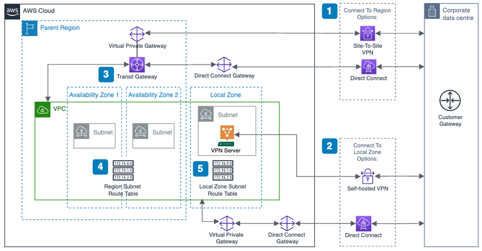
A staging S3 bucket should have specific resource policies restricting which applications and identity and access management (IAM) principals can interact with S3 objects using object attributes, such as object tags, to determine whether an object has been scanned, and what the results of that scan are. Additional guardrails are implemented using Service Control Policies (SCP) to restrict authorized IAM principals to create or modify S3 object attributes (Figure 1).

Amazon S3 antivirus and antimalware scanning architecture workflow

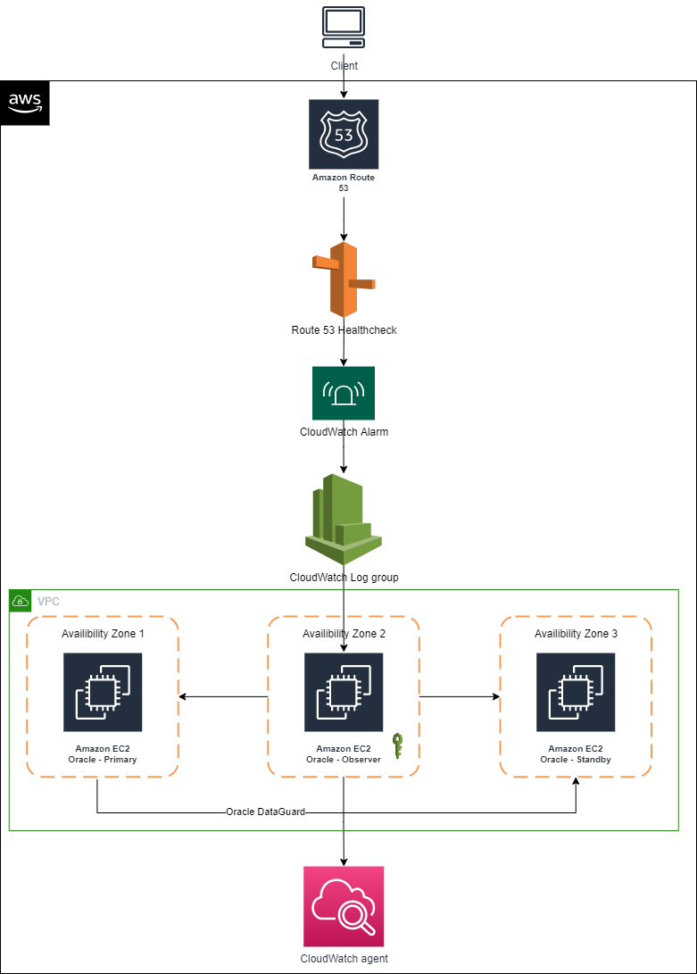
Figure 1. Amazon S3 antivirus and antimalware scanning architecture workflow

  1. The external vendor copies an object to the staging S3 bucket.
  2. The staging S3 bucket has event notifications configured and generates an event.
  3. The S3 PutObject event is sent to an Object Created Amazon Simple Queue Service (Amazon SQS) queue topic.
  4. An Amazon Elastic Compute Cloud (Amazon EC2) Auto Scaling group is configured to scale based on messages in the Object Created SQS queue.
  5. An antivirus and antimalware scanning service application on the Amazon EC2 instances takes the following actions on objects within the Object Created Amazon SQS queue:
    a. Tag the S3 object with an “In Progress” status.
    b. Get the object from the Staging S3 bucket and stores it in a local ephemeral file system.
    c. Scan the copied object using antivirus or antimalware tool.
    d. Based on the antivirus or antimalware scan results, tag the S3 object with the scan results (for example, No_Malware_Detected vs. Malware_Detected).
    e. Create and publish a payload to the Object Scanned Amazon Simple Notification Service (Amazon SNS) topic, allowing application team filtering.
    f. Delete the message from the Object Created SQS queue.
  6. Application teams are subscribed to the Object Scanned SNS topic with a filter for their application.
  7. For any objects where a virus or malware is detected, a company can use its cyber threat response team to conduct a thorough analysis and take appropriate actions.

USAA built a custom anti-virus and anti-malware scanning application using EC2 instances, using a private, hardened Amazon Machine Image (AMI). For cost-efficacy purposes, the EC2 automatic scaling event can be configured based on Object Created SQS queue depth and Service Level Objective (SLO). A serverless version of an anti-virus and anti-malware solution can be used instead of an EC2 application, depending on your specific use-case and other factors. Some important factors include antivirus and antimalware tool serverless support, resource tuning and configuration requirements, and additional AWS services to manage that could possibly result in a bottleneck. If your enterprise is going with a serverless approach, you can use open-source tools such as ClamAV using Lambda functions.

In the event of an infected object, proper guardrails and response mechanisms need to be in place. USAA teams have developed playbooks to monitor the health and performance of S3 scanning solution, as well as responding to detected virus or malware.

This cloud native, event-driven solution has benefited multiple USAA application teams who have previously requested the ability to ingest data into AWS workloads from teams outside of USAA’s AWS Organization, and allowed additional capabilities and functionality to better serve their members. To enhance this solution even further, USAA’s security team plans to incorporate additional mechanisms to find specific objects that either failed or required additional processing, without having to scan all objects in the buckets. This can be accomplished by including an additional AWS Lambda function and Amazon DynamoDB table to track object metadata as objects get added to the Object Created SQS queue for processing. The metadata could possibly include information such as S3 bucket origin, S3 object key, version ID, scan status, and the original S3 event payload to replay the event into the Object Created SQS queue. The Lambda function primarily ensures the DynamoDB table is kept up to date as objects are processed, as well as handling issues for objects that may need to be reprocessed. The DynamoDB table also has time-to-live (TTL) configured to clear records as they expire from the Staging S3 bucket.

Conclusion

In this post, we reviewed how USAA’s Public Cloud Security team facilitated collaboration and interactions with external vendors and AWS workloads securely by creating a scalable solution to scan S3 objects for virus and malware prior to releasing objects downstream. The solution uses native AWS services and can be utilized for any use-cases requiring antivirus or antimalware capabilities. Because the S3 object scanning solution uses EC2 instances, you can use your existing antivirus or antimalware enterprise tool.

Building highly resilient applications with on-premises interdependencies using AWS Local Zones

Post Syndicated from Sheila Busser original https://aws.amazon.com/blogs/compute/building-highly-resilient-applications-with-on-premises-interdependencies-using-aws-local-zones/

This blog post is written by Rachel Rui Liu, Senior Solutions Architect.

AWS Local Zones are a type of infrastructure deployment that places compute, storage, database, and other select AWS services close to large population and industry centers.

Following the successful launch of the AWS Local Zones in 16 US cities since 2019, in Feb 2022, AWS announced plans to launch new AWS Local Zones in 32 metropolitan areas in 26 countries worldwide.

With Local Zones, we’ve seen use cases in two common categories.

The first category of use cases is for workloads that require extremely low latency between end-user devices and workload servers. For example, let’s consider media content creation and real-time multiplayer gaming. For these use cases, deploying the workload to a Local Zone can help achieve down to single-digit milliseconds latency between end-user devices and the AWS infrastructure, which is ideal for a good end-user experience.

This post will focus on addressing the second category of use cases, which is commonly seen in an enterprise hybrid architecture, where customers must achieve low latency between AWS infrastructure and existing on-premises data centers.  Compared to the first category of use cases, these use cases can tolerate slightly higher latency between the end-user devices and the AWS infrastructure. However, these workloads have dependencies to these on-premises systems, so the lowest possible latency between AWS infrastructure and on-premises data centers is required for better application performance. Here are a few examples of these systems:

  • Financial services sector mainframe workloads hosted on premises serving regional customers.
  • Enterprise Active Directory hosted on premise serving cloud and on-premises workloads.
  • Enterprise applications hosted on premises processing a high volume of locally generated data.

For workloads deployed in AWS, the time taken for each interaction with components still hosted in the on-premises data center is increased by the latency. In turn, this delays responses received by the end-user. The total latency accumulates and results in suboptimal user experiences.

By deploying modernized workloads in Local Zones, you can reduce latency while continuing to access systems hosted in on-premises data centers, thereby reducing the total latency for the end-user. At the same time, you can enjoy the benefits of agility, elasticity, and security offered by AWS, and can apply the same automation, compliance, and security best practices that you’ve been familiar with in the AWS Regions.

Enterprise workload resiliency with Local Zones

While designing hybrid architectures with Local Zones, resiliency is an important consideration. You want to route traffic to the nearest Local Zone for low latency. However, when disasters happen, it’s critical to fail over to the parent Region automatically.

Let’s look at the details of hybrid architecture design based on real world deployments from different angles to understand how the architecture achieves all of the design goals.

Hybrid architecture with resilient network connectivity

The following diagram shows a high-level overview of a resilient enterprise hybrid architecture with Local Zones, where you have redundant connections between the AWS Region, the Local Zone, and the corporate data center.

resillient network connectivity

Here are a few key points with this network connectivity design:

  1. Use AWS Direct Connect or Site-to-Site VPN to connect the corporate data center and AWS Region.
  2. Use Direct Connect or self-hosted VPN to connect the corporate data center and the Local Zone. This connection will provide dedicated low-latency connectivity between the Local Zone and corporate data center.
  3. Transit Gateway is a regional service. When attaching the VPC to AWS Transit Gateway, you can only add subnets provisioned in the Region. Instances on subnets in the Local Zone can still use Transit Gateway to reach resources in the Region.
  4. For subnets provisioned in the Region, the VPC route table should be configured to route the traffic to the corporate data center via Transit Gateway.
  5. For subnets provisioned in Local Zone, the VPC route table should be configured to route the traffic to the corporate data center via the self-hosted VPN instance or Direct Connect.

Hybrid architecture with resilient workload deployment

The next examples show a public and a private facing workload.

To simplify the diagram and focus on application layer architecture, the following diagrams assume that you are using Direct Connect to connect between AWS and the on-premises data center.

Example 1: Resilient public facing workload

With a public facing workload, end-user traffic will be routed to the Local Zone. If the Local Zone is unavailable, then the traffic will be routed to the Region automatically using an Amazon Route 53 failover policy.

public facing workload resilliency
Here are the key design considerations for this architecture:

  1. Deploy the workload in the Local Zone and put the compute layer in an AWS AutoScaling Group, so that the application can scale up and down depending on volume of requests.
  2. Deploy the workload in both the Local Zone and an AWS Region, and put the compute layer into an autoscaling group. The regional deployment will act as pilot light or warm standby with minimal footprint. But it can scale out when the Local Zone is unavailable.
  3. Two Application Load Balancers (ALBs) are required: one in the Region and one in the Local Zone. Each ALB will dispatch the traffic to each workload cluster inside the autoscaling group local to it.
  4. An internet gateway is required for public facing workloads. When using a Local Zone, there’s no extra configuration needed: define a single internet gateway and attach it to the VPC.

If you want to specify an Elastic IP address to be the workload’s public endpoint, the Local Zone will have a different address pool than the Region. Noting that BYOIP is unsupported for Local Zones.

  1. Create a Route 53 DNS record with “Failover” as the routing policy.
  • For the primary record, point it to the alias of the ALB in the Local Zone. This will set Local Zone as the preferred destination for the application traffic which minimizes latency for end-users.
  • For the secondary record, point it to the alias of the ALB in the AWS Region.
  • Enable health check for the primary record. If health check against the primary record fails, which indicates that the workload deployed in the Local Zone has failed to respond, then Route 53 will automatically point to the secondary record, which is the workload deployed in the AWS Region.

Example 2: Resilient private workload

For a private workload that’s only accessible by internal users, a few extra considerations must be made to keep the traffic inside of the trusted private network.

private workload resilliency

The architecture for resilient private facing workload has the same steps as public facing workload, but with some key differences. These include:

  1. Instead of using a public hosted zone, create private hosted zones in Route 53 to respond to DNS queries for the workload.
  2. Create the primary and secondary records in Route 53 just like the public workload but referencing the private ALBs.
  3. To allow end-users onto the corporate network (within offices or connected via VPN) to resolve the workload, use the Route 53 Resolver with an inbound endpoint. This allows end-users located on-premises to resolve the records in the private hosted zone. Route 53 Resolver is designed to be integrated with an on-premises DNS server.
  4. No internet gateway is required for hosting the private workload. You might need an internet gateway in the Local Zone for other purposes: for example, to host a self-managed VPN solution to connect the Local Zone with the corporate data center.

Hosting multiple workloads

Customers who host multiple workloads in a single VPC generally must consider how to segregate those workloads. As with workloads in the AWS Region, segregation can be implemented at a subnet or VPC level.

If you want to segregate workloads at the subnet level, you can extend your existing VPC architecture by provisioning extra sets of subnets to the Local Zone.

segregate workloads at subnet level

Although not shown in the diagram, for those of you using a self-hosted VPN to connect the Local Zone with an on-premises data center, the VPN solution can be deployed in a centralized subnet.

You can continue to use security groups, network access control lists (NACLs) , and VPC route tables – just as you would in the Region to segregate the workloads.

If you want to segregate workloads at the VPC level, like many of our customers do, within the Region, inter-VPC routing is generally handled by Transit Gateway. However, in this case, it may be undesirable to send traffic to the Region to reach a subnet in another VPC that is also extended to the Local Zone.

segregate workloads at VPC level

Key considerations for this design are as follows:

  1. Direct Connect is deployed to connect the Local Zone with the corporate data center. Therefore, each VPC will have a dedicated Virtual Private Gateway provisioned to allow association with the Direct Connect Gateway.
  2. To enable inter-VPC traffic within the Local Zone, peer the two VPCs together.
  3. Create a VPC route table in VPC A. Add a route for Subnet Y where the destination is the peering link. Assign this route table to Subnet X.
  4. Create a VPC route table in VPC B. Add a route for Subnet X where the destination is the peering link. Assign this route table to Subnet Y.
  5. If necessary, add routes for on-premises networks and the transit gateway to both route tables.

This design allows traffic between subnets X and Y to stay within the Local Zone, thereby avoiding any latency from the Local Zone to the AWS Region while still permitting full connectivity to all other networks.

Conclusion

In this post, we summarized the use cases for enterprise hybrid architecture with Local Zones, and showed you:

  • Reference architectures to host workloads in Local Zones with low-latency connectivity to corporate data centers and resiliency to enable fail over to the AWS Region automatically.
  • Different design considerations for public and private facing workloads utilizing this hybrid architecture.
  • Segregation and connectivity considerations when extending this hybrid architecture to host multiple workloads.

Hopefully you will be able to follow along with these reference architectures to build and run highly resilient applications with local system interdependencies using Local Zones.

How Shiji Group created a global guest profile store on AWS

Post Syndicated from Maximilian Schellhorn original https://aws.amazon.com/blogs/architecture/how-shiji-group-created-a-global-guest-profile-store-on-aws/

Shiji Group provides global software solutions for the hospitality industry. The Shiji Enterprise Platform enables customers to manage large hotel property portfolios using software as a service (SaaS). Among functionalities such as reservations, housekeeping, finance, and integrations with external systems, the guest profile is a key aspect of the system. Besides personal information (such as name and address) and billing details, the guest profile can include room preferences and entertainment options.

A property portfolio can span multiple hotels across the globe, and each hotel location can offer better customer service by consolidating data. Once the guest gives their cross-border data processing consent (CBDPC), profile information can be shared between properties. This provides a centralized and seamless experience for the hotel guest no matter which hotel in the portfolio was chosen.

In the following blog post, you will explore the architecture of the guest profile store that replicates the profile across multiple geographic areas. We will review the single Region design first and its infrastructure components and architectural patterns. We will then show the evolution to a multi-Region architecture.

Single Region architecture with CQRS

The ability to find relevant guest profile data fast is essential in the day-to-day hospitality business. Therefore, the following architecture uses the command query responsibility segregation (CQRS) pattern to provide high scalability and rich full-text search capabilities without sacrificing performance. With CQRS, write requests (commands) are targeting a different service than read requests (queries). This allows systems to store an item (such as a profile) in a search-optimized format for serving reads, while providing a simple schema for writes.

The microservices for the guest profile architecture are operated as containers on Amazon Elastic Kubernetes Service (Amazon EKS). The write model of the guest profile is stored in an Amazon Relational Database Service (Amazon RDS) PostgreSQL database. A separate read model uses Amazon OpenSearch Service. For interservice communication, Shiji runs a self-managed Apache Kafka cluster on Amazon Elastic Compute Cloud (Amazon EC2).

The following diagram provides a walk through the single Region architecture:

Single Region architecture with CQRS

Figure 1. Single Region architecture with CQRS

  1. The front desk employee creates the Guest Profile upon first interaction with the hotel guest (name, address, billing, and room preferences).
  2. The request is routed to the Kong API Management Solution that is running in an Amazon EKS Kubernetes cluster. It acts as the single entry-point to the system. It identifies the type of request by parsing the URL and forwarding write requests to the profile-write-model-service.
  3. The service validates the request. It stores the data and ProfileCreated event in the PostgreSQL database, Amazon RDS.
  4. A change data capture (CDC) mechanism publishes the ProfileCreated event to an Apache Kafka Local Profiles topic.
  5. The profile-read-model-service subscribes to the Local Profiles topic and stores the profile in an optimized read format in Amazon OpenSearch. Whenever the hotel performs a guest profile search, results will now be provided via the profile-read-model-service.

Multi-Region networking setup

Shiji operates in multiple AWS Regions to provide low latency, regulatory requirements, and resilience across the globe. The previously presented single Region architecture can be replicated to multiple AWS Regions (eu-central-1 and ap-southeast-1, for example). Hotels with a given property portfolio that operate in the same Region can reuse the profile store of the Shiji Enterprise Platform. However, hotels that are being operated in a different AWS Region can be interconnected as well.

This is achieved by providing an AWS Transit Gateway in a separate networking account that connects the different Regions with a VPC attachment:

Multi-Region networking setup

Figure 2. Multi-Region networking setup

The account segregation provides an additional layer of flexibility to add further Regions in the future.

Multi-Region event replication

Upon first arrival, guests can choose to sign a cross-border-data processing consent (CBDPC). This permits the hotel to share the profile information globally. If accepted, the profile-write-model-service creates an additional ProfileCreated event that gets published to a GlobalProfilesEU Apache Kafka topic. This topic is accessible for subscribers in the target Region, which replicates relevant profiles into the local database as follows.

A replicator-service in the target Region (ap-souteast-1) is now able to subscribe to the GlobalProfileEU topic in (eu-central-1), via the established network connection from the previous section. It republishes the event to a local ReplicatedProfiles topic that the profile-write-model-service subscribes to and saves to the local database:

Event replication

Figure 3. Event replication

Putting it all together: The multi-Region guest profile store

The following diagram combines all the components from the previous sections. It provides an end-to-end look at the multi-Region guest profile architecture. Due to the event driven nature of the system, the architecture can be extended without changing the initial flow outlined in the single Region design.

Multi-Region guest profile architecture

Figure 4. Multi-Region guest profile architecture

  1. If the hotel guest signed a cross-border data processing consent (CBDPC), the ProfileCreated event will also be published to a Global Profiles topic.
  2. The replicator-service in the target Region (for example, ap-southeast-1) subscribes to the Global Profiles topic of the source Region (for example, eu-central-1). It then publishes the event to its local Replicated Profiles topic.
  3. The profile-write-model-service in the target Region subscribes to the Replicated Profiles topic and records the item in the Amazon RDS PostgreSQL database with information about the source Region. This will initiate the local replication similar to the single Region design, and therefore creates a consistent experience between both Regions.

Conclusion and outlook

In this blog post, we showed how Shiji built a modern multi-Region microservice architecture on AWS. You have learned about patterns such as CQRS, which provide a scalable solution for both read and write traffic. We’ve also shown what is needed to interconnect two physically separated Regions. With cross-border data processing consent (CBDPC), you have seen how the ownership of guest data can be secured and utilized. The single Region architecture already provided a solid baseline for this solution architecture. The event-driven nature of the system permitted us to add additional functionality for the final multi-Region architecture.

The ability to manage a global guest profile within the main system as well as at the property itself is a huge advantage for enterprise hotel companies. It permits hotels to deliver a unified experience to their guests no matter where the guest is within the hotel or on their journey. Food preferences, spa, room, and more, can all be managed from a single guest profile. This centralized information hasn’t been possible within the hotel’s property management system (PMS) until recently.

Visit Shiji Enterprise Platform for more information.

Adding approval notifications to EC2 Image Builder before sharing AMIs

Post Syndicated from Sheila Busser original https://aws.amazon.com/blogs/compute/adding-approval-notifications-to-ec2-image-builder-before-sharing-amis-2/

­­­­­This blog post is written by, Glenn Chia Jin Wee, Associate Cloud Architect, and Randall Han, Professional Services.

You may be required to manually validate the Amazon Machine Image (AMI) built from an Amazon Elastic Compute Cloud (Amazon EC2) Image Builder pipeline before sharing this AMI to other AWS accounts or to an AWS organization. Currently, Image Builder provides an end-to-end pipeline that automatically shares AMIs after they’ve been built.

In this post, we will walk through the steps to enable approval notifications before AMIs are shared with other AWS accounts. Image Builder supports automated image testing using test components. The recommended best practice is to automate test steps, however situations can arise where test steps become either challenging to automate or internal compliance policies mandate manual checks be conducted prior to distributing images. In such situations, having a manual approval step is useful if you would like to verify the AMI configuration before it is shared to other AWS accounts or an AWS Organization. A manual approval step reduces the potential for sharing an incorrectly configured AMI with other teams which can lead to downstream issues. This solution sends an email with a link to approve or reject the AMI. Users approve the AMI after they’ve verified that it is built according to specifications. Upon approving the AMI, the solution automatically shares it with the specified AWS accounts.

OverviewArchitecture Diagram

  1. In this solution, an Image Builder Pipeline is run that builds a Golden AMI in Account A. After the AMI is built, Image Builder publishes data about the AMI to an Amazon Simple Notification Service (Amazon SNS)
  2. The SNS Topic passes the data to an AWS Lambda function that subscribes to it.
  3. The Lambda function that subscribes to this topic retrieves the data, formats it, and then starts an SSM Automation, passing it the AMI Name and ID.
  4. The first step of the SSM Automation is a manual approval step. The SSM Automation first publishes to an SNS Topic that has an email subscription with the Approver’s email. The approver will receive the email with a URL that they can click to approve the step.
  5. The approval step defines a specific AWS Identity and Access Management (IAM) Role as an approver. This role has the minimum required permissions to approve the manual approval step. After performing manual tests on the Golden AMI, the Approver principal will assume this role.
  6. After assuming this role, the approver will click on the approval link that was sent via email. After approving the step, an AWS Lambda Function is triggered.
  7. This Lambda Function shares the Golden AMI with Account B and sends an email notifying the Target Account Recipients that the AMI has been shared.

Prerequisites

For this walkthrough, you will need the following:

  • Two AWS accounts – one to host the solution resources, and the second which receives the shared Golden AMI.
    • In the account that hosts the solution, prepare an AWS Identity and Access Management (IAM) principal with the sts:AssumeRole permission. This principal must assume the IAM Role that is listed as an approver in the Systems Manager approval step. The ARN of this IAM principal is used in the AWS CloudFormation Approver parameter, This ARN is added to the trust policy of approval IAM Role.
    • In addition, in the account hosting the solution, ensure that the IAM principal deploying the CloudFormation template has the required permissions to create the resources in the stack.
  • A new Amazon Virtual Private Cloud (Amazon VPC) will be created from the stack. Make sure that you have fewer than five VPCs in the selected Region.

Walkthrough

In this section, we will guide you through the steps required to deploy the Image Builder solution. The solution is deployed with CloudFormation.

In this scenario, we deploy the solution within the approver’s account. The approval email will be sent to a predefined email address for manual approval, before the newly created AMI is shared to target accounts.

The approver first assumes the approval IAM Role and then selects the approval link. This leads to the Systems Manager approval page. Upon approval, an email notification will be sent to the predefined target account email address, notifying the relevant stakeholders that the AMI has been successfully shared.

The high-level steps we will follow are:

  1. In Account A, deploy the provided AWS CloudFormation template. This includes an example Image Builder Pipeline, Amazon SNS topics, Lambda functions, and an SSM Automation Document.
  2. Approve the SNS subscription from your supplied email address.
  3. Run the pipeline from the Amazon EC2 Image Builder Console.
  4. [Optional] To conduct manual tests, launch an Amazon EC2 instance from the built AMI after the pipeline runs.
  5. An email will be sent to you with options to approve or reject the step. Ensure that you have assumed the IAM Role that is the approver before clicking the approval link that leads to the SSM console approval page.
  6. Upon approving the step, an AWS Lambda function shares the AMI to the Account B and also sends an email to the target account email recipients notifying them that the AMI has been shared.
  7. Log in to Account B and verify that the AMI has been shared.

Step 1: Deploy the AWS CloudFormation template

1. The CloudFormation template, template.yaml that deploys the solution can also found at this GitHub repository. Follow the instructions at the repository to deploy the stack.

Step 2: Verify your email address

  1. After running the deployment, you will receive an email prompting you to confirm the Subscription at the approver email address. Choose Confirm subscription.

SNS Topic Subscription confirmation email

  1. This leads to the following screen, which shows that your subscription is confirmed.

subscription-confirmation

  1. Repeat the previous 2 steps for the target email address.

Step 3: Run the pipeline from the Image Builder console

  1. In the Image Builder console, under Image pipelines, select the checkbox next to the Pipeline created, choose Actions, and select Run pipeline.

run-image-builder-pipeline

Note: The pipeline takes approximately 20 – 30 minutes to complete.

Step 4: [Optional] Launch an Amazon EC2 instance from the built AMI

If you have a requirement to manually validate the AMI before sharing it with other accounts or to the AWS organization an approver will launch an Amazon EC2 instance from the built AMI and conduct manual tests on the EC2 instance to make sure it is functional.

  1. In the Amazon EC2 console, under Images, choose AMIs. Validate that the AMI is created.

ami-in-account-a

  1. Follow AWS docs: Launching an EC2 instances from a custom AMI for steps on how to launch an Amazon EC2 instance from the AMI.

Step 5: Select the approval URL in the email sent

  1. When the pipeline is run successfully, you will receive another email with a URL to approve the AMI.

approval-email

  1. Before clicking on the Approve link, you must assume the IAM Role that is set as an approver for the Systems Manager step.
  2. In the CloudFormation console, choose the stack that was deployed.

cloudformation-stack

4. Choose Outputs and copy the IAM Role name.

ssm-approval-role-output

5. While logged in as the IAM Principal that has permissions to assume the approval IAM Role, follow the instructions at AWS IAM documentation for switching a role using the console to assume the approval role.
In the Switch Role page, in Role paste the name of the IAM Role that you copied in the previous step.

Note: This IAM Role was deployed with minimum permissions. Hence, seeing warning messages in the console is expected after assuming this role.

switch-role

6. Now in the approval email, select the Approve URL. This leads to the Systems Manager console. Choose Submit.

approve-console

7. After approving the manual step, the second step is executed, which shares the AMI to the target account.

automation-step-success

Step 6: Verify that the AMI is shared to Account B

  1. Log in to Account B.
  2. In the Amazon EC2 console, under Images, choose AMIs. Then, in the dropdown, choose Private images. Validate that the AMI is shared.

verify-ami-in-account-b

  1. Verify that a success email notification was sent to the target account email address provided.

target-email

Clean up

This section provides the necessary information for deleting various resources created as part of this post.

  1. Deregister the AMIs that were created and shared.
    1. Log in to Account A and follow the steps at AWS documentation: Deregister your Linux AMI.
  2. Delete the CloudFormation stack. For instructions, refer to Deleting a stack on the AWS CloudFormation console.

Conclusion

In this post, we explained how to enable approval notifications for an Image Builder pipeline before AMIs are shared to other accounts. This solution can be extended to share to more than one AWS account or even to an AWS organization. With this solution, you will be notified when new golden images are created, allowing you to verify the accuracy of their configuration before sharing them to for wider use. This reduces the possibility of sharing AMIs with misconfigurations that the written tests may not have identified.

We invite you to experiment with different AMIs created using Image Builder, and with different Image Builder components. Check out this GitHub repository for various examples that use Image Builder. Also check out this blog on Image builder integrations with EC2 Auto Scaling Instance Refresh. Let us know your questions and findings in the comments, and have fun!

Amazon EC2 Trn1 Instances for High-Performance Model Training are Now Available

Post Syndicated from Antje Barth original https://aws.amazon.com/blogs/aws/amazon-ec2-trn1-instances-for-high-performance-model-training-are-now-available/

Deep learning (DL) models have been increasing in size and complexity over the last few years, pushing the time to train from days to weeks. Training large language models the size of GPT-3 can take months, leading to an exponential growth in training cost. To reduce model training times and enable machine learning (ML) practitioners to iterate fast, AWS has been innovating across chips, servers, and data center connectivity.

At AWS re:Invent 2021, we announced the preview of Amazon EC2 Trn1 instances powered by AWS Trainium chips. AWS Trainium is optimized for high-performance deep learning training and is the second-generation ML chip built by AWS, following AWS Inferentia.

Today, I’m excited to announce that Amazon EC2 Trn1 instances are now generally available! These instances are well-suited for large-scale distributed training of complex DL models across a broad set of applications, such as natural language processing, image recognition, and more.

Compared to Amazon EC2 P4d instances, Trn1 instances deliver 1.4x the teraFLOPS for BF16 data types, 2.5x more teraFLOPS for TF32 data types, 5x the teraFLOPS for FP32 data types, 4x inter-node network bandwidth, and up to 50 percent cost-to-train savings. Trn1 instances can be deployed in EC2 UltraClusters that serve as powerful supercomputers to rapidly train complex deep learning models. I’ll share more details on EC2 UltraClusters later in this blog post.

New Trn1 Instance Highlights
Trn1 instances are available today in two sizes and are powered by up to 16 AWS Trainium chips with 128 vCPUs. They provide high-performance networking and storage to support efficient data and model parallelism, popular strategies for distributed training.

Trn1 instances offer up to 512 GB of high-bandwidth memory, deliver up to 3.4 petaFLOPS of TF32/FP16/BF16 compute power, and feature an ultra-high-speed NeuronLink interconnect between chips. NeuronLink helps avoid communication bottlenecks when scaling workloads across multiple Trainium chips.

Trn1 instances are also the first EC2 instances to enable up to 800 Gbps of Elastic Fabric Adapter (EFA) network bandwidth for high-throughput network communication. This second generation EFA delivers lower latency and up to 2x more network bandwidth compared to the previous generation. Trn1 instances also come with up to 8 TB of local NVMe SSD storage for ultra-fast access to large datasets.

The following table lists the sizes and specs of Trn1 instances in detail.

Instance Name
vCPUs AWS Trainium Chips Accelerator Memory NeuronLink Instance Memory Instance Networking Local Instance Storage
trn1.2xlarge 8 1 32 GB N/A 32 GB Up to 12.5 Gbps 1x 500 GB NVMe
trn1.32xlarge 128 16 512 GB Supported 512 GB 800 Gbps 4x 2 TB NVMe

Trn1 EC2 UltraClusters
For large-scale model training, Trn1 instances integrate with Amazon FSx for Lustre high-performance storage and are deployed in EC2 UltraClusters. EC2 UltraClusters are hyperscale clusters interconnected with a non-blocking petabit-scale network. This gives you on-demand access to a supercomputer to cut model training time for large and complex models from months to weeks or even days.

Amazon EC2 Trn1 UltraCluster

AWS Trainium Innovation
AWS Trainium chips include specific scalar, vector, and tensor engines that are purpose-built for deep learning algorithms. This ensures higher chip utilization as compared to other architectures, resulting in higher performance.

Here is a short summary of additional hardware innovations:

  • Data Types: AWS Trainium supports a wide range of data types, including FP32, TF32, BF16, FP16, and UINT8, so you can choose the most suitable data type for your workloads. It also supports a new, configurable FP8 (cFP8) data type, which is especially relevant for large models because it reduces the memory footprint and I/O requirements of the model.
  • Hardware-Optimized Stochastic Rounding: Stochastic rounding achieves close to FP32-level accuracy with faster BF16-level performance when you enable auto-casting from FP32 to BF16 data types. Stochastic rounding is a different way of rounding floating-point numbers, which is more suitable for machine learning workloads versus the commonly used Round Nearest Even rounding. By setting the environment variable NEURON_RT_STOCHASTIC_ROUNDING_EN=1 to use stochastic rounding, you can train a model up to 30 percent faster.
  • Custom Operators, Dynamic Tensor Shapes: AWS Trainium also supports custom operators written in C++ and dynamic tensor shapes. Dynamic tensor shapes are key for models with unknown input tensor sizes, such as models processing text.

AWS Trainium shares the same AWS Neuron SDK as AWS Inferentia, making it easy for everyone who is already using AWS Inferentia to get started with AWS Trainium.

For model training, the Neuron SDK consists of a compiler, framework extensions, a runtime library, and developer tools. The Neuron plugin natively integrates with popular ML frameworks, such as PyTorch and TensorFlow.

The AWS Neuron SDK supports just-in-time (JIT) compilation, in addition to ahead-of-time (AOT) compilation, to speed up model compilation, and Eager Debug Mode, for a step-by-step execution.

To compile and run your model on AWS Trainium, you need to change only a few lines of code in your training script. You don’t need to tweak your model or think about data type conversion.

Get Started with Trn1 Instances
In this example, I train a PyTorch model on an EC2 Trn1 instance using the available PyTorch Neuron packages. PyTorch Neuron is based on the PyTorch XLA software package and enables conversion of PyTorch operations to AWS Trainium instructions.

Each AWS Trainium chip includes two NeuronCore accelerators, which are the main neural network compute units. With only a few changes to your training code, you can train your PyTorch model on AWS Trainium NeuronCores.

SSH into the Trn1 instance and activate a Python virtual environment that includes the PyTorch Neuron packages. If you’re using a Neuron-provided AMI, you can activate the preinstalled environment by running the following command:

source aws_neuron_venv_pytorch_p36/bin/activate

Before you can run your training script, you need to make a few modifications. On Trn1 instances, the default XLA device should be mapped to a NeuronCore.

Let’s start by adding the PyTorch XLA imports to your training script:

import torch, torch_xla
import torch_xla.core.xla_model as xm

Then, place your model and tensors onto an XLA device:

model.to(xm.xla_device())
tensor.to(xm.xla_device())

When the model is moved to the XLA device (NeuronCore), subsequent operations on the model are recorded for later execution. This is XLA’s lazy execution which is different from PyTorch’s eager execution. Within the training loop, you have to mark the graph to be optimized and run on the XLA device using xm.mark_step(). Without this mark, XLA cannot determine where the graph ends.

...
for data, target in train_loader:
	output = model(data)
	loss = loss_fn(output, target)
	loss.backward()
	optimizer.step()
	xm.mark_step()
...

You can now run your training script using torchrun <my_training_script>.py.

When running the training script, you can configure the number of NeuronCores to use for training by using torchrun –nproc_per_node.

For example, to run a multi-worker data parallel model training on all 32 NeuronCores in one trn1.32xlarge instance, run torchrun --nproc_per_node=32 <my_training_script>.py.

Data parallel is a strategy for distributed training that allows you to replicate your script across multiple workers, with each worker processing a portion of the training dataset. The workers then share their result with each other.

For more details on supported ML frameworks, model types, and how to prepare your model training script for large-scale distributed training across trn1.32xlarge instances, have a look at the AWS Neuron SDK documentation.

Profiling Tools
Let’s have a quick look at useful tools to keep track of your ML experiments and profile Trn1 instance resource consumption. Neuron integrates with TensorBoard to track and visualize your model training metrics.

AWS Neuron SDK TensorBoard integration

On the Trn1 instance, you can use the neuron-ls command to describe the number of Neuron devices present in the system, along with the associated NeuronCore count, memory, connectivity/topology, PCI device information, and the Python process that currently has ownership of the NeuronCores:

AWS Neuron SDK neuron-ls command

Similarly, you can use the neuron-top command to see a high-level view of the Neuron environment. This shows the utilization of each of the NeuronCores, any models that are currently loaded onto one or more NeuronCores, process IDs for any processes that are using the Neuron runtime, and basic system statistics relating to vCPU and memory usage.

AWS Neuron SDK neuron-top command

Available Now
You can launch Trn1 instances today in the AWS US East (N. Virginia) and US West (Oregon) Regions as On-Demand, Reserved, and Spot Instances or as part of a Savings Plan. As usual with Amazon EC2, you pay only for what you use. For more information, see Amazon EC2 pricing.

Trn1 instances can be deployed using AWS Deep Learning AMIs, and container images are available via managed services such as Amazon SageMaker, Amazon Elastic Kubernetes Service (Amazon EKS), Amazon Elastic Container Service (Amazon ECS), and AWS ParallelCluster.

To learn more, visit our Amazon EC2 Trn1 instances page, and please send feedback to AWS re:Post for EC2 or through your usual AWS Support contacts.

— Antje

Best Practices for Hosting Regulated Gaming Workloads in AWS Local Zones and on AWS Outposts

Post Syndicated from Sheila Busser original https://aws.amazon.com/blogs/compute/best-practices-for-hosting-regulated-gaming-workloads-in-aws-local-zones-and-on-aws-outposts/

This blog post is written by Shiv Bhatt, Manthan Raval, and Pawan Matta, who are Senior Solutions Architects with AWS.

Many industries are subject to regulations that are created to protect the interests of the various stakeholders. For some industries, the specific details of the regulatory requirements influence not only the organization’s operations, but also their decisions for adopting new technology. In this post, we highlight the workload residency challenges that you may encounter when you deploy regulated gaming workloads, and how AWS Local Zones and AWS Outposts can help you address those challenges.

Regulated gaming workloads and residency requirements

A regulated gaming workload is a type of workload that’s subject to federal, state, local, or tribal laws related to the regulation of gambling and real money gaming. Examples of these workloads include sports betting, horse racing, casino, poker, lottery, bingo, and fantasy sports. The operators provide gamers with access to these workloads through online and land-based channels, and they’re required to follow various regulations required in their jurisdiction. Some regulations define specific workload residency requirements, and depending on the regulatory agency, the regulations could require that workloads be hosted within a specific city, state, province, or country. For example, in the United States, different state and tribal regulatory agencies dictate whether and where gaming operations are legal in a state, and who can operate. The agencies grant licenses to the operators of regulated gaming workloads, which then govern who can operate within the state, and sometimes, specifically where these workloads can be hosted. In addition, federal legislation can also constrain how regulated gaming workloads can be operated. For example, the United States Federal Wire Act makes it illegal to facilitate bets or wagers on sporting events across state lines. This regulation requires that operators make sure that users who place bets in a specific state are also within the borders of that state.

Benefits of using AWS edge infrastructure with regulated gaming workloads

The use of AWS edge infrastructure, specifically Local Zones and Outposts to host a regulated gaming workload, can help you meet workload residency requirements. You can manage Local Zones and Outposts by using the AWS Management Console or by using control plane API operations, which lets you seamlessly consume compute, storage, and other AWS services.

Local Zones

Local Zones are a type of AWS infrastructure deployment that place compute, storage, database, and other select services closer to large population, industry, and IT centers. Like AWS Regions, Local Zones enable you to innovate more quickly and bring new products to market sooner without having to worry about hardware and data center space procurement, capacity planning, and other forms of undifferentiated heavy-lifting. Local Zones have their own connections to the internet, and support AWS Direct Connect, so that workloads hosted in the Local Zone can serve local end-users with very low-latency communications. Local Zones are by default connected to a parent Region via Amazon’s redundant and high-bandwidth private network. This lets you extend Amazon Virtual Private Cloud (Amazon VPC) in the AWS Region to Local Zones. Furthermore, this provides applications hosted in AWS Local Zones with fast, secure, and seamless access to the broader portfolio of AWS services in the AWS Region. You can see the full list of AWS services supported in Local Zones on the AWS Local Zones features page.

You can start using Local Zones right away by enabling them in your AWS account. There are no setup fees, and as with the AWS Region, you pay only for the services that you use. There are three ways to pay for Amazon Elastic Compute Cloud (Amazon EC2) instances in Local Zones: On-Demand, Savings Plans, and Spot Instances. See the full list of cities where Local Zones are available on the Local Zones locations page.

Outposts

Outposts is a family of fully-managed solutions that deliver AWS infrastructure and services to most customer data center locations for a consistent hybrid experience. For a full list of countries and territories where Outposts is available, see the Outposts rack FAQs and Outposts servers FAQs. Outposts is available in various form factors, from 1U and 2U Outposts servers to 42U Outposts racks, and multiple rack deployments. To learn more about specific configuration options and pricing, see Outposts rack and Outposts servers.

You configure Outposts to work with a specific AWS Region using AWS Direct Connect or an internet connection, which lets you extend Amazon VPC in the AWS Region to Outposts. Like Local Zones, this provides applications hosted on Outposts with fast, secure, and seamless access to the broader portfolio of AWS services in the AWS Region. See the full list of AWS services supported on Outposts rack and on Outposts servers.

Choosing between AWS Regions, Local Zones, and Outposts

When you build and deploy a regulated gaming workload, you must assess the residency requirements carefully to make sure that your workload complies with regulations. As you make your assessment, we recommend that you consider separating your regulated gaming workload into regulated and non-regulated components. For example, for a sports betting workload, the regulated components might include sportsbook operation, and account and wallet management, while non-regulated components might include marketing, the odds engine, and responsible gaming. In describing the following scenarios, it’s assumed that regulated and non-regulated components must be fault-tolerant.

For hosting the non-regulated components of your regulated gaming workload, we recommend that you consider using an AWS Region instead of a Local Zone or Outpost. An AWS Region offers higher availability, larger scale, and a broader selection of AWS services.

For hosting regulated components, the type of AWS infrastructure that you choose will depend on which of the following scenarios applies to your situation:

  1. Scenario one: An AWS Region is available in your jurisdiction and local regulators have approved the use of cloud services for your regulated gaming workload.
  2. Scenario two: An AWS Region isn’t available in your jurisdiction, but a Local Zone is available, and local regulators have approved the use of cloud services for your regulated gaming workload.
  3. Scenario three: An AWS Region or Local Zone isn’t available in your jurisdiction, or local regulators haven’t approved the use of cloud services for your regulated gaming workload, but Outposts is available.

Let’s look at each of these scenarios in detail.

Scenario one: Use an AWS Region for regulated components

When local regulators have approved the use of cloud services for regulated gaming workloads, and an AWS Region is available in your jurisdiction, consider using an AWS Region rather than a Local Zone and Outpost. For example, in the United States, the State of Ohio has announced that it will permit regulated gaming workloads to be deployed in the cloud on infrastructure located within the state when sports betting goes live in January 2023. By using the US East (Ohio) Region, operators in the state don’t need to procure and manage physical infrastructure and data center space. Instead, they can use various compute, storage, database, analytics, and artificial intelligence/machine learning (AI/ML) services that are readily available in the AWS Region. You can host a regulated gaming workload entirely in a single AWS Region, which includes Availability Zones (AZs) – multiple, isolated locations within each AWS Region. By deploying your workload redundantly across at least two AZs, you can help make sure of the high availability, as shown in the following figure.

AWS Region hosting regulated and non-regulated components

Scenario two: Use a Local Zone for regulated components

A second scenario might be that local regulators have approved the use of cloud services for regulated gaming workloads, and an AWS Region isn’t available in your jurisdiction, but a Local Zone is available. In this scenario, consider using a Local Zone rather than Outposts. A Local Zone can support more elasticity in a more cost-effective way than Outposts can. However, you might also consider using a Local Zone and Outposts together to increase availability and scalability for regulated components. Let’s consider the State of Illinois, in the United States, which allows regulated gaming workloads to be deployed in the cloud, if workload residency requirements are met. Operators in this state can host regulated components in a Local Zone in Chicago, and they can also use Outposts in their data center in the same state, for high availability and disaster recovery, as shown in the following figure.

Route ingress gaming traffic through an AWS Region hosting non-regulated components, with a Local Zone and Outposts hosting regulated components

Scenario three: Use of Outposts for regulated components

When local regulators haven’t approved the use of cloud services for regulated gaming workloads, or when an AWS Region or Local Zone isn’t available in your jurisdiction, you can still choose to host your regulated gaming workloads on Outposts for a consistent cloud experience, if Outposts is available in your jurisdiction. If you choose to use Outposts, then note that as part of the shared responsibility model, customers are responsible for attesting to physical security and access controls around the Outpost, as well as environmental requirements for the facility, networking, and power. Use of Outposts requires you to procure and manage the data center within the city, state, province, or country boundary (as required by local regulations) that may be suitable to host regulated components, depending on the jurisdiction. Furthermore, you should procure and configure supported network connections between Outposts and the parent AWS Region. During the Outposts ordering process, you should account for the compute and network capacity required to support the peak load and availability design.

For a higher availability level, you should consider procuring and deploying two or more Outposts racks or Outposts servers in a data center. You might also consider deploying redundant network paths between Outposts and the parent AWS Region. However, depending on your business service level agreement (SLA) for regulated gaming workload, you might choose to spread Outposts racks across two or more isolated data centers within the same regulated boundary, as shown in the following figure.

Route ingress gaming traffic through an AWS Region hosting non-regulated components, with an Outposts hosting regulated components

Options to route ingress gaming traffic

You have two options to route ingress gaming traffic coming into your regulated and non-regulated components when you deploy the configurations that we described previously in Scenarios two and three. Your gaming traffic can come through to the AWS Region, or through the Local Zones or Outposts. Note that the benefits that we mentioned previously around selecting the AWS Region for deploying regulated and non-regulated components are the same when you select an ingress route.

Let’s discuss the benefits and trade offs for each of these options.

Option one: Route ingress gaming traffic through an AWS Region

If you choose to route ingress gaming traffic through an AWS Region, your regulated gaming workloads benefit from access to the wide range of tools, services, and capacity available in the AWS Region. For example, native AWS security services, like AWS WAF and AWS Shield, which provide protection against DDoS attacks, are currently only available in AWS Regions. Only traffic that you route into your workload through an AWS Region benefits from these services.

If you route gaming traffic through an AWS Region, and non-regulated components are hosted in an AWS Region, then traffic has a direct path to non-regulated components. In addition, gaming traffic destined to regulated components, hosted in a Local Zone and on Outposts, can be routed through your non-regulated components and a few native AWS services in the AWS Region, as shown in Figure 2.

Option two: Route ingress gaming traffic through a Local Zone or Outposts

Choosing to route ingress gaming traffic through a Local Zone or Outposts requires careful planning to make sure that tools, services, and capacity are available in that jurisdiction, as shown in the following figure. In addition, consider how choosing this route will influence the pillars of the AWS Well-Architected Framework. This route might require deploying and managing most of your non-regulated components in a Local Zone or on Outposts as well, including native AWS services that aren’t available in Local Zones or on Outposts. If you plan to implement this topology, then we recommend that you consider using AWS Partner solutions to replace the native AWS services that aren’t available in Local Zones or Outposts.

Route ingress gaming traffic through a Local Zone and Outposts that are hosting regulated and non-regulated components, with an AWS Region hosting limited non-regulated components

Conclusion

If you’re building regulated gaming workloads, then you might have to follow strict workload residency and availability requirements. In this post, we’ve highlighted how Local Zones and Outposts can help you meet these workload residency requirements by bringing AWS services closer to where they’re needed. We also discussed the benefits of using AWS Regions in compliment to the AWS edge infrastructure, and several reliability and cost design considerations.

Although this post provides information to consider when making choices about using AWS for regulated gaming workloads, you’re ultimately responsible for maintaining compliance with the gaming regulations and laws in your jurisdiction. You’re in the best position to determine and maintain ultimate responsibility for determining whether activities are legal, including evaluating the jurisdiction of the activities, how activities are made available, and whether specific technologies or services are required to make sure of compliance with the applicable law. You should always review these regulations and laws before you deploy regulated gaming workloads on AWS.

How Launchmetrics improves fashion brands performance using Amazon EC2 Spot Instances

Post Syndicated from Ivo Pinto original https://aws.amazon.com/blogs/architecture/how-launchmetrics-improves-fashion-brands-performance-using-amazon-ec2-spot-instances/

Launchmetrics offers its Brand Performance Cloud tools and intelligence to help fashion, luxury, and beauty retail executives optimize their global strategy. Launchmetrics initially operated their whole infrastructure on-premises; however, they wanted to scale their data ingestion while simultaneously providing improved and faster insights for their clients. These business needs led them to build their architecture in AWS cloud.

In this blog post, we explain how Launchmetrics’ uses Amazon Web Services (AWS) to crawl the web for online social and print media. Using the data gathered, Launchmetrics is able to provide prescriptive analytics and insights to their clients. As a result, clients can understand their brand’s momentum and interact with their audience, successfully launching their products.

Architecture overview

Launchmetrics’ platform architecture is represented in Figure 1 and composed of three tiers:

  1. Crawl
  2. Data Persistence
  3. Processing
Launchmetrics backend architecture

Figure 1. Launchmetrics backend architecture

The Crawl tier is composed of several Amazon Elastic Compute Cloud (Amazon EC2) Spot Instances launched via Auto Scaling groups. Spot Instances take advantage of unused Amazon EC2 capacity at a discounted rate compared with On-Demand Instances, which are compute instances that are billed per-hour or -second with no long-term commitments. Launchmetrics heavily leverages Spot Instances. The Crawl tier is responsible for retrieving, processing, and storing data from several media sources (represented in Figure 1 with the number 1).

The Data Persistence tier consists of two components: Amazon Kinesis Data Streams and Amazon Simple Queue Service (Amazon SQS). Kinesis Data Streams stores data that the Crawl tier collects, while Amazon SQS stores the metadata of the whole process. In this context, metadata helps Launchmetrics gain insight into when the data is collected and if it has started processing. This is key information if a Spot Instance is interrupted, which we will dive deeper into later.

The third tier, Processing, also makes use of Spot Instances and is responsible for pulling data from the Data Persistence tier (represented in Figure 1 with the number 2). It then applies proprietary algorithms, both analytics and machine learning models, to create consumer insights. These insights are stored in a data layer (not depicted) that consists of an Amazon Aurora cluster and an Amazon OpenSearch Service cluster.

By having this separation of tiers, Launchmetrics is able to use a decoupled architecture, where each component can scale independently and is more reliable. Both the Crawl and the Data Processing tiers use Spot Instances for up to 90% of their capacity.

Data processing using EC2 Spot Instances

When Launchmetrics decided to migrate their workloads to the AWS cloud, Spot Instances were one of the main drivers. As Spot Instances offer large discounts without commitment, Launchmetrics was able to track more than 1200 brands, translating to 1+ billion end users. Daily, this represents tracking upwards of 500k influencer profiles, 8 million documents, and around 70 million social media comments.

Aside from the cost-savings with Spot Instances, Launchmetrics incurred collateral benefits in terms of architecture design: building stateless, decoupled, elastic, and fault-tolerant applications. In turn, their stack architecture became more loosely coupled, as well.

All Launchmetrics Auto Scaling groups have the following configuration:

  • Spot allocation strategy: cost-optimized
  • Capacity rebalance: true
  • Three availability zones
  • A diversified list of instance types

By using Auto Scaling groups, Launchmetrics is able to scale worker instances depending on how many items they have in the SQS queue, increasing the instance efficiency. Data processing workloads like the ones Launchmetrics’ platform have, are an exemplary use of multiple instance types, such as M5, M5a, C5, and C5a. When adopting Spot Instances, Launchmetrics considered other instance types to have access to spare capacity. As a result, Launchmetrics found out that workload’s performance improved, as they use instances with more resources at a lower cost.

By decoupling their data processing workload using SQS queues, processes are stopped when an interruption arrives. As the Auto Scaling group launches a replacement Spot Instance, clients are not impacted and data is not lost. All processes go through a data checkpoint, where a new Spot Instance resumes processing any pending data. Spot Instances have resulted in a reduction of up to 75% of related operational costs.

To increase confidence in their ability to deal with Spot interruptions and service disruptions, Launchmetrics is exploring using AWS Fault Injection Simulator to simulate faults on their architecture, like a Spot interruption. Learn more about how this service works on the AWS Fault Injection Simulator now supports Spot Interruptions launch page.

Reporting data insights

After processing data from different media sources, AWS aided Launchmetrics in producing higher quality data insights, faster: the previous on-premises architecture had a time range of 5-6 minutes to run, whereas the AWS-driven architecture takes less than 1 minute.

This is made possible by elasticity and availability compute capacity that Amazon EC2 provides compared with an on-premises static fleet. Furthermore, offloading some management and operational tasks to AWS by using AWS managed services, such as Amazon Aurora or Amazon OpenSearch Service, Launchmetrics can focus on their core business and improve proprietary solutions rather than use that time in undifferentiated activities.

Building continuous delivery pipelines

Let’s discuss how Launchmetrics makes changes to their software with so many components.

Both of their computing tiers, Crawl and Processing, consist of standalone EC2 instances launched via Auto Scaling groups and EC2 instances that are part of an Amazon Elastic Container Service (Amazon ECS) cluster. Currently, 70% of Launchmetrics workloads are still running with Auto Scaling groups, while 30% are containerized and run on Amazon ECS. This is important because for each of these workload groups, the deployment process is different.

For workloads that run on Auto Scaling groups, they use an AWS CodePipeline to orchestrate the whole process, which includes:

I.  Creating a new Amazon Machine Image (AMI) using AWS CodeBuild
II. Deploying the newly built AMI using Terraform in CodeBuild

For containerized workloads that run on Amazon ECS, Launchmetrics also uses a CodePipeline to orchestrate the process by:

III. Creating a new container image, and storing it in Amazon Elastic Container Registry
IV. Changing the container image in the task definition, and updating the Amazon ECS service using CodeBuild

Conclusion

In this blog post, we explored how Launchmetrics is using EC2 Spot Instances to reduce costs while producing high-quality data insights for their clients. We also demonstrated how decoupling an architecture is important for handling interruptions and why following Spot Instance best practices can grant access to more spare capacity.

Using this architecture, Launchmetrics produced faster, data-driven insights for their clients and increased their capacity to innovate. They are continuing to containerize their applications and are projected to have 100% of their workloads running on Amazon ECS with Spot Instances by the end of 2023.

To learn more about handling EC2 Spot Instance interruptions, visit the AWS Best practices for handling EC2 Spot Instance interruptions blog post. Likewise, if you are interested in learning more about AWS Fault Injection Simulator and how it can benefit your architecture, read Increase your e-commerce website reliability using chaos engineering and AWS Fault Injection Simulator.

Let’s Architect! Architecting with custom chips and accelerators

Post Syndicated from Luca Mezzalira original https://aws.amazon.com/blogs/architecture/lets-architect-custom-chips-and-accelerators/

It’s hard to imagine a world without computer chips. They are at the heart of the devices that we use to work and play every day. Currently, Amazon Web Services (AWS) is offering customers the next generation of computer chip, with lower cost, higher performance, and a reduced carbon footprint.

This edition of Let’s Architect! focuses on custom computer chips, accelerators, and technologies developed by AWS, such as AWS Nitro System, custom-designed Arm-based AWS Graviton processors that support data-intensive workloads, as well as AWS Trainium, and AWS Inferentia chips optimized for machine learning training and inference.

In this post, we discuss these new AWS technologies, their main characteristics, and how to take advantage of them in your architecture.

Deliver high performance ML inference with AWS Inferentia

As Deep Learning models become increasingly large and complex, the training cost for these models increases, as well as the inference time for serving.

With AWS Inferentia, machine learning practitioners can deploy complex neural-network models that are built and trained on popular frameworks, such as Tensorflow, PyTorch, and MXNet on AWS Inferentia-based Amazon EC2 Inf1 instances.

This video introduces you to the main concepts of AWS Inferentia, a service designed to reduce both cost and latency for inference. To speed up inference, AWS Inferentia: selects and shares a model across multiple chips, places pieces inside the on-chip cache, then streams the data via pipeline for low-latency predictions.

Presenters discuss through the structure of the chip, software considerations, as well as anecdotes from the Amazon Alexa team, who uses AWS Inferentia to serve predictions. If you want to learn more about high throughput coupled with low latency, explore Achieve 12x higher throughput and lowest latency for PyTorch Natural Language Processing applications out-of-the-box on AWS Inferentia on the AWS Machine Learning Blog.

AWS Inferentia shares a model across different chips to speed up inference

AWS Inferentia shares a model across different chips to speed up inference

AWS Lambda Functions Powered by AWS Graviton2 Processor – Run Your Functions on Arm and Get Up to 34% Better Price Performance

AWS Lambda is a serverless, event-driven compute service that enables code to run from virtually any type of application or backend service, without provisioning or managing servers. Lambda uses a high-availability compute infrastructure and performs all of the administration of the compute resources, including server- and operating-system maintenance, capacity-provisioning, and automatic scaling and logging.

AWS Graviton processors are designed to deliver the best price and performance for cloud workloads. AWS Graviton3 processors are the latest in the AWS Graviton processor family and provide up to: 25% increased compute performance, two-times higher floating-point performance, and two-times faster cryptographic workload performance compared with AWS Graviton2 processors. This means you can migrate AWS Lambda functions to Graviton in minutes, plus get as much as 19% improved performance at approximately 20% lower cost (compared with x86).

Comparison between x86 and Arm/Graviton2 results for the AWS Lambda function computing prime numbers

Comparison between x86 and Arm/Graviton2 results for the AWS Lambda function computing prime numbers (click to enlarge)

Powering next-gen Amazon EC2: Deep dive on the Nitro System

The AWS Nitro System is a collection of building-block technologies that includes AWS-built hardware offload and security components. It is powering the next generation of Amazon EC2 instances, with a broadening selection of compute, storage, memory, and networking options.

In this session, dive deep into the Nitro System, reviewing its design and architecture, exploring new innovations to the Nitro platform, and understanding how it allows for fasting innovation and increased security while reducing costs.

Traditionally, hypervisors protect the physical hardware and bios; virtualize the CPU, storage, networking; and provide a rich set of management capabilities. With the AWS Nitro System, AWS breaks apart those functions and offloads them to dedicated hardware and software.

AWS Nitro System separates functions and offloads them to dedicated hardware and software, in place of a traditional hypervisor

AWS Nitro System separates functions and offloads them to dedicated hardware and software, in place of a traditional hypervisor

How Amazon migrated a large ecommerce platform to AWS Graviton

In this re:Invent 2021 session, we learn about the benefits Amazon’s ecommerce Datapath platform has realized with AWS Graviton.

With a range of 25%-40% performance gains across 53,000 Amazon EC2 instances worldwide for Prime Day 2021, the Datapath team is lowering their internal costs with AWS Graviton’s improved price performance. Explore the software updates that were required to achieve this and the testing approach used to optimize and validate the deployments. Finally, learn about the Datapath team’s migration approach that was used for their production deployment.

AWS Graviton2: core components

AWS Graviton2: core components

See you next time!

Thanks for exploring custom computer chips, accelerators, and technologies developed by AWS. Join us in a couple of weeks when we talk more about architectures and the daily challenges faced while working with distributed systems.

Other posts in this series

Looking for more architecture content?

AWS Architecture Center provides reference architecture diagrams, vetted architecture solutions, Well-Architected best practices, patterns, icons, and more!

AWS Week in Review – September 19, 2022

Post Syndicated from Jeff Barr original https://aws.amazon.com/blogs/aws/aws-week-in-review-september-19-2022/

Things are heating up in Seattle, with preparation for AWS re:Invent 2022 well underway. Later this month the entire News Blog team will participate in our now-legendary “speed storming” event. Over the course of three or four days, each of the AWS service teams with a launch in the works for re:Invent will give us an overview and share their PRFAQ (Press Release + FAQ) with us. After the meetings conclude, we’ll divvy up the launches and get to work on our blog posts!

Last Week’s Launches
Here are some of the launches that caught my eye last week:

Amazon Lex Visual Conversation Builder – This new tool makes bot design easier than ever. You get a complete view of the conversation in one place, and you can manage complex conversations that have dynamic paths. To learn more and see the builder in action, read Announcing Visual Conversation Builder for Amazon Lex on the AWS Machine Learning Blog.

AWS Config Conformance Pack Price Reduction – We have reduced the price for evaluation of AWS Config Conformance Packs by up to 58%. These packs contain AWS Config rules and remediation actions that can be deployed as a single entity in account and a region, or across an entire organization. The price reduction took effect September 14, 2022; it lowers the cost per evaluation and decreases the number of evaluations needed to reach each pricing tier.

CDK (Cloud Development Kit) Tree View – The AWS CloudFormation console now includes a Constructs tree view that automatically organizes the resources that were synthesized by AWS CDK constructs. The top level of the tree view includes the named constructs and the second level includes all of the resources generated by the named construct. Read the What’s New to learn more!

AWS Incident Detection and ResponseAWS Enterprise Support customers now have access to proactive monitoring and incident management for selected workloads running on AWS. As part of the onboarding process, AWS experts review workloads for reliability and operational excellence, and work with the customer to identify critical metrics and associated alarms. Incident Management Engineers then monitor the workloads, detect critical incidents, and initiate a call bridge to accelerate recovery. Read the AWS Incident Detection and Response page and the What’s New to learn more.

ECS Cluster Scale-In Speed – Auto-Scaled ECS clusters can now scale-in (reduce capacity) faster than ever before. Previously, each scale-in would reduce the capacity within an Auto Scaling Group (ASG) by 5% at a time. Now, capacity can be reduced by up to 50%. This change makes scaling more responsive to workload changes while still maintaining availability for spiky traffic patterns. Read Faster Scaling-In for Amazon ECS Cluster Auto Scaling and the What’s New to learn more.

AWS Outposts Rack Networking – AWS Outposts racks now support local gateway ingress routing to redirect incoming traffic to an Elastic Network Interface (ENI) attached to an EC2 instance before traffic reaches workloads running on the Outpost; read Deploying Local Gateway Ingress Routing on AWS Outposts to learn more. Outposts racks now also support direct VPC routing to simplify the process of communicating with your on-premises network; read the What’s New to learn more.

Amazon SWF Console Experience Updated – The new console experience for Amazon Simple Workflow Service (SWF) gives you better visibility of your SWF domains along with additional information about your workflow executions and events. You can efficiently manage high-volume workloads and quickly find the detailed information that helps you to operate at peak efficiency. Read the What’s New to learn more.

Dynamic Intermediate Certificate Authorities – According to a post on the AWS Security Blog, public certificates issued through AWS Certificate Manager (ACM) will soon (October 11, 2022) be issued from one of several intermediate certificate authorities managed by Amazon. This change will be transparent to most customers and applications, except those that make use of certificate pinning. In some cases, older browsers will need to be updated in order to properly trust the Amazon Trust Services CAs.

X in Y – We launched existing AWS services and instance types in additional regions:

Other AWS News
AWS Open Source – Check out Installment #127 of the AWS Open Source News and Updates Newsletter to learn about new tools for AWS CloudFormation, AWS Lambda, Terraform / EKS, AWS Step Functions, AWS Identity and Access Management (IAM), and more.

New Case Study – Read this new case study to learn how the Deep Data Research Computing Center at Stanford University is creating tools designed to bridge the gap between biology and computer science in order to help researchers in precision medicine deliver tangible medical solutions.

Application Management – The AWS DevOps Blog showed you how to Implement Long-Running Deployments with AWS CloudFormation Custom Resources Using AWS Step Functions.

Architecture – The AWS Architecture Blog showed you how to Maintain Visibility Over the Use of Cloud Architecture Patterns.

Big Data – The AWS Big Data Blog showed you how to Optimize Amazon EMR Costs for Legacy and Spark Workloads.

Migration – In a two-part series on the AWS Compute Blog, Marcia showed you how to Lift and Shift a Web Application to AWS Serverless (Part 1, Part 2).

Mobile – The AWS Mobile Blog showed you how to Build Your Own Application for Route Optimization and Tracking using AWS Amplify and Amazon Location Service.

Security – The AWS Security Blog listed 10 Reasons to Import a Certificate into AWS Certificate Manager and 154 AWS Services that have achieved HITRUST Certificiation.

Training and Certification – The AWS Training and Certification Blog talked about The Value of Data and Pursuing the AWS Certified Data Analytics – Specialty Certification.

Containers – The AWS Containers Blog encouraged you to Achieve Consistent Application-Level Tagging for Cost Tracking in AWS.

Upcoming AWS Events
Check your calendar and sign up for an AWS event in your locale:

AWS Summits – Come together to connect, collaborate, and learn about AWS. Registration is open for the following in-person AWS Summits: Mexico City (September 21–22), Bogotá (October 4), and Singapore (October 6).

AWS Community DaysAWS Community Day events are community-led conferences to share and learn with one another. In September, the AWS community in the US will run events in Arlington, Virginia (September 30). In Europe, Community Day events will be held in October. Join us in Amersfoort, Netherlands (October 3), Warsaw, Poland (October 14), and Dresden, Germany (October 19).

AWS Fest – This third-party event will feature AWS influencers, community heroes, industry leaders, and AWS customers, all sharing AWS optimization secrets (September 29th), register here.

Stay Informed
I hope that you have enjoyed this look back at some of what took place in AWS-land last week! To better keep up with all of this news, please check out the following resources:

Jeff;

How ZS created a multi-tenant self-service data orchestration platform using Amazon MWAA

Post Syndicated from Manish Mehra original https://aws.amazon.com/blogs/big-data/how-zs-created-a-multi-tenant-self-service-data-orchestration-platform-using-amazon-mwaa/

This is post is co-authored by Manish Mehra, Anirudh Vohra, Sidrah Sayyad, and Abhishek I S (from ZS), and Parnab Basak (from AWS). The team at ZS collaborated closely with AWS to build a modern, cloud-native data orchestration platform.

ZS is a management consulting and technology firm focused on transforming global healthcare and beyond. We leverage our leading-edge analytics, plus the power of data, science, and products, to help our clients make more intelligent decisions, deliver innovative solutions, and improve outcomes for all. Founded in 1983, ZS has more than 12,000 employees in 35 offices worldwide.

ZAIDYNTM by ZS is an intelligent, cloud-native platform that helps life sciences organizations shape the future. Its analytics, algorithms, and workflows empower people, transform processes, and unlock real value. Designed to learn and grow with our clients, the platform is modular, future-ready, and fueled by global connectivity. And as more people engage, share, and build, our platform gets smarter—helping organizations fuel discovery, connect with customers, deliver treatments, and improve lives. ZAIDYN is helping companies of all sizes gain fluency in the full spectrum of life sciences so they can move faster, together through its Data & Analytics, Customer Engagement, Field Performance and Clinical Development offerings.

ZAIDYN Data & Analytics apps provide business users with self-service tools to innovate and scale insights delivery across the enterprise. ZAIDYN Data Hub (a part of the Data & Analytics product category) provides self-service options for guided workflows, data connectors, quality checks, and more. The elastic data processing offered by AWS helps prioritize processing speeds.

Data Hub customers wanted a one-stop solution for managing their data pipelines. A solution that does not require end users to gain additional knowledge about the nitty-gritties of the tool, one which is easy for users to get onboarded on, thereby increasing the demand for data orchestration capabilities within the application. A few of the sophisticated asks like start and stop of workflows, maintaining history of past runs, and providing real-time status updates for individual tasks of the workflow became increasingly important for end clients. We needed a mature orchestration tool, which led us to Amazon Managed Workflows for Apache Airflow (Amazon MWAA).

Amazon MWAA is a managed orchestration service for Apache Airflow that makes it easier to set up and operate end-to-end data pipelines in the cloud at scale.

In this post, we share how ZS created a multi-tenant self-service data orchestration platform using Amazon MWAA.

Why we chose Amazon MWAA

Choosing the right orchestration tool was critical for us because we had to ensure that the service was operationally efficient and cost-effective, provided high availability, had extensive features to support our business cases, and yet was easy to adapt for our end-users (data engineers). We evaluated and experimented among Amazon MWAA, Azkaban on Amazon EMR, and AWS Step Functions before project initiation.

The following benefits of Amazon MWAA convinced us to adopt it:

  • AWS managed service – With Amazon MWAA, we don’t have to manage the underlying infrastructure for scalability and availability to maintain quality of service. The built-in autoscaling mechanism of Amazon MWAA automatically increases the number of Apache Airflow workers in response to running and queued tasks, and disposes of extra workers when there are no more tasks queued or running. The default environment is already built for high availability with multiple Airflow schedulers and workers, and the metadata database distributed across multiple Availability Zones. We also evaluated hosting open-source Airflow on our ZS infrastructure. However, due to infrastructure maintenance overhead and the high investment needed to make and maintain it at production grade, we decided to drop that option.
  • Security – With Amazon MWAA, our data is secure by default because workloads run in our own isolated and secure cloud environment using Amazon Virtual Private Cloud (Amazon VPC), and data is automatically encrypted using AWS Key Management Service (AWS KMS). We can control role-based authentication and authorization for Apache Airflow’s user interface via AWS Identity and Access Management (IAM), providing users single sign-on (SSO) access for scheduling and viewing workflow runs.
  • Compatibility and active community support – Amazon MWAA hosts the same open-source Apache Airflow version without any forks. The open-source community for Apache Airflow is very active with multiple commits, files changes, issue resolutions, and community advice.
  • Language and connector support – The flow definitions for Apache Airflow are based on Python, which is easy for our engineers to adapt. An extensive list of features and connectors is available out of the box in Amazon MWAA, including connectors for Hive, Amazon EMR, Livy, and Kubernetes. We needed to run all our Data Hub jobs (ingestion, applying custom rules and quality checks, or exporting data to third-party systems) on Amazon EMR. The necessary Amazon EMR operators are already available as a part of the Amazon-provided package for Airflow (apache-airflow-providers-amazon), which we could supplement rather than construct one from the ground up.
  • Cost – Cost was the most important aspect for us when adopting Amazon MWAA. Amazon MWAA is useful for those who are running thousands of tasks in the prod environment, which is why we decided to the make the Amazon MWAA environment multi-tenant such that the cost can be shared among clients. With our large Amazon MWAA environment, we only pay for what we use, with no minimum fees or upfront commitments. We estimated paying less than $1,000 per month, combined for our environment usage and additional worker instance pricing, yet achieve the scale of being able to run 200 concurrent tasks running 3 hours per day over 10 concurrent workers. This meant reduced operational costs and engineering overhead while meeting the on-demand monitoring needs of end-to-end data pipeline orchestration.

Solution overview

The following diagram illustrates the solution architecture.

We have a common control tier account where we host our software as a service application (Data Hub) on Amazon Elastic Compute Cloud (Amazon EC2) instances. Each client has their own version of this application deployed on this shared infrastructure. Amazon MWAA is also hosted in the same common control tier account. The control tier account has connectivity with tenant-specific AWS accounts. This is to maintain strong physical isolation of client data by segregating the AWS accounts for each client. Each client-specific account hosts EMR clusters where data processing takes place. When a processing job is complete, data may reside on Amazon EMR (an HDFS cluster) or on Amazon Simple Storage Service (Amazon S3), an EMRFS cluster, depending on configuration. The DAG files generated by our Data Hub application contain metadata of the processes, and don’t contain any sensitive client information. When a job is submitted from Data Hub, the API request contains tenant-specific information needed to pull up the corresponding AWS connection details, which are stored as Airflow connection objects. These connection details are consumed by our custom implementation of Airflow EMR step operators (add and watch) to perform operations on the tenant EMR clusters.

Because the data orchestration capability is an application offering, the client teams create their processes on the Data Hub UI and don’t have access to the underlying Amazon MWAA environment.

The following screenshot shows how an end-user can configure Data Hub process on the application UI.

How Data Hub processes map to Amazon MWAA DAGs

Data Hub processes map to Amazon MWAA DAGs as follows:

  • Each process in Data Hub corresponds to a DAG in Amazon MWAA, and each component is a task (denoted by Sn​) that is submitted as a step on the client EMR clusters.
  • The application generates the DAG file dynamically and updates it on the S3 bucket linked to the Amazon MWAA environment.
  • Parsing dedicated structures representing a given process and submitting or tracking the Amazon EMR steps is abstracted from the end-user. Dynamic DAG generation is responsible for using the latest version of the underlying components and helps in managing the DAG schedule.
  • Some Airflow tasks are created as a part of the DAG, which take care of interacting with the application APIs to ensure that the required metadata is captured in a separate Amazon Relational Database Service (Amazon RDS) database instance.

A user can trigger a given process to run from the Data Hub UI or can schedule it to run at a specified time. Because a single Amazon MWAA environment is responsible for the data orchestration needs of multiple clients, our DAG decode logic ensures that the correct EMR cluster ID and Airflow connection ID are picked up at runtime. The configs responsible for storing these details are placed and updated on the S3 buckets via an automated deployment pipeline. A dedicated connection ID is created per client in Airflow, which is then utilized in our custom implementation of EmrAddStepsOperator. The connection ID captures the Region and role ARN to be assumed to interact with the EMR cluster in the client account. These cross-account roles have access to limited resources in each client account, following the principle of least privilege.

Generating a DAG from a process defined on Data Hub UI

Our front-end application is built using Angular (version 11) and uses a third-party library that facilitates drag-and-drop of components from the left pane on a canvas. Components are stitched together with connections defining dependencies to form a process. This process is translated by our custom engine to generate a dynamic Airflow DAG. A sample DAG generated from the preceding example process defined on the UI looks like the following figure.

We wrap the DAG by PEntry and PExit Python operators, and for each of the components on the Data Hub UI, we create two tasks: Cn and Wn.

The relevant terms for this solution are as follows:

  • PEntry​ – The Python operator used to insert an entry in the RDS database that the process run has started via API call.​
  • Cn– The ZS custom implementation of EMRAddStepsOperator used to submit a job (Data Hub component) on a running EMR cluster.​ This is followed by an API call to insert an entry in the database that the component job has started.​
  • Wn– The custom implementation of Airflow Watcher (EmrStepSensor), which checks the status of the step from our metadata database.​
  • PExit​ – The Python operator used to update an entry in the RDS database (more of a finally block) via API call.​

Lessons learned during the implementation

When implementing this solution, we learned the following:

  • We faced challenges in being able to consistently predict when a DAG will be parsed and made available in the Airflow UI in Amazon MWAA after the DAG file is synced to the linked S3 bucket. Depending on how complex the DAG is, it could happen within seconds or several minutes. Due to the lack of availability of an API or AWS Command Line Interface (AWS CLI) command to ascertain this, we put in some blanket restrictions (delay) on user operations from our UI to overcome this limitation.
  • Within Airflow, data pipelines are represented by DAGs, and these DAGs change over time as business needs evolve. A key challenge faced by Airflow users is looking at how a DAG was run in the past, and when it was replaced by a newer version of the DAG. This is because within Airflow (as of this writing), only the current (latest) version of the DAG is represented within the user interface, without any reference to prior versions of the DAG. To overcome this limitation, we implemented a backend way of generating a DAG from the available metadata, and use it to version control over runs.
  • Airflow CLI commands when invoked in DAGs always return an HTTP 200 response. You can’t solely rely on the HTTP response code to ascertain the status of commands. We applied additional parsing logic (particularly to analyze the errors on failure) to determine the true status of commands.
  • Airflow doesn’t have a command to gracefully stop a DAG that is currently running. You can stop a DAG (unmark as running) and clear the task’s state or even delete it in the UI. The actual running tasks in the executor won’t stop, but might be stopped if the executor realizes that it’s not in the database anymore.

Conclusion

Amazon MWAA sets up Apache Airflow for you using the same Apache Airflow user interface and open-source code. With Amazon MWAA, you can use Airflow and Python to create workflows without having to manage the underlying infrastructure for scalability, availability, and security. Amazon MWAA automatically scales its workflow run capacity to meet your needs, and is integrated with AWS security services to help provide you with fast and secure access to your data. In this post, we discussed how you can build a bridge tenancy isolation model with a central Amazon MWAA orchestrating task against independent infrastructure stacks in dedicated accounts deployed for each of your tenants. Through a custom UI, you can enable self-service workflow runs via Airflow dynamic DAGs using the power and flexibility of Python. This enables you to achieve economies of scale and operational efficiency while meeting your regulatory, security, and cost considerations.


About the Authors

Manish Mehra is a Software Architect, working with the SD group in ZS. He has more than 11 years of experience working in banking, gaming, and life science domains. He is currently looking into the architecture of the Data & Analytics product category of the ZAIDYN Platform. He has expertise in full-stack application development and building robust, scalable, enterprise-grade big data applications.

Anirudh Vohra is a Director of Cloud Architecture, working within the Cloud Center of Excellence space at ZS. He is passionate about being a developer advocate for internal engineering teams, also designing and building cloud platforms and abstractions to empower developers and troubleshoot complex systems.

Abhishek I S is Associate Cloud Architect at ZS Associates working within the Cloud Centre of Excellence space. He has diverse experience ranging from application development to cloud engineering. Currently, he is primarily focusing on architecture design and automation for the cloud-native solutions of various ZS products.

Sidrah Sayyad is an Associate Software Architect at ZS working within the Software Development (SD) group. She has 9 years of experience, which includes working on identity management, infrastructure management, and ETL applications. She is passionate about coding and helps architect and build applications to achieve business outcomes.

Parnab Basak is a Solutions Architect and a Serverless Specialist at AWS. He specializes in creating new solutions that are cloud native using modern software development practices like serverless, DevOps, and analytics. Parnab was closely involved with the engagement with ZS, providing architectural guidance as well as helping the team overcome technical challenges during the implementation.

Deploying Local Gateway Ingress Routing on AWS Outposts

Post Syndicated from Sheila Busser original https://aws.amazon.com/blogs/compute/deploying-local-gateway-ingress-routing-on-aws-outposts/

This post is written by Leonardo Solano, Senior Hybrid Cloud Solution Architect and Chris Lunsford, Senior Specialist Solutions Architect, AWS Outposts.

AWS Outposts lets customers use the same Amazon Virtual Private Cloud (VPC) security mechanisms, such as security groups and network access control lists, to control traffic flows for on-premises applications running on Outposts. Some customers, desiring additional security or consistency with on-premises systems, want the ability to inspect and filter incoming application traffic as it enters the Outpost. Ideally, they would like to deploy virtual appliances in front of the workloads running on Outposts.

Today, we are announcing a new feature called Outposts local lateway (LGW) ingress routing. This lets you create LGW inbound routes to redirect incoming traffic to an Amazon Elastic Compute Cloud (EC2) Elastic Network Interface (ENI) associated with an EC2 instance running on Outposts rack. The traffic is redirected for inspection before it reaches the workloads running on Outposts rack. Moreover, it lets the EC2 virtual appliance inspect, filter, or optimize the traffic in a similar way as VPC ingress routing in the Region.

Use case

A common use case for this feature is deploying a customer-preferred third-party virtual network appliance. The appliance can inspect, modify, or monitor the incoming traffic for policy compliance and forward compliant traffic on to the workloads running on the Outpost. A typical virtual appliance could be a firewall, intrusion detection system (IDS), or intrusion prevention system (IPS). The features provided by the virtual appliances vary, and they may include deep packet inspection, traffic optimization, and flow monitoring. This new Outposts rack feature modifies the default behavior of the local gateway routing table (LGW-RTB), and it lets customers redirect traffic coming into an Outposts deployment to the virtual appliance.

 Local Gateway Ingress Routing on Outposts Architecture

The new behavior?

Now you can create static routes in the LGW-RTB that target a specific ENI on the Outpost as the next hop. These static routes are propagated toward the customer network through the Border Gateway Protocol (BGP) peering sessions with the Customer Networking Devices. The on-premises network will route traffic to the specified Classless Inter-Domain Routing (CIDR) prefixes, as defined in the static routes, toward the Outposts Network Devices.

 Local Gateway Routing Table

In the preceeding diagram, the static route 198.19.33.248/29 has a longer prefix length than 198.19.33.240/28, and both routes will be propagated toward the customer network via BGP. The incoming traffic for the 198.19.33.248/29 prefix will be directed toward the ENI eni-1234example0. The architecture looks like the following diagram, where the security virtual appliance is seated between the LGW and a set of EC2 instances in Outposts.

Local Gateway Advertised routes

As ingress traffic is routed through the virtual appliance for inspection and filtering, the destination addresses of packets arriving at the ENI of the virtual appliance won’t match its ENI’s private IP address (the packets are transiting the instance). By default, the ENI will drop the inbound traffic unless you disable source/destination checking on the virtual appliance instance ENI settings. The following screenshot shows how you can disable the EC2 instance source/destination checking in the AWS console.

(aka, source-destination-check.png) . EC2 source/destination Check

Considerations for LGW ingress routing

Consider the following requirements when preparing to deploy LGW ingress routing:

  • The ENIs used as the next-hop target must be deployed in an Outposts Subnet.
  • The subnets must belong to a VPC associated with the LGW-RTB.
  • Routes with the longest matches are prioritized. If there are two with the same destination CIDR, then static routes are preferred over propagated ones.

Working with Outposts LGW ingress routing

The following output shows what the LGW route table looks like before applying the ingress routing feature:

{
    "Routes": [
        {
            "DestinationCidrBlock": "0.0.0.0/0",
            "LocalGatewayVirtualInterfaceGroupId": "lgw-vif-grp-XXX",
            "Type": "static",
            "State": "active",
            "LocalGatewayRouteTableId": "lgw-rtb-XXX",
            "LocalGatewayRouteTableArn": "arn:aws:ec2:>AWS-REGION>:<account-id>:local-gateway-route-table/lgw-rtb-XXX",
            "OwnerId": "<account-id>"
        },
        {
            "DestinationCidrBlock": "198.19.33.16/28",
            "CoipPoolId": "coip-pool-0000aaaabbbbcccc1111",
            "Type": "propagated",
            "State": "active",
            "LocalGatewayRouteTableId": "lgw-rtb-XXX",
            "LocalGatewayRouteTableArn": "arn:aws:ec2:<AWS-REGION>:<account-id>:local-gateway-route-table/lgw-XXX",
            "OwnerId": "<account-id>"
        },
        {
            "DestinationCidrBlock": "198.19.33.240/28",
            "CoipPoolId": "coip-pool-0000aaaabbbbcccc2222",
            "Type": "propagated",
            "State": "active",
            "LocalGatewayRouteTableId": "lgw-rtb-XXX",
            "LocalGatewayRouteTableArn": "arn:aws:ec2:<AWS-REGION>:<account-id>:local-gateway-route-table/lgw-XXX",
            "OwnerId": "<account-id>"
        }
     ]
}

The relevant change under an LGW-RTB before to add a local-gateway-route is the presence of the “propagated routes”. This represents the Outposts Subnets that can’t be deleted or modified with Next-Hop as specific ENIs present in Outposts. In the following section, we will cover how it will look after the creation of a local-gateway-route.

Configuring LGW ingress routing

To configure LGW ingress routing, you must provide the LGW route table ID, the ENI ID that will be utilized as a next-hop, and the destination CIDR block. Once you have identified those three parameters, you can configure LGW ingress routing via the This is shown in the following example, where the prefix 198.19.33.248/29 is routed to an Outpost. If the route points to an ENI attached to an instance, then the route will show as active. If the route points to an ENI that isn’t attached to an EC2 instance, then the route will show a blackhole state.

$ aws ec2 create-local-gateway-route \
  --local-gateway-route-table-id <lgw-rtb-id> \
  --network-interface-id <eni-id> \
  --destination-cidr-block 198.19.33.248/29
  
{
    "Route": {
        "DestinationCidrBlock": "198.19.33.248/29",
        "NetworkInterfaceId": "eni-id",
        "Type": "static",
        "State": "active",
        "LocalGatewayRouteTableId": "lgw-rtb-id",
        "LocalGatewayRouteTableArn": "arn:aws:ec2:<AWS-REGION>:<account-id>:local-gateway-route-table/<lgw-rtb-id>",
        "OwnerId": "<account-id>"
    }
}

Once LGW ingress routing has been configured, the LGW will route traffic destined to the 198.19.33.248/29 prefix to the target ENI. This must be present as part of the Outposts subnets. Note that the segment 198.19.33.248/29 is part of the Outposts CIDR range of 198.19.33.240/28. This belongs, in this case, to the Outposts customer-owned IP address (CoIP) CIDRs. When traffic follows a static route to an ENI, the packet destination address is preserved and isn’t translated to the private address of the ENI.

In this case, the new LGW-RTB will look like the following:

{
    "Routes": [
        {
            "DestinationCidrBlock": "0.0.0.0/0",
            "LocalGatewayVirtualInterfaceGroupId": "lgw-vif-grp-XXX",
            "Type": "static",
            "State": "active",
            "LocalGatewayRouteTableId": "lgw-rtb-XXX",
            "LocalGatewayRouteTableArn": "arn:aws:ec2:<AWS-REGION>:<account-id>:local-gateway-route-table/lgw-rtb-XXX",
            "OwnerId": "<account-id>"
        },
        {
            "DestinationCidrBlock": "198.19.33.16/28",
            "CoipPoolId": "coip-pool-0000aaaabbbbcccc1111",
            "Type": "propagated",
            "State": "active",
            "LocalGatewayRouteTableId": "lgw-rtb-XXX",
            "LocalGatewayRouteTableArn": "arn:aws:ec2:<AWS-REGION>:<account-id>:local-gateway-route-table/lgw-XXX",
            "OwnerId": "<account-id>"
        },
        {
            "DestinationCidrBlock": "198.19.33.240/28",
            "CoipPoolId": "coip-pool-0000aaaabbbbcccc1111",
            "Type": "propagated",
            "State": "active",
            "LocalGatewayRouteTableId": "lgw-rtb-XXX",
            "LocalGatewayRouteTableArn": "arn:aws:ec2:<AWS-REGION>:<account-id>:local-gateway-route-table/lgw-XXX",
            "OwnerId": "<account-id>"
        },
         {
            "DestinationCidrBlock": "198.19.33.248/29",
            "NetworkInterfaceId": "eni-XXX",
            "Type": "static",
            "State": "active",
            "LocalGatewayRouteTableId": "lgw-rtb-XXX",
            "LocalGatewayRouteTableArn": "arn:aws:ec2:<AWS-REGION>:<account-id>:local-gateway-route-table/lgw-rtb-XXX",
            "OwnerId": "<account-id>"
        }
     ]
}

In the AWS console, the LGW-RTB will show the new ingress routing route:

 (aka, LWG-RTB) Console Local Gateway Routing Table

Modifying LGW ingress routing

Utilize a similar AWS CLI command to the one that we used previously to create the LGW ingress routing route to modify existing routes. In this case, the command will be aws ec2 modify-local-gateway-route, and the arguments are the same as with the create command. Use this command when you want to shift inbound traffic from one EC2 instance to another – perhaps from an active to a standby network appliance while you perform required maintenance on the primary instance.

$ aws ec2 modify-local-gateway-route \
  --local-gateway-route-table-id <lgw-rtb-id> \
  --network-interface-id <new-eni-id> \
  --destination-cidr-block 198.19.33.248/29
{
    "Route": {
        "DestinationCidrBlock": "198.19.33.248/29",
        "NetworkInterfaceId": "new-eni-id",
        "Type": "static",
        "State": "active",
        "LocalGatewayRouteTableId": "lgw-rtb-id",
        "LocalGatewayRouteTableArn": "arn:aws:ec2:<AWS-REGION>:<account-id>:local-gateway-route-table/<lgw-rtb-id>",
        "OwnerId": "<account-id>"
    }
}

Conclusion

AWS Outposts LGW ingress routing allows AWS customers and partners to deploy virtual appliances on Outposts rack and direct inbound traffic through those appliances. The virtual appliance can inspect, filter, and optimize the ingress traffic before forwarding it on to the workloads running on Outposts rack, creating fine-grained network and security policies for your workloads. To learn more about AWS Outposts rack, visit the product overview page.

Deploying IBM Cloud Pak for Data on Red Hat OpenShift Service on AWS

Post Syndicated from Eduardo Monich Fronza original https://aws.amazon.com/blogs/architecture/deploying-ibm-cloud-pak-for-data-on-red-hat-openshift-service-on-aws/

Amazon Web Services (AWS) customers who are looking for a more intuitive way to deploy and use IBM Cloud Pak for Data (CP4D) on the AWS Cloud, can now use the Red Hat OpenShift Service on AWS (ROSA).

ROSA is a fully managed service, jointly supported by AWS and Red Hat. It is managed by Red Hat Site Reliability Engineers and provides a pay-as-you-go pricing model, as well as a unified billing experience on AWS.

With this, customers do not manage the lifecycle of Red Hat OpenShift Container Platform clusters. Instead, they are free to focus on developing new solutions and innovating faster, using IBM’s integrated data and artificial intelligence platform on AWS, to differentiate their business and meet their ever-changing enterprise needs.

CP4D can also be deployed from the AWS Marketplace with self-managed OpenShift clusters. This is ideal for customers with requirements, like Red Hat OpenShift Data Foundation software defined storage, or who prefer to manage their OpenShift clusters.

In this post, we discuss how to deploy CP4D on ROSA using IBM-provided Terraform automation.

Cloud Pak for data architecture

Here, we install CP4D in a highly available ROSA cluster across three availability zones (AZs); with three master nodes, three infrastructure nodes, and three worker nodes.

Review the AWS Regions and Availability Zones documentation and the regions where ROSA is available to choose the best region for your deployment.

This is a public ROSA cluster, accessible from the internet via port 443. When deploying CP4D in your AWS account, consider using a private cluster (Figure 1).

IBM Cloud Pak for Data on ROSA

Figure 1. IBM Cloud Pak for Data on ROSA

We are using Amazon Elastic Block Store (Amazon EBS) and Amazon Elastic File System (Amazon EFS) for the cluster’s persistent storage. Review the IBM documentation for information about supported storage options.

Review the AWS prerequisites for ROSA, and follow the Security best practices in IAM documentation to protect your AWS account before deploying CP4D.

Cost

The costs associated with using AWS services when deploying CP4D in your AWS account can be estimated on the pricing pages for the services used.

Prerequisites

This blog assumes familiarity with: CP4D, Terraform, Amazon Elastic Compute Cloud (Amazon EC2), Amazon EBS, Amazon EFS, Amazon Virtual Private Cloud, and AWS Identity and Access Management (IAM).

You will need the following before getting started:

Installation steps

Complete the following steps to deploy CP4D on ROSA:

  1. First, enable ROSA on the AWS account. From the AWS ROSA console, click on Enable ROSA, as in Figure 2.

    Enabling ROSA on your AWS account

    Figure 2. Enabling ROSA on your AWS account

  2. Click on Get started. Redirect to the Red Hat website, where you can register and obtain a Red Hat ROSA token.
  3. Navigate to the AWS IAM console. Create an IAM policy named cp4d-installer-policy and add the following permissions:
    {
        "Version": "2012-10-17",
        "Statement": [
            {
                "Effect": "Allow",
                "Action": [
                    "autoscaling:*",
                    "cloudformation:*",
                    "cloudwatch:*",
                    "ec2:*",
                    "elasticfilesystem:*",
                    "elasticloadbalancing:*",
                    "events:*",
                    "iam:*",
                    "kms:*",
                    "logs:*",
                    "route53:*",
                    "s3:*",
                    "servicequotas:GetRequestedServiceQuotaChange",
                    "servicequotas:GetServiceQuota",
                    "servicequotas:ListServices",
                    "servicequotas:ListServiceQuotas",
                    "servicequotas:RequestServiceQuotaIncrease",
                    "sts:*",
                    "support:*",
                    "tag:*"
                ],
                "Resource": "*"
            }
        ]
    }
  4. Next, let’s create an IAM user from the AWS IAM console, which will be used for the CP4D installation:
    a. Specify a name, like ibm-cp4d-bastion.
    b. Set the credential type to Access key – Programmatic access.
    c. Attach the IAM policy created in Step 3.
    d. Download the .csv credentials file.
  5. From the Amazon EC2 console, create a new EC2 key pair and download the private key.
  6. Launch an Amazon EC2 instance from which the CP4D installer is launched:
    a. Specify a name, like ibm-cp4d-bastion.
    b. Select an instance type, such as t3.medium.
    c. Select the EC2 key pair created in Step 4.
    d. Select the Red Hat Enterprise Linux 8 (HVM), SSD Volume Type for 64-bit (x86) Amazon Machine Image.
    e. Create a security group with an inbound rule that allows connection. Restrict access to your own IP address or an IP range from your organization.
    f. Leave all other values as default.
  7. Connect to the EC2 instance via SSH using its public IP address. The remaining installation steps will be initiated from it.
  8. Install the required packages:
    $ sudo yum update -y
    $ sudo yum install git unzip vim wget httpd-tools python38 -y
    
    $ sudo ln -s /usr/bin/python3 /usr/bin/python
    $ sudo ln -s /usr/bin/pip3 /usr/bin/pip
    $ sudo pip install pyyaml
    
    $ curl "https://awscli.amazonaws.com/awscli-exe-linux-x86_64.zip" -o "awscliv2.zip"
    $ unzip awscliv2.zip
    $ sudo ./aws/install
    
    $ wget "https://github.com/stedolan/jq/releases/download/jq-1.6/jq-linux64"
    $ chmod +x jq-linux64
    $ sudo mv jq-linux64 /usr/local/bin/jq
    
    $ wget "https://mirror.openshift.com/pub/openshift-v4/clients/ocp/4.10.15/openshift-client-linux-4.10.15.tar.gz"
    $ tar -xvf openshift-client-linux-4.10.15.tar.gz
    $ chmod u+x oc kubectl
    $ sudo mv oc /usr/local/bin
    $ sudo mv kubectl /usr/local/bin
    
    $ sudo yum install -y yum-utils
    $ sudo yum-config-manager --add-repo $ https://rpm.releases.hashicorp.com/RHEL/hashicorp.repo
    $ sudo yum -y install terraform
    
    $ sudo subscription-manager repos --enable=rhel-7-server-extras-rpms
    $ sudo yum install -y podman
  9. Configure the AWS CLI with the IAM user credentials from Step 4 and the desired AWS region to install CP4D:
    $ aws configure
    
    AWS Access Key ID [None]: AK****************7Q
    AWS Secret Access Key [None]: vb************************************Fb
    Default region name [None]: eu-west-1
    Default output format [None]: json
  10. Clone the following IBM GitHub repository:
    https://github.com/IBM/cp4d-deployment.git

    $ cd ~/cp4d-deployment/managed-openshift/aws/terraform/
  11. For the purpose of this post, we enabled Watson Machine Learning, Watson Studio, and Db2 OLTP services on CP4D. Use the example in this step to create a Terraform variables file for CP4D installation. Enable CP4D services required for your use case:
    region			= "eu-west-1"
    tenancy			= "default"
    access_key_id 		= "your_AWS_Access_key_id"
    secret_access_key 	= "your_AWS_Secret_access_key"
    
    new_or_existing_vpc_subnet	= "new"
    az				= "multi_zone"
    availability_zone1		= "eu-west-1a"
    availability_zone2 		= "eu-west-1b"
    availability_zone3 		= "eu-west-1c"
    
    vpc_cidr 		= "10.0.0.0/16"
    public_subnet_cidr1 	= "10.0.0.0/20"
    public_subnet_cidr2 	= "10.0.16.0/20"
    public_subnet_cidr3 	= "10.0.32.0/20"
    private_subnet_cidr1 	= "10.0.128.0/20"
    private_subnet_cidr2 	= "10.0.144.0/20"
    private_subnet_cidr3 	= "10.0.160.0/20"
    
    openshift_version 		= "4.10.15"
    cluster_name 			= "your_ROSA_cluster_name"
    rosa_token 			= "your_ROSA_token"
    worker_machine_type 		= "m5.4xlarge"
    worker_machine_count 		= 3
    private_cluster 			= false
    cluster_network_cidr 		= "10.128.0.0/14"
    cluster_network_host_prefix 	= 23
    service_network_cidr 		= "172.30.0.0/16"
    storage_option 			= "efs-ebs" 
    ocs 				= { "enable" : "false", "ocs_instance_type" : "m5.4xlarge" } 
    efs 				= { "enable" : "true" }
    
    accept_cpd_license 		= "accept"
    cpd_external_registry 		= "cp.icr.io"
    cpd_external_username 	= "cp"
    cpd_api_key 			= "your_IBM_API_Key"
    cpd_version 			= "4.5.0"
    cpd_namespace 		= "zen"
    cpd_platform 			= "yes"
    
    watson_knowledge_catalog 	= "no"
    data_virtualization 		= "no"
    analytics_engine 		= "no"
    watson_studio 			= "yes"
    watson_machine_learning 	= "yes"
    watson_ai_openscale 		= "no"
    spss_modeler 			= "no"
    cognos_dashboard_embedded 	= "no"
    datastage 			= "no"
    db2_warehouse 		= "no"
    db2_oltp 			= "yes"
    cognos_analytics 		= "no"
    master_data_management 	= "no"
    decision_optimization 		= "no"
    bigsql 				= "no"
    planning_analytics 		= "no"
    db2_aaservice 			= "no"
    watson_assistant 		= "no"
    watson_discovery 		= "no"
    openpages 			= "no"
    data_management_console 	= "no"
  12. Save your file, and launch the commands below to install CP4D and track progress:
    $ terraform init -input=false
    $ terraform apply --var-file=cp4d-rosa-3az-new-vpc.tfvars \
       -input=false | tee terraform.log
  13. The installation runs for 4 or more hours. Once installation is complete, the output includes (as in Figure 3):
    a. Commands to get the CP4D URL and the admin user password
    b. CP4D admin user
    c. Login command for the ROSA cluster
CP4D installation output

Figure 3. CP4D installation output

Validation steps

Let’s verify the installation!

  1. Log in to your ROSA cluster using your cluster-admin credentials.
    $ oc login https://api.cp4dblog.17e7.p1.openshiftapps.com:6443 --username cluster-admin --password *****-*****-*****-*****
  2. Initiate the following command to get the cluster’s console URL (Figure 4):
    $ oc whoami --show-console

    ROSA console URL

    Figure 4. ROSA console URL

  3. Run the commands in this step to retrieve the CP4D URL and admin user password (Figure 5).
    $ oc extract secret/admin-user-details \
      --keys=initial_admin_password --to=- -n zen
    $ oc get routes -n zen

    Retrieve the CP4D admin user password and URL

    Figure 5. Retrieve the CP4D admin user password and URL

  4. Initiate the following commands to have the CP4D workloads in your ROSA cluster (Figure 6):
    $ oc get pods -n zen
    $ oc get deployments -n zen
    $ oc get svc -n zen 
    $ oc get pods -n ibm-common-services 
    $ oc get deployments -n ibm-common-services
    $ oc get svc -n ibm-common-services
    $ oc get subs -n ibm-common-services

    Checking the CP4D pods running on ROSA

    Figure 6. Checking the CP4D pods running on ROSA

  5. Log in to your CP4D web console using its URL and your admin password.
  6. Expand the navigation menu. Navigate to Services > Services catalog for the available services (Figure 7).

    Navigating to the CP4D services catalog

    Figure 7. Navigating to the CP4D services catalog

  7. Notice that the services set as “enabled” correspond with your Terraform definitions (Figure 8).

    Services enabled in your CP4D catalog

    Figure 8. Services enabled in your CP4D catalog

Congratulations! You have successfully deployed IBM CP4D on Red Hat OpenShift on AWS.

Post installation

Refer to the IBM documentation on setting up services, if you need to enable additional services on CP4D.

When installing CP4D on productive environments, please review the IBM documentation on securing your environment. Also, the Red Hat documentation on setting up identity providers for ROSA is informative. You can also consider enabling auto scaling for your cluster.

Cleanup

Connect to your bastion host, and run the following steps to delete the CP4D installation, including ROSA. This step avoids incurring future charges on your AWS account.

$ cd ~/cp4d-deployment/managed-openshift/aws/terraform/
$ terraform destroy -var-file="cp4d-rosa-3az-new-vpc.tfvars"

If you’ve experienced any failures during the CP4D installation, run these next steps:

$ cd ~/cp4d-deployment/managed-openshift/aws/terraform
$ sudo cp installer-files/rosa /usr/local/bin
$ sudo chmod 755 /usr/local/bin/rosa
$ Cluster_Name=`rosa list clusters -o yaml | grep -w "name:" | cut -d ':' -f2 | xargs`
$ rosa remove cluster --cluster=${Cluster_Name}
$ rosa logs uninstall -c ${Cluster_Name } –watch
$ rosa init --delete-stack
$ terraform destroy -var-file="cp4d-rosa-3az-new-vpc.tfvars"

Conclusion

In summary, we explored how customers can take advantage of a fully managed OpenShift service on AWS to run IBM CP4D. With this implementation, customers can focus on what is important to them, their workloads, and their customers, and less on managing the day-to-day operations of managing OpenShift to run CP4D.

Check out the IBM Cloud Pak for Data Simplifies and Automates How You Turn Data into Insights blog to learn how to use CP4D on AWS to unlock the value of your data.

Additional resources

Setup a high availability design for Oracle Data Guard (Fast-Start Failover) using Amazon Route 53

Post Syndicated from Viqash Adwani original https://aws.amazon.com/blogs/architecture/setup-a-high-availability-design-for-oracle-data-guard-fast-start-failover-using-amazon-route-53/

Many customers use Oracle Database deployed on Amazon Elastic Compute Cloud (Amazon EC2) to run their Oracle E-Business Suite applications. They rely on Oracle Data Guard for high availability databases, with a standby database running in a different availability zone. Oracle Data Guard can switch a standby database to the primary role in case a production database becomes unavailable due to planned/unplanned outage.

Oracle E-Business Suite has AutoConfig Database Context files that points to Domain Name System (DNS), like a private IP DNS name or IP address on Amazon EC2. In case of switchover/failover, Database Context files in Oracle E-Business Suite need to be updated. With this solution, database context files do not need to be updated in case of switchover/failover. This is achieved by providing a single DNS name hosted on Amazon Route 53, always pointing to a primary database irrespective of running on any node.

This post demonstrates setting up a Route 53 hosted zone that points to primary and standby databases and will route requests to the database having a primary role. We will setup Route 53 health checks to monitor Amazon CloudWatch alarms, based on Oracle Data Guard Fast-Start Failover (FSFO) logs pushed from Oracle Database using CloudWatch agent.

Prerequisites

Before getting started, you must have the following:

  • Oracle databases running on two separate EC2 instances for 1\Primary and 2\Standby node
  • EC2 instance for 3\Observer node, with either Oracle Client Administrator software or the full Oracle Database software stack
  • Oracle Data Guard configured to maintain standby databases as transactional consistent copy of the primary database
  • Oracle Data Guard Command-Line Interface (DGMGRL) configured with observer process to facilitate FSFO
  • FSFO enabled with observer configuration

Solution overview

Figure 1 depicts AWS services that are used build an architecture using a single Domain Name System (DNS) and Route 53 to have requests route to the primary database for Oracle Data Guard deployed on EC2 instances.

Using a single DNS and Amazon Route 53 to route requests

Figure 1. Using a single DNS and Amazon Route 53 to route requests

We encourage you to explore these articles prior to launching this architecture:

Architecture components

  • Primary node: An Oracle Data Guard configuration contains one production database (primary database) that functions in the primary role. This is the database that is accessed by most of your applications.
  • Standby node: A standby database is a transactional consistent copy of the primary database. Once created, Oracle Data Guard automatically maintains each standby database by transmitting redo data from the primary database and applying it to the standby database.
  • Observer node: A component of DGMGRL that is configured on a separate server with Oracle Client Interface outside the systems running the Oracle Data Guard configuration, which monitors the availability of the primary database. We recommend it is in a separate availability zone than the primary and standby databases. Should it detect that the primary database is unavailable or the connection cannot be made, it will issue a failover after waiting for the 30 seconds or specified by the FastStartFailoverThreshold property.

Note: This solution was tested on Oracle Database 19c Enterprise Edition Release 19.0.0.0.0 and Oracle Enterprise Linux OL7.5-x86_64. Select the required combination of operating system and database by referring to E-Business Suite Database Certifications. Active Oracle Data Guard configuration is not used in this solution; therefore, the database stays in mount state and unavailable for customer reads. However, this solution can be used with an active Oracle Data Guard configuration as well.

Infrastructure setup

This table details the lab environment and the database instance names used throughout this post.

Database role IP address Instance name Database unique name Database open mode Database port
Primary node 172.31.xx.xx ORCLVIQ orclviq Read write 1522
Secondary node 172.31.xx.xx ORCLVIQ orclviq Mounted 1522
FSFO observer node 172.31.xx.xx
Route 53 hosted zone Dataguardviq.com Dataguardviq.com

Solution implementation

1. IAM policy

To configure the CloudWatch agent on an EC2 instance, create an IAM role via the console, AWS Command Line Interface, or AWS API. By default, an IAM role does not have any privileges and cannot access AWS resources. Before creating an IAM role, create an IAM policy with the permissions required to access CloudWatch logs, specifying the CloudWatch resources you want to monitor or *, which will allow access to CloudWatch logs.

Create the IAM policy using the following JSON and give it a name, like dgpolicy, which grants specific permissions. In this case, the permissions include creating log groups and log streams, inputting log events, and describing log stream for all logs.

{
    "Version": "2012-10-17",
    "Statement": [
        {
            "Action": [
                "logs:DescribeLogGroups",
                "logs:DescribeLogStreams",
                "logs:GetLogEvents",
                "s3:GetBucketLocation"
            ],
            "Effect": "Allow",
            "Resource": "*"
        }
    ]
}

2. IAM role

Create the IAM role (for example, dgrole) and attach the policy created in Step 1.

3. Associate IAM role with Amazon EC2 having FSFO observer node running on it

Associate the IAM role with Amazon EC2 from AWS console:

  1. Open the Amazon EC2 console.
  2. In the navigation pane, choose Instances.
  3. Select the instance, and choose Action, Security, Modify IAM role.
  4. Select the IAM role to attach to your instance; choose Save.

You also can use the associate-iam-instance-profile command to attach the IAM role to the instance by specifying the instance profile:

aws ec2 associate-iam-instance-profile \
    --instance-id i-1234567890lmnopq1 \
    --iam-instance-profile Name=" dgrole"

4. Install CloudWatch log agent on observer node

Install CloudWatch Logs agent on the observer node that already has FSFO log configuration setup on it. After installation is complete, logs will automatically flow from the instance to the log stream you created while installing the agent, as depicted in Figures 2 and 3.

$curl https://s3.amazonaws.com/aws-cloudwatch/downloads/latest/awslogs-agent-setup.py -O
$sudo python ./awslogs-agent-setup.py --region ap-southeast-2

Steps to install Amazon CloudWatch agent

Figure 2. Steps to install Amazon CloudWatch agent

Example of output

Figure 3. Example of output

At this point, FSFO logs are visible in CloudWatch logs. Perform a database switchover to confirm that logs are being published to CloudWatch logs.

5. Create CloudWatch metric filter

Create primary metric filter

  • Create metric filter on “Standby database has changed to orclviq” and set value to “1”.
  • Open the CloudWatch log group and search for “Standby database has changed to orclviq“. Once results are displayed, “Create Metric Filter” button will appear at top right (as demonstrated in Figure 4).
Amazon CloudWatch log group

Figure 4. Amazon CloudWatch log group

  • Filter name” and “Filter pattern” are filled automatically, as we already filtered that while accessing the CloudWatch log. Create a new name space in the metric, which we will later use in second metric filter. Specify “Metric namespace”, which will also be the same for the second metric filter. “Metric value” is “1”, as detailed in Figure 5.
Amazon CloudWatch metric filter

Figure 5. Amazon CloudWatch metric filter

Create secondary metric filter

  • To create a second metric filter, follow steps to create the primary metric filter but the filter pattern will be “Standby database has changed to orclstd“. The only difference in this step will be setting the “Metric value” to “0”.
  • Verify the metric filter is working and able to find desired entries in the FSFO logs that will decide which instance is the primary database by:
    • Click on one of the metric filters
    • Select log data to test, and choose and EC2 instance ID
    • Testing the pattern to verify if metric filters are working properly
    • Select “Next”
    • Save changes

6. Create a CloudWatch alarm

Create a CloudWatch alarm that will monitor CloudWatch metrics and perform actions based on the value of the metric.

  • Within CloudWatch Alarms section (Step 1), select “Create alarm” and then select “Metric”, as in Figure 6.
  • In Step 2, you can create a new topic and specify the email address where you would like to receive notifications regarding changes in primary or standby database.
  • In Step 3, you can specify the alarm name and optional alarm description.
Amazon CloudWatch alarm

Figure 6. Amazon CloudWatch alarm

  • To configure Conditions, as detailed in Figure 7, be sure the threshold type is set to “Static”, the alarm condition is “Greater/Equal”, and the threshold value is “1”.
Amazon CloudWatch alarm condition

Figure 7. Amazon CloudWatch alarm condition

  • Figure 8 demonstrates the summary of the ready CloudWatch metrics and configured alarm.  At this point, “orclviq” is the primary database, so the alarm state will be “Insufficient data”. Try to do a switchover and the alarm state should be changed to “In alarm”.
  • Switch it back to original primary before proceeding further
Final view of both metric filters combined

Figure 8. Final view of both metric filters combined

7. Create Route 53 health checks

Creating Route 53 health checks based on the CloudWatch alarm identifies DNS failover. Health checks can be created on public IP directly without creating above metric filters and alarms, but it is unlikely that customers will have a public IP on database servers. Route 53 cannot check the health of an IP address endpoint despite if it is local, private, non-routable, or multi-cast ranges. Therefore, health checks will have to be created on the state of CloudWatch alarm (Figure 9):

  • Within the Route 53 console, select “Configure health check”.
  • Select “State of CloudWatch alarm”, then select the region of your CloudWatch metrics and choose the CloudWatch alarm that was created earlier from the dropdown menu.
  • Skip creating an alarm for health check, as the alarm is already configured for CloudWatch metric filter.
Amazon Route 53 health check parameters

Figure 9. Amazon Route 53 health check parameters

  • The health check is now ready and status will be “Unknown”. It will change to “Healthy”, as it is currently having primary orclviq, which means it’s satisfying “Standby database has changed to orclstd“.
  • At this point, try doing a failover and observe if health check status changes to “Unhealthy”. Switch it back to the original primary before proceeding.
  • The health check should return to “Healthy” state.
  • Check the status of the alarm:
    • OK: the status is healthy
    • ALARM: the status is unhealthy
    • INSUFFICIENT: use last known status

8. Create Route 53 hosted zone

A Route 53 hosted zone in this solution will have failover routing based on records pointing to IP addresses of primary and standby database server. When the Route 53 health check is in an “Unhealthy” state, failover routing kicks in and the hosted zone starts routing requests to the IP address of the standby database server.

  • A Route 53 hosted zone will have records of your primary and standby database instance private IP. Because it is a private hosted zone, it will use the same VPC as the observer node on which we deployed the CloudWatch agent (Figure 10).
Amazon Route 53 hosted zone

Figure 10. Amazon Route 53 hosted zone

  • Once the Route 53 hosted zone is ready, the last step is to create records by adding private IP addresses of primary and secondary database servers (Figures 11 and 12). Routing policy is set as a failover. That means, if the Route 53 health check fails, the hosted zone does a DNS failover to standby server IP.
Amazon Route 53 hosted zone record for primary servers

Figure 11. Amazon Route 53 hosted zone record for primary servers

Amazon Route 53 hosted zone record for secondary servers

Figure 12. Amazon Route 53 hosted zone record for secondary servers

Once the records are created, the hosted zone will have an IP address of primary and secondary database servers, as demonstrated in Figure 13.

Final view of Amazon Route 53 hosted zone

Figure 13. Final view of Amazon Route 53 hosted zone

Solution testing

To test the solution, do a telnet utility test to evaluate network connectivity on the Route 53 hosted zone that was created. It should display the IP address of the primary database server: 172.31.10.89.

[ec2-user@ip-172-xx-xx-xx ~]$ telnet dataguardviq.com 1522
Trying 172.31.10.89…
Connected to dataguardviq.com.
Escape character is ‘^]’.

Next, perform a switchover or failover of the primary to secondary database server. This can be done with the DGMGRL command “switchover to orclstd”. Output will be:

DGMGRL> switchover to orclstd;
Performing switchover NOW, please wait…
Operation requires a connection to database “orclstd”
Connecting …
Connected to “orclstd”
Connected as SYSDBA.
New primary database “orclstd” is opening…
Oracle Clusterware is restarting database “orclviq” …
Connected to an idle instance.
Connected to “orclviq”
Switchover succeeded, new primary is “orclstd”

Now, the new primary is “orclstd”. In the backend, the Route 53 health check will be initiated and cause a failover. This means the telnet Route 53 hosted zone will give the IP address of the new primary (old secondary), which is 172.31.36.241.

[ec2-user@ip-172-xx-xx-xx ~]$ telnet dataguardviq.com 1522
Trying 172.31.36.241…
Connected to dataguardviq.com.
Escape character is ‘^]’.

Cleanup

To cleanup, remove:

  • Route 53 host zone
  • CloudWatch metric filter
  • CloudWatch alarm
  • CloudWatch agent from observer node
  • IAM role and policy created specifically for this solution

Conclusion

This solution demonstrated how to use a Route 53 hosted zone to route requests to the active primary node for Oracle Data Guard on Amazon EC2.

Diving Deep into EC2 Spot Instance Cost and Operational Practices

Post Syndicated from Sheila Busser original https://aws.amazon.com/blogs/compute/diving-deep-into-ec2-spot-instance-cost-and-operational-practices/

This blog post is written by, Sudhi Bhat, Senior Specialist SA, Flexible Compute.

Amazon EC2 Spot Instances are one of the popular choices among customers looking to cost optimize their workload running on AWS. Spot Instances let you take advantage of unused Amazon Elastic Compute Cloud (Amazon EC2) capacity in the AWS cloud and are available at up to a 90% discount compared to On-Demand EC2 instance prices. The key difference between On-Demand Instances and Spot Instances is that Spot Instances can be interrupted by Amazon EC2, with two minutes of notification, when Amazon EC2 needs the capacity back. Spot Instances are recommended for various stateless, fault-tolerant, or flexible applications, such as big data, containerized workloads, continuous integration/continuous development (CI/CD), web servers, high-performance computing (HPC), and test and development workloads.

Customers asked us for fast and easy ways to track and optimize usage for different services. In this post, we’ll focus on tools and techniques that can provide useful insights into the usages and behavior of workloads using Spot Instances, as well as how we can leverage those techniques for troubleshooting and cost tracking purposes.

Operational tools

Instance selection

One of the best practices while using Spot Instances is to be flexible about instance types, Regions, and Availability Zones, as this gives Spot a better cross-section of compute pools to select and allocate your desired capacity. AWS makes it easier to diversify your instance selection in Auto Scaling groups and EC2 Fleet through features like Attribute-Based Instance Type Selection, where you can select the instance requirements as a set of attributes like vCPU, memory, storage, etc. These requirements are translated into matching instance types automatically.

Instance Selection using Attribute Based Instance Selection feature available during Auto Scaling Group creation

Considering that AWS Cloud spans across 25+ Regions and 80+ Availability Zones, finding the optimal location (either a Region or Availability Zone) to fulfil Spot capacity needs without launching a Spot can be very handy. This is especially true when AWS customers have the flexibility to run their workloads across multiple Regions or Availability Zones. This functionality can be achieved with one of the newer features called Amazon EC2 Spot placement score. Spot placement score provides a list of Regions or Availability Zones, each scored from 1 to 10, based on factors such as the requested instance types, target capacity, historical and current Spot usage trends, and the time of the request. The score reflects the likelihood of success when provisioning Spot capacity, with a 10 meaning that the request is highly likely to succeed.

Spot Placement Score feature is available in EC2 Dashboard

If you wish to specifically select and match your instances to your workloads to leverage them, then refer to Spot Instance Advisor to determine Spot Instances that meet your computing requirements with their relative discounts and associated interruption rates. Spot Instance Advisor populates the frequency of interruption and average savings over On-Demand instances based on the last 30 days of historical data. However, note that the past interruption behavior doesn’t predict the future availability of these instances. Therefore, as a part of instance diversity, try to leverage as many instances as possible regardless of whether or not an instance has a high level of interruptions.

Spot Instance pricing history

Understanding the price history for a specific Amazon EC2 Spot Instance can be useful during instance selection. However, tracking these pricing changes can be complex. Since November 2017, AWS launched a new pricing model that simplified the Spot purchasing experience. The new model gives AWS Customers predictable prices that adjust slowly over days and weeks, as Spot Instance prices are now determined based on long-term trends in supply and demand for Spot Instance capacity. The current Spot Instance prices can be viewed on AWS website, and the Spot Instance pricing history can be viewed on the Amazon EC2 console or accessed via AWS Command Line Interface (AWS CLI). Customers can continue to access the Spot price history for the last 90 days, filtering by instance type, operating system, and Availability Zone to understand how the Spot pricing has changed.

Spot Pricing History is available in EC2 DashboardAccessing Pricing history via AWS CLI using describe-spot-price-history or Get-EC2SpotPriceHistory (AWS Tools for Windows PowerShell).

aws ec2 describe-spot-price-history --start-time 2018-05-06T07:08:09 --end-time 2018-05-06T08:08:09 --instance-types c4.2xlarge --availability-zone eu-west-1a --product-description "Linux/UNIX (Amazon VPC)“
{
    "SpotPriceHistory": [
        {
            "Timestamp": "2018-05-06T06:30:30.000Z",
            "AvailabilityZone": "eu-west-1a",
            "InstanceType": "c4.2xlarge",
            "ProductDescription": "Linux/UNIX (Amazon VPC)",
            "SpotPrice": "0.122300"
        }
    ]
}

Spot Instance data feed

EC2 offers a mechanism to describe Spot Instance usage and pricing by providing a data feed that can be subscribed to. Therefore, the data feed is sent to an Amazon Simple Storage Service (Amazon S3) bucket on an hourly basis. Learn more about setting up the Spot Data feed and configuring the S3 bucket options in the documentation. A sample data feed would look like the following:

Sample Spot Instance data feed dataThe above example provides more information about Spot Instance in use, like m4.large Instance being used at the time as specified by Timestamp and MyBidID=sir-11wsgc6k representing the request that generated this instance usage, Charge=0.045 USD indicating the discounted price charged compared to the MyMaxPrice, which was set to On-Demand cost. This information can be useful during troubleshooting, as you can refer to the information about Spot Instances even if that specific instance has been terminated. Moreover, you could choose to extend the use of this data for simple querying and visualization/analytics purposes using Amazon Athena.

Amazon EC2 Spot Instance Interruption dashboard

Spot Instance interruptions are an inherent part of the Spot Instance lifecycle. For example, it’s always possible that your Spot Instance might be interrupted depending on how many unused EC2 instances are available. Therefore, you must make sure that your application is prepared for a Spot Instance interruption.

There are several best practices regarding handling Spot interruptions as described in the blog “Best practices for handling EC2 Spot Instance interruptions. Tracking Spot Instance interruptions can be useful in some scenarios, such as evaluating your workload for the tolerance for interruptions of a specific instance type, or to simply learn more about frequency of interruptions in your test environment so that you can fine-tune your instance selection. In these scenarios, you can use the EC2 Spot interruption dashboard, which is an opensource sample reference solution for logging Spot Instance interruptions. Spot Instance interruptions can fluctuate dynamically based on overall Spot Instance availability and demand for On-Demand Instances. However, it is important to note that tracking interruptions may not always represent the true Spot experience. Therefore, it’s recommended that this solution be used for those situations where Spot Instance interruptions inform a specific outcome, as it doesn’t accurately reflect system health or availability. It’s recommended to use this solution in dev/test environments to provide an educated view of how to use Spot Instances in production systems.

Open Source Solution available in github called Spot Interruption Dashboard for tracking Spot Interruption termination notices.

Cost management tools

AWS Pricing Calculator

AWS Pricing Calculator is a free tool that lets you create cost estimates for workloads that you run on AWS Services, including EC2 and Spot Instances. This calculator can greatly assist in calculating the cost of compute instances and estimating the future costs so that customers can compare the cost savings to be achieved before they even launch a Spot Instance as part of their solution. The AWS Pricing Calculator advanced estimate path offers six pricing strategies for Amazon EC2 instances. The pricing models include On-Demand, Reserved, Savings Plans, and Spot Instances. The estimates generated can also be exported to a CSV or PDF file format for quick sharing and additional analysis of the proposed architecture spend.

AWS Pricing Calculator support different types of workloadsFor Spot Instances, the calculator shows the historical average discount percentage for the instance chosen, and lets you enter a percentage discount for creating forecasts. We recommend choosing an instance type that best represents your target compute, memory, and network requirements for running your workload and generating an approximate estimate.

AWS Pricing Calculator Supports different type of EC2 Purchasing options, including EC2 Spot instances

AWS Cost Management

One of the popular reporting tools offered by AWS is AWS Cost Explorer, which has an easy-to-use interface that lets you visualize, understand, and manage your AWS costs and usage over time, including Spot Instances. You can view data up to the last 12 months, and forecast the next three months. You can use Cost Explorer filtered by “Purchase Options” to see patterns in how much you spend on Spot Instances over time, and see trends that you can use to understand your costs. Furthermore, you can specify time ranges for the data, and view time data by day or by month. Moreover, you can leverage the Amazon EC2 Instance Usage reports to gain insights into your instance usage and patterns, along with information that you need to optimize the overall EC2 use.

AWS Cost Explores shows cost incurred in multiple different compute purchasing options

AWS Billing and Cost Management offers a way to organize your resource costs on your cost allocation report by leveraging cost allocation tags, so that it’s easier to categorize and track your AWS costs using cost allocation reports, which includes all of your AWS costs for each billing period. The report includes both tagged and untagged resources, so that you can clearly organize the charges for resources. For example, if you tag resources with an application name that is deployed on Spot Instances, you can track the total cost of that single application that runs on those resources. The AWS generated tags “createdBy” is a tag that AWS defines and applies to supported AWS resources for cost allocation purposes and if opted, this tag is applied to “Spot-instance-request” resource type whenever the RequestSpotInstances API is invoked. This can be a great way to track the Spot Instance creation activities in your billing reports.

Cost and Usage Reports

AWS Customers have access to raw cost and usage data through the AWS Cost and Usage (AWS CUR) reports. These reports contain the most comprehensive information about your AWS usage and costs. Financial teams need this data so that they have an overview of their monthly, quarterly, and yearly AWS spend. But this data is equally valuable for technical teams who need detailed resource-level granularity to understand which resources are contributing to the spend, and what parts of the system to optimize. If you’re using Spot Instances for your compute needs, then AWS CUR populates the Amazon EC2 Spot usage pricing/* columns and the product/* columns. With this data, you can calculate the past savings achieved with Spot through the AWS CUR. Note that this feature was enabled in July 2021 and the AWS CUR data for Spot Usage is available only since then. The Cloud Intelligence Dashboards provide prebuilt visualizations that can help you get a detailed view of your AWS usage and costs. You can learn more about deploying Cloud Intelligence Dashboards by referring to the detailed blog “Visualize and gain insight into you AWS cost and usage with Cloud Intelligence Dashboard and CUDOS using Amazon QuickSite”Compute summary can be viewed in Cloud Intelligent Dashboards

Conclusion

It’s always recommended to follow Spot Instance best practices while using Amazon EC2 Spot Instances for suitable workloads, so that you can have the best experience. In this post, we explored a few tools and techniques that can further guide you toward much deeper insights into your workloads that are using Spot Instances. This can assist you with understanding cost savings and help you with troubleshooting so that you can use Spot Instances more easily.

A Decade of Ever-Increasing Provisioned IOPS for Amazon EBS

Post Syndicated from Jeff Barr original https://aws.amazon.com/blogs/aws/a-decade-of-ever-increasing-provisioned-iops-for-amazon-ebs/

Progress is often best appreciated in retrospect. It is often the case that a steady stream of incremental improvements over a long period of time ultimately adds up to a significant level of change. Today, ten years after we first launched the Provisioned IOPS feature for Amazon Elastic Block Store (EBS), I strongly believe that to be the case.

All About the IOPS
Let’s start with a quick review of IOPS, which is short for Input/Output Operations per Second. This is a number which is commonly used to characterize the performance of a storage device, and higher numbers mean better performance. In many cases, applications that generate high IOPS values will use threads, asynchronous I/O operations, and/or other forms of parallelism.

The Road to Provisioned IOPS
When we launched Amazon Elastic Compute Cloud (Amazon EC2) back in 2006 (Amazon EC2 Beta), the m1.small instances had a now-paltry 160 GiB of local disk storage. This storage had the same lifetime as the instance, and disappeared if the instance crashed or was terminated. In the run-up to the beta, potential customers told us that they could build applications even without persistent storage. During the two years between the EC2 beta and the 2008 launch of Amazon EBS, those customers were able to gain valuable experience with EC2 and to deploy powerful, scalable applications. As a reference point, these early volumes were able to deliver an average of about 100 IOPS, with bursting beyond that on a best-effort basis.

Evolution of Provisioned IOPS
As our early customers gained experience with EC2 and EBS, they asked us for more I/O performance and more flexibility. In my 2012 post (Fast Forward – Provisioned IOPS for EBS Volumes), I first told you about the then-new Provisioned IOPS (PIOPS) volumes and also introduced the concept of EBS-Optimized instances. These new volumes found a ready audience and enabled even more types of applications.

Over the years, as our customer base has become increasingly diverse, we have added new features and volume types to EBS, while also pushing forward on performance, durability, and availability. Here’s a family tree to help put some of this into context:

Today, EBS handles trillions of input/output operations daily, and supports seven distinct volume types each with a specific set of performance characteristics, maximum volume sizes, use cases, and prices. From that 2012 starting point where a single PIOPS volume could deliver up to 1000 IOPS, today’s high-end io2 Block Express volumes can deliver up to 256,000 IOPS.

Inside io2 Block Express
Let’s dive in a bit and take a closer look at io2 Block Express. These volumes make use of multiple Nitro System components including AWS Nitro SSD storage and the Nitro Card for EBS. The io2 Block Express volumes can be as large as 64 TiB, and can deliver up to 256,000 IOPS with 99.999% durability and up to 4,000 MiB/s of throughput. This performance makes them suitable for the most demanding mission-critical workloads, those that require sustained high performance and sub-millisecond latency. On the network side, the io2 Block Express volumes make use of a Scalable Reliable Datagram (SRD) protocol that is designed to deliver consistent high performance on complex, multipath networks (read A Cloud-Optimized Transport Protocol for Elastic and Scalable HPC to learn a lot more). You can use these volumes with X2idn, X2iedn, R5b, and C7g instances today, with support for additional instance types in the works.

Your Turn
Here are some resources to help you to learn more about EBS and Provisioned IOPS:

I can’t wait to see what the second decade holds for EBS and Provisioned IOPS!

Jeff;

Accelerate deployments on AWS with effective governance

Post Syndicated from Rostislav Markov original https://aws.amazon.com/blogs/architecture/accelerate-deployments-on-aws-with-effective-governance/

Amazon Web Services (AWS) users ask how to accelerate their teams’ deployments on AWS while maintaining compliance with security controls. In this blog post, we describe common governance models introduced in mature organizations to manage their teams’ AWS deployments. These models are best used to increase the maturity of your cloud infrastructure deployments.

Governance models for AWS deployments

We distinguish three common models used by mature cloud adopters to manage their infrastructure deployments on AWS. The models differ in what they control: the infrastructure code, deployment toolchain, or provisioned AWS resources. We define the models as follows:

  1. Central pattern library, which offers a repository of curated deployment templates that application teams can re-use with their deployments.
  2. Continuous Integration/Continuous Delivery (CI/CD) as a service, which offers a toolchain standard to be re-used by application teams.
  3. Centrally managed infrastructure, which allows application teams to deploy AWS resources managed by central operations teams.

The decision of how much responsibility you shift to application teams depends on their autonomy, operating model, application type, and rate of change. The three models can be used in tandem to address different use cases and maximize impact. Typically, organizations start by gathering pre-approved deployment templates in a central pattern library.

Model 1: Central pattern library

With this model, cloud platform engineers publish a central pattern library from which teams can reference infrastructure as code templates. Application teams reuse the templates by forking the central repository or by copying the templates into their own repository. Application teams can also manage their own deployment AWS account and pipeline with AWS CodePipeline), as well as the resource-provisioning process, while reusing templates from the central pattern library with a service like AWS CodeCommit. Figure 1 provides an overview of this governance model.

Deployment governance with central pattern library

Figure 1. Deployment governance with central pattern library

The central pattern library represents the least intrusive form of enablement via reusable assets. Application teams appreciate the central pattern library model, as it allows them to maintain autonomy over their deployment process and toolchain. Reusing existing templates speeds up the creation of your teams’ first infrastructure templates and eases policy adherence, such as tagging policies and security controls.

After the reusable templates are in the application team’s repository, incremental updates can be pulled from the central library when the template has been enhanced. This allows teams to pull when they see fit. Changes to the team’s repository will trigger the pipeline to deploy the associated infrastructure code.

With the central pattern library model, application teams need to manage resource configuration and CI/CD toolchain on their own in order to gain the benefits of automated deployments. Model 2 addresses this.

Model 2: CI/CD as a service

In Model 2, application teams launch a governed deployment pipeline from AWS Service Catalog. This includes the infrastructure code needed to run the application and “hello world” source code to show the end-to-end deployment flow.

Cloud platform engineers develop the service catalog portfolio (in this case the CI/CD toolchain). Then, application teams can launch AWS Service Catalog products, which deploy an instance of the pipeline code and populated Git repository (Figure 2).

The pipeline is initiated immediately after the repository is populated, which results in the “hello world” application being deployed to the first environment. The infrastructure code (for example, Amazon Elastic Compute Cloud [Amazon EC2] and AWS Fargate) will be located in the application team’s repository. Incremental updates can be pulled by launching a product update from AWS Service Catalog. This allows application teams to pull when they see fit.

Deployment governance with CI/CD as a service

Figure 2. Deployment governance with CI/CD as a service

This governance model is particularly suitable for mature developer organizations with full-stack responsibility or platform projects, as it provides end-to-end deployment automation to provision resources across multiple teams and AWS accounts. This model also adds security controls over the deployment process.

Since there is little room for teams to adapt the toolchain standard, the model can be perceived as very opinionated. The model expects application teams to manage their own infrastructure. Model 3 addresses this.

Model 3: Centrally managed infrastructure

This model allows application teams to provision resources managed by a central operations team as self-service. Cloud platform engineers publish infrastructure portfolios to AWS Service Catalog with pre-approved configuration by central teams (Figure 3). These portfolios can be shared with all AWS accounts used by application engineers.

Provisioning AWS resources via AWS Service Catalog products ensures resource configuration fulfills central operations requirements. Compared with Model 2, the pre-populated infrastructure templates launch AWS Service Catalog products, as opposed to directly referencing the API of the corresponding AWS service (for example Amazon EC2). This locks down how infrastructure is configured and provisioned.

Deployment governance with centrally managed infrastructure

Figure 3. Deployment governance with centrally managed infrastructure

In our experience, it is essential to manage the variety of AWS Service Catalog products. This avoids proliferation of products with many templates differing slightly. Centrally managed infrastructure propagates an “on-premises” mindset so it should be used only in cases where application teams cannot own the full stack.

Models 2 and 3 can be combined for application engineers to launch both deployment toolchain and resources as AWS Service Catalog products (Figure 4), while also maintaining the opportunity to provision from pre-populated infrastructure templates in the team repository. After the code is in their repository, incremental updates can be pulled by running an update from the provisioned AWS Service Catalog product. This allows the application team to pull an update as needed while avoiding manual deployments of service catalog products.

Using AWS Service Catalog to automate CI/CD and infrastructure resource provisioning

Figure 4. Using AWS Service Catalog to automate CI/CD and infrastructure resource provisioning

Comparing models

The three governance models differ along the following aspects (see Table 1):

  • Governance level: What component is managed centrally by cloud platform engineers?
  • Role of application engineers: What is the responsibility split and operating model?
  • Use case: When is each model applicable?

Table 1. Governance models for managing infrastructure deployments


Model 1: Central pattern library Model 2: CI/CD as a service Model 3: Centrally managed infrastructure
Governance level Centrally defined infrastructure templates Centrally defined deployment toolchain Centrally defined provisioning and management of AWS resources
Role of cloud platform engineers Manage pattern library and policy checks Manage deployment toolchain and stage checks Manage resource provisioning (including CI/CD)
Role of application teams Manage deployment toolchain and resource provisioning Manage resource provisioning Manage application integration
Use case Federated governance with application teams maintaining autonomy over application and infrastructure Platform projects or development organizations with strong preference for pre-defined deployment standards including toolchain Applications without development teams (e.g., “commercial-off-the-shelf”) or with separation of duty (e.g., infrastructure operations teams)

Conclusion

In this blog post, we distinguished three common governance models to manage the deployment of AWS resources. The three models can be used in tandem to address different use cases and maximize impact in your organization. The decision of how much responsibility is shifted to application teams depends on your organizational setup and use case.

Want to learn more?

AWS Week in Review – August 8, 2022

Post Syndicated from Steve Roberts original https://aws.amazon.com/blogs/aws/aws-week-in-review-august-8-2022/

As an ex-.NET developer, and now Developer Advocate for .NET at AWS, I’m excited to bring you this week’s Week in Review post, for reasons that will quickly become apparent! There are several updates, customer stories, and events I want to bring to your attention, so let’s dive straight in!

Last Week’s launches
.NET developers, here are two new updates to be aware of—and be sure to check out the events section below for another big announcement:

Tiered pricing for AWS Lambda will interest customers running large workloads on Lambda. The tiers, based on compute duration (measured in GB-seconds), help you save on monthly costs—automatically. Find out more about the new tiers, and see some worked examples showing just how they can help reduce costs, in this AWS Compute Blog post by Heeki Park, a Principal Solutions Architect for Serverless.

Amazon Relational Database Service (RDS) released updates for several popular database engines:

  • RDS for Oracle now supports the April 2022 patch.
  • RDS for PostgreSQL now supports new minor versions. Besides the version upgrades, there are also updates for the PostgreSQL extensions pglogical, pg_hint_plan, and hll.
  • RDS for MySQL can now enforce SSL/TLS for client connections to your databases to help enhance transport layer security. You can enforce SSL/TLS by simply enabling the require_secure_transport parameter (disabled by default) via the Amazon RDS Management console, the AWS Command Line Interface (AWS CLI), AWS Tools for PowerShell, or using the API. When you enable this parameter, clients will only be able to connect if an encrypted connection can be established.

Amazon Elastic Compute Cloud (Amazon EC2) expanded availability of the latest generation storage-optimized Is4gen and Im4gn instances to the Asia Pacific (Sydney), Canada (Central), Europe (Frankfurt), and Europe (London) Regions. Built on the AWS Nitro System and powered by AWS Graviton2 processors, these instance types feature up to 30 TB of storage using the new custom-designed AWS Nitro System SSDs. They’re ideal for maximizing the storage performance of I/O intensive workloads that continuously read and write from the SSDs in a sustained manner, for example SQL/NoSQL databases, search engines, distributed file systems, and data analytics.

Lastly, there’s a new URL from AWS Support API to use when you need to access the AWS Support Center console. I recommend bookmarking the new URL, https://support.console.aws.amazon.com/, which the team built using the latest architectural standards for high availability and Region redundancy to ensure you’re always able to contact AWS Support via the console.

For a full list of AWS announcements, be sure to keep an eye on the What’s New at AWS page.

Other AWS News
Here’s some other news items and customer stories that you may find interesting:

AWS Open Source News and Updates – Catch up on all the latest open-source projects, tools, and demos from the AWS community in installment #123 of the weekly open source newsletter.

In one recent AWS on Air livestream segment from AWS re:MARS, discussing the increasing scale of machine learning (ML) models, our guests mentioned billion-parameter ML models which quite intrigued me. As an ex-developer, my mental model of parameters is a handful of values, if that, supplied to methods or functions—not billions. Of course, I’ve since learned they’re not the same thing! As I continue my own ML learning journey I was particularly interested in reading this Amazon Science blog on 20B-parameter Alexa Teacher Models (AlexaTM). These large-scale multilingual language models can learn new concepts and transfer knowledge from one language or task to another with minimal human input, given only a few examples of a task in a new language.

When developing games intended to run fully in the cloud, what benefits might there be in going fully cloud-native and moving the entire process into the cloud? Find out in this customer story from Return Entertainment, who did just that to build a cloud-native gaming infrastructure in a few months, reducing time and cost with AWS services.

Upcoming events
Check your calendar and sign up for these online and in-person AWS events:

AWS Storage Day: On August 10, tune into this virtual event on twitch.tv/aws, 9:00 AM–4.30 PM PT, where we’ll be diving into building data resiliency into your organization, and how to put data to work to gain insights and realize its potential, while also optimizing your storage costs. Register for the event here.

AWS SummitAWS Global Summits: These free events bring the cloud computing community together to connect, collaborate, and learn about AWS. Registration is open for the following AWS Summits in August:

AWS .NET Enterprise Developer Days 2022 – North America: Registration for this free, 2-day, in-person event and follow-up 2-day virtual event opened this past week. The in-person event runs September 7–8, at the Palmer Events Center in Austin, Texas. The virtual event runs September 13–14. AWS .NET Enterprise Developer Days (.NET EDD) runs as a mini-conference within the DeveloperWeek Cloud conference (also in-person and virtual). Anyone registering for .NET EDD is eligible for a free pass to DeveloperWeek Cloud, and vice versa! I’m super excited to be helping organize this third .NET event from AWS, our first that has an in-person version. If you’re a .NET developer working with AWS, I encourage you to check it out!

That’s all for this week. Be sure to check back next Monday for another Week in Review roundup!

— Steve
This post is part of our Week in Review series. Check back each week for a quick roundup of interesting news and announcements from AWS!

How to prepare your application to scale reliably with Amazon EC2

Post Syndicated from Sheila Busser original https://aws.amazon.com/blogs/compute/how-to-prepare-your-application-to-scale-reliably-with-amazon-ec2/

This blog post is written by, Gabriele Postorino, Senior Technical Account Manager, and Giorgio Bonfiglio, Principal Technical Account Manager

In this post, we’ll discuss how you can prepare for planned and unplanned scaling events with

Most of the challenges related to horizontal scaling can be mitigated by optimizing the architectural implementation and applying improvements in operational processes.

In the following sections, we’ll explore this in depth. Recommendations can be applied partially or fully – they come with different complexities, and each one will help you reduce the risk of facing insufficient capacity errors or scaling delays, as well as deliver enhancements in areas such as fault tolerance, elasticity, and cost optimization.

Architectural best practices

Instance capacity can be regarded as being divided into “pools” defined by AZ (such as us-east-1a), instance type (for example m5.xlarge), and tenancy. Combining the following two guidelines will widen the capacity pools available to scale out your fleets of instances. This will help you reduce costs, transparently recover from failures, and increase your application scalability.

Instance flexibility

Whether you’re migrating a new workload to the cloud, or tuning an existing workload, you’ll likely evaluate which compute configuration options are available and determine the right configuration for your application.

If your workload is already running on EC2 instances, you might already be aware of the instance type that it runs best on. Let’s say that your application is RAM intensive, and you found that r6i.4xlarge instances are best suited for it.

However, relying on a single instance type might result in artificially limiting your ability to scale compute resources for your workload when needed. It’s always a good idea to explore how your workload behaves when running on other instance types: you might find that your application can serve double the number of requests served by one r6i.4xlarge instance when using one r6i.8xlarge instance or four r6i.2xlarge instances.

Furthermore, there’s no reason to limit your options to a single instance family, generation, or processor type. For example, m6a.8xlarge instances offer the same amount of RAM of r6i.4xlarge and might be used to run your application if needed.

Amazon EC2 Auto Scaling helps you make sure that you have the right number of EC2 instances available to handle the load for your application.

Auto Scaling groups can be configured to respond to scaling events by selecting the type of instance to launch among a list of instance types. You can statically populate the list in advance, as in the following screenshot,

The Instance type requirements section of the Auto Scaling Wizard instance launch options step is shown with the option “Manually add instance types” selected.

or dynamically define it by a set of instance attributes as shown in the subsequent screenshot:

The Instance type requirements section of the Auto Scaling Wizard instance launch options step is shown with the option “Specify instance attribute” selected.

For example, by setting the requirements to a minimum of 8 vCPUs, 64GiB of Memory, and a RAM/CPU ratio of 8 (just like r6i.2xlarge instances), up to 73 instance types can be included in the list of suitable instances. They will be selected for launch starting from the lowest priced instance types. If the request can’t be fulfilled in full by the lowest priced instance type, then additional instances will be launched from the second lowest instance type pool, and so on.

Instance distribution

Each AWS Region consists of multiple, isolated Availability Zones (AZ), interconnected with high-bandwidth, low-latency networking. Spreading a workload across AZs is a well-established resiliency best practice. It will make sure that your end users aren’t impacted in the case of a single AZ, data center, or rack failures, as each AZ has its own distinct instance capacity pools that you can leverage to scale your application fleets.

EC2 Auto Scaling can manage the optimal distribution of EC2 instances in a group across all AZs in a Region automatically, as well as deal with temporary failures transparently. To do so, it must be configured to use at least one subnet in each AZ. Then, it will attempt to distribute instances evenly across AZs and automatically cycle through AZs in case of temporary launch failures.

Diagram showing a VPC with subnets in 2 Availability Zones and an Autoscaling group managing groups of instances of different types

Operational best practices

The way that your workload is operated also impacts your ability to scale it when needed. Failure management and appropriate scaling techniques will help you maximize the availability of your environment.

Failure management

On-Demand capacity isn’t guaranteed to always be available. There might be short windows of time when AWS doesn’t have enough available On-Demand capacity to fulfill your specific request: as the availability of On-Demand capacity changes frequently, it’s important that your launch processes implement retry mechanisms.

Retries and fallbacks are managed automatically by EC2 Auto Scaling. But if you have a custom workflow to launch instances, it should be able to work with server error codes, in particular InsufficientInstanceCapacity or InternalError, by retrying the launch request. For a complete list of error codes for the EC2 API, please refer to our documentation.

Another option provided by EC2 is represented by EC2 Fleets. EC2 Fleet is a feature that helps to implement instance flexibility best practices. Instead of calling RunInstances with one instance type and retrying, EC2 Fleet in Instant mode considers all provided instance types, using a list of instances or Attribute Based Instance selection, and provisions capacity from the pools configured by the EC2 Fleet call where capacity was available.

Scaling technique

Launching EC2 instances as soon as you have an initial indication of increased load, in smaller batches and over a longer time span, helps increase your application performance and reliability while reducing costs and minimizing disruptions.

Two different scaling techniques that follow the increase in load are depicted. One scaling approach adds a large number of instances less frequently, while the second approach launches a smaller batch of instances more frequently. In the graph above, two different scaling techniques are depicted. Scaling approach #1 adds a large number of instances less frequently, while approach #2 launches a smaller batch of instances more frequently. Adopting the first approach risks your application not being able to sustain the increase in load in a timely manner. This will potentially cause an impact on end users and leave the operations team with little time to resolve.

Effective capacity planning

On-Demand Instances are best suited for applications with irregular, uninterruptible workloads. Interruptible workloads can avail of Spot Instances that pick from spare EC2 capacity. They cost less than On-Demand Instances but can be interrupted with a two-minute warning.

If your workload has a stable baseline utilization that hardly changes over time, then you can reserve capacity for your baseline usage of EC2 instances using open On-Demand Capacity Reservations and cover them with Savings Plans to get discounted rates with a one-year or three-year commitment, with the latter offering the bigger discounts.

Open On-Demand Capacity Reservations and Savings Plans aren’t tightly related to the EC2 instances that they cover at a certain point in time. Rather they shift to other usage, matching all of the parameters of the respective On-Demand Capacity Reservation or Savings Plan (e.g., Instance Type, Operating System, AZ, tenancy) in your account or across accounts for which you have sharing enabled. This lets you be dynamic even with your stable baseline. For example, during a rolling update or a blue/green deployment, On-Demand Capacity Reservations and Savings Plans will automatically cover any instances that match the respective criteria.

ODCR Fleets

There are times when you can’t apply all of the recommended mitigating actions in anticipation of a planned event. In those cases, you might want to use On-Demand Capacity Reservation Fleets to reserve capacity in advance for additional peace of mind. Capacity reservation fleets let you define capacity requests across multiple instance types, up to a target capacity that you specify. They can be created and managed using the AWS Command Line Interface (AWS CLI) and the AWS APIs.

Key concepts of Capacity Reservation Fleets are the total target capacity and the instance type weight. The instance type weight expresses the number of capacity units that each instance of a specific instance type counts toward the total target capacity.

Let’s say your workload is memory-bound, you expect to need 1,6TiB of RAM, and you want to use r6i instances. You can create a Capacity Reservation Fleet for r6i instances defining weights for each instance type in the family based on the relative amount of memory that they have in an instance type specification json file.

instanceTypeSpecification.json:
[
    {             
        "InstanceType": "r6i.2xlarge",                       
        "InstancePlatform":"Linux/UNIX",            
        "Weight": 1,
        "AvailabilityZone":"eu-west-1a",        
        "EbsOptimized": true,           
        "Priority" : 3
    },
    { 
        "InstanceType": "r6i.4xlarge",                        
        "InstancePlatform":"Linux/UNIX",            
        "Weight": 2,
        "AvailabilityZone":"eu-west-1a",        
        "EbsOptimized": true,            
        "Priority" : 2
    },
    {             
        "InstanceType": "r6i.8xlarge",                        
        "InstancePlatform":"Linux/UNIX",           
        "Weight": 4,
        "AvailabilityZone":"eu-west-1a",       
        "EbsOptimized": true,            
        "Priority" : 1
    }
]

Then, you want to use this specification to create a Capacity Reservation Fleet that takes care of the underlying Capacity Reservations needed to fulfill your request:

$ aws ec2 create-capacity-reservation-fleet \
--total-target-capacity 25 \
--allocation-strategy prioritized \
--instance-match-criteria open \
--tenancy default \
--end-date 2022-05-31T00:00:00.000Z \
--instance-type-specifications file://instanceTypeSpecification.json

In this example, I set the target capacity to 25, which is the number of r6i.2xlarge needed to get 1,6TiB of total memory across the fleet. As you might have noticed, Capacity Reservation Fleets can be created with an end date. They will automatically cancel themselves and the Capacity Reservations that they created when the end date is reached, so that you don’t need to.

AWS Infrastructure Event Management

Last but not least, our teams can offer the AWS Infrastructure Event Management (IEM) program. Part of select AWS Support offerings, the IEM program has been designed to help you with planning and executing events that impact your infrastructure on AWS. By requesting an IEM engagement, you will be supported by AWS experts during all of the phases of your event.Flow chart showing the steps and IEM is usually made of: 1. Event is planned 2. IEM is initiated 6-8 weeks in advance of the event 3. Infrastructure readiness is assessed and mitigations are applied 4. The event 5. Post-event reviewStarting from your business outcomes and success criteria, we’ll assess your infrastructure readiness for the event, evaluate risks, and recommend specific actions to mitigate them. The AWS experts will focus on your application architecture as a whole and dive deep into each of its components with your respective teams. They might also engage with other AWS teams to notify them of the upcoming event, and get specific prescriptive guidance when needed. During the event, AWS experts will have the context needed to help you resolve any issue that might arise as quickly as possible. The program is included in the Enterprise and Enterprise On-Ramp Support plans and is available to Business Support customers for an additional fee.

Conclusion

Whether you’re planning for a big future event, or you want to make sure that your application can withstand unexpected increases in traffic, it’s important that you consider what we discussed in this article:

  • Use as many instance types as you can, don’t limit your workload to use a single instance type when it could also use a lot more types
  • Distribute your EC2 instances across all AZs in the Region
  • Expect failures: manage retries and fallback options
  • Make use of EC2 Autoscaling and EC2 Fleet whenever possible
  • Avoid scaling spikes: start scaling earlier, in smaller chunks, and more frequently
  • Reserve capacity only when you really need to

For further study, we recommend the Well-Architected Framework Reliability and Operational Excellence pillars as starting points. Moreover, if you have an event coming up, talk to your Technical Account Manager, your Account Team, or contact us to find out how we can help!

Web application access control patterns using AWS services

Post Syndicated from Zili Gao original https://aws.amazon.com/blogs/architecture/web-application-access-control-patterns-using-aws-services/

The web application client-server pattern is widely adopted. The access control allows only authorized clients to access the backend server resources by authenticating the client and providing granular-level access based on who the client is.

This post focuses on three solution architecture patterns that prevent unauthorized clients from gaining access to web application backend servers. There are multiple AWS services applied in these architecture patterns that meet the requirements of different use cases.

OAuth 2.0 authentication code flow

Figure 1 demonstrates the fundamentals to all the architectural patterns discussed in this post. The blog Understanding Amazon Cognito user pool OAuth 2.0 grants describes the details of different OAuth 2.0 grants, which can vary the flow to some extent.

A typical OAuth 2.0 authentication code flow

Figure 1. A typical OAuth 2.0 authentication code flow

The architecture patterns detailed in this post use Amazon Cognito as the authorization server, and Amazon Elastic Compute Cloud instance(s) as resource server. The client can be any front-end application, such as a mobile application, that sends a request to the resource server to access the protected resources.

Pattern 1

Figure 2 is an architecture pattern that offloads the work of authenticating clients to Application Load Balancer (ALB).

Application Load Balancer integration with Amazon Cognito

Figure 2. Application Load Balancer integration with Amazon Cognito

ALB can be used to authenticate clients through the user pool of Amazon Cognito:

  1. The client sends HTTP request to ALB endpoint without authentication-session cookies.
  2. ALB redirects the request to Amazon Cognito authentication endpoint. The client is authenticated by Amazon Cognito.
  3. The client is directed back to the ALB with the authentication code.
  4. The ALB uses the authentication code to obtain the access token from the Amazon Cognito token endpoint and also uses the access token to get client’s user claims from Amazon Cognito UserInfo endpoint.
  5. The ALB prepares the authentication session cookie containing encrypted data and redirects client’s request with the session cookie. The client uses the session cookie for all further requests. The ALB validates the session cookie and decides if the request can be passed through to its targets.
  6. The validated request is forwarded to the backend instances with the ALB adding HTTP headers that contain the data from the access token and user-claims information.
  7. The backend server can use the information in the ALB added headers for granular-level permission control.

The key takeaway of this pattern is that the ALB maintains the whole authentication context by triggering client authentication with Amazon Cognito and prepares the authentication-session cookie for the client. The Amazon Cognito sign-in callback URL points to the ALB, which allows the ALB access to the authentication code.

More details about this pattern can be found in the documentation Authenticate users using an Application Load Balancer.

Pattern 2

The pattern demonstrated in Figure 3 offloads the work of authenticating clients to Amazon API Gateway.

Amazon API Gateway integration with Amazon Cognito

Figure 3. Amazon API Gateway integration with Amazon Cognito

API Gateway can support both REST and HTTP API. API Gateway has integration with Amazon Cognito, whereas it can also have control access to HTTP APIs with a JSON Web Token (JWT) authorizer, which interacts with Amazon Cognito. The ALB can be integrated with API Gateway. The client is responsible for authenticating with Amazon Cognito to obtain the access token.

  1. The client starts authentication with Amazon Cognito to obtain the access token.
  2. The client sends REST API or HTTP API request with a header that contains the access token.
  3. The API Gateway is configured to have:
    • Amazon Cognito user pool as the authorizer to validate the access token in REST API request, or
    • A JWT authorizer, which interacts with the Amazon Cognito user pool to validate the access token in HTTP API request.
  4. After the access token is validated, the REST or HTTP API request is forwarded to the ALB, and:
    • The API Gateway can route HTTP API to private ALB via a VPC endpoint.
    • If a public ALB is used, the API Gateway can route both REST API and HTTP API to the ALB.
  5. API Gateway cannot directly route REST API to a private ALB. It can route to a private Network Load Balancer (NLB) via a VPC endpoint. The private ALB can be configured as the NLB’s target.

The key takeaways of this pattern are:

  • API Gateway has built-in features to integrate Amazon Cognito user pool to authorize REST and/or HTTP API request.
  • An ALB can be configured to only accept the HTTP API requests from the VPC endpoint set by API Gateway.

Pattern 3

Amazon CloudFront is able to trigger AWS Lambda functions deployed at AWS edge locations. This pattern (Figure 4) utilizes a feature of Lambda@Edge, where it can act as an authorizer to validate the client requests that use an access token, which is usually included in HTTP Authorization header.

Using Amazon CloudFront and AWS Lambda@Edge with Amazon Cognito

Figure 4. Using Amazon CloudFront and AWS Lambda@Edge with Amazon Cognito

The client can have an individual authentication flow with Amazon Cognito to obtain the access token before sending the HTTP request.

  1. The client starts authentication with Amazon Cognito to obtain the access token.
  2. The client sends a HTTP request with Authorization header, which contains the access token, to the CloudFront distribution URL.
  3. The CloudFront viewer request event triggers the launch of the function at Lambda@Edge.
  4. The Lambda function extracts the access token from the Authorization header, and validates the access token with Amazon Cognito. If the access token is not valid, the request is denied.
  5. If the access token is validated, the request is authorized and forwarded by CloudFront to the ALB. CloudFront is configured to add a custom header with a value that can only be shared with the ALB.
  6. The ALB sets a listener rule to check if the incoming request has the custom header with the shared value. This makes sure the internet-facing ALB only accepts requests that are forwarded by CloudFront.
  7. To enhance the security, the shared value of the custom header can be stored in AWS Secrets Manager. Secrets Manager can trigger an associated Lambda function to rotate the secret value periodically.
  8. The Lambda function also updates CloudFront for the added custom header and ALB for the shared value in the listener rule.

The key takeaways of this pattern are:

  • By default, CloudFront will remove the authorization header before forwarding the HTTP request to its origin. CloudFront needs to be configured to forward the Authorization header to the origin of the ALB. The backend server uses the access token to apply granular levels of resource access permission.
  • The use of Lambda@Edge requires the function to sit in us-east-1 region.
  • The CloudFront-added custom header’s value is kept as a secret that can only be shared with the ALB.

Conclusion

The architectural patterns discussed in this post are token-based web access control methods that are fully supported by AWS services. The approach offloads the OAuth 2.0 authentication flow from the backend server to AWS services. The services managed by AWS can provide the resilience, scalability, and automated operability for applying access control to a web application.

Graviton Fast Start – A New Program to Help Move Your Workloads to AWS Graviton

Post Syndicated from Danilo Poccia original https://aws.amazon.com/blogs/aws/graviton-fast-start-a-new-program-to-help-move-your-workloads-to-aws-graviton/

With the Graviton Challenge last year, we helped customers migrate to Graviton-based EC2 instances and get up to 40 percent price performance benefit in as little as 4 days. Tens of thousands of customers, including 48 of the top 50 Amazon Elastic Compute Cloud (Amazon EC2) customers, use AWS Graviton processors for their workloads. In addition to EC2, many AWS managed services can run their workloads on Graviton. For most customers, adoption is easy, requiring minimal code changes. However, the effort and time required to move workloads to Graviton depends on a few factors including your software development environment and the technology stack on which your application is built.

This year, we want to take it a step further and make it even easier for customers to adopt Graviton not only through EC2, but also through managed services. Today, we are launching AWS Graviton Fast Start, a new program that makes it even easier to move your workloads to AWS Graviton by providing step-by-step directions for EC2 and other managed services that support the Graviton platform:

  • Amazon Elastic Compute Cloud (Amazon EC2) – EC2 provides the most flexible environment for a migration and can support many kinds of workloads, such as web apps, custom databases, or analytics. You have full control over the interpreted or compiled code running in the EC2 instance. You can also use many open-source and commercial software products that support the Arm64 architecture.
  • AWS Lambda – Migrating your serverless functions can be really easy, especially if you use an interpreted runtime such as Node.js or Python. Most of the time, you only have to check the compatibility of your software dependencies. I have shown a few examples in this blog post.
  • AWS Fargate – Fargate works best if your applications are already running in containers or if you are planning to containerize them. By using multi-architecture container images or images that have Arm64 in their image manifest, you get the serverless benefits of Fargate and the price-performance advantages of Graviton.
  • Amazon Aurora – Relational databases are at the core of many applications. If you need a database compatible with PostgreSQL or MySQL, you can use Amazon Aurora to have a highly performant and globally available database powered by Graviton.
  • Amazon Relational Database Service (RDS) – Similarly to Aurora, Amazon RDS engines such as PostgreSQL, MySQL, and MariaDB can provide a fully managed relational database service using Graviton-based instances.
  • Amazon ElastiCache – When your workload requires ultra-low latency and high throughput, you can speed up your applications with ElastiCache and have a fully managed in-memory cache running on Graviton and compatible with Redis or Memcached.
  • Amazon EMR – With Amazon EMR, you can run large-scale distributed data processing jobs, interactive SQL queries, and machine learning applications on Graviton using open-source analytics frameworks such as Apache SparkApache Hive, and Presto.

Here’s some feedback we got from customers running their workloads on Graviton:

  • Formula 1 racing told us that Graviton2-based C6gn instances provided the best price performance benefits for some of their computational fluid dynamics (CFD) workloads. More recently, they found that Graviton3 C7g instances are 40 percent faster for the same simulations and expect Graviton3-based instances to become the optimal choice to run all of their CFD workloads.
  • Honeycomb has 100 percent of their production workloads running on Graviton using EC2 and Lambda. They have tested the high-throughput telemetry ingestion workload they use for their observability platform against early preview instances of Graviton3 and have seen a 35 percent performance increase for their workload over Graviton2. They were able to run 30 percent fewer instances of C7g than C6g serving the same workload and with 30 percent reduced latency. With these instances in production, they expect over 50 percent price performance improvement over x86 instances.
  • Twitter is working on a multi-year project to leverage Graviton-based EC2 instances to deliver Twitter timelines. As part of their ongoing effort to drive further efficiencies, they tested the new Graviton3-based C7g instances. Across a number of benchmarks representative of their workloads, they found Graviton3-based C7g instances deliver 20-80 percent higher performance compared to Graviton2-based C6g instances, while also reducing tail latencies by as much as 35 percent. They are excited to utilize Graviton3-based instances in the future to realize significant price performance benefits.

With all these options, getting the benefits of running all or part of your workload on AWS Graviton can be easier than you expect. To help you get started, there’s also a free trial on the Graviton-based T4g instances for up to 750 hours per month through December 31st, 2022.

Visit AWS Graviton Fast Start to get step-by-step directions on how to move your workloads to AWS Graviton.

Danilo