Post Syndicated from Harshad Gohil original https://aws.amazon.com/blogs/architecture/disaster-recovery-for-oracle-database-on-amazon-ec2-with-fast-start-failover/
High availability is non-negotiable for organizations today to prevent business-critical application disruptions. Enterprises must prioritize database scalability and availability to avoid downtime in their databases, network, servers, or storage environments.
For organizations that want to avoid required application changes, Oracle Real Application Clusters (RAC) is an option for providing high availability and scalability to the Oracle database. While the RAC feature is not supported by Oracle databases on Amazon Elastic Compute Cloud (Amazon EC2), Oracle Active Data Guard helps achieve high availability on AWS cloud.
The Oracle Data Guard feature helps customers survive disasters and data corruption while creating, maintaining, and managing one or more synchronized standby databases. But further, configuring Oracle Data Guard Fast-Start Failover (FSFO) helps achieve high availability.
In this blog post, we provide an architectural solution to achieve database high availability when running Oracle Database on Amazon EC2 with Oracle Data Guard along with Fast-Start Failover to address Availability Zones (AZs) or Amazon EC2 instance failures. We also introduce the steps you can take to make database failover happen without manual intervention, and offer recommendations for cross-Region disaster recovery.
Solution overview
Let’s explore this solution by discussing the architecture and two alternate options for securing high availability using Oracle Data Guard, along with the advantages and limitations of each. We will then offer a walkthrough of steps to make database failover happen without manual intervention.
Oracle high availability using Oracle Data Guard with multi-AZ and multi-Region with multi-AZ setup
This architecture is recommended to maintain high availability for Oracle databases on Amazon EC2 with protection against Amazon EC2 service outages in a Region. A disaster recovery environment and higher resiliency are provided after an Amazon EC2 service outage. This protects against Amazon EC2 service outages in an AWS Region and maintains resiliency due to the multi-AZ setup in a secondary Region.
In this architecture, Oracle Data Guard Fast Sync replication exists between the Primary database in AZ 1 in Region A, with standbys in AZ 2 Region A (Fast Sync), AZ1 in Region B (ASYNC), and AZ2 in Region B (ASYNC). There is an asynchronous cascading replication setup between standby databases to avoid network latency issues across regions.
Should Region A experience an Amazon EC2 service outage, the Oracle observer, a client software that monitors Oracle Data Guard and initiate failover to the Standby database in Region B. Applications can continue to connect to the database resulting in high availability with limited/minimal data loss based on the data change rate amount, as in Figure 1.

Figure 1. Oracle with cascading standby databases across regions
Using Oracle RedoRoutes, the default behavior of Data guard can be controlled and it can be set using the following example during setup.
Oracle RedoRoutes setup example:
dgmgrl > edit database DB_1A set property RedoRoutes= ‘ (LOCAL: DB_1B FASTSYNC PRIORITY=1, DB_2A ASYNC PRIORITY=2,DB_2B ASYNC PRIORITY=3)) (DB_1B: (DB_2A ASYNC PRIORITY=1, DB_2B ASYNC PRIORITY=2)) (DB_2A: DB_1B ASYNC) (DB_2B: DB_1B ASYNC)’
dgmgrl > edit database DB_1B set property RedoRoutes= ‘(LOCAL: (DB_1A FASTSYNC PRIORITY=1, DB_2A ASYNC PRIORITY=2,DB_2B ASYNC PRIORITY=3))(DB_1A: (DB_2A ASYNC PRIORITY=1, DB_2B ASYNC PRIORITY=2)) ‘
dgmgrl > edit database DB_1B set property RedoRoutes= ‘(LOCAL: (DB_2B FASTSYNC PRIORITY=1, DB_1A ASYNC PRIORITY=2, DB_1B ASYNC PRIORITY=3))(DB_2B: (DB_1A ASYNC PRIORITY=1, DB_1B ASYNC PRIORITY=2)) (DB_1A: DB_2B ASYNC)(DB_1B: DB_2B ASYNC )’
dgmgrl > edit database DB_1B set property RedoRoutes= ‘(LOCAL: (DB_2A FASTSYNC PRIORITY=1, DB_1A ASYNC PRIORITY=2, DB_1B ASYNC PRIORITY=3))(DB_2A: (DB_1A ASYNC PRIORITY=1, DB_1B ASYNC PRIORITY=2))’
For more information on Oracle RedoRoutes setup for Oracle Cascading Standby, refer to this step-by-step configuration documentation.
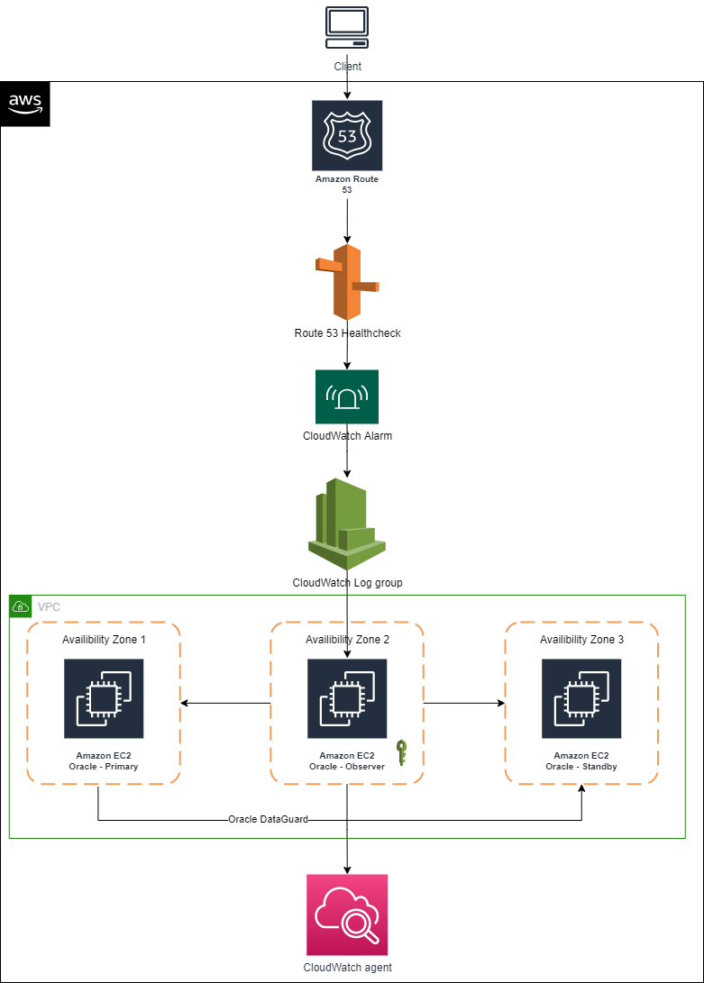
Database failover with Amazon Route 53 and Oracle Data Guard
The following walkthrough defines the steps you can take to make database failover happen without manual intervention using Amazon Route 53 and Oracle Data Guard.
Prerequisites
Before getting started, review the following prerequisites for this solution:
Walkthrough
Step 1. Create Oracle Database Service
For applications to connect without manual intervention on event of failure, we recommend creating an Oracle database service using the Oracle DBMS_Package called DBMS_SERVICE.
exec dbms_service.CREATE_SERVICE(SERVICE_NAME=>'DB_SERVICE_FOR_APP', NETWORK_NAME=>'DB_SERVICE_FOR_APP');
exec dbms_service.START_SERVICE('DB_SERVICE_FOR_APP');
Step 2. Network configuration
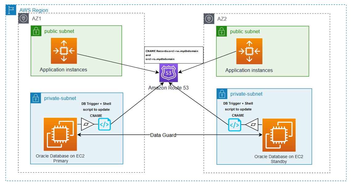
Applications can connect to the database seamlessly without manual intervention in an event of a failover from the Primary database to Standby using the Oracle Transparent Application Failover (TAF) approach, though TAF requires updating application connection strings in case of a host IP change.
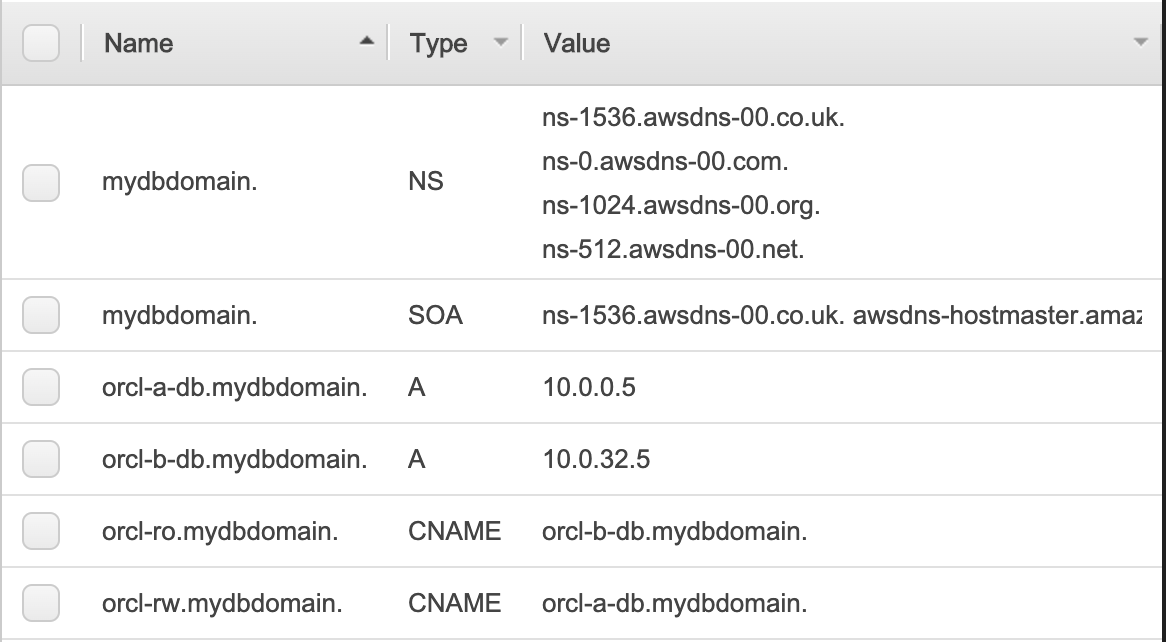
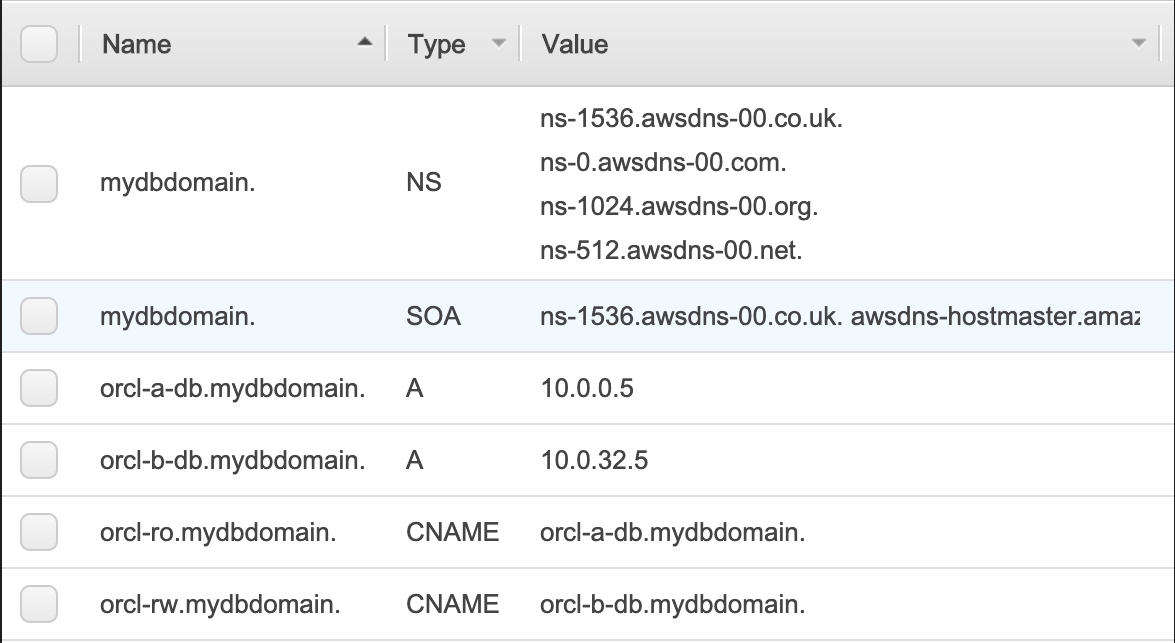
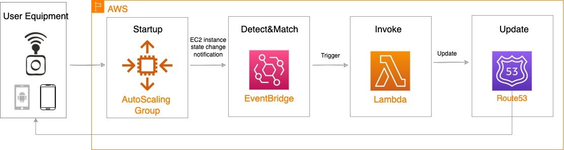
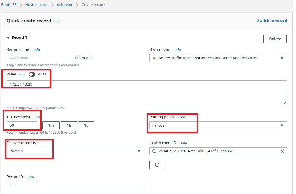
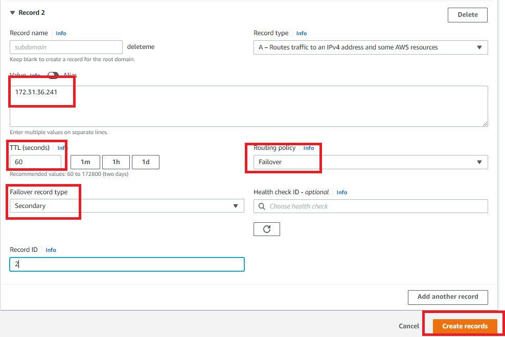
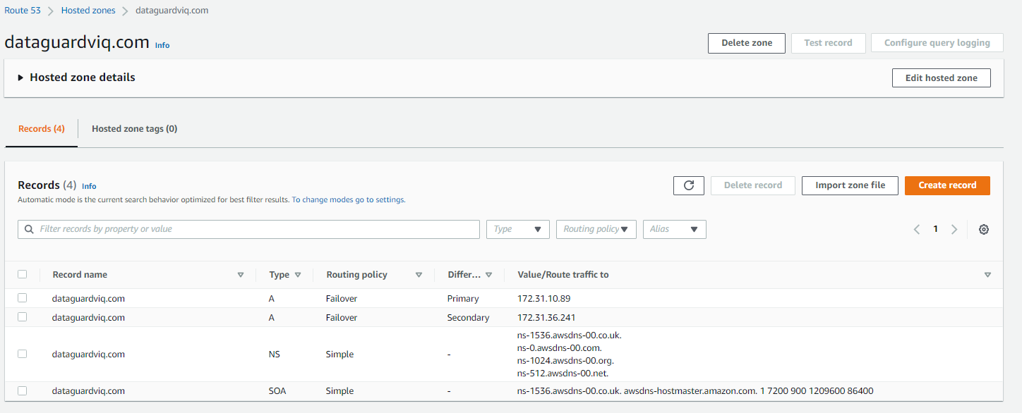
The following approach using Amazon Route 53 is recommended for added flexibility and scalability. Route 53 has DNS A records that map to the database instance IPs and CNAME records that can redirect DNS queries to A records. The following depicts the DNS mapping. The CNAME, along with the database service name, can be used by the application in its network configuration.
Database_Name =
(DESCRIPTION =
(ADDRESS_LIST =
(ADDRESS = (PROTOCOL = TCP)(HOST = <db_cname>)(PORT = 1521))
(connect_data =
(service_name = <db_service_name>)
)) )
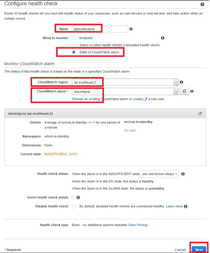
To update the CNAME in Route 53 to map to the Primary host automatically in the event of failure, follow these steps.
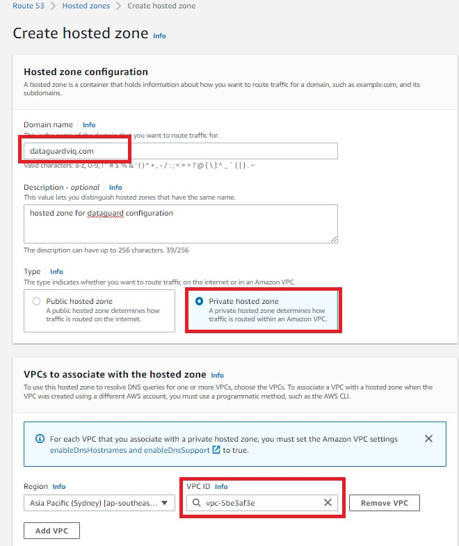
Step 3. Route 53 setup
Create a script named route53update.sh and place it on the database hosts using the following code.
#!/bin/bash
export ORACLE_HOME="<<change>> "
export LD_LIBRARY_PATH=$ORACLE_HOME/lib
export PATH=$ORACLE_HOME/bin:$PATH:/usr/local/bin:/usr/bin
LOG_FILE="/tmp/switch_dns_$$.log"
DNS_DOMAIN="<<change>> "
ACTIVE_DB_CNAME="<<change>> "
HOSTED_ZONE_ID="<<change>> "
TTL="<<change>> "
update_dns () {
TMPFILE="/tmp/route53_dns_$$.log"
cat > ${TMPFILE} << EOF
{
"Comment":"Updating DNS of record ${1}.${DNS_DOMAIN}",
"Changes":[
{
"Action":"UPSERT",
"ResourceRecordSet":{
"ResourceRecords":[
{
"Value":"$2"
}
],
"Name":"${1}.${DNS_DOMAIN}.",
"Type":"CNAME",
"TTL":$TTL
}
}
]
}
EOF
/usr/local/bin/aws route53 change-resource-record-sets \
--hosted-zone-id $HOSTED_ZONE_ID \
--change-batch file://"$TMPFILE" >> "$LOG_FILE"
}
prim_uniq_sid=`$ORACLE_HOME/bin/sqlplus -s / as sysdba <<EOF
set feedback off echo off lines 2000 head off
select upper(db_unique_name) from v\\$dataguard_config where DEST_ROLE='PRIMARY DATABASE';
EOF`
prim_uniq_sid=`echo $prim_uniq_sid| sed 's/^[ \t]*//;s/[ \t]*$//'`
host_current=`$ORACLE_HOME/bin/tnsping ${prim_uniq_sid}|sed -n 's/\(.*Host\)\([^)]*\)\(.*\)/\2/pi' |sed 's/=//g'|sed 's/^[ \t]*//;s/[ \t]*$//'`
dns_current_host=`/usr/local/bin/aws route53 list-resource-record-sets --hosted-zone-id $HOSTED_ZONE_ID --query "ResourceRecordSets[?Name == '${ACTIVE_DB_CNAME}.${DNS_DOMAIN}.'].ResourceRecords" --output text`
if [ "$host_current" != "$dns_current_host" ]; then
update_dns ${ACTIVE_DB_CNAME} $host_current
fi
Step 4. Database job setup
Create a job in the Oracle Primary database to execute the shell script just introduced to initiate in the event of failover using the following code.
begin
dbms_scheduler.create_job
(
job_name => 'route53update',
job_type => 'executable',
number_of_arguments => 0,
job_action => '/<<location of script>>/ route53update.sh',
auto_drop => false
);
dbms_scheduler.enable('route53update');
end;
/
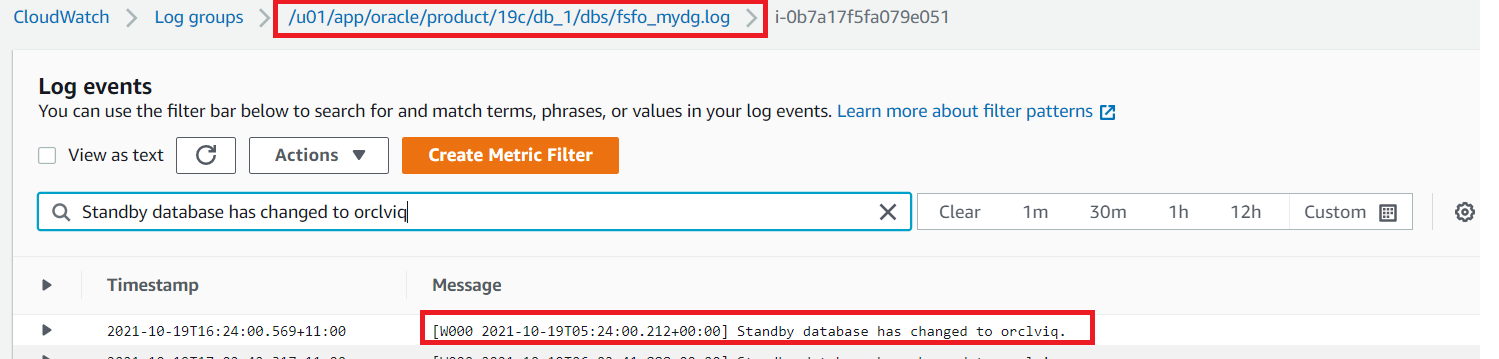
Step 5. Database trigger setup
In an event of a failure, the Primary will failover and the Standby starts up as the new Primary. A trigger needs to be created on the Primary database to execute the job on any failover to update the Route53 CNAME using the following code.
create or replace trigger SYS.Update_Route53_Record
AFTER STARTUP ON DATABASE
DECLARE
db_role varchar2(16);
db_mode varchar2(20);BEGIN
select database_role, open_mode into db_role, db_mode from v$database;
if db_role = 'PRIMARY' then
dbms_scheduler.run_job('route53update') ;
END IF;
END;
/
Alternate Option 1: Single Region with multi-AZ
This option is a minimum recommended configuration to maintain high availability for Oracle databases on Amazon EC2 for customers who do not have a multi-region setup.
- Advantage: Protects against Amazon EC2 service outage in a single AZ.
- Limitation: Does not protect against Amazon EC2 service outages in a single Region.
In this architecture, Oracle Data Guard Fast Sync replication exists between the Oracle database instance in a multi-AZ setup with the Primary database (Read Write) in AZ 1 and the Standby database (Read Only) in AZ 2.
If the primary database is unreachable due to any failure, the observer will failover to the standby database in a different AZ. Applications can continue to connect to the database with zero data loss due to synchronous replication between AZ using the Maximum Availability/Maximum Protection mode setup in Oracle Data Guard. If the primary database is in us-east-1a and standby in us-east-1b, the RedoRoutes property can be defined as follows.
Oracle RedoRoutes setup example:
dgmgrl> edit database DB_1A set property RedoRoutes= '(LOCAL: (DB_1B FASTSYNC)'
dgmgrl> edit database DB_1B set property RedoRoutes= '(LOCAL: (DB_1A FASTSYNC)'
For more information on how disaster recovery works in the AWS Cloud, visit the Disaster recovery is different in the cloud section of the AWS Well-Architected Framework. For more on Oracle RedoRoutes setup, refer to the Oracle Redo Routing Rules documentation.
Alternate Option 2: Multi-AZ with multi-Region with single AZ
This option is recommended to maintain high availability for an Oracle database on Amazon EC2 for customers who need multi-region availability. It provides protection against the rare unavailability of Amazon EC2 instances in the primary Region, in which case a disaster recovery environment is provided.
- Advantage: Protects against Amazon EC2 service outages in a 2 AZ or AWS Region.
- Limitation: Decreased resiliency without high availability on Amazon EC2 service outage in an entire Region
In this architecture, Oracle Data Guard Fast Sync replication exists between the Oracle database instance in multi-AZ within the single Region, with the Primary database in AZ 1 in Region A and Standby database in AZ 2 in Region A. There is an asynchronous replication setup between the Standby database cross-Region.
Asynchronous replication is recommended between Region replication to avoid network latency issue. A cascading standby setup ensures there is no additional performance impact on the primary database to send data to multiple standbys.
If the primary database is unreachable, failover happens between AZs in Region A. In the event of an Amazon EC2 service outage in a Region, failover occurs to Region B, resulting in high availability with minimal data loss based on the data change rate amount. If the primary database is in us-east-1a and standby in us-east-1b (Fast Sync) and us-east-2a (Async), the RedoRoutes property can be defined as follows.
Oracle RedoRoutes setup example:
dgmgrl > edit database DB_1A set property RedoRoutes= '(LOCAL: (DB_1B FASTSYNC PRIORITY=1, DB_2A ASYNC PRIORITY=2))(DB_1B: DB_2A ASYNC)(DB_2A: DB_1B ASYNC)'
dgmgrl > edit database DB_1B set property RedoRoutes= '(LOCAL: (DB_1A FASTSYNC PRIORITY=1, DB_2A ASYNC PRIORITY=2)) (DB_1A: DB_2A ASYNC)'
dgmgrl > edit database DB_1B set property RedoRoutes= '(LOCAL: (DB_1A FASTSYNC PRIORITY=1, DB_1B ASYNC PRIORITY=2))'
Cleaning up
The services involved in this solution incur costs. When you’re done using this solution, clean up the following resources:
- Amazon EC2 instances – Stop or delete (terminate) the Amazon EC2 instances that you provisioned.
- Route53 – Delete the hosted Zone ID and A records/CNAMEs created.
Conclusion
This blog post demonstrates how high availability and disaster recovery can be achieved for an Oracle database on an Amazon EC2 instance using Oracle Data Guard. Using the architectures in this post, you can achieve zero data loss with the Oracle Fast-Start Failover option within the same Region or cross-Region on Amazon EC2.
You can also use this architecture to replicate data from an Oracle database on Amazon EC2 to an Oracle database hosted outside of the AWS cloud. With Oracle Cascading Standby and Oracle RedoRoutes, you can remove high dependency on the Primary database to improve overall performance.