Tag Archives: Best practices

Best practices for managing Terraform State files in AWS CI/CD Pipeline

Post Syndicated from Arun Kumar Selvaraj original https://aws.amazon.com/blogs/devops/best-practices-for-managing-terraform-state-files-in-aws-ci-cd-pipeline/

Introduction

Today customers want to reduce manual operations for deploying and maintaining their infrastructure. The recommended method to deploy and manage infrastructure on AWS is to follow Infrastructure-As-Code (IaC) model using tools like AWS CloudFormation, AWS Cloud Development Kit (AWS CDK) or Terraform.

One of the critical components in terraform is managing the state file which keeps track of your configuration and resources. When you run terraform in an AWS CI/CD pipeline the state file has to be stored in a secured, common path to which the pipeline has access to. You need a mechanism to lock it when multiple developers in the team want to access it at the same time.

In this blog post, we will explain how to manage terraform state files in AWS, best practices on configuring them in AWS and an example of how you can manage it efficiently in your Continuous Integration pipeline in AWS when used with AWS Developer Tools such as AWS CodeCommit and AWS CodeBuild. This blog post assumes you have a basic knowledge of terraform, AWS Developer Tools and AWS CI/CD pipeline. Let’s dive in!

Challenges with handling state files

By default, the state file is stored locally where terraform runs, which is not a problem if you are a single developer working on the deployment. However if not, it is not ideal to store state files locally as you may run into following problems:

  • When working in teams or collaborative environments, multiple people need access to the state file
  • Data in the state file is stored in plain text which may contain secrets or sensitive information
  • Local files can get lost, corrupted, or deleted

Best practices for handling state files

The recommended practice for managing state files is to use terraform’s built-in support for remote backends. These are:

Remote backend on Amazon Simple Storage Service (Amazon S3): You can configure terraform to store state files in an Amazon S3 bucket which provides a durable and scalable storage solution. Storing on Amazon S3 also enables collaboration that allows you to share state file with others.

Remote backend on Amazon S3 with Amazon DynamoDB: In addition to using an Amazon S3 bucket for managing the files, you can use an Amazon DynamoDB table to lock the state file. This will allow only one person to modify a particular state file at any given time. It will help to avoid conflicts and enable safe concurrent access to the state file.

There are other options available as well such as remote backend on terraform cloud and third party backends. Ultimately, the best method for managing terraform state files on AWS will depend on your specific requirements.

When deploying terraform on AWS, the preferred choice of managing state is using Amazon S3 with Amazon DynamoDB.

AWS configurations for managing state files

  1. Create an Amazon S3 bucket using terraform. Implement security measures for Amazon S3 bucket by creating an AWS Identity and Access Management (AWS IAM) policy or Amazon S3 Bucket Policy. Thus you can restrict access, configure object versioning for data protection and recovery, and enable AES256 encryption with SSE-KMS for encryption control.
  1. Next create an Amazon DynamoDB table using terraform with Primary key set to LockID. You can also set any additional configuration options such as read/write capacity units. Once the table is created, you will configure the terraform backend to use it for state locking by specifying the table name in the terraform block of your configuration.
  1. For a single AWS account with multiple environments and projects, you can use a single Amazon S3 bucket. If you have multiple applications in multiple environments across multiple AWS accounts, you can create one Amazon S3 bucket for each account. In that Amazon S3 bucket, you can create appropriate folders for each environment, storing project state files with specific prefixes.

Now that you know how to handle terraform state files on AWS, let’s look at an example of how you can configure them in a Continuous Integration pipeline in AWS.

Architecture

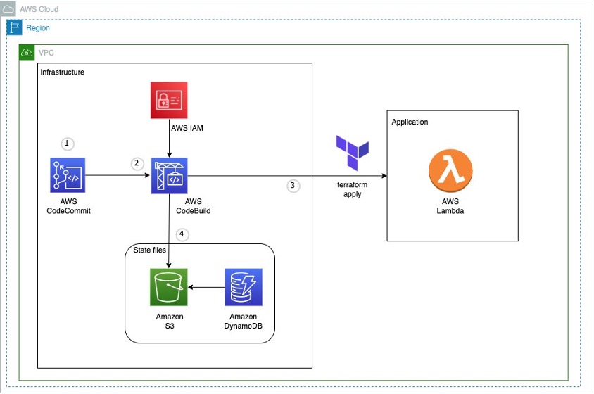
Architecture on how to use terraform in an AWS CI pipeline

Figure 1: Example architecture on how to use terraform in an AWS CI pipeline

This diagram outlines the workflow implemented in this blog:

  1. The AWS CodeCommit repository contains the application code
  2. The AWS CodeBuild job contains the buildspec files and references the source code in AWS CodeCommit
  3. The AWS Lambda function contains the application code created after running terraform apply
  4. Amazon S3 contains the state file created after running terraform apply. Amazon DynamoDB locks the state file present in Amazon S3

Implementation

Pre-requisites

Before you begin, you must complete the following prerequisites:

Setting up the environment

  1. You need an AWS access key ID and secret access key to configure AWS CLI. To learn more about configuring the AWS CLI, follow these instructions.
  2. Clone the repo for complete example: git clone https://github.com/aws-samples/manage-terraform-statefiles-in-aws-pipeline
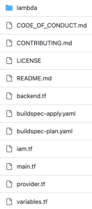
  3. After cloning, you could see the following folder structure:
AWS CodeCommit repository structure

Figure 2: AWS CodeCommit repository structure

Let’s break down the terraform code into 2 parts – one for preparing the infrastructure and another for preparing the application.

Preparing the Infrastructure

  1. The main.tf file is the core component that does below:
      • It creates an Amazon S3 bucket to store the state file. We configure bucket ACL, bucket versioning and encryption so that the state file is secure.
      • It creates an Amazon DynamoDB table which will be used to lock the state file.
      • It creates two AWS CodeBuild projects, one for ‘terraform plan’ and another for ‘terraform apply’.

    Note – It also has the code block (commented out by default) to create AWS Lambda which you will use at a later stage.

  1. AWS CodeBuild projects should be able to access Amazon S3, Amazon DynamoDB, AWS CodeCommit and AWS Lambda. So, the AWS IAM role with appropriate permissions required to access these resources are created via iam.tf file.
  1. Next you will find two buildspec files named buildspec-plan.yaml and buildspec-apply.yaml that will execute terraform commands – terraform plan and terraform apply respectively.
  1. Modify AWS region in the provider.tf file.
  1. Update Amazon S3 bucket name, Amazon DynamoDB table name, AWS CodeBuild compute types, AWS Lambda role and policy names to required values using variable.tf file. You can also use this file to easily customize parameters for different environments.

With this, the infrastructure setup is complete.

You can use your local terminal and execute below commands in the same order to deploy the above-mentioned resources in your AWS account.

terraform init
terraform validate
terraform plan
terraform apply

Once the apply is successful and all the above resources have been successfully deployed in your AWS account, proceed with deploying your application. 

Preparing the Application

  1. In the cloned repository, use the backend.tf file to create your own Amazon S3 backend to store the state file. By default, it will have below values. You can override them with your required values.
bucket = "tfbackend-bucket" 
key    = "terraform.tfstate" 
region = "eu-central-1"
  1. The repository has sample python code stored in main.py that returns a simple message when invoked.
  1. In the main.tf file, you can find the below block of code to create and deploy the Lambda function that uses the main.py code (uncomment these code blocks).
data "archive_file" "lambda_archive_file" {
    ……
}

resource "aws_lambda_function" "lambda" {
    ……
}
  1. Now you can deploy the application using AWS CodeBuild instead of running terraform commands locally which is the whole point and advantage of using AWS CodeBuild.
  1. Run the two AWS CodeBuild projects to execute terraform plan and terraform apply again.
  1. Once successful, you can verify your deployment by testing the code in AWS Lambda. To test a lambda function (console):
    • Open AWS Lambda console and select your function “tf-codebuild”
    • In the navigation pane, in Code section, click Test to create a test event
    • Provide your required name, for example “test-lambda”
    • Accept default values and click Save
    • Click Test again to trigger your test event “test-lambda”

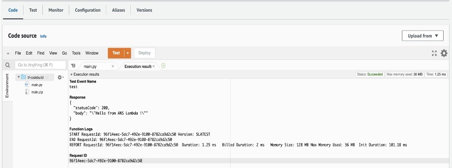
It should return the sample message you provided in your main.py file. In the default case, it will display “Hello from AWS Lambda !” message as shown below.

Sample Amazon Lambda function response

Figure 3: Sample Amazon Lambda function response

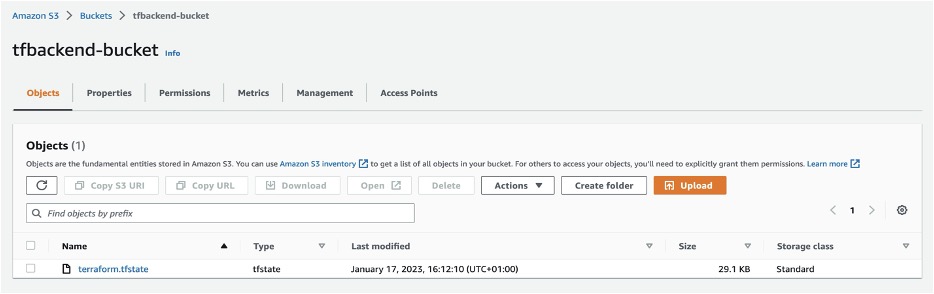
  1. To verify your state file, go to Amazon S3 console and select the backend bucket created (tfbackend-bucket). It will contain your state file.
Amazon S3 bucket with terraform state file

Figure 4: Amazon S3 bucket with terraform state file

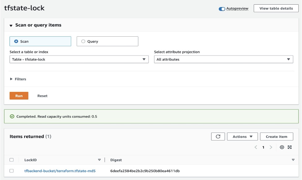
  1. Open Amazon DynamoDB console and check your table tfstate-lock and it will have an entry with LockID.
Amazon DynamoDB table with LockID

Figure 5: Amazon DynamoDB table with LockID

Thus, you have securely stored and locked your terraform state file using terraform backend in a Continuous Integration pipeline.

Cleanup

To delete all the resources created as part of the repository, run the below command from your terminal.

terraform destroy

Conclusion

In this blog post, we explored the fundamentals of terraform state files, discussed best practices for their secure storage within AWS environments and also mechanisms for locking these files to prevent unauthorized team access. And finally, we showed you an example of how efficiently you can manage them in a Continuous Integration pipeline in AWS.

You can apply the same methodology to manage state files in a Continuous Delivery pipeline in AWS. For more information, see CI/CD pipeline on AWS, Terraform backends types, Purpose of terraform state.

Arun Kumar Selvaraj

Arun Kumar Selvaraj is a Cloud Infrastructure Architect with AWS Professional Services. He loves building world class capability that provides thought leadership, operating standards and platform to deliver accelerated migration and development paths for his customers. His interests include Migration, CCoE, IaC, Python, DevOps, Containers and Networking.

Manasi Bhutada

Manasi Bhutada is an ISV Solutions Architect based in the Netherlands. She helps customers design and implement well architected solutions in AWS that address their business problems. She is passionate about data analytics and networking. Beyond work she enjoys experimenting with food, playing pickleball, and diving into fun board games.

Improve your ETL performance using multiple Redshift warehouses for writes

Post Syndicated from Ryan Waldorf original https://aws.amazon.com/blogs/big-data/improve-your-etl-performance-using-multiple-redshift-warehouses-for-writes/

Amazon Redshift is a fast, petabyte-scale, cloud data warehouse that tens of thousands of customers rely on to power their analytics workloads. Thousands of customers use Amazon Redshift read data sharing to enable instant, granular, and fast data access across Redshift provisioned clusters and serverless workgroups. This allows you to scale your read workloads to thousands of concurrent users without having to move or copy the data.

Now, at Amazon Redshift we are announcing multi-data warehouse writes through data sharing in public preview. This allows you to achieve better performance for extract, transform, and load (ETL) workloads by using different warehouses of different types and sizes based on your workload needs. Additionally, this allows you to easily keep your ETL jobs running more predictably as you can split them between warehouses in a few clicks, monitor and control costs as each warehouse has its own monitoring and cost controls, and foster collaboration as you can enable different teams to write to another team’s databases in just a few clicks.

The data is live and available across all warehouses as soon as it is committed, even when it’s written to cross-account or cross-region. For preview you can use a combination of ra3.4xl clusters, ra3.16xl clusters, or serverless workgroups.

In this post, we discuss when you should consider using multiple warehouses to write to the same databases, explain how multi-warehouse writes through data sharing works, and walk you through an example on how to use multiple warehouses to write to the same database.

Reasons for using multiple warehouses to write to the same databases

In this section, we discuss some of the reasons why you should consider using multiple warehouses to write to the same database.

Better performance and predictability for mixed workloads

Customers often start with a warehouse sized to fit their initial workload needs. For example, if you need to support occasional user queries and nightly ingestion of 10 million rows of purchase data, a 32 RPU workgroup may be perfectly suited for your needs. However, adding a new hourly ingestion of 400 million rows of user website and app interactions could slow existing users’ response times as the new workload consumes significant resources. You could resize to a larger workgroup so read and write workloads complete quickly without fighting over resources. However, this may provide unneeded power and cost for existing workloads. Also, because workloads share compute, a spike in one workload can affect the ability of other workloads to meet their SLAs.

The following diagram illustrates a single-warehouse architecture.

Single-Warehouse ETL Architecture. Three separate workloads--a Purchase History ETL job ingesting 10M rows nightly, Users running 25 read queries per hour, and a Web Interactions ETL job ingesting 400M rows/hour--all using the same 256 RPU Amazon Redshift serverless workgroup to read and write from the database called Customer DB.

With the ability to write through datashares, you can now separate the new user website and app interactions ETL into a separate, larger workgroup so that it completes quickly with the performance you need without impacting the cost or completion time of your existing workloads. The following diagram illustrates this multi-warehouse architecture.

Multi-Warehouse ETL Architecture. Two workloads--a Purchase History ETL job ingesting 10M rows nightly and users running 25 read queries per hour--using a 32 RPU serverless workgroup to read from and write to the database Customer DB. It shows a separate workload--a Web Interactions ETL job ingesting 400M rows/hour--using a separate 128 RPU serverless workgroup to write to the database Customer DB.

The multi-warehouse architecture enables you to have all write workloads complete on time with less combined compute, and subsequently lower cost, than a single warehouse supporting all workloads.

Control and monitor costs

When you use a single warehouse for all your ETL jobs, it can be difficult to understand which workloads are contributing to your costs. For instance, you may have one team running an ETL workload ingesting data from a CRM system while another team is ingesting data from internal operational systems. It’s hard for you to monitor and control the costs for the workloads because queries are running together using the same compute in the warehouse. By splitting the write workloads into separate warehouses, you can separately monitor and control costs while ensuring the workloads can progress independently without resource conflict.

Collaborate on live data with ease

The are times when two teams use different warehouses for data governance, compute performance, or cost reasons, but also at times need to write to the same shared data. For instance, you may have a set of customer 360 tables that need to be updated live as customers interact with your marketing, sales, and customer service teams. When these teams use different warehouses, keeping this data live can be difficult because you may have to build a multi-service ETL pipeline using tools like Amazon Simple Storage Service (Amazon S3), Amazon Simple Notification Service (Amazon SNS), Amazon Simple Queue Service (Amazon SQS), and AWS Lambda to track live changes in each team’s data and ingest it into a single source.

With the ability to write through datashares, you can grant granular permissions on your database objects (for example, SELECT on one table, and SELECT, INSERT, and TRUNCATE on another) to different teams using different warehouses in a few clicks. This enables teams to start writing to the shared objects using their own warehouses. The data is live and available to all warehouses as soon as it is committed, and this even works if the warehouses are using different accounts and regions.

In the following sections, we walk you through how to use multiple warehouses to write to the same databases via data sharing.

Solution overview

We use the following terminology in this solution:

  • Namespace – A logical container for database objects, users and roles, their permissions on database objects, and compute (serverless workgroups and provisioned clusters).
  • Datashare – The unit of sharing for data sharing. You grant permissions on objects to datashares.
  • Producer – The warehouse that creates the datashare, grants permissions on objects to datashares, and grants other warehouses and accounts access to the datashare.
  • Consumer – The warehouse that is granted access to the datashare. You can think of consumers as datashare tenants.

This use case involves a customer with two warehouses: a primary warehouse used for attached to the primary namespace for most read and write queries, and a secondary warehouse attached to a secondary namespace that is primarily used to write to the primary namespace. We use the publicly available 10 GB TPCH dataset from AWS Labs, hosted in an S3 bucket. You can copy and paste many of the commands to follow along. Although it’s small for a data warehouse, this dataset allows easy functional testing of this feature.

The following diagram illustrates our solution architecture.

Architecture Diagram showing Two Warehouses for ETL

We set up the primary namespace by connecting to it via its warehouse, creating a marketing database in it with a prod and staging schema, and creating three tables in the prod schema called region, nation, and af_customer. We then load data into the region and nation tables using the warehouse. We do not ingest data into the af_customer table.

We then create a datashare in the primary namespace. We grant the datashare the ability to create objects in the staging schema and the ability to select, insert, update, and delete from objects in the prod schema. We then grant usage on the schema to another namespace in the account.

At that point, we connect to the secondary warehouse. We create a database from a datashare in that warehouse as well as a new user. We then grant permissions on the datashare object to the new user. Then we reconnect to the secondary warehouse as the new user.

We then create a customer table in the datashare’s staging schema and copy data from the TPCH 10 customer dataset into the staging table. We insert staging customer table data into the shared af_customer production table, and then truncate the table.

At this point, the ETL is complete and you are able to read the data in the primary namespace, inserted by the secondary ETL warehouse, from both the primary warehouse and the secondary ETL warehouse.

Prerequisites

To follow along with this post, you should have the following prerequisites:

  • Two warehouses created with the PREVIEW_2023 track. The warehouses can be a mix of serverless workgroups, ra3.4xl clusters, and ra3.16xl clusters.
  • Access to a superuser in both warehouses.
  • An AWS Identity and Access Management (IAM) role that is able to ingest data from Amazon Redshift to Amazon S3 (Amazon Redshift creates one by default when you create a cluster or serverless workgroup).
  • For cross-account only, you need access to an IAM user or role that is allowed to authorize datashares. For the IAM policy, refer to Sharing datashares.

Refer to Sharing both read and write data within an AWS account or across accounts (preview) for the most up-to-date information.

Set up the primary namespace (producer)

In this section, we show how to set up the primary (producer) namespace we will use to store our data.

Connect to producer

Complete the following steps to connect to the producer:

  1. On the Amazon Redshift console, choose Query editor v2 in the navigation pane.

In the query editor v2, you can see all the warehouses you have access to in the left pane. You can expand them to see their databases.

  1. Connect to your primary warehouse using a superuser.
  2. Run the following command to create the marketing database:
CREATE DATABASE marketing;

Create the database objects to share

Complete the following steps to create your database objects to share:

  1. After you create the marketing database, switch your database connection to the marketing database.

You may need to refresh your page to be able to see it.

  1. Run the following commands to create the two schemas you intend to share:
CREATE SCHEMA staging;
CREATE SCHEMA prod;
  1. Create the tables to share with the following code. These are standard DDL statements coming from the AWS Labs DDL file with modified table names.
create table prod.region (
  r_regionkey int4 not null,
  r_name char(25) not null ,
  r_comment varchar(152) not null,
  Primary Key(R_REGIONKEY)
);

create table prod.nation (
  n_nationkey int4 not null,
  n_name char(25) not null ,
  n_regionkey int4 not null,
  n_comment varchar(152) not null,
  Primary Key(N_NATIONKEY)
);

create table prod.af_customer (
  c_custkey int8 not null ,
  c_name varchar(25) not null,
  c_address varchar(40) not null,
  c_nationkey int4 not null,
  c_phone char(15) not null,
  c_acctbal numeric(12,2) not null,
  c_mktsegment char(10) not null,
  c_comment varchar(117) not null,
  Primary Key(C_CUSTKEY)
) distkey(c_custkey) sortkey(c_custkey);

Copy data into the region and nation tables

Run the following commands to copy data from the AWS Labs S3 bucket into the region and nation tables. If you created a cluster while keeping the default created IAM role, you can copy and paste the following commands to load data into your tables:

copy prod.nation from 's3://redshift-downloads/TPC-H/2.18/10GB/nation.tbl' iam_role default delimiter '|' region 'us-east-1';
copy prod.region from 's3://redshift-downloads/TPC-H/2.18/10GB/region.tbl' iam_role default delimiter '|' region 'us-east-1';

Create the datashare

Create the datashare using the following command:

create datashare marketing publicaccessible true;

The publicaccessible setting specifies whether or not a datashare can be used by consumers with publicly accessible provisioned clusters and serverless workgroups. If your warehouses are not publicly accessible, you can ignore that field.

Grant permissions on schemas to the datashare

To add objects with permissions to the datashare, use the grant syntax, specifying the datashare you’d like to grant the permissions to:

grant usage on schema prod to datashare marketing;
grant usage, create on schema staging to datashare marketing;

This allows the datashare consumers to use objects added to the prod schema and use and create objects added to the staging schema. To maintain backward compatibility, if you use the alter datashare command to add a schema, it will be the equivalent of granting usage on the schema.

Grant permissions on tables to the datashare

Now you can grant access to tables to the datashare using the grant syntax, specifying the permissions and the datashare. The following code grants all privileges on the af_customer table to the datashare:

grant all on table prod.af_customer to datashare marketing;

To maintain backward compatibility, if you use the alter datashare command to add a table, it will be the equivalent of granting select on the table.

Additionally, we’ve added scoped permissions that allow you to grant the same permission to all current and future objects within the datashare. We add the scoped select permission on the prod schema tables to the datashare:

grant select for tables in schema prod to datashare marketing;

After this grant, the customer will have select permissions on all current and future tables in the prod schema. This gives them select access on the region and nation tables.

View permissions granted to the datashare

You can view permissions granted to the datashare by running the following command:

show access for datashare marketing;

Grant permissions to the secondary ETL namespace

You can grant permissions to the secondary ETL namespace using the existing syntax. You do this by specifying the namespace ID. You can find the namespace on the namespace details page if your secondary ETL namespace is serverless, as part of the namespace ID in the cluster details page if your secondary ETL namespace is provisioned, or by connecting to the secondary ETL warehouse in the query editor v2 and running select current_namespace. You can then grant access to the other namespace with the following command (change the consumer namespace to the namespace UID of your own secondary ETL warehouse):

grant usage on datashare marketing to namespace '<consumer_namespace>';

Set up the secondary ETL namespace (consumer)

At this point, you’re ready to set up your secondary (consumer) ETL warehouse to start writing to the shared data.

Create a database from the datashare

Complete the following steps to create your database:

  1. In the query editor v2, switch to the secondary ETL warehouse.
  2. Run the command show datashares to see the marketing datashare as well as the datashare producer’s namespace.
  3. Use that namespace to create a database from the datashare, as shown in the following code:
create database marketing_ds_db with permissions from datashare marketing of namespace '&lt;producer_namespace&gt;';

Specifying with permissions allows you to grant granular permissions to individual database users and roles. Without this, if you grant usage permissions on the datashare database, users and roles get all permissions on all objects within the datashare database.

Create a user and grant permissions to that user

Create a user using the CREATE USER command:

create user data_engineer password '[choose a secure password]';
grant usage on database marketing_ds_db to data_engineer;
grant all on schema marketing_ds_db.prod to data_engineer;
grant all on schema marketing_ds_db.staging to data_engineer;
grant all on all tables in schema marketing_ds_db.staging to data_engineer;
grant all on all tables in schema marketing_ds_db.prod to data_engineer;

With these grants, you’ve given the user data_engineer all permissions on all objects in the datashare. Additionally, you’ve granted all permissions available in the schemas as scoped permissions for data_engineer. Any permissions on any objects added to those schemas will be automatically granted to data_engineer.

At this point, you can continue the steps using either the admin user you’re currently signed in as or the data_engineer.

Options for writing to the datashare database

You can write data to the datashare database three ways.

Use three-part notation while connected to a local database

Like with read data sharing, you can use three-part notation to reference the datashare database objects. For instance, insert into marketing_ds_db.prod.customer. Note that you can’t use multi-statement transactions to write to objects in the datashare database like this.

Connect directly to the datashare database

You can connect directly to the datashare database via the Redshift JDBC, ODBC, or Python driver, in addition to the Amazon Redshift Data API (new). To connect like this, specify the datashare database name in the connection string. This allows you to write to the datashare database using two-part notation and use multi-statement transactions to write to the datashare database. Note that some system and catalog tables are not available this way.

Run the use command

You can now specify that you want to use another database with the command use <database_name>. This allows you to write to the datashare database using two-part notation and use multi-statement transactions to write to the datashare database. Note that some system and catalog tables are not available this way. Also, when querying system and catalog tables, you will be querying the system and catalog tables of the database you are connected to, not the database you are using.

To try this method, run the following command:

use marketing_ds_db;

Start writing to the datashare database

In this section, we show how to write to the datashare database using the second and third options we discussed (direct connection or use command). We use the AWS Labs provided SQL to write to the datashare database.

Create a staging table

Create a table within the staging schema, because you’ve been granted create privileges. We create a table within the datashare’s staging schema with the following DDL statement:

create table staging.customer (
  c_custkey int8 not null ,
  c_name varchar(25) not null,
  c_address varchar(40) not null,
  c_nationkey int4 not null,
  c_phone char(15) not null,
  c_acctbal numeric(12,2) not null,
  c_mktsegment char(10) not null,
  c_comment varchar(117) not null,
  Primary Key(C_CUSTKEY)
) distkey(c_nationkey) sortkey(c_nationkey);

You can use two-part notation because you used the USE command or directly connected to the datashare database. If not, you need to specify the datashare database names as well.

Copy data into the staging table

Copy the customer TPCH 10 data from the AWS Labs public S3 bucket into the table using the following command:

copy staging.customer from 's3://redshift-downloads/TPC-H/2.18/10GB/customer.tbl' iam_role default delimiter '|' region 'us-east-1';

As before, this requires you to have set up the default IAM role when creating this warehouse.

Ingest African customer data to the table prod.af_customer

Run the following command to ingest only the African customer data to the table prod.af_customer:

insert into prod.af_customer
select c.* from staging.customer c
  join prod.nation n on c.c_nationkey = n.n_nationkey
  join prod.region r on n.n_regionkey = r.r_regionkey
  where r.r_regionkey = 0; --0 is the region key for Africa

This requires you to join on the nation and region tables you have select permission for.

Truncate the staging table

You can truncate the staging table so that you can write to it without recreating it in a future job. The truncate action will run transactionally and can be rolled back if you are connected directly to the datashare database or you are using the use command (even if you’re not using a datashare database). Use the following code:

truncate staging.customer;

At this point, you’ve completed ingesting the data to the primary namespace. You can query the af_customer table from both the primary warehouse and secondary ETL warehouse and see the same data.

Conclusion

In this post, we showed how to use multiple warehouses to write to the same database. This solution has the following benefits:

  • You can use provisioned clusters and serverless workgroups of different sizes to write to the same databases
  • You can write across accounts and regions
  • Data is live and available to all warehouses as soon as it is committed
  • Writes work even if the producer warehouse (the warehouse that owns the database) is paused

To learn more about this feature, see Sharing both read and write data within an AWS account or across accounts (preview). Additionally, if you have any feedback, please email us at [email protected].


About the authors

Ryan Waldorf is a Senior Product Manager at Amazon Redshift. Ryan focuses on features that enable customers to define and scale compute including data sharing and concurrency scaling.

Harshida Patel is a Analytics Specialist Principal Solutions Architect, with Amazon Web Services (AWS).

Sudipto Das is a Senior Principal Engineer at Amazon Web Services (AWS). He leads the technical architecture and strategy of multiple database and analytics services in AWS with special focus on Amazon Redshift and Amazon Aurora.

Secure connectivity patterns for Amazon MSK Serverless cross-account access

Post Syndicated from Tamer Soliman original https://aws.amazon.com/blogs/big-data/secure-connectivity-patterns-for-amazon-msk-serverless-cross-account-access/

Amazon MSK Serverless is a cluster type of Amazon Managed Streaming for Apache Kafka (Amazon MSK) that makes it straightforward for you to run Apache Kafka without having to manage and scale cluster capacity. MSK Serverless automatically provisions and scales compute and storage resources. With MSK Serverless, you can use Apache Kafka on demand and pay for the data you stream and retain on a usage basis.

Deploying infrastructure across multiple VPCs and multiple accounts is considered best practice, facilitating scalability while maintaining isolation boundaries. In a multi-account environment, Kafka producers and consumers can exist within the same VPC—however, they are often located in different VPCs, sometimes within the same account, in a different account, or even in multiple different accounts. There is a need for a solution that can extend access to MSK Serverless clusters to producers and consumers from multiple VPCs within the same AWS account and across multiple AWS accounts. The solution needs to be scalable and straightforward to maintain.

In this post, we walk you through multiple solution approaches that address the MSK Serverless cross-VPC and cross-account access connectivity options, and we discuss the advantages and limitations of each approach.

MSK Serverless connectivity and authentication

When an MSK Serverless cluster is created, AWS manages the cluster infrastructure on your behalf and extends private connectivity back to your VPCs through VPC endpoints powered by AWS PrivateLink. You bootstrap your connection to the cluster through a bootstrap server that holds a record of all your underlying brokers.

At creation, a fully qualified domain name (FQDN) is assigned to your cluster bootstrap server. The bootstrap server FQDN has the general format of boot-ClusterUniqueID.xx.kafka-serverless.Region.amazonaws.com, and your cluster brokers follow the format of bxxxx-ClusterUniqueID.xx.kafka-serverless.Region.amazonaws.com, where ClusterUniqueID.xx is unique to your cluster and bxxxx is a dynamic broker range (b0001, b0037, and b0523 can be some of your assigned brokers at a point of time). It’s worth noting that the brokers assigned to your cluster are dynamic and change over time, but your bootstrap address remains the same for the cluster. All your communication with the cluster starts with the bootstrap server that can respond with the list of active brokers when required. For proper Kafka communication, your MSK client needs to be able to resolve the domain names of your bootstrap server as well as all your brokers.

At cluster creation, you specify the VPCs that you would like the cluster to communicate with (up to five VPCs in the same account as your cluster). For each VPC specified during cluster creation, cluster VPC endpoints are created along with a private hosted zone that includes a list of your bootstrap server and all dynamic brokers kept up to date. The private hosted zones facilitate resolving the FQDNs of your bootstrap server and brokers, from within the associated VPCs defined during cluster creation, to the respective VPC endpoints for each.

Cross-account access

To be able to extend private connectivity of your Kafka producers and consumers to your MSK Serverless cluster, you need to consider three main aspects: private connectivity, authentication and authorization, and DNS resolution.

The following diagram highlights the possible connectivity options. Although the diagram shows them all here for demonstration purposes, in most cases, you would use one or more of these options depending on your architecture, not necessary all in the same setup.

MSK cross account connectivity options

In this section, we discuss the different connectivity options along with their pros and cons. We also cover the authentication and DNS resolution aspects associated with the relevant connectivity options.

Private connectivity layer

This is the underlying private network connectivity. You can achieve this connectivity using VPC peering, AWS Transit Gateway, or PrivateLink, as indicated in the preceding diagram. VPC peering simplifies the setup, but it lacks the support for transitive routing. In most cases, peering is used when you have a limited number of VPCs or if your VPCs generally communicate with some limited number of core services VPCs without the need of lateral connectivity or transitive routing. On the other hand, AWS Transit Gateway facilitates transitive routing and can simplify the architecture when you have a large number of VPCs, and especially when lateral connectivity is required. PrivateLink is more suited for extending connectivity to a specific resource unidirectionally across VPCs or accounts without exposing full VPC-to-VPC connectivity, thereby adding a layer of isolation. PrivateLink is useful if you have overlapping CIDRs, which is a case that is not supported by Transit Gateway or VPC peering. PrivateLink is also useful when your connected parties are administrated separately, and when one-way connectivity and isolation are required.

If you choose PrivateLink as a connectivity option, you need to use a Network Load Balancer (NLB) with an IP type target group with its registered targets set as the IP addresses of the zonal endpoints of your MSK Serverless cluster.

Cluster authentication and authorization

In addition to having private connectivity and being able to resolve the bootstrap server and brokers domain names, for your producers and consumers to have access to your cluster, you need to configure your clients with proper credentials. MSK Serverless supports AWS Identity and Access Management (IAM) authentication and authorization. For cross-account access, your MSK client needs to assume a role that has proper credentials to access the cluster. This post focuses mainly on the cross-account connectivity and name resolution aspects. For more details on cross-account authentication and authorization, refer to the following GitHub repo.

DNS resolution

For Kafka producers and consumers located in accounts across the organization to be able to produce and consume to and from the centralized MSK Serverless cluster, they need to be able to resolve the FQDNs of the cluster bootstrap server as well as each of the cluster brokers. Understanding the dynamic nature of broker allocation, the solution will have to accommodate such a requirement. In the next section, we address how we can satisfy this part of the requirements.

Cluster cross-account DNS resolution

Now that we have discussed how MSK Serverless works, how private connectivity is extended, and the authentication and authorization requirements, let’s discuss how DNS resolution works for your cluster.

For every VPC associated with your cluster during cluster creation, a VPC endpoint is created along with a private hosted zone. Private hosted zones enable name resolve of the FQDNs of the cluster bootstrap server and the dynamically allocated brokers, from within each respective VPC. This works well when requests come from within any of the VPCs that were added during cluster creation because they already have the required VPC endpoints and relevant private hosted zones.

Let’s discuss how you can extend name resolution to other VPCs within the same account that were not included during cluster creation, and to others that may be located in other accounts.

You’ve already made your choice of the private connectivity option that best fits your architecture requirements, be it VPC peering, PrivateLink, or Transit Gateway. Assuming that you have also configured your MSK clients to assume roles that have the right IAM credentials in order to facilitate cluster access, you now need to address the name resolution aspect of connectivity. It’s worth noting that, although we list different connectivity options using VPC peering, Transit Gateway, and PrivateLink, in most cases only one or two of these connectivity options are present. You don’t necessarily need to have them all; they are listed here to demonstrate your options, and you are free to choose the ones that best fit your architecture and requirements.

In the following sections, we describe two different methods to address DNS resolution. For each method, there are advantages and limitations.

Private hosted zones

The following diagram highlights the solution architecture and its components. Note that, to simplify the diagram, and to make room for more relevant details required in this section, we have eliminated some of the connectivity options.

Cross-account access using Private Hosted Zones

The solution starts with creating a private hosted zone, followed by creating a VPC association.

Create a private hosted zone

We start by creating a private hosted zone for name resolution. To make the solution scalable and straightforward to maintain, you can choose to create this private hosted zone in the same MSK Serverless cluster account; in some cases, creating the private hosted zone in a centralized networking account is preferred. Having the private hosted zone created in the MSK Serverless cluster account facilitates centralized management of the private hosted zone alongside the MSK cluster. We can then associate the centralized private hosted zone with VPCs within the same account, or in different other accounts. Choosing to centralize your private hosted zones in a networking account can also be a viable solution to consider.

The purpose of the private hosted zone is to be able to resolve the FQDNs of the bootstrap server as well as all the dynamically assigned cluster-associated brokers. As discussed earlier, the bootstrap server FQDN format is boot-ClusterUniqueID.xx.kafka-serverless.Region.amazonaws.com, and the cluster brokers use the format bxxxx-ClusterUniqueID.xx.kafka-serverless.Region.amazonaws.com, with bxxxx being the broker ID. You need to create the new private hosted zone with the primary domain set as kafka-serverless.Region.amazonaws.com, with an A-Alias record called *.kafka-serverless.Region.amazonaws.com pointing to the Regional VPC endpoint of the MSK Serverless cluster in the MSK cluster VPC. This should be sufficient to direct all traffic targeting your cluster to the primary cluster VPC endpoints that you specified in your private hosted zone.

Now that you have created the private hosted zone, for name resolution to work, you need to associate the private hosted zone with every VPC where you have clients for the MSK cluster (producer or consumer).

Associate a private hosted zone with VPCs in the same account

For VPCs that are in the same account as the MSK cluster and weren’t included in the configuration during cluster creation, you can associate them to the private hosted zone created using the AWS Management Console by editing the private hosted zone settings and adding the respective VPCs. For more information, refer to Associating more VPCs with a private hosted zone.

Associate a private hosted zone in cross-account VPCs

For VPCs that are in a different account other than the MSK cluster account, refer to Associating an Amazon VPC and a private hosted zone that you created with different AWS accounts. The key steps are as follows:

  1. Create a VPC association authorization in the account where the private hosted zone is created (in this case, it’s the same account as the MSK Serverless cluster account) to authorize the remote VPCs to be associated with the hosted zone:
aws route53 create-vpc-association-authorization --hosted-zone-id HostedZoneID --vpc VPCRegion=Region,VPCId=vpc-ID
  1. Associate the VPC with the private hosted zone in the account where you have the VPCs with the MSK clients (remote account), referencing the association authorization you created earlier:
aws route53 list-vpc-association-authorizations --hosted-zone-id HostedZoneID
aws route53 associate-vpc-with-hosted-zone --hosted-zone-id HostedZoneID --VPC VPCRegion=Region,VPCId=vpc-ID
  1. Delete the VPC authorization to associate the VPC with the hosted zone:
aws route53 delete-vpc-association-authorization --hosted-zone-id HostedZoneID --vpc VPCRegion=Region,VPCId=vpc-ID

Deleting the authorization doesn’t affect the association, it just prevents you from re-associating the VPC with the hosted zone in the future. If you want to re-associate the VPC with the hosted zone, you’ll need to repeat steps 1 and 2 of this procedure.

Note that your VPC needs to have the enableDnsSupport and enableDnsHostnames DNS attributes enabled for this to work. These two settings can be configured under the VPC DNS settings. For more information, refer to DNS attributes in your VPC.

These procedures work well for all remote accounts when connectivity is extended using VPC peering or Transit Gateway. If your connectivity option uses PrivateLink, the private hosted zone needs to be created in the remote account instead (the account where the PrivateLink VPC endpoints are). In addition, an A-Alias record that resolves to the PrivateLink endpoint instead of the MSK cluster endpoint needs to be created as indicated in the earlier diagram. This will facilitate name resolution to the PrivateLink endpoint. If other VPCs need access to the cluster through that same PrivateLink setup, you need to follow the same private hosted zone association procedure as described earlier and associate your other VPCs with the private hosted zone created for your PrivateLink VPC.

Limitations

The private hosted zones solution has some key limitations.

Firstly, because you’re using kafka-serverless.Region.amazonaws.com as the primary domain for our private hosted zone, and your A-Alias record uses *.kafka-serverless.Region.amazonaws.com, all traffic to the MSK Serverless service originating from any VPC associated with this private hosted zone will be directed to the one specific cluster VPC Regional endpoint that you specified in the hosted zone A-Alias record.

This solution is valid if you have one MSK Serverless cluster in your centralized service VPC. If you need to provide access to multiple MSK Serverless clusters, you can use the same solution but adapt a distributed private hosted zone approach as opposed to a centralized approach. In a distributed private hosted zone approach, each private hosted zone can point to a specific cluster. The VPCs associated with that specific private hosted zone will communicate only to the respective cluster listed under the specific private hosted zone.

In addition, after you establish a VPC association with a private hosted zone resolving *.kafka-serverless.Region.amazonaws.com, the respective VPC will only be able to communicate with the cluster defined in that specific private hosted zone and no other cluster. An exception to this rule is if a local cluster is created within the same client VPC, in which case the clients within the VPC will only be able to communicate with only the local cluster.

You can also use PrivateLink to accommodate multiple clusters by creating a PrivateLink plus private hosted zone per cluster, replicating the configuration steps described earlier.

Both solutions, using distributed private hosted zones or PrivateLink, are still subject to the limitation that for each client VPC, you can only communicate with the one MSK Serverless cluster that your associated private hosted zone is configured for.

In the next section, we discuss another possible solution.

Resolver rules and AWS Resource Access Manager

The following diagram shows a high-level overview of the solution using Amazon Route 53 resolver rules and AWS Resource Access Manager.

Cross-account access using Resolver Rules and Resolver Endpoints

The solution starts with creating Route 53 inbound and outbound resolver endpoints, which are associated with the MSK cluster VPC. Then you create a resolver forwarding rule in the MSK account that is not associated with any VPC. Next, you share the resolver rule across accounts using Resource Access Manager. At the remote account where you need to extend name resolution to, you need to accept the resource share and associate the resolver rules with your target VPCs located in the remote account (the account where the MSK clients are located).

For more information about this approach, refer to the third use case in Simplify DNS management in a multi-account environment with Route 53 Resolver.

This solution accommodates multiple centralized MSK serverless clusters in a more scalable and flexible approach. Therefore, the solution counts on directing DNS requests to be resolved by the VPC where the MSK clusters are. Multiple MSK Serverless clusters can coexist, where clients in a particular VPC can communicate with one or more of them at the same time. This option is not supported with the private hosted zone solution approach.

Limitations

Although this solution has its advantages, it also has a few limitations.

Firstly, for a particular target consumer or producer account, all your MSK Serverless clusters need to be in the same core service VPC in the MSK account. This is due to the fact that the resolver rule is set on an account level and uses.kafka-serverless.Region.amazonaws.com as the primary domain, directing its resolution to one specific VPC resolver endpoint inbound/outbound pair within that service VPC. If you need to have separate clusters in different VPCs, consider creating separate accounts.

The second limitation is that all your client VPCs need to be in the same Region as your core MSK Serverless VPC. The reason behind this limitation is that resolver rules pointing to a resolver endpoint pair (in reality, they point to the outbound endpoint that loops into the inbound endpoints) need to be in the same Region as the resolver rules, and Resource Access Manager will extend the share only within the same Region. However, this solution is good when you have multiple MSK clusters in the same core VPC, and although your remote clients are in different VPCs and accounts, they are still within the same Region. A workaround for this limitation is to duplicate the creation of resolver rules and outbound resolver endpoint in a second Region, where the outbound endpoint loops back through the original first Region inbound resolver endpoint associated with the MSK Serverless cluster VPC (assuming IP connectivity is facilitated). This second Region resolver rule can then be shared using Resource Access Manager within the second Region.

Conclusion

You can configure MSK Serverless cross-VPC and cross-account access in multi-account environments using private hosted zones or Route 53 resolver rules. The solution discussed in this post allows you to centralize your configuration while extending cross-account access, making it a scalable and straightforward-to-maintain solution. You can create your MSK Serverless clusters with cross-account access for producers and consumers, keep your focus on your business outcomes, and gain insights from sources of data across your organization without having to right-size and manage a Kafka infrastructure.


About the Author

Tamer Soliman is a Senior Solutions Architect at AWS. He helps Independent Software Vendor (ISV) customers innovate, build, and scale on AWS. He has over two decades of industry experience, and is an inventor with three granted patents. His experience spans multiple technology domains including telecom, networking, application integration, data analytics, AI/ML, and cloud deployments. He specializes in AWS Networking and has a profound passion for machine leaning, AI, and Generative AI.

SaaS access control using Amazon Verified Permissions with a per-tenant policy store

Post Syndicated from Manuel Heinkel original https://aws.amazon.com/blogs/security/saas-access-control-using-amazon-verified-permissions-with-a-per-tenant-policy-store/

Access control is essential for multi-tenant software as a service (SaaS) applications. SaaS developers must manage permissions, fine-grained authorization, and isolation.

In this post, we demonstrate how you can use Amazon Verified Permissions for access control in a multi-tenant document management SaaS application using a per-tenant policy store approach. We also describe how to enforce the tenant boundary.

We usually see the following access control needs in multi-tenant SaaS applications:

  • Application developers need to define policies that apply across all tenants.
  • Tenant users need to control who can access their resources.
  • Tenant admins need to manage all resources for a tenant.

Additionally, independent software vendors (ISVs) implement tenant isolation to prevent one tenant from accessing the resources of another tenant. Enforcing tenant boundaries is imperative for SaaS businesses and is one of the foundational topics for SaaS providers.

Verified Permissions is a scalable, fine-grained permissions management and authorization service that helps you build and modernize applications without having to implement authorization logic within the code of your application.

Verified Permissions uses the Cedar language to define policies. A Cedar policy is a statement that declares which principals are explicitly permitted, or explicitly forbidden, to perform an action on a resource. The collection of policies defines the authorization rules for your application. Verified Permissions stores the policies in a policy store. A policy store is a container for policies and templates. You can learn more about Cedar policies from the Using Open Source Cedar to Write and Enforce Custom Authorization Policies blog post.

Before Verified Permissions, you had to implement authorization logic within the code of your application. Now, we’ll show you how Verified Permissions helps remove this undifferentiated heavy lifting in an example application.

Multi-tenant document management SaaS application

The application allows to add, share, access and manage documents. It requires the following access controls:

  • Application developers who can define policies that apply across all tenants.
  • Tenant users who can control who can access their documents.
  • Tenant admins who can manage all documents for a tenant.

Let’s start by describing the application architecture and then dive deeper into the design details.

Application architecture overview

There are two approaches to multi-tenant design in Verified Permissions: a single shared policy store and a per-tenant policy store. You can learn about the considerations, trade-offs and guidance for these approaches in the Verified Permissions user guide.

For the example document management SaaS application, we decided to use the per-tenant policy store approach for the following reasons:

  • Low-effort tenant policies isolation
  • The ability to customize templates and schema per tenant
  • Low-effort tenant off-boarding
  • Per-tenant policy store resource quotas

We decided to accept the following trade-offs:

  • High effort to implement global policies management (because the application use case doesn’t require frequent changes to these policies)
  • Medium effort to implement the authorization flow (because we decided that in this context, the above reasons outweigh implementing a mapping from tenant ID to policy store ID)

Figure 1 shows the document management SaaS application architecture. For simplicity, we omitted the frontend and focused on the backend.

Figure 1: Document management SaaS application architecture

Figure 1: Document management SaaS application architecture

  1. A tenant user signs in to an identity provider such as Amazon Cognito. They get a JSON Web Token (JWT), which they use for API requests. The JWT contains claims such as the user_id, which identifies the tenant user, and the tenant_id, which defines which tenant the user belongs to.
  2. The tenant user makes API requests with the JWT to the application.
  3. Amazon API Gateway verifies the validity of the JWT with the identity provider.
  4. If the JWT is valid, API Gateway forwards the request to the compute provider, in this case an AWS Lambda function, for it to run the business logic.
  5. The Lambda function assumes an AWS Identity and Access Management (IAM) role with an IAM policy that allows access to the Amazon DynamoDB table that provides tenant-to-policy-store mapping. The IAM policy scopes down access such that the Lambda function can only access data for the current tenant_id.
  6. The Lambda function looks up the Verified Permissions policy_store_id for the current request. To do this, it extracts the tenant_id from the JWT. The function then retrieves the policy_store_id from the tenant-to-policy-store mapping table.
  7. The Lambda function assumes another IAM role with an IAM policy that allows access to the Verified Permissions policy store, the document metadata table, and the document store. The IAM policy uses tenant_id and policy_store_id to scope down access.
  8. The Lambda function gets or stores documents metadata in a DynamoDB table. The function uses the metadata for Verified Permissions authorization requests.
  9. Using the information from steps 5 and 6, the Lambda function calls Verified Permissions to make an authorization decision or create Cedar policies.
  10. If authorized, the application can then access or store a document.

Application architecture deep dive

Now that you know the architecture for the use cases, let’s review them in more detail and work backwards from the user experience to the related part of the application architecture. The architecture focuses on permissions management. Accessing and storing the actual document is out of scope.

Define policies that apply across all tenants

The application developer must define global policies that include a basic set of access permissions for all tenants. We use Cedar policies to implement these permissions.

Because we’re using a per-tenant policy store approach, the tenant onboarding process should create these policies for each new tenant. Currently, to update policies, the deployment pipeline should apply changes to all policy stores.

The “Add a document” and “Manage all the documents for a tenant” sections that follow include examples of global policies.

Make sure that a tenant can’t edit the policies of another tenant

The application uses IAM to isolate the resources of one tenant from another. Because we’re using a per-tenant policy store approach we can use IAM to isolate one tenant policy store from another.

Architecture

Figure 2: Tenant isolation

Figure 2: Tenant isolation

  1. A tenant user calls an API endpoint using a valid JWT.
  2. The Lambda function uses AWS Security Token Service (AWS STS) to assume an IAM role with an IAM policy that allows access to the tenant-to-policy-store mapping DynamoDB table. The IAM policy only allows access to the table and the entries that belong to the requesting tenant. When the function assumes the role, it uses tenant_id to scope access to the items whose partition key matches the tenant_id. See the How to implement SaaS tenant isolation with ABAC and AWS IAM blog post for examples of such policies.
  3. The Lambda function uses the user’s tenant_id to get the Verified Permissions policy_store_id.
  4. The Lambda function uses the same mechanism as in step 2 to assume a different IAM role using tenant_id and policy_store_id which only allows access to the tenant policy store.
  5. The Lambda function accesses the tenant policy store.

Add a document

When a user first accesses the application, they don’t own any documents. To add a document, the frontend calls the POST /documents endpoint and supplies a document_name in the request’s body.

Cedar policy

We need a global policy that allows every tenant user to add a new document. The tenant onboarding process creates this policy in the tenant’s policy store.

permit (    
  principal,
  action == DocumentsAPI::Action::"addDocument",
  resource
);

This policy allows any principal to add a document. Because we’re using a per-tenant policy store approach, there’s no need to scope the principal to a tenant.

Architecture

Figure 3: Adding a document

Figure 3: Adding a document

  1. A tenant user calls the POST /documents endpoint to add a document.
  2. The Lambda function uses the user’s tenant_id to get the Verified Permissions policy_store_id.
  3. The Lambda function calls the Verified Permissions policy store to check if the tenant user is authorized to add a document.
  4. After successful authorization, the Lambda function adds a new document to the documents metadata database and uploads the document to the documents storage.

The database structure is described in the following table:

tenant_id (Partition key): String document_id (Sort key): String document_name: String document_owner: String
<TENANT_ID> <DOCUMENT_ID> <DOCUMENT_NAME> <USER_ID>
  • tenant_id: The tenant_id from the JWT claims.
  • document_id: A random identifier for the document, created by the application.
  • document_name: The name of the document supplied with the API request.
  • document_owner: The user who created the document. The value is the user_id from the JWT claims.

Share a document with another user of a tenant

After a tenant user has created one or more documents, they might want to share them with other users of the same tenant. To share a document, the frontend calls the POST /shares endpoint and provides the document_id of the document the user wants to share and the user_id of the receiving user.

Cedar policy

We need a global document owner policy that allows the document owner to manage the document, including sharing. The tenant onboarding process creates this policy in the tenant’s policy store.

permit (    
  principal,
  action,
  resource
) when {
  resource.owner == principal && 
  resource.type == "document"
};

The policy allows principals to perform actions on available resources (the document) when the principal is the document owner. This policy allows the shareDocument action, which we describe next, to share a document.

We also need a share policy that allows the receiving user to access the document. The application creates these policies for each successful share action. We recommend that you use policy templates to define the share policy. Policy templates allow a policy to be defined once and then attached to multiple principals and resources. Policies that use a policy template are called template-linked policies. Updates to the policy template are reflected across the principals and resources that use the template. The tenant onboarding process creates the share policy template in the tenant’s policy store.

We define the share policy template as follows:

permit (    
  principal == ?principal,  
  action == DocumentsAPI::Action::"accessDocument",
  resource == ?resource 
);

The following is an example of a template-linked policy using the share policy template:

permit (    
  principal == DocumentsAPI::User::"<user_id>",
  action == DocumentsAPI::Action::"accessDocument",
  resource == DocumentsAPI::Document::"<document_id>" 
);

The policy includes the user_id of the receiving user (principal) and the document_id of the document (resource).

Architecture

Figure 4: Sharing a document

Figure 4: Sharing a document

  1. A tenant user calls the POST /shares endpoint to share a document.
  2. The Lambda function uses the user’s tenant_id to get the Verified Permissions policy_store_id and policy template IDs for each action from the DynamoDB table that stores the tenant to policy store mapping. In this case the function needs to use the share_policy_template_id.
  3. The function queries the documents metadata DynamoDB table to retrieve the document_owner attribute for the document the user wants to share.
  4. The Lambda function calls Verified Permissions to check if the user is authorized to share the document. The request context uses the user_id from the JWT claims as the principal, shareDocument as the action, and the document_id as the resource. The document entity includes the document_owner attribute, which came from the documents metadata DynamoDB table.
  5. If the user is authorized to share the resource, the function creates a new template-linked share policy in the tenant’s policy store. This policy includes the user_id of the receiving user as the principal and the document_id as the resource.

Access a shared document

After a document has been shared, the receiving user wants to access the document. To access the document, the frontend calls the GET /documents endpoint and provides the document_id of the document the user wants to access.

Cedar policy

As shown in the previous section, during the sharing process, the application creates a template-linked share policy that allows the receiving user to access the document. Verified Permissions evaluates this policy when the user tries to access the document.

Architecture

Figure 5: Accessing a shared document

Figure 5: Accessing a shared document

  1. A tenant user calls the GET /documents endpoint to access the document.
  2. The Lambda function uses the user’s tenant_id to get the Verified Permissions policy_store_id.
  3. The Lambda function calls Verified Permissions to check if the user is authorized to access the document. The request context uses the user_id from the JWT claims as the principal, accessDocument as the action, and the document_id as the resource.

Manage all the documents for a tenant

When a customer signs up for a SaaS application, the application creates the tenant admin user. The tenant admin must have permissions to perform all actions on all documents for the tenant.

Cedar policy

We need a global policy that allows tenant admins to manage all documents. The tenant onboarding process creates this policy in the tenant’s policy store.

permit (    
  principal in DocumentsAPI::Group::"<admin_group_id>”,
  action,
  resource
);

This policy allows every member of the <admin_group_id> group to perform any action on any document.

Architecture

Figure 6: Managing documents

Figure 6: Managing documents

  1. A tenant admin calls the POST /documents endpoint to manage a document. 
  2. The Lambda function uses the user’s tenant_id to get the Verified Permissions policy_store_id.
  3. The Lambda function calls Verified Permissions to check if the user is authorized to manage the document.

Conclusion

In this blog post, we showed you how Amazon Verified Permissions helps to implement fine-grained authorization decisions in a multi-tenant SaaS application. You saw how to apply the per-tenant policy store approach to the application architecture. See the Verified Permissions user guide for how to choose between using a per-tenant policy store or one shared policy store. To learn more, visit the Amazon Verified Permissions documentation and workshop.

If you have feedback about this post, submit comments in the Comments section below. If you have questions about this post, start a new thread on the Amazon Verified Permissions re:Post or contact AWS Support.

Manuel Heinkel

Manuel Heinkel

Manuel is a Solutions Architect at AWS, working with software companies in Germany to build innovative and secure applications in the cloud. He supports customers in solving business challenges and achieving success with AWS. Manuel has a track record of diving deep into security and SaaS topics. Outside of work, he enjoys spending time with his family and exploring the mountains.

Alex Pulver

Alex Pulver

Alex is a Principal Solutions Architect at AWS. He works with customers to help design processes and solutions for their business needs. His current areas of interest are product engineering, developer experience, and platform strategy. He’s the creator of Application Design Framework, which aims to align business and technology, reduce rework, and enable evolutionary architecture.

Generative AI Meets AWS Security

Post Syndicated from Trevor Morse original https://aws.amazon.com/blogs/devops/generative-ai-meets-aws-security/

A Case Study Presented by CodeWhisperer Customizations

Amazon CodeWhisperer is an AI-powered coding assistant that is trained on a wide variety of data, including Amazon and open-source code. With the launch of CodeWhisperer Customizations, customers can create a customization resource. The customization is produced by augmenting CodeWhisperer using a customer’s private code repositories. This enables organization-specific code recommendations tailored to the customer’s own internal APIs, libraries, and frameworks.

When we started designing CodeWhisperer Customizations, we considered what our guiding principles, our tenets, should be. Customer trust was at the top of the list, but that posed new questions. How could we best earn our customer’s trust with a feature that fundamentally relies on a customer’s sensitive information? How could we properly secure this data so that customers could safely leverage the advanced capabilities we launched for them?

When considering these questions, we analyzed several design principles. It was important to ensure that a customer’s data is never combined, or used alongside, another customer’s. In other words, we needed to store each customer’s data in isolation. Additionally, we also wanted to restrict data processing to single-tenant compute. By this, we mean that any access of the data itself should be done on short-lived and non-shared compute, whenever possible. Another principle we considered was how to prevent unauthorized access of customer data. Across AWS, we build our systems to not only ensure that no customer data is intermingled during normal service operation, but also to mitigate any risk of unauthorized users gaining unintended access to customer data.

These design principles pointed to a set of security controls available via native AWS technologies. We needed to provide data and compute isolation as well as mitigate confused deputy risks at each step of the process. In this blog post, we will consider how each of these security considerations is addressed, utilizing AWS best practices. We will first consider the flow of data through the admin’s management of customization resources. Next, we will outline data interactions when developers send runtime requests to a given customization from their integrated development environment (IDE).

In reading this blog post, you will learn how we developed CodeWhisperer Customizations with security at the forefront. We also hope that you are inspired to leverage some of the same AWS technologies in your own applications.

Diagram

This diagram depicts the flow of customer data through the CodeWhisperer service when managing, and using, a customization.
The diagram above depicts the flow of data during an administrator’s management of a customization as well as during a developer’s usage of the customization from their IDE.

  1. API Layer: Authenticates and authorizes each request. Passes data references to the downstream dependencies.
  2. Data Ingestion Layer: Ingests and processes customer data into the format required for CodeWhisperer.
  3. Customization Layer: Produces a customization resource based on the internal representation of the customer data. Shares the customization artifacts for inference.
  4. Model Inference Layer: Provides customer-specific recommendations based on the customization.
  5. AWS IAM Identity Center: Provides user-level authentication.
  6. Amazon Verified Permissions: Provides customization-level authorization.

Customization Management

Organization admins are responsible for managing their customizations. To enable CodeWhisperer to produce these resources, the admin provides access to their private code repositories. CodeWhisperer uses AWS Key Management Service (AWS KMS) encryption for all customization data, and admins can optionally configure their own profile-level encryption keys. Based on the role assumed by the admin in the AWS console, CodeWhisperer accesses and ingests the referenced code data on the user’s behalf.

Data Isolation

During customization management, data storage occurs in two forms:

  1. Longer-term/persistent (e.g. service-owned Amazon Simple Storage Service (Amazon S3) buckets)
  2. Short-term/transient (e.g. ephemeral disks on service-managed, serverless compute)

When persisting data in any form, the best security control to apply is encryption. By encrypting the data, only entities with access to the encryption key will be able to see, or use, the data. For example, when encrypted data is stored in Amazon S3, users with access to the bucket can see that the data exists, but will be unable to view the content, unless they also have access to the encryption key.

Within CodeWhisperer, long-term customer data storage in Amazon S3 is cryptographically isolated using KMS keys with customer-level encryption context metadata. The encryption context provides a further safeguard which prevents unauthorized users from accessing the content even if they gain access to the key. It also prevents unintentional, cross-customer data access as the context value is tied to a particular customer’s identity. Having access to the KMS key without this context is like having the physical invitation to a private meeting without knowing the spoken passphrase for the event.

CodeWhisperer gives customers the option to configure their own KMS keys for AWS to use when encrypting their data. Additionally, we restrict programmatic access (i.e. service usage) to Amazon S3 data via scoped-down IAM roles assigned to specific internal components. By doing this, AWS ensures that the KMS grants created for each key are strictly limited to the services that need access to the data for service operation.

When data needs to be persisted for short-term processing, we also encrypt it. CodeWhisperer leverages client-side encryption with service-owned keys for such ephemeral disks. Data is only stored on the disk while the process is executing, and any on-disk data storage is explicitly deleted, alarming on any failures, before the process is terminated. To ensure that there is no cross-over of customer data, each instance of the serverless compute is spun up for a specific operation on a specific resource. No two customer resources are processed by the same workflow or serverless function execution.

Compute Isolation

When creating or activating a customization, customer data is handled in a series of serverless environments. Most of this processing is facilitated through AWS Step Functions workflows – comprised of AWS Lambda, AWS Batch (on AWS Fargate), and nested Step Functions tasks. Each of these serverless tasks are instantiated for a given job in the system. In other words, the compute will not be shared, or reused, between two operations.

The general principle that can be observed here is the reuse of existing AWS services. By leveraging these various serverless options, we did not have to spend undifferentiated development effort on securing the compute usage. Instead, we inherited the security controls baked into these services and focused our energy on enabling the unique capabilities of customizing CodeWhisperer.

Confused Deputy Mitigations

When building a multi-tenant service, it is important to be mindful not only of how data is accessed in the expected cases, but also how it might be accessed in accidental as well as malicious scenarios. This is where the concept of confused deputy mitigations comes into picture.

To prevent cross-customer data access during data ingestion, we have two mitigations in place:

  1. We explicitly check that the AWS credentials received in the request correspond to the account that owns the data reference (i.e. AWS CodeStar Connections ARN).
  2. We utilize a secure token, based on the administrator’s role, to gain permissions to download the data from the customer-provided reference.

Once the data is inside the CodeWhisperer service boundaries though, we are not done. Since CodeWhisperer is built on top of a microservice-based architecture, we also need to ensure that only the expected internal components are able to interact with their respective consumers and dependencies. To prevent unauthorized users from invoking these internal services that handle the customer data, we utilize account-based allowlists. Each internal service is restricted to a set of CodeWhisperer-owned service accounts that have a need to invoke the service’s APIs. No external actors are aware of these internal accounts.

As further protection for the data inside these services, we utilize customer-managed key encryption for all Amazon S3 data. When a customer does not explicitly provide their own key, we utilize a CodeWhisperer-owned KMS key for the same encryption.

KMS key usage requires a grant. These grants provide a given entity the ability to use the key to read, or write, data. To mitigate the risk of improper usage of these grants, we installed certain controls. To limit the number of entities with top-level grant permissions, all grants are managed by a single microservice. To restrict the usage of the grants to the expected CodeWhisperer workflows, the grants are created for the minimum lifecycle. They are immediately retired once the CodeWhisperer operation is complete.

Customization Usage

After an admin creates, activates, and grants access to a customization resource, a developer can select the customization within their IDE. Upon invocation, CodeWhisperer captures the user’s IDE code context and sends it to CodeWhisperer. The request also includes their authentication token and a reference to their target customization resource. Given successful authentication and authorization, CodeWhisperer responds with the customized recommendation(s).

Data Isolation

There is no persistent data storage used during invocations of a customization. These invocations are stateless, meaning that any data passed within the request is not persisted beyond the life of the request itself. To mitigate any data risks within the lifetime of the request, we authenticate and authorize users via IAM Identity Center.

Since a customization is tied to proprietary company data and its recommendations can reproduce such data, it is crucial to maintain tight authorization around the resource access. CodeWhisperer authorizes individual users against the customization resource via Amazon Verified Permissions policies. These policies are configured by a customer admin in the AWS Console when they assign users and groups to a given customization. (Note: CodeWhisperer manages these Verified Permissions policies on behalf of our customers, which is why admins will not see the policies themselves listed in the console directly.) The service internally resolves the policy to the corresponding service-owned resources constituting the customization.

Compute Isolation

The primary compute for CodeWhisperer invocations is an instance hosting the generative model. Generative models run multi-tenanted on a physical host, i.e. each model runs on a dedicated compute resource within a host that has multiple such resources. By tying each request to a particular compute resource, inference calls cannot interact or communicate with any other ongoing inference.

All other runtime processing is executed in independent threads on Amazon Elastic Container Service (Amazon ECS) container instances with Fargate technology. No computation on user data spans across more than one of these threads within a given CodeWhisperer service.

Confused Deputy Mitigations

As we discussed for customization management, confused deputy mitigations are applied to reduce the risk of accidental and malicious access to customer data by unauthorized entities. To address this when a customization is used, we restrict customers, via Verified Permissions permissions, to accessing only the internal resources tied to their selected customization. We further protect against confused deputy risks by configuring a session policy for each inference request. This session policy scopes down the permission to a specific resource name, which is internally managed and not exposed publicly.

Conclusion

In the age of generative AI, data is a chief differentiator for the efficacy of end applications. CodeWhisperer’s foundational model has been trained on a wide array of generic data. This enables CodeWhisperer to boost developer productivity from the baseline and utilize open-source packages that are commonly included throughout software development. To further improve developer productivity, customers can leverage CodeWhisperer’s customization capability to ingest their private data and securely provide tailored recommendations to their developers.

CodeWhisperer Customizations was built with security and customer trust at the forefront. We have the following security invariants baked in from day one:

  • All asynchronous customer data workloads are fully data isolated.
  • All customer data is KMS key encrypted at rest, and when possible, encrypted with a customer KMS key.
  • All customer data access is gated by authorization derived from authenticated contexts obtained from trusted authorities (IAM, Identity Center).
  • All customer data in customization management workflows is stored in cryptographically enforced isolation.

We hope you are as excited as us about this capability with generative AI! Give CodeWhisperer Customizations a try today: https://docs.aws.amazon.com/codewhisperer/latest/userguide/customizations.html

Deploy CloudFormation Hooks to an Organization with service-managed StackSets

Post Syndicated from Kirankumar Chandrashekar original https://aws.amazon.com/blogs/devops/deploy-cloudformation-hooks-to-an-organization-with-service-managed-stacksets/

This post demonstrates using AWS CloudFormation StackSets to deploy CloudFormation Hooks from a centralized delegated administrator account to all accounts within an Organization Unit(OU). It provides step-by-step guidance to deploy controls at scale to your AWS Organization as Hooks using StackSets. By following this post, you will learn how to deploy a hook to hundreds of AWS accounts in minutes.

AWS CloudFormation StackSets help deploy CloudFormation stacks to multiple accounts and regions with a single operation. Using service-managed permissions, StackSets automatically generate the IAM roles required to deploy stack instances, eliminating the need for manual creation in each target account prior to deployment. StackSets provide auto-deploy capabilities to deploy stacks to new accounts as they’re added to an Organizational Unit (OU) in AWS Organization. With StackSets, you can deploy AWS well-architected multi-account solutions organization-wide in a single click and target stacks to selected accounts in OUs. You can also leverage StackSets to auto deploy foundational stacks like networking, policies, security, monitoring, disaster recovery, billing, and analytics to new accounts. This ensures consistent security and governance reflecting AWS best practices.

AWS CloudFormation Hooks allow customers to invoke custom logic to validate resource configurations before a CloudFormation stack create/update/delete operation. This helps enforce infrastructure-as-code policies by preventing non-compliant resources. Hooks enable policy-as-code to support consistency and compliance at scale. Without hooks, controlling CloudFormation stack operations centrally across accounts is more challenging because governance checks and enforcement have to be implemented through disjointed workarounds across disparate services after the resources are deployed. Other options like Config rules evaluate resource configurations on a timed basis rather than on stack operations. And SCPs manage account permissions but don’t include custom logic tailored to granular resource configurations. In contrast, CloudFormation hooks allows customer-defined automation to validate each resource as new stacks are deployed or existing ones updated. This enables stronger compliance guarantees and rapid feedback compared to asynchronous or indirect policy enforcement via other mechanisms.

Follow the later sections of this post that provide a step-by-step implementation for deploying hooks across accounts in an organization unit (OU) with a StackSet including:

  1. Configure service-managed permissions to automatically create IAM roles
  2. Create the StackSet in the delegated administrator account
  3. Target the OU to distribute hook stacks to member accounts

This shows how to easily enable a policy-as-code framework organization-wide.

I will show you how to register a custom CloudFormation hook as a private extension, restricting permissions and usage to internal administrators and automation. Registering the hook as a private extension limits discoverability and access. Only approved accounts and roles within the organization can invoke the hook, following security best practices of least privilege.

StackSets Architecture

As depicted in the following AWS StackSets architecture diagram, a dedicated Delegated Administrator Account handles creation, configuration, and management of the StackSet that defines the template for standardized provisioning. In addition, these centrally managed StackSets are deploying a private CloudFormation hook into all member accounts that belong to the given Organization Unit. Registering this as a private CloudFormation hook enables administrative control over the deployment lifecycle events it can respond to. Private hooks prevent public usage, ensuring the hook can only be invoked by approved accounts, roles, or resources inside your organization.

Architecture for deploying CloudFormation Hooks to accounts in an Organization

Diagram 1: StackSets Delegated Administration and Member Account Diagram

In the above architecture, Member accounts join the StackSet through their inclusion in a central Organization Unit. By joining, these accounts receive deployed instances of the StackSet template which provisions resources consistently across accounts, including the controlled private hook for administrative visibility and control.

The delegation of StackSet administration responsibilities to the Delegated Admin Account follows security best practices. Rather than having the sensitive central Management Account handle deployment logistics, delegation isolates these controls to an admin account with purpose-built permissions. The Management Account representing the overall AWS Organization focuses more on high-level compliance governance and organizational oversight. The Delegated Admin Account translates broader guardrails and policies into specific infrastructure automation leveraging StackSets capabilities. This separation of duties ensures administrative privileges are restricted through delegation while also enabling an organization-wide StackSet solution deployment at scale.

Centralized StackSets facilitate account governance through code-based infrastructure management rather than manual account-by-account changes. In summary, the combination of account delegation roles, StackSet administration, and joining through Organization Units creates an architecture to allow governed, infrastructure-as-code deployments across any number of accounts in an AWS Organization.

Sample Hook Development and Deployment

In the section, we will develop a hook on a workstation using the AWS CloudFormation CLI, package it, and upload it to the Hook Package S3 Bucket. Then we will deploy a CloudFormation stack that in turn deploys a hook across member accounts within an Organization Unit (OU) using StackSets.

The sample hook used in this blog post enforces that server-side encryption must be enabled for any S3 buckets and SQS queues created or updated on a CloudFormation stack. This policy requires that all S3 buckets and SQS queues be configured with server-side encryption when provisioned, ensuring security is built into our infrastructure by default. By enforcing encryption at the CloudFormation level, we prevent data from being stored unencrypted and minimize risk of exposure. Rather than manually enabling encryption post-resource creation, our developers simply enable it as a basic CloudFormation parameter. Adding this check directly into provisioning stacks leads to a stronger security posture across environments and applications. This example hook demonstrates functionality for mandating security best practices on infrastructure-as-code deployments.

Prerequisites

On the AWS Organization:

On the workstation where the hooks will be developed:

In the Delegated Administrator account:

Create a hooks package S3 bucket within the delegated administrator account. Upload the hooks package and CloudFormation templates that StackSets will deploy. Ensure the S3 bucket policy allows access from the AWS accounts within the OU. This access lets AWS CloudFormation access the hooks package objects and CloudFormation template objects in the S3 bucket from the member accounts during stack deployment.

Follow these steps to deploy a CloudFormation template that sets up the S3 bucket and permissions:

  1. Click here to download the admin-cfn-hook-deployment-s3-bucket.yaml template file in to your local workstation.
    Note: Make sure you model the S3 bucket and IAM policies as least privilege as possible. For the above S3 Bucket policy, you can add a list of IAM Role ARNs created by the StackSets service managed permissions instead of AWS: “*”, which allows S3 bucket access to all the IAM entities from the accounts in the OU. The ARN of this role will be “arn:aws:iam:::role/stacksets-exec-” in every member account within the OU. For more information about equipping least privilege access to IAM policies and S3 Bucket Policies, refer IAM Policies and Bucket Policies and ACLs! Oh, My! (Controlling Access to S3 Resources) blog post.
  2. Execute the following command to deploy the template admin-cfn-hook-deployment-s3-bucket.yaml using AWS CLI. For more information see Creating a stack using the AWS Command Line Interface. If using AWS CloudFormation console, see Creating a stack on the AWS CloudFormation console.
    To get the OU Id, see Viewing the details of an OU. OU Id starts with “ou-“. To get the Organization Id, see Viewing details about your organization. Organization Id starts with “o-

    aws cloudformation create-stack \
    --stack-name hooks-asset-stack \
    --template-body file://admin-cfn-deployment-s3-bucket.yaml \
    --parameters ParameterKey=OrgId,ParameterValue="&lt;Org_id&gt;" \
    ParameterKey=OUId,ParameterValue="&lt;OU_id&gt;"
  3. After deploying the stack, note down the AWS S3 bucket name from the CloudFormation Outputs.

Hook Development

In this section, you will develop a sample CloudFormation hook package that will enforce encryption for S3 Buckets and SQS queues within the preCreate and preDelete hook. Follow the steps in the walkthrough to develop a sample hook and generate a zip package for deploying and enabling them in all the accounts within an OU. While following the walkthrough, within the Registering hooks section, make sure that you stop right after executing the cfn submit --dry-run command. The --dry-run option will make sure that your hook is built and packaged your without registering it with CloudFormation on your account. While initiating a Hook project if you created a new directory with the name mycompany-testing-mytesthook, the hook package will be generated as a zip file with the name mycompany-testing-mytesthook.zip at the root your hooks project.

Upload mycompany-testing-mytesthook.zip file to the hooks package S3 bucket within the Delegated Administrator account. The packaged zip file can then be distributed to enable the encryption hooks across all accounts in the target OU.

Note: If you are using your own hooks project and not doing the tutorial, irrespective of it, you should make sure that you are executing the cfn submit command with the --dry-run option. This ensures you have a hooks package that can be distributed and reused across multiple accounts.

Hook Deployment using CloudFormation Stack Sets

In this section, deploy the sample hook developed previously across all accounts within an OU. Use a centralized CloudFormation stack deployed from the delegated administrator account via StackSets.

Deploying hooks via CloudFormation requires these key resources:

  1. AWS::CloudFormation::HookVersion: Publishes a new hook version to the CloudFormation registry
  2. AWS::CloudFormation::HookDefaultVersion: Specifies the default hook version for the AWS account and region
  3. AWS::CloudFormation::HookTypeConfig: Defines the hook configuration
  4. AWS::IAM::Role #1: Task execution role that grants the hook permissions
  5. AWS::IAM::Role #2: (Optional) role for CloudWatch logging that CloudFormation will assume to send log entries during hook execution
  6. AWS::Logs::LogGroup: (Optional) Enables CloudWatch error logging for hook executions

Follow these steps to deploy CloudFormation Hooks to accounts within the OU using StackSets:

  1. Click here to download the hooks-template.yaml template file into your local workstation and upload it into the Hooks package S3 bucket in the Delegated Administrator account.
  2. Deploy the hooks CloudFormation template hooks-template.yaml to all accounts within an OU using StackSets. Leverage service-managed permissions for automatic IAM role creation across the OU.
    To deploy the hooks template hooks-template.yaml across OU using StackSets, click here to download the CloudFormation StackSets template hooks-stack-sets-template.yaml locally, and upload it to the hooks package S3 bucket in the delegated administrator account. This StackSets template contains an AWS::CloudFormation::StackSet resource that will deploy the necessary hooks resources from hooks-template.yaml to all accounts in the target OU. Using SERVICE_MANAGED permissions model automatically handle provisioning the required IAM execution roles per account within the OU.
  3. Execute the following command to deploy the template hooks-stack-sets-template.yaml using AWS CLI. For more information see Creating a stack using the AWS Command Line Interface. If using AWS CloudFormation console, see Creating a stack on the AWS CloudFormation console.To get the S3 Https URL for the hooks template, hooks package and StackSets template, login to the AWS S3 service on the AWS console, select the respective object and click on Copy URL button as shown in the following screenshot:s3 download https url
    Diagram 2: S3 Https URL

    To get the OU Id, see Viewing the details of an OU. OU Id starts with “ou-“.
    Make sure to replace the <S3BucketName> and then <OU_Id> accordingly in the following command:

    aws cloudformation create-stack --stack-name hooks-stack-set-stack \
    --template-url https://<S3BucketName>.s3.us-west-2.amazonaws.com/hooks-stack-sets-template.yaml \
    --parameters ParameterKey=OuId,ParameterValue="<OU_Id>" \
    ParameterKey=HookTypeName,ParameterValue="MyCompany::Testing::MyTestHook" \
    ParameterKey=s3TemplateURL,ParameterValue="https://<S3BucketName>.s3.us-west-2.amazonaws.com/hooks-template.yaml" \
    ParameterKey=SchemaHandlerPackageS3URL,ParameterValue="https://<S3BucketName>.s3.us-west-2.amazonaws.com/mycompany-testing-mytesthook.zip"
  4. Check the progress of the stack deployment using the aws cloudformation describe-stack command. Move to the next section when the stack status is CREATE_COMPLETE.
    aws cloudformation describe-stacks --stack-name hooks-stack-set-stack
  5. If you navigate to the AWS CloudFormation Service’s StackSets section in the console, you can view the stack instances deployed to the accounts within the OU. Alternatively, you can execute the AWS CloudFormation list-stack-instances CLI command below to list the deployed stack instances:
    aws cloudformation list-stack-instances --stack-set-name MyTestHookStackSet

Testing the deployed hook

Deploy the following sample templates into any AWS account that is within the OU where the hooks was deployed and activated. Follow the steps in the Creating a stack on the AWS CloudFormation console. If using AWS CloudFormation CLI, follow the steps in the Creating a stack using the AWS Command Line Interface.

  1. Provision a non-compliant stack without server-side encryption using the following template:
    AWSTemplateFormatVersion: 2010-09-09
    Description: |
      This CloudFormation template provisions an S3 Bucket
    Resources:
      S3Bucket:
        Type: 'AWS::S3::Bucket'
        Properties: {}

    The stack deployment will not succeed and will give the following error message

    The following hook(s) failed: [MyCompany::Testing::MyTestHook] and the hook status reason as shown in the following screenshot:

    stack deployment failure due to hooks execution
    Diagram 3: S3 Bucket creation failure with hooks execution

  2. Provision a stack using the following template that has server-side encryption for the S3 Bucket.
    AWSTemplateFormatVersion: 2010-09-09
    Description: |
      This CloudFormation template provisions an encrypted S3 Bucket. **WARNING** This template creates an Amazon S3 bucket and a KMS key that you will be charged for. You will be billed for the AWS resources used if you create a stack from this template.
    Resources:
      EncryptedS3Bucket:
        Type: "AWS::S3::Bucket"
        Properties:
          BucketName: !Sub "encryptedbucket-${AWS::Region}-${AWS::AccountId}"
          BucketEncryption:
            ServerSideEncryptionConfiguration:
              - ServerSideEncryptionByDefault:
                  SSEAlgorithm: "aws:kms"
                  KMSMasterKeyID: !Ref EncryptionKey
                BucketKeyEnabled: true
      EncryptionKey:
        Type: "AWS::KMS::Key"
        DeletionPolicy: Retain
        UpdateReplacePolicy: Retain
        Properties:
          Description: KMS key used to encrypt the resource type artifacts
          EnableKeyRotation: true
          KeyPolicy:
            Version: 2012-10-17
            Statement:
              - Sid: Enable full access for owning account
                Effect: Allow
                Principal:
                  AWS: !Ref "AWS::AccountId"
                Action: "kms:*"
                Resource: "*"
    Outputs:
      EncryptedBucketName:
        Value: !Ref EncryptedS3Bucket

    The deployment will succeed as it will pass the hook validation with the following hook status reason as shown in the following screenshot:

    stack deployment pass due to hooks executionDiagram 4: S3 Bucket creation success with hooks execution

Updating the hooks package

To update the hooks package, follow the same steps described in the Hooks Development section to change the hook code accordingly. Then, execute the cfn submit --dry-run command to build and generate the hooks package file with the registering the type with the CloudFormation registry. Make sure to rename the zip file with a unique name compared to what was previously used. Otherwise, while updating the CloudFormation StackSets stack, it will not see any changes in the template and thus not deploy updates. The best practice is to use a CI/CD pipeline to manage the hook package. Typically, it is good to assign unique version numbers to the hooks packages so that CloudFormation stacks with the new changes get deployed.

Cleanup

Navigate to the AWS CloudFormation console on the Delegated Administrator account, and note down the Hooks package S3 bucket name and empty its contents. Refer to Emptying the Bucket for more information.

Delete the CloudFormation stacks in the following order:

  1. Test stack that failed
  2. Test stack that passed
  3. StackSets CloudFormation stack. This has a DeletionPolicy set to Retain, update the stack by removing the DeletionPolicy and then initiate a stack deletion via CloudFormation or physically delete the StackSet instances and StackSets from the Console or CLI by following: 1. Delete stack instances from your stack set 2. Delete a stack set
  4. Hooks asset CloudFormation stack

Refer to the following documentation to delete CloudFormation Stacks: Deleting a stack on the AWS CloudFormation console or Deleting a stack using AWS CLI.

Conclusion

Throughout this blog post, you have explored how AWS StackSets enable the scalable and centralized deployment of CloudFormation hooks across all accounts within an Organization Unit. By implementing hooks as reusable code templates, StackSets provide consistency benefits and slash the administrative labor associated with fragmented and manual installs. As organizations aim to fortify governance, compliance, and security through hooks, StackSets offer a turnkey mechanism to efficiently reach hundreds of accounts. By leveraging the described architecture of delegated StackSet administration and member account joining, organizations can implement a single hook across hundreds of accounts rather than manually enabling hooks per account. Centralizing your hook code-base within StackSets templates facilitates uniform adoption while also simplifying maintenance. Administrators can update hooks in one location instead of attempting fragmented, account-by-account changes. By enclosing new hooks within reusable StackSets templates, administrators benefit from infrastructure-as-code descriptiveness and version control instead of one-off scripts. Once configured, StackSets provide automated hook propagation without overhead. The delegated administrator merely needs to include target accounts through their Organization Unit alignment rather than handling individual permissions. New accounts added to the OU automatically receive hook deployments through the StackSet orchestration engine.

About the Author

kirankumar.jpeg

Kirankumar Chandrashekar is a Sr. Solutions Architect for Strategic Accounts at AWS. He focuses on leading customers in architecting DevOps, modernization using serverless, containers and container orchestration technologies like Docker, ECS, EKS to name a few. Kirankumar is passionate about DevOps, Infrastructure as Code, modernization and solving complex customer issues. He enjoys music, as well as cooking and traveling.

OT/IT convergence security maturity model

Post Syndicated from James Hobbs original https://aws.amazon.com/blogs/security/ot-it-convergence-security-maturity-model/

For decades, we’ve watched energy companies attempt to bring off-the-shelf information technology (IT) systems into operations technology (OT) environments. These attempts have had varying degrees of success. While converging OT and IT brings new efficiencies, it also brings new risks. There are many moving parts to convergence, and there are several questions that you must answer, such as, “Are systems, processes, and organizations at the same point in their convergence journey?” and “Are risks still being managed well?”

To help you answer these questions, this post provides an aid in the form of a maturity model focused on the security of OT/IT convergence.

OT environments consist of industrial systems that measure, automate, and control physical machines. Because of this, OT risk management must consider potential risks to environment, health, and safety. Adding common IT components can add to these risks. For example, OT networks were typically highly segmented to reduce exposure to external untrusted networks while IT has a seemingly ever-growing network surface. Because of this growing surface, IT networks have built-in resiliency against cyber threats, though they weren’t originally designed for the operational requirements found in OT. However, you can use the strengths of Amazon Web Services (AWS) to help meet regulatory requirements and manage risks in both OT and IT.

The merging of OT and IT has begun at most companies and includes the merging of systems, organizations, and policies. These components are often at different points along their journey, making it necessary to identify each one and where it is in the process to determine where additional attention is needed. Another purpose of the OT/IT security convergence model is to help identify those maturity points.

Patterns in this model often reference specific aspects of how much involvement OT teams have in overall IT and cloud strategies. It’s important to understand that OT is no longer an air-gapped system that is hidden away from cyber risks, and so it now shares many of the same risks as IT. This understanding enables and improves your preparedness for a safe and secure industrial digital transformation using AWS to accelerate your convergence journey.

Getting started with secure OT/IT convergence

The first step in a secure OT/IT convergence is to ask questions. The answers to these questions lead to establishing maturity patterns. For example, the answer might indicate a quick win for convergence, or it might demonstrate a more optimized maturity level. In this section, we review the questions you should ask about your organization:

  1. When was the last time your organization conducted an OT/IT cybersecurity risk assessment using a common framework (such as ISA/IEC 62443) and used it to inform system design?

    When taking advantage of IT technologies in OT environments, it’s important to conduct a cybersecurity risk assessment to fully understand and proactively manage risks. For risk assessments, companies with maturing OT/IT convergence display common patterns. Some patterns to be aware of are:

    • The frequency of risk assessments is driven by risk measures and data
    • IT technologies are successfully being adopted into OT environments
    • Specific cybersecurity risk assessments are conducted in OT
    • Risk assessments are conducted at the start of Industrial Internet of Things (IIoT) projects
    • Risk assessments inform system designs
    • Proactively managing risks, gaps, and vulnerabilities between OT and IT
    • Up-to-date threat modeling capabilities for both OT and IT

    For more information, see:

  2. What is the extent and maturity of IIoT enabled digital transformation in your organization?

    There are several good indicators to determine the maturity of IIoT’s effect on OT/IT convergence in an organization. For example, the number of IIoT implementations with well-defined security controls. Also, the number of IIoT digital use cases developed and realized. Additionally, some maturing IIoT convergence practices are:

    • Simplification and standardization of IIoT security controls
    • Scaling digital use cases across the shop floor
    • IIoT being consumed collaboratively or within organizational silos
    • Integrated IIoT enterprise applications
    • Identifying connections to external networks and how they are routed
    • IoT use cases identified and implemented across multiple industrial sites

    For more information, see:


  3. Does your organization maintain an inventory of connected assets and use it to manage risk effectively?

    A critical aspect of a good security program is having visibility into your entire OT and IIoT system and knowing which systems don’t support open networks and modern security controls. Since you can’t protect what you can’t see, your organization must have comprehensive asset visibility. Highly capable asset management processes typically demonstrate the following considerations:

    • Visibility across your entire OT and IIoT system
    • Identifies systems not supporting open networks and modern security controls
    • Vulnerabilities and threats readily map to assets and asset owners
    • Asset visibility is used to improve cybersecurity posture
    • An up-to-date and clear understanding of the OT/IIoT network architecture
    • Defined locations for OT data including asset and configuration data
    • Automated asset inventory with modern discovery processes in OT
    • Asset inventory collections that are non-disruptive and do not introduce new vulnerabilities to OT

    For more information, see:


  4. Does your organization have an incident response plan for converged OT and IT environments?

    Incident response planning is essential for critical infrastructure organizations to minimize the impacts of cyber events. Some considerations are:

    • An incident response plan that aims to minimize the effects of a cyber event
    • The effect of incidents on an organization’s operations, reputation, and assets
    • Developed and tested incident response runbooks
    • A plan identifying potential risks and vulnerabilities
    • A plan prioritizing and allocating response personnel
    • Established clear roles and responsibilities
    • Documented communication procedures, backup, and recovery
    • Defined incident escalation procedures
    • Frequency of response plan testing and cyber drills
    • Incident response collaboration between OT and IT authorities
    • Relying on individuals versus team processes for incident response
    • Measuring incident response OT/IT coordination hesitation during drills
    • An authoritative decision maker across OT and IT for seamless incident response leadership

    For more information, see:


  5. With reference to corporate governance, are OT and IT using separate policies and controls to manage cybersecurity risks or are they using the same policy?

    The ongoing maturity and adoption of cloud within IT and now within OT creates a more common environment. A comprehensive enterprise and OT security policy will encompass risks across the entirety of the business. This allows for OT risks such as safety to be recognized and addressed within IT. Conversely, this allows for IT risks such as bots and ransomware to be addressed within OT. While policies might converge, mitigation strategies will still differ in many cases. Some considerations are:

    • OT and IT maintaining separate risk policies.
    • Assuming air-gapped OT systems.
    • The degree of isolation for process control and safety networks.
    • Interconnectedness of OT and IT systems and networks.
    • Security risks that were applicable to either IT or OT might now apply to both.
    • OT comprehension of risks related to lateral movement.
    • Singular security control policy that governs both OT and IT.
    • Different mitigation strategies as appropriate for OT and for IT. For example, the speed of patching is often different between OT and IT by design.
    • Different risk measures maintained between OT and IT.
    • A common view of risk to the business.
    • The use of holistic approaches to manage OT and IT risk.

    For more information, see:


  6. Is there a central cloud center of excellence (CCoE) with equivalent representation from OT and IT?

    Consolidating resources into centers of excellence has proven an effective way to bring focus to new or transforming enterprises. Many companies have created CCoEs around security within the past two decades to consolidate experts from around the company. Such focused areas are a central point of technical authority and accelerates decision making. Some considerations are:

    • Consolidating resources into centers of excellence.
    • Security experts consolidated from around the company into a singular organization.
    • Defining security focus areas based on risk priorities.
    • Having a central point of security authority.
    • OT and IT teams operating uniformly.
    • Well understood and applied incident response decision rights in OT.

    For more information, see:


  7. Is there a clear definition of the business value of converging OT and IT?

    Security projects face extra scrutiny from multiple parties ranging from shareholders to regulators. Because of this, each project must be tied to business and operational outcomes. The value of securing converged OT and IT technologies is realized by maintaining and improving operations and resilience. Some considerations are:

    • Security projects are tied to appropriate outcomes
    • The same measures are used to track security program benefits across OT and IT.
    • OT and IT security budgets merged.
    • The CISO has visibility to OT security risk data.
    • OT personnel are invited to cloud strategy meetings.
    • OT and IT security reporting is through a singular leader such as a CISO.
    • Engagement of OT personnel in IT security meetings.

    For more information, see:


  8. Does your organization have security monitoring across the full threat surface?

    With the increasing convergence of OT and IT, the digital threat surface has expanded and organizations must deploy security audit and monitoring mechanisms across OT, IIoT, edge, and cloud environments and collect security logs for analysis using security information and event management (SIEM) tools within a security operations center (SOC). Without full visibility of traffic entering and exiting OT networks, a quickly spreading event between OT and IT might go undetected. Some considerations are:

    • Awareness of the expanding digital attack surface.
    • Security audit and monitoring mechanisms across OT, IIoT, edge, and cloud environments.
    • Security logs collected for analysis using SIEM tools within a SOC.
    • Full visibility and control of traffic entering and exiting OT networks.
    • Malicious threat actor capabilities for destructive consequences to physical cyber systems.
    • The downstream impacts resulting in OT networks being shut down due to safety concerns.
    • The ability to safely operate and monitor OT networks during a security event.
    • Benefits of a unified SOC.
    • Coordinated threat detection and immediate sharing of indicators enabled.
    • Access to teams that can map potential attack paths and origins.

    For more information, see:


  9. Does your IT team fully comprehend the differences in priority between OT and IT with regard to availability, integrity, and confidentiality?

    Downtime equals lost revenue. While this is true in IT as well, it is less direct than it is in OT and can often be overcome with a variety of redundancy strategies. While the OT formula for data and systems is availability, integrity, then confidentiality, it also focuses on safety and reliability. To develop a holistic picture of corporate security risks, you must understand that systems in OT have been and will continue to be built with availability as the key component. Some considerations are:

    • Availability is vital in OT. Systems must run in order to produce and manufacture product. Downtime equals lost revenue.
    • IT redundancy strategies might not directly translate to OT.
    • OT owners previously relied on air-gapped systems or layers of defenses to achieve confidentiality.
    • Must have a holistic picture of all corporate security risks.
    • Security defenses are often designed to wrap around OT zones while restricting the conduits between them.
    • OT and IT risks are managed collectively.
    • Implement common security controls between OT and IT.

    For more information, see:


  10. Are your OT support teams engaged with cloud strategy?

    Given the historical nature of the separation of IT and OT, organizations might still operate in silos. An indication of converging maturity is how well those teams are working across divisions or have even removed silos altogether. OT systems are part of larger safety and risk management programs within industrial systems from which many IT systems have typically remained separated. As the National Institute of Standards and Technology states, “To properly address security in an industrial control system (ICS), it is essential for a cross-functional cybersecurity team to share their varied domain knowledge and experience to evaluate and mitigate risk to the ICS.” [NIST 800-82r2, Pg. 3]. Some considerations are:

    • OT experts should be directly involved in security and cloud strategy.
    • OT systems are part of larger safety and risk management programs.
    • Make sure that communications between OT and IT aren’t limited or strained.
    • OT and IT personnel should interact regularly.
    • OT personnel should not only be informed of cloud strategies, but should be active participants.

    For more information, see:


  11. How much of your cloud security across OT and IT is managed manually and how much is automated?

    Security automation means addressing threats automatically by providing predefined response and remediation actions based on compliance standards or best practices. Automation can resolve common security findings to improve your posture within AWS. It also allows you to quickly respond to threat events. Some considerations are:

    • Cyber responses are predefined and are real-time.
    • Playbooks exist and include OT scenarios.
    • Automated remediations are routine practice.
    • Foundational security is automated.
    • Audit trails are enabled with notifications for automated actions.
    • OT events are aggregated, prioritized, and consumed into orchestration tools.
    • Cloud security postures for OT and IT are understood and documented.

    For more information, see:


  12. To what degree are your OT and IT networks segmented?

    Network segmentation has been well established as a foundational security practice. NIST SP800-82r3 pg.72 states, “Implementing network segmentation utilizing levels, tiers, or zones allows organizations to control access to sensitive information and components while also considering operational performance and safety.”

    Minimizing network access to OT systems reduces the available threat surface. Typically, firewalls are used as control points between different segments. Several models exist showing separation of OT and IT networks and maintaining boundary zones between the two. As stated in section 5.2.3.1 “A good practice for network architectures is to characterize, segment, and isolate IT and OT devices.” (NIST SP800-82r3).

    AWS provides multiple ways to segment and firewall network boundaries depending upon requirements and customer needs. Some considerations are:

    • Existence of a perimeter network between OT and IT.
    • Level of audit and inspection of perimeter network traffic.
    • Amount of direct connectivity between OT and IT.
    • Segmentation is regularly tested for threat surface vulnerabilities.
    • Use of cloud-native tools to manage networks.
    • Identification and use of high-risk ports.
    • OT and IT personnel are collaborative network boundary decision makers.
    • Network boundary changes include OT risk management methodologies.
    • Defense in depth measures are evident.
    • Network flow log data analysis.

    For more information, see:

The following table describes typical patterns seen at each maturity level.

Phase 1: Quick wins Phase 2: Foundational Phase 3: Efficient Phase 4: Optimized
1 When was the last time your organization conducted an OT/IT cybersecurity risk assessment using a common framework (such as ISA/IEC 62443) and used it to inform system design? A basic risk assessment performed to identify risks, gaps, and vulnerabilities Organization has manual threat modeling capabilities and maintains an up-to-date threat model Organization has automated threat modeling capabilities using the latest tools Organization maintains threat modeling automation as code and an agile ability to use the latest tools
2 What is the extent and maturity of IIoT enabled digital transformation in your organization? Organization is actively introducing IIoT on proof-of-value projects Organization is moving from proof-of-value projects to production pilots Organization is actively identifying and prioritizing business opportunities and use cases and using the lessons learned from pilot sites to reduce the time-to-value at other sites Organization is scaling the use of IIoT across multiple use cases, sites, and assets and can rapidly iterate new IIoT to meet changing business needs
3 Does your organization maintain an inventory of connected assets and use it to manage risk effectively? Manual tracking of connected assets with no automated tools for new asset discovery Introduction of asset discovery tools to discover and create an inventory of all connected assets Automated tools for asset discovery, inventory management, and frequent reporting Near real time asset discovery and consolidated inventory in a configuration management database (CMDB)
4 Does your organization have an incident response plan for converged OT and IT environments? Organization has separate incident response plans for OT and IT environments Organization has an ICS-specific incident response plan to account for the complexities and operational necessities of responding in operational environments Cyber operators are trained to ensure process safety and system reliability when responding to security events in converged OT/IT environments Organization has incident response plans and playbooks for converged OT/IT environments
5 With reference to corporate governance, are OT and IT using separate policies and controls to manage cybersecurity risks or are they using the same policy? Organization has separate risk policies for OT and IT environments Organization has some combined policies across OT and IT but might not account for all OT risks Organization accounts for OT risks such as health and safety in a central cyber risk register Organization has codified central risk management policy accounting for both OT and IT risks
6 Is there a central cloud center of excellence (CCoE) with equivalent representation from OT and IT? Cloud CoE exists with as-needed engagement from OT on special projects Some representation from OT in cloud CoE Increasing representation from OT in cloud CoE Cloud CoE exists with good representation from OT and IT
7 Is there a clear definition of the business value of converging OT and IT? No clear definition of business value from convergence projects Organization working towards defining key performance indicators (KPIs) for convergence projects Organization has identified KPIs and created a baseline of their current as-is state Organization is actively measuring KPIs on convergence projects
8 Does your organization have security monitoring across the full threat surface? Stand-alone monitoring systems in OT and IT with no integration between systems Limited integration between OT and IT monitoring systems and may have separate SOCs Increasing integration between OT and IT systems with some holistic SOC activities Convergence of OT and IT security monitoring in a unified and global SOC
9 Does your IT team fully comprehend the differences in priority between IT and OT with regard to availability, integrity, and confidentiality? IT teams lack an understanding of the priorities in OT as they relate to safety and availability IT teams have a high level understanding of the differences between OT and IT risks and OT teams understand cyber threat models IT teams being trained on the priorities and differences of OT systems and include them in cyber risk measures IT fully understands the differences and increased risk from OT/IT convergence and members work on cross-functional teams as interchangeable experts
10 Are your OT support teams engaged with cloud strategy? Separate OT and IT teams with limited collaboration on projects Limited OT team engagement in cloud strategy Increasing OT team engagement in cloud security OT teams actively engaged with cloud strategy
11 How much of your cloud security across OT and IT is managed manually and how much is automated? Processes are manual and use non-enterprise grade tools Automation exists in pockets within OT Security decisions are increasingly automated and iterated upon with guardrails in place Manual steps are minimized and security decisions are automated as code
12 To what degree are your OT and IT networks segmented? Limited segmentation between OT and IT networks Introduction of an industrial perimeter network between OT and IT networks Industrial perimeter network exists with some OT network segmentation Industrial perimeter network between OT and IT networks with micro-network segmentation within OT and IT networks

Conclusion

In this post, you learned how you can use this OT/IT convergence security maturity model to help identify areas for improvement. There were 12 questions and patterns that are examples you can build upon. This model isn’t the end, but a guide for getting started. Successful implementation of OT/IT convergence for industrial digital transformation requires ongoing strategic security management because it’s not just about technology integration. The risks of cyber events that OT/IT convergence exposes must be addressed. Organizations fall into various levels of maturity. These are quick wins, foundational, efficient, and optimized. AWS tools, guidance, and professional services can help accelerate your journey to both technical and organizational maturity.

Additional reading

 
If you have feedback about this post, submit comments in the Comments section below. If you have questions about this post, contact AWS Support.

Want more AWS Security news? Follow us on Twitter.

James Hobbs

James Hobbs

James is a Security Principal for AWS Energy & Utilities Professional Services. He has over 30 years of IT experience, including 20 years leading cybersecurity and incident response teams for the world’s largest Energy companies. He spent years focused on OT security and controls. He guides internal security practices and advises Energy customers on OT and IT cybersecurity practices.

Ryan Dsouza

Ryan Dsouza

Ryan is a Principal IoT Security Solutions Architect at AWS. Based in NYC, Ryan helps customers design, develop, and operate more secure, scalable, and innovative IIoT solutions using the breadth and depth of AWS capabilities to deliver measurable business outcomes. He is passionate about bringing security to all connected devices and being a champion of building a better, safer, and more resilient world for everyone.

How to customize access tokens in Amazon Cognito user pools

Post Syndicated from Edward Sun original https://aws.amazon.com/blogs/security/how-to-customize-access-tokens-in-amazon-cognito-user-pools/

With Amazon Cognito, you can implement customer identity and access management (CIAM) into your web and mobile applications. You can add user authentication and access control to your applications in minutes.

In this post, I introduce you to the new access token customization feature for Amazon Cognito user pools and show you how to use it. Access token customization is included in the advanced security features (ASF) of Amazon Cognito. Note that ASF is subject to additional pricing as described on the Amazon Cognito pricing page.

What is access token customization?

When a user signs in to your app, Amazon Cognito verifies their sign-in information, and if the user is authenticated successfully, returns the ID, access, and refresh tokens. The access token, which uses the JSON Web Token (JWT) format following the RFC7519 standard, contains claims in the token payload that identify the principal being authenticated, and session attributes such as authentication time and token expiration time. More importantly, the access token also contains authorization attributes in the form of user group memberships and OAuth scopes. Your applications or API resource servers can evaluate the token claims to authorize specific actions on behalf of users.

With access token customization, you can add application-specific claims to the standard access token and then make fine-grained authorization decisions to provide a differentiated end-user experience. You can refine the original scope claims to further restrict access to your resources and enforce the least privileged access. You can also enrich access tokens with claims from other sources, such as user subscription information stored in an Amazon DynamoDB table. Your application can use this enriched claim to determine the level of access and content available to the user. This reduces the need to build a custom solution to look up attributes in your application’s code, thereby reducing application complexity, improving performance, and smoothing the integration experience with downstream applications.

How do I use the access token customization feature?

Amazon Cognito works with AWS Lambda functions to modify your user pool’s authentication behavior and end-user experience. In this section, you’ll learn how to configure a pre token generation Lambda trigger function and invoke it during the Amazon Cognito authentication process. I’ll also show you an example function to help you write your own Lambda function.

Lambda trigger flow

During a user authentication, you can choose to have Amazon Cognito invoke a pre token generation trigger to enrich and customize your tokens.

Figure 1: Pre token generation trigger flow

Figure 1: Pre token generation trigger flow

Figure 1 illustrates the pre token generation trigger flow. This flow has the following steps:

  1. An end user signs in to your app and authenticates with an Amazon Cognito user pool.
  2. After the user completes the authentication, Amazon Cognito invokes the pre token generation Lambda trigger, and sends event data to your Lambda function, such as userAttributes and scopes, in a pre token generation trigger event.
  3. Your Lambda function code processes token enrichment logic, and returns a response event to Amazon Cognito to indicate the claims that you want to add or suppress.
  4. Amazon Cognito vends a customized JWT to your application.

The pre token generation trigger flow supports OAuth 2.0 grant types, such as the authorization code grant flow and implicit grant flow, and also supports user authentication through the AWS SDK.

Enable access token customization

Your Amazon Cognito user pool delivers two different versions of the pre token generation trigger event to your Lambda function. Trigger event version 1 includes userAttributes, groupConfiguration, and clientMetadata in the event request, which you can use to customize ID token claims. Trigger event version 2 adds scope in the event request, which you can use to customize scopes in the access token in addition to customizing other claims.

In this section, I’ll show you how to update your user pool to trigger event version 2 and enable access token customization.

To enable access token customization

  1. Open the Cognito user pool console, and then choose User pools.
  2. Choose the target user pool for token customization.
  3. On the User pool properties tab, in the Lambda triggers section, choose Add Lambda trigger.
  4. Figure 2: Add Lambda trigger

    Figure 2: Add Lambda trigger

  5. In the Lambda triggers section, do the following:
    1. For Trigger type, select Authentication.
    2. For Authentication, select Pre token generation trigger.
    3. For Trigger event version, select Basic features + access token customization – Recommended. If this option isn’t available to you, make sure that you have enabled advanced security features. You must have advanced security features enabled to access this option.
  6. Figure 3: Select Lambda trigger

    Figure 3: Select Lambda trigger

  7. Select your Lambda function and assign it as the pre token generation trigger. Then choose Add Lambda trigger.
  8. Figure 4: Add Lambda trigger

    Figure 4: Add Lambda trigger

Example pre token generation trigger

Now that you have enabled access token customization, I’ll walk you through a code example of the pre token generation Lambda trigger, and the version 2 trigger event. This code example examines the trigger event request, and adds a new custom claim and a custom OAuth scope in the response for Amazon Cognito to customize the access token to suit various authorization scheme.

Here is an example version 2 trigger event. The event request contains the user attributes from the Amazon Cognito user pool, the original scope claims, and the original group configurations. It has two custom attributes—membership and location—which are collected during the user registration process and stored in the Cognito user pool.

{
  "version": "2",
  "triggerSource": "TokenGeneration_HostedAuth",
  "region": "us-east-1",
  "userPoolId": "us-east-1_01EXAMPLE",
  "userName": "mytestuser",
  "callerContext": {
    "awsSdkVersion": "aws-sdk-unknown-unknown",
    "clientId": "1example23456789"
  },
  "request": {
    "userAttributes": {
      "sub": "a1b2c3d4-5678-90ab-cdef-EXAMPLE11111",
      "cognito:user_status": "CONFIRMED",
      "email": "[email protected]",
      "email_verified": "true",
      "custom:membership": "Premium",
      "custom:location": "USA"
    },
    "groupConfiguration": {
      "groupsToOverride": [],
      "iamRolesToOverride": [],
      "preferredRole": null
    },
    "scopes": [
      "openid",
      "profile",
      "email"
    ]
  },
  "response": {
    "claimsAndScopeOverrideDetails": null
  }
}

In the following code example, I transformed the user’s location attribute and membership attribute to add a custom claim and a custom scope. I used the claimsToAddOrOverride field to create a new custom claim called demo:membershipLevel with a membership value of Premium from the event request. I also constructed a new scope with the value of membership:USA.Premium through the scopesToAdd claim, and added the new claim and scope in the event response.

export const handler = function(event, context) {
  // Retrieve user attribute from event request
  const userAttributes = event.request.userAttributes;
  // Add scope to event response
  event.response = {
    "claimsAndScopeOverrideDetails": {
      "idTokenGeneration": {},
      "accessTokenGeneration": {
        "claimsToAddOrOverride": {
          "demo:membershipLevel": userAttributes['custom:membership']
        },
        "scopesToAdd": ["membership:" + userAttributes['custom:location'] + "." + userAttributes['custom:membership']]
      }
    }
  };
  // Return to Amazon Cognito
  context.done(null, event);
};

With the preceding code, the Lambda trigger sends the following response back to Amazon Cognito to indicate the customization that was needed for the access tokens.

"response": {
  "claimsAndScopeOverrideDetails": {
    "idTokenGeneration": {},
    "accessTokenGeneration": {
      "claimsToAddOrOverride": {
        "demo:membershipLevel": "Premium"
      },
      "scopesToAdd": [
        "membership:USA.Premium"
      ]
    }
  }
}

Then Amazon Cognito issues tokens with these customizations at runtime:

{
  "sub": "a1b2c3d4-5678-90ab-cdef-EXAMPLE11111",
  "iss": "https://cognito-idp.us-east-1.amazonaws.com/us-east-1_01EXAMPLE",
  "version": 2,
  "client_id": "1example23456789",
  "event_id": "01faa385-562d-4730-8c3b-458e5c8f537b",
  "token_use": "access",
  "demo:membershipLevel": "Premium",
  "scope": "openid profile email membership:USA.Premium",
  "auth_time": 1702270800,
  "exp": 1702271100,
  "iat": 1702270800,
  "jti": "d903dcdf-8c73-45e3-bf44-51bf7c395e06",
  "username": "mytestuser"
}

Your application can then use the newly-minted, custom scope and claim to authorize users and provide them with a personalized experience.

Considerations and best practices

There are four general considerations and best practices that you can follow:

  1. Some claims and scopes aren’t customizable. For example, you can’t customize claims such as auth_time, iss, and sub, or scopes such as aws.cognito.signin.user.admin. For the full list of excluded claims and scopes, see the Excluded claims and scopes.
  2. Work backwards from authorization. When you customize access tokens, you should start with your existing authorization schema and then decide whether to customize the scopes or claims, or both. Standard OAuth based authorization scenarios, such as Amazon API Gateway authorizers, typically use custom scopes to provide access. However, if you have complex or fine-grained authorization requirements, then you should consider using both scopes and custom claims to pass additional contextual data to the application or to a policy-based access control service such as Amazon Verified Permission.
  3. Establish governance in token customization. You should have a consistent company engineering policy to provide nomenclature guidance for scopes and claims. A syntax standard promotes globally unique variables and avoids a name collision across different application teams. For example, Application X at AnyCompany can choose to name their scope as ac.appx.claim_name, where ac represents AnyCompany as a global identifier and appx.claim_name represents Application X’s custom claim.
  4. Be aware of limits. Because tokens are passed through various networks and systems, you need to be aware of potential token size limitations in your systems. You should keep scope and claim names as short as possible, while still being descriptive.

Conclusion

In this post, you learned how to integrate a pre token generation Lambda trigger with your Amazon Cognito user pool to customize access tokens. You can use the access token customization feature to provide differentiated services to your end users based on claims and OAuth scopes. For more information, see pre token generation Lambda trigger in the Amazon Cognito Developer Guide.

If you have feedback about this post, submit comments in the Comments section below. If you have questions about this post, contact AWS Support.

Want more AWS Security news? Follow us on Twitter.

Edward Sun

Edward Sun

Edward is a Security Specialist Solutions Architect focused on identity and access management. He loves helping customers throughout their cloud transformation journey with architecture design, security best practices, migration, and cost optimizations. Outside of work, Edward enjoys hiking, golfing, and cheering for his alma mater, the Georgia Bulldogs.

Strengthen the DevOps pipeline and protect data with AWS Secrets Manager, AWS KMS, and AWS Certificate Manager

Post Syndicated from Magesh Dhanasekaran original https://aws.amazon.com/blogs/security/strengthen-the-devops-pipeline-and-protect-data-with-aws-secrets-manager-aws-kms-and-aws-certificate-manager/

In this blog post, we delve into using Amazon Web Services (AWS) data protection services such as Amazon Secrets Manager, AWS Key Management Service (AWS KMS), and AWS Certificate Manager (ACM) to help fortify both the security of the pipeline and security in the pipeline. We explore how these services contribute to the overall security of the DevOps pipeline infrastructure while enabling seamless integration of data protection measures. We also provide practical insights by demonstrating the implementation of these services within a DevOps pipeline for a three-tier WordPress web application deployed using Amazon Elastic Kubernetes Service (Amazon EKS).

DevOps pipelines involve the continuous integration, delivery, and deployment of cloud infrastructure and applications, which can store and process sensitive data. The increasing adoption of DevOps pipelines for cloud infrastructure and application deployments has made the protection of sensitive data a critical priority for organizations.

Some examples of the types of sensitive data that must be protected in DevOps pipelines are:

  • Credentials: Usernames and passwords used to access cloud resources, databases, and applications.
  • Configuration files: Files that contain settings and configuration data for applications, databases, and other systems.
  • Certificates: TLS certificates used to encrypt communication between systems.
  • Secrets: Any other sensitive data used to access or authenticate with cloud resources, such as private keys, security tokens, or passwords for third-party services.

Unintended access or data disclosure can have serious consequences such as loss of productivity, legal liabilities, financial losses, and reputational damage. It’s crucial to prioritize data protection to help mitigate these risks effectively.

The concept of security of the pipeline encompasses implementing security measures to protect the entire DevOps pipeline—the infrastructure, tools, and processes—from potential security issues. While the concept of security in the pipeline focuses on incorporating security practices and controls directly into the development and deployment processes within the pipeline.

By using Secrets Manager, AWS KMS, and ACM, you can strengthen the security of your DevOps pipelines, safeguard sensitive data, and facilitate secure and compliant application deployments. Our goal is to equip you with the knowledge and tools to establish a secure DevOps environment, providing the integrity of your pipeline infrastructure and protecting your organization’s sensitive data throughout the software delivery process.

Sample application architecture overview

WordPress was chosen as the use case for this DevOps pipeline implementation due to its popularity, open source nature, containerization support, and integration with AWS services. The sample architecture for the WordPress application in the AWS cloud uses the following services:

  • Amazon Route 53: A DNS web service that routes traffic to the correct AWS resource.
  • Amazon CloudFront: A global content delivery network (CDN) service that securely delivers data and videos to users with low latency and high transfer speeds.
  • AWS WAF: A web application firewall that protects web applications from common web exploits.
  • AWS Certificate Manager (ACM): A service that provides SSL/TLS certificates to enable secure connections.
  • Application Load Balancer (ALB): Routes traffic to the appropriate container in Amazon EKS.
  • Amazon Elastic Kubernetes Service (Amazon EKS): A scalable and highly available Kubernetes cluster to deploy containerized applications.
  • Amazon Relational Database Service (Amazon RDS): A managed relational database service that provides scalable and secure databases for applications.
  • AWS Key Management Service (AWS KMS): A key management service that allows you to create and manage the encryption keys used to protect your data at rest.
  • AWS Secrets Manager: A service that provides the ability to rotate, manage, and retrieve database credentials.
  • AWS CodePipeline: A fully managed continuous delivery service that helps to automate release pipelines for fast and reliable application and infrastructure updates.
  • AWS CodeBuild: A fully managed continuous integration service that compiles source code, runs tests, and produces ready-to-deploy software packages.
  • AWS CodeCommit: A secure, highly scalable, fully managed source-control service that hosts private Git repositories.

Before we explore the specifics of the sample application architecture in Figure 1, it’s important to clarify a few aspects of the diagram. While it displays only a single Availability Zone (AZ), please note that the application and infrastructure can be developed to be highly available across multiple AZs to improve fault tolerance. This means that even if one AZ is unavailable, the application remains operational in other AZs, providing uninterrupted service to users.

Figure 1: Sample application architecture

Figure 1: Sample application architecture

The flow of the data protection services in the post and depicted in Figure 1 can be summarized as follows:

First, we discuss securing your pipeline. You can use Secrets Manager to securely store sensitive information such as Amazon RDS credentials. We show you how to retrieve these secrets from Secrets Manager in your DevOps pipeline to access the database. By using Secrets Manager, you can protect critical credentials and help prevent unauthorized access, strengthening the security of your pipeline.

Next, we cover data encryption. With AWS KMS, you can encrypt sensitive data at rest. We explain how to encrypt data stored in Amazon RDS using AWS KMS encryption, making sure that it remains secure and protected from unauthorized access. By implementing KMS encryption, you add an extra layer of protection to your data and bolster the overall security of your pipeline.

Lastly, we discuss securing connections (data in transit) in your WordPress application. ACM is used to manage SSL/TLS certificates. We show you how to provision and manage SSL/TLS certificates using ACM and configure your Amazon EKS cluster to use these certificates for secure communication between users and the WordPress application. By using ACM, you can establish secure communication channels, providing data privacy and enhancing the security of your pipeline.

Note: The code samples in this post are only to demonstrate the key concepts. The actual code can be found on GitHub.

Securing sensitive data with Secrets Manager

In this sample application architecture, Secrets Manager is used to store and manage sensitive data. The AWS CloudFormation template provided sets up an Amazon RDS for MySQL instance and securely sets the master user password by retrieving it from Secrets Manager using KMS encryption.

Here’s how Secrets Manager is implemented in this sample application architecture:

  1. Creating a Secrets Manager secret.
    1. Create a Secrets Manager secret that includes the Amazon RDS database credentials using CloudFormation.
    2. The secret is encrypted using an AWS KMS customer managed key.
    3. Sample code:
      RDSMySQL:
          Type: AWS::RDS::DBInstance
          Properties: 
      		ManageMasterUserPassword: true
      		MasterUserSecret:
              		KmsKeyId: !Ref RDSMySqlSecretEncryption

    The ManageMasterUserPassword: true line in the CloudFormation template indicates that the stack will manage the master user password for the Amazon RDS instance. To securely retrieve the password for the master user, the CloudFormation template uses the MasterUserSecret parameter, which retrieves the password from Secrets Manager. The KmsKeyId: !Ref RDSMySqlSecretEncryption line specifies the KMS key ID that will be used to encrypt the secret in Secrets Manager.

    By setting the MasterUserSecret parameter to retrieve the password from Secrets Manager, the CloudFormation stack can securely retrieve and set the master user password for the Amazon RDS MySQL instance without exposing it in plain text. Additionally, specifying the KMS key ID for encryption adds another layer of security to the secret stored in Secrets Manager.

  2. Retrieving secrets from Secrets Manager.
    1. The secrets store CSI driver is a Kubernetes-native driver that provides a common interface for Secrets Store integration with Amazon EKS. The secrets-store-csi-driver-provider-aws is a specific provider that provides integration with the Secrets Manager.
    2. To set up Amazon EKS, the first step is to create a SecretProviderClass, which specifies the secret ID of the Amazon RDS database. This SecretProviderClass is then used in the Kubernetes deployment object to deploy the WordPress application and dynamically retrieve the secrets from the secret manager during deployment. This process is entirely dynamic and verifies that no secrets are recorded anywhere. The SecretProviderClass is created on a specific app namespace, such as the wp namespace.
    3. Sample code:
      apiVersion: secrets-store.csi.x-k8s.io/v1
      kind: SecretProviderClass
      spec:
        provider: aws
        parameters:
          objects: |
              - objectName: 'rds!db-0x0000-0x0000-0x0000-0x0000-0x0000'
      

When using Secrets manager, be aware of the following best practices for managing and securing Secrets Manager secrets:

  • Use AWS Identity and Access Management (IAM) identity policies to define who can perform specific actions on Secrets Manager secrets, such as reading, writing, or deleting them.
  • Secrets Manager resource policies can be used to manage access to secrets at a more granular level. This includes defining who has access to specific secrets based on attributes such as IP address, time of day, or authentication status.
  • Encrypt the Secrets Manager secret using an AWS KMS key.
  • Using CloudFormation templates to automate the creation and management of Secrets Manager secrets including rotation.
  • Use AWS CloudTrail to monitor access and changes to Secrets Manager secrets.
  • Use CloudFormation hooks to validate the Secrets Manager secret before and after deployment. If the secret fails validation, the deployment is rolled back.

Encrypting data with AWS KMS

Data encryption involves converting sensitive information into a coded form that can only be accessed with the appropriate decryption key. By implementing encryption measures throughout your pipeline, you make sure that even if unauthorized individuals gain access to the data, they won’t be able to understand its contents.

Here’s how data at rest encryption using AWS KMS is implemented in this sample application architecture:

  1. Amazon RDS secret encryption
    1. Encrypting secrets: An AWS KMS customer managed key is used to encrypt the secrets stored in Secrets Manager to ensure their confidentiality during the DevOps build process.
    2. Sample code:
      RDSMySQL:
          Type: AWS::RDS::DBInstance
          Properties:
            ManageMasterUserPassword: true
            MasterUserSecret:
              KmsKeyId: !Ref RDSMySqlSecretEncryption
      
      RDSMySqlSecretEncryption:
          Type: "AWS::KMS::Key"
          Properties:
            KeyPolicy:
              Id: rds-mysql-secret-encryption
              Statement:
                - Sid: Allow administration of the key
                  Effect: Allow
                  "Action": [
                      "kms:Create*",
                      "kms:Describe*",
                      "kms:Enable*",
                      "kms:List*",
                      "kms:Put*",
      					.
      					.
      					.
                  ]
                - Sid: Allow use of the key
                  Effect: Allow
                  "Action": [
                      "kms:Decrypt",
                      "kms:GenerateDataKey",
                      "kms:DescribeKey"
                  ]

  2. Amazon RDS data encryption
    1. Enable encryption for an Amazon RDS instance using CloudFormation. Specify the KMS key ARN in the CloudFormation stack and RDS will use the specified KMS key to encrypt data at rest.
    2. Sample code:
      RDSMySQL:
          Type: AWS::RDS::DBInstance
          Properties:
        KmsKeyId: !Ref RDSMySqlDataEncryption
              StorageEncrypted: true
      
      RDSMySqlDataEncryption:
          Type: "AWS::KMS::Key"
          Properties:
            KeyPolicy:
              Id: rds-mysql-data-encryption
              Statement:
                - Sid: Allow administration of the key
                  Effect: Allow
                  "Action": [
                      "kms:Create*",
                      "kms:Describe*",
                      "kms:Enable*",
                      "kms:List*",
                      "kms:Put*",
      .
      .
      .
                  ]
                - Sid: Allow use of the key
                  Effect: Allow
                  "Action": [
                      "kms:Decrypt",
                      "kms:GenerateDataKey",
                      "kms:DescribeKey"
                  ]

  3. Kubernetes Pods storage
    1. Use encrypted Amazon Elastic Block Store (Amazon EBS) volumes to store configuration data. Create a managed encrypted Amazon EBS volume using the following code snippet, and then deploy a Kubernetes pod with the persistent volume claim (PVC) mounted as a volume.
    2. Sample code:
      kind: StorageClass
      provisioner: ebs.csi.aws.com
      parameters:
        csi.storage.k8s.io/fstype: xfs
        encrypted: "true"
      
      kind: Deployment
      spec:
        volumes:      
            - name: persistent-storage
              persistentVolumeClaim:
                claimName: ebs-claim

  4. Amazon ECR
    1. To secure data at rest in Amazon Elastic Container Registry (Amazon ECR), enable encryption at rest for Amazon ECR repositories using the AWS Management Console or AWS Command Line Interface (AWS CLI). ECR uses AWS KMS to encrypt the data at rest.
    2. Create a KMS key for Amazon ECR and use that key to encrypt the data at rest.
    3. Automate the creation of encrypted ECR repositories and enable encryption at rest using a DevOps pipeline, use CodePipeline to automate the deployment of the CloudFormation stack.
    4. Define the creation of encrypted Amazon ECR repositories as part of the pipeline.
    5. Sample code:
      ECRRepository:
          Type: AWS::ECR::Repository
          Properties: 
            EncryptionConfiguration: 
              EncryptionType: KMS
              KmsKey: !Ref ECREncryption
      
      ECREncryption:
          Type: AWS::KMS::Key
          Properties:
            KeyPolicy:
              Id: ecr-encryption-key
              Statement:
                - Sid: Allow administration of the key
                  Effect: Allow
                  "Action": [
                      "kms:Create*",
                      "kms:Describe*",
                      "kms:Enable*",
                      "kms:List*",
                      "kms:Put*",
      .
      .
      .
       ]
                - Sid: Allow use of the key
                  Effect: Allow
                  "Action": [
                      "kms:Decrypt",
                      "kms:GenerateDataKey",
                      "kms:DescribeKey"
                  ]

AWS best practices for managing encryption keys in an AWS environment

To effectively manage encryption keys and verify the security of data at rest in an AWS environment, we recommend the following best practices:

  • Use separate AWS KMS customer managed KMS keys for data classifications to provide better control and management of keys.
  • Enforce separation of duties by assigning different roles and responsibilities for key management tasks, such as creating and rotating keys, setting key policies, or granting permissions. By segregating key management duties, you can reduce the risk of accidental or intentional key compromise and improve overall security.
  • Use CloudTrail to monitor AWS KMS API activity and detect potential security incidents.
  • Rotate KMS keys as required by your regulatory requirements.
  • Use CloudFormation hooks to validate KMS key policies to verify that they align with organizational and regulatory requirements.

Following these best practices and implementing encryption at rest for different services such as Amazon RDS, Kubernetes Pods storage, and Amazon ECR, will help ensure that data is encrypted at rest.

Securing communication with ACM

Secure communication is a critical requirement for modern environments and implementing it in a DevOps pipeline is crucial for verifying that the infrastructure is secure, consistent, and repeatable across different environments. In this WordPress application running on Amazon EKS, ACM is used to secure communication end-to-end. Here’s how to achieve this:

  1. Provision TLS certificates with ACM using a DevOps pipeline
    1. To provision TLS certificates with ACM in a DevOps pipeline, automate the creation and deployment of TLS certificates using ACM. Use AWS CloudFormation templates to create the certificates and deploy them as part of infrastructure as code. This verifies that the certificates are created and deployed consistently and securely across multiple environments.
    2. Sample code:
      DNSDomainCertificate:
          Type: AWS::CertificateManager::Certificate
          Properties:
            DomainName: !Ref DNSDomainName
            ValidationMethod: 'DNS'
      
      DNSDomainName:
          Description: dns domain name 
          TypeM: String
          Default: "example.com"

  2. Provisioning of ALB and integration of TLS certificate using AWS ALB Ingress Controller for Kubernetes
    1. Use a DevOps pipeline to create and configure the TLS certificates and ALB. This verifies that the infrastructure is created consistently and securely across multiple environments.
    2. Sample code:
      kind: Ingress
      metadata:
        annotations:
          alb.ingress.kubernetes.io/scheme: internet-facing
          alb.ingress.kubernetes.io/certificate-arn: arn:aws:acm:us-east-1:000000000000:certificate/0x0000-0x0000-0x0000-0x0000-0x0000
          alb.ingress.kubernetes.io/listen-ports: '[{"HTTPS":443}]'
          alb.ingress.kubernetes.io/security-groups:  sg-0x00000x0000,sg-0x00000x0000
      spec:
        ingressClassName: alb

  3. CloudFront and ALB
    1. To secure communication between CloudFront and the ALB, verify that the traffic from the client to CloudFront and from CloudFront to the ALB is encrypted using the TLS certificate.
    2. Sample code:
      CloudFrontDistribution:
          Type: AWS::CloudFront::Distribution
          Properties:
            DistributionConfig:
              Origins:
                - DomainName: !Ref ALBDNSName
                  Id: !Ref ALBDNSName
                  CustomOriginConfig:
                    HTTPSPort: '443'
                    OriginProtocolPolicy: 'https-only'
                    OriginSSLProtocols:
                      - LSv1
      	    ViewerCertificate:
      AcmCertificateArn: !Sub 'arn:aws:acm:${AWS::Region}:${AWS::AccountId}:certificate/${ACMCertificateIdentifier}'
                  SslSupportMethod:  'sni-only'
                  MinimumProtocolVersion: 'TLSv1.2_2021'
      
      ALBDNSName:
          Description: alb dns name
          Type: String
          Default: "k8s-wp-ingressw-x0x0000x000-x0x0000x000.us-east-1.elb.amazonaws.com"

  4. ALB to Kubernetes Pods
    1. To secure communication between the ALB and the Kubernetes Pods, use the Kubernetes ingress resource to terminate SSL/TLS connections at the ALB. The ALB sends the PROTO metadata http connection header to the WordPress web server. The web server checks the incoming traffic type (http or https) and enables the HTTPS connection only hereafter. This verifies that pod responses are sent back to ALB only over HTTPS.
    2. Additionally, using the X-Forwarded-Proto header can help pass the original protocol information and help avoid issues with the $_SERVER[‘HTTPS’] variable in WordPress.
    3. Sample code:
      define('WP_HOME','https://example.com/');
      define('WP_SITEURL','https://example.com/');
      
      define('FORCE_SSL_ADMIN', true);
      if (isset($_SERVER['HTTP_X_FORWARDED_PROTO']) && strpos($_SERVER['HTTP_X_FORWARDED_PROTO'], 'https') !== false) {
          $_SERVER['HTTPS'] = 'on';

  5. Kubernetes Pods to Amazon RDS
    1. To secure communication between the Kubernetes Pods in Amazon EKS and the Amazon RDS database, use SSL/TLS encryption on the database connection.
    2. Configure an Amazon RDS MySQL instance with enhanced security settings to verify that only TLS-encrypted connections are allowed to the database. This is achieved by creating a DB parameter group with a parameter called require_secure_transport set to ‘1‘. The WordPress configuration file is also updated to enable SSL/TLS communication with the MySQL database. Then enable the TLS flag on the MySQL client and the Amazon RDS public certificate is passed to ensure that the connection is encrypted using the TLS_AES_256_GCM_SHA384 protocol. The sample code that follows focuses on enhancing the security of the RDS MySQL instance by enforcing encrypted connections and configuring WordPress to use SSL/TLS for communication with the database.
    3. Sample code:
      RDSDBParameterGroup:
          Type: 'AWS::RDS::DBParameterGroup'
          Properties:
            DBParameterGroupName: 'rds-tls-custom-mysql'
            Parameters:
              require_secure_transport: '1'
      
      RDSMySQL:
          Type: AWS::RDS::DBInstance
          Properties:
            DBName: 'wordpress'
            DBParameterGroupName: !Ref RDSDBParameterGroup
      
      wp-config-docker.php:
      // Enable SSL/TLS between WordPress and MYSQL database
      define('MYSQL_CLIENT_FLAGS', MYSQLI_CLIENT_SSL);//This activates SSL mode
      define('MYSQL_SSL_CA', '/usr/src/wordpress/amazon-global-bundle-rds.pem');

In this architecture, AWS WAF is enabled at CloudFront to protect the WordPress application from common web exploits. AWS WAF for CloudFront is recommended and use AWS managed WAF rules to verify that web applications are protected from common and the latest threats.

Here are some AWS best practices for securing communication with ACM:

  • Use SSL/TLS certificates: Encrypt data in transit between clients and servers. ACM makes it simple to create, manage, and deploy SSL/TLS certificates across your infrastructure.
  • Use ACM-issued certificates: This verifies that your certificates are trusted by major browsers and that they are regularly renewed and replaced as needed.
  • Implement certificate revocation: Implement certificate revocation for SSL/TLS certificates that have been compromised or are no longer in use.
  • Implement strict transport security (HSTS): This helps protect against protocol downgrade attacks and verifies that SSL/TLS is used consistently across sessions.
  • Configure proper cipher suites: Configure your SSL/TLS connections to use only the strongest and most secure cipher suites.

Monitoring and auditing with CloudTrail

In this section, we discuss the significance of monitoring and auditing actions in your AWS account using CloudTrail. CloudTrail is a logging and tracking service that records the API activity in your AWS account, which is crucial for troubleshooting, compliance, and security purposes. Enabling CloudTrail in your AWS account and securely storing the logs in a durable location such as Amazon Simple Storage Service (Amazon S3) with encryption is highly recommended to help prevent unauthorized access. Monitoring and analyzing CloudTrail logs in real-time using CloudWatch Logs can help you quickly detect and respond to security incidents.

In a DevOps pipeline, you can use infrastructure-as-code tools such as CloudFormation, CodePipeline, and CodeBuild to create and manage CloudTrail consistently across different environments. You can create a CloudFormation stack with the CloudTrail configuration and use CodePipeline and CodeBuild to build and deploy the stack to different environments. CloudFormation hooks can validate the CloudTrail configuration to verify it aligns with your security requirements and policies.

It’s worth noting that the aspects discussed in the preceding paragraph might not apply if you’re using AWS Organizations and the CloudTrail Organization Trail feature. When using those services, the management of CloudTrail configurations across multiple accounts and environments is streamlined. This centralized approach simplifies the process of enforcing security policies and standards uniformly throughout the organization.

By following these best practices, you can effectively audit actions in your AWS environment, troubleshoot issues, and detect and respond to security incidents proactively.

Complete code for sample architecture for deployment

The complete code repository for the sample WordPress application architecture demonstrates how to implement data protection in a DevOps pipeline using various AWS services. The repository includes both infrastructure code and application code that covers all aspects of the sample architecture and implementation steps.

The infrastructure code consists of a set of CloudFormation templates that define the resources required to deploy the WordPress application in an AWS environment. This includes the Amazon Virtual Private Cloud (Amazon VPC), subnets, security groups, Amazon EKS cluster, Amazon RDS instance, AWS KMS key, and Secrets Manager secret. It also defines the necessary security configurations such as encryption at rest for the RDS instance and encryption in transit for the EKS cluster.

The application code is a sample WordPress application that is containerized using Docker and deployed to the Amazon EKS cluster. It shows how to use the Application Load Balancer (ALB) to route traffic to the appropriate container in the EKS cluster, and how to use the Amazon RDS instance to store the application data. The code also demonstrates how to use AWS KMS to encrypt and decrypt data in the application, and how to use Secrets Manager to store and retrieve secrets. Additionally, the code showcases the use of ACM to provision SSL/TLS certificates for secure communication between the CloudFront and the ALB, thereby ensuring data in transit is encrypted, which is critical for data protection in a DevOps pipeline.

Conclusion

Strengthening the security and compliance of your application in the cloud environment requires automating data protection measures in your DevOps pipeline. This involves using AWS services such as Secrets Manager, AWS KMS, ACM, and AWS CloudFormation, along with following best practices.

By automating data protection mechanisms with AWS CloudFormation, you can efficiently create a secure pipeline that is reproducible, controlled, and audited. This helps maintain a consistent and reliable infrastructure.

Monitoring and auditing your DevOps pipeline with AWS CloudTrail is crucial for maintaining compliance and security. It allows you to track and analyze API activity, detect any potential security incidents, and respond promptly.

By implementing these best practices and using data protection mechanisms, you can establish a secure pipeline in the AWS cloud environment. This enhances the overall security and compliance of your application, providing a reliable and protected environment for your deployments.

 
If you have feedback about this post, submit comments in the Comments section below. If you have questions about this post, contact AWS Support.

Want more AWS Security news? Follow us on Twitter.

Magesh Dhanasekaran

Magesh Dhanasekaran

Magesh has significant experience in the cloud security space especially in data protection, threat detection and security governance, risk & compliance domain. Magesh has a track record in providing Information Security consulting service to financial industry and government agencies in Australia. He is using his extensive experience in cloud security architecture, digital transformation, and secure application development practice to provide security advisory on AWS products and services to WWPS Federal Financial Customers. Magesh currently holds cybersecurity industry certifications such as ISC2’s CISSP, ISACA’s CISM, CompTIA Security+ and AWS Solution Architect / Security Specialty Certification.

Karna Thandapani

Karna Thandapani

Karna is a Cloud Consultant with extensive experience in DevOps/DevSecOps and application development activities as a Developer. Karna has in-depth knowledge and hands-on experience in the major AWS services (Cloudformation, EC2, Lambda, Serverless, Step Functions, Glue, API Gateway, ECS, EKS, LB, AutoScaling, Route53, etc.,)and holding Developer Associate, Solutions Architect Associate, and DevOps Engineer Professional.

Enable metric-based and scheduled scaling for Amazon Managed Service for Apache Flink

Post Syndicated from Francisco Morillo original https://aws.amazon.com/blogs/big-data/enable-metric-based-and-scheduled-scaling-for-amazon-managed-service-for-apache-flink/

Thousands of developers use Apache Flink to build streaming applications to transform and analyze data in real time. Apache Flink is an open source framework and engine for processing data streams. It’s highly available and scalable, delivering high throughput and low latency for the most demanding stream-processing applications. Monitoring and scaling your applications is critical to keep your applications running successfully in a production environment.

Amazon Managed Service for Apache Flink is a fully managed service that reduces the complexity of building and managing Apache Flink applications. Amazon Managed Service for Apache Flink manages the underlying Apache Flink components that provide durable application state, metrics, logs, and more.

In this post, we show a simplified way to automatically scale up and down the number of KPUs (Kinesis Processing Units; 1 KPU is 1 vCPU and 4 GB of memory) of your Apache Flink applications with Amazon Managed Service for Apache Flink. We show you how to scale by using metrics such as CPU, memory, backpressure, or any custom metric of your choice. Additionally, we show how to perform scheduled scaling, allowing you to adjust your application’s capacity at specific times, particularly when dealing with predictable workloads. We also share an AWS CloudFormation utility to help you implement auto scaling quickly with your Amazon Managed Service for Apache Flink applications.

Metric-based scaling

This section describes how to implement a scaling solution for Amazon Managed Service for Apache Flink based on Amazon CloudWatch metrics. Amazon Managed Service for Apache Flink comes with an auto scaling option out of the box that scales out when container CPU utilization is above 75% for 15 minutes. This works well for many use cases; however, for some applications, you may need to scale based on a different metric, or trigger the scaling action at a certain point in time or by a different factor. You can customize your scaling policies and save costs by right-sizing your Amazon Managed Apache Flink applications the deploying this solution.

To perform metric-based scaling, we use CloudWatch alarms, Amazon EventBridge, AWS Step Functions, and AWS Lambda. You can choose from metrics coming from the source such as Amazon Kinesis Data Streams or Amazon Managed Streaming for Apache Kafka (Amazon MSK), or metrics from the Amazon Managed Service for Apache Flink application. You can find these components in the CloudFormation template in the GitHub repo.

The following diagram shows how to scale an Amazon Managed Service for Apache Flink application in response to a CloudWatch alarm.

This solution uses the metric selected and creates two CloudWatch alarms that, depending on the threshold you use, trigger a rule in EventBridge to start running a Step Functions state machine. The following diagram illustrates the state machine workflow.

Note: Amazon Kinesis Data Analytics was renamed to Amazon Managed Service for Apache Flink August 2023

The Step Functions workflow consists of the following steps:

  1. The state machine describes the Amazon Managed Service for Apache Flink application, which will provide information related to the current number of KPUs in the application, as well if the application is being updated or is it running.
  2. The state machine invokes a Lambda function that, depending on which alarm was triggered, will scale the application up or down, following the parameters set in the CloudFormation template. When scaling the application, it will use the increase factor (either add/subtract or multiple/divide based on that factor) defined in the CloudFormation template. You can have different factors for scaling in or out. If you want to take a more cautious approach to scaling, you can use add/subtract and use an increase factor for scaling in/out of 1.
  3. If the application has reached the maximum or minimum number of KPUs set in the parameters of the CloudFormation template, the workflow stops. Keep in mind that Amazon Managed Service for Apache Flink applications have a default maximum of 64 KPUs (you can request to increase this limit). Do not specify a maximum value above 64 KPUs if you have not requested to increase the quota, because the scaling solution will get stuck by failing to update.
  4. If the workflow continues, because the allocated KPUs haven’t reached the maximum or minimum values, the workflow will wait for a period of time you specify, and then describe the application and see if it has finished updating.
  5. The workflow will continue to wait until the application has finished updating. When the application is updated, the workflow will wait for a period of time you specify in the CloudFormation template, to allow the metric to fall within the threshold and have the CloudWatch rule change from ALARM state to OK.
  6. If the metric is still in ALARM state, the workflow will start again and continue to scale the application either up or down. If the metric is in OK state, the workflow will stop.

For applications that read from a Kinesis Data Streams source, you can use the metric millisBehindLatest. If using a Kafka source, you can use records lag max for scaling events. These metrics capture how far behind your application is from the head of the stream. You can also use a custom metric that you have registered in your Apache Flink applications.

The sample CloudFormation template allows you to select one of the following metrics:

  • Amazon Managed Service for Apache Flink application metrics – Requires an application name:
    • ContainerCPUUtilization – Overall percentage of CPU utilization across task manager containers in the Flink application cluster.
    • ContainerMemoryUtilization – Overall percentage of memory utilization across task manager containers in the Flink application cluster.
    • BusyTimeMsPerSecond – Time in milliseconds the application is busy (neither idle nor back pressured) per second.
    • BackPressuredTimeMsPerSecond – Time in milliseconds the application is back pressured per second.
    • LastCheckpointDuration – Time in milliseconds it took to complete the last checkpoint.
  • Kinesis Data Streams metrics – Requires the data stream name:
    • MillisBehindLatest – The number of milliseconds the consumer is behind the head of the stream, indicating how far behind the current time the consumer is.
    • IncomingRecords – The number of records successfully put to the Kinesis data stream over the specified time period. If no records are coming, this metric will be null and you won’t be able to scale down.
  • Amazon MSK metrics – Requires the cluster name, topic name, and consumer group name):
    • MaxOffsetLag – The maximum offset lag across all partitions in a topic.
    • SumOffsetLag – The aggregated offset lag for all the partitions in a topic.
    • EstimatedMaxTimeLag – The time estimate (in seconds) to drain MaxOffsetLag.
  • Custom metrics – Metrics you can define as part of your Apache Flink applications. Most common metrics are counters (continuously increase) or gauges (can be updated with last value). For this solution, you need to add the kinesisAnalytics dimension to the metric group. You also need to provide the custom metric name as a parameter in the CloudFormation template. If you need to use more dimensions in your custom metric, you need to modify the CloudWatch alarm so it’s able to use your specific metric. For more information on custom metrics, see Using Custom Metrics with Amazon Managed Service for Apache Flink.

The CloudFormation template deploys the resources as well as the auto scaling code. You only need to specify the name of the Amazon Managed Service for Apache Flink application, the metric to which you want to scale your application in or out, and the thresholds for triggering an alarm. The solution by default will use the average aggregation for metrics and a period duration of 60 seconds for each data point. You can configure the evaluation periods and data points to alarm when defining the CloudFormation template.

Scheduled scaling

This section describes how to implement a scaling solution for Amazon Managed Service for Apache Flink based on a schedule. To perform scheduled scaling, we use EventBridge and Lambda, as illustrated in the following figure.

These components are available in the CloudFormation template in the GitHub repo.

The EventBridge scheduler is triggered based on the parameters set when deploying the CloudFormation template. You define the KPU of the applications when running at peak times, as well as the KPU for non-peak times. The application runs with those KPU parameters depending on the time of day.

As with the previous example for metric-based scaling, the CloudFormation template deploys the resources and scaling code required. You only need to specify the name of the Amazon Managed Service for Apache Flink application and the schedule for the scaler to modify the application to the set number of KPUs.

Considerations for scaling Flink applications using metric-based or scheduled scaling

Be aware of the following when considering these solutions:

  • When scaling Amazon Managed Service for Apache Flink applications in or out, you can choose to either increase the overall application parallelism or modify the parallelism per KPU. The latter allows you to set the number of parallel tasks that can be scheduled per KPU. This sample only updates the overall parallelism, not the parallelism per KPU.
  • If SnapshotsEnabled is set to true in ApplicationSnapshotConfiguration, Amazon Managed Service for Apache Flink will automatically pause the application, take a snapshot, and then restore the application with the updated configuration whenever it is updated or scaled. This process may result in downtime for the application, depending on the state size, but there will be no data loss. When using metric-based scaling, you have to choose a minimum and a maximum threshold of KPU the application can have. Depending on by how much you perform the scaling, if the new desired KPU is bigger or lower than your thresholds, the solution will update the KPUs to be equal to your thresholds.
  • When using metric-based scaling, you also have to choose a cooling down period. This is the amount of time you want your application to wait after being updated, to see if the metric has gone from ALARM status to OK status. This value depends on how long are you willing to wait before another scaling event to occur.
  • With the metric-based scaling solution, you are limited to choosing the metrics that are listed in the CloudFormation template. However, you can modify the alarms to use any available metric in CloudWatch.
  • If your application is required to run without interruptions for periods of time, we recommend using scheduled scaling, to limit scaling to non-critical times.

Summary

In this post, we covered how you can enable custom scaling for Amazon Managed Service for Apache Flink applications using enhanced monitoring features from CloudWatch integrated with Step Functions and Lambda. We also showed how you can configure a schedule to scale an application using EventBridge. Both of these samples and many more can be found in the GitHub repo.


About the Authors

Deepthi Mohan is a Principal PMT on the Amazon Managed Service for Apache Flink team.

Francisco Morillo is a Streaming Solutions Architect at AWS. Francisco works with AWS customers, helping them design real-time analytics architectures using AWS services, supporting Amazon Managed Streaming for Apache Kafka (Amazon MSK) and Amazon Managed Service for Apache Flink.

Looking beyond code coverage with Amazon CodeWhisperer

Post Syndicated from Saurabh Kumar original https://aws.amazon.com/blogs/devops/looking-beyond-code-coverage-with-amazon-codewhisperer/

Code coverage is a code quality metric leveraging unit tests. Coming up with test cases with every combination of parameters requires developer’s time, which is already scarce. Developers’ focus is (mis)directed at just meeting the coverage threshold. In doing so, quality of code may be compromised and resulting code may still result in unexpected outcomes.

In this blog, we will walk you through a Java application and demonstrate how to look beyond code coverage by leveraging Amazon CodeWhisperer, an AI coding companion, for generating a combination of test cases, including boundary conditions which are often overlooked due to time and resource constraints. Taking this approach, you can improve code quality as well as improve your productivity.

Prerequisites

  1. Create an AWS Account. If you don’t already have an AWS account, you’ll need to create one in order to follow the steps outlined to AWS Management Console. For this, it is recommended to create a new user.
  2. To set up CodeWhisperer for your development environment, follow the setup instructions AWS Toolkit.
  3. Download and set up Java: Install the Java SE Development Kit.
  4. Install Maven.
  5. You can use any IDE of your choice such as Eclipse, Spring Tools, VS Code or IntelliJ. For this blog, we have used IntelliJ community edition which you can download from here. You can use IntelliJ Ultimate if you have a license for it.
  6. Clone repo: Looking beyond code coverage with CodeWhisperer.
  7. Import cloned project in IntelliJ following importing-a-project guide.

Following the above steps, you would have setup the project locally. Figure1 below shows how the initial project should look after you have imported it as maven project in your IDE:

Figure1. initial Java project

Figure1. initial Java project

The following screen recording shows how you can use CodeWhisperer to generate code for ‘add’ method using the comment “//method for adding two numbers”.

ScreenRecording 1. Initial application code generation

ScreenRecording 1. Initial application code generation

Now let’s generate one simple test case using CodeWhisperer as shown in the ScreenRecording 2. First test case generation:

ScreenRecording 2. First test case generation

ScreenRecording 2. First test case generation

Let’s run the test case with code coverage. In figure2. “First test with code coverage”, you can see that we have achieved 100% coverage on the Calculator class. If we just go by the coverage, we can conclude that the code is ready.

Figure2. First test with code coverage

Figure2. First test with code coverage

Just one unit test is not sufficient to ensure quality and side-effect-free code. Next, you will see how CodeWhisperer can assist in generating additional test cases. As soon as you begin typing a comment like, “// Test,” it provides suggestions for new test cases, such as “// test with one negative number,” “// test with two negative numbers,” “Test with one zero number,” etc. This feature, as shown in the ScreenRecording 3 titled ‘Generating additional test cases’ below, makes the task of generating a variety of test cases easier and enables developers to create more tests in a shorter amount of time.

ScreenRecording 3. Generating additional test cases

ScreenRecording 3. Generating additional test cases

So far, we have generated test cases with different arguments and still have 100% code coverage. Let’s now turn our focus towards safety of the code and think about different arguments that can lead to unexpected outcomes. Each argument should fall within the range of -2,147,483,648 (the minimum value of type int) to 2,147,483,647 (the maximum value of type int). Let’s use CodeWhisperer to generate additional test cases to challenge code safety as shown in the screen recording below:

ScreenRecording 4. Generating test for boundary conditions

ScreenRecording 4. Generating test for boundary conditions

Here, CodeWhisperer first generated a test case which adds 1 to maximum value of integer. We have also added a statement to print the result to console so that we can see the actual value ‘add’ method returns when this use case is executed. Point to note here: the generated test case is expecting the output to be the MINIMUM value of type int. Upon execution, the test case prints something unexpected. Because of the way signed integer operations work, adding 1 to max int results in the min value.

Let’s consider this in more practical terms. Imagine using the ‘add’ method in a banking system, where every time a customer deposits money into their bank account, you add up the recent deposit to calculate the final amount in their account. Now, imagine a customer’s reaction when they find their balance to be negative after depositing $2.14 billion, and they now owe huge overdraft charges.

This example demonstrates that even code with 100% coverage has unexpected side effects. The focus should be identifying combinations of parameters which can potentially produce unexpected outcomes so that code can be corrected before it manifests this behavior in production.

Now, let’s use CodeWhisperer to generate another test case that could create an unexpected result: “add -1 to the minimum value of ‘int’”. Again, adding -1 to the minimum int value results in the MAXIMUM value. Using the same example as above, a customer would be more than happy to notice that they still have money in their bank account, even after withdrawing $2.14 billion.

Again, the point is that developers should focus on ensuring that the code doesn’t have unwanted, unexpected consequences, rather than chasing a coverage target.

Now that we have seen that the add methods runs into integer overflow in certain conditions, let’s improve the code using CodeWhisperer using comment “check a and b for integer overflow”:

ScreenRecording 5. Code improvement- overflow check

ScreenRecording 5. Code improvement- overflow check

After adding the safety checks, the test cases are not resulting in unexpected outcomes and resulting in ArithmaticException as shown in the above screen recording. However, the test cases are failing, and failing test cases can interrupt the CI/CD pipeline. So, let’s refactor these test cases to expect this runtime exception and pass the test case as shown in the screen recording below.

ScreenRecording 6. Test case improvement- overflow checks

ScreenRecording 6. Test case improvement- overflow checks

Having rerun the test cases with coverage, you can see that the test cases are not only passing, but also have 100% code coverage.

For this blog, the majority of the code and its corresponding test cases are generated by CodeWhisperer, an AI coding companion. This tool enables us to enhance code by easily exploring libraries. In our example, this led us to the ‘Math.addExact’ method, which provides checks for boundary conditions relevant to our task. Let’s refactor the code to utilize this method, as shown below in Figure 3 final code.

Figure 3. Final code

Figure 3. Final code

If we rerun the test suite with coverage, we find that all the test cases are passing and coverage is also maintained at 100%.

Figure 4. Final tests with coverage

Figure 4. Final tests with coverage

Conclusion:

Through this blog post, we have demonstrated that high code coverage alone does not guarantee high quality code. Tools like Amazon CodeWhisperer can boost developer productivity by generating code and as well as corresponding test suite, including boundary conditions. This frees up developers to concentrate on business logic and to learn new frameworks and libraries, thereby resulting in overall improvement in quality and safety of code.

While our example focused on Java, this concept applies to other programming languages as well. Checkout the complete list of programming languages and IDEs supported by CodeWhisperer in the FAQs.

Try out CodeWhisperer Individual Tier for free to see how it can help you write high-quality code more efficiently using CodeWhisperer getting started guides.

Happy coding!

      
Saurabh Kumar's picture

Saurabh Kumar

Saurabh Kumar is a Solutions Architect at AWS based out of Raleigh, NC. He is passionate about helping customers solve their business challenges and technical problems from migration to modernization and optimization. Outside of work, he likes gardening and spending time with his family.

Bineesh Ravindran's picture

Bineesh Ravindran

Bineesh is Solutions Architect at Amazon Webservices (AWS) who is passionate about technology and love to help customers solve problems. Bineesh has over 20 years of experience in designing and implementing enterprise applications. He works with AWS partners and customers to provide them with architectural guidance for building scalable architecture and execute strategies to drive adoption of AWS services. When he’s not working, he enjoys biking, aqua scaping and playing badminton.

Optimizing video encoding with FFmpeg using NVIDIA GPU-based Amazon EC2 instances

Post Syndicated from Macey Neff original https://aws.amazon.com/blogs/compute/optimizing-video-encoding-with-ffmpeg-using-nvidia-gpu-based-amazon-ec2-instances/

This post is written by Alejandro Gil, Solutions Architect and Joseba Echevarría, Solutions Architect. 

Introduction

The purpose of this blog post is to compare video encoding performance between CPUs and Nvidia GPUs to determine the price/performance ratio in different scenarios while highlighting where it would be best to use a GPU.

Video encoding plays a critical role in modern media delivery, enabling efficient storage, delivery, and playback of high-quality video content across a wide range of devices and platforms.

Video encoding is frequently performed solely by the CPU because of its widespread availability and flexibility. Still, modern hardware includes specialized components designed specifically to obtain very high performance video encoding and decoding.

Nvidia GPUs, such as those found in the P and G Amazon EC2 instances, include this kind of built-in hardware in their NVENC (encoding) and NVDEC (decoding) accelerator engines, which can be used for real-time video encoding/decoding with minimal impact on the performance of the CPU or GPU.

NVIDIA NVDEC/NVENC architecture. Source https://developer.nvidia.com/video-codec-sdk

Figure 1: NVIDIA NVDEC/NVENC architecture. Source https://developer.nvidia.com/video-codec-sdk

Scenario

Two main transcoding job types should be considered depending on the video delivery use case, 1) batch jobs for on demand video files and 2) streaming jobs for real-time, low latency use cases. In order to achieve optimal throughput and cost efficiency, it is a best practice to encode the videos in parallel using the same instance.

The utilized instance types in this benchmark can be found in figure 2 table (i.e g4dn and p3). For hardware comparison purposes, the p4d instance has been included in the table, showing the GPU specs and total number of NVDEC & NVENC cores in these EC2 instances. Based on the requirements, multiple GPU instances types are available in EC2.

Instance size GPUs GPU model NVDEC generation NVENC generation NVDEC cores/GPU NVENC cores/GPU
g4dn.xlarge 1 T4 4th 7th 2 1
p3.2xlarge 1 V100 3rd 6th 1 3
p4d.24xlarge 8 A100 4th N/A 5 0

Figure 2: GPU instances specifications

Benchmark

In order to determine which encoding strategy is the most convenient for each scenario, a benchmark will be conducted comparing CPU and GPU instances across different video settings. The results will be further presented using graphical representations of the performance indicators obtained.

The benchmark uses 3 input videos with different motion and detail levels (still, medium motion and high dynamic scene) in 4k resolution at 60 frames per second. The tests will show the average performance for encoding with FFmpeg 6.0 in batch (using Constant Rate Factor (CRF) mode) and streaming (using Constant Bit Rate (CBR)) with x264 and x265 codecs to five output resolutions (1080p, 720p, 480p, 360p and 160p).

The benchmark tests encoding the target videos into H.264 and H.265 using the x264 and x265 open-source libraries in FFmpeg 6.0 on the CPU and the NVENC accelerator when using the Nvidia GPU. The H.264 standard enjoys broad compatibility, with most consumer devices supporting accelerated decoding. The H.265 standard offers superior compression at a given level of quality than H.264 but hardware accelerated decoding is not as widely deployed. As a result, for most media delivery scenarios having more than one video format will be required in order to provide the best possible user experience.

Offline (batch) encoding

This test consists of a batch encoding with two different standard presets (ultrafast and medium for CPU-based encoding and p1 and medium presets for GPU-accelerated encoding) defined in the FFmpeg guide.

The following chart shows the relative cost of transcoding 1 million frames to the 5 different output resolutions in parallel for CPU-encoding EC2 instance (c6i.4xlarge) and two types of GPU-powered instances (g4dn.xlarge and p3.2xlarge). The results are normalized so that the cost of x264 ultrafast preset on c6i.4xlarge is equal to one.

Batch encoding performance for CPU and GPU instances.

Figure 3: Batch encoding performance for CPU and GPU instances.

The performance of batch encoding in the best GPU instance (g4dn.xlarge) shows around 73% better price/performance in x264 compared to the c6i.4xlarge and around 82% improvement in x265.

A relevent aspect to have in consideration is that the presets used are not exactly equivalent for each hardware because FFmpeg uses different operators depending on where the process runs (i.e CPU or GPU). As a consequence, the video outputs in each case have a noticeable difference between them. Generally, NVENC-based encoded videos (GPU) tend to have a higher quality in H.264, whereas CPU outputs present more encoding artifacts. The difference is more noticeable for lower quality cases (ultrafast/p1 presets or streaming use cases).

The following images compare the output quality for the medium motion video in the ultrafast/p1 and medium presets.

It is clearly seen in the following example, that the h264_nevenc (GPU) codec outperforms the libx264 codec (CPU) in terms of quality, showing less pixelation, especially in the ultrafast preset. For the medium preset, although the quality difference is less pronounced, the GPU output file is noticeably larger (refer to Figure 6 table).

Result comparison between GPU and CPU for h264, ultrafast

Figure 4: Result comparison between GPU and CPU for h264, ultrafast

Result comparison between GPU and CPU for h264, medium

Figure 5: Result comparison between GPU and CPU for h264, medium

The output file sizes mainly depend on the preset, codec and input video. The different configurations can be found in the following table.

Sizes for output batch encoded videos. Streaming not represented because the size is the same (fixed bitrate)

Figure 6: Sizes for output batch encoded videos. Streaming not represented because the size is the same (fixed bitrate)

Live stream encoding

For live streaming use cases, it is useful to measure how many streams a single instance can maintain transcoding to five output resolutions (1080p, 720p, 480p, 360p and 160p). The following results are the relative cost of each instance, which is the ratio of number of streams the instance was able to sustain divided by the cost per hour.

Streaming encoding performance for CPU and GPU instances.

Figure 6: Streaming encoding performance for CPU and GPU instances.

The previous results show that a GPU-based instance family like g4dn is ideal for streaming use cases, where they can sustain up to 4 parallel encodings from 4K to 1080p, 720p, 480p, 360p & 160p simultaneously. Notice that the GPU-based p5 family performance is not compensating the cost increase.

On the other hand, the CPU-based instances can sustain 1 parallel stream (at most). If you want to sustain the same number of parallel streams in Intel-based instances, you’d have to opt for a much larger instance (c6i.12xlarge can almost sustain 3 simultaneous streams, but it struggles to keep up with the more dynamic scenes when encoding with x265) with a much higher cost ($2.1888 hourly for c6i.12xlarge vs $0.587 for g4dn.xlarge).

The price/performance difference is around 68% better in GPU for x264 and 79% for x265.

Conclusion

The results show that for the tested scenarios there can be a price-performance gain when transcoding with GPU compared to CPU. Also, GPU-encoded videos tend to have an equal or higher perceived quality level to CPU-encoded counterparts and there is no significant performance penalty for encoding to the more advanced H.265 format, which can make GPU-based encoding pipelines an attractive option.

Still, CPU-encoders do a particularly good job with containing output file sizes for most of the cases we tested, producing smaller output file sizes even when the perceived quality is simmilar. This is an important aspect to have into account since it can have a big impact in cost. Depending on the amount of media files distributed and consumed by final users, the data transfer and storage cost will noticeably increase if GPUs are used. With this in mind, it is important to weight the compute costs with the data transfer and storage costs for your use case when chosing to use CPU or GPU-based video encoding.

One additional point to be considered is pipeline flexibility. Whereas the GPU encoding pipeline is rigid, CPU-based pipelines can be modified to the customer’s needs, including  additional FFmpeg filters to accommodate future needs as required.

The test did not include any specific quality measurements in the transcoded images, but it would be interesting to perform an analysis based on quantitative VMAF (or similar algorithm) metrics for the videos. We always recommend to make your own test to validate if the results obtained meet your requirements.

Benchmarking method

This blog post extends on the original work described in Optimized Video Encoding with FFmpeg on AWS Graviton Processors and the benchmarking process has been maintained in order to preserve consistency of the benchmark results. The original article analyzes in detail the price/performance advantages of AWS Graviton 3 compared to other processors.

Batch encoding workflow

Figure 7: Batch encoding workflow

Best Practices for Prompt Engineering with Amazon CodeWhisperer

Post Syndicated from Brendan Jenkins original https://aws.amazon.com/blogs/devops/best-practices-for-prompt-engineering-with-amazon-codewhisperer/

Generative AI coding tools are changing the way developers accomplish day-to-day development tasks. From generating functions to creating unit tests, these tools have helped customers accelerate software development. Amazon CodeWhisperer is an AI-powered productivity tools for the IDE and command line that helps improve developer productivity by providing code recommendations based on developers’ natural language comments and surrounding code. With CodeWhisperer, developers can simply write a comment that outlines a specific task in plain English, such as “create a lambda function to upload a file to S3.”

When writing these input prompts to CodeWhisperer like the natural language comments, one important concept is prompt engineering. Prompt engineering is the process of refining interactions with large language models (LLMs) in order to better refine the output of the model. In this case, we want to refine our prompts provided to CodeWhisperer to produce better code output.

In this post, we’ll explore how to take advantage of CodeWhisperer’s capabilities through effective prompt engineering in Python. A well-crafted prompt lets you tap into the tool’s full potential to boost your productivity and help generate the correct code for your use case. We’ll cover prompt engineering best practices like writing clear, specific prompts and providing helpful context and examples. We’ll also discuss how to iteratively refine prompts to produce better results.

Prompt Engineering with CodeWhisperer

We will demonstrate the following best practices when it comes to prompt engineering with CodeWhisperer.

  • Keep your prompt specific and concise
  • Additional context in prompts
  • Utilizing multiple comments
  • Context taken from comments and code
  • Generating unit tests with cross file context
  • Prompts with cross file context

Prerequisites

The following prerequisites are required to experiment locally:

CodeWhisperer User Actions

Reference the following user actions documentation for CodeWhisperer user actions according to your IDE. In this documentation, you will see how to accept a recommendation, cycle through recommendation options, reject a recommendation, and manually trigger CodeWhisperer.

Keep prompts specific & concise

In this section, we will cover keeping your prompt specific and concise. When crafting prompts for CodeWhisperer, conciseness while maintaining objectives in your prompt is important.  Overly complex prompts lead to poor results. A good prompt contains just enough information to convey the request clearly and concisely. For example, if you prompt CodeWhisperer “create a function that eliminates duplicates lines in a text file”. This is an example of a specific and concise prompt. On the other hand, a prompt such as “create a function to look for lines of code that are seen multiple times throughout the file and delete them” may be unclear and overly wordy. In summary, focused, straightforward prompts helps CodeWhisperer understand exactly what you want and provide better outputs.

In this example, we would like to write a function in Python that will open a CSV file and store the contents into a dictionary. We will use the following simple and concise prompt that will guide CodeWhisperer to generate recommendations. Please use the left/right arrow key to cycle through the various recommendations before you hit tab to accept the recommendation.

Example 1:

Sample comment:

#load the csv file content in a dictionary

Sample solution:

#load the csv file content in a dictionary
import csv
def csv_to_dict(csv_file):
    with open(csv_file, 'r') as f:
        reader = csv.DictReader(f)
        return list(reader)

Simple and concise prompts are crucial in prompt engineering because they help CodeWhisperer understand the key information without confusion from extraneous details. Simplicity and brevity enable faster iteration and allow prompts to maximize impact within character limits.

Additional context in prompts

In this section, we will cover how additional context can aid in prompt engineering. While specific and concise prompts are crucial, some additional context can aid CodeWhisperer comprehension. Concrete examples also guide CodeWhisperer if it struggles to infer expectations from just a brief prompt.

In this example, we would like to add additional context to Example 1 where we stored the CSV file content into a dictionary. Now, we have additional requirements to store the csv file content in alphabetical order and return the list keys from the dictionary. Take a look at the sample prompt below. Judicious context helps CodeWhisperer to produce higher-quality, tailored results.

Example 2:

Sample comment:

#load the csv file content in a dictionary in alphabetical order and return the list of keys

Sample solution:

#load the csv file content in a dictionary in alphabetical order and return the list of keys
import csv
def csv_to_dict(file_name):
    def read_csv_file(file_name):
    with open(file_name, 'r') as csv_file:
        csv_reader = csv.DictReader(csv_file)
        csv_dict = {}
        for row in csv_reader:
            csv_dict[row['name']] = row
            return csv_dict

Providing additional context through background details and examples can be beneficial when crafting prompts for CodeWhisperer, as long as the extra information adds useful clarity rather than obscuring the core request. The right balance of brevity and pointed contextual signals can help CodeWhisperer generate more tailored, high-quality results.

Utilizing multiple comments

In this section, we will cover how multiple comments can be a useful technique in prompt engineering. When used strategically, multiple comments allow prompt engineers to offer more context without sacrificing brevity or cluttering the prompt.

Say we would like to open a CSV file and return the list of lines in alphabetical order, remove duplicate lines, and insert a period at the end of each line from the CSV file. Take a look at the sample CodeWhisperer prompt below. Notice how you can break up multiple requirements into separate comments.

Example 3:

Sample comment:

#open a csv file and return a list of lines in alphabetical order
#Remove duplicate lines
#Insert a period at the end of each line

Sample solution:

#open a csv file and return a list of lines in alphabetical order
#Remove duplicate lines
#Insert a period at the end of each line
def open_csv(filename):
    with open(filename) as f:
        lines = f.readlines()
        lines = list(set(lines))
        lines = sorted(lines)
        for i in range(len(lines)):
            lines[i] = lines[i].rstrip() + '.'
    return lines

Multiple comments allow prompt engineers to add extended context and guidance for CodeWhisperer while keeping prompts succinct.

Context taken from comments and code

In this section, we will cover how CodeWhisperer’s context goes beyond just your comment and also looks at the surrounding code, including other functions, imports, and more. This broader context helps guide CodeWhisperer towards implementing the use case you intend with your comment.

We will now see how additional code in our project affects the responses. This time around, we will import the Pandas library to see how it effects our recommendation as compared to the previous section.

Example 4:

Sample Comment:

import pandas as pd
#open a csv file and return a list of lines in alphabetical order
#Insert a period at the end of each line
#Replace duplicate lines with a single line

Sample solution:

import pandas as pd
#open a csv file and return a list of lines in alphabetical order
#Insert a period at the end of each line
#Replace duplicate lines with a single line
def open_csv(filename):
    df = pd.read_csv(filename)
    df = df.sort_values(by='line')
    df = df.drop_duplicates(subset='line')
    df['line'] = df['line'] + '.'
    return df['line'].tolist()

By seeing Pandas imported, CodeWhisperer understands our intent is likely to leverage it in the solution. This allows it to provide a more relevant recommendation using Pandas functions like read_csv(), sort_values(), and drop_duplicates().

Overall, surrounding code context gives CodeWhisperer additional clues for the implementation you have in mind with your high-level instructions.

Prompts with cross file context

In the previous section, we saw how we were able to utilize the surrounding code that CodeWhisperer takes in as context to generate a function for our use case. In this section, we will use that same concept to generate unit tests for the function we’ve built utilizing CodeWhisperers cross file context capability. This section will demonstrate how we can use cross file context with our prompts for use cases like test driven development.

In this example, we will prompt CodeWhisperer to write a comment referencing the open_csv function in order to write unit tests. In this case, there will be a new python file in the project directory for unit testing. We will assume the file we have been working out of is “example4.py”, and the new file is “unittest.py”. We will incorporate the following comments in “unittest.py”.

Example 5:

Sample Comment in unittest.py:

#create unit tests for the open_csv function from example4.py file

Sample solution in unittest.py:

#create unit tests for the open_csv function from example4.py file
class TestOpenCsv(unittest.TestCase):
   def test_open_csv(self):
       self.assertEqual(open_csv('example4.csv'), ['a.', 'b.', 'c.'])
       self.assertEqual(open_csv('example4.csv'), ['a.', 'b.', 'c.', 'd.'])

Notice how CodeWhisperer is using context from one file to generate code recommendation in another file. By specifying the open_csv function within the comment of the “unittest.py”, CodeWhisperer was able to analyze the function, understand its purpose and interface, and generate a set of basic unit tests to validate it. With our prompts, we were able to utilize CodeWhisperers cross file context to help us generate unit tests.

Chain of thought prompting

Chain of thought prompting is a prompt engineering technique that allows large language models (LLMs) to have more natural, contextual outputs by linking multiple prompts together to solve a complex problem. In regard to CodeWhisperer, we can use this technique to break a very complex coding task down into smaller steps, allowing CodeWhisperer to provide more accurate suggestions to the use case.

In this example, we will examine a code snippet generated by CodeWhisperer that contains multiple comments. Our intention is to prompt the user to input a filename, ensure it’s a csv and alphanumeric, then process it with the logging.info method. We will analyze the output using both the chain of thought approach and a single comment.

Example 6:

Chain of thought prompt approach:

Comment 1 – “Take a user’s input using the input() function and store it in a variable called filename”

import logging
# Take a users input using the input() function and store it in a variable called filename
filename = input("Enter the name of the file you want to read: ")

Comment 2 – create a function that will take a filename as an input

import logging
# Take a users input using the input() function and store it in a variable called filename
filename = input("Enter the name of the file you want to read: ")

#create a function that will take a filename as an input
def open_file(filename):

Comment 3 – validate the input using the isalnum() method and ensure the file ends in .csv then process the file using logging.info()

import logging
# Take a users input using the input() function and store it in a variable called filename
filename = input("Enter the name of the file you want to read: ")

#create a function that will take a filename as an input
def open_file(filename):
    #validate the input using the isalnum() method and ensure the file ends in .csv then process the file using logging.info() 
    if filename.isalnum() and filename.endswith('.csv'):
        lines = open_csv(filename)
        logging.info(lines)
        return lines
    else:
        print('Invalid file name')
        return None

Single prompt approach:

import logging
'''
Using the input() function and store it in a variable called filename and create a function 
that will validate the input using the isalnum() method and ensure the file ends in .csv then process 
the file accordingly. 
'''
def validate_file(filename):
    if filename.isalnum() and filename.endswith('.csv'):
        return True
    else:
        return False

When analyzing these side-by-side, we see that with the chain of thought prompt approach, we used multiple comments to allow CodeWhisperer to implement all our requirements including the user input, input validation, .csv verification, and logging as we broke it down into steps for CodeWhisperer to implement. On the other hand, in the case where we had a single comment implementing multiple requirements, it didn’t take all the requirements into account for this slightly more complex problem.

In conclusion, chain of thought prompting allows large language models like CodeWhisperer to produce more accurate code pertaining to the use case by breaking down complex problems into logical steps. Guiding the model through comments and prompts helps it focus on each part of the task sequentially. This results in code that is more accurate to the desired functionality compared to a single broad prompt.

Conclusion

Effective prompt engineering is key to getting the most out of powerful AI coding assistants like Amazon CodeWhisperer. Following prompt best practices, we’ve covered like using clear language, providing context, and iteratively refining prompts can help CodeWhisperer generate high-quality code tailored to your specific needs. Analyzing all the code options CodeWhisperer provides you flexibility to select the optimal approach.

About the authors:

Brendan Jenkins

Brendan Jenkins is a Solutions Architect at Amazon Web Services (AWS) working with Enterprise AWS customers providing them with technical guidance and helping achieve their business goals. He has an area of specialization in DevOps and Machine Learning technology.

Riya Dani

Riya Dani is a Solutions Architect at Amazon Web Services (AWS), responsible for helping Enterprise customers on their journey in the cloud. She has a passion for learning and holds a Bachelor’s and Master’s degree from Virginia Tech in Computer Science with focus in Deep Learning. In her free time, she enjoys staying active and reading.

Amazon OpenSearch Serverless now supports automated time-based data deletion 

Post Syndicated from Satish Nandi original https://aws.amazon.com/blogs/big-data/amazon-opensearch-serverless-now-supports-automated-time-based-data-deletion/

We recently announced a new enhancement to OpenSearch Serverless for managing data retention of Time Series collections and Indexes. OpenSearch Serverless for Amazon OpenSearch Service makes it straightforward to run search and analytics workloads without having to think about infrastructure management. With the new automated time-based data deletion feature, you can specify how long they want to retain data and OpenSearch Serverless automatically manages the lifecycle of the data based on this configuration.

To analyze time series data such as application logs and events in OpenSearch, you must create and ingest data into indexes. Typically, these logs are generated continuously and ingested frequently, such as every few minutes, into OpenSearch. Large volumes of logs can consume a lot of the available resources such as storage in the clusters and therefore need to be managed efficiently to maximize optimum performance. You can manage the lifecycle of the indexed data by using automated tooling to create daily indexes. You can then use scripts to rotate the indexed data from the primary storage in clusters to a secondary remote storage to maintain performance and control costs, and then delete the aged data after a certain retention period.

The new automated time-based data deletion feature in OpenSearch Serverless minimizes the need to manually create and manage daily indexes or write data lifecycle scripts. You can now create a single index and OpenSearch Serverless will handle creating a timestamped collection of indexes under one logical grouping automatically. You only need to configure the desired data retention policies for your time series data collections. OpenSearch Serverless will then efficiently roll over indexes from primary storage to Amazon Simple Storage Service(Amazon S3) as they age, and automatically delete aged data per the configured retention policies, reducing the operational overhead and saving costs.

In this post we discuss the new data lifecycle polices and how to get started with these polices in OpenSearch Serverless

Solution Overview

Consider a use case where the fictitious  company Octank Broker collects logs from its web services and ingests them into OpenSearch Serverless for service availability analysis. The company is interested in tracking web access and root cause when failures are seen with error types 4xx and 5xx. Generally, the server issues are of interest within an immediate timeframe, say in a few days. After 30 days, these logs are no longer of interest.

Octank wants to retain their log data for 7 days. If the collections or indexes are configured for 7 days’ data retention, then after 7 days, OpenSearch Serverless deletes the data. The indexes are no longer available for search. Note: Document counts in search results might reflect data that is marked for deletion for a short time.

You can configure data retention by creating a data lifecycle policy. The retention time can be unlimited, or a you can provide a specific time length in Days and Hours with a minimum retention of 24 hours and a maximum of 10 years. If the retention time is unlimited, as the name suggests, no data is deleted.

To start using data lifecycle policies in OpenSearch Serverless, you can follow the steps outlined in this post.

Prerequisites

This post assumes that you have already set up an OpenSearch Serverless collection. If not, refer to Log analytics the easy way with Amazon OpenSearch Serverless for instructions.

Create a data lifecycle policy

You can create a data lifecycle policy from the AWS Management Console, the AWS Command Line Interface (AWS CLI), AWS CloudFormation, AWS Cloud Development Kit (AWS CDK), and Terraform. To create a data lifecycle policy via the console, complete the following steps:

  • On the OpenSearch Service console, choose Data lifecycle policies under Serverless in the navigation pane.
  • Choose Create data lifecycle policy.
  • For Data lifecycle policy name, enter a name (for example, web-logs-policy).
  • Choose Add under Data lifecycle.
  • Under Source Collection, choose the collection to which you want to apply the policy (for example, web-logs-collection).
  • Under Indexes, enter the index or index patterns to apply the retention duration (for example, web-logs).
  • Under Data retention, disable Unlimited (to set up the specific retention for the index pattern you defined).
  • Enter the hours or days after which you want to delete data from Amazon S3.
  • Choose Create.

The following graphic gives a quick demonstration of creating the OpenSearch Serverless Data lifecycle policies via the preceding steps.

View the data lifecycle policy

After you have created the data lifecycle policy, you can view the policy by completing the following steps:

  • On the OpenSearch Service console, choose Data lifecycle policies under Serverless in the navigation pane.
  • Select the policy you want to view (for example, web-logs-policy).
  • Choose the hyperlink under Policy name.

This page will show you the details such as the index pattern and its retention period for a specific index and collection. The following graphic gives a quick demonstration of viewing the OpenSearch Serverless data lifecycle policies via the preceding steps.

Update the data lifecycle policy

After you have created the data lifecycle policy, you can modify and update it to add more rules. For example, you can add another index pattern or add a new collection with a new index pattern to set up the retention. The following example shows the steps to add another rule in the policy for syslog index under syslogs-collection.

  • On the OpenSearch Service console, choose Data lifecycle policies under Serverless in the navigation pane.
  • Select the policy you want to edit (for example, web-logs-policy), then choose Edit.
  • Choose Add under Data lifecycle.
  • Under Source Collection, choose the collection you are going to use for setting up the data lifecycle policy (for example, syslogs-collection).
  • Under Indexes, enter index or index patterns you are going to set retention for (for example, syslogs).
  • Under Data retention, disable Unlimited (to set up specific retention for the index pattern you defined).
  • Enter the hours or days after which you want to delete data from Amazon S3.
  • Choose Save.

The following graphic gives a quick demonstration of updating existing data lifecycle policies via the preceding steps.

Delete the data lifecycle policy

Delete the existing data lifecycle policy with the following steps:

  • On the OpenSearch Service console, choose Data lifecycle policies under Serverless in the navigation pane.
  • Select the policy you want to edit (for example, web-logs-policy).
  • Choose Delete.

Data lifecycle policy rules

In a data lifecycle policy, you specify a series of rules. The data lifecycle policy lets you manage the retention period of data associated to indexes or collections that match these rules. These rules define the retention period for data in an index or group of indexes. Each rule consists of a resource type (index), a retention period, and a list of resources (indexes) that the retention period applies to.

You define the retention period with one of the following formats:

  • “MinIndexRetention”: “24h” – OpenSearch Serverless retains the index data for a specified period in hours or days. You can set this period to be from 24 hours (24h) to 3,650 days (3650d).
  • “NoMinIndexRetention”: true – OpenSearch Serverless retains the index data indefinitely.

When data lifecycle policy rules overlap, within or across policies, the rule with a more specific resource name or pattern for an index overrides a rule with a more general resource name or pattern for any indexes that are common to both rules. For example, in the following policy, two rules apply to the index index/sales/logstash. In this situation, the second rule takes precedence because index/sales/log* is the longest match to index/sales/logstash. Therefore, OpenSearch Serverless sets no retention period for the index.

Summary

Data lifecycle policies provide a consistent and straightforward way to manage indexes in OpenSearch Serverless. With data lifecycle policies, you can automate data management and avoid human errors. Deleting non-relevant data without manual intervention reduces your operational load, saves storage costs, and helps keep the system performant for search.


About the authors

Prashant Agrawal is a Senior Search Specialist Solutions Architect with Amazon OpenSearch Service. He works closely with customers to help them migrate their workloads to the cloud and helps existing customers fine-tune their clusters to achieve better performance and save on cost. Before joining AWS, he helped various customers use OpenSearch and Elasticsearch for their search and log analytics use cases. When not working, you can find him traveling and exploring new places. In short, he likes doing Eat → Travel → Repeat.

Satish Nandi is a Senior Product Manager with Amazon OpenSearch Service. He is focused on OpenSearch Serverless and has years of experience in networking, security and ML/AI. He holds a Bachelor degree in Computer Science and an MBA in Entrepreneurship. In his free time, he likes to fly airplanes, hang gliders and ride his motorcycle.

Best practices for scaling AWS CDK adoption within your organization

Post Syndicated from David Hessler original https://aws.amazon.com/blogs/devops/best-practices-for-scaling-aws-cdk-adoption-within-your-organization/

Enterprises are constantly seeking ways to accelerate their journey to the cloud. Infrastructure as code (IaC) is crucial for automating and managing cloud resources efficiently. The AWS Cloud Development Kit (AWS CDK) lets you define your cloud infrastructure as code in your favorite programming language and deploy it using AWS CloudFormation. In this post, we will discuss strategies and best practices for accelerating CDK adoption within your organization. Our discussion begins after your organization has successfully completed a pilot. In this post, you will learn how to scale the lessons learned from the pilot project across your organization through platform engineering. You will learn how to reduce complexity through building reusable components, deploy with speed and safety via builder tooling, and accelerate project startup with an internal developer portal (IDP). We will conclude by discussing ways to participate in and benefit from the broader CDK community.

Before we dive in, let’s briefly discuss a new trend in technology: Platform Engineering. DevOps practices have helped IT organizations deliver software to customers more frequently and with higher quality. A recent evolution in DevOps is the introduction of platform engineering teams to build services, toolchains, and documentation to support workload teams. An important responsibility of the platform engineering team is governance of the software delivery process.

At Amazon, we have a long and storied history of leveraging platform engineering to accelerate deployments. This is why we are able to maintain 143 different compliance certifications and attestations while deploying 150 million times per year. Platform engineering increases productivity, reduces friction between ideas and implementation, and improves agility by accelerating the delivery of workloads via a secure, scalable, and reusable set of resources and components through self-service portals and developer tools. Platform Engineering is comprised of seven capabilities: Platform Architecture, Data Architecture, Platform Product Engineering, Data Engineering, Provisioning & Orchestration, Modern App Development and CI/CD. For more information on platform engineering visit the AWS Cloud Adoption Framework.

Establishing these capabilities takes several platform and workload teams working together. From an operating model standpoint, a workload team interacts with Platform Engineering in one of the three following ways (for more information, see Building a Cloud Operating Model):

Image describes a three different cloud operating models. The first model is a transitional model where Application Engineering and Application Operations teams both supported by Cloud Platform Engineering. The second model is strategic where Application Engineering and Cloud Platform Engineering equally own the responsibility. The third model is also strategic where Application Engineering and Cloud Platform Engineering jointly own responsibility but Application Engineering owns most of the responsibility.

Reduce Builder Complexity and Cognitive load with Reusable Components

So, how can the platform team incorporate CDK to accomplish their goals? One of the common objectives of the Platform Engineering team is to publish and curate reusable patterns called Constructs. Constructs provide a mechanism to create reusable, extensible, and common components that can be shared across multiple teams and projects.

Many customers write their own implementations for constructs to enforce security best practices such as encryption and specific AWS Identity and Access Management policies. For example, you might create a MyCompanyBucket that implements your organizations security requirements in place of the default Amazon S3 Bucket construct. This bucket configuration can be implemented and extended by multiple teams to ensure they are using components that are validated by your security and compliance teams.

For customers focused on data governance, CDK constructs can automatically add in best practices for recovery time objectives and recovery point objectives by ensuring backups and architecture meet an organization’s resilience policies. For advance customers looking to enforce data lifecycle policies, create uniform access controls, or emit required KPIs, CDK constructs can provide avenues to create safe and secure configuration by default. Applying CDK constructs to DataOps, customers can benefit from templated ETL pipelines that ensure data lineage metadata is maintained and data cleansing occurs.

Customers also build constructs for non-AWS resources. Teams can build Constructs for third-party builder tooling, observability systems, testing apparatuses and more. In this way, workload teams can codify AWS and non-AWS resources in one code base. There is a balance required when writing your own constructs between ensuring standardization and providing the freedom and flexibility of taking advantage of the growing ecosystems of CDK packages. Examples of this balance include AWS Solutions Constructs, as these are typically built upon standard constructs. Without extending standard constructs, the constructs you build will be harder for consumer to integrate with the larger CDK ecosystem since it uses standardize interfaces.

Construct Hub is a central destination for discovering and sharing cloud application design patterns and reference architectures defined for CDK, that are built and published by the AWS community. While AWS provides a public Construct Hub, enterprises can maintain their private Construct Hub inside their own AWS accounts (see construct-hub, the GitHub repository, or the CDK Workshop for more details). The primary objective in either case remains consistent: to provide shared libraries that can be readily utilized by different workload teams. This approach ensures enhanced consistency, reusability, and ultimately leads to cost reduction and faster development timelines.

One of the pitfalls customers often have with leveraging this approach is that Platform Engineering cannot keep up building reusable components to leverage the latest technology enhancements. This is where leveraging the lessons learned from a pilot really can help. A pilot team works with platform engineering to research and implement security best practices. Some customers have the platform engineering team act as approvers for new constructs in addition to authors of new constructs. In this model, a pilot team works to build construct(s) for a new technology. The platform engineers approve the new construct(s). Platform engineers ensure the pilot team meets required standards such as enforcing encryption at rest, encryption in transit, and least privilege. When approval occurs, the pilot team can publish the new construct(s) to Construct Hub. In this way, platform engineering can enable experimentation and innovation, rather than become a gatekeeper. Additionally, platform engineering teams can encourage and curate an inner-sourcing model for construct creation rather than being the sole creator of constructs.

Deploy Applications Using DevSecOps Best Practices

Application builders are most productive when their expertise is channeled towards writing code that directly addresses business challenges. While creating applications is a skill well within the grasp of many software developers, the complex task of deploying and operating these applications in line with organizational standards can be overwhelming, especially for those new to a team. This complexity often acts as a bottleneck, slowing down the experimentation process and delaying the realization of value from new application initiatives.

A solution to this challenge lies in automating the deployment pipeline and operational model. By employing thoroughly tested CDK (Cloud Development Kit) components that are shared across teams and validated through a robust CI/CD (Continuous Integration/Continuous Deployment) process, the burden on developers is significantly reduced. They no longer need to delve into the complexities of the organization’s deployment strategies, allowing them to concentrate on writing unique, innovative code. This approach not only streamlines the development process but also bridges the gap between development and operations, leading to more cohesive teams and faster, more efficient releases.

One key to high-quality software delivery is to have a proper Continuous Integration and Continuous Delivery (CI/CD) process in place. You can see CDK Pipelines: Continuous delivery for AWS CDK applications for practical examples. This high-level construct, powered by AWS CodePipeline, comes in handy when you need to go beyond test deployments with the cdk deploy command and build automated pipelines for production deployments to multiple environments in different regions and/or accounts.

Whenever you commit your AWS CDK app’s source code into AWS CodeCommit, GitHub, GitLab, BitBucket, or Amazon CodeCatalyst source repository, AWS CDK Pipelines automatically builds, tests, and deploys a new version of the application. This pipeline automatically reconfigures itself to deploy as the resources in stacks changes or the environments being deployed to change. For GitHub Actions users, see CDK Pipelines for GitHub Workflows.

A number of teams are extending these pipelines and adding their own stages to ensure deployed code meets the organization’s quality, security, risk, compliance and cloud financial management criteria. For best practices of what automation to put inside the pipeline, see the AWS Deployment Pipeline Reference Architecture. By creating fully functional pipelines, platform engineering teams can reduce the cognitive load place on development teams and increase the developer experience. This strategy has two implementations: QuickStart pipelines and golden pipelines.

In QuickStart pipelines, these pipelines are created as a construct in your Construct Hub and treated similar to the above discussion on reusable components. While these pipelines offer simplified interfaces and a reduction in cognitive load, workload teams remain in control of the pipeline and are free to modify it. As a result, quality gates such as security or compliance tooling can be disabled by workload teams and controls inside the pipeline aren’t provable. This is suboptimal for organizations looking to reduce costs of compliance and audit. As the number of versions of the construct grows, teams can have difficulty governing which versions are used to ensure teams consume.

In golden pipelines, the pipelines are created as constructs, but deployed via a centralized team. Workload teams cannot control or modify these pipelines, so quality gates such as security and compliance tooling cannot be disabled. These controls become provable to stakeholders in security, risk and compliance such as auditors. Removing permissions from workload teams comes with costs. With golden pipelines, platform engineering teams often spend a majority of their time troubleshooting workload teams’ deployments. With so much time spent on troubleshooting, teams have little time to introduce new tooling to raise the security and quality standard, improve environment setup and organizational consistency, or improve audit evidence and enforcement.

Two mechanisms can augment these strategies. Traditional change control boards (CCB) can provide provability in situations where gathering evidence and enforcement are difficult. CCBs can benefit from CDK constructs that integrate IT Service Management (ITSM) approvals and fleet management processes into the pipeline and account creation processes. Alternatively, there is an emerging story with Software Supply Chain Level Artifacts (SLSA). These artifacts can be used as digital proof. In the Kubernetes space, we see this pattern with tools like Tekton chains where attestations associated with OCI images and Kyverno is used for to enforcement the presence of attestations (see Protect the pipe! Secure CI/CD pipelines with a policy-based approach using Tekton and Kyverno for details).

Multi-account and cross-region deployment with CDK

DevOps best practices suggest multiple stages of deployment and testing before deploying to production. On top of that, AWS recommends a dedicated account for each stage to simplify resource isolation and access control. This multi-account strategy helps organizations make best use of AWS resources and provides fine-grain controls (see Recommended OUs and accounts).

Often, you will have a designated AWS account, where all CI/CD pipelines reside. A deployment is executed by these pipelines to publish to other AWS accounts, which may correspond to development, staging, or production stages. For more information about a cross-account strategy in reference to CI/CD pipelines on AWS, see Building a Secure Cross-Account Continuous Delivery Pipeline.

Automated Governance

Many enterprise customers leverage CDK to enforce security controls and policies and can prevent security issues before deployment with tooling to analyze code as part of the deployment pipeline. Using the industry standard tooling of cdk-nag, many teams check applications for best practices using a combination of available rule packs. We are also seeing enterprises build their own Aspects to enforce additional requirements such as tagging requirements to manage and organize their deployed resources.

Customers can create CDK synthesized CloudFormation and add additional checkpoints with CloudFormation Guard to verify the output using policy-as-code domain-specific language (DSL) rules. Platform Engineering teams can build the rules and workload team can consume rules and run CloudFormation Guard inside the pipeline. There is an official construct that supports makes it easy to add CloudFormation Guard checks to your application.

With AWS CDK, infrastructure is code. So, the standard tooling you already use to ensure quality and improve the builder experience should be used with CDK. If your organization has a code quality program, treat CDK applications no differently than web applications or microservices. Similarly, with Amazon CodeGuru Security and Amazon CodeWhisperer, builders can get actionable recommendations on how to improve both the security and quality on their CDK code as they would with any other type of application.

With Aspects, cdk-nag, and code quality tools, organizations can prevent security issues before they are deployed. However, it is also important to create controls that work after a deployment occurs. AWS CloudFormation Hooks allow customers to inspect resources prior to create, update, or delete CloudFormation Stacks or CDK Applications. With CloudFormation Hooks, Platform Engineering teams can provide warnings or prevent provisioning resources for non-compliant resources. These hooks can be created via CDK (see Build and Deploy CloudFormation Hooks using A CI/CD Pipeline for details).

Finally, you can deploy AWS Config’s conformance packs via CDK. These collections of rules you’re your organization insist on security standards at scale. If your organization wishes to build custom rules, teams can build reactive controls using higher level constructs for AWS Config Rules. While many of these patterns existed prior to CDK, CDK helps accelerate building and deploying cloud applications and controls by leveraging reusable components that are shared within the enterprise or by the community at large.

Operate the Application using Observability

The open-source community provides high-level construct libraries that expand basic monitoring capabilities for CDK applications. The cdk-monitoring-constructs project makes it easy to monitor CDK apps. Similarly, Cdk-wakeful takes that a step further, adding many additional services and provides easily configurable interfaces to automatically be notified by AWS System Manager Incident Manager, AWS Chatbot, or Amazon Simple Notification Service. By leveraging prebuilt solutions from the open-source community, you can focus on creating custom metrics and thresholds around your business logic. Platform Engineering teams can modify and extends 1open-source projects to help workload teams simplify their operations and emit health and status to centralized systems.

Accelerate New Project Startup with an Internal Developer Platform

An Internal Developer Platform (IDP) is built by platform engineering teams to build golden paths and enable developer self-service. These golden paths are expressed as a series of templates that the structure of a source control repository and files stored inside the repository. When the IDP uses these templates to create source code repositories, the resultant repository contains the following:

  • A getting-started tutorial (usually in a README.md)
  • Reference documentation
  • Skeleton source code
  • Dependency Management
  • CI/CD pipeline template
  • IaC template
  • Observability configuration

With CDK, the CI/CD pipeline, IaC template, and observability configuration can all be a part of a single CDK application.

Platform engineering teams build golden paths and expose them using tools like Backstage, Humanitec, or Port. When building golden paths, there are two common approaches to the underlying project structure. Some organizations choose the approach where their IaC code repository is separate from the application code. Others choose to include everything in one repository. There is a healthy tension between how much to place inside a golden path vs a reusable component. In both strategies, platform engineering teams can avoid code duplication by leveraging CDK. The approach your organization chooses will dictate how you organize your reusable components. Below, we will walk through both options and the implications on reusable constructs.

Option 1: Everything in one repository

In this approach, all the code is contained in one repository: infrastructure, application, configuration, and deployment. This approach enables builders to collaborate, build features, and innovate together quickly, which is why it is the recommended approach. For more details, refer to the Best practices documentation. For examples, see AWS Deployment Reference Architecture for Applications.

This approach works best in teams that are “value-stream aligned.” Value-stream aligned teams have development and operations capabilities within the same team. These teams are organized around solving problems for customers rather than technical capabilities. Within the project, teams can organize around logical units such as application tier (API, database, etc.) or business capabilities (order management, product catalog, delivery services, etc.). In organizations that are value stream aligned, larger, highly conventionalized reusable components are better. An extreme example of this type of constructs is a single construct that contains all the code for an entire microservice. In these teams, the cognitive load focuses on the customer problem, so reducing the complexity of developing applications is critical to success.

Option 2: Separated application code pipeline

In this alternative approach, you can decouple your application code from your infrastructure by storing them in separate repositories and having separate pipelines. Separating the pipelines often leads to siloes and less collaboration between workload builders, who shift focus to developing features, and infrastructure engineers, who limit their efforts to building the infrastructure on which those applications run.

This approach works best in teams that are “matrixed.” A matrix organization is structured around technical capabilities (development, operations, security, business, etc.). In these cases, more modular constructs work better than constructs that are highly conventionalized. Experts from each organization can use CDK constructs as mechanisms to share their expertise across the entire organization. Examples of these types of constructs are monitoring, alerting, or security constructs prebuilt with hooks to plug in to centralized monitoring.

Building a Community of Practice with Platform Engineering

Scaling any new technology within a large organization requires the creation and enablement of a community that fosters collaboration, establishes best practices, and stays up to date with the changes in the ecosystem. In order to enable the creation of these communities of practice within your organization, AWS supports multiple public communities centered around the creation of content to educate and enable CDK users. Members of your organization’s community of practice can connect with other CDK development teams around the world through these public AWS supported communities.

Communities of Practice

A Community of Practice (CoP) is a group of people with shared interest who come together to learn, collaborate and develop expertise in a specific domain through informal interactions and knowledge sharing. Within your organization, establishing communities of practice around CDK has been proven to enable mentorship, problem solving, and reusable assets. To get started, your platform engineering team – the creators of reusable constructs and builder tooling with CDK – become early content creators for the community of practice. This establishes a feedback loop where CDK creators publicize their achievements via the CoP and consumers can ask questions and provide direct guidance to creators. Once the CoP has sustainably expanded by the initial group that established it, the CoP can start to add hack-a-thons or game days within your organization, which can bring innovation and solve organization-wide challenges. Fully mature communities of practices own curated wikis or databases of knowledge. They use mechanisms such as townhalls, office hours, newsletters, and chat channels to keep the community up to date. In this way, CDK expertise is diffused across the organization. At AWS, this diffusion of expertise has led to teams other than platform engineering becoming creators of reusable constructs. By expanding who can create reusable constructs, we are able to accelerate our own innovation.

Communities

There is a growing community that supports CDK, with many different platforms available providing content, code, examples and meetups. CDK is currently maintained by AWS with support from the community on AWS CDK GitHub page where you can contribute to the platform, raise issues, see the backlog and join discussions with active community members.

CDK.dev is the community driven hub around the CDK ecosystem. This site brings together all the latest blogs, videos, and educational content. It also provides links to join the community Slack platform.

CDK Patterns houses an open source collection of AWS Serverless architecture patterns built with CDK for developers to use. These patterns are sources via AWS Community Builders / AWS Heroes.

Finally, AWS re:Post provides a question-and-answer portal for the community to resolve.

The AWS Community Builders program offers technical resources, education, and networking opportunities to AWS technical enthusiasts and emerging thought leaders who are passionate about sharing knowledge and connecting with the technical community.

Communities of practice can leverage AWS public communities like cdk.dev to fill gaps in knowledge. Townhalls can benefit from speakers from AWS Heroes or community builders, frequent contributors to GitHub or re:Post, or speakers from CDK Day. Newsletters can aggregate and summarize the latest news from across all AWS channels. Once your community of practice establishes CDK competencies, this collaboration can also be bidirectional. For example, experts in your organization’s community can become AWS Heroes. Success stories can be shared via CDK Day, guest blog posts, and you might even speak at one of our major events such as AWS Summits, AWS re:Invent, AWS re:Inforce, or AWS re:Mars.

Final Thoughts

As we’ve said throughout this blog, with CDK, Infrastructure is code. This has enabled a paradigm shift in the infrastructure management space. Today, we see many customers such as Liberty Mutual, Scenario, Checkmarx, and Registers of Scotland establishing mature ecosystems using CDK. With an active open-source community, an AWS dev team for long term support, and multiple platforms for knowledge sharing, your builders can quickly learn, build, and innovate. Due to successful pilots, many organizations adopt CDK, become more agile, and innovate faster. This is exactly what happened at Amazon, where CDK is the first choice for building new services.

Organizations often scale and reduce complexity through platform engineering. These teams build higher level constructs by applying best practices, and provide CI/CD pipelines to accelerate deployments. Your deployment is safer using unit testing on your infrastructure as code and through robust security controls to provide guidance to builders at every stage: from author to operate.

Finally, establishing a community enables your organization to build its own mature ecosystem. Through both internal and open-source communities your builders can connect, discover, and grow.

Photo of David Hessler

David Hessler

Prior to joining AWS, David spent a decade serving as a principal technologist and establishing Platform Engineering and SRE teams for the United States government. Since joining AWS in 2020, David has spent his time helping customers accelerate deployment speed and safety for some of AWS’s largest commercial and public sector customers. Today, as a part of the DevSecOps team within Global Services Security, he is building the next generation of DevSecOps tooling for AWS customers.

Amritha Shetty

Amritha Shetty

Amritha is a Solutions architect at AWS. She works with public sector customers to help migrate and modernize in the cloud. She loves helping citizens get more from public sector institutions through rapid innovation in the cloud. She brings over twelve years of software design and development experience and passionate about helping customers implement the next-generation development experience.

Photo of Chris Scudder

Chris Scudder

Chris is a Senior Solutions Architect with the UK Public Sector team. His primary focus is helping Public Sector customers adopt cloud technologies for their workloads, helping them streamline their development and operational processes. He has a background in application development and has created multiple Industry Solutions for UK Local Government. He has an interesting in Machine Learning and delivers AWS DeepRacer events alongside his day-to-day role.

Photo of Kumar Karra

Kumar Karra

Kumar Karra is a Senior Field Solutions Architect for AWS Small and Medium Business Customers. He has a strong background in designing and developing applications for small consumer facing customers to large mission critical applications for enterprises. He specialized in NextGen Developer Experience tools and enjoys helping customer shorten their time to value by guiding them on strategies to implement fast, repeatable, testable, and scalable tools and architectures.

Run Kinesis Agent on Amazon ECS

Post Syndicated from Buddhike de Silva original https://aws.amazon.com/blogs/big-data/run-kinesis-agent-on-amazon-ecs/

Kinesis Agent is a standalone Java software application that offers a straightforward way to collect and send data to Amazon Kinesis Data Streams and Amazon Kinesis Data Firehose. The agent continuously monitors a set of files and sends new data to the desired destination. The agent handles file rotation, checkpointing, and retry upon failures. It delivers all of your data in a reliable, timely, and simple manner. It also emits Amazon CloudWatch metrics to help you better monitor and troubleshoot the streaming process.

This post describes the steps to send data from a containerized application to Kinesis Data Firehose using Kinesis Agent. More specifically, we show how to run Kinesis Agent as a sidecar container for an application running in Amazon Elastic Container Service (Amazon ECS). After the data is in Kinesis Data Firehose, it can be sent to any supported destination, such as Amazon Simple Storage Service (Amazon S3).

In order to present the key points required for this setup, we assume that you are familiar with Amazon ECS and working with containers. We also avoid the implementation details and packaging process of our test data generation application, referred to as the producer.

Solution overview

As depicted in the following figure, we configure a Kinesis Agent container as a sidecar that can read files created by the producer container. In this instance, the producer and Kinesis Agent containers share data via a bind mount in Amazon ECS.

Solution design diagram

Prerequisites

You should satisfy the following prerequisites for the successful completion of this task:

With these prerequisites in place, you can begin next step to package a Kinesis Agent and your desired agent configuration as a container in your local development machine.

Create a Kinesis Agent configuration file

We use the Kinesis Agent configuration file to configure the source and destination, among other data transfer settings. The following code uses the minimal configuration required to read the contents of files matching /var/log/producer/*.log and publish them to a Kinesis Data Firehose delivery stream called kinesis-agent-demo:

{
    "firehose.endpoint": "firehose.ap-southeast-2.amazonaws.com",
    "flows": [
        {
            "deliveryStream": "kinesis-agent-demo",
            "filePattern": "/var/log/producer/*.log"
        }
    ]
}

Create a container image for Kinesis Agent

To deploy Kinesis Agent as a sidecar in Amazon ECS, you first have to package it as a container image. The container must have Kinesis Agent, which and find binaries, and the Kinesis Agent configuration file that you prepared earlier. Its entry point must be configured using the start-aws-kinesis-agent script. This command is installed when you run the yum install aws-kinesis-agent step. The resulting Dockerfile should look as follows:

FROM amazonlinux

RUN yum install -y aws-kinesis-agent which findutils
COPY agent.json /etc/aws-kinesis/agent.json

CMD ["start-aws-kinesis-agent"]

Run the docker build command to build this container:

docker build -t kinesis-agent .

After the image is built, it should be pushed to a container registry like Amazon ECR so that you can reference it in the next section.

Create an ECS task definition with Kinesis Agent and the application container

Now that you have Kinesis Agent packaged as a container image, you can use it in your ECS task definitions to run as sidecar. To do that, you create an ECS task definition with your application container (called producer) and Kinesis Agent container. All containers in a task definition are scheduled on the same container host and therefore can share resources such as bind mounts.

In the following sample container definition, we use a bind mount called logs_dir to share a directory between the producer container and kinesis-agent container.

You can use the following template as a starting point, but be sure to change taskRoleArn and executionRoleArn to valid IAM roles in your AWS account. In this instance, the IAM role used for taskRoleArn must have write permissions to Kinesis Data Firehose that you specified earlier in the agent.json file. Additionally, make sure that the ECR image paths and awslogs-region are modified as per your AWS account.

{
    "family": "kinesis-agent-demo",
    "taskRoleArn": "arn:aws:iam::111111111:role/kinesis-agent-demo-task-role",
    "executionRoleArn": "arn:aws:iam::111111111:role/kinesis-agent-test",
    "networkMode": "awsvpc",
    "containerDefinitions": [
        {
            "name": "producer",
            "image": "111111111.dkr.ecr.ap-southeast-2.amazonaws.com/producer:latest",
            "cpu": 1024,
            "memory": 2048,
            "essential": true,
            "command": [
                "-output",
                "/var/log/producer/test.log"
            ],
            "mountPoints": [
                {
                    "sourceVolume": "logs_dir",
                    "containerPath": "/var/log/producer",
                    "readOnly": false
                }
            ],
            "logConfiguration": {
                "logDriver": "awslogs",
                "options": {
                    "awslogs-create-group": "true",
                    "awslogs-group": "producer",
                    "awslogs-stream-prefix": "producer",
                    "awslogs-region": "ap-southeast-2"
                }
            }
        },
        {
            "name": "kinesis-agent",
            "image": "111111111.dkr.ecr.ap-southeast-2.amazonaws.com/kinesis-agent:latest",
            "cpu": 1024,
            "memory": 2048,
            "essential": true,
            "mountPoints": [
                {
                    "sourceVolume": "logs_dir",
                    "containerPath": "/var/log/producer",
                    "readOnly": true
                }
            ],
            "logConfiguration": {
                "logDriver": "awslogs",
                "options": {
                    "awslogs-create-group": "true",
                    "awslogs-group": "kinesis-agent",
                    "awslogs-stream-prefix": "kinesis-agent",
                    "awslogs-region": "ap-southeast-2"
                }
            }
        }
    ],
    "volumes": [
        {
            "name": "logs_dir"
        }
    ],
    "requiresCompatibilities": [
        "FARGATE"
    ],
    "cpu": "2048",
    "memory": "4096"
}

Register the task definition with the following command:

aws ecs register-task-definition --cli-input-json file://./task-definition.json

Run a new ECS task

Finally, you can run a new ECS task using the task definition you just created using the aws ecs run-task command. When the task is started, you should be able to see two containers running under that task on the Amazon ECS console.

Amazon ECS console screenshot

Conclusion

This post showed how straightforward it is to run Kinesis Agent in a containerized environment. Although we used Amazon ECS as our container orchestration service in this post, you can use a Kinesis Agent container in other environments such as Amazon Elastic Kubernetes Service (Amazon EKS).

To learn more about using Kinesis Agent, refer to Writing to Amazon Kinesis Data Streams Using Kinesis Agent. For more information about Amazon ECS, refer to the Amazon ECS Developer Guide.


About the Author

Buddhike de Silva is a Senior Specialist Solutions Architect at Amazon Web Services. Buddhike helps customers run large scale streaming analytics workloads on AWS and make the best out of their cloud journey.

Best Practices to help secure your container image build pipeline by using AWS Signer

Post Syndicated from Jorge Castillo original https://aws.amazon.com/blogs/security/best-practices-to-help-secure-your-container-image-build-pipeline-by-using-aws-signer/

AWS Signer is a fully managed code-signing service to help ensure the trust and integrity of your code. It helps you verify that the code comes from a trusted source and that an unauthorized party has not accessed it. AWS Signer manages code signing certificates and public and private keys, which can reduce the overhead of your public key infrastructure (PKI) management. It also provides a set of features to simplify lifecycle management of your keys and certificates so that you can focus on signing and verifying your code.

In June 2023, AWS announced Container Image Signing with AWS Signer and Amazon EKS, a new capability that gives you native AWS support for signing and verifying container images stored in Amazon Elastic Container Registry (Amazon ECR).

Containers and AWS Lambda functions are popular serverless compute solutions for applications built on the cloud. By using AWS Signer, you can verify that the software running in these workloads originates from a trusted source.

In this blog post, you will learn about the benefits of code signing for software security, governance, and compliance needs. Flexible continuous integration and continuous delivery (CI/CD) integration, management of signing identities, and native integration with other AWS services can help you simplify code security through automation.

Background

Code signing is an important part of the software supply chain. It helps ensure that the code is unaltered and comes from an approved source.

To automate software development workflows, organizations often implement a CI/CD pipeline to push, test, and deploy code effectively. You can integrate code signing into the workflow to help prevent untrusted code from being deployed, as shown in Figure 1. Code signing in the pipeline can provide you with different types of information, depending on how you decide to use the functionality. For example, you can integrate code signing into the build stage to attest that the code was scanned for vulnerabilities, had its software bill of materials (SBOM) approved internally, and underwent unit and integration testing. You can also use code signing to verify who has pushed or published the code, such as a developer, team, or organization. You can verify each of these steps separately by including multiple signing stages in the pipeline. For more information on the value provided by container image signing, see Cryptographic Signing for Containers.

Figure 1: Security IN the pipeline

Figure 1: Security IN the pipeline

In the following section, we will walk you through a simple implementation of image signing and its verification for Amazon Elastic Kubernetes Service (Amazon EKS) deployment. The signature attests that the container image went through the pipeline and came from a trusted source. You can use this process in more complex scenarios by adding multiple AWS CodeBuild code signing stages that make use of various AWS Signer signing profiles.

Services and tools

In this section, we discuss the various AWS services and third-party tools that you need for this solution.

CI/CD services

For the CI/CD pipeline, you will use the following AWS services:

  • AWS CodePipeline — a fully managed continuous delivery service that you can use to automate your release pipelines for fast and reliable application and infrastructure updates.
  • AWS CodeCommit — a fully managed source control service that hosts secure Git-based repositories.
  • AWS Signer — a fully managed code-signing service that you can use to help ensure the trust and integrity of your code.
  • AWS CodeBuild — A fully managed continuous integration service that compiles source code, runs tests, and produces software packages that are ready to deploy.

Container services

You will use the following AWS services for containers for this walkthrough:

  • Amazon EKS — a managed Kubernetes service to run Kubernetes in the AWS Cloud and on-premises data centers.
  • Amazon ECR — a fully managed container registry for high-performance hosting, so that you can reliably deploy application images and artifacts anywhere.

Verification tools

The following are publicly available sign verification tools that we integrated into the pipeline for this post, but you could integrate other tools that meet your specific requirements.

  • Notation — A publicly available Notary project within the Cloud Native Computing Foundation (CNCF). With contributions from AWS and others, Notary is an open standard and client implementation that allows for vendor-specific plugins for key management and other integrations. AWS Signer manages signing keys, key rotation, and PKI management for you, and is integrated with Notation through a curated plugin that provides a simple client-based workflow.
  • Kyverno — A publicly available policy engine that is designed for Kubernetes.

Solution overview

Figure 2: Solution architecture

Figure 2: Solution architecture

Here’s how the solution works, as shown in Figure 2:

  1. Developers push Dockerfiles and application code to CodeCommit. Each push to CodeCommit starts a pipeline hosted on CodePipeline.
  2. CodeBuild packages the build, containerizes the application, and stores the image in the ECR registry.
  3. CodeBuild retrieves a specific version of the image that was previously pushed to Amazon ECR. AWS Signer and Notation sign the image by using the signing profile established previously, as shown in more detail in Figure 3.
    Figure 3: Signing images described

    Figure 3: Signing images described

  4. AWS Signer and Notation verify the signed image version and then deploy it to an Amazon EKS cluster.

    If the image has not previously been signed correctly, the CodeBuild log displays an output similar to the following:

    Error: signature verification failed: no signature is associated with "<AWS_ACCOUNT_ID>.dkr.ecr.<AWS_REGION>.amazonaws.com/hello-server@<DIGEST>" , make sure the artifact was signed successfully

    If there is a signature mismatch, the CodeBuild log displays an output similar to the following:

    Error: signature verification failed for all the signatures associated with <AWS_ACCOUNT_ID>.dkr.ecr.<AWS_REGION>.amazonaws.com/hello-server@<DIGEST>

  5. Kyverno verifies the container image signature for use in the Amazon EKS cluster.

    Figure 4 shows steps 4 and 5 in more detail.

    Figure 4: Verification of image signature for Kubernetes

    Figure 4: Verification of image signature for Kubernetes

Prerequisites

Before getting started, make sure that you have the following prerequisites in place:

  • An Amazon EKS cluster provisioned.
  • An Amazon ECR repository for your container images.
  • A CodeCommit repository with your application code. For more information, see Create an AWS CodeCommit repository.
  • A CodePipeline pipeline deployed with the CodeCommit repository as the code source and four CodeBuild stages: Build, ApplicationSigning, ApplicationDeployment, and VerifyContainerSign. The CI/CD pipeline should look like that in Figure 5.
    Figure 5: CI/CD pipeline with CodePipeline

    Figure 5: CI/CD pipeline with CodePipeline

Walkthrough

You can create a signing profile by using the AWS Command Line Interface (AWS CLI), AWS Management Console or the AWS Signer API. In this section, we’ll walk you through how to sign the image by using the AWS CLI.

To sign the image (AWS CLI)

  1. Create a signing profile for each identity.
    # Create an AWS Signer signing profile with default validity period
    $ aws signer put-signing-profile \
        --profile-name build_signer \
        --platform-id Notation-OCI-SHA384-ECDSA

  2. Sign the image from the CodeBuild build—your buildspec.yaml configuration file should look like the following:
    version: 0.2
    
    phases:
      pre_build:
        commands:
          - aws ecr get-login-password --region $AWS_REGION | docker login --username AWS --password-stdin $AWS_ACCOUNT_ID.dkr.ecr.us-east-1.amazonaws.com
          - REPOSITORY_URI=$AWS_ACCOUNT_ID.dkr.ecr. $AWS_REGION.amazonaws.com/hello-server
          - COMMIT_HASH=$(echo $CODEBUILD_RESOLVED_SOURCE_VERSION | cut -c 1-7)
          - IMAGE_TAG=${COMMIT_HASH:=latest}
          - DIGEST=$(docker manifest inspect $AWS_ACCOUNT_ID.dkr.ecr. $AWS_REGION.amazonaws.com/hello-server:$IMAGE_TAG -v | jq -r '.Descriptor.digest')
          - echo $DIGEST
          
          - wget https://d2hvyiie56hcat.cloudfront.net/linux/amd64/installer/rpm/latest/aws-signer-notation-cli_amd64.rpm
          - sudo rpm -U aws-signer-notation-cli_amd64.rpm
          - notation version
          - notation plugin ls
      build:
        commands:
          - notation sign $REPOSITORY_URI@$DIGEST --plugin com.amazonaws.signer.notation.plugin --id arn:aws:signer: $AWS_REGION:$AWS_ACCOUNT_ID:/signing-profiles/notation_container_signing
          - notation inspect $AWS_ACCOUNT_ID.dkr.ecr. $AWS_REGION.amazonaws.com/hello-server@$DIGEST
          - notation verify $AWS_ACCOUNT_ID.dkr.ecr. $AWS_REGION.amazonaws.com/hello-server@$DIGEST
      post_build:
        commands:
          - printf '[{"name":"hello-server","imageUri":"%s"}]' $REPOSITORY_URI:$IMAGE_TAG > imagedefinitions.json
    artifacts:
        files: imagedefinitions.json

    The commands in the buildspec.yaml configuration file do the following:

    1. Sign you in to Amazon ECR to work with the Docker images.
    2. Reference the specific image that will be signed by using the commit hash (or another versioning strategy that your organization uses). This gets the digest.
    3. Sign the container image by using the notation sign command. This command uses the container image digest, instead of the image tag.
    4. Install the Notation CLI. In this example, you use the installer for Linux. For a list of installers for various operating systems, see the AWS Signer Developer Guide,
    5. Sign the image by using the notation sign command.
    6. Inspect the signed image to make sure that it was signed successfully by using the notation inspect command.
    7. To verify the signed image, use the notation verify command. The output should look similar to the following:
      Successfully verified signature for <AWS_ACCOUNT_ID>.dkr.ecr.<AWS_REGION>.amazonaws.com/hello-server@<DIGEST>

  3. (Optional) For troubleshooting, print the notation policy from the pipeline itself to check that it’s working as expected by running the notation policy show command:
    notation policy show

    For this, include the command in the pre_build phase after the notation version command in the buildspec.yaml configuration file.

    After the notation policy show command runs, CodeBuild logs should display an output similar to the following:

    {
      "version": "1.0",
      "trustPolicies": [
        {
          "name": "aws-signer-tp",
          "registryScopes": [
          "<AWS_ACCOUNT_ID>.dkr.ecr.<AWS_REGION>.amazonaws.com/hello-server"
          ],
          "signatureVerification": {
            "level": "strict"
          },
          "trustStores": [
            "signingAuthority:aws-signer-ts"
          ],
          "trustedIdentities": [
            "arn:aws:signer:<AWS_REGION>:<AWS_ACCOUNT_ID>:/signing-profiles/notation_test"
          ]
        }
      ]
    }

  4. To verify the image in Kubernetes, set up both Kyverno and the Kyverno-notation-AWS Signer in your EKS cluster. To get started with Kyverno and the Kyverno-notation-AWS Signer solution, see the installation instructions.
  5. After you install Kyverno and Kyverno-notation-AWS Signer, verify that the controller is running—the STATUS should show Running:
    $ kubectl get pods -n kyverno-notation-aws -w
    
    NAME                                    READY   STATUS    RESTARTS   AGE
    kyverno-notation-aws-75b7ddbcfc-kxwjh   1/1     Running   0          6h58m

  6. Configure the CodeBuild buildspec.yaml configuration file to verify that the images deployed in the cluster have been previously signed. You can use the following code to configure the buildspec.yaml file.
    version: 0.2
    
    phases:
      pre_build:
        commands:
          - echo Logging in to Amazon ECR...
          - aws --version
          - REPOSITORY_URI=${REPO_ECR}
          - COMMIT_HASH=$(echo $CODEBUILD_RESOLVED_SOURCE_VERSION | cut -c 1-7)
          - IMAGE_TAG=${COMMIT_HASH:=latest}
          - curl -LO "https://dl.k8s.io/release/$(curl -L -s https://dl.k8s.io/release/stable.txt)/bin/linux/amd64/kubectl"
          - curl -LO "https://dl.k8s.io/release/$(curl -L -s https://dl.k8s.io/release/stable.txt)/bin/linux/amd64/kubectl.sha256"
          - echo "$(cat kubectl.sha256)  kubectl" | sha256sum --check
          — chmod +x kubectl
          - mv ./kubectl /usr/local/bin/kubectl
          - kubectl version --client
      build:
        commands:
          - echo Build started on `date`
          - aws eks update-kubeconfig -—name ${EKS_NAME} —-region ${AWS_DEFAULT_REGION}
          - echo Deploying Application
          - sed -i '/image:\ image/image:\ '\"${REPOSITORY_URI}:${IMAGE_TAG}\"'/g' deployment.yaml
          - kubectl apply -f deployment.yaml 
          - KYVERNO_NOTATION_POD=$(kubectl get pods --no-headers -o custom-columns=":metadata.name" -n kyverno-notation-aws)
          - STATUS=$(kubectl logs --tail=1 kyverno-notation-aws-75b7ddbcfc-kxwjh -n kyverno-notation-aws | grep $IMAGE_TAG | grep ERROR)
          - |
            if [[ $STATUS ]]; then
              echo "There is an error"
              exit 1
            else
              echo "No Error"
            fi
      post_build:
        commands:
          - printf '[{"name":"hello-server","imageUri":"%s"}]' $REPOSITORY_URI:$IMAGE_TAG > imagedefinitions.json
    artifacts:
        files: imagedefinitions.json

    The commands in the buildspec.yaml configuration file do the following:

    1. Set up the environment variables, such as the ECR repository URI and the Commit hash, to build the image tag. The kubectl tool will use this later to reference the container image that will be deployed with the Kubernetes objects.
    2. Use kubectl to connect to the EKS cluster and insert the container image reference in the deployment.yaml file.
    3. After the container is deployed, you can observe the kyverno-notation-aws controller and access its logs. You can check if the deployed image is signed. If the logs contain an error, stop the pipeline run with an error code, do a rollback to a previous version, or delete the deployment if you detect that the image isn’t signed.

Decommission the AWS resources

If you no longer need the resources that you provisioned for this post, complete the following steps to delete them.

To clean up the resources

  1. Delete the EKS cluster and delete the ECR image.
  2. Delete the IAM roles and policies that you used for the configuration of IAM roles for service accounts.
  3. Revoke the AWS Signer signing profile that you created and used for the signing process by running the following command in the AWS CLI:
    $ aws signer revoke-signing-profile

  4. Delete signatures from the Amazon ECR repository. Make sure to replace <AWS_ACCOUNT_ID> and <AWS_REGION> with your own information.
    # Use oras CLI, with Amazon ECR Docker Credential Helper, to delete signature
    $ oras manifest delete <AWS_ACCOUNT_ID>.dkr.ecr.<AWS_REGION>.amazonaws.com/pause@sha256:ca78e5f730f9a789ef8c63bb55275ac12dfb9e8099e6a0a64375d8a95ed501c4

Note: Using the ORAS project’s oras client, you can delete signatures and other reference type artifacts. It implements deletion by first removing the reference from an index, and then deleting the manifest.

Conclusion

In this post, you learned how to implement container image signing in a CI/CD pipeline by using AWS services such as CodePipeline, CodeBuild, Amazon ECR, and AWS Signer along with publicly available tools such as Notary and Kyverno. By implementing mandatory image signing in your pipelines, you can confirm that only validated and authorized container images are deployed to production. Automating the signing process and signature verification is vital to help securely deploy containers at scale. You also learned how to verify signed images both during deployment and at runtime in Kubernetes. This post provides valuable insights for anyone looking to add image signing capabilities to their CI/CD pipelines on AWS to provide supply chain security assurances. The combination of AWS managed services and publicly available tools provides a robust implementation.

 
If you have feedback about this post, submit comments in the Comments section below. If you have questions about this post, contact AWS Support.

Want more AWS Security news? Follow us on Twitter.

Jorge Castillo

Jorge Castillo

Jorge is a Solutions Architect at AWS for the public sector based in Santiago, Chile. He focuses on security and compliance and works with many government agencies.

Joseph Rodríguez

Joseph Rodríguez

Joseph is a Solutions Architect at AWS for the public sector based in Chile. Joseph has collaborated with multiple public sector institutions on cloud technology adoption, with a focus on containers. He previously worked as a Software Architect at financial services institutions.

Monika Vu Minh

Monika Vu Minh

Monika is a ProServe Security Consultant at AWS based in London. She works with financial services customers to help them follow security best practices on AWS. In her free time, she likes painting, cooking, and travelling.

New Amazon CloudWatch log class to cost-effectively scale your AWS Glue workloads

Post Syndicated from Noritaka Sekiyama original https://aws.amazon.com/blogs/big-data/new-amazon-cloudwatch-log-class-to-cost-effectively-scale-your-aws-glue-workloads/

AWS Glue is a serverless data integration service that makes it easier to discover, prepare, and combine data for analytics, machine learning (ML), and application development. You can use AWS Glue to create, run, and monitor data integration and ETL (extract, transform, and load) pipelines and catalog your assets across multiple data stores.

One of the most common questions we get from customers is how to effectively optimize costs on AWS Glue. Over the years, we have built multiple features and tools to help customers manage their AWS Glue costs. For example, AWS Glue Auto Scaling and AWS Glue Flex can help you reduce the compute cost associated with processing your data. AWS Glue interactive sessions and notebooks can help you reduce the cost of developing your ETL jobs. For more information about cost-saving best practices, refer to Monitor and optimize cost on AWS Glue for Apache Spark. Additionally, to understand data transfer costs, refer to the Cost Optimization Pillar defined in AWS Well-Architected Framework. For data storage, you can apply general best practices defined for each data source. For a cost optimization strategy using Amazon Simple Storage Service (Amazon S3), refer to Optimizing storage costs using Amazon S3.

In this post, we tackle the remaining piece—the cost of logs written by AWS Glue.

Before we get into the cost analysis of logs, let’s understand the reasons to enable logging for your AWS Glue job and the current options available. When you start an AWS Glue job, it sends the real-time logging information to Amazon CloudWatch (every 5 seconds and before each executor stops) during the Spark application starts running. You can view the logs on the AWS Glue console or the CloudWatch console dashboard. These logs provide you with insights into your job runs and help you optimize and troubleshoot your AWS Glue jobs. AWS Glue offers a variety of filters and settings to reduce the verbosity of your logs. As the number of job runs increases, so does the volume of logs generated.

To optimize CloudWatch Logs costs, AWS recently announced a new log class for infrequently accessed logs called Amazon CloudWatch Logs Infrequent Access (Logs IA). This new log class offers a tailored set of capabilities at a lower cost for infrequently accessed logs, enabling you to consolidate all your logs in one place in a cost-effective manner. This class provides a more cost-effective option for ingesting logs that only need to be accessed occasionally for auditing or debugging purposes.

In this post, we explain what the Logs IA class is, how it can help reduce costs compared to the standard log class, and how to configure your AWS Glue resources to use this new log class. By routing logs to Logs IA, you can achieve significant savings in your CloudWatch Logs spend without sacrificing access to important debugging information when you need it.

CloudWatch log groups used by AWS Glue job continuous logging

When continuous logging is enabled, AWS Glue for Apache Spark writes Spark driver/executor logs and progress bar information into the following log group:

/aws-glue/jobs/logs-v2

If a security configuration is enabled for CloudWatch logs, AWS Glue for Apache Spark will create a log group named as follows for continuous logs:

<Log-Group-Name>-<Security-Configuration-Name>

The default and custom log groups will be as follows:

  • The default continuous log group will be /aws-glue/jobs/logs-v2-<Security-Configuration-Name>
  • The custom continuous log group will be <custom-log-group-name>-<Security-Configuration-Name>

You can provide a custom log group name through the job parameter –continuous-log-logGroup.

Getting started with the new Infrequent Access log class for AWS Glue workload

To gain the benefits from Logs IA for your AWS Glue workloads, you need to complete the following two steps:

  1. Create a new log group using the new Log IA class.
  2. Configure your AWS Glue job to point to the new log group

Complete the following steps to create a new log group using the new Infrequent Access log class:

  1. On the CloudWatch console, choose Log groups under Logs in the navigation pane.
  2. Choose Create log group.
  3. For Log group name, enter /aws-glue/jobs/logs-v2-infrequent-access.
  4. For Log class, choose Infrequent Access.
  5. Choose Create.

Complete the following steps to configure your AWS Glue job to point to the new log group:

  1. On the AWS Glue console, choose ETL jobs in the navigation pane.
  2. Choose your job.
  3. On the Job details tab, choose Add new parameter under Job parameters.
  4. For Key, enter --continuous-log-logGroup.
  5. For Value, enter /aws-glue/jobs/logs-v2-infrequent-access.
  6. Choose Save.
  7. Choose Run to trigger the job.

New log events are written into the new log group.

View the logs with the Infrequent Access log class

Now you’re ready to view the logs with the Infrequent Access log class. Open the log group /aws-glue/jobs/logs-v2-infrequent-access on the CloudWatch console.

When you choose one of the log streams, you will notice that it redirects you to the CloudWatch console Logs Insight page with a pre-configured default command and your log stream selected by default. By choosing Run query, you can view the actual log events on the Logs Insights page.

Considerations

Keep in mind the following considerations:

  • You cannot change the log class of a log group after it’s created. You need to create a new log group to configure the Infrequent Access class.
  • The Logs IA class offers a subset of CloudWatch Logs capabilities, including managed ingestion, storage, cross-account log analytics, and encryption with a lower ingestion price per GB. For example, you can’t view log events through the standard CloudWatch Logs console. To learn more about the features offered across both log classes, refer to Log Classes.

Conclusion

This post provided step-by-step instructions to guide you through enabling Logs IA for your AWS Glue job logs. If your AWS Glue ETL jobs generate large volumes of log data that makes it a challenge as you scale your applications, the best practices demonstrated in this post can help you cost-effectively scale while centralizing all your logs in CloudWatch Logs. Start using the Infrequent Access class with your AWS Glue workloads today and enjoy the cost benefits.


About the Authors

Noritaka Sekiyama is a Principal Big Data Architect on the AWS Glue team. He works based in Tokyo, Japan. He is responsible for building software artifacts to help customers. In his spare time, he enjoys cycling on his road bike.

Abeetha Bala is a Senior Product Manager for Amazon CloudWatch, primarily focused on logs. Being customer obsessed, she solves observability challenges through innovative and cost-effective ways.

Kinshuk Pahare is a leader in AWS Glue’s product management team. He drives efforts on the platform, developer experience, and big data processing frameworks like Apache Spark, Ray, and Python Shell.

Getting started with Projen and AWS CDK

Post Syndicated from Michael Tran original https://aws.amazon.com/blogs/devops/getting-started-with-projen-and-aws-cdk/

In the modern world of cloud computing, Infrastructure as Code (IaC) has become a vital practice for deploying and managing cloud resources. AWS Cloud Development Kit (AWS CDK) is a popular open-source framework that allows developers to define cloud resources using familiar programming languages. A related open source tool called Projen is a powerful project generator that simplifies the management of complex software configurations. In this post, we’ll explore how to get started with Projen and AWS CDK, and discuss the pros and cons of using Projen.

What is Projen?

Building modern and high quality software requires a large number of tools and configuration files to handle tasks like linting, testing, and automating releases. Each tool has its own configuration interface, such as JSON or YAML, and a unique syntax, increasing maintenance complexity.

When starting a new project, you rarely start from scratch, but more often use a scaffolding tool (for instance, create-react-app) to generate a new project structure. A large amount of configuration is created on your behalf, and you get the ownership of those files. Moreover, there is a high number of project generation tools, with new ones created almost everyday.

Projen is a project generator that helps developers to efficiently manage project configuration files and build high quality software. It allows you to define your project structure and configuration in code, making it easier to maintain and share across different environments and projects.

Out of the box, Projen supports multiple project types like AWS CDK construct libraries, react applications, Java projects, and Python projects. New project types can be added by contributors, and projects can be developed in multiple languages. Projen uses the jsii library, which allows us to write APIs once and generate libraries in several languages. Moreover, Projen provides a single interface, the projenrc file, to manage the configuration of your entire project!

The diagram below provides an overview of the deployment process of AWS cloud resources using Projen:

Projen Overview of Deployment process of AWS Resources


  1. In this example, Projen can be used to generate a new project, for instance, a new CDK Typescript application.
  2. Developers define their infrastructure and application code using AWS CDK resources. To modify the project configuration, developers use the projenrc file instead of directly editing files like package.json.
  3. The project is synthesized to produce an AWS CloudFormation template.
  4. The CloudFormation template is deployed in a AWS account, and provisions AWS cloud resources.

Projen_Diagram
Diagram 1 – Projen packaged features: Projen helps gets your project started and allows you to focus on coding instead of worrying about the other project variables. It comes out of the box with linting, unit test and code coverage, and a number of Github actions for release and versioning and dependency management.

Pros and Cons of using Projen

Pros

  1. Consistency: Projen ensures consistency across different projects by allowing you to define standard project templates. You don’t need to use different project generators, only Projen.
  2. Version Control: Since project configuration is defined in code, it can be version-controlled, making it easier to track changes and collaborate with others.
  3. Extensibility: Projen supports various plugins and extensions, allowing you to customize the project configuration to fit your specific needs.
  4. Integration with AWS CDK: Projen provides seamless integration with AWS CDK, simplifying the process of defining and deploying cloud resources.
  5. Polyglot CDK constructs library: Build once, run in multiple runtimes. Projen can convert and publish a CDK Construct developed in TypeScript to Java (Maven) and Python (PYPI) with JSII support.
  6. API Documentation : Generate API documentation from the comments, if you are building a CDK construct

Cons

  1. Microsoft Windows support. There are a number of open issues about Projen not completely working with the Windows environment (https://github.com/projen/projen/issues/2427 and https://github.com/projen/projen/issues/498).
  2. The framework, Projen, is very opinionated with a lot of assumptions on architecture, best practices and conventions.
  3. Projen is still not GA, with the version at the time of this writing at v0.77.5.

Walkthrough

Step 1: Set up prerequisites

  • An AWS account
  • Download and install Node
  • Install yarn
  • AWS CLI : configure your credentials
  • Deploying stacks with the AWS CDK requires dedicated Amazon S3 buckets and other containers to be available to AWS CloudFormation during deployment (More information).

Note: Projen doesn’t need to be installed globally. You will be using npx to run Projen which takes care of all required setup steps. npx is a tool for running npm packages that:

  • live inside of a local node_modules folder
  • are not installed globally.

npx comes bundled with npm version 5.2+

Step 2: Create a New Projen Project

You can create a new Projen project using the following command:

mkdir test_project && cd test_project
npx projen new awscdk-app-ts

This command creates a new TypeScript project with AWS CDK support. The exhaustive list of supported project types is available through the official documentation: Projen.io, or by running the npx projen new command without a project type. It also supports npx projen new awscdk-construct to create a reusable construct which can then be published to other package managers.

The created project structure should be as follows:

test_project
| .github/
| .projen/
| src/
| test/
| .eslintrc
| .gitattributes
| .gitignore
| .mergify.yml
| .npmignore
| .projenrc.js
| cdk.json
| LICENSE
| package.json
| README.md
| tsconfig.dev.json
| yarn.lock

Projen generated a new project including:

  • Initialization of an empty git repository, with the associated GitHub workflow files to build and upgrade the project. The release workflow can be customized with projen tasks.
  • .projenrc.js is the main configuration file for project
  • tasks.json file for integration with Visual Studio Code
  • src folder containing an empty CDK stack
  • License and README files
  • A projen configuration file: projenrc.js
  • package.json contains functional metadata about the project like name, versions and dependencies.
  • .gitignore, .gitattributes file to manage your files with git.
  • .eslintrc identifying and reporting patterns on javascript.
  • .npmignore to keep files out of package manager.
  • .mergify.yml for managing the pull requests.
  • tsconfig.json configure the compiler options

Most of the generated files include a disclaimer:

# ~~ Generated by projen. To modify, edit .projenrc.js and run "npx projen".

Projen’s power lies in its single configuration file, .projenrc.js. By editing this file, you can manage your project’s lint rules, dependencies, .gitignore, and more. Projen will propagate your changes across all generated files, simplifying and unifying dependency management across your projects.

Projen generated files are considered implementation details and are not meant to be edited manually. If you do make manual changes, they will be overwritten the next time you run npx projen.

To edit your project configuration, simply edit .projenrc.js and then run npx projen to synthesize again. For more information on the Projen API, please see the documentation: http://projen.io/api/API.html.

Projen uses the projenrc.js file’s configuration to instantiate a new AwsCdkTypeScriptApp with some basic metadata: the project name, CDK version and the default release branch. Additional APIs are available for this project type to customize it (for instance, add runtime dependencies).

Let’s try to modify a property and see how Projen reacts. As an example, let’s update the project name in projenrc.js :

name: 'test_project_2',

and then run the npx projen command:

npx projen

Once done, you can see that the project name was updated in the package.json file.

Step 3: Define AWS CDK Resources

Inside your Projen project, you can define AWS CDK resources using familiar programming languages like TypeScript. Here’s an example of defining an Amazon Simple Storage Service (Amazon S3) bucket:

1. Navigate to your main.ts file in the src/ directory
2. Modify the imports at the top of the file as follow:

import { App, CfnOutput, Stack, StackProps } from 'aws-cdk-lib';
import * as s3 from 'aws-cdk-lib/aws-s3';
import { Construct } from 'constructs';

1. Replace line 9 “// define resources here…” with the code below:

const bucket = new s3.Bucket(this, 'MyBucket', {
  versioned: true,
});

new CfnOutput(this, 'TestBucket', { value: bucket.bucketArn });

Step 4: Synthesize and Deploy

Next we will bootstrap our application. Run the following in a terminal:

$ npx cdk bootstrap

Once you’ve defined your resources, you can synthesize a cloud assembly, which includes a CloudFormation template (or many depending on the application) using:

$ npx projen build

npx projen build will perform several actions:

  1. Build the application
  2. Synthesize the CloudFormation template
  3. Run tests and linter

The synth() method of Projen performs the actual synthesizing (and updating) of all configuration files managed by Projen. This is achieved by deleting all Projen-managed files (if there are any), and then re-synthesizing them based on the latest configuration specified by the user.

You can find an exhaustive list of the available npx projen commands in .projen/tasks.json. You can also use the projen API project.addTask to add a new task to perform any custom action you need ! Tasks are a project-level feature to define a project command system backed by shell scripts.

Deploy the CDK application:

$ npx projen deploy

Projen will use the cdk deploy command to deploy the CloudFormation stack in the configured AWS account by creating and executing a change set based on the template generated by CDK synthesis. The output of the step above should look as follow:

deploy | cdk deploy

✨ Synthesis time: 3.28s

toto-dev: start: Building 387a3a724050aec67aa083b74c69485b08a876f038078ec7ea1018c7131f4605:263905523351-us-east-1
toto-dev: success: Built 387a3a724050aec67aa083b74c69485b08a876f038078ec7ea1018c7131f4605:263905523351-us-east-1
toto-dev: start: Publishing 387a3a724050aec67aa083b74c69485b08a876f038078ec7ea1018c7131f4605:263905523351-us-east-1
toto-dev: success: Published 387a3a724050aec67aa083b74c69485b08a876f038078ec7ea1018c7131f4605:263905523351-us-east-1
toto-dev: deploying... [1/1]
toto-dev: creating CloudFormation changeset...

✅ testproject-dev

✨ Deployment time: 33.48s

Outputs:
testproject-dev.TestBucket = arn:aws:s3:::testproject-dev-mybucketf68f3ff0-1xy2f0vk0ve4r
Stack ARN:
arn:aws:cloudformation:us-east-1:263905523351:stack/testproject-dev/007e7b20-48df-11ee-b38d-0aa3a92c162d

✨ Total time: 36.76s

The application was successfully deployed in the configured AWS account! Also, the Amazon Resource Name (ARN) of the S3 bucket created is available through the CloudFormation stack Outputs tab, and displayed in your terminal under the ‘Outputs’ section.

Clean up

Delete CloudFormation Stack

To clean up the resources created in this section of the workshop, navigate to the CloudFormation console and delete the stack created. You can also perform the same task programmatically:

$ npx projen destroy

Which should produce the following output:

destroy | cdk destroy
Are you sure you want to delete: testproject-dev (y/n)? y
testproject-dev: destroying... [1/1]

✅ testproject-dev: destroyed

Delete S3 Buckets

The S3 bucket will not be deleted since its retention policy was set to RETAIN. Navigate to the S3 console and delete the created bucket. If you added files to that bucket, you will need to empty it before deletion. See the Deleting a bucket documentation for more information.

Conclusion

Projen and AWS CDK together provide a powerful combination for managing cloud resources and project configuration. By leveraging Projen, you can ensure consistency, version control, and extensibility across your projects. The integration with AWS CDK allows you to define and deploy cloud resources using familiar programming languages, making the entire process more developer-friendly.

Whether you’re a seasoned cloud developer or just getting started, Projen and AWS CDK offer a streamlined approach to cloud resource management. Give it a try and experience the benefits of Infrastructure as Code with the flexibility and power of modern development tools.

Alain Krok

Alain Krok is a Senior Solutions Architect with a passion for emerging technologies. His past experience includes designing and implementing IIoT solutions for the oil and gas industry and working on robotics projects. He enjoys pushing the limits and indulging in extreme sports when he is not designing software.


Dinesh Sajwan

Dinesh Sajwan is a Senior Solutions Architect. His passion for emerging technologies allows him to stay on the cutting edge and identify new ways to apply the latest advancements to solve even the most complex business problems. His diverse expertise and enthusiasm for both technology and adventure position him as a uniquely creative problem-solver.

Michael Tran

Michael Tran is a Sr. Solutions Architect with Prototyping Acceleration team at Amazon Web Services. He provides technical guidance and helps customers innovate by showing the art of the possible on AWS. He specializes in building prototypes in the AI/ML space. You can contact him @Mike_Trann on Twitter.

Governance at scale: Enforce permissions and compliance by using policy as code

Post Syndicated from Roland Odorfer original https://aws.amazon.com/blogs/security/governance-at-scale-enforce-permissions-and-compliance-by-using-policy-as-code/

AWS Identity and Access Management (IAM) policies are at the core of access control on AWS. They enable the bundling of permissions, helping to provide effective and modular access control for AWS services. Service control policies (SCPs) complement IAM policies by helping organizations enforce permission guardrails at scale across their AWS accounts.

The use of access control policies isn’t limited to AWS resources. Customer applications running on AWS infrastructure can also use policies to help control user access. This often involves implementing custom authorization logic in the program code itself, which can complicate audits and policy changes.

To address this, AWS developed Amazon Verified Permissions, which helps implement fine-grained authorizations and permissions management for customer applications. This service uses Cedar, an open-source policy language, to define permissions separately from application code.

In addition to access control, you can also use policies to help monitor your organization’s individual governance rules for security, operations and compliance. One example of such a rule is the regular rotation of cryptographic keys to help reduce the impact in the event of a key leak.

However, manually checking and enforcing such rules is complex and doesn’t scale, particularly in fast-growing IT organizations. Therefore, organizations should aim for an automated implementation of such rules. In this blog post, I will show you how to use policy as code to help you govern your AWS landscape.

Policy as code

Similar to infrastructure as code (IaC), policy as code is an approach in which you treat policies like regular program code. You define policies in the form of structured text files (policy documents), which policy engines can automatically evaluate.

The main advantage of this approach is the ability to automate key governance tasks, such as policy deployment, enforcement, and auditing. By storing policy documents in a central repository, you can use versioning, simplify audits, and track policy changes. Furthermore, you can subject new policies to automated testing through integration into a continuous integration and continuous delivery (CI/CD) pipeline. Policy as code thus forms one of the key pillars of a modern automated IT governance strategy.

The following sections describe how you can combine different AWS services and functions to integrate policy as code into existing IT governance processes.

Access control – AWS resources

Every request to AWS control plane resources (specifically, AWS APIs)—whether through the AWS Management Console, AWS Command Line Interface (AWS CLI), or SDK — is authenticated and authorized by IAM. To determine whether to approve or deny a specific request, IAM evaluates both the applicable policies associated with the requesting principal (human user or workload) and the respective request context. These policies come in the form of JSON documents and follow a specific schema that allows for automated evaluation.

IAM supports a range of different policy types that you can use to help protect your AWS resources and implement a least privilege approach. For an overview of the individual policy types and their purpose, see Policies and permissions in IAM. For some practical guidance on how and when to use them, see IAM policy types: How and when to use them. To learn more about the IAM policy evaluation process and the order in which IAM reviews individual policy types, see Policy evaluation logic.

Traditionally, IAM relied on role-based access control (RBAC) for authorization. With RBAC, principals are assigned predefined roles that grant only the minimum permissions needed to perform their duties (also known as a least privilege approach). RBAC can seem intuitive initially, but it can become cumbersome at scale. Every new resource that you add to AWS requires the IAM administrator to manually update each role’s permissions – a tedious process that can hamper agility in dynamic environments.

In contrast, attribute-based access control (ABAC) bases permissions on the attributes assigned to users and resources. IAM administrators define a policy that allows access when certain tags match. ABAC is especially advantageous for dynamic, fast-growing organizations that have outgrown the RBAC model. To learn more about how to implement ABAC in an AWS environment, see Define permissions to access AWS resources based on tags.

For a list of AWS services that IAM supports and whether each service supports ABAC, see AWS services that work with IAM.

Access control – Customer applications

Customer applications that run on AWS resources often require an authorization mechanism that can control access to the application itself and its individual functions in a fine-grained manner.

Many customer applications come with custom authorization mechanisms in the application code itself, making it challenging to implement policy changes. This approach can also hinder monitoring and auditing because the implementation of authorization logic often differs between applications, and there is no uniform standard.

To address this challenge, AWS developed Amazon Verified Permissions and the associated open-source policy language Cedar. Amazon Verified Permissions replaces the custom authorization logic in the application code with a simple IsAuthorized API call, so that you can control and monitor authorization logic centrally by using Cedar-based policies. To learn how to integrate Amazon Verified Permissions into your applications and define custom access control policies with Cedar, see How to use Amazon Verified Permissions for authorization.

Compliance

In addition to access control, you can also use policies to help monitor and enforce your organization’s individual governance rules for security, operations and compliance. AWS Config and AWS Security Hub play a central role in compliance because they enable the setup of multi-account environments that follow best practices (known as landing zones). AWS Config continuously tracks resource configurations and changes, while Security Hub aggregates and prioritizes security findings. With these services, you can create controls that enable automated audits and conformity checks. Alternatively, you can also choose from ready-to-use controls that cover individual compliance objectives such as encryption at rest, or entire frameworks, such as PCI-DSS and NIST 800-53.

AWS Control Tower builds on top of AWS Config and Security Hub to help simplify governance and compliance for multi-account environments. AWS Control Tower incorporates additional controls with the existing ones from AWS Config and Security Hub, presenting them together through a unified interface. These controls apply at different resource life cycle stages, as shown in Figure 1, and you define them through policies.

Figure 1: Resource life cycle

Figure 1: Resource life cycle

The controls can be categorized according to their behavior:

  • Proactive controls scan IaC templates before deployment to help identify noncompliance issues early.
  • Preventative controls restrict actions within an AWS environment to help prevent noncompliant actions. For example, these controls can help prevent deployment of large Amazon Elastic Compute Cloud (Amazon EC2) instances or restrict the available AWS Regions for some users.
  • Detective controls monitor deployed resources to help identify noncompliant resources that proactive and preventative controls might have missed. They also detect when deployed resources are changed or drift out of compliance over time.

Categorizing controls this way allows for a more comprehensive compliance framework that encompasses the entire resource life cycle. The stage at which each control applies determines how it may help enforce policies and governance rules.

With AWS Control Tower, you can enable hundreds of preconfigured security, compliance, and operational controls through the console with a single click, without needing to write code. You can also implement your own custom controls beyond what AWS Control Tower provides out of the box. The process for implementing custom controls varies depending on the type of control. In the following sections, I will explain how to set up custom controls for each type.

Proactive controls

Proactive controls are mechanisms that scan resources and their configuration to confirm that they adhere to compliance requirements before they are deployed. AWS provides a range of tools and services that you can use, both in isolation and in combination with each other, to implement proactive controls. The following diagram provides an overview of the available mechanisms and an example of their integration into a CI/CD pipeline for AWS Cloud Development Kit (CDK) projects.

Figure 2: CI/CD pipeline in AWS CDK projects

Figure 2: CI/CD pipeline in AWS CDK projects

As shown in Figure 2, you can use the following mechanisms as proactive controls:

  1. You can validate artifacts such as IaC templates locally on your machine by using the AWS CloudFormation Guard CLI, which facilitates a shift-left testing strategy. The advantage of this approach is the relatively early testing in the deployment cycle. This supports rapid iterative development and thus reduces waiting times.

    Alternatively, you can use the CfnGuardValidator plugin for AWS CDK, which integrates CloudFormation Guard rules into the AWS CDK CLI. This streamlines local development by applying policies and best practices directly within the CDK project.

  2. To centrally enforce validation checks, integrate the CfnGuardValidator plugin into a CDK CI/CD pipeline.
  3. You can also invoke the CloudFormation Guard CLI from within AWS CodeBuild buildspecs to embed CloudFormation Guard scans in a CI/CD pipeline.
  4. With CloudFormation hooks, you can impose policies on resources before CloudFormation deploys them.

AWS CloudFormation Guard uses a policy-as-code approach to evaluate IaC documents such as AWS CloudFormation templates and Terraform configuration files. The tool defines validation rules in the Guard language to check that these JSON or YAML documents align with best practices and organizational policies around provisioning cloud resources. By codifying rules and scanning infrastructure definitions programmatically, CloudFormation Guard automates policy enforcement and helps promote consistency and security across infrastructure deployments.

In the following example, you will use CloudFormation Guard to validate the name of an Amazon Simple Storage Service (Amazon S3) bucket in a CloudFormation template through a simple Guard rule:

To validate the S3 bucket

  1. Install CloudFormation Guard locally. For instructions, see Setting up AWS CloudFormation Guard.
  2. Create a YAML file named template.yaml with the following content and replace <DOC-EXAMPLE-BUCKET> with a bucket name of your choice (this file is a CloudFormation template, which creates an S3 bucket):
    Resources:
      S3Bucket:
        Type: 'AWS::S3::Bucket'
        Properties:
          BucketName: '<DOC-EXAMPLE-BUCKET>'

  3. Create a text file named rules.guard with the following content:
    rule checkBucketName {
        Resources.S3Bucket.Properties.BucketName == '<DOC-EXAMPLE-BUCKET>'
    }

  4. To validate your CloudFormation template against your Guard rules, run the following command in your local terminal:
    cfn-guard validate --rules rules.guard --data template.yaml

  5. If CloudFormation Guard successfully validates the template, the validate command produces an exit status of 0 ($? in bash). Otherwise, it returns a status report listing the rules that failed. You can test this yourself by changing the bucket name.

To accelerate the writing of Guard rules, use the CloudFormation Guard rulegen command, which takes a CloudFormation template file as an input and autogenerates Guard rules that match the properties of the template resources. To learn more about the structure of CloudFormation Guard rules and how to write them, see Writing AWS CloudFormation Guard rules.

The AWS Guard Rules Registry provides ready-to-use CloudFormation Guard rule files to accelerate your compliance journey, so that you don’t have to write them yourself.

Through the CDK plugin interface for policy validation, the CfnGuardValidator plugin integrates CloudFormation Guard rules into the AWS CDK and validates generated CloudFormation templates automatically during its synthesis step. For more details, see the plugin documentation and Accelerating development with AWS CDK plugin – CfnGuardValidator.

CloudFormation Guard alone can’t necessarily prevent the provisioning of noncompliant resources. This is because CloudFormation Guard can’t detect when templates or other documents change after validation. Therefore, I recommend that you combine CloudFormation Guard with a more authoritative mechanism.

One such mechanism is CloudFormation hooks, which you can use to validate AWS resources before you deploy them. You can configure hooks to cancel the deployment process with an alert if CloudFormation templates aren’t compliant, or just initiate an alert but complete the process. To learn more about CloudFormation hooks, see the following blog posts:

CloudFormation hooks provide a way to authoritatively enforce rules for resources deployed through CloudFormation. However, they don’t control resource creation that occurs outside of CloudFormation, such as through the console, CLI, SDK, or API. Terraform is one example that provisions resources directly through the AWS API rather than through CloudFormation templates. Because of this, I recommend that you implement additional detective controls by using AWS Config. AWS Config can continuously check resource configurations after deployment, regardless of the provisioning method. Using AWS Config rules complements the preventative capabilities of CloudFormation hooks.

Preventative controls

Preventative controls can help maintain compliance by applying guardrails that disallow policy-violating actions. AWS Control Tower integrates with AWS Organizations to implement preventative controls with SCPs. By using SCPs, you can restrict IAM permissions granted in a given organization or organizational unit (OU). One example of this is the selective activation of certain AWS Regions to meet data residency requirements.

SCPs are particularly valuable for managing IAM permissions across large environments with multiple AWS accounts. Organizations with many accounts might find it challenging to monitor and control IAM permissions. SCPs help address this challenge by applying centralized permission guardrails automatically to the accounts of an organization or organizational unit (OU). As new accounts are added, the SCPs are enforced without the need for extra configuration.

You can define SCPs through CloudFormation or CDK templates and deploy them through a CI/CD pipeline, similar to other AWS resources. Because misconfigured SCPs can negatively affect an organization’s operations, it’s vital that you test and simulate the effects of new policies in a sandbox environment before broader deployment. For an example of how to implement a pipeline for SCP testing, see the aws-service-control-policies-deployment GitHub repository.

To learn more about SCPs and how to implement them, see Service control policies (SCPs) and Best Practices for AWS Organizations Service Control Policies in a Multi-Account Environment.

Detective controls

Detective controls help detect noncompliance with existing resources. You can implement detective controls by using AWS Config rules, with both managed rules (provided by AWS) and custom rules available. You can implement custom rules either by using the domain-specific language Guard or Lambda functions. To learn more about the Guard option, see Evaluate custom configurations using AWS Config Custom Policy rules and the open source sample repository. For guidance on creating custom rules using Lambda functions, see AWS Config Rule Development Kit library: Build and operate rules at scale and Deploying Custom AWS Config Rules in an AWS Organization Environment.

To simplify audits for compliance frameworks such as PCI-DSS, HIPAA, and SOC2, AWS Config also offers conformance packs that bundle rules and remediation actions. To learn more about conformance packs, see Conformance Packs and Introducing AWS Config Conformance Packs.

When a resource’s configuration shifts to a noncompliant state that preventive controls didn’t avert, detective controls can help remedy the noncompliant state by implementing predefined actions, such as alerting an operator or reconfiguring the resource. You can implement these controls with AWS Config, which integrates with AWS Systems Manager Automation to help enable the remediation of noncompliant resources.

Security Hub can help centralize the detection of noncompliant resources across multiple AWS accounts. Using AWS Config and third-party tools for detection, Security Hub sends findings of noncompliance to Amazon EventBridge, which can then send notifications or launch automated remediations. You can also use the security controls and standards in Security Hub to monitor the configuration of your AWS infrastructure. This complements the conformance packs in AWS Config.

Conclusion

Many large and fast-growing organizations are faced with the challenge that manual IT governance processes are difficult to scale and can hinder growth. Policy-as-code services help to manage permissions and resource configurations at scale by automating key IT governance processes and, at the same time, increasing the quality and transparency of those processes. This helps to reconcile large environments with key governance objectives such as compliance.

In this post, you learned how to use policy as code to enhance IT governance. A first step is to activate AWS Control Tower, which provides preconfigured guardrails (SCPs) for each AWS account within an organization. These guardrails help enforce baseline compliance across infrastructure. You can then layer on additional controls to further strengthen governance in line with your needs. As a second step, you can select AWS Config conformance packs and Security Hub standards to complement the controls that AWS Control Tower offers. Finally, you can secure applications built on AWS by using Amazon Verified Permissions and Cedar for fine-grained authorization.

Resources

 
If you have feedback about this post, submit comments in the Comments section below. If you have questions about this post, contact AWS Support.

Want more AWS Security news? Follow us on Twitter.

Roland Odorfer

Roland Odorfer

Roland is a Solutions Architect at AWS, based in Berlin, Germany. He works with German industry and manufacturing customers, helping them architect secure and scalable solutions. Roland is interested in distributed systems and security. He enjoys helping customers use the cloud to solve complex challenges.