Post Syndicated from Ran Fu original https://aws.amazon.com/blogs/devops/raising-code-quality-for-python-applications-using-amazon-codeguru/
We are pleased to announce the launch of Python support for Amazon CodeGuru, a service for automated code reviews and application performance recommendations. CodeGuru is powered by program analysis and machine learning, and trained on best practices and hard-learned lessons across millions of code reviews and thousands of applications profiled on open-source projects and internally at Amazon.
Amazon CodeGuru has two services:
- Amazon CodeGuru Reviewer – Helps you improve source code quality by detecting hard-to-find defects during application development and recommending how to remediate them.
- Amazon CodeGuru Profiler – Helps you find the most expensive lines of code, helps reduce your infrastructure cost, and fine-tunes your application performance.
The launch of Python support extends CodeGuru beyond its original Java support. Python is a widely used language for various use cases, including web app development and DevOps. Python’s growth in data analysis and machine learning areas is driven by its rich frameworks and libraries. In this post, we discuss how to use CodeGuru Reviewer and Profiler to improve your code quality for Python applications.
CodeGuru Reviewer for Python
CodeGuru Reviewer now allows you to analyze your Python code through pull requests and full repository analysis. For more information, see Automating code reviews and application profiling with Amazon CodeGuru. We analyzed large code corpuses and Python documentation to source hard-to-find coding issues and trained our detectors to provide best practice recommendations. We expect such recommendations to benefit beginners as well as expert Python programmers.
CodeGuru Reviewer generates recommendations in the following categories:
- AWS SDK APIs best practices
- Data structures and control flow, including exception handling
- Resource leaks
- Secure coding practices to protect from potential shell injections
In the following sections, we provide real-world examples of bugs that can be detected in each of the categories:
AWS SDK API best practices
AWS has hundreds of services and thousands of APIs. Developers can now benefit from CodeGuru Reviewer recommendations related to AWS APIs. AWS recommendations in CodeGuru Reviewer cover a wide range of scenarios such as detecting outdated or deprecated APIs, warning about API misuse, authentication and exception scenarios, and efficient API alternatives.
Consider the pagination trait, implemented by over 1,000 APIs from more than 150 AWS services. The trait is commonly used when the response object is too large to return in a single response. To get the complete set of results, iterated calls to the API are required, until the last page is reached. If developers were not aware of this, they would write the code as the following (this example is patterned after actual code):
def sync_ddb_table(source_ddb, destination_ddb):
    response = source_ddb.scan(TableName=“table1”)
    for item in response['Items']:
        ...
        destination_ddb.put_item(TableName=“table2”, Item=item)
    …
Here the scan API is used to read items from one Amazon DynamoDB table and the put_item API to save them to another DynamoDB table. The scan API implements the Pagination trait. However, the developer missed iterating on the results beyond the first scan, leading to only partial copying of data.
The following screenshot shows what CodeGuru Reviewer recommends:

The developer fixed the code based on this recommendation and added complete handling of paginated results by checking the LastEvaluatedKey value in the response object of the paginated API scan as follows:
def sync_ddb_table(source_ddb, destination_ddb):
    response = source_ddb.scan(TableName==“table1”)
    for item in response['Items']:
        ...
        destination_ddb.put_item(TableName=“table2”, Item=item)
    # Keeps scanning util LastEvaluatedKey is null
    while "LastEvaluatedKey" in response:
        response = source_ddb.scan(
            TableName="table1",
            ExclusiveStartKey=response["LastEvaluatedKey"]
        )
        for item in response['Items']:
            destination_ddb.put_item(TableName=“table2”, Item=item)
    …
CodeGuru Reviewer recommendation is rich and offers multiple options for implementing Paginated scan. We can also initialize the ExclusiveStartKey value to None and iteratively update it based on the LastEvaluatedKey value obtained from the scan response object in a loop. This fix below conforms to the usage mentioned in the official documentation.
def sync_ddb_table(source_ddb, destination_ddb):
    table = source_ddb.Table(“table1”)
    scan_kwargs = {
                  …
    }
    done = False
    start_key = None
    while not done:
        if start_key:
            scan_kwargs['ExclusiveStartKey'] = start_key
        response = table.scan(**scan_kwargs)
        for item in response['Items']:
            destination_ddb.put_item(TableName=“table2”, Item=item)
        start_key = response.get('LastEvaluatedKey', None)
        done = start_key is None
Data structures and control flow
Python’s coding style is different from other languages. For code that does not conform to Python idioms, CodeGuru Reviewer provides a variety of suggestions for efficient and correct handling of data structures and control flow in the Python 3 standard library:
- Using DefaultDict for compact handling of missing dictionary keys over using the setDefault() API or dealing with KeyError exception
- Using a subprocess module over outdated APIs for subprocess handling
- Detecting improper exception handling such as catching and passing generic exceptions that can hide latent issues.
- Detecting simultaneous iteration and modification to loops that might lead to unexpected bugs because the iterator expression is only evaluated one time and does not account for subsequent index changes.
The following code is a specific example that can confuse novice developers.
def list_sns(region, creds, sns_topics=[]):
    sns = boto_session('sns', creds, region)
    response = sns.list_topics()
    for topic_arn in response["Topics"]:
        sns_topics.append(topic_arn["TopicArn"])
    return sns_topics

def process():
    ...
    for region, creds in jobs["auth_config"]:
        arns = list_sns(region, creds)
        ...
The process() method iterates over different AWS Regions and collects Regional ARNs by calling the list_sns() method. The developer might expect that each call to list_sns() with a Region parameter returns only the corresponding Regional ARNs. However, the preceding code actually leaks the ARNs from prior calls to subsequent Regions. This happens due to an idiosyncrasy of Python relating to the use of mutable objects as default argument values. Python default value are created exactly one time, and if that object is mutated, subsequent references to the object refer to the mutated value instead of re-initialization.
The following screenshot shows what CodeGuru Reviewer recommends:

The developer accepted the recommendation and issued the below fix.
def list_sns(region, creds, sns_topics=None):
    sns = boto_session('sns', creds, region)
    response = sns.list_topics()
    if sns_topics is None:
        sns_topics = []
    for topic_arn in response["Topics"]:
        sns_topics.append(topic_arn["TopicArn"])
    return sns_topics
Resource leaks
A Pythonic practice for resource handling is using Context Managers. Our analysis shows that resource leaks are rampant in Python code where a developer may open external files or windows and forget to close them eventually. A resource leak can slow down or crash your system. Even if a resource is closed, using Context Managers is Pythonic. For example, CodeGuru Reviewer detects resource leaks in the following code:
def read_lines(file):
    lines = []
    f = open(file, ‘r’)
    for line in f:
        lines.append(line.strip(‘\n’).strip(‘\r\n’))
    return lines
The following screenshot shows that CodeGuru Reviewer recommends that the developer either use the ContextLib with statement or use a try-finally block to explicitly close a resource.

The developer accepted the recommendation and fixed the code as shown below.
def read_lines(file):
    lines = []
    with open(file, ‘r’) as f:
        for line in f:
            lines.append(line.strip(‘\n’).strip(‘\r\n’))
    return lines
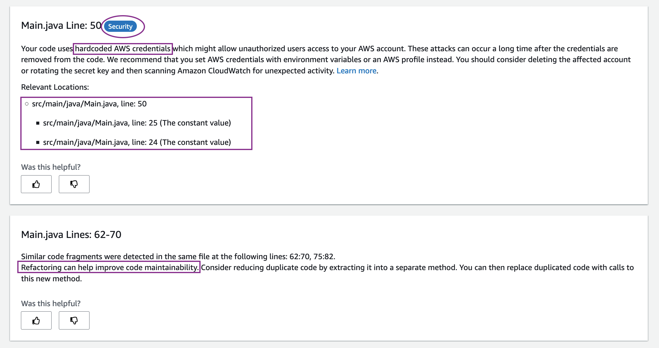
Secure coding practices
Python is often used for scripting. An integral part of such scripts is the use of subprocesses. As of this writing, CodeGuru Reviewer makes a limited, but important set of recommendations to make sure that your use of eval functions or subprocesses is secure from potential shell injections. It issues a warning if it detects that the command used in eval or subprocess scenarios might be influenced by external factors. For example, see the following code:
def execute(cmd):
    try:
        retcode = subprocess.call(cmd, shell=True)
        ...
    except OSError as e:
        ...
The following screenshot shows the CodeGuru Reviewer recommendation:

The developer accepted this recommendation and made the following fix.
def execute(cmd):
    try:
        retcode = subprocess.call(shlex.quote(cmd), shell=True)
        ...
    except OSError as e:
        ...
As shown in the preceding recommendations, not only are the code issues detected, but a detailed recommendation is also provided on how to fix the issues, along with a link to the Python official documentation. You can provide feedback on recommendations in the CodeGuru Reviewer console or by commenting on the code in a pull request. This feedback helps improve the performance of Reviewer so that the recommendations you see get better over time.
Now let’s take a look at CodeGuru Profiler.
CodeGuru Profiler for Python
Amazon CodeGuru Profiler analyzes your application’s performance characteristics and provides interactive visualizations to show you where your application spends its time. These visualizations a. k. a. flame graphs are a powerful tool to help you troubleshoot which code methods have high latency or are over utilizing your CPU.
Thanks to the new Python agent, you can now use CodeGuru Profiler on your Python applications to investigate performance issues.
The following list summarizes the supported versions as of this writing.
- AWS Lambda functions: Python3.8, Python3.7, Python3.6
- Other environments: Python3.9, Python3.8, Python3.7, Python3.6
Onboarding your Python application
For this post, let’s assume you have a Python application running on Amazon Elastic Compute Cloud (Amazon EC2) hosts that you want to profile. To onboard your Python application, complete the following steps:
1. Create a new profiling group in CodeGuru Profiler console called ProfilingGroupForMyApplication. Give access to your Amazon EC2 execution role to submit to this profiling group. See the documentation for details about how to create a Profiling Group.
2. Install the codeguru_profiler_agent module:
pip3 install codeguru_profiler_agent3. Start the profiler in your application.
An easy way to profile your application is to start your script through the codeguru_profiler_agent module. If you have an app.py script, use the following code:
python -m codeguru_profiler_agent -p ProfilingGroupForMyApplication app.pyAlternatively, you can start the agent manually inside the code. This must be done only one time, preferably in your startup code:
from codeguru_profiler_agent import Profiler

if __name__ == "__main__":
     Profiler(profiling_group_name='ProfilingGroupForMyApplication')
     start_application()    # your code in there....
Onboarding your Python Lambda function
Onboarding for an AWS Lambda function is quite similar.
- Create a profiling group called ProfilingGroupForMyLambdaFunction, this time we select “Lambda” for the compute platform. Give access to your Lambda function role to submit to this profiling group. See the documentation for details about how to create a Profiling Group.
- Include the codeguru_profiler_agent module in your Lambda function code.
- Add the with_lambda_profiler decorator to your handler function:
from codeguru_profiler_agent import with_lambda_profiler

@with_lambda_profiler(profiling_group_name='ProfilingGroupForMyLambdaFunction')
def handler_function(event, context):
      # Your code here
Alternatively, you can profile an existing Lambda function without updating the source code by adding a layer and changing the configuration. For more information, see Profiling your applications that run on AWS Lambda.
Profiling a Lambda function helps you see what is slowing down your code so you can reduce the duration, which reduces the cost and improves latency. You need to have continuous traffic on your function in order to produce a usable profile.
Viewing your profile
After running your profile for some time, you can view it on the CodeGuru console.

Each frame in the flame graph shows how much that function contributes to latency. In this example, an outbound call that crosses the network is taking most of the duration in the Lambda function, caching its result would improve the latency.
For more information, see Investigating performance issues with Amazon CodeGuru Profiler.
Supportability for CodeGuru Profiler is documented here.
If you don’t have an application to try CodeGuru Profiler on, you can use the demo application in the following GitHub repo.
Conclusion
This post introduced how to leverage CodeGuru Reviewer to identify hard-to-find code defects in various issue categories and how to onboard your Python applications or Lambda function in CodeGuru Profiler for CPU profiling. Combining both services can help you improve code quality for Python applications. CodeGuru is now available for you to try. For more pricing information, please see Amazon CodeGuru pricing.
About the Authors
 Neela Sawant is a Senior Applied Scientist in the Amazon CodeGuru team. Her background is building AI-powered solutions to customer problems in a variety of domains such as software, multimedia, and retail. When she isn’t working, you’ll find her exploring the world anew with her toddler and hacking away at AI for social good.
 Pierre Marieu is a Software Development Engineer in the Amazon CodeGuru Profiler team in London. He loves building tools that help the day-to-day life of other software engineers. Previously, he worked at Amadeus IT, building software for the travel industry.

Ran Fu is a Senior Product Manager in the Amazon CodeGuru team. He has a deep customer empathy, and love exploring who are the customers, what are their needs, and why those needs matter. Besides work, you may find him snowboarding in Keystone or Vail, Colorado.


 Raghavarao Sodabathina is an Enterprise Solutions Architect at AWS, focusing on Data Analytics, AI/ML, and Serverless Platform. He engages with customers to create innovative solutions that address customer business problems and accelerate the adoption of AWS services. In his spare time, Raghavarao enjoys spending time with his family, reading books, and watching movies.
 Siva Rajamani is a Boston-based Enterprise Solutions Architect for AWS. He enjoys working closely with customers, supporting their digital transformation and AWS adoption journey. His core areas of focus are Serverless, Application Integration, and Security. Outside of work, he enjoys outdoor activities and watching documentaries.


 Biff Gaut has been shipping software since 1983, from small startups to large IT shops. Along the way he has contributed to 2 books, spoken at several conferences and written many blog posts. He is now a Principal Solutions Architect at AWS working on the AWS Solutions Constructs team, helping customers deploy better architectures more quickly.


