Amazon Web Services (AWS) Cloud is elastic, convenient to use, easy to consume, and makes it simple to onboard workloads. Because of this simplicity, the cost associated with onboarding workloads is sometimes overlooked.
There is a notion that when an organization moves its workload to the cloud, agility, scalability, performance, and cost issues will disappear. While this may be true for agility and scalability, you must optimize your workload. You can do this with services like Amazon EC2 Auto Scaling via Amazon Elastic Compute Cloud (Amazon EC2) and Amazon EC2 Spot Instances to realize the performance and cost benefits the cloud offers.
In this blog post, we show you how Starburst Enterprise (Starburst) addressed a sudden increase in cost for their data analytics platform as they grew their internal teams and scaled out their infrastructure. After reviewing their architecture and deployments with AWS specialist architects, Starburst and AWS concluded that they could take the following steps to greatly reduce costs:
Use Spot Instances to run workloads.
Add Amazon EC2 Auto Scaling into their training and demonstration environments, because the Starburst platform is designed to elastically scale up and down.
For analytics workloads, when you rein in costs, you typically rein in performance. Starburst and AWS worked together to balance the cost and performance of Starburst’s data analytics platform while also harnessing the flexibility, scalability, security, and performance of the cloud.
What is Starburst Enterprise?
Starburst provides a Massively Parallel Processing SQL (MPPSQL) engine based on open source Trino. It is an analytics platform that provides the cornerstone in customers’ intelligent data mesh and offers the following benefits and services:
The platform gives you options for your data compute. You no longer have to wait on data migrations or extract, transform, and load (ETL), there is no vendor lock-in, and there is no need to swap out your existing analytics tools.
Starburst Stargate (Stargate) ensures that large jobs are completed within each data domain of your data mesh. Only the result set is retrieved from the domain.
Stargate reduces data output, which reduces costs and increases performance.
Data governance policies can also be applied uniquely in each data domain, ensuring security compliance and federation.
As shown in Figure 1, there are many connectors for input and output that ensure you experience improved performance and security.
Figure 1. Starburst platform
Integrating Starburst Enterprise with AWS
As shown in Figure 2, Starburst Enterprise uses AWS services to deliver elastic scaling and optimize cost. The platform is architected with decoupled storage and compute. This allows the platform to scale as needed to analyze petabytes of data.
Figure 2. Deployment architecture of Starburst platform on AWS
Amazon EC2 Auto Scaling
Enterprises have diverse analytic workloads; their compute and memory requirements vary with time. Starburst uses Amazon EKS and Amazon EC2 Auto Scaling to elastically scale compute resources to meet the demands of their analytics workloads.
Amazon EC2 Auto Scaling ensures that you have the compute capacity for your workloads to handle the load elastically. It is used to architect sophisticated, elastic, and resilient applications on the AWS Cloud.
Starburst uses the scheduled scaling feature of Amazon EC2 Auto Scaling to scale the cluster up/down based on time. Thus, they incur no costs when the cluster is not in use.
Amazon EKS is a fully managed Kubernetes service that allows you to run Kubernetes on AWS without needing to install, operate, and maintain your own Kubernetes control plane.
Scaling cloud resource consumption on demand has a major impact on controlling cloud costs. Starburst supports scaling down elastically, which means removing compute resources doesn’t impact the underlying processes.
Amazon EC2 Spot Instances
Spot Instances let you take advantage of unused EC2 capacity in the AWS Cloud. They are available at up to a 90% discount compared to On-Demand Instance prices. If EC2 needs capacity for On-Demand Instance usage, Spot Instances can be interrupted by Amazon EC2 with a two-minute notification. There are many ways to handle the interruption to ensure that the application is well architected for resilience and fault tolerance.
Starburst has integrated Spot Instances as a part of the Amazon EKS managed node groups to cost optimize the analytics workloads. This best practice of instance diversification is implemented by using the integration eksctl and instance selector with dry-run flag. This creates a list of instances of same size (vCPU/Mem ratio) and uses them in the underlying node groups.
Same size instances are required to make best use of Kubernetes Cluster Autoscaler, which is used to manage the size of the cluster.
Scaling down, handling interruptions, and provisioning compute
“Scaling in” an active application is tricky, but Starburst was built with resiliency in mind, and it can effectively manage shut downs.
Spot Instances are an ideal compute option because Starburst can handle potential interruptions natively. Starburst also uses Amazon EKS managed node groups to provision nodes in the cluster. This requires significantly less operational effort compared to using self-managed node groups. It allows Starburst to enforce best practices like capacity optimized allocation strategy, capacity rebalancing, and instance diversification.
When you need to “scale out” the deployment, Amazon EKS and Amazon EC2 Auto Scaling help to provision capacity, as depicted in Figure 3.
Figure 3. Depicting “scale out” in a Starburst deployment
Benefits realized from using AWS services
In a short period, Starburst was able to increase the number of people working on AWS. They added five times the number of Solutions Architects, they have previously. Additionally, in their initial tests of their new deployment architecture, their Solutions Architects were able to complete up to three times the amount of work than they had been able to previously. Even after the workload increased more than 15 times, with two simple changes they only had a slight increase in total cost.
This cost and performance optimization allows Starburst to be more productive internally and realize value for each dollar spent. This further justified investing more into building out infrastructure footprint.
Conclusion
In building their architecture with AWS, Starburst realized the importance of having a robust and comprehensive cloud administration plan that they can implement and manage going forward. They are now able to balance the cloud costs with performance and stability, even after considering the SLA requirements. Starburst is planning to teach their customers about the Spot Instance and Amazon EC2 Auto Scaling best practices to ensure they maintain a cost and performance optimized cloud architecture.
If you want to see the Starburst data analytics platform in action, you can get a free trial in the AWS Marketplace: Starburst Data Free Trial.
This blog post will demonstrate how to leverage Jenkins with Amazon Elastic Kubernetes Service (EKS) by running a Jenkins Manager within an EKS pod. In doing so, we can run Jenkins workloads by allowing Amazon EKS to spawn dynamic Jenkins Agent(s) in order to perform application and infrastructure deployment. Traditionally, customers will setup a Jenkins Manager-Agent architecture that contains a set of manually added nodes with no autoscaling capabilities. Implementing this strategy will ensure that a robust approach optimizes the performance with the right-sized compute capacity and work needed to successfully perform the build tasks.
In setting up our Amazon EKS cluster with Jenkins, we’ll utilize the eksctl simple CLI tool for creating clusters on EKS. Then, we’ll build both the Jenkins Manager and Jenkins Agent image. Afterward, we’ll run a container deployment on our cluster to access the Jenkins application and utilize the dynamic Jenkins Agent pods to run pipelines and jobs.
Solution Overview
The architecture below illustrates the execution steps.
Figure 1. Solution overview diagram
Disclaimer(s):(Note: This Jenkins application is not configured with a persistent volume storage. Therefore, you must establish and configure this template to fit that requirement).
To accomplish this deployment workflow, we will do the following:
Centralized Shared Services account
Deploy the Amazon EKS Cluster into a Centralized Shared Services Account.
Create the Amazon ECR Repository for the Jenkins Manager and Jenkins Agent to store docker images.
Deploy the kubernetes manifest file for the Jenkins Manager.
Target Account(s)
Establish a set of AWS Identity and Access Management (IAM) roles with permissions for cross-across access from the Share Services account into the Target account(s).
Jenkins Application UI
Jenkins Plugins – Install and configure the Kubernetes Plugin and CloudBees AWS Credentials Plugin from Manage Plugins (you will not have to manually install this since it will be packaged and installed as part of the Jenkins image build).
Jenkins Pipeline Example—Fetch the Jenkinsfile to deploy an S3 Bucket with CloudFormation in the Target account using a Jenkins parameterized pipeline.
Prerequisites
The following is the minimum requirements for ensuring this solution will work.
Account Prerequisites
Shared Services Account: The location of the Amazon EKS Cluster.
Target Account: The destination of the CI/CD pipeline deployments.
This blog provides a high-level overview of the best practices for cross-account deployment and isolation maintenance between the applications. We evaluated the cross-account application deployment permissions and will describe the current state as well as what to avoid. As part of the security best practices, we will maintain isolation among multiple apps deployed in these environments, e.g., Pipeline 1 does not deploy to the Pipeline 2 infrastructure.
Requirement
A Jenkins manager is running as a container in an EC2 compute instance that resides within a Shared AWS account. This Jenkins application represents individual pipelines deploying unique microservices that build and deploy to multiple environments in separate AWS accounts. The cross-account deployment utilizes the target AWS account admin credentials in order to do the deployment.
This methodology means that it is not good practice to share the account credentials externally. Additionally, the deployment errors risk should be eliminated and application isolation should be maintained within the same account.
Note that the deployment steps are being run using AWS CLIs, thus our solution will be focused on AWS CLI usage.
The risk is much lower when utilizing CloudFormation / CDK to conduct deployments because the AWS CLIs executed from the build jobs will specify stack names as parametrized inputs and the very low probability of stack-name error. However, it remains inadvisable to utilize admin credentials of the target account.
Best Practice — Current Approach
We utilized cross-account roles that can restrict unauthorized access across build jobs. Behind this approach, we will utilize the assume-role concept that will enable the requesting role to obtain temporary credentials (from the STS service) of the target role and execute actions permitted by the target role. This is safer than utilizing hard-coded credentials. The requesting role could be either the inherited EC2 instance role OR specific user credentials. However, in our case, we are utilizing the inherited EC2 instance role.
For ease of understanding, we will refer the target-role as execution-role below.
Figure 2. Current approach
As per the security best practice of assigning minimum privileges, we must first create execution role in IAM in the target account that has deployment permissions (either via CloudFormation OR via CLI’s), e.g., app-dev-role in Dev account and app-prod-role in Prod account.
For each of those roles, we configure a trust relationship with the parent account ID (Shared Services account). This enables any roles in the Shared Services account (with assume-role permission) to assume the execution-role and deploy it on respective hosting infrastructure, e.g., the app-dev-role in Dev account will be a common execution role that will deploy various apps across infrastructure.
Then, we create a local role in the Shared Services account and configure credentials within Jenkins to be utilized by the Build Jobs. Provide the job with the assume-role permissions and specify the list of ARNs across every account. Alternatively, the inherited EC2 instance role can also be utilized to assume the execution-role.
Create Cross-Account IAM Roles
Cross-account IAM roles allow users to securely access AWS resources in a target account while maintaining the observability of that AWS account. The cross-account IAM role includes a trust policy allowing AWS identities in another AWS account to assume the given role. This allows us to create a role in one AWS account that delegates specific permissions to another AWS account.
Create an IAM role with a common name in each target account. The role name we’ve created is AWSCloudFormationStackExecutionRole. The role must have permissions to perform CloudFormation actions and any actions regarding the resources that will be created. In our case, we will be creating an S3 Bucket utilizing CloudFormation.
This IAM role must also have an established trust relationship to the Shared Services account. In this case, the Jenkins Agent will be granted the ability to assume the role of the particular target account from the Shared Services account.
In our case, the IAM entity that will assume the AWSCloudFormationStackExecutionRole is the EKS Node Instance Role that associated with the EKS Cluster Nodes.
Build the custom docker images for the Jenkins Manager and the Jenkins Agent, and then push the images to AWS ECR Repository. Navigate to the docker/ directory, then execute the command according to the required parameters with the AWS account ID, repository name, region, and the build folder name jenkins-manager/ or jenkins-agent/ that resides in the current docker directory. The custom docker images will contain a set of starter package installations.
After building both images, navigate to the k8s/ directory, modify the manifest file for the Jenkins image, and then execute the Jenkins manifest.yaml template to setup the Jenkins application. (Note: This Jenkins application is not configured with a persistent volume storage. Therefore, you will need to establish and configure this template to fit that requirement).
# Fetch the Application URL or navigate to the AWS Console for the Load Balancer
kubectl get svc -n jenkins

# Verify that jenkins deployment/pods are up running
kubectl get pods -n jenkins

# Replace with jenkins manager pod name and fetch Jenkins login password
kubectl exec -it pod/<JENKINS-MANAGER-POD-NAME> -n jenkins -- cat /var/jenkins_home/secrets/initialAdminPassword
Click: Add a new cloud → select Kubernetes from the drop menus
Figure 4a. Jenkins Configure Nodes and Clouds
Note: Before proceeding, please ensure that you can access your Amazon EKS cluster information, whether it is through Console or CLI.
Enter a Name in the Kubernetes Cloud configuration field.
Enter the Kubernetes URL which can be found via AWS Console by navigating to the Amazon EKS service and locating the API server endpoint of the cluster, or run the command kubectl cluster-info.
Enter the namespace that will be utilized in the Kubernetes Namespace field. This will determine where the dynamic kubernetes pods will spawn. In our case, the name of the namespace is jenkins.
During the initial setup of Jenkins Manager on kubernetes, there is an environment variable JENKINS_URL that automatically utilizes the Load Balancer URL to resolve requests. However, we will resolve our requests locally to the cluster IP address.
The format is as follows: https://<service-name>.<namespace>.svc.cluster.local
Figure 4b. Configure Kubernetes Cloud
Set AWS Credentials
Security concerns are a key reason why we’re utilizing an IAM role instead of access keys. For any given approach involving IAM, it is the best practice to utilize temporary credentials.
You must have the AWS Credentials Binding Plugin installed before this step. Enter the unique ID name as shown in the example below.
Enter the IAM Role ARN you created earlier for both the ID and IAM Role to use in the field as shown below.
Figure 5. AWS Credentials Binding
Figure 6. Managed Credentials
Create a pipeline
Navigate to the Jenkins main menu and select new item
Create a Pipeline
Figure 7. Create a pipeline
Configure Jenkins Agent
Setup a Kubernetes YAML template after you’ve built the agent image. In this example, we will be using the k8sPodTemplate.yaml file stored in the k8s/ folder.
This deploy-stack.sh file can accept four different parameters and conduct several types of CloudFormation stack executions such as deploy, create-changeset, and execute-changeset. This is also reflected in the stages of this Jenkinsfile pipeline. As for the delete-stack.sh file, two parameters are accepted, and, when executed, it will delete a CloudFormation stack based on the given stack name and region.
In this Jenkinsfile, the individual pipeline build jobs will deploy individual microservices. The k8sPodTemplate.yaml is utilized to specify the kubernetes pod details and the inbound-agent that will be utilized to run the pipeline.
Click Build with Parameters and then select a build action.
Figure 8a. Build with Parameters
Examine the pipeline stages even further for the choice you selected. Also, view more details of the stages below and verify in your AWS account that the CloudFormation stack was executed.
Figure 8b. Pipeline Stage View
The Final Step is to execute your pipeline and watch the pods spin up dynamically in your terminal. As is shown below, the Jenkins agent pod spawned and then terminated after the work completed. Watch this task on your own by executing the following command:
# Watch the pods spawn in the "jenkins" namespace
kubectl get pods -n jenkins -w
In order to avoid incurring future charges, delete the resources utilized in the walkthrough.
Delete the EKS cluster. You can utilize the eksctl to delete the cluster.
Delete any remaining AWS resources created by EKS such as AWS LoadBalancer, Target Groups, etc.
Delete any related IAM entities.
Conclusion
This post walked you through the process of building out Amazon EKS based infrastructure and integrating Jenkins to orchestrate workloads. We demonstrated how you can utilize this to deploy securely across multiple accounts with dynamic Jenkins agents and create alignment to your business with similar use cases. To learn more about Amazon EKS, see our documentation pages or explore our console.
About the Authors
Vladimir P. Toussaint
Vladimir is a DevOps Cloud Architect at Amazon Web Services. He works with GovCloud customers to build solutions and capabilities as they move to the cloud. Previous to Amazon Web Services, Vladimir has leveraged container orchestration tools such as Kubernetes to securely manage microservice applications for large enterprises.
Matt Noyce
Matt is a Sr. Cloud Application Architect at Amazon Web Services. He works primarily with health care and life sciences customers to help them architect and build applications, data lakes, and DevOps pipelines that solve their business needs. In his spare time Matt likes to run and hike along with enjoying time with friends and family.
Nikunj Vaidya
Nikunj is a DevOps Tech Leader at Amazon Web Services. He offers technical guidance to the customers on AWS DevOps solutions and services that would streamline the application development process, accelerate application delivery, and enable maintaining a high bar of software quality. Prior to AWS, Nikunj has worked in software engineering roles, leading transformation projects, driving releases and improvements in the software quality and customer experience.
As a manufacturing enterprise, maximizing your operational efficiency and optimizing output are critical factors in this competitive global market. However, many manufacturers are unable to frequently collect data, link data together, and generate insights to help them optimize performance. Furthermore, decades of competing standards for connectivity have resulted in the lack of universal protocols to connect underlying equipment and assets.
Machine to Cloud Connectivity Framework (M2C2) is an Amazon Web Services (AWS) Solution that provides the secure ingestion of equipment telemetry data to the AWS Cloud. This allows you to use AWS services to conduct analysis on your equipment data, instead of managing underlying infrastructure operations. The solution allows for robust data ingestion from industrial equipment that use OPC Data Access (OPC DA) and OPC Unified Access (OPC UA) protocols.
Secure, automated configuration and ingestion of industrial data
M2C2 allows manufacturers to ingest their shop floor data into various data destinations in AWS. These include AWS IoT SiteWise, AWS IoT Core, Amazon Kinesis Data Streams, and Amazon Simple Storage Service (S3). The solution is integrated with AWS IoT SiteWise so you can store, organize, and monitor data from your factory equipment at scale. Additionally, the solution provides customers an intuitive user interface to create, configure, monitor, and manage connections.
Automated setup and configuration
Figure 1. Automatically create and configure connections
With M2C2, you can connect to your operational technology assets (see Figure 1). The solution automatically creates AWS IoT certificates, keys, and configuration files for AWS IoT Greengrass. This allows you to set up Greengrass to run on your industrial gateway. It also automates the deployment of any Greengrass group configuration changes required by the solution. You can define a connection with the interface, and specify attributes about equipment, tags, protocols, and read frequency for equipment data.
Figure 2. Send data to different destinations in the AWS Cloud
Once the connection details have been specified, you can send data to different destinations in AWS Cloud (see Figure 2). M2C2 provides capability to ingest data from industrial equipment using OPC-DA and OPC-UA protocols. The solution collects the data, and then publishes the data to AWS IoT SiteWise, AWS IoT Core, or Kinesis Data Streams.
Publishing data to AWS IoT SiteWise allows for end-to-end modeling and monitoring of your factory floor assets. When using the default solution configuration, publishing data to Kinesis Data Streams allows for ingesting and storing data in an Amazon S3 bucket. This gives you the capability for custom advanced analytics use cases and reporting.
You can choose to create multiple connections, and specify sites, areas, processes, and machines, by using the setup UI.
Management of connections and messages
Figure 3. Manage your connections
M2C2 provides a straightforward connections screen (see Figure 3), where production managers can monitor and review the current state of connections. You can start and stop connections, view messages and errors, and gain connectivity across different areas of your factory floor. The Manage connections UI allows you to holistically manage data connectivity from a centralized place. You can then make changes and corrections as needed.
Architecture and workflow
Figure 4. Machine to Cloud Connectivity (M2C2) Framework architecture
The AWS CloudFormation template deploys the following infrastructure, shown in Figure 4:
An Amazon CloudFront user interface that deploys into an Amazon S3 bucket configured for web hosting.
An Amazon API Gateway API provides the user interface for client requests.
An Amazon Cognito user pool authenticates the API requests.
AWS Lambda functions power the user interface, in addition to the configuration and deployment mechanism for AWS IoT Greengrass and AWS IoT SiteWise gateway resources. Amazon DynamoDB tables store the connection metadata.
An AWS IoT SiteWise gateway configuration can be used for any OPC UA data sources.
An Amazon Kinesis Data Streams data stream, Amazon Kinesis Data Firehose, and Amazon S3 bucket to store telemetry data.
AWS IoT Greengrass is installed and used on an on-premises industrial gateway to run protocol connector Lambda functions. These connect and read telemetry data from your OPC UA and OPC DA servers.
Lambda functions are deployed onto AWS IoT Greengrass Core software on the industrial gateway. They connect to the servers and send the data to one or more configured destinations.
Lambda functions that collect the telemetry data write to AWS IoT Greengrass stream manager streams. The publisher Lambda functions read from the streams.
Publisher Lambda functions forward the data to the appropriate endpoint.
Data collection
The Machine to Cloud Connectivity solution uses Lambda functions running on Greengrass to connect to your on-premises OPC-DA and OPC-UA industrial devices. When you deploy a connection for an OPC-DA device, the solution configures a connection-specific OPC-DA connector Lambda. When you deploy a connection for an OPC-UA device, the solution uses the AWS IoT SiteWise Greengrass connector to collect the data.
Regardless of protocol, the solution configures a publisher Lambda function, which takes care of sending your streaming data to one or more desired destinations. Stream Manager enables the reading and writing of stream data from multiple sources and to multiple destinations within the Greengrass core. This enables each configured collector to write data to a stream. The publisher reads from that stream and sends the data to your desired AWS resource.
Conclusion
Machine to Cloud Connectivity (M2C2) Framework is a self-deployable solution that provides secure connectivity between your technology (OT) assets and the AWS Cloud. With M2C2, you can send data to AWS IoT Core or AWS IoT SiteWise for analytics and monitoring. You can store your data in an industrial data lake using Kinesis Data Streams and Amazon S3. Get started with Machine to Cloud Connectivity (M2C2) Framework today.
One of the great advantages of cloud computing is that you have access to programmable infrastructure. This allows you to manage your infrastructure as code and apply the same practices of application code development to infrastructure provisioning.
AWS CloudFormation gives you an easy way to model a collection of related AWS and third-party resources, provision them quickly and consistently, and manage them throughout their lifecycles. A CloudFormation template describes your desired resources and their dependencies so you can launch and configure them together as a stack. You can use a template to create, update, and delete an entire stack as a single unit instead of managing resources individually.
When you create or update a stack, your action might fail for different reasons. For example, there can be errors in the template, in the parameters of the template, or issues outside the template, such as AWS Identity and Access Management (IAM) permission errors. When such an error occurs, CloudFormation rolls back the stack to the previous stable condition. For a stack creation, that means deleting all resources created up to the point of the error. For a stack update, it means restoring the previous configuration.
This rollback to the previous state is great for production environments, but doesn’t make it easy to understand the reason for the error. Depending on the complexity of your template and the number of resources involved, you might spend lots of time waiting for all the resources to roll back before you can update the template with the right configuration and retry the operation.
Today, I am happy to share that now CloudFormation allows you to disable the automatic rollback, keep the resources successfully created or updated before the error occurs, and retry stack operations from the point of failure. In this way, you can quickly iterate to fix and remediate errors and greatly reduce the time required to test a CloudFormation template in a development environment. You can apply this new capability when you create a stack, when you update a stack, and when you execute a change set. Let’s see how this works in practice.
AWSTemplateFormatVersion: "2010-09-09"
Description: A sample template to fix & remediate
Parameters:
  ShardCountParameter:
    Type: Number
    Description: The number of shards for the Kinesis stream
Resources:
  MyBucket:
    Type: AWS::S3::Bucket
  MyQueue:
    Type: AWS::SQS::Queue
  MyStream:
    Type: AWS::Kinesis::Stream
    Properties:
      ShardCount: !Ref ShardCountParameter
  MyTable:
    Type: AWS::DynamoDB::Table
    Properties:
      BillingMode: PAY_PER_REQUEST
      AttributeDefinitions:
        - AttributeName: "ArtistId"
          AttributeType: "S"
        - AttributeName: "Concert"
          AttributeType: "S"
        - AttributeName: "TicketSales"
          AttributeType: "S"
      KeySchema:
        - AttributeName: "ArtistId"
          KeyType: "HASH"
        - AttributeName: "Concert"
          KeyType: "RANGE"
      KinesisStreamSpecification:
        StreamArn: !GetAtt MyStream.Arn
Outputs:
  BucketName:
    Value: !Ref MyBucket
    Description: The name of my S3 bucket
  QueueName:
    Value: !GetAtt MyQueue.QueueName
    Description: The name of my SQS queue
  StreamName:
    Value: !Ref MyStream
    Description: The name of my Kinesis stream
  TableName:
    Value: !Ref MyTable
    Description: The name of my DynamoDB table
Now, I want to create a stack from this template. On the CloudFormation console, I choose Create stack. Then, I upload the template file and choose Next.
I enter a name for the stack. Then, I fill the stack parameters. My template file has one parameter (ShardCountParameter) used to configure the number of shards for the Kinesis data stream. I know that the number of shards should be greater or equal to one, but by mistake, I enter zero and choose Next.
To create, modify, or delete resources in the stack, I use an IAM role. In this way, I have a clear boundary for the permissions that CloudFormation can use for stack operations. Also, I can use the same role to automate the deployment of the stack later in a standardized and reproducible environment.
In Permissions, I select the IAM role to use for the stack operations.
Now it’s time to use the new feature! In the Stack failure options, I select Preserve successfully provisioned resources to keep, in case of errors, the resources that have already been created. Failed resources are always rolled back to the last known stable state.
I leave all other options at their defaults and choose Next. Then, I review my configurations and choose Create stack.
The creation of the stack is in progress for a few seconds, and then it fails because of an error. In the Events tab, I look at the timeline of the events. The start of the creation of the stack is at the bottom. The most recent event is at the top. Properties validation for the stream resource failed because the number of shards (ShardCount) is below the minimum. For this reason, the stack is now in the CREATE_FAILED status.
Because I chose to preserve the provisioned resources, all resources created before the error are still there. In the Resources tab, the S3 bucket and the SQS queue are in the CREATE_COMPLETE status, while the Kinesis data stream is in the CREATE_FAILED status. The creation of the DynamoDB table depends on the Kinesis data stream to be available because the table uses the data stream in one of its properties (KinesisStreamSpecification). As a consequence of that, the table creation has not started yet, and the table is not in the list.
The rollback is now paused, and I have a few new options:
Retry – To retry the stack operation without any change. This option is useful if a resource failed to provision due to an issue outside the template. I can fix the issue and then retry from the point of failure.
Update – To update the template or the parameters before retrying the stack creation. The stack update starts from where the last operation was interrupted by an error.
Rollback – To roll back to the last known stable state. This is similar to default CloudFormation behavior.
Fixing Issues in the Parameters I quickly realize the mistake I made while entering the parameter for the number of shards, so I choose Update.
I don’t need to change the template to fix this error. In Parameters, I fix the previous error and enter the correct amount for the number of shards: one shard.
I leave all other options at their current values and choose Next.
In Change set preview, I see that the update will try to modify the Kinesis stream (currently in the CREATE_FAILED status) and add the DynamoDB table. I review the other configurations and choose Update stack.
Now the update is in progress. Did I solve all the issues? Not yet. After some time, the update fails.
Fixing Issues Outside the Template The Kinesis stream has been created, but the IAM role assumed by CloudFormation doesn’t have permissions to create the DynamoDB table.
In the IAM console, I add additional permissions to the role used by the stack operations to be able to create the DynamoDB table.
Back to the CloudFormation console, I choose the Retry option. With the new permissions, the creation of the DynamoDB table starts, but after some time, there is another error.
Fixing Issues in the Template This time there is an error in my template where I define the DynamoDB table. In the AttributeDefinitions section, there is an attribute (TicketSales) that is not used in the schema.
With DynamoDB, attributes defined in the template should be used either for the primary key or for an index. I update the template and remove the TicketSales attribute definition.
Because I am editing the template, I take the opportunity to also add MinValue and MaxValue properties to the number of shards parameter (ShardCountParameter). In this way, CloudFormation can check that the value is in the correct range before starting the deployment, and I can avoid further mistakes.
I select the Update option. I choose to update the current template, and I upload the new template file. I confirm the current values for the parameters. Then, I leave all other options to their current values and choose Update stack.
This time, the creation of the stack is successful, and the status is UPDATE_COMPLETE. I can see all resources in the Resources tab and their description (based on the Outputs section of the template) in the Outputs tab.
Here’s the final version of the template:
AWSTemplateFormatVersion: "2010-09-09"
Description: A sample template to fix & remediate
Parameters:
  ShardCountParameter:
    Type: Number
    MinValue: 1
    MaxValue: 10
    Description: The number of shards for the Kinesis stream
Resources:
  MyBucket:
    Type: AWS::S3::Bucket
  MyQueue:
    Type: AWS::SQS::Queue
  MyStream:
    Type: AWS::Kinesis::Stream
    Properties:
      ShardCount: !Ref ShardCountParameter
  MyTable:
    Type: AWS::DynamoDB::Table
    Properties:
      BillingMode: PAY_PER_REQUEST
      AttributeDefinitions:
        - AttributeName: "ArtistId"
          AttributeType: "S"
        - AttributeName: "Concert"
          AttributeType: "S"
      KeySchema:
        - AttributeName: "ArtistId"
          KeyType: "HASH"
        - AttributeName: "Concert"
          KeyType: "RANGE"
      KinesisStreamSpecification:
        StreamArn: !GetAtt MyStream.Arn
Outputs:
  BucketName:
    Value: !Ref MyBucket
    Description: The name of my S3 bucket
  QueueName:
    Value: !GetAtt MyQueue.QueueName
    Description: The name of my SQS queue
  StreamName:
    Value: !Ref MyStream
    Description: The name of my Kinesis stream
  TableName:
    Value: !Ref MyTable
    Description: The name of my DynamoDB table
This was a simple example, but the new capability to retry stack operations from the point of failure already saved me lots of time. It allowed me to fix and remediate issues quickly, reducing the feedback loop and increasing the number of iterations that I can do in the same amount of time. In addition to using this for debugging, it is also great for incremental interactive development of templates. With more sophisticated applications, the time saved will be huge!
Fix and Remediate a CloudFormation Stack Using the AWS CLI I can preserve successfully provisioned resources with the AWS Command Line Interface (CLI) by specifying the --disable-rollback option when I create a stack, update a stack, or execute a change set. For example:
I can now update stacks in the CREATE_FAILED or UPDATE_FAILED status. To manually roll back a stack that is in the CREATE_FAILED or UPDATE_FAILED status, I can use the new rollback stack command:
Availability and Pricing The capability for AWS CloudFormation to retry stack operations from the point of failure is available at no additional charge in the following AWS Regions: US East (N. Virginia, Ohio), US West (Oregon, N. California), AWS GovCloud (US-East, US-West), Canada (Central), Europe (Frankfurt, Ireland, London, Milan, Paris, Stockholm), Asia Pacific (Hong Kong, Mumbai, Osaka, Seoul, Singapore, Sydney, Tokyo), Middle East (Bahrain), Africa (Cape Town), and South America (São Paulo).
Do you prefer to define your cloud application resources using familiar programming languages such as JavaScript, TypeScript, Python, Java, C#, and Go? Good news! The AWS Cloud Development Kit (AWS CDK) team is planning to add support for the new capabilities described in this post in the next couple of weeks.
This post is written by Dathu Patil, Solutions Architect and Naomi Joshi, Cloud Application Architect.
AWS CloudFormation custom resources allow you to write custom provisioning logic in templates. These run anytime you create, update, or delete stacks. Using AWS Lambda-backed custom resources, you can associate a Lambda function with a CloudFormation custom resource. The function is invoked whenever the custom resource is created, updated, or deleted.
When CloudFormation asynchronously invokes the function, it passes the request data, such as the request type and resource properties to the function. The customizability of Lambda functions in combination with CloudFormation allow a wide range of scenarios. For example, you can dynamically look up Amazon Machine Image (AMI) IDs during stack creation or use utilities such as string reversal functions.
Unhandled exceptions or transient errors in the custom resource Lambda function can cause your code to exit without sending a response. CloudFormation requires an HTTPS response to confirm if the operation is successful or not. An unreported exception causes CloudFormation to wait until the operation times out before starting a stack rollback.
If the exception occurs again on rollback, CloudFormation waits for a timeout exception before ending in a rollback failure. During this time, your stack is unusable. You can learn more about this and best practices by reviewing Best Practices for CloudFormation Custom Resources.
In this blog, you learn how you can use Amazon SQS and Lambda to add resiliency to your Lambda-backed CloudFormation custom resource deployments. The example shows how to use CloudFormation custom resource to look up an AMI ID dynamically during Amazon EC2 creation.
Overview
CloudFormation templates that declare an EC2 instance must also specify an AMI ID. This includes an operating system and other software and configuration information used to launch the instance. The correct AMI ID depends on the instance type and Region in which you’re launching your stack. AMI ID can change regularly, such as when an AMI is updated with software updates.
Customers often implement a CloudFormation custom resource to look up an AMI ID while creating an EC2 instance. In this example, the lookup Lambda function calls the EC2 API. It fetches the available AMI IDs, uses the latest AMI ID, and checks for a compliance tag. This implementation assumes that there are separate processes for creating AMI and running compliance checks. The process that performs compliance and security checks creates a compliance tag on a successful scan.
This solution shows how you can use SQS and Lambda to add resiliency to handle an exception. In this case, the exception occurs in the AMI lookup custom resource due to a missing compliance tag. When the AMI lookup function fails processing, it uses the Lambda destination configuration to send the request to an SQS queue. The message is reprocessed using the SQS queue and Lambda function.
The CloudFormation custom resource asynchronously invokes the AMI lookup Lambda function to perform appropriate actions.
The AMI lookup Lambda function calls the EC2 API to fetch the list of AMIs and checks for a compliance tag. If the tag is missing, it throws an unhandled exception.
On failure, the Lambda destination configuration sends the request to the retry queue that is configured as a dead-letter queue (DLQ). SQS adds a custom delay between retry processing to support more than two retries.
The retry Lambda function processes messages in the retry queue using Lambda with SQS. Lambda polls the queue and invokes the retry Lambda function synchronously with an event that contains queue messages.
The retry function then synchronously invokes the AMI lookup function using the information from the request SQS message.
The AMI Lookup Lambda function
An AWS Serverless Application Model (AWS SAM) template is used to create the AMI lookup Lambda function. You can configure async event options such as number of retries on the Lambda function. The maximum retries allowed is 2 and there is no option to set a delay between the invocation attempts.
When a transient failure or unhandled error occurs, the request is forwarded to the retry queue. This part of the AWS SAM template creates AMI lookup Lambda function:
This function calls the EC2 API using the boto3 AWS SDK for Python. It calls the describe_images method to get a list of images with given filter conditions. The Lambda function iterates through the AMI list and checks for compliance tags. If the tag is not present, it raises an exception:
ec2_client = boto3.client('ec2', region_name=region)
         # Get AMI IDs with the specified name pattern and owner
         describe_response = ec2_client.describe_images(
            Filters=[{'Name': "name", 'Values': architectures},
                     {'Name': "tag-key", 'Values': ['ami-compliance-check']}],
            Owners=["amazon"]
        )
The queue and the retry Lambda function
The retry queue adds a 60-second delay before a message is available for the processing. The time delay between retry processing attempts provides time for transient errors to be corrected. This is the AWS SAM template for creating these resources:
The retry Lambda function periodically polls for new messages in the retry queue. The function synchronously invokes the AMI lookup Lambda function. On success, a response is sent to CloudFormation. This process runs until the AMI lookup function returns a successful response or the message is deleted from the SQS queue. The deletion is based on the MessageRetentionPeriod, which is set to 600 seconds in this case.
for record in event['Records']:
        body = json.loads(record['body'])
        response = client.invoke(
            FunctionName=body['requestContext']['functionArn'],
            InvocationType='RequestResponse',
            Payload=json.dumps(body['requestPayload']).encode()
        )
An existing Amazon EC2 public image. You can choose any of the AMIs from the AWS Management Console with Architecture = X86_64 and Owner = amazon for test purposes. Note the AMI ID.
Download the source code from the resilient-cfn-custom-resource GitHub repository. The template.yaml file is an AWS SAM template. It deploys the Lambda functions, SQS, and IAM roles required for the Lambda function. It uses Python 3.8 as the runtime and assigns 128 MB of memory for the Lambda functions.
To build and deploy this application using the AWS SAM CLI build and guided deploy:
sam build --use-container
sam deploy --guided
The custom resource stack creation invokes the AMI lookup Lambda function. This fetches the AMI ID from all public EC2 images available in your account with the tag ami-compliance-check. Typically, the compliance tags are created by a process that performs security scans.
In this example, the security scan process is not running and the tag is not yet added to any AMIs. As a result, the custom resource throws an exception, which goes to the retry queue. This is retried by the retry function until it is successfully processed.
Use the console or AWS CLI to add the tag to the chosen EC2 AMI. In this example, this is analogous to a separate governance process that checks for AMI compliance and adds the compliance tag if passed. Replace the $AMI-ID with the AMI ID captured in the prerequisites:
After the tags are added, a response is sent successfully from the custom resource Lambda function to the CloudFormation stack. It includes your $AMI-ID and a test EC2 instance is created using that image. The stack creation completes successfully with all resources deployed.
Conclusion
This blog post demonstrates how to use SQS and Lambda to add resiliency to CloudFormation custom resources deployments. This solution can be customized for use cases where CloudFormation stacks have a dependency on a custom resource.
CloudFormation custom resource failures can happen due to unhandled exceptions. These are caused by issues with a dependent component, internal service, or transient system errors. Using this solution, you can handle the failures automatically without the need for manual intervention. To get started, download the code from the GitHub repo and start customizing.
For more serverless learning resources, visit Serverless Land.
FireEye Helix is a security operations platform that allows organizations to take control of any incident from detection to response. FireEye Helix detects security incidents by correlating logs and configuration settings from sources like VPC Flow Logs, AWS CloudTrail, and Security groups.
In this blog post, we will discuss an architecture that allows you to create custom analytics dashboards with Amazon QuickSight. These dashboards are based on the threat detection logs collected by FireEye Helix. We automate this process so that data can be pulled and ingested based on a provided schedule. This approach uses AWS Lambda, and Amazon Simple Storage Service (Amazon S3) in addition to QuickSight.
Architecture Overview
The solution outlines how to ingest the security log data from FireEye Helix to Amazon S3 and create QuickSight visualizations from the log data. With this approach, you need Amazon EventBridge to invoke a Lambda function to connect to the FireEye Helix API. There are two steps to this process:
Download the log data from FireEye Helix and store it in Amazon S3.
Create a visualization Dashboard in QuickSight.
The architecture shown in Figure 1 represents the process we will walk through in this blog post. To implement this solution, you will need the following AWS services and features involved:
The following items are required to get your environment set up for this walkthrough.
AWS account.
FireEye Helix search alerts API endpoint. This is available under the API documentation in the FireEye Helix console.
FireEye Helix API key. This FireEye community page explains how to generate an API key with appropriate permissions (always follow least privilege principles). This key is used by the Lambda function to periodically fetch alerts.
Extract the data from FireEye Helix and load it into Amazon S3
You will use the following high-level steps to retrieve the necessary security log data from FireEye Helix and store it on Amazon S3 to make it available for QuickSight.
Establish an AWS Identity and Access Management (IAM) role for the Lambda function. It must have permissions to access Secrets Manager and Amazon S3 so they can retrieve the FireEye Helix API key and store the extracted data, respectively.
Create an Amazon S3 bucket to store the FireEye Helix security log data.
Create a Lambda function that uses the API key from Secrets Manager, calls the FireEye Helix search alerts API to extract FireEye Helix’s threat detection logs, and stores the data in the S3 bucket.
To simplify this deployment, we have developed a CloudFormationtemplate to automate creating the preceding requirements. Follow the below steps to deploy the template:
Select “Upload a template file” radio button, click on “Choose file” button, and select “helix-dashboard.yaml” file in the downloaded Github repository. Click “Next” to proceed.
On “Specify stack details” screen enter the parameters shown in Figure 2.
Figure 2: CloudFormation stack creation with initial parameters
The parameters in Figure 2 include:
HelixAPISecretName – Enter the Secrets Manager secret name where the FireEye Helix API key is stored.
HelixEndpointUrl – Enter the Helix search API endpoint URL.
Amazon S3 bucket – Enter the bucket prefix (a random suffix will be added to make it unique).
Schedule – Choose the default option that pulls logs once a day, or enter the CloudWatch event schedule expression.
Select the check box next to “I acknowledge that AWS CloudFormation might create IAM resources.” and then press the Create Stack button. After the CloudFormation stack completes, you will have a fully functional process that will retrieve the FireEye Helix security log data and store it on the S3 bucket.
You can also select the Lambda function from the CloudFormation stack outputs to navigate to the Lambda console. Review the following default code, and add any additional transformation logic according to your needs after fetching the results (line 32).
import boto3
from datetime import datetime
import requests
import os

region_name = os.environ['AWS_REGION']
secret_name = os.environ['APIKEY_SECRET_NAME']
bucket_name = os.environ['S3_BUCKET_NAME']
helix_api_url = os.environ['HELIX_ENDPOINT_URL']

def lambda_handler(event, context):

    now = datetime.now()
    # Create a Secrets Manager client to fetch API Key from Secrets Manager
    session = boto3.session.Session()
    client = session.client(
        service_name='secretsmanager',
        region_name=region_name
    )
    apikey = client.get_secret_value(
            SecretId=secret_name
        )['SecretString']

    datestr = now.strftime("%B %d, %Y")
    apiheader = {'x-fireeye-api-key': apikey}

    try:
        # Call Helix Rest API to fetch the Alerts
        helixalerts = requests.get(
            f'{helix_api_url}?format=csv&query=start:"{datestr}" end:"{datestr}" class=alerts', headers=apiheader)

        # Optionally transform the content according to your needs..

        # Create a S3 client to upload the CSV file
        s3 = boto3.client('s3')
        path = now.strftime("%Y/%m/%d")+'/alerts-'+now.strftime("%H-%M-%S")+'.csv'
        response = s3.put_object(
            Body=helixalerts.content,
            Bucket=bucket_name,
            Key=path,
        )
        print('S3 upload response:', response)
    except Exception as e:
        print('error while fetching the alerts', e)
        raise e

    return {
        'statusCode': 200,
        'body': f'Successfully fetched alerts from Helix and uploaded to {path}'
    }
Creating a visualization in QuickSight
Once the FireEye data is ingested into an S3 bucket, you can start creating custom reports and dashboards using QuickSight. Following is a walkthrough on how to create a visualization in QuickSight based on the data that was ingested from FireEye Helix.
Step 1 – When placing the FireEye data into Amazon S3, ensure you have a clean directory structure so you can partition your data. By partitioning your data, you can restrict the amount of data scanned by each query, thus improving performance and reducing cost. The following is a sample directory structure you could use.
ssw-fireeye-logs
2021
04
05
The following is an example of what the data will look like after it is ingested from FireEye Helix into your Amazon S3 bucket. In this blog post, we will use the Alert_Desc column to report on the types of common attacks.
Step 2 – Next, you must create a manifest file that will instruct QuickSight how to read the FireEye log files on Amazon S3. The preceding example is a manifest file that instructs QuickSight to recursively search for files in the ssw-fireeye-logs bucket, and can be seen in the URIPrefixes section. The GlobalUploadSettings section informs QuickSight the type and format of files it will read.
Step 3 – Open Amazon QuickSight. Use the AWS Management Console and search for QuickSight.
Step 4 – Below the QuickSight logo, find and select Datasets.
Step 5 – Push the blue New dataset button.
Step 6 – Now you are on Create a Dataset page which enables you to select a data source you would like QuickSight to ingest. Because we have stored the FireEye Helix data on S3, you should choose the S3 data source.
Step 7 – A pop-up box will appear called New S3 data source. Type a data source name, and upload the manifest file you created. Next, push the Connect button.
Step 8 – You are now directed to the Visualize screen. For this exercise let’s choose a Pie chart, you can find this in the Visual types section by hovering over each icon and reading each tool tip that comes up. Look for the tool tip that says Pie chart. After selecting the Pie Chart visual type, two entries in the Field wells section at the top of the screen will show up called Group/Color and Value. Click the drop down in Group/Color and select the Alert_Desc column. Now click the drop down in Value and also select Alter_Desc column but choose count as an aggregate. This will create an informative visualization of the most common attacks based on the sample data shown previously in Step 1.
Figure 3: Visualization screen in QuickSight
Clean up
If you created any resources in AWS for this solution, consider removing them and any example resources you deployed. This includes the FireEye Helix API keys, S3 buckets, Lambda functions, and QuickSight visualizations. This helps ensure that there are no unwanted recurring charges. For more information, review how to delete the CloudFormation stack.
Conclusion
This blog post showed you how to ingest security log data from FireEye Helix and store that data in Amazon S3. We also showed you how to create your own visualizations in QuickSight to better understand the overall security posture of your AWS environment. With this solution, you can perform deep analysis and share these insights among different audiences in your organization (such as, operations, security, and executive management).
Field Notes provides hands-on technical guidance from AWS Solutions Architects, consultants, and technical account managers, based on their experiences in the field solving real-world business problems for customers.
The Open Microscopy Environment (OME) consortium develops open-source software and format standards for microscopy data. OME Remote Objects (OMERO) is an open source, image data management platform designed to support digital pathology and cellular biology studies. You can access, share, and work with various biological data. This can include histopathology, high content screening, electron microscopy, and even non-image genotype data. Deploying this open source tool on Amazon Web Services (AWS) allows you to access your image data in a secure central repository. You can take advantage of elastic storage by growing the archive as needed without provisioning excess storage beforehand. OMERO has a web interface, which facilitates data access and visualization. It also supports connection through the OMERO client or other third-party image analysis tools, like CellProfilerTM, QuPath, Fiji, ImageJ, and others.
The challenge of microscopy data
Saint Louis University (SLU) School of Medicine Research Microscopy and Histology Core required a centralized system for both distribution and hosting. The solution must provide research imaging distribution to both internal and external clients. It also needed the capability of hosting an educational platform for microscope images. SLU decided that the open source software OMERO was an ideal fit for them.
In order to provide speed, ease of access, and security for the University’s computer networks, SLU decided the solution must be hosted in the cloud. By partnering with AWS, SLU established a robust system for their clients. The privately hosted images on OMERO represent research material databases used by University researchers. OMERO also hosts teaching datasets for resident and fellow education. Other publicly hosted repositories provide access to source images for future publishing standards and regulations. SLU reported that the implementation was extraordinarily smooth for a non-programmer. In addition, the system design allowed for advanced data management to control costs and security.
Reviewing the OMERO architecture
OMERO is a typical three-tier web application, consisting of the following components:
OMERO.web provides access to OMERO’s data hierarchies and also enables annotation, organization, and visualization of data. This web browser-based client of OMERO.server exposes the annotation-based data-sharing mechanism.
OMERO.server is a middleware server application that provides access to image data and metadata stored in a series of databases. It contains a multi-threaded, image-rendering engine and supports a wide range (>140) of image pyramid formats through the Bio-Formats Java library. This Java application facilitates remote access and interoperability for modern scientific studies. It also exposes an API to allow any OMERO client to access the original data and any derived measurements.
OMERO relational database (PostgreSQL) provides the underlying storage facilities. This storage backend contains the processed metadata associated with the binary images, measurement specification, user information, structured annotations, and more.
Figure 1. Architectural diagram for a highly available (HA) deployment of OMERO on AWS including data ingestion options
To achieve the highly available (HA) deployment in the diagram, follow the guidance from this GitHub repository. Since OMERO only supports one writer per mounted network file share, there is one OMERO read+write server and one read-only server in the HA deployment. Otherwise, multiple instances will compete to get first access to Amazon Elastic File System (EFS). If HA is not a requirement, you can lower costs by deploying only the read+write OMERO.server.
OMERO is deployed on AWS using AWS CloudFormation (CFN) templates, which will deploy two nested CFN stacks, one for storage, and one for compute. The storage template creates an EFS volume and an Amazon Relational Database Service (RDS) instance of PostgreSQL. EFS provides the option to move files to an infrequent accessed storage class after a certain number of days to save storage cost. RDS has Multi-AZ option to improve business continuity. The compute template creates Amazon Elastic Container Service (Amazon ECS) containers for the OMERO web and server functions. You have the option to deploy the OMERO containers on AWS Fargate or Amazon EC2 launch type. It also creates an Amazon Application Load Balancer (ALB) with duration-based stickiness enabled and an AWS Certificate Manager (ACM) certificate for Transport Layer Security (TLS) termination at ALB. Only the ALB is publicly accessible, as the web portal is protected behind it in private subnets. VPC and subnets are required, which can be obtained via this CFN template. It also requires the hosted zone ID and fully qualified domain name in Amazon Route 53, which will be used to validate the TLS certificate. If higher security is not a requirement, there is an option to deploy without the registered domain and the hosted zone in Route 53. You will then be able to access the OMERO web through Application Load Balancer DNS name without TLS encryption.
Additionally, the containers of OMERO.web and OMERO.server can be extended with plugins. The landing page for login can be customized with logos, brands, or disclaimers. Build a new Docker container image with specific configuration changes to enrich the functionality of this open source platform.
You can use Amazon ECS Exec to access the OMERO command line interface (CLI) to import images within the OMERO.server container, running on either AWS Fargate or EC2 launch type. You can also run Amazon ECS Exec via AWS CloudShell. The OMERO CFN templates enable Amazon ECS Exec commands by default. You will only need to install AWS CLI and SSM plugin on your clients or AWS CloudShell to initiate the commands. When you import images within the OMERO.server container instances, you can use the OMERO in-place import to avoid redundant copies of the image files on Amazon EFS. Alternatively, you can access the Windows desktop OMERO client OMERO.insight, via the application virtualization service Amazon AppStream 2.0. This connects to the OMERO.server in the same VPC. Amazon AppStream 2.0 allows Amazon S3 being used as home folder storage, so you can import images directly from Amazon S3 to OMERO.server.
AWS offers multiple options to move your microscopic image data from on premises facilities to the cloud storage, as illustrated in Figure 1:
Researchers and scientists at St. Louis University were able to grow their image repository on AWS without the concern of fixed storage limits. They can scale their compute environment up or down as their research requirements dictate. The managed services, like Amazon ECS and RDS, are able to significantly reduce the operational workloads from researchers. SLU reports that this platform is of great use to their researchers. Other universities, academic medical centers, and pharmaceutical and biotechnology companies can also use this cloud-based image data management platform to collect, visualize, and share access to their image data assets.
In this blog post, we share a reference architecture that uses a multi-Region active/passive strategy to implement a hot standby strategy for disaster recovery (DR).
We highlight the benefits of performing DR failover using event-driven, serverless architecture, which provides high reliability, one of the pillars of AWS Well Architected Framework.
With the multi-Region active/passive strategy, your workloads operate in primary and secondary Regions with full capacity. The main traffic flows through the primary and the secondary Region acts as a recovery Region in case of a disaster event. This makes your infrastructure more resilient and highly available and allows business continuity with minimal impact on production workloads. This blog post aligns with the Disaster Recovery Series that explains various DR strategies that you can implement based on your goals for recovery time objectives (RTO), recovery point objectives (RPO), and cost.
Figure 1. DR strategies
Keeping RTO and RPO low
DR allows you to recover from various unforeseen failures that may make a Region unusable, including human errors causing misconfiguration, technical failures, natural disasters, etc. DR also mitigates the impact of disaster events and improves resiliency, which keeps Service Level Agreements high with minimum impact on business continuity.
As shown in Figure 2, the multi-Region active-passive strategy switches request traffic from primary to secondary Region via DNS records via Amazon Route 53 routing policies. This keeps RTO and RPO low.
Figure 2. DR implementation architecture on multi-Region active/passive workloads
Deploying your multi-Region workload with AWS CodePipeline
In the multi-Region active/passive strategy, your workload handles full capacity in primary and secondary AWS Regions using AWS CloudFormation. By using AWS CodePipeline, one deploy stage within the pipeline will deploy the stack to the primary Region (Figure 3). After that, the same stack is copied to the secondary Region.
The workloads in the primary and secondary Regions will be treated as two different environments. However, they will run the same version of your application for consistency and availability in event of a failure.
Figure 3. Deploying new versions to Lambda using CodePipeline and CloudFormation in two Regions
Fail over with event-driven serverless architecture
The event-driven serverless architecture performs failover by updating the weights of the Route 53 record. This shifts the traffic flow from the primary to the secondary Region. This operation specifies the source Region from where the failover is happening to the destination Region.
For a given application, there will be two Route 53 records with the same name. The two records will point at two different endpoints for the application deployed in two different Regions.
The record will use a weighted policy with the weight as 100 for the record pointing at the endpoint in the primary Region. This means that all the request traffic will be served by the endpoint in the primary Region. Similarly, the second record will have weight as 0 and will be pointing to the endpoint in the secondary Region. This means none of the request traffic will reach that endpoint. This process can be repeated for multiple API endpoints. The information about the applications, like DNS records, endpoints, hosted zone IDs, Regions, and weights will all be stored in a DynamoDB table.
Then the Amazon API Gateway calls an AWS Lambda function that scans each item in an Amazon DynamoDB table. The API Gateway also updates the weighted policy of the Route 53 record and the DynamoDB table weight attribute.
The API Gateway, Lambda, function and global DynamoDB table will all be deployed in the primary and secondary Regions.
Ensuring workload availability after a disaster
In the event of disaster, the data in the affected Region must be available in the recovery Region. In this section, we talk about fail over of databases like DynamoDB tables and Amazon Relational Database Service (Amazon RDS) databases.
Global DynamoDB tables
If you have two tables coexisting in two different Regions, any changes made to the table in the primary Region will be replicated to the secondary Region and vice versa. Once failover occurs, the request traffic moves through the recovery Region and connects to its databases, meaning your data and workloads are still working and available.
Amazon RDS database
Amazon RDS does not offer the same failover features that DynamoDB tables do. However, Amazon Aurora does offer a replication feature to read replicas in other Regions.
To use this feature, you’ll create an RDS database in the primary Region and enable backup replication in the configuration. In case of a DR event, you can choose to restore the replicated backup on the Amazon RDS instance in the destination Region.
Approach
Initiating DR
The DR process can be initiated manually or automatically based on certain metrics like status checks, error rates, etc. If the established thresholds are reached for these metrics, it signifies the workloads in the primary Region are failing.
You can initiate the DR process automatically by invoking an API call that can initiate backend automation. This allows you to measure how resilient and reliable your workload is and how quickly you can switch traffic to another Region if a real disaster happens.
Failover
The failover process is initiated by the API Gateway invoking a Lambda function, as shown on the left side of Figure 2. The Lambda function then performs failover by updating the weights of the Route 53 and DynamoDB table records. Similar steps can be performed for failing over database endpoints.
Once failover is successful and you’ve proven that traffic is being successfully routed to the new Region, you’ll failback to the primary Region. Similar metrics can be monitored in the secondary Region like you did in the Failover section.
Testing and results
Regularly test your DR process and evaluate the results and metrics. Based on the success and misses, you can make nearly continuous improvements in the DR process.
The critical applications within your organization will likely change over time, so it is important to evaluate which applications are mission critical and require an active/passive DR strategy. If an application is no longer mission critical, another DR strategy may be more appropriate.
Conclusion
The multi-Region active/passive strategy is one way to implement DR for applications hosted on AWS. It can fail over several applications in a short period of time by using serverless capabilities.
By using this strategy, your applications will be highly available and resilient to issues impacting Regional failures. It provides high business continuity, limits losses due to revenue reduction, and your customers will see minimum impact on performance efficiency, which is one of the pillars of AWS Well Architected Framework. By using this strategy, you can significantly reduce DR time by trading lower RTO and RPO for higher costs for critical applications.
This series of blog posts uses the AWS Well-Architected Tool with the Serverless Lens to help customers build and operate applications using best practices. In each post, I address the serverless-specific questions identified by the Serverless Lens along with the recommended best practices. See the introduction post for a table of contents and explanation of the example application.
Reliability question REL1: How do you regulate inbound request rates?
Defining, analyzing, and enforcing inbound request rates helps achieve better throughput. Regulation helps you adapt different scaling mechanisms based on customer demand. By regulating inbound request rates, you can achieve better throughput, and adapt client request submissions to a request rate that your workload can support.
Required practice: Control inbound request rates using throttling
Throttle inbound request rates using steady-rate and burst rate requests
Throttling requests limits the number of requests a client can make during a certain period of time. Throttling allows you to control your API traffic. This helps your backend services maintain their performance and availability levels by limiting the number of requests to actual system throughput.
To prevent your API from being overwhelmed by too many requests, Amazon API Gateway throttles requests to your API. These limits are applied across all clients using the token bucket algorithm. API Gateway sets a limit on a steady-state rate and a burst of request submissions. The algorithm is based on an analogy of filling and emptying a bucket of tokens representing the number of available requests that can be processed.
API Gateway limits the steady-state rate and burst requests per second. These are shared across all APIs per Region in an account. For further information on account-level throttling per Region, see the documentation. You can request account-level rate limit increases using the AWS Support Center. For more information, see Amazon API Gateway quotas and important notes.
You can configure your own throttling levels, within the account and Region limits to improve overall performance across all APIs in your account. This restricts the overall request submissions so that they don’t exceed the account-level throttling limits.
You can also configure per-client throttling limits. Usage plans restrict client request submissions to within specified request rates and quotas. These are applied to clients using API keys that are associated with your usage policy as a client identifier. You can add throttling levels per API route, stage, or method that are applied in a specific order.
Identify steady-rate and burst rate requests that your workload can sustain at any point in time before performance degraded
Load testing your serverless application allows you to monitor the performance of an application before it is deployed to production. Serverless applications can be simpler to load test, thanks to the automatic scaling built into many of the services. During a load test, you can identify quotas that may act as a limiting factor for the traffic you expect and take action.
Perform load testing for a sustained period of time. Gradually increase the traffic to your API to determine your steady-state rate of requests. Also use a burst strategy with no ramp up to determine the burst rates that your workload can serve without errors or performance degradation. There are a number of AWS Marketplace and AWS Partner Network (APN) solutions available for performance testing, Gatling Frontline, BlazeMeter, and Apica.
To deploy the test suite, follow the instructions in the GitHub repository perf-tests directory. Uncomment the deploy.perftest line in the repository Makefile.
The Gatling simulation script uses constantUsersPerSec and rampUsersPerSec to add users for a number of test scenarios. You can use the test to simulate load on the application. Once the tests run, it generates a downloadable report.
Gatling performance results
Artillery Community Edition is another open-source tool for testing serverless APIs. You configure the number of requests per second and overall test duration, and it uses a headless Chromium browser to run its test flows. For Artillery, the maximum number of concurrent tests is constrained by your local computing resources and network. To achieve higher throughput, you can use Serverless Artillery, which runs the Artillery package on Lambda functions. As a result, this tool can scale up to a significantly higher number of tests.
For more information on how to use Artillery, see “Load testing a web application’s serverless backend”. This runs tests against APIs in a demo application. For example, one of the tests fetches 50,000 questions per hour. This calls an API Gateway endpoint and tests whether the AWS Lambda function, which queries an Amazon DynamoDB table, can handle the load.
Artillery performance test
This is a synchronous API so the performance directly impacts the user’s experience of the application. This test shows that the median response time is 165 ms with a p95 time of 201 ms.
API load testing with authentication and authorization
Conclusion
Regulating inbound requests helps you adapt different scaling mechanisms based on customer demand. You can achieve better throughput for your workloads and make them more reliable by controlling requests to a rate that your workload can support.
In this post, I cover controlling inbound request rates using throttling. I show how to use throttling to control steady-rate and burst rate requests. I show some solutions for performance testing to identify the request rates that your workload can sustain before performance degradation.
This well-architected question will be continued where I look at using, analyzing, and enforcing API quotas. I cover mechanisms to protect non-scalable resources.
For more serverless learning resources, visit Serverless Land.
This series of blog posts uses the AWS Well-Architected Tool with the Serverless Lens to help customers build and operate applications using best practices. In each post, I address the serverless-specific questions identified by the Serverless Lens along with the recommended best practices. See the introduction post for a table of contents and explanation of the example application.
Security question SEC3: How do you implement application security in your workload?
This post continues part 1 of this security question. Previously, I cover reviewing security awareness documentation such as the Common Vulnerabilities and Exposures (CVE) database. I show how to use GitHub security features to inspect and manage code dependencies. I then show how to validate inbound events using Amazon API Gateway request validation.
Required practice: Store secrets that are used in your code securely
Store secrets such as database passwords or API keys in a secrets manager. Using a secrets manager allows for auditing access, easier rotation, and prevents exposing secrets in application source code. There are a number of AWS and third-party solutions to store and manage secrets.
AWS Partner Network (APN) member Hashicorp provides Vault to keep secrets and application data secure. Vault has a centralized workflow for tightly controlling access to secrets across applications, systems, and infrastructure. You can store secrets in Vault and access them from an AWS Lambda function to, for example, access a database. You can use the Vault Agent for AWS to authenticate with Vault, receive the database credentials, and then perform the necessary queries. You can also use the Vault AWS Lambda extension to manage the connectivity to Vault.
AWS Secrets Manager enables you to replace hardcoded credentials in your code with an API call to Secrets Manager to retrieve the secret programmatically. You can protect, rotate, manage, and retrieve database credentials, API keys, and other secrets throughout their lifecycle. You can also generate secure secrets. By default, Secrets Manager does not write or cache the secret to persistent storage.
The AWS CloudFormation stack deploys an Amazon RDS MySQL database with a randomly generated password. This is stored in Secrets Manager using a secret resource. A Lambda function behind an API Gateway endpoint returns the record count in a table from the database, using the required credentials. Lambda function environment variables store the database connection details and which secret to return for the database password. The password is not stored as an environment variable, nor in the Lambda function application code.
Lambda environment variables for Secrets Manager
The application flow is as follows:
Clients call the API Gateway endpoint
API Gateway invokes the Lambda function
The Lambda function retrieves the database secrets using the Secrets Manager API
The Lambda function connects to the RDS database using the credentials from Secrets Manager and returns the query results
View the password secret value in the Secrets Manager console, which is randomly generated as part of the stack deployment.
Example password stored in Secrets Manager
The Lambda function includes the following code to retrieve the secret from Secrets Manager. The function then uses it to connect to the database securely.
Browsing to the endpoint URL specified in the CloudFormation output displays the number of records. This confirms that the Lambda function has successfully retrieved the secure database credentials and queried the table for the record count.
Lambda function retrieving database credentials
Audit secrets access through a secrets manager
Monitor how your secrets are used to confirm that the usage is expected, and log any changes to them. This helps to ensure that any unexpected usage or change can be investigated, and unwanted changes can be rolled back.
Hashicorp Vault uses Audit devices that keep a detailed log of all requests and responses to Vault. Audit devices can append logs to a file, write to syslog, or write to a socket.
Secrets Manager supports logging API calls with AWS CloudTrail. CloudTrail captures all API calls for Secrets Manager as events. This includes calls from the Secrets Manager console and from code calling the Secrets Manager APIs.
Viewing the CloudTrail event history shows the requests to secretsmanager.amazonaws.com. This shows the requests from the console in addition to the Lambda function.
CloudTrail showing access to Secrets Manager
Secrets Manager also works with Amazon EventBridge so you can trigger alerts when administrator-specified operations occur. You can configure EventBridge rules to alert on deleted secrets or secret rotation. You can also create an alert if anyone tries to use a secret version while it is pending deletion. This can identify and alert when there is an attempt to use an out-of-date secret.
Enforce least privilege access to secrets
Access to secrets must be tightly controlled because the secrets contain sensitive information. Create AWS Identity and Access Management (IAM) policies that enable minimal access to secrets to prevent credentials being accidentally used or compromised. Secrets that have policies that are too permissive could be misused by other environments or developers. This can lead to accidental data loss or compromised systems. For more information, see “Authentication and access control for AWS Secrets Manager”.
Rotate secrets frequently.
Rotating your workload secrets is important. This prevents misuse of your secrets since they become invalid within a configured time period.
Secrets Manager allows you to rotate secrets on a schedule or on demand. This enables you to replace long-term secrets with short-term ones, significantly reducing the risk of compromise. Secrets Manager creates a CloudFormation stack with a Lambda function to manage the rotation process for you. Secrets Manager has native integrations with Amazon RDS, Amazon Redshift, and Amazon DocumentDB. It populates the function with the Amazon Resource Name (ARN) of the secret. You specify the permissions to rotate the credentials, and how often you want to rotate the secret.
The CloudFormation stack creates a MySecretRotationSchedule resource with a MyRotationLambda function to rotate the secret every 30 days.
MySecretRotationSchedule:
    Type: AWS::SecretsManager::RotationSchedule
    DependsOn: SecretRDSInstanceAttachment
    Properties:
    SecretId: !Ref MyRDSInstanceRotationSecret
    RotationLambdaARN: !GetAtt MyRotationLambda.Arn
    RotationRules:
        AutomaticallyAfterDays: 30
MyRotationLambda:
    Type: AWS::Serverless::Function
    Properties:
    Runtime: python3.7
    Role: !GetAtt MyLambdaExecutionRole.Arn
    Handler: mysql_secret_rotation.lambda_handler
    Description: 'This is a lambda to rotate MySql user passwd'
    FunctionName: 'cfn-rotation-lambda'
    CodeUri: 's3://devsecopsblog/code.zip'
    Environment:
        Variables:
        SECRETS_MANAGER_ENDPOINT: !Sub 'https://secretsmanager.${AWS::Region}.amazonaws.com'
View and edit the rotation settings in the Secrets Manager console.
Secrets Manager rotation settings
Manually rotate the secret by selecting Rotate secret immediately. This invokes the Lambda function, which updates the database password and updates the secret in Secrets Manager.
View the updated secret in Secrets Manager, where the password has changed.
Secrets Manager password change
Browse to the endpoint URL to confirm you can still access the database with the updated credentials.
Access endpoint with updated Secret Manager password
You can provide your own code to customize a Lambda rotation function for other databases or services. The code includes the commands required to interact with your secured service to update or add credentials.
Conclusion
Implementing application security in your workload involves reviewing and automating security practices at the application code level. By implementing code security, you can protect against emerging security threats. You can improve the security posture by checking for malicious code, including third-party dependencies.
In this post, I continue from part 1, looking at securely storing, auditing, and rotating secrets that are used in your application code.
In the next post in the series, I start to cover the reliability pillar from the Well-Architected Serverless Lens with regulating inbound request rates.
For more serverless learning resources, visit Serverless Land.
Integrating AWS CloudFormation template scanning into CI/CD pipelines is a great way to catch security infringements before application deployment. However, implementing and enforcing this in a multi team, multi account environment can present some challenges, especially when the scanning tools used require external API access.
This blog will discuss those challenges and offer a solution using Trend Micro Cloud One Conformity (formerly Cloud Conformity) as the worked example. Accompanying this blog is the end to end sample solution and detailed install steps which can be found on GitHub here.
We will explore explore the following topics in detail:
When to detect security vulnerabilities
Where can template scanning be enforced?
Managing API Keys for accessing third party APIs
How can keys be obtained and distributed between teams?
How easy is it to rotate keys with multiple teams relying upon them?
Viewing the results easily
How do teams easily view the results of any scan performed?
Solution maintainability
How can a fix or update be rolled out?
How easy is it to change scanner provider? (i.e. from Cloud Conformity to in house tool)
Enforcing the template validation
How to prevent teams from circumventing the checks?
Managing exceptions to the rules
How can the teams proceed with deployment if there is a valid reason for a check to fail?
When to detect security vulnerabilities
During the DevOps life-cycle, there are multiple opportunities to test cloud applications for best practice violations when it comes to security. The Shift-left approach is to move testing to as far left in the life-cycle, so as to catch bugs as early as possible. It is much easier and less costly to fix on a local developer machine than it is to patch in production.
Figure 1 – depicting the stages that an app will pass through before being deployed into an AWS account
At the very left of the cycle is where developers perform the traditional software testing responsibilities (such as unit tests), With cloud applications, there is also a responsibility at this stage to ensure there are no AWS security, configuration, or compliance vulnerabilities. Developers and subsequent peer reviewers looking at the code can do this by eye, but in this way it is hard to catch every piece of bad code or misconfigured resource.
For example, you might define an AWS Lambda function that contains an access policy making it accessible from the world, but this can be hard to spot when coding or peer review. Once deployed, potential security risks are now live. Without proper monitoring, these misconfigurations can go undetected, with potentially dire consequences if exploited by a bad actor.
Whilst this is the most left the testing can be moved, it is hard to enforce it this early on in the development process. Mandating that scan commands be integrated into git commit hooks or IDE tools can significantly increase the commit time and quickly become frustrating for the developer. Because they are responsible for creating these hooks or installing IDE extensions, you cannot guarantee that a template scan is performed before deployment, because the developer could easily turn off the scans or not install the tools in the first place.
Another consideration for very-left testing of templates is that when applications are written using AWS CDK or AWS Serverless Application Model (SAM), the actual AWS CloudFormation template that is submitted to AWS isn’t available in source control; it’s created during the build or package stage. Therefore, moving template scanning as far to the left is just not possible in these situations. Developers have to run a command such as cdk synth or sam package to obtain the final AWS CloudFormation templates.
If we now look at the far right of Figure 1, when an application has been deployed, real time monitoring of the account can pick up security issues very quickly. Conformity performs excellently in this area by providing central visibility and real-time monitoring of your cloud infrastructure with a single dashboard. Accounts are checked against over 400 best practices, which allows you to find and remediate non-compliant resources. This real time alerting is fast – you can be assured of an email stating non-compliance in no time at all! However, remediation does takes time. Following the correct process, a fix to code will need to go through the CI/CD pipeline again before a patch is deployed. Relying on account scanning only at the far right is sub-optimal.
The best place to scan templates is at the most left of the enforceable part of the process – inside the CI/CD pipeline. Conformity provides their Template Scanner API for this exact purpose. Templates can be submitted to the API, and the same Conformity checks that are being performed in real time on the account are run against the submitted AWS CloudFormation template. When integrated programmatically into a build, failing checks can prevent a deployment from occurring.
Whilst it may seem a simple task to incorporate the Template Scanner API call into a CI/CD pipeline, there are many considerations for doing this successfully in an enterprise environment. The remainder of this blog will address each consideration in detail, and the accompanying GitHub repo provides a working sample solution to use as a base in your own organization.
View failing checks as AWS CodeBuild test reports
Treating failing Conformity checks the same as unit test failures within the build will make the process feel natural to the developers. A failing unit test will break the build, and so will a failing Conformity check.
AWS CodeBuild provides test reporting for common unit test frameworks, such as NUnit, JUnit, and Cucumber. This allows developers to easily and very visually see what failing tests have occurred within their builds, allowing for quicker remediation than having to trawl through test log files. This same principle can be applied to failing Conformity checks—this allows developers to quickly see what checks have failed, rather than looking into AWS CodeBuild logs. However, the AWS CodeBuild test reporting feature doesn’t natively support the JSON schema that the Conformity Template Scanner API returns. Instead, you need custom code to turn the Conformity response into a usable format. Later in this blog we will explore how the conversion occurs.
Figure 2 – Cloud Conformity failed checks appearing as failed test cases in AWS CodeBuild reports
Enterprise speed bumps
Teams wishing to use template scanning as part of their AWS CodePipeline currently need to create an AWS CodeBuild project that calls the external API, and then performs the custom translation code. If placed inside a buildspec file, it can easily become bloated with many lines of code, leading to maintainability issues arising as copies of the same buildspec file are distributed across teams and accounts. Additionally, third-party APIs such as Conformity are often authorized by an API key. In some enterprises, not all teams have access to the Conformity console, further compounding the problem for API key management.
Below are some factors to consider when implementing template scanning in the enterprise:
How can keys be obtained and distributed between teams?
How easy is it to rotate keys when multiple teams rely upon them?
How can a fix or update be rolled out?
How easy is it to change scanner provider? (i.e. From Cloud Conformity to in house tool)
Overcome scaling issues, use a centralized Validation API
An approach to overcoming these issues is to create a single AWS Lambda function fronted by Amazon API Gateway within your organization that runs the call to the Template Scanner API, and performs the transform of results into a format usable by AWS CodeBuild reports. A good place to host this API is within the Cloud Ops team account or similar shared services account. This way, you only need to issue one API key (stored in AWS Secrets Manager) and it’s not available for viewing by any developers. Maintainability for the code performing the Template Scanner API calls is also very easy, because it resides in one location only. Key rotation is now simple (due to only one key in one location requiring an update) and can be automated through AWS Secrets Manager
The following diagram illustrates a typical setup of a multi-account, multi-dev team scenario in which a team’s AWS CodePipeline uses a centralized Validation API to call Conformity’s Template Scanner.
Figure 3 – Example of an AWS CodePipeline utilizing a centralized Validation API to call Conformity’s Template Scanner
Providing a wrapper API around the Conformity Template Scanner API encapsulates the code required to create the CodeBuild reports. Enabling template scanning within teams’ CI/CD pipelines now requires only a small piece of code within their CodeBuild buildspec file. It performs the following three actions:
Post the AWS CloudFormation templates to the centralized Validation API
Write the results to file (which are already in a format readable by CodeBuild test reports)
Stop the build if it detects failed checks within the results
The centralized Validation API in the shared services account can be hosted with a private API in Amazon API Gateway, fronted by a VPC endpoint. Using a private API denies any public access but does allow access from any internal address allowed by the VPC endpoint security group and endpoint policy. The developer teams can run their AWS CodeBuild validation phase within a VPC, thereby giving it access to the VPC endpoint.
Converting 3rd party tool results to CodeBuild Report format
With a centralized API, there is now only one place where the conversion code needs to reside (as opposed to copies embedded in each teams’ CodePipeline). AWS CodeBuild Reports are primarily designed for test framework outputs and displaying test case results. In our case, we want to display Conformity checks – which are not unit test case results. The accompanying GitHub repository to convert from Conformity Template Scanner API results, but we will discuss mappings between the formats so that bespoke conversions for other 3rd party tools, such as cfn_nag can be created if required.
AWS CodeBuild provides out of the box compatibility for common unit test frameworks, such as NUnit, JUnit and Cucumber. Out of the supported formats, Cucumber JSON is the most readable format to read and manipulate due to native support in languages such as Python (all other formats being in XML).
Figure 4 depicts where the Cucumber JSON fields will appear in the AWS CodeBuild reports page and Figure 5 below shows a valid Cucumber snippet, with relevant fields highlighted in yellow.
Figure 4 – AWS CodeBuild report test case field mappings utilized by Cucumber JSON
Figure 5 – Cucumber JSON with mappings to AWS CodeBuild report table
Note that in Figure 5, there are additional fields (eg. id, description etc) that are required to make the file valid Cucumber JSON – even though this data is not displayed in CodeBuild Reports page. However, raw reports are still available as AWS CodeBuild artifacts, and therefore it is useful to still populate these fields with data that could be useful to aid deeper troubleshooting.
Conversion code for Conformity results is provided in the accompanying GitHub repo, within file app.py, line 376 onwards
Making the validation phase mandatory in AWS CodePipeline
The Shift-Left philosophy states that we should shift testing as much as possible to the left. The furthest left would be before any CI/CD pipeline is triggered. Developers could and should have the ability to perform template validation from their own machines. However, as discussed earlier this is rarely enforceable – a scan during a pipeline deployment is the only true way to know that templates have been validated. But how can we mandate this and truly secure the validation phase against circumvention?
Preventing updates to deployed CI/CD pipelines
Using a centralized API approach to make the call to the validation API means that this code is now only accessible by the Cloud Ops team, and not the developer teams. However, the code that calls this API has to reside within the developer teams’ CI/CD pipelines, so that it can stop the build if failures are found. With CI/CD pipelines defined as AWS CloudFormation, and without any preventative measures in place, a team could move to disable the phase and deploy code without any checks performed.
Fortunately, there are a number of approaches to prevent this from happening, and to enforce the validation phase. We shall now look at one of them from the AWS CloudFormation Best Practices.
IAM to control access
Use AWS IAM to control access to the stacks that define the pipeline, and then also to the AWS CodePipeline/AWS CodeBuild resources within them.
IAM policies can generically restrict a team from updating a CI/CD pipeline provided to them if a naming convention is used in the stacks that create them. By using a naming convention, coupled with the wildcard “*”, these policies can be applied to a role even before any pipelines have been deployed..
For example, lets assume the pipeline depicted in Figure 6 is defined and deployed in AWS CloudFormation as follows:
Stack name is “cicd-pipeline-team-X”
AWS CodePipeline resource within the stack has logical name with prefix “CodePipelineCICD”
AWS CodeBuild Project for validation phase is prefixed with “CodeBuildValidateProject”
Creating an IAM policy with the statements below and attaching to the developer teams’ IAM role will prevent them from modifying the resources mentioned above. The AWS CloudFormation stack and resource names will match the wildcards in the statements and Deny the user to any update actions.
Figure 6 – Example of how an IAM policy can restrict updates to AWS CloudFormation stacks and deployed resources
Preventing valid failing checks from being a bottleneck
When centralizing anything, and forcing developers to use tooling or features such as template scanners, it is imperative that it (or the team owning it) does not become a bottleneck and slow the developers down. This is just as true for our centralized API solution.
It is sometimes the case that a developer team has a valid reason for a template to yield a failing check. For instance, Conformity will report a HIGH severity alert if a load balancer does not have an HTTPS listener. If a team is migrating an older application which will only work on port 80 and not 443, the team may be able to obtain an exception from their cyber security team. It would not desirable to turn off the rule completely in the real time scanning of the account, because for other deployments this HIGH severity alert could be perfectly valid. The team faces an issue now because the validation phase of their pipeline will fail, preventing them from deploying their application – even though they have cyber approval to fail this one check.
It is imperative that when enforcing template scanning on a team that it must not become a bottleneck. Functionality and workflows must accompany such a pipeline feature to allow for quick resolution.
Therefore the centralized validation API must provide a way to allow for exceptions on a case by case basis. Any exception should be tied to a unique combination of AWS account number + filename + rule ID, which ensures that exceptions are only valid for the specific instance of violation, and not for any other. This can be achieved by extending the centralized API with a set of endpoints to allow for exception request and approvals. These can then be integrated into existing or new tooling and workflows to be able to provide a self service method for teams to be able to request exceptions. Cyber security teams should be able to quickly approve/deny the requests.
The exception request/approve functionality can be implemented by extending the centralized private API to provide an /exceptions endpoint, and using DynamoDB as a data store. During a build and template validation, failed checks returned from Conformity are then looked up in the Dynamo table to see if an approved exception is available – if it is, then the check is not returned as a actual failing check, but rather an exempted check. The build can then continue and deploy to the AWS account.
Figure 8 and figure 9 depict the /exceptions endpoints that are provided as part of the sample solution in the accompanying GitHub repository.
Figure 8 – Screenshot of API Gateway depicting the endpoints available as part of the accompanying solution
The /exceptions endpoint methods provides the following functionality:
Important note regarding endpoint authorization: Whilst the “validate” private endpoint may be left with no auth so that any call from within a VPC is accepted, the same is not true for the “exception” approval endpoint. It would be prudent to use AWS IAM authentication available in API Gateway to restrict approvals to this endpoint for certain users only (i.e. the cyber and cloud ops team only)
With the ability to raise and approve exception requests, the mandatory scanning phase of the developer teams’ pipelines is no longer a bottleneck.
Conclusion
Enforcing template validation into multi developer team, multi account environments can present challenges with using 3rd party APIs, such as Conformity Template Scanner, at scale. We have talked through each hurdle that can be presented, and described how creating a centralized Validation API and exception approval process can overcome those obstacles and keep the teams deploying without unwarranted speed bumps.
By shifting left and integrating scanning as part of the pipeline process, this can leave the cyber team and developers sure that no offending code is deployed into an account – whether they were written in AWS CDK, AWS SAM or AWS CloudFormation.
Additionally, we talked in depth on how to use CodeBuild reports to display the vulnerabilities found, aiding developers to quickly identify where attention is required to remediate.
Getting started
The blog has described real life challenges and the theory in detail. A complete sample for the described centralized validation API is available in the accompanying GitHub repo, along with a sample CodePipeline for easy testing. Step by step instructions are provided for you to deploy, and enhance for use in your own organization. Figure 10 depicts the sample solution available in GitHub.
NOTE: Remember to tear down any stacks after experimenting with the provided solution, to ensure ongoing costs are not charged to your AWS account. Notes on how to do this are included inside the repo Readme.
Chris Dorrington is a Senior Cloud Architect with AWS Professional Services in Perth, Western Australia. Chris loves working closely with AWS customers to help them achieve amazing outcomes. He has over 25 years software development experience and has a passion for Serverless technologies and all things DevOps
Over the past few years, midsize and large enterprises have adopted vertical integration as part of their strategy to optimize operations and profitability. Vertical integration consists of separating different stages of the production line from other related departments, such as marketing and logistics. Enterprises implement such strategy to gain full control of their value chain: from the raw material production to the assembly lines and end consumer.
To achieve operational efficiency, enterprises must keep a level of independence between departments. However, this can lead to unstandardized operations and communication issues. Moreover, with this kind of autonomy for independent and dynamic verticals, the enterprise may lose some measure of visibility and control. As a result, it becomes challenging to generate a basic report from multiple departments. This blog post provides a high-level solution to integrate your different business verticals, using an event-driven architecture on top of Amazon EventBridge.
Event-driven architecture
Event-driven architecture is an architectural pattern to model communication between services while decoupling applications from each other. Applications scale and fail independently, and a central event bus facilitates the communication between the services in the enterprise. Instead of a particular application sending a request directly to another, it produces an event. The central event router captures it and forwards the message to the proper destinations.
For instance, when a customer places a new order on the retail website, the application sends the event to the event bus. Following, the event bus sends the message to the ERP system and the fulfillment center for dispatch. In this scenario, we call the application sending the event, an event publisher, and the applications receiving the event, event consumers.
Because all messages are going through the central event bus, there is clear independence between the applications within the enterprise. Here are some benefits:
Application independence occurs even if they belong to the same business workflow
You can plug in more event consumers to receive the same event type
You can add a data lake to receive all new order events from the retail website
You can receive all the events from the payment system and the customer relations department
This ensures you can integrate independent departments, increase overall visibility, and make sense of specific processes happening in the organization using the right tools.
Implementing event-driven architecture with Amazon EventBridge
Each vertical organically generates lifecycle events. Enterprises can use the event-driven architecture paradigm to make the information flow between the departments by asynchronously exchanging events through the event bus. This way, each department can react to events generated by other departments and initiate processes or actions depending on its business needs.
Such an approach creates a dynamic and flexible choreography between the different participants, which is unique to the enterprise. Such choreography can be followed and monitored using analytics and fine-grained event data collected on the data lake. Read Using AWS X-Ray tracing with Amazon EventBridge to learn how to debug and analyze this kind of distributed application.
In Figure 1, Amazon EventBridge works as the central event bus, the core component of this event-driven architecture. Through Amazon EventBridge, each event publisher sends or receives lifecycle events to and from all the other participants. Amazon EventBridge has an advanced routing mechanism using the concept of rules. Each rule defines up to five targets for the event arriving on the bus. Events are selected based on the event pattern. You can set up routing rules to determine where to send your data to build application architectures. These will react in real time to your data sources, with event publisher and consumer decoupled.
In addition to initiating the heavy routing and distribution of events, Amazon EventBridge can also give real-time insights into how the business runs. Using metrics automatically sent to Amazon CloudWatch, it is possible to see which kinds of events are arriving, and at which rate. You can also see how those events are distributed across the registered targets, and any failures that occur during this distribution. Every event can also be archived using the Amazon EventBridge events archiving feature.
Amazon Simple Storage Service (S3) is the backend storage, or data lake, for all the events that have ever transited via the event bus. With Amazon S3, customers have a cost-efficient storage service at any scale, with 11 9’s of durability. To help customers manage and secure their data, S3 provides features such as Amazon S3 Lifecycle to optimize costs. S3 Object Lock allows the write-once-read-many (WORM) model. You can expand this data and transform it into information using S3. Using services like Amazon Athena, Amazon Redshift, and Amazon EMR, those events can be transformed, correlated, and aggregated to generate insights on the business. The Amazon S3 data lake can also be the input to a data warehouse, machine learning models, and real-time analytics. Learn more about how to use Amazon S3 as the data lake storage.
A critical feature of this solution is the initiation of complex queries on top of the data lake. Amazon API Gateway provides one single flexible and elastic API entry point to retrieve data from the data lake. It also can publish events directly to the event bus. For complex queries, Amazon API Gateway can be integrated with an AWS Lambda. It will coordinate the execution of standard SQL queries using Amazon Athena as the query engine. You can read about a fully functional example of such an API called athena-express.
After collecting data from multiple departments, third-party entities, and shop floors, you can use the data to derive business value using cross-organization dashboards. In this way, you can increase visibility over the different entities and make sense of the data from the distributed systems. Even though this design allows you to use your favorite BI tool, we are using Amazon QuickSight for this solution. For example, with QuickSight, you can author your interactive dashboards, which include machine learning-powered insights. Those dashboards can then connect the marketing campaigns data with the sales data. You can measure how effective those campaigns were and forecast the demand on the production lines.
Conclusion
In this blog post, we showed you how to use Amazon EventBridge as an event bus to allow event-driven architectures. This architecture pattern streamlines the adoption of vertical integration. Enterprises can decouple IT systems from each other while retaining visibility into the data they generate. Integrating those systems can happen asynchronously using a choreography approach instead of having an orchestrator as a central component. There are technical challenges to implement this kind of solution, such as maintaining consistency in distributed applications and transactions spanning multiple microservices. Refer to the saga pattern for microservices-based architecture, and how to implement it using AWS Step Functions.
With a data lake in place to collect all the data produced by IT systems, you can create BI dashboards that provide a holistic view of multiple departments. Moreover, it allows organizations to get better insights into their valuable data and explore other use cases, such as machine learning. To support the data lake creation and management, refer to AWS Lake Formation and a series of other blog posts.
To learn more about Amazon EventBridge from a hands-on perspective, refer to this EventBridge workshop.
AWS CloudFormation StackSets can extend the functionality of CloudFormation Stacks by enabling you to create, update, or delete one or more stack across multiple accounts. As a developer working in a large enterprise or for a group that supports multiple AWS accounts, you may often find yourself challenged with updating AWS CloudFormation StackSets. If you’re building a CI/CD pipeline to automate the process of updating CloudFormation stacks, you can do so natively. AWS CodePipeline can initiate a workflow that builds and tests a stack, and then pushes it to production. The workflow can either create or manipulate an existing stack; however, working with AWS CloudFormation StackSets is currently not a supported action at the time of this writing.
You can update an existing CloudFormation stack using one of two methods:
Directly updating the stack – AWS immediately deploys the changes that you submit. You can use this method when you want to quickly deploy your updates.
Running change sets – You can preview the changes AWS CloudFormation will make to the stack, and decide whether to proceed with the changes.
You have several options when building a CI/CD pipeline to automate creating or updating a stack. You can create or update a stack, delete a stack, create or replace a change set, or run a change set. Creating or updating a CloudFormation StackSet, however, is not a supported action.
The following screenshot shows the existing actions supported by CodePipeline against AWS CloudFormation on the CodePipeline console.
This post explains how to use CodePipeline to update an existing CloudFormation StackSet. For this post, we update the StackSet’s parameters. Parameters enable you to input custom values to your template each time you create or update a stack.
Overview of solution
To implement this solution, we walk you through the following high-level steps:
Update a parameter for a StackSet by passing a parameter key and its associated value via an AWS CodeCommit
After completing all the steps in this post, you will have a fully functional CI/CD that updates the CloudFormation StackSet parameters. The pipeline starts automatically after you apply the intended changes into the CodeCommit repository.
The following diagram illustrates the solution architecture.
The solution workflow is as follows:
Developers integrate changes into a main branch hosted within a CodeCommit repository.
CodePipeline polls the source code repository and triggers the pipeline to run when a new version is detected.
CodePipeline runs a build of the new revision in CodeBuild.
CodeBuild runs the changes in the yml file, which includes the changes against the StackSets. (To update all the stack instances associated with this StackSet, do not specify DeploymentTargets or Regions in the buildspec.yml file.)
Verify that the changes were applied successfully.
Prerequisites
To complete this tutorial, you should have the following prerequisites:
A CloudFormation StackSet. You can create a StackSet via the AWS Management Console or the AWS CLI. For instructions, see Create a StackSet. You can also use one of the sample templates provided by AWS CloudFormation device to create a StackSet. For more information, please visit the Create a StackSet
Your first step is to verify that you have a StackSet in the AWS account you intend to use. If not, create one before proceeding. For this post, we use an existing StackSet called StackSet-Test.
Sign in to your AWS account.
On the CloudFormation console, choose StackSets.
Choose your StackSet.
For this post, we modify the value of the parameter with the key KMSId.
On the Parameters tab, note the value of the key KMSId.
Creating a CodeCommit repository
To create your repository, complete the following steps:
On the CodeCommit console, choose Repositories.
Choose Create repository.
For Repository name, enter a name (for example, Demo-Repo).
Choose Create.
Choose Create file to populate the repository with the following artifacts.
A buildspec.yml file informs CodeBuild of all the actions that should be taken during a build run for our application. We divide the build run into separate predefined phases for logical organization, and list the commands that run on the provisioned build server performing a build job.
The preceding AWS CloudFormation command updates a StackSet with the name StackSet-Test. The command results in updating the parameter value of the parameter key KMSId to newCustomValue.
Name the file yml.
Provide an author name and email address.
Choose Commit changes.
Creating a CodeBuild project
To create your CodeBuild project, complete the following steps:
On the CodeBuild console, choose Build projects.
Choose Create build project.
For Project name, enter your project name (for example, Demo-Build).
For Description, enter an optional description.
For Source provider, choose AWS CodeCommit.
For Repository, choose the CodeCommit repository you created in the previous step.
For Reference type, keep default selection Branch.
For Branch, choose master.
To set up the CodeBuild environment, we use a managed image based on Amazon Linux 2.
For Environment Image, select Managed image.
For Operating system, choose Amazon Linux 2.
For Runtime(s), choose Standard.
For Image, choose amazonlinux2-aarch64-standard:1.0.
For Image version, choose Always use the latest for this runtime version.
For Service role¸ select New service role.
For Role name, enter your service role name.
Chose Create build project.
Creating a CodePipeline pipeline
To create your pipeline, complete the following steps:
On the CodePipeline console, choose Pipelines.
Choose Create pipeline
For Pipeline name, enter a name for the pipeline (for example, DemoPipeline).
For Service role, select New service role.
For Role name, enter your service role name.
Choose Next.
For Source provider, choose AWS CodeCommit.
For Repository name, choose the repository you created.
For Branch name, choose master.
Choose Next.
For Build provider, choose AWS CodeBuild.
For Region, choose your Region.
For Project name, choose the build project you created.
Choose Next.
Choose Skip deploy stage.
Choose Skip
Choose Create pipeline.
The pipeline is now created successfully.
Running and monitoring your pipeline
We use the pipeline to release changes. By default, a pipeline starts automatically when it’s created and any time a change is made in a source repository. You can also manually run the most recent revision through your pipeline, as in the following steps:
On the CodePipeline console, choose the pipeline you created.
On the pipeline details page, choose Release change.
The following screenshot shows the status of the run from the pipeline.
Under Build, choose Details to view build logs, phase details, reports, environment variables, and build details.
Choose the Build logs tab to view the logs generated as a result of the build in more detail.
The following screenshot shows that we ran the AWS CloudFormation command that was provided in the buildspec.yml file. It also shows that all phases of the build process are successfully complete.
The StackSet parameter KMSId has been updated successfully with the new value newCustomValue as a result of running the pipeline. Please note that we used the parameter KMSId as an example for demonstration purposes. Any other parameter that is part of your StackSet could have been used instead.
Cleaning up
You may delete the resources that you created during this post:
AWS CloudFormation StackSet.
AWS CodeCommit repository.
AWS CodeBuild project.
AWS CodePipeline.
Conclusion
In this post, we explored how to use CodePipeline, CodeBuild, and CodeCommit to update an existing CloudFormation StackSet. Happy coding!
About the author
Karim Afifi is a Solutions Architect Leader with Amazon Web Services. He is part of the Global Life Sciences Solution Architecture team. team. He is based out of New York, and enjoys helping customers throughout their journey to innovation.
Amazon Elasticsearch Service (Amazon ES) supports multiple instance types based on your use case. In 2021, AWS announced general purpose (M6g), compute optimized (C6g), and memory optimized (R6g, R6gd) instance types for Amazon ES version 7.9 or later powered by AWS Graviton2 processors, which delivers a major leap in capabilities and better price/performance improvement over previous generation instances.
Graviton2 instances are built using custom silicon designed by Amazon. These instances are Amazon-designed hardware and software innovations that enable the delivery of efficient, flexible, and secure cloud services with isolated multi-tenancy, private networking, and fast local storage. You can launch Graviton2 instances via the Amazon ES console, the AWS Command Line Interface (AWS CLI), AWS API, AWS CloudFormation, or the AWS Cloud Development Kit (AWS CDK). You can change your existing Amazon ES instance types to Graviton2 using a blue/green deployment process, which minimizes downtime and maintains the original environment in the event of unsuccessful deployments.
In this post, we review prerequisites and considerations to upgrade your existing Amazon ES instances to Graviton2 with minimal downtime.
Why move to Graviton2?
The following are some of the reasons you should move to Graviton2:
You can enjoy up to 38% improvement in indexing throughput compared to the corresponding x86-based counterparts
The Graviton2 instance family provides up to 50% reduction in indexing latency, and up to 30% improvement in query performance when compared to the current generation (M5, C5, R5)
Amazon ES Graviton2 instances provide up to 44% price/performance improvement over previous generation instances
Graviton2 instances include support for all recently launched features like encryption at rest and in flight, role-based access control, cross-cluster search, Auto-Tune, Trace Analytics, Kibana Reporting, and UltraWarm
Solution overview
For this post, let’s consider a use case in which we have an Amazon ES cluster running version 7.4 with three data nodes and two primary nodes.
As a general best practice, we recommend testing the process in a non-production environment followed by validation tests to make sure everything is configured and operating as per your expectations before making changes to the production environment. We also recommend creating a snapshot of your cluster before performing upgrades or modifying the instance type to minimize the risk of data loss.
In this post, we walk you through the following steps:
Upgrade the Amazon ES cluster (if needed):
Determine if the current cluster version meets the minimum required version (7.9 or later) for moving to Graviton2.
Upgrade the Amazon ES domain to the required minimum version.
Modify the instance type of your cluster nodes.
Confirm that your applications work correctly with the upgraded cluster.
Roll back to the previous instance types if compatibility issues are discovered.
Upgrade Amazon ES versions
To take advantage of Graviton2-based Amazon ES instances, your cluster must be running Amazon ES version 7.9 and above and service software R20210331 or later (as of this post). For the latest updates of this information, see Supported instance types in Amazon Elasticsearch Service. For upgrade considerations, compatibilities, and instructions, see Upgrading Elasticsearch.
For our use case, our cluster is running version 7.4. We can confirm the version via the AWS CLI or Amazon ES console, as in the following screenshot.
To upgrade your domain, choose Upgrade domain on the Actions menu. You can then choose what version to upgrade to, or verify your cluster can be upgraded. The upgrade process takes some time depending on the size of your cluster.
If you prefer to use the AWS CLI, you can perform the same steps. To get a list of all valid upgrade targets for a current version using the AWS CLI, use the describe-elasticsearch-domain command.
The following describe-elasticsearch-domain example provides configuration details for a given domain:
aws es describe-elasticsearch-domain \
    --domain-name demo
At the time of writing, you can’t mix x86 and Graviton2-based Amazon ES instances with the primary and data nodes. As such, both data nodes and primary nodes are modified at the same time. To modify your nodes, complete the following steps:
On the Amazon ES console, go to the domain you want to upgrade.
Choose Edit domain.
In the Data nodes section, for Instance type, change your data nodes to Graviton 2 instance types. In our case, we upgrade from r5.large.elasticsearch to r6g.large.elasticsearch.
In the Dedicated master nodes section, for Instance type, change your dedicated primary nodes to Graviton 2 instance types. In our case, we upgrade from r5.large.elasticsearch to r6g.large.elasticsearch.
Choose Submit.
The cluster goes into a processing state. During this time, you can monitor the Cluster health tab to see your number of nodes increase. In our case, our cluster has two dedicated primary nodes and three data nodes (five total).
During deployment, Amazon ES performs a blue/green deployment. This ensures any errors encountered during modification can be rolled back. You can continue to use the cluster during this time, however there may be a brief service interruption when the cluster switches to the new dedicated primary nodes. During blue/green deployment, you’re charged for both instance types, and then only the new instance type going forward.
After the modification finishes successfully, you can verify both the primary and data nodes are using Graviton2 instances.
Validate and confirm the application works correctly
You can now validate Amazon ES is performing as expected with your application. You can check the Cluster health tab for metrics related to cluster performance and observe if you’re not seeing the expected performance.
Perform rollback
In the rare scenario in which issues are discovered with the Graviton2-based Amazon ES cluster, such as application compatibility or data issues, you can perform the same steps to change the cluster back to the original node type.
Summary
This post shared a step-by-step guide to migrate your Amazon ES cluster to Graviton2-based nodes, as well as some key considerations when modifying your cluster. We also talked about how to upgrade your cluster to the latest version of Amazon ES to take advantage of Graviton 2, as well as other features such as UltraWarm and cold storage. As always, make sure you fully test compatibility with your application and these newer versions of Amazon ES, and per best practices, always perform upgrades in a lower environment before making these changes in a production environment.
Zachariah Elliott works as a Solutions Architect focusing on EdTech at AWS. He is passionate about helping customers build Well-Architected solutions on AWS. He is also part of the IoT Subject Matter Expert community at AWS and loves helping customers develop unique IoT-based solutions.
Pranusha Manchala is a Solutions Architect at AWS who works with education companies. She has worked with many EdTech customers and provided them with architectural guidance for building highly scalable and cost-optimized applications on AWS. She found her interests in machine learning and started to dive deep into this technology. She enjoys cooking, baking, and outdoor activities in her free time.
AWS CloudFormation and the AWS Cloud Development Kit (CDK) provide scalable and consistent provisioning of AWS resources (for example, compute infrastructure, monitoring tools, databases, and more). We’ve heard from many customers that they’d like to benefit from the same consistency and scalability when provisioning resources from AWS Partner Network (APN) members, third-party vendors, and open-source technologies, regardless of whether they are using CloudFormation templates or have adopted the CDK to define their cloud infrastructure.
I’m pleased to announce a new public registry for CloudFormation, providing a searchable collection of extensions – resource types or modules – published by AWS, APN partners, third parties, and the developer community. The registry makes it easy to discover and provision these extensions in your CloudFormation templates and CDK applications in the same manner you use AWS-provided resources. Using extensions, you no longer need to create and maintain custom provisioning logic for resource types from third-party vendors. And, you are able to use a single infrastructure as code tool, CloudFormation, to provision and manage AWS and third-party resources, further simplifying the infrastructure provisioning process (the CDK uses CloudFormation under the hood).
Launch Partners We’re excited to be joined by over a dozen APN Partners for the launch of the registry, with more than 35 extensions available for you to use today. Blog posts and announcements from the APN Partners who collaborated on this launch, along with AWS Quick Starts, can be found below (some will be added in the next few days).
Registries and Resource Types In 2019, CloudFormation launched support for private registries. These enabled registration and use of resource providers (Lambda functions) in your account, including providers from AWS and third-party vendors. After you registered a provider you could use resource types, comprised of custom provisioning logic, from the provider in your CloudFormation templates. Resource types were uploaded by providers to an Amazon Simple Storage Service (Amazon S3) bucket, and you used the types by referencing the relevant S3 URL. The public registry provides consistency in the sourcing of resource types and modules, and you no longer need to use a collection of Amazon Simple Storage Service (Amazon S3) buckets.
Third-party resource types in the public registry also integrate with drift detection. After creating a resource from a third-party resource type, CloudFormation will detect changes to the resource from its template configuration, known as configuration drift, just as it would with AWS resources. You can also use AWS Config to manage compliance for third-party resources consumed from the registry. The resource types are automatically tracked as Configuration items when you have configured AWS Config to record them, and used CloudFormation to create, update, and delete them. Whether the resource types you use are third-party or AWS resources, you can view configuration history for them, in addition to being able to write AWS Config rules to verify configuration best practices.
The public registry also supports Type Configuration, enabling you to configure third-party resource types with API keys and OAuth tokens per account and region. Once set, the configuration is stored securely and can be updated. This also provides a centralized way to configure third-party resource types.
Publishing Extensions to the Public Registry Extension publishers must be verified as AWS Marketplace sellers, or as GitHub or BitBucket users, and extensions are validated against best practices. To publish extensions (resource types or modules) to the registry, you must first register in an AWS Region, using one of the mentioned account types.
After you’ve registered, you next publish your extension to a private registry in the same Region. Then, you need to test that the extension meets publishing requirements. For a resource type extension, this means it must pass all the contract tests defined for the type. Modules are subject to different requirements, and you can find more details in the documentation. With testing complete, you can publish your extension to the public registry for your Region. See the user guide for detailed information on publishing extensions.
Using Extensions in the Public Registry I decided to try a couple of extensions related to Kubernetes, contributed by AWS Quick Starts, to make configuration changes to a cluster. Personally, I don’t have a great deal of experience with Kubernetes and its API so this was a great chance to examine how extensions could save me significant time and effort. During the process of writing this post I learned from others that using the Kubernetes API (the usual way to achieve the changes I had in mind) would normally involve effort even for those with more experience.
For this example I needed a Kubernetes cluster, so I followed this tutorial to set one up in Amazon Elastic Kubernetes Service (EKS), using the Managed nodes – Linux node type. With my cluster ready, I want to make two configuration changes.
First, I want to add a new namespace to the cluster. A namespace is a partitioning construct that lets me deploy the same set of resources to different namespaces in the same cluster without conflict thanks to the isolation namespaces provide. Second, I want to set up and use Helm, a package manager for Kubernetes. I’ll use Helm to install the kube-state-metrics package from the Prometheus helm-charts repository for gathering cluster metrics. While I can use CloudFormation to provision clusters and compute resources, previously, to perform these two configuration tasks, I’d have had to switch to the API or various bespoke tool chains. With the registry, and these two extensions, I can now do everything using CloudFormation (and of course, as I mentioned earlier, I could also use the extensions with the CDK, which I’ll show later).
Before using an extension, it needs to be activated in my account. While activation is easy to do for single accounts using the console, as we’ll see in a moment, if I were using AWS Organizations and wanted to activate various third-party extensions across my entire organization, or for a specific organization unit (OU), I could achieve this using Service-Managed StackSets in CloudFormation. Using the resource type AWS::CloudFormation::TypeActivation in a template submitted to a Service-Managed StackSet, I can target an entire Organization, or a particular OU, passing the Amazon Resource Name (ARN) identifying the third-party extension to be activated. Activation of extensions is also very easy to achieve (whether using AWS Organizations or not) using the CDK with just a few lines of code, again making use of the aforementioned TypeActivation resource type.
To activate the extensions, I head to the CloudFormation console and click Public extensions from the navigation bar. This takes me to the Registry:Public extensions home page, where I switch to viewing third party resource type extensions.
The extensions I want are AWSQS::Kubernetes::Resource and AWSQS::Kubernetes::Helm. The Resource extension is used to apply a manifest describing configuration changes to a cluster. In my case, the manifest requests a namespace be created. Clicking the name of the AWSQS::Kubernetes::Resource extension takes me to a page where I can view schema, configuration details, and versions for the extension.
What happens if you deactivate an extension you’re using, or an extension is withdrawn by the publisher? If you deactivate an extension a stack depends on, any resources created from that extension won’t be affected, but you’ll be unable to perform further stack operations, such as Read, Update, Delete, and List (these will fail until the extension is re-activated). Publishers must request their extensions be withdrawn from the registry (there is no “delete” API). If the request is granted, customers who activated the extension prior to withdrawal can still perform Create/Read/Update/Delete/List operations, using what is effectively a snapshot of the extension in their account.
Clicking Activate takes me to a page where I need to specify the ARN of an execution role that CloudFormation will assume when it runs the code behind the extension. I create a role following this user guide topic, but the basic trust relationship is below for reference.
I also add permissions for the resource types I’m using to my execution role. Details on the permissions needed for the types I chose can be found on GitHub, for Helm, and for Kubernetes (note the GitHub examples include the trust relationship too).
When activating an extension, I can elect to use the default name, which is how I will refer to the type in my templates or CDK applications, or I can enter a new name. The name chosen has to be unique within my account, so if I’ve enabled a version of an extension with its default name, and want to enable a different version, I must change the name. Once I’ve filled in the details, and chosen my versioning strategy (extensions use semantic versioning, and I can elect to accept automatic updates for minor version changes, or to “lock” to a specific version) clicking Activate extension completes the process.
That completes the process for the first extension, and I follow the same steps for the AWSQS::Kubernetes::Helm extension. Navigating to Activated extensions I can view a list of all my enabled extensions.
I have one more set of permissions to update. Resource types make calls to the Kubernetes API on my behalf so I need to update the aws-auth ConfigMap for my cluster to reference the execution role I just used, otherwise the calls made by the resource types I’m using will fail. To do this, I run the command kubectl edit cm aws-auth -n kube-system at a command prompt. In the text editor that opens, I update the ConfigMap with a new group referencing my CfnRegistryExtensionExecRole, shown below (if you’re following along, be sure to change the account ID and role name to match yours).
Now I’m ready to use the extensions to configure my cluster with a new namespace, Helm, and the kube-state-metrics package. I create a CloudFormation template that uses the extensions, adding parameters for the elements I want to specify when creating a stack: the name of the cluster to update, and the namespace name. The properties for the KubeStateMetrics resource reference the package I want Helm to install.
On the Stacks page of the CloudFormation console, I click Create stack, upload my template, and then give my stack a name and the values for my declared parameters.
I click Next to proceed through the rest of the wizard, leaving other settings at their default values, and then Create stack to complete the process.
Once stack creation is complete, I verify my changes using the kubectl command line tool. I first check that the new namespace, newsblog-sample-namespace, is present with the command kubectl get namespaces. I then run the kubectl get all --namespace newsblog-sample-namespace command to verify the kube-state-metrics package is installed.
Extensions can also be used with the AWS Cloud Development Kit. To wrap up this exploration of using the new registry, I’ve included an example below of a CDK application snippet in TypeScript that achieves the same effect, using the same extensions, as the YAML template I showed earlier (I could also have written this using any of the languages supported by the CDK – C#, Java, or Python).
As mentioned earlier in this post, I don’t have much experience with the Kubernetes API, and Kubernetes in general. However, by making use of the resource types in the public registry, in conjunction with CloudFormation, I was able to easily configure my cluster using a familiar environment, without needing to resort to the API or bespoke tool chains.
Get Started with the CloudFormation Public Registry Pricing for the public registry is the same as for the existing registry and private resource types. There is no additional charge for using native AWS resource types; for third-party resource types you will incur charges based on the number of handler operations (add, delete, list, etc.) you run per month. For details, see the AWS CloudFormation Pricing page. The new public registry is available today in the US East (N. Virginia, Ohio), US West (Oregon, N. California), Canada (Central), Europe (Ireland, Frankfurt, London, Stockholm, Paris, Milan), Asia Pacific (Hong Kong, Mumbai, Osaka, Singapore, Sydney, Seoul, Tokyo), South America (Sao Paulo), Middle East (Bahrain), and Africa (Cape Town) AWS Regions.
Following the example of the EU in implementing the General Data Protection Regulation (GDPR), many countries are implementing similar data protection laws. In response, many companies are forming teams that are responsible for data protection. Considering the volume of information that companies maintain, it’s essential that these teams are alerted when sensitive data is at risk.
This post shows how to deploy a solution that uses Amazon Macie to discover sensitive data. This solution enables you to set up automatic notification to your company’s designated data protection team via a Slack channel when sensitive data that needs to be protected is discovered by Amazon EventBridge and AWS Lambda.
The challenge
Let’s imagine that you’re part of a team that’s responsible for classifying your organization’s data but the data structure isn’t documented. Amazon Macie provides you the ability to run a scheduled classification job that examines your data, and you want to notify the data protection team when there’s new sensitive data to classify. Let’s build a solution to automatically notify the data protection team.
Solution overview
To be scalable and cost-effective, this solution uses serverless technologies and managed AWS services, including:
Macie – A fully managed data security and data privacy service that uses machine learning and pattern matching to discover and protect your sensitive data in Amazon Web Services (AWS).
EventBridge – A serverless event bus that connects application data from your apps, SaaS, and AWS services. EventBridge can respond to specific events or run according to a schedule. The solution presented in this post uses EventBridge to initiate a custom Lambda function in response to a specific event.
Lambda – Runs code in response to events such as changes in data, changes in application state, or user actions. In this solution, a Lambda function is initiated by EventBridge.
Solution architecture
The architecture workflow is shown in Figure 1 and includes the following steps:
Macie runs a classification job and publishes its findings to EventBridge as a JSON object.
The EventBridge rule captures the findings and invokes a Lambda function as a target.
The Lambda function parses the JSON object. The function then sends a custom message to a Slack channel with the sensitive data finding for the data protection team to evaluate and respond to.
Figure 1: Solution architecture workflow
Set up Slack
For this solution, you need a Slack workspace and an incoming webhook. The workspace must be in place before you create the webhook.
Create a Slack workspace
If you already have a Slack workspace in your environment, you can skip forward, to creating the webhook.
If you don’t have a Slack workspace, follow the steps in Create a Slack Workspace to create one.
Development Slack Workspace – Choose the Slack workspace—either an existing workspace or one you created for this solution—to receive the Macie findings.
Choose the Create App button.
In the left menu, choose Incoming Webhooks.
At the Activate Incoming Webhooks screen, move the slider from OFF to ON.
Scroll down and choose Add New Webhook to Workspace.
In the screen asking where your app should post, enter the name of the Slack channel from your Workspace that you want to send notification to and choose Authorize.
On the next screen, scroll down to the Webhook URL section. Make a note of the URL to use later.
Deploy the CloudFormation template with the solution
The deployment of the CloudFormation template automatically creates the following resources:
A Lambda function that begins with the name named macie-to-slack-lambdafindingsToSlack-.
An EventBridge rule named MacieFindingsToSlack.
An IAM role named MacieFindingsToSlackkRole.
A permission to invoke the Lambda function named LambdaInvokePermission.
Note: Before you proceed, make sure you’re deploying the template to the same Region that your production Macie is running.
Note: To save the template, you can right click the Raw button at the top of the code and then select Save link as if you’re using Chrome, or the equivalent in your browser. This file is used in Step 4.
On the Welcome page, choose Create stack and then choose With new resources.
On Step 1 — Specify template, choose Upload a template file, select Choose file and then select the file template.yaml (the file extension might be .YML), then choose Next.
On Step 2 — Specify stack details:
Enter macie-to-slack as the Stack name.
At the Slack Incoming Web Hook URL, paste the webhook URL you copied earlier.
At Slack channel, enter the name of the channel in your workspace that will receive the alerts and choose Next.
Figure 2: Defining stack details
On Step 3 – Configure Stack options, you can leave the default settings, or change them for your environment. Choose Next to continue.
At the bottom of Step 4 – Review, select I acknowledge that AWS CloudFormation might create IAM resources, and choose Create stack.
Figure 3: Confirmation before stack creation
Wait for the stack to reach status CREATE_COMPLETE.
Running the solution
At this point, you’ve deployed the solution and your resources are created.
To test the solution, you can schedule a Macie job targeting a bucket that contains a file with sensitive information that Macie can detect.
Note: You can check the Amazon Macie documentation to see the list of supported managed data identifiers.
When the Macie job is complete, any findings are sent to the Slack channel.
Figure 4: Macie finding delivered to Slack channel
Select the link in the message sent to the Slack channel to open that finding in the Macie console, as shown in Figure 5.
Figure 5: Finding details
And you’re done!
Now your Macie finding results are delivered to your Slack channel where they can be easily monitored, reducing response time and risk exposure.
If you deployed this for testing purposes, or want to clean this up and move to your production account, you can delete the Cloudformation stack:
In this blog post we walked through the steps to configure a notification workflow using Macie, Lambda, and EventBridge to send sensitive data findings to your data protection team via a Slack channel.
Your data protection team will appreciate the timely notifications of sensitive data findings, giving you the ability to focus on creating controls to improve data security and compliance with regulations related to protection and treatment of personal data.
For more information about data privacy on AWS, see Data Privacy FAQ.
If you have feedback about this post, submit comments in the Comments section below.
Want more AWS Security how-to content, news, and feature announcements? Follow us on Twitter.
AWS Security Hub provides a comprehensive view of your security posture in Amazon Web Services (AWS) and helps you check your environment against security standards and best practices. In this post, we’ll show you how to set up weekly email notifications using Security Hub to provide account owners with a summary of the existing security findings to prioritize, new findings, and links to the Security Hub console for more information.
Cloud security processes can differ from traditional on-premises security in that security is often decentralized in the cloud. With traditional on-premises security operations, security alerts are typically routed to centralized security teams operating out of security operations centers (SOCs). With cloud security operations, it’s often the application builders or DevOps engineers who are best situated to triage, investigate, and remediate the security alerts. This integration of security into DevOps processes is referred to as DevSecOps, and as part of this approach, centralized security teams look for additional ways to proactively engage application account owners in improving the security posture of AWS accounts.
This solution uses Security Hub custom insights, AWS Lambda, and the Security Hub API. A custom insight is a collection of findings that are aggregated by a grouping attribute, such as severity or status. Insights help you identify common security issues that might require remediation action. Security Hub includes several managed insights, or you can create your own custom insights. Amazon SNS topic subscribers will receive an email, similar to the one shown in Figure 1, that summarizes the results of the Security Hub custom insights.
Figure 1: Example email with a summary of security findings for an account
Solution overview
This solution assumes that Security Hub is enabled in your AWS account. If it isn’t enabled, set up the service so that you can start seeing a comprehensive view of security findings across your AWS accounts.
A recurring Security Hub summary email provides recipients with a proactive communication that summarizes the security posture and any recent improvements within their AWS accounts. The email message contains the following sections:
New findings in the last seven days by security product
Top 10 resource types with the most findings
Here’s how the solution works:
Seven Security Hub custom insights are created when you first deploy the solution.
An Amazon CloudWatch time-based event invokes a Lambda function for processing.
The Lambda function gets the results of the custom insights from Security Hub, formats the results for email, and sends a message to Amazon SNS.
Amazon SNS sends the email notification to the address you provided during deployment.
The email includes the summary and links to the Security Hub UI so that the recipient can follow the remediation workflow.
Figure 2 shows the solution workflow.
Figure 2: Solution overview, deployed through AWS CloudFormation
Security Hub custom insight
The finding results presented in the email are summarized by Security Hub custom insights. A Security Hub insight is a collection of related findings. Each insight is defined by a group by statement and optional filters. The group by statement indicates how to group the matching findings, and identifies the type of item that the insight applies to. For example, if an insight is grouped by resource identifier, then the insight produces a list of resource identifiers. The optional filters narrow down the matching findings for the insight. For example, you might want to see only the findings from specific providers or findings associated with specific types of resources. Figure 3 shows the seven custom insights that are created as part of deploying this solution.
Figure 3: Custom insights created by the solution
Sample custom insight
Security Hub offers several built-in managed (default) insights. You can’t modify or delete managed insights. You can view the custom insights created as part of this solution in the Security Hub console under Insights, by selecting the Custom Insights filter. From the email, follow the link for “Summary Email – 02 – Failed AWS Foundational Security Best Practices” to see the summarized finding counts, as well as graphs with related data, as shown in Figure 4.
Figure 4: Detail view of the email titled “Summary Email – 02 – Failed AWS Foundational Security Best Practices”
Let’s evaluate the filters that create this custom insight:
Filter setting
Filter results
Typeis “Software and Configuration Checks/Industry and Regulatory Standards/AWS-Foundational-Security-Best-Practices”
Captures all current and future findings created by the security standard AWS Foundational Security Best Practices.
Statusis FAILED
Captures findings where the compliance status of the resource doesn’t pass the assessment.
Workflow Statusis not SUPPRESSED
Captures findings where Security Hub users haven’t updated the finding to the SUPPRESSED status.
Record Stateis ACTIVE
Captures findings that represent the latest assessment of the resource. Security Hub automatically archives control-based findings if the associated resource is deleted, the resource does not exist, or the control is disabled.
Group by SeverityLabel
Creates the insight and populates the counts.
Solution artifacts
The solution provided with this blog post consists of two files:
An AWS CloudFormation template named security-hub-email-summary-cf-template.json.
A zip file named sec-hub-email.zip for the Lambda function that generates the Security Hub summary email.
In addition to the Security Hub custom insights as discussed in the previous section, the solution also deploys the following artifacts:
The email address that subscribes to the topic is captured through a CloudFormation template input parameter. The subscriber is notified by email to confirm the subscription, and after confirmation, the subscription to the SNS topic is created.
Figure 6: SNS email subscription
Two Lambda functions:
A Lambda function named *-CustomInsightsFunction-* is used only by the CloudFormation template to create the custom Insights.
A Lambda function named SendSecurityHubSummaryEmail queries the custom insights from the Security Hub API and uses the insights’ data to create the summary email message. The function then sends the email message to the SNS topic.
Figure 7: Example of Lambda functions created by the solution
Two IAM roles for the Lambda functions provide the following rights, respectively:
The minimum rights required to create insights and to create CloudWatch log groups and logs.
A CloudWatch scheduled event named SecurityHubSummaryEmailSchedule for invoking the Lambda function that generates the summary email. The default schedule is every Monday at 8:00 AM GMT. This schedule can be overwritten by using a CloudFormation input parameter. Learn more about creating Cron expressions.
Figure 8: Example of CloudWatch schedule created by the solution
Deploy the solution
The following steps demonstrate the deployment of this solution in a single AWS account and Region. Repeat these steps in each of the AWS accounts that are active with Security Hub, so that the respective application owners can receive the relevant data from their accounts.
Copy security-hub-email-summary-cf-template.json and sec-hub-email.zip to an S3 bucket within your target AWS account and Region. Copy the object URL for the CloudFormation template .json file.
On the AWS Management Console, open the service CloudFormation. Choose Create Stack with new resources.
Figure 9: Create stack with new resources
Under Specify template, in the Amazon S3 URL textbox, enter the S3 object URL for the file security-hub-email-summary-cf-template.json that you uploaded in step 1.
Figure 10: Specify S3 URL for CloudFormation template
Choose Next. On the next page, under Stack name, enter a name for the stack.
Figure 11: Enter stack name
On the same page, enter values for the input parameters. These are the input parameters that are required for this CloudFormation template:
S3 Bucket Name: The S3 bucket where the .zip file for the Lambda function (sec-hub-email.zip) is stored.
S3 key name (with prefixes): The S3 key name (with prefixes) for the .zip file for the Lambda function.
Email address: The email address of the subscriber to the Security Hub summary email.
CloudWatch Cron Expression: The Cron expression for scheduling the Security Hub summary email. The default is every Monday 8:00 AM GMT. Learn more about creating Cron expressions.
Additional Footer Text: Text that will appear at the bottom of the email message. This can be useful to guide the recipient on next steps or provide internal resource links. This is an optional parameter; leave it blank for no text.
Figure 12: Enter CloudFormation parameters
Choose Next.
Keep all defaults in the screens that follow, and choose Next.
Select the check box I acknowledge that AWS CloudFormation might create IAM resources, and then choose Create stack.
Test the solution
You can send a test email after the deployment is complete. To do this, navigate to the Lambda console and locate the Lambda function named SendSecurityHubSummaryEmail. Perform a manual invocation with any event payload to receive an email within a few minutes. You can repeat this procedure as many times as you wish.
Conclusion
We’ve outlined an approach for rapidly building a solution for sending a weekly summary of the security posture of your AWS account as evaluated by Security Hub. This solution makes it easier for you to be diligent in reviewing any outstanding findings and to remediate findings in a timely way based on their severity. You can extend the solution in many ways, including:
Add links in the footer text to the remediation workflows, such as creating a ticket for ServiceNow or any Security Information and Event Management (SIEM) that you use.
Add links to internal wikis for workflows like organizational exceptions to vulnerabilities or other internal processes.
Extend the solution by modifying the custom insights content, email content, and delivery frequency.
If you have feedback about this post, submit comments in the Comments section below. If you have any questions about this post, start a thread on the AWS Security Hub forum.
Want more AWS Security how-to content, news, and feature announcements? Follow us on Twitter.
With AWS SSO, you can centrally manage access and user permissions to all of your accounts in AWS Organizations. You can assign user permissions based on common job functions, customize them to meet your specific security requirements, and assign the permissions to users or groups in the specific accounts where they need access. You can create, read, update, and delete permission sets in one place to have consistent role policies across your entire organization. You can then provide access by assigning permission sets to multiple users and groups in multiple accounts all in a single operation.
AWS SSO recently added new account assignment APIs and AWS CloudFormation support to automate access assignment across AWS Organizations accounts. This release addressed feedback from our customers with multi-account environments who wanted to adopt AWS SSO, but faced challenges related to managing AWS account permissions. To automate the previously manual process and save your administration time, you can now use the new AWS SSO account assignment APIs, or AWS CloudFormation templates, to programmatically manage AWS account permission sets in multi-account environments.
With AWS SSO account assignment APIs, you can now build your automation that will assign access for your users and groups to AWS accounts. You can also gain insights into who has access to which permission sets in which accounts across your entire AWS Organizations structure. With the account assignment APIs, your automation system can programmatically retrieve permission sets for audit and governance purposes, as shown in Figure 1.
Figure 1: Automating multi-account access with the AWS SSO API and AWS CloudFormation
Overview
In this walkthrough, we’ll illustrate how to create permission sets, assign permission sets to users and groups in AWS SSO, and grant access for users and groups to multiple AWS accounts by using the AWS Command Line Interface (AWS CLI) and AWS CloudFormation.
To grant user permissions to AWS resources with AWS SSO, you use permission sets. A permission set is a collection of AWS Identity and Access Management (IAM) policies. Permission sets can contain up to 10 AWS managed policies and a single custom policy stored in AWS SSO.
A policy is an object that defines a user’s permissions. Policies contain statements that represent individual access controls (allow or deny) for various tasks. This determines what tasks users can or cannot perform within the AWS account. AWS evaluates these policies when an IAM principal (a user or role) makes a request.
When you provision a permission set in the AWS account, AWS SSO creates a corresponding IAM role on that account, with a trust policy that allows users to assume the role through AWS SSO. With AWS SSO, you can assign more than one permission set to a user in the specific AWS account. Users who have multiple permission sets must choose one when they sign in through the user portal or the AWS CLI. Users will see these as IAM roles.
Assume you have a company, Example.com, which has three AWS accounts: an organization management account (ExampleOrgMaster), a development account (ExampleOrgDev), and a test account (ExampleOrgTest). Example.com uses AWS Organizations to manage these accounts and has already enabled AWS SSO.
Example.com has the IT security lead, Frank Infosec, who needs PowerUserAccess to the test account (ExampleOrgTest) and SecurityAudit access to the development account (ExampleOrgDev). Alice Developer, the developer, needs full access to Amazon Elastic Compute Cloud (Amazon EC2) and Amazon Simple Storage Service (Amazon S3) through the development account (ExampleOrgDev). We’ll show you how to assign and audit the access for Alice and Frank centrally with AWS SSO, using the AWS CLI.
The flow includes the following steps:
Create three permission sets:
PowerUserAccess, with the PowerUserAccess policy attached.
AuditAccess, with the SecurityAudit policy attached.
EC2-S3-FullAccess, with the AmazonEC2FullAccess and AmazonS3FullAccess policies attached.
Assign permission sets to the AWS account and AWS SSO users:
Assign the PowerUserAccess and AuditAccess permission sets to Frank Infosec, to provide the required access to the ExampleOrgDev and ExampleOrgTest accounts.
Assign the EC2-S3-FullAccess permission set to Alice Developer, to provide the required permissions to the ExampleOrgDev account.
Retrieve the assigned permissions by using Account Entitlement APIs for audit and governance purposes.
Figure 2: AWS Organizations accounts access for Alice and Frank
To help simplify administration of access permissions, we recommend that you assign access directly to groups rather than to individual users. With groups, you can grant or deny permissions to groups of users, rather than having to apply those permissions to each individual. For simplicity, in this blog you’ll assign permissions directly to the users.
Prerequisites
Before you start this walkthrough, complete these steps:
Sign in to the AWS Organizations management account AWS Management Console with AWS SSO administrator credentials. To learn more about AWS Organizations and the management account, see AWS Organizations FAQs.
In order to call the AWS SSO account assignment API by using the AWS CLI, you need to install and configure AWS CLI v2. For more information about AWS CLI installation and configuration, see Installing the AWS CLI and Configuring the AWS CLI.
Step 1: Create permission sets
In this step, you learn how to create EC2-S3FullAccess, AuditAccess, and PowerUserAccess permission sets in AWS SSO from the AWS CLI.
Before you create the permission sets, run the following command to get the Amazon Resource Name (ARN) of the AWS SSO instance and the Identity Store ID, which you will need later in the process when you create and assign permission sets to AWS accounts and users or groups.
aws sso-admin list-instances
Figure 3 shows the results of running the command.
Figure 3: AWS SSO list instances
Next, create the permission set for the security team (Frank) and dev team (Alice), as follows.
Permission set for Alice Developer (EC2-S3-FullAccess)
Run the following command to create the EC2-S3-FullAccess permission set for Alice, as shown in Figure 4.
aws sso-admin create-permission-set --instance-arn '<Instance ARN>' --name 'EC2-S3-FullAccess' --description 'EC2 and S3 access for developers'
Figure 4: Creating the permission set EC2-S3-FullAccess
Permission set for Frank Infosec (AuditAccess)
Run the following command to create the AuditAccess permission set for Frank, as shown in Figure 5.
aws sso-admin create-permission-set --instance-arn '<Instance ARN>' --name 'AuditAccess' --description 'Audit Access for security team on ExampleOrgDev account'
Figure 5: Creating the permission set AuditAccess
Permission set for Frank Infosec (PowerUserAccess)
Run the following command to create the PowerUserAccess permission set for Frank, as shown in Figure 6.
aws sso-admin create-permission-set --instance-arn '<Instance ARN>' --name 'PowerUserAccess' --description 'Power User Access for security team on ExampleOrgDev account'
Figure 6: Creating the permission set PowerUserAccess
Copy the permission set ARN from these responses, which you will need when you attach the managed policies.
Step 2: Assign policies to permission sets
In this step, you learn how to assign managed policies to the permission sets that you created in step 1.
Attach policies to the EC2-S3-FullAccess permission set
Run the following command to attach the amazonec2fullacess AWS managed policy to the EC2-S3-FullAccess permission set, as shown in Figure 7.
Figure 9: Attaching the AWS managed policy SecurityAudit to the AuditAccess permission set
Attach a policy to the PowerUserAccess permission set
The following command is similar to the previous command; it attaches the PowerUserAccess managed policy to the PowerUserAccess permission set, as shown in Figure 10.
Figure 10: Attaching AWS managed policy PowerUserAccess to the PowerUserAccess permission set
In the next step, you assign users (Frank Infosec and Alice Developer) to their respective permission sets and assign permission sets to accounts.
Step 3: Assign permission sets to users and groups and grant access to AWS accounts
In this step, you assign the AWS SSO permission sets you created to users and groups and AWS accounts, to grant the required access for these users and groups on respective AWS accounts.
To assign access to an AWS account for a user or group, using a permission set you already created, you need the following:
The principal ID (the ID for the user or group)
The AWS account ID to which you need to assign this permission set
To obtain a user’s or group’s principal ID (UserID or GroupID), you need to use the AWS SSO Identity Store API. The AWS SSO Identity Store service enables you to retrieve all of your identities (users and groups) from AWS SSO. See AWS SSO Identity Store API for more details.
Use the first two commands shown here to get the principal ID for the two users, Alice (Alice’s user name is [email protected]) and Frank (Frank’s user name is [email protected]).
Alice’s user ID
Run the following command to get Alice’s user ID, as shown in Figure 11.
aws identitystore list-users --identity-store-id '<Identity Store ID>' --filter AttributePath='UserName',AttributeValue='[email protected]'
Figure 11: Retrieving Alice’s user ID
Frank’s user ID
Run the following command to get Frank’s user ID, as shown in Figure 12.
aws identitystore list-users --identity-store-id '<Identity Store ID>'--filter AttributePath='UserName',AttributeValue='[email protected]'
Figure 12: Retrieving Frank’s user ID
Note: To get the principal ID for a group, use the following command.
aws identitystore list-groups --identity-store-id '<Identity Store ID>' --filter AttributePath='DisplayName',AttributeValue='<Group Name>'
Assign the EC2-S3-FullAccess permission set to Alice in the ExampleOrgDev account
Run the following command to assign Alice access to the ExampleOrgDev account using the EC2-S3-FullAccess permission set. This will give Alice full access to Amazon EC2 and S3 services in the ExampleOrgDev account.
Note: When you call the CreateAccountAssignment API, AWS SSO automatically provisions the specified permission set on the account in the form of an IAM policy attached to the AWS SSO–created IAM role. This role is immutable: it’s fully managed by the AWS SSO, and it cannot be deleted or changed by the user even if the user has full administrative rights on the account. If the permission set is subsequently updated, the corresponding IAM policies attached to roles in your accounts won’t be updated automatically. In this case, you will need to call ProvisionPermissionSet to propagate these updates.
Figure 16: View the permission sets (AuditAccess and EC2-S3-FullAccess) assigned to the ExampleOrgDev account
To review the created resources in the AWS Management Console, navigate to the AWS SSO console. In the list of permission sets on the AWS accounts tab, choose the EC2-S3-FullAccess permission set. Under AWS managed policies, the policies attached to the permission set are listed, as shown in Figure 17.
Figure 17: Review the permission set in the AWS SSO console
To see the AWS accounts, where the EC2-S3-FullAccess permission set is currently provisioned, navigate to the AWS accounts tab, as shown in Figure 18.
Figure 18: Review permission set account assignment in the AWS SSO console
Step 4: Audit access
In this step, you learn how to audit access assigned to your users and group by using the AWS SSO account assignment API. In this example, you’ll start from a permission set, review the permissions (AWS-managed policies or a custom policy) attached to the permission set, get the users and groups associated with the permission set, and see which AWS accounts the permission set is provisioned to.
List the IAM managed policies for the permission set
Run the following command to list the IAM managed policies that are attached to a specified permission set, as shown in Figure 19.
aws sso-admin list-managed-policies-in-permission-set --instance-arn '<Instance ARN>' --permission-set-arn '<Permission Set ARN>'
Figure 19: View the managed policies attached to the permission set
List the assignee of the AWS account with the permission set
Run the following command to list the assignee (the user or group with the respective principal ID) of the specified AWS account with the specified permission set, as shown in Figure 20.
Figure 20: View the permission set and the user or group attached to the AWS account
List the accounts to which the permission set is provisioned
Run the following command to list the accounts that are associated with a specific permission set, as shown in Figure 21.
aws sso-admin list-accounts-for-provisioned-permission-set --instance-arn '<Instance ARN>' --permission-set-arn '<Permission Set ARN>'
Figure 21: View AWS accounts to which the permission set is provisioned
In this section of the post, we’ve illustrated how to create a permission set, assign a managed policy to the permission set, and grant access for AWS SSO users or groups to AWS accounts by using this permission set. In the next section, we’ll show you how to do the same using AWS CloudFormation.
Use the AWS SSO API through AWS CloudFormation
In this section, you learn how to use CloudFormation templates to automate the creation of permission sets, attach managed policies, and use permission sets to assign access for a particular user or group to AWS accounts.
Sign in to your AWS Management Console and create a CloudFormation stack by using the following CloudFormation template. For more information on how to create a CloudFormation stack, see Creating a stack on the AWS CloudFormation console.
//start of Template//
{
    "AWSTemplateFormatVersion": "2010-09-09",

    "Description": "AWS CloudFormation template to automate multi-account access with AWS Single Sign-On (Entitlement APIs): Create permission sets, assign access for AWS SSO users and groups to AWS accounts using permission sets. Before you use this template, we assume you have enabled AWS SSO for your AWS Organization, added the AWS accounts to which you want to grant AWS SSO access to your organization, signed in to the AWS Management Console with your AWS Organizations management account credentials, and have the required permissions to use the AWS SSO console.",

    "Parameters": {
      "InstanceARN" : {
        "Type" : "String",
        "AllowedPattern": "arn:aws:sso:::instance/(sso)?ins-[a-zA-Z0-9-.]{16}",
        "Description" : "Enter AWS SSO InstanceARN. Ex: arn:aws:sso:::instance/ssoins-xxxxxxxxxxxxxxxx",
        "ConstraintDescription": "must be the name of an existing AWS SSO InstanceARN associated with the management account."
      },
      "ExampleOrgDevAccountId" : {
        "Type" : "String",
        "AllowedPattern": "\\d{12}",
        "Description" : "Enter 12-digit Developer AWS Account ID. Ex: 123456789012"
        },
      "ExampleOrgTestAccountId" : {
        "Type" : "String",
        "AllowedPattern": "\\d{12}",
        "Description" : "Enter 12-digit AWS Account ID. Ex: 123456789012"
        },
      "AliceDeveloperUserId" : {
        "Type" : "String",
        "AllowedPattern": "^([0-9a-f]{10}-|)[A-Fa-f0-9]{8}-[A-Fa-f0-9]{4}-[A-Fa-f0-9]{4}-[A-Fa-f0-9]{4}-[A-Fa-f0-9]{12}$",
        "Description" : "Enter Developer UserId. Ex: 926703446b-f10fac16-ab5b-45c3-86c1-xxxxxxxxxxxx"
        },
        "FrankInfosecUserId" : {
            "Type" : "String",
            "AllowedPattern": "^([0-9a-f]{10}-|)[A-Fa-f0-9]{8}-[A-Fa-f0-9]{4}-[A-Fa-f0-9]{4}-[A-Fa-f0-9]{4}-[A-Fa-f0-9]{12}$",
            "Description" : "Enter Test UserId. Ex: 926703446b-f10fac16-ab5b-45c3-86c1-xxxxxxxxxxxx"
            }
    },
    "Resources": {
        "EC2S3Access": {
            "Type" : "AWS::SSO::PermissionSet",
            "Properties" : {
                "Description" : "EC2 and S3 access for developers",
                "InstanceArn" : {
                    "Ref": "InstanceARN"
                },
                "ManagedPolicies" : ["arn:aws:iam::aws:policy/amazonec2fullaccess","arn:aws:iam::aws:policy/amazons3fullaccess"],
                "Name" : "EC2-S3-FullAccess",
                "Tags" : [ {
                    "Key": "Name",
                    "Value": "EC2S3Access"
                 } ]
              }
        },
        "SecurityAuditAccess": {
            "Type" : "AWS::SSO::PermissionSet",
            "Properties" : {
                "Description" : "Audit Access for Infosec team",
                "InstanceArn" : {
                    "Ref": "InstanceARN"
                },
                "ManagedPolicies" : [ "arn:aws:iam::aws:policy/SecurityAudit" ],
                "Name" : "AuditAccess",
                "Tags" : [ {
                    "Key": "Name",
                    "Value": "SecurityAuditAccess"
                 } ]
              }
        },
        "PowerUserAccess": {
            "Type" : "AWS::SSO::PermissionSet",
            "Properties" : {
                "Description" : "Power User Access for Infosec team",
                "InstanceArn" : {
                    "Ref": "InstanceARN"
                },
                "ManagedPolicies" : [ "arn:aws:iam::aws:policy/PowerUserAccess"],
                "Name" : "PowerUserAccess",
                "Tags" : [ {
                    "Key": "Name",
                    "Value": "PowerUserAccess"
                 } ]
              }
        },
        "EC2S3userAssignment": {
            "Type" : "AWS::SSO::Assignment",
            "Properties" : {
                "InstanceArn" : {
                    "Ref": "InstanceARN"
                },
                "PermissionSetArn" : {
                    "Fn::GetAtt": [
                        "EC2S3Access",
                        "PermissionSetArn"
                     ]
                },
                "PrincipalId" : {
                    "Ref": "AliceDeveloperUserId"
                },
                "PrincipalType" : "USER",
                "TargetId" : {
                    "Ref": "ExampleOrgDevAccountId"
                },
                "TargetType" : "AWS_ACCOUNT"
              }
          },
          "SecurityAudituserAssignment": {
            "Type" : "AWS::SSO::Assignment",
            "Properties" : {
                "InstanceArn" : {
                    "Ref": "InstanceARN"
                },
                "PermissionSetArn" : {
                    "Fn::GetAtt": [
                        "SecurityAuditAccess",
                        "PermissionSetArn"
                     ]
                },
                "PrincipalId" : {
                    "Ref": "FrankInfosecUserId"
                },
                "PrincipalType" : "USER",
                "TargetId" : {
                    "Ref": "ExampleOrgDevAccountId"
                },
                "TargetType" : "AWS_ACCOUNT"
              }
          },
          "PowerUserAssignment": {
            "Type" : "AWS::SSO::Assignment",
            "Properties" : {
                "InstanceArn" : {
                    "Ref": "InstanceARN"
                },
                "PermissionSetArn" : {
                    "Fn::GetAtt": [
                        "PowerUserAccess",
                        "PermissionSetArn"
                     ]
                },
                "PrincipalId" : {
                    "Ref": "FrankInfosecUserId"
                },
                "PrincipalType" : "USER",
                "TargetId" : {
                    "Ref": "ExampleOrgTestAccountId"
                },
                "TargetType" : "AWS_ACCOUNT"
              }
          }
    }
}
//End of Template//
When you create the stack, provide the following information for setting the example permission sets for Frank Infosec and Alice Developer, as shown in Figure 22:
The Alice Developer and Frank Infosec user IDs
The ExampleOrgDev and ExampleOrgTest account IDs
The AWS SSO instance ARN
Then launch the CloudFormation stack.
Figure 22: User inputs to launch the CloudFormation template
AWS CloudFormation creates the resources that are shown in Figure 23.
Figure 23: Resources created from the CloudFormation stack
Cleanup
To delete the resources you created by using the AWS CLI, use these commands.
Run the following command to delete the account assignment.
To delete the resource that you created by using the CloudFormation template, go to the AWS CloudFormation console. Select the appropriate stack you created, and then choose delete. Deleting the CloudFormation stack cleans up the resources that were created.
Summary
In this blog post, we showed how to use the AWS SSO account assignment API to automate the deployment of permission sets, how to add managed policies to permission sets, and how to assign access for AWS users and groups to AWS accounts by using specified permission sets.
If you have feedback about this post, submit comments in the Comments section below. If you have questions about this post, start a new thread on the AWS SSO forum or contact AWS Support.
Want more AWS Security how-to content, news, and feature announcements? Follow us on Twitter.
This post provides a step-by-step guide on how to model and provision AWS Glue workflows utilizing a DevOps principle known as infrastructure as code (IaC) that emphasizes the use of templates, source control, and automation. The cloud resources in this solution are defined within AWS CloudFormation templates and provisioned with automation features provided by AWS CodePipeline and AWS CodeBuild. These AWS DevOps tools are flexible, interchangeable, and well suited for automating the deployment of AWS Glue workflows into different environments such as dev, test, and production, which typically reside in separate AWS accounts and Regions.
AWS Glue workflows allow you to manage dependencies between multiple components that interoperate within an end-to-end ETL data pipeline by grouping together a set of related jobs, crawlers, and triggers into one logical run unit. Many customers using AWS Glue workflows start by defining the pipeline using the AWS Management Console and then move on to monitoring and troubleshooting using either the console, AWS APIs, or the AWS Command Line Interface (AWS CLI).
Solution overview
The solution uses COVID-19 datasets. For more information on these datasets, see the public data lake for analysis of COVID-19 data, which contains a centralized repository of freely available and up-to-date curated datasets made available by the AWS Data Lake team.
Because the primary focus of this solution showcases how to model and provision AWS Glue workflows using AWS CloudFormation and CodePipeline, we don’t spend much time describing intricate transform capabilities that can be performed in AWS Glue jobs. As shown in the Python scripts, the business logic is optimized for readability and extensibility so you can easily home in on the functions that aggregate data based on monthly and quarterly time periods.
The ETL pipeline reads the source COVID-19 datasets directly and writes only the aggregated data to your S3 bucket.
The solution exposes the datasets in the following tables:
General familiarity with AWS Glue resources (triggers, crawlers, and jobs)
Architecture
The CloudFormation template glue-workflow-stack.yml defines all the AWS Glue resources shown in the following diagram.
Figure: AWS Glue workflow architecture diagram
Modeling the AWS Glue workflow using AWS CloudFormation
Let’s start by exploring the template used to model the AWS Glue workflow: glue-workflow-stack.yml
We focus on two resources in the following snippet:
AWS::Glue::Workflow
AWS::Glue::Trigger
From a logical perspective, a workflow contains one or more triggers that are responsible for invoking crawlers and jobs. Building a workflow starts with defining the crawlers and jobs as resources within the template and then associating it with triggers.
Defining the workflow
This is where the definition of the workflow starts. In the following snippet, we specify the type as AWS::Glue::Workflow and the property Name as a reference to the parameter GlueWorkflowName.
Parameters:
  GlueWorkflowName:
    Type: String
    Description: Glue workflow that tracks all triggers, jobs, crawlers as a single entity
    Default: Covid_19

Resources:
  Covid19Workflow:
    Type: AWS::Glue::Workflow
    Properties:
      Description: Glue workflow that tracks specified triggers, jobs, and crawlers as a single entity
      Name: !Ref GlueWorkflowName
Defining the triggers
This is where we define each trigger and associate it with the workflow. In the following snippet, we specify the property WorkflowName on each trigger as a reference to the logical ID Covid19Workflow.
These triggers allow us to create a chain of dependent jobs and crawlers as specified by the properties Actions and Predicate.
The trigger t_Start utilizes a type of SCHEDULED, which means that it starts at a defined time (in our case, one time a day at 8:00 AM UTC). Every time it runs, it starts the job with the logical ID Covid19WorkflowStarted.
The trigger t_GroupA utilizes a type of CONDITIONAL, which means that it starts when the resources specified within the property Predicate have reached a specific state (when the list of Conditions specified equals SUCCEEDED). Every time t_GroupA runs, it starts the crawlers with the logical ID’s CountyPopulation and Countrycode, per the Actions property containing a list of actions.
Provisioning the AWS Glue workflow using CodePipeline
Now let’s explore the template used to provision the CodePipeline resources: codepipeline-stack.yml
This template defines an S3 bucket that is used as the source action for the pipeline. Any time source code is uploaded to a specified bucket, AWS CloudTrail logs the event, which is detected by an Amazon CloudWatch Events rule configured to start running the pipeline in CodePipeline. The pipeline orchestrates CodeBuild to get the source code and provision the workflow.
We start by deploying the stack that sets up the CodePipeline resources. This stack can be deployed in any Region where CodePipeline and AWS Glue are available. For more information, see AWS Regional Services.
Make sure to provide your account ID and Region in the preceding command. For example, if your AWS account ID is 111111111111 and you’re using Region us-west-2, use the following command:
Try uploading the source code a few more times. Each time it’s uploaded, CodePipeline starts and runs another deploy of the workflow stack. If nothing has changed in the source code, AWS CloudFormation automatically determines that the stack is already up to date. If something has changed in the source code, AWS CloudFormation automatically determines that the stack needs to be updated and proceeds to run the change set.
Viewing the provisioned workflow, triggers, jobs, and crawlers
To view your workflows on the AWS Glue console, in the navigation pane, under ETL, choose Workflows.
Figure: Navigate to Workflows
To view your triggers, in the navigation pane, under ETL, choose Triggers.
Figure: Navigate to Triggers
To view your crawlers, under Data Catalog, choose Crawlers.
Figure: Navigate to Crawlers
To view your jobs, under ETL, choose Jobs.
Figure: Navigate to Jobs
Running the workflow
The workflow runs automatically at 8:00 AM UTC. To start the workflow manually, you can use either the AWS CLI or the AWS Glue console.
To start the workflow with the AWS CLI, enter the following command:
To delete the contents of the covid19-codepipeline-source bucket, it’s simplest to use the Amazon S3 console because it makes it easy to delete multiple versions of the object at once.
3. Navigate to the S3 bucket named covid19-codepipeline-source-<AWS_ACCOUNT_ID>- <AWS_REGION>.
4. Choose List versions.
5. Select all the files to delete.
6. Choose Delete and follow the prompts to permanently delete all the objects.
Figure: AWS S3 console delete all object versions
7. Delete the contents of the covid19-codepipeline-artifacts bucket:
In this post, we stepped through how to use AWS DevOps tooling to model and provision an AWS Glue workflow that orchestrates an end-to-end ETL pipeline on a real-world dataset.
You can download the source code and template from this Github repository and adapt it as you see fit for your data pipeline use cases. Feel free to leave comments letting us know about the architectures you build for your environment. To learn more about building ETL pipelines with AWS Glue, see the AWS Glue Developer Guide and the AWS Data Analytics learning path.
About the Authors
Nuatu Tseggai
Nuatu Tseggai is a Cloud Infrastructure Architect at Amazon Web Services. He enjoys working with customers to design and build event-driven distributed systems that span multiple services.
Suvojit Dasgupta
Suvojit Dasgupta is a Sr. Customer Data Architect at Amazon Web Services. He works with customers to design and build complex data solutions on AWS.
Part 1 of this series explains the importance of building and implementing a customer experience (CX) management and data monetization strategy for telecom service providers (TSPs), and the major challenges driving these initiatives. It also includes an AWS CloudFormation template to set up a demonstration of the solution using AWS services. It covers transforming and enriching multiple datasets, and offers information about data standardization, baselining an analytics data model to marry different datasets like deep packet inspection (DPI) engine embedded Packet Switch (PS) probe, CRM, subscriptions, media, carrier, device, and network configuration management in the data warehouse with AWS Glue, AWS Lambda, and Amazon Redshift.
In this post, I demonstrate how you can enable data analysts, scientists, and advanced business users to query data from Amazon Redshift or Amazon Simple Storage Service (Amazon S3) directly. I also demonstrate configuring a simple drag-and-drop interface for self-service analytics so you can prepare and publish insights based on enriched data stored in Amazon Redshift or Amazon S3 through Amazon QuickSight.
Solution overview
The following diagram illustrates the workflow of the solution.
In part 1 of this series, we discuss the overall workflow. In this post, we focus on the following steps:
Catalog the processed raw, aggregate, and dimension data in the AWS Glue Data Catalog using the DPI processed data crawler.
Interactively query data directly from Amazon S3 using Amazon Athena and visualize in QuickSight.
Enable self-service analytics using QuickSight to prepare and publish insights based on data residing in the Amazon Redshift cluster.
Querying data using Amazon Redshift
After creating your Amazon Redshift cluster, you can immediately run queries by using the query editor on the Amazon Redshift console. Complete the following steps:
On the Amazon Redshift console, in the navigation pane, choose Clusters.
A cluster with the identifier <redshift database name>-<cloudformation stack> should be present. For this example, the cluster is cemdm-telco.
Choose Editor.
Enter the required credentials to connect to the Amazon Redshift query editor. (Database name, Database user, and Database password are the ones you entered while creating the CloudFormation stack.)
Choose Connect to database.
Upon successful authentication, you’re directed to the query editor.
Run a few queries to check if data is in the tables.
In the following code, <table-name> is the Amazon Redshift table name:
select count(1) from cemdm.<table-name>;
The following query extracts the number of unique subscriber count by age group with Apple devices browsing retail domain websites or apps in or around shopping malls. You can also extract the list of subscribers and micro-segment them by consumption (total data volume) or by adding KPIs like recency and frequency.
select
  dcd.age_range,
  count(distinct f.customer_id)as "Unique Subs Count"
from
  cemdm.f_daily_dpi f
inner join cemdm.d_customer_demographics dcd on f.customer_id = dcd.customer_id
inner join cemdm.d_tac dt on f.tac_code = dt.tac_sid
inner join cemdm.d_device dd on dt.device_sid = dd.device_sid
inner join cemdm.d_dpi_dictionary ddd on f.protocol_id = ddd.app_id
inner join cemdm.d_location dl on f.location_id = dl.location_id
where
  dd.device_manufacturer = 'Apple'
and ddd.media_category = 'Retail'
and location_tier_4 ilike '%mall%'
group by 1
order by 2 desc;
The following screenshot shows the output.
Unloading processed and enriched data from Amazon Redshift to Amazon S3
Amazon Redshift also includes Amazon Redshift Spectrum, which allows you to directly run SQL queries against exabytes of unstructured data in Amazon S3 data lakes. No loading or transformation is required, and you can use open data formats, including Avro, CSV, Ion, JSON, ORC, and Parquet. Amazon Redshift Spectrum automatically scales query compute capacity based on the data being retrieved, so queries against Amazon S3 run quickly, regardless of dataset size.
Amazon Redshift Spectrum gives you the freedom to store your data where you want, in the format you want, and have it available for processing when you need it. This is particularly helpful if you need to offload cold or historical data on Amazon Redshift to Amazon S3 in open data format. You can still access this data through Amazon Redshift via Amazon Redshift Spectrum plus any other application.
TSP data assets also include a lot of unstructured event data. This data is transient, and only valuable for a short amount of time. Therefore, you can leave it on Amazon S3 and access it from Amazon Redshift directly through Amazon Redshift Spectrum. You can use a lake house architecture approach, where hot, mostly static, and corporate data is in the warehouse, and the events data is in the data lake.
Use the queries in the following table (in the Unload Statement column) in the Amazon Redshift query editor to unload data from Amazon Redshift to Amazon S3. For instructions, see Unloading data to Amazon S3. Provide the following information:
<aws-stack-name> – The name of the CloudFormation stack
<aws-region> – The Region in which you deployed the stack (for example, us-east-1)
<s3-bucket-name> – The bucket that you created while deploying the stack
<aws-account-id> – The AWS account ID in which you deployed the stack
<table-name> – The name of the Amazon Redshift table
Amazon Redshift Table
Unload Statement
f_raw_dpi
f_hourly_dpi
unload ('select * from  cemdm.<table-name>')
       to 's3://<s3-bucket-name>/dpi/processed/<table-name>/'
       iam_role 'arn:aws:iam::<aws-account-id>:role /RedshiftBasicCustom-<aws-region>-<aws-stack-name>'
       ALLOWOVERWRITE
       PARQUET
       PARTITION BY (date_id, hour_id);
f_daily_dpi
unload ('select * from  cemdm.<table-name>')
       to 's3://<s3-bucket-name>/dpi/processed/f_daily_dpi/'
       iam_role 'arn:aws:iam::<aws-account-id>:role/RedshiftBasicCustom-<aws-region>-<aws-stack-name>'
       ALLOWOVERWRITE
       PARQUET
       PARTITION BY (date_id);
d_customer_demographics
d_device
d_dpi_dictionary
d_location
d_operator_plmn
d_tac
d_tariff_plan
d_tariff_plan_desc
unload ('select * from  cemdm.<table-name>')
   to 's3://<s3-bucket-name>/dpi/processed/<table-name>/'
       iam_role 'arn:aws:iam::<aws-account-id>:role /RedshiftBasicCustom-<aws-region>-<aws-stack-name>'
       ALLOWOVERWRITE
       PARQUET;
Alternatively, you can copy the Amazon Redshift AWS Identity and Access Management (IAM) role ARN to unload data to Amazon S3 from the console under the cluster’s properties.
Verify that the data has been unloaded to Amazon S3 under <s3-bucket-name>/dpi/processed/.
On the AWS Glue console, in the navigation pane, choose Crawlers.
Select DPIProcessedDataCrawler.
Choose Run crawler.
Wait for the crawler to show the status Stopping.
The tables added against the DPIProcessedDataCrawler crawlers should show 11.
Under Databases, choose Tables.
Verify the following 11 tables are created under the cemdm database:
processed_f_raw_dpi
processed_f_hourly_dpi
processed_f_daily_dpi
processed_d_customer_demographics
processed_d_device
processed_d_dpi_dictionary
processed_d_location
processed_d_operator_plmn
processed_d_tac
processed_d_tariff_plan
processed_d_tariff_plan_desc
Visualizing data using QuickSight
QuickSight is a business analytics service you can use to build visualizations, perform one-time analysis, and get business insights from your data. For more information, see What Is Amazon QuickSight?
To connect QuickSight to Amazon Redshift as your data source, complete the following steps:
These steps involve creating a new private subnet that the CloudFormation stack already created. Use the private subnet that isn’t used by Amazon Redshift cluster for your QuickSight connection.
Add data and prepare the following table relationships in the Data Prep Use the information provided to create the relationships between different tables:
Table A Name
Table A Attribute
Join Type
Table B Name
Table B Attribute
f_daily_dpi
customer_id
LEFT
d_tariff_plan
customer_id
f_daily_dpi
tac_code
INNER
d_tac
tac_sid
f_daily_dpi
sgsn_plmn_sid
INNER
d_operator_plmn
plmn_sid
f_daily_dpi
location_id
LEFT
d_location
location_id
f_daily_dpi
protocol_id
INNER
d_dpi_dictionary
app_id
f_daily_dpi
customer_id
LEFT
d_customer_demographics
customer_id
d_tariff_plan
tariff_plan_id
INNER
d_tariff_plan_desc
tariff_plan_id
d_tac
device_sid
INNER
d_device
device_sid
You can join d_operator_plmn with sgsn_plmn_sid and home_plmn_sid, but because the sample data only contains home subscriber data, a second join of f_raw_dpi data with d_operator_plmn on home_plmn_sid and plmn_sid is not present in the given relationship of tables.
The following screenshot shows the table relationships.
Name your analysis CEMDM.
Choose Save & visualize.
The following screenshots demonstrate a few QuickSight analyses created from the dataset we created. For more information about creating analyses in QuickSight, see Working with Analyses. You can divide all analyses across all the available attributes. We use the use case from part 1 of this series.
The following screenshot shows visualizations of user demographics on the Demographics tab.
The following screenshot shows visualizations of user interest on the Interest Analysis tab.
The following screenshot shows visualizations of user locations on the Location tab.
The following screenshot shows visualizations of device information on the Device tab.
The following screenshot shows visualizations of subscription information on the Subscriptions tab.
The following screenshot shows visualizations of roaming users on the Roaming tab.
The following screenshot shows visualizations on the Sub Details tab. You can drill down to subscriber-level details from any dashboard across any dimension or apply global-level filters to narrow down the desired segment.
You can also build these reports using Athena as a data connector. QuickSight provides out-of-the-box integration with Athena, which lets you run SQL queries on top of the metadata in your AWS Glue Data Catalog. For more information, see Creating a Dataset Using Amazon Athena Data.
You can also use Amazon Redshift metadata as a business glossary and visualize it using QuickSight with the following custom SQL:
SELECT * FROM (
  select
    n.nspname as "Schema",c1.relname as "Table Name", c.attname as "Column Name", 'Attribute' as "Type",
    c.attnum as "Ordinal Position",typnotnull as "Is Not Null",typdefault as "Default Value", t.typname as "Data Type",
    split_part(d.description,'|',1) as "Category",
    split_part(d.description,'|',2) as "Source",
    split_part(d.description,'|',3) as "Transient/Derived",
    split_part(d.description,'|',4) as "Is PII",
    split_part(d.description,'|',5) as "Is Business Sensitive",
    split_part(d.description,'|',6) as "Description"
  from pg_catalog.pg_attribute c
  inner join pg_class c1 on c.attrelid=c1.oid
  inner JOIN pg_type t on t.oid=c.atttypid
  inner join pg_catalog.pg_namespace n on c1.relnamespace=n.oid
  inner join pg_catalog.pg_description d on d.objoid=c1.oid AND c.attnum = d.objsubid
  where n.nspname='cemdm' and c.attnum > 0
  UNION ALL
  select
    pn.nspname as "Schema",pc.relname "Table Name",null as "Column Name", 'Table' as "Type",
    null as "Ordinal Position",null as "Is Not Null",null as "Default Value",null as "Data Type",
    split_part(pd.description,'|',1) as "Category",
    split_part(pd.description,'|',2) as "Source",
    split_part(pd.description,'|',3) as "Transient/Derived",
    split_part(pd.description,'|',4) as "Is PII",
    split_part(pd.description,'|',5) as "Is Business Sensitive",
    split_part(pd.description,'|',6) as "Description"
  from pg_catalog.pg_description pd
  inner join pg_class pc on pd.objoid = pc.oid
  inner join pg_catalog.pg_namespace pn on pc.relnamespace = pn.oid
  where pn.nspname = 'cemdm' and pd.objsubid = 0
) x
order by "Table Name", nvl("Ordinal Position",0);
The following screenshot shows a sample visualization which you can build on QuickSight.
For more information about running custom Amazon Redshift SQL using Amazon QuickSight, see Using the Query Editor.
To avoid incurring future charges, delete the resources you created. Manually delete anything created outside of the CloudFormation stack and then the stack itself.
Conclusion
In this post, I demonstrated how data analysts, data scientists, and advanced business users can easily query multiple data sources and generate actionable insights including user interest profiles, segments, and micro-segments. Downstream systems like campaign management systems, customer care portals, and customer-facing applications; internal teams like retention, marketing, CX, and network; and workloads like machine learning can greatly benefit from the insights generated from this solution. You can automate these insights and integrate them with northbound systems, and trigger them based on a schedule or an event.
I also demonstrated how business users are empowered with self-service analytics to help them perform data exploration and publish ready-made insights in the form of dashboards. You can also create stories to drive data-heavy conversations based on enriched data stored in Amazon Redshift or Amazon S3.
Perceiving customer behavior across multiple touchpoints is the key for any business to thrive. And the essence of this solution is to capitalize on data and drive CX and monetization initiatives holistically across your organization. This framework allows you to accelerate your journey towards improving CX and generating new revenue streams by using existing data assets.
You can progressively augment this solution by adding additional data sources to evolve into a customer data platform hosting 360° profiles of individual subscribers correlated from multiple data sources. This solution can further support new and existing marketing, partnerships, loyalty, retention, network planning, and network optimization initiatives to drive revenue growth and improve profitability while keeping subscribers happy and loyal. It also helps you define an organization-wide standard for data visualization, self-service analytics, metadata discovery, and data marketplace.
For more ways to expand this solution, consider the following services:
AWS Data Exchange makes it easy to find, subscribe to, and use third-party data in the cloud. You can merge it with in-house data assets to span existing insights across multiple domains.
Amazon Pinpoint is a flexible and scalable outbound and inbound marketing communications service. You can connect with customers over channels like email, SMS, push, or voice. You can segment and micro-segment your campaign audience for the right customer and personalize your messages with the right content.
As always, AWS welcomes feedback. This is a wide-open space to explore, so reach out to us if you want to dive deep into understanding how you can build this solution and more on AWS. Please submit comments or questions in the comments section.
About the Author
Vikas Omer is an analytics specialist solutions architect at Amazon Web Services. Vikas has a strong background in analytics, customer experience management (CEM) and data monetization, with over 11 years of experience in the telecommunications industry globally. With six AWS Certifications, including Analytics Specialty, he is a trusted analytics advocate to AWS customers and partners. He loves traveling, meeting customers, and helping them become successful in what they do.
The collective thoughts of the interwebz
Manage Consent
To provide the best experiences, we use technologies like cookies to store and/or access device information. Consenting to these technologies will allow us to process data such as browsing behavior or unique IDs on this site. Not consenting or withdrawing consent, may adversely affect certain features and functions.
Functional
Always active
The technical storage or access is strictly necessary for the legitimate purpose of enabling the use of a specific service explicitly requested by the subscriber or user, or for the sole purpose of carrying out the transmission of a communication over an electronic communications network.
Preferences
The technical storage or access is necessary for the legitimate purpose of storing preferences that are not requested by the subscriber or user.
Statistics
The technical storage or access that is used exclusively for statistical purposes.The technical storage or access that is used exclusively for anonymous statistical purposes. Without a subpoena, voluntary compliance on the part of your Internet Service Provider, or additional records from a third party, information stored or retrieved for this purpose alone cannot usually be used to identify you.
Marketing
The technical storage or access is required to create user profiles to send advertising, or to track the user on a website or across several websites for similar marketing purposes.


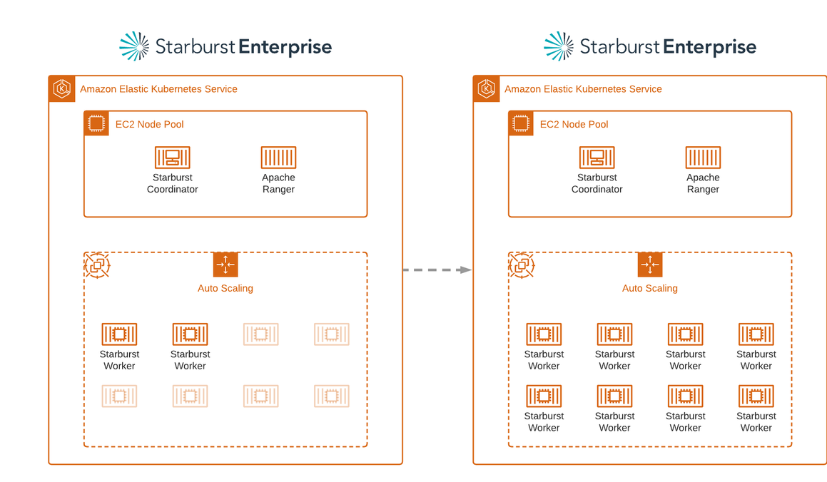


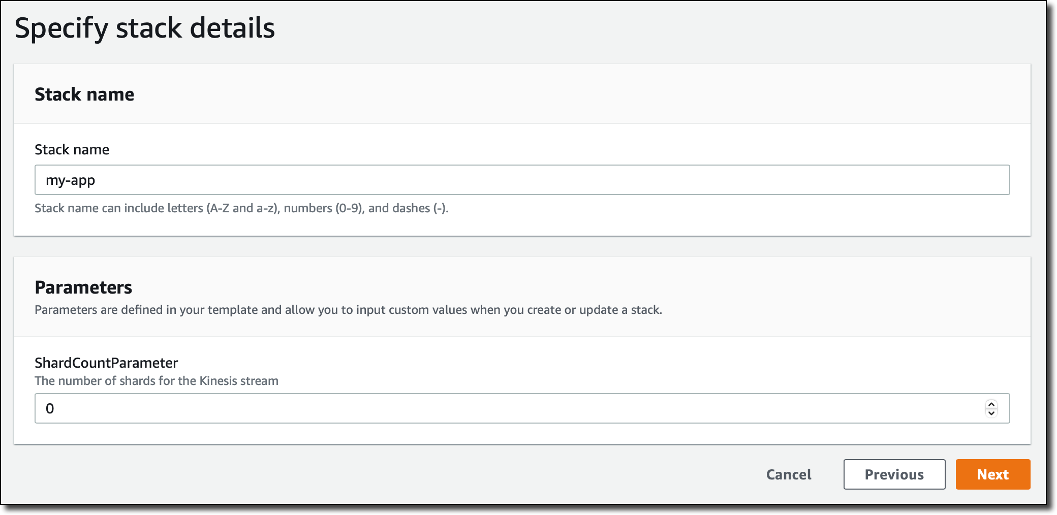


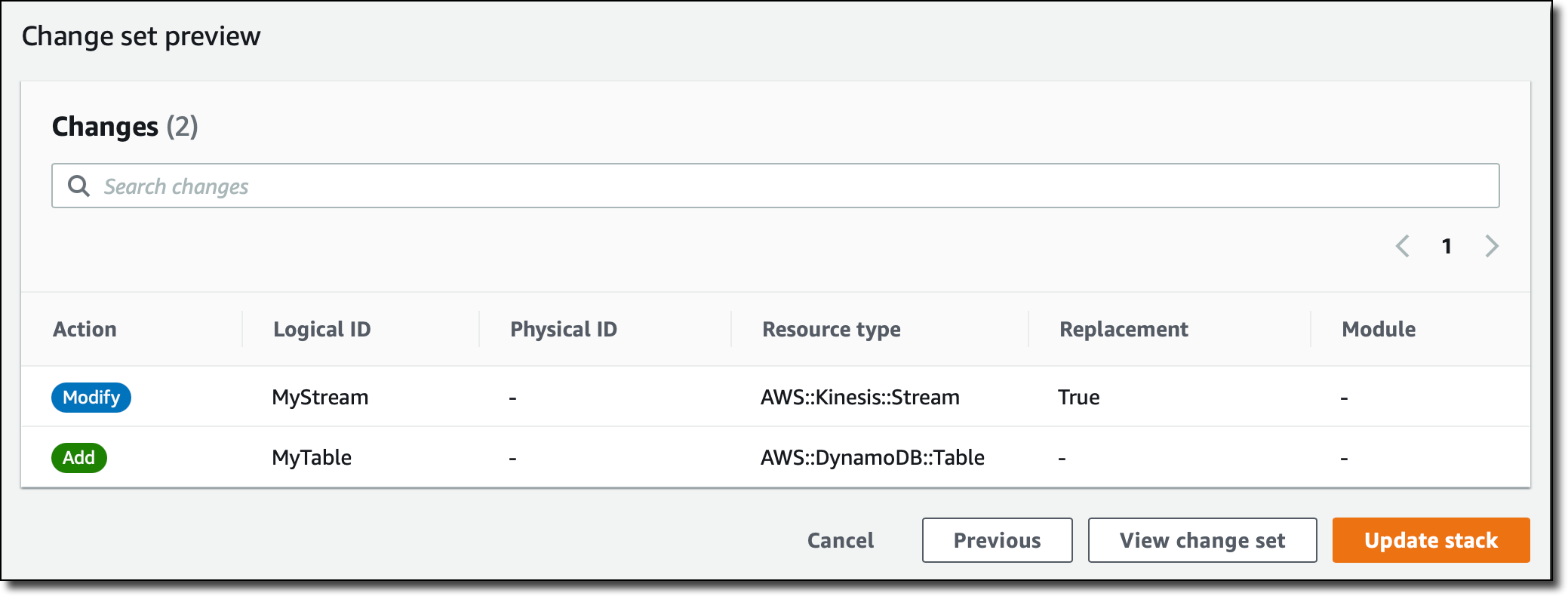





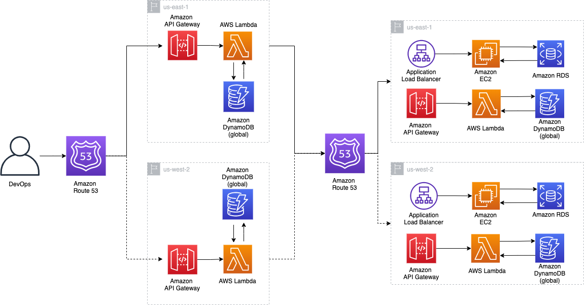
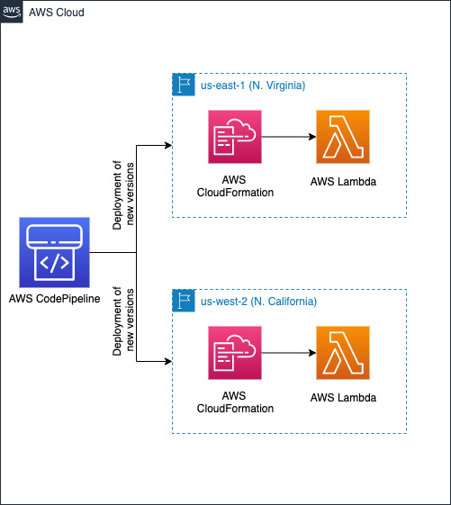

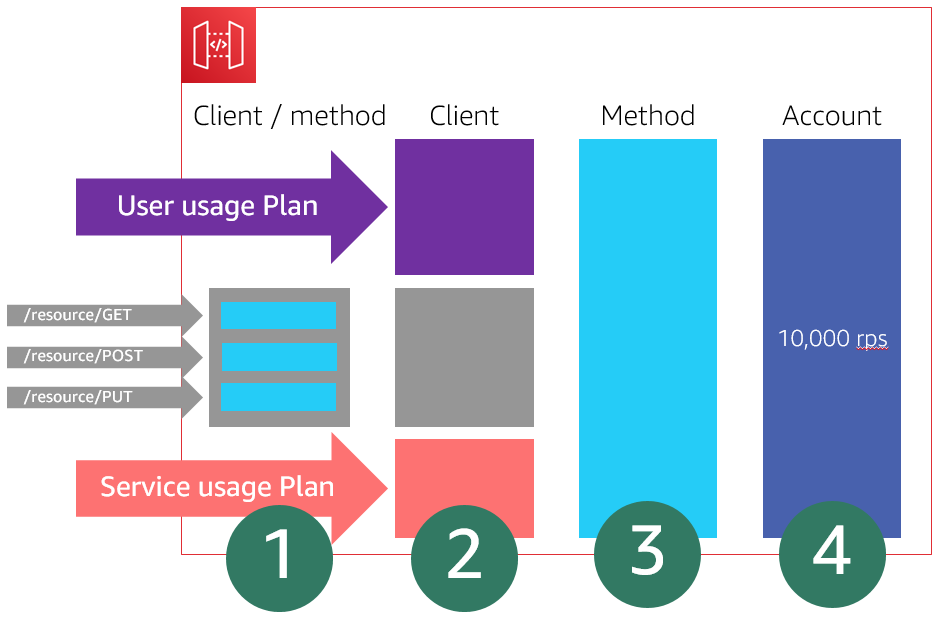

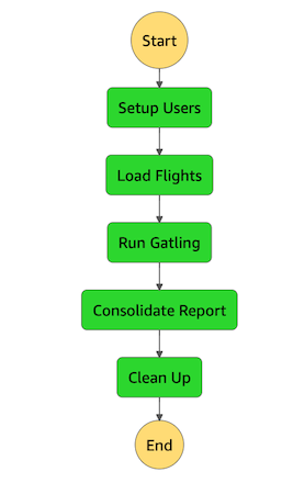
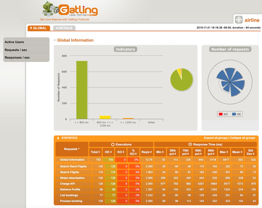


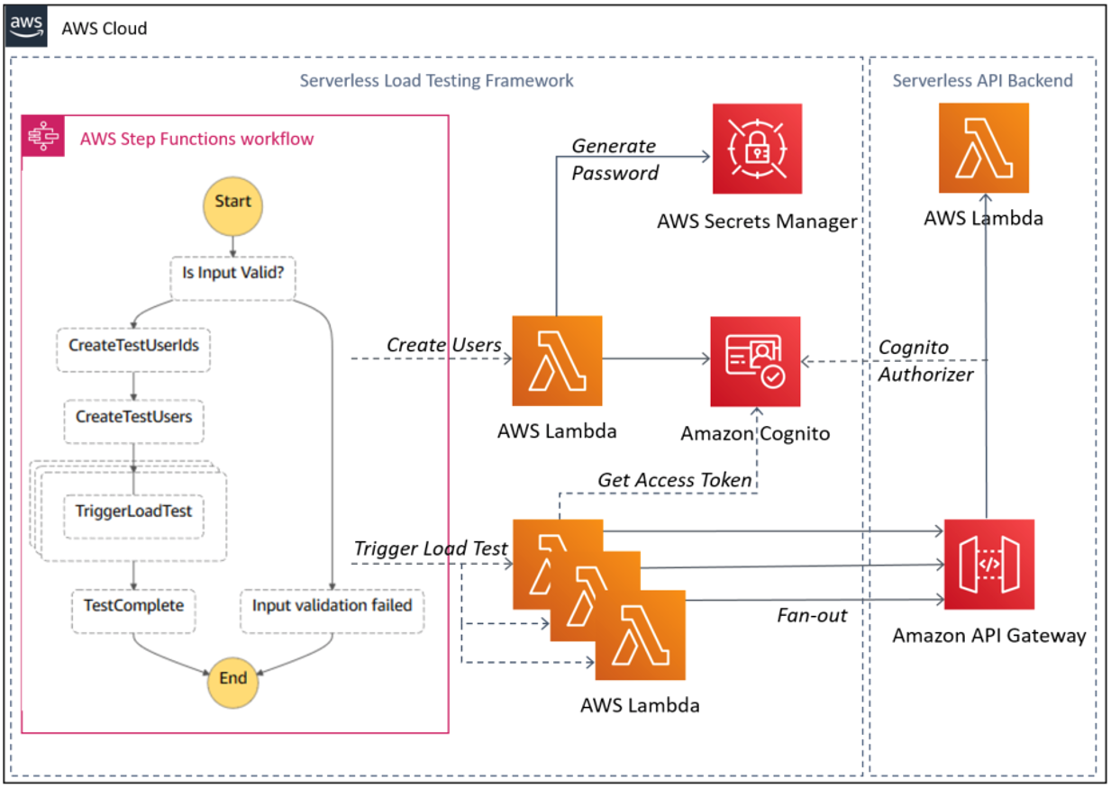


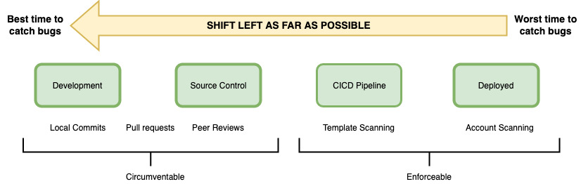
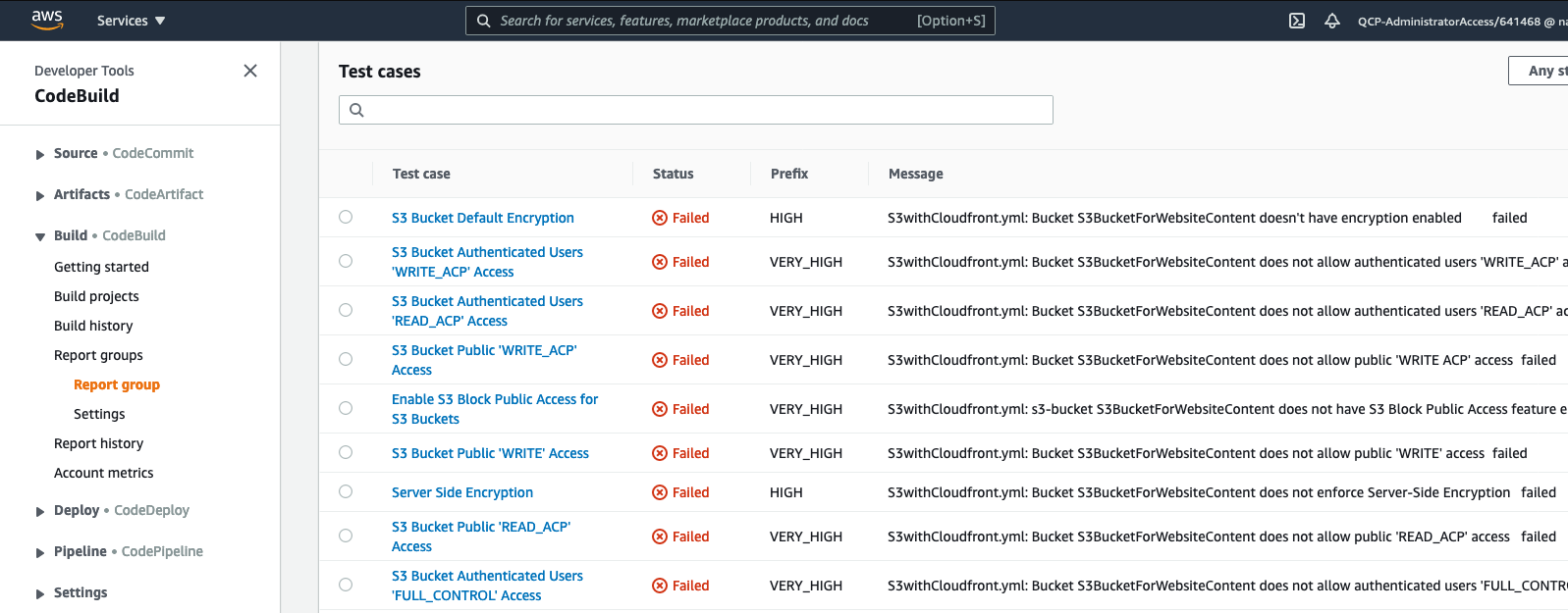
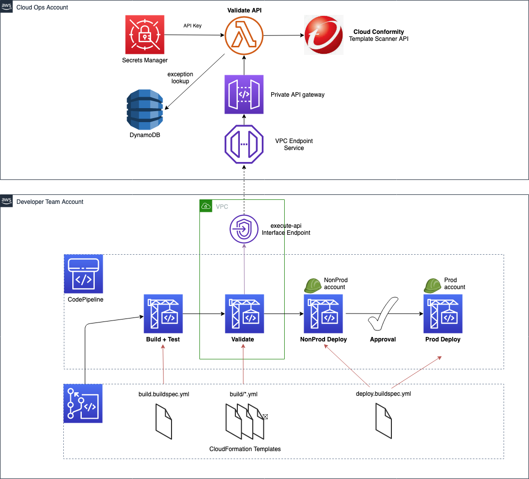
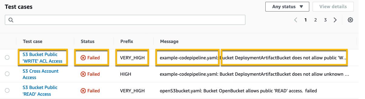
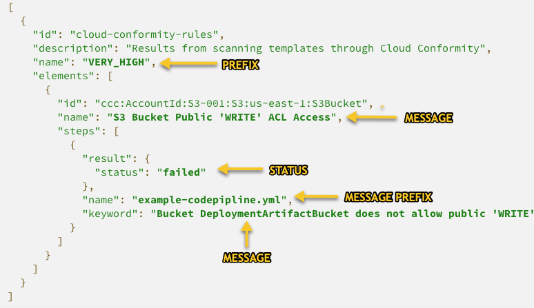
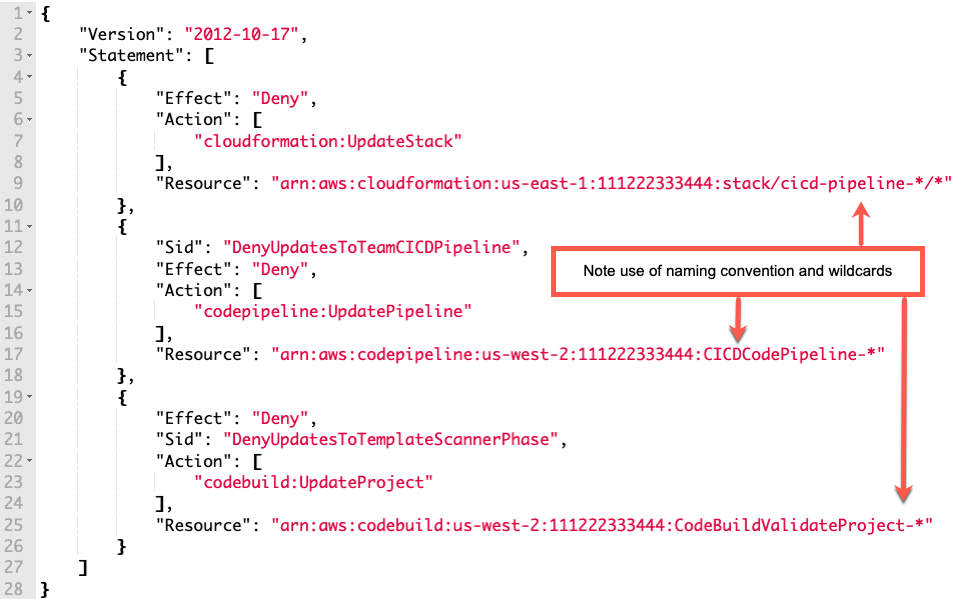
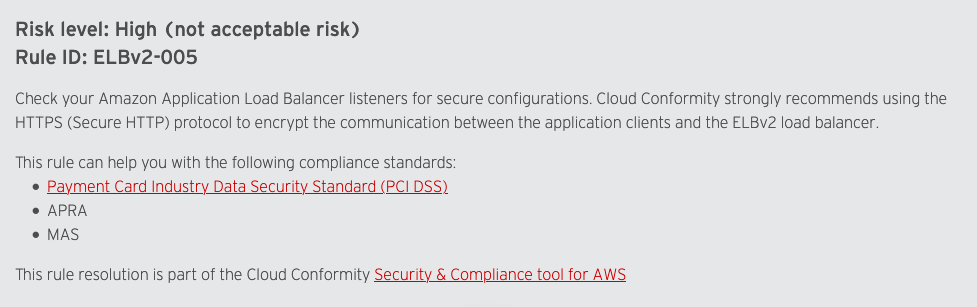
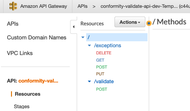
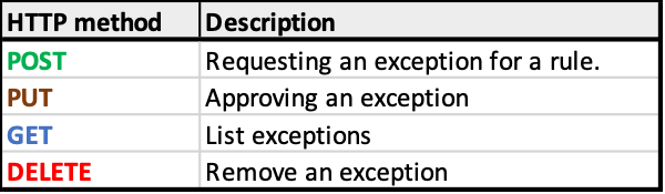
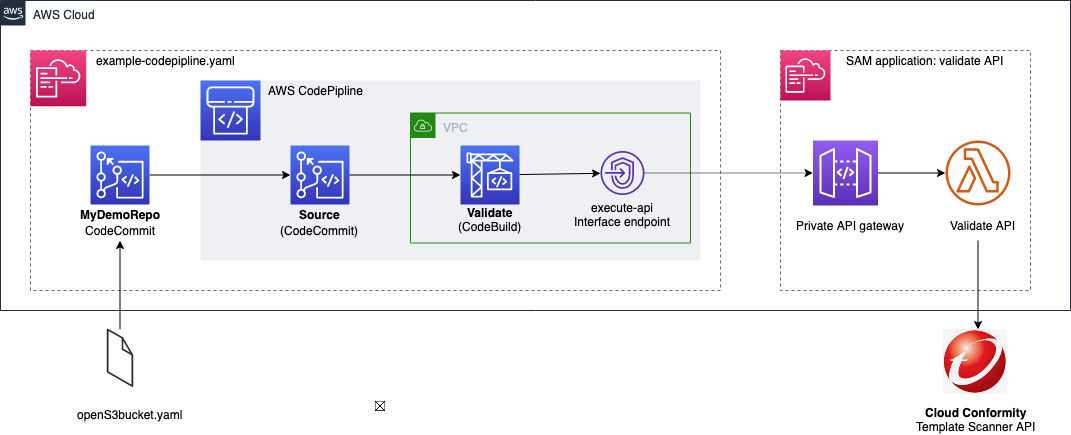






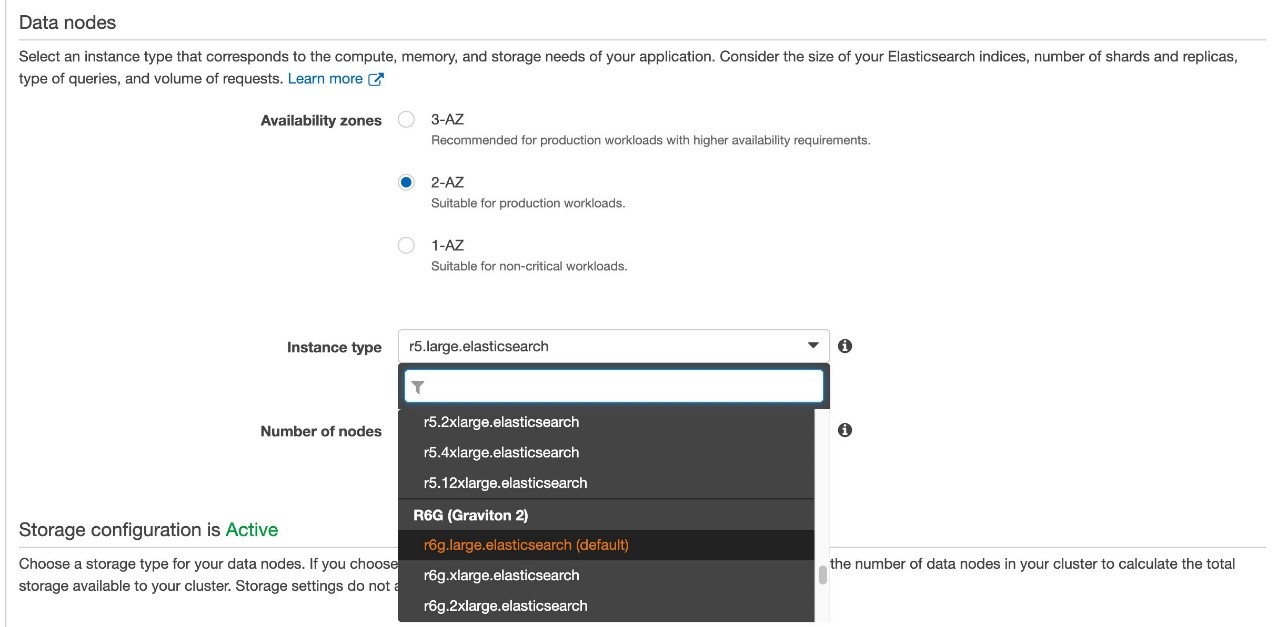



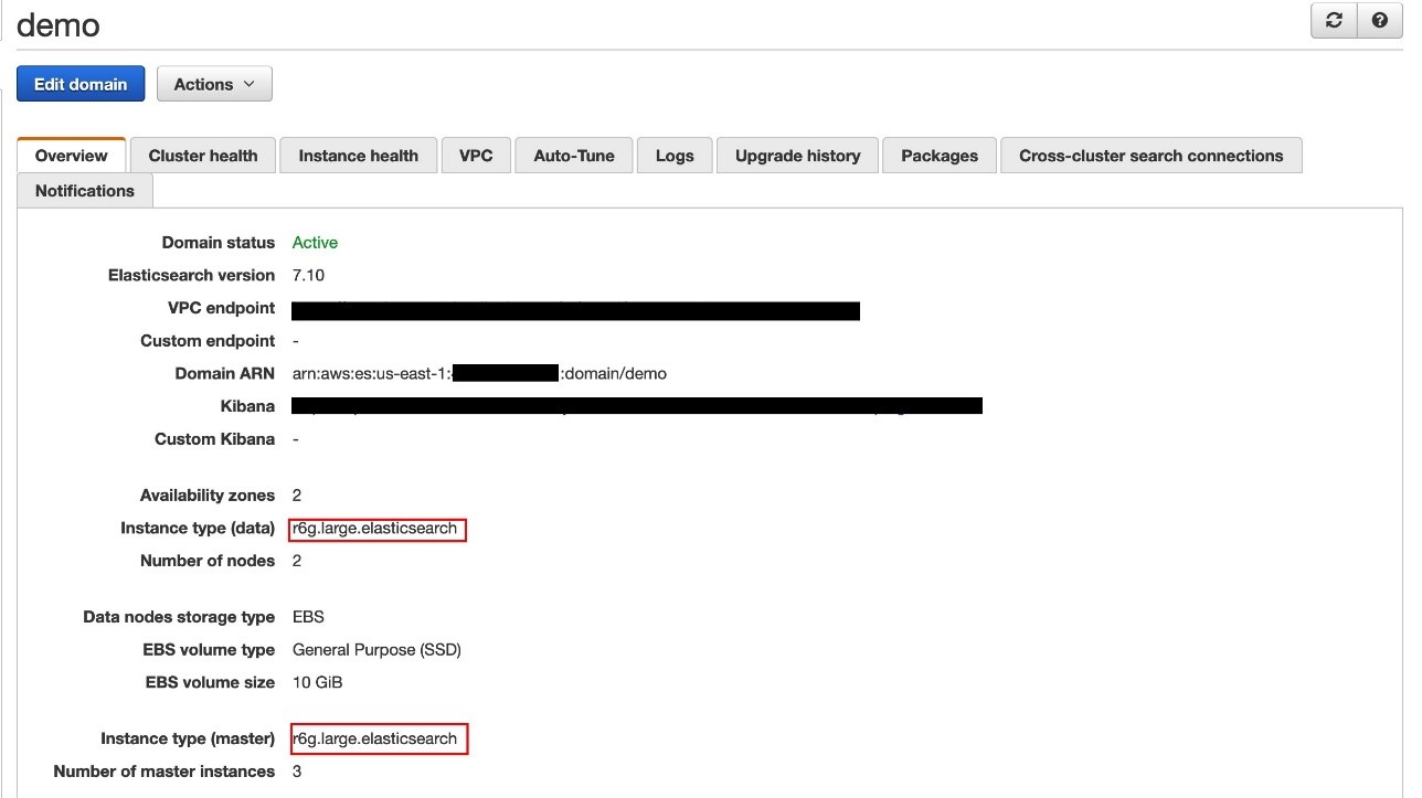
 Zachariah Elliott works as a Solutions Architect focusing on EdTech at AWS. He is passionate about helping customers build Well-Architected solutions on AWS. He is also part of the IoT Subject Matter Expert community at AWS and loves helping customers develop unique IoT-based solutions.
 Pranusha Manchala is a Solutions Architect at AWS who works with education companies. She has worked with many EdTech customers and provided them with architectural guidance for building highly scalable and cost-optimized applications on AWS. She found her interests in machine learning and started to dive deep into this technology. She enjoys cooking, baking, and outdoor activities in her free time.
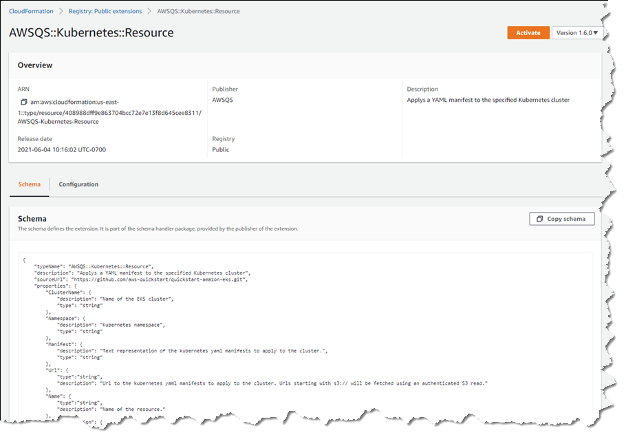


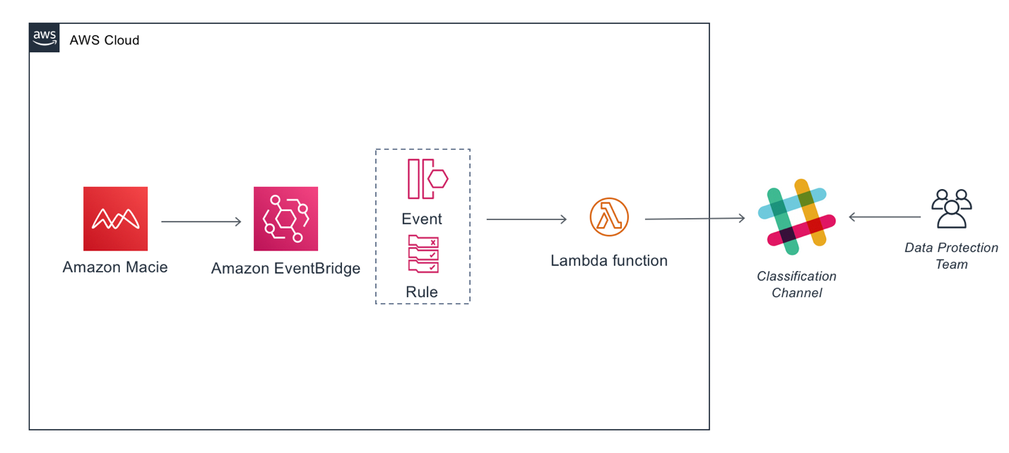


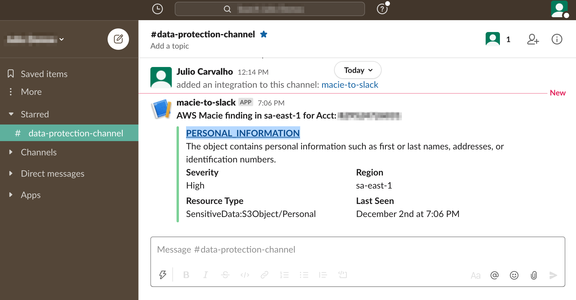
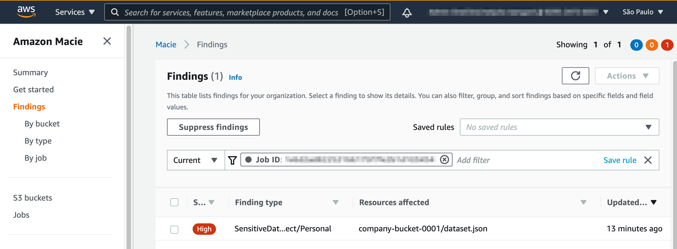
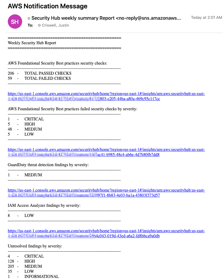
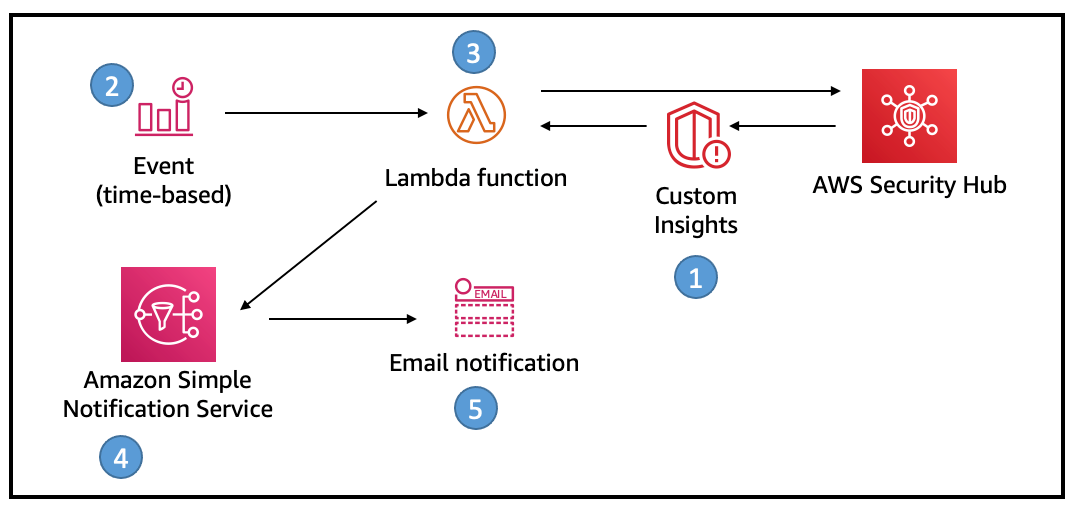
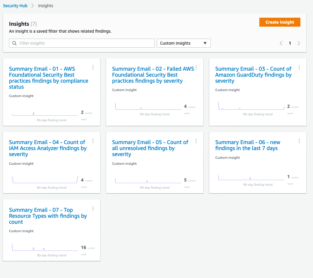
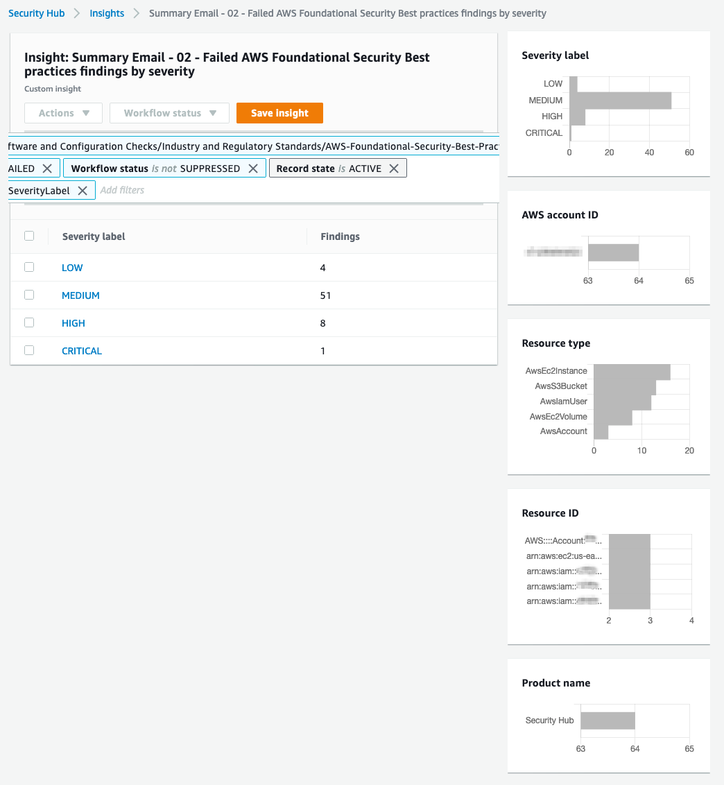


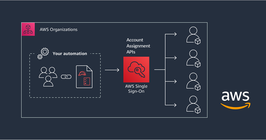
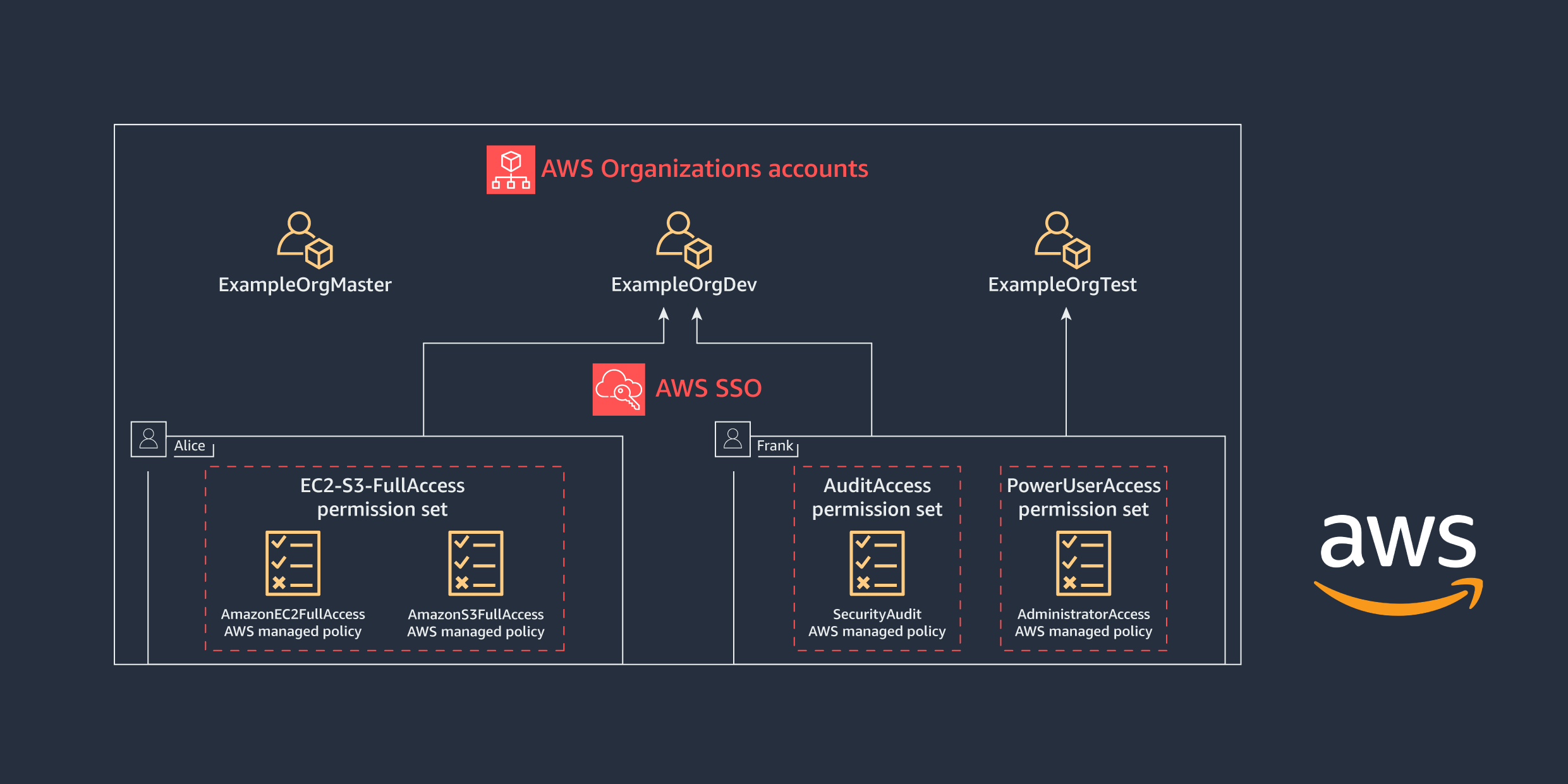
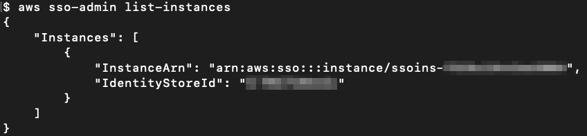









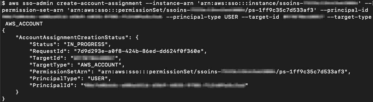
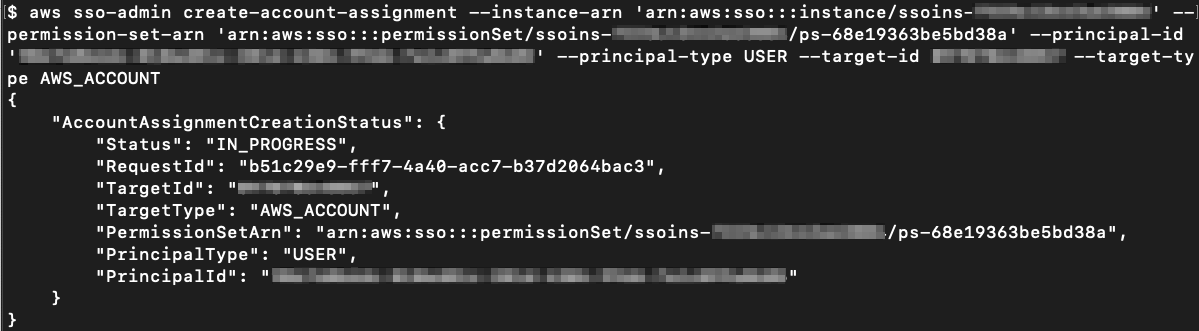
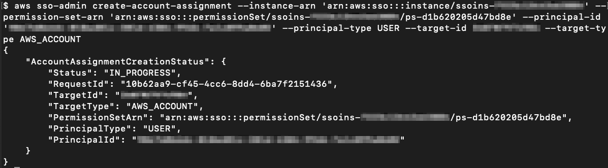

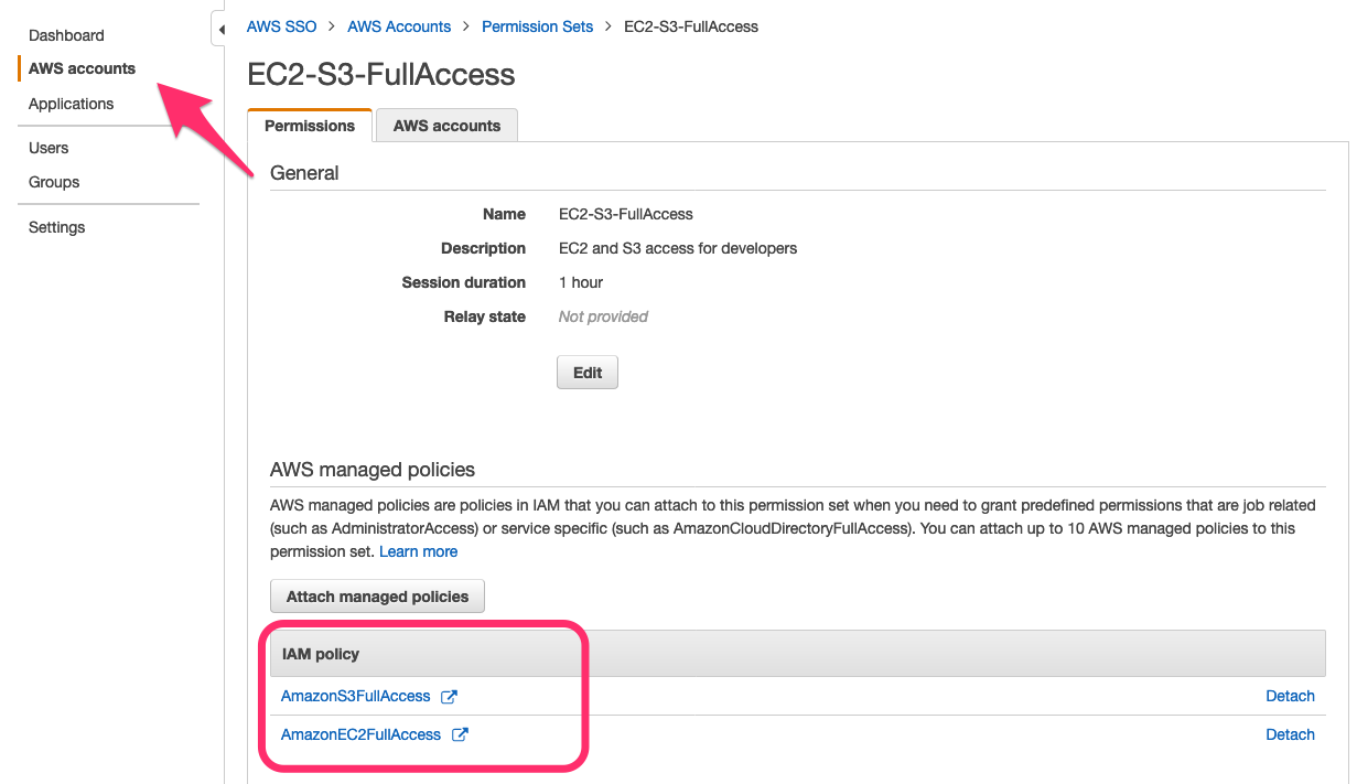
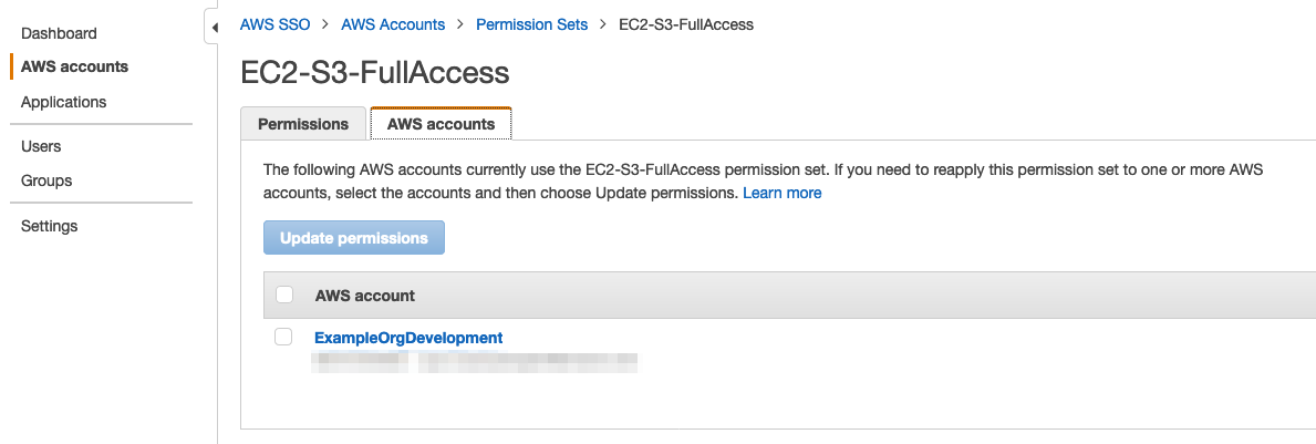
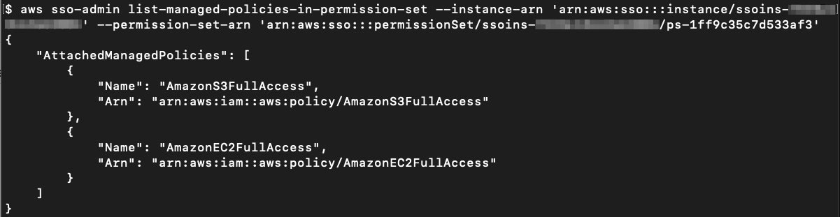
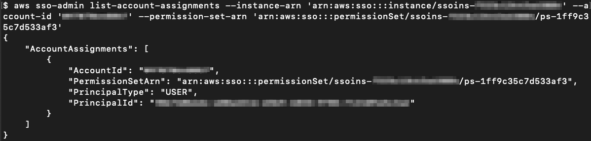

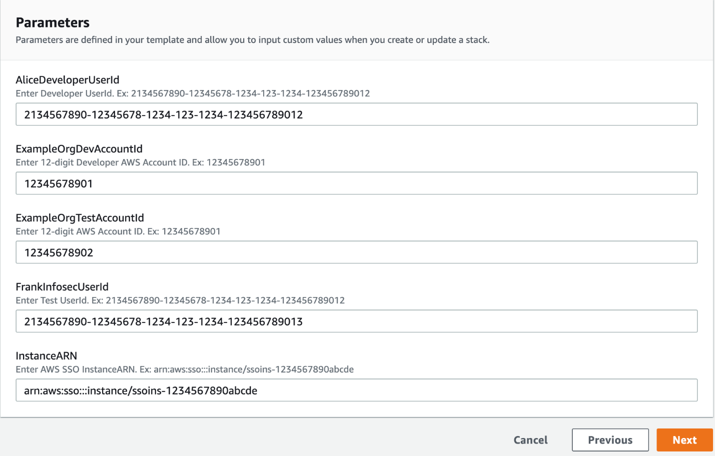
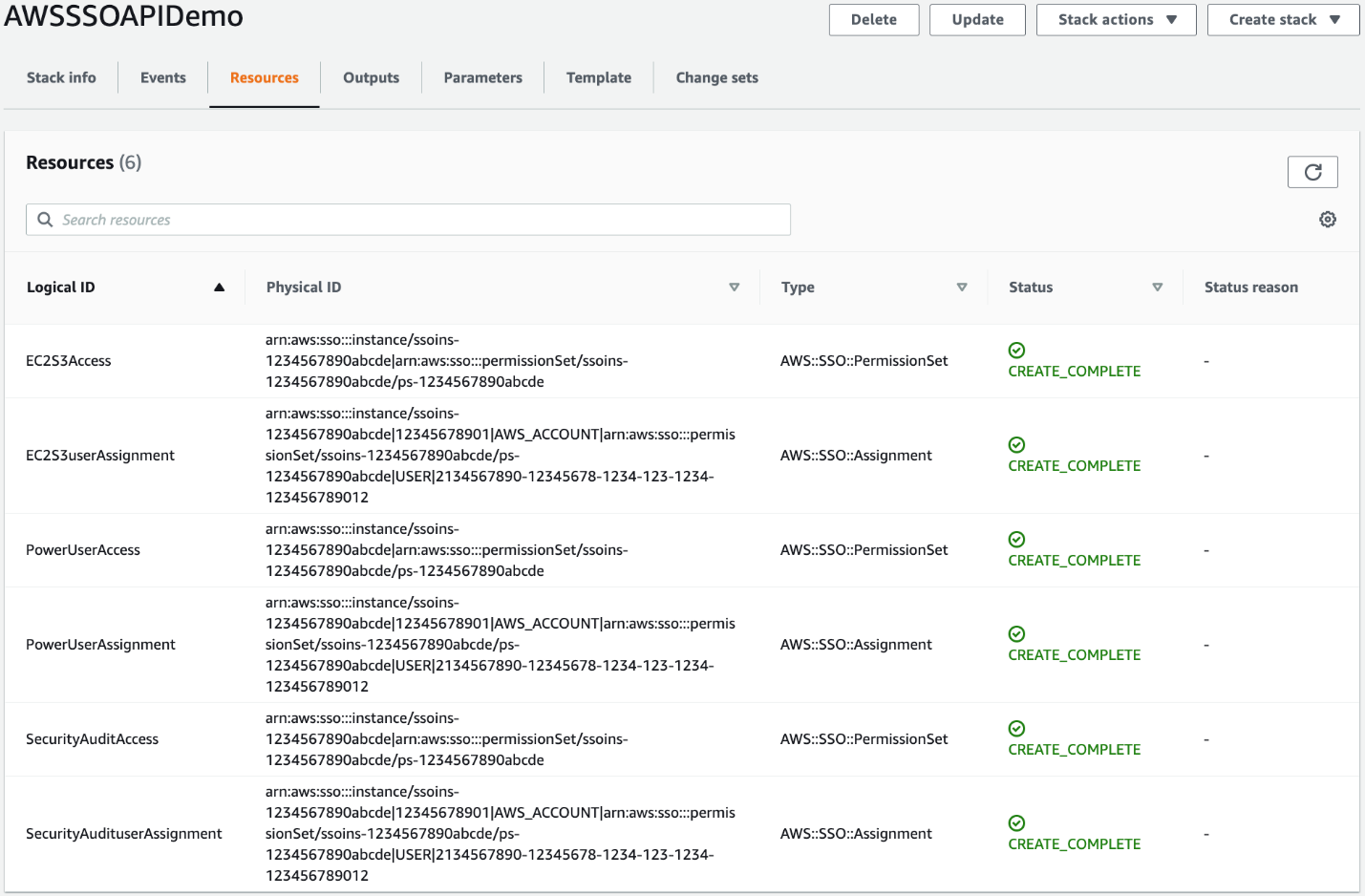



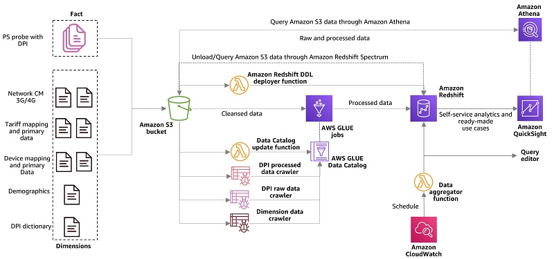


 Vikas Omer is an analytics specialist solutions architect at Amazon Web Services. Vikas has a strong background in analytics, customer experience management (CEM) and data monetization, with over 11 years of experience in the telecommunications industry globally. With six AWS Certifications, including Analytics Specialty, he is a trusted analytics advocate to AWS customers and partners. He loves traveling, meeting customers, and helping them become successful in what they do.