Tag Archives: Developer Tools

New for Amazon CodeGuru Reviewer – Detector Library and Security Detectors for Log-Injection Flaws

Post Syndicated from Danilo Poccia original https://aws.amazon.com/blogs/aws/new-for-amazon-codeguru-reviewer-detector-library-and-security-detectors-for-log-injection-flaws/

Amazon CodeGuru Reviewer is a developer tool that detects security vulnerabilities in your code and provides intelligent recommendations to improve code quality. For example, CodeGuru Reviewer introduced Security Detectors for Java and Python code to identify security risks from the top ten Open Web Application Security Project (OWASP) categories and follow security best practices for AWS APIs and common crypto libraries. At re:Invent, CodeGuru Reviewer introduced a secrets detector to identify hardcoded secrets and suggest remediation steps to secure your secrets with AWS Secrets Manager. These capabilities help you find and remediate security issues before you deploy.

Today, I am happy to share two new features of CodeGuru Reviewer:

  • A new Detector Library describes in detail the detectors that CodeGuru Reviewer uses when looking for possible defects and includes code samples for both Java and Python.
  • New security detectors have been introduced for detecting log-injection flaws in Java and Python code, similar to what happened with the recent Apache Log4j vulnerability we described in this blog post.

Let’s see these new features in more detail.

Using the Detector Library
To help you understand more clearly which detectors CodeGuru Reviewer uses to review your code, we are now sharing a Detector Library where you can find detailed information and code samples.

These detectors help you build secure and efficient applications on AWS. In the Detector Library, you can find detailed information about CodeGuru Reviewer’s security and code quality detectors, including descriptions, their severity and potential impact on your application, and additional information that helps you mitigate risks.

Note that each detector looks for a wide range of code defects. We include one noncompliant and compliant code example for each detector. However, CodeGuru uses machine learning and automated reasoning to identify possible issues. For this reason, each detector can find a range of defects in addition to the explicit code example shown on the detector’s description page.

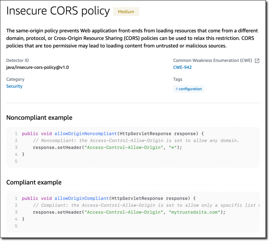
Let’s have a look at a few detectors. One detector is looking for insecure cross-origin resource sharing (CORS) policies that are too permissive and may lead to loading content from untrusted or malicious sources.

Detector Library screenshot.

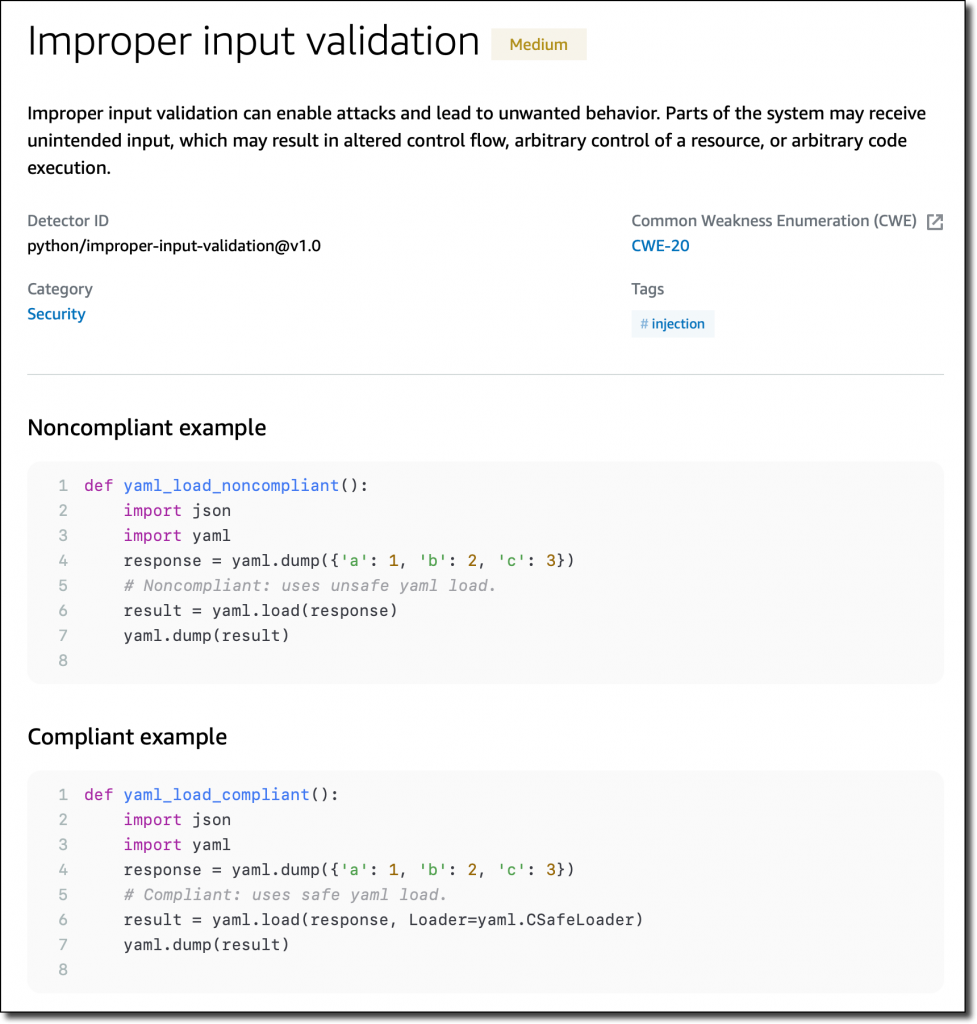
Another detector checks for improper input validation that can enable attacks and lead to unwanted behavior.

Detector Library screenshot.

Specific detectors help you use the AWS SDK for Java and the AWS SDK for Python (Boto3) in your applications. For example, there are detectors that can detect hardcoded credentials, such as passwords and access keys, or inefficient polling of AWS resources.

New Detectors for Log-Injection Flaws
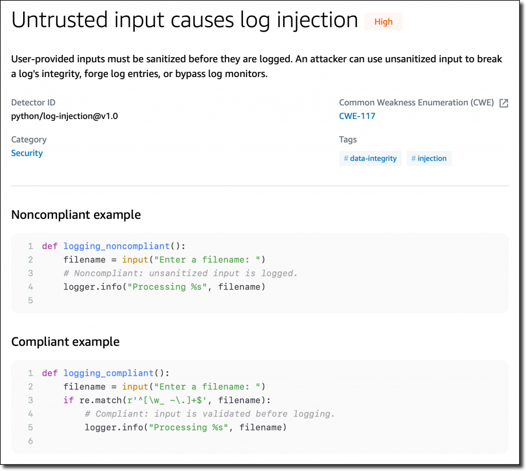
Following the recent Apache Log4j vulnerability, we introduced in CodeGuru Reviewer new detectors that check if you’re logging anything that is not sanitized and possibly executable. These detectors cover the issue described in CWE-117: Improper Output Neutralization for Logs.

These detectors work with Java and Python code and, for Java, are not limited to the Log4j library. They don’t work by looking at the version of the libraries you use, but check what you are actually logging. In this way, they can protect you if similar bugs happen in the future.

Detector Library screenshot.

Following these detectors, user-provided inputs must be sanitized before they are logged. This avoids having an attacker be able to use this input to break the integrity of your logs, forge log entries, or bypass log monitors.

Availability and Pricing
These new features are available today in all AWS Regions where Amazon CodeGuru is offered. For more information, see the AWS Regional Services List.

The Detector Library is free to browse as part of the documentation. For the new detectors looking for log-injection flaws, standard pricing applies. See the CodeGuru pricing page for more information.

Start using Amazon CodeGuru Reviewer today to improve the security of your code.

Danilo

New for App Runner – VPC Support

Post Syndicated from Danilo Poccia original https://aws.amazon.com/blogs/aws/new-for-app-runner-vpc-support/

With AWS App Runner, you can quickly deploy web applications and APIs at any scale. You can start with your source code or a container image, and App Runner will fully manage all infrastructure including servers, networking, and load balancing for your application. If you want, App Runner can also configure a deployment pipeline for you.

Starting today, App Runner enables your services to communicate with databases and other applications hosted in an Amazon Virtual Private Cloud (VPC). For example, you can now connect App Runner services to databases in Amazon Relational Database Service (RDS), Redis or Memcached caches in Amazon ElastiCache, or your own applications running in Amazon Elastic Container Service (Amazon ECS), Amazon Elastic Kubernetes Service (EKS), Amazon Elastic Compute Cloud (Amazon EC2), or on-premises and connected via AWS Direct Connect.

Previously, in order for your App Runner application to connect to these resources, they needed to be publicly accessible over the internet. With this feature, App Runner applications can connect to private endpoints in your VPC, and you can enable a more secure and compliant environment by removing public access to these resources.

Within App Runner, you can now create VPC connectors that specify which VPC, subnets, and security groups to use for private networking. Once configured, you can use a VPC connector with one or more App Runner services.

When connected to a VPC, all outbound traffic from your AppRunner service will be routed based on the VPC routing rules. Services will not have access to the public internet (including AWS APIs) unless allowed by a route to a NAT Gateway. You can also set up VPC endpoints to connect to AWS APIs such as Amazon Simple Storage Service (Amazon S3) and Amazon DynamoDB to avoid NAT traffic.

The VPC connectors in App Runner work similarly to VPC networking in AWS Lambda and are based on AWS Hyperplane, the internal Amazon network function virtualization system behind AWS services and resources like Network Load Balancer, NAT Gateway, and AWS PrivateLink.

Let’s see how this works in practice with a web application connected to an RDS database.

Preparing the Amazon RDS Database
I start by configuring a database for my application. To simplify capacity management for this database, I use Amazon Aurora Serverless. In the RDS console, I create an Amazon Aurora MySQL-Compatible database. For the Capacity type, I choose Serverless. For networking, I use my default VPC and the default security group. I don’t need to make the database publicly accessible because I am going to connect using private VPC networking. To simplify connecting later, I enable AWS Identity and Access Management (IAM) database authentication.

I start an Amazon Linux EC2 instance in the same VPC. To connect from the EC2 instance to the database, I need a MySQL client. I install MariaDB, a community-developed branch of MySQL:

sudo yum install mariadb

Then, I connect to the database using the admin user.

mysql -h <DATABASE_HOST> -u admin -P

I enter the admin user password to log in. Then, I create a new user (bookuser) that is configured to use IAM authentication.

CREATE USER bookuser IDENTIFIED WITH AWSAuthenticationPlugin AS 'RDS'; 

I create the bookcase database and give permissions to the bookuser user to query the bookcase database.

CREATE DATABASE bookcase;
GRANT SELECT ON bookcase.* TO 'bookuser'@'%’;

To store information about some of my books, I create the authors and books tables.

CREATE TABLE authors (
  authorId INT,
  name varchar(255)
 );

CREATE TABLE books (
  bookId INT,
  authorId INT,
  title varchar(255),
  year INT
);

Then, I insert some values in the two tables:

INSERT INTO authors VALUES (1, "Issac Asimov");
INSERT INTO authors VALUES (2, "Robert A. Heinlein");
INSERT INTO books VALUES (1, 1, "Foundation", 1951);
INSERT INTO books VALUES (2, 1, "Foundation and Empire", 1952);
INSERT INTO books VALUES (3, 1, "Second Foundation", 1953);
INSERT INTO books VALUES (4, 2, "Stranger in a Strange Land", 1961);

Preparing the Application Source Code Repository
With App Runner, I can deploy a new service from code hosted in a source code repository or using a container image. In this example, I use a private project that I have on GitHub.

It’s a very simple Python web application connecting to the database I just created. This is the source code of the app (server.py):

from wsgiref.simple_server import make_server
from pyramid.config import Configurator
from pyramid.response import Response
import os
import boto3
import mysql.connector

import os

DATABASE_REGION = 'us-east-1'
DATABASE_CERT = 'cert/us-east-1-bundle.pem'
DATABASE_HOST = os.environ['DATABASE_HOST']
DATABASE_PORT = os.environ['DATABASE_PORT']
DATABASE_USER = os.environ['DATABASE_USER']
DATABASE_NAME = os.environ['DATABASE_NAME']

os.environ['LIBMYSQL_ENABLE_CLEARTEXT_PLUGIN'] = '1'

PORT = int(os.environ.get('PORT'))

rds = boto3.client('rds')

try:
    token = rds.generate_db_auth_token(
        DBHostname=DATABASE_HOST,
        Port=DATABASE_PORT,
        DBUsername=DATABASE_USER,
        Region=DATABASE_REGION
    )
    mydb =  mysql.connector.connect(
        host=DATABASE_HOST,
        user=DATABASE_USER,
        passwd=token,
        port=DATABASE_PORT,
        database=DATABASE_NAME,
        ssl_ca=DATABASE_CERT
    )
except Exception as e:
    print('Database connection failed due to {}'.format(e))          

def all_books(request):
    mycursor = mydb.cursor()
    mycursor.execute('SELECT name, title, year FROM authors, books WHERE authors.authorId = books.authorId ORDER BY year')
    title = 'Books'
    message = '<html><head><title>' + title + '</title></head><body>'
    message += '<h1>' + title + '</h1>'
    message += '<ul>'
    for (name, title, year) in mycursor:
        message += '<li>' + name + ' - ' + title + ' (' + str(year) + ')</li>'
    message += '</ul>'
    message += '</body></html>'
    return Response(message)

if __name__ == '__main__':

    with Configurator() as config:
        config.add_route('all_books', '/')
        config.add_view(all_books, route_name='all_books')
        app = config.make_wsgi_app()
    server = make_server('0.0.0.0', PORT, app)
    server.serve_forever()

The application uses the AWS SDK for Python (boto3) for IAM database authentication, the Pyramid web framework, and the MySQL connector for Python. The requirements.txt file describes the application dependencies:

boto3
pyramid==2.0
mysql-connector-python

To use SSL/TLS encryption when connecting to the database, I download a certificate bundle and add it to my source code repository.

Using VPC Support in AWS App Runner
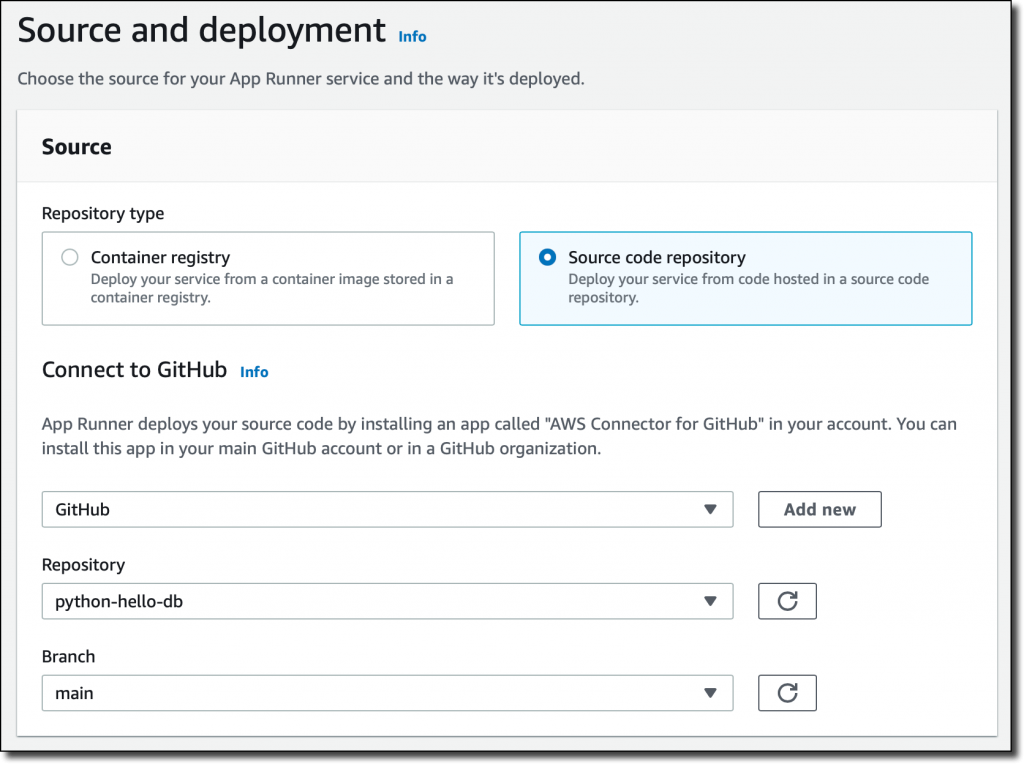
In the App Runner console, I select Source code repository and the branch to use.

Console screenshot.

For the deployment settings, I choose Manual. Optionally, I could have selected the Automatic deployment trigger to have every push to this branch deploy a new version of my service.

Console screenshot.

Then, I configure the build. This is a very simple application, so I pass the build and start commands in the console:

Build commandpip install -r requirements.txt
Start commandpython server.py

For more advanced use cases, I would add an apprunner.yaml configuration file to my repository as in this sample application.

Console screenshot.

In the service configuration, I add the environment variables used by the application to connect to the database. I don’t need to pass a database password here because I am using IAM authentication.

Console screenshot.

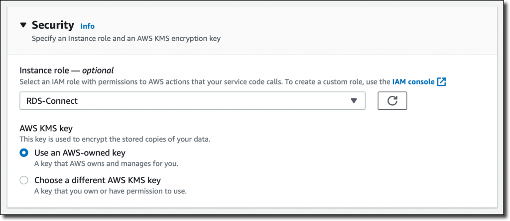
In the Security section, I select an IAM role that gives permissions to connect to the database using IAM database authentication as described in Creating and using an IAM policy for IAM database access.

Console screenshot.

Here’s the syntax of the IAM role. I find the database Resource ID in the Configuration tab of the RDS console.

{
    "Version": "2012-10-17",
    "Statement": [
        {
            "Effect": "Allow",
            "Action": [
                "rds-db:connect"
            ],
            "Resource": [
                "arn:aws:rds-db:<REGION>:<ACCOUNT>:dbuser:<DB_RESOURCE_ID>/<DB_USER>"
            ]
        }
    ]
}

For the role trust policy,   I follow the instruction for instance roles in How App Runner works with IAM.

{
  "Version": "2012-10-17",
  "Statement": [
    {
      "Effect": "Allow",
      "Principal": {
        "Service": "tasks.apprunner.amazonaws.com"
      },
      "Action": "sts:AssumeRole"
    }
  ]
}

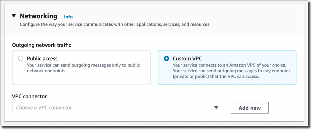
For Networking, I select the new option to use a Custom VPC for outgoing network traffic and then add a new VPC connector.

Console screenshot.

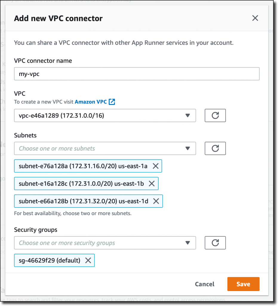
To add a new VPC connector, I write down a name and then select the VPC, subnets, and security groups to use. Here, I select all the subnets of my default VPC and the default security group. In this way, the App Runner service will be able to connect to the RDS database.

Console screenshot.

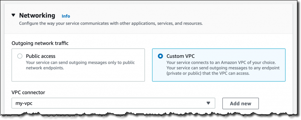
The next time, when configuring another application with the same VPC networking requirements, I can just select the VPC connector I created before.

Console screenshot. I review all the settings and then create and deploy the service.

After a few minutes, the service is running, and I choose the default domain to open a new tab in my browser. The application is connected to the database using VPC networking and performs a SQL query to join the books and authors tables and provide some reading suggestions. It works!

Browser screenshot.

Availability and Pricing
VPC connectors are available in all AWS Regions where AWS App Runner is offered. For more information, see the Regional Services List. There is no additional cost for using this feature, but you pay the standard pricing for data transmission or any NAT gateway or VPC endpoints you set up. You can set up VPC connectors with the AWS Management Console, AWS Command Line Interface (CLI), AWS SDKs, and AWS CloudFormation.

With VPC connectors, you can deploy your applications using App Runner and connect them to your private databases, caches, and applications running in a VPC or on-premises and connected via AWS Direct Connect.

Build and run web applications at any scale and connect to your private VPC resources with AWS App Runner.

Danilo

Using Amazon Aurora Global Database for Low Latency without Application Changes

Post Syndicated from Roneel Kumar original https://aws.amazon.com/blogs/architecture/using-amazon-aurora-global-database-for-low-latency-without-application-changes/

Deploying global applications has many challenges, especially when accessing a database to build custom pages for end users. One example is an application using AWS Lambda@Edge. Two main challenges include performance and availability.

This blog explains how you can optimally deploy a global application with fast response times and without application changes.

The Amazon Aurora Global Database enables a single database cluster to span multiple AWS Regions by asynchronously replicating your data within subsecond timing. This provides fast, low-latency local reads in each Region. It also enables disaster recovery from Region-wide outages using multi-Region writer failover. These capabilities minimize the recovery time objective (RTO) of cluster failure, thus reducing data loss during failure. You will then be able to achieve your recovery point objective (RPO).

However, there are some implementation challenges. Most applications are designed to connect to a single hostname with atomic, consistent, isolated, and durable (ACID) consistency. But Global Aurora clusters provide reader hostname endpoints in each Region. In the primary Region, there are two endpoints, one for writes, and one for reads. To achieve strong  data consistency, a global application requires the ability to:

  • Choose the optimal reader endpoints
  • Change writer endpoints on a database failover
  • Intelligently select the reader with the most up-to-date, freshest data

These capabilities typically require additional development.

The Heimdall Proxy coupled with Amazon Route 53 allows edge-based applications to access the Aurora Global Database seamlessly, without  application changes. Features include automated Read/Write split with ACID compliance and edge results caching.

Figure 1. Heimdall Proxy architecture

Figure 1. Heimdall Proxy architecture

The architecture in Figure 1 shows Aurora Global Databases primary Region in AP-SOUTHEAST-2, and secondary Regions in AP-SOUTH-1 and US-WEST-2. The Heimdall Proxy uses latency-based routing to determine the closest Reader Instance for read traffic, and redirects all write traffic to the Writer Instance. The Heimdall Configuration stores the Amazon Resource Name (ARN) of the global cluster. It automatically detects failover and cross-Region on the cluster, and directs traffic accordingly.

With an Aurora Global Database, there are two approaches to failover:

  • Managed planned failover. To relocate your primary database cluster to one of the secondary Regions in your Aurora global database, see Managed planned failovers with Amazon Aurora Global Database. With this feature, RPO is 0 (no data loss) and it synchronizes secondary DB clusters with the primary before making any other changes. RTO for this automated process is typically less than that of the manual failover.
  • Manual unplanned failover. To recover from an unplanned outage, you can manually perform a cross-Region failover to one of the secondaries in your Aurora Global Database. The RTO for this manual process depends on how quickly you can manually recover an Aurora global database from an unplanned outage. The RPO is typically measured in seconds, but this is dependent on the Aurora storage replication lag across the network at the time of the failure.

The Heimdall Proxy automatically detects Amazon Relational Database Service (RDS) / Amazon Aurora configuration changes based on the ARN of the Aurora Global cluster. Therefore, both managed planned and manual unplanned failovers are supported.

Solution benefits for global applications

Implementing the Heimdall Proxy has many benefits for global applications:

  1. An Aurora Global Database has a primary DB cluster in one Region and up to five secondary DB clusters in different Regions. But the Heimdall Proxy deployment does not have this limitation. This allows for a larger number of endpoints to be globally deployed. Combined with Amazon Route 53 latency-based routing, new connections have a shorter establishment time. They can use connection pooling to connect to the database, which reduces overall connection latency.
  2. SQL results are cached to the application for faster response times.
  3. The proxy intelligently routes non-cached queries. When safe to do so, the closest (lowest latency) reader will be used. When not safe to access the reader, the query will be routed to the global writer. Proxy nodes globally synchronize their state to ensure that volatile tables are locked to provide ACID compliance.

For more information on configuring the Heimdall Proxy and Amazon Route 53 for a global database, read the Heimdall Proxy for Aurora Global Database Solution Guide.

Download a free trial from the AWS Marketplace.

Resources:

Heimdall Data, based in the San Francisco Bay Area, is an AWS Advanced ISV partner. They have AWS Service Ready designations for Amazon RDS and Amazon Redshift. Heimdall Data offers a database proxy that offloads SQL improving database scale. Deployment does not require code changes.

New – Amazon CloudWatch Evidently – Experiments and Feature Management

Post Syndicated from Sébastien Stormacq original https://aws.amazon.com/blogs/aws/cloudwatch-evidently/

As a developer, I am excited to announce the availability of Amazon CloudWatch Evidently. This is a new Amazon CloudWatch capability that makes it easy for developers to introduce experiments and feature management in their application code. CloudWatch Evidently may be used for two similar but distinct use-cases: implementing dark launches, also known as feature flags, and A/B testing.

Features flags is a software development technique that lets you enable or disable features without needing to deploy your code. It decouples the feature deployment from the release. Features in your code are deployed in advance of the actual release. They stay hidden behind if-then-else statements. At runtime, your application code queries a remote service. The service decides the percentage of users who are exposed to the new feature. You can also configure the application behavior for some specific customers, your beta testers for example.

When you use feature flags you can deploy new code in advance of your launch. Then, you can progressively introduce a new feature to a fraction of your customers. During the launch, you monitor your technical and business metrics. As long as all goes well, you may increase traffic to expose the new feature to additional users. In the case that something goes wrong, you may modify the server-side routing with just one click or API call to present only the old (and working) experience to your customers. This lets you revert back user experience without requiring rollback deployments.

A/B Testing shares many similarities with feature flags while still serving a different purpose. A/B tests consist of a randomized experiment with multiple variations. A/B testing lets you compare multiple versions of a single feature, typically by testing the response of a subject to variation A against variation B, and determining which of the two is more effective. For example, let’s imagine an e-commerce website (a scenario we know quite well at Amazon). You might want to experiment with different shapes, sizes, or colors for the checkout button, and then measure which variation has the most impact on revenue.

The infrastructure required to conduct A/B testing is similar to the one required by feature flags. You deploy multiple scenarios in your app, and you control how to route part of the customer traffic to one scenario or the other. Then, you perform deep dive statistical analysis to compare the impacts of variations. CloudWatch Evidently assists in interpreting and acting on experimental results without the need for advanced statistical knowledge. You can use the insights provided by Evidently’s statistical engine, such as anytime p-value and confidence intervals for decision-making while an experiment is in progress.

At Amazon, we use feature flags extensively to control our launches, and A/B testing to experiment with new ideas. We’ve acquired years of experience to build developers’ tools and libraries and maintain and operate experimentation services at scale. Now you can benefit from our experience.

CloudWatch Evidently uses the terms “launches” for feature flags and “experiments” for A/B testing, and so do I in the rest of this article.

Let’s see how it works from an application developer point of view.

Launches in Action
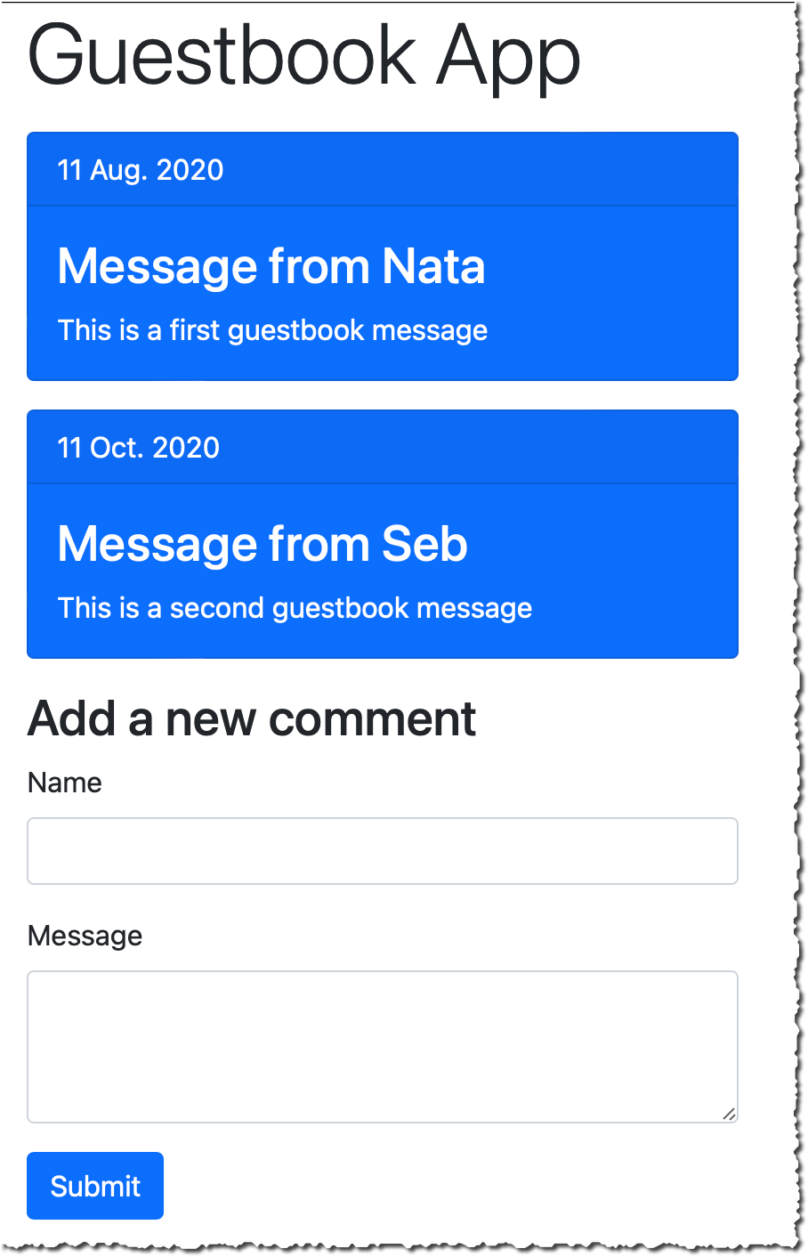
For this demo, I use a simple Guestbook web application. So far, the guest book page is read-only, and comments are entered from our back-end only. I developed a new feature to let customers enter their comments on the guestbook page. I want to launch this new feature progressively over a week and keep the ability to revert the change back if it impacts important technical or business metrics (such as p95 latency, customer engagement, page views, etc.). Users are authenticated, and I will segment users based on their user ID.

Before launch:
Evidently - experiment off
After launch:
Evidently - experiment on

Create a Project
Let’s start by configuring Evidently. I open the AWS Management Console and navigate to CloudWatch Evidently. Then, I select Create a project.

Evidently - create project


I enter a Project name and Description.

Evidently lets you optionally store events to CloudWatch logs or S3, so that you can move them to systems such as Amazon Redshift to perform analytical operations. For this demo, I choose not to store events. When done, I select Create project.

Evidently - create project second part

Add a Feature
Next, I create a feature for this project by selecting Add feature. I enter a Feature name and Feature description. Next, I define my Feature variations. In this example, there are two variations, and I use a Boolean type. true indicates the guestbook is editable and false indicates it is read only. Variations types might be boolean, double, long, or string.

Evidently - create featureI may define overrides. Overrides let me pre-define the variation for selected users. I want the user “seb”, my beta tester, to always receive the editable variation.

Evidently - Create feature - overridesThe console shares the JavaScript and Java code snippets to add into my application.

Evidently - code snippetTalking about code snippets, let’s look at the changes at the code level.

Instrument my Application Code
I use a simple web application for this demo. I coded this application using JavaScript. I use the AWS SDK for JavaScript and Webpack to package my code. I also use JQuery to manipulate the DOM to hide or show elements. I designed this application to use standard JavaScript and a minimum number of frameworks to make this example inclusive to all. Feel free to use higher level tools and frameworks, such as React or Angular for real-life projects.

I first initialize the Evidently client. Just like other AWS Services, I have to provide an access key and secret access key for authentication. Let’s leave the authentication part out for the moment. I added a note at the end of this article to discuss the options that you have. In this example, I use Amazon Cognito Identity Pools to receive temporary credentials.

// Initialize the Amazon CloudWatch Evidently client
const evidently = new AWS.Evidently({
    endpoint: EVIDENTLY_ENDPOINT,
    region: 'us-east-1',
    credentials: fromCognitoIdentityPool({
        client: new CognitoIdentityClient({ region: 'us-west-2' }),
        identityPoolId: IDENTITY_POOL_ID
    }),
});

Armed with this client, my code may invoke the EvaluateFeature API to make decisions about the variation to display to customers. The entityId is any string-based attribute to segment my customers. It might be a session ID, a customer ID, or even better, a hash of these. The featureName parameter contains the name of the feature to evaluate. In this example, I pass the value EditableGuestBook.

const evaluateFeature = async (entityId, featureName) => {

    // API request structure
    const evaluateFeatureRequest = {
        // entityId for calling evaluate feature API
        entityId: entityId,
        // Name of my feature
        feature: featureName,
        // Name of my project
        project: "AWSNewsBlog",
    };

    // Evaluate feature
    const response = await evidently.evaluateFeature(evaluateFeatureRequest).promise();
    console.log(response);
    return response;
}

The response contains the assignment decision from Evidently, as based on traffic rules defined on the server-side.

{
 details: {
   launch: "EditableGuestBook", group: "V2"},
   reason: "LAUNCH_RULE_MATCH", 
   value: {boolValue: false},
   variation: "readonly"
}}

The last part consists of hiding or displaying part of the user interface based on the value received above. Using basic JQuery DOM manipulation, it would be something like the following:

window.aws.evaluateFeature(entityId, 'EditableGuestbook').then((response, error) => {
    if (response.value.boolValue) {
        console.log('Feature Flag is on, showing guest book');
        $('div#guestbook-add').show();
    } else {
        console.log('Feature Flag is off, hiding guest book');
        $('div#guestbook-add').hide();
    }
});

Create a Launch
Now that the feature is defined on the server-side, and the client code is instrumented, I deploy the code and expose it to my customers. At a later stage, I may decide to launch the feature. I navigate back to the console, select my project, and select Create Launch. I choose a Launch name and a Launch description for my launch. Then, I select the feature I want to launch.

Evidently - create launchIn the Launch Configuration section, I configure how much traffic is sent to each variation. I may also schedule the launch with multiple steps. This lets me plan different steps of routing based on a schedule. For example, on the first day, I may choose to send 10% of the traffic to the new feature, and on the second day 20%, etc. In this example, I decide to split the traffic 50/50.

Evidently - launch configurationFinally, I may define up to three metrics to measure the performance of my variations. Metrics are defined by applying rules to data events.

Evidently - Custom MetricsAgain, I have to instrument my code to send these metrics with PutProjectEvents API from Evidently. Once my launch is created, the EvaluateFeature API returns different values for different values of entityId (users in this demo).

At any moment, I may change the routing configuration. Moreover, I also have access to a monitoring dashboard to observe the distribution of my variations and the metrics for each variation.

Evidently - launch monitoringI am confident that your real-life launch graph will get more data than mine did, as I just created it to write this post.

A/B Testing
Doing an A/B test is similar. I create a feature to test, and I create an Experiment. I configure the experiment to route part of the traffic to variation 1, and then the other part to variation 2. When I am ready to launch the experiment, I explicitly select Start experiment.

Evidently - start experiment

In this experiment, I am interested in sending custom metrics. For example:

// pageLoadTime custom metric
const timeSpendOnHomePageData = `{
   "details": {
      "timeSpendOnHomePage": ${timeSpendOnHomePageValue}
   },
   "userDetails": { "userId": "${randomizedID}", "sessionId": "${randomizedID}" }
}`;

const putProjectEventsRequest: PutProjectEventsRequest = {
   project: 'AWSNewsBlog',
   events: [
    {
        timestamp: new Date(),
        type: 'aws.evidently.custom',
        data: JSON.parse(timeSpendOnHomePageData)
    },
   ],
};

this.evidently.putProjectEvents(putProjectEventsRequest).promise().then(res =>{})

Switching to the Results page, I see raw values and graph data for Event Count, Total Value, Average, Improvement (with 95% confidence interval), and Statistical significance. The statistical significance describes how certain we are that the variation has an effect on the metric as compared to the baseline.

These results are generated throughout the experiment and the confidence intervals and the statistical significance are guaranteed to be valid anytime you want to view them. Additionally, at the end of the experiment, Evidently also generates a Bayesian perspective of the experiment that provides information about how likely it is that a difference between the variations exists.

The following two screenshots show graphs for the average value of two metrics over time, and the improvement for a metric within a 95% confidence interval.

Evidently - experiment monitoring - average valuesEvidently - experiment monitoring - improvement

Additional Thoughts
Before we wrap-up, I’d like to share some additional considerations.

First, it is important to understand that I choose to demo Evidently in the context of front-end application development. However, you may use Evidently with any application type: front-end web or mobile, back-end API, or even machine learning (ML). For example, you may use Evidently to deploy two different ML models and conduct experiments just like I showed above.

Second, just like with other AWS Services, Evidently API is available in all of our AWS SDK. This lets you use EvaluateFeature and other APIs from nine programing languages: C++, Go, Java, JavaScript (and Typescript), .Net, NodeJS, PHP, Python, and Ruby. AWS SDK for Rust and Swift are in the making.

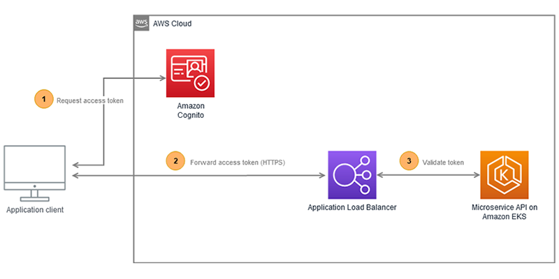
Third, for a front-end application as I demoed here, it is important to consider how to authenticate calls to Evidently API. Hard coding access keys and secret access keys is not an option. For the front-end scenario, I suggest that you use Amazon Cognito Identity Pools to exchange user identity tokens for a temporary access and secret keys. User identity tokens may be obtained from Cognito User Pools, or third-party authentications systems, such as Active Directory, Login with Amazon, Login with Facebook, Login with Google, Signin with Apple, or any system compliant with OpenID Connect or SAML. Cognito Identity Pools also allows for anonymous access. No identity token is required. Cognito Identity Pools vends temporary tokens associated with IAM roles. You must Allow calls to the evidently:EvaluateFeature API in your policies.

Finally, when using feature flags, plan for code cleanup time during your sprints. Once a feature is launched, you might consider removing calls to EvaluateFeature API and the if-then-else logic used to initially hide the feature.

Pricing and Availability
Amazon Cloudwatch Evidently is generally available in nine AWS Regions: US East (N. Virginia), US East (Ohio), US West (Oregon), Asia Pacific (Singapore), Asia Pacific (Sydney), Asia Pacific (Tokyo), Europe (Ireland), Europe (Frankfurt), and Europe (Stockholm). As usual, we will gradually extend to other Regions in the coming months.

Pricing is pay-as-you-go with no minimum or recurring fees. CloudWatch Evidently charges your account based on Evidently events and Evidently analysis units. Evidently analysis units are generated from Evidently events, based on rules you have created in Evidently. For example, a user checkout event may produce two Evidently analysis units: checkout value and the number of items in cart. For more information about pricing, see Amazon CloudWatch Pricing.

Start experimenting with CloudWatch Evidently today!

— seb

Automate building an integrated analytics solution with AWS Analytics Automation Toolkit

Post Syndicated from Manash Deb original https://aws.amazon.com/blogs/big-data/automate-building-an-integrated-analytics-solution-with-aws-analytics-automation-toolkit/

Amazon Redshift is a fast, fully managed, widely popular cloud data warehouse that powers the modern data architecture enabling fast and deep insights or machine learning (ML) predictions using SQL across your data warehouse, data lake, and operational databases. A key differentiating factor of Amazon Redshift is its native integration with other AWS services, which makes it easy to build complete, comprehensive, and enterprise-level analytics applications.

As analytics solutions have moved away from the one-size-fits-all model to choosing the right tool for the right function, architectures have become more optimized and performant while simultaneously becoming more complex. You can use Amazon Redshift for a variety of use cases, along with other AWS services for ingesting, transforming, and visualizing the data.

Manually deploying these services is time-consuming. It also runs the risk of making human errors and deviating from best practices.

In this post, we discuss how to automate the process of building an integrated analytics solution by using a simple script.

Solution overview

The framework described in this post uses Infrastructure as Code (IaC) to solve the challenges with manual deployments, by using AWS Cloud Development Kit (CDK)  to automate provisioning AWS analytics services. You can indicate the services and resources you want to incorporate in your infrastructure by editing a simple JSON configuration file.

The script then instantly auto-provisions all the required infrastructure components in a dynamic manner, while simultaneously integrating them according to AWS recommended best practices.

In this post, we go into further detail on the specific steps to build this solution.

Prerequisites

Prior to deploying the AWS CDK stack, complete the following prerequisite steps:

  1. Verify that you’re deploying this solution in a Region that supports AWS CloudShell. For more information, see AWS CloudShell endpoints and quotas.
  2. Have an AWS Identity and Access Management (IAM) user with the following permissions:
    1. AWSCloudShellFullAccess
    2. IAM Full Access
    3. AWSCloudFormationFullAccess
    4. AmazonSSMFullAccess
    5. AmazonRedshiftFullAccess
    6. AmazonS3ReadOnlyAccess
    7. SecretsManagerReadWrite
    8. AmazonEC2FullAccess
    9. Create a custom AWS Database Migration Service (AWS DMS) policy called AmazonDMSRoleCustom with the following permissions:
{
	"Version": "2012-10-17",
	"Statement": [
		{
		"Effect": "Allow",
		"Action": "dms:*",
		"Resource": "*"
		}
	]
}
  1. Optionally, create a key pair that you have access to. This is only required if deploying the AWS Schema Conversion Tool (AWS SCT).
  2. Optionally, if using resources outside your AWS account, open firewalls and security groups to allow traffic from AWS. This is only applicable for AWS DMS and AWS SCT deployments.

Prepare the config file

To launch the target infrastructures, download the user-config-template.json file from the GitHub repo.

To prep the config file, start by entering one of the following values for each key in the top section: CREATE, N/A, or an existing resource ID to indicate whether you want to have the component provisioned on your behalf, skipped, or integrated using an existing resource in your account.

For each of the services with the CREATE value, you then edit the appropriate section under it with the specific parameters to use for that service. When you’re done customizing the form, save it as user-config.json.

You can see an example of the completed config file under user-config-sample.json in the GitHub repo, which illustrates a config file for the following architecture by newly provisioning all the services, including Amazon Virtual Private Cloud (Amazon VPC), Amazon Redshift, an Amazon Elastic Compute Cloud (Amazon EC2) instance with AWS SCT, and AWS DMS instance connecting an external source SQL Server on Amazon EC2 to the Amazon Redshift cluster.

Launch the toolkit

This project uses CloudShell, a browser-based shell service, to programatically initiate the deployment through the AWS Management Console. Prior to opening CloudShell, you need to configure an IAM user, as described in the prerequisites.

  1. On the CloudShell console, clone the Git repository:
    git clone https://github.com/aws-samples/amazon-redshift-infrastructure-automation.git

  2. Run the deployment script:
    ~/amazon-redshift-infrastructure-automation/scripts/deploy.sh

  3. On the Actions menu, choose Upload file and upload user-config.json.
  4. Enter a name for the stack.
  5. Depending on the resources being deployed, you may have to provide additional information, such as the password for an existing database or Amazon Redshift cluster.
  6. Press Enter to initiate the deployment.

Monitor the deployment

After you run the script, you can monitor the deployment of resource stacks through the CloudShell terminal, or through the AWS CloudFormation console, as shown in the following screenshot.

Each stack corresponds to the creation of a resource from the config file. You can see the newly created VPC, Amazon Redshift cluster, EC2 instance running AWS SCT, and AWS DMS instance. To test the success of the deployment, you can test the newly created AWS DMS endpoint connectivity to the source system and the target Amazon Redshift cluster. Select your endpoint and on the Actions menu, choose Test connection.

If both statuses say Success, the AWS DMS workflow is fully integrated.

Troubleshooting

If the stack launch stalls at any point, visit our GitHub repository for troubleshooting instructions.

Conclusion

In this post, we discussed how you can use the AWS Analytics Infrastructure Automation utility to quickly get started with Amazon Redshift and other AWS services. It helps you provision your entire solution on AWS instantly without any spending any time on challenges around integrating the services or scaling your solution.


About the Authors

Manash Deb is a Software Development Engineer in the AWS Directory Service team. He has worked on building end-to-end applications in different database and technologies for over 15 years. He loves to learn new technologies and solving, automating, and simplifying customer problems on AWS.

Samir Kakli is an Analytics Specialist Solutions Architect at AWS. He has worked with building and tuning databases and data warehouse solutions for over 20 years. His focus is  architecting end-to-end analytics solutions designed to meet the specific needs for each customer.

Julia Beck is a Specialist Solutions Architect at AWS. She supports customers building analytics proof of concept workloads. Outside of work, she enjoys traveling, cooking, and puzzles.

Offloading SQL for Amazon RDS using the Heimdall Proxy

Post Syndicated from Antony Prasad Thevaraj original https://aws.amazon.com/blogs/architecture/offloading-sql-for-amazon-rds-using-the-heimdall-proxy/

Getting the maximum scale from your database often requires fine-tuning the application. This can increase time and incur cost – effort that could be used towards other strategic initiatives. The Heimdall Proxy was designed to intelligently manage SQL connections to help you get the most out of your database.

In this blog post, we demonstrate two SQL offload features offered by this proxy:

  1. Automated query caching
  2. Read/Write split for improved database scale

By leveraging the solution shown in Figure 1, you can save on development costs and accelerate the onboarding of applications into production.

Figure 1. Heimdall Proxy distributed, auto-scaling architecture

Figure 1. Heimdall Proxy distributed, auto-scaling architecture

Why query caching?

For ecommerce websites with high read calls and infrequent data changes, query caching can drastically improve your Amazon Relational Database Sevice (RDS) scale. You can use Amazon ElastiCache to serve results. Retrieving data from cache has a shorter access time, which reduces latency and improves I/O operations.

It can take developers considerable effort to create, maintain, and adjust TTLs for cache subsystems. The proxy technology covered in this article has features that allow for automated results caching in grid-caching chosen by the user, without code changes. What makes this solution unique is the distributed, scalable architecture. As your traffic grows, scaling is supported by simply adding proxies. Multiple proxies work together as a cohesive unit for caching and invalidation.

View video: Heimdall Data: Query Caching Without Code Changes

Why Read/Write splitting?

It can be fairly straightforward to configure a primary and read replica instance on the AWS Management Console. But it may be challenging for the developer to implement such a scale-out architecture.

Some of the issues they might encounter include:

  • Replication lag. A query read-after-write may result in data inconsistency due to replication lag. Many applications require strong consistency.
  • DNS dependencies. Due to the DNS cache, many connections can be routed to a single replica, creating uneven load distribution across replicas.
  • Network latency. When deploying Amazon RDS globally using the Amazon Aurora Global Database, it’s difficult to determine how the application intelligently chooses the optimal reader.

The Heimdall Proxy streamlines the ability to elastically scale out read-heavy database workloads. The Read/Write splitting supports:

  • ACID compliance. Determines the replication lag and know when it is safe to access a database table, ensuring data consistency.
  • Database load balancing. Tracks the status of each DB instance for its health and evenly distribute connections without relying on DNS.
  • Intelligent routing. Chooses the optimal reader to access based on the lowest latency to create local-like response times. Check out our Aurora Global Database blog.

View video: Heimdall Data: Scale-Out Amazon RDS with Strong Consistency

Customer use case: Tornado

Hayden Cacace, Director of Engineering at Tornado

Tornado is a modern web and mobile brokerage that empowers anyone who aspires to become a better investor.

Our engineering team was tasked to upgrade our backend such that it could handle a massive surge in traffic. With a 3-month timeline, we decided to use read replicas to reduce the load on the main database instance.

First, we migrated from Amazon RDS for PostgreSQL to Aurora for Postgres since it provided better data replication speed. But we still faced a problem – the amount of time it would take to update server code to use the read replicas would be significant. We wanted the team to stay focused on user-facing enhancements rather than server refactoring.

Enter the Heimdall Proxy: We evaluated a handful of options for a database proxy that could automatically do Read/Write splits for us with no code changes, and it became clear that Heimdall was our best option. It had the Read/Write splitting “out of the box” with zero application changes required. And it also came with database query caching built-in (integrated with Amazon ElastiCache), which promised to take additional load off the database.

Before the Tornado launch date, our load testing showed the new system handling several times more load than we were able to previously. We were using a primary Aurora Postgres instance and read replicas behind the Heimdall proxy. When the Tornado launch date arrived, the system performed well, with some background jobs averaging around a 50% hit rate on the Heimdall cache. This has really helped reduce the database load and improve the runtime of those jobs.

Using this solution, we now have a data architecture with additional room to scale. This allows us to continue to focus on enhancing the product for all our customers.

Download a free trial from the AWS Marketplace.

Resources

Heimdall Data, based in the San Francisco Bay Area, is an AWS Advanced Tier ISV partner. They have Amazon Service Ready designations for Amazon RDS and Amazon Redshift. Heimdall Data offers a database proxy that offloads SQL improving database scale. Deployment does not require code changes. For other proxy options, consider the Amazon RDS Proxy, PgBouncer, PgPool-II, or ProxySQL.

Building an InnerSource ecosystem using AWS DevOps tools

Post Syndicated from Debashish Chakrabarty original https://aws.amazon.com/blogs/devops/building-an-innersource-ecosystem-using-aws-devops-tools/

InnerSource is the term for the emerging practice of organizations adopting the open source methodology, albeit to develop proprietary software. This blog discusses the building of a model InnerSource ecosystem that leverages multiple AWS services, such as CodeBuild, CodeCommit, CodePipeline, CodeArtifact, and CodeGuru, along with other AWS services and open source tools.

What is InnerSource and why is it gaining traction?

Most software companies leverage open source software (OSS) in their products, as it is a great mechanism for standardizing software and bringing in cost effectiveness via the re-use of high quality, time-tested code. Some organizations may allow its use as-is, while others may utilize a vetting mechanism to ensure that the OSS adheres to the organization standards of security, quality, etc. This confidence in OSS stems from how these community projects are managed and sustained, as well as the culture of openness, collaboration, and creativity that they nurture.

Many organizations building closed source software are now trying to imitate these development principles and practices. This approach, which has been perhaps more discussed than adopted, is popularly called “InnerSource”. InnerSource serves as a great tool for collaborative software development within the organization perimeter, while keeping its concerns for IP & Legality in check. It provides collaboration and innovation avenues beyond the confines of organizational silos through knowledge and talent sharing. Organizations reap the benefits of better code quality and faster time-to-market, yet at only a fraction of the cost.

What constitutes an InnerSource ecosystem?

Infrastructure and processes that harbor collaboration stand at the heart of InnerSource ecology. These systems (refer Figure 1) would typically include tools supporting features such as code hosting, peer reviews, Pull Request (PR) approval flow, issue tracking, documentation, communication & collaboration, continuous integration, and automated testing, among others. Another major component of this system is an entry portal that enables the employees to discover the InnerSource projects and join the community, beginning as ordinary users of the reusable code and later graduating to contributors and committers.

A typical InnerSource ecosystem

Figure 1: A typical InnerSource ecosystem

More to InnerSource than meets the eye

This blog focuses on detailing a technical solution for establishing the required tools for an InnerSource system primarily to enable a development workflow and infrastructure. But the secret sauce of an InnerSource initiative in an enterprise necessitates many other ingredients.

InnerSource Roles & Use Cases

Figure 2: InnerSource Roles & Use Cases

InnerSource thrives on community collaboration and a low entry barrier to enable adoptability. In turn, that demands a cultural makeover. While strategically deciding on the projects that can be inner sourced as well as the appropriate licensing model, enterprises should bootstrap the initiative with a seed product that draws the community, with maintainers and the first set of contributors. Many of these users would eventually be promoted, through a meritocracy-based system, to become the trusted committers.

Over a set period, the organization should plan to move from an infra specific model to a project specific model. In a Project-specific InnerSource model, the responsibility for a particular software asset is owned by a dedicated team funded by other business units. Whereas in the Infrastructure-based InnerSource model, the organization provides the necessary infrastructure to create the ecosystem with code & document repositories, communication tools, etc. This enables anybody in the organization to create a new InnerSource project, although each project initiator maintains their own projects. They could begin by establishing a community of practice, and designating a core team that would provide continuing support to the InnerSource projects’ internal customers. Having a team of dedicated resources would clearly indicate the organization’s long-term commitment to sustaining the initiative. The organization should promote this culture through regular boot camps, trainings, and a recognition program.

Lastly, the significance of having a modular architecture in the InnerSource projects cannot be understated. This architecture helps developers understand the code better, as well as aids code reuse and parallel development, where multiple contributors could work on different code modules while avoiding conflicts during code merges.

A model InnerSource solution using AWS services

This blog discusses a solution that weaves various services together to create the necessary infrastructure for an InnerSource system. While it is not a full-blown solution, and it may lack some other components that an organization may desire in its own system, it can provide you with a good head start.

The ultimate goal of the model solution is to enable a developer workflow as depicted in Figure 3.

Typical developer workflow at InnerSource

Figure 3: Typical developer workflow at InnerSource

At the core of the InnerSource-verse is the distributed version control (AWS CodeCommit in our case). To maintain system transparency, openness, and participation, we must have a discovery mechanism where users could search for the projects and receive encouragement to contribute to the one they prefer (Step 1 in Figure 4).

Architecture diagram for the model InnerSource system

Figure 4: Architecture diagram for the model InnerSource system

For this purpose, the model solution utilizes an open source reference implantation of InnerSource Portal. The portal indexes data from AWS CodeCommit by using a crawler, and it lists available projects with associated metadata, such as the skills required, number of active branches, and average number of commits. For CodeCommit, you can use the crawler implementation that we created in the open source code repo at https://github.com/aws-samples/codecommit-crawler-innersource.

The major portal feature is providing an option to contribute to a project by using a “Contribute” link. This can present a pop-up form to “apply as a contributor” (Step 2 in Figure 4), which when submitted sends an email (or creates a ticket) to the project maintainer/committer who can create an IAM (Step 3 in Figure 4) user with access to the particular repository. Note that the pop-up form functionality is built into the open source version of the portal. However, it would be trivial to add one with an associated action (send an email, cut a ticket, etc.).

InnerSource portal indexes CodeCommit repos and provides a bird’s eye view

Figure 5: InnerSource portal indexes CodeCommit repos and provides a bird’s eye view

The contributor, upon receiving access, logs in to CodeCommit, clones the mainline branch of the InnerSource project (Step 4 in Figure 4) into a fix or feature branch, and starts altering/adding the code. Once completed, the contributor commits the code to the branch and raises a PR (Step 5 in Figure 4). A Pull Request is a mechanism to offer code to an existing repository, which is then peer-reviewed and tested before acceptance for inclusion.

The PR triggers a CodeGuru review (Step 6 in Figure 4) that adds the recommendations as comments on the PR. Furthermore, it triggers a CodeBuild process (Steps 7 to 10 in Figure 4) and logs the build result in the PR. At this point, the code can be peer reviewed by Trusted Committers or Owners of the project repository. The number of approvals would depend on the approval template rule configured in CodeCommit. The Committer(s) can approve the PR (Step 12 in Figure 4) and merge the code to the mainline branch – that is once they verify that the code serves its purpose, has passed the required tests, and doesn’t break the build. They could also rely on the approval vote from a sanity test conducted by a CodeBuild process. Optionally, a build process could deploy the latest mainline code (Step 14 in Figure 4) on the PR merge commit.

To maintain transparency in all communications related to progress, bugs, and feature requests to downstream users and contributors, a communication tool may be needed. This solution does not show integration with any Issue/Bug tracking tool out of the box. However, multiple of these tools are available at the AWS marketplace, with some offering forum and Wiki add-ons in order to elicit discussions. Standard project documentation can be kept within the repository by using the constructs of the README.md file to provide project mission details and the CONTRIBUTING.md file to guide the potential code contributors.

An overview of the AWS services used in the model solution

The model solution employs the following AWS services:

  • Amazon CodeCommit: a fully managed source control service to host secure and highly scalable private Git repositories.
  • Amazon CodeBuild: a fully managed build service that compiles source code, runs tests, and produces software packages that are ready to deploy.
  • Amazon CodeDeploy: a service that automates code deployments to any instance, including EC2 instances and instances running on-premises.
  • Amazon CodeGuru: a developer tool providing intelligent recommendations to improve code quality and identify an application’s most expensive lines of code.
  • Amazon CodePipeline: a fully managed continuous delivery service that helps automate release pipelines for fast and reliable application and infrastructure updates.
  • Amazon CodeArtifact: a fully managed artifact repository service that makes it easy to securely store, publish, and share software packages utilized in their software development process.
  • Amazon S3: an object storage service that offers industry-leading scalability, data availability, security, and performance.
  • Amazon EC2: a web service providing secure, resizable compute capacity in the cloud. It is designed to ease web-scale computing for developers.
  • Amazon EventBridge: a serverless event bus that eases the building of event-driven applications at scale by using events generated from applications and AWS services.
  • Amazon Lambda: a serverless compute service that lets you run code without provisioning or managing servers.

The journey of a thousand miles begins with a single step

InnerSource might not be the right fit for every organization, but is a great step for those wanting to encourage a culture of quality and innovation, as well as purge silos through enhanced collaboration. It requires backing from leadership to sponsor the engineering initiatives, as well as champion the establishment of an open and transparent culture granting autonomy to the developers across the org to contribute to projects outside of their teams. The organizations best-suited for InnerSource have already participated in open source initiatives, have engineering teams that are adept with CI/CD tools, and are willing to adopt OSS practices. They should start small with a pilot and build upon their successes.

Conclusion

Ever more enterprises are adopting the open source culture to develop proprietary software by establishing an InnerSource. This instills innovation, transparency, and collaboration that result in cost effective and quality software development. This blog discussed a model solution to build the developer workflow inside an InnerSource ecosystem, from project discovery to PR approval and deployment. Additional features, like an integrated Issue Tracker, Real time chat, and Wiki/Forum, can further enrich this solution.

If you need helping hands, AWS Professional Services can help adapt and implement this model InnerSource solution in your enterprise. Moreover, our Advisory services can help establish the governance model to accelerate OSS culture adoption through Experience Based Acceleration (EBA) parties.

References

About the authors

Debashish Chakrabarty

Debashish Chakrabarty

Debashish is a Senior Engagement Manager at AWS Professional Services, India managing complex projects on DevOps, Security and Modernization and help ProServe customers accelerate their adoption of AWS Services. He loves to keep connected to his technical roots. Outside of work, Debashish is a Hindi Podcaster and Blogger. He also loves binge-watching on Amazon Prime, and spending time with family.

Akash Verma

Akash Verma

Akash works as a Cloud Consultant for AWS Professional Services, India. He enjoys learning new technologies and helping customers solve complex technical problems and drive business outcomes by providing solutions using AWS products and services. Outside of work, Akash loves to travel, interact with new people and try different cuisines. He also enjoy gardening, watching Stand-up comedy, and listening to poetry.

AWS Cloud Control API, a Uniform API to Access AWS & Third-Party Services

Post Syndicated from Sébastien Stormacq original https://aws.amazon.com/blogs/aws/announcing-aws-cloud-control-api/

Today, I am happy to announce the availability of AWS Cloud Control API a set of common application programming interfaces (APIs) that are designed to make it easy for developers to manage their AWS and third-party services.

AWS delivers the broadest and deepest portfolio of cloud services. Builders leverage these to build any type of cloud infrastructure. It started with Amazon Simple Storage Service (Amazon S3) 15 years ago and grew over 200+ services. Each AWS service has a specific API with its own vocabulary, input parameters, and error reporting. For example, you use the S3 CreateBucket API to create an Amazon Simple Storage Service (Amazon S3) bucket and the Amazon Elastic Compute Cloud (Amazon EC2) RunInstances API to create an EC2 instances.

Some of you use AWS APIs to build infrastructure-as-code, some to inspect and automatically improve your security posture, some others for configuration management, or to provision and to configure high performance compute clusters. The use cases are countless.

As applications and infrastructures become increasingly sophisticated and you work across more AWS services, it becomes increasingly difficult to learn and manage distinct APIs. This challenge is exacerbated when you also use third-party services in your infrastructure, since you have to build and maintain custom code to manage both the AWS and third-party services together.

Cloud Control API is a standard set of APIs to Create, Read, Update, Delete, and List (CRUDL) resources across hundreds of AWS Services (more being added) and dozens of third-party services (and growing).

It exposes five common verbs (CreateResource, GetResource, UpdateResource, DeleteResource, ListResource) to manage the lifecycle of services. For example, to create an Amazon Elastic Container Service (Amazon ECS) cluster or an AWS Lambda function, you call the same CreateResource API, passing as parameters the type and attributes of the resource you want to create: an Amazon ECS cluster or an Lambda function. The input parameters are defined by an unified resource model using JSON. Similarly, the return types and error messages are uniform across all verbs and all resources.

Cloud Control API provides support for hundreds of AWS resources today, and we will continue to add support for existing AWS resources across services such as Amazon Elastic Compute Cloud (Amazon EC2) and Amazon Simple Storage Service (Amazon S3) in the coming months. It will support new AWS resources typically on the day of launch.

Until today, when I want to get the details about an Lambda function or a Amazon Kinesis stream, I use the get-function API to call Lambda and the describe-stream API to call Kinesis. Notice in the example below how different these two API calls are: they have different names, different naming conventions, different JSON outputs, etc.

aws lambda get-function --function-name TictactoeDatabaseCdkStack
{
    "Configuration": {
        "FunctionName": "TictactoeDatabaseCdkStack",
        "FunctionArn": "arn:aws:lambda:us-west-2:0123456789:function:TictactoeDatabaseCdkStack",
        "Runtime": "nodejs14.x",
        "Role": "arn:aws:iam::0123456789:role/TictactoeDatabaseCdkStack",
        "Handler": "framework.onEvent",
        "CodeSize": 21539,
        "Timeout": 900,
        "MemorySize": 128,
        "LastModified": "2021-06-07T11:26:39.767+0000",

...

aws kinesis describe-stream --stream-name AWSNewsBlog
{
    "StreamDescription": {
        "Shards": [
            {
                "ShardId": "shardId-000000000000",
                "HashKeyRange": {
                    "StartingHashKey": "0",
                    "EndingHashKey": "340282366920938463463374607431768211455"
                },
                "SequenceNumberRange": {
                    "StartingSequenceNumber": "49622132796672989268327879810972713309953024040638611458"
                }
            }
        ],
        "StreamARN": "arn:aws:kinesis:us-west-2:012345678901:stream/AWSNewsBlog",
        "StreamName": "AWSNewsBlog",
        "StreamStatus": "ACTIVE",
        "RetentionPeriodHours": 24,
        "EncryptionType": "NONE",
        "KeyId": null,
        "StreamCreationTimestamp": "2021-09-17T14:58:20+02:00"
    }
}	

In contrast, when using the Cloud Control API, I use a single API name get-resource, and I receive a consistent output.

aws cloudcontrol get-resource        \
    --type-name AWS::Kinesis::Stream \
    --identifier NewsBlogDemo
{
   "TypeName": "AWS::Kinesis::Stream",
   "ResourceDescription": {
      "Identifier": "NewsBlogDemo",
      "Properties": "{\"Arn\":\"arn:aws:kinesis:us-west-2:486652066693:stream/NewsBlogDemo\",\"RetentionPeriodHours\":168,\"Name\":\"NewsBlogDemo\",\"ShardCount\":3}"
   }
}	

Similary, to create the resource above I used the create-resource API.


aws cloudcontrol create-resource    \
   --type-name AWS::Kinesis::Stream \
   --desired-state "{"Name": "NewsBlogDemo","RetentionPeriodHours":168, "ShardCount":3}"

In my opinion, there are three types of builders that are going to adopt Cloud Control API:

Builders
The first community is builders using AWS Services APIs to manage their infrastructure or their customer’s infrastructure. The ones requiring usage of low-level AWS Services APIs rather than higher level tools. For example, I know companies that manages AWS infrastructures on behalf of their clients. Many developed solutions to list and describe all resources deployed in their client’s AWS Accounts, for management and billing purposes. Often, they built specific tools to address their requirements, but find it hard to keep up with new AWS Services and features. Cloud Control API simplifies this type of tools by offering a consistent, resource-centric approach. It makes easier to keep up with new AWS Services and features.

Another example: Stedi is a developer-focused platform for building automated Electronic Data Interchange (EDI) solutions that integrate with any business system. “We have a strong focus on infrastructure as code (IaC) within Stedi and have been looking for a programmatic way to discover and delete legacy cloud resources that are no longer managed through CloudFormation – helping us reduce complexity and manage cost,” said Olaf Conjin, Serverless Engineer at Stedi, Inc. “With AWS Cloud Control API, our teams can easily list each of these legacy resources, cross-reference them against CloudFormation managed resources, apply additional logic and delete the legacy resources. By deleting these unused legacy resources using Cloud Control API, we can manage our cloud spend in a simpler and faster manner. Cloud Control API allows us to remove the need to author and maintain custom code to discover and delete each type of resource, helping us improve our developer velocity”.

APN Partners
The second community that benefits from Cloud Control API is APN Partners, such as HashiCorp (maker of Terraform) and Pulumi, and other APN Partners offering solutions that relies on AWS Services APIs. When AWS releases a new service or feature, our partner’s engineering teams need to learn, integrate, and test a new set of AWS Service APIs to expose it in their offerings. This is a time consuming process and often leads to a lag between the AWS release and the availability of the service or feature in their solution. With the new Cloud Control API, partners are now able to build a unique REST API code base, using unified API verbs, common input parameters, and common error types. They just have to merge the standardized pre-defined uniform resource model to interact with new AWS Services exposed as REST resources.

Launch Partners
HashiCorp and Pulumi are our launch partners, both solutions are integrated with Cloud Control API today.

HashiCorp provides cloud infrastructure automation software that enables organizations to provision, secure, connect, and run any infrastructure for any application. “AWS Cloud Control API makes it easier for our teams to build solutions to integrate with new and existing AWS services,” said James Bayer – EVP Product, HashiCorp. “Integrating HashiCorp Terraform with AWS Cloud Control API means developers are able to use the newly released AWS features and services, typically on the day of launch.”

Pulumi’s new AWS Native Provider, powered by the AWS Cloud Control API, “gives Pulumi’s users faster access to the latest AWS innovations, typically the day they launch, without any need for us to manually implement support,” said Joe Duffy, CEO at Pulumi. “The full surface area of AWS resources provided by AWS Cloud Control API can now be automated from familiar languages like Python, TypeScript, .NET, and Go, with standard IDEs, package managers, and test frameworks, with high fidelity and great quality. Using this new provider, developers and infrastructure teams can develop and ship modern AWS applications and infrastructure faster and with more confidence than ever before.”

To learn more about HashiCorp and Pulumi’s integration with Cloud Control API, refer to their blog post and announcements. I will add the links here as soon as they are available.

AWS Customers
The third type of builders that will benefit from Cloud Control API is AWS customers using solution such as Terraform or Pulumi. You can benefit from Cloud Control API too. For example, when using the new Terraform AWS Cloud Control provider or Pulumi’s AWS Native Provider, you can benefit from availability of new AWS Services and features typically on the day of launch.

Now that you understand the benefits, let’s see Cloud Control API in action.

How It Works?
To start using Cloud Control API, I first make sure I use the latest AWS Command Line Interface (CLI) version. Depending on how the CLI was installed, there are different methods to update the CLI. Cloud Control API is available from our AWS SDKs as well.

To create an AWS Lambda function, I first create an index.py handler, I zip it, and upload the zip file to one of my private bucket. I pay attention that the S3 bucket is in the same AWS Region where I will create the Lambda function:

cat << EOF > index.py  
heredoc> import json 
def lambda_handler(event, context):
    return {
        'statusCode': 200,
        'body': json.dumps('Hello from Lambda!')
    }
EOF

zip index.zip index.py
aws s3 cp index.zip s3://private-bucket-seb/index.zip

Then, I call the create-resource API, passing the same set of arguments as required by the corresponding CloudFormation resource. In this example, the Code, Role, Runtime, and Handler arguments are mandatory, as per the CloudFormation AWS::Lambda::Function documentation.

aws cloudcontrol create-resource          \
       --type-name AWS::Lambda::Function   \
       --desired-state '{"Code":{"S3Bucket":"private-bucket-seb","S3Key":"index.zip"},"Role":"arn:aws:iam::0123456789:role/lambda_basic_execution","Runtime":"python3.9","Handler":"index.lambda_handler"}' \
       --client-token 123


{
    "ProgressEvent": {
        "TypeName": "AWS::Lambda::Function",
        "RequestToken": "56a0782b-2b26-491c-b082-18f63d571bbd",
        "Operation": "CREATE",
        "OperationStatus": "IN_PROGRESS",
        "EventTime": "2021-09-26T12:05:42.210000+02:00"
    }
}

I may call the same command again to get the status or to learn about an eventual error:

aws cloudcontrol create-resource          \
       --type-name AWS::Lambda::Function   \
       --desired-state '{"Code":{"S3Bucket":"private-bucket-seb","S3Key":"index.zip"},"Role":"arn:aws:iam::0123456789:role/lambda_basic_execution","Runtime":"python3.9","Handler":"index.lambda_handler"}' \
       --client-token 123

{
    "ProgressEvent": {
        "TypeName": "AWS::Lambda::Function",
        "Identifier": "ukjfq7sqG15LvfC30hwbRAMfR-96K3UNUCxNd9",
        "RequestToken": "f634b21d-22ed-41bb-9612-8740297d20a3",
        "Operation": "CREATE",
        "OperationStatus": "SUCCESS",
        "EventTime": "2021-09-26T19:46:46.643000+02:00"
    }
}

Here, the OperationStatus is SUCCESS and the function name is ukjfq7sqG15LvfC30hwbRAMfR-96K3UNUCxNd9 (I can pass my own name if I want something more descriptive 🙂 )

I then invoke the Lambda function to ensure it works as expected:

aws lambda invoke \
    --function-name ukjfq7sqG15LvfC30hwbRAMfR-96K3UNUCxNd9 \
    out.txt && cat out.txt && rm out.txt 

{
    "StatusCode": 200,
    "ExecutedVersion": "$LATEST"
}
{"statusCode": 200, "body": "\"Hello from Lambda!\""}

When finished, I delete the Lambda function using Cloud Control API:

aws cloudcontrol delete-resource \
     --type-name AWS::Lambda::Function \
     --identifier ukjfq7sqG15LvfC30hwbRAMfR-96K3UNUCxNd9 
{
    "ProgressEvent": {
        "TypeName": "AWS::Lambda::Function",
        "Identifier": "ukjfq7sqG15LvfC30hwbRAMfR-96K3UNUCxNd9",
        "RequestToken": "8923991d-72b3-4981-8160-4d9a585965a3",
        "Operation": "DELETE",
        "OperationStatus": "IN_PROGRESS",
        "EventTime": "2021-09-26T20:06:22.013000+02:00"
    }
}

Idempotency
You might have noticed the client-token parameter I passed to the create-resource API call. Create, Update, and Delete requests all accept a ClientToken, which is used to ensure idempotency of the request.

  • We recommend always passing a client token. This will disambiguate requests in case a retry is needed. Otherwise, you may encounter unexpected errors like ConcurrentOperationException or AlreadyExists.
  • We recommend that client tokens always be unique for every single request, such as by passing a UUID.

One More Thing
At the heart of AWS Cloud Control API source of data, there is the CloudFormation Public Registry, which my colleague Steve announced earlier this month in this blog post. It allows anyone to expose a set of AWS resources through CloudFormation and AWS CDK. This is the mechanism AWS Service teams are now using to release their services and features as CloudFormation and AWS CDK resources. Multiple third-party vendors are also publishing their solutions in the CloudFormation Public Registry. All resources published are modelled with a standard schema that defines the resource, its properties, and their attributes in a uniform way.

AWS Cloud Control API is a CRUDL API layer on top of resources published in the CloudFormation Public Registry. Any resource published in the registry exposes its attributes with standard JSON schemas. The resource can then be created, updated, deleted, or listed using Cloud Control API with no additional work.

For example, imagine I decide to expose a public CloudFormation stack to let any AWS customer create VPN servers, based on EC2 instances. I model the VPNServer resource type and publish it in the CloudFormation Public Registry. With no additional work on my side, my custom resource “VPNServer” is now available to all AWS customers through the Cloud Control API REST API. Not only, it is also automatically available through solutions like Hashicorp’s Terraform and Pulumi, and potentially others who adopt Cloud Control API in the future.

It is worth mentioning Cloud Control API is not aimed at replacing the traditional AWS service-level APIs. They are still there and will always be there, but we think that Cloud Control API is easier and more consistent to use and you should use it for new apps.

Availability and Pricing
Cloud Control API is available in all AWS Regions, except China.

You will only pay for the usage of underlying AWS resources, such as a CloudWatch logs or Lambda functions invocations, or pay for the number of handler operations and handler operation duration associated with using third-party resources (such as Datadog monitors or MongoDB Atlas clusters). There are no minimum fees and no required upfront commitments.

I can’t wait to discover what you are going to build on top of this new Cloud Control API. Go build!

— seb

Orchestrate Jenkins Workloads using Dynamic Pod Autoscaling with Amazon EKS

Post Syndicated from Vladimir Toussaint original https://aws.amazon.com/blogs/devops/orchestrate-jenkins-workloads-using-dynamic-pod-autoscaling-with-amazon-eks/

This blog post will demonstrate how to leverage Jenkins with Amazon Elastic Kubernetes Service (EKS) by running a Jenkins Manager within an EKS pod. In doing so, we can run Jenkins workloads by allowing Amazon EKS to spawn dynamic Jenkins Agent(s) in order to perform application and infrastructure deployment. Traditionally, customers will setup a Jenkins Manager-Agent architecture that contains a set of manually added nodes with no autoscaling capabilities. Implementing this strategy will ensure that a robust approach optimizes the performance with the right-sized compute capacity and work needed to successfully perform the build tasks.

In setting up our Amazon EKS cluster with Jenkins, we’ll utilize the eksctl simple CLI tool for creating clusters on EKS. Then, we’ll build both the Jenkins Manager and Jenkins Agent image. Afterward, we’ll run a container deployment on our cluster to access the Jenkins application and utilize the dynamic Jenkins Agent pods to run pipelines and jobs.

Solution Overview

The architecture below illustrates the execution steps.

Solution Architecture diagram
Figure 1. Solution overview diagram

Disclaimer(s): (Note: This Jenkins application is not configured with a persistent volume storage. Therefore, you must establish and configure this template to fit that requirement).

To accomplish this deployment workflow, we will do the following:

Centralized Shared Services account

  1. Deploy the Amazon EKS Cluster into a Centralized Shared Services Account.
  2. Create the Amazon ECR Repository for the Jenkins Manager and Jenkins Agent to store docker images.
  3. Deploy the kubernetes manifest file for the Jenkins Manager.

Target Account(s)

  1. Establish a set of AWS Identity and Access Management (IAM) roles with permissions for cross-across access from the Share Services account into the Target account(s).

Jenkins Application UI

  1. Jenkins Plugins – Install and configure the Kubernetes Plugin and CloudBees AWS Credentials Plugin from Manage Plugins (you will not have to manually install this since it will be packaged and installed as part of the Jenkins image build).
  2. Jenkins Pipeline Example—Fetch the Jenkinsfile to deploy an S3 Bucket with CloudFormation in the Target account using a Jenkins parameterized pipeline.

Prerequisites

The following is the minimum requirements for ensuring this solution will work.

Account Prerequisites

  • Shared Services Account: The location of the Amazon EKS Cluster.
  • Target Account: The destination of the CI/CD pipeline deployments.

Build Requirements

Clone the Git Repository

git clone https://github.com/aws-samples/jenkins-cloudformation-deployment-example.git

Security Considerations

This blog provides a high-level overview of the best practices for cross-account deployment and isolation maintenance between the applications. We evaluated the cross-account application deployment permissions and will describe the current state as well as what to avoid. As part of the security best practices, we will maintain isolation among multiple apps deployed in these environments, e.g., Pipeline 1 does not deploy to the Pipeline 2 infrastructure.

Requirement

A Jenkins manager is running as a container in an EC2 compute instance that resides within a Shared AWS account. This Jenkins application represents individual pipelines deploying unique microservices that build and deploy to multiple environments in separate AWS accounts. The cross-account deployment utilizes the target AWS account admin credentials in order to do the deployment.

This methodology means that it is not good practice to share the account credentials externally. Additionally, the deployment errors risk should be eliminated and application isolation should be maintained within the same account.

Note that the deployment steps are being run using AWS CLIs, thus our solution will be focused on AWS CLI usage.

The risk is much lower when utilizing CloudFormation / CDK to conduct deployments because the AWS CLIs executed from the build jobs will specify stack names as parametrized inputs and the very low probability of stack-name error. However, it remains inadvisable to utilize admin credentials of the target account.

Best Practice — Current Approach

We utilized cross-account roles that can restrict unauthorized access across build jobs. Behind this approach, we will utilize the assume-role concept that will enable the requesting role to obtain temporary credentials (from the STS service) of the target role and execute actions permitted by the target role. This is safer than utilizing hard-coded credentials. The requesting role could be either the inherited EC2 instance role OR specific user credentials. However, in our case, we are utilizing the inherited EC2 instance role.

For ease of understanding, we will refer the target-role as execution-role below.

Cross account roles for Jenkins build jobs
Figure 2. Current approach

  • As per the security best practice of assigning minimum privileges, we must first create execution role in IAM in the target account that has deployment permissions (either via CloudFormation OR via CLI’s), e.g., app-dev-role in Dev account and app-prod-role in Prod account.
  • For each of those roles, we configure a trust relationship with the parent account ID (Shared Services account). This enables any roles in the Shared Services account (with assume-role permission) to assume the execution-role and deploy it on respective hosting infrastructure, e.g., the app-dev-role in Dev account will be a common execution role that will deploy various apps across infrastructure.
  • Then, we create a local role in the Shared Services account and configure credentials within Jenkins to be utilized by the Build Jobs. Provide the job with the assume-role permissions and specify the list of ARNs across every account. Alternatively, the inherited EC2 instance role can also be utilized to assume the execution-role.

Create Cross-Account IAM Roles

Cross-account IAM roles allow users to securely access AWS resources in a target account while maintaining the observability of that AWS account. The cross-account IAM role includes a trust policy allowing AWS identities in another AWS account to assume the given role. This allows us to create a role in one AWS account that delegates specific permissions to another AWS account.

  • Create an IAM role with a common name in each target account. The role name we’ve created is AWSCloudFormationStackExecutionRole. The role must have permissions to perform CloudFormation actions and any actions regarding the resources that will be created. In our case, we will be creating an S3 Bucket utilizing CloudFormation.
  • This IAM role must also have an established trust relationship to the Shared Services account. In this case, the Jenkins Agent will be granted the ability to assume the role of the particular target account from the Shared Services account.
  • In our case, the IAM entity that will assume the AWSCloudFormationStackExecutionRole is the EKS Node Instance Role that associated with the EKS Cluster Nodes.
{
    "Version": "2012-10-17",
    "Statement": [
        {
            "Effect": "Allow",
            "Action": [
                "cloudformation:CreateUploadBucket",
                "cloudformation:ListStacks",
                "cloudformation:CancelUpdateStack",
                "cloudformation:ExecuteChangeSet",
                "cloudformation:ListChangeSets",
                "cloudformation:ListStackResources",
                "cloudformation:DescribeStackResources",
                "cloudformation:DescribeStackResource",
                "cloudformation:CreateChangeSet",
                "cloudformation:DeleteChangeSet",
                "cloudformation:DescribeStacks",
                "cloudformation:ContinueUpdateRollback",
                "cloudformation:DescribeStackEvents",
                "cloudformation:CreateStack",
                "cloudformation:DeleteStack",
                "cloudformation:UpdateStack",
                "cloudformation:DescribeChangeSet",
                "s3:PutBucketPublicAccessBlock",
                "s3:CreateBucket",
                "s3:DeleteBucketPolicy",
                "s3:PutEncryptionConfiguration",
                "s3:PutBucketPolicy",
                "s3:DeleteBucket"
            ],
            "Resource": "*"
        }
    ]
}

Build Docker Images

Build the custom docker images for the Jenkins Manager and the Jenkins Agent, and then push the images to AWS ECR Repository. Navigate to the docker/ directory, then execute the command according to the required parameters with the AWS account ID, repository name, region, and the build folder name jenkins-manager/ or jenkins-agent/ that resides in the current docker directory. The custom docker images will contain a set of starter package installations.

Deploy Jenkins Application

After building both images, navigate to the k8s/ directory, modify the manifest file for the Jenkins image, and then execute the Jenkins manifest.yaml template to setup the Jenkins application. (Note: This Jenkins application is not configured with a persistent volume storage. Therefore, you will need to establish and configure this template to fit that requirement).

# Fetch the Application URL or navigate to the AWS Console for the Load Balancer
kubectl get svc -n jenkins

# Verify that jenkins deployment/pods are up running
kubectl get pods -n jenkins

# Replace with jenkins manager pod name and fetch Jenkins login password
kubectl exec -it pod/<JENKINS-MANAGER-POD-NAME> -n jenkins -- cat /var/jenkins_home/secrets/initialAdminPassword
  • The Kubernetes Plugin and CloudBees AWS Credentials Plugin should be installed as part of the Jenkins image build from the Managed Plugins.
  • Navigate: Manage Jenkins → Configure Global Security
  • Set the Crumb Issuer to remove the error pages in order to prevent Cross Site Request Forgery exploits.

Screenshot of Crumb isssuer
Figure 3. Configure Global Security

Configure Jenkins Kubernetes Cloud

  • Navigate: Manage Jenkins → Manage Nodes and Clouds → Configure Clouds
  • Click: Add a new cloud → select Kubernetes from the drop menus

Screenshot to configure Cloud on Jenkins
Figure 4a. Jenkins Configure Nodes and Clouds

Note: Before proceeding, please ensure that you can access your Amazon EKS cluster information, whether it is through Console or CLI.

  • Enter a Name in the Kubernetes Cloud configuration field.
  • Enter the Kubernetes URL which can be found via AWS Console by navigating to the Amazon EKS service and locating the API server endpoint of the cluster, or run the command kubectl cluster-info.
  • Enter the namespace that will be utilized in the Kubernetes Namespace field. This will determine where the dynamic kubernetes pods will spawn. In our case, the name of the namespace is jenkins.
  • During the initial setup of Jenkins Manager on kubernetes, there is an environment variable JENKINS_URL that automatically utilizes the Load Balancer URL to resolve requests. However, we will resolve our requests locally to the cluster IP address.
    • The format is as follows: https://<service-name>.<namespace>.svc.cluster.local

Configuring Kubernetes cloud for Jenkins
Figure 4b. Configure Kubernetes Cloud

Set AWS Credentials

Security concerns are a key reason why we’re utilizing an IAM role instead of access keys. For any given approach involving IAM, it is the best practice to utilize temporary credentials.

  • You must have the AWS Credentials Binding Plugin installed before this step. Enter the unique ID name as shown in the example below.
  • Enter the IAM Role ARN you created earlier for both the ID and IAM Role to use in the field as shown below.

Setting up credentials on Jenkins
Figure 5. AWS Credentials Binding

Configuring Global credentials
Figure 6. Managed Credentials

Create a pipeline

  • Navigate to the Jenkins main menu and select new item
  • Create a Pipeline

Screenshot for Pipeline configuration
Figure 7. Create a pipeline

Configure Jenkins Agent

Setup a Kubernetes YAML template after you’ve built the agent image. In this example, we will be using the k8sPodTemplate.yaml file stored in the k8s/ folder.

CloudFormation Execution Scripts

This deploy-stack.sh file can accept four different parameters and conduct several types of CloudFormation stack executions such as deploy, create-changeset, and execute-changeset. This is also reflected in the stages of this Jenkinsfile pipeline. As for the delete-stack.sh file, two parameters are accepted, and, when executed, it will delete a CloudFormation stack based on the given stack name and region.

Jenkinsfile

In this Jenkinsfile, the individual pipeline build jobs will deploy individual microservices. The k8sPodTemplate.yaml is utilized to specify the kubernetes pod details and the inbound-agent that will be utilized to run the pipeline.

Jenkins Pipeline: Execute a pipeline

  • Click Build with Parameters and then select a build action.

Configuring stackname in Jenkins configuration
Figure 8a. Build with Parameters

  • Examine the pipeline stages even further for the choice you selected. Also, view more details of the stages below and verify in your AWS account that the CloudFormation stack was executed.

Jenkins pipeline dashboard
Figure 8b. Pipeline Stage View

  • The Final Step is to execute your pipeline and watch the pods spin up dynamically in your terminal. As is shown below, the Jenkins agent pod spawned and then terminated after the work completed. Watch this task on your own by executing the following command:
# Watch the pods spawn in the "jenkins" namespace
kubectl get pods -n jenkins -w

CLI output showing Jenkins POD status
Figure 9. Watch Jenkins Agent Pods Spawn

Code Repository

References

Cleanup

In order to avoid incurring future charges, delete the resources utilized in the walkthrough.

  • Delete the EKS cluster. You can utilize the eksctl to delete the cluster.
  • Delete any remaining AWS resources created by EKS such as AWS LoadBalancer, Target Groups, etc.
  • Delete any related IAM entities.

Conclusion

This post walked you through the process of building out Amazon EKS based infrastructure and integrating Jenkins to orchestrate workloads. We demonstrated how you can utilize this to deploy securely across multiple accounts with dynamic Jenkins agents and create alignment to your business with similar use cases. To learn more about Amazon EKS, see our documentation pages or explore our console.

About the Authors

Vladimir Toussaint Headshot1.png

Vladimir P. Toussaint

Vladimir is a DevOps Cloud Architect at Amazon Web Services. He works with GovCloud customers to build solutions and capabilities as they move to the cloud. Previous to Amazon Web Services, Vladimir has leveraged container orchestration tools such as Kubernetes to securely manage microservice applications for large enterprises.

Matt Noyce Headshot1.png

Matt Noyce

Matt is a Sr. Cloud Application Architect at Amazon Web Services. He works primarily with health care and life sciences customers to help them architect and build applications, data lakes, and DevOps pipelines that solve their business needs. In his spare time Matt likes to run and hike along with enjoying time with friends and family.

Nikunj Vaidya Headshot1.png

Nikunj Vaidya

Nikunj is a DevOps Tech Leader at Amazon Web Services. He offers technical guidance to the customers on AWS DevOps solutions and services that would streamline the application development process, accelerate application delivery, and enable maintaining a high bar of software quality. Prior to AWS, Nikunj has worked in software engineering roles, leading transformation projects, driving releases and improvements in the software quality and customer experience.

New for AWS CloudFormation – Quickly Retry Stack Operations from the Point of Failure

Post Syndicated from Danilo Poccia original https://aws.amazon.com/blogs/aws/new-for-aws-cloudformation-quickly-retry-stack-operations-from-the-point-of-failure/

One of the great advantages of cloud computing is that you have access to programmable infrastructure. This allows you to manage your infrastructure as code and apply the same practices of application code development to infrastructure provisioning.

AWS CloudFormation gives you an easy way to model a collection of related AWS and third-party resources, provision them quickly and consistently, and manage them throughout their lifecycles. A CloudFormation template describes your desired resources and their dependencies so you can launch and configure them together as a stack. You can use a template to create, update, and delete an entire stack as a single unit instead of managing resources individually.

When you create or update a stack, your action might fail for different reasons. For example, there can be errors in the template, in the parameters of the template, or issues outside the template, such as AWS Identity and Access Management (IAM) permission errors. When such an error occurs, CloudFormation rolls back the stack to the previous stable condition. For a stack creation, that means deleting all resources created up to the point of the error. For a stack update, it means restoring the previous configuration.

This rollback to the previous state is great for production environments, but doesn’t make it easy to understand the reason for the error. Depending on the complexity of your template and the number of resources involved, you might spend lots of time waiting for all the resources to roll back before you can update the template with the right configuration and retry the operation.

Today, I am happy to share that now CloudFormation allows you to disable the automatic rollback, keep the resources successfully created or updated before the error occurs, and retry stack operations from the point of failure. In this way, you can quickly iterate to fix and remediate errors and greatly reduce the time required to test a CloudFormation template in a development environment. You can apply this new capability when you create a stack, when you update a stack, and when you execute a change set. Let’s see how this works in practice.

Quickly Iterate to Fix and Remediate a CloudFormation Stack
For one of my applications, I need to set up an Amazon Simple Storage Service (Amazon S3) bucket, an Amazon Simple Queue Service (SQS) queue, and an Amazon DynamoDB table that is streaming item-level changes to an Amazon Kinesis data stream. For this setup, I write down the first version of the CloudFormation template.

AWSTemplateFormatVersion: "2010-09-09"
Description: A sample template to fix & remediate
Parameters:
  ShardCountParameter:
    Type: Number
    Description: The number of shards for the Kinesis stream
Resources:
  MyBucket:
    Type: AWS::S3::Bucket
  MyQueue:
    Type: AWS::SQS::Queue
  MyStream:
    Type: AWS::Kinesis::Stream
    Properties:
      ShardCount: !Ref ShardCountParameter
  MyTable:
    Type: AWS::DynamoDB::Table
    Properties:
      BillingMode: PAY_PER_REQUEST
      AttributeDefinitions:
        - AttributeName: "ArtistId"
          AttributeType: "S"
        - AttributeName: "Concert"
          AttributeType: "S"
        - AttributeName: "TicketSales"
          AttributeType: "S"
      KeySchema:
        - AttributeName: "ArtistId"
          KeyType: "HASH"
        - AttributeName: "Concert"
          KeyType: "RANGE"
      KinesisStreamSpecification:
        StreamArn: !GetAtt MyStream.Arn
Outputs:
  BucketName:
    Value: !Ref MyBucket
    Description: The name of my S3 bucket
  QueueName:
    Value: !GetAtt MyQueue.QueueName
    Description: The name of my SQS queue
  StreamName:
    Value: !Ref MyStream
    Description: The name of my Kinesis stream
  TableName:
    Value: !Ref MyTable
    Description: The name of my DynamoDB table

Now, I want to create a stack from this template. On the CloudFormation console, I choose Create stack. Then, I upload the template file and choose Next.

Console screenshot.

I enter a name for the stack. Then, I fill the stack parameters. My template file has one parameter (ShardCountParameter) used to configure the number of shards for the Kinesis data stream. I know that the number of shards should be greater or equal to one, but by mistake, I enter zero and choose Next.

Console screenshot.

To create, modify, or delete resources in the stack, I use an IAM role. In this way, I have a clear boundary for the permissions that CloudFormation can use for stack operations. Also, I can use the same role to automate the deployment of the stack later in a standardized and reproducible environment.

In Permissions, I select the IAM role to use for the stack operations.

Console screenshot.

Now it’s time to use the new feature! In the Stack failure options, I select Preserve successfully provisioned resources to keep, in case of errors, the resources that have already been created. Failed resources are always rolled back to the last known stable state.

Console screenshot.

I leave all other options at their defaults and choose Next. Then, I review my configurations and choose Create stack.

The creation of the stack is in progress for a few seconds, and then it fails because of an error. In the Events tab, I look at the timeline of the events. The start of the creation of the stack is at the bottom. The most recent event is at the top. Properties validation for the stream resource failed because the number of shards (ShardCount) is below the minimum. For this reason, the stack is now in the CREATE_FAILED status.

Console screenshot.

Because I chose to preserve the provisioned resources, all resources created before the error are still there. In the Resources tab, the S3 bucket and the SQS queue are in the CREATE_COMPLETE status, while the Kinesis data stream is in the CREATE_FAILED status. The creation of the DynamoDB table depends on the Kinesis data stream to be available because the table uses the data stream in one of its properties (KinesisStreamSpecification). As a consequence of that, the table creation has not started yet, and the table is not in the list.

Console screenshot.

The rollback is now paused, and I have a few new options:

Retry – To retry the stack operation without any change. This option is useful if a resource failed to provision due to an issue outside the template. I can fix the issue and then retry from the point of failure.

Update – To update the template or the parameters before retrying the stack creation. The stack update starts from where the last operation was interrupted by an error.

Rollback – To roll back to the last known stable state. This is similar to default CloudFormation behavior.

Console screenshot.

Fixing Issues in the Parameters
I quickly realize the mistake I made while entering the parameter for the number of shards, so I choose Update.

I don’t need to change the template to fix this error. In Parameters, I fix the previous error and enter the correct amount for the number of shards: one shard.

Console screenshot.

I leave all other options at their current values and choose Next.

In Change set preview, I see that the update will try to modify the Kinesis stream (currently in the CREATE_FAILED status) and add the DynamoDB table. I review the other configurations and choose Update stack.

Console screenshot.

Now the update is in progress. Did I solve all the issues? Not yet. After some time, the update fails.

Fixing Issues Outside the Template
The Kinesis stream has been created, but the IAM role assumed by CloudFormation doesn’t have permissions to create the DynamoDB table.

Console screenshots.

In the IAM console, I add additional permissions to the role used by the stack operations to be able to create the DynamoDB table.

Console screenshot.

Back to the CloudFormation console, I choose the Retry option. With the new permissions, the creation of the DynamoDB table starts, but after some time, there is another error.

Fixing Issues in the Template
This time there is an error in my template where I define the DynamoDB table. In the AttributeDefinitions section, there is an attribute (TicketSales) that is not used in the schema.

Console screenshot.

With DynamoDB, attributes defined in the template should be used either for the primary key or for an index. I update the template and remove the TicketSales attribute definition.

Because I am editing the template, I take the opportunity to also add MinValue and MaxValue properties to the number of shards parameter (ShardCountParameter). In this way, CloudFormation can check that the value is in the correct range before starting the deployment, and I can avoid further mistakes.

I select the Update option. I choose to update the current template, and I upload the new template file. I confirm the current values for the parameters. Then, I leave all other options to their current values and choose Update stack.

This time, the creation of the stack is successful, and the status is UPDATE_COMPLETE. I can see all resources in the Resources tab and their description (based on the Outputs section of the template) in the Outputs tab.

Console screenshot.

Here’s the final version of the template:

AWSTemplateFormatVersion: "2010-09-09"
Description: A sample template to fix & remediate
Parameters:
  ShardCountParameter:
    Type: Number
    MinValue: 1
    MaxValue: 10
    Description: The number of shards for the Kinesis stream
Resources:
  MyBucket:
    Type: AWS::S3::Bucket
  MyQueue:
    Type: AWS::SQS::Queue
  MyStream:
    Type: AWS::Kinesis::Stream
    Properties:
      ShardCount: !Ref ShardCountParameter
  MyTable:
    Type: AWS::DynamoDB::Table
    Properties:
      BillingMode: PAY_PER_REQUEST
      AttributeDefinitions:
        - AttributeName: "ArtistId"
          AttributeType: "S"
        - AttributeName: "Concert"
          AttributeType: "S"
      KeySchema:
        - AttributeName: "ArtistId"
          KeyType: "HASH"
        - AttributeName: "Concert"
          KeyType: "RANGE"
      KinesisStreamSpecification:
        StreamArn: !GetAtt MyStream.Arn
Outputs:
  BucketName:
    Value: !Ref MyBucket
    Description: The name of my S3 bucket
  QueueName:
    Value: !GetAtt MyQueue.QueueName
    Description: The name of my SQS queue
  StreamName:
    Value: !Ref MyStream
    Description: The name of my Kinesis stream
  TableName:
    Value: !Ref MyTable
    Description: The name of my DynamoDB table

This was a simple example, but the new capability to retry stack operations from the point of failure already saved me lots of time. It allowed me to fix and remediate issues quickly, reducing the feedback loop and increasing the number of iterations that I can do in the same amount of time. In addition to using this for debugging, it is also great for incremental interactive development of templates. With more sophisticated applications, the time saved will be huge!

Fix and Remediate a CloudFormation Stack Using the AWS CLI
I can preserve successfully provisioned resources with the AWS Command Line Interface (CLI) by specifying the --disable-rollback option when I create a stack, update a stack, or execute a change set. For example:

aws cloudformation create-stack --stack-name my-stack \
    --template-body file://my-template.yaml -–disable-rollback
aws cloudformation update-stack --stack-name my-stack \
    --template-body file://my-template.yaml --disable-rollback
aws cloudformation execute-change-set --stack-name my-stack --change-set-name my-change-set \
    --template-body file://my-template.yaml --disable-rollback

For an existing stack, I can see if the DisableRollback property is enabled with the describe stack command:

aws cloudformation describe-stacks --stack-name my-stack

I can now update stacks in the CREATE_FAILED or UPDATE_FAILED status. To manually roll back a stack that is in the CREATE_FAILED or UPDATE_FAILED status, I can use the new rollback stack command:

aws cloudformation rollback-stack --stack-name my-stack

Availability and Pricing
The capability for AWS CloudFormation to retry stack operations from the point of failure is available at no additional charge in the following AWS Regions: US East (N. Virginia, Ohio), US West (Oregon, N. California), AWS GovCloud (US-East, US-West), Canada (Central), Europe (Frankfurt, Ireland, London, Milan, Paris, Stockholm), Asia Pacific (Hong Kong, Mumbai, Osaka, Seoul, Singapore, Sydney, Tokyo), Middle East (Bahrain), Africa (Cape Town), and South America (São Paulo).

Do you prefer to define your cloud application resources using familiar programming languages such as JavaScript, TypeScript, Python, Java, C#, and Go? Good news! The AWS Cloud Development Kit (AWS CDK) team is planning to add support for the new capabilities described in this post in the next couple of weeks.

Spend less time to fix and remediate your CloudFormation stacks with the new capability to retry stack operations from the point of failure.

Danilo

CDK Corner – August 2021

Post Syndicated from Richard H Boyd original https://aws.amazon.com/blogs/devops/cdk-corner-august-2021/

We’re now well into the dog days of summer but that hasn’t slowed down the community one bit. In the past few months the team has delivered 3 big features that I think the community will love. The biggest new feature is the Construct Hub Developer Preview. Alex Pulver describes it as “a one-stop destination for finding, reusing, and sharing constructs”. The Construct Hub features constructs created by AWS, AWS Partner Network (APN) Partners, and the community. While the Construct Hub only includes TypeScript and Python constructs today, we will be adding support for the remaining jsii-supported languages in the coming months.

The next big release is the General Availability of CDK Pipelines. Instead of writing a new blog post for the General Availability launch, Rico updated the original announcement post to reflect updates made for GA. CDK Pipelines is a high-level construct library that makes it easy to set up a continuous deployment pipeline for your CDK-based applications. CDK Pipelines was announced last year and has seen several improvements, such as support for Docker registry credentials, cached builds, and getting started templates. To get started with your own CDK Pipelines, refer to the original launch blog post, that Rico has kindly updated for the GA announcement.

Since the launch of AWS CDK, customers have asked for a way to test their CDK constructs. The CDK assert library was previously only available for constructs written in TypeScript. With this new release, in which we have re-written the assert library to support jsii and renamed it the assertions library, customers can now test CDK constructs written in any supported language. The assertions library enables customers to test the generated AWS CloudFormation templates that a construct produces to ensure that the construct is designed and implemented properly. In June, Niranjan delivered an initial version of the assert library available in all supported languages. The RFC for “polyglot assert” describes the motivation fot this feature and some examples for using it.

Some key new constructs for AWS services include: – New L1 Constructs for AWS Location Services – New L2 Constructs for AWS CodeStar Connections – New L2 Constructs for Amazon CloudFront Functions – New L2 Constructs for AWS Service Catalog App Registry

This edition’s featured contribution comes from AWS Community Hero Philipp Garbe. Philipp added the ability to load Docker images from an existing tarball instead of rebuilding it from a Dockerfile.

Using AWS CodePipeline for deploying container images to AWS Lambda Functions

Post Syndicated from Kirankumar Chandrashekar original https://aws.amazon.com/blogs/devops/using-aws-codepipeline-for-deploying-container-images-to-aws-lambda-functions/

AWS Lambda launched support for packaging and deploying functions as container images at re:Invent 2020. In the post working with Lambda layers and extensions in container images, we demonstrated packaging Lambda Functions with layers while using container images. This post will teach you to use AWS CodePipeline to deploy docker images for microservices architecture involving multiple Lambda Functions and a common layer utilized as a separate container image. Lambda functions packaged as container images do not support adding Lambda layers to the function configuration. Alternatively, we can use a container image as a common layer while building other container images along with Lambda Functions shown in this post. Packaging Lambda functions as container images enables familiar tooling and larger deployment limits.

Here are some advantages of using container images for Lambda:

  • Easier dependency management and application building with container
    • Install native operating system packages
    • Install language-compatible dependencies
  • Consistent tool set for containers and Lambda-based applications
    • Utilize the same container registry to store application artifacts (Amazon ECR, Docker Hub)
    • Utilize the same build and pipeline tools to deploy
    • Tools that can inspect Dockerfile work the same
  • Deploy large applications with AWS-provided or third-party images up to 10 GB
    • Include larger application dependencies that previously were impossible

When using container images with Lambda, CodePipeline automatically detects code changes in the source repository in AWS CodeCommit, then passes the artifact to the build server like AWS CodeBuild and pushes the container images to ECR, which is then deployed to Lambda functions.

Architecture diagram


DevOps Architecture

Lambda-docker-images-DevOps-Architecture

Application Architecture

lambda-docker-image-microservices-app

In the above architecture diagram, two architectures are combined, namely 1, DevOps Architecture and 2, Microservices Application Architecture. DevOps architecture demonstrates the use of AWS Developer services such as AWS CodeCommit, AWS CodePipeline, AWS CodeBuild along with Amazon Elastic Container Repository (ECR) and AWS CloudFormation. These are used to support Continuous Integration and Continuous Deployment/Delivery (CI/CD) for both infrastructure and application code. Microservices Application architecture demonstrates how various AWS Lambda Functions that are part of microservices utilize container images for application code. This post will focus on performing CI/CD for Lambda functions utilizing container containers. The application code used in here is a simpler version taken from Serverless DataLake Framework (SDLF). For more information, refer to the AWS Samples GitHub repository for SDLF here.

DevOps workflow

There are two CodePipelines: one for building and pushing the common layer docker image to Amazon ECR, and another for building and pushing the docker images for all the Lambda Functions within the microservices architecture to Amazon ECR, as well as deploying the microservices architecture involving Lambda Functions via CloudFormation. Common layer container image functions as a common layer in all other Lambda Function container images, therefore its code is maintained in a separate CodeCommit repository used as a source stage for a CodePipeline. Common layer CodePipeline takes the code from the CodeCommit repository and passes the artifact to a CodeBuild project that builds the container image and pushes it to an Amazon ECR repository. This common layer ECR repository functions as a source in addition to the CodeCommit repository holding the code for all other Lambda Functions and resources involved in the microservices architecture CodePipeline.

Due to all or the majority of the Lambda Functions in the microservices architecture requiring the common layer container image as a layer, any change made to it should invoke the microservices architecture CodePipeline that builds the container images for all Lambda Functions. Moreover, a CodeCommit repository holding the code for every resource in the microservices architecture is another source to that CodePipeline to get invoked. This has two sources, because the container images in the microservices architecture should be built for changes in the common layer container image as well as for the code changes made and pushed to the CodeCommit repository.

Below is the sample dockerfile that uses the common layer container image as a layer:

ARG ECR_COMMON_DATALAKE_REPO_URL
FROM ${ECR_COMMON_DATALAKE_REPO_URL}:latest AS layer
FROM public.ecr.aws/lambda/python:3.8
# Layer Code
WORKDIR /opt
COPY --from=layer /opt/ .
# Function Code
WORKDIR /var/task
COPY src/lambda_function.py .
CMD ["lambda_function.lambda_handler"]

where the argument ECR_COMMON_DATALAKE_REPO_URL should resolve to the ECR url for common layer container image, which is provided to the --build-args along with docker build command. For example:

export ECR_COMMON_DATALAKE_REPO_URL="0123456789.dkr.ecr.us-east-2.amazonaws.com/dev-routing-lambda"
docker build --build-arg ECR_COMMON_DATALAKE_REPO_URL=$ECR_COMMON_DATALAKE_REPO_URL .

Deploying a Sample

  • Step1: Clone the repository Codepipeline-lambda-docker-images to your workstation. If using the zip file, then unzip the file to a local directory.
    • git clone https://github.com/aws-samples/codepipeline-lambda-docker-images.git
  • Step 2: Change the directory to the cloned directory or extracted directory. The local code repository structure should appear as follows:
    • cd codepipeline-lambda-docker-images

code-repository-structure

  • Step 3: Deploy the CloudFormation stack used in the template file CodePipelineTemplate/codepipeline.yaml to your AWS account. This deploys the resources required for DevOps architecture involving AWS CodePipelines for common layer code and microservices architecture code. Deploy CloudFormation stacks using the AWS console by following the documentation here, providing the name for the stack (for example datalake-infra-resources) and passing the parameters while navigating the console. Furthermore, use the AWS CLI to deploy a CloudFormation stack by following the documentation here.
  • Step 4: When the CloudFormation Stack deployment completes, navigate to the AWS CloudFormation console and to the Outputs section of the deployed stack, then note the CodeCommit repository urls. Three CodeCommit repo urls are available in the CloudFormation stack outputs section for each CodeCommit repository. Choose one of them based on the way you want to access it. Refer to the following documentation Setting up for AWS CodeCommit. I will be using the git-remote-codecommit (grc) method throughout this post for CodeCommit access.
  • Step 5: Clone the CodeCommit repositories and add code:
      • Common Layer CodeCommit repository: Take the value of the Output for the key oCommonLayerCodeCommitHttpsGrcRepoUrl from datalake-infra-resources CloudFormation Stack Outputs section which looks like below:

    commonlayercodeoutput

      • Clone the repository:
        • git clone codecommit::us-east-2://dev-CommonLayerCode
      • Change the directory to dev-CommonLayerCode
        • cd dev-CommonLayerCode
      •  Add contents to the cloned repository from the source code downloaded in Step 1. Copy the code from the CommonLayerCode directory and the repo contents should appear as follows:

    common-layer-repository

      • Create the main branch and push to the remote repository
        git checkout -b main
        git add ./
        git commit -m "Initial Commit"
        git push -u origin main
      • Application CodeCommit repository: Take the value of the Output for the key oAppCodeCommitHttpsGrcRepoUrl from datalake-infra-resources CloudFormation Stack Outputs section which looks like below:

    appcodeoutput

      • Clone the repository:
        • git clone codecommit::us-east-2://dev-AppCode
      • Change the directory to dev-CommonLayerCode
        • cd dev-AppCode
      • Add contents to the cloned repository from the source code downloaded in Step 1. Copy the code from the ApplicationCode directory and the repo contents should appear as follows from the root:

    app-layer-repository

    • Create the main branch and push to the remote repository
      git checkout -b main
      git add ./
      git commit -m "Initial Commit"
      git push -u origin main

What happens now?

  • Now the Common Layer CodePipeline goes to the InProgress state and invokes the Common Layer CodeBuild project that builds the docker image and pushes it to the Common Layer Amazon ECR repository. The image tag utilized for the container image is the value resolved for the environment variable available in the AWS CodeBuild project CODEBUILD_RESOLVED_SOURCE_VERSION. This is the CodeCommit git Commit Id in this case.
    For example, if the CommitId in CodeCommit is f1769c87, then the pushed docker image will have this tag along with latest
  • buildspec.yaml files appears as follows:
    version: 0.2
    phases:
      install:
        runtime-versions:
          docker: 19
      pre_build:
        commands:
          - echo Logging in to Amazon ECR...
          - aws --version
          - $(aws ecr get-login --region $AWS_DEFAULT_REGION --no-include-email)
          - REPOSITORY_URI=$ECR_COMMON_DATALAKE_REPO_URL
          - COMMIT_HASH=$(echo $CODEBUILD_RESOLVED_SOURCE_VERSION | cut -c 1-7)
          - IMAGE_TAG=${COMMIT_HASH:=latest}
      build:
        commands:
          - echo Build started on `date`
          - echo Building the Docker image...          
          - docker build -t $REPOSITORY_URI:latest .
          - docker tag $REPOSITORY_URI:latest $REPOSITORY_URI:$IMAGE_TAG
      post_build:
        commands:
          - echo Build completed on `date`
          - echo Pushing the Docker images...
          - docker push $REPOSITORY_URI:latest
          - docker push $REPOSITORY_URI:$IMAGE_TAG
  • Now the microservices architecture CodePipeline goes to the InProgress state and invokes all of the application image builder CodeBuild project that builds the docker images and pushes them to the Amazon ECR repository.
    • To improve the performance, every docker image is built in parallel within the codebuild project. The buildspec.yaml executes the build.sh script. This has the logic to build docker images required for each Lambda Function part of the microservices architecture. The docker images used for this sample architecture took approximately 4 to 5 minutes when the docker images were built serially. After switching to parallel building, it took approximately 40 to 50 seconds.
    • buildspec.yaml files appear as follows:
      version: 0.2
      phases:
        install:
          runtime-versions:
            docker: 19
          commands:
            - uname -a
            - set -e
            - chmod +x ./build.sh
            - ./build.sh
      artifacts:
        files:
          - cfn/**/*
        name: builds/$CODEBUILD_BUILD_NUMBER/cfn-artifacts
    • build.sh file appears as follows:
      #!/bin/bash
      set -eu
      set -o pipefail
      
      RESOURCE_PREFIX="${RESOURCE_PREFIX:=stg}"
      AWS_DEFAULT_REGION="${AWS_DEFAULT_REGION:=us-east-1}"
      ACCOUNT_ID=$(aws sts get-caller-identity --query Account --output text 2>&1)
      ECR_COMMON_DATALAKE_REPO_URL="${ECR_COMMON_DATALAKE_REPO_URL:=$ACCOUNT_ID.dkr.ecr.$AWS_DEFAULT_REGION.amazonaws.com\/$RESOURCE_PREFIX-common-datalake-library}"
      pids=()
      pids1=()
      
      PROFILE='new-profile'
      aws configure --profile $PROFILE set credential_source EcsContainer
      
      aws --version
      $(aws ecr get-login --region $AWS_DEFAULT_REGION --no-include-email)
      COMMIT_HASH=$(echo $CODEBUILD_RESOLVED_SOURCE_VERSION | cut -c 1-7)
      BUILD_TAG=build-$(echo $CODEBUILD_BUILD_ID | awk -F":" '{print $2}')
      IMAGE_TAG=${BUILD_TAG:=COMMIT_HASH:=latest}
      
      cd dockerfiles;
      mkdir ../logs
      function pwait() {
          while [ $(jobs -p | wc -l) -ge $1 ]; do
              sleep 1
          done
      }
      
      function build_dockerfiles() {
          if [ -d $1 ]; then
              directory=$1
              cd $directory
              echo $directory
              echo "---------------------------------------------------------------------------------"
              echo "Start creating docker image for $directory..."
              echo "---------------------------------------------------------------------------------"
                  REPOSITORY_URI=$ACCOUNT_ID.dkr.ecr.$AWS_DEFAULT_REGION.amazonaws.com/$RESOURCE_PREFIX-$directory
                  docker build --build-arg ECR_COMMON_DATALAKE_REPO_URL=$ECR_COMMON_DATALAKE_REPO_URL . -t $REPOSITORY_URI:latest -t $REPOSITORY_URI:$IMAGE_TAG -t $REPOSITORY_URI:$COMMIT_HASH
                  echo Build completed on `date`
                  echo Pushing the Docker images...
                  docker push $REPOSITORY_URI
              cd ../
              echo "---------------------------------------------------------------------------------"
              echo "End creating docker image for $directory..."
              echo "---------------------------------------------------------------------------------"
          fi
      }
      
      for directory in *; do 
         echo "------Started processing code in $directory directory-----"
         build_dockerfiles $directory 2>&1 1>../logs/$directory-logs.log | tee -a ../logs/$directory-logs.log &
         pids+=($!)
         pwait 20
      done
      
      for pid in "${pids[@]}"; do
        wait "$pid"
      done
      
      cd ../cfn/
      function build_cfnpackages() {
          if [ -d ${directory} ]; then
              directory=$1
              cd $directory
              echo $directory
              echo "---------------------------------------------------------------------------------"
              echo "Start packaging cloudformation package for $directory..."
              echo "---------------------------------------------------------------------------------"
              aws cloudformation package --profile $PROFILE --template-file template.yaml --s3-bucket $S3_BUCKET --output-template-file packaged-template.yaml
              echo "Replace the parameter 'pEcrImageTag' value with the latest built tag"
              echo $(jq --arg Image_Tag "$IMAGE_TAG" '.Parameters |= . + {"pEcrImageTag":$Image_Tag}' parameters.json) > parameters.json
              cat parameters.json
              ls -al
              cd ../
              echo "---------------------------------------------------------------------------------"
              echo "End packaging cloudformation package for $directory..."
              echo "---------------------------------------------------------------------------------"
          fi
      }
      
      for directory in *; do
          echo "------Started processing code in $directory directory-----"
          build_cfnpackages $directory 2>&1 1>../logs/$directory-logs.log | tee -a ../logs/$directory-logs.log &
          pids1+=($!)
          pwait 20
      done
      
      for pid in "${pids1[@]}"; do
        wait "$pid"
      done
      
      cd ../logs/
      ls -al
      for f in *; do
        printf '%s\n' "$f"
        paste /dev/null - < "$f"
      done
      
      cd ../
      

The function build_dockerfiles() loops through each directory within the dockerfiles directory and runs the docker build command in order to build the docker image. The name for the docker image and then the ECR repository is determined by the directory name in which the DockerFile is used from. For example, if the DockerFile directory is routing-lambda and the environment variables take the below values,

ACCOUNT_ID=0123456789
AWS_DEFAULT_REGION=us-east-2
RESOURCE_PREFIX=dev
directory=routing-lambda
REPOSITORY_URI=$ACCOUNT_ID.dkr.ecr.$AWS_DEFAULT_REGION.amazonaws.com/$RESOURCE_PREFIX-$directory

Then REPOSITORY_URI becomes 0123456789.dkr.ecr.us-east-2.amazonaws.com/dev-routing-lambda
And the docker image is pushed to this resolved REPOSITORY_URI. Similarly, docker images for all other directories are built and pushed to Amazon ECR.

Important Note: The ECR repository names match the directory names where the DockerFiles exist and was already created as part of the CloudFormation template codepipeline.yaml that was deployed in step 3. In order to add more Lambda Functions to the microservices architecture, make sure that the ECR repository name added to the new repository in the codepipeline.yaml template matches the directory name within the AppCode repository dockerfiles directory.

Every docker image is built in parallel in order to save time. Each runs as a separate operating system process and is pushed to the Amazon ECR repository. This also controls the number of processes that could run in parallel by setting a value for the variable pwait within the loop. For example, if pwait 20, then the maximum number of parallel processes is 20 at a given time. The image tag for all docker images used for Lambda Functions is constructed via the CodeBuild BuildId, which is available via environment variable $CODEBUILD_BUILD_ID, in order to ensure that a new image gets a new tag. This is required for CloudFormation to detect changes and update Lambda Functions with the new container image tag.

Once every docker image is built and pushed to Amazon ECR in the CodeBuild project, it builds every CloudFormation package by uploading all local artifacts to Amazon S3 via AWS Cloudformation package CLI command for the templates available in its own directory within the cfn directory. Moreover, it updates every parameters.json file for each directory with the ECR image tag to the parameter value pEcrImageTag. This is required for CloudFormation to detect changes and update the Lambda Function with the new image tag.

After this, the CodeBuild project will output the packaged CloudFormation templates and parameters files as an artifact to AWS CodePipeline so that it can be deployed via AWS CloudFormation in further stages. This is done by first creating a ChangeSet and then deploying it at the next stage.

Testing the microservices architecture

As stated above, the sample application utilized for microservices architecture involving multiple Lambda Functions is a modified version of the Serverless Data Lake Framework. The microservices architecture CodePipeline deployed every AWS resource required to run the SDLF application via AWS CloudFormation stages. As part of SDLF, it also deployed a set of DynamoDB tables required for the applications to run. I utilized the meteorites sample for this, thereby the DynamoDb tables should be added with the necessary data for the application to run for this sample.

Utilize the AWS console to write data to the AWS DynamoDb Table. For more information, refer to this documentation. The sample json files are in the utils/DynamoDbConfig/ directory.

1. Add the record below to the octagon-Pipelines-dev DynamoDB table:

{
"description": "Main Pipeline to Ingest Data",
"ingestion_frequency": "WEEKLY",
"last_execution_date": "2020-03-11",
"last_execution_duration_in_seconds": 4.761,
"last_execution_id": "5445249c-a097-447a-a957-f54f446adfd2",
"last_execution_status": "COMPLETED",
"last_execution_timestamp": "2020-03-11T02:34:23.683Z",
"last_updated_timestamp": "2020-03-11T02:34:23.683Z",
"modules": [
{
"name": "pandas",
"version": "0.24.2"
},
{
"name": "Python",
"version": "3.7"
}
],
"name": "engineering-main-pre-stage",
"owner": "Yuri Gagarin",
"owner_contact": "y.gagarin@",
"status": "ACTIVE",
"tags": [
{
"key": "org",
"value": "VOSTOK"
}
],
"type": "INGESTION",
"version": 127
}

2. Add the record below to the octagon-Pipelines-dev DynamoDB table:

{
"description": "Main Pipeline to Merge Data",
"ingestion_frequency": "WEEKLY",
"last_execution_date": "2020-03-11",
"last_execution_duration_in_seconds": 570.559,
"last_execution_id": "0bb30d20-ace8-4cb2-a9aa-694ad018694f",
"last_execution_status": "COMPLETED",
"last_execution_timestamp": "2020-03-11T02:44:36.069Z",
"last_updated_timestamp": "2020-03-11T02:44:36.069Z",
"modules": [
{
"name": "PySpark",
"version": "1.0"
}
],
"name": "engineering-main-post-stage",
"owner": "Neil Armstrong",
"owner_contact": "n.armstrong@",
"status": "ACTIVE",
"tags": [
{
"key": "org",
"value": "NASA"
}
],
"type": "TRANSFORM",
"version": 4
}

3. Add the record below to the octagon-Datsets-dev DynamoDB table:

{
"classification": "Orange",
"description": "Meteorites Name, Location and Classification",
"frequency": "DAILY",
"max_items_process": 250,
"min_items_process": 1,
"name": "engineering-meteorites",
"owner": "NASA",
"owner_contact": "[email protected]",
"pipeline": "main",
"tags": [
{
"key": "cost",
"value": "meteorites division"
}
],
"transforms": {
"stage_a_transform": "light_transform_blueprint",
"stage_b_transform": "heavy_transform_blueprint"
},
"type": "TRANSACTIONAL",
"version": 1
}


If you want to create these samples using AWS CLI, please refer to this documentation.

Record 1:

aws dynamodb put-item --table-name octagon-Pipelines-dev --item '{"description":{"S":"Main Pipeline to Merge Data"},"ingestion_frequency":{"S":"WEEKLY"},"last_execution_date":{"S":"2021-03-16"},"last_execution_duration_in_seconds":{"N":"930.097"},"last_execution_id":{"S":"e23b7dae-8e83-4982-9f97-5784a9831a14"},"last_execution_status":{"S":"COMPLETED"},"last_execution_timestamp":{"S":"2021-03-16T04:31:16.968Z"},"last_updated_timestamp":{"S":"2021-03-16T04:31:16.968Z"},"modules":{"L":[{"M":{"name":{"S":"PySpark"},"version":{"S":"1.0"}}}]},"name":{"S":"engineering-main-post-stage"},"owner":{"S":"Neil Armstrong"},"owner_contact":{"S":"n.armstrong@"},"status":{"S":"ACTIVE"},"tags":{"L":[{"M":{"key":{"S":"org"},"value":{"S":"NASA"}}}]},"type":{"S":"TRANSFORM"},"version":{"N":"8"}}'

Record 2:

aws dynamodb put-item --table-name octagon-Pipelines-dev --item '{"description":{"S":"Main Pipeline to Ingest Data"},"ingestion_frequency":{"S":"WEEKLY"},"last_execution_date":{"S":"2021-03-28"},"last_execution_duration_in_seconds":{"N":"1.75"},"last_execution_id":{"S":"7e0e04e7-b05e-41a6-8ced-829d47866a6a"},"last_execution_status":{"S":"COMPLETED"},"last_execution_timestamp":{"S":"2021-03-28T20:23:06.031Z"},"last_updated_timestamp":{"S":"2021-03-28T20:23:06.031Z"},"modules":{"L":[{"M":{"name":{"S":"pandas"},"version":{"S":"0.24.2"}}},{"M":{"name":{"S":"Python"},"version":{"S":"3.7"}}}]},"name":{"S":"engineering-main-pre-stage"},"owner":{"S":"Yuri Gagarin"},"owner_contact":{"S":"y.gagarin@"},"status":{"S":"ACTIVE"},"tags":{"L":[{"M":{"key":{"S":"org"},"value":{"S":"VOSTOK"}}}]},"type":{"S":"INGESTION"},"version":{"N":"238"}}'

Record 3:

aws dynamodb put-item --table-name octagon-Pipelines-dev --item '{"description":{"S":"Main Pipeline to Ingest Data"},"ingestion_frequency":{"S":"WEEKLY"},"last_execution_date":{"S":"2021-03-28"},"last_execution_duration_in_seconds":{"N":"1.75"},"last_execution_id":{"S":"7e0e04e7-b05e-41a6-8ced-829d47866a6a"},"last_execution_status":{"S":"COMPLETED"},"last_execution_timestamp":{"S":"2021-03-28T20:23:06.031Z"},"last_updated_timestamp":{"S":"2021-03-28T20:23:06.031Z"},"modules":{"L":[{"M":{"name":{"S":"pandas"},"version":{"S":"0.24.2"}}},{"M":{"name":{"S":"Python"},"version":{"S":"3.7"}}}]},"name":{"S":"engineering-main-pre-stage"},"owner":{"S":"Yuri Gagarin"},"owner_contact":{"S":"y.gagarin@"},"status":{"S":"ACTIVE"},"tags":{"L":[{"M":{"key":{"S":"org"},"value":{"S":"VOSTOK"}}}]},"type":{"S":"INGESTION"},"version":{"N":"238"}}'

Now upload the sample json files to the raw s3 bucket. The raw S3 bucket name can be obtained in the output of the common-cloudformation stack deployed as part of the microservices architecture CodePipeline. Navigate to the CloudFormation console in the region where the CodePipeline was deployed and locate the stack with the name common-cloudformation, navigate to the Outputs section, and then note the output bucket name with the key oCentralBucket. Navigate to the Amazon S3 Bucket console and locate the bucket for oCentralBucket, create two path directories named engineering/meteorites, and upload every sample json file to this directory. Meteorites sample json files are available in the utils/meteorites-test-json-files directory of the previously cloned repository. Wait a few minutes and then navigate to the stage bucket noted from the common-cloudformation stack output name oStageBucket. You can see json files converted into csv in pre-stage/engineering/meteorites folder in S3. Wait a few more minutes and then navigate to the post-stage/engineering/meteorites folder in the oStageBucket to see the csv files converted to parquet format.


Cleanup

Navigate to the AWS CloudFormation console, note the S3 bucket names from the common-cloudformation stack outputs, and empty the S3 buckets. Refer to Emptying the Bucket for more information.

Delete the CloudFormation stacks in the following order:
1. Common-Cloudformation
2. stagea
3. stageb
4. sdlf-engineering-meteorites
Then delete the infrastructure CloudFormation stack datalake-infra-resources deployed using the codepipeline.yaml template. Refer to the following documentation to delete CloudFormation Stacks: Deleting a stack on the AWS CloudFormation console or Deleting a stack using AWS CLI.


Conclusion

This method lets us use CI/CD via CodePipeline, CodeCommit, and CodeBuild, along with other AWS services, to automatically deploy container images to Lambda Functions that are part of the microservices architecture. Furthermore, we can build a common layer that is equivalent to the Lambda layer that could be built independently via its own CodePipeline, and then build the container image and push to Amazon ECR. Then, the common layer container image Amazon ECR functions as a source along with its own CodeCommit repository which holds the code for the microservices architecture CodePipeline. Having two sources for microservices architecture codepipeline lets us build every docker image. This is due to a change made to the common layer docker image that is referred to in other docker images, and another source that holds the code for other microservices including Lambda Function.


About the Author

kirankumar.jpeg Kirankumar Chandrashekar is a Sr.DevOps consultant at AWS Professional Services. He focuses on leading customers in architecting DevOps technologies. Kirankumar is passionate about DevOps, Infrastructure as Code, and solving complex customer issues. He enjoys music, as well as cooking and traveling.


Access token security for microservice APIs on Amazon EKS

Post Syndicated from Timothy James Power original https://aws.amazon.com/blogs/security/access-token-security-for-microservice-apis-on-amazon-eks/

In this blog post, I demonstrate how to implement service-to-service authorization using OAuth 2.0 access tokens for microservice APIs hosted on Amazon Elastic Kubernetes Service (Amazon EKS). A common use case for OAuth 2.0 access tokens is to facilitate user authorization to a public facing application. Access tokens can also be used to identify and authorize programmatic access to services with a system identity instead of a user identity. In service-to-service authorization, OAuth 2.0 access tokens can be used to help protect your microservice API for the entire development lifecycle and for every application layer. AWS Well Architected recommends that you validate security at all layers, and by incorporating access tokens validated by the microservice, you can minimize the potential impact if your application gateway allows unintended access. The solution sample application in this post includes access token security at the outset. Access tokens are validated in unit tests, local deployment, and remote cluster deployment on Amazon EKS. Amazon Cognito is used as the OAuth 2.0 token issuer.

Benefits of using access token security with microservice APIs

Some of the reasons you should consider using access token security with microservices include the following:

  • Access tokens provide production grade security for microservices in non-production environments, and are designed to ensure consistent authentication and authorization and protect the application developer from changes to security controls at a cluster level.
  • They enable service-to-service applications to identify the caller and their permissions.
  • Access tokens are short-lived credentials that expire, which makes them preferable to traditional API gateway long-lived API keys.
  • You get better system integration with a web or mobile interface, or application gateway, when you include token validation in the microservice at the outset.

Overview of solution

In the solution described in this post, the sample microservice API is deployed to Amazon EKS, with an Application Load Balancer (ALB) for incoming traffic. Figure 1 shows the application architecture on Amazon Web Services (AWS).

Figure 1: Application architecture

Figure 1: Application architecture

The application client shown in Figure 1 represents a service-to-service workflow on Amazon EKS, and shows the following three steps:

  1. The application client requests an access token from the Amazon Cognito user pool token endpoint.
  2. The access token is forwarded to the ALB endpoint over HTTPS when requesting the microservice API, in the bearer token authorization header. The ALB is configured to use IP Classless Inter-Domain Routing (CIDR) range filtering.
  3. The microservice deployed to Amazon EKS validates the access token using JSON Web Key Sets (JWKS), and enforces the authorization claims.

Walkthrough

The walkthrough in this post has the following steps:

  1. Amazon EKS cluster setup
  2. Amazon Cognito configuration
  3. Microservice OAuth 2.0 integration
  4. Unit test the access token claims
  5. Deployment of microservice on Amazon EKS
  6. Integration tests for local and remote deployments

Prerequisites

For this walkthrough, you should have the following prerequisites in place:

Set up

Amazon EKS is the target for your microservices deployment in the sample application. Use the following steps to create an EKS cluster. If you already have an EKS cluster, you can skip to the next section: To set up the AWS Load Balancer Controller. The following example creates an EKS cluster in the Asia Pacific (Singapore) ap-southeast-1 AWS Region. Be sure to update the Region to use your value.

To create an EKS cluster with eksctl

  1. In your Unix editor, create a file named eks-cluster-config.yaml, with the following cluster configuration:
    apiVersion: eksctl.io/v1alpha5
    kind: ClusterConfig
    
    metadata:
      name: token-demo
      region: <ap-southeast-1>
      version: '1.20'
    
    iam:
      withOIDC: true
    managedNodeGroups:
      - name: ng0
        minSize: 1
        maxSize: 3
        desiredCapacity: 2
        labels: {role: mngworker}
    
        iam:
          withAddonPolicies:
            albIngress: true
            cloudWatch: true
    
    cloudWatch:
      clusterLogging:
        enableTypes: ["*"]
    

  2. Create the cluster by using the following eksctl command:
    eksctl create cluster -f eks-cluster-config.yaml
    

    Allow 10–15 minutes for the EKS control plane and managed nodes creation. eksctl will automatically add the cluster details in your kubeconfig for use with kubectl.

    Validate your cluster node status as “ready” with the following command

    kubectl get nodes
    

  3. Create the demo namespace to host the sample application by using the following command:
    kubectl create namespace demo
    

With the EKS cluster now up and running, there is one final setup step. The ALB for inbound HTTPS traffic is created by the AWS Load Balancer Controller directly from the EKS cluster using a Kubernetes Ingress resource.

To set up the AWS Load Balancer Controller

  1. Follow the installation steps to deploy the AWS Load Balancer Controller to Amazon EKS.
  2. For your domain host (in this case, gateway.example.com) create a public certificate using Amazon Certificate Manager (ACM) that will be used for HTTPS.
  3. An Ingress resource defines the ALB configuration. You customize the ALB by using annotations. Create a file named alb.yml, and add resource definition as follows, replacing the inbound IP CIDR with your values:
    apiVersion: networking.k8s.io/v1
    kind: Ingress
    metadata:
      name: alb-ingress
      namespace: demo
      annotations:
        kubernetes.io/ingress.class: alb
        alb.ingress.kubernetes.io/scheme: internet-facing
        alb.ingress.kubernetes.io/target-type: ip
        alb.ingress.kubernetes.io/listen-ports: '[{"HTTPS":443}]'
        alb.ingress.kubernetes.io/inbound-cidrs: <xxx.xxx.xxx.xxx>/n
      labels:
        app: alb-ingress
    spec:
      rules:
        - host: <gateway.example.com>
          http:
            paths:
              - path: /api/demo/*
                pathType: Prefix
                backend:
                  service:
                    name: demo-api
                    port:
                      number: 8080
    

  4. Deploy the Ingress resource with kubectl to create the ALB by using the following command:
    kubectl apply -f alb.yml
    

    After a few moments, you should see the ALB move from status provisioning to active, with an auto-generated public DNS name.

  5. Validate the ALB DNS name and the ALB is in active status by using the following command:
    kubectl -n demo describe ingress alb-ingress
    

  6. To alias your host, in this case gateway.example.com with the ALB, create a Route 53 alias record. The remote API is now accessible using your Route 53 alias, for example: https://gateway.example.com/api/demo/*

The ALB that you created will only allow incoming HTTPS traffic on port 443, and restricts incoming traffic to known source IP addresses. If you want to share the ALB across multiple microservices, you can add the alb.ingress.kubernetes.io/group.name annotation. To help protect the application from common exploits, you should add an annotation to bind AWS Web Application Firewall (WAFv2) ACLs, including rate-limiting options for the microservice.

Configure the Amazon Cognito user pool

To manage the OAuth 2.0 client credential flow, you create an Amazon Cognito user pool. Use the following procedure to create the Amazon Cognito user pool in the console.

To create an Amazon Cognito user pool

  1. Log in to the Amazon Cognito console.
  2. Choose Manage User Pools.
  3. In the top-right corner of the page, choose Create a user pool.
  4. Provide a name for your user pool, and choose Review defaults to save the name.
  5. Review the user pool information and make any necessary changes. Scroll down and choose Create pool.
  6. Note down your created Pool Id, because you will need this for the microservice configuration.

Next, to simulate the client in subsequent tests, you will create three app clients: one for read permission, one for write permission, and one for the microservice.

To create Amazon Cognito app clients

  1. In the left navigation pane, under General settings, choose App clients.
  2. On the right pane, choose Add an app client.
  3. Enter the App client name as readClient.
  4. Leave all other options unchanged.
  5. Choose Create app client to save.
  6. Choose Add another app client, and add an app client with the name writeClient, then repeat step 5 to save.
  7. Choose Add another app client, and add an app client with the name microService. Clear Generate Client Secret, as this isn’t required for the microservice. Leave all other options unchanged. Repeat step 5 to save.
  8. Note down the App client id created for the microService app client, because you will need it to configure the microservice.

You now have three app clients: readClient, writeClient, and microService.

With the read and write clients created, the next step is to create the permission scope (role), which will be subsequently assigned.

To create read and write permission scopes (roles) for use with the app clients

  1. In the left navigation pane, under App integration, choose Resource servers.
  2. On the right pane, choose Add a resource server.
  3. Enter the name Gateway for the resource server.
  4. For the Identifier enter your host name, in this case https://gateway.example.com.Figure 2 shows the resource identifier and custom scopes for read and write role permission.

    Figure 2: Resource identifier and custom scopes

    Figure 2: Resource identifier and custom scopes

  5. In the first row under Scopes, for Name enter demo.read, and for Description enter Demo Read role.
  6. In the second row under Scopes, for Name enter demo.write, and for Description enter Demo Write role.
  7. Choose Save changes.

You have now completed configuring the custom role scopes that will be bound to the app clients. To complete the app client configuration, you will now bind the role scopes and configure the OAuth2.0 flow.

To configure app clients for client credential flow

  1. In the left navigation pane, under App Integration, select App client settings.
  2. On the right pane, the first of three app clients will be visible.
  3. Scroll to the readClient app client and make the following selections:
    • For Enabled Identity Providers, select Cognito User Pool.
    • Under OAuth 2.0, for Allowed OAuth Flows, select Client credentials.
    • Under OAuth 2.0, under Allowed Custom Scopes, select the demo.read scope.
    • Leave all other options blank.
  4. Scroll to the writeClient app client and make the following selections:
    • For Enabled Identity Providers, select Cognito User Pool.
    • Under OAuth 2.0, for Allowed OAuth Flows, select Client credentials.
    • Under OAuth 2.0, under Allowed Custom Scopes, select the demo.write scope.
    • Leave all other options blank.
  5. Scroll to the microService app client and make the following selections:
    • For Enabled Identity Providers, select Cognito User Pool.
    • Under OAuth 2.0, for Allowed OAuth Flows, select Client credentials.
    • Under OAuth 2.0, under Allowed Custom Scopes, select the demo.read scope.
    • Leave all other options blank.

Figure 3 shows the app client configured with the client credentials flow and custom scope—all other options remain blank

Figure 3: App client configuration

Figure 3: App client configuration

Your Amazon Cognito configuration is now complete. Next you will integrate the microservice with OAuth 2.0.

Microservice OAuth 2.0 integration

For the server-side microservice, you will use Quarkus with Kotlin. Quarkus is a cloud-native microservice framework with strong Kubernetes and AWS integration, for the Java Virtual Machine (JVM) and GraalVM. GraalVM native-image can be used to create native executables, for fast startup and low memory usage, which is important for microservice applications.

To create the microservice quick start project

  1. Open the Quarkus quick-start website code.quarkus.io.
  2. On the top left, you can modify the Group, Artifact and Build Tool to your preference, or accept the defaults.
  3. In the Pick your extensions search box, select each of the following extensions:
    • RESTEasy JAX-RS
    • RESTEasy Jackson
    • Kubernetes
    • Container Image Jib
    • OpenID Connect
  4. Choose Generate your application to download your application as a .zip file.

Quarkus permits low-code integration with an identity provider such as Amazon Cognito, and is configured by the project application.properties file.

To configure application properties to use the Amazon Cognito IDP

  1. Edit the application.properties file in your quick start project:
    src/main/resources/application.properties
    

  2. Add the following properties, replacing the variables with your values. Use the cognito-pool-id and microservice App client id that you noted down when creating these Amazon Cognito resources in the previous sections, along with your Region.
    quarkus.oidc.auth-server-url= https://cognito-idp.<region>.amazonaws.com/<cognito-pool-id>
    quarkus.oidc.client-id=<microService App client id>
    quarkus.oidc.roles.role-claim-path=scope
    

  3. Save and close your application.properties file.

The Kotlin code sample that follows verifies the authenticated principle by using the @Authenticated annotation filter, which performs JSON Web Key Set (JWKS) token validation. The JWKS details are cached, adding nominal latency to the application performance.

The access token claims are auto-filtered by the @RolesAllowed annotation for the custom scopes, read and write. The protected methods are illustrations of a microservice API and how to integrate this with one to two lines of code.

import io.quarkus.security.Authenticated
import javax.annotation.security.RolesAllowed
import javax.enterprise.context.RequestScoped
import javax.ws.rs.*

@Authenticated
@RequestScoped
@Path("/api/demo")
class DemoResource {

    @GET
    @Path("protectedRole/{name}")
    @RolesAllowed("https://gateway.example.com/demo.read")
    fun protectedRole(@PathParam(value = "name") name: String) = mapOf("protectedAPI" to "true", "paramName" to name)
    

    @POST
    @Path("protectedUpload")
    @RolesAllowed("https://gateway.example.com/demo.write")
    fun protectedDataUpload(values: Map<String, String>) = "Received: $values"

}

Unit test the access token claims

For the unit tests you will test three scenarios: unauthorized, forbidden, and ok. The @TestSecurity annotation injects an access token with the specified role claim using the Quarkus test security library. To include access token security in your unit test only requires one line of code, the @TestSecurity annotation, which is a strong reason to include access token security validation upfront in your development. The unit test code in the following example maps to the protectedRole method for the microservice via the uri /api/demo/protectedRole, with an additional path parameter sample-username to be returned by the method for confirmation.

import io.quarkus.test.junit.QuarkusTest
import io.quarkus.test.security.TestSecurity
import io.restassured.RestAssured
import io.restassured.http.ContentType
import org.junit.jupiter.api.Test

@QuarkusTest
class DemoResourceTest {

    @Test
    fun testNoAccessToken() {
        RestAssured.given()
            .`when`().get("/api/demo/protectedRole/sample-username")
            .then()
            .statusCode(401)
    }

    @Test
    @TestSecurity(user = "writeClient", roles = [ "https://gateway.example.com/demo.write" ])
    fun testIncorrectRole() {
        RestAssured.given()
            .`when`().get("/api/demo/protectedRole/sample-username")
            .then()
            .statusCode(403)
    }

    @Test
    @TestSecurity(user = "readClient", roles = [ "https://gateway.example.com/demo.read" ])
    fun testProtecedRole() {
        RestAssured.given()
            .`when`().get("/api/demo/protectedRole/sample-username")
            .then()
            .statusCode(200)
            .contentType(ContentType.JSON)
    }

}

Deploy the microservice on Amazon EKS

Deploying the microservice to Amazon EKS is the same as deploying to any upstream Kubernetes-compliant installation. You declare your application resources in a manifest file, and you deploy a container image of your application to your container registry. You can do this in a similar low-code manner with the Quarkus Kubernetes extension, which automatically generates the Kubernetes deployment and service resources at build time. The Quarkus Container Image Jib extension to automatically build the container image and deploys the container image to Amazon Elastic Container Registry (ECR), without the need for a Dockerfile.

Amazon ECR setup

Your microservice container image created during the build process will be published to Amazon Elastic Container Registry (Amazon ECR) in the same Region as the target Amazon EKS cluster deployment. Container images are stored in a repository in Amazon ECR, and in the following example uses a convention for the repository name of project name and microservice name. The first command that follows creates the Amazon ECR repository to host the microservice container image, and the second command obtains login credentials to publish the container image to Amazon ECR.

To set up the application for Amazon ECR integration

  1. In the AWS CLI, create an Amazon ECR repository by using the following command. Replace the project name variable with your parent project name, and replace the microservice name with the microservice name.
    aws ecr create-repository --repository-name <project-name>/<microservice-name>  --region <region>
    

  2. Obtain an ECR authorization token, by using your IAM principal with the following command. Replace the variables with your values for the AWS account ID and Region.
    aws ecr get-login-password --region <region> | docker login --username AWS --password-stdin <aws-account-id>.dkr.ecr.<region>.amazonaws.com
    

Configure the application properties to use Amazon ECR

To update the application properties with the ECR repository details

  1. Edit the application.properties file in your Quarkus project:
    src/main/resources/application.properties
    

  2. Add the following properties, replacing the variables with your values, for the AWS account ID and Region.
    quarkus.container-image.group=<microservice-name>
    quarkus.container-image.registry=<aws-account-id>.dkr.ecr.<region>.amazonaws.com
    quarkus.container-image.build=true
    quarkus.container-image.push=true
    

  3. Save and close your application.properties.
  4. Re-build your application

After the application re-build, you should now have a container image deployed to Amazon ECR in your region with the following name [project-group]/[project-name]. The Quarkus build will give an error if the push to Amazon ECR failed.

Now, you can deploy your application to Amazon EKS, with kubectl from the following build path:

kubectl apply -f build/kubernetes/kubernetes.yml

Integration tests for local and remote deployments

The following environment assumes a Unix shell: either MacOS, Linux, or Windows Subsystem for Linux (WSL 2).

How to obtain the access token from the token endpoint

Obtain the access token for the application client by using the Amazon Cognito OAuth 2.0 token endpoint, and export an environment variable for re-use. Replace the variables with your Amazon Cognito pool name, and AWS Region respectively.

export TOKEN_ENDPOINT=https://<pool-name>.auth.<region>.amazoncognito.com/token

To generate the client credentials in the required format, you need the Base64 representation of the app client client-id:client-secret. There are many tools online to help you generate a Base64 encoded string. Export the following environment variables, to avoid hard-coding in configuration or scripts.

export CLIENT_CREDENTIALS_READ=Base64(client-id:client-secret)
export CLIENT_CREDENTIALS_WRITE=Base64(client-id:client-secret)

You can use curl to post to the token endpoint, and obtain an access token for the read and write app client respectively. You can pass grant_type=client_credentials and the custom scopes as appropriate. If you pass an incorrect scope, you will receive an invalid_grant error. The Unix jq tool extracts the access token from the JSON string. If you do not have the jq tool installed, you can use your relevant package manager (such as apt-get, yum, or brew), to install using sudo [package manager] install jq.

The following shell commands obtain the access token associated with the read or write scope. The client credentials are used to authorize the generation of the access token. An environment variable stores the read or write access token for future use. Update the scope URL to your host, in this case gateway.example.com.

export access_token_read=$(curl -s -X POST --location "$TOKEN_ENDPOINT" \
     -H "Authorization: Basic $CLIENT_CREDENTIALS_READ" \
     -H "Content-Type: application/x-www-form-urlencoded" \
     -d "grant_type=client_credentials&scope=https://<gateway.example.com>/demo.read" \
| jq --raw-output '.access_token')

export access_token_write=$(curl -s -X POST --location "$TOKEN_ENDPOINT" \
     -H "Authorization: Basic $CLIENT_CREDENTIALS_WRITE" \
     -H "Content-Type: application/x-www-form-urlencoded" \
     -d "grant_type=client_credentials&scope=https://<gateway.example.com>/demo.write" \ 
| jq --raw-output '.access_token')

If the curl commands are successful, you should see the access tokens in the environment variables by using the following echo commands:

echo $access_token_read
echo $access_token_write

For more information or troubleshooting, see TOKEN Endpoint in the Amazon Cognito Developer Guide.

Test scope with automation script

Now that you have saved the read and write access tokens, you can test the API. The endpoint can be local or on a remote cluster. The process is the same, all that changes is the target URL. The simplicity of toggling the target URL between local and remote is one of the reasons why access token security can be integrated into the full development lifecycle.

To perform integration tests in bulk, use a shell script that validates the response code. The example script that follows validates the API call under three test scenarios, the same as the unit tests:

  1. If no valid access token is passed: 401 (unauthorized) response is expected.
  2. A valid access token is passed, but with an incorrect role claim: 403 (forbidden) response is expected.
  3. A valid access token and valid role-claim is passed: 200 (ok) response with content-type of application/json expected.

Name the following script, demo-api.sh. For each API method in the microservice, you duplicate these three tests, but for the sake of brevity in this post, I’m only showing you one API method here, protectedRole.

#!/bin/bash

HOST="http://localhost:8080"
if [ "_$1" != "_" ]; then
  HOST="$1"
fi

validate_response() {
  typeset http_response="$1"
  typeset expected_rc="$2"

  http_status=$(echo "$http_response" | awk 'BEGIN { FS = "!" }; { print $2 }')
  if [ $http_status -ne $expected_rc ]; then
    echo "Failed: Status code $http_status"
    exit 1
  elif [ $http_status -eq 200 ]; then
      echo "  Output: $http_response"
  fi
}

echo "Test 401-unauthorized: Protected /api/demo/protectedRole/{name}"
http_response=$(
  curl --silent -w "!%{http_code}!%{content_type}" \
    -X GET --location "$HOST/api/demo/protectedRole/sample-username" \
    -H "Cache-Control: no-cache" \
    -H "Accept: text/plain"
)
validate_response "$http_response" 401

echo "Test 403-forbidden: Protected /api/demo/protectedRole/{name}"
http_response=$(
  curl --silent -w "!%{http_code}!%{content_type}" \
    -X GET --location "$HOST/api/demo/protectedRole/sample-username" \
    -H "Accept: application/json" \
    -H "Cache-Control: no-cache" \
    -H "Content-Type: application/json" \
    -H "Authorization: Bearer $access_token_write"
)
validate_response "$http_response" 403

echo "Test 200-ok: Protected /api/demo/protectedRole/{name}"
http_response=$(
  curl --silent -w "!%{http_code}!%{content_type}" \
    -X GET --location "$HOST/api/demo/protectedRole/sample-username" \
    -H "Accept: application/json" \
    -H "Cache-Control: no-cache" \
    -H "Content-Type: application/json" \
    -H "Authorization: Bearer $access_token_read"
)
validate_response "$http_response" 200

Test the microservice API against the access token claims

Run the script for a local host deployment on http://localhost:8080, and on the remote EKS cluster, in this case https://gateway.example.com.

If everything works as expected, you will have demonstrated the same test process for local and remote deployments of your microservice. Another advantage of creating a security test automation process like the one demonstrated, is that you can also include it as part of your continuous integration/continuous delivery (CI/CD) test automation.

The test automation script accepts the microservice host URL as a parameter (the default is local), referencing the stored access tokens from the environment variables. Upon error, the script will exit with the error code. To test the remote EKS cluster, use the following command, with your host URL, in this case gateway.example.com.

./demo-api.sh https://<gateway.example.com>

Expected output:

Test 401-unauthorized: No access token for /api/demo/protectedRole/{name}
Test 403-forbidden: Incorrect role/custom-scope for /api/demo/protectedRole/{name}
Test 200-ok: Correct role for /api/demo/protectedRole/{name}
  Output: {"protectedAPI":"true","paramName":"sample-username"}!200!application/json

Best practices for a well architected production service-to-service client

For elevated security in alignment with AWS Well Architected, it is recommend to use AWS Secrets Manager to hold the client credentials. Separating your credentials from the application permits credential rotation without the requirement to release a new version of the application or modify environment variables used by the service. Access to secrets must be tightly controlled because the secrets contain extremely sensitive information. Secrets Manager uses AWS Identity and Access Management (IAM) to secure access to the secrets. By using the permissions capabilities of IAM permissions policies, you can control which users or services have access to your secrets. Secrets Manager uses envelope encryption with AWS KMS customer master keys (CMKs) and data key to protect each secret value. When you create a secret, you can choose any symmetric customer managed CMK in the AWS account and Region, or you can use the AWS managed CMK for Secrets Manager aws/secretsmanager.

Access tokens can be configured on Amazon Cognito to expire in as little as 5 minutes or as long as 24 hours. To avoid unnecessary calls to the token endpoint, the application client should cache the access token and refresh close to expiry. In the Quarkus framework used for the microservice, this can be automatically performed for a client service by adding the quarkus-oidc-client extension to the application.

Cleaning up

To avoid incurring future charges, delete all the resources created.

Conclusion

This post has focused on the last line of defense, the microservice, and the importance of a layered security approach throughout the development lifecycle. Access token security should be validated both at the application gateway and microservice for end-to-end API protection.

As an additional layer of security at the application gateway, you should consider using Amazon API Gateway, and the inbuilt JWT authorizer to perform the same API access token validation for public facing APIs. For more advanced business-to-business solutions, Amazon API Gateway provides integrated mutual TLS authentication.

To learn more about protecting information, systems, and assets that use Amazon EKS, see the Amazon EKS Best Practices Guide for Security.

If you have feedback about this post, submit comments in the Comments section below. If you have questions about this post, start a new thread on the Amazon Cognito forum or contact AWS Support.

Want more AWS Security how-to content, news, and feature announcements? Follow us on Twitter.

Author

Timothy James Power

Timothy is a Senior Solutions Architect Manager, leading the Accenture AWS Business Group in APAC and Japan. He has a keen interest in software development, spanning 20+ years, primarily in financial services. Tim is a passionate sportsperson, and loves spending time on the water, in between playing with his young children.

Field Notes: Use AWS Cloud9 to Power Your Visual Studio Code IDE

Post Syndicated from Nick Ragusa original https://aws.amazon.com/blogs/architecture/field-notes-use-aws-cloud9-to-power-your-visual-studio-code-ide/

Everyone has their favorite integrated development environment, or IDE, as it’s more commonly known. For many of us, it’s a tool that we rely on for our day-to-day activities. In some instances, it’s a tool we’ve spent years getting set up just the way we want – from the theme that looks the best to the most productive plugins and extensions that help us optimize our workflows.

After many iterations of trying different IDEs, I’ve chosen Visual Studio Code as my daily driver. One of the things I appreciate most about Visual Studio Code is its vast ecosystem of extensions, allowing me to extend its core functionality to exactly how I need it. I’ve spent hours installing (and sometimes subsequently removing) extensions, figuring out the keyboard shortcut combinations but it’s the theme and syntax highlighter that I find the most appealing. Despite all of this time invested in building the perfect IDE, it can still fall somewhat short.

One of the hardest challenges to overcome, regardless of IDE, is the fact that it’s confined to the hardware that it’s installed on. Some of these challenges include running out of local disk space, RAM exhaustion, or requiring more CPU cores to process a build. In this blog post, I show you how to overcome the limitations of your laptop or desktop by using AWS Cloud9 to power your Visual Studio Code IDE.

Solution Overview

One way to overcome the limitations of your laptop or desktop is to use a remote machine. You’ve probably tried to mount some remote file system over SSH on your machine so you could continue to use your IDE, but timeouts and connection resets made that a frustrating and unusable solution.

Imagine a solution where you can:

  • Use SSH to connect to a remote instance, install all of your favorite extensions on the remote instance, and take advantage of the remote machine’s resources including CPU, disk, RAM, and more.
  • Access the instance without needing to open security groups and ACLs from your (often changing) desktop IP.
  • Leverage your existing AWS infrastructure including your VPC, IAM user / role and policies, and take advantage of AWS Cloud9 to power your remote instance.

With AWS Cloud9, you start with an environment pre-packaged with essential tools for popular programming languages, coupled with the power of Amazon EC2. As an added advantage, you can even take advantage of AWS Cloud9’s built-in auto-shutdown capability which powers off your instance when you’re not actively connected to it. The following diagram shows the architecture you can build to use AWS Cloud9 to power your Visual Studio Code IDE.

Visual Studio Ref Architecture

Walkthrough

I will walk you through setting up the Visual Studio Code with the Remote SSH extension. Once installed, I’ll show you how to leverage the features of AWS Cloud9 to power your Visual Studio Code IDE, including:

  • Automatically power on your instance when you connect to it
  • Configure your SSH client to use AWS Systems Manager Session Manager to connect to your AWS Cloud9 instance
  • Modify your AWS Cloud9 instance to shut down after you disconnect

Before you get started, launch the following AWS CloudFormation template in your AWS account. This will be the easiest way to get up and running to be able to evaluate this solution.

launch stack button

Once launched, a second CloudFormation stack is deployed named aws-cloud9-VS-Code-Remote-SSH-Demo-<unique id>.

  • Select this stack from your console.
  • Select the Resources tab, and take note of the instance Physical ID.
  • Save this value for use later on.

CloudFormation Screenshot


Finally, you may wish to encrypt your AWS Cloud9 instance’s EBS volume for an additional layer of security. Follow this procedure to encrypt your AWS Cloud9 instance’s volume.

Prerequisites

For this walkthrough, you should have the following available to you:

Install Remote – SSH Extension

First, install the Remote SSH extension in Visual Studio Code. You have the option of clicking the Install button from the preceding link, or by opening the extensions panel (View -> Extensions) from within Visual Studio Code and searching for Remote SSH.

Install Remote – SSH Extension

Once installed, there are a few extension settings I suggest modifying for this solution. To access the extension settings, click on the icon in the extension browser, and go to Extension Settings.

Here, you will land on a screen similar to the following. Adjust:

  • Remote.SSH: Connect Timeout – I suggest putting a value such as 60 here. Doing so will prevent a timeout from happening in the event your AWS Cloud9 instance is powered off. This gives it ample time to power on and get ready.
  • Remote.SSH: Default Extensions – For your essential extensions, specify them on this screen. Whenever you connect to a new remote host, these extensions will be installed by default.

Screen Settings screenshot

Install the Session Manager plugin for the AWS CLI

First, install the Session Manager plugin to start and stop sessions that connect to your EC2 instances from the AWS CLI. This plugin can be installed on supported versions of Microsoft Windows, macOS, Linux, and Ubuntu Server.

Note: the plugin requires AWS CLI version 1.16.12 or later to work.

Create an SSH key pair

An SSH key pair is required to access our instance over SSH. Using public key authentication over a simple password provides cryptographic strength over even the most complex passwords. In my macOS environment, I have a utility called ssh-keygen, which I will use to create a key pair. From a terminal, run:

$ ssh-keygen -b 4096 -C 'VS Code Remote SSH user' -t rsa

To avoid any confusion with existing SSH keys, I chose to save my key to /Users/nickragusa/.ssh/id_rsa-cloud9 for this example.

Now that we have a keypair created, we need to copy the public key to the authorized_keys file on the AWS Cloud9 instance. Since I saved my key to /Users/nickragusa/.ssh/id_rsa-cloud9, the corresponding public key has been saved to /Users/nickragusa/.ssh/id_rsa-cloud9.pub.

Open the AWS Cloud9 service console in the same region you deployed the CloudFormation stack. Your environment should be named VS Code Remote SSH Demo. Select Open IDE:


AWS Cloud9 console

Now that you’re in your AWS Cloud9 IDE, edit ~/.ssh/authorized_keys and paste your public key, being sure to paste it below the lines. Following is an example of using the AWS Cloud9 editor to first reveal the file and then edit it:

AWS Cloud9 Editor

Save the file and move on to the next steps.

Modify the shutdown script

As an optional cost saving measure in AWS Cloud9, you can specify a timeout value in minutes that when reached, the instance will automatically power down. This works perfectly when you are connected to your AWS Cloud9 IDE through your browser.  In our use case here, we  connect to the instance strictly via SSH from our Visual Studio Code IDE. We modify the shutdown logic on the instance itself to check for connectivity from our IDE, and if we’re actively connected, this prevents the automatic shutdown.

To prevent the instance from shutting down while connected from Visual Studio Code, download this script and place it in ~/.c9/stop-if-inactive.sh. From your AWS Cloud9 instance, run:

# Save a copy of the script first
$ sudo mv ~/.c9/stop-if-inactive.sh ~/.c9/stop-if-inactive.sh-SAVE
$ curl https://raw.githubusercontent.com/aws-samples/cloud9-to-power-vscode-blog/main/scripts/stop-if-inactive.sh -o ~/.c9/stop-if-inactive.sh
$ sudo chown root:root ~/.c9/stop-if-inactive.sh
$ sudo chmod 755 ~/.c9/stop-if-inactive.sh

That’s all of the configuration changes that are needed on your AWS Cloud9 instance. The remainder of the work will be done on your laptop or desktop.

  • ssm-proxy.sh – This script will launch each time you SSH to the AWS Cloud9 instance. Upon invocation, the script checks the current state of your instance. If your instance is powered off, it will execute the aws ec2 start-instances CLI to power on the instance and wait for it to start. Once started, it will use the aws ssm start-session command, along with the Session Manager plugin installed earlier, to create an SSH session with the instance via AWS Systems Manager Session Manager.
  • ~/.ssh/config – For OpenSSH clients, this file defines any user specific SSH configurations you need. In this file, you specify the EC2 instance ID of your AWS Cloud9 instance, the private SSH key to use, the user to connect as, and the location of the ssm-proxy.sh script.

Start by downloading the ssm-proxy.sh script to your machine. To keep things organized, I downloaded this script to my ~/.ssh/ folder.

$ curl https://raw.githubusercontent.com/aws-samples/cloud9-to-power-vscode blog/main/scripts/ssm-proxy.sh -o ~/.ssh/ssm-proxy.sh
$ chmod +x ~/.ssh/ssm-proxy.sh

Next, you edit this script to match your environment. Specifically, there are 4 variables at the top of ssm-proxy.sh that you may want to edit:

  • AWS_PROFILE – If you use named profiles, you specify the appropriate profile here. If you do not use named profiles, specify a value of default here.
  • AWS_REGION – The Region where you launched your AWS Cloud9 environment into.
  • MAX_ITERATION – The number of times this script will check if the environment has successfully powered on.
  • SLEEP_DURATION – The number of seconds to wait between MAX_ITERATION checks.

Once this script is set up, you need to edit your SSH configuration. You can use the example provided to get you started.

Edit ~/.ssh/config and paste the contents of the example to the bottom of the file. Edit any values that are unique to your environment, specifically:

  • IdentityFile – This should be the full path to the private key you created earlier.
  • HostName – Specify the EC2 instance ID of your AWS Cloud9 environment. You should have copied this value down from the ‘Walkthrough’ section of this post.
  • ProxyCommand – Make sure to specify the full path of the location where you downloaded the ssm-proxy.sh script from the previous step.

Test the solution

Your AWS Cloud9 environment is now up and you have configured your local SSH configuration to use AWS Systems Manager Session Manager for connectivity.  Time to try it all out!

From the Visual Studio Code editor, open the command palette, start typing remote-ssh to bring up the correct command, and select Remote-SSH: Connect Current Window to Host.

Command Palette screenshot

A list of your SSH hosts should appear as defined in ~/.ssh/config. Select the host called cloud9 and wait for the connection to establish.

Now your Visual Studio Code environment is powered by your AWS Cloud9 instance! As some next steps, I suggest:

  • Open the integrated terminal so you can explore the file system and check what tools are already installed.
  • Browse the extension gallery and install any extensions you frequently use. Remember that extensions are installed locally – so any extensions you may have already installed on your desktop / laptop are not automatically available in this remote environment.

Cleaning up

To avoid any incurring future charges, you should delete any resources you created. I recommend deleting the CloudFormation stack you launched at the beginning of this walkthrough.

Conclusion

In this post, I covered how you can use the Remote SSH extension within Visual Studio Code to connect to your AWS Cloud9 instance. By making some adjustments to your local OpenSSH configuration, you can use AWS Systems Manager Session Manager to establish an SSH connection to your instance. This is done without the need to open an SSH specific port in the instance’s security group.

Now that you can power your Visual Studio Code IDE with AWS Cloud9, how will you take your IDE to the next level? Feel free to share some of your favorite extensions, keyboard shortcuts, or your vastly improved build times in the comments!

Field Notes provides hands-on technical guidance from AWS Solutions Architects, consultants, and technical account managers, based on their experiences in the field solving real-world business problems for customers.

Continuous Compliance Workflow for Infrastructure as Code: Part 2

Post Syndicated from DAMODAR SHENVI WAGLE original https://aws.amazon.com/blogs/devops/continuous-compliance-workflow-for-infrastructure-as-code-part-2/

In the first post of this series, we introduced a continuous compliance workflow in which an enterprise security and compliance team can release guardrails in a continuous integration, continuous deployment (CI/CD) fashion in your organization.

In this post, we focus on the technical implementation of the continuous compliance workflow. We demonstrate how to use AWS Developer Tools to create a CI/CD pipeline that releases guardrails for Terraform application workloads.

We use the Terraform-Compliance framework to define the guardrails. Terraform-Compliance is a lightweight, security and compliance-focused test framework for Terraform to enable the negative testing capability for your infrastructure as code (IaC).

With this compliance framework, we can ensure that the implemented Terraform code follows security standards and your own custom standards. Currently, HashiCorp provides Sentinel (a policy as code framework) for enterprise products. AWS has CloudFormation Guard an open-source policy-as-code evaluation tool for AWS CloudFormation templates. Terraform-Compliance allows us to build a similar functionality for Terraform, and is open source.

This post is from the perspective of a security and compliance engineer, and assumes that the engineer is familiar with the practices of IaC, CI/CD, behavior-driven development (BDD), and negative testing.

Solution overview

You start by building the necessary resources as listed in the workload (application development team) account:

  • An AWS CodeCommit repository for the Terraform workload
  • A CI/CD pipeline built using AWS CodePipeline to deploy the workload
  • A cross-account AWS Identity and Access Management (IAM) role that gives the security and compliance account the permissions to pull the Terraform workload from the workload account repository for testing their guardrails in observation mode

Next, we build the resources in the security and compliance account:

  • A CodeCommit repository to hold the security and compliance standards (guardrails)
  • A CI/CD pipeline built using CodePipeline to release new guardrails
  • A cross-account role that gives the workload account the permissions to pull the activated guardrails from the main branch of the security and compliance account repository.

The following diagram shows our solution architecture.

solution architecture diagram

The architecture has two workflows: security and compliance (Steps 1–4) and application delivery (Steps 5–7).

  1. When a new security and compliance guardrail is introduced into the develop branch of the compliance repository, it triggers the security and compliance pipeline.
  2. The pipeline pulls the Terraform workload.
  3. The pipeline tests this compliance check guardrail against the Terraform workload in the workload account repository.
  4. If the workload is compliant, the guardrail is automatically merged into the main branch. This activates the guardrail by making it available for all Terraform application workload pipelines to consume. By doing this, we make sure that we don’t break the Terraform application deployment pipeline by introducing new guardrails. It also provides the security and compliance team visibility into the resources in the application workload that are noncompliant. The security and compliance team can then reach out to the application delivery team and suggest appropriate remediation before the new standards are activated. If the compliance check fails, the automatic merge to the main branch is stopped. The security and compliance team has an option to force merge the guardrail into the main branch if it’s deemed critical and they need to activate it immediately.
  5. The Terraform deployment pipeline in the workload account always pulls the latest security and compliance checks from the main branch of the compliance repository.
  6. Checks are run against the Terraform workload to ensure that it meets the organization’s security and compliance standards.
  7. Only secure and compliant workloads are deployed by the pipeline. If the workload is noncompliant, the security and compliance checks fail and break the pipeline, forcing the application delivery team to remediate the issue and recheck-in the code.

Prerequisites

Before proceeding any further, you need to identify and designate two AWS accounts required for the solution to work:

  • Security and Compliance – In which you create a CodeCommit repository to hold compliance standards that are written based on Terraform-Compliance framework. You also create a CI/CD pipeline to release new compliance guardrails.
  • Workload – In which the Terraform workload resides. The pipeline to deploy the Terraform workload enforces the compliance guardrails prior to the deployment.

You also need to create two AWS account profiles in ~/.aws/credentials for the tools and target accounts, if you don’t already have them. These profiles need to have sufficient permissions to run an AWS Cloud Development Kit (AWS CDK) stack. They should be your private profiles and only be used during the course of this use case. Therefore, it should be fine if you want to use admin privileges. Don’t share the profile details, especially if it has admin privileges. I recommend removing the profile when you’re finished with this walkthrough. For more information about creating an AWS account profile, see Configuring the AWS CLI.

In addition, you need to generate a cucumber-sandwich.jar file by following the steps in the cucumber-sandwich GitHub repo. The JAR file is needed to generate pretty HTML compliance reports. The security and compliance team can use these reports to make sure that the standards are met.

To implement our solution, we complete the following high-level steps:

  1. Create the security and compliance account stack.
  2. Create the workload account stack.
  3. Test the compliance workflow.

Create the security and compliance account stack

We create the following resources in the security and compliance account:

  • A CodeCommit repo to hold the security and compliance guardrails
  • A CI/CD pipeline to roll out the Terraform compliance guardrails
  • An IAM role that trusts the application workload account and allows it to pull compliance guardrails from its CodeCommit repo

In this section, we set up the properties for the pipeline and cross-account role stacks, and run the deployment scripts.

Set up properties for the pipeline stack

Clone the GitHub repo aws-continuous-compliance-for-terraform and navigate to the folder security-and-compliance-account/stacks. This contains the folder pipeline_stack/, which holds the code and properties for creating the pipeline stack.

The folder has a JSON file cdk-stack-param.json, which has the parameter TERRAFORM_APPLICATION_WORKLOADS, which represents the list of application workloads that the security and compliance pipeline pulls and runs tests against to make sure that the workloads are compliant. In the workload list, you have the following parameters:

  • GIT_REPO_URL – The HTTPS URL of the CodeCommit repository in the workload account against which the security and compliance check pipeline runs compliance guardrails.
  • CROSS_ACCOUNT_ROLE_ARN – The ARN for the cross-account role we create in the next section. This role gives the security and compliance account permissions to pull Terraform code from the workload account.

For CROSS_ACCOUNT_ROLE_ARN, replace <workload-account-id> with the account ID for your designated AWS workload account. For GIT_REPO_URL, replace <region> with AWS Region where the repository resides.

security and compliance pipeline stack parameters

Set up properties for the cross-account role stack

In the cloned GitHub repo aws-continuous-compliance-for-terraform from the previous step, navigate to the folder security-and-compliance-account/stacks. This contains the folder cross_account_role_stack/, which holds the code and properties for creating the cross-account role.

The folder has a JSON file cdk-stack-param.json, which has the parameter TERRAFORM_APPLICATION_WORKLOAD_ACCOUNTS, which represents the list of Terraform workload accounts that intend to integrate with the security and compliance account for running compliance checks. All these accounts are trusted by the security and compliance account and given permissions to pull compliance guardrails. Replace <workload-account-id> with the account ID for your designated AWS workload account.

security and compliance cross account role stack parameters

Run the deployment script

Run deploy.sh by passing the name of the AWS security and compliance account profile you created earlier. The script uses the AWS CDK CLI to bootstrap and deploy the two stacks we discussed. See the following code:

cd aws-continuous-compliance-for-terraform/security-and-compliance-account/
./deploy.sh "<AWS-COMPLIANCE-ACCOUNT-PROFILE-NAME>"

You should now see three stacks in the tools account:

  • CDKToolkit – AWS CDK creates the CDKToolkit stack when we bootstrap the AWS CDK app. This creates an Amazon Simple Storage Service (Amazon S3) bucket needed to hold deployment assets such as an AWS CloudFormation template and AWS Lambda code package.
  • cf-CrossAccountRoles – This stack creates the cross-account IAM role.
  • cf-SecurityAndCompliancePipeline – This stack creates the pipeline. On the Outputs tab of the stack, you can find the CodeCommit source repo URL from the key OutSourceRepoHttpUrl. Record the URL to use later.

security and compliance stack

Create a workload account stack

We create the following resources in the workload account:

  • A CodeCommit repo to hold the Terraform workload to be deployed
  • A CI/CD pipeline to deploy the Terraform workload
  • An IAM role that trusts the security and compliance account and allows it to pull Terraform code from its CodeCommit repo for testing

We follow similar steps as in the previous section to set up the properties for the pipeline stack and cross-account role stack, and then run the deployment script.

Set up properties for the pipeline stack

In the already cloned repo, navigate to the folder workload-account/stacks. This contains the folder pipeline_stack/, which holds the code and properties for creating the pipeline stack.

The folder has a JSON file cdk-stack-param.json, which has the parameter COMPLIANCE_CODE, which provides details on where to pull the compliance guardrails from. The pipeline pulls and runs compliance checks prior to deployment, to make sure that application workload is compliant. You have the following parameters:

  • GIT_REPO_URL – The HTTPS URL of the CodeCommit repositoryCode in the security and compliance account, which contains compliance guardrails that the pipeline in the workload account pulls to carry out compliance checks.
  • CROSS_ACCOUNT_ROLE_ARN – The ARN for the cross-account role we created in the previous step in the security and compliance account. This role gives the workload account permissions to pull the Terraform compliance code from its respective security and compliance account.

For CROSS_ACCOUNT_ROLE_ARN, replace <compliance-account-id> with the account ID for your designated AWS security and compliance account. For GIT_REPO_URL, replace <region> with Region where the repository resides.

workload pipeline stack config

Set up the properties for cross-account role stack

In the already cloned repo, navigate to folder workload-account/stacks. This contains the folder cross_account_role_stack/, which holds the code and properties for creating the cross-account role stack.

The folder has a JSON file cdk-stack-param.json, which has the parameter COMPLIANCE_ACCOUNT, which represents the security and compliance account that intends to integrate with the workload account for running compliance checks. This account is trusted by the workload account and given permissions to pull compliance guardrails. Replace <compliance-account-id> with the account ID for your designated AWS security and compliance account.

workload cross account role stack config

Run the deployment script

Run deploy.sh by passing the name of the AWS workload account profile you created earlier. The script uses the AWS CDK CLI to bootstrap and deploy the two stacks we discussed. See the following code:

cd aws-continuous-compliance-for-terraform/workload-account/
./deploy.sh "<AWS-WORKLOAD-ACCOUNT-PROFILE-NAME>"

You should now see three stacks in the tools account:

  • CDKToolkit –AWS CDK creates the CDKToolkit stack when we bootstrap the AWS CDK app. This creates an S3 bucket needed to hold deployment assets such as a CloudFormation template and Lambda code package.
  • cf-CrossAccountRoles – This stack creates the cross-account IAM role.
  • cf-TerraformWorkloadPipeline – This stack creates the pipeline. On the Outputs tab of the stack, you can find the CodeCommit source repo URL from the key OutSourceRepoHttpUrl. Record the URL to use later.

workload pipeline stack

Test the compliance workflow

In this section, we walk through the following steps to test our workflow:

  1. Push the application workload code into its repo.
  2. Push the security and compliance code into its repo and run its pipeline to release the compliance guardrails.
  3. Run the application workload pipeline to exercise the compliance guardrails.
  4. Review the generated reports.

Push the application workload code into its repo

Clone the empty CodeCommit repo from workload account. You can find the URL from the variable OutSourceRepoHttpUrl on the Outputs tab of the cf-TerraformWorkloadPipeline stack we deployed in the previous section.

  1. Create a new branch main and copy the workload code into it.
  2. Copy the cucumber-sandwich.jar file you generated in the prerequisites section into a new folder /lib.
  3. Create a directory called reports with an empty file dummy. The reports directory is where Terraform-Compliance framework create compliance reports.
  4. Push the code to the remote origin.

See the following sample script

git checkout -b main
# Copy the code from git repo location
# Create reports directory and a dummy file.
mkdir reports
touch reports/dummy
git add .
git commit -m “Initial commit”
git push origin main

The folder structure of workload code repo should match the structure shown in the following screenshot.

workload code folder structure

The first commit triggers the pipeline-workload-main pipeline, which fails in the stage RunComplianceCheck due to the security and compliance repo not being present (which we add in the next section).

Push the security and compliance code into its repo and run its pipeline

Clone the empty CodeCommit repo from the security and compliance account. You can find the URL from the variable OutSourceRepoHttpUrl on the Outputs tab of the cf-SecurityAndCompliancePipeline stack we deployed in the previous section.

  1. Create a new local branch main and check in the empty branch into the remote origin so that the main branch is created in the remote origin. Skipping this step leads to failure in the code merge step of the pipeline due to the absence of the main branch.
  2. Create a new branch develop and copy the security and compliance code into it. This is required because the security and compliance pipeline is configured to be triggered from the develop branch for the purposes of this post.
  3. Copy the cucumber-sandwich.jar file you generated in the prerequisites section into a new folder /lib.

See the following sample script:

cd security-and-compliance-code
git checkout -b main
git add .
git commit --allow-empty -m “initial commit”
git push origin main
git checkout -b develop main
# Here copy the code from git repo location
# You also copy cucumber-sandwich.jar into a new folder /lib
git add .
git commit -m “Initial commit”
git push origin develop

The folder structure of security and compliance code repo should match the structure shown in the following screenshot.

security and compliance code folder structure

The code push to the develop branch of the security-and-compliance-code repo triggers the security and compliance pipeline. The pipeline pulls the code from the workload account repo, then runs the compliance guardrails against the Terraform workload to make sure that the workload is compliant. If the workload is compliant, the pipeline merges the compliance guardrails into the main branch. If the workload fails the compliance test, the pipeline fails. The following screenshot shows a sample run of the pipeline.

security and compliance pipeline

Run the application workload pipeline to exercise the compliance guardrails

After we set up the security and compliance repo and the pipeline runs successfully, the workload pipeline is ready to proceed (see the following screenshot of its progress).

workload pipeline

The service delivery teams are now being subjected to the security and compliance guardrails being implemented (RunComplianceCheck stage), and their pipeline breaks if any resource is noncompliant.

Review the generated reports

CodeBuild supports viewing reports generated in cucumber JSON format. In our workflow, we generate reports in cucumber JSON and BDD XML formats, and we use this capability of CodeBuild to generate and view HTML reports. Our implementation also generates report directly in HTML using the cucumber-sandwich library.

The following screenshot is snippet of the script compliance-check.sh, which implements report generation.

compliance check script

The bug noted in the screenshot is in the radish-bdd library that Terraform-Compliance uses for the cucumber JSON format report generation. For more information, you can review the defect logged against radish-bdd for this issue.

After the script generates the reports, CodeBuild needs to be configured to access them to generate HTML reports. The following screenshot shows a snippet from buildspec-compliance-check.yml, which shows how the reports section is set up for report generation:

buildspec compliance check

For more details on how to set up buildspec file for CodeBuild to generate reports, see Create a test report.

CodeBuild displays the compliance run reports as shown in the following screenshot.

code build cucumber report

We can also view a trending graph for multiple runs.

code build cucumber report

The other report generated by the workflow is the pretty HTML report generated by the cucumber-sandwich library.

code build cucumber report

The reports are available for download from the S3 bucket <OutPipelineBucketName>/pipeline-security-an/report_App/<zip file>.

The cucumber-sandwich generated report marks scenarios with skipped tests as failed scenarios. This is the only noticeable difference between the CodeBuild generated HTML and cucumber-sandwich generated HTML reports.

Clean up

To remove all the resources from the workload account, complete the following steps in order:

  1. Go to the folder where you cloned the workload code and edit buildspec-workload-deploy.yml:
    • Comment line 44 (- ./workload-deploy.sh).
    • Uncomment line 45 (- ./workload-deploy.sh --destroy).
    • Commit and push the code change to the remote repo. The workload pipeline is triggered, which cleans up the workload.
  2. Delete the CloudFormation stack cf-CrossAccountRoles. This step removes the cross-account role from the workload account, which gives permission to the security and compliance account to pull the Terraform workload.
  3. Go to the CloudFormation stack cf-TerraformWorkloadPipeline and note the OutPipelineBucketName and OutStateFileBucketName on the Outputs tab. Empty the two buckets and then delete the stack. This removes pipeline resources from workload account.
  4. Go to the CDKToolkit stack and note the BucketName on the Outputs tab. Empty that bucket and then delete the stack.

To remove all the resources from the security and compliance account, complete the following steps in order:

  1. Delete the CloudFormation stack cf-CrossAccountRoles. This step removes the cross-account role from the security and compliance account, which gives permission to the workload account to pull the compliance code.
  2. Go to CloudFormation stack cf-SecurityAndCompliancePipeline and note the OutPipelineBucketName on the Outputs tab. Empty that bucket and then delete the stack. This removes pipeline resources from the security and compliance account.
  3. Go to the CDKToolkit stack and note the BucketName on the Outputs tab. Empty that bucket and then delete the stack.

Security considerations

Cross-account IAM roles are very powerful and need to be handled carefully. For this post, we strictly limited the cross-account IAM role to specific CodeCommit permissions. This makes sure that the cross-account role can only do those things.

Conclusion

In this post in our two-part series, we implemented a continuous compliance workflow using CodePipeline and the open-source Terraform-Compliance framework. The Terraform-Compliance framework allows you to build guardrails for securing Terraform applications deployed on AWS.

We also showed how you can use AWS developer tools to seamlessly integrate security and compliance guardrails into an application release cycle and catch noncompliant AWS resources before getting deployed into AWS.

Try implementing the solution in your enterprise as shown in this post, and leave your thoughts and questions in the comments.

About the authors

sumit mishra


Sumit Mishra is Senior DevOps Architect at AWS Professional Services. His area of expertise include IaC, Security in pipeline, CI/CD and automation.


Damodar Shenvi Wagle


Damodar Shenvi Wagle is a Cloud Application Architect at AWS Professional Services. His areas of expertise include architecting serverless solutions, CI/CD and automation.

Amazon CodeGuru Reviewer Updates: New Java Detectors and CI/CD Integration with GitHub Actions

Post Syndicated from Alex Casalboni original https://aws.amazon.com/blogs/aws/amazon_codeguru_reviewer_updates_new_java_detectors_and_cicd_integration_with_github_actions/

Amazon CodeGuru allows you to automate code reviews and improve code quality, and thanks to the new pricing model announced in April you can get started with a lower and fixed monthly rate based on the size of your repository (up to 90% less expensive). CodeGuru Reviewer helps you detect potential defects and bugs that are hard to find in your Java and Python applications, using the AWS Management Console, AWS SDKs, and AWS CLI.

Today, I’m happy to announce that CodeGuru Reviewer natively integrates with the tools that you use every day to package and deploy your code. This new CI/CD experience allows you to trigger code quality and security analysis as a step in your build process using GitHub Actions.

Although the CodeGuru Reviewer console still serves as an analysis hub for all your onboarded repositories, the new CI/CD experience allows you to integrate CodeGuru Reviewer more deeply with your favorite source code management and CI/CD tools.

And that’s not all! Today we’re also releasing 20 new security detectors for Java to help you identify even more issues related to security and AWS best practices.

A New CI/CD Experience for CodeGuru Reviewer
As a developer or development team, you push new code every day and want to identify security vulnerabilities early in the development cycle, ideally at every push. During a pull-request (PR) review, all the CodeGuru recommendations will appear as a comment, as if you had another pair of eyes on the PR. These comments include useful links to help you resolve the problem.

When you push new code or schedule a code review, recommendations will appear in the Security > Code scanning alerts tab on GitHub.

Let’s see how to integrate CodeGuru Reviewer with GitHub Actions.

First of all, create a .yml file in your repository under .github/workflows/ (or update an existing action). This file will contain all your actions’ step. Let’s go through the individual steps.

The first step is configuring your AWS credentials. You want to do this securely, without storing any credentials in your repository’s code, using the Configure AWS Credentials action. This action allows you to configure an IAM role that GitHub will use to interact with AWS services. This role will require a few permissions related to CodeGuru Reviewer and Amazon S3. You can attach the AmazonCodeGuruReviewerFullAccess managed policy to the action role, in addition to s3:GetObject, s3:PutObject and s3:ListBucket.

This first step will look as follows:

- name: Configure AWS Credentials
  uses: aws-actions/configure-aws-credentials@v1
  with:
    aws-access-key-id: ${{ secrets.AWS_ACCESS_KEY_ID }}
    aws-secret-access-key: ${{ secrets.AWS_SECRET_ACCESS_KEY }}
    aws-region: eu-west-1

These access key and secret key correspond to your IAM role and will be used to interact with CodeGuru Reviewer and Amazon S3.

Next, you add the CodeGuru Reviewer action and a final step to upload the results:

- name: Amazon CodeGuru Reviewer Scanner
  uses: aws-actions/codeguru-reviewer
  if: ${{ always() }} 
  with:
    build_path: target # build artifact(s) directory
    s3_bucket: 'codeguru-reviewer-myactions-bucket'  # S3 Bucket starting with "codeguru-reviewer-*"
- name: Upload review result
  if: ${{ always() }}
  uses: github/codeql-action/upload-sarif@v1
  with:
    sarif_file: codeguru-results.sarif.json

The CodeGuru Reviewer action requires two input parameters:

  • build_path: Where your build artifacts are in the repository.
  • s3_bucket: The name of an S3 bucket that you’ve created previously, used to upload the build artifacts and analysis results. It’s a customer-owned bucket so you have full control over access and permissions, in case you need to share its content with other systems.

Now, let’s put all the pieces together.

Your .yml file should look like this:

name: CodeGuru Reviewer GitHub Actions Integration
on: [pull_request, push, schedule]
jobs:
  CodeGuru-Reviewer-Actions:
    runs-on: ubuntu-latest
    steps:
      - name: Configure AWS Credentials
        uses: aws-actions/configure-aws-credentials@v1
        with:
          aws-access-key-id: ${{ secrets.AWS_ACCESS_KEY_ID }}
          aws-secret-access-key: ${{ secrets.AWS_SECRET_ACCESS_KEY }}
          aws-region: us-east-2
	  - name: Amazon CodeGuru Reviewer Scanner
        uses: aws-actions/codeguru-reviewer
        if: ${{ always() }} 
        with:
          build_path: target # build artifact(s) directory
          s3_bucket: 'codeguru-reviewer-myactions-bucket'  # S3 Bucket starting with "codeguru-reviewer-*"
      - name: Upload review result
        if: ${{ always() }}
        uses: github/codeql-action/upload-sarif@v1
        with:
          sarif_file: codeguru-results.sarif.json

It’s important to remember that the S3 bucket name needs to start with codeguru_reviewer- and that these actions can be configured to run with the pull_request, push, or schedule triggers (check out the GitHub Actions documentation for the full list of events that trigger workflows). Also keep in mind that there are minor differences in how you configure GitHub-hosted runners and self-hosted runners, mainly in the credentials configuration step. For example, if you run your GitHub Actions in a self-hosted runner that already has access to AWS credentials, such as an EC2 instance, then you don’t need to provide any credentials to this action (check out the full documentation for self-hosted runners).

Now when you push a change or open a PR CodeGuru Reviewer will comment on your code changes with a few recommendations.

Or you can schedule a daily or weekly repository scan and check out the recommendations in the Security > Code scanning alerts tab.

New Security Detectors for Java
In December last year, we launched the Java Security Detectors for CodeGuru Reviewer to help you find and remediate potential security issues in your Java applications. These detectors are built with machine learning and automated reasoning techniques, trained on over 100,000 Amazon and open-source code repositories, and based on the decades of expertise of the AWS Application Security (AppSec) team.

For example, some of these detectors will look at potential leaks of sensitive information or credentials through excessively verbose logging, exception handling, and storing passwords in plaintext in memory. The security detectors also help you identify several web application vulnerabilities such as command injection, weak cryptography, weak hashing, LDAP injection, path traversal, secure cookie flag, SQL injection, XPATH injection, and XSS (cross-site scripting).

The new security detectors for Java can identify security issues with the Java Servlet APIs and web frameworks such as Spring. Some of the new detectors will also help you with security best practices for AWS APIs when using services such as Amazon S3, IAM, and AWS Lambda, as well as libraries and utilities such as Apache ActiveMQ, LDAP servers, SAML parsers, and password encoders.

Available Today at No Additional Cost
The new CI/CD integration and security detectors for Java are available today at no additional cost, excluding the storage on S3 which can be estimated based on size of your build artifacts and the frequency of code reviews. Check out the CodeGuru Reviewer Action in the GitHub Marketplace and the Amazon CodeGuru pricing page to find pricing examples based on the new pricing model we launched last month.

We’re looking forward to hearing your feedback, launching more detectors to help you identify potential issues, and integrating with even more CI/CD tools in the future.

You can learn more about the CI/CD experience and configuration in the technical documentation.

Alex

Hackathons with AWS Cloud9: Collaboration simplified for your next big idea

Post Syndicated from Mahesh Biradar original https://aws.amazon.com/blogs/devops/hackathons-with-aws-cloud9-collaboration-simplified-for-your-next-big-idea/

Many organizations host ideation events to innovate and prototype new ideas faster.  These events usually run for a short duration and involve collaboration between members of participating teams. By the end of the event, a successful demonstration of a working prototype is expected and the winner or the next steps are determined. Therefore, it’s important to build a working proof of concept quickly, and to do that teams need to be able to share the code and get peer reviewed in real time.

In this post, you see how AWS Cloud9 can help teams collaborate, pair program, and track each other’s inputs in real time for a successful hackathon experience.

AWS Cloud9 is a cloud-based integrated development environment (IDE) that lets you to write, run, and debug code from any machine with just a browser. A shared environment is an AWS Cloud9 development environment that multiple users have been invited to participate in and can edit or view its shared resources.

Pair programming and mob programming are development approaches in which two or more developers collaborate simultaneously to design, code, or test solutions. At the core is the premise that two or more people collaborate on the same code at the same time, which allows for real-time code review and can result in higher quality software.

Hackathons are one of the best ways to collaboratively solve problems, often with code. Cross-functional two-pizza teams compete with limited resources under time constraints to solve a challenging business problem. Several companies have adopted the concept of hackathons to foster a culture of innovation, providing a platform for developers to showcase their creativity and acquire new skills. Teams are either provided a roster of ideas to choose from or come up with their own new idea.

Solution overview

In this post, you create an AWS Cloud9 environment shared with three AWS Identity and Access Management (IAM) users (the hackathon team). You also see how this team can code together to develop a sample serverless application using an AWS Serverless Application Model (AWS SAM) template.


The following diagram illustrates the deployment architecture.

Architecture diagram

Figure1: Solution Overview

Prerequisites

To complete the steps in this post, you need an AWS account with administrator privileges.

Set up the environment

To start setting up your environment, complete the following steps:

    1. Create an AWS Cloud9 environment in your AWS account.
    2. Create and attach an instance profile to AWS Cloud9 to call AWS services from an environment.For more information, see Create and store permanent access credentials in an environment.
    3. On the AWS Cloud9 console, select the environment you just created and choose View details.

      Screenshot of Cloud9 console

      Figure2: Cloud9 View details

    4. Note the environment ID from the Environment ARN value; we use this ID in a later step.

      Screenshot of Cloud9 console showing ARN

      Figure3: Environment ARN

    5. In your AWS Cloud9 terminal, create the file usersetup.sh with the following contents:
      #USAGE: 
      #STEP 1: Execute following command within Cloud9 terminal to retrieve environment id
      # aws cloud9 list-environments
      #STEP 2: Execute following command by providing appropriate parameters: -e ENVIRONMENTID -u USERNAME1,USERNAME2,USERNAME3 
      # sh usersetup.sh -e 877f86c3bb80418aabc9956580436e9a -u User1,User2
      function usage() {
        echo "USAGE: sh usersetup.sh -e ENVIRONMENTID -u USERNAME1,USERNAME2,USERNAME3"
      }
      while getopts ":e:u:" opt; do
        case $opt in
          e)  if ! aws cloud9 describe-environment-status --environment-id "$OPTARG" 2>&1 >/dev/null; then
                echo "Please provide valid cloud9 environmentid."
                usage
                exit 1
              fi
              environmentId="$OPTARG" ;;
          u)  if [ "$OPTARG" == "" ]; then
                echo "Please provide comma separated list of usernames."
                usage
                exit 1
              fi
              users="$OPTARG" ;;
          \?) echo "Incorrect arguments."
              usage
              exit 1;;
        esac
      done
      if [ "$OPTIND" -lt 5 ]; then
        echo "Missing required arguments."
        usage
        exit 1
      fi
      IFS=',' read -ra userNames <<< "$users"
      groupName='HackathonUsers'
      groupPolicy='arn:aws:iam::aws:policy/AdministratorAccess'
      userArns=()
      function createUsers() {
          userList=""    
          if aws iam get-group --group-name $groupName  > /dev/null 2>&1; then
            echo "$groupName group already exists."  
          else
            if aws iam create-group --group-name $groupName 2>&1 >/dev/null; then
              echo "Created user group - $groupName."  
            else
              echo "Error creating user group - $groupName."  
              exit 1
            fi
          fi
          if aws iam attach-group-policy --policy-arn $groupPolicy --group-name $groupName; then
            echo "Attached group policy."  
          else
            echo "Error attaching group policy to - $groupName."  
            exit 1
          fi
          
          for userName in "${userNames[@]}" ; do 
              
              randomPwd=`aws secretsmanager get-random-password \
              --require-each-included-type \
              --password-length 20 \
              --no-include-space \
              --output text`
          
              userList="$userList"$'\n'"Username: $userName, Password: $randomPwd"
              
              userArn=`aws iam create-user \
              --user-name $userName \
              --query 'User.Arn' | sed -e 's/\/.*\///g' | tr -d '"'`
              
              userArns+=( $userArn )
            
              aws iam wait user-exists \
              --user-name $userName
              
              echo "Successfully created user $userName."
              
              aws iam create-login-profile \
              --user-name $userName \
              --password $randomPwd \
              --password-reset-required 2>&1 >/dev/null
              
              aws iam add-user-to-group \
              --user-name $userName \
              --group-name $groupName
          done
          echo "Waiting for users profile setup..."
          sleep 8
          
          for arn in "${userArns[@]}" ; do 
            aws cloud9 create-environment-membership \
              --environment-id $environmentId \
              --user-arn $arn \
              --permissions read-write 2>&1 >/dev/null
          done
          echo "Following users have been created and added to $groupName group."
          echo "$userList"
      }
      createUsers
      
    6. Run the following command by replacing the following parameters:
        1. ENVIRONMENTID – The environment ID you saved earlier
        2. USERNAME1, USERNAME2… – A comma-separated list of users. In this example, we use three users.

      sh usersetup.sh -e ENVIRONMENTID -u USERNAME1,USERNAME2,USERNAME3
      The script creates the following resources:

        • The number of IAM users that you defined
        • The IAM user group HackathonUsers with the users created from previous step assigned with administrator access
        • These users are assigned a random password, which must be changed before their first login.
        • User passwords can be shared with your team from the AWS Cloud9 Terminal output.
    7. Instruct your team to sign in to the AWS Cloud9 console open the shared environment by choosing Shared with you.

      Screenshot of Cloud9 console showing environments

      Figure4: Shared environments

    8. Run the create-repository command, specifying a unique name, optional description, and optional tags:
      aws codecommit create-repository --repository-name hackathon-repo --repository-description "Hackathon repository" --tags Team=hackathon
    9. Note the cloneUrlHttp value from the output; we use this in a later step.
      Terminal showing environment metadata after running the command

      Figure5: CodeCommit repo url

      The environment is now ready for the hackathon team to start coding.

    10. Instruct your team members to open the shared environment from the AWS Cloud9 dashboard.
    11. For demo purposes, you can quickly create a sample Python-based Hello World application using the AWS SAM CLI
    12. Run the following commands to commit the files to the local repo:

      cd hackathon-repo
      git config --global init.defaultBranch main
      git init
      git add .
      git commit -m "Initial commit
    13. Run the following command to push the local repo to AWS CodeCommit by replacing CLONE_URL_HTTP with the cloneUrlHttp value you noted earlier:
      git push <CLONEURLHTTP> —all

For a sample collaboration scenario, watch the video Collaboration with Cloud9 .


Clean up

The cleanup script deletes all the resources it created. Make a local copy of any files you want to save.

  1. Create a file named cleanup.sh with the following content:
    #USAGE: 
    #STEP 1: Execute following command within Cloud9 terminal to retrieve envronment id
    # aws cloud9 list-environments
    #STEP 2: Execute following command by providing appropriate parameters: -e ENVIRONMENTID -u USERNAME1,USERNAME2,USERNAME3 
    # sh cleanup.sh -e 877f86c3bb80418aabc9956580436e9a -u User1,User2
    function usage() {
      echo "USAGE: sh cleanup.sh -e ENVIRONMENTID -u USERNAME1,USERNAME2,USERNAME3"
    }
    while getopts ":e:u:" opt; do
      case $opt in
        e)  if ! aws cloud9 describe-environment-status --environment-id "$OPTARG" 2>&1 >/dev/null; then
              echo "Please provide valid cloud9 environmentid."
              usage
              exit 1
            fi
            environmentId="$OPTARG" ;;
        u)  if [ "$OPTARG" == "" ]; then
              echo "Please provide comma separated list of usernames."
              usage
              exit 1
            fi
            users="$OPTARG" ;;
        \?) echo "Incorrect arguments."
            usage
            exit 1;;
      esac
    done
    if [ "$OPTIND" -lt 5 ]; then
      echo "Missing required arguments."
      usage
      exit 1
    fi
    IFS=',' read -ra userNames <<< "$users"
    groupName='HackathonUsers'
    groupPolicy='arn:aws:iam::aws:policy/AdministratorAccess'
    function cleanUp() {
        echo "Starting cleanup..."
        groupExists=false
        if aws iam get-group --group-name $groupName  > /dev/null 2>&1; then
          groupExists=true
        else
          echo "$groupName does not exist."  
        fi
        
        for userName in "${userNames[@]}" ; do 
            if ! aws iam get-user --user-name $userName >/dev/null 2>&1; then
              echo "$userName does not exist."  
            else
              userArn=$(aws iam get-user \
              --user-name $userName \
              --query 'User.Arn' | tr -d '"') 
              
              if $groupExists ; then 
                aws iam remove-user-from-group \
                --user-name $userName \
                --group-name $groupName
              fi
      
              aws iam delete-login-profile \
              --user-name $userName 
      
              if aws iam delete-user --user-name $userName ; then
                echo "Succesfully deleted $userName"
              fi
              
              aws cloud9 delete-environment-membership \
              --environment-id $environmentId --user-arn $userArn
              
            fi
        done
        if $groupExists ; then 
          aws iam detach-group-policy \
          --group-name $groupName \
          --policy-arn $groupPolicy
      
          if aws iam delete-group --group-name $groupName ; then
            echo "Succesfully deleted $groupName user group"
          fi
        fi
        
        echo "Cleanup complete."
    }
    cleanUp
  2. Run the script by passing the same parameters you passed when setting up the script:
    sh cleanup.sh -e ENVIRONMENTID -u USERNAME1,USERNAME2,USERNAME3
  3. Delete the CodeCommit repository by running the following commands in the root directory with the appropriate repository name:
    aws codecommit delete-repository —repository-name hackathon-repo
    rm -rf hackathon-repo
  4. You can delete the Cloud9 environment when the event is over


Conclusion

In this post, you saw how to use an AWS Cloud9 IDE to collaborate as a team and code together to develop a working prototype. For organizations looking to host hackathon events, these tools can be a powerful way to deliver a rich user experience. For more information about AWS Cloud9 capabilities, see the AWS Cloud9 User Guide. If you plan on using AWS Cloud9 for an ongoing collaboration, refer to the best practices for sharing environments in Working with shared environment in AWS Cloud9.

About the authors

Mahesh Biradar is a Solutions Architect at AWS. He is a DevOps enthusiast and enjoys helping customers implement cost-effective architectures that scale.
Guy Savoie is a Senior Solutions Architect at AWS working with SMB customers, primarily in Florida. In his role as a technical advisor, he focuses on unlocking business value through outcome based innovation.
Ramesh Chidirala is a Solutions Architect focused on SMB customers in the Central region. He is passionate about helping customers solve challenging technical problems with AWS and help them achieve their desired business outcomes.


Choosing a Well-Architected CI/CD approach: Open-source software and AWS Services

Post Syndicated from Brian Carlson original https://aws.amazon.com/blogs/devops/choosing-well-architected-ci-cd-open-source-software-aws-services/

This series of posts discusses making informed decisions when choosing to implement open-source tools on AWS services, adopt managed AWS services to satisfy the same needs, or use a combination of both.

We look at key considerations for evaluating open-source software and AWS services using the perspectives of a startup company and a mature company as examples. You can use these two different points of view to compare to your own organization. To make this investigation easier we will use Continuous Integration (CI) and Continuous Delivery (CD) capabilities as the target of our investigation.

Startup Company rocket and Mature Company rocket

In two related posts, we follow two AWS customers, Iponweb and BigHat Biosciences, as they share their CI/CD journeys, their perspectives, the decisions they made, and why. To end the series, we explore an example reference architecture showing the benefits AWS provides regardless of your emphasis on open-source tools or managed AWS services.

Why CI/CD?

Until your creations are in the hands of your customers, investment in development has provided no return. The faster valuable changes enter production, the greater positive impact you can have on your customer. In today’s highly competitive world, the ability to frequently and consistently deliver value is a competitive advantage. The Operational Excellence (OE) pillar of the AWS Well-Architected Framework recognizes this impact and focuses on the capabilities of CI/CD in two dedicated sections.

The concepts in CI/CD originate from software engineering but apply equally to any form of content. The goal is to support development, integration, testing, deployment, and delivery to production. For example, making changes to an application, updating your machine learning (ML) models, changing your multimedia assets, or referring to the AWS Well-Architected Framework.

Adopting CI/CD and the best practices from the Operational Excellence pillar can help you address risks in your environment, and limit errors from manual processes. More importantly, they help free your teams from the related manual processes, so they can focus on satisfying customer needs, differentiating your organization, and accelerating the flow of valuable changes into production.

A red question mark sits on a field of chaotically arranged black question marks.

How do you decide what you need?

The first question in the Operational Excellence pillar is about understanding needs and making informed decisions. To help you frame your own decision-making process, we explore key considerations from the perspective of a fictional startup company and a fictional mature company. In our two related posts, we explore these same considerations with Iponweb and BigHat.

The key considerations include:

  • Functional requirements – Providing specific features and capabilities that deliver value to your customers.
  • Non-functional requirements – Enabling the safe, effective, and efficient delivery of the functional requirements. Non-functional requirements include security, reliability, performance, and cost requirements.
    • Without security, you can’t earn customer trust. If your customers can’t trust you, you won’t have customers.
    • Without reliability you aren’t available to serve your customers. If you can’t serve your customers, you won’t have customers.
    • Performance is focused on timely and efficient delivery of value, not delivering as fast as possible.
    • Cost is focused on optimizing the value received for the resources spent (for example, money, time, or effort), not minimizing expense.
  • Operational requirements – Enabling you to effectively and efficiently support, maintain, sustain, and improve the delivery of value to your customers. When you “Design with Ops in Mind,” you’re enabling effective and efficient support for your business outcomes.

These non-feature-related key considerations are why Operational Excellence, Security, Reliability, Performance Efficiency, and Cost Optimization are the five pillars of the AWS Well-Architected Framework.

The startup company

Any startup begins as a small team of inspired people working together to realize the unique solution they believe solves an unsolved problem.

For our fictional small team, everyone knows each other personally and all speak frequently. We share processes and procedures in discussions, and everyone know what needs to be done. Our team members bring their expertise and dedicate it, and the majority of their work time, to delivering our solution. The results of our efforts inform changes we make to support our next iteration.

However, our manual activities are error-prone and inconsistencies exist in the way we do them. Performing these tasks takes time away from delivering our solution. When errors occur, they have the potential to disrupt everyone’s progress.

We have capital available to make some investments. We would prefer to bring in more team members who can contribute directly to developing our solution. We need to iterate faster if we are to achieve a broadly viable product in time to qualify for our next round of funding. We need to decide what investments to make.

  • Goals – Reach the next milestone and secure funding to continue development
  • Needs – Reduce or eliminate the manual processes and associated errors
  • Priority – Rapid iteration
  • CI/CD emphasis – Baseline CI/CD capabilities and non-functional requirements are emphasized over a rich feature set

The mature company

Our second fictional company is a large and mature organization operating in a mature market segment. We’re focused on consistent, quality customer experiences to serve and retain our customers.

Our size limits the personal relationships between our service and development teams. The process to make requests, and the interfaces between teams and their systems, are well documented and understood.

However, the systems we have implemented over time, as needs were identified and addressed, aren’t well documented. Our existing tool chain includes some in-house scripting and both supported and unsupported versions of open-source tools. There are limited opportunities for us to acquire new customers.

When conditions change and new features are desired, we want to be able to rapidly implement and deploy those features as fast as possible. If we can differentiate our services, however briefly, we may be able to win customers away from our competitors. Our other path to improved profitability is to evolve our processes, maximizing integration and efficiencies, and capturing cost reductions.

  • Goals – Differentiate ourselves in the marketplace with desired new features
  • Needs – Address the risks of poorly documented systems and unsupported software
  • Priority – Evolve efficiency
  • CI/CD emphasis – Rich feature set and integrations are emphasized over improving the existing non-functional capabilities

Open-source tools on AWS vs. AWS services

The choice of open-source tools or AWS service is not binary. You can select the combination of solutions that provides the greatest value. You can implement open-source tools for their specific benefits where they outweigh the costs and operational burden, using underlying AWS services like Amazon Elastic Compute Cloud (Amazon EC2) to host them. You can then use AWS managed services, like AWS CodeBuild, for the undifferentiated features you need, without additional cost or operational burden.

A group of people sit around a table discussing the pieces of a puzzle and their ideas.

Feature Set

Our fictional organizations both want to accelerate the flow of beneficial changes into production and are evaluating CI/CD alternatives to support that outcome. Our startup company wants a working solution—basic capabilities, author/code, build, and deploy, so that they can focus on development. Our mature company is seeking every advantage—a rich feature set, extensive opportunities for customization, integration capabilities, and fine-grained control.

Open-source tools

Open-source tools often excel at meeting functional requirements. When a new functionality, capability, or integration is desired, any developer can implement it for themselves, and then contribute their code back to the project. As the user community for an open-source project expands the number of use cases and the features identified grows, so does the number of potential solutions and potential contributors. Developers are using these tools to support their efforts and implement new features that provide value to them.

However, features may be released in unsupported versions and then later added to the supported feature set. Non-functional requirements take time and are less appealing because they don’t typically bring immediate value to the product. Non-functional capabilities may lag behind the feature set.

Consider the following:

  • Open-source tools may have more features and existing integrations to other tools
  • The pace of feature set delivery may be extremely rapid
  • The features delivered are those desired and created by the active members of the community
  • You are free to implement the features your company desires
  • There is no commitment to long-term support for the project or any given feature
  • You can implement open-source tools on multiple cloud providers or on premises
  • If the project is abandoned, you’re responsible for maintaining your implementation

AWS services

AWS services are driven by customer needs. Services and features are supported by dedicated teams. These customer-obsessed teams focus on all customer needs, with security being their top priority. Both functional and non-functional requirements are addressed with an emphasis on enabling customer outcomes while minimizing the effort they expend to achieve them.

Consider the following:

  • The pace of delivery of feature sets is consistent
  • The feature roadmap is driven by customer need and customer requests
  • The AWS service team is dedicated to support of the service
  • AWS services are available on the AWS Cloud and on premises through AWS Outposts

Picture showing symbol of dollar

Cost Optimization

Why are we discussing cost after the feature set? Security and reliability are fundamentally more important. Leadership naturally gravitates to following the operational excellence best practice of evaluating trade-offs. Having looked at the potential benefits from the feature set, the next question is typically, “What is this going to cost?” Leadership defines the priorities and allocates the resources necessary (capital, time, effort). We review cost optimization second so that leadership can make a comparison of the expected benefits between CI/CD investments, and investments in other efforts, so they can make an informed decision.

Our organizations are both cost conscious. Our startup is working with finite capital and time. In contrast, our mature company can plan to make investments over time and budget for the needed capital. Early investment in a robust and feature-rich CI/CD tool chain could provide significant advantages towards the startup’s long-term success, but if the startup fails early, the value of that investment will never be realized. The mature company can afford to realize the value of their investment over time and can make targeted investments to address specific short-term needs.

Open-source tools

Open-source software doesn’t have to be purchased, but there are costs to adopt. Open-source tools require appropriate skills in order to be implemented, and to perform management and maintenance activities. Those skills must be gained through dedicated training of team members, team member self-study, or by hiring new team members with the existing skills. The availability of skilled practitioners of open-source tools varies with how popular a tool is and how long it has had an active community. Loss of skilled team members includes the loss of their institutional knowledge and intimacy with the implementation. Skills must be maintained with changes to the tools and as team members join or leave. Time is required from skilled team members to support management and maintenance activities. If commercial support for the tool is desired, it may be available through third-parties at an additional cost.

The time to value of an open-source implementation includes the time to implement and configure the resources and software. Additional value may be realized through investment of time configuring or implementing desired integrations and capabilities. There may be existing community-supported integrations or capabilities that reduce the level of effort to achieve these.

Consider the following:

  • No cost to acquire the software.
  • The availability of skill practitioners of open-source tools may be lower. Cost (capital and time) to acquire, establish, or maintain skill set may be higher.
  • There is an ongoing cost to maintain the team member skills necessary to support the open-source tools.
  • There is an ongoing cost of time for team members to perform management and maintenance activities.
  • Additional commercial support for open-source tools may be available at additional cost
  • Time to value includes implementation and configuration of resources and the open-source software. There may be more predefined community integrations.

AWS services

AWS services are provided pay-as-you-go with no required upfront costs. As of August 2020, more than 400,000 individuals hold active AWS Certifications, a number that grew more than 85% between August 2019 and August 2020.

Time to value for AWS services is extremely short and limited to the time to instantiate or configure the service for your use. Additional value may be realized through the investment of time configuring or implementing desired integrations. Predefined integrations for AWS services are added as part of the service development roadmap. However, there may be fewer existing integrations to reduce your level of effort.

Consider the following:

  • No cost to acquire the software; AWS services are pay-as-you-go for use.
  • AWS skill sets are broadly available. Cost (capital and time) to acquire, establish, or maintain skill sets may be lower.
  • AWS services are fully managed, and service teams are responsible for the operation of the services.
  • Time to value is limited to the time to instantiate or configure the service. There may be fewer predefined integrations.
  • Additional support for AWS services is available through AWS Support. Cost for support varies based on level of support and your AWS utilization.

Open-source tools on AWS services

Open-source tools on AWS services don’t impact these cost considerations. Migration off of either of these solutions is similarly not differentiated. In either case, you have to invest time in replacing the integrations and customizations you wish to maintain.

Picture showing a checkmark put on security

Security

Both organizations are concerned about reputation and customer trust. They both want to act to protect their information systems and are focusing on confidentiality and integrity of data. They both take security very seriously. Our startup wants to be secure by default and wants to trust the vendor to address vulnerabilities within the service. Our mature company has dedicated resources that focus on security, and the company practices defense in depth across internal organizations.

The startup and the mature company both want to know whether a choice is safe, secure, and can validate the security of their choice. They also want to understand their responsibilities and the shared responsibility model that applies.

Open-source tools

Open-source tools are the product of the contributors and may contain flaws or vulnerabilities. The entire community has access to the code to test and validate. There are frequently many eyes evaluating the security of the tools. A company or individual may perform a validation for themselves. However, there may be limited guidance on secure configurations. Controls in the implementer’s environment may reduce potential risk.

Consider the following:

  • You’re responsible for the security of the open-source software you implement
  • You control the security of your data within your open-source implementation
  • You can validate the security of the code and act as desired

AWS services

AWS service teams make security their highest priority and are able to respond rapidly when flaws are identified. There is robust guidance provided to support configuring AWS services securely.

Consider the following:

  • AWS is responsible for the security of the cloud and the underlying services
  • You are responsible for the security of your data in the cloud and how you configure AWS services
  • You must rely on the AWS service team to validate the security of the code

Open-source tools on AWS services

Open-source tools on AWS services combine these considerations; the customer is responsible for the open-source implementation and the configuration of the AWS services it consumes. AWS is responsible for the security of the AWS Cloud and the managed AWS services.

Picture showing global distribution for redundancy to depict reliability

Reliability

Everyone wants reliable capabilities. What varies between companies is their appetite for risk, and how much they can tolerate the impact of non-availability. The startup emphasized the need for their systems to be available to support their rapid iterations. The mature company is operating with some existing reliability risks, including unsupported open-source tools and in-house scripts.

The startup and the mature company both want to understand the expected reliability of a choice, meaning what percentage of the time it is expected to be available. They both want to know if a choice is designed for high availability and will remain available even if a portion of the systems fails or is in a degraded state. They both want to understand the durability of their data, how to perform backups of their data, and how to perform recovery in the event of a failure.

Both companies need to determine what is an acceptable outage duration, commonly referred to as a Recovery Time Objective (RTO), and for what quantity of elapsed time it is acceptable to lose transactions (including committing changes), commonly referred to as Recovery Point Objective (RPO). They need to evaluate if they can achieve their RTO and RPO objectives with each of the choices they are considering.

Open-source tools

Open-source reliability is dependent upon the effectiveness of the company’s implementation, the underlying resources supporting the implementation, and the reliability of the open-source software. Open-source tools are the product of the contributors and may or may not incorporate high availability features. Depending on the implementation and tool, there may be a requirement for downtime for specific management or maintenance activities. The ability to support RTO and RPO depends on the teams supporting the company system, the implementation, and the mechanisms implemented for backup and recovery.

Consider the following:

  • You are responsible for implementing your open-source software to satisfy your reliability needs and high availability needs
  • Open-source tools may have downtime requirements to support specific management or maintenance activities
  • You are responsible for defining, implementing, and testing the backup and recovery mechanisms and procedures
  • You are responsible for the satisfaction of your RTO and RPO in the event of a failure of your open-source system

AWS services

AWS services are designed to support customer availability needs. As managed services, the service teams are responsible for maintaining the health of the services.

Consider the following:

Open-source tools on AWS services

Open-source tools on AWS services combine these considerations; the customer is responsible for the open-source implementation (including data durability, backup, and recovery) and the configuration of the AWS services it consumes. AWS is responsible for the health of the AWS Cloud and the managed services.

Picture showing a graph depicting performance measurement

Performance

What defines timely and efficient delivery of value varies between our two companies. Each is looking for results before an engineer becomes idled by having to wait for results. The startup iterates rapidly based on the results of each prior iteration. There is limited other activity for our startup engineer to perform before they have to wait on actionable results. Our mature company is more likely to have an outstanding backlog or improvements that can be acted upon while changes moves through the pipeline.

Open-source tools

Open-source performance is defined by the resources upon which it is deployed. Open-source tools that can scale out can dynamically improve their performance when resource constrained. Performance can also be improved by scaling up, which is required when performance is constrained by resources and scaling out isn’t supported. The performance of open-source tools may be constrained by characteristics of how they were implemented in code or the libraries they use. If this is the case, the code is available for community or implementer-created improvements to address the limitation.

Consider the following:

  • You are responsible for managing the performance of your open-source tools
  • The performance of open-source tools may be constrained by the resources they are implemented upon; the code and libraries used; their system, resource, and software configuration; and the code and libraries present within the tools

AWS services

AWS services are designed to be highly scalable. CodeCommit has a highly scalable architecture, and CodeBuild scales up and down dynamically to meet your build volume. CodePipeline allows you to run actions in parallel in order to increase your workflow speeds.

Consider the following:

  • AWS services are fully managed, and service teams are responsible for the performance of the services.
  • AWS services are designed to scale automatically.
  • Your configuration of the services you consume can affect the performance of those services.
  • AWS services quotas exist to prevent unexpected costs. You can make changes to service quotas that may affect performance and costs.

Open-source tools on AWS services

Open-source tools on AWS services combine these considerations; the customer is responsible for the open-source implementation (including the selection and configuration of the AWS Cloud resources) and the configuration of the AWS services it consumes. AWS is responsible for the performance of the AWS Cloud and the managed AWS services.

Picture showing cart-wheels in motion, depicting operations

Operations

Our startup company wants to limit its operations burden as much as possible in order to focus on development efforts. Our mature company has an established and robust operations capability. In both cases, they perform the management and maintenance activities necessary to support their needs.

Open-source tools

Open-source tools are supported by their volunteer communities. That support is voluntary, without any obligation or commitment from the users. If either company adopts open-source tools, they’re responsible for the management and maintenance of the system. If they want additional support with an obligation and commitment to support their implementation, third parties may provide commercial support at additional cost.

Consider the following:

  • You are responsible for supporting your implementation.
  • The open-source community may provide volunteer support for the software.
  • There is no commitment to support the software by the open-source community.
  • There may be less documentation, or accepted best practices, available to support open-source tools.
  • Early adoption of open-source tools, or the use of development builds, includes the chance of encountering unidentified edge cases and unanticipated issues.
  • The complexity of an implementation and its integrations may increase the difficulty to support open-source tools. The time to identify contributing factors may be extended by the complexity during an incident. Maintaining a set of skilled team members with deep understanding of your implementation may help mitigate this risk.
  • You may be able to acquire commercial support through a third party.

AWS services

AWS services are committed to providing long-term support for their customers.

Consider the following:

  • There is long-term commitment from AWS to support the service
  • As a managed service, the service team maintains current documentation
  • Additional levels of support are available through AWS Support
  • Support for AWS is available through partners and third parties

Open-source tools on AWS services

Open-source tools on AWS services combine these considerations. The company is responsible for operating the open-source tools (for example, software configuration changes, updates, patching, and responding to faults). AWS is responsible for the operation of the AWS Cloud and the managed AWS services.

Conclusion

In this post, we discussed how to make informed decisions when choosing to implement open-source tools on AWS services, adopt managed AWS services, or use a combination of both. To do so, you must examine your organization and evaluate the benefits and risks.

A magnifying glass is focused on the single red figure in a group of otherwise blue paper figures standing on a white surface.

Examine your organization

You can make an informed decision about the capabilities you adopt. The insight you need can be gained by examining your organization to identify your goals, needs, and priorities, and discovering what your current emphasis is. Ask the following questions:

  • What is your organization trying to accomplish and why?
  • How large is your organization and how is it structured?
  • How are roles and responsibilities distributed across teams?
  • How well defined and understood are your processes and procedures?
  • How do you manage development, testing, delivery, and deployment today?
  • What are the major challenges your organization faces?
  • What are the challenges you face managing development?
  • What problems are you trying to solve with CI/CD tools?
  • What do you want to achieve with CI/CD tools?

Evaluate benefits and risk

Armed with that knowledge, the next step is to explore the trade-offs between open-source options and managed AWS services. Then evaluate the benefits and risks in terms of the key considerations:

  • Features
  • Cost
  • Security
  • Reliability
  • Performance
  • Operations

When asked “What is the correct answer?” the answer should never be “It depends.” We need to change the question to “What is our use case and what are our needs?” The answer will emerge from there.

Make an informed decision

A Well-Architected solution can include open-source tools, AWS Services, or any combination of both! A Well-Architected choice is an informed decision that evaluates trade-offs, balances benefits and risks, satisfies your requirements, and most importantly supports the achievement of your business outcomes.

Read the other posts in this series and take this journey with BigHat Biosciences and Iponweb as they share their perspectives, the decisions they made, and why.

Resources

Want to learn more? Check out the following CI/CD and developer tools on AWS:

Continuous integration (CI)
Continuous delivery (CD)
AWS Developer Tools

For more information about the AWS Well-Architected Framework, refer to the following whitepapers:

AWS Well-Architected Framework
AWS Well-Architected Operational Excellence pillar
AWS Well-Architected Security pillar
AWS Well-Architected Reliability pillar
AWS Well-Architected Performance Efficiency pillar
AWS Well-Architected Cost Optimization pillar

The 3 hexagons of the well architected logo appear to the right of the words AWS Well-Architected.

Author bio

portrait photo of Brian Carlson Brian is the global Operational Excellence lead for the AWS Well-Architected program. Formerly the technical lead for an international network, Brian works with customers and partners researching the operations best practices with the greatest positive impact and produces guidance to help you achieve your goals.


Building an ARM64 Rust development environment using AWS Graviton2 and AWS CDK

Post Syndicated from Alistair McLean original https://aws.amazon.com/blogs/devops/building-an-arm64-rust-development-environment-using-aws-graviton2-and-aws-cdk/

2020 was the year that ARM chips made the headlines by moving from largely mobile form factors into the cloud thanks to AWS Graviton2, allowing you to have up to 40% better price performance over comparable current generation x86 Amazon Elastic Compute Cloud (Amazon EC2) and Amazon Relational Database Service (Amazon RDS) instances.

We speak to customers daily about Graviton2. One recurring question we hear is “Graviton2 is great, but how can my team develop for ARM natively without the complexity of cross-compilation or having to buy custom hardware on premises?” This post seeks to answer that question by setting up the Visual Studio Code-based Code Server IDE, running on a Graviton2 EC2 instance that enables native development in a cost-effective and secure manner accessed via your browser.

The Rust programming language has gained a huge amount of popularity recently. This post aims to show that you can use this environment for Rust development as well as hundreds of other supported languages. AWS has committed to supporting the Rust community and using the language to deliver fast and robust services to customers at scale, and we want to enable our customers to do the same.

We also include instructions for building and installing the rust-analyzer and CodeLLDB debugger plugins to add additional language features.

Solution overview

The following diagram illustrates our solution architecture.

Architecture of the solution showing components and their linkages

The solution consists of an EC2 Graviton2 instance located in a private VPC subnet routed through an AWS Global Accelerator accelerator to provide routing optimization and keep packet loss, jitter, and latency lower by up to 60%. An internal facing Application Load Balancer containing the AWS Certificate Manager certificate decrypts and forwards traffic to this instance.

Code Server queries AWS Secrets Manager to initially set the login password on startup and allow for continued password-based authentication and easy password rotation. The EC2 instance has access to the internet through a NAT gateway and has no public IP address or key pair associated, and is accessible only through AWS Systems Manager Session Manager.

Prerequisites

For this walkthrough, the following are prerequisites:

AWS CDK stack

In order to deploy our architecture, I use the AWS CDK. As a developer, it’s more intuitive to me to define my infrastructure using a language and tooling with which I am familiar. I can also do things like environment variable injection and scripting as part of the stack creation to add stack parameters and customization points.

The AWS CDK application is comprised of five stacks. Each stack defines a separate part of the architecture:

  • Networking – Defines a VPC across two Availability Zones with the CIDR range of your choice. The routing and public/private subnet creation is done for us as part of the default configuration.
  • Certificate – This is the reason for the domain prerequisite. It’s a best practice to encrypt web applications using TLS, and for that we need a certificate and therefore a domain. This stack creates a certificate for the subdomain you specify as part of the stack creation and DNS validation in Route 53.
  • Amazon EC2 configuration – This defines both our AMI and the instance type and configuration. In this case, we’re using Amazon Linux 2 ARM64 edition. Here we also set the instance-managed roles that allow Session Manager connectivity and Secrets Manager access.
  • ALB configuration – Here we define the internal load balancer and specify the listener, certificate, and target configuration. I have injected the Amazon EC2 configuration as part of the class constructor so that I can reference it directly as a target.
  • Global accelerator configuration – Finally, the accelerator is defined here with two ports open, the ALB we defined in the ALB stack as a target, and most importantly adds in a CNAME DNS entry pointing to the DNS name of the accelerator.

Walkthrough overview

This walkthrough uses the AWS CDK command line tools to deploy the stack. Session Manager is enabled to allow access to the EC2 instance and configure the Code Server application and associated plugins.

The walkthrough specifically covers the following steps:

  1. Deploy the AWS CDK stacks via CloudShell to build out the application infrastructure and associated IAM roles.
  2. Launch Code Server via the official Docker container with the commands to get and set the password stored in Secrets Manager.
  3. Log in and build the rust-analyzer and CodeLLDB plugins from a terminal to allow for debugging within a “Hello World” application.

Start CloudShell and install the appropriate tooling

In this section, I use dummy values for the domain, the VPC CIDR, AWS Region, and the secret password. You need to submit real values as appropriate.

Sign in to CloudShell and enter the following commands:

sudo yum groupinstall -y "Development Tools"
sudo npm install aws-cdk -g
git clone https://github.com/aws-samples/cdk-graviton2-alb-aga-route53.git
cd cdk-graviton2-alb-aga-route53
python3 -m venv .
source bin/activate
python -m pip install -r requirements.txt
export VPC_CIDR=”10.0.0.1/16” #Substitute your CIDR here.
export CDK_DEPLOY_ACCOUNT=`aws sts get-caller-identity | jq -r '.Account'`
export CDK_DEPLOY_REGION=$AWS_REGION
export R53_DOMAIN=”code-server.example.com” #Substitute your domain here.
cdk bootstrap aws://$CDK_DEPLOY_ACCOUNT/$CDK_DEPLOY_REGION
cdk deploy --all

The deploy step takes around 10-15 mins to run and prompts a couple of times to add resources like security groups and IAM roles.

Log in to the new instance using Session Manager

Install the latest version of the Session Manager plugin for the AWS CLI:

cd ~
curl "https://s3.amazonaws.com/session-manager-downloads/plugin/latest/linux_64bit/session-manager-plugin.rpm" -o "session-manager-plugin.rpm"
sudo yum install -y session-manager-plugin.rpm

Now start a session, logging into the newly created EC2 instance and log in as ec2-user:

aws ssm start-session --target i-1234xyz7890abc #Substitute the instance id we just created here
#Once session is active:
sudo su - ec2-user

Add the password as a secret and start the container

Enter the following code to add the password as a secret in Secrets Manager and start the container:

aws secretsmanager create-secret --name CodeServerProd --secret-string Password123abc # Substitute the appropriate password here.
sudo docker run -d --name=code-server -e PUID=1000 -e PGID=1000 -e PASSWORD=`aws secretsmanager get-secret-value --secret-id CodeServerProd | jq -r '.SecretString'` -p 8080:8080 -v /home/ec2-user/.config:/config --restart unless-stopped codercom/code-server

Access and configure the web application for Rust development

So far, we have accomplished the following:

  • Created the infrastructure in the diagram via AWS CDK deployment
  • Configured the EC2 instance to run Docker and added this to the systemctl startup scripts
  • Created a secret in Secrets Manager to use as the application login password
  • Instantiated a Docker container running Code Server

Next, we access the running container via the web interface and install the required development tools.

Log in to the Code Server web application

To log in to the Code Server web application, complete the following steps:

  1. Browse to https://code-server.example.com, where example.com is the name of the domain you supplied in the AWS CDK step.
  2. Log in using the password you created in Secrets Manager.
  3. Create a new terminal by choosing the hamburger icon and, under Terminal, choosing New Terminal.
  4. Issue the following commands into the terminal to install the Rust programming language:
bash
sudo apt update && sudo apt upgrade -y
sudo apt install -y build-essential npm clang lldb
curl --proto '=https' --tlsv1.2 -sSf https://sh.rustup.rs | sh
source $HOME/.cargo/env

Install the rust-analyzer plugin

Open the extensions panel and enter Rust Analyzer in the search bar. Then install the plugin.

Install the debugger

Go back to the extensions panel in the Code Server application and enter CodeLLDB into the search bar. Then install this extension.

Create a sample application and open it in the Code Server window

To create and use our sample application, complete the following steps:

  • In the existing Code Server terminal, enter the following:
mkdir -p ~/src/
cd ~/src
cargo new helloworld --bin
  • Open the newly created folder in Code Server verifying that the helloworld directory was successfully created.

Open File or Folder dialog in Code Server

  • Rust-analyzer runs when you open up src/main.rs and index the file.
  • You can run the program by choosing Run in the editor.

Main Code Server editor window showing helloworld Rust program code.

  • Similarly, to launch the debugger, choose Debug in the editor.

Code Server Debugger view

Troubleshooting

If the CloudShell session times out, you need to reset your environment variables in order to re-deploy, modify, and delete the stack deployment.

Clean up

This stack incurs an estimated monthly cost of $143.00.

To delete the stack, log in to CloudShell and enter the following commands:

cd cdk-graviton2-alb-aga-route53
source bin/activate

# Re-set the environment variables again if required
export VPC_CIDR=”10.0.0.1/16” #Substitute your CIDR here.
export CDK_DEPLOY_ACCOUNT=`aws sts get-caller-identity | jq -r '.Account'`
export CDK_DEPLOY_REGION=$AWS_REGION
export R53_DOMAIN=”code-server.example.com” #Substitute your domain here.
cdk destroy --all

This destroys all the resources created in the first step. You can verify this by browsing to the AWS CloudFormation console and noting the deletion of all the stacks.

Conclusion

AWS is a place where builders can reinvent the future. The future of development means supporting different chipsets depending on different business requirements. This post is designed to enable development targeting the ARM64 microarchitecture by utilizing AWS Graviton2. Happy building!

Author bio

Author portrait

Alistair is a Principal Solutions Architect at AWS focused on EdTech customers. Originally from the west coast of Scotland, Alistair now lives in Fairfield, Connecticut, with his wife and two daughters and enjoys spending time with his family, skiing, golfing, cycling, and using his pellet smoker.