Tag Archives: Expert (400)

Best practices to optimize cost and performance for AWS Glue streaming ETL jobs

Post Syndicated from Gonzalo Herreros original https://aws.amazon.com/blogs/big-data/best-practices-to-optimize-cost-and-performance-for-aws-glue-streaming-etl-jobs/

AWS Glue streaming extract, transform, and load (ETL) jobs allow you to process and enrich vast amounts of incoming data from systems such as Amazon Kinesis Data Streams, Amazon Managed Streaming for Apache Kafka (Amazon MSK), or any other Apache Kafka cluster. It uses the Spark Structured Streaming framework to perform data processing in near-real time.

This post covers use cases where data needs to be efficiently processed, delivered, and possibly actioned in a limited amount of time. This can cover a wide range of cases, such as log processing and alarming, continuous data ingestion and enrichment, data validation, internet of things, machine learning (ML), and more.

We discuss the following topics:

  • Development tools that help you code faster using our newly launched AWS Glue Studio notebooks
  • How to monitor and tune your streaming jobs
  • Best practices for sizing and scaling your AWS Glue cluster, using our newly launched features like auto scaling and the small worker type G 0.25X

Development tools

AWS Glue Studio notebooks can speed up the development of your streaming job by allowing data engineers to work using an interactive notebook and test code changes to get quick feedback—from business logic coding to testing configuration changes—as part of tuning.

Before you run any code in the notebook (which would start the session), you need to set some important configurations.

The magic %streaming creates the session cluster using the same runtime as AWS Glue streaming jobs. This way, you interactively develop and test your code using the same runtime that you use later in the production job.

Additionally, configure Spark UI logs, which will be very useful for monitoring and tuning the job.

See the following configuration:

%streaming
%%configure
{
"--enable-spark-ui": "true",
"--spark-event-logs-path": "s3://your_bucket/sparkui/"
}

For additional configuration options such as version or number of workers, refer to Configuring AWS Glue interactive sessions for Jupyter and AWS Glue Studio notebooks.

To visualize the Spark UI logs, you need a Spark history server. If you don’t have one already, refer to Launching the Spark History Server for deployment instructions.

Structured Streaming is based on streaming DataFrames, which represent micro-batches of messages.
The following code is an example of creating a stream DataFrame using Amazon Kinesis as the source:

kinesis_options = {
  "streamARN": "arn:aws:kinesis:us-east-2:777788889999:stream/fromOptionsStream",
  "startingPosition": "TRIM_HORIZON",
  "inferSchema": "true",
  "classification": "json"
}
kinesisDF = glueContext.create_data_frame_from_options(
   connection_type="kinesis",
   connection_options=kinesis_options
)

The AWS Glue API helps you create the DataFrame by doing schema detection and auto decompression, depending on the format. You can also build it yourself using the Spark API directly:

kinesisDF = spark.readStream.format("kinesis").options(**kinesis_options).load()

After your run any code cell, it triggers the startup of the session, and the application soon appears in the history server as an incomplete app (at the bottom of the page there is a link to display incomplete apps) named GlueReplApp, because it’s a session cluster. For a regular job, it’s listed with the job name given when it was created.

History server home page

From the notebook, you can take a sample of the streaming data. This can help development and give an indication of the type and size of the streaming messages, which might impact performance.

Monitor the cluster with Structured Streaming

The best way to monitor and tune your AWS Glue streaming job is using the Spark UI; it gives you the overall streaming job trends on the Structured Streaming tab and the details of each individual micro-batch processing job.

Overall view of the streaming job

On the Structured Streaming tab, you can see a summary of the streams running in the cluster, as in the following example.

Normally there is just one streaming query, representing a streaming ETL. If you start multiple in parallel, it’s good if you give it a recognizable name, calling queryName() if you use the writeStream API directly on the DataFrame.

After a good number of batches are complete (such as 10), enough for the averages to stabilize, you can use Avg Input/sec column to monitor how many events or messages the job is processing. This can be confusing because the column to the right, Avg Process/sec, is similar but often has a higher number. The difference is that this process time tells us how efficient our code is, whereas the average input tells us how many messages the cluster is reading and processing.

The important thing to note is that if the two values are similar, it means the job is working at maximum capacity. It’s making the best use of the hardware but it likely won’t be able to cope with an increase in volume without causing delays.

In the last column is the latest batch number. Because they’re numbered incrementally from zero, this tells us how many batches the query has processed so far.

When you choose the link in the “Run ID” column of a streaming query, you can review the details with graphs and histograms, as in the following example.

The first two rows correspond to the data that is used to calculate the averages shown on the summary page.

For Input Rate, each data point is calculated by dividing the number of events read for the batch by the time passed between the current batch start and the previous batch start. In a healthy system that is able to keep up, this is equal to the configured trigger interval (in the GlueContext.forEachBatch() API, this is set using the option windowSize).

Because it uses the current batch rows with the previous batch latency, this graph is often unstable in the first batches until the Batch Duration (the last line graph) stabilizes.

In this example, when it stabilizes, it gets completely flat. This means that either the influx of messages is constant or the job is hitting the limit per batch set (we discuss how to do this later in the post).

Be careful if you set a limit per batch that is constantly hit, you could be silently building a backlog, but everything could look good in the job metrics. To monitor this, have a metric of latency measuring the difference between the message timestamp when it gets created and the time it’s processed.

Process Rate is calculated by dividing the number of messages in a batch by the time it took to process that batch. For instance, if the batch contains 1,000 messages, and the trigger interval is 10 seconds but the batch only needed 5 seconds to process it, the process rate would be 1000/5 = 200 msg/sec. while the input rate for that batch (assuming the previous batch also ran within the interval) is 1000/10 = 100 msg/sec.

This metric is useful to measure how efficient our code processing the batch is, and therefore it can get higher than the input rate (this doesn’t mean it’s processing more messages, just using less time). As mentioned earlier, if both metrics get close, it means the batch duration is close to the interval and therefore additional traffic is likely to start causing batch trigger delays (because the previous batch is still running) and increase latency.

Later in this post, we show how auto scaling can help prevent this situation.

Input Rows shows the number of messages read for each batch, like input rate, but using volume instead of rate.

It’s important to note that if the batch processes the data multiple times (for example, writing to multiple destinations), the messages are counted multiple times. If the rates are greater than the expected, this could be the reason. In general, to avoid reading messages multiple times, you should cache the batch while processing it, which is the default when you use the GlueContext.forEachBatch() API.

The last two rows tell us how long it takes to process each batch and how is that time spent. It’s normal to see the first batches take much longer until the system warms up and stabilizes.
The important thing to look for is that the durations are roughly stable and well under the configured trigger interval. If that’s not the case, the next batch gets delayed and could start a compounding delay by building a backlog or increasing batch size (if the limit allows taking the extra messages pending).

In Operation Duration, the majority of time should be spent on addBatch (the mustard color), which is the actual work. The rest are fixed overhead, therefore the smaller the batch process, the more percentage of time that will take. This represents the trade-off between small batches with lower latency or bigger batches but more computing efficient.

Also, it’s normal for the first batch to spend significant time in the latestOffset (the brown bar), locating the point at which it needs to start processing when there is no checkpoint.

The following query statistics show another example.

In this case, the input has some variation (meaning it’s not hitting the batch limit). Also, the process rate is roughly the same as the input rate. This tells us the system is at max capacity and struggling to keep up. By comparing the input rows and input rate, we can guess that the interval configured is just 3 seconds and the batch duration is barely able to meet that latency.

Finally, in Operation Duration, you can observe that because the batches are so frequent, a significant amount of time (proportionally speaking) is spent saving the checkpoint (the dark green bar).

With this information, we can probably improve the stability of the job by increasing the trigger interval to 5 seconds or more. This way, it checkpoints less often and has more time to process data, which might be enough to get batch duration consistently under the interval. The trade-off is that the latency between when a message is published and when it’s processed is longer.

Monitor individual batch processing

On the Jobs tab, you can see how long each batch is taking and dig into the different steps the processing involves to understand how the time is spent. You can also check if there are tasks that succeed after retry. If this happens continuously, it can silently hurt performance.

For instance, the following screenshot shows the batches on the Jobs tab of the Spark UI of our streaming job.

Each batch is considered a job by Spark (don’t confuse the job ID with the batch number; they only match if there is no other action). The job group is the streaming query ID (this is important only when running multiple queries).

The streaming job in this example has a single stage with 100 partitions. Both batches processed them successfully, so the stage is marked as succeeded and all the tasks completed (100/100 in the progress bar).

However, there is a difference in the first batch: there were 20 task failures. You know all the failed tasks succeeded in the retries, otherwise the stage would have been marked as failed. For the stage to fail, the same task would have to fail four times (or as configured by spark.task.maxFailures).

If the stage fails, the batch fails as well and possibly the whole job; if the job was started by using GlueContext.forEachBatch(), it has a number of retries as per the batchMaxRetries parameter (three by default).

These failures are important because they have two effects:

  • They can silently cause delays in the batch processing, depending on how long it took to fail and retry.
  • They can cause records to be sent multiple times if the failure is in the last stage of the batch, depending on the type of output. If the output is files, in general it won’t cause duplicates. However, if the destination is Amazon DynamoDB, JDBC, Amazon OpenSearch Service, or another output that uses batching, it’s possible that some part of the output has already been sent. If you can’t tolerate any duplicates, the destination system should handle this (for example, being idempotent).

Choosing the description link takes you to the Stages tab for that job. Here you can dig into the failure: What is the exception? Is it always in the same executor? Does it succeed on the first retry or took multiple?

Ideally, you want to identify these failures and solve them. For example, maybe the destination system is throttling us because doesn’t have enough provisioned capacity, or a larger timeout is needed. Otherwise, you should at least monitor it and decide if it is systemic or sporadic.

Sizing and scaling

Defining how to split the data is a key element in any distributed system to run and scale efficiently. The design decisions on the messaging system will have a strong influence on how the streaming job will perform and scale, and thereby affect the job parallelism.

In the case of AWS Glue Streaming, this division of work is based on Apache Spark partitions, which define how to split the work so it can be processed in parallel. Each time the job reads a batch from the source, it divides the incoming data into Spark partitions.

For Apache Kafka, each topic partition becomes a Spark partition; similarly, for Kinesis, each stream shard becomes a Spark partition. To simplify, I’ll refer to this parallelism level as number of partitions, meaning Spark partitions that will be determined by the input Kafka partitions or Kinesis shards on a one-to-one basis.

The goal is to have enough parallelism and capacity to process each batch of data in less time than the configured batch interval and therefore be able to keep up. For instance, with a batch interval of 60 seconds, the job lets 60 seconds of data build up and then processes that data. If that work takes more than 60 seconds, the next batch waits until the previous batch is complete before starting a new batch with the data that has built up since the previous batch started.

It’s a good practice to limit the amount of data to process in a single batch, instead of just taking everything that has been added since the last one. This helps make the job more stable and predictable during peak times. It allows you to test that the job can handle volume of data without issues (for example, memory or throttling).

To do so, specify a limit when defining the source stream DataFrame:

  • For Kinesis, specify the limit using kinesis.executor.maxFetchRecordsPerShard, and revise this number if the number of shards changes substantially. You might need to increase kinesis.executor.maxFetchTimeInMs as well, in order to allow more time to read the batch and make sure it’s not truncated.
  • For Kafka, set maxOffsetsPerTrigger, which divides that allowance equally between the number of partitions.

The following is an example of setting this config for Kafka (for Kinesis, it’s equivalent but using Kinesis properties):

kafka_properties= {
  "kafka.bootstrap.servers": "bootstrapserver1:9092",
  "subscribe": "mytopic",
  "startingOffsets": "latest",
  "maxOffsetsPerTrigger": "5000000"
}
# Pass the properties as options when creating the DataFrame
spark.spark.readStream.format("kafka").options(**kafka_properties).load()

Initial benchmark

If the events can be processed individually (no interdependency such as grouping), you can get a rough estimation of how many messages a single Spark core can handle by running with a single partition source (one Kafka partition or one Kinesis shard stream) with data preloaded into it and run batches with a limit and the minimum interval (1 second). This simulates a stress test with no downtime between batches.

For these repeated tests, clear the checkpoint directory, use a different one (for example, make it dynamic using the timestamp in the path), or just disable the checkpointing (if using the Spark API directly), so you can reuse the same data.
Leave a few batches to run (at least 10) to give time for the system and the metrics to stabilize.

Start with a small limit (using the limit configuration properties explained in the previous section) and do multiple reruns, increasing the value. Record the batch duration for that limit and the throughput input rate (because it’s a stress test, the process rate should be similar).

In general, larger batches tend to be more efficient up to a point. This is because the fixed overhead taken for each to checkpoint, plan, and coordinate the nodes is more significant if the batches are smaller and therefore more frequent.

Then pick your reference initial settings based on the requirements:

  • If a goal SLA is required, use the largest batch size whose batch duration is less than half the latency SLA. This is because in the worst case, a message that is stored just after a batch is triggered has to wait at least the interval and then the processing time (which should be less than the interval). When the system is keeping up, the latency in this worst case would be close to twice the interval, so aim for the batch duration to be less than half the target latency.
  • In the case where the throughput is the priority over latency, just pick the batch size that provides a higher average process rate and define an interval that allows some buffer over the observed batch duration.

Now you have an idea of the number of messages per core our ETL can handle and the latency. These numbers are idealistic because the system won’t scale perfectly linearly when you add more partitions and nodes. You can use the messages per core obtained to divide the total number of messages per second to process and get the minimum number of Spark partitions needed (each core handles one partition in parallel).

With this number of estimated Spark cores, calculate the number of nodes needed depending on the type and version, as summarized in the following table.

AWS Glue Version Worker Type vCores Spark Cores per Worker
2 G 1X 4 8
2 G 2X 8 16
3 G 0.25X 2 2
3 G 1X 4 4
3 G 2X 8 8

Using the newer version 3 is preferable because it includes more optimizations and features like auto scaling (which we discuss later). Regarding size, unless the job has some operation that is heavy on memory, it’s preferable to use the smaller instances so there aren’t so many cores competing for memory, disk, and network shared resources.

Spark cores are equivalent to threads; therefore, you can have more (or less) than the actual cores available in the instance. This doesn’t mean that having more Spark cores is going to necessarily be faster if they’re not backed by physical cores, it just means you have more parallelism competing for the same CPU.

Sizing the cluster when you control the input message system

This is the ideal case because you can optimize the performance and the efficiency as needed.

With the benchmark information you just gathered, you can define your initial AWS Glue cluster size and configure Kafka or Kinesis with the number of partitions or topics estimated, plus some buffer. Test this baseline setup and adjust as needed until the job can comfortably meet the total volume and required latency.

For instance, if we have determined that we need 32 cores to be well within the latency requirement for the volume of data to process, then we can create an AWS Glue 3.0 cluster with 9 G.1X nodes (a driver and 8 workers with 4 cores = 32) which reads from a Kinesis data stream with 32 shards.

Imagine that the volume of data in that stream doubles and we want to keep the latency requirements. To do so, we double the number of workers (16 + 1 driver = 17) and the number of shards on the stream (now 64). Remember this is just a reference and needs to be validated; in practice you might need more or less nodes depending on the cluster size, if the destination system can keep up, complexity of transformations, or other parameters.

Sizing the cluster when you don’t control the message system configuration

In this case, your options for tuning are much more limited.

Check if a cluster with the same number of Spark cores as existing partitions (determined by the message system) is able to keep up with the expected volume of data and latency, plus some allowance for peak times.

If that’s not the case, adding more nodes alone won’t help. You need to repartition the incoming data inside AWS Glue. This operation adds an overhead to redistribute the data internally, but it’s the only way the job can scale out in this scenario.

Let’s illustrate with an example. Imagine we have a Kinesis data stream with one shard that we don’t control, and there isn’t enough volume to justify asking the owner to increase the shards. In the cluster, significant computing for each message is needed; for each message, it runs heuristics and other ML techniques to take action depending on the calculations. After running some benchmarks, the calculations can be done promptly for the expected volume of messages using 8 cores working in parallel. By default, because there is only one shard, only one core will process all the messages sequentially.

To solve this scenario, we can provision an AWS Glue 3.0 cluster with 3 G 1X nodes to have 8 worker cores available. In the code repartition, the batch distributes the messages randomly (as evenly as possible) between them:

def batch_function(data_frame, batch_id):
    # Repartition so the udf is called in parallel for each partition
    data_frame.repartition(8).foreach(process_event_udf)

glueContext.forEachBatch(frame=streaming_df, batch_function=batch_function)

If the messaging system resizes the number of partitions or shards, the job picks up this change on the next batch. You might need to adjust the cluster capacity accordingly with the new data volume.

The streaming job is able to process more partitions than Spark cores are available, but might cause inefficiencies because the additional partitions will be queued and won’t start being processed until others finish. This might result in many nodes being idle while the remaining partitions finish and the next batch can be triggered.

When the messages have processing interdependencies

If the messages to be processed depend on other messages (either in the same or previous batches), that’s likely to be a limiting factor on the scalability. In that case, it might help to analyze a batch (job in Spark UI) to see where the time is spent and if there are imbalances by checking the task duration percentiles on the Stages tab (you can also reach this page by choosing a stage on the Jobs tab).

Auto scaling

Up to now, you have seen sizing methods to handle a stable stream of data with the occasional peak.
However, for variable incoming volumes of data, this isn’t cost-effective because you need to size for the worst-case scenario or accept higher latency at peak times.

This is where AWS Glue Streaming 3.0 auto scaling comes in. You can enable it for the job and define the maximum number of workers you want to allow (for example, using the number you have determined needed for the peak times).

The runtime monitors the trend of time spent on batch processing and compares it with the configured interval. Based on that, it makes a decision to increase or decrease the number of workers as needed, being more aggressive as the batch times get near or go over the allowed interval time.

The following screenshot is an example of a streaming job with auto scaling enabled.

Splitting workloads

You have seen how to scale a single job by adding nodes and partitioning the data as needed, which is enough on most cases. As the cluster grows, there is still a single driver and the nodes have to wait for the others to complete the batch before they can take additional work. If it reaches a point that increasing the cluster size is no longer effective, you might want to consider splitting the workload between separate jobs.

In the case of Kinesis, you need to divide the data into multiple streams, but for Apache Kafka, you can divide a topic into multiple jobs by assigning partitions to each one. To do so, instead of the usual subscribe or subscribePattern where the topics are listed, use the property assign to assign using JSON a subset of the topic partitions that the job will handle (for example, {"topic1": [0,1,2]}). At the time of this writing, it’s not possible to specify a range, so you need to list all the partitions, for instance building that list dynamically in the code.

Sizing down

For low volumes of traffic, AWS Glue Streaming has a special type of small node: G 0.25X, which provides two cores and 4 GB RAM for a quarter of the cost of a DPU, so it’s very cost-effective. However, even with that frugal capacity, if you have many small streams, having a small cluster for each one is still not practical.

For such situations, there are currently a few options:

  • Configure the stream DataFrame to feed from multiple Kafka topics or Kinesis streams. Then in the DataFrame, use the columns topic and streamName, for Kafka and Kinesis sources respectively, to determine how to handle the data (for example, different transformations or destinations). Make sure the DataFrame is cached, so you don’t read the data multiple times.
  • If you have a mix of Kafka and Kinesis sources, you can define a DataFrame for each, join them, and process as needed using the columns mentioned in the previous point.
  • The preceding two cases require all the sources to have the same batch interval and links their processing (for example, a busier stream can delay a slower one). To have independent stream processing inside the same cluster, you can trigger the processing of separate stream’s DataFrames using separate threads. Each stream is monitored separately in the Spark UI, but you’re responsible for starting and managing those threads and handle errors.

Settings

In this post, we showed some config settings that impact performance. The following table summarizes the ones we discussed and other important config properties to use when creating the input stream DataFrame.

Property Applies to Remarks
maxOffsetsPerTrigger Kafka Limit of messages per batch. Divides the limit evenly among partitions.
kinesis.executor.maxFetchRecordsPerShard Kinesis Limit per each shard, therefore should be revised if the number of shards changes.
kinesis.executor.maxFetchTimeInMs Kinesis When increasing the batch size (either by increasing the batch interval or the previous property), the executor might need more time, allotted by this property.
startingOffsets Kafka Normally you want to read all the data available and therefore use earliest. However, if there is a big backlog, the system might take a long time to catch up and instead use latest to skip the history.
startingposition Kinesis Similar to startingOffsets, in this case the values to use are TRIM_HORIZON to backload and LATEST to start processing from now on.
includeHeaders Kafka Enable this flag if you need to merge and split multiple topics in the same job (see the previous section for details).
kinesis.executor.maxconnections Kinesis When writing to Kinesis, by default it uses a single connection. Increasing this might improve performance.
kinesis.client.avoidEmptyBatches Kinesis It’s best to set it to true to avoid wasting resources (for example, generating empty files) when there is no data (like the Kafka connector does). GlueContext.forEachBatch prevents empty batches by default.

Further optimizations

In general, it’s worth doing some compression on the messages to save on transfer time (at the expense of some CPU, depending on the compression type used).

If the producer compresses the messages individually, AWS Glue can detect it and decompress automatically in most cases, depending on the format and type. For more information, refer to Adding Streaming ETL Jobs in AWS Glue.

If using Kafka, you have the option to compress the topic. This way, the compression is more effective because it’s done in batches, end-to-end, and it’s transparent to the producer and consumer.

By default, the GlueContext.forEachBatch function caches the incoming data. This is helpful if the data needs to be sent to multiple sinks (for example, as Amazon S3 files and also to update a DynamoDB table) because otherwise the job would read the data multiple times from the source. But it can be detrimental to performance if the volume of data is big and there is only one output.

To disable this option, set persistDataFrame as false:

glueContext.forEachBatch(
    frame=myStreamDataFrame,
    batch_function=processBatch,
    options={
        "windowSize": "30 seconds",
        "checkpointLocation": myCheckpointPath,
        "persistDataFrame":  "false"
    }
)

In streaming jobs, it’s common to have to join streaming data with another DataFrame to do enrichment (for example, lookups). In that case, you want to avoid any shuffle if possible, because it splits stages and causes data to be moved between nodes.

When the DataFrame you’re joining to is relatively small to fit in memory, consider using a broadcast join. However, bear in mind it will be distributed to the nodes on every batch, so it might not be worth it if the batches are too small.

If you need to shuffle, consider enabling the Kryo serializer (if using custom serializable classes you need to register them first to use it).

As in any AWS Glue jobs, avoid using custom udf() if you can do the same with the provided API like Spark SQL. User-defined functions (UDFs) prevent the runtime engine from performing many optimizations (the UDF code is a black box for the engine) and in the case of Python, it forces the movement of data between processes.

Avoid generating too many small files (especially columnar like Parquet or ORC, which have overhead per file). To do so, it might be a good idea to coalesce the micro-batch DataFrame before writing the output. If you’re writing partitioned data to Amazon S3, repartition based on columns can significantly reduce the number of output files created.

Conclusion

In this post, you saw how to approach sizing and tuning an AWS Glue streaming job in different scenarios, including planning considerations, configuration, monitoring, tips, and pitfalls.

You can now use these techniques to monitor and improve your existing streaming jobs or use them when designing and building new ones.


About the author

Gonzalo Herreros is a Senior Big Data Architect on the AWS Glue team.

How to secure an enterprise scale ACM Private CA hierarchy for automotive and manufacturing

Post Syndicated from Anthony Pasquariello original https://aws.amazon.com/blogs/security/how-to-secure-an-enterprise-scale-acm-private-ca-hierarchy-for-automotive-and-manufacturing/

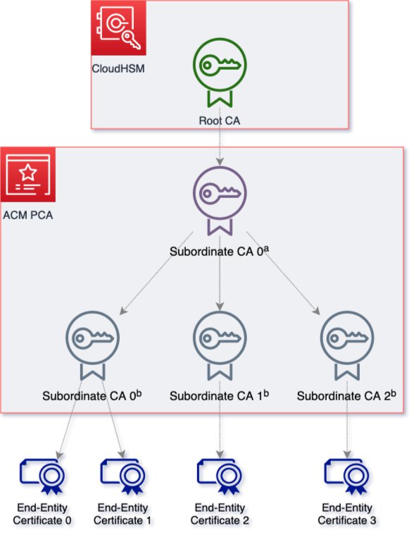
In this post, we show how you can use the AWS Certificate Manager Private Certificate Authority (ACM Private CA) to help follow security best practices when you build a CA hierarchy. This blog post walks through certificate authority (CA) lifecycle management topics, including an architecture overview, centralized security, separation of duties, certificate issuance auditing, and certificate sharing by means of templates. These topics provide best practices surrounding your ACM Private CA hierarchy so that you can build the right CA hierarchy for your organization.

With ACM Private CA, you can create private certificate authority hierarchies, including root and subordinate CAs, without the upfront investment and ongoing maintenance costs of operating your own private CA. You can issue certificates for authenticating internal users, computers, applications, services, servers or other devices, and code signing.

This post includes the following Amazon Web Services (AWS) services:

Solution overview

In this blog post, you’ll see an example automotive manufacturing company and their supplier companies. Each will have associated AWS accounts, which we will call Manufacturer Account(s) and Supplier Account(s), respectively.

Automotive manufacturing companies usually have modules that come from different suppliers. Modules, in the automotive context, are embedded systems that control electrical systems in the vehicle. These modules might be interconnected throughout the in-vehicle network or provide connectivity external to the vehicle, for example, for navigation or sending telemetry to off-board systems.

The architecture needs to allow the Manufacturer to retain control of their CA hierarchy, while giving their external Suppliers limited access to sign the certificates on these modules with the Manufacturer’s CA hierarchy. The architecture we provide here gives you the basic information you need to cover the following objectives:

  1. Creation of accounts that logically separate CAs in a hierarchy
  2. IAM role creation for specific personas to manage the CA lifecycle
  3. Auditing the CA hierarchy by using audit reports
  4. Cross-account sharing by using AWS RAM with certificate template scoping

Architecture overview

Figure 1 shows the solution architecture.

Figure 1: Multi-account certificate authority hierarchy using ACM Private CA

Figure 1: Multi-account certificate authority hierarchy using ACM Private CA

The Manufacturer has two categories of AWS accounts:

  1. A dedicated account to hold the Manufacturer’s root CA
  2. An account to hold their subordinate CA

Note: The diagram shows two subordinate CAs in the Manufacturer account. However, depending on your security needs, you can have a subordinate CA per account per supplier.

Additionally, each Supplier has one AWS account. These accounts will have the Manufacturer’s subordinate CA shared by using AWS RAM. The Manufacturer will have a subordinate CA for each Supplier.

Logically separate accounts

In order to minimize the scope of impact and scope users to actions within their duties, it’s critical that you logically separate AWS accounts based on workload within the CA hierarchy. The following section shows a recommendation for how to do that.

AWS account that holds the root CA

You, the Manufacturer, should place the ACM Private root CA within its own dedicated AWS account to segment and tightly control access to the root CA. This limits access at the account level and only uses the dedicated account for a single purpose: holding the root CA for your organization. This account will only have access from IAM principals that maintain the CA hierarchy through a federation service like AWS Single Sign-On (AWS SSO) or direct federation to IAM through an existing identity provider. This account also has AWS CloudTrail enabled and configured for business-specific alerting, including actions like creation, updating, or deletion of the root CA.

AWS account that holds the subordinate CAs

You, the Manufacturer, will have a dedicated account where the entire CA hierarchy below the root will be located. You should have a separate subordinate CA for each Supplier, and in some cases a separate subordinate CA for each hardware module the Supplier is building. The subordinate CAs can issue certificates for specific hardware modules within the Supplier account.

This Manufacturer account shares each subordinate CA to the respective Supplier’s AWS account by using AWS RAM. This provides joint control to the shared subordinate CA, creating isolation between individual Suppliers. AWS RAM allows Suppliers to control certificate issuance and revocation if this is allowed by the Manufacturer. Each Supplier is only shared certificate provisioning access through AWS RAM configuration, which means that you can tightly monitor and revoke access through AWS RAM. Given this sharing through AWS RAM, the Suppliers don’t have access to modify or delete the CA hierarchy itself and can only provision certificates from it.

Supplier AWS account(s)

These AWS accounts are owned by each respective Supplier. For example, you might partner with radio, navigation system, and telemetry suppliers. Each Supplier would have their own AWS account, which they control. The Supplier accepts an invitation from the manufacturer through AWS RAM, sharing the subordinate CA. The subordinate is allowed to take only certain actions, based on how the Manufacturer configured the share (more on this later in the post).

Separation of duties by means of IAM role creation

In order to follow least privilege best practices when you create a CA hierarchy with ACM Private CA, you must create IAM roles that are specific to each job function. The recommended method is to separate administrator and certificate issuer roles.

For this automotive manufacturing use case, we recommend the following roles:

  1. Manufacturer IAM roles:
    • A CA admin role with CA disable permission
    • A CA admin role with CA delete permission
  2. Supplier certificate issuer IAM role:

Manufacturer IAM role overview

In this flow, one IAM role is able to disable the CA, and a second principal can delete the CA. This enables two-person control for this highly privileged action—meaning that you need a two-person quorum to rotate the CA certificate.

Day-to-day CA admin policy (with CA disable)

{
    "Version": "2012-10-17",
    "Statement": [
        {
            "Effect": "Allow",
            "Action": [
                "acm-pca:ImportCertificateAuthorityCertificate",
                "acm-pca:DeletePolicy",
                "acm-pca:PutPolicy",
                "acm-pca:TagCertificateAuthority",
                "acm-pca:ListTags",
                "acm-pca:GetCertificate",
                "acm-pca:CreateCertificateAuthority",
                "acm-pca:ListCertificateAuthorities",
                "acm-pca:UntagCertificateAuthority",
                "acm-pca:GetCertificateAuthorityCertificate",
                "acm-pca:RevokeCertificate",
                "acm-pca:UpdateCertificateAuthority",
                "acm-pca:GetPolicy",
                "acm-pca:IssueCertificate",
                "acm-pca:DescribeCertificateAuthorityAuditReport",
                "acm-pca:CreateCertificateAuthorityAuditReport",
                "acm-pca:RestoreCertificateAuthority",
                "acm-pca:GetCertificateAuthorityCsr",
                "acm-pca:DeletePermission",
                "acm-pca:DescribeCertificateAuthority",
                "acm-pca:CreatePermission",
                "acm-pca:ListPermissions"
            ],
            "Resource": “*”
        },
        {
            "Effect": "Deny",
            "Action": [
                "acm-pca:DeleteCertificateAuthority"
            ],
            "Resource": <Enter Root CA ARN Here>
        }
    ]
}

Privileged CA admin policy (with CA delete)

{
    "Version": "2012-10-17",
    "Statement": [
        {
            "Effect": "Allow",
            "Action": [
                "acm-pca:ImportCertificateAuthorityCertificate",
                "acm-pca:DeletePolicy",
                "acm-pca:PutPolicy",
                "acm-pca:TagCertificateAuthority",
                "acm-pca:ListTags",
                "acm-pca:GetCertificate",
                "acm-pca:UntagCertificateAuthority",
                "acm-pca:GetCertificateAuthorityCertificate",
                "acm-pca:RevokeCertificate",
                "acm-pca:GetPolicy",
    "acm-pca:CreateCertificateAuthority",
                "acm-pca:ListCertificateAuthorities",
                "acm-pca:DescribeCertificateAuthorityAuditReport",
                "acm-pca:CreateCertificateAuthorityAuditReport",
                "acm-pca:RestoreCertificateAuthority",
                "acm-pca:GetCertificateAuthorityCsr",
                "acm-pca:DeletePermission",
    "acm-pca:IssueCertificate",
                "acm-pca:DescribeCertificateAuthority",
                "acm-pca:CreatePermission",
                "acm-pca:ListPermissions",
                "acm-pca:DeleteCertificateAuthority"
            ],
            "Resource": “*”
        },
        {
            "Effect": "Deny",
            "Action": [
                "acm-pca:UpdateCertificateAuthority"
            ],
            "Resource": <Enter Root CA ARN Here>
        }
    ]
}

We recommend that you, the Manufacturer, create a two-person process for highly privileged events like CA certificate rotation ceremonies. The preceding policies serve two purposes. First, they allow you to designate separation of management duties between day-to-day CA admin tasks and infrequent root CA rotation ceremonies. The day-to-day CA admin policy allows all ACM Private CA actions except the ability to delete the root CA. This is because the day-to-day CA admin should not be deleting the root CA. Meanwhile, the privileged CA admin policy has the ability to call DeleteCertificateAuthority. However, in order to call DeleteCertificateAuthority, you first need to have the day-to-day CA admin role disable the root CA.

This means that both roles listed here are necessary to perform a root CA deletion for a rotation or replacement ceremony. This arrangement creates a way to control the deletion of the CA resource by requiring two separate actors to disable and delete. It’s crucial that the two roles are assumed by two different people at the identity provider. Having one person assume both of these roles negates the increased security created by each role.

You might also consider enforcing tagging of CAs at the organization level so that each new CA has relevant tags. The blog post Securing resource tags used for authorization using a service control policy in AWS Organizations illustrates in detail how to secure tags using service control policies (SCPs), so that only authorized users can modify tags.

Supplier IAM role overview

Your Suppliers should also follow least privilege when creating IAM roles within their own accounts. However, as we’ll see in the Cross-account sharing by using AWS RAM section, even if the Suppliers don’t follow best practices, the Manufacturer’s ACM Private CA hierarchy is still isolated and secure.

That being said, here are common IAM roles that your Suppliers should create within their own accounts:

  1. Developers who provision certificates for development and QA workloads
  2. Developers who provision certificates for production

These certificate issuing roles give the Supplier the ability to issue end-entity certificates from the CA hierarchy. In this use case, the Supplier needs two different levels of permissions: non-production certificates and production certificates. To simplify the roles within IAM, the Supplier decided to use ABAC. These ABAC policies allow operations when the principal’s tag matches the resource tag. Because the Supplier has many similar policies, each with a different set of users, they use ABAC to create a single IAM policy that uses principal tags rather than creating multiple slightly different IAM policies.

Certificate issuing policy that uses ABAC

{
	"Version": "2012-10-17",
	"Statement": [
	{
		"Effect": "Allow",
		"Action": [
			"acm-pca:IssueCertificate",
			"acm-pca:ListTags",
			"acm-pca:GetCertificate",
			"acm-pca:ListCertificateAuthorities"
		],
		"Resource": "*",
		"Condition": {
			"StringEquals": {
				"aws:ResourceTag/access-project": "${aws:PrincipalTag/access-project}",
				"aws:ResourceTag/access-team": "${aws:PrincipalTag/access-team}"
			}
		}
	}
}

This single policy enables all personas to be scoped to least privilege access. If you look at the Condition portion of the IAM policy, you can see the power of ABAC. This condition verifies that the PrincipalTag matches the ResourceTag. The Supplier is federating into IAM roles through AWS SSO and tagging the Supplier’s principals within its selected identity providers.

Because you as the Manufacturer have tagged the subordinate CAs that are shared with the Supplier, the Supplier can use identity provider (IdP) attributes as tags to simplify the Supplier’s IAM strategy. In this example, the Supplier configures each relevant user in the IdP with the attribute (tag) key: access-team. This tag matches the tagging strategy used by the Manufacturer. Here’s the mapping for each persona within the use case:

  • Dev environment:
    • access-team: DevTeam
  • Production environment:
    • access-team: ProdTeam

You can choose to add or remove tags depending on your use case, and the preceding scenario serves as a simple example. This offloads the need to create new IAM policies as the number of subordinate CAs grow. If you decide to use ABAC, make sure that you require both principal tagging and resource tagging upon creation of each, because these tags become your authorization mechanism.

CA lifecycle: Audit report published by the Manufacturer

In terms of auditing and monitoring, we recommend that the Manufacturer have a mechanism to track how many certificates were issued for a specific Supplier or module. Within the Manufacturer accounts, you can generate audit reports through the console or CLI. This allows you, the manufacturer, to gather metrics on certificate issuance and revocation. Following is an example of a certificate issuance.

Figure 2: Audit report output for certificate issuance

Figure 2: Audit report output for certificate issuance

For more information on generating an audit report, see Using audit reports with your private CA.

Cross-account sharing by using AWS RAM

With AWS RAM, you can share CAs with another account. We recommend that you, as a Manufacturer, use AWS RAM to share CAs with Suppliers so that they can issue certificates without administrator access to the CA. This arrangement allows you as the Manufacturer to more easily limit and revoke access if you change Suppliers. The Suppliers can create certificates through the ACM console or through the CLI, API, or AWS CloudFormation. Manufacturers are only sharing the ability to create, manage, bind, and export certificates from the CA hierarchy. The CA hierarchy itself is contained within the Manufacturers’ accounts, and not within the Suppliers’ accounts. By using AWS RAM, the Suppliers don’t have any administrator access to the CA hierarchy. From a cost perspective, you can centrally control and monitor the costs of your private CA hierarchy without having to deal with cost-sharing across Suppliers.

Refer to How to use AWS RAM to share your ACM Private CA cross-account for a full walkthrough on how to use RAM with ACM Private CA.

Certificate templates with AWS RAM managed permissions

AWS RAM has the ability to create managed permissions in order to define the actions that can be performed on shared resources. For each shareable resource type, you can use AWS RAM managed permissions to define which permissions to grant to whom for shared resource types that support additional managed permissions. This means that when you use AWS RAM to share a resource (in this case ACM Private CA), you can now specify which IAM actions can take place on that resource. AWS RAM managed permissions integrate with the following ACM Private CA certificate templates:

  • Permission 1: BlankEndEntityCertificate_APICSRPassthrough
  • Permission 2: EndEntityClientAuthCertificate
  • Permission 3: EndEntityServerAuthCertificate
  • Permission 4: subordinatesubordinateCACertificate_PathLen0
  • Permission 5: RevokeCertificate

These five certificate templates allow a Manufacturer to scope its Suppliers to the certificate template provisioning level. This means that you can limit which certificate templates can be issued by the Suppliers.

Let’s assume you have a Supplier that is supplying a module that has infotainment media capability, and you, the manufacturer, want the Supplier to provision the end-entity client certificate but you don’t want them to be able to revoke that certificate. You can use AWS RAM managed permissions to scope that Supplier’s shared private CA to allow the EndEntityClientAuthCertificate issuance template, which implicitly denies RevokeCertificate template actions. This further scopes down what the Supplier is authorized to issue on the shared CA, gives the responsibility for revoking infotainment device certificates to the Manufacturer, but still allows the Supplier to load devices with a certificate upon creation.

Example of creating a resource share in AWS RAM by using the AWS CLI

This walkthrough shows you the general process of sharing a private CA by using AWS RAM and then accepting that shared resource in the partner account.

  1. Create your shared resource in AWS RAM from the Manufacturer subordinate CA account. Notice that in the example that follows, we selected one of the certificate templates within the managed permissions option. This limits the shared CA so that it can only issue certain types of certificate templates.

    Note: Replace the <variable> placeholders with your own values.

    aws ram create-resource-share
    		--name Shared_Private_CA
    		--resource-arns arn:aws:acm-pca:<region:111122223333>:certificate-authority/<xxxx-xxxx-xxxx-xxxx-example>
    		--permission-arns "arn:aws:ram::aws:permission/<AWSRAMBlankEndEntityCertificateAPICSRPassthroughIssuanceCertificateAuthority>"
    		--principals <444455556666>

  2. From the Supplier account, the Supplier administrator will accept the resource. Follow How to use AWS RAM to share your ACM Private CA cross-account to complete the shared resource acceptance and issue an end entity certificate.

Conclusion

In this blog post, you learned about the various considerations for building a secure public key infrastructure (PKI) hierarchy by using ACM Private CA through an example customer’s prescriptive setup. You learned how you can use AWS RAM to share CAs across accounts easily and securely. You also learned about sharing specific CAs through the ability to define permissions to specific principals across accounts, allowing for granular control of permissions on principals that might act on those resources.

The main takeaways of this post are how to create least privileged roles within IAM in order to scope down the activities of each persona and limit the potential scope of impact for your organization’s private CA hierarchy. Although these best practices are specific to manufacturer business requirements, you can alter them based on your business needs. With the managed permissions in AWS RAM, you can further scope down the actions that principals can perform with your CA by limiting the certificate templates allowed on that CA when you share it. Using all of these tools, you can help your PKI hierarchy to have a high level of security. To learn more, see the other ACM Private CA posts on the AWS Security Blog.

 
If you have feedback about this post, submit comments in the Comments section below. If you have questions about this post, contact AWS Support.

Want more AWS Security news? Follow us on Twitter.

Anthony Pasquariello

Anthony Pasquariello

Anthony is a Senior Solutions Architect at AWS based in New York City. He specializes in modernization and security for our advanced enterprise customers. Anthony enjoys writing and speaking about all things cloud. He’s pursuing an MBA, and received his MS and BS in Electrical & Computer Engineering.

Omar Zoma

Omar Zoma

Omar is a senior AWS Security Solutions Architect that lives in metro Detroit. Omar is passionate about helping customers solve cloud and vehicle security problems at a global scale. In his free time, Omar trains hundreds of students a year in security and cloud through universities and training programs.

Use Amazon Cognito to add claims to an identity token for fine-grained authorization

Post Syndicated from Ajit Ambike original https://aws.amazon.com/blogs/security/use-amazon-cognito-to-add-claims-to-an-identity-token-for-fine-grained-authorization/

With Amazon Cognito, you can quickly add user sign-up, sign-in, and access control to your web and mobile applications. After a user signs in successfully, Cognito generates an identity token for user authorization. The service provides a pre token generation trigger, which you can use to customize identity token claims before token generation. In this blog post, we’ll demonstrate how to perform fine-grained authorization, which provides additional details about an authenticated user by using claims that are added to the identity token. The solution uses a pre token generation trigger to add these claims to the identity token.

Scenario

Imagine a web application that is used by a construction company, where engineers log in to review information related to multiple projects. We’ll look at two different ways of designing the architecture for this scenario: a standard design and a more optimized design.

Standard architecture

A sample standard architecture for such an application is shown in Figure 1, with labels for the various workflow steps:

  1. The user interface is implemented by using ReactJS (a JavaScript library for building user interfaces).
  2. The user pool is configured in Amazon Cognito.
  3. The back end is implemented by using Amazon API Gateway.
  4. AWS Lambda functions exist to implement business logic.
  5. The AWS Lambda CheckUserAccess function (5) checks whether the user has authorization to call the AWS Lambda functions (4).
  6. The project information is stored in an Amazon DynamoDB database.
Figure 1: Lambda functions that need the user’s projectID call the GetProjectID Lambda function

Figure 1: Lambda functions that need the user’s projectID call the GetProjectID Lambda function

In this scenario, because the user has access to information from several projects, several backend functions use calls to the CheckUserAccess Lambda function (step 5 in Figure 1) in order to serve the information that was requested. This will result in multiple calls to the function for the same user, which introduces latency into the system.

Optimized architecture

This blog post introduces a new optimized design, shown in Figure 2, which substantially reduces calls to the CheckUserAccess API endpoint:

  1. The user logs in.
  2. Amazon Cognito makes a single call to the PretokenGenerationLambdaFunction-pretokenCognito function.
  3. The PretokenGenerationLambdaFunction-pretokenCognito function queries the Project ID from the DynamoDB table and adds that information to the Identity token.
  4. DynamoDB delivers the query result to the PretokenGenerationLambdaFunction-pretokenCognito function.
  5. This Identity token is passed in the authorization header for making calls to the Amazon API Gateway endpoint.
  6. Information in the identity token claims is used by the Lambda functions that contain business logic, for additional fine-grained authorization. Therefore, the CheckUserAccess function (7) need not be called.

The improved architecture is shown in Figure 2.

Figure 2. Get the projectID and inset it in a custom claim in the Identity token

Figure 2. Get the projectID and inset it in a custom claim in the Identity token

The benefits of this approach are:

  1. The number of calls to get the Project ID from the DynamoDB table are reduced, which in turn reduces overall latency.
  2. The dependency on the CheckUserAccess Lambda function is removed from the business logic. This reduces coupling in the architecture, as depicted in the diagram.

In the code sample provided in this post, the user interface is run locally from the user’s computer, for simplicity.

Code sample

You can download a zip file that contains the code and the AWS CloudFormation template to implement this solution. The code that we provide to illustrate this solution is described in the following sections.

Prerequisites

Before you deploy this solution, you must first do the following:

  1. Download and install Python 3.7 or later.
  2. Download the AWS SDK for Python (Boto3) library by using the following pip command.
    pip install boto3
  3. Install the argparse package by using the following pip command.
    pip install argparse
  4. Install the AWS Command Line Interface (AWS CLI).
  5. Configure the AWS CLI.
  6. Download a code editor for Python. We used Visual Studio Code for this post.
  7. Install Node.js.

Description of infrastructure

The code provided with this post installs the following infrastructure in your AWS account.

Resource Description
Amazon Cognito user pool The users, added by the addUserInfo.py script, are added to this pool. The client ID is used to identify the web client that will connect to the user pool. The user pool domain is used by the web client to request authentication of the user.
Required AWS Identity and Access Management (IAM) roles and policies Policies used for running the Lambda function and connecting to the DynamoDB database.
Lambda function for the pre token generation trigger A Lambda function to add custom claims to the Identity token.
DynamoDB table with user information A sample database to store user information that is specific to the application.

Deploy the solution

In this section, we describe how to deploy the infrastructure, save the trigger configuration, add users to the Cognito user pool, and run the web application.

To deploy the solution infrastructure

  1. Download the zip file to your machine. The readme.md file in the addclaimstoidtoken folder includes a table that describes the key files in the code.
  2. Change the directory to addclaimstoidtoken.
    cd addclaimstoidtoken
  3. Review stackInputs.json. Change the value of the userPoolDomainName parameter to a random unique value of your choice. This example uses pretokendomainname as the Amazon Cognito domain name; you should change it to a unique domain name of your choice.
  4. Deploy the infrastructure by running the following Python script.
    python3 setup_pretoken.py

    After the CloudFormation stack creation is complete, you should see the details of the infrastructure created as depicted in Figure 3.

    Figure 3: Details of infrastructure

    Figure 3: Details of infrastructure

Now you’re ready to add users to your Amazon Cognito user pool.

To add users to your Cognito user pool

  1. To add users to the Cognito user pool and configure the DynamoDB store, run the Python script from the addclaimstoidtoken directory.
    python3 add_user_info.py
  2. This script adds one user. It will prompt you to provide a username, email, and password for the user.

    Note: Because this is sample code, advanced features of Cognito, like multi-factor authentication, are not enabled. We recommend enabling these features for a production application.

    The addUserInfo.py script performs two actions:

    • Adds the user to the Cognito user pool.
      Figure 4: User added to the Cognito user pool

      Figure 4: User added to the Cognito user pool

    • Adds sample data to the DynamoDB table.
      Figure 5: Sample data added to the DynamoDB table named UserInfoTable

      Figure 5: Sample data added to the DynamoDB table named UserInfoTable

Now you’re ready to run the application to verify the custom claim addition.

To run the web application

  1. Change the directory to the pre-token-web-app directory and run the following command.
    cd pre-token-web-app
  2. This directory contains a ReactJS web application that displays details of the identity token. On the terminal, run the following commands to run the ReactJS application.
    npm install
    npm start

    This should open http://localhost:8081 in your default browser window that shows the Login button.

    Figure 6: Browser opens to URL http://localhost:8081

    Figure 6: Browser opens to URL http://localhost:8081

  3. Choose the Login button. After you do so, the Cognito-hosted login screen is displayed. Log in to the website with the user identity you created by using the addUserInfo.py script in step 1 of the To add users to your Cognito user pool procedure.
    Figure 7: Input credentials in the Cognito-hosted login screen

    Figure 7: Input credentials in the Cognito-hosted login screen

  4. When the login is successful, the next screen displays the identity and access tokens in the URL. You can reveal the token details to verify that the custom claim has been added to the token by choosing the Show Token Detail button.
    Figure 8: Token details displayed in the browser

    Figure 8: Token details displayed in the browser

What happened behind the scenes?

In this web application, the following steps happened behind the scenes:

  1. When you ran the npm start command on the terminal command line, that ran the react-scripts start command from package.json. The port number (8081) was configured in the pre-token-web-app/.env file. This opened the web application that was defined in app.js in the default browser at the URL http://localhost:8081.
  2. The Login button is configured to navigate to the URL that was defined in the constants.js file. The constants.js file was generated during the running of the setup_pretoken.py script. This URL points to the Cognito-hosted default login user interface.
  3. When you provided the login information (username and password), Amazon Cognito authenticated the user. Before generating the set of tokens (identity token and access token), Cognito first called the pre-token-generation Lambda trigger. This Lambda function has the code to connect to the DynamoDB database. The Lambda function can then access the project information for the user that is stored in the userInfo table. The Lambda function read this project information and added it to the identity token that was delivered to the web application.

    Lambda function code

    const AWS = require("aws-sdk");
    
    // Create the DynamoDB service object
    var ddb = new AWS.DynamoDB({ apiVersion: "2012-08-10" });
    
    // PretokenGeneration Lambda
    exports.handler = async function (event, context) {
        var eventUserName = "";
        var projects = "";
    
        if (!event.userName) {
            return event;
        }
    
        var params = {
            ExpressionAttributeValues: {
                ":v1": {
                    S: event.userName
                }
            },
            KeyConditionExpression: "userName = :v1",
            ProjectionExpression: "projects",
            TableName: "UserInfoTable"
        };
    
        event.response = {
            "claimsOverrideDetails": {
                "claimsToAddOrOverride": {
                    "userName": event.userName,
                    "projects": null
                },
            }
        };
    
        try {
            let result = await ddb.query(params).promise();
            if (result.Items.length > 0) {
                const projects = result.Items[0]["projects"]["S"];
                console.log("projects = " + projects);
                event.response.claimsOverrideDetails.claimsToAddOrOverride.projects = projects;
            }
        }
        catch (error) {
            console.log(error);
        }
    
        return event;
    };

    The code for the Lambda function is as follows.

  4. After a successful login, Amazon Cognito redirected to the URL that was specified in the App Client Settings section, and added the token to the URL.
  5. The webpage detected the token in the URL and displayed the Show Token Detail button. When you selected the button, the webpage read the token in the URL, decoded the token, and displayed the information in the relevant text boxes.
  6. Notice that the Decoded ID Token box shows the custom claim named projects that displays the projectID that was added by the PretokenGenerationLambdaFunction-pretokenCognito trigger.

How to use the sample code in your application

We recommend that you use this sample code with the following modifications:

  1. The code provided does not implement the API Gateway and Lambda functions that consume the custom claim information. You should implement the necessary Lambda functions and read the custom claim for the event object. This event object is a JSON-formatted object that contains authorization data.
  2. The ReactJS-based user interface should be hosted on an Amazon Simple Storage Service (Amazon S3) bucket.
  3. The projectId of the user is available in the token. Therefore, when the token is passed by the Authorization trigger to the back end, this custom claim information can be used to perform actions specific to the project for that user. For example, getting all of that user’s work items that are related to the project.
  4. Because the token is valid for one hour, the information in the custom claim information is available to the user interface during that time.
  5. You can use the AWS Amplify library to simplify the communication between your web application and Amazon Cognito. AWS Amplify can handle the token retention and refresh token mechanism for the web application. This also removes the need for the token to be displayed in the URL.
  6. If you’re using Amazon Cognito to manage your users and authenticate them, using the Amazon Cognito user pool to control access to your API is easier, because you don’t have to write the authentication code in your authorizer.
  7. If you decide to use Lambda authorizers, note the following important information from the topic Steps to create an API Gateway Lambda authorizer: “In production code, you may need to authenticate the user before granting authorization. If so, you can add authentication logic in the Lambda function as well by calling an authentication provider as directed in the documentation for that provider.”
  8. Lambda authorizer is recommended if the final authorization (not just token validity) decision is made based on custom claims.

Conclusion

In this blog post, we demonstrated how to implement fine-grained authorization based on data stored in the back end, by using claims stored in an identity token that is generated by the Amazon Cognito pre token generation trigger. This solution can help you achieve a reduction in latency and improvement in performance.

For more information on the pre token generation Lambda trigger, refer to the Amazon Cognito Developer Guide.

 
If you have feedback about this post, submit comments in the Comments section below. If you have questions about this post, contact AWS Support.

Want more AWS Security news? Follow us on Twitter.

Ajit Ambike

Ajit Ambike

Ajit Ambike is a Sr. Application Architect at Amazon Web Services. As part of AWS Energy team, he leads the creation of new business capabilities for the customers. Ajit also brings best practices to the customers and partners that accelerate the productivity of their teams.

Zafar Kapadia

Zafar Kapadia

Zafar Kapadia is a Sr. Customer Delivery Architect at AWS. He has over 17 years of IT experience and has worked on several Application Development and Optimization projects. He is also an avid cricketer and plays in various local leagues.

How to use AWS KMS RSA keys for offline encryption

Post Syndicated from Patrick Palmer original https://aws.amazon.com/blogs/security/how-to-use-aws-kms-rsa-keys-for-offline-encryption/

This blog post discusses how you can use AWS Key Management Service (AWS KMS) RSA public keys on end clients or devices and encrypt data, then subsequently decrypt data by using private keys that are secured in AWS KMS.

Asymmetric cryptography is a cryptographic system that uses key pairs. Each pair consists of a public key, which can be seen or accessed by anyone, and a private key, which can be accessed only by authorized people. This system has a useful property, which is that anything encrypted with a public key can only be decrypted by the corresponding private key. A popular method for generating key pairs and encrypting data is the RSA algorithm and cryptosystem.

For RSA key pairs, calculating the private key from the public key is seen as computationally infeasible, and therefore RSA key pairs can be used for both authentication and encryption. The features of asymmetric encryption allow separated parties to share information across an untrusted domain, such as the internet, without having to pre-share any other secrets. However, this type of encryption poses an issue of keeping the private key secure, because the private key has the power to decrypt all messages that are transmitted by a large number of end users.

AWS KMS provides simple APIs that you can use to securely generate, store, and manage keys, including RSA key pairs inside hardware security modules (HSMs). Key pairs are generated within FIPS 140-2 validated HSMs that are managed by AWS. You can then use these private keys through APIs to do actions such as decrypt ciphertexts, meaning that plaintext private keys never leave the HSM, which provides assurances of privacy for the private key. Additional APIs allow a customer to retrieve a plaintext copy of the corresponding public key, which allows disconnected or offline uses of RSA public keys.

Limits of asymmetric cryptography

A key drawback to asymmetric cryptography is the fact that you cannot encrypt large pieces of data. When you have a 2048-bit RSA key pair and encrypt something by using the cipher RSAES_OASEP_SHA_256, the largest amount of data that you can encrypt is 190 bytes.

In contrast, symmetric encryption ciphers that use a chained or counter-mode operation don’t have this limit, and they make it possible for you to encrypt data in the tens-of-gigabytes. Symmetric encryption algorithms such as the Advanced Encryption Standard (AES) also benefit from faster data encryption speeds due to smaller key sizes and less complex operations that can be built into hardware.

By combining these two algorithms in a hybrid cryptosystem, you give end clients with a public key the ability to encrypt large pieces of information. A client generates a random 256-bit AES key, which should be from a secure source such as /dev/urandom or a dedicated embedded chip. The client then encrypts its large payload by using a mode of operation such as AES-GCM or AES-CBC by using that 256-bit AES key. Next, the client encrypts that 256-bit AES key by using the RSA public key (see step 5 in Figure 1). End clients then transmit only encrypted data across insecure channels, maintaining privacy of the payload data.

A challenge that customers often face is that they want to use AWS KMS for its security properties, but also want to access their KMS keys from devices that don’t have AWS credentials embedded within them. Without AWS credentials, a device can’t call AWS APIs. This blog post shows how you can use a hybrid cryptosystem where RSA public keys can be downloaded or embedded into devices to overcome this challenge.

Prerequisites and initial considerations

This walkthrough assumes that you have some understanding of RSA ciphers and symmetric encryption schemes such as AES. The walkthrough uses OpenSSL for demonstration of the encryption process, but similar libraries can be used on a client-side device.

The walkthrough also assumes that you have an AWS Identity and Access Management (IAM) user with permissions to the AWS KMS service, and the AWS Command Line Interface (AWS CLI) installed with the relevant credentials.

When you create a KMS key, you will also generate a key policy that defines access to it. The default key policy allows all users in your account with AWS KMS actions in their IAM policies to access the KMS key. The key policy for a given KMS key is the primary method for determining access.

Important: You will incur charges for the services used in this example. You can find the cost of each service on the corresponding service pricing page. For more information, see AWS KMS Pricing.

Architectural overview

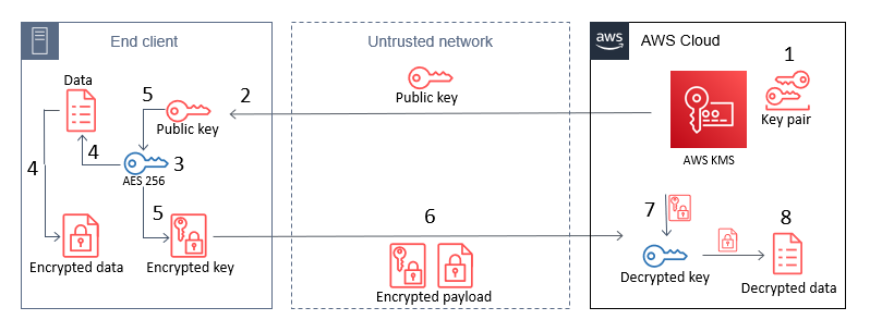
This post contains procedures for completing the following operations, which are also shown in Figure 1:

  1. Create an RSA key pair in AWS KMS.
  2. Download or pre-install the AWS KMS public key to an end-client device.
  3. Generate an AES 256-bit key on an end client.
  4. Encrypt a large payload of data on the end client by using the AES 256-bit key.
  5. Encrypt the AES 256-bit key with the AWS KMS public key.
  6. Transfer the encrypted payload and key.
  7. Decrypt the AES 256-bit key by using AWS KMS.
  8. Decrypt the payload data by using the now-shared AES 256-bit key.
Figure 1: The steps for hybrid encryption

Figure 1: The steps for hybrid encryption

This diagram shows an end client device, an untrusted network such as a cellular network, and the AWS Cloud. An RSA key pair is generated in AWS KMS, and then the public key can either be embedded in the end client, or pulled by the end client through HTTP(S) or other remote means. In all circumstances, only the public key persists on the end client, which means that no secrets are stored on the device.

How you host the public key on your end clients depends on what network access they have. For example, an embedded Internet of Things (IoT) device for mining vehicles might never connect to the internet, but could communicate with a central system through a private 5G network. In this circumstance, you would host this public key within that network for retrieval. For other disconnected IoT devices that can connect to the internet, such as smart-home appliances, you might want to host the public key on a web server at a predefined URL or through an API.

Note: Whenever you vend public keys over an untrusted channel, such as when you vend the public key through an API, you should make sure that the key can be verified in some way to confirm that it hasn’t been tampered with. This is typically done by vending keys over an HTTPS connection, where the integrity of the keys is provided by the X.509 certificate that was used in the TLS connection. The X.509 certificate also verifies an association with the key-pair owner, typically by domain name.

Implement the solution

The following steps can be used as a proof-of-concept to guide you through implementing a hybrid-cryptosystem by using a KMS public key on an example device.

Create keys in AWS KMS

In the first step of this solution, you create an RSA asymmetric key pair in AWS KMS (step 1 in the architectural overview). With AWS KMS, you can create key pairs in a variety of dimensions according to your security requirements or standards. For more information, see Choosing a KMS key type in the AWS KMS documentation.

To create a key pair in AWS KMS, use the CreateKey API. For this example, you will create an RSA key pair with RSA_2048 for the CustomerMasterKeySpec parameter and ENCRYPT_DECRYPT for the KeyUsage parameter in the AWS CLI. This post uses 2048-bit keys, but note that AWS KMS allows larger key sizes. The CLI will return a KeyId value that uniquely identifies the KMS key in your account, which you should take note of.

To create a KMS key by using the CLI

  • Enter the following command in the AWS CLI.
    aws kms create-key --key-spec RSA_2048 \
        --key-usage ENCRYPT_DECRYPT \
        --description "Example RSA Encryption Key Pair"

You can follow the Creating asymmetric KMS keys documentation to see how to use the AWS Management Console to create a KMS key pair with the same properties as shown here.

Note: When a KMS key is created, it will be logged by AWS CloudTrail, a service that monitors and records activity within your account. All API calls to the AWS KMS service are logged in CloudTrail, which you can use to audit access to KMS keys.

To allow your KMS key to be identified by a human-readable string rather than KeyId, you can assign an alias for the KMS key (replace the target-key-id value of <1234abcd-12ab-34cd-56ef-1234567890ab> with your KeyId). This makes it easier to use and manage.

To create a KMS key alias for your key by using the CLI

  • Enter the following command in the AWS CLI.
    aws kms create-alias \
        --alias-name alias/example-rsa-key \
        --target-key-id <1234abcd-12ab-34cd-56ef-1234567890ab>
    

Download the public key from AWS KMS

A benefit of asymmetric encryption is that you can distribute a public key to a large, untrusted network, and the public key can only be used for encryption. Decryption of those messages can only be conducted by the corresponding private key. You can use the AWS KMS Encrypt API to encrypt data with a KMS key pair (specifically the public key). However, because the AWS APIs are authenticated by using a signature, you must have access to AWS credentials to use these APIs, which you might not want to do on untrusted devices. Additionally, in a private 5G network, you might not have the capability to call the AWS KMS API endpoints from the end clients. Instead, you can download the public key from a local source or embed that into the end client at the time of manufacture.

To retrieve a copy of the public key from your AWS KMS key pair, you can use the GetPublicKey API. The following example shows how to use this with the AWS CLI command get-public-key and reference the key alias you set earlier.

To view the public key for your KMS key pair by using the CLI

  • Enter the following command in the AWS CLI.
    aws kms get-public-key --key-id alias/example-rsa-key

The return value from this API will contain several elements, including the PublicKey. The returned PublicKey value is the DER-encoded X.509, and because you’re using the AWS CLI, it is base64-encoded for readability purposes. By using the AWS CLI, you can query just the PublicKey return value, base64-decode it, and then save the key to a file on disk, as follows.

To use the AWS CLI to query only the public key, then base64 decode it and output it to a file

  • Enter the following command in the AWS CLI.
    aws kms get-public-key \
    --key-id alias/example-rsa-key \ 
    --output text \ 
    --query PublicKey | base64 -–decode > public_key.der

In this example, the local machine where you saved the public_key.der file will now represent the end-client device.

Note: If you call this API by using one of the AWS SDKs, such as boto3, then the PublicKey value is not base64-encoded.

Create an AES 256-bit symmetric key on the end client

Although the end client now has a copy of the public key from the associated KMS private key, the public key can’t be used for encrypting data that you plan on transmitting, due to the size limits on data that can be encrypted. Instead, you can use symmetric encryption. Typically, symmetric keys are smaller than asymmetric keys, the ciphers are faster when encrypting data, and the resulting ciphertext is similar in size to the original data.

To generate a symmetric key, you should use a source of random entropy. Some operating systems offer block access to hardware-based sources of random numbers, such as /dev/hwrng. To provide an example process in this blog post, you will use the OpenSSL rand utility, which uses a cryptographically secure pseudo random generator (CSPRNG) seeded by /dev/urandom. In production systems, you might have stronger sources of entropy to rely on, or compliance requirements for random number generation. In hardware-constrained environments, you should take extra care to make sure that sources of entropy are cryptographically secure. The following command uses OpenSSL to create an AES 256-bit (32 bytes) key and base64-encode it, then save it to disk in plaintext as key.b64.

Note: Anyone with access to this file system will have access to this key.

To use the OpenSSL rand command to create a symmetric key and output it to a file

  • Enter the following command.
    openssl rand -base64 32 > key.b64

Encrypt the data to be sent from the end client

Now that you have two different key types on the end client, you can use a hybrid cryptosystem to encrypt a large text file. First, you will generate a sample file to encrypt on your system. By outputting some bytes from /dev/urandom, you can create this file to the size you want. The following command outputs 200 random bytes, base64-encodes the file, and writes that to disk in a file called encrypt.me.

To generate a sample file from random data, which will be encrypted later

  • Enter the following command.
    head -c 200 /dev/urandom | base64 –-wrap=0 > encrypt.me

Next, you will encrypt the newly created file with the AES 256-bit key that you created earlier (which is base64-encoded). By using the OpenSSL command line, you will encrypt the file on disk and create a new file called encrypt.me.enc.

Note: For demonstration purposes, this solution uses OpenSSL to complete the encryption process. However, the command line OpenSSL enc utility doesn’t allow the cipher aes-256-gcm. Galois Counter Mode (GCM) is recommended when encrypting and sending data, because it includes authentication, so that that the ciphertext can’t be tampered with in transit. Instead, for this demonstration, you will use aes-256-cbc, which is not authenticated.

To use the OpenSSL enc command to encrypt your sample file with a symmetric key

  • • Enter the following command.
    openssl enc -aes-256-cbc \
    -in encrypt.me -out encrypt.me.enc \
    -pass file:./key.b64

Encrypt the AES 256-bit key

So that the data can be decrypted again, you will need to share the same AES 256-bit key with the recipient. To share that with only the person who can use the KMS private key that you created earlier, you can encrypt the symmetric key (key.b64) with the RSA public key that you retrieved earlier (public_key.der).

Again, you will use OpenSSL to see how this works and the required cipher options. When encrypting or decrypting with a KMS RSA key pair, you can use one of two encryption algorithms, either RSAES_OAEP_SHA_1 or RSAES_OAEP_SHA_256. These identify the cipher suites used in encryption that are currently supported by AWS KMS for encryption.

To use the OpenSSL pkeyutl command to encrypt your symmetric key with your local copy of your KMS public key

  • Enter the following command.
    openssl pkeyutl \
    	-in key.b64 -out key.b64.enc \
    	-inkey public_key.der -keyform DER -pubin -encrypt \
    	-pkeyopt rsa_padding_mode:oaep -pkeyopt rsa_oaep_md:sha256

This command creates a new file on disk called key.b64.enc. This file is the encrypted AES 256-bit key, which can now be transported securely across an insecure network, such as the internet. The last two options in the command define the padding mode used (OAEP) and the length of the message digest (SHA-256), which align with the options available to decrypt when you use the AWS KMS APIs.

Note: You should securely delete both the original payload file (encrypt.me) and the plaintext AES 256-bit key (key.b64) if you want to prevent anyone else from accessing these files. At this point, you will have three files on disk: public_key.der, encrypt.me.enc, and key.b64.enc. If you want to verify the decryption process later in this example, keep these files.

In production, you might never write any of these values to disk. Instead, you can keep all values in memory and only write the encrypted data (ciphertext) to disk, clearing memory after that process has completed.

You can now use the method of your choice to transfer the encrypted files across an unsecured network without compromising the privacy of those files. For smart-home appliance use cases, you can upload the encrypted files in Amazon Simple Storage Service (Amazon S3), a highly durable storage system that can be accessed from the internet, keeping in mind the preventative security practices that AWS recommends. Later, another service can pull these files from S3, and with the correct permissions for the KMS key, can decrypt the files by using the AWS KMS Decrypt API.

Decrypt the files

With access to the decrypt operation for the KMS key and the encrypted files, you can now retrieve the plaintext data file again. To do this, you will replicate the preceding steps, but in reverse. This involves decrypting the AWS 256-bit key by using the AWS KMS API, and then using that result to decrypt the encrypted data. You will need access to the AWS KMS API to complete these actions, because the private key exists in plaintext only within the AWS KMS HSMs.

To decrypt the files

  1. The first step is to decrypt the AWS 256-bit key. You will need to use the AWS CLI to submit the key.b64.enc file to the AWS KMS API, and specify the algorithm you used to encrypt the file (RSAES_OAEP_SHA_256). Use the following command to retrieve the AES 256-bit key in plaintext. Again, you’re using the –query selector to output only the plaintext, and then decode the base64 value.
    aws kms decrypt --key-id alias/example-rsa-key \ 
    		--ciphertext-blob fileb://key.b64.enc \
    		--encryption-algorithm RSAES_OAEP_SHA_256 --output text \
    		--query 'Plaintext' | base64 --decode > decrypted_key.b64

  2. The final step in decrypting the data is to reverse the CBC encryption process you used in OpenSSL. If another mode of symmetric encryption was used, such as AES-GCM, then you would need to decrypt by using that algorithm and the input AES 256-bit key. Use the following OpenSSL command to retrieve the original plaintext payload.
    openssl enc -d -aes-256-cbc \
    		-in encrypt.me.enc -out decrypted.file \
    		-pass file:./decrypted_key.b64

Conclusion

In this post, you learned how to combine AWS KMS asymmetric key pairs with locally created symmetric keys to encrypt and share data that exceeds 190 bytes, without storing a secret on a client device. By taking advantage of the RSA cryptosystem for offline encryption, you can reduce the exposure of plaintext data or secrets to devices outside of your control, and without having to complete complex key exchanges. By using the steps in this solution, you can more securely share large amounts of data, such as update files or configuration settings. To learn more about the asymmetric keys feature of AWS KMS, refer to the AWS KMS Developer Guide. If you have questions about the asymmetric keys feature, interact with us through AWS re:Post.

 
If you have feedback about this post, submit comments in the Comments section below. If you have questions about this post, contact AWS Support.

Want more AWS Security news? Follow us on Twitter.

Patrick Palmer

Patrick is a security solutions architect at AWS. He has a passion for learning new technologies and cryptography across AWS services and having deep conversations with customers. He works on a team of security specialists who strive to continually delight customers. Outside of work, he spends time with his wife and two cats, occasionally playing video games when he can.

Manage application security and compliance with the AWS Cloud Development Kit and cdk-nag

Post Syndicated from Rodney Bozo original https://aws.amazon.com/blogs/devops/manage-application-security-and-compliance-with-the-aws-cloud-development-kit-and-cdk-nag/

Infrastructure as Code (IaC) is an important part of Cloud Applications. Developers rely on various Static Application Security Testing (SAST) tools to identify security/compliance issues and mitigate these issues early on, before releasing their applications to production. Additionally, SAST tools often provide reporting mechanisms that can help developers verify compliance during security reviews.

cdk-nag integrates directly into AWS Cloud Development Kit (AWS CDK) applications to provide identification and reporting mechanisms similar to SAST tooling.

This post demonstrates how to integrate cdk-nag into an AWS CDK application to provide continual feedback and help align your applications with best practices.

Overview of cdk-nag

cdk-nag (inspired by cfn_nag) validates that the state of constructs within a given scope comply with a given set of rules. Additionally, cdk-nag provides a rule suppression and compliance reporting system. cdk-nag validates constructs by extending AWS CDK Aspects. If you’re interested in learning more about the AWS CDK Aspect system, then you should check out this post.

cdk-nag includes several rule sets (NagPacks) to validate your application against. As of this post, cdk-nag includes the AWS Solutions, HIPAA Security, NIST 800-53 rev 4, NIST 800-53 rev 5, and PCI DSS 3.2.1 NagPacks. You can pick and choose different NagPacks and apply as many as you wish to a given scope.

cdk-nag rules can either be warnings or errors. Both warnings and errors will be displayed in the console and compliance reports. Only unsuppressed errors will prevent applications from deploying with the cdk deploy command.

You can see which rules are implemented in each of the NagPacks in the Rules Documentation in the GitHub repository.

Walkthrough

This walkthrough will setup a minimal AWS CDK v2 application, as well as demonstrate how to apply a NagPack to the application, how to suppress rules, and how to view a report of the findings. Although cdk-nag has support for Python, TypeScript, Java, and .NET AWS CDK applications, we’ll use TypeScript for this walkthrough.

Prerequisites

For this walkthrough, you should have the following prerequisites:

  • A local installation of and experience using the AWS CDK.

Create a baseline AWS CDK application

In this section you will create and synthesize a small AWS CDK v2 application with an Amazon Simple Storage Service (Amazon S3) bucket. If you are unfamiliar with using the AWS CDK, then learn how to install and setup the AWS CDK by looking at their open source GitHub repository.

  1. Run the following commands to create the AWS CDK application:
mkdir CdkTest
cd CdkTest
cdk init app --language typescript
  1. Replace the contents of the lib/cdk_test-stack.ts with the following:
import { Stack, StackProps } from 'aws-cdk-lib';
import { Construct } from 'constructs';
import { Bucket } from 'aws-cdk-lib/aws-s3';

export class CdkTestStack extends Stack {
  constructor(scope: Construct, id: string, props?: StackProps) {
    super(scope, id, props);
    const bucket = new Bucket(this, 'Bucket')
  }
}
  1. Run the following commands to install dependencies and synthesize our sample app:
npm install
npx cdk synth

You should see an AWS CloudFormation template with an S3 bucket both in your terminal and in cdk.out/CdkTestStack.template.json.

Apply a NagPack in your application

In this section, you’ll install cdk-nag, include the AwsSolutions NagPack in your application, and view the results.

  1. Run the following command to install cdk-nag:
npm install cdk-nag
  1. Replace the contents of the bin/cdk_test.ts with the following:
#!/usr/bin/env node
import 'source-map-support/register';
import * as cdk from 'aws-cdk-lib';
import { CdkTestStack } from '../lib/cdk_test-stack';
import { AwsSolutionsChecks } from 'cdk-nag'
import { Aspects } from 'aws-cdk-lib';

const app = new cdk.App();
// Add the cdk-nag AwsSolutions Pack with extra verbose logging enabled.
Aspects.of(app).add(new AwsSolutionsChecks({ verbose: true }))
new CdkTestStack(app, 'CdkTestStack', {});
  1. Run the following command to view the output and generate the compliance report:
npx cdk synth

The output should look similar to the following (Note: SSE stands for Server-side encryption):

[Error at /CdkTestStack/Bucket/Resource] AwsSolutions-S1: The S3 Bucket has server access logs disabled. The bucket should have server access logging enabled to provide detailed records for the requests that are made to the bucket.

[Error at /CdkTestStack/Bucket/Resource] AwsSolutions-S2: The S3 Bucket does not have public access restricted and blocked. The bucket should have public access restricted and blocked to prevent unauthorized access.

[Error at /CdkTestStack/Bucket/Resource] AwsSolutions-S3: The S3 Bucket does not default encryption enabled. The bucket should minimally have SSE enabled to help protect data-at-rest.

[Error at /CdkTestStack/Bucket/Resource] AwsSolutions-S10: The S3 Bucket does not require requests to use SSL. You can use HTTPS (TLS) to help prevent potential attackers from eavesdropping on or manipulating network traffic using person-in-the-middle or similar attacks. You should allow only encrypted connections over HTTPS (TLS) using the aws:SecureTransport condition on Amazon S3 bucket policies.

Found errors

Note that applying the AwsSolutions NagPack to the application rendered several errors in the console (AwsSolutions-S1, AwsSolutions-S2, AwsSolutions-S3, and AwsSolutions-S10). Furthermore, the cdk.out/AwsSolutions-CdkTestStack-NagReport.csv contains the errors as well:

Rule ID,Resource ID,Compliance,Exception Reason,Rule Level,Rule Info
"AwsSolutions-S1","CdkTestStack/Bucket/Resource","Non-Compliant","N/A","Error","The S3 Bucket has server access logs disabled."
"AwsSolutions-S2","CdkTestStack/Bucket/Resource","Non-Compliant","N/A","Error","The S3 Bucket does not have public access restricted and blocked."
"AwsSolutions-S3","CdkTestStack/Bucket/Resource","Non-Compliant","N/A","Error","The S3 Bucket does not default encryption enabled."
"AwsSolutions-S5","CdkTestStack/Bucket/Resource","Compliant","N/A","Error","The S3 static website bucket either has an open world bucket policy or does not use a CloudFront Origin Access Identity (OAI) in the bucket policy for limited getObject and/or putObject permissions."
"AwsSolutions-S10","CdkTestStack/Bucket/Resource","Non-Compliant","N/A","Error","The S3 Bucket does not require requests to use SSL."

Remediating and suppressing errors

In this section, you’ll remediate the AwsSolutions-S10 error, suppress the  AwsSolutions-S1 error on a Stack level, suppress the  AwsSolutions-S2 error on a Resource level errors, and not remediate the  AwsSolutions-S3 error and view the results.

  1. Replace the contents of the lib/cdk_test-stack.ts with the following:
import { Stack, StackProps } from 'aws-cdk-lib';
import { Construct } from 'constructs';
import { Bucket } from 'aws-cdk-lib/aws-s3';
import { NagSuppressions } from 'cdk-nag'

export class CdkTestStack extends Stack {
  constructor(scope: Construct, id: string, props?: StackProps) {
    super(scope, id, props);
    // The local scope 'this' is the Stack. 
    NagSuppressions.addStackSuppressions(this, [
      {
        id: 'AwsSolutions-S1',
        reason: 'Demonstrate a stack level suppression.'
      },
    ])
    // Remediating AwsSolutions-S10 by enforcing SSL on the bucket.
    const bucket = new Bucket(this, 'Bucket', { enforceSSL: true })
    NagSuppressions.addResourceSuppressions(bucket, [
      {
        id: 'AwsSolutions-S2',
        reason: 'Demonstrate a resource level suppression.'
      },
    ])
  }
}
  1. Run the cdk synth command again:
npx cdk synth

The output should look similar to the following:

[Error at /CdkTestStack/Bucket/Resource] AwsSolutions-S3: The S3 Bucket does not default encryption enabled. The bucket should minimally have SSE enabled to help protect data-at-rest.

Found errors

The cdk.out/AwsSolutions-CdkTestStack-NagReport.csv contains more details about rule compliance, non-compliance, and suppressions.

Rule ID,Resource ID,Compliance,Exception Reason,Rule Level,Rule Info
"AwsSolutions-S1","CdkTestStack/Bucket/Resource","Suppressed","Demonstrate a stack level suppression.","Error","The S3 Bucket has server access logs disabled."
"AwsSolutions-S2","CdkTestStack/Bucket/Resource","Suppressed","Demonstrate a resource level suppression.","Error","The S3 Bucket does not have public access restricted and blocked."
"AwsSolutions-S3","CdkTestStack/Bucket/Resource","Non-Compliant","N/A","Error","The S3 Bucket does not default encryption enabled."
"AwsSolutions-S5","CdkTestStack/Bucket/Resource","Compliant","N/A","Error","The S3 static website bucket either has an open world bucket policy or does not use a CloudFront Origin Access Identity (OAI) in the bucket policy for limited getObject and/or putObject permissions."
"AwsSolutions-S10","CdkTestStack/Bucket/Resource","Compliant","N/A","Error","The S3 Bucket does not require requests to use SSL."

Moreover, note that the resultant cdk.out/CdkTestStack.template.json template contains the cdk-nag suppression data. This provides transparency with what rules weren’t applied to an application, as the suppression data is included in the resources.

{
  "Metadata": {
    "cdk_nag": {
      "rules_to_suppress": [
        {
          "id": "AwsSolutions-S1",
          "reason": "Demonstrate a stack level suppression."
        }
      ]
    }
  },
  "Resources": {
    "BucketDEB6E181": {
      "Type": "AWS::S3::Bucket",
      "UpdateReplacePolicy": "Retain",
      "DeletionPolicy": "Retain",
      "Metadata": {
        "aws:cdk:path": "CdkTestStack/Bucket/Resource",
        "cdk_nag": {
          "rules_to_suppress": [
            {
              "id": "AwsSolutions-S2",
              "reason": "Demonstrate a resource level suppression."
            }
          ]
        }
      }
    },
  ...
  },
  ...
}

Reflecting on the Walkthrough

In this section, you learned how to apply a NagPack to your application, remediate/suppress warnings and errors, and review the compliance reports. The reporting and suppression systems provide mechanisms for the development and security teams within organizations to work together to identify and mitigate potential security/compliance issues. Security can choose which NagPacks developers should apply to their applications. Then, developers can use the feedback to quickly remediate issues. Security can use the reports to validate compliances. Furthermore, developers and security can work together to use suppressions to transparently document exceptions to rules that they’ve decided not to follow.

Advanced usage and further reading

This section briefly covers some advanced options for using cdk-nag.

Unit Testing with the AWS CDK Assertions Library

The Annotations submodule of the AWS CDK assertions library lets you check for cdk-nag warnings and errors without AWS credentials by integrating a NagPack into your application unit tests. Read this post for further information about the AWS CDK assertions module. The following is an example of using assertions with a TypeScript AWS CDK application and Jest for unit testing.

import { Annotations, Match } from 'aws-cdk-lib/assertions';
import { App, Aspects, Stack } from 'aws-cdk-lib';
import { AwsSolutionsChecks } from 'cdk-nag';
import { CdkTestStack } from '../lib/cdk_test-stack';

describe('cdk-nag AwsSolutions Pack', () => {
  let stack: Stack;
  let app: App;
  // In this case we can use beforeAll() over beforeEach() since our tests 
  // do not modify the state of the application 
  beforeAll(() => {
    // GIVEN
    app = new App();
    stack = new CdkTestStack(app, 'test');

    // WHEN
    Aspects.of(stack).add(new AwsSolutionsChecks());
  });

  // THEN
  test('No unsuppressed Warnings', () => {
    const warnings = Annotations.fromStack(stack).findWarning(
      '*',
      Match.stringLikeRegexp('AwsSolutions-.*')
    );
    expect(warnings).toHaveLength(0);
  });

  test('No unsuppressed Errors', () => {
    const errors = Annotations.fromStack(stack).findError(
      '*',
      Match.stringLikeRegexp('AwsSolutions-.*')
    );
    expect(errors).toHaveLength(0);
  });
});

Additionally, many testing frameworks include watch functionality. This is a background process that reruns all of the tests when files in your project have changed for fast feedback. For example, when using the AWS CDK in JavaScript/Typescript, you can use the Jest CLI watch commands. When Jest watch detects a file change, it attempts to run unit tests related to the changed file. This can be used to automatically run cdk-nag-related tests when making changes to your AWS CDK application.

CDK Watch

When developing in non-production environments, consider using AWS CDK Watch with a NagPack for fast feedback. AWS CDK Watch attempts to synthesize and then deploy changes whenever you save changes to your files. Aspects are run during synthesis. Therefore, any NagPacks applied to your application will also run on save. As in the walkthrough, all of the unsuppressed errors will prevent deployments, all of the messages will be output to the console, and all of the compliance reports will be generated. Read this post for further information about AWS CDK Watch.

Conclusion

In this post, you learned how to use cdk-nag in your AWS CDK applications. To learn more about using cdk-nag in your applications, check out the README in the GitHub Repository. If you would like to learn how to create your own rules and NagPacks, then check out the developer documentation. The repository is open source and welcomes community contributions and feedback.

Author:

Arun Donti

Arun Donti is a Senior Software Engineer with Twitch. He loves working on building automated processes and tools that enable builders and organizations to focus on and deliver their mission critical needs. You can find him on GitHub.

A new Spark plugin for CPU and memory profiling

Post Syndicated from Bo Xiong original https://aws.amazon.com/blogs/devops/a-new-spark-plugin-for-cpu-and-memory-profiling/

Introduction

Have you ever wondered if there are low-hanging optimization opportunities to improve the performance of a Spark app? Profiling can help you gain visibility regarding the runtime characteristics of the Spark app to identify its bottlenecks and inefficiencies. We’re excited to announce the release of a new Spark plugin that enables profiling for JVM based Spark apps via Amazon CodeGuru. The plugin is open sourced on GitHub and published to Maven.

Walkthrough

This post shows how you can onboard this plugin with two steps in under 10 minutes.

  • Step 1: Create a profiling group in Amazon CodeGuru Profiler and grant permission to your Amazon EMR on EC2 role, so that profiler agents can emit metrics to CodeGuru. Detailed instructions can be found here.
  • Step 2: Reference codeguru-profiler-for-spark when submitting your Spark job, along with PROFILING_CONTEXT and ENABLE_AMAZON_PROFILER defined.

Prerequisites

Your app is built against Spark 3 and run on Amazon EMR release 6.x or newer. It doesn’t matter if you’re using Amazon EMR on Amazon Elastic Compute Cloud (Amazon EC2) or on Amazon Elastic Kubernetes Service (Amazon EKS).

Illustrative Example

For the purposes of illustration, consider the following example where profiling results are collected by the plugin and emitted to the “CodeGuru-Spark-Demo” profiling group.

spark-submit \
--master yarn \
--deploy-mode cluster \
--class \
--packages software.amazon.profiler:codeguru-profiler-for-spark:1.0 \
--conf spark.plugins=software.amazon.profiler.AmazonProfilerPlugin \
--conf spark.executorEnv.PROFILING_CONTEXT="{\\\"profilingGroupName\\\":\\\"CodeGuru-Spark-Demo\\\"}" \
--conf spark.executorEnv.ENABLE_AMAZON_PROFILER=true \
--conf spark.dynamicAllocation.enabled=false \t

An alternative way to specify PROFILING_CONTEXT and ENABLE_AMAZON_PROFILER is under the yarn-env.export classification for instance groups in the Amazon EMR web console. Note that PROFILING_CONTEXT, if configured in the web console, must escape all of the commas on top of what’s for the above spark-submit command.

[
  {
    "classification": "yarn-env",
    "properties": {},
    "configurations": [
      {
        "classification": "export",
        "properties": {
          "ENABLE_AMAZON_PROFILER": "true",
          "PROFILING_CONTEXT": "{\\\"profilingGroupName\\\":\\\"CodeGuru-Spark-Demo\\\"\\,\\\"driverEnabled\\\":\\\"true\\\"}"
        },
        "configurations": []
      }
    ]
  }
]

Once the job above is launched on Amazon EMR, profiling results should show up in your CodeGuru web console in about 10 minutes, similar to the following screenshot. Internally, it has helped us identify issues, such as thread contentions (revealed by the BLOCKED state in the latency flame graph), and unnecessarily create AWS Java clients (revealed by the CPU Hotspots view).

Go to your profiling group under the Amazon CodeGuru web console. Click the “Visualize CPU” button to render a flame graph displaying CPU usage. Switch to the latency view to identify latency bottlenecks, and switch to the heap summary view to identify objects consuming most memory.

Troubleshooting

To help with troubleshooting, use a sample Spark app provided in the plugin to check if everything is set up correctly. Note that the profilingGroupName value specified in PROFILING_CONTEXT should match what’s created in CodeGuru.

spark-submit \
--master yarn \
--deploy-mode cluster \
--class software.amazon.profiler.SampleSparkApp \
--packages software.amazon.profiler:codeguru-profiler-for-spark:1.0 \
--conf spark.plugins=software.amazon.profiler.AmazonProfilerPlugin \
--conf spark.executorEnv.PROFILING_CONTEXT="{\\\"profilingGroupName\\\":\\\"CodeGuru-Spark-Demo\\\"}" \
--conf spark.executorEnv.ENABLE_AMAZON_PROFILER=true \
--conf spark.yarn.appMasterEnv.PROFILING_CONTEXT="{\\\"profilingGroupName\\\":\\\"CodeGuru-Spark-Demo\\\",\\\"driverEnabled\\\":\\\"true\\\"}" \
--conf spark.yarn.appMasterEnv.ENABLE_AMAZON_PROFILER=true \
--conf spark.dynamicAllocation.enabled=false \
/usr/lib/hadoop-yarn/hadoop-yarn-server-tests.jar

Running the command above from the master node of your EMR cluster should produce logs similar to the following:

21/11/21 21:27:21 INFO Profiler: Starting the profiler : ProfilerParameters{profilingGroupName='CodeGuru-Spark-Demo', threadSupport=BasicThreadSupport (default), excludedThreads=[Signal Dispatcher, Attach Listener], shouldProfile=true, integrationMode='', memoryUsageLimit=104857600, heapSummaryEnabled=true, stackDepthLimit=1000, samplingInterval=PT1S, reportingInterval=PT5M, addProfilerOverheadAsSamples=true, minimumTimeForReporting=PT1M, dontReportIfSampledLessThanTimes=1}
21/11/21 21:27:21 INFO ProfilingCommandExecutor: Profiling scheduled, sampling rate is PT1S
...
21/11/21 21:27:23 INFO ProfilingCommand: New agent configuration received : AgentConfiguration(AgentParameters={MaxStackDepth=1000, MinimumTimeForReportingInMilliseconds=60000, SamplingIntervalInMilliseconds=1000, MemoryUsageLimitPercent=10, ReportingIntervalInMilliseconds=300000}, PeriodInSeconds=300, ShouldProfile=true)
21/11/21 21:32:23 INFO ProfilingCommand: Attempting to report profile data: start=2021-11-21T21:27:23.227Z end=2021-11-21T21:32:22.765Z force=false memoryRefresh=false numberOfTimesSampled=300
21/11/21 21:32:23 INFO javaClass: [HeapSummary] Processed 20 events.
21/11/21 21:32:24 INFO ProfilingCommand: Successfully reported profile

Note that the CodeGuru Profiler agent uses a reporting interval of five minutes. Therefore, any executor process shorter than five minutes won’t be reflected by the profiling result. If the right profiling group is not specified, or it’s associated with a wrong EC2 role in CodeGuru, then the log will show a message similar to “CodeGuruProfilerSDKClient: Exception while calling agent orchestration” along with a stack trace including a 403 status code. To rule out any network issues (e.g., your EMR job running in a VPC without an outbound gateway or a misconfigured outbound security group), then you can remote into an EMR host and ping the CodeGuru endpoint in your Region (e.g., ping codeguru-profiler.us-east-1.amazonaws.com).

Cleaning up

To avoid incurring future charges, you can delete the profiling group configured in CodeGuru and/or set the ENABLE_AMAZON_PROFILER environment variable to false.

Conclusion

In this post, we describe how to onboard this plugin with two steps. Consider to give it a try for your Spark app? You can find the Maven artifacts here. If you have feature requests, bug reports, feedback of any kind, or would like to contribute, please head over to the GitHub repository.

Author:

Bo Xiong

Bo Xiong is a software engineer with Amazon Ads, leveraging big data technologies to process petabytes of data for billing and reporting. His main interests include performance tuning and optimization for Spark on Amazon EMR, and data mining for actionable business insights.

LGPD workbook for AWS customers managing personally identifiable information in Brazil

Post Syndicated from Rodrigo Fiuza original https://aws.amazon.com/blogs/security/lgpd-workbook-for-aws-customers-managing-personally-identifiable-information-in-brazil/

Portuguese version

AWS is pleased to announce the publication of the Brazil General Data Protection Law Workbook.

The General Data Protection Law (LGPD) in Brazil was first published on 14 August 2018, and started its applicability on 18 August 2020. Companies that manage personally identifiable information (PII) in Brazil as defined by LGPD will have to comply with and attend to the law.

To better help customers prepare and implement controls that focus on LGPD Chapter VII Security and Best Practices, AWS created a workbook based on industry best practices, AWS service offerings, and controls.

Amongst other topics, this workbook covers information security and AWS controls from:

In combination with Brazil General Data Protection Law Workbook, customers can use the detailed Navigating LGPD Compliance on AWS whitepaper.

AWS adheres to a shared responsibility model. Customers will have to observe which services offer privacy features and determine their applicability to their specific compliance requirements. Further information about data privacy at AWS can be found at our Data Privacy Center. Specific information about LGPD and data privacy at AWS in Brazil can be found on our Brazil Data Privacy page.

To learn more about our compliance and security programs, see AWS Compliance Programs. As always, we value your feedback and questions; reach out to the AWS Compliance team through the Contact Us page.

If you have feedback about this post, submit comments in the Comments section below.
Want more AWS Security news? Follow us on Twitter.


Portuguese

Workbook da LGPD para Clientes AWS que gerenciam Informações de Identificação Pessoal no Brasil

A AWS tem o prazer de anunciar a publicação do Workbook Lei Geral de Proteção de Dados do Brasil.

A Lei Geral de Proteção de Dados (LGPD) teve sua primeira publicação em 14 de agosto de 2018 no Brasil e iniciou sua aplicabilidade em 18 de agosto de 2020. Empresas que gerenciam informações pessoais identificáveis (PII) conforme definido na LGPD terão que cumprir e atender às cláusulas da lei.

Para ajudar melhor os clientes a preparar e implementar controles que se concentram no Capítulo VII da LGPD “da Segurança e Boas Práticas”, a AWS criou uma pasta de trabalho com base nas melhores práticas do setor, ofertas de serviços e controles da AWS.

Entre outros tópicos, esta pasta de trabalho aborda a segurança da informação e os controles da AWS de:

Em combinação com o Workbook Lei Geral de Proteção de Dados do Brasil, os clientes podem usar o whitepaper detalhado Navegando na conformidade com a LGPD na AWS.

A AWS adere a um modelo de responsabilidade compartilhada. Clientes terão que observar quais serviços oferecem recursos de privacidade e determinar sua aplicabilidade aos seus requisitos específicos de compliance. Mais informações sobre a privacidade de dados na AWS podem ser encontradas em nosso Centro de Privacidade de Dados. Informações adicionais sobre LGPD e Privacidade de dados na AWS no Brasil podem ser encontradas em nossa página de Privacidade de Dados no Brasil.

Para saber mais sobre nossos programas de conformidade e segurança, consulte Programas de conformidade da AWS. Como sempre, valorizamos seus comentários e perguntas; entre em contato com a equipe de conformidade da AWS por meio da página Fale conosco.

Se você tiver feedback sobre esta postagem, envie comentários na seção Comentários abaixo.

Quer mais notícias sobre segurança da AWS? Siga-nos no Twitter.

Author

Rodrigo Fiuza

Rodrigo is a Security Audit Manager at AWS, based in São Paulo. He leads audits, attestations, certifications, and assessments across Latin America, Caribbean and Europe. Rodrigo has previously worked in risk management, security assurance, and technology audits for the past 12 years.

Building Blue/Green application deployment to Micro Focus Enterprise Server

Post Syndicated from Kevin Yung original https://aws.amazon.com/blogs/devops/building-blue-green-application-deployment-to-micro-focus-enterprise-server/

Organizations running mainframe production workloads often follow the traditional approach of application deployment. To release new features of existing applications into production, the application is redeployed using the new version of software on the existing infrastructure. This poses the following challenges:

  • The cutover of the application deployment from testing to production usually takes place during a planned outage window with associated downtime.
  • Rollback is difficult, since the earlier version of the software must be redeployed from scratch on the existing infrastructure. This may result in applications being unavailable for longer durations owing to the rollback.
  • Due to differences in testing and production environments, some defects may leak into production, affecting the application code quality and thus increasing the number of production outages

Automated, robust application deployment is recognized as a prime driver for moving from a Mainframe to AWS, as service stability, security, and quality can be better managed. In this post, you will learn how to build Blue/Green (zero-downtime) deployments for mainframe applications rehosted to Micro Focus Enterprise Server with AWS Developer Tools (AWS CodeBuild, CodePipeline, and CodeDeploy).

This is a continuation of our previous post “Automate thousands of mainframe tests on AWS with the Micro Focus Enterprise Suite”. In our last post, we explained how you can implement a pattern for continuous integration and testing of mainframe applications with AWS Developer tools and Micro Focus Enterprise Suite. If you haven’t already checked it out, then we strongly recommend that you read through it before proceeding to the rest of this post.

Overview of solution

In this section, we explain the three important design “ingredients” to be implemented in the overall solution:

  1. Implementation of Enterprise Server Performance and Availability Cluster (PAC)
  2. End-to-end design of CI/CD pipeline for multiple teams development
  3. Blue/green deployment process for a rehosted mainframe application

First, let’s look at the solution design for the Micro Focus Enterprise Server PAC cluster.

Overview of Micro Focus Enterprise Server Performance and Availability Cluster (PAC)

In the Blue/Green deployment solution, Micro Focus Enterprise Server is the hosting environment for mainframe applications with the software installed into Amazon EC2 instances. Application deployment in Amazon EC2 Auto Scaling is one of the critical requirements to build a Blue/Green deployment. Micro Focus Enterprise Server PAC technology is the feature that allows for the Auto Scaling of Enterprise Server instances. For details on how to build Micro Focus Enterprise PAC Cluster with Amazon EC2 Auto Scaling and Systems Manager, see our AWS Prescriptive Guidance document. An overview of the infrastructure architecture is shown in the following figure, and the following table explains the components in the architecture.

Infrastructure architecture overview for blue/green application deployment to Micro Focus Enterprise Server

Components Description
Micro Focus Enterprise Servers Deploy applications to Micro Focus Enterprise Servers PAC in Amazon EC2 Auto Scaling Group.
Micro Focus Enterprise Server Common Web Administration (ESCWA) Manage Micro Focus Enterprise Server PAC with ESCWA server, e.g., Adding or Removing Enterprise Server to/from a PAC.
Relational Database for both user and system data files Setup Amazon Aurora RDS Instance in Multi-AZ to host both user and system data files to be shared across the Enterprise server instances.
Micro Focus Enterprise Server Scale-Out Repository (SOR) Setup an Amazon ElastiCache Redis Instance and replicas in Multi-AZ to host user data.
Application endpoint and load balancer Setup a Network Load Balancer to provide a hostname for end users to connect the application, e.g., accessing the application through a 3270 emulator.

CI/CD Pipelines design supporting multi-streams of mainframe development

In a previous DevOps post, Automate thousands of mainframe tests on AWS with the Micro Focus Enterprise Suite, we introduced two levels of pipelines. The first level of pipeline is used by mainframe project teams to test project scope changes. The second level of the pipeline is used for system integration tests, where the pipeline will perform tests for all of the promoted changes from the project pipelines and perform extensive systems tests.

In this post, we are extending the two levels pipeline to add a production deployment pipeline. When system testing is complete and successful, the tested application artefacts are promoted to the production pipeline in preparation for live production release. The following figure depicts each stage of the three levels of CI/CD pipeline and the purpose of each stage.

Different levels of CI/CD pipeline - Project Team Pipeline, Systems Test Pipeline and Production Deployment Pipeline

Let’s look at the artifact promotion to production pipeline in greater detail. The Systems Test Pipeline promotes the tested artifacts in binary format into an Amazon S3 bucket and the S3 event triggers production pipeline to kick-off. This artifact promotion process can be gated using a manual approval action in CodePipeline. For customers who want to have a fully automated continuous deployment, the manual promotion approval step can be removed.

The following diagram shows the AWS Stages in AWS CodePipeline of the production deployment pipeline:

Stages in production deployment pipeline using AWS CodePipeline

After the production pipeline is kicked off, it downloads the new version artifact from the S3 bucket. See the details of how to setup the S3 bucket as a Source of CodePipeline in the document AWS CodePipeline Document S3 as Source. 

In the following section, we explain each of these pipeline stages in detail:

  1. It prepares and packages a new version of production configuration artifacts, for example, the Micro Focus Enterprise Server config file, blue/green deployment scripts etc.
  2. Use in the CodeBuild Project to kick off an application blue/green deployment with AWS CodeDeploy.
  3. Use a manual approval gate to wait for an operator to validate the new version of the application and approve to continue the production traffic switch
  4. Continue the blue/green deployment by allowing traffic to the new version of the application and block the traffic to the old version.
  5. After a successful Blue/Green switch and deployment, tag the production version in the code repository.

Now that you’ve seen the pipeline design, we will dive deep into the details of the blue/green deployment with AWS CodeDeploy.

Blue/green deployment with AWS CodeDeploy

In the blue/green deployment, we used the technique of swapping Auto Scaling Group behind an Elastic Load Balancer. Refer to the AWS Blue/Green deployment whitepaper for the details of the technique. As AWS CodeDeploy is a fully-managed service that automates software deployment, it is used to automate the entire Blue/Green process.

Firstly, the following best practices are applied to setup the Enterprise Server’s infrastructure:

  1. AWS Image Builder is used to install Micro Focus Enterprise Server software and AWS CodeDeploy Agent into Amazon Machine Image (AMI). Create an EC2 Launch Template with the Enterprise Server AMI ID.
  2. A Network Load Balancer is used to setup a TCP connection health check to validate that Micro Focus Enterprise Server is listening on the required ports, e.g., port 9270, so that connectivity is available for 3270 emulators.
  3. A script was created to confirm application deployment validity in each EC2 instance. This is achieved by using a PowerShell script that triggers a CICS transaction from the Micro Focus Enterprise Server command line interface.

In the CodePipeline, we created a CodeBuild project to create a new deployment with CodeDeploy. We will go into the details of the CodeBuild buildspec.yaml configuration.

In the CodeBuild buildspec.yaml’s pre_build section, we used the following steps:

In the pre-build stage, the CodeBuild will perform two steps:

  1. Create an initial Amazon EC2 Auto Scaling using Micro Focus Enterprise Server AMI and a Launch Template for the first-time deployment of the application.
  2. Use AWS CLI to update the initial Auto Scaling Group name into a Systems Manager Parameter Store, and it will later be used by CodeDeploy to create a copy during the blue/green deployment.

In the build stage, the buildspec will perform the following steps:

  1. Retrieve the Auto Scaling Group name of the Enterprise Servers from the Systems Manager Parameter Store.
  2. Then, a blue/green deployment configuration is created for the deployment group of the application. In the AWS CLI command, we use the WITH_TRAFFIC_CONTROL option to let us manually verify and approve before switching the traffic to the new version of the application. The command snippet is shown here.
BlueGreenConf=\
        "terminateBlueInstancesOnDeploymentSuccess={action=TERMINATE}"\
        ",deploymentReadyOption={actionOnTimeout=STOP_DEPLOYMENT,waitTimeInMinutes=600}" \
        ",greenFleetProvisioningOption={action=COPY_AUTO_SCALING_GROUP}"

DeployType="BLUE_GREEN,deploymentOption=WITH_TRAFFIC_CONTROL"

/usr/local/bin/aws deploy update-deployment-group \
      --application-name "${APPLICATION_NAME}" \
     --current-deployment-group-name "${DEPLOYMENT_GROUP_NAME}" \
     --auto-scaling-groups "${AsgName}" \
      --load-balancer-info targetGroupInfoList=[{name="${TARGET_GROUP_NAME}"}] \
      --deployment-style "deploymentType=$DeployType" \
      --Blue/Green-deployment-configuration "$BlueGreenConf"
  1. Next, the new version of application binary is released from the CodeBuild source DemoBinto the production S3 bucket.
release="bankdemo-$(date '+%Y-%m-%d-%H-%M').tar.gz"
RELEASE_FILE="s3://${PRODUCTION_BUCKET}/${release}"

/usr/local/bin/aws deploy push \
    --application-name ${APPLICATION_NAME} \
    --description "version - $(date '+%Y-%m-%d %H:%M')" \
    --s3-location ${RELEASE_FILE} \
    --source ${CODEBUILD_SRC_DIR_DemoBin}/
  1. Create a new deployment for the application to initiate the Blue/Green switch.
/usr/local/bin/aws deploy create-deployment \
    --application-name ${APPLICATION_NAME} \
    --s3-location bucket=${PRODUCTION_BUCKET},key=${release},bundleType=zip \
    --deployment-group-name "${DEPLOYMENT_GROUP_NAME}" \
    --description "Bankdemo Production Deployment ${release}"\
    --query deploymentId \
    --output text

After setting up the deployment options, the following is a snapshot of a deployment configuration from the AWS Management Console.

Snapshot of deployment configuration from AWS Management Console

In the AWS Post “Under the Hood: AWS CodeDeploy and Auto Scaling Integration”, we explain how AWS CodeDeploy sets up Auto Scaling lifecycle hooks to listen for Auto Scaling events. In the event of an EC2 instance launch and termination, AWS CodeDeploy can instruct its agent in the instance to run the prepared scripts.

In the following table, we list each stage in a blue/green deployment and the tasks that ran.

Hooks Tasks
BeforeInstall Create application folder structures in the newly launched Amazon EC2 and prepare for installation
  AfterInstall Enable Windows Firewall Rule for application traffic
Activate Micro Focus License using License Server
Prepare Production Database Connections
Import config to create Region in Micro Focus Enterprise Server
Deploy the latest application binaries into each of the Micro Focus Enterprise Servers
ApplicationStart Use AWS CLI to start a Systems Manager Automation “Scale-Out” runbook with the target of ESCWA server
The Automation runbook will add the newly launched Micro Focus Enterprise Server instance into a PAC
The Automation runbook will start the imported region in the newly launched Micro Focus Enterprise Server
Validate that the application is listening on a service port, for example, port 9270
Use the Micro Focus command “castran” to run an online transaction in Micro Focus Enterprise Server to validate the service status
AfterBlockTraffic Use AWS CLI to start a Systems Manager Automation “Scale-In” runbook with the target ESCWA server
The Automation runbook will try stopping the Region in the terminating EC2 instance
The Automation runbook will remove the Enterprise Server instance from the PAC

The tasks in the table are automated using PowerShell, and the scripts are used in appspec.yml config for CodeDeploy to orchestrate the deployment.

In the following appspec.yml, the locations of the binary files to be installed are defined in addition to the Micro Focus Enterprise Server Region XML config file. During the AfrerInstall stage, the XML config is imported into the Enterprise Server.

version: 0.0
os: windows
files:
  - source: scripts
    destination: C:\scripts\
  - source: online
    destination: C:\BANKDEMO\online\
  - source: common
    destination: C:\BANKDEMO\common\
  - source: batch
    destination: C:\BANKDEMO\batch\
  - source: scripts\BANKDEMO.xml
    destination: C:\BANKDEMO\
hooks:
  BeforeInstall: 
    - location: scripts\BeforeInstall.ps1
      timeout: 300
  AfterInstall: 
    - location: scripts\AfterInstall.ps1    
  ApplicationStart:
    - location: scripts\ApplicationStart.ps1
      timeout: 300
  ValidateService:
    - location: scripts\ValidateServer.cmd
      timeout: 300
  AfterBlockTraffic:
    - location: scripts\AfterBlockTraffic.ps1

Using the sample Micro Focus Bankdemo application, and the steps outlined above, we have setup a blue/green deployment process in Micro Focus Enterprise Server.

There are four important considerations when setting up blue/green deployment:

  1. For batch applications, the blue/green deployment should be invoked only outside of the scheduled “batch window”.
  2. For online applications, AWS CodeDeploy will deregister the Auto Scaling group from the target group of the Network Load Balancer. The deregistration may take a while as the server has to finish processing the ongoing requests before it can continue deployment of the new application instance. In this case, enabling Elastic Load Balancing connection draining feature with appropriate timeout value can minimize the risk of closing unfinished transactions. In addition, consider doing deployment in low-traffic windows to improve the deployment speeds.
  3. For application changes that require updates to the database schema, the version roll-forward and rollback can be managed via DB migrations tools, e.g., Flyway and Fluent Migrator.
  4. For testing in production environments, adherence to any regulatory compliance, such as full audit trail of events, must be considered.

Conclusion

In this post, we introduced the solution to use Micro Focus Enterprise Server PAC, Amazon EC2 Auto Scaling, AWS Systems Manager, and AWS CodeDeploy to automate the blue/green deployment of rehosted mainframe applications in AWS.

Through the blue/green deployment methodology, we can shift traffic between two identical clusters running different application versions in parallel. This mitigates the risks commonly associated with mainframe application deployment, namely downtime and rollback capacity, while ensure higher code quality in production through “Shift Right” testing.

A demo of the solution is available on the AWS Partner Micro Focus website [Solution-Demo]. If you’re interested in modernizing your mainframe applications, then please contact Micro Focus and AWS mainframe business development at [email protected].

Additional Information

About the authors

Kevin Yung

Kevin Yung

Kevin is a Senior Modernization Architect in AWS Professional Services Global Mainframe and Midrange Modernization (GM3) team. Kevin currently is focusing on leading and delivering mainframe and midrange applications modernization for large enterprise customers.

Krithika Palani Selvam

Krithika is a Senior Modernization Architect in AWS Professional Services Global Mainframe and Midrange Modernization (GM3) team. She is currently working with enterprise customers for migrating and modernizing mainframe and midrange applications to cloud.

Peter Woods

Peter Woods has been with Micro Focus for over 30 years <within the Application Modernisation & Connectivity portfolio>. His diverse range of roles has included Technical Support, Channel Sales, Product Management, Strategic Alliances Management and Pre-Sales and was primarily based in the UK. In 2017 Peter re-located to Melbourne, Australia and in his current role of AM2C APJ Regional Technical Leader and ANZ Pre-Sales Manager, he is charged with driving and supporting Application Modernisation sales activity across the APJ region.

Abraham Mercado Rondon

Abraham Rondon is a Solutions Architect working on Micro Focus Enterprise Solutions for the Application Modernization team based in Melbourne. After completing a degree in Statistics and before joining Micro Focus, Abraham had a long career in supporting Mainframe Applications in different countries doing progressive roles from Developer to Production Support, Business and Technical Analyst, and Project Team Lead.  Now, a vital part of the Micro Focus Application Modernization team, one of his main focus is Cloud implementations of mainframe DevOps and production workload rehost.

How to secure API Gateway HTTP endpoints with JWT authorizer

Post Syndicated from Siva Rajamani original https://aws.amazon.com/blogs/security/how-to-secure-api-gateway-http-endpoints-with-jwt-authorizer/

This blog post demonstrates how you can secure Amazon API Gateway HTTP endpoints with JSON web token (JWT) authorizers. Amazon API Gateway helps developers create, publish, and maintain secure APIs at any scale, helping manage thousands of API calls. There are no minimum fees, and you only pay for the API calls you receive.

Based on customer feedback and lessons learned from building the REST and WebSocket APIs, AWS launched HTTP APIs for Amazon API Gateway, a service built to be fast, low cost, and simple to use. HTTP APIs offer a solution for building APIs, as well as multiple mechanisms for controlling and managing access through AWS Identity and Access Management (IAM) authorizers, AWS Lambda authorizers, and JWT authorizers.

This post includes step-by-step guidance for setting up JWT authorizers using Amazon Cognito as the identity provider, configuring HTTP APIs to use JWT authorizers, and examples to test the entire setup. If you want to protect HTTP APIs using Lambda and IAM authorizers, you can refer to Introducing IAM and Lambda authorizers for Amazon API Gateway HTTP APIs.

Prerequisites

Before you can set up a JWT authorizer using Cognito, you first need to create three Lambda functions. You should create each Lambda function using the following configuration settings, permissions, and code:

  1. The first Lambda function (Pre-tokenAuthLambda) is invoked before the token generation, allowing you to customize the claims in the identity token.
  2. The second Lambda function (LambdaForAdminUser) acts as the HTTP API Gateway integration target for /AdminUser HTTP API resource route.
  3. The third Lambda function (LambdaForRegularUser) acts as the HTTP API Gateway integration target for /RegularUser HTTP API resource route.

IAM policy for Lambda function

You first need to create an IAM role using the following IAM policy for each of the three Lambda functions:

	{
	"Version": "2012-10-17",
	"Statement": [
		{
			"Effect": "Allow",
			"Action": "logs:CreateLogGroup",
			"Resource": "arn:aws:logs:us-east-1:<AWS Account Number>:*"
		},
		{
			"Effect": "Allow",
			"Action": [
				"logs:CreateLogStream",
				"logs:PutLogEvents"
			],
			"Resource": [
				"arn:aws:logs:us-east-1:<AWS Account Number>:log-group:/aws/lambda/<Name of the Lambda functions>:*"
			]
		}
	]
} 

Settings for the required Lambda functions

For the three Lambda functions, use these settings:

Function name Enter an appropriate name for the Lambda function, for example:

  • Pre-tokenAuthLambda for the first Lambda
  • LambdaForAdminUser for the second
  • LambdaForRegularUser for the third
Runtime

Choose Node.js 12.x

Permissions Choose Use an existing role and select the role you created with the IAM policy in the Prerequisites section above.

Pre-tokenAuthLambda code

This first Lambda code, Pre-tokenAuthLambda, converts the authenticated user’s Cognito group details to be returned as the scope claim in the id_token returned by Cognito.

	exports.lambdaHandler = async (event, context) => {
		let newScopes = event.request.groupConfiguration.groupsToOverride.map(item => `${item}-${event.callerContext.clientId}`)
	event.response = {
		"claimsOverrideDetails": {
			"claimsToAddOrOverride": {
				"scope": newScopes.join(" "),
			}
		}
  	};
  	return event
}

LambdaForAdminUser code

This Lambda code, LambdaForAdminUser, acts as the HTTP API Gateway integration target and sends back the response Hello from Admin User when the /AdminUser resource path is invoked in API Gateway.

	exports.handler = async (event) => {

		const response = {
			statusCode: 200,
			body: JSON.stringify('Hello from Admin User'),
		};
		return response;
	};

LambdaForRegularUser code

This Lambda code, LambdaForRegularUser , acts as the HTTP API Gateway integration target and sends back the response Hello from Regular User when the /RegularUser resource path is invoked within API Gateway.

	exports.handler = async (event) => {

		const response = {
			statusCode: 200,
			body: JSON.stringify('Hello from Regular User'),
		};
		return response;
	};

Deploy the solution

To secure the API Gateway resources with JWT authorizer, complete the following steps:

  1. Create an Amazon Cognito User Pool with an app client that acts as the JWT authorizer
  2. Create API Gateway resources and secure them using the JWT authorizer based on the configured Amazon Cognito User Pool and app client settings.

The procedures below will walk you through the step-by-step configuration.

Set up JWT authorizer using Amazon Cognito

The first step to set up the JWT authorizer is to create an Amazon Cognito user pool.

To create an Amazon Cognito user pool

  1. Go to the Amazon Cognito console.
  2. Choose Manage User Pools, then choose Create a user pool.
    Figure 1: Create a user pool

    Figure 1: Create a user pool

  3. Enter a Pool name, then choose Review defaults.
    Figure 2: Review defaults while creating the user pool

    Figure 2: Review defaults while creating the user pool

  4. Choose Add app client.
    Figure 3: Add an app client for the user pool

    Figure 3: Add an app client for the user pool

  5. Enter an app client name. For this example, keep the default options. Choose Create app client to finish.
    Figure 4: Review the app client configuration and create it

    Figure 4: Review the app client configuration and create it

  6. Choose Return to pool details, and then choose Create pool.
    Figure 5: Complete the creation of user pool setup

    Figure 5: Complete the creation of user pool setup

To configure Cognito user pool settings

Now you can configure app client settings:

  1. On the left pane, choose App client settings. In Enabled Identity Providers, select the identity providers you want for the apps you configured in the App Clients tab.
  2. Enter the Callback URLs you want, separated by commas. These URLs apply to all selected identity providers.
  3. Under OAuth 2.0, select the from the following options.
    • For Allowed OAuth Flows, select Authorization code grant.
    • For Allowed OAuth Scopes, select phone, email, openID, and profile.
  4. Choose Save changes.
    Figure 6: Configure app client settings

    Figure 6: Configure app client settings

  5. Now add the domain prefix to use for the sign-in pages hosted by Amazon Cognito. On the left pane, choose Domain name and enter the appropriate domain prefix, then Save changes.
    Figure 7: Choose a domain name prefix for the Amazon Cognito domain

    Figure 7: Choose a domain name prefix for the Amazon Cognito domain

  6. Next, create the pre-token generation trigger. On the left pane, choose Triggers and under Pre Token Generation, select the Pre-tokenAuthLambda Lambda function you created in the Prerequisites procedure above, then choose Save changes.
    Figure 8: Configure Pre Token Generation trigger Lambda for user pool

    Figure 8: Configure Pre Token Generation trigger Lambda for user pool

  7. Finally, create two Cognito groups named admin and regular. Create two Cognito users named adminuser and regularuser. Assign adminuser to both admin and regular group. Assign regularuser to regular group.
    Figure 9: Create groups and users for user pool

    Figure 9: Create groups and users for user pool

Configuring HTTP endpoints with JWT authorizer

The first step to configure HTTP endpoints is to create the API in the API Gateway management console.

To create the API

  1. Go to the API Gateway management console and choose Create API.
    Figure 10: Create an API in API Gateway management console

    Figure 10: Create an API in API Gateway management console

  2. Choose HTTP API and select Build.
    Figure 11: Choose Build option for HTTP API

    Figure 11: Choose Build option for HTTP API

  3. Under Create and configure integrations, enter JWTAuth for the API name and choose Review and Create.
    Figure 12: Create Integrations for HTTP API

    Figure 12: Create Integrations for HTTP API

  4. Once you’ve created the API JWTAuth, choose Routes on the left pane.
    Figure 13: Navigate to Routes tab

    Figure 13: Navigate to Routes tab

  5. Choose Create a route and select GET method. Then, enter /AdminUser for the path.
    Figure 14: Create the first route for HTTP API

    Figure 14: Create the first route for HTTP API

  6. Repeat step 5 and create a second route using the GET method and /RegularUser for the path.
    Figure 15: Create the second route for HTTP API

    Figure 15: Create the second route for HTTP API

To create API integrations

  1. Now that the two routes are created, select Integrations from the left pane.
    Figure 16: Navigate to Integrations tab

    Figure 16: Navigate to Integrations tab

  2. Select GET for the /AdminUser resource path, and choose Create and attach an integration.
    Figure 17: Attach an integration to first route

    Figure 17: Attach an integration to first route

  3. To create an integration, select the following values

    Integration type: Lambda function
    Integration target: LambdaForAdminUser

  4. Choose Create.
    NOTE: LambdaForAdminUser is the Lambda function you previously created as part of the Prerequisites procedure LambdaForAdminUser code.
    Figure 18: Create an integration for first route

    Figure 18: Create an integration for first route

  5. Next, select GET for the /RegularUser resource path and choose Create and attach an integration.
    Figure 19: Attach an integration to second route

    Figure 19: Attach an integration to second route

  6. To create an integration, select the following values

    Integration type: Lambda function
    Integration target: LambdaForRegularUser

  7. Choose Create.
    NOTE: LambdaForRegularUser is the Lambda function you previously created as part of the Prerequisites procedure LambdaForRegularUser code.
    Figure 20: Create an integration for the second route

    Figure 20: Create an integration for the second route

To configure API authorization

  1. Select Authorization from the left pane, select /AdminUser path and choose Create and attach an authorizer.
    Figure 21: Navigate to Authorization left pane option to create an authorizer

    Figure 21: Navigate to Authorization left pane option to create an authorizer

  2. For Authorizer type select JWT and under Authorizer settings enter the following details:

    Name: JWTAuth
    Identity source: $request.header.Authorization
    Issuer URL: https://cognito-idp.us-east1.amazonaws.com/<your_userpool_id>
    Audience: <app_client_id_of_userpool>
  3. Choose Create.
    Figure 22: Create and attach an authorizer to HTTP API first route

    Figure 22: Create and attach an authorizer to HTTP API first route

  4. In the Authorizer for route GET /AdminUser screen, choose Add scope in the Authorization Scope section and enter scope name as admin-<app_client_id> and choose Save.
    Figure 23: Add authorization scopes to first route of HTTP API

    Figure 23: Add authorization scopes to first route of HTTP API

  5. Now select the /RegularUser path and from the dropdown, select the JWTAuth authorizer you created in step 3. Choose Attach authorizer.
    Figure 24: Attach an authorizer to HTTP API second route

    Figure 24: Attach an authorizer to HTTP API second route

  6. Choose Add scope and enter the scope name as regular-<app_client_id> and choose Save.
    Figure 25: Add authorization scopes to second route of HTTP API

    Figure 25: Add authorization scopes to second route of HTTP API

  7. Enter Test as the Name and then choose Create.
    Figure 26: Create a stage for HTTP API

    Figure 26: Create a stage for HTTP API

  8. Under Select a stage, enter Test, and then choose Deploy to stage.
    Figure 27: Deploy HTTP API to stage

    Figure 27: Deploy HTTP API to stage

Test the JWT authorizer

You can use the following examples to test the API authentication. We use Curl in this example, but you can use any HTTP client.

To test the API authentication

  1. Send a GET request to the /RegularUser HTTP API resource without specifying any authorization header.
    curl -s -X GET https://a1b2c3d4e5.execute-api.us-east-1.amazonaws.com/RegularUser

    API Gateway returns a 401 Unauthorized response, as expected.

    {“message”:”Unauthorized”}

  2. The required $request.header.Authorization identity source is not provided, so the JWT authorizer is not called. Supply a valid Authorization header key and value. You authenticate as the regularuser, using the aws cognito-idp initiate-auth AWS CLI command.
    aws cognito-idp initiate-auth --auth-flow USER_PASSWORD_AUTH --client-id <Cognito User Pool App Client ID> --auth-parameters USERNAME=regularuser,PASSWORD=<Password for regularuser>

    CLI Command response:

    
    {
    	"ChallengeParameters": {},
    	"AuthenticationResult": {
    		"AccessToken": "6f5e4d3c2b1a111112222233333xxxxxzz2yy",
    		"ExpiresIn": 3600,
    		"TokenType": "Bearer",
    		"RefreshToken": "xyz123abc456dddccc0000",
    		"IdToken": "aaabbbcccddd1234567890"
    	}
    }

    The command response contains a JWT (IdToken) that contains information about the authenticated user. This information can be used as the Authorization header value.

    curl -H "Authorization: aaabbbcccddd1234567890" -s -X GET https://a1b2c3d4e5.execute-api.us-east-1.amazonaws.com/RegularUser

  3. API Gateway returns the response Hello from Regular User. Now test access for the /AdminUser HTTP API resource with the JWT token for the regularuser.
    curl -H "Authorization: aaabbbcccddd1234567890" -s -X GET "https://a1b2c3d4e5.execute-api.us-east-1.amazonaws.com/AdminUser"

    API Gateway returns a 403 – Forbidden response.
    {“message”:”Forbidden”}
    The JWT token for the regularuser does not have the authorization scope defined for the /AdminUser resource, so API Gateway returns a 403 – Forbidden response.

  4. Next, log in as adminuser and validate that you can successfully access both /RegularUser and /AdminUser resource. You use the cognito-idp initiate-auth AWS CLI command.
  5. aws cognito-idp initiate-auth --auth-flow USER_PASSWORD_AUTH --client-id <Cognito User Pool App Client ID> --auth-parameters USERNAME=adminuser,PASSWORD==<Password for adminuser>

    CLI Command response:

    
    {
    	"ChallengeParameters": {},
    	"AuthenticationResult": {
    		"AccessToken": "a1b2c3d4e5c644444555556666Y2X3Z1111",
    		"ExpiresIn": 3600,
    		"TokenType": "Bearer",
    		"RefreshToken": "xyz654cba321dddccc1111",
    		"IdToken": "a1b2c3d4e5c6aabbbcccddd"
    	}
    }

  6. Using Curl, you can validate that the adminuser JWT token now has access to both the /RegularUser resource and the /AdminUser resource. This is possible when adminuser is part of both Cognito groups, so the JWT token contains both authorization scopes.
    curl -H "Authorization: a1b2c3d4e5c6aabbbcccddd" -s -X GET https://a1b2c3d4e5.execute-api.us-east-1.amazonaws.com/RegularUser

    API Gateway returns the response Hello from Regular User

    curl -H "Authorization: a1b2c3d4e5c6aabbbcccddd" -s -X GET https://a1b2c3d4e5.execute-api.us-east-1.amazonaws.com/AdminUser

    API Gateway returns the following response Hello from Admin User

Conclusion

AWS enabled the ability to manage access to an HTTP API in API Gateway in multiple ways: with Lambda authorizers, IAM roles and policies, and JWT authorizers. This post demonstrated how you can secure API Gateway HTTP API endpoints with JWT authorizers. We configured a JWT authorizer using Amazon Cognito as the identity provider (IdP). You can achieve the same results with any IdP that supports OAuth 2.0 standards. API Gateway validates the JWT that the client submits with API requests. API Gateway allows or denies requests based on token validation along with the scope of the token. You can configure distinct authorizers for each route of an API, or use the same authorizer for multiple routes.

To learn more, we recommend:

If you have feedback about this post, submit comments in the Comments section below. If you have questions about this post, contact AWS Support.

Want more AWS Security news? Follow us on Twitter.

Author

Siva Rajamani

Siva is a Boston-based Enterprise Solutions Architect. He enjoys working closely with customers and supporting their digital transformation and AWS adoption journey. His core areas of focus are Serverless, Application Integration, and Security.

Author

Sudhanshu Malhotra

Sudhanshu is a Boston-based Enterprise Solutions Architect for AWS. He’s a technology enthusiast who enjoys helping customers find innovative solutions to complex business challenges. His core areas of focus are DevOps, Machine Learning, and Security. When he’s not working with customers on their journey to the cloud, he enjoys reading, hiking, and exploring new cuisines.

Author

Rajat Mathur

Rajat is a Sr. Solutions Architect at Amazon Web Services. Rajat is a passionate technologist who enjoys building innovative solutions for AWS customers. His core areas of focus are IoT, Networking and Serverless computing. In his spare time, Rajat enjoys long drives, traveling and spending time with family.

Security practices in AWS multi-tenant SaaS environments

Post Syndicated from Keith P original https://aws.amazon.com/blogs/security/security-practices-in-aws-multi-tenant-saas-environments/

Securing software-as-a-service (SaaS) applications is a top priority for all application architects and developers. Doing so in an environment shared by multiple tenants can be even more challenging. Identity frameworks and concepts can take time to understand, and forming tenant isolation in these environments requires deep understanding of different tools and services.

While security is a foundational element of any software application, specific considerations apply to SaaS applications. This post dives into the challenges, opportunities and best practices for securing multi-tenant SaaS environments on Amazon Web Services (AWS).

SaaS application security considerations

Single tenant applications are often deployed for a specific customer, and typically only deal with this single entity. While security is important in these environments, the threat profile does not include potential access by other customers. Multi-tenant SaaS applications have unique security considerations when compared to single tenant applications.

In particular, multi-tenant SaaS applications must pay special attention to identity and tenant isolation. These considerations are in addition to the security measures all applications must take. This blog post reviews concepts related to identity and tenant isolation, and how AWS can help SaaS providers build secure applications.

Identity

SaaS applications are accessed by individual principals (often referred to as users). These principals may be interactive (for example, through a web application) or machine-based (for example, through an API). Each principal is uniquely identified, and is usually associated with information about the principal, including email address, name, role and other metadata.

In addition to the unique identification of each individual principal, a SaaS application has another construct: a tenant. A paper on multi-tenancy defines a tenant as a group of one or more users sharing the same view on an application they use. This view may differ for different tenants. Each individual principal is associated with a tenant, even if it is only a 1:1 mapping. A tenant is uniquely identified, and contains information about the tenant administrator, billing information and other metadata.

When a principal makes a request to a SaaS application, the principal provides their tenant and user identifier along with the request. The SaaS application validates this information and makes an authorization decision. In well-designed SaaS applications, this authorization step should not rely on a centralized authorization service. A centralized authorization service is a single point of failure in an application. If it fails, or is overwhelmed with requests, the application will no longer be able to process requests.

There are two key techniques to providing this type of experience in a SaaS application: using an identity provider (IdP) and representing identity or authorization in a token.

Using an Identity Provider (IdP)

In the past, some web applications often stored user information in a relational database table. When a principal authenticated successfully, the application issued a session ID. For subsequent requests, the principal passed the session ID to the application. The application made authorization decisions based on this session ID. Figure 1 provides an example of how this setup worked.

Figure 1 - An example of legacy application authentication.

Figure 1 – An example of legacy application authentication.

In applications larger than a simple web application, this pattern is suboptimal. Each request usually results in at least one database query or cache look up, creating a bottleneck on the data store holding the user or session information. Further, because of the tight coupling between the application and its user management, federation with external identity providers becomes difficult.

When designing your SaaS application, you should consider the use of an identity provider like Amazon Cognito, Auth0, or Okta. Using an identity provider offloads the heavy lifting required for managing identity by having user authentication, including federation, handled by external identity providers. Figure 2 provides an example of how a SaaS provider can use an identity provider in place of the self-managed solution shown in Figure 1.

Figure 2 – An example of an authentication flow that involves an identity provider.

Figure 2 – An example of an authentication flow that involves an identity provider.

Once a user authenticates with an identity provider, the identity provider issues a standardized token. This token is the same regardless of how a user authenticates, which means your application does not need to build in support for multiple different authentication methods tenants might use.

Identity providers also commonly support federated access. Federated access means that a third party maintains the identities, but the identity provider has a trust relationship with this third party. When a customer tries to log in with an identity managed by the third party, the SaaS application’s identity provider handles the authentication transaction with the third-party identity provider.

This authentication transaction commonly uses a protocol like Security Assertion Markup Language (SAML) 2.0. The SaaS application’s identity provider manages the interaction with the tenant’s identity provider. The SaaS application’s identity provider issues a token in a format understood by the SaaS application. Figure 3 provides an example of how a SaaS application can provide support for federation using an identity provider.

Figure 3 - An example of authentication that involves a tenant-provided identity provider

Figure 3 – An example of authentication that involves a tenant-provided identity provider

For an example, see How to set up Amazon Cognito for federated authentication using Azure AD.

Representing identity with tokens

Identity is usually represented by signed tokens. JSON Web Signatures (JWS), often referred to as JSON Web Tokens (JWT), are signed JSON objects used in web applications to demonstrate that the bearer is authorized to access a particular resource. These JSON objects are signed by the identity provider, and can be validated without querying a centralized database or service.

The token contains several key-value pairs, called claims, which are issued by the identity provider. Besides several claims relating to the issuance and expiration of the token, the token can also contain information about the individual principal and tenant.

Sample access token claims

The example below shows the claims section of a typical access token issued by Amazon Cognito in JWT format.

{
  "sub": "aaaaaaaa-bbbb-cccc-dddd-eeeeeeeeeeee",
  "cognito:groups": [
"TENANT-1"
  ],
  "token_use": "access",
  "auth_time": 1562190524,
  "iss": "https://cognito-idp.us-west-2.amazonaws.com/us-west-2_example",
  "exp": 1562194124,
  "iat": 1562190524,
  "origin_jti": "bbbbbbbbb-cccc-dddd-eeee-aaaaaaaaaaaa",
  "jti": "cccccccc-dddd-eeee-aaaa-bbbbbbbbbbbb",
  "client_id": "12345abcde",

The principal, and the tenant the principal is associated with, are represented in this token by the combination of the user identifier (the sub claim) and the tenant ID in the cognito:groups claim. In this example, the SaaS application represents a tenant by creating a Cognito group per tenant. Other identity providers may allow you to add a custom attribute to a user that is reflected in the access token.

When a SaaS application receives a JWT as part of a request, the application validates the token and unpacks its contents to make authorization decisions. The claims within the token set what is known as the tenant context. Much like the way environment variables can influence a command line application, the tenant context influences how the SaaS application processes the request.

By using a JWT, the SaaS application can process a request without frequent reference to an external identity provider or other centralized service.

Tenant isolation

Tenant isolation is foundational to every SaaS application. Each SaaS application must ensure that one tenant cannot access another tenant’s resources. The SaaS application must create boundaries that adequately isolate one tenant from another.

Determining what constitutes sufficient isolation depends on your domain, deployment model and any applicable compliance frameworks. The techniques for isolating tenants from each other depend on the isolation model and the applications you use. This section provides an overview of tenant isolation strategies.

Your deployment model influences isolation

How an application is deployed influences how tenants are isolated. SaaS applications can use three types of isolation: silo, pool, and bridge.

Silo deployment model

The silo deployment model involves customers deploying one set of infrastructure per tenant. Depending on the application, this may mean a VPC-per-tenant, a set of containers per tenant, or some other resource that is deployed for each tenant. In this model, there is one deployment per tenant, though there may be some shared infrastructure for cross-tenant administration. Figure 4 shows an example of a siloed deployment that uses a VPC-per-tenant model.

Figure 4 - An example of a siloed deployment that provisions a VPC-per-tenant

Figure 4 – An example of a siloed deployment that provisions a VPC-per-tenant

Pool deployment model

The pool deployment model involves a shared set of infrastructure for all tenants. Tenant isolation is implemented logically in the application through application-level constructs. Rather than having separate resources per tenant, isolation enforcement occurs within the application. Figure 5 shows an example of a pooled deployment model that uses serverless technologies.

Figure 5 - An example of a pooled deployment model using serverless technologies

Figure 5 – An example of a pooled deployment model using serverless technologies

In Figure 5, an AWS Lambda function that retrieves an item from an Amazon DynamoDB table shared by all tenants needs temporary credentials issued by the AWS Security Token Service. These credentials only allow the requester to access items in the table that belong to the tenant making the request. A requester gets these credentials by assuming an AWS Identity and Access Management (IAM) role. This allows a SaaS application to share the underlying infrastructure, while still isolating tenants from one another. See Isolation enforcement depends on service below for more details on this pattern.

Bridge deployment model

The bridge model combines elements of both the silo and pool models. Some resources may be separate, others may be shared. For example, suppose your application has a shared application layer and an Amazon Relational Database Service (RDS) instance per tenant. The application layer evaluates each request and connects to the database for the tenant that made the request.

This model is useful in a situation where each tenant may require a certain response time and one set of resources acts as a bottleneck. In the RDS example, the application layer could handle the requests imposed by the tenants, but a single RDS instance could not.

The decision on which isolation model to implement depends on your customer’s requirements, compliance needs or industry needs. You may find that some customers can be deployed onto a pool model, while larger customers may require their own silo deployment.

Your tiering strategy may also influence the type of isolation model you use. For example, a basic tier customer might be deployed onto pooled infrastructure, while an enterprise tier customer is deployed onto siloed infrastructure.

For more information about different tenant isolation models, read the tenant isolation strategies whitepaper.

Isolation enforcement depends on service

Most SaaS applications will need somewhere to store state information. This could be a relational database, a NoSQL database, or some other storage medium which persists state. SaaS applications built on AWS use various mechanisms to enforce tenant isolation when accessing a persistent storage medium.

IAM provides fine grain access controls access for the AWS API. Some services, like Amazon Simple Storage Service (Amazon S3) and DynamoDB, provide the ability to control access to individual objects or items with IAM policies. When possible, your application should use IAM’s built-in functionality to limit access to tenant resources. See Isolating SaaS Tenants with Dynamically Generated IAM Policies for more information about using IAM to implement tenant isolation.

AWS IAM also offers the ability to restrict access to resources based on tags. This is known as attribute-based access control (ABAC). This technique allows you to apply tags to supported resources, and make access control decisions based on which tags are applied. This is a more scalable access control mechanism than role-based access control (RBAC), because you do not need to modify an IAM policy each time a resource is added or removed. See How to implement SaaS tenant isolation with ABAC and AWS IAM for more information about how this can be applied to a SaaS application.

Some relational databases offer features that can enforce tenant isolation. For example, PostgreSQL offers a feature called row level security (RLS). Depending on the context in which the query is sent to the database, only tenant-specific items are returned in the results. See Multi-tenant data isolation with PostgreSQL Row Level Security for more information about row level security in PostgreSQL.

Other persistent storage mediums do not have fine grain permission models. They may, however, offer some kind of state container per tenant. For example, when using MongoDB, each tenant is assigned a MongoDB user and a MongoDB database. The secret associated with the user can be stored in AWS Secrets Manager. When retrieving a tenant’s data, the SaaS application first retrieves the secret, then authenticates with MongoDB. This creates tenant isolation because the associated credentials only have permission to access collections in a tenant-specific database.

Generally, if the persistent storage medium you’re using offers its own permission model that can enforce tenant isolation, you should use it, since this keeps you from having to implement isolation in your application. However, there may be cases where your data store does not offer this level of isolation. In this situation, you would need to write application-level tenant isolation enforcement. Application-level tenant isolation means that the SaaS application, rather than the persistent storage medium, makes sure that one tenant cannot access another tenant’s data.

Conclusion

This post reviews the challenges, opportunities and best practices for the unique security considerations associated with a multi-tenant SaaS application, and describes specific identity considerations, as well as tenant isolation methods.

If you’d like to know more about the topics above, the AWS Well-Architected SaaS Lens Security pillar dives deep on performance management in SaaS environments. It also provides best practices and resources to help you design and improve performance efficiency in your SaaS application.

Get Started with the AWS Well-Architected SaaS Lens

The AWS Well-Architected SaaS Lens focuses on SaaS workloads, and is intended to drive critical thinking for developing and operating SaaS workloads. Each question in the lens has a list of best practices, and each best practice has a list of improvement plans to help guide you in implementing them.

The lens can be applied to existing workloads, or used for new workloads you define in the tool. You can use it to improve the application you’re working on, or to get visibility into multiple workloads used by the department or area you’re working with.

The SaaS Lens is available in all Regions where the AWS Well-Architected Tool is offered, as described in the AWS Regional Services List. There are no costs for using the AWS Well-Architected Tool.

If you’re an AWS customer, find current AWS Partners that can conduct a review by learning about AWS Well-Architected Partners and AWS SaaS Competency Partners.

 
If you have feedback about this post, submit comments in the Comments section below. If you have questions about this post, start a new thread on the Security Hub forum. To start your 30-day free trial of Security Hub, visit AWS Security Hub.

Want more AWS Security how-to content, news, and feature announcements? Follow us on Twitter.

Keith P

Keith is a senior partner solutions architect on the SaaS Factory team.

Andy Powell

Andy is the global lead partner for solutions architecture on the SaaS Factory team.

Deploy and Manage Gitlab Runners on Amazon EC2

Post Syndicated from Sylvia Qi original https://aws.amazon.com/blogs/devops/deploy-and-manage-gitlab-runners-on-amazon-ec2/

Gitlab CI is a tool utilized by many enterprises to automate their Continuous integration, continuous delivery and deployment (CI/CD) process. A Gitlab CI/CD pipeline consists of two major components: A .gitlab-ci.yml file describing a pipeline’s jobs, and a Gitlab Runner, an application that executes the pipeline jobs.

Setting up the Gitlab Runner is a time-consuming process. It involves provisioning the necessary infrastructure, installing the necessary software to run pipeline workloads, and configuring the runner. For enterprises running hundreds of pipelines across multiple environments, it is essential to automate the Gitlab Runner deployment process so as to be deployed quickly in a repeatable, consistent manner.

This post will guide you through utilizing Infrastructure-as-Code (IaC) to automate Gitlab Runner deployment and administrative tasks on Amazon EC2. With IaC, you can quickly and consistently deploy the entire Gitlab Runner architecture by running a script. You can track and manage changes efficiently. And, you can enforce guardrails and best practices via code. The solution presented here also offers autoscaling so that you save costs by terminating resources when not in use. You will learn:

  • How to deploy Gitlab Runner quickly and consistently across multiple AWS accounts.
  • How to enforce guardrails and best practices on the Gitlab Runner through IaC.
  • How to autoscale Gitlab Runner based on workloads to ensure best performance and save costs.

This post comes from a DevOps engineer perspective, and assumes that the engineer is familiar with the practices and tools of IaC and CI/CD.

Overview of the solution

The following diagram displays the solution architecture. We use AWS CloudFormation to describe the infrastructure that is hosting the Gitlab Runner. The main steps are as follows:

  1. The user runs a deploy script in order to deploy the CloudFormation template. The template is parameterized, and the parameters are defined in a properties file. The properties file specifies the infrastructure configuration, as well as the environment in which to deploy the template.
  2. The deploy script calls CloudFormation CreateStack API to create a Gitlab Runner stack in the specified environment.
  3. During stack creation, an EC2 autoscaling group is created with the desired number of EC2 instances. Each instance is launched via a launch template, which is created with values from the properties file. An IAM role is created and attached to the EC2 instance. The role contains permissions required for the Gitlab Runner to execute pipeline jobs. A lifecycle hook is attached to the autoscaling group on instance termination events. This ensures graceful instance termination.
  4. During instance launch, CloudFormation uses a cfn-init helper script to install and configure the Gitlab Runner:
    1. cfn-init installs the Gitlab Runner software on the EC2 instance.
    2. cfn-init configures the Gitlab Runner as a docker executor using a pre-defined docker image in the Gitlab Container Registry. The docker executor implementation lets the Gitlab Runner run each build in a separate and isolated container. The docker image contains the software required to run the pipeline workloads, thereby eliminating the need to install these packages during each build.
    3. cfn-init registers the Gitlab Runner to Gitlab projects specified in the properties file, so that these projects can utilize the Gitlab Runner to run pipelines.
  1. The user may repeat the same steps to deploy Gitlab Runner into another environment.

Architecture diagram previously explained in post.

Walkthrough

This walkthrough will demonstrate how to deploy the Gitlab Runner, and how easy it is to conduct Gitlab Runner administrative tasks via this architecture. We will walk through the following tasks:

  • Build a docker executor image for the Gitlab Runner.
  • Deploy the Gitlab Runner stack.
  • Update the Gitlab Runner.
  • Terminate the Gitlab Runner.
  • Add/Remove Gitlab projects from the Gitlab Runner.
  • Autoscale the Gitlab Runner based on workloads.

The code in this post is available at https://github.com/aws-samples/amazon-ec2-gitlab-runner.git

Prerequisites

For this walkthrough, you need the following:

  • A Gitlab account (all tiers including Gitlab Free self-managed, Gitlab Free SaaS, and higher tiers). This demo uses gitlab.com free tire.
  • A Gitlab Container Registry.
  • A Git client to clone the source code provided.
  • An AWS account with local credentials properly configured (typically under ~/.aws/credentials).
  • The latest version of the AWS CLI. For more information, see Installing, updating, and uninstalling the AWS CLI.
  • Docker is installed and running on the localhost/laptop.
  • Nodejs and npm installed on the localhost/laptop.
  • A VPC with 2 private subnets and that is connected to the internet via NAT gateway allowing outbound traffic.
  • The following IAM service-linked role created in the AWS account: AWSServiceRoleForAutoScaling
  • An Amazon S3 bucket for storing Lambda deployment packages.
  • Familiarity with Git, Gitlab CI/CD, Docker, EC2, CloudFormation and Amazon CloudWatch.

Build a docker executor image for the Gitlab Runner

The Gitlab Runner in this solution is implemented as docker executor. The Docker executor connects to Docker Engine and runs each build in a separate and isolated container via a predefined docker image. The first step in deploying the Gitlab Runner is building a docker executor image. We provided a simple Dockerfile in order to build this image. You may customize the Dockerfile to install your own requirements.

To build a docker image using the sample Dockerfile:

  1. Create a directory where we will store our demo code. From your terminal run:
mkdir demo-repos && cd demo-repos
  1. Clone the source code repository found in the following location:
git clone https://github.com/aws-samples/amazon-ec2-gitlab-runner.git
  1. Create a new project on your Gitlab server. Name the project any name you like.
  2. Clone your newly created repo to your laptop. Ignore the warning about cloning an empty repository.
git clone <your-repo-url>
  1. Copy the demo repo files into your newly created repo on your laptop, and push it to your Gitlab repository. You may customize the Dockerfile before pushing it to Gitlab.
cp -r amazon-ec2-gitlab-runner/* <your-repo-dir>
cd <your-repo-dir>
git add .
git commit -m “Initial commit”
git push
  1. On the Gitlab console, go to your repository’s Package & Registries -> Container Registry. Follow the instructions provided on the Container Registry page in order to build and push a docker image to your repository’s container registry.

Deploy the Gitlab Runner stack

Once the docker executor image has been pushed to the Gitlab Container Registry, we can deploy the Gitlab Runner. The Gitlab Runner infrastructure is described in the Cloudformation template gitlab-runner.yaml. Its configuration is stored in a properties file called sample-runner.properties. A launch template is created with the values in the properties file. Then it is used to launch instances. This architecture lets you deploy Gitlab Runner to as many environments as you like by utilizing the configurations provided in the appropriate properties files.

During the provisioning process, utilize a cfn-init helper script to run a series of commands to install and configure the Gitlab Runner.

          commands:
            01InstallDocker:
              command: sudo yum -y install docker
            02StartDocker:
              command: sudo service docker start
            03DownloadGitlabRunner:
              command: sudo wget -O /usr/bin/gitlab-runner https://gitlab-runner-downloads.s3.amazonaws.com/latest/binaries/gitlab-runner-linux-amd64
            04ChmodGitlabRunner:
              command: sudo chmod a+x /usr/bin/gitlab-runner
            05AddUser:
              command: sudo useradd --comment 'GitLab Runner' --create-home gitlab-runner --shell /bin/bash
            06InstallGitlabRunner:
              command: sudo gitlab-runner install --user=gitlab-runner --working-directory=/home/gitlab-runner
            07SetRegion:
              command: !Sub 'aws configure set default.region ${AWS::Region}'
            08ConfigureDockerExecutor:
              command: !Sub 
                - |
                  for GitlabGroupToken in `aws ssm get-parameters --names /${AWS::StackName}/ci-tokens --query 'Parameters[0].Value' | sed -e "s/\"//g" | sed "s/,/ /g"`;do
                      sudo gitlab-runner register \
                      --non-interactive \
                      --url "${GitlabServerURL}" \
                      --registration-token $GitlabGroupToken \
                      --executor "docker" \
                      --docker-image "${DockerImagePath}" \
                      --description "Gitlab Runner with Docker Executor" \
                      --locked="${isLOCKED}" --access-level "${ACCESS}" \
                      --docker-volumes "/var/run/docker.sock:/var/run/docker.sock" \
                      --tag-list "${RunnerEnvironment}-${RunnerVersion}-docker"
                  done
                - isLOCKED: !FindInMap [GitlabRunnerRegisterOptionsMap, !Ref RunnerEnvironment, isLOCKED]
                  ACCESS: !FindInMap [GitlabRunnerRegisterOptionsMap, !Ref RunnerEnvironment, ACCESS]                              
            09StartGitlabRunner:
              command: sudo gitlab-runner start

The helper script ensures that the Gitlab Runner setup is consistent and repeatable for each deployment. If a configuration change is required, users simply update the configuration steps and redeploy the stack. Furthermore, all changes are tracked in Git, which allows for versioning of the Gitlab Runner.

To deploy the Gitlab Runner stack:

  1. Obtain the runner registration tokens of the Gitlab projects that you want registered to the Gitlab Runner. Obtain the token by selecting the project’s Settings > CI/CD and expand the Runners section.
  2. Update the sample-runner.properties file parameters according to your own environment. Refer to the gitlab-runner.yaml file for a description of these parameters. Rename the file if you like. You may also create an additional properties file for deploying into other environments.
  3. Run the deploy script to deploy the runner:
cd <your-repo-dir>
./deploy-runner.sh <properties-file> <region> <aws-profile> <stack-name> 

<properties-file> is the name of the properties file.

<region> is the region where you want to deploy the stack.

<aws-profile> is the name of the CLI profile you set up in the prerequisites section.

<stack-name> is the name you chose for the CloudFormation stack.

For example:

./deploy-runner.sh sample-runner.properties us-east-1 dev amazon-ec2-gitlab-runner-demo

After the stack is deployed successfully, you will see the Gitlab Runner autoscaling group created in the EC2 console:

After the stack is deployed successfully, you will see the Gitlab Runner autoscaling group created in the EC2 console.

Under your Gitlab project Settings > CICD > Runners > Available specific runners, you will see the fully configured Gitlab Runner. The green circle indicates that the Gitlab Runner is ready for use.

Now go to your Gitlab project Settings  CICD  Runners  Available specific runners, you will see the fully configured Gitlab Runner. The green circle indicates that the Gitlab Runner is ready for use.

Updating the Gitlab Runner

There are times when you would want to update the Gitlab Runner. For example, updating the instance VolumeSize in order to resolve a disk space issue, or updating the AMI ID when a new AMI becomes available.

Utilizing the properties file and launch template makes it easy to update the Gitlab Runner. Simply update the Gitlab Runner configuration parameters in the properties file. Then, run the deploy script to udpate the Gitlab Runner stack. To ensure that the changes take effect immediately (e.g., existing instances are replaced by new instances with the new configuration), we utilize an AutoscalingRollingUpdate update policy to automatically update the instances in the autoscaling group.

    UpdatePolicy:
      AutoScalingRollingUpdate:
        MinInstancesInService: !Ref MinInstancesInService
        MaxBatchSize: !Ref MaxBatchSize
        PauseTime: "PT5M"
        WaitOnResourceSignals: true
        SuspendProcesses:
          - HealthCheck
          - ReplaceUnhealthy
          - AZRebalance
          - AlarmNotification
          - ScheduledActions

The policy tells CloudFormation that when changes are detected in the launch template, update the instances in batch size of MaxBatchSize, while keeping a number of instances (specified in MinInstanceInService) in service during the update.

Below is an example of updating the Gitlab Runner instance type.

To update the instance type of the runner instance:

  1. Update the “InstanceType” parameter in the properties file.

InstanceType=t2.medium

  1. Run the deploy-runner.sh script to update the CloudFormation stack:
cd <your-repo-dir>
./deploy-runner.sh <properties-file> <region> <aws-profile> <stack-name> 

In the CloudFormation console, you will see that the launch template is updated first, then a rolling update is initiated. The instance type update requires a replacement of the original instance, so a temporary instance was launched and put in service. Then, the temporary instance was terminated when the new instance was launched successfully.

In the CloudFormation console, you will see that the launch template is updated first, then a rolling update is initiated. The instance type update requires a replacement of the original instance, so a temporary instance was launched and put in service. Then, the temporary instance was terminated when the new instance was launched successfully.

After the update is complete, you will see that on the Gitlab project’s console, the old Gitlab Runner, ez_5x8Rv, is replaced by the new Gitlab Runner, N1_UQ7yc.

After the update is complete, you will see that on the Gitlab project’s console, the old Gitlab Runner, ez_5x8Rv, is replaced by the new Gitlab Runner, N1_UQ7yc.

Terminate the Gitlab Runner

There are times when an autoscaling group instance must be terminated. For example, during an autoscaling scale-in event, or when the instance is being replaced by a new instance during a stack update, as seen previously. When terminating an instance, you must ensure that the Gitlab Runner finishes executing any running jobs before the instance is terminated, otherwise your environment could be left in an inconsistent state. Also, we want to ensure that the terminated Gitlab Runner is removed from the Gitlab project. We utilize an autoscaling lifecycle hook to achieve these goals.

The lifecycle hook works like this: A CloudWatch event rule actively listens for the EC2 Instance-terminate events. When one is detected, the event rule triggers a Lambda function. The Lambda function calls SSM Run Command to run a series of commands on the EC2 instances, via a SSM Document. The commands include stopping the Gitlab Runner gracefully when all running jobs are finished, de-registering the runner from Gitlab projects, and signaling the autoscaling group to terminate the instance.

The lifecycle hook works like this: A CloudWatch event rule actively listens for the EC2 Instance-terminate events. When one is detected, the event rule triggers a Lambda function. The Lambda function calls SSM Run Command to run a series of commands on the EC2 instances, via a SSM Document. The commands include stopping the Gitlab Runner gracefully when all running jobs are finished, de-registering the runner from Gitlab projects, and signaling the autoscaling group to terminate the instance.

There are also times when you want to terminate an instance manually. For example, when an instance is suspected to not be functioning properly. To terminate an instance from the Gitlab Runner autoscaling group, use the following command:

aws autoscaling terminate-instance-in-auto-scaling-group \
    --instance-id="${InstanceId}" \
    --no-should-decrement-desired-capacity \
    --region="${region}" \
    --profile="${profile}"

The above command terminates the instance. The lifecycle hook ensures that the cleanup steps are conducted properly, and the autoscaling group launches another new instance to replace the old one.

Note that if you terminate the instance by using the “ec2 terminate-instance” command, then the autoscaling lifecycle hook actions will not be triggered.

Add/Remove Gitlab projects from the Gitlab Runner

As new projects are added to your enterprise, you may want to register them to the Gitlab Runner, so that those projects can utilize the Gitlab Runner to run pipelines. On the other hand, you would want to remove the Gitlab Runner from a project if it no longer wants to utilize the Gitlab Runner, or if it qualifies to utilize the Gitlab Runner. For example, if a project is no longer allowed to deploy to an environment configured by the Gitlab Runner. Our architecture offers a simple way to add and remove projects from the Gitlab Runner. To add new projects to the Gitlab Runner, update the RunnerRegistrationTokens parameter in the properties file, and then rerun the deploy script to update the Gitlab Runner stack.

To add new projects to the Gitlab Runner:

  1. Update the RunnerRegistrationTokens parameter in the properties file. For example:
RunnerRegistrationTokens=ps8RjBSruy1sdRdP2nZX,XbtZNv4yxysbYhqvjEkC
  1. Update the Gitlab Runner stack. This updates the SSM parameter which stores the tokens.
cd <your-repo-dir>
./deploy-runner.sh <properties-file> <region> <aws-profile> <stack-name> 
  1. Relaunch the instances in the Gitlab Runner autoscaling group. The new instances will use the new RunnerRegistrationTokens value. Run the following command to relaunch the instances:
./cycle-runner.sh <runner-autoscaling-group-name> <region> <optional-aws-profile>

To remove projects from the Gitlab Runner, follow the steps described above, with just one difference. Instead of adding new tokens to the RunnerRegistrationTokens parameter, remove the token(s) of the project that you want to dissociate from the runner.

Autoscale the runner based on custom performance metrics

Each Gitlab Runner can be configured to handle a fixed number of concurrent jobs. Once this capacity is reached for every runner, any new jobs will be in a Queued/Waiting status until the current jobs complete, which would be a poor experience for our team. Setting the number of concurrent jobs too high on our runners would also result in a poor experience, because all jobs leverage the same CPU, memory, and storage in order to conduct the builds.

In this solution, we utilize a scheduled Lambda function that runs every minute in order to inspect the number of jobs running on every runner, leveraging the Prometheus Metrics endpoint that the runners expose. If we approach the concurrent build limit of the group, then we increase the Autoscaling Group size so that it can take on more work. As the number of concurrent jobs decreases, then the scheduled Lambda function will scale the Autoscaling Group back in an effort to minimize cost. The Scaling-Up operation will ignore the Autoscaling Group’s cooldown period, which will help ensure that our team is not waiting on a new instance, whereas the Scale-Down operation will obey the group’s cooldown period.

Here is the logical sequence diagram for the work:

Sequence diagram

For operational monitoring, the Lambda function also publishes custom CloudWatch Metrics for the count of active jobs, along with the target and actual capacities of the Autoscaling group. We can utilize this information to validate that the system is working properly and determine if we need to modify any of our autoscaling parameters.

For operational monitoring, the Lambda function also publishes custom CloudWatch Metrics for the count of active jobs, along with the target and actual capacities of the Autoscaling group. We can utilize this information to validate that the system is working properly and determine if we need to modify any of our autoscaling parameters.

Congratulations! You have completed the walkthrough. Take some time to review the resources you have deployed, and practice the various runner administrative tasks that we have covered in this post.

Troubleshooting

Problem: I deployed the CloudFormation template, but no runner is listed in my repository.

Possible Cause: Errors have been encountered during cfn-init, causing runner registration to fail. Connect to your runner EC2 instance, and check /var/log/cfn-*.log files.

Cleaning up

To avoid incurring future charges, delete every resource provisioned in this demo by deleting the CloudFormation stack created in the “Deploy the Gitlab Runner stack” section.

Conclusion

This article demonstrated how to utilize IaC to efficiently conduct various administrative tasks associated with a Gitlab Runner. We deployed Gitlab Runner consistently and quickly across multiple accounts. We utilized IaC to enforce guardrails and best practices, such as tracking Gitlab Runner configuration changes, terminating the Gitlab Runner gracefully, and autoscaling the Gitlab Runner to ensure best performance and minimum cost. We walked through the deploying, updating, autoscaling, and terminating of the Gitlab Runner. We also saw how easy it was to clean up the entire Gitlab Runner architecture by simply deleting a CloudFormation stack.

About the authors

Sylvia Qi

Sylvia is a Senior DevOps Architect focusing on architecting and automating DevOps processes, helping customers through their DevOps transformation journey. In her spare time, she enjoys biking, swimming, yoga, and photography.

Sebastian Carreras

Sebastian is a Senior Cloud Application Architect with AWS Professional Services. He leverages his breadth of experience to deliver bespoke solutions to satisfy the visions of his customer. In his free time, he really enjoys doing laundry. Really.

Analyze AWS WAF logs using Amazon OpenSearch Service anomaly detection built on Random Cut Forests

Post Syndicated from Umesh Ramesh original https://aws.amazon.com/blogs/security/analyze-aws-waf-logs-using-amazon-opensearch-service-anomaly-detection-built-on-random-cut-forests/

This blog post shows you how to use the machine learning capabilities of Amazon OpenSearch Service (successor to Amazon Elasticsearch Service) to detect and visualize anomalies in AWS WAF logs. AWS WAF logs are streamed to Amazon OpenSearch Service using Amazon Kinesis Data Firehose. Kinesis Data Firehose invokes an AWS Lambda function to transform incoming source data and deliver the transformed data to Amazon OpenSearch Service. You can implement this solution without any machine learning expertise. AWS WAF logs capture a number of attributes about the incoming web request, and you can analyze these attributes to detect anomalous behavior. This blog post focuses on the following two scenarios:

  • Identifying anomalous behavior based on a high number of web requests coming from an unexpected country (Country Code is one of the request fields captured in AWS WAF logs).
  • Identifying anomalous behavior based on HTTP method for a read-heavy application like a content media website that receives unexpected write requests.

Log analysis is essential for understanding the effectiveness of any security solution. It helps with day-to-day troubleshooting, and also with long-term understanding of how your security environment is performing.

AWS WAF is a web application firewall that helps protect your web applications from common web exploits which could affect application availability, compromise security, or consume excessive resources. AWS WAF gives you control over which traffic sent to your web applications is allowed or blocked, by defining customizable web security rules. AWS WAF lets you define multiple types of rules to block unauthorized traffic.

Machine learning can assist in identifying unusual or unexpected behavior. Amazon OpenSearch Service is one of the commonly used services which offer log analytics for monitoring service logs, using dashboards and alerting mechanisms. Static, rule‑based analytics approaches are slow to adapt to evolving workloads, and can miss critical issues. With the announcement of real-time anomaly detection support in Amazon OpenSearch Service, you can use machine learning to detect anomalies in real‑time streaming data, and identify issues as they evolve so you can mitigate them quickly. Real‑time anomaly detection support uses Random Cut Forest (RCF), an unsupervised algorithm, which continuously adapts to evolving data patterns. Simply stated, RCF takes a set of random data points, divides them into multiple groups, each with the same number of points, and then builds a collection of models. As an unsupervised algorithm, RCF uses cluster analysis to detect spikes in time series data, breaks in periodicity or seasonality, and data point exceptions. The anomaly detection feature is lightweight, with the computational load distributed across Amazon OpenSearch Service nodes. Figure 1 shows the architecture of the solution described in this blog post.

Figure 1: End-to-end architecture

Figure 1: End-to-end architecture

The architecture flow shown in Figure 1 includes the following high-level steps:

  1. AWS WAF streams logs to Kinesis Data Firehose.
  2. Kinesis Data Firehose invokes a Lambda function to add attributes to the AWS WAF logs.
  3. Kinesis Data Firehose sends the transformed source records to Amazon OpenSearch Service.
  4. Amazon OpenSearch Service automatically detects anomalies.
  5. Amazon OpenSearch Service delivers anomaly alerts via Amazon Simple Notification Service (Amazon SNS).

Solution

Figure 2 shows examples of both an original and a modified AWS WAF log. The solution in this blog post focuses on Country and httpMethod. It uses a Lambda function to transform the AWS WAF log by adding fields, as shown in the snippet on the right side. The values of the newly added fields are evaluated based on the values of country and httpMethod in the AWS WAF log.

Figure 2: Sample processing done by a Lambda function

Figure 2: Sample processing done by a Lambda function

In this solution, you will use a Lambda function to introduce new fields to the incoming AWS WAF logs through Kinesis Data Firehose. You will introduce additional fields by using one-hot encoding to represent the incoming linear values as a “1” or “0”.

Scenario 1

In this scenario, the goal is to detect traffic from unexpected countries when serving user traffic expected to be from the US and UK. The function adds three new fields:

usTraffic
ukTraffic
otherTraffic

As shown in the lambda function inline code, we use the traffic_from_country function, in which we only want actions that ALLOW the traffic. Once we have that, we use conditions to check the country code. If the value of the country field in the web request captured in AWS WAF log is US, the usTraffic field in the transformed data will be assigned the value 1 while otherTraffic and ukTraffic will be assigned the value 0. The other two fields are transformed as shown in Table 1.

Original AWS WAF log Transformed AWS WAF log with new fields after one-hot encoding
Country usTraffic ukTraffic otherTraffic
US 1 0 0
UK 0 1 0
All other country codes 0 0 1

Table 1: One-hot encoding field mapping for country

Scenario 2

In the second scenario, you detect anomalous requests that use POST HTTP method.

As shown in the lambda function inline code, we use the filter_http_request_method function, in which we only want actions that ALLOW the traffic. Once we have that, we use conditions to check the HTTP _request method. If the value of the HTTP method in the AWS WAF log is GET, the getHttpMethod field is assigned the value 1 while headHttpMethod and postHttpMethod are assigned the value 0. The other two fields are transformed as shown in Table 2.

Original AWS WAF log Transformed AWS WAF log with new fields after one-hot encoding
HTTP method getHttpMethod headHttpMethod postHttpMethod
GET 1 0 0
HEAD 0 1 0
POST 0 0 1

Table 2: One-hot encoding field mapping for HTTP method

After adding these new fields, the transformed record from Lambda must contain the following parameters before the data is sent back to Kinesis Data Firehose: 

recordId The transformed record must contain the same original record ID as is received from the Kinesis Data Firehose.
result The status of the data transformation of the record (the status can be OK or Dropped).
data The transformed data payload.

AWS WAF logs are JSON files, and this anomaly detection feature works only on numeric data. This means that to use this feature for detecting anomalies in logs, you must pre-process your logs using a Lambda function.

Lambda function for one-hot encoding

Use the following Lambda function to transform the AWS WAF log by adding new attributes, as explained in Scenario 1 and Scenario 2.

import base64
import json

def lambda_handler(event,context):
    output = []
    
    try:
        # loop through records in incoming Event
        for record in event["records"]:
            # extract message
            message = json.loads(base64.b64decode(event["records"][0]["data"]))
            
            print('Country: ', message["httpRequest"]["country"])
            print('Action: ', message["action"])
            print('User Agent: ', message["httpRequest"]["headers"][1]["value"])
             
            timestamp = message["timestamp"]
            action = message["action"]
            country = message["httpRequest"]["country"]
            user_agent = message["httpRequest"]["headers"][1]["value"]
            http_method = message["httpRequest"]["httpMethod"]
            
            mobileUserAgent, browserUserAgent = filter_user_agent(user_agent)
            usTraffic, ukTraffic, otherTraffic = traffic_from_country(country, action)
            getHttpMethod, headHttpMethod, postHttpMethod = filter_http_request_method(http_method, action)
            
            # append new fields in message dict
            message["usTraffic"] = usTraffic
            message["ukTraffic"] = ukTraffic
            message["otherTraffic"] = otherTraffic
            message["mobileUserAgent"] = mobileUserAgent
            message["browserUserAgent"] = browserUserAgent
            message["getHttpMethod"] = getHttpMethod
            message["headHttpMethod"] = headHttpMethod
            message["postHttpMethod"] = postHttpMethod
            
            # base64-encoding
            data = base64.b64encode(json.dumps(message).encode('utf-8'))
            
            output_record = {
                "recordId": record['recordId'], # retain same record id from the Kinesis data Firehose
                "result": "Ok",
                "data": data.decode('utf-8')
            }
            output.append(output_record)
        return {"records": output}
    except Exception as e:
        print(e)
        
def filter_user_agent(user_agent):
    # returns one hot encoding based on user agent
    if "Mobile" in user_agent:
        mobile_user_agent = True
        return (1, 0)
    else:
        mobile_user_agent = False
        return (0, 1) # anomaly recorded
        
def traffic_from_country(country_code, action):
    # returns one hot encoding based on allowed traffic from countries
    if action == "ALLOW":
        if "US" in country_code:
            allowed_country_traffic = True
            return (1, 0, 0)
        elif "UK" in country_code:
            allowed_country_traffic = True
            return (0, 1, 0)
        else:
            allowed_country_traffic = False
            return (0, 0, 1) # anomaly recorded
            
def filter_http_request_method(http_method, action):
    # returns one hot encoding based on allowed http method type
    if action == "ALLOW":
        if "GET" in http_method:
            return (1, 0, 0)
        elif "HEAD" in http_method:
            return (0, 1, 0)
        elif "POST" in http_method:
            return (0, 0, 1) # anomaly recorded

After the transformation, the data that’s delivered to Amazon OpenSearch Service will have additional fields, as described in Table 1 and Table 2 above. You can configure an anomaly detector in Amazon OpenSearch Service to monitor these additional fields. The algorithm computes an anomaly grade and confidence score value for each incoming data point. Anomaly detection uses these values to differentiate an anomaly from normal variations in your data. Anomaly detection and alerting are plugins that are included in the available set of Amazon OpenSearch Service plugins. You can use these two plugins to generate a notification as soon as an anomaly is detected.

Deployment steps

In this section, you complete five high-level steps to deploy the solution. In this blog post, we are deploying this solution in the us-east-1 Region. The solution assumes you already have an active web application protected by AWS WAF rules. If you’re looking for details on creating AWS WAF rules, refer to Working with web ACLs and sample examples for more information.

Note: When you associate a web ACL with Amazon CloudFront as a protected resource, make sure that the Kinesis Firehose Delivery Stream is deployed in the us-east-1 Region.

The steps are:

  1. Deploy an AWS CloudFormation template
  2. Enable AWS WAF logs
  3. Create an anomaly detector
  4. Set up alerts in Amazon OpenSearch Service
  5. Create a monitor for the alerts

Deploy a CloudFormation template

To start, deploy a CloudFormation template to create the following AWS resources:

  • Amazon OpenSearch Service and Kibana (versions 1.5 to 7.10) with built-in AWS WAF dashboards.
  • Kinesis Data Firehose streams
  • A Lambda function for data transformation and an Amazon SNS topic with email subscription. 

To deploy the CloudFormation template

  1. Download the CloudFormation template and save it locally as Amazon-ES-Stack.yaml.
  2. Go to the AWS Management Console and open the CloudFormation console.
  3. Choose Create Stack.
  4. On the Specify template page, choose Upload a template file. Then select Choose File, and select the template file that you downloaded in step 1.
  5. Choose Next.
  6. Provide the Parameters:
    1. Enter a unique name for your CloudFormation stack.
    2. Update the email address for UserEmail with the address you want alerts sent to.
    3. Choose Next.
  7. Review and choose Create stack.
  8. When the CloudFormation stack status changes to CREATE_COMPLETE, go to the Outputs tab and make note of the DashboardLinkOutput value. Also note the credentials you’ll receive by email (Subject: Your temporary password) and subscribe to the SNS topic for which you’ll also receive an email confirmation request.

Enable AWS WAF logs

Before enabling the AWS WAF logs, you should have AWS WAF web ACLs set up to protect your web application traffic. From the console, open the AWS WAF service and choose your existing web ACL. Open your web ACL resource, which can either be deployed on an Amazon CloudFront distribution or on an Application Load Balancer.

To enable AWS WAF logs

  1. From the AWS WAF home page, choose Create web ACL.
  2. From the AWS WAF home page, choose  Logging and metrics
  3. From the AWS WAF home page, choose the web ACL for which you want to enable logging, as shown in Figure 3:
    Figure 3 – Enabling WAF logging

    Figure 3 – Enabling WAF logging

  4. Go to the Logging and metrics tab, and then choose Enable Logging. The next page displays all the delivery streams that start with aws-waf-logs. Choose the Kinesis Data Firehose delivery stream that was created by the Cloud Formation template, as shown in Figure 3 (in this example, aws-waf-logs-useast1). Don’t redact any fields or add filters. Select Save.

Create an Index template

Index templates lets you initialize new indices with predefined mapping. For example, in this case you predefined mapping for timestamp.

To create an Index template

  • Log into the Kibana dashboard. You can find the Kibana dashboard link in the Outputs tab of the CloudFormation stack. You should have received the username and temporary password (Ignore the period (.) at the end of the temporary password) by email, at the email address you entered as part of deploying the CloudFormation template. You will be logged in to the Kibana dashboard after setting a new password.
  • Choose Dev Tools in the left menu panel to access Kibana’s console.
  • The left pane in the console is the request pane, and the right pane is the response pane.
  • Select the green arrow at the end of the command line to execute the following PUT command.
    PUT  _template/awswaf
    {
        "index_patterns": ["awswaf-*"],
        "settings": {
        "number_of_shards": 1
        },
        "mappings": {
           "properties": {
              "timestamp": {
                "type": "date",
                "format": "epoch_millis"
              }
          }
      }
    }

  • You should see the following response:
    {
      "acknowledged": true
    }

The command creates a template named awswaf and applies it to any new index name that matches the regular expression awswaf-*

Create an anomaly detector

A detector is an individual anomaly detection task. You can create multiple detectors, and all the detectors can run simultaneously, with each analyzing data from different sources.

To create an anomaly detector

  1. Select Anomaly Detection from the menu bar, select Detectors and Create Detector.
    Figure 4- Home page view with menu bar on the left

    Figure 4- Home page view with menu bar on the left

  2. To create a detector, enter the following values and features:

    Name and description

    Name: aws-waf-country
    Description: Detect anomalies on other country values apart from “US” and “UK“

    Data Source

    Index: awswaf*
    Timestamp field: timestamp
    Data filter: Visual editor
    Figure 5 – Detector features and their values

    Figure 5 – Detector features and their values

  3. For Detector operation settings, enter a value in minutes for the Detector interval to set the time interval at which the detector collects data. To add extra processing time for data collection, set a Window delay value (also in minutes). This tells the detector that the data isn’t ingested into Amazon OpenSearch Service in real time, but with a delay. The example in Figure 6 uses a 1-minute interval and a 2-minute delay.
    Figure 6 – Detector operation settings

    Figure 6 – Detector operation settings

  4. Next, select Create.
  5. Once you create a detector, select Configure Model and add the following values to Model configuration:

    Feature Name: waf-country-other
    Feature State: Enable feature
    Find anomalies based on: Field value
    Aggregation method: sum()
    Field: otherTraffic

    The aggregation method determines what constitutes an anomaly. For example, if you choose min(), the detector focuses on finding anomalies based on the minimum values of your feature. If you choose average(), the detector finds anomalies based on the average values of your feature. For this scenario, you will use sum().The value otherTraffic for Field is the transformed field in the Amazon OpenSearch Service logs that was added by the Lambda function.

    Figure 7 – Detector Model configuration

    Figure 7 – Detector Model configuration

  6. Under Advanced Settings on the Model configuration page, update the Window size to an appropriate interval (1 equals 1 minute) and choose Save and Start detector and Automatically start detector.

    We recommend you choose this value based on your actual data. If you expect missing values in your data, or if you want the anomalies based on the current value, choose 1. If your data is continuously ingested and you want the anomalies based on multiple intervals, choose a larger window size.

    Note: The detector takes 4 to 5 minutes to start. 

    Figure 8 – Detector window size

    Figure 8 – Detector window size

Set up alerts

You’ll use Amazon SNS as a destination for alerts from Amazon OpenSearch Service.

Note: A destination is a reusable location for an action.

To set up alerts:
  1. Go to the Kibana main menu bar and select Alerting, and then navigate to the Destinations tab.
  2. Select Add destination and enter a unique name for the destination.
  3. For Type, choose Amazon SNS and provide the topic ARN that was created as part of the CloudFormation resources (captured in the Outputs tab).
  4. Provide the ARN for an IAM role that was created as part of the CloudFormation outputs (SNSAccessIAMRole-********) that has the following trust relationship and permissions (at a minimum):
    {"Version": "2012-10-17",
      "Statement": [{"Effect": "Allow",
        "Principal": {"Service": "es.amazonaws.com"
        },
        "Action": "sts:AssumeRole"
      }]
    }
    {"Version": "2012-10-17",
      "Statement": [{"Effect": "Allow",
        "Action": "sns:Publish",
        "Resource": "sns-topic-arn"
      }]
    }

    Figure 9 – Destination

    Figure 9 – Destination

    Note: For more information, see Adding IAM Identity Permissions in the IAM user guide.

  5. Choose Create.

Create a monitor

A monitor can be defined as a job that runs on a defined schedule and queries Amazon OpenSearch Service. The results of these queries are then used as input for one or more triggers.

To create a monitor for the alert

  1. Select Alerting on the Kibana main menu and navigate to the Monitors tab. Select Create monitor
  2. Create a new record with the following values:

    Monitor Name: aws-waf-country-monitor
    Method of definition: Define using anomaly detector
    Detector: aws-waf-country
    Monitor schedule: Every 2 minutes
  3. Select Create.
    Figure 10 – Create monitor

    Figure 10 – Create monitor

  4. Choose Create Trigger to connect monitoring alert with the Amazon SNS topic using the below values:

    Trigger Name: SNS_Trigger
    Severity Level: 1
    Trigger Type: Anomaly Detector grade and confidence

    Under Configure Actions, set the following values:

    Action Name: SNS-alert
    Destination: select the destination name you chose when you created the Alert above
    Message Subject: “Anomaly detected – Country”
    Message: <Use the default message displayed>
  5. Select Create to create the trigger.
    Figure 11 – Create trigger

    Figure 11 – Create trigger

    Figure 12 – Configure actions

    Figure 12 – Configure actions

Test the solution

Now that you’ve deployed the solution, the AWS WAF logs will be sent to Amazon OpenSearch Service.

Kinesis Data Generator sample template

When testing the environment covered in this blog outside a production context, we used Kinesis Data Generator to generate sample user traffic with the template below, changing the country strings in different runs to reflect expected records or anomalous ones. Other tools are also available.

{
"timestamp":"[{{date.now("DD/MMM/YYYY:HH:mm:ss Z")}}]",
"formatVersion":1,
"webaclId":"arn:aws:wafv2:us-east-1:066931718055:regional/webacl/FMManagedWebACLV2test-policy1596636761038/3b9e0dde-812c-447f-afe7-2dd16658e746",
"terminatingRuleId":"Default_Action",
"terminatingRuleType":"REGULAR",
"action":"ALLOW",
"terminatingRuleMatchDetails":[
],
"httpSourceName":"ALB",
"httpSourceId":"066931718055-app/Webgoat-ALB/d1b4a2c257e57f2f",
"ruleGroupList":[
{
"ruleGroupId":"AWS#AWSManagedRulesAmazonIpReputationList",
"terminatingRule":null,
"nonTerminatingMatchingRules":[
],
"excludedRules":null
}
],
"rateBasedRuleList":[
],
"nonTerminatingMatchingRules":[
],
"httpRequest":{
"clientIp":"{{internet.ip}}",
"country":"{{random.arrayElement(
["US","UK"]
)}}",
"headers":[
{
"name":"Host",
"value":"34.225.62.38"
},
{
"name":"User-Agent",
"value":"{{internet.userAgent}}"
},
{
"name":"Accept",
"value":"text/html,application/xhtml+xml,application/xml;q=0.9,image/webp,*/*;q=0.8"
},
{
"name":"Accept-Language",
"value":"en-GB,en;q=0.5"
},
{
"name":"Accept-Encoding",
"value":"gzip, deflate"
},
{
"name":"Upgrade-Insecure-Requests",
"value":"1"
}
],
"uri":"/config/getuser",
"args":"index=0",
"httpVersion":"HTTP/1.1",
"httpMethod":"{{random.arrayElement(
["GET","HEAD"]
)}}",
"requestId":null
}
}

You will receive an email alert via Amazon SNS if the traffic contains any anomalous data. You should also be able to view the anomalies recorded in Amazon OpenSearch Service by selecting the detector and choosing Anomaly results for the detector, as shown in Figure 13.

Figure 13 – Anomaly results

Figure 13 – Anomaly results

Conclusion

In this post, you learned how you can discover anomalies in AWS WAF logs across parameters like Country and httpMethod defined by the attribute values. You can further expand your anomaly detection use cases with application logs and other AWS Service logs. To learn more about this feature with Amazon OpenSearch Service, we suggest reading the Amazon OpenSearch Service documentation. We look forward to hearing your questions, comments, and feedback. 

If you found this post interesting and useful, you may be interested in https://aws.amazon.com/blogs/security/how-to-improve-visibility-into-aws-waf-with-anomaly-detection/ and https://aws.amazon.com/blogs/big-data/analyzing-aws-waf-logs-with-amazon-es-amazon-athena-and-amazon-quicksight/ as further alternative approaches.

 
If you have feedback about this post, submit comments in the Comments section below.

Want more AWS Security news? Follow us on Twitter.

uramesh

Umesh Kumar Ramesh

Umesh is a senior cloud infrastructure architect with AWS who delivers proof-of-concept projects and topical workshops, and leads implementation projects. He holds a bachelor’s degree in computer science and engineering from the National Institute of Technology, Jamshedpur (India). Outside of work, he enjoys watching documentaries, biking, practicing meditation, and discussing spirituality.

Anuj Butail

Anuj Butail

Anuj is a solutions architect at AWS. He is based out of San Francisco and helps customers in San Francisco and Silicon Valley design and build large scale applications on AWS. He has expertise in the area of AWS, edge services, and containers. He enjoys playing tennis, watching sitcoms, and spending time with his family.

mahekp

Mahek Pavagadhi

Mahek is a cloud infrastructure architect at AWS in San Francisco, CA. She has a master’s degree in software engineering with a major in cloud computing. She is passionate about cloud services and building solutions with it. Outside of work, she is an avid traveler who loves to explore local cafés.

Implement OAuth 2.0 device grant flow by using Amazon Cognito and AWS Lambda

Post Syndicated from Jeff Lombardo original https://aws.amazon.com/blogs/security/implement-oauth-2-0-device-grant-flow-by-using-amazon-cognito-and-aws-lambda/

In this blog post, you’ll learn how to implement the OAuth 2.0 device authorization grant flow for Amazon Cognito by using AWS Lambda and Amazon DynamoDB.

When you implement the OAuth 2.0 authorization framework (RFC 6749) for internet-connected devices with limited input capabilities or that lack a user-friendly browser—such as wearables, smart assistants, video-streaming devices, smart-home automation, and health or medical devices—you should consider using the OAuth 2.0 device authorization grant (RFC 8628). This authorization flow makes it possible for the device user to review the authorization request on a secondary device, such as a smartphone, that has more advanced input and browser capabilities. By using this flow, you can work around the limits of the authorization code grant flow with Proof Key for Code Exchange (PKCE)-defined OpenID Connect Core specifications. This will help you to avoid scenarios such as:

  • Forcing end users to define a dedicated application password or use an on-screen keyboard with a remote control
  • Degrading the security posture of the end users by exposing their credentials to the client application or external observers

One common example of this type of scenario is a TV HDMI streaming device where, to be able to consume videos, the user must slowly select each letter of their user name and password with the remote control, which exposes these values to other people in the room during the operation.

Solution overview

The OAuth 2.0 device authorization grant (RFC 8628) is an IETF standard that enables Internet of Things (IoT) devices to initiate a unique transaction that authenticated end users can securely confirm through their native browsers. After the user authorizes the transaction, the solution will issue a delegated OAuth 2.0 access token that represents the end user to the requesting device through a back-channel call, as shown in Figure 1.
 

Figure 1: The device grant flow implemented in this solution

Figure 1: The device grant flow implemented in this solution

The workflow is as follows:

  1. An unauthenticated user requests service from the device.
  2. The device requests a pair of random codes (one for the device and one for the user) by authenticating with the client ID and client secret.
  3. The Lambda function creates an authorization request that stores the device code, user code, scope, and requestor’s client ID.
  4. The device provides the user code to the user.
  5. The user enters their user code on an authenticated web page to authorize the client application.
  6. The user is redirected to the Amazon Cognito user pool /authorize endpoint to request an authorization code.
  7. The user is returned to the Lambda function /callback endpoint with an authorization code.
  8. The Lambda function stores the authorization code in the authorization request.
  9. The device uses the device code to check the status of the authorization request regularly. And, after the authorization request is approved, the device uses the device code to retrieve a set of JSON web tokens from the Lambda function.
  10. In this case, the Lambda function impersonates the device to the Amazon Cognito user pool /token endpoint by using the authorization code that is stored in the authorization request, and returns the JSON web tokens to the device.

To achieve this flow, this blog post provides a solution that is composed of:

  • An AWS Lambda function with three additional endpoints:
    • The /token endpoint, which will handle client application requests such as generation of codes, the authorization request status check, and retrieval of the JSON web tokens.
    • The /device endpoint, which will handle user requests such as delivering the UI for approval or denial of the authorization request, or retrieving an authorization code.
    • The /callback endpoint, which will handle the reception of the authorization code associated with the user who is approving or denying the authorization request.
  • An Amazon Cognito user pool with:
  • Finally, an Amazon DynamoDB table to store the state of all the processed authorization requests.

Implement the solution

The implementation of this solution requires three steps:

  1. Define the public fully qualified domain name (FQDN) for the Application Load Balancer public endpoint and associate an X.509 certificate to the FQDN
  2. Deploy the provided AWS CloudFormation template
  3. Configure the DNS to point to the Application Load Balancer public endpoint for the public FQDN

Step 1: Choose a DNS name and create an SSL certificate

Your Lambda function endpoints must be publicly resolvable when they are exposed by the Application Load Balancer through an HTTPS/443 listener.

To configure the Application Load Balancer component

  1. Choose an FQDN in a DNS zone that you own.
  2. Associate an X.509 certificate and private key to the FQDN by doing one of the following:
  3. After you have the certificate in ACM, navigate to the Certificates page in the ACM console.
  4. Choose the right arrow (►) icon next to your certificate to show the certificate details.
     
    Figure 2: Locating the certificate in ACM

    Figure 2: Locating the certificate in ACM

  5. Copy the Amazon Resource Name (ARN) of the certificate and save it in a text file.
     
    Figure 3: Locating the certificate ARN in ACM

    Figure 3: Locating the certificate ARN in ACM

Step 2: Deploy the solution by using a CloudFormation template

To configure this solution, you’ll need to deploy the solution CloudFormation template.

Before you deploy the CloudFormation template, you can view it in its GitHub repository.

To deploy the CloudFormation template

  1. Choose the following Launch Stack button to launch a CloudFormation stack in your account.
    Select the Launch Stack button to launch the template

    Note: The stack will launch in the N. Virginia (us-east-1) Region. To deploy this solution into other AWS Regions, download the solution’s CloudFormation template, modify it, and deploy it to the selected Region.

  2. During the stack configuration, provide the following information:
    • A name for the stack.
    • The ARN of the certificate that you created or imported in AWS Certificate Manager.
    • A valid email address that you own. The initial password for the Amazon Cognito test user will be sent to this address.
    • The FQDN that you chose earlier, and that is associated to the certificate that you created or imported in AWS Certificate Manager.
    Figure 4: Configure the CloudFormation stack

    Figure 4: Configure the CloudFormation stack

  3. After the stack is configured, choose Next, and then choose Next again. On the Review page, select the check box that authorizes CloudFormation to create AWS Identity and Access Management (IAM) resources for the stack.
     
    Figure 5: Authorize CloudFormation to create IAM resources

    Figure 5: Authorize CloudFormation to create IAM resources

  4. Choose Create stack to deploy the stack. The deployment will take several minutes. When the status says CREATE_COMPLETE, the deployment is complete.

Step 3: Finalize the configuration

After the stack is set up, you must finalize the configuration by creating a DNS CNAME entry in the DNS zone you own that points to the Application Load Balancer DNS name.

To create the DNS CNAME entry

  1. In the CloudFormation console, on the Stacks page, locate your stack and choose it.
     
    Figure 6: Locating the stack in CloudFormation

    Figure 6: Locating the stack in CloudFormation

  2. Choose the Outputs tab.
  3. Copy the value for the key ALBCNAMEForDNSConfiguration.
     
    Figure 7: The ALB CNAME output in CloudFormation

    Figure 7: The ALB CNAME output in CloudFormation

  4. Configure a CNAME DNS entry into your DNS hosted zone based on this value. For more information on how to create a CNAME entry to the Application Load Balancer in a DNS zone, see Creating records by using the Amazon Route 53 console.
  5. Note the other values in the Output tab, which you will use in the next section of this post.

    Output key Output value and function
    DeviceCognitoClientClientID The app client ID, to be used by the simulated device to interact with the authorization server
    DeviceCognitoClientClientSecret The app client secret, to be used by the simulated device to interact with the authorization server
    TestEndPointForDevice The HTTPS endpoint that the simulated device will use to make its requests
    TestEndPointForUser The HTTPS endpoint that the user will use to make their requests
    UserPassword The password for the Amazon Cognito test user
    UserUserName The user name for the Amazon Cognito test user

Evaluate the solution

Now that you’ve deployed and configured the solution, you can initiate the OAuth 2.0 device code grant flow.

Until you implement your own device logic, you can perform all of the device calls by using the curl library, a Postman client, or any HTTP request library or SDK that is available in the client application coding language.

All of the following device HTTPS requests are made with the assumption that the device is a private OAuth 2.0 client. Therefore, an HTTP Authorization Basic header will be present and formed with a base64-encoded Client ID:Client Secret value.

You can retrieve the URI of the endpoints, the client ID, and the client secret from the CloudFormation Output table for the deployed stack, as described in the previous section.

Initialize the flow from the client application

The solution in this blog post lets you decide how the user will ask the device to start the authorization request and how the user will be presented with the user code and URI in order to verify the request. However, you can emulate the device behavior by generating the following HTTPS POST request to the Application Load Balancer–protected Lambda function /token endpoint with the appropriate HTTP Authorization header. The Authorization header is composed of:

  • The prefix Basic, describing the type of Authorization header
  • A space character as separator
  • The base64 encoding of the concatenation of:
    • The client ID
    • The colon character as a separator
    • The client secret
     POST /token?client_id=AIDACKCEVSQ6C2EXAMPLE HTTP/1.1
     User-Agent: Mozilla/4.0 (compatible; MSIE5.01; Windows NT)
     Host: <FQDN of the ALB protected Lambda function>
     Accept: */*
     Accept-Encoding: gzip, deflate
     Connection: Keep-Alive
     Authorization: Basic QUlEQUNLQ0VWUwJalrXUtnFEMI/K7MDENG/bPxRfiCYEXAMPLEKEY VORy9iUHhSZmlDWUVYQU1QTEVLRVkg
    

The following JSON message will be returned to the client application.

Server: awselb/2.0
Date: Tue, 06 Apr 2021 19:57:31 GMT
Content-Type: application/json
Content-Length: 33
Connection: keep-alive
cache-control: no-store
{
    "device_code": "APKAEIBAERJR2EXAMPLE",
    "user_code": "ANPAJ2UCCR6DPCEXAMPLE",
    "verification_uri": "https://<FQDN of the ALB protected Lambda function>/device",
    "verification_uri_complete":"https://<FQDN of the ALB protected Lambda function>/device?code=ANPAJ2UCCR6DPCEXAMPLE&authorize=true",
    "interval": <Echo of POLLING_INTERVAL environment variable>,
    "expires_in": <Echo of CODE_EXPIRATION environment variable>
}

Check the status of the authorization request from the client application

You can emulate the process where the client app regularly checks for the authorization request status by using the following HTTPS POST request to the Application Load Balancer–protected Lambda function /token endpoint. The request should have the same HTTP Authorization header that was defined in the previous section.

POST /token?client_id=AIDACKCEVSQ6C2EXAMPLE&device_code=APKAEIBAERJR2EXAMPLE&grant_type=urn:ietf:params:oauth:grant-type:device_code HTTP/1.1
 User-Agent: Mozilla/4.0 (compatible; MSIE5.01; Windows NT)
 Host: <FQDN of the ALB protected Lambda function>
 Accept: */*
 Accept-Encoding: gzip, deflate
 Connection: Keep-Alive
 Authorization: Basic QUlEQUNLQ0VWUwJalrXUtnFEMI/K7MDENG/bPxRfiCYEXAMPLEKEY VORy9iUHhSZmlDWUVYQU1QTEVLRVkg

Until the authorization request is approved, the client application will receive an error message that includes the reason for the error: authorization_pending if the request is not yet authorized, slow_down if the polling is too frequent, or expired if the maximum lifetime of the code has been reached. The following example shows the authorization_pending error message.

HTTP/1.1 400 Bad Request
Server: awselb/2.0
Date: Tue, 06 Apr 2021 20:57:31 GMT
Content-Type: application/json
Content-Length: 33
Connection: keep-alive
cache-control: no-store
{
"error":"authorization_pending"
}

Approve the authorization request with the user code

Next, you can approve the authorization request with the user code. To act as the user, you need to open a browser and navigate to the verification_uri that was provided by the client application.

If you don’t have a session with the Amazon Cognito user pool, you will be required to sign in.

Note: Remember that the initial password was sent to the email address you provided when you deployed the CloudFormation stack.

If you used the initial password, you’ll be asked to change it. Make sure to respect the password policy when you set a new password. After you’re authenticated, you’ll be presented with an authorization page, as shown in Figure 8.
 

Figure 8: The user UI for approving or denying the authorization request

Figure 8: The user UI for approving or denying the authorization request

Fill in the user code that was provided by the client application, as in the previous step, and then choose Authorize.

When the operation is successful, you’ll see a message similar to the one in Figure 9.
 

Figure 9: The “Success” message when the authorization request has been approved

Figure 9: The “Success” message when the authorization request has been approved

Finalize the flow from the client app

After the request has been approved, you can emulate the final client app check for the authorization request status by using the following HTTPS POST request to the Application Load Balancer–protected Lambda function /token endpoint. The request should have the same HTTP Authorization header that was defined in the previous section.

POST /token?client_id=AIDACKCEVSQ6C2EXAMPLE&device_code=APKAEIBAERJR2EXAMPLE&grant_type=urn:ietf:params:oauth:grant-type:device_code HTTP/1.1
 User-Agent: Mozilla/4.0 (compatible; MSIE5.01; Windows NT)
 Host: <FQDN of the ALB protected Lambda function>
 Accept: */*
 Accept-Encoding: gzip, deflate
 Connection: Keep-Alive
 Authorization: Basic QUlEQUNLQ0VWUwJalrXUtnFEMI/K7MDENG/bPxRfiCYEXAMPLEKEY VORy9iUHhSZmlDWUVYQU1QTEVLRVkg

The JSON web token set will then be returned to the client application, as follows.

HTTP/1.1 200 OK
Server: awselb/2.0
Date: Tue, 06 Apr 2021 21:41:50 GMT
Content-Type: application/json
Content-Length: 3501
Connection: keep-alive
cache-control: no-store
{
"access_token":"eyJrEXAMPLEHEADER2In0.eyJznvbEXAMPLEKEY6IjIcyJ9.eYEs-zaPdEXAMPLESIGCPltw",
"refresh_token":"eyJjdEXAMPLEHEADERifQ. AdBTvHIAPKAEIBAERJR2EXAMPLELq -co.pjEXAMPLESIGpw",
"expires_in":3600

The client application can now consume resources on behalf of the user, thanks to the access token, and can refresh the access token autonomously, thanks to the refresh token.

Going further with this solution

This project is delivered with a default configuration that can be extended to support additional security capabilities or to and adapted the experience to your end-users’ context.

Extending security capabilities

Through this solution, you can:

  • Use an AWS KMS key issued by AWS KMS to:
    • Encrypt the data in the database;
    • Protect the configuration in the Amazon Lambda function;
  • Use AWS Secret Manager to:
    • Securely store sensitive information like Cognito application client’s credentials;
    • Enforce Cognito application client’s credentials rotation;
  • Implement additional Amazon Lambda’s code to enforce data integrity on changes;
  • Activate AWS WAF WebACLs to protect your endpoints against attacks;

Customizing the end-user experience

The following table shows some of the variables you can work with.

Name Function Default value Type
CODE_EXPIRATION Represents the lifetime of the codes generated 1800 Seconds
DEVICE_CODE_FORMAT Represents the format for the device code #aA A string where:
# represents numbers
a lowercase letters
A uppercase letters
! special characters
DEVICE_CODE_LENGTH Represents the device code length 64 Number
POLLING_INTERVAL Represents the minimum time, in seconds, between two polling events from the client application 5 Seconds
USER_CODE_FORMAT Represents the format for the user code #B A string where:
# represents numbers
a lowercase letters
b lowercase letters that aren’t vowels
A uppercase letters
B uppercase letters that aren’t vowels
! special characters
USER_CODE_LENGTH Represents the user code length 8 Number
RESULT_TOKEN_SET Represents what should be returned in the token set to the client application ACCESS+REFRESH A string that includes only ID, ACCESS, and REFRESH values separated with a + symbol

To change the values of the Lambda function variables

  1. In the Lambda console, navigate to the Functions page.
  2. Select the DeviceGrant-token function.
     
    Figure 10: AWS Lambda console—Function selection

    Figure 10: AWS Lambda console—Function selection

  3. Choose the Configuration tab.
     
    Figure 11: AWS Lambda function—Configuration tab

    Figure 11: AWS Lambda function—Configuration tab

  4. Select the Environment variables tab, and then choose Edit to change the values for the variables.
     
    Figure 12: AWS Lambda Function—Environment variables tab

    Figure 12: AWS Lambda Function—Environment variables tab

  5. Generate new codes as the device and see how the experience changes based on how you’ve set the environment variables.

Conclusion

Although your business and security requirements can be more complex than the example shown in this post, this blog post will give you a good way to bootstrap your own implementation of the Device Grant Flow (RFC 8628) by using Amazon Cognito, AWS Lambda, and Amazon DynamoDB.

Your end users can now benefit from the same level of security and the same experience as they have when they enroll their identity in their mobile applications, including the following features:

  • Credentials will be provided through a full-featured application on the user’s mobile device or their computer
  • Credentials will be checked against the source of authority only
  • The authentication experience will match the typical authentication process chosen by the end user
  • Upon consent by the end user, IoT devices will be provided with end-user delegated dynamic credentials that are bound to the exact scope of tasks for that device

If you have feedback about this post, submit comments in the Comments section below. If you have questions about this post, start a new thread on the Amazon Cognito forum or reach out through the post’s GitHub repository.

Want more AWS Security how-to content, news, and feature announcements? Follow us on Twitter.

Author

Jeff Lombardo

Jeff is a solutions architect expert in IAM, Application Security, and Data Protection. Through 16 years as a security consultant for enterprises of all sizes and business verticals, he delivered innovative solutions with respect to standards and governance frameworks. Today at AWS, he helps organizations enforce best practices and defense in depth for secure cloud adoption.

Parallel and dynamic SaaS deployments with AWS CDK Pipelines

Post Syndicated from Jani Muuriaisniemi original https://aws.amazon.com/blogs/devops/parallel-and-dynamic-saas-deployments-with-cdk-pipelines/

Software as a Service (SaaS) is an increasingly popular business model for independent software vendors (ISVs), including benefits such as a pay-as-you-go pricing model, scalability, and availability.

SaaS services can be built by using numerous architectural models. The silo model provides each tenant with dedicated resources and a shared-nothing architecture. Silo deployments also provide isolation between tenants’ compute resources and their data, and they help eliminate the noisy-neighbor problem. On the other hand, the pool model offers several benefits, such as lower maintenance overhead, simplified management and operations, and cost-saving opportunities, all due to a more efficient utilization of computing resources and capacity. In the bridge model, both silo and pool models are utilized side-by-side. The bridge model is a hybrid model, where parts of the system can be in a silo model, and parts in a pool.

End-customers benefit from SaaS delivery in numerous ways. For example, the service can be available from multiple locations, letting the customer choose what is best for them. The tenant onboarding process is often real-time and frictionless. To realize these benefits for their end-customers, SaaS providers need methods for reliable, fast, and multi-region capable provisioning and software lifecycle management.

This post will describe a deployment system for automating the provision and lifecycle management of workload components in pool or silo deployment models by using AWS Cloud Development Kit (AWS CDK) and CDK Pipelines. We will explore the system’s dynamic and database driven deployment model, as well as its multi-account and multi-region capabilities, and we will provision demo deployments of workload components in both the silo and pool models.

AWS Cloud Development Kit and CDK Pipelines

For this solution, we utilized AWS Cloud Development Kit (AWS CDK) and its CDK Pipelines construct library. AWS CDK is an open-source software development framework for modeling and provisioning cloud application resources by using familiar programming languages. AWS CDK lets you define your infrastructure as code and provision it through AWS CloudFormation.

CDK Pipelines is a high-level construct library with an opinionated implementation of a continuous deployment pipeline for your CDK applications. It is powered by AWS CodePipeline, a fully managed continuous delivery service that helps automate your release pipelines for fast and reliable application as well as infrastructure updates. No servers need to be provisioned or setup, and you only pay for what you use. This solution utilizes the recently released and stable CDK Pipelines modern API.

Business Scenario

As a baseline use case, we have selected the consideration of a fictitious ISV called Unicorn that wants to implement an SaaS business model.

Unicorn operates in several countries, and requires the storing of customer data within the customers’ chosen region. Currently, Unicorn needs two regions in order to satisfy its main customer base: one in EU and one in US. Unicorn expects rapid growth, and it needs a solution that can scale to thousands of tenants. Unicorn plans to have different tenant tiers with different isolation requirements. Their planned deployment model has the majority of tenants in shared pool instances, but they also plan to support dedicated silo instances for the tenants requiring it. The solution must also be easily extendable to new Regions as Unicorn’s business expands.

Unicorn is starting small with just a single development team responsible for currently the only component in their SaaS workload architecture. Following industry best practices, Unicorn has designed its workload architecture so that each component has a clear technical ownership boundary. The chosen solution must grow together with Unicorn, and support multiple independently developed and deployed components in the future.

Solution Overview

Today, many customers utilize AWS CodePipeline to build, test, and deploy their cloud applications. For an SaaS provider such as Unicorn, considering utilizing a single pipeline for managing every deployment presented concerns. At the scale that Unicorn requires, a single pipeline with potentially hundreds of actions runs the risk of becoming throughput limited. Moreover, a single pipeline would offer Unicorn limited control over how changes are released.

Our solution addresses this problem by having a separate dynamically provisioned pipeline for each pool and silo deployment. The solution is designed to manage multiple deployments of Unicorn’s single workload component, thereby aligning with their current needs — and with small changes, including future needs.

CDK Best Practices state that an AWS CDK application maps to a component as defined by the AWS Well-Architected Framework. A component is the code, configuration, and AWS Resources that together deliver against a workload requirement. And this is typically the unit of technical ownership. A component usually includes logical units (e.g., api, database), and can have a continuous deployment pipeline.

Utilizing CDK Pipelines provides a significant benefit: with no additional code, we can deploy cross-account and cross-region just as easily as we would to a single account and region. CDK Pipelines automatically creates and manages the required cross-account encryption keys and cross-region replication buckets. Furthermore, we only need to establish a trust relationship between the accounts during the CDK bootstrapping process.

The following diagram illustrates the solution architecture:

Solution Architecture Diagram

Figure 1: Solution architecture

Let’s look closer at the two primary high level solution flows: silo and pool pipeline provisioning (1 and 2), and component code deployment (3 and 4).

Provisioning is separated into a dedicated flow, so that code deployments do not interfere with tenant onboarding, and vice versa. At the heart of the provisioning flow is the deployment database (1), which is implemented by using an Amazon DynamoDB table.

Utilizing DynamoDB Streams and AWS Lambda Triggers, a new AWS CodeBuild provisioning project build (2) is automatically started after a record is inserted into the deployment database. The provisioning project directly provisions new silo and pool pipelines by using the “cdk deploy” command. Provisioning events are processed in parallel, so that the solution can handle possible bursts in Unicorn’s tenant onboarding volumes.

CDK best practices suggest that infrastructure and runtime code live in the same package. A single AWS CodeCommit repository (3) contains everything needed: the CI/CD pipeline definitions as well as the workload component code. This repository is the source artifact for every CodePipeline pipeline and CodeBuild project. The chapter “Managing application resources as code” describes related implementation details.

The CI/CD pipeline (4) is a CDK Pipelines pipeline, and it is responsible for the component’s Software Development Life Cycle (SDLC) activities. In addition to implementing the update release process, it is expected that most SaaS providers will also implement additional activities. This includes a variety of tests and pre-production environment deployments. The chapter “Controlling deployment updates” dives deeper into this topic.

Deployments have two parts: The pipeline (5) and the component resource stack(s) (6) that it manages. The pipelines are deployed to the central toolchain account and region, whereas the component resources are deployed to the AWS Account and Region, as specified in the deployments’ record in the deployment database.

Sample code for the solution is available in GitHub. The sample code is intended for utilization in conjunction with this post. Our solution is implemented in TypeScript.

Deployment Database

Our deployment database is an Amazon DynamoDB table, with the following structure:

Table structure explained in post.

Figure 2: DynamoDB table

  • ‘id’ is a unique identifier for each deployment.
  • ‘account’ is the AWS account ID for the component resources.
  • ‘region’ is the AWS region ID for the component resources.
  • ‘type’ is either ‘silo’ or ‘pool’, which defines the deployment model.

This design supports tenant deployment to multiple silo and pool deployments. Each of these can target any available and bootstrapped AWS Account and Region. For example, different pools can support tenants in different regions, with select tenants deployed to dedicated silos. As pools may be limited to how many tenants they can serve, the design also supports having multiple pools within a region, and it can easily be extended with an additional attribute to support the tiers concept.

Note that the deployment database does not contain tenant information. It is expected that such mapping is maintained in a separate tenant database, where each tenant record can map to the ID of the deployment that it is associated with.

Now that we have looked at our solution design and architecture, let’s move to the hands-on section, starting with the deployment requirements for the solution.

Prerequisites

The following tools are required to deploy the solution:

To follow this tutorial completely, you should have administrator access to at least one, but preferably two AWS accounts:

  • Toolchain: Account for the SDLC toolchain: the pipelines, the provisioning project, the repository, and the deployment database.
  • Workload (optional): Account for the component resources.

If you have only a single account, then the toolchain account can be used for both purposes. Credentials for the account(s) are assumed to be configured in AWS CLI profile(s).

The instructions in this post use the following placeholders, which you must replace with your specific values:

  • <TOOLCHAIN_ACCOUNT_ID>: The AWS Account ID for the toolchain account
  • <TOOLCHAIN_PROFILE_NAME>: The AWS CLI profile name for the toolchain account credentials
  • <WORKLOAD_ACCOUNT_ID>: The AWS Account ID for the workload account
  • <WORKLOAD_PROFILE_NAME>: The AWS CLI profile name for the workload account credentials

Bootstrapping

The toolchain account, and all workload account(s), must be bootstrapped prior to first-time deployment.

AWS CDK and our solutions’ dependencies must be installed to start with. The easiest way to do this is to install them locally with npm. First, we need to download our sample code, so that the we have the package.json configuration file available for npm.

Note that throughout these instructions, many commands are broken over multiple lines for readability. Take care to execute the commands completely. It is always safe to execute each code block as a whole.

Clone the sample code repository from GitHub, and then install the dependencies by using npm:

git clone https://github.com/aws-samples/aws-saas-parallel-deployments
cd aws-saas-parallel-deployments
npm ci 

CDK Pipelines requires use of modern bootstrapping. To ensure that this is enabled, start by setting the related environment variable:

export CDK_NEW_BOOTSTRAP=1

Then, bootstrap the toolchain account. You must bootstrap both the region where the toolchain stack is deployed, as well as every target region for component resources. Here, we will first bootstrap only the us-east-1 region, and later you can optionally bootstrap additional region(s).

To bootstrap, we use npx to execute the locally installed version of AWS CDK:

npx cdk bootstrap <TOOLCHAIN_ACCOUNT_ID>/us-east-1 --profile <TOOLCHAIN_PROFILE_NAME>

If you have a workload account that is separate from the toolchain account, then that account must also be bootstrapped. When bootstrapping the workload account, we will establish a trust relationship with the toolchain account. Skip this step if you don’t have a separate workload account.

The workload account boostrappings follows the security best practice of least privilege. First create an execution policy with the minimum permissions required to deploy our demo component resources. We provide a sample policy file in the solution repository for this purpose. Then, use that policy as the execution policy for the trust relationship between the toolchain account and the workload account

aws iam create-policy \
  --profile <WORKLOAD_PROFILE_NAME> \
  --policy-name CDK-Exec-Policy \
  --policy-document file://policies/workload-cdk-exec-policy.json
npx cdk bootstrap <WORKLOAD_ACCOUNT_ID>/us-east-1 \
  --profile <WORKLOAD_PROFILE_NAME> \
  --trust <TOOLCHAIN_ACCOUNT_ID> \
  --cloudformation-execution-policies arn:aws:iam::<WORKLOAD_ACCOUNT_ID>:policy/CDK-Exec-Policy

Toolchain deployment

Prior to being able to deploy for the first time, you must create an AWS CodeCommit repository for the solution. Create this repository in the toolchain account:

aws codecommit create-repository \
  --profile <TOOLCHAIN_PROFILE_NAME> \
  --region us-east-1 \
  --repository-name unicorn-repository

Next, you must push the contents to the CodeCommit repository. For this, use the git command together with the git-remote-codecommit extension in order to authenticate to the repository with your AWS CLI credentials. Our pipelines are configured to use the main branch.

git remote add unicorn codecommit::us-east-1://<TOOLCHAIN_PROFILE_NAME>@unicorn-repository
git push unicorn main

Now we are ready to deploy the toolchain stack:

export AWS_REGION=us-east-1
npx cdk deploy --profile <TOOLCHAIN_PROFILE_NAME>

Workload deployments

At this point, our CI/CD pipeline, provisioning project, and deployment database have been created. The database is initially empty.

Note that the DynamoDB command line interface demonstrated below is not intended to be the SaaS providers provisioning interface for production use. SaaS providers typically have online registration portals, wherein the customer signs up for the service. When new deployments are needed, then a record should automatically be inserted into the solution’s deployment database.

To demonstrate the solution’s capabilities, first we will provision two deployments, with an optional third cross-region deployment:

  1. A silo deployment (silo1) in the us-east-1 region.
  2. A pool deployment (pool1) in the us-east-1 region.
  3. A pool deployment (pool2) in the eu-west-1 region (optional).

To start, configure the AWS CLI environment variables:

export AWS_REGION=us-east-1
export AWS_PROFILE=<TOOLCHAIN_PROFILE_NAME>

Add the deployment database records for the first two deployments:

aws dynamodb put-item \
  --table-name unicorn-deployments \
  --item '{
    "id": {"S":"silo1"},
    "type": {"S":"silo"},
    "account": {"S":"<WORKLOAD_ACCOUNT_ID>"},
    "region": {"S":"us-east-1"}
  }'
aws dynamodb put-item \
  --table-name unicorn-deployments \
  --item '{
    "id": {"S":"pool1"},
    "type": {"S":"pool"},
    "account": {"S":"<WORKLOAD_ACCOUNT_ID>"},
    "region": {"S":"us-east-1"}
  }'

This will trigger two parallel builds of the provisioning CodeBuild project. Use the CodeBuild Console in order to observe the status and progress of each build.

Cross-region deployment (optional)

Optionally, also try a cross-region deployment. Skip this part if a cross-region deployment is not relevant for your use case.

First, you must bootstrap the target region in the toolchain and the workload accounts. Bootstrapping of eu-west-1 here is identical to the bootstrapping of the us-east-1 region earlier. First bootstrap the toolchain account:

npx cdk bootstrap <TOOLCHAIN_ACCOUNT_ID>/eu-west-1 --profile <TOOLCHAIN_PROFILE_NAME>

If you have a separate workload account, then we must also bootstrap it for the new region. Again, please skip this if you have only a single account:

npx cdk bootstrap <WORKLOAD_ACCOUNT_ID>/eu-west-1 \
  --profile <WORKLOAD_PROFILE_NAME> \
  --trust <TOOLCHAIN_ACCOUNT_ID> \
  --cloudformation-execution-policies arn:aws:iam::<WORKLOAD_ACCOUNT_ID>:policy/CDK-Exec-Policy

Then, add the cross-region deployment:

aws dynamodb put-item \
  --table-name unicorn-deployments \
  --item '{
    "id": {"S":"pool2"},
    "type": {"S":"pool"},
    "account": {"S":"<WORKLOAD_ACCOUNT_ID>"},
    "region": {"S":"eu-west-1"}
  }'

Validation of deployments

After the builds have completed, use the CodePipeline console to verify that the deployment pipelines were successfully created in the toolchain account:

CodePipeline console showing Pool-pool2-pipeline, Pool-pool1-pipeline and Silo-silo1-pipeline all Succeeded most recent execution.

Figure 3: CodePipeline console

Similarly, in the workload account, stacks containing your component resources will have been deployed to each configured region for the deployments. In this demo, we are deploying a single “hello world” container application utilizing AWS App Runner as runtime environment. Successful deployment can be verified by using CloudFormation Console:

Console showing Pool-pool1-resources with status of CREATE_COMPLETE

Figure 4: CloudFormation console

Now that we have successfully finished with our demo deployments, let’s look at how updates to the pipelines and the component resources can be managed.

Managing application resources as code

As highlighted earlier in the Solution Overview, every aspect of our solution shares a single source repository. With all of our code in a single source, we can easily deliver complex changes impacting multiple aspects of our solution. And all of this can be packaged, tested, and released as a single change set. For example, a change can introduce a new stage to the CI/CD pipeline, modify an existing stage in the silo and pool pipelines, and/or make code and resource changes to the component resources.

Managing the pipeline definitions is made simple by the self-mutate capability of the CDK Pipelines. Once initially deployed, each CDK Pipelines pipeline can update its own definition. This is implemented by using a separate SelfMutate stage in the pipeline definition. This stage is executed before any deployment actions, thereby ensuring that the pipeline always executes the latest version that is defined by the source code.

Managing how and when the pipelines trigger to execute also required attention. CDK Pipelines configures pipelines by default to utilize event-based polling of the source repository. While this is a reasonable default, and it is great for the CI/CD pipeline, it is undesired for our silo and pool pipelines. If all of these pipelines would execute automatically on code commits to the source repository, the CI/CD pipeline could not manage the release flow. To address this, we have configured the silo and pool pipelines with the trigger in the CodeCommitSourceOptions to NONE.

Controlling deployment updates

A key aspect of SaaS delivery is controlling how you roll out changes to tenants. Significant business risk can arise if changes are released to all tenants all-at-once in a single big bang.

This risk can be managed by utilizing a combination of silo and pool deployments. Reduce your risk by spreading tenants into multiple pools, and gradually rolling out your changes to these pools. Based on business needs and/or risk assessment, select customers can be provisioned into dedicated silo deployments, thereby allowing update control for those customers separately. Note that while all of a pool’s tenants get the same underlying update simultaneously, you can utilize feature flags to selectively enable new features only for specific tenants in the deployment.

In the demo solution, the CI/CD pipeline contains only a single custom stage “UpdateDeployments”. This CodeBuild action implements a simple “one-at-a-time” strategy. The code has been purposely written so that it is simple and provides you with a starting point to implement your own more complex strategy, as based on your unique business needs. In the default implementation, every silo and pool pipeline tracks the same “main” branch of the repository. Releases are governed by controlling when each pipeline executes to update its resources.

When designing your release strategy, look into how the planned process helps implement releases and changes with high quality and frequency. A typical starting point is a CI/CD pipeline with continuous automated deployments via multiple test and staging environments in order to validate your changes prior to deployment to any production tenants.

Furthermore, consider if utilizing a canary release strategy would help identify potential issues with your changes prior to rolling them out across all deployments in production. In a canary release, each change is first deployed only to a small subset of your deployments. Once you are satisfied with the change quality, then the change can either automatically or manually be released to the rest of your deployments. As an example, an AWS Step Functions state machine could be combined with the solution, and then utilized to control the release flow, execute validation tests, implement approval steps (either manual or automatic), and even conduct rollback if necessary.

Further considerations

The example in this post provisions every silo and pool deployment to a single AWS account. However, the solution is not limited to a single account, and it can deploy equally easily to multiple AWS accounts. When operating at scale, it is best-practice to spread your workloads to several accounts. The Organizing Your AWS Environment using Multiple Accounts whitepaper has in-depth guidance on strategies for spreading your workloads.

If combined with an AWS account-vending machine implementation, such as an AWS Control Tower Landing Zone, then the demo solution could be adapted so that new AWS accounts are provisioned automatically. This would be useful if your business requires full account-level deployment isolation, and you also want automated provisioning.

To meet Unicorn’s future needs for spreading their solution architecture over multiple separate components, the deployment database and associated lambda function could be decoupled from the rest of the toolchain components in order to provide a central deployment service. When provisioned as standalone, and amended with Amazon Simple Notification Service-based notifications sent to the component deployment systems for example, this central deployment service could be utilized for managing the deployments for multiple components.

In addition, you should analyze your deployment lifecycle transitions, and then consider what action should be taken when a tenant is disabled and/or deleted. Implementing a deployment archival/deletion process is not in the scope of this post.

Cleanup

To cleanup every resource deployed in this post, conduct the following actions:

  1. In the workload account:
    1. In us-east-1 Region, delete CloudFormation stacks named “pool-pool1-resources” and “silo-silo1-resources” and the CDK bootstrap stack “CDKToolKit”.
    2. In eu-west-1 Region, delete CloudFormation stack named “pool-pool2-resources” and the CDK Bootstrap stack “CDKToolKit”
  2. In the toolchain account:
    1. In us-east-1 Region, delete CloudFormation stacks “toolchain”, “pool-pool1-pipeline”, “pool-pool2-pipeline”, “silo-silo1-pipeline” and the CDK bootstrap stack “CDKToolKit”.
    2. In eu-west-1 Region, delete CloudFormation stack “pool-pool2-pipeline-support-eu-west-1” and the CDK bootstrap stack “CDKToolKit”
    3. Cleanup and delete S3 buckets “toolchain-*”, “pool-pool1-pipeline-*”, “pool-pool2-pipeline-*”, and “silo-silo1-pipeline-*”.

Conclusion

This solution demonstrated an implementation of an automated SaaS application component deployment factory. We covered how an ISV venturing into the SaaS model can utilize AWS CDK and CDK Pipelines in order to avoid a multitude of undifferentiated heavy lifting by leveraging and combining AWS CDK’s cross-region and cross-account capabilities with CDK Pipelines’ self-mutating deployment pipelines. Furthermore, we demonstrated how all of this can be written, managed, and released just like any other code you write. We also demonstrated how a single dynamic provisioning system can be utilized to operate in a mixed mode, with both silo and pool deployments.

Visit the AWS SaaS Factory Program page for further information on how AWS can help you on your SaaS journey — regardless of the stage you are currently in.

About the authors

Jani Muuriaisniemi

Jani is a Principal Solutions Architect at Amazon Web Services based out of Helsinki, Finland. With more than 20 years of industry experience, he works as a trusted advisor with a broad range of customers across different industries and segments, helping the customers on their cloud journey.

Jose Juhala

Jose is a Solutions Architect at Amazon Web Services based out of Tampere, Finland. He works with customers in Nordic and Baltic, from different industries, and guides them in their technical implementations architectural questions.

Emerging Solutions for Operations Research on AWS

Post Syndicated from Randy DeFauw original https://aws.amazon.com/blogs/architecture/emerging-solutions-for-operations-research-on-aws/

Operations research (OR) uses mathematical and analytical tools to arrive at optimal solutions for complex business problems like workforce scheduling. The mathematical techniques used to solve these problems, such as linear programming and mixed-integer programming, require the use of optimization software (solvers).  There are several popular and powerful solvers available, ranging from commercial options like IBM CPLEX to open-source packages like ORTools. While these solvers incorporate decades of algorithmic expertise and can solve large and complex problems effectively, they have some scalability limitations.

In this post, we’ll describe three alternatives that you can consider for solving OR problems (see Figure 1). None of these are as general purpose as traditional solvers, but they should be on your “emerging technologies” radar.

Figure 1. OR optimization options

Figure 1. OR optimization options

These include:

  1. A traditional solver running on a compute platform
  2. Reinforcement and machine learning (ML) algorithms running on Amazon SageMaker
  3. A quantum computing algorithm running on Amazon Braket. Experiments are collected in Amazon DynamoDB and the results are visualized in Amazon Elasticsearch Service.

A reference problem and solution

Let’s start with a reference problem and solve it with a traditional solver. We’ll tackle an inventory management issue (see Figure 2). We have a sales depot that supplies products for local sales outlets. For the depot’s Region, there are seven weeks of historical sales data for each product. We also know how much each product costs and for how much it can be sold. Finally, we know the overall weekly capacity of the depot. This depends on logistical constraints like the size of the warehouse and transportation availability. This scenario is loosely based on the Grupo Bimbo retailer’s Kaggle competition and dataset.

Figure 2. Sales depot inventory management scenario

Figure 2. Sales depot inventory management scenario

Our job is to place an inventory order to restock our sales depot each week. We quantify our work through a reward function. We want to maximize our revenue:

revenue = (sale price * number of units sold)

(Note that the sample dataset does not include cost of goods sold, only sale price.)

We use these constraints:

total units sold <= depot capacity
0 <= quantity sold of any given item <= forecasted demand for that item

There are many possible solutions to this problem. Using ORTools, we get an average reward (profit) of about $5,700, in about 1,000 simulations.

We can make the scenario slightly more realistic by acknowledging that our sales forecasts are not perfect. After we get the solution from the solver, we can penalize the reward (profit) by subtracting the cost of unsold goods. With this approach, we get a reward of about $2,450.

Solving OR problems with reinforcement learning

An alternative approach to the traditional solver is reinforcement learning (RL). RL is a field of ML that handles problems where the right answer is not immediately known, like playing a game of chess. RL fits our sales depot scenario, because we don’t know how well we will do until after we place the order and are able to view a week of sales activity.

Our sales depot problem resembles a knapsack problem. This is a common OR pattern where we want to fill a container (in this case, our sales depot) with as many items as possible until capacity is reached. Each item has a value (sales price) and a weight (cost). In RL we have to translate this into an observation space, an action space, a state, and a reward (see Figure 3).

The observation space is what our purchasing agent sees. This includes our depot capacity, the sales price, and the forecasted demand. The action space is what our agent can do. In the simplest case, it’s the number of each item to order for the depot, each week. The state is what the agent sees right now, and we model that as the sales results from last week. Finally, the reward function is our profit equation.

One important distinction between OR solvers and RL is that we can’t easily enforce hard constraints in RL. We can limit the amount of an individual product we purchase each week, but we can’t enforce an overall limit on the number of items purchased. We may exceed the capacity of our depot. The simplest way to handle that is to enforce a penalty. There are more sophisticated techniques available, such as interpreting our action as the percentage of budget to spend on each item. But let’s illustrate the simple case here.

Using an RL algorithm from the Ray RLLib package, our reward was $7,000 on average, including penalties for ordering too much of any given item.

Figure 3. Translating OR problem to RL

Figure 3. Translating OR problem to RL

Solving OR problems with machine learning

It’s possible to model a knapsack problem using ML rather than RL in some cases, and there are simple reference implementations available. The design assumes that we know, or can accurately estimate the reward for a given week. With our simple scenario, we can compute the reward using estimates of future sales. We can use this in a custom loss function to train a neural network.

Solving OR problems with quantum computing

Quantum computers are fundamentally different than the computers most of us use. The appeal of quantum computers is that they can tackle some types of problems much more efficiently than standard computers. Quantum computers can, in theory, solve prime number factoring for decryption in orders of magnitude faster than a standard computer. But they are still in their infancy and limited to the size of problem they can handle, due to hardware limitations.

D-Wave Systems, which make some of the types of quantum computers available through Amazon Braket, has a solver called QBSolv. QBSolv works on a specific type of optimization problem called quadratic unconstrained binary optimization (QUBO). It breaks large problems into smaller pieces that a quantum computer can handle. There is a reference pattern for translating a knapsack problem to a QUBO problem.

Running the sales depot problem through QBSolv on Amazon Braket and using a subset of the data, I was able to obtain a reward of $900. When I tried to run on the full dataset, I was not able to complete the decomposition step, likely due to a hardware limitation.

Conclusion

In this blog post, I review OR problems and traditional OR solvers. I then discussed three alternative approaches, RL, ML, and quantum computing. Each of these alternatives has drawbacks and none is a general-purpose replacement for traditional OR solvers.

However, RL and ML are potentially more scalable because you can train those solutions on a cluster of machines, rather than running an OR solver on a single machine. RL agents can also learn from experience, giving them flexibility to handle scenarios that may be difficult to incorporate into an OR solver. Quantum computing solutions are promising but the current state of the art for quantum computers limits their application to small-scale problems at the moment. All of these alternatives can potentially derive a solution more quickly than an OR solver.

Further Reading:

How to use ACM Private CA for enabling mTLS in AWS App Mesh

Post Syndicated from Raj Jain original https://aws.amazon.com/blogs/security/how-to-use-acm-private-ca-for-enabling-mtls-in-aws-app-mesh/

Securing east-west traffic in service meshes, such as AWS App Mesh, by using mutual Transport Layer Security (mTLS) adds an additional layer of defense beyond perimeter control. mTLS adds bidirectional peer-to-peer authentication on top of the one-way authentication in normal TLS. This is done by adding a client-side certificate during the TLS handshake, through which a client proves possession of the corresponding private key to the server, and as a result the server trusts the client. This prevents an arbitrary client from connecting to an App Mesh service, because the client wouldn’t possess a valid certificate.

In this blog post, you’ll learn how to enable mTLS in App Mesh by using certificates derived from AWS Certificate Manager Private Certificate Authority (ACM Private CA). You’ll also learn how to reuse AWS CloudFormation templates, which we make available through a companion open-source project, for configuring App Mesh and ACM Private CA.

You’ll first see how to derive server-side certificates from ACM Private CA into App Mesh internally by using the native integration between the two services. You’ll then see a method and code for installing client-side certificates issued from ACM Private CA into App Mesh; this method is needed because client-side certificates aren’t integrated natively.

You’ll learn how to use AWS Lambda to export a client-side certificate from ACM Private CA and store it in AWS Secrets Manager. You’ll then see Envoy proxies in App Mesh retrieve the certificate from Secrets Manager and use it in an mTLS handshake. The solution is designed to ensure confidentiality of the private key of a client-side certificate, in transit and at rest, as it moves from ACM to Envoy.

The solution described in this blog post simplifies and allows you to automate the configuration and operations of mTLS-enabled App Mesh deployments, because all of the certificates are derived from a single managed private public key infrastructure (PKI) service—ACM Private CA—eliminating the need to run your own private PKI. The solution uses Amazon Elastic Container Services (Amazon ECS) with AWS Fargate as the App Mesh hosting environment, although the design presented here can be applied to any compute environment that is supported by App Mesh.

Solution overview

ACM Private CA provides a highly available managed private PKI service that enables creation of private CA hierarchies—including root and subordinate CAs—without the investment and maintenance costs of operating your own private PKI service. The service allows you to choose among several CA key algorithms and key sizes and makes it easier for you to export and deploy private certificates anywhere by using API-based automation.

App Mesh is a service mesh that provides application-level networking across multiple types of compute infrastructure. It standardizes how your microservices communicate, giving you end-to-end visibility and helping to ensure transport security and high availability for your applications. In order to communicate securely between mesh endpoints, App Mesh directs the Envoy proxy instances that are running within the mesh to use one-way or mutual TLS.

TLS provides authentication, privacy, and data integrity between two communicating endpoints. The authentication in TLS communications is governed by the PKI system. The PKI system allows certificate authorities to issue certificates that are used by clients and servers to prove their identity. The authentication process in TLS happens by exchanging certificates via the TLS handshake protocol. By default, the TLS handshake protocol proves the identity of the server to the client by using X.509 certificates, while the authentication of the client to the server is left to the application layer. This is called one-way TLS. TLS also supports two-way authentication through mTLS. In mTLS, in addition to the one-way TLS server authentication with a certificate, a client presents its certificate and proves possession of the corresponding private key to a server during the TLS handshake.

Example application

The following sections describe one-way and mutual TLS integrations between App Mesh and ACM Private CA in the context of an example application. This example application exposes an API to external clients that returns a text string name of a color—for example, “yellow”. It’s an extension of the Color App that’s used to demonstrate several existing App Mesh examples.

The example application is comprised of two services running in App Mesh—ColorGateway and ColorTeller. An external client request enters the mesh through the ColorGateway service and is proxied to the ColorTeller service. The ColorTeller service responds back to the ColorGateway service with the name of a color. The ColorGateway service proxies the response to the external client. Figure 1 shows the basic design of the application.
 

Figure 1: App Mesh services in the Color App example application

Figure 1: App Mesh services in the Color App example application

The two services are mapped onto the following constructs in App Mesh:

  • ColorGateway is mapped as a Virtual gateway. A virtual gateway in App Mesh allows resources that are outside of a mesh to communicate to resources that are inside the mesh. A virtual gateway represents Envoy deployed by itself. In this example, the virtual gateway represents an Envoy proxy that is running as an Amazon ECS service. This Envoy proxy instance acts as a TLS client, since it initiates TLS connections to the Envoy proxy that is running in the ColorTeller service.
  • ColorTeller is mapped as a Virtual node. A virtual node in App Mesh acts as a logical pointer to a particular task group. In this example, the virtual node—ColorTeller—runs as another Amazon ECS service. The service runs two tasks—an Envoy proxy instance and a ColorTeller application instance. The Envoy proxy instance acts as a TLS server, receiving inbound TLS connections from ColorGateway.

Let’s review running the example application in one-way TLS mode. Although optional, starting with one-way TLS allows you to compare the two methods and establish how to look at certain Envoy proxy statistics to distinguish and verify one-way TLS versus mTLS connections.

For practice, you can deploy the example application project in your own AWS account and perform the steps described in your own test environment.

Note: In both the one-way TLS and mTLS descriptions in the following sections, we’re using a flat certificate hierarchy for demonstration purposes. The root CAs are issuing end-entity certificates. The AWS ACM Private CA best practices recommend that root CAs should only be used to issue certificates for intermediate CAs. When intermediate CAs are involved, your certificate chain has multiple certificates concatenated in it, but the mechanisms are the same as those described here.

One-way TLS in App Mesh using ACM Private CA

Because this is a one-way TLS authentication scenario, you need only one Private CA—ColorTeller—and issue one end-entity certificate from it that’s used as the server-side certificate for the ColorTeller virtual node.

Figure 2, following, shows the architecture for this setup, including notations and color codes for certificates and a step-by-step process that shows how the system is configured and functions. Because this architecture uses a server-side certificate only, you use the native integration between App Mesh and ACM Private CA and don’t need an external mechanism for certificate integration.
 

Figure 2: One-way TLS in App Mesh integrated with ACM Private CA

Figure 2: One-way TLS in App Mesh integrated with ACM Private CA

The steps in Figure 2 are:

Step 1: A Private CA instance—ColorTeller—is created in ACM Private CA. Next, an end-entity certificate is created and signed by the CA. This certificate is used as the server-side certificate in ColorTeller.

Step 2: The CloudFormation templates configure the ColorGateway to validate server certificates against the ColorTeller private CA certificate chain. As the App Mesh endpoints are starting up, the ColorTeller CA certificate trust chain is ingested into the ColorGateway Envoy instance. The TLS configuration for ColorGateway in App Mesh is shown in Figure 3.
 

Figure 3: One-way TLS configuration in the client policy of ColorGateway

Figure 3: One-way TLS configuration in the client policy of ColorGateway

Figure 3 shows that the client policy attributes for outbound transport connections for ColorGateway have been configured as follows:

  • Enforce TLS is set to Enforced. This enforces use of TLS while communicating with backends.
  • TLS validation method is set to AWS Certificate Manager Private Certificate Authority (ACM-PCA hosting). This instructs App Mesh to derive the certificate trust chain from ACM PCA.
  • Certificate is set to the Amazon Resource Name (ARN) of the ColorTeller Private CA, which is the identifier of the certificate trust chain in ACM PCA.

This configuration ensures that ColorGateway makes outbound TLS-only connections towards ColorTeller, extracts the CA trust chain from ACM-PCA, and validates the server certificate presented by the ColorTeller virtual node against the configured CA ARN.

Step 3: The CloudFormation templates configure the ColorTeller virtual node with the ColorTeller end-entity certificate ARN in ACM Private CA. While the App Mesh endpoints are started, the ColorTeller end-entity certificate is ingested into the ColorTeller Envoy instance.

The TLS configuration for the ColorTeller virtual node in App Mesh is shown in Figure 4.
 

Figure 4: One-way TLS configuration in the listener configuration of ColorTeller

Figure 4: One-way TLS configuration in the listener configuration of ColorTeller

Figure 4 shows that various TLS-related attributes are configured as follows:

  • Enable TLS termination is on.
  • Mode is set to Strict to limit connections to TLS only.
  • TLS Certificate method is set to ACM Certificate Manager (ACM) hosting as the source of the end-entity certificate.
  • Certificate is set to ARN of the ColorTeller end-entity certificate.

Note: Figure 4 shows an annotation where the certificate ARN has been superimposed by the cert icon in green color. This icon follows the color convention from Figure 2 and can help you relate how the individual resources are configured to construct the architecture shown in Figure 2. The cert shown (and the associated private key that is not shown) in the diagram is necessary for ColorTeller to run the TLS stack and serve the certificate. The exchange of this material happens over the internal communications between App Mesh and ACM Private CA.

Step 4: The ColorGateway service receives a request from an external client.

Step 5: This step includes multiple sub-steps:

  • The ColorGateway Envoy initiates a one-way TLS handshake towards the ColorTeller Envoy.
  • The ColorTeller Envoy presents its server-side certificate to the ColorGateway Envoy.
  • The ColorGateway Envoy validates the certificate against its configured CA trust chain—the ColorTeller CA trust chain—and the TLS handshake succeeds.

Verifying one-way TLS

To verify that a TLS connection was established and that it is one-way TLS authenticated, run the following command on your bastion host:

$ curl -s http://colorteller.mtls-ec2.svc.cluster.local:9901/stats |grep -E 'ssl.handshake|ssl.no_certificate'

listener.0.0.0.0_15000.ssl.handshake: 1
listener.0.0.0.0_15000.ssl.no_certificate: 1

This command queries the runtime statistics that are maintained in ColorTeller Envoy and filters the output for certain SSL-related counts. The count for ssl.handshake should be one. If the ssl.handshake count is more than one, that means there’s been more than one TLS handshake. The count for ssl.no_certificate should also be one, or equal to the count for ssl.handshake. The ssl.no_certificate count tracks the total successful TLS connections with no client certificate. Since this is a one-way TLS handshake that doesn’t involve client certificates, this count is the same as the count of ssl.handshake.

The preceding statistics verify that a TLS handshake was completed and the authentication was one-way, where the ColorGateway authenticated the ColorTeller but not vice-versa. You’ll see in the next section how the ssl.no_certificate count differs when mTLS is enabled.

Mutual TLS in App Mesh using ACM Private CA

In the one-way TLS discussion in the previous section, you saw that App Mesh and ACM Private CA integration works without needing external enhancements. You also saw that App Mesh retrieved the server-side end-entity certificate in ColorTeller and the root CA trust chain in ColorGateway from ACM Private CA internally, by using the native integration between the two services.

However, a native integration between App Mesh and ACM Private CA isn’t currently available for client-side certificates. Client-side certificates are necessary for mTLS. In this section, you’ll see how you can issue and export client-side certificates from ACM Private CA and ingest them into App Mesh.

The solution uses Lambda to export the client-side certificate from ACM Private CA and store it in Secrets Manager. The solution includes an enhanced startup script embedded in the Envoy image to retrieve the certificate from Secrets Manager and place it on the Envoy file system before the Envoy process is started. The Envoy process reads the certificate, loads it in memory, and uses it in the TLS stack for the client-side certificate exchange of the mTLS handshake.

The choice of Lambda is based on this being an ephemeral workflow that needs to run only during system configuration. You need a short-lived, runtime compute context that lets you run the logic for exporting certificates from ACM Private CA and store them in Secrets Manager. Because this compute doesn’t need to run beyond this step, Lambda is an ideal choice for hosting this logic, for cost and operational effectiveness.

The choice of Secrets Manager for storing certificates is based on the confidentiality requirements of the passphrase that is used for encrypting the private key (PKCS #8) of the certificate. You also need a higher throughput data store that can support secrets retrieval from large meshes. Secrets Manager supports a higher API rate limit than the API for exporting certificates from ACM Private CA, and thus serves as a high-throughput front end for ACM Private CA for serving certificates without compromising data confidentiality.

The resulting architecture is shown in Figure 5. The figure includes notations and color codes for certificates—such as root certificates, endpoint certificates, and private keys—and a step-by-step process showing how the system is configured, started, and functions at runtime. The example uses two CA hierarchies for ColorGateway and ColorTeller to demonstrate an mTLS setup where the client and server belong to separate CA hierarchies but trust each other’s CAs.
 

Figure 5: mTLS in App Mesh integrated with ACM Private CA

Figure 5: mTLS in App Mesh integrated with ACM Private CA

The numbered steps in Figure 5 are:

Step 1: A Private CA instance representing the ColorGateway trust hierarchy is created in ACM Private CA. Next, an end-entity certificate is created and signed by the CA, which is used as the client-side certificate in ColorGateway.

Step 2: Another Private CA instance representing the ColorTeller trust hierarchy is created in ACM Private CA. Next, an end-entity certificate is created and signed by the CA, which is used as the server-side certificate in ColorTeller.

Step 3: As part of running CloudFormation, the Lambda function is invoked. This Lambda function is responsible for exporting the client-side certificate from ACM Private CA and storing it in Secrets Manager. This function begins by requesting a random password from Secrets Manager. This random password is used as the passphrase for encrypting the private key inside ACM Private CA before it’s returned to the function. Generating a random password from Secrets Manager allows you to generate a random password with a specified complexity.

Step 4: The Lambda function issues an export certificate request to ACM, requesting the ColorGateway end-entity certificate. The request conveys the private key passphrase retrieved from Secrets Manager in the previous step so that ACM Private CA can use it to encrypt the private key that’s sent in the response.

Step 5: The ACM Private CA responds to the Lambda function. The response carries the following elements of the ColorGateway end-entity certificate.

{
  'Certificate': '..',
  'CertificateChain': '..',
  'PrivateKey': '..'
}   

Step 6: The Lambda function processes the response that is returned from ACM. It extracts individual fields in the JSON-formatted response and stores them in Secrets Manager. The Lambda function stores the following four values in Secrets Manager:

  • The ColorGateway endpoint certificate
  • The ColorGateway certificate trust chain, which contains the ColorGateway Private CA root certificate
  • The encrypted private key for the ColorGateway end-entity certificate
  • The passphrase that was used to encrypt the private key

Step 7: The App Mesh services—ColorGateway and ColorTeller—are started, which then start their Envoy proxy containers. A custom startup script embedded in the Envoy docker image fetches a certificate from Secrets Manager and places it on the Envoy file system.

Note: App Mesh publishes its own custom Envoy proxy Docker container image that ensures it is fully tested and patched with the latest vulnerability and performance patches. You’ll notice in the example source code that a custom Envoy image is built on top of the base image published by App Mesh. In this solution, we add an Envoy startup script and certain utilities such as AWS Command Line Interface (AWS CLI) and jq to help retrieve the certificate from Secrets Manager and place it on the Envoy file system during Envoy startup.

Step 8: The CloudFormation scripts configure the client policy for mTLS in ColorGateway in App Mesh, as shown in Figure 6. The following attributes are configured:

  • Provide client certificate is enabled. This ensures that the client certificate is exchanged as part of the mTLS handshake.
  • Certificate method is set to Local file hosting so that the certificate is read from the local file system.
  • Certificate chain is set to the path for the file that contains the ColorGateway certificate chain.
  • Private key is set to the path for the file that contains the private key for the ColorGateway certificate.
Figure 6: Client-side mTLS configuration in ColorGateway

Figure 6: Client-side mTLS configuration in ColorGateway

At the end of the custom Envoy startup script described in step 7, the core Envoy process in ColorGateway service is started. It retrieves the ColorTeller CA root certificate from ACM Private CA and configures it internally as a trusted CA. This retrieval happens due to native integration between App Mesh and ACM Private CA. This allows ColorGateway Envoy to validate the certificate presented by ColorTeller Envoy during the TLS handshake.

Step 9: The CloudFormation scripts configure the listener configuration for mTLS in ColorTeller in App Mesh, as shown in Figure 7. The following attributes are configured:

  • Require client certificate is enabled, which enforces mTLS.
  • Validation Method is set to Local file hosting, which causes Envoy to read the certificate from the local file system.
  • Certificate chain is set to the path for the file that contains the ColorGateway certificate chain.
Figure 7: Server-side mTLS configuration in ColorTeller

Figure 7: Server-side mTLS configuration in ColorTeller

At the end of the Envoy startup script described in step 7, the core Envoy process in ColorTeller service is started. It retrieves its own server-side end-entity certificate and corresponding private key from ACM Private CA. This retrieval happens internally, driven by the native integration between App Mesh and ACM Private CA. This allows ColorTeller Envoy to present its server-side certificate to ColorGateway Envoy during the TLS handshake.

The system startup concludes with this step, and the application is ready to process external client requests.

Step 10: The ColorGateway service receives a request from an external client.

Step 11: The ColorGateway Envoy initiates a TLS handshake with the ColorTeller Envoy. During the first half of the TLS handshake protocol, the ColorTeller Envoy presents its server-side certificate to the ColorGateway Envoy. The ColorGateway Envoy validates the certificate. Because the ColorGateway Envoy has been configured with the ColorTeller CA trust chain in step 8, the validation succeeds.

Step 12: During the second half of the TLS handshake, the ColorTeller Envoy requests the ColorGateway Envoy to provide its client-side certificate. This step is what distinguishes an mTLS exchange from a one-way TLS exchange.

The ColorGateway Envoy responds with its end-entity certificate that had been placed on its file system in step 7. The ColorTeller Envoy validates the received certificate with its CA trust chain, which contains the ColorGateway root CA that was placed on its file system (in step 7). The validation succeeds, and so an mTLS session is established.

Verifying mTLS

You can now verify that an mTLS exchange happened by running the following command on your bastion host.

$ curl -s http://colorteller.mtls-ec2.svc.cluster.local:9901/stats |grep -E 'ssl.handshake|ssl.no_certificate'

listener.0.0.0.0_15000.ssl.handshake: 1
listener.0.0.0.0_15000.ssl.no_certificate: 0

The count for ssl.handshake should be one. If the ssl.handshake count is more than one, that means that you’ve gone through more than one TLS handshake. It’s important to note that the count for ssl.no_certificate—the total successful TLS connections with no client certificate—is zero. This shows that mTLS configuration is working as expected. Recall that this count was one or higher—equal to the ssl.handshake count—in the previous section that described one-way TLS. The ssl.no_certificate count being zero indicates that this was an mTLS authenticated connection, where the ColorGateway authenticated the ColorTeller and vice-versa.

Certificate renewal

The ACM Private CA certificates that are imported into App Mesh are not eligible for managed renewal, so an external certificate renewal method is needed. This example solution uses an external renewal method as recommended in Renewing certificates in a private PKI that you can use in your own implementations.

The certificate renewal mechanism can be broken down into six steps, which are outlined in Figure 8.
 

Figure 8: Certificate renewal process in ACM Private CA and App Mesh on ECS integration

Figure 8: Certificate renewal process in ACM Private CA and App Mesh on ECS integration

Here are the steps illustrated in Figure 8:

Step 1: ACM generates an Amazon CloudWatch Events event when a certificate is close to expiring.

Step 2: CloudWatch triggers a Lambda function that is responsible for certificate renewal.

Step 3: The Lambda function renews the certificate in ACM and exports the new certificate by calling ACM APIs.

Step 4: The Lambda function writes the certificate to Secrets Manager.

Step 5: The Lambda function triggers a new service deployment in an Amazon ECS cluster. This will cause the ECS services to go through a graceful update process to acquire a renewed certificate.

Step 6: The Envoy processes in App Mesh fetch the client-side certificate from Secrets Manager using external integration, and the server-side certificate from ACM using native integration.

Conclusion

In this post, you learned a method for enabling mTLS authentication between App Mesh endpoints based on certificates issued by ACM Private CA. mTLS enhances security of App Mesh deployments due to its bidirectional authentication capability. While server-side certificates are integrated natively, you saw how to use Lambda and Secrets Manager to integrate client-side certificates externally. Because ACM Private CA certificates aren’t eligible for managed renewal, you also learned how to implement an external certificate renewal process.

This solution enhances your App Mesh security posture by simplifying configuration of mTLS-enabled App Mesh deployments. It achieves this because all mTLS certificate requirements are met by a single, managed private PKI service—ACM Private CA—which allows you to centrally manage certificates and eliminates the need to run your own private PKI.

If you have feedback about this post, submit comments in the Comments section below. If you have questions about this post, start a new thread on the AWS Certificate Manager forum or contact AWS Support.

Want more AWS Security how-to content, news, and feature announcements? Follow us on Twitter.

Author

Raj Jain

Raj is an engineering leader at Amazon in the FinTech space. He is passionate about building SaaS applications for Amazon internal and external customers using AWS. He is currently working on an AI/ML application in the governance, risk and compliance domain. Raj is a published author in the Bell Labs Technical Journal, has authored 3 IETF standards, and holds 12 patents in internet telephony and applied cryptography. In his spare time, he enjoys the outdoors, cooking, reading, and travel.

Author

Nagmesh Kumar

Nagmesh is a Cloud Architect with the Worldwide Public Sector Professional Services team. He enjoys working with customers to design and implement well-architected solutions in the cloud. He was a researcher who stumbled into IT operations as a database administrator. After spending all day in the cloud, you can spot him in the wild with his family, reading, or gaming.

Deploying Alexa Skills with the AWS CDK

Post Syndicated from Jeff Gardner original https://aws.amazon.com/blogs/devops/deploying-alexa-skills-with-aws-cdk/

So you’re expanding your reach by leveraging voice interfaces for your applications through the Alexa ecosystem. You’ve experimented with a new Alexa Skill via the Alexa Developer Console, and now you’re ready to productionalize it for your customers. How exciting!

You are also a proponent of Infrastructure as Code (IaC). You appreciate the speed, consistency, and change management capabilities enabled by IaC. Perhaps you have other applications that you provision and maintain via DevOps practices, and you want to deploy and maintain your Alexa Skill in the same way. Great idea!

That’s where AWS CloudFormation and the AWS Cloud Development Kit (AWS CDK) come in. AWS CloudFormation lets you treat infrastructure as code, so that you can easily model a collection of related AWS and third-party resources, provision them quickly and consistently, and manage them throughout their lifecycles. The AWS CDK is an open-source software development framework for modeling and provisioning your cloud application resources via familiar programming languages, like TypeScript, Python, Java, and .NET. AWS CDK utilizes AWS CloudFormation in the background in order to provision resources in a safe and repeatable manner.

In this post, we show you how to achieve Infrastructure as Code for your Alexa Skills by leveraging powerful AWS CDK features.

Concepts

Alexa Skills Kit (ASK)

In addition to the Alexa Developer Console, skill developers can utilize the Alexa Skills Kit (ASK) to build interactive voice interfaces for Alexa. ASK provides a suite of self-service APIs and tools for building and interacting with Alexa Skills, including the ASK CLI, the Skill Management API (SMAPI), and SDKs for Node.js, Java, and Python. These tools provide a programmatic interface for your Alexa Skills in order to update them with code rather than through a user interface.

AWS CloudFormation

AWS CloudFormation lets you create templates written in either YAML or JSON format to model your infrastructure in code form. CloudFormation templates are declarative and idempotent, allowing you to check them into a versioned code repository, deploy them automatically, and track changes over time.

The ASK CloudFormation resource allows you to incorporate Alexa Skills in your CloudFormation templates alongside your other infrastructure. However, this has limitations that we’ll discuss in further detail in the Problem section below.

AWS Cloud Development Kit (AWS CDK)

Think of the AWS CDK as a developer-centric toolkit that leverages the power of modern programming languages to define your AWS infrastructure as code. When AWS CDK applications are run, they compile down to fully formed CloudFormation JSON/YAML templates that are then submitted to the CloudFormation service for provisioning. Because the AWS CDK leverages CloudFormation, you still enjoy every benefit provided by CloudFormation, such as safe deployment, automatic rollback, and drift detection. AWS CDK currently supports TypeScript, JavaScript, Python, Java, C#, and Go (currently in Developer Preview).

Perhaps the most compelling part of AWS CDK is the concept of constructs—the basic building blocks of AWS CDK apps. The three levels of constructs reflect the level of abstraction from CloudFormation. A construct can represent a single resource, like an AWS Lambda Function, or it can represent a higher-level component consisting of multiple AWS resources.

The three different levels of constructs begin with low-level constructs, called L1 (short for “level 1”) or Cfn (short for CloudFormation) resources. These constructs directly represent all of the resources available in AWS CloudFormation. The next level of constructs, called L2, also represents AWS resources, but it has a higher-level and intent-based API. They provide not only similar functionality, but also the defaults, boilerplate, and glue logic you’d be writing yourself with a CFN Resource construct. Finally, the AWS Construct Library includes even higher-level constructs, called L3 constructs, or patterns. These are designed to help you complete common tasks in AWS, often involving multiple resource types. Learn more about constructs in the AWS CDK developer guide.

One L2 construct example is the Custom Resources module. This lets you execute custom logic via a Lambda Function as part of your deployment in order to cover scenarios that the AWS CDK doesn’t support yet. While the Custom Resources module leverages CloudFormation’s native Custom Resource functionality, it also greatly reduces the boilerplate code in your CDK project and simplifies the necessary code in the Lambda Function. The open-source construct library referenced in the Solution section of this post utilizes Custom Resources to avoid some limitations of what CloudFormation and CDK natively support for Alexa Skills.

Problem

The primary issue with utilizing the Alexa::ASK::Skill CloudFormation resource, and its corresponding CDK CfnSkill construct, arises when you define the Skill’s backend Lambda Function in the same CloudFormation template or CDK project. When the Skill’s endpoint is set to a Lambda Function, the ASK service validates that the Skill has the appropriate permissions to invoke that Lambda Function. The best practice is to enable Skill ID verification in your Lambda Function. This effectively restricts the Lambda Function to be invokable only by the configured Skill ID. The problem is that in order to configure Skill ID verification, the Lambda Permission must reference the Skill ID, so it cannot be added to the Lambda Function until the Alexa Skill has been created. If we try creating the Alexa Skill without the Lambda Permission in place, insufficient permissions will cause the validation to fail. The endpoint validation causes a circular dependency preventing us from defining our desired end state with just the native CloudFormation resource.

Unfortunately, the AWS CDK also does not yet support any L2 constructs for Alexa skills. While the ASK Skill Management API is another option, managing imperative API calls within a CI/CD pipeline would not be ideal.

Solution

Overview

AWS CDK is extensible in that if there isn’t a native construct that does what you want, you can simply create your own! You can also publish your custom constructs publicly or privately for others to leverage via package registries like npm, PyPI, NuGet, Maven, etc.

We could write our own code to solve the problem, but luckily this use case allows us to leverage an open-source construct library that addresses our needs. This library is currently available for TypeScript (npm) and Python (PyPI).

The complete solution can be found at the GitHub repository, here. The code is in TypeScript, but you can easily port it to another language if necessary. See the AWS CDK Developer Guide for more guidance on translating between languages.

Prerequisites

You will need the following in order to build and deploy the solution presented below. Please be mindful of any prerequisites for these tools.

  • Alexa Developer Account
  • AWS Account
  • Docker
    • Used by CDK for bundling assets locally during synthesis and deployment.
    • See Docker website for installation instructions based on your operating system.
  • AWS CLI
    • Used by CDK to deploy resources to your AWS account.
    • See AWS CLI user guide for installation instructions based on your operating system.
  • Node.js
    • The CDK Toolset and backend runs on Node.js regardless of the project language. See the detailed requirements in the AWS CDK Getting Started Guide.
    • See the Node.js website to download the specific installer for your operating system.

Clone Code Repository and Install Dependencies

The code for the solution in this post is located in this repository on GitHub. First, clone this repository and install its local dependencies by executing the following commands in your local Terminal:

# clone repository
git clone https://github.com/aws-samples/aws-devops-blog-alexa-cdk-walkthrough
# navigate to project directory
cd aws-devops-blog-alexa-cdk-walkthrough
# install dependencies
npm install

Note that CLI commands in the sections below (ask, cdk) use npx. This executes the command from local project binaries if they exist, or, if not, it installs the binaries required to run the command. In our case, the local binaries are installed as part of the npm install command above. Therefore, npx will utilize the local version of the binaries even if you already have those tools installed globally. We use this method to simplify setup and alleviate any issues arising from version discrepancies.

Get Alexa Developer Credentials

To create and manage Alexa Skills via CDK, we will need to provide Alexa Developer account credentials, which are separate from our AWS credentials. The following values must be supplied in order to authenticate:

  • Vendor ID: Represents the Alexa Developer account.
  • Client ID: Represents the developer, tool, or organization requiring permission to perform a list of operations on the skill. In this case, our AWS CDK project.
  • Client Secret: The secret value associated with the Client ID.
  • Refresh Token: A token for reauthentication. The ASK service uses access tokens for authentication that expire one hour after creation. Refresh tokens do not expire and can retrieve a new access token when needed.

Follow the steps below to retrieve each of these values.

Get Alexa Developer Vendor ID

Easily retrieve your Alexa Developer Vendor ID from the Alexa Developer Console.

  1. Navigate to the Alexa Developer console and login with your Amazon account.
  2. After logging in, on the main screen click on the “Settings” tab.

Screenshot of Alexa Developer console showing location of Settings tab

  1. Your Vendor ID is listed in the “My IDs” section. Note this value.

Screenshot of Alexa Developer console showing location of Vendor ID

Create Login with Amazon (LWA) Security Profile

The Skill Management API utilizes Login with Amazon (LWA) for authentication, so first we must create a security profile for LWA under the same Amazon account that we will use to create the Alexa Skill.

  1. Navigate to the LWA console and login with your Amazon account.
  2. Click the “Create a New Security Profile” button.

Screenshot of Login with Amazon console showing location of Create a New Security Profile button

  1. Fill out the form with a Name, Description, and Consent Privacy Notice URL, and then click “Save”.

Screenshot of Login with Amazon console showing Create a New Security Profile form

  1. The new Security Profile should now be listed. Hover over the gear icon, located to the right of the new profile name, and click “Web Settings”.

Screenshot of Login with Amazon console showing location of Web Settings link

  1. Click the “Edit” button and add the following under “Allowed Return URLs”:
    • http://127.0.0.1:9090/cb
    • https://s3.amazonaws.com/ask-cli/response_parser.html
  2. Click the “Save” button to save your changes.
  3. Click the “Show Secret” button to reveal your Client Secret. Note your Client ID and Client Secret.

Screenshot of Login with Amazon console showing location of Client ID and Client Secret values

Get Refresh Token from ASK CLI

Your Client ID and Client Secret let you generate a refresh token for authenticating with the ASK service.

  1. Navigate to your local Terminal and enter the following command, replacing <your Client ID> and <your Client Secret> with your Client ID and Client Secret, respectively:
# ensure you are in the root directory of the repository
npx ask util generate-lwa-tokens --client-id "<your Client ID>" --client-confirmation "<your Client Secret>" --scopes "alexa::ask:skills:readwrite alexa::ask:models:readwrite"
  1. A browser window should open with a login screen. Supply credentials for the same Amazon account with which you created the LWA Security Profile previously.
  2. Click the “Allow” button to grant the refresh token appropriate access to your Amazon Developer account.
  3. Return to your Terminal. The credentials, including your new refresh token, should be printed. Note the value in the refresh_token field.

NOTE: If your Terminal shows an error like CliFileNotFoundError: File ~/.ask/cli_config not exists., you need to first initialize the ASK CLI with the command npx ask configure. This command will open a browser with a login screen, and you should enter the credentials for the Amazon account with which you created the LWA Security Profile previously. After signing in, return to your Terminal and enter n to decline linking your AWS account. After completing this process, try the generate-lwa-tokens command above again.

NOTE: If your Terminal shows an error like CliError: invalid_client, make sure that you have included the quotation marks (") around the --client_id and --client-confirmation arguments.

Add Alexa Developer Credentials to AWS SSM Parameter Store / AWS Secrets Manager

Our AWS CDK project requires access to the Alexa Developer credentials we just generated (Client ID, Client Secret, Refresh Token) in order to create and manage our Skill. To avoid hard-coding these values into our code, we can store the values in AWS Systems Manager (SSM) Parameter Store and AWS Secrets Manager, and then retrieve them programmatically when deploying our CDK project. In our case, we are using SSM Parameter Store to store the non-sensitive values in plaintext, and Secrets Manager to store the secret values in encrypted form.

The repository contains a shell script at scripts/upload-credentials.sh that can create the appropriate parameters and secrets via AWS CLI. You’ll just need to supply the credential values from the previous steps. Alternatively, instructions for creating parameters and secrets via the AWS Console or AWS CLI can each be found in the AWS Systems Manager User Guide and AWS Secrets Manager User Guide.

You will need the following resources created in your AWS account before proceeding:

Name Service Type
/alexa-cdk-blog/alexa-developer-vendor-id SSM Parameter Store String
/alexa-cdk-blog/lwa-client-id SSM Parameter Store String
/alexa-cdk-blog/lwa-client-secret Secrets Manager Plaintext / secret-string
/alexa-cdk-blog/lwa-refresh-token Secrets Manager Plaintext / secret-string

Code Walkthrough

Skill Package

When you programmatically create an Alexa Skill, you supply a Skill Package, which is a zip file consisting of a set of files defining your Skill. A skill package includes a manifest JSON file, and optionally a set of interaction model files, in-skill product files, and/or image assets for your skill. See the Skill Management API documentation for details regarding skill packages.

The repository contains a skill package that defines a simple Time Teller Skill at src/skill-package. If you want to use an existing Skill instead, replace the contents of src/skill-package with your skill package.

If you want to export the skill package of an existing Skill, use the ASK CLI:

  1. Navigate to the Alexa Developer console and log in with your Amazon account.
  2. Find the Skill you want to export and click the link under the name “Copy Skill ID”. Either make sure this stays on your clipboard or note the Skill ID for the next step.
  3. Navigate to your local Terminal and enter the following command, replacing <your Skill ID> with your Skill ID:
# ensure you are in the root directory of the repository
cd src
npx ask smapi export-package --stage development --skill-id <your Skill ID>

NOTE: To export the skill package for a live skill, replace --stage development with --stage live.

NOTE: The CDK code in this solution will dynamically populate the manifest.apis section in skill.json. If that section is populated in your skill package, either clear it out or know that it will be replaced when the project is deployed.

Skill Backend Lambda Function

The Lambda Function code for the Time Teller Alexa Skill’s backend also resides within the CDK project at src/lambda/skill-backend. If you want to use an existing Skill instead, replace the contents of src/lambda/skill-backend with your Lambda code. Also note the following if you want to use your own Lambda code:

  • The CDK code in the repository assumes that the Lambda Function runtime is Python. However, you can modify for another runtime if necessary by using either the aws-lambda or aws-lambda-nodejs CDK module instead of aws-lambda-python.
  • If you’re using your own Python Lambda Function code, please note the following to ensure the Lambda Function definition compatibility in the sample CDK project. If your Lambda Function varies from what is below, then you may need to modify the CDK code. See the Python Lambda code in the repository for an example.
    • The skill-backend/ directory should contain all of the necessary resources for your Lambda Function. For Python functions, this should include at least a file named index.py that contains your Lambda entrypoint, and a requirements.txt file containing your pip dependencies.
    • For Python functions, your Lambda handler function should be called handler(). This generally looks like handler = SkillBuilder().lambda_handler() when using the Python ASK SDK.

Open-Source Alexa Skill Construct Library

As mentioned above, this solution utilizes an open-source construct library to create and manage the Alexa Skill. This construct library utilizes the L1 CfnSkill construct along with other L1 and L2 constructs to create a complete Alexa Skill with a functioning backend Lambda Function. Utilizing this construct library means that we are no longer limited by the shortcomings of only using the Alexa::ASK::Skill CloudFormation resource or L1 CfnSkill construct.

Look into the construct library code if you’re curious. There’s only one construct—Skill—and you can follow the code to see how it dodges the Lambda Permission issue.

CDK Stack

The CDK stack code is located in lib/alexa-cdk-stack.ts. Let’s dive in to understand what’s happening. We’ll look at one section at a time:

...
const PARAM_PREFIX = '/alexa-cdk-blog/'

export class AlexaCdkStack extends cdk.Stack {
  constructor(scope: cdk.Construct, id: string, props?: cdk.StackProps) {
    super(scope, id, props);

    // Get Alexa Developer credentials from SSM Parameter Store/Secrets Manager.
    // NOTE: Parameters and secrets must have been created in the appropriate account before running `cdk deploy` on this stack.
    //       See sample script at scripts/upload-credentials.sh for how to create appropriate resources via AWS CLI.
    const alexaVendorId = ssm.StringParameter.valueForStringParameter(this, `${PARAM_PREFIX}alexa-developer-vendor-id`);
    const lwaClientId = ssm.StringParameter.valueForStringParameter(this, `${PARAM_PREFIX}lwa-client-id`);
    const lwaClientSecret = cdk.SecretValue.secretsManager(`${PARAM_PREFIX}lwa-client-secret`);
    const lwaRefreshToken = cdk.SecretValue.secretsManager(`${PARAM_PREFIX}lwa-refresh-token`);
    ...
  }
}

First, within the stack’s constructor, after calling the constructor of the base class, we retrieve the credentials we uploaded earlier to SSM and Secrets Manager. This lets us to store our account credentials in a safe place—encrypted in the case of our lwaClientSecret and lwaRefreshToken secrets—and we avoid storing sensitive data in plaintext or source control.

...
export class AlexaCdkStack extends cdk.Stack {
  constructor(scope: cdk.Construct, id: string, props?: cdk.StackProps) {
    ...
    // Create the Lambda Function for the Skill Backend
    const skillBackend = new lambdaPython.PythonFunction(this, 'SkillBackend', {
      entry: 'src/lambda/skill-backend',
      timeout: cdk.Duration.seconds(7)
    });
    ...
  }
}

Next, we create the Lambda Function containing the skill’s backend logic. In this case, we are using the aws-lambda-python module. This transparently handles every aspect of the dependency installation and packaging for us. Rather than leave the default 3-second timeout, specify a 7-second timeout to correspond with the Alexa service timeout of 8 seconds.

...

export class AlexaCdkStack extends cdk.Stack {
  constructor(scope: cdk.Construct, id: string, props?: cdk.StackProps) {
    ...
    // Create the Alexa Skill
    const skill = new Skill(this, 'Skill', {
      endpointLambdaFunction: skillBackend,
      skillPackagePath: 'src/skill-package',
      alexaVendorId: alexaVendorId,
      lwaClientId: lwaClientId,
      lwaClientSecret: lwaClientSecret,
      lwaRefreshToken: lwaRefreshToken
    });
  }
}

Finally, we create our Skill! All we need to do is pass the Lambda Function with the Skill’s backend code into where the skill package is located, as well as the credentials for authenticating into our Alexa Developer account. All of the wiring for deploying the skill package and connecting the Lambda Function to the Skill is handled transparently within the construct code.

Deploy CDK project

Now that all of our code is in place, we can deploy our project and test it out!

  1. Make sure that you have bootstrapped your AWS account for CDK. If not, you can bootstrap with the following command:
# ensure you are in the root directory of the repository
npx cdk bootstrap
  1. Make sure that the Docker daemon is running locally. This is generally done by starting the Docker Desktop application.
    • You can also use the following Terminal command to determine whether the Docker daemon is running. The command will return an error if the daemon is not running.
docker ps -q
    • See more details regarding starting the Docker daemon based on your operating system via the Docker website.
  1. Synthesize your CDK project in order to confirm that your project is building properly.
# ensure you are in the root directory of the repository
npx cdk synth

NOTE: In addition to generating the CloudFormation template for this project, this command also bundles the Lambda Function code via Docker, so it may take a few minutes to complete.

  1. Deploy!
# ensure you are in the root directory of the repository
npx cdk deploy
    • Feel free to review the IAM policies that will be created, and enter y to continue when prompted.
    • If you would like to skip the security approval requirement and deploy in one step, use cdk deploy --require-approval never instead.

Check it out!

Once your project finishes deploying, take a look at your new Skill!

  1. Navigate to the Alexa Developer console and log in with your Amazon account.
  2. After logging in, on the main screen you should now see your new Skill listed. Click on the name to go to the “Build” screen.
  3. Investigate the console to confirm that your Skill was created as expected.
  4. On the left-hand navigation menu, click “Endpoint” and confirm that the ARN for your backend Lambda Function is showing in the “Default Region” field. This ARN was added dynamically by our CDK project.

Screenshot of Alexa Developer console showing location of Endpoint text box

  1. Test the Skill to confirm that it functions properly.
    1. Click on the “Test” tab and enable testing for the “Development” stage of your skill.
    2. Type your Skill’s invocation name in the Alexa Simulator in order to launch the skill and invoke a response.
      • If you deployed the sample skill package and Lambda Function, the invocation name is “time teller”. If Alexa responds with the current time in UTC, it is working properly!

Bonus Points

Now that you can deploy your Alexa Skill via the AWS CDK, can you incorporate your new project into a CI/CD pipeline for automated deployments? Extra kudos if the pipeline is defined with the CDK 🙂 Follow these links for some inspiration:

Cleanup

After you are finished, delete the resources you created to avoid incurring future charges. This can be easily done by deleting the CloudFormation stack from the CloudFormation console, or by executing the following command in your Terminal, which has the same effect:

# ensure you are in the root directory of the repository
npx cdk destroy

Conclusion

You can, and should, strive for IaC and CI/CD in every project, and the powerful AWS CDK features make that easier with a set of simple yet flexible constructs. Leverage the simplicity of declarative infrastructure definitions with convenient default configurations and helper methods via the AWS CDK. This example also reveals that if there are any gaps in the built-in functionality, you can easily fill them with a custom resource construct, or one of the thousands of open-source construct libraries shared by fellow CDK developers around the world. Happy coding!

Carlos Santos

Jeff Gardner

Jeff Gardner is a Solutions Architect with Amazon Web Services (AWS). In his role, Jeff helps enterprise customers through their cloud journey, leveraging his experience with application architecture and DevOps practices. Outside of work, Jeff enjoys watching and playing sports and chasing around his three young children.

Building an end-to-end Kubernetes-based DevSecOps software factory on AWS

Post Syndicated from Srinivas Manepalli original https://aws.amazon.com/blogs/devops/building-an-end-to-end-kubernetes-based-devsecops-software-factory-on-aws/

DevSecOps software factory implementation can significantly vary depending on the application, infrastructure, architecture, and the services and tools used. In a previous post, I provided an end-to-end DevSecOps pipeline for a three-tier web application deployed with AWS Elastic Beanstalk. The pipeline used cloud-native services along with a few open-source security tools. This solution is similar, but instead uses a containers-based approach with additional security analysis stages. It defines a software factory using Kubernetes along with necessary AWS Cloud-native services and open-source third-party tools. Code is provided in the GitHub repo to build this DevSecOps software factory, including the integration code for third-party scanning tools.

DevOps is a combination of cultural philosophies, practices, and tools that combine software development with information technology operations. These combined practices enable companies to deliver new application features and improved services to customers at a higher velocity. DevSecOps takes this a step further by integrating and automating the enforcement of preventive, detective, and responsive security controls into the pipeline.

In a DevSecOps factory, security needs to be addressed from two aspects: security of the software factory, and security in the software factory. In this architecture, we use AWS services to address the security of the software factory, and use third-party tools along with AWS services to address the security in the software factory. This AWS DevSecOps reference architecture covers DevSecOps practices and security vulnerability scanning stages including secret analysis, SCA (Software Composite Analysis), SAST (Static Application Security Testing), DAST (Dynamic Application Security Testing), RASP (Runtime Application Self Protection), and aggregation of vulnerability findings into a single pane of glass.

The focus of this post is on application vulnerability scanning. Vulnerability scanning of underlying infrastructure such as the Amazon Elastic Kubernetes Service (Amazon EKS) cluster and network is outside the scope of this post. For information about infrastructure-level security planning, refer to Amazon Guard Duty, Amazon Inspector, and AWS Shield.

You can deploy this pipeline in either the AWS GovCloud (US) Region or standard AWS Regions. All listed AWS services are authorized for FedRamp High and DoD SRG IL4/IL5.

Security and compliance

Thoroughly implementing security and compliance in the public sector and other highly regulated workloads is very important for achieving an ATO (Authority to Operate) and continuously maintain an ATO (c-ATO). DevSecOps shifts security left in the process, integrating it at each stage of the software factory, which can make ATO a continuous and faster process. With DevSecOps, an organization can deliver secure and compliant application changes rapidly while running operations consistently with automation.

Security and compliance are shared responsibilities between AWS and the customer. Depending on the compliance requirements (such as FedRamp or DoD SRG), a DevSecOps software factory needs to implement certain security controls. AWS provides tools and services to implement most of these controls. For example, to address NIST 800-53 security controls families such as access control, you can use AWS Identity Access and Management (IAM) roles and Amazon Simple Storage Service (Amazon S3) bucket policies. To address auditing and accountability, you can use AWS CloudTrail and Amazon CloudWatch. To address configuration management, you can use AWS Config rules and AWS Systems Manager. Similarly, to address risk assessment, you can use vulnerability scanning tools from AWS.

The following table is the high-level mapping of the NIST 800-53 security control families and AWS services that are used in this DevSecOps reference architecture. This list only includes the services that are defined in the AWS CloudFormation template, which provides pipeline as code in this solution. You can use additional AWS services and tools or other environmental specific services and tools to address these and the remaining security control families on a more granular level.

# NIST 800-53 Security Control Family – Rev 5 AWS Services Used (In this DevSecOps Pipeline)
1 AC – Access Control

AWS IAM, Amazon S3, and Amazon CloudWatch are used.

AWS::IAM::ManagedPolicy
AWS::IAM::Role
AWS::S3::BucketPolicy
AWS::CloudWatch::Alarm

2 AU – Audit and Accountability

AWS CloudTrail, Amazon S3, Amazon SNS, and Amazon CloudWatch are used.

AWS::CloudTrail::Trail
AWS::Events::Rule
AWS::CloudWatch::LogGroup
AWS::CloudWatch::Alarm
AWS::SNS::Topic

3 CM – Configuration Management

AWS Systems Manager, Amazon S3, and AWS Config are used.

AWS::SSM::Parameter
AWS::S3::Bucket
AWS::Config::ConfigRule

4 CP – Contingency Planning

AWS CodeCommit and Amazon S3 are used.

AWS::CodeCommit::Repository
AWS::S3::Bucket

5 IA – Identification and Authentication

AWS IAM is used.

AWS:IAM:User
AWS::IAM::Role

6 RA – Risk Assessment

AWS Config, AWS CloudTrail, AWS Security Hub, and third party scanning tools are used.

AWS::Config::ConfigRule
AWS::CloudTrail::Trail
AWS::SecurityHub::Hub
Vulnerability Scanning Tools (AWS/AWS Partner/3rd party)

7 CA – Assessment, Authorization, and Monitoring

AWS CloudTrail, Amazon CloudWatch, and AWS Config are used.

AWS::CloudTrail::Trail
AWS::CloudWatch::LogGroup
AWS::CloudWatch::Alarm
AWS::Config::ConfigRule

8 SC – System and Communications Protection

AWS KMS and AWS Systems Manager are used.

AWS::KMS::Key
AWS::SSM::Parameter
SSL/TLS communication

9 SI – System and Information Integrity

AWS Security Hub, and third party scanning tools are used.

AWS::SecurityHub::Hub
Vulnerability Scanning Tools (AWS/AWS Partner/3rd party)

10 AT – Awareness and Training N/A
11 SA – System and Services Acquisition N/A
12 IR – Incident Response Not implemented, but services like AWS Lambda, and Amazon CloudWatch Events can be used.
13 MA – Maintenance N/A
14 MP – Media Protection N/A
15 PS – Personnel Security N/A
16 PE – Physical and Environmental Protection N/A
17 PL – Planning N/A
18 PM – Program Management N/A
19 PT – PII Processing and Transparency N/A
20 SR – SupplyChain Risk Management N/A

Services and tools

In this section, we discuss the various AWS services and third-party tools used in this solution.

CI/CD services

For continuous integration and continuous delivery (CI/CD) in this reference architecture, we use the following AWS services:

  • AWS CodeBuild – A fully managed continuous integration service that compiles source code, runs tests, and produces software packages that are ready to deploy.
  • AWS CodeCommit – A fully managed source control service that hosts secure Git-based repositories.
  • AWS CodeDeploy – A fully managed deployment service that automates software deployments to a variety of compute services such as Amazon Elastic Compute Cloud (Amazon EC2), AWS Fargate, AWS Lambda, and your on-premises servers.
  • AWS CodePipeline – A fully managed continuous delivery service that helps you automate your release pipelines for fast and reliable application and infrastructure updates.
  • AWS Lambda – A service that lets you run code without provisioning or managing servers. You pay only for the compute time you consume.
  • Amazon Simple Notification Service – Amazon SNS is a fully managed messaging service for both application-to-application (A2A) and application-to-person (A2P) communication.
  • Amazon S3 – Amazon S3 is storage for the internet. You can use Amazon S3 to store and retrieve any amount of data at any time, from anywhere on the web.
  • AWS Systems Manager Parameter Store – Parameter Store provides secure, hierarchical storage for configuration data management and secrets management.

Continuous testing tools

The following are open-source scanning tools that are integrated in the pipeline for the purpose of this post, but you could integrate other tools that meet your specific requirements. You can use the static code review tool Amazon CodeGuru for static analysis, but at the time of this writing, it’s not yet available in AWS GovCloud and currently supports Java and Python.

  • Anchore (SCA and SAST) – Anchore Engine is an open-source software system that provides a centralized service for analyzing container images, scanning for security vulnerabilities, and enforcing deployment policies.
  • Amazon Elastic Container Registry image scanning – Amazon ECR image scanning helps in identifying software vulnerabilities in your container images. Amazon ECR uses the Common Vulnerabilities and Exposures (CVEs) database from the open-source Clair project and provides a list of scan findings.
  • Git-Secrets (Secrets Scanning) – Prevents you from committing sensitive information to Git repositories. It is an open-source tool from AWS Labs.
  • OWASP ZAP (DAST) – Helps you automatically find security vulnerabilities in your web applications while you’re developing and testing your applications.
  • Snyk (SCA and SAST) – Snyk is an open-source security platform designed to help software-driven businesses enhance developer security.
  • Sysdig Falco (RASP) – Falco is an open source cloud-native runtime security project that detects unexpected application behavior and alerts on threats at runtime. It is the first runtime security project to join CNCF as an incubation-level project.

You can integrate additional security stages like IAST (Interactive Application Security Testing) into the pipeline to get code insights while the application is running. You can use AWS partner tools like Contrast Security, Synopsys, and WhiteSource to integrate IAST scanning into the pipeline. Malware scanning tools, and image signing tools can also be integrated into the pipeline for additional security.

Continuous logging and monitoring services

The following are AWS services for continuous logging and monitoring used in this reference architecture:

Auditing and governance services

The following are AWS auditing and governance services used in this reference architecture:

  • AWS CloudTrail – Enables governance, compliance, operational auditing, and risk auditing of your AWS account.
  • AWS Config – Allows you to assess, audit, and evaluate the configurations of your AWS resources.
  • AWS Identity and Access Management – Enables you to manage access to AWS services and resources securely. With IAM, you can create and manage AWS users and groups, and use permissions to allow and deny their access to AWS resources.

Operations services

The following are the AWS operations services used in this reference architecture:

  • AWS CloudFormation – Gives you an easy way to model a collection of related AWS and third-party resources, provision them quickly and consistently, and manage them throughout their lifecycles, by treating infrastructure as code.
  • Amazon ECR – A fully managed container registry that makes it easy to store, manage, share, and deploy your container images and artifacts anywhere.
  • Amazon EKS – A managed service that you can use to run Kubernetes on AWS without needing to install, operate, and maintain your own Kubernetes control plane or nodes. Amazon EKS runs up-to-date versions of the open-source Kubernetes software, so you can use all of the existing plugins and tooling from the Kubernetes community.
  • AWS Security Hub – Gives you a comprehensive view of your security alerts and security posture across your AWS accounts. This post uses Security Hub to aggregate all the vulnerability findings as a single pane of glass.
  • AWS Systems Manager Parameter Store – Provides secure, hierarchical storage for configuration data management and secrets management. You can store data such as passwords, database strings, Amazon Machine Image (AMI) IDs, and license codes as parameter values.

Pipeline architecture

The following diagram shows the architecture of the solution. We use AWS CloudFormation to describe the pipeline as code.

Containers devsecops pipeline architecture

Kubernetes DevSecOps Pipeline Architecture

The main steps are as follows:

    1. When a user commits the code to CodeCommit repository, a CloudWatch event is generated, which triggers CodePipeline to orchestrate the events.
    2. CodeBuild packages the build and uploads the artifacts to an S3 bucket.
    3. CodeBuild scans the code with git-secrets. If there is any sensitive information in the code such as AWS access keys or secrets keys, CodeBuild fails the build.
    4. CodeBuild creates the container image and perform SCA and SAST by scanning the image with Snyk or Anchore. In the provided CloudFormation template, you can pick one of these tools during the deployment. Please note, CodeBuild is fully enabled for a “bring your own tool” approach.
      • (4a) If there are any vulnerabilities, CodeBuild invokes the Lambda function. The function parses the results into AWS Security Finding Format (ASFF) and posts them to Security Hub. Security Hub helps aggregate and view all the vulnerability findings in one place as a single pane of glass. The Lambda function also uploads the scanning results to an S3 bucket.
      • (4b) If there are no vulnerabilities, CodeBuild pushes the container image to Amazon ECR and triggers another scan using built-in Amazon ECR scanning.
    5. CodeBuild retrieves the scanning results.
      • (5a) If there are any vulnerabilities, CodeBuild invokes the Lambda function again and posts the findings to Security Hub. The Lambda function also uploads the scan results to an S3 bucket.
      • (5b) If there are no vulnerabilities, CodeBuild deploys the container image to an Amazon EKS staging environment.
    6. After the deployment succeeds, CodeBuild triggers the DAST scanning with the OWASP ZAP tool (again, this is fully enabled for a “bring your own tool” approach).
      • (6a) If there are any vulnerabilities, CodeBuild invokes the Lambda function, which parses the results into ASFF and posts it to Security Hub. The function also uploads the scan results to an S3 bucket (similar to step 4a).
    7. If there are no vulnerabilities, the approval stage is triggered, and an email is sent to the approver for action via Amazon SNS.
    8. After approval, CodeBuild deploys the code to the production Amazon EKS environment.
    9. During the pipeline run, CloudWatch Events captures the build state changes and sends email notifications to subscribed users through Amazon SNS.
    10. CloudTrail tracks the API calls and sends notifications on critical events on the pipeline and CodeBuild projects, such as UpdatePipeline, DeletePipeline, CreateProject, and DeleteProject, for auditing purposes.
    11. AWS Config tracks all the configuration changes of AWS services. The following AWS Config rules are added in this pipeline as security best practices:
      1. CODEBUILD_PROJECT_ENVVAR_AWSCRED_CHECK – Checks whether the project contains environment variables AWS_ACCESS_KEY_ID and AWS_SECRET_ACCESS_KEY. The rule is NON_COMPLIANT when the project environment variables contain plaintext credentials. This rule ensures that sensitive information isn’t stored in the CodeBuild project environment variables.
      2. CLOUD_TRAIL_LOG_FILE_VALIDATION_ENABLED – Checks whether CloudTrail creates a signed digest file with logs. AWS recommends that the file validation be enabled on all trails. The rule is noncompliant if the validation is not enabled. This rule ensures that pipeline resources such as the CodeBuild project aren’t altered to bypass critical vulnerability checks.

Security of the pipeline is implemented using IAM roles and S3 bucket policies to restrict access to pipeline resources. Pipeline data at rest and in transit is protected using encryption and SSL secure transport. We use Parameter Store to store sensitive information such as API tokens and passwords. To be fully compliant with frameworks such as FedRAMP, other things may be required, such as MFA.

Security in the pipeline is implemented by performing the Secret Analysis, SCA, SAST, DAST, and RASP security checks. Applicable AWS services provide encryption at rest and in transit by default. You can enable additional controls on top of these wherever required.

In the next section, I explain how to deploy and run the pipeline CloudFormation template used for this example. As a best practice, we recommend using linting tools like cfn-nag and cfn-guard to scan CloudFormation templates for security vulnerabilities. Refer to the provided service links to learn more about each of the services in the pipeline.

Prerequisites

Before getting started, make sure you have the following prerequisites:

  • An EKS cluster environment with your application deployed. In this post, we use PHP WordPress as a sample application, but you can use any other application.
  • Sysdig Falco installed on an EKS cluster. Sysdig Falco captures events on the EKS cluster and sends those events to CloudWatch using AWS FireLens. For implementation instructions, see Implementing Runtime security in Amazon EKS using CNCF Falco. This step is required only if you need to implement RASP in the software factory.
  • A CodeCommit repo with your application code and a Dockerfile. For more information, see Create an AWS CodeCommit repository.
  • An Amazon ECR repo to store container images and scan for vulnerabilities. Enable vulnerability scanning on image push in Amazon ECR. You can enable or disable the automatic scanning on image push via the Amazon ECR
  • The provided buildspec-*.yml files for git-secrets, Anchore, Snyk, Amazon ECR, OWASP ZAP, and your Kubernetes deployment .yml files uploaded to the root of the application code repository. Please update the Kubernetes (kubectl) commands in the buildspec files as needed.
  • A Snyk API key if you use Snyk as a SAST tool.
  • The Lambda function uploaded to an S3 bucket. We use this function to parse the scan reports and post the results to Security Hub.
  • An OWASP ZAP URL and generated API key for dynamic web scanning.
  • An application web URL to run the DAST testing.
  • An email address to receive approval notifications for deployment, pipeline change notifications, and CloudTrail events.
  • AWS Config and Security Hub services enabled. For instructions, see Managing the Configuration Recorder and Enabling Security Hub manually, respectively.

Deploying the pipeline

To deploy the pipeline, complete the following steps:

  1. Download the CloudFormation template and pipeline code from the GitHub repo.
  2. Sign in to your AWS account if you have not done so already.
  3. On the CloudFormation console, choose Create Stack.
  4. Choose the CloudFormation pipeline template.
  5. Choose Next.
  6. Under Code, provide the following information:
    1. Code details, such as repository name and the branch to trigger the pipeline.
    2. The Amazon ECR container image repository name.
  7. Under SAST, provide the following information:
    1. Choose the SAST tool (Anchore or Snyk) for code analysis.
    2. If you select Snyk, provide an API key for Snyk.
  8. Under DAST, choose the DAST tool (OWASP ZAP) for dynamic testing and enter the API token, DAST tool URL, and the application URL to run the scan.
  9. Under Lambda functions, enter the Lambda function S3 bucket name, filename, and the handler name.
  10. For STG EKS cluster, enter the staging EKS cluster name.
  11. For PRD EKS cluster, enter the production EKS cluster name to which this pipeline deploys the container image.
  12. Under General, enter the email addresses to receive notifications for approvals and pipeline status changes.
  13. Choose Next.
  14. Complete the stack.
  15. After the pipeline is deployed, confirm the subscription by choosing the provided link in the email to receive notifications.
Pipeline-CF-Parameters.png

Pipeline CloudFormation Parameters

The provided CloudFormation template in this post is formatted for AWS GovCloud. If you’re setting this up in a standard Region, you have to adjust the partition name in the CloudFormation template. For example, change ARN values from arn:aws-us-gov to arn:aws.

Running the pipeline

To trigger the pipeline, commit changes to your application repository files. That generates a CloudWatch event and triggers the pipeline. CodeBuild scans the code and if there are any vulnerabilities, it invokes the Lambda function to parse and post the results to Security Hub.

When posting the vulnerability finding information to Security Hub, we need to provide a vulnerability severity level. Based on the provided severity value, Security Hub assigns the label as follows. Adjust the severity levels in your code based on your organization’s requirements.

  • 0 – INFORMATIONAL
  • 1–39 – LOW
  • 40– 69 – MEDIUM
  • 70–89 – HIGH
  • 90–100 – CRITICAL

The following screenshot shows the progression of your pipeline.

DevSecOps-Pipeline.png

DevSecOps Kubernetes CI/CD Pipeline


Secrets analysis scanning

In this architecture, after the pipeline is initiated, CodeBuild triggers the Secret Analysis stage using git-secrets and the buildspec-gitsecrets.yml file. Git-Secrets looks for any sensitive information such as AWS access keys and secret access keys. Git-Secrets allows you to add custom strings to look for in your analysis. CodeBuild uses the provided buildspec-gitsecrets.yml file during the build stage.

SCA and SAST scanning

In this architecture, CodeBuild triggers the SCA and SAST scanning using Anchore, Snyk, and Amazon ECR. In this solution, we use the open-source versions of Anchore and Snyk. Amazon ECR uses open-source Clair under the hood, which comes with Amazon ECR for no additional cost. As mentioned earlier, you can choose Anchore or Snyk to do the initial image scanning.

Scanning with Anchore

If you choose Anchore as a SAST tool during the deployment, the build stage uses the buildspec-anchore.yml file to scan the container image. If there are any vulnerabilities, it fails the build and triggers the Lambda function to post those findings to Security Hub. If there are no vulnerabilities, it proceeds to next stage.

Anchore-lambda-codesnippet.png

Anchore Lambda Code Snippet

Scanning with Snyk

If you choose Snyk as a SAST tool during the deployment, the build stage uses the buildspec-snyk.yml file to scan the container image. If there are any vulnerabilities, it fails the build and triggers the Lambda function to post those findings to Security Hub. If there are no vulnerabilities, it proceeds to next stage.

Snyk-lambda-codesnippet.png

Snyk Lambda Code Snippet

Scanning with Amazon ECR

If there are no vulnerabilities from Anchore or Snyk scanning, the image is pushed to Amazon ECR, and the Amazon ECR scan is triggered automatically. Amazon ECR lists the vulnerability findings on the Amazon ECR console. To provide a single pane of glass view of all the vulnerability findings and for easy administration, we retrieve those findings and post them to Security Hub. If there are no vulnerabilities, the image is deployed to the EKS staging cluster and next stage (DAST scanning) is triggered.

ECR-lambda-codesnippet.png

ECR Lambda Code Snippet


DAST scanning with OWASP ZAP

In this architecture, CodeBuild triggers DAST scanning using the DAST tool OWASP ZAP.

After deployment is successful, CodeBuild initiates the DAST scanning. When scanning is complete, if there are any vulnerabilities, it invokes the Lambda function, similar to SAST analysis. The function parses and posts the results to Security Hub. The following is the code snippet of the Lambda function.

Zap-lambda-codesnippet.png

Zap Lambda Code Snippet

The following screenshot shows the results in Security Hub. The highlighted section shows the vulnerability findings from various scanning stages.

SecurityHub-vulnerabilities.png

Vulnerability Findings in Security Hub

We can drill down to individual resource IDs to get the list of vulnerability findings. For example, if we drill down to the resource ID of SASTBuildProject*, we can review all the findings from that resource ID.

Anchore-Vulnerability.png

SAST Vulnerabilities in Security Hub


If there are no vulnerabilities in the DAST scan, the pipeline proceeds to the manual approval stage and an email is sent to the approver. The approver can review and approve or reject the deployment. If approved, the pipeline moves to next stage and deploys the application to the production EKS cluster.

Aggregation of vulnerability findings in Security Hub provides opportunities to automate the remediation. For example, based on the vulnerability finding, you can trigger a Lambda function to take the needed remediation action. This also reduces the burden on operations and security teams because they can now address the vulnerabilities from a single pane of glass instead of logging into multiple tool dashboards.

Along with Security Hub, you can send vulnerability findings to your issue tracking systems such as JIRA, Systems Manager SysOps, or can automatically create an incident management ticket. This is outside the scope of this post, but is one of the possibilities you can consider when implementing DevSecOps software factories.

RASP scanning

Sysdig Falco is an open-source runtime security tool. Based on the configured rules, Falco can detect suspicious activity and alert on any behavior that involves making Linux system calls. You can use Falco rules to address security controls like NIST SP 800-53. Falco agents on each EKS node continuously scan the containers running in pods and send the events as STDOUT. These events can be then sent to CloudWatch or any third-party log aggregator to send alerts and respond. For more information, see Implementing Runtime security in Amazon EKS using CNCF Falco. You can also use Lambda to trigger and automatically remediate certain security events.

The following screenshot shows Falco events on the CloudWatch console. The highlighted text describes the Falco event that was triggered based on the default Falco rules on the EKS cluster. You can add additional custom rules to meet your security control requirements. You can also trigger responsive actions from these CloudWatch events using services like Lambda.

Falco alerts in CloudWatch

Falco alerts in CloudWatch

Cleanup

This section provides instructions to clean up the DevSecOps pipeline setup:

  1. Delete the EKS cluster.
  2. Delete the S3 bucket.
  3. Delete the CodeCommit repo.
  4. Delete the Amazon ECR repo.
  5. Disable Security Hub.
  6. Disable AWS Config.
  7. Delete the pipeline CloudFormation stack.

Conclusion

In this post, I presented an end-to-end Kubernetes-based DevSecOps software factory on AWS with continuous testing, continuous logging and monitoring, auditing and governance, and operations. I demonstrated how to integrate various open-source scanning tools, such as Git-Secrets, Anchore, Snyk, OWASP ZAP, and Sysdig Falco for Secret Analysis, SCA, SAST, DAST, and RASP analysis, respectively. To reduce operations overhead, I explained how to aggregate and manage vulnerability findings in Security Hub as a single pane of glass. This post also talked about how to implement security of the pipeline and in the pipeline using AWS Cloud-native services. Finally, I provided the DevSecOps software factory as code using AWS CloudFormation.

To get started with DevSecOps on AWS, see AWS DevOps and the DevOps blog.

Srinivas Manepalli is a DevSecOps Solutions Architect in the U.S. Fed SI SA team at Amazon Web Services (AWS). He is passionate about helping customers, building and architecting DevSecOps and highly available software systems. Outside of work, he enjoys spending time with family, nature and good food.

Create a portable root CA using AWS CloudHSM and ACM Private CA

Post Syndicated from J.D. Bean original https://aws.amazon.com/blogs/security/create-a-portable-root-ca-using-aws-cloudhsm-and-acm-private-ca/

With AWS Certificate Manager Private Certificate Authority (ACM Private CA) you can create private certificate authority (CA) hierarchies, including root and subordinate CAs, without the investment and maintenance costs of operating an on-premises CA.

In this post, I will explain how you can use ACM Private CA with AWS CloudHSM to operate a hybrid public key infrastructure (PKI) in which the root CA is in CloudHSM, and the subordinate CAs are in ACM Private CA. In this configuration your root CA is portable, meaning that it can be securely moved outside of the AWS Region in which it was created.

Important: This post assumes that you are familiar with the ideas of CA trust and hierarchy. The example in this post uses an advanced hybrid configuration for operating PKI.

The Challenge

The root CA private key of your CA hierarchy represents the anchor of trust for all CAs and end entities that use certificates from that hierarchy. A root CA private key generated by ACM Private CA cannot be exported or transferred to another party. You may require the flexibility to move control of your root CA in the future. Situations where you may want to move control of a root CA include cases such as a divestiture of a corporate division or a major corporate reorganization. In this post, I will describe one solution for a hybrid PKI architecture that allows you to take advantage of the availability of ACM Private CA for certificate issuance, while maintaining the flexibility offered by having direct control and portability of your root CA key. The solution I detail in this post uses CloudHSM to create a root CA key that is predominantly kept inactive, along with a signed subordinate CA that is created and managed online in ACM Private CA that you can use for regular issuing of further subordinate or end-entity certificates. In the next section, I show you how you can achieve this.

The hybrid ACM Private CA and CloudHSM solution

With AWS CloudHSM, you can create and use your own encryption keys that use FIPS 140-2 Level 3 validated HSMs. CloudHSM offers you the flexibility to integrate with your applications by using standard APIs, such as PKCS#11. Most importantly for this solution is that CloudHSM offers a suite of standards-compliant SDKs for you to create, export, and import keys. This can make it easy for you to securely exchange your keys with other commercially-available HSMs, as long as your configurations allow it.”

By using AWS CloudHSM to store and perform cryptographic operations with root CA private key, and by using ACM Private CA to manage a first-level subordinate CA key, you maintain a fully cloud-based infrastructure while still retaining access to – and control over – your root CA key pairs. You can keep the key pair of the root in CloudHSM, where you have the ability to escrow the keys, and only generate and use subordinate CAs in ACM Private CA. Figure 1 shows the high-level architecture of this solution.
 

Figure 1: Architecture overview of portable root CA with AWS CloudHSM and ACM Private CA

Figure 1: Architecture overview of portable root CA with AWS CloudHSM and ACM Private CA

Note: The solution in this post creates the root CA and Subordinate CA 0a but does not demonstrate the steps to use Subordinate CA 0a to issue the remainder of the key hierarchy that is depicted in Figure 1.

This architecture relies on a root CA that you create and manage with AWS CloudHSM. The root CA is generally required for use in the following circumstances:

  1. When you create the PKI.
  2. When you need to replace a root CA.
  3. When you need to configure a certificate revocation list (CRL) or Online Certificate Status Protocol (OCSP).

A single direct subordinate intermediate CA is created and managed with AWS ACM Private CA, which I will refer to as the primary subordinate CA, (Subordinate CA 0a in Figure 1). A certificate signing request (CSR) for this primary subordinate CA is then provided to the CloudHSM root CA, and the signed certificate and certificate chain is then imported to ACM Private CA. The primary subordinate CA in ACM Private CA is issued with the same validity duration as the CloudHSM root CA and in day-to-day practice plays the role of a root CA, acting as the single issuer of additional subordinate CAs. These second-level subordinate CAs (Subordinate CA 0b, Subordinate CA 1b, and Subordinate CA 2b in Figure 1) must be issued with a shorter validity period than the root CA or the primary subordinate CA, and may be used as typical subordinate CAs issuing end-entity certificates or further subordinate CAs as appropriate.

The root CA private key that is stored in CloudHSM can be exported to other commercially-available HSMs through a secure key export process if required, or can be taken offline. The CloudHSM cluster can be shut down, and the root CA private key can be securely retained in a CloudHSM backup. In the event that the root CA must be used, a CloudHSM cluster can be provisioned on demand, and the backup restored temporarily.

Prerequisites

To follow this walkthrough, you need to have the following in place:

Process

In this post, you will create an ACM Private CA subordinate CA that is chained to a root CA that is created and managed with AWS CloudHSM. The high-level steps are as follows:

  1. Create a root CA with AWS CloudHSM
  2. Create a subordinate CA in ACM Private CA
  3. Sign your subordinate CA with your root CA
  4. Import the signed subordinate CA certificate in ACM Private CA
  5. Remove any unused CloudHSM resources to reduce cost

To create a root CA with AWS CloudHSM

  1. To install the AWS CloudHSM dynamic engine for OpenSSL on Amazon Linux 2, open a terminal on your Amazon Linux 2 EC2 instance and enter the following commands:
    wget https://s3.amazonaws.com/cloudhsmv2-software/CloudHsmClient/EL7/cloudhsm-client-dyn-latest.el7.x86_64.rpm
    
    sudo yum install -y ./cloudhsm-client-dyn-latest.el7.x86_64.rpm
    

  2. To set an environment variable that contains your CU credentials, enter the following command, replacing USER and PASSWORD with your own information:
    Export n3fips_password=USER:PASSWORD
    

  3. To generate a private key using the AWS CloudHSM dynamic engine for OpenSSL, enter the following command:
    openssl genrsa -engine cloudhsm -out Root_CA_FAKE_PEM.key
    

    Note: This process exports a fake PEM private key from the HSM and saves it to a file. This file contains a reference to the private key that is stored on the HSM; it doesn’t contain the actual private key. You can use this fake PEM private key file and the AWS CloudHSM engine for OpenSSL to perform CA operations using the referenced private key within the HSM.

  4. To generate a CSR for your certificate using the AWS CloudHSM dynamic engine for OpenSSL, enter the following command:
    openssl req -engine cloudhsm -new -key Root_CA_FAKE_PEM.key -out Root_CA.csr
    

  5. When prompted, enter your values for Country Name, State or Province Name, Locality Name, Organization Name, Organizational Unit Name, and Common Name. For the purposes of this walkthrough, you can leave the other fields blank.

    Figure 2 shows an example result of running the command.
     

     Figure 2: An example certificate signing request for your private key using AWS CloudHSM dynamic engine for OpenSSL

    Figure 2: An example certificate signing request for your private key using AWS CloudHSM dynamic engine for OpenSSL

  6. To sign your root CA with its own private key using the AWS CloudHSM dynamic engine for OpenSSL, enter the following command:
    openssl x509 -engine cloudhsm -req -days 3650 -in Root_CA.csr -signkey Root_CA_FAKE_PEM.key -out Root_CA.crt
    

To create a subordinate CA in ACM Private CA

  1. To create a CA configuration file for your subordinate CA, open a terminal on your Amazon Linux 2 EC2 instance and enter the following command. Replace each user input placeholder with your own information.
    cat ‘{
      "KeyAlgorithm":"RSA_2048",
      "SigningAlgorithm":"SHA256WITHRSA",
      "Subject":{
        "Country":"US"
        "Organization":"Example Corp",
        "OrganizastionalUnit":"Sales",
        "State":"WA",
        "Locality":"Seattle",
        "CommonName":"www.example.com"
      }
    }’ > ca_config.txt
    

  2. To create a sample subordinate CA, enter the following command:
    aws acm-pca create-certificate-authority --certificate-authority-configuration file://ca_config.txt --certificate-authority-type "SUBORDINATE" --tags Key=Name,Value=MyPrivateSubordinateCA
    

    Figure 3 shows a sample successful result of this command.
     

    Figure 3: A sample response from the acm-pca create-certificate-authority command.

    Figure 3: A sample response from the acm-pca create-certificate-authority command.

For more information about how to create a CA in ACM Private CA and additional configuration options, see Procedures for Creating a CA in the ACM Private CA User Guide, and the acm-pca create-certificate-authority command in the AWS CLI Command Reference.

To sign the subordinate CA with the root CA

  1. To retrieve the certificate signing request (CSR) for your subordinate CA, open a terminal on your Amazon Linux 2 EC2 instance and enter the following command. Replace each user input placeholder with your own information.
    aws acm-pca get-certificate-authority-csr --certificate-authority-arn arn:aws:acm-pca:region:account:certificate-authority/12345678-1234-1234-1234-123456789012 > IntermediateCA.csr
    

  2. For demonstration purposes, you can create a sample CA config file by entering the following command:
    cat > ext.conf << EOF
    subjectKeyIdentifier = hash
    authorityKeyIdentifier = keyid,issuer
    basicConstraints = critical, CA:true
    keyUsage = critical, digitalSignature, cRLSign, keyCertSign
    EOF
    

    When you are ready to implement the solution in this post, you will need to create a root CA configuration file for signing the CSR for your subordinate CA. Details of your X.509 infrastructure, and the CA hierarchy within it, are beyond the scope of this post.

  3. To sign the CSR for your subordinate CA using the sample minimalist CA application OpenSSL-CA, enter the following command:
    openssl x509 -engine cloudhsm -extfile ext.conf -req -in IntermediateCA.csr -CA Root_CA.crt -CAkey Root_CA_FAKE_PEM.key -CAcreateserial -days 3650 -sha256 -out IntermediateCA.crt
    

Importing your signed Subordinate CA Certificate

  1. To import the private CA certificate into ACM Private CA, open a terminal on your Amazon Linux 2 EC2 instance and enter the following command. Replace each user input placeholder with your own information.
    aws acm-pca import-certificate-authority-certificate --certificate-authority-arn arn:aws:acm-pca:region:account:certificate-authority/1234678-1234-1234-123456789012 --certificate file://IntermediateCA.crt --certificate-chain file://Root_CA.crt
    

Shutting down CloudHSM resources

After you import your subordinate CA, it is available for use in ACM Private CA. You can configure the subordinate CA with the same validity period as the root CA, so that you can automate CA certificate management using and renewals using ACM without requiring regular access to the root CA. Typically you will create one or more intermediate issuing CAs with a shorter lifetime that chain up to the subordinate CA.

If you have enabled OCSP or CRL for your CA, you will need to maintain your CloudHSM in an active state in order to access the root CA private key for these functions. However, if you have no immediate need to access the root CA you can safely remove the CloudHSM resources while preserving your AWS CloudHSM cluster’s users, policies, and keys in an CloudHSM cluster backup stored encrypted in Amazon Simple Storage Service (Amazon S3).

To remove the CloudHSM resources

  1. (Optional) If you don’t know the ID of the cluster that contains the HSM that you are deleting, or your HSM IP address, open a terminal on your Amazon Linux 2 EC2 instance and enter the describe-clusters command to find them.
  2. Enter the following command, replacing cluster ID with the ID of the cluster that contains the HSM that you are deleting, and replacing HSM IP address with your HSM IP address.
    aws cloudhsmv2 delete-hsm --cluster-id cluster ID --eni-ip HSM IP address
    

To disable expiration of your automatically generated CloudHSM backup

  1. (Optional) If you don’t know the value for your backup ID, open a terminal on your Amazon Linux 2 EC2 instance and enter the describe-backups command to find it.
  2. Enter the following command, replacing backup ID with the ID of the backup for your cluster.
    aws cloudhsmv2 modify-backup-attributes --backup-id backup ID --never-expires
    

Later, when you do need to access your root CA private key in a CloudHSM, create a new HSM in the same cluster, and this action will restore the backup you previously created with the delete HSM operation.

Depending on your particular needs, you may also want to securely export a copy of the root CA private key to an offsite HSM by using key wrapping. You may need to do this to meet your requirements for managing the CA using another HSM or you may want to copy a cluster backup to a different AWS Region for disaster recovery purposes.

Summary

In this post, I explained an approach to establishing a PKI infrastructure using Amazon Certificate Manager Private Certificate Authority (ACM Private CA) with portable root CA private keys created and managed with AWS CloudHSM. This approach allows you to meet specific requirements for root CA portability that cannot be met by ACM Private CA alone. Before adopting this approach in production, you should carefully consider whether a portable root CA is a requirement for your use case, and review the ACM Private CA guide for Planning a Private CA.

If you have feedback about this post, submit comments in the Comments section below. If you have questions about this post, start a new thread on the AWS Certificate Manager forum or contact AWS Support.

Want more AWS Security how-to content, news, and feature announcements? Follow us on Twitter.

Author

J.D. Bean

J.D. Bean is a Senior Security Specialist Solutions Architect for AWS Strategic Accounts based out of New York City. His interests include security, privacy, and compliance. He is passionate about his work enabling AWS customers’ successful cloud journeys. J.D. holds a Bachelor of Arts from The George Washington University and a Juris Doctor from New York University School of Law.

How to implement SaaS tenant isolation with ABAC and AWS IAM

Post Syndicated from Michael Pelts original https://aws.amazon.com/blogs/security/how-to-implement-saas-tenant-isolation-with-abac-and-aws-iam/

Multi-tenant applications must be architected so that the resources of each tenant are isolated and cannot be accessed by other tenants in the system. AWS Identity and Access Management (IAM) is often a key element in achieving this goal. One of the challenges with using IAM, however, is that the number and complexity of IAM policies you need to support your tenants can grow rapidly and impact the scale and manageability of your isolation model. The attribute-based access control (ABAC) mechanism of IAM provides developers with a way to address this challenge.

In this blog post, we describe and provide detailed examples of how you can use ABAC in IAM to implement tenant isolation in a multi-tenant environment.

Choose an IAM isolation method

IAM makes it possible to implement tenant isolation and scope down permissions in a way that is integrated with other AWS services. By relying on IAM, you can create strong isolation foundations in your system, and reduce the risk of developers unintentionally introducing code that leads to a violation of tenant boundaries. IAM provides an AWS native, non-invasive way for you to achieve isolation for those cases where IAM supports policies that align with your overall isolation model.

There are several methods in IAM that you can use for isolating tenants and restricting access to resources. Choosing the right method for your application depends on several parameters. The number of tenants and the number of role definitions are two important dimensions that you should take into account.

Most applications require multiple role definitions for different user functions. A role definition refers to a minimal set of privileges that users or programmatic components need in order to do their job. For example, business users and data analysts would typically have different set of permissions to allow minimum necessary access to resources that they use.

In software-as-a-service (SaaS) applications, in addition to functional boundaries, there are also boundaries between tenant resources. As a result, the entire set of role definitions exists for each individual tenant. In highly dynamic environments (e.g., collaboration scenarios with cross-tenant access), new role definitions can be added ad-hoc. In such a case, the number of role definitions and their complexity can grow significantly as the system evolves.

There are three main tenant isolation methods in IAM. Let’s briefly review them before focusing on the ABAC in the following sections.

Figure 1: IAM tenant isolation methods

Figure 1: IAM tenant isolation methods

RBAC – Each tenant has a dedicated IAM role or static set of IAM roles that it uses for access to tenant resources. The number of IAM roles in RBAC equals to the number of role definitions multiplied by the number of tenants. RBAC works well when you have a small number of tenants and relatively static policies. You may find it difficult to manage multiple IAM roles as the number of tenants and the complexity of the attached policies grows.

Dynamically generated IAM policies – This method dynamically generates an IAM policy for a tenant according to user identity. Choose this method in highly dynamic environments with changing or frequently added role definitions (e.g., tenant collaboration scenario). You may also choose dynamically generated policies if you have a preference for generating and managing IAM policies by using your code rather than relying on built-in IAM service features. You can find more details about this method in the blog post Isolating SaaS Tenants with Dynamically Generated IAM Policies.

ABAC – This method is suitable for a wide range of SaaS applications, unless your use case requires support for frequently changed or added role definitions, which are easier to manage with dynamically generated IAM policies. Unlike Dynamically generated IAM policies, where you manage and apply policies through a self-managed mechanism, ABAC lets you rely more directly on IAM.

ABAC for tenant isolation

ABAC is achieved by using parameters (attributes) to control tenant access to resources. Using ABAC for tenant isolation results in temporary access to resources, which is restricted according to the caller’s identity and attributes.

One of the key advantages of the ABAC model is that it scales to any number of tenants with a single role. This is achieved by using tags (such as the tenant ID) in IAM polices and a temporary session created specifically for accessing tenant data. The session encapsulates the attributes of the requesting entity (for example, a tenant user). At policy evaluation time, IAM replaces these tags with session attributes.

Another component of ABAC is the assignation of attributes to tenant resources by using special naming conventions or resource tags. The access to a resource is granted when session and resource attributes match (for example, a session with the TenantID: yellow attribute can access a resource that is tagged as TenantID: yellow).

For more information about ABAC in IAM, see What is ABAC for AWS?

ABAC in a typical SaaS architecture

To demonstrate how you can use ABAC in IAM for tenant isolation, we will walk you through an example of a typical microservices-based application. More specifically, we will focus on two microservices that implement a shipment tracking flow in a multi-tenant ecommerce application.

Our sample tenant, Yellow, which has many users in many roles, has exclusive access to shipment data that belongs to this particular tenant. To achieve this, all microservices in the call chain operate in a restricted context that prevents cross-tenant access.

Figure 2: Sample shipment tracking flow in a SaaS application

Figure 2: Sample shipment tracking flow in a SaaS application

Let’s take a closer look at the sequence of events and discuss the implementation in detail.

A shipment tracking request is initiated by an authenticated Tenant Yellow user. The authentication process is left out of the scope of this discussion for the sake of brevity. The user identity expressed in the JSON Web Token (JWT) includes custom claims, one of which is a TenantID. In this example, TenantID equals yellow.

The JWT is delivered from the user’s browser in the HTTP header of the Get Shipment request to the shipment service. The shipment service then authenticates the request and collects the required parameters for getting the shipment estimated time of arrival (ETA). The shipment service makes a GetShippingETA request using the parameters to the tracking service along with the JWT.

The tracking service manages shipment tracking data in a data repository. The repository stores data for all of the tenants, but each shipment record there has an attached TenantID resource tag, for instance yellow, as in our example.

An IAM role attached to the tracking service, called TrackingServiceRole in this example, determines the AWS resources that the microservice can access and the actions it can perform.

Note that TrackingServiceRole itself doesn’t have permissions to access tracking data in the data store. To get access to tracking records, the tracking service temporarily assumes another role called TrackingAccessRole. This role remains valid for a limited period of time, until credentials representing this temporary session expire.

To understand how this works, we need to talk first about the trust relationship between TrackingAccessRole and TrackingServiceRole. The following trust policy lists TrackingServiceRole as a trusted entity.

{
  "Version": "2012-10-17",
  "Statement": [
    {
      "Effect": "Allow",
      "Principal": {
        "AWS": "arn:aws:iam::<account-id>:role/TrackingServiceRole"
      },
      "Action": "sts:AssumeRole"
    },
    {
      "Effect": "Allow",
      "Principal": {
        "AWS": "arn:aws:iam::<account-id>:role/TrackingServiceRole"
      },
      "Action": "sts:TagSession",
      "Condition": {
        "StringLike": {
          "aws:RequestTag/TenantID": "*"
        }
      }
    }
  ]
}

This policy needs to be associated with TrackingAccessRole. You can do that on the Trust relationships tab of the Role Details page in the IAM console or via the AWS CLI update-assume-role-policy method. That association is what allows the tracking service with the attached TrackingServiceRole role to assume TrackingAccessRole. The policy also allows TrackingServiceRole to attach the TenantID session tag to the temporary sessions it creates.

Session tags are principal tags that you specify when you request a session. This is how you inject variables into the request context for API calls executed during the session. This is what allows IAM policies evaluated in subsequent API calls to reference TenantID with the aws:PrincipalTag context key.

Now let’s talk about TrackingAccessPolicy. It’s an identity policy attached to TrackingAccessRole. This policy makes use of the aws:PrincipalTag/TenantID key to dynamically scope access to a specific tenant.

Later in this post, you can see examples of such data access policies for three different data storage services.

Now the stage is set to see how the tracking service creates a temporary session and injects TenantID into the request context. The following Python function does that by using AWS SDK for Python (Boto3). The function gets the TenantID (extracted from the JWT) and the TrackingAccessRole Amazon Resource Name (ARN) as parameters and returns a scoped Boto3 session object.

import boto3

def create_temp_tenant_session(access_role_arn, session_name, tenant_id, duration_sec):
    """
    Create a temporary session
    :param access_role_arn: The ARN of the role that the caller is assuming
    :param session_name: An identifier for the assumed session
    :param tenant_id: The tenant identifier the session is created for
    :param duration_sec: The duration, in seconds, of the temporary session
    :return: The session object that allows you to create service clients and resources
    """
    sts = boto3.client('sts')
    assume_role_response = sts.assume_role(
        RoleArn=access_role_arn,
        DurationSeconds=duration_sec,
        RoleSessionName=session_name,
        Tags=[
            {
                'Key': 'TenantID',
                'Value': tenant_id
            }
        ]
    )
    session = boto3.Session(aws_access_key_id=assume_role_response['Credentials']['AccessKeyId'],
                    aws_secret_access_key=assume_role_response['Credentials']['SecretAccessKey'],
                    aws_session_token=assume_role_response['Credentials']['SessionToken'])
    return session

Use these parameters to create temporary sessions for a specific tenant with a duration that meets your needs.

access_role_arn – The assumed role with an attached templated policy. The IAM policy must include the aws:PrincipalTag/TenantID tag key.

session_name – The name of the session. Use the role session name to uniquely identify a session. The role session name is used in the ARN of the assumed role principal and included in the AWS CloudTrail logs.

tenant_id – The tenant identifier that describes which tenant the session is created for. For better compatibility with resource names in IAM policies, it’s recommended to generate non-guessable alphanumeric lowercase tenant identifiers.

duration_sec – The duration of your temporary session.

Note: The details of token management can be abstracted away from the application by extracting the token generation into a separate module, as described in the blog post Isolating SaaS Tenants with Dynamically Generated IAM Policies. In that post, the reusable application code for acquiring temporary session tokens is called a Token Vending Machine.

The returned session can be used to instantiate IAM-scoped objects such as a storage service. After the session is returned, any API call performed with the temporary session credentials contains the aws:PrincipalTag/TenantID key-value pair in the request context.

When the tracking service attempts to access tracking data, IAM completes several evaluation steps to determine whether to allow or deny the request. These include evaluation of the principal’s identity-based policy, which is, in this example, represented by TrackingAccessPolicy. It is at this stage that the aws:PrincipalTag/TenantID tag key is replaced with the actual value, policy conditions are resolved, and access is granted to the tenant data.

Common ABAC scenarios

Let’s take a look at some common scenarios with different data storage services. For each example, a diagram is included that illustrates the allowed access to tenant data and how the data is partitioned in the service.

These examples rely on the architecture described earlier and assume that the temporary session context contains a TenantID parameter. We will demonstrate different versions of TrackingAccessPolicy that are applicable to different services. The way aws:PrincipalTag/TenantID is used depends on service-specific IAM features, such as tagging support, policy conditions and ability to parameterize resource ARN with session tags. Examples below illustrate these techniques applied to different services.

Pooled storage isolation with DynamoDB

Many SaaS applications rely on a pooled data partitioning model where data from all tenants is combined into a single table. The tenant identifier is then introduced into each table to identify the items that are associated with each tenant. Figure 3 provides an example of this model.

Figure 3: DynamoDB index-based partitioning

Figure 3: DynamoDB index-based partitioning

In this example, we’ve used Amazon DynamoDB, storing each tenant identifier in the table’s partition key. Now, we can use ABAC and IAM fine-grained access control to implement tenant isolation for the items in this table.

The following TrackingAccessPolicy uses the dynamodb:LeadingKeys condition key to restrict permissions to only the items whose partition key matches the tenant’s identifier as passed in a session tag.

{
  "Version": "2012-10-17",
  "Statement": [
    {
      "Effect": "Allow",
      "Action": [
        "dynamodb:GetItem",
        "dynamodb:BatchGetItem",
        "dynamodb:Query"
      ],
      "Resource": [
        "arn:aws:dynamodb:<region>:<account-id>:table/TrackingData"
      ],
      "Condition": {
        "ForAllValues:StringEquals": {
          "dynamodb:LeadingKeys": [
            "${aws:PrincipalTag/TenantID}"
          ]
        }
      }
    }
  ]
}

This example uses the dynamodb:LeadingKeys condition key in the policy to describe how you can control access to tenant resources. You’ll notice that we haven’t bound this policy to any specific tenant. Instead, the policy relies on the aws:PrincipalTag tag to resolve the TenantID parameter at runtime.

This approach means that you can add new tenants without needing to create any new IAM constructs. This reduces the maintenance burden and limits your chances that any IAM quotas will be exceeded.

Siloed storage isolation with Amazon Elasticsearch Service

Let’s look at another example that illustrates how you might implement tenant isolation of Amazon Elasticsearch Service resources. Figure 4 illustrates a silo data partitioning model, where each tenant of your system has a separate Elasticsearch index for each tenant.

Figure 4: Elasticsearch index-per-tenant strategy

Figure 4: Elasticsearch index-per-tenant strategy

You can isolate these tenant resources by creating a parameterized identity policy with the principal TenantID tag as a variable (similar to the one we created for DynamoDB). In the following example, the principal tag is a part of the index name in the policy resource element. At access time, the principal tag is replaced with the tenant identifier from the request context, yielding the Elasticsearch index ARN as a result.

{
  "Version": "2012-10-17",
  "Statement": [
    {
      "Effect": "Allow",
      "Action": [
        "es:ESHttpGet",
        "es:ESHttpPut"
      ],
      "Resource": [
        "arn:aws:es:<region>:<account-id>:domain/test/${aws:PrincipalTag/TenantID}*/*"
      ]
    }
  ]
}

In the case where you have multiple indices that belong to the same tenant, you can allow access to them by using a wildcard. The preceding policy allows es:ESHttpGet and es:ESHttpPut actions to be taken on documents if the documents belong to an index with a name that matches the pattern.

Important: In order for this to work, the tenant identifier must follow the same naming restrictions as indices.

Although this approach scales the tenant isolation strategy, you need to keep in mind that this solution is constrained by the number of indices your Elasticsearch cluster can support.

Amazon S3 prefix-per-tenant strategy

Amazon Simple Storage Service (Amazon S3) buckets are commonly used as shared object stores with dedicated prefixes for different tenants. For enhanced security, you can optionally use a dedicated customer master key (CMK) per tenant. If you do so, attach a corresponding TenantID resource tag to a CMK.

By using ABAC and IAM, you can make sure that each tenant can only get and decrypt objects in a shared S3 bucket that have the prefixes that correspond to that tenant.

Figure 5: S3 prefix-per-tenant strategy

Figure 5: S3 prefix-per-tenant strategy

In the following policy, the first statement uses the TenantID principal tag in the resource element. The policy grants s3:GetObject permission, but only if the requested object key begins with the tenant’s prefix.

The second statement allows the kms:Decrypt operation on a KMS key that the requested object is encrypted with. The KMS key must have a TenantID resource tag attached to it with a corresponding tenant ID as a value.

{
  "Version": "2012-10-17",
  "Statement": [
    {
      "Effect": "Allow",
      "Action": "s3:GetObject",
      "Resource": "arn:aws:s3:::sample-bucket-12345678/${aws:PrincipalTag/TenantID}/*"
    },
    {
      "Effect": "Allow",
      "Action": "kms:Decrypt",
       "Resource": "arn:aws:kms:<region>:<account-id>:key/*",
       "Condition": {
           "StringEquals": {
           "aws:PrincipalTag/TenantID": "${aws:ResourceTag/TenantID}"
        }
      }
    }
  ]
}

Important: In order for this policy to work, the tenant identifier must follow the S3 object key name guidelines.

With the prefix-per-tenant approach, you can support any number of tenants. However, if you choose to use a dedicated customer managed KMS key per tenant, you will be bounded by the number of KMS keys per AWS Region.

Conclusion

The ABAC method combined with IAM provides teams who build SaaS platforms with a compelling model for implementing tenant isolation. By using this dynamic, attribute-driven model, you can scale your IAM isolation policies to any practical number of tenants. This approach also makes it possible for you to rely on IAM to manage, scale, and enforce isolation in a way that’s integrated into your overall tenant identity scheme. You can start experimenting with IAM ABAC by using either the examples in this blog post, or this resource: IAM Tutorial: Define permissions to access AWS resources based on tags.

If you have feedback about this post, submit comments in the Comments section below. If you have questions about this post, start a new thread on the AWS IAM forum or contact AWS Support.

Want more AWS Security how-to content, news, and feature announcements? Follow us on Twitter.

Author

Michael Pelts

As a Senior Solutions Architect at AWS, Michael works with large ISV customers, helping them create innovative solutions to address their cloud challenges. Michael is passionate about his work, enjoys the creativity that goes into building solutions in the cloud, and derives pleasure from passing on his knowledge.

Author

Oren Reuveni

Oren is a Principal Solutions Architect and member of the SaaS Factory team. He helps guide and assist AWS partners with building their SaaS products on AWS. Oren has over 15 years of experience in the modern IT and Cloud domains. He is passionate about shaping the right dynamics between technology and business.