Tag Archives: Compute

Let’s Architect! Architecting with custom chips and accelerators

Post Syndicated from Luca Mezzalira original https://aws.amazon.com/blogs/architecture/lets-architect-custom-chips-and-accelerators/

It’s hard to imagine a world without computer chips. They are at the heart of the devices that we use to work and play every day. Currently, Amazon Web Services (AWS) is offering customers the next generation of computer chip, with lower cost, higher performance, and a reduced carbon footprint.

This edition of Let’s Architect! focuses on custom computer chips, accelerators, and technologies developed by AWS, such as AWS Nitro System, custom-designed Arm-based AWS Graviton processors that support data-intensive workloads, as well as AWS Trainium, and AWS Inferentia chips optimized for machine learning training and inference.

In this post, we discuss these new AWS technologies, their main characteristics, and how to take advantage of them in your architecture.

Deliver high performance ML inference with AWS Inferentia

As Deep Learning models become increasingly large and complex, the training cost for these models increases, as well as the inference time for serving.

With AWS Inferentia, machine learning practitioners can deploy complex neural-network models that are built and trained on popular frameworks, such as Tensorflow, PyTorch, and MXNet on AWS Inferentia-based Amazon EC2 Inf1 instances.

This video introduces you to the main concepts of AWS Inferentia, a service designed to reduce both cost and latency for inference. To speed up inference, AWS Inferentia: selects and shares a model across multiple chips, places pieces inside the on-chip cache, then streams the data via pipeline for low-latency predictions.

Presenters discuss through the structure of the chip, software considerations, as well as anecdotes from the Amazon Alexa team, who uses AWS Inferentia to serve predictions. If you want to learn more about high throughput coupled with low latency, explore Achieve 12x higher throughput and lowest latency for PyTorch Natural Language Processing applications out-of-the-box on AWS Inferentia on the AWS Machine Learning Blog.

AWS Inferentia shares a model across different chips to speed up inference

AWS Inferentia shares a model across different chips to speed up inference

AWS Lambda Functions Powered by AWS Graviton2 Processor – Run Your Functions on Arm and Get Up to 34% Better Price Performance

AWS Lambda is a serverless, event-driven compute service that enables code to run from virtually any type of application or backend service, without provisioning or managing servers. Lambda uses a high-availability compute infrastructure and performs all of the administration of the compute resources, including server- and operating-system maintenance, capacity-provisioning, and automatic scaling and logging.

AWS Graviton processors are designed to deliver the best price and performance for cloud workloads. AWS Graviton3 processors are the latest in the AWS Graviton processor family and provide up to: 25% increased compute performance, two-times higher floating-point performance, and two-times faster cryptographic workload performance compared with AWS Graviton2 processors. This means you can migrate AWS Lambda functions to Graviton in minutes, plus get as much as 19% improved performance at approximately 20% lower cost (compared with x86).

Comparison between x86 and Arm/Graviton2 results for the AWS Lambda function computing prime numbers

Comparison between x86 and Arm/Graviton2 results for the AWS Lambda function computing prime numbers (click to enlarge)

Powering next-gen Amazon EC2: Deep dive on the Nitro System

The AWS Nitro System is a collection of building-block technologies that includes AWS-built hardware offload and security components. It is powering the next generation of Amazon EC2 instances, with a broadening selection of compute, storage, memory, and networking options.

In this session, dive deep into the Nitro System, reviewing its design and architecture, exploring new innovations to the Nitro platform, and understanding how it allows for fasting innovation and increased security while reducing costs.

Traditionally, hypervisors protect the physical hardware and bios; virtualize the CPU, storage, networking; and provide a rich set of management capabilities. With the AWS Nitro System, AWS breaks apart those functions and offloads them to dedicated hardware and software.

AWS Nitro System separates functions and offloads them to dedicated hardware and software, in place of a traditional hypervisor

AWS Nitro System separates functions and offloads them to dedicated hardware and software, in place of a traditional hypervisor

How Amazon migrated a large ecommerce platform to AWS Graviton

In this re:Invent 2021 session, we learn about the benefits Amazon’s ecommerce Datapath platform has realized with AWS Graviton.

With a range of 25%-40% performance gains across 53,000 Amazon EC2 instances worldwide for Prime Day 2021, the Datapath team is lowering their internal costs with AWS Graviton’s improved price performance. Explore the software updates that were required to achieve this and the testing approach used to optimize and validate the deployments. Finally, learn about the Datapath team’s migration approach that was used for their production deployment.

AWS Graviton2: core components

AWS Graviton2: core components

See you next time!

Thanks for exploring custom computer chips, accelerators, and technologies developed by AWS. Join us in a couple of weeks when we talk more about architectures and the daily challenges faced while working with distributed systems.

Other posts in this series

Looking for more architecture content?

AWS Architecture Center provides reference architecture diagrams, vetted architecture solutions, Well-Architected best practices, patterns, icons, and more!

Deploying Local Gateway Ingress Routing on AWS Outposts

Post Syndicated from Sheila Busser original https://aws.amazon.com/blogs/compute/deploying-local-gateway-ingress-routing-on-aws-outposts/

This post is written by Leonardo Solano, Senior Hybrid Cloud Solution Architect and Chris Lunsford, Senior Specialist Solutions Architect, AWS Outposts.

AWS Outposts lets customers use the same Amazon Virtual Private Cloud (VPC) security mechanisms, such as security groups and network access control lists, to control traffic flows for on-premises applications running on Outposts. Some customers, desiring additional security or consistency with on-premises systems, want the ability to inspect and filter incoming application traffic as it enters the Outpost. Ideally, they would like to deploy virtual appliances in front of the workloads running on Outposts.

Today, we are announcing a new feature called Outposts local lateway (LGW) ingress routing. This lets you create LGW inbound routes to redirect incoming traffic to an Amazon Elastic Compute Cloud (EC2) Elastic Network Interface (ENI) associated with an EC2 instance running on Outposts rack. The traffic is redirected for inspection before it reaches the workloads running on Outposts rack. Moreover, it lets the EC2 virtual appliance inspect, filter, or optimize the traffic in a similar way as VPC ingress routing in the Region.

Use case

A common use case for this feature is deploying a customer-preferred third-party virtual network appliance. The appliance can inspect, modify, or monitor the incoming traffic for policy compliance and forward compliant traffic on to the workloads running on the Outpost. A typical virtual appliance could be a firewall, intrusion detection system (IDS), or intrusion prevention system (IPS). The features provided by the virtual appliances vary, and they may include deep packet inspection, traffic optimization, and flow monitoring. This new Outposts rack feature modifies the default behavior of the local gateway routing table (LGW-RTB), and it lets customers redirect traffic coming into an Outposts deployment to the virtual appliance.

 Local Gateway Ingress Routing on Outposts Architecture

The new behavior?

Now you can create static routes in the LGW-RTB that target a specific ENI on the Outpost as the next hop. These static routes are propagated toward the customer network through the Border Gateway Protocol (BGP) peering sessions with the Customer Networking Devices. The on-premises network will route traffic to the specified Classless Inter-Domain Routing (CIDR) prefixes, as defined in the static routes, toward the Outposts Network Devices.

 Local Gateway Routing Table

In the preceeding diagram, the static route 198.19.33.248/29 has a longer prefix length than 198.19.33.240/28, and both routes will be propagated toward the customer network via BGP. The incoming traffic for the 198.19.33.248/29 prefix will be directed toward the ENI eni-1234example0. The architecture looks like the following diagram, where the security virtual appliance is seated between the LGW and a set of EC2 instances in Outposts.

Local Gateway Advertised routes

As ingress traffic is routed through the virtual appliance for inspection and filtering, the destination addresses of packets arriving at the ENI of the virtual appliance won’t match its ENI’s private IP address (the packets are transiting the instance). By default, the ENI will drop the inbound traffic unless you disable source/destination checking on the virtual appliance instance ENI settings. The following screenshot shows how you can disable the EC2 instance source/destination checking in the AWS console.

(aka, source-destination-check.png) . EC2 source/destination Check

Considerations for LGW ingress routing

Consider the following requirements when preparing to deploy LGW ingress routing:

  • The ENIs used as the next-hop target must be deployed in an Outposts Subnet.
  • The subnets must belong to a VPC associated with the LGW-RTB.
  • Routes with the longest matches are prioritized. If there are two with the same destination CIDR, then static routes are preferred over propagated ones.

Working with Outposts LGW ingress routing

The following output shows what the LGW route table looks like before applying the ingress routing feature:

{
    "Routes": [
        {
            "DestinationCidrBlock": "0.0.0.0/0",
            "LocalGatewayVirtualInterfaceGroupId": "lgw-vif-grp-XXX",
            "Type": "static",
            "State": "active",
            "LocalGatewayRouteTableId": "lgw-rtb-XXX",
            "LocalGatewayRouteTableArn": "arn:aws:ec2:>AWS-REGION>:<account-id>:local-gateway-route-table/lgw-rtb-XXX",
            "OwnerId": "<account-id>"
        },
        {
            "DestinationCidrBlock": "198.19.33.16/28",
            "CoipPoolId": "coip-pool-0000aaaabbbbcccc1111",
            "Type": "propagated",
            "State": "active",
            "LocalGatewayRouteTableId": "lgw-rtb-XXX",
            "LocalGatewayRouteTableArn": "arn:aws:ec2:<AWS-REGION>:<account-id>:local-gateway-route-table/lgw-XXX",
            "OwnerId": "<account-id>"
        },
        {
            "DestinationCidrBlock": "198.19.33.240/28",
            "CoipPoolId": "coip-pool-0000aaaabbbbcccc2222",
            "Type": "propagated",
            "State": "active",
            "LocalGatewayRouteTableId": "lgw-rtb-XXX",
            "LocalGatewayRouteTableArn": "arn:aws:ec2:<AWS-REGION>:<account-id>:local-gateway-route-table/lgw-XXX",
            "OwnerId": "<account-id>"
        }
     ]
}

The relevant change under an LGW-RTB before to add a local-gateway-route is the presence of the “propagated routes”. This represents the Outposts Subnets that can’t be deleted or modified with Next-Hop as specific ENIs present in Outposts. In the following section, we will cover how it will look after the creation of a local-gateway-route.

Configuring LGW ingress routing

To configure LGW ingress routing, you must provide the LGW route table ID, the ENI ID that will be utilized as a next-hop, and the destination CIDR block. Once you have identified those three parameters, you can configure LGW ingress routing via the This is shown in the following example, where the prefix 198.19.33.248/29 is routed to an Outpost. If the route points to an ENI attached to an instance, then the route will show as active. If the route points to an ENI that isn’t attached to an EC2 instance, then the route will show a blackhole state.

$ aws ec2 create-local-gateway-route \
  --local-gateway-route-table-id <lgw-rtb-id> \
  --network-interface-id <eni-id> \
  --destination-cidr-block 198.19.33.248/29
  
{
    "Route": {
        "DestinationCidrBlock": "198.19.33.248/29",
        "NetworkInterfaceId": "eni-id",
        "Type": "static",
        "State": "active",
        "LocalGatewayRouteTableId": "lgw-rtb-id",
        "LocalGatewayRouteTableArn": "arn:aws:ec2:<AWS-REGION>:<account-id>:local-gateway-route-table/<lgw-rtb-id>",
        "OwnerId": "<account-id>"
    }
}

Once LGW ingress routing has been configured, the LGW will route traffic destined to the 198.19.33.248/29 prefix to the target ENI. This must be present as part of the Outposts subnets. Note that the segment 198.19.33.248/29 is part of the Outposts CIDR range of 198.19.33.240/28. This belongs, in this case, to the Outposts customer-owned IP address (CoIP) CIDRs. When traffic follows a static route to an ENI, the packet destination address is preserved and isn’t translated to the private address of the ENI.

In this case, the new LGW-RTB will look like the following:

{
    "Routes": [
        {
            "DestinationCidrBlock": "0.0.0.0/0",
            "LocalGatewayVirtualInterfaceGroupId": "lgw-vif-grp-XXX",
            "Type": "static",
            "State": "active",
            "LocalGatewayRouteTableId": "lgw-rtb-XXX",
            "LocalGatewayRouteTableArn": "arn:aws:ec2:<AWS-REGION>:<account-id>:local-gateway-route-table/lgw-rtb-XXX",
            "OwnerId": "<account-id>"
        },
        {
            "DestinationCidrBlock": "198.19.33.16/28",
            "CoipPoolId": "coip-pool-0000aaaabbbbcccc1111",
            "Type": "propagated",
            "State": "active",
            "LocalGatewayRouteTableId": "lgw-rtb-XXX",
            "LocalGatewayRouteTableArn": "arn:aws:ec2:<AWS-REGION>:<account-id>:local-gateway-route-table/lgw-XXX",
            "OwnerId": "<account-id>"
        },
        {
            "DestinationCidrBlock": "198.19.33.240/28",
            "CoipPoolId": "coip-pool-0000aaaabbbbcccc1111",
            "Type": "propagated",
            "State": "active",
            "LocalGatewayRouteTableId": "lgw-rtb-XXX",
            "LocalGatewayRouteTableArn": "arn:aws:ec2:<AWS-REGION>:<account-id>:local-gateway-route-table/lgw-XXX",
            "OwnerId": "<account-id>"
        },
         {
            "DestinationCidrBlock": "198.19.33.248/29",
            "NetworkInterfaceId": "eni-XXX",
            "Type": "static",
            "State": "active",
            "LocalGatewayRouteTableId": "lgw-rtb-XXX",
            "LocalGatewayRouteTableArn": "arn:aws:ec2:<AWS-REGION>:<account-id>:local-gateway-route-table/lgw-rtb-XXX",
            "OwnerId": "<account-id>"
        }
     ]
}

In the AWS console, the LGW-RTB will show the new ingress routing route:

 (aka, LWG-RTB) Console Local Gateway Routing Table

Modifying LGW ingress routing

Utilize a similar AWS CLI command to the one that we used previously to create the LGW ingress routing route to modify existing routes. In this case, the command will be aws ec2 modify-local-gateway-route, and the arguments are the same as with the create command. Use this command when you want to shift inbound traffic from one EC2 instance to another – perhaps from an active to a standby network appliance while you perform required maintenance on the primary instance.

$ aws ec2 modify-local-gateway-route \
  --local-gateway-route-table-id <lgw-rtb-id> \
  --network-interface-id <new-eni-id> \
  --destination-cidr-block 198.19.33.248/29
{
    "Route": {
        "DestinationCidrBlock": "198.19.33.248/29",
        "NetworkInterfaceId": "new-eni-id",
        "Type": "static",
        "State": "active",
        "LocalGatewayRouteTableId": "lgw-rtb-id",
        "LocalGatewayRouteTableArn": "arn:aws:ec2:<AWS-REGION>:<account-id>:local-gateway-route-table/<lgw-rtb-id>",
        "OwnerId": "<account-id>"
    }
}

Conclusion

AWS Outposts LGW ingress routing allows AWS customers and partners to deploy virtual appliances on Outposts rack and direct inbound traffic through those appliances. The virtual appliance can inspect, filter, and optimize the ingress traffic before forwarding it on to the workloads running on Outposts rack, creating fine-grained network and security policies for your workloads. To learn more about AWS Outposts rack, visit the product overview page.

Diving Deep into EC2 Spot Instance Cost and Operational Practices

Post Syndicated from Sheila Busser original https://aws.amazon.com/blogs/compute/diving-deep-into-ec2-spot-instance-cost-and-operational-practices/

This blog post is written by, Sudhi Bhat, Senior Specialist SA, Flexible Compute.

Amazon EC2 Spot Instances are one of the popular choices among customers looking to cost optimize their workload running on AWS. Spot Instances let you take advantage of unused Amazon Elastic Compute Cloud (Amazon EC2) capacity in the AWS cloud and are available at up to a 90% discount compared to On-Demand EC2 instance prices. The key difference between On-Demand Instances and Spot Instances is that Spot Instances can be interrupted by Amazon EC2, with two minutes of notification, when Amazon EC2 needs the capacity back. Spot Instances are recommended for various stateless, fault-tolerant, or flexible applications, such as big data, containerized workloads, continuous integration/continuous development (CI/CD), web servers, high-performance computing (HPC), and test and development workloads.

Customers asked us for fast and easy ways to track and optimize usage for different services. In this post, we’ll focus on tools and techniques that can provide useful insights into the usages and behavior of workloads using Spot Instances, as well as how we can leverage those techniques for troubleshooting and cost tracking purposes.

Operational tools

Instance selection

One of the best practices while using Spot Instances is to be flexible about instance types, Regions, and Availability Zones, as this gives Spot a better cross-section of compute pools to select and allocate your desired capacity. AWS makes it easier to diversify your instance selection in Auto Scaling groups and EC2 Fleet through features like Attribute-Based Instance Type Selection, where you can select the instance requirements as a set of attributes like vCPU, memory, storage, etc. These requirements are translated into matching instance types automatically.

Instance Selection using Attribute Based Instance Selection feature available during Auto Scaling Group creation

Considering that AWS Cloud spans across 25+ Regions and 80+ Availability Zones, finding the optimal location (either a Region or Availability Zone) to fulfil Spot capacity needs without launching a Spot can be very handy. This is especially true when AWS customers have the flexibility to run their workloads across multiple Regions or Availability Zones. This functionality can be achieved with one of the newer features called Amazon EC2 Spot placement score. Spot placement score provides a list of Regions or Availability Zones, each scored from 1 to 10, based on factors such as the requested instance types, target capacity, historical and current Spot usage trends, and the time of the request. The score reflects the likelihood of success when provisioning Spot capacity, with a 10 meaning that the request is highly likely to succeed.

Spot Placement Score feature is available in EC2 Dashboard

If you wish to specifically select and match your instances to your workloads to leverage them, then refer to Spot Instance Advisor to determine Spot Instances that meet your computing requirements with their relative discounts and associated interruption rates. Spot Instance Advisor populates the frequency of interruption and average savings over On-Demand instances based on the last 30 days of historical data. However, note that the past interruption behavior doesn’t predict the future availability of these instances. Therefore, as a part of instance diversity, try to leverage as many instances as possible regardless of whether or not an instance has a high level of interruptions.

Spot Instance pricing history

Understanding the price history for a specific Amazon EC2 Spot Instance can be useful during instance selection. However, tracking these pricing changes can be complex. Since November 2017, AWS launched a new pricing model that simplified the Spot purchasing experience. The new model gives AWS Customers predictable prices that adjust slowly over days and weeks, as Spot Instance prices are now determined based on long-term trends in supply and demand for Spot Instance capacity. The current Spot Instance prices can be viewed on AWS website, and the Spot Instance pricing history can be viewed on the Amazon EC2 console or accessed via AWS Command Line Interface (AWS CLI). Customers can continue to access the Spot price history for the last 90 days, filtering by instance type, operating system, and Availability Zone to understand how the Spot pricing has changed.

Spot Pricing History is available in EC2 DashboardAccessing Pricing history via AWS CLI using describe-spot-price-history or Get-EC2SpotPriceHistory (AWS Tools for Windows PowerShell).

aws ec2 describe-spot-price-history --start-time 2018-05-06T07:08:09 --end-time 2018-05-06T08:08:09 --instance-types c4.2xlarge --availability-zone eu-west-1a --product-description "Linux/UNIX (Amazon VPC)“
{
    "SpotPriceHistory": [
        {
            "Timestamp": "2018-05-06T06:30:30.000Z",
            "AvailabilityZone": "eu-west-1a",
            "InstanceType": "c4.2xlarge",
            "ProductDescription": "Linux/UNIX (Amazon VPC)",
            "SpotPrice": "0.122300"
        }
    ]
}

Spot Instance data feed

EC2 offers a mechanism to describe Spot Instance usage and pricing by providing a data feed that can be subscribed to. Therefore, the data feed is sent to an Amazon Simple Storage Service (Amazon S3) bucket on an hourly basis. Learn more about setting up the Spot Data feed and configuring the S3 bucket options in the documentation. A sample data feed would look like the following:

Sample Spot Instance data feed dataThe above example provides more information about Spot Instance in use, like m4.large Instance being used at the time as specified by Timestamp and MyBidID=sir-11wsgc6k representing the request that generated this instance usage, Charge=0.045 USD indicating the discounted price charged compared to the MyMaxPrice, which was set to On-Demand cost. This information can be useful during troubleshooting, as you can refer to the information about Spot Instances even if that specific instance has been terminated. Moreover, you could choose to extend the use of this data for simple querying and visualization/analytics purposes using Amazon Athena.

Amazon EC2 Spot Instance Interruption dashboard

Spot Instance interruptions are an inherent part of the Spot Instance lifecycle. For example, it’s always possible that your Spot Instance might be interrupted depending on how many unused EC2 instances are available. Therefore, you must make sure that your application is prepared for a Spot Instance interruption.

There are several best practices regarding handling Spot interruptions as described in the blog “Best practices for handling EC2 Spot Instance interruptions. Tracking Spot Instance interruptions can be useful in some scenarios, such as evaluating your workload for the tolerance for interruptions of a specific instance type, or to simply learn more about frequency of interruptions in your test environment so that you can fine-tune your instance selection. In these scenarios, you can use the EC2 Spot interruption dashboard, which is an opensource sample reference solution for logging Spot Instance interruptions. Spot Instance interruptions can fluctuate dynamically based on overall Spot Instance availability and demand for On-Demand Instances. However, it is important to note that tracking interruptions may not always represent the true Spot experience. Therefore, it’s recommended that this solution be used for those situations where Spot Instance interruptions inform a specific outcome, as it doesn’t accurately reflect system health or availability. It’s recommended to use this solution in dev/test environments to provide an educated view of how to use Spot Instances in production systems.

Open Source Solution available in github called Spot Interruption Dashboard for tracking Spot Interruption termination notices.

Cost management tools

AWS Pricing Calculator

AWS Pricing Calculator is a free tool that lets you create cost estimates for workloads that you run on AWS Services, including EC2 and Spot Instances. This calculator can greatly assist in calculating the cost of compute instances and estimating the future costs so that customers can compare the cost savings to be achieved before they even launch a Spot Instance as part of their solution. The AWS Pricing Calculator advanced estimate path offers six pricing strategies for Amazon EC2 instances. The pricing models include On-Demand, Reserved, Savings Plans, and Spot Instances. The estimates generated can also be exported to a CSV or PDF file format for quick sharing and additional analysis of the proposed architecture spend.

AWS Pricing Calculator support different types of workloadsFor Spot Instances, the calculator shows the historical average discount percentage for the instance chosen, and lets you enter a percentage discount for creating forecasts. We recommend choosing an instance type that best represents your target compute, memory, and network requirements for running your workload and generating an approximate estimate.

AWS Pricing Calculator Supports different type of EC2 Purchasing options, including EC2 Spot instances

AWS Cost Management

One of the popular reporting tools offered by AWS is AWS Cost Explorer, which has an easy-to-use interface that lets you visualize, understand, and manage your AWS costs and usage over time, including Spot Instances. You can view data up to the last 12 months, and forecast the next three months. You can use Cost Explorer filtered by “Purchase Options” to see patterns in how much you spend on Spot Instances over time, and see trends that you can use to understand your costs. Furthermore, you can specify time ranges for the data, and view time data by day or by month. Moreover, you can leverage the Amazon EC2 Instance Usage reports to gain insights into your instance usage and patterns, along with information that you need to optimize the overall EC2 use.

AWS Cost Explores shows cost incurred in multiple different compute purchasing options

AWS Billing and Cost Management offers a way to organize your resource costs on your cost allocation report by leveraging cost allocation tags, so that it’s easier to categorize and track your AWS costs using cost allocation reports, which includes all of your AWS costs for each billing period. The report includes both tagged and untagged resources, so that you can clearly organize the charges for resources. For example, if you tag resources with an application name that is deployed on Spot Instances, you can track the total cost of that single application that runs on those resources. The AWS generated tags “createdBy” is a tag that AWS defines and applies to supported AWS resources for cost allocation purposes and if opted, this tag is applied to “Spot-instance-request” resource type whenever the RequestSpotInstances API is invoked. This can be a great way to track the Spot Instance creation activities in your billing reports.

Cost and Usage Reports

AWS Customers have access to raw cost and usage data through the AWS Cost and Usage (AWS CUR) reports. These reports contain the most comprehensive information about your AWS usage and costs. Financial teams need this data so that they have an overview of their monthly, quarterly, and yearly AWS spend. But this data is equally valuable for technical teams who need detailed resource-level granularity to understand which resources are contributing to the spend, and what parts of the system to optimize. If you’re using Spot Instances for your compute needs, then AWS CUR populates the Amazon EC2 Spot usage pricing/* columns and the product/* columns. With this data, you can calculate the past savings achieved with Spot through the AWS CUR. Note that this feature was enabled in July 2021 and the AWS CUR data for Spot Usage is available only since then. The Cloud Intelligence Dashboards provide prebuilt visualizations that can help you get a detailed view of your AWS usage and costs. You can learn more about deploying Cloud Intelligence Dashboards by referring to the detailed blog “Visualize and gain insight into you AWS cost and usage with Cloud Intelligence Dashboard and CUDOS using Amazon QuickSite”Compute summary can be viewed in Cloud Intelligent Dashboards

Conclusion

It’s always recommended to follow Spot Instance best practices while using Amazon EC2 Spot Instances for suitable workloads, so that you can have the best experience. In this post, we explored a few tools and techniques that can further guide you toward much deeper insights into your workloads that are using Spot Instances. This can assist you with understanding cost savings and help you with troubleshooting so that you can use Spot Instances more easily.

Graviton Fast Start – A New Program to Help Move Your Workloads to AWS Graviton

Post Syndicated from Danilo Poccia original https://aws.amazon.com/blogs/aws/graviton-fast-start-a-new-program-to-help-move-your-workloads-to-aws-graviton/

With the Graviton Challenge last year, we helped customers migrate to Graviton-based EC2 instances and get up to 40 percent price performance benefit in as little as 4 days. Tens of thousands of customers, including 48 of the top 50 Amazon Elastic Compute Cloud (Amazon EC2) customers, use AWS Graviton processors for their workloads. In addition to EC2, many AWS managed services can run their workloads on Graviton. For most customers, adoption is easy, requiring minimal code changes. However, the effort and time required to move workloads to Graviton depends on a few factors including your software development environment and the technology stack on which your application is built.

This year, we want to take it a step further and make it even easier for customers to adopt Graviton not only through EC2, but also through managed services. Today, we are launching AWS Graviton Fast Start, a new program that makes it even easier to move your workloads to AWS Graviton by providing step-by-step directions for EC2 and other managed services that support the Graviton platform:

  • Amazon Elastic Compute Cloud (Amazon EC2) – EC2 provides the most flexible environment for a migration and can support many kinds of workloads, such as web apps, custom databases, or analytics. You have full control over the interpreted or compiled code running in the EC2 instance. You can also use many open-source and commercial software products that support the Arm64 architecture.
  • AWS Lambda – Migrating your serverless functions can be really easy, especially if you use an interpreted runtime such as Node.js or Python. Most of the time, you only have to check the compatibility of your software dependencies. I have shown a few examples in this blog post.
  • AWS Fargate – Fargate works best if your applications are already running in containers or if you are planning to containerize them. By using multi-architecture container images or images that have Arm64 in their image manifest, you get the serverless benefits of Fargate and the price-performance advantages of Graviton.
  • Amazon Aurora – Relational databases are at the core of many applications. If you need a database compatible with PostgreSQL or MySQL, you can use Amazon Aurora to have a highly performant and globally available database powered by Graviton.
  • Amazon Relational Database Service (RDS) – Similarly to Aurora, Amazon RDS engines such as PostgreSQL, MySQL, and MariaDB can provide a fully managed relational database service using Graviton-based instances.
  • Amazon ElastiCache – When your workload requires ultra-low latency and high throughput, you can speed up your applications with ElastiCache and have a fully managed in-memory cache running on Graviton and compatible with Redis or Memcached.
  • Amazon EMR – With Amazon EMR, you can run large-scale distributed data processing jobs, interactive SQL queries, and machine learning applications on Graviton using open-source analytics frameworks such as Apache SparkApache Hive, and Presto.

Here’s some feedback we got from customers running their workloads on Graviton:

  • Formula 1 racing told us that Graviton2-based C6gn instances provided the best price performance benefits for some of their computational fluid dynamics (CFD) workloads. More recently, they found that Graviton3 C7g instances are 40 percent faster for the same simulations and expect Graviton3-based instances to become the optimal choice to run all of their CFD workloads.
  • Honeycomb has 100 percent of their production workloads running on Graviton using EC2 and Lambda. They have tested the high-throughput telemetry ingestion workload they use for their observability platform against early preview instances of Graviton3 and have seen a 35 percent performance increase for their workload over Graviton2. They were able to run 30 percent fewer instances of C7g than C6g serving the same workload and with 30 percent reduced latency. With these instances in production, they expect over 50 percent price performance improvement over x86 instances.
  • Twitter is working on a multi-year project to leverage Graviton-based EC2 instances to deliver Twitter timelines. As part of their ongoing effort to drive further efficiencies, they tested the new Graviton3-based C7g instances. Across a number of benchmarks representative of their workloads, they found Graviton3-based C7g instances deliver 20-80 percent higher performance compared to Graviton2-based C6g instances, while also reducing tail latencies by as much as 35 percent. They are excited to utilize Graviton3-based instances in the future to realize significant price performance benefits.

With all these options, getting the benefits of running all or part of your workload on AWS Graviton can be easier than you expect. To help you get started, there’s also a free trial on the Graviton-based T4g instances for up to 750 hours per month through December 31st, 2022.

Visit AWS Graviton Fast Start to get step-by-step directions on how to move your workloads to AWS Graviton.

Danilo

Understanding the lifecycle of Amazon EC2 Dedicated Hosts

Post Syndicated from Sheila Busser original https://aws.amazon.com/blogs/compute/understanding-the-lifecycle-of-amazon-ec2-dedicated-hosts/

This post is written by Benjamin Meyer, Sr. Solutions Architect, and Pascal Vogel, Associate Solutions Architect.

Amazon Elastic Compute Cloud (Amazon EC2) Dedicated Hosts enable you to run software on dedicated physical servers. This lets you comply with corporate compliance requirements or per-socket, per-core, or per-VM licensing agreements by vendors, such as Microsoft, Oracle, and Red Hat. Dedicated Hosts are also required to run Amazon EC2 Mac Instances.

The lifecycles and states of Amazon EC2 Dedicated Hosts and Amazon EC2 instances are closely connected and dependent on each other. To operate Dedicated Hosts correctly and consistently, it is critical to understand the interplay between Dedicated Hosts and EC2 Instances. In this post, you’ll learn how EC2 instances are reliant on their (dedicated) hosts. We’ll also dive deep into their respective lifecycles, the connection points of these lifecycles, and the resulting considerations.

What is an EC2 instance?

An EC2 instance is a virtual server running on top of a physical Amazon EC2 host. EC2 instances are launched using a preconfigured template called Amazon Machine Image (AMI), which packages the information required to launch an instance. EC2 instances come in various CPU, memory, storage and GPU configurations, known as instance types, to enable you to choose the right instance for your workload. The process of finding the right instance size is known as right sizing. Amazon EC2 builds on the AWS Nitro System, which is a combination of dedicated hardware and the lightweight Nitro hypervisor. The EC2 instances that you launch in your AWS Management Console via Launch Instances are launched on AWS-controlled physical hosts.

What is an Amazon EC2 Bare Metal instance?

Bare Metal instances are instances that aren’t using the Nitro hypervisor. Bare Metal instances provide direct access to physical server hardware. Therefore, they let you run legacy workloads that don’t support a virtual environment, license-restricted business-critical applications, or even your own hypervisor. Workloads on Bare Metal instances continue to utilize AWS Cloud features, such as Amazon Elastic Block Store (Amazon EBS), Elastic Load Balancing (ELB), and Amazon Virtual Private Cloud (Amazon VPC).

What is an Amazon EC2 Dedicated Host?

An Amazon EC2 Dedicated Host is a physical server fully dedicated to a single customer. With visibility of sockets and physical cores of the Dedicated Host, you can address corporate compliance requirements, such as per-socket, per-core, or per-VM software licensing agreements.

You can launch EC2 instances onto a Dedicated Host. Instance families such as M5, C5, R5, M5n, C5n, and R5n allow for the launching of different instance sizes, such as4xlarge and 8xlarge, to the same host. Other instance families only support a homogenous launching of a single instance size. For more details, see Dedicated Host instance capacity.

As an example, let’s look at an M6i Dedicated Host. M6i Dedicated Hosts have 2 sockets and 64 physical cores. If you allocate a M6i Dedicated Host, then you can specify what instance type you’d like to support for allocation. In this case, possible instance sizes are:

  • large
  • xlarge
  • 2xlarge
  • 4xlarge
  • 8xlarge
  • 12xlarge
  • 16xlarge
  • 24xlarge
  • 32xlarge
  • metal

The number of instances that you can launch on a single M6i Dedicated Host depends on the selected instance size. For example:

  • In the case of xlarge (4 vCPUs), a maximum of 32 m6i.xlarge instances can be scheduled on this Dedicated Host.
  • In the case of 8xlarge (32 vCPUs), a maximum of 4 m6i.8xlarge instances can be scheduled on this Dedicated Host.
  • In the case of metal (128 vCPUs), a maximum of 1 m6i.metal instance can be scheduled on this Dedicated Host.

When launching an EC2 instance on a Dedicated Host, you’re billed for the Dedicated Host but not for the instance. The cost for Amazon EBS volumes is the same as in the case of regular EC2 instances.

Exemplary homogenious M6i Dedicated Host shown with 32 m6i.xlarge, four m6i.8xlarge and one m6i.metal each.

Exemplary M6i Dedicated Host instance selections: m6i.xlarge, m6i.8xlarge and m6i.metal

Understanding the EC2 instance lifecycle

Amazon EC2 instance lifecycle states and transitions

Throughout its lifecycle, an EC2 instance transitions through different states, starting with its launch and ending with its termination. Upon Launch, an EC2 instance enters the pending state. You can only launch EC2 instances on Dedicated Hosts in the available state. You aren’t billed for the time that the EC2 instance is in any state other than running. When launching an EC2 instance on a Dedicated Host, you’re billed for the Dedicated Host but not for the instance. Depending on the user action, the instance can transition into three different states from the running state:

  1. Via Reboot from the running state, the instance enters the rebooting state. Once the reboot is complete, it reenters the running state.
  2. In the case of an Amazon EBS-backed instance, a Stop or Stop-Hibernate transitions the running instance into the stopping state. After reaching the stopped state, it remains there until further action is taken. Via Start, the instance will reenter the pending and subsequently the running state. Via Terminate from the stopped state, the instance will enter the terminated state. As part of a Stop or Stop-Hibernate and subsequent Start, the EC2 instance may move to a different AWS-managed host. On Reboot, it remains on the same AWS-managed host.
  3. Via Terminate from the running state, the instance will enter the shutting-down state, and finally the terminated state. An instance can’t be started from the terminated state.

Understanding the Amazon EC2 Dedicated Host lifecycle

A diagram of the the Amazon EC2 Dedicated Host lifecycle states and transitions between them.

Amazon EC2 Dedicated Host lifecycle states and transitions

An Amazon EC2 Dedicated Host enters the available state as soon as you allocate it in your AWS account. Only if the Dedicated Host is in the available state, you can launch EC2 instances on it. You aren’t billed for the time that your Dedicated Host is in any state other than available. From the available state, the following states and state transitions can be reached:

  1. You can Release the Dedicated Host, transitioning it into the released state. Amazon EC2 Mac Instances Dedicated Hosts have a minimum allocation time of 24h. They can’t be released within the 24h. You can’t release a Dedicated Host that contains instances in one of the following states: pending, running, rebooting, stopping, or shutting down. Consequently, you must Stop or Terminate any EC2 instances on the Dedicated Host and wait until it’s in the available state before being able to release it. Once an instance is in the stopped state, you can move it to a different Dedicated Host by modifying its Instance placement configuration.
  2. The Dedicated Host may enter the pending state due to a number of reasons. In case of an EC2 Mac instance, stopping or terminating a Mac instance initiates a scrubbing workflow of the underlying Dedicated Host, during which it enters the pending state. This scrubbing workflow includes tasks such as erasing the internal SSD, resetting NVRAM, and more, and it can take up to 50 minutes to complete. Additionally, adding or removing a Dedicated Host to or from a Resource Group can cause the Dedicated Host to go into the pending state. From the pending state, the Dedicated Host will reenter the available state.
  3. The Dedicated Host may enter the under-assessment state if AWS is investigating a possible issue with the underlying infrastructure, such as a hardware defect or network connectivity event. While the host is in the under-assessment state, all of the EC2 instances running on it will have the impaired status. Depending on the nature of the underlying issue and if it’s configured, the Dedicated Host will initiate host auto recovery.

If Dedicated Host Auto Recovery is enabled for your host, then AWS attempts to restart the instances currently running on a defect Dedicated Host on an automatically allocated replacement Dedicated Host without requiring your manual intervention. When host recovery is initiated, the AWS account owner is notified by email and by an AWS Health Dashboard event. A second notification is sent after the host recovery has been successfully completed. Initially, the replacement Dedicated Host is in the pending state. EC2 instances running on the defect dedicated Host remain in the impaired status throughout this process. For more information, see the Host Recovery documentation.

Once all of the EC2 instances have been successfully relaunched on the replacement Dedicated Host, it enters the available state. Recovered instances reenter the running state. The original Dedicated Host enters the released-permanent-failure state. However, if the EC2 instances running on the Dedicated Host don’t support host recovery, then the original Dedicated Host enters the permanent-failure state instead.

Conclusion

In this post, we’ve explored the lifecycles of Amazon EC2 instances and Amazon EC2 Dedicated Hosts. We took a close look at the individual lifecycle states and how both lifecycles must be considered in unison to operate EC2 Instances on EC2 Dedicated Hosts correctly and consistently. To learn more about operating Amazon EC2 Dedicated Hosts, visit the EC2 Dedicated Hosts User Guide.

Use AWS Nitro Enclaves to perform computation of multiple sensitive datasets

Post Syndicated from Sheila Busser original https://aws.amazon.com/blogs/compute/leveraging-aws-nitro-enclaves-to-perform-computation-of-multiple-sensitive-datasets/

This blog post is written by, Jeff Wisman, Principal Solutions Architect and Andrew Lee, Solutions Architect.

Introduction

Many organizations have sensitive datasets that they do not want to share with others because of stringent security and compliance requirements. However, they would still like to use each other’s data to perform processing and aggregation. For example, B2B (business to business) companies often want to augment their customer information dataset with additional demographic or psychographic signals. This enrichment of data is often done by one party sending customer information to be matched against another party’s data universe. Naturally, privacy and the revealing of business-critical customer information to an external entity is a major concern here. In this blog, we present a solution where multiple parties can choose to give an isolated compute environment access to their encrypted data to be decrypted and processed in a secure way using AWS Nitro Enclaves.

Designing and building your own secure private computing solution can be challenging, with few out-of-the-box solutions. Our sample application uses Nitro Enclaves, which support the creation of an isolated execution environment called an enclave and a cryptographic attestation process for generating and validating the enclave’s identity. The attestation process makes it possible to ensure only authorized code is running, as well as integration with the AWS Key Management Service (AWS KMS), so that only enclaves that you choose can access sensitive data. Nitro Enlaves enables customers to focus more on their application instead of worrying about integration with external services. While many enterprise use cases involve complex datasets, we’ll use a hypothetical scenario to learn the fundamentals of how this works. The example proof of concept (POC) application will be centered around a third-party bidding service for real estate transactions. Buyers will submit encrypted bids to the application. Once all the bids have been entered, the application will decrypt the bids, determine the highest bidder, and return a result without disclosing the actual bid amounts to any party.

How it works

The POC will be deployed across three AWS accounts, one each for buyer-1, buyer-2, and the bidding service. The bidding service will be run in an enclave on the bidding service’s account.

  1. The bidding service will generate a set of measurements called platform configuration registers (PCRs) from the application code that uses the attestation process. PCRs are cryptographic measurements that are unique to an enclave. An attestation document can be used to verify the identity of the enclave and establish trust.
  2. The buyers will each generate their own AWS KMS key and use AWS KMS to authorize cryptographic requests from the bidding service enclave based on PCR values in the attestation document.
  3. The buyers will place their bids into a file, encrypt the file using AWS KMS, and store them in their own Amazon Simple Storage Service (Amazon S3)
  4. The bidding service will run the application, which will retrieve the encrypted bids from each buyer’s S3 bucket, decrypt the bids, calculate the highest bidder, and store the result in an S3 bucket.

Overall workflow of POC

Implementation

Let’s take a deeper dive into the steps involved in implementing this POC. To deploy the POC to your environment, follow the instructions in the AWS Nitro Enclaves Bidding Service GitHub project.

Enclave image generation

The first step is for the bidding service to launch the parent instance that will host the enclave. Refer to Launch the parent instance for more information about this process. The two real estate buyers, which we will call buyer-1 and buyer-2, will need to review the application code of the enclave application and agree that their data will not be exposed outside the enclave. Once they agree on the code, the bidding service generates the enclave image and a set of measurements as part of the attestation process. The buyers should also perform this process to ensure that the enclave image was generated and its measurements are from the agreed-upon application code. During the generation process, a unique set of measurements is taken of the application, which will make up its identity. When the enclave makes a request to decrypt data with AWS KMS, those measurements will be included in an attestation document to prove the enclave’s identity. Access policies in AWS KMS can then grant access to that identity. An example of a set of measurements is shown here:

Enclave Image successfully created.
{ "Measurements": { "HashAlgorithm": "Sha384 { ... }",
"PCR0":"287b24930a9f0fe14b01a71ecdc00d8be8fad90f9834d547158854b8279c74095c43f8d7f047714e98deb7903f20e3dd",
"PCR1":"aca6e62ffbf5f7deccac452d7f8cee1b94048faf62afc16c8ab68c9fed8c38010c73a669f9a36e596032f0b973d21895",
"PCR2":"0315f483ae1220b5e023d8c80ff1e135edcca277e70860c31f3003b36e3b2aaec5d043c9ce3a679e3bbd5b3b93b61d6f"
} }

Preparing encrypted data

Each buyer will create an AWS KMS key and use that key to encrypt their bids. The encrypted bids will be stored in their respective S3 buckets. Because AWS KMS integrates with Nitro Enclaves to provide built-in attestation support, each buyer can add the PCR values generated earlier as a condition to their respective AWS KMS key policies. This will ensure that only the enclave application code agreed upon by both buyers will have access to utilize the keys for decryption. The following is an example of a KMS key policy with PCR values as a condition:

{
  "Version": "2012-10-17",
  "Id": "key-default-1",
  "Statement": [{
    "Sid": "Enable decrypt from enclave",
    "Effect": "Allow",
    "Principal": < PARENT INSTANCE ROLE ARN > ,
    "Action": "kms:Decrypt",
    "Resource": "",
    "Condition": {
      "StringEqualsIgnoreCase": {
        "kms:RecipientAttestation:ImageSha384": "<PCR0 VALUE FROM BUILDING ENCLAVE IMAGE>",
        "kms:RecipientAttestation:PCR1":"<PCR1 VALUE FROM BUILDING ENCLAVE IMAGE>",
        "kms:RecipientAttestation:PCR2":"<PCR2 VALUE FROM BUILDING ENCLAVE IMAGE>"
      }
    }
  }]
}

The previous example only shows a key policy that uses PCR0, PCR1, and PCR2. You can further scope down the permissions by adding additional PCR values, for instance, role, parent instance ID, and a signing certificate for the enclave image. Refer to the AWS Nitro Enclaves User Guide for more details about PCR values.

Running the POC

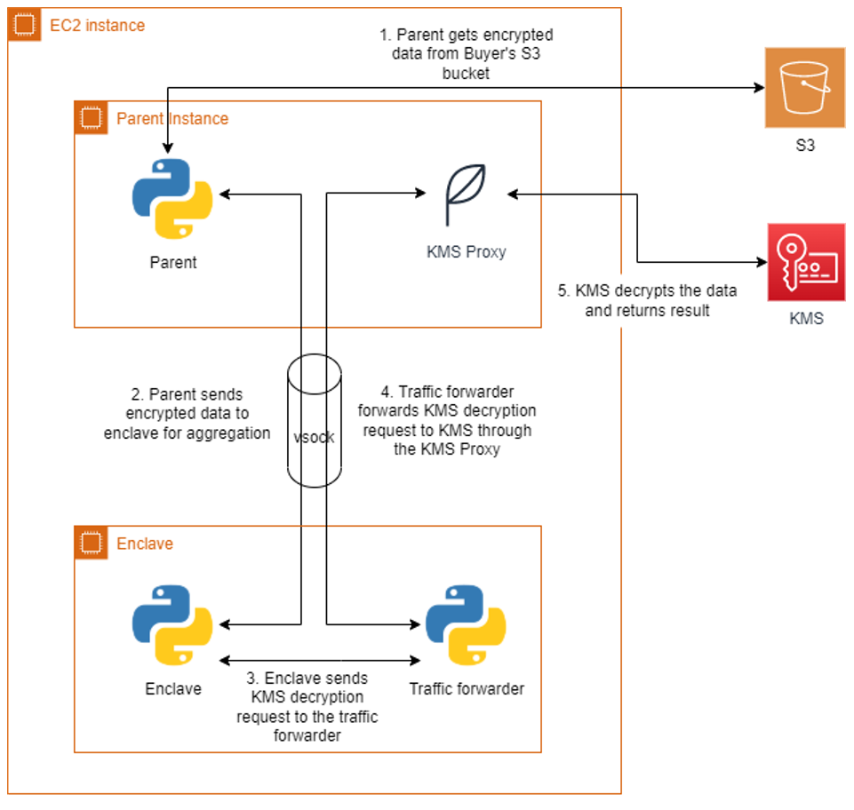
The bidding service will run the enclave image generated earlier on the parent instance. The application runs as two parts, one part on the parent instance and another in the enclave. Communication between the parent and the enclave is done through a vsock connection. An AWS KMS proxy is also used on the parent to allow communication between the enclave and AWS KMS for decrypting data. The parent application will retrieve the encrypted bids from each buyer’s S3 bucket and send them to the enclave. The enclave will decrypt the data using both buyers’ AWS KMS keys and present attestation documents signed by the Nitro Hypervisor. AWS KMS will validate that the PCR values in the attestation documents match the key policy before performing the decryption. The decryption event will be logged in AWS CloudTrail for auditing purposes. Once the encrypted bids are decrypted, the values are compared, and the winning buyer is recorded in the result. The unencrypted result is then returned to the parent and written to an S3 bucket in the bidding service’s account. A diagram of this process is shown in Figure 2.

Cleanup

Be sure you delete all the resources that were created when following the included Github project:

  • Bidding service EC2 instance EC2 instance IAM role and policy
  • AWS KMS Customer managed keys
  • S3 Buckets for storing encrypted files

Conclusion

In this blog post, we introduced a sample POC utilizing Nitro Enclaves to allow a bidding service to process two parties’ encrypted data without revealing their data to any party. We did this by ensuring access to sensitive data is only allowed from an application running within an enclave. With the straightforward integration of AWS KMS and the attestation process, customers can quickly develop applications on Nitro Enclaves that can enable computing on encrypted datasets from multiple accounts. For more information on AWS Nitro Enclaves, see the official product documentation or the introductory videos on YouTube.

Implementing Attribute-Based Instance Type Selection using Terraform

Post Syndicated from Sheila Busser original https://aws.amazon.com/blogs/compute/implementing-attribute-based-instance-type-selection-using-terraform/

This blog post is written by Christian Melendez, Senior Specialist Solutions Architect, Flexible Compute – EC2 Spot and Carlos Manzanedo Rueda, WW SA Leader, Flexible Compute – EC2 Spot.

In this blog post we will cover the release of Terraform support for Attribute-Based Instance Type Selection (ABS). ABS simplifies the configuration required to acquire compute capacity for Instance Flexible workloads. Terraform  is an open-source infrastructure as code software tool by HashiCorp. Hashicorp is an AWS Partner Network (APN) Advanced Technology Partner and member of the AWS DevOps Competency.

Introduction

Amazon EC2 provides a wide selection of instance types optimized to fit different use cases. Instance types comprise varying combinations of CPU, memory, storage, and networking capacity and give you the flexibility to choose the appropriate mix of resources for your applications.

Workloads such as continuous integration, analytics, microservices on containers, etc., can use multiple instance types. Customers have been telling us that simplifying the configuration of instance flexible workloads is important. For workloads that are instance flexible, AWS released ABS to express workload requirements as a set of instance attributes such as: vCPU, memory, type of processor, etc. ABS translates these requirements and selects all matching instance types that meet the criteria. To select which instance to launch, Amazon EC2 Auto Scaling Groups and EC2 Fleet chose instances based on the allocation strategy configured. Lowest-price allocation strategy is supported on both Amazon EC2 On-Demand Instances and Amazon EC2 Spot Instances. The recommendation for Spot Instances is to use capacity-optimized, which select the optimal instances that reduce the frequency of interruptions. ABS does also future-proof EC2 Auto Scaling Group and EC2 Fleet configurations: any new instance type we launch that matches the selected attributes, will be included in the list automatically. No need to update your EC2 Auto Scaling Group or EC2 Fleet configuration.

Following our commitment to open-source projects, AWS has added support for ABS in the AWS Terraform provider. You can use ABS for launch templates, EC2 Auto Scaling Group, and EC2 Fleet resources. The minimum required version of the AWS provider is v4.16.0.

Applying instance flexibility is key for running fault-tolerant, elastic, reliable, and cost optimized workloads. By selecting a diversified choice of instances that qualify for your workload, your application will be better prepared to avoid scenarios where lack of capacity on a specific instance type could be an issue. This applies both to On-Demand and Spot Instance-based workloads. For Spot Instances, applying diversification is key. Spot Instances are spare capacity that can be reclaimed by EC2 when it is required. ABS allows you to specify diversification in simple terms, allowing EC2 Auto Scaling Group and EC2 Fleet’s allocation strategy to replace reclaimed Spot Instances with instances from other pools where capacity is available.

Instance Requirement Attributes

To represent the instance requirements for your workload using ABS, there are a set of attributes you can use within the instance_requirements block. When using Terraform, the only two required attributes are memory_mib and vcpu_count. The rest of the attributes provide default values that adhere to Instance Flexible workloads best practices. For example, bare_metal attribute is by default excluded. You can see the full list of ABS attributes in the Terraform docs site.

Once ABS attributes are configured, ABS picks a list of instance types that match the criteria. This list is especially important when you’re using Spot Instances. One of Spot Instances best practices is to diversify the instance types which, in combination with the capacity-optimized allocation strategy, gives you access to the highest amount of Spot capacity pools. For On-Demand Instances, the instance types list is important as well. There might be scenarios where On-Demand Instance pools lack capacity. By applying instance flexibility using ABS, you can avoid the InsufficientInstanceCapacity error. And in combination with the lowest-price allocation strategy, you get the lowest price instance types from your diversified selection.

There are different places where we can specify ABS attributes. We can specify them at the launch templates level and declare a base mechanism to select instances. In most cases, the recommendation is to configure ABS attributes at the EC2 Auto Scaling Group and EC2 Fleet level. Let’s explore each of these options.

Configuring instance requirements within launch templates

Launch templates are instance configuration templates where you specify parameters like AMI ID, instance type, key pair, and security groups to launch instances. You can use ABS attributes in a launch template when you need to be prescriptive, and define sane defaults or guardrails for your workloads. This way, EC2 Auto Scaling Group or EC2 Fleet simply reference and use the launch template.

You should use ABS attributes in launch templates when you want to prevent users from overriding the resources specified by a launch template. Note that is still possible to override those requirements.

Let’s say that we have a Java application that requires a minimum of 4 vCPUs and 8 GiB of memory, and has been using the c5.xlarge instance type. After performance testing we’ve identified that runs better with current instance types generations. The following code snippet represents how to define these requirements in a Launch Template. To see the full list of attributes, visit the launch template doc site.

resource "aws_launch_template" "abs" {
  name_prefix = "abs"
  image_id    = data.aws_ami.abs.id

  instance_requirements {
    memory_mib {
      min = 8192
    }
    vcpu_count {
      min = 4
    }
    instance_generations = ["current"]
  }
}

Note by using instance_requirements block in a LaunchTemplate, you’ll need to use the mixed_instances_policy block in the EC2 Auto Scaling Group.

resource "aws_autoscaling_group" "on_demand" {
  availability_zones = ["us-east-1a", "us-east-1b", "us-east-1c"]
  max_size           = 1
  min_size           = 1
  mixed_instances_policy {
    launch_template {
      launch_template_specification {
        launch_template_id = aws_launch_template.abs.id
      }
    }
  }
}

The EC2 Auto Scaling Group will use instance types that match the requirements in the launch template.

You can preview what are the instances that the EC2 Auto Scaling Group will select. The section “How to Preview Matching Instances without Launching Them” of the ABS blog post, describes how to preview the instances that will be selected.

Launching EC2 Spot Instances with EC2 Auto Scaling

Launch templates are very powerful. They allow you to decouple the attributes such as user_data from the actual instance management. They are idempotent and can be versioned which is key for rolling out changes in the configuration and applying EC2 Auto Scaling Group Instance Refresh.

Our recommendation is to define ABS attributes as overrides within the mixed_instances_policy block in EC2 Auto Scaling Groups. For most of the applications, we recommend using EC2 Auto Scaling Group to provision EC2 instances.

Let’s get back to our previous example. Now we want to be more prescriptive for the instance requirements our Java application uses.

Let’s assume that the Java application is memory intensive, requires a vCPU to Memory ratio of 4GB for every vCPU, and has been using the m5.large instance type. Additionally, it does not need hardware accelerators like GPUs, FPGAs, etc. Our application does also require a minimum of 2 vCPUs, and the range of memory has been reduced to 32GB to avoid large garbage collection scenarios. This time, we’d like to launch only Spot Instances. As mentioned earlier in this blog post, diversification is key for Spot. To improve the experience with Spot, let’s enable the capacity rebalance feature from the EC2 Auto Scaling Group to proactively replace instances that are at an elevated risk of being interrupted. The following code snippet represents the ABS attributes we need for the more prescriptive workload:

resource “aws_autoscaling_group” “spot” {
  availability_zones = [“us-east-1a”, “us-east-1b”, “us-east-1c”]
  desired_capacity   = 1
  max_size           = 1
  min_size           = 1
  capacity_rebalance = true

  mixed_instances_policy {
    instances_distribution {
      spot_allocation_strategy = "capacity-optimized"
    }

    launch_template {
      launch_template_specification {
        launch_template_id = aws_launch_template.x86.id
      }

      override {
        instance_requirements {
          memory_mib {
            min = 4096
            max = 32768
          }

          vcpu_count {
            min = 2
          }

          memory_gib_per_vcpu {
            min = 4
            max = 4
          }

          accelerator_count {
            max = 0
          }
        }
      }
    }
  }
}

Launching EC2 Spot Instances with EC2 Fleet

Another method we have to launch EC2 instances is the EC2 Fleet API. We recommend to use EC2 Fleet for workloads that need granular controls to provision capacity. For example, tight HPC workloads where instances must be close together (single Availability Zone and within the same placement group) and need similar instance types. EC2 Fleet is also used by capacity orchestrators such as Karpenter or Atlassian Escalator that implement tuned up and optimized logic to provision capacity.

Let’s say that this time the workload is a CPU bound workload and has been using the c5.9xlarge instance type. The workload can be retried and the application supports checkpointing, so it qualifies to use Spot Instances. Given we’ll be using Spot Instances, we would like to benefit from the capacity rebalance feature as we did before in the EC2 Auto Scaling Group example. The application requires very prescriptive ranges of vCPU and memory and we also need a minimum of 100 GB SSD local storage. While in most cases EC2 Auto Scaling Groups are appropriate solution to procure and maintain capacity, in this case we will use EC2 Fleet.

The following code snippet represents the ABS attributes we need for this workload:

resource "aws_ec2_fleet" "spot" {
  target_capacity_specification {
    default_target_capacity_type = "spot"
    total_target_capacity        = 5
  }

  spot_options {
    allocation_strategy = "capacity-optimized"
    maintenance_strategies {
      capacity_rebalance {
        replacement_strategy = "launch"
      }
    }
  }

  launch_template_config {
    launch_template_specification {
      launch_template_id = aws_launch_template.x86.id
      version            = aws_launch_template.x86.latest_version
    }

    override {
      instance_requirements {
        memory_mib {
          min = 65536
          max = 73728
        }

        vcpu_count {
          min = 32
          max = 36
        }

        cpu_manufacturers   = ["intel"]
        local_storage       = "required"
        local_storage_types = ["ssd"]

        total_local_storage_gb {
          min = 100
        }
      }
    }
  }
}

Multi-Architecture workloads using Graviton and x86 with EC2 Auto Scaling Groups

Another recent feature from EC2 Auto Scaling Groups is that you can build multi-architecture workloads. EC2 Auto Scaling Group allows you to mix Graviton and x86 instance types in the same EC2 Auto Scaling Group. Unlike the x86_64 instances we have used so far, AWS Graviton processors are custom built by AWS using 64-bit Arm. You need to use different launch templates as each architecture needs to use a different AMI. This can be defined in within the override block.

In the example below, we use ABS to define different attributes depending on the CPU architecture. And what’s great about doing this is that we don’t need to exclude instance types. Instances will be launched with a compatible CPU architecture based on the AMI that you specify in our launch template.

Besides supporting mixing architectures, EC2 Auto Scaling Groups allows to combine purchase models. For our example, this time we’ll use a more complex scenario to showcase how powerful and feature rich EC2 Auto Scaling Group has become. The following code snippet applies many of the configurations we’ve seen before, but the key difference here is that we have two overrides. One is for Graviton instances, and another one for x86 instances.

resource "aws_autoscaling_group" "on_demand_spot" {
  availability_zones = ["us-east-1a", "us-east-1b", "us-east-1c"]
  desired_capacity   = 4
  max_size           = 10
  min_size           = 2
  capacity_rebalance = true

  mixed_instances_policy {
    instances_distribution {
      on_demand_base_capacity                  = 2
      on_demand_percentage_above_base_capacity = 0
      spot_allocation_strategy                 = "capacity-optimized"
    }

    launch_template {
      launch_template_specification {
        launch_template_id = aws_launch_template.arm.id
      }

      override {
        launch_template_specification {
          launch_template_id = aws_launch_template.arm.id
        }

        instance_requirements {
          memory_mib {
            min = 16384
            max = 16384
          }

          vcpu_count {
            max = 4
          }
        }
      }

      override {
        launch_template_specification {
          launch_template_id = aws_launch_template.x86.id
        }

        instance_requirements {
          memory_mib {
            min = 16384
          }

          vcpu_count {
            min = 4
          }
        }
      }
    }
  }
}

Multi-architecture workloads can also be applied to container orchestration. Thanks to the Amazon Elastic Container Registry (Ama­zon ECR) support for multi-architecture container images, you can use manifests to push both container images, and Amazon ECR will pull the proper image based on the CPU architecture. We have a workshop for Elastic Kubernetes Service (Amazon EKS) where you can learn more about how to deploy a multi-architecture workload in Amazon EKS.

Conclusion

In this post you’ve learned how to configure ABS to launch instances using Auto Scaling Groups and EC2 Fleet. You’ve learned and how to mix CPU architectures along with purchase models in the same EC2 Auto Scaling Group using Terraform while simplifying the configuration.

Our commitment with open-source projects such as Terraform is to help customers implement AWS best practices in a larger ecosystem easily. ABS support allows customers to get access to compute capacity by simply specifying the resource requirement attributes of their workloads rather than the instance names.

ABS simplifies the configuration for instance flexible workloads and removes the need to list the instances that qualify for your workload. Instead, it simplifies the configuration and future proof for scenarios where AWS includes new instances that qualify for the workload. For Spot workloads where instance diversification is key, ABS simplifies the selection of instances and helps to increase the total number of pools. For more information, visit the ABS user guide and Terraform documentation for Auto Scaling Groups and EC2 Fleet.

Running AWS Lambda functions on AWS Outposts using AWS IoT Greengrass

Post Syndicated from Sheila Busser original https://aws.amazon.com/blogs/compute/running-aws-lambda-functions-on-aws-outposts-using-aws-iot-greengrass/

This blog post is written by Adam Imeson, Sr. Hybrid Edge Specialist Solution Architect.

Today, AWS customers can deploy serverless applications in AWS Regions using a variety of AWS services. Customers can also use AWS Outposts to deploy fully managed AWS infrastructure at virtually any datacenter, colocation space, or on-premises facility.

AWS Outposts extends the cloud by bringing AWS services to customers’ premises to support their hybrid and edge workloads. This post will describe how to deploy Lambda functions on an Outpost using AWS IoT Greengrass.

Consider a customer who has built an application that runs in an AWS Region and depends on AWS Lambda. This customer has a business need to enter a new geographic market, but the nearest AWS Region is not close enough to meet application latency or data residency requirements. AWS Outposts can help this customer extend AWS infrastructure and services to their desired geographic region. This blog post will explain how a customer can move their Lambda-dependent application to an Outpost.

Overview

In this walkthrough you will create a Lambda function that can run on AWS IoT Greengrass and deploy it on an Outpost. This architecture results in an AWS-native Lambda function running on the Outpost.

Architecture overview - Lambda functions on AWS Outposts

Deploying Lambda functions on Outposts rack

Prerequisites: Building a VPC

To get started, build a VPC in the same Region as your Outpost. You can do this with the create VPC option in the AWS console. The workflow allows you to set up a VPC with public and private subnets, an internet gateway, and NAT gateways as necessary. Do not consume all of the available IP space in the VPC with your subnets in this step, because you will still need to create Outposts subnets after this.

Now, build a subnet on your Outpost. You can do this by selecting your Outpost in the Outposts console and choosing Create Subnet in the drop-down Actions menu in the top right.

Confirm subnet details

Choose the VPC you just created and select a CIDR range for your new subnet that doesn’t overlap with the other subnets that are already in the VPC. Once you’ve created the subnet, you need to create a new subnet route table and associate it with your new subnet. Go into the subnet route tables section of the VPC console and create a new route table. Associate the route table with your new subnet. Add a 0.0.0.0/0 route pointing at your VPC’s internet gateway. This sets the subnet up as a public subnet, which for the purposes of this post will make it easier to access the instance you are about to build for Greengrass Core. Depending on your requirements, it may make more sense to set up a private subnet on your Outpost instead. You can also add a route pointing at your Outpost’s local gateway here. Although you won’t be using the local gateway during this walkthrough, adding a route to the local gateway makes it possible to trigger your Outpost-hosted Lambda function with on-premises traffic.

Create a new route table

Associate the route table with the new subnet

Add a 0.0.0.0/0 route pointing at your VPC’s internet gateway

Setup: Launching an instance to run Greengrass Core

Create a new EC2 instance in your Outpost subnet. As long as your Outpost has capacity for your desired instance type, this operation will proceed the same way as any other EC2 instance launch. You can check your Outpost’s capacity in the Outposts console or in Amazon CloudWatch:

I used a c5.large instance running Amazon Linux 2 with 20 GiB of Amazon EBS storage for this walkthough. You can pick a different instance size or a different operating system in accordance with your application’s needs and the AWS IoT Greengrass documentation. For the purposes of this tutorial, we assign a public IP address to the EC2 instance on creation.

Step 1: Installing the AWS IoT Greengrass Core software

Once your EC2 instance is up and running, you will need to install the AWS IoT Greengrass Core software on the instance. Follow the AWS IoT Greengrass documentation to do this. You will need to do the following:

  1. Ensure that your EC2 instance has appropriate AWS permissions to make AWS API calls. You can do this by attaching an instance profile to the instance, or by providing AWS credentials directly to the instance as environment variables, as in the Greengrass documentation.
  2. Log in to your instance.
  3. Install OpenJDK 11. For Amazon Linux 2, you can use sudo amazon-linux-extras install java-openjdk11 to do this.
  4. Create the default system user and group that runs components on the device, with
    sudo useradd —system —create-home ggc_user
    sudo groupadd —system ggc_group
  5. Edit the /etc/sudoers file with sudo visudosuch that the entry for the root user looks like root ALL=(ALL:ALL) ALL
  6. Enable cgroups and enable and mount the memory and devices cgroups. In Amazon Linux 2, you can do this with the grubby utility as follows:
    sudo grubby --args="cgroup_enable=memory cgroup_memory=1 systemd.unified_cgroup_hierarchy=0" --update-kernel /boot/vmlinuz-$(uname -r)
  7. Type sudo reboot to reboot your instance with the cgroup boot parameters enabled.
  8. Log back in to your instance once it has rebooted.
  9. Use this command to download the AWS IoT Greengrass Core software to the instance:
    curl -s https://d2s8p88vqu9w66.cloudfront.net/releases/greengrass-nucleus-latest.zip > greengrass-nucleus-latest.zip
  10. Unzip the AWS IoT Greengrass Core software:
    unzip greengrass-nucleus-latest.zip -d GreengrassInstaller && rm greengrass-nucleus-latest.zip
  11. Run the following command to launch the installer. Replace each argument with appropriate values for your particular deployment, particularly the aws-region and thing-name arguments.
    sudo -E java -Droot="/greengrass/v2" -Dlog.store=FILE \
    -jar ./GreengrassInstaller/lib/Greengrass.jar \
    --aws-region region \
    --thing-name MyGreengrassCore \
    --thing-group-name MyGreengrassCoreGroup \
    --thing-policy-name GreengrassV2IoTThingPolicy \
    --tes-role-name GreengrassV2TokenExchangeRole \
    --tes-role-alias-name GreengrassCoreTokenExchangeRoleAlias \
    --component-default-user ggc_user:ggc_group \
    --provision true \
    --setup-system-service true \
    --deploy-dev-tools true
  12. You have now installed the AWS IoT Greengrass Core software on your EC2 instance. If you type sudo systemctl status greengrass.service then you should see output similar to this:

Step 2: Building and deploying a Lambda function

Now build a Lambda function and deploy it to the new Greengrass Core instance. You can find example local Lambda functions in the aws-greengrass-lambda-functions GitHub repository. This example will use the Hello World Python 3 function from that repo.

  1. Create the Lambda function. Go to the Lambda console, choose Create function, and select the Python 3.8 runtime:

  1. Choose Create function at the bottom of the page. Once your new function has been created, copy the code from the Hello World Python 3 example into your function:

  1. Choose Deploy to deploy your new function’s code.
  2. In the top right, choose Actions and select Publish new version. For this particular function, you would need to create a deployment package with the AWS IoT Greengrass SDK for the function to work on the device. I’ve omitted this step for brevity as it is not a main focus of this post. Please reference the Lambda documentation on deployment packages and the Python-specific deployment package docs if you want to pursue this option.

  1. Go to the AWS IoT Greengrass console and choose Components in the left-side pop-in menu.
  2. On the Components page, choose Create component, and then Import Lambda function. If you prefer to do this programmatically, see the relevant AWS IoT Greengrass documentation or AWS CloudFormation documentation.
  3. Choose your new Lambda function from the drop-down.

Create component

  1. Scroll to the bottom and choose Create component.
  2. Go to the Core devices menu in the left-side nav bar and select your Greengrass Core device. This is the Greengrass Core EC2 instance you set up earlier. Make a note of the core device’s name.

  1. Use the left-side nav bar to go to the Deployments menu. Choose Create to create a new deployment, which will place your Lambda function on your Outpost-hosted core device.
  2. Give the deployment a name and select Core device, providing the name of your core device. Choose Next.

  1. Select your Lambda function and choose Next.

  1. Choose Next again, on both the Configure components and Configure advanced settings On the last page, choose Deploy.

You should see a green message at the top of the screen indicating that your configuration is now being deployed.

Clean up

  1. Delete the Lambda function you created.
  2. Terminate the Greengrass Core EC2 instance.
  3. Delete the VPC.

Conclusion

Many customers use AWS Outposts to expand applications into new geographies. Some customers want to run Lambda-based applications on Outposts. This blog post shows how to use AWS IoT Greengrass to build Lambda functions which run locally on Outposts.

To learn more about Outposts, please contact your AWS representative and visit the Outposts homepage and documentation.

Making your Go workloads up to 20% faster with Go 1.18 and AWS Graviton

Post Syndicated from Sheila Busser original https://aws.amazon.com/blogs/compute/making-your-go-workloads-up-to-20-faster-with-go-1-18-and-aws-graviton/

This blog post was written by Syl Taylor, Professional Services Consultant.

In March 2022, the highly anticipated Go 1.18 was released. Go 1.18 brings to the language some long-awaited features and additions, such as generics. It also brings significant performance improvements for Arm’s 64-bit architecture used in AWS Graviton server processors. In this post, we show how migrating Go workloads from Go 1.17.8 to Go 1.18 can help you run your applications up to 20% faster and more cost-effectively. To achieve this goal, we selected a series of realistic and relatable workloads to showcase how they perform when compiled with Go 1.18.

Overview

Go is an open-source programming language which can be used to create a wide range of applications. It’s developer-friendly and suitable for designing production-grade workloads in areas such as web development, distributed systems, and cloud-native software.

AWS Graviton2 processors are custom-built by AWS using 64-bit Arm Neoverse cores to deliver the best price-performance for your cloud workloads running in Amazon Elastic Compute Cloud (Amazon EC2). They provide up to 40% better price/performance over comparable x86-based instances for a wide variety of workloads and they can run numerous applications, including those written in Go.

Web service throughput

For web applications, the number of HTTP requests that a server can process in a window of time is an important measurement to determine scalability needs and reduce costs.

To demonstrate the performance improvements for a Go-based web service, we selected the popular Caddy web server. To perform the load testing, we selected the hey application, which was also written in Go. We deployed these packages in a client/server scenario on m6g Graviton instances.

Relative performance comparison for requesting a static webpage

The Caddy web server compiled with Go 1.18 brings a 7-8% throughput improvement as compared with the variant compiled with Go 1.17.8.

We conducted a second test where the client downloads a dynamic page on which the request handler performs some additional processing to write the HTTP response content. The performance gains were also noticeable at 10-11%.

Relative performance comparison for requesting a dynamic webpage

Regular expression searches

Searching through large amounts of text is where regular expression patterns excel. They can be used for many use cases, such as:

  • Checking if a string has a valid format (e.g., email address, domain name, IP address),
  • Finding all of the occurrences of a string (e.g., date) in a text document,
  • Identifying a string and replacing it with another.

However, despite their efficiency in search engines, text editors, or log parsers, regular expression evaluation is an expensive operation to run. We recommend identifying optimizations to reduce search time and compute costs.

The following example uses the Go regexp package to compile a pattern and search for the presence of a standard date format in a large generated string. We observed a 13.5% increase in completed executions with a 12% reduction in execution time.

Relative performance comparison for using regular expressions to check that a pattern exists

In a second example, we used the Go regexp package to find all of the occurrences of a pattern for character sequences in a string, and then replace them with a single character. We observed a 12% increase in evaluation rate with an 11% reduction in execution time.

Relative performance comparison for using regular expressions to find and replace all of the occurrences of a pattern

As with most workloads, the improvements will vary depending on the input data, the hardware selected, and the software stack installed. Furthermore, with this use case, the regular expression usage will have an impact on the overall performance. Given the importance of regex patterns in modern applications, as well as the scale at which they’re used, we recommend upgrading to Go 1.18 for any software that relies heavily on regular expression operations.

Database storage engines

Many database storage engines use a key-value store design to benefit from simplicity of use, faster speed, and improved horizontal scalability. Two implementations commonly used are B-trees and LSM (log-structured merge) trees. In the age of cloud technology, building distributed applications that leverage a suitable database service is important to make sure that you maximize your business outcomes.

B-trees are seen in many database management systems (DBMS), and they’re used to efficiently perform queries using indexes. When we tested a sample program for inserting and deleting in a large B-tree structure, we observed a 10.5% throughput increase with a 10% reduction in execution time.

Relative performance comparison for inserting and deleting in a B-Tree structure

On the other hand, LSM trees can achieve high rates of write throughput, thus making them useful for big data or time series events, such as metrics and real-time analytics. They’re used in modern applications due to their ability to handle large write workloads in a time of rapid data growth. The following are examples of databases that use LSM trees:

  • InfluxDB is a powerful database used for high-speed read and writes on time series data. It’s written in Go and its storage engine uses a variation of LSM called the Time-Structured Merge Tree (TSM).
  • CockroachDB is a popular distributed SQL database written in Go with its own LSM tree implementation.
  • Badger is written in Go and is the engine behind Dgraph, a graph database. Its design leverages LSM trees.

When we tested an LSM tree sample program, we observed a 13.5% throughput increase with a 9.5% reduction in execution time.

We also tested InfluxDB using comparison benchmarks to analyze writes and reads to the database server. On the load stress test, we saw a 10% increase of insertion throughput and a 14.5% faster rate when querying at a large scale.

Relative performance comparison for inserting to and querying from an InfluxDB database

In summary, for databases with an engine written in Go, you’ll likely observe better performance when upgrading to a version that has been compiled with Go 1.18.

Machine learning training

A popular unsupervised machine learning (ML) algorithm is K-Means clustering. It aims to group similar data points into k clusters. We used a dataset of 2D coordinates to train K-Means and obtain the cluster distribution in a deterministic manner. The example program uses an OOP design. We noticed an 18% improvement in execution throughput and a 15% reduction in execution time.

Relative performance comparison for training a K-means model

A widely-used and supervised ML algorithm for both classification and regression is Random Forest. It’s composed of numerous individual decision trees, and it uses a voting mechanism to determine which prediction to use. It’s a powerful method for optimizing ML models.

We ran a deterministic example to train a dense Random Forest. The program uses an OOP design and we noted a 20% improvement in execution throughput and a 15% reduction in execution time.

Relative performance comparison for training a Random Forest model

Recursion

An efficient, general-purpose method for sorting data is the merge sort algorithm. It works by repeatedly breaking down the data into parts until it can compare single units to each other. Then, it decides their order in the intermediary steps that will merge repeatedly until the final sorted result. To implement this divide-and-conquer approach, merge sort must use recursion. We ran the program using a large dataset of numbers and observed a 7% improvement in execution throughput and a 4.5% reduction in execution time.

Relative performance comparison for running a merge sort algorithm

Depth-first search (DFS) is a fundamental recursive algorithm for traversing tree or graph data structures. Many complex applications rely on DFS variants to solve or optimize hard problems in various areas, such as path finding, scheduling, or circuit design. We implemented a standard DFS traversal in a fully-connected graph. Then we observed a 14.5% improvement in execution throughput and a 13% reduction in execution time.

Relative performance comparison for running a DFS algorithm

Conclusion

In this post, we’ve shown that a variety of applications, not just those primarily compute-bound, can benefit from the 64-bit Arm CPU performance improvements released in Go 1.18. Programs with an object-oriented design, recursion, or that have many function calls in their implementation will likely benefit more from the new register ABI calling convention.

By using AWS Graviton EC2 instances, you can benefit from up to a 40% price/performance improvement over other instance types. Furthermore, you can save even more with Graviton through the additional performance improvements by simply recompiling your Go applications with Go 1.18.

To learn more about Graviton, see the Getting started with AWS Graviton guide.

New AWS Wavelength Zone in Toronto – The First in Canada

Post Syndicated from Danilo Poccia original https://aws.amazon.com/blogs/aws/new-aws-wavelength-zone-in-toronto-the-first-in-canada/

Wireless communication has put us closer to each other. 5G networks increase the reach of what we can achieve to new use cases that need end-to-end low latency. With AWS Wavelength, you can deploy AWS compute and storage services within telecommunications providers’ data centers at the edge of the 5G networks. Your applications can then deliver single-digit millisecond latencies to mobile devices and end users and, at the same time, seamlessly access AWS services in the closest AWS Region.

For example, low latency enables new use cases such as:

  • Delivery of high-resolution and high-fidelity live video streaming.
  • Improved experience for augmented/virtual reality (AR/VR) applications.
  • Running machine learning (ML) inference at the edge for applications in medical diagnostics, retail, and factories.
  • Connected vehicle applications with near real-time connectivity with the cloud to improve driver assistance, autonomous driving, and in-vehicle entertainment experiences.

We opened the first AWS Wavelength Zones in 2020 in the US, and then we expanded to new countries, such as Japan, South Korea, the United Kingdom, and Germany. Today, I am happy to share that, in partnership with Bell Canada, we are expanding in a new country with a Wavelength Zone in Toronto.

What You Can Do with AWS Wavelength
As an example of what is possible with Wavelength, let’s look at food deliveries in Toronto. Most deliveries are made within 2 km, and a significant number are for just one item, such as a cup of coffee. Using a car for these deliveries is slow, expensive, and has a large carbon footprint. A better solution is provided by Tiny Mile: they use small remote-controlled robots to deliver small food orders such as coffees and sandwiches at one-tenth the cost of conventional delivery services.

Tiny Mile robot image.

Their remote staff uses the camera feed from the robots to understand the environment, read signage, and drive the robots. To scale up more efficiently, Tiny Mile can now use Bell’s public Multi-access Edge Computing (MEC) solution, delivered through AWS Wavelength, to process data and analyze the video feed in almost real time to detect obstacles and avoid collisions without manual intervention. Having computation at the edge also reduces the weight and the costs of the robots (they don’t need expensive computers onboard) and increases the amount of cargo they can carry.

Using a Wavelength Zone
I follow the instructions in Get started with AWS Wavelength in the documentation. First, I opt in to use the new Wavelength Zone. In the EC2 console for the Canada (Central) Region, I enable New EC2 Experience in the upper-left corner. In the navigation pane, I choose EC2 Dashboard. In the Account attributes section, I choose Zones. There, I enable the Canada (BELL) Wavelength Zone.

Console screenshot.

Now, I can configure networking to use the Wavelength Zone. I can either create an Amazon Virtual Private Cloud (VPC) or extend an existing VPC to include a subnet in a Wavelength Zone. In this case, I want to use a new VPC. In the VPC console, I choose Your VPCs and then Create VPC. I select the VPC only option to create subnets later. I write a name for the VPC and choose the IPv4 CIDR block that will be used for the private addresses of the resources in this VPC. Then, I complete the creation of the VPC.

Console screenshot.

In the navigation pane, I choose Carrier Gateways and then Create carrier gateway. I write a name and select the VPC I just created. I enable Route subnet traffic to the carrier gateway to automatically route traffic from subnets to the carrier gateway.

Console screenshot.

In the Subnets to route section, I configure a subnet residing in the Canada (BELL) – Toronto Wavelength Zone. For the subnet IPv4 CIDR Block, I use a block within the VPC range. Then, I complete the creation of the carrier gateway.

Console screenshot.

Now that networking is configured, I can deploy the portions of my application that require ultra-low latency in the Wavelength Zone and then connect that back to the rest of the application and the cloud services running in the Canada (Central) Region.

To run an EC2 instance in the Wavelength Zone, I use the AWS Command Line Interface (CLI) run-instances command. In this way, I can pass an option to automatically allocate and associate the Carrier IP address with the network interface of the EC2 instance. Another option is to allocate the carrier address and associate it with the network interface after I create the instance. The Carrier IP address is only valid within the telecommunications provider’s network. The carrier gateway uses NAT to translate the Carrier IP address and send traffic to the internet or to mobile devices.

aws ec2 --region ca-central-1 run-instances
--network-interfaces '[{"DeviceIndex":0, "AssociateCarrierIpAddress": true, "SubnetId": "subnet-0d753f7203c2cfd42"}]'
--image-id ami-01d29fca5bdf8f4b4 --instance-type t3.medium

To discover the IP associated with the EC2 instance in the carrier network, I use the describe-instances command:

aws ec2 --region ca-central-1 describe-instances

In the NetworkInterfaces section of the output, I find the Association and the CarrierIP:

"Association": {
  "CarrierIp": "207.61.170.56",
  "IpOwnerId": "amazon",
  "PublicDnsName": ""
}

Now that the EC2 instance is running in the Wavelength Zone, I can deploy a portion of my application in the EC2 instance so that application traffic can be processed at very low latency without leaving the mobile network.

Architectural diagram.

For my next steps, I look at Deploying your first 5G enabled application with AWS Wavelength and follow the walkthrough for a common Wavelength use case: implementing machine learning inference at the edge.

Availability and Pricing
The new Wavelength Zone in Toronto, Canada, is embedded in Bell Canada’s 5G network and is available today. EC2 instances and other AWS resources in Wavelength Zones have different prices than in the parent Region. See the Wavelength pricing page for more information.

AWS Wavelength is part of AWS for the Edge services that help you deliver data processing, analysis, and storage outside AWS data centers and closer to your endpoints. These capabilities allow you to process and store data close to where it’s generated, enabling low-latency, intelligent, and real-time responsiveness.

Start using AWS Wavelength to deliver ultra-low-latency applications for 5G devices.

Danilo

Build a custom Java runtime for AWS Lambda

Post Syndicated from Marcia Villalba original https://aws.amazon.com/blogs/compute/build-a-custom-java-runtime-for-aws-lambda/

This post is written by Christian Müller, Principal AWS Solutions Architect and Maximilian Schellhorn, AWS Solutions Architect

When running applications on AWS Lambda, you have the option to use either one of the managed runtime versions that AWS provides or bring your own custom runtime. The following blog post provides a walkthrough of how you can create and optimize a custom runtime for Java based Lambda functions.

Builders might rely on customized or experimental runtime behavior when creating solutions in the cloud. The Java ecosystem fosters innovation and encourages experiments with the current six-month release schedule for the latest runtime versions.

However, Lambda focuses on providing stable long-term support (LTS) versions. The official Lambda runtimes are built around a combination of operating system, programming language, and software libraries that are subject to maintenance and security updates. For example, the Lambda runtime for Java supports the LTS versions Java 8 Corretto and Java 11 Corretto as of April 2022. The Java 17 Corretto version is pending. In addition, there is no provided runtime for non LTS versions like Java 15 Corretto, Java 16 Corretto, or Java 18 Corretto.

To use other language versions, Lambda allows you to create custom runtimes. Custom runtimes allow builders to provide and configure their own runtimes for running their application code. To enable communication between your custom runtime and Lambda, you can use the runtime interface client library in Java.

With the introduction of modular runtime images in Java 9 (JEP 220), it is possible to include only the Java runtime modules that your application depends on. This reduces the overall runtime size and increases performance, especially during cold-starts. In addition, there are other techniques in Java, like class data sharing and tiered compilation, which allow you to reduce the startup time of your application even further.

To combine those capabilities, this blog post provides an overview for creating and deploying a minified Java runtime on Lambda by using Java 18 Corretto. For step-by-step instructions and prerequisites, refer to the official GitHub example.

Overview of the example

In the following example, you build a custom runtime for a basic Java application that writes request headers to Amazon DynamoDB and is fronted by Amazon API Gateway.

Application architecture

The following diagram summarizes the steps to create the application and the custom runtime:

Steps to create the application custom runtime

  1. Download the preferred Java version and take advantage of jdeps, jlink and class data sharing to create a minified and optimized Java runtime based on the application code (function.jar).
  2. Create a bootstrap file with optimized starting instructions for the application.
  3. Package the application code, the optimized Java runtime, and the bootstrap file as a zip file.
  4. Deploy the runtime, including the app, to Lambda. For example, using the AWS Cloud Development Kit (CDK)

Steps 1–3 are automated and abstracted via Docker. The following section provides a high-level walkthrough of the build and deployment process. For the full version, see the Dockerfile in the GitHub example.

Creating the optimized Java runtime

1. Download the desired Java version and copy the local application code to the Docker environment and build it with Maven:

FROM amazonlinux:2

...

# Update packages and install Amazon Corretto 18, Maven and Zip
RUN yum -y update
RUN yum install -y java-18-amazon-corretto-devel maven zip

...

# Copy the software folder to the image and build the function
COPY software software
WORKDIR /software/example-function
RUN mvn clean package

2. This step results in an uber-jar (function.jar) that you can use as an input argument for jdeps. The output is a file containing all the Java modules that the function depends on:

RUN jdeps -q \
    --ignore-missing-deps \
    --multi-release 18 \
    --print-module-deps \
    target/function.jar > jre-deps.info

3. Create an optimized Java runtime based on those application modules with jlink. Remove unnecessary information from the runtime, for example header files or man-pages:

RUN jlink --verbose \
    --compress 2 \
    --strip-java-debug-attributes \
    --no-header-files \
    --no-man-pages \
    --output /jre18-slim \
    --add-modules $(cat jre-deps.info)

4. This creates your own custom Java 18 runtime in the /jre18-slim folder. You can apply additional optimization techniques such as Class-Data-Sharing (CDS) to generate a classes.jsa file to accelerate the class loading time of the JVM.

RUN /jre18-slim/bin/java -Xshare:dump

Adding optimized starting instructions

You must tell the Lambda execution environment how to start the application. You can achieve that with a bootstrap file that includes the necessary instructions. In addition, you can define parameters to improve the performance further. For example, you could use tiered compilation and SerialGC.

The following snippet represents an example of a bootstrap file:

#!/bin/sh

$LAMBDA_TASK_ROOT/jre18-slim/bin/java \
    --add-opens java.base/java.util=ALL-UNNAMED \
    -XX:+TieredCompilation \
    -XX:TieredStopAtLevel=1 \
    -XX:+UseSerialGC \
    -jar function.jar "$_HANDLER"

Packaging the components

Combine the bootstrap file, the custom Java runtime, and the application code in a zip file for later use as the deployment package:

RUN zip -r runtime.zip \
    bootstrap \
    function.jar \
    /jre18-slim

The GitHub example provides a build.sh script to run the above-mentioned process via Docker. This results in a runtime.zip that you can then use as a deployment package.

Deploying the application with the custom runtime

To deploy the custom runtime, use AWS CDK. This allows you to define the needed infrastructure as code more easily in your favorite programming language.

The following code snippet shows how to create a Lambda function from a custom runtime:

Function customJava18Function = new Function(this, "LambdaCustomRuntimeJava18", FunctionProps.builder()
        .functionName("custom-runtime-java-18")
.handler("com.amazon.aws.example.ExampleDynamoDbHandler::handleRequest")
        .runtime(Runtime.PROVIDED_AL2)
        .code(Code.fromAsset("../runtime.zip"))
        .memorySize(512)
        .environment(Map.of("TABLE_NAME", exampleTable.getTableName()))
        .timeout(Duration.seconds(20))
        .logRetention(RetentionDays.ONE_WEEK)
        .build());

To deploy the application and output the necessary API Gateway URL to invoke the Lambda function, use the following command or use the provided provision_infrastructure.sh script:

cdk deploy --outputs-file target/outputs.json

Testing the application and validating the example results

After deployment, you can load test the application with the open-source software project Artillery.

The following command creates 120 concurrent invocations of the Lambda function for a duration of 60 seconds. It uses the API Gateway URL that is exported after the AWS CDK successfully deployed the application:

artillery run -t $(cat infrastructure/target/outputs.json | jq -r '.LambdaCustomRuntimeMinimalJRE18InfrastructureStack.apiendpoint') -v '{ "url": "/custom-runtime" }' infrastructure/loadtest.yml

Use CloudWatch Log Insights to query the Lambda logs and gather information about the cold start (initDuration) and duration percentiles:

filter @type = "REPORT"
    | parse @log /\d+:\/aws\/lambda\/(?<function>.*)/
    | stats
    count(*) as invocations,
    pct(@duration+coalesce(@initDuration,0), 0) as p0,
    pct(@duration+coalesce(@initDuration,0), 25) as p25,
    pct(@duration+coalesce(@initDuration,0), 50) as p50,
    pct(@duration+coalesce(@initDuration,0), 75) as p75,
    pct(@duration+coalesce(@initDuration,0), 90) as p90,
    pct(@duration+coalesce(@initDuration,0), 95) as p95,
    pct(@duration+coalesce(@initDuration,0), 99) as p99,
    pct(@duration+coalesce(@initDuration,0), 100) as p100
    group by function, ispresent(@initDuration) as coldstart
    | sort by coldstart, function

The results provide an indication of how your application performs with the custom runtime. This is especially helpful when comparing different versions.

  • Invocation time (@duration) for both cold and warm starts plus function initialization time (@initDuration) if it is a cold start:

Invocation time

  • Function initialization time (@initDuration) only:

Function initialisation time

Conclusion

In this blog post, you learn how to create your own optimized Java runtime for AWS Lambda by using a variety of Java optimization techniques. This allows you to tailor your Java runtime to your application needs.

See the full example on GitHub and make use of your own preferred Java version. Add additional optimization steps in the Dockerfile or tune the parameters in the bootstrap file to optimize the start of the Java virtual machine.

In case you want to re-use your custom runtime in multiple Lambda functions, you can also distribute it via a Lambda layer.

For more serverless learning resources, visit Serverless Land.

Announcing AWS Lambda Function URLs: Built-in HTTPS Endpoints for Single-Function Microservices

Post Syndicated from Alex Casalboni original https://aws.amazon.com/blogs/aws/announcing-aws-lambda-function-urls-built-in-https-endpoints-for-single-function-microservices/

Organizations are adopting microservices architectures to build resilient and scalable applications using AWS Lambda. These applications are composed of multiple serverless functions that implement the business logic. Each function is mapped to API endpoints, methods, and resources using services such as Amazon API Gateway and Application Load Balancer.

But sometimes all you need is a simple way to configure an HTTPS endpoint in front of your function without having to learn, configure, and operate additional services besides Lambda. For example, you might need to implement a webhook handler or a simple form validator that runs within an individual Lambda function.

Today, I’m happy to announce the general availability of Lambda Function URLs, a new feature that lets you add HTTPS endpoints to any Lambda function and optionally configure Cross-Origin Resource Sharing (CORS) headers.

This lets you focus on what matters while we take care of configuring and monitoring a highly available, scalable, and secure HTTPS service.

How Lambda Function URLs Work
Create a new function URL and map it to any function. Each function URL is globally unique and can be associated with a function’s alias or the function’s unqualified ARN, which implicitly invokes the $LATEST version.

For example, if you map a function URL to your $LATEST version, each code update will be available immediately via the function URL. On the other hand, I’d recommend mapping a function URL to an alias, so you can safely deploy new versions, perform some integration tests, and then update the alias when you’re ready. This also lets you implement weighted traffic shifting and safe deployments.

Function URLs are natively supported by the Lambda API, and you can start using it via the AWS Management Console or AWS SDKs, as well as infrastructure as code(IaC) tools such as AWS CloudFormation, AWS SAM, or AWS Cloud Development Kit (AWS CDK).

Lambda Function URLs in Action
You can configure a function URL for a new or an existing function. Let’s see how to implement a new function to handle a webhook.

When creating a new function, I check Enable function URL in Advanced Settings.

Here, I select Auth type: AWS_IAM or NONE. My webhook will use custom authorization logic based on a signature provided in the HTTP headers. Therefore, I’ll choose AuthType None, which means Lambda won’t check for any AWS IAM Sigv4 signatures before invoking my function. Instead, I’ll extract and validate a custom header in my function handler for authorization.

AWS Lambda URLs - Create Function

Please note that when using AuthType None, my function’s resource-based policy must still explicitly allow for public access. Otherwise, unauthenticated requests will be rejected. You can add permissions programmatically using the AddPermission API. In this case, the Lambda console automatically adds the necessary policy for me, as the IAM role I’m using is authorized to call the AddPermission API in my account.

With one click, I can also enable CORS. The default CORS configuration will allow all origins. Then, I’ll add more granular controls after creating the function. In case you’re not familiar with CORS, it’s a header-based security mechanism implemented by browsers to make sure that only certain hosts are allowed to load resources and invoke APIs. If a website is allowed to consume your API, you’ll need to include a few CORS headers that declare which origins, methods, and custom headers are allowed. The new function URLs take care of it for you, so you don’t have to implement all of this in your Lambda handler.

A few seconds later, the function URL is available. I can also easily find and copy it in the Lambda console.

AWS Lambda URLs - Console URL

The function code that handles my webhook in Node.js looks like this:

exports.handler = async (event) => {
    
    // (optional) fetch method and querystring
    const method = event.requestContext.http.method;
    const queryParam = event.queryStringParameters.myCustomParameter;
    console.log(`Received ${method} request with ${queryParam}`)
    
    // retrieve signature and payload
    const webhookSignature = event.headers.SignatureHeader;
    const webhookPayload = JSON.parse(event.body);
    
    try {
        validateSignature(webhookSignature); // throws if invalid signature
        handleEvent(webhookPayload); // throws if processing error
    } catch (error) {
        console.error(error)
        return {
            statusCode: 400,
            body: `Cannot process event: ${error}`,
        }
    }

    return {
        statusCode: 200, // default value
        body: JSON.stringify({
            received: true,
        }),
    };
};

The code is extracting a few parameters from the request headers, query string, and body. If you’re already familiar with the event structure provided by API Gateway or Application Load Balancer, this should look very familiar.

After updating the code, I decide to test the function URL with an HTTP client.

For example, here’s how I’d do it with curl:

$ curl "https://4iykoi7jk2kp5hhd5irhbdprn40yxest.lambda-url.us-west-2.on.aws/?myCustomParameter=squirrel"
    -X POST
    -H "SignatureHeader: XYZ"
    -H "Content-type: application/json"
    -d '{"type": "payment-succeeded"}'

Or with a Python script:

import json
import requests

url = "https://4iykoi7jk2kp5hhd5irhbdprn40yxest.lambda-url.us-west-2.on.aws/"
headers = {'SignatureHeader': 'XYZ', 'Content-type': 'application/json'}
payload = json.dumps({'type': 'payment-succeeded'})
querystring = {'myCustomParameter': 'squirrel'}

r = requests.post(url=url, params=querystring, data=payload, headers=headers)
print(r.json())

Don’t forget to set the request’s Content-type to application/json or text/* in your tests, otherwise, the body will be base64-encoded by default, and you’ll need to decode it in the Lambda handler.

Of course, in this case we’re talking about a webhook, so this function will receive requests directly from the external system that I’m integrating with. I only need to provide them with the public function URL and start receiving events.

For this specific use case, I don’t need any CORS configuration. In other cases where the function URL is called from the browser, I’d need to configure a few more CORS parameters such as Access-Control-Allow-Origin, Access-Control-Allow-Methods, and Access-Control-Expose-Headers. I can easily review and edit these CORS parameters in the Lambda console or in my IaC templates. Here’s what it looks like in the console:

AWS Lambda URLs - CORS

Also, keep in mind that each function URL is unique and mapped to a specific alias or the $LATEST version of your function. This lets you define multiple URLs for the same function. For example, you can define one for testing the $LATEST version during development and one for each stage or alias, such as staging, production, and so on.

Support for Infrastructure as Code (IaC)
You can start configuring Lambda Function URLs directly in your IaC templates today using AWS CloudFormation, AWS SAM, and AWS Cloud Development Kit (AWS CDK).

For example, here’s how to define a Lambda function and its public URL with AWS SAM, including the alias mapping:

WebhookFunction:
    Type: AWS::Serverless::Function
    Properties:
      CodeUri: webhook/
      Handler: index.handler
      Runtime: nodejs14.x
      AutoPublishAlias: live
      FunctionUrlConfig:
        AuthType: NONE
        Cors:
            AllowOrigins:
                - "https://example.com"

If you have existing Lambda functions in your IaC templates, you can define a new function URL with a few lines of code.

Function URL Pricing
Function URLs are included in Lambda’s request and duration pricing. For example, let’s imagine that you deploy a single Lambda function with 128 MB of memory and an average invocation time of 50 ms. The function receives five million requests every month, so the cost will be $1.00 for the requests, and $0.53 for the duration. The grand total is $1.53 per month, in the US East (N. Virginia) Region.

When to use Function URLs vs. Amazon API Gateway
Function URLs are best for use cases where you must implement a single-function microservice with a public endpoint that doesn’t require the advanced functionality of API Gateway, such as request validation, throttling, custom authorizers, custom domain names, usage plans, or caching. For example, when you are implementing webhook handlers, form validators, mobile payment processing, advertisement placement, machine learning inference, and so on. It is also the simplest way to invoke your Lambda functions during research and development without leaving the Lambda console or integrating additional services.

Amazon API Gateway is a fully managed service that makes it easy for you to create, publish, maintain, monitor, and secure APIs at any scale. Use API Gateway to take advantage of capabilities like JWT/custom authorizers, request/response validation and transformation, usage plans, built-in AWS WAF support, and so on.

Generally Available Today
Function URLs are generally available today in all AWS Regions where Lambda is available, except for the AWS China Regions. Support is also available through many AWS Lambda Partners such as Datadog, Lumigo, Pulumi, Serverless Framework, Thundra, and Dynatrace.

I’m looking forward to hearing how you’re using this new functionality to simplify your serverless architectures, especially in single-function use cases where you want to keep things simple and cost-optimized.

Check out the new Lambda Function URLs documentation.

Alex

How to re-platform and modernize Java web applications on AWS

Post Syndicated from Rick Armstrong original https://aws.amazon.com/blogs/compute/re-platform-java-web-applications-on-aws/

This post is written by: Bill Chan, Enterprise Solutions Architect

According to a report from Grand View Research, “the global application server market size was valued at USD 15.84 billion in 2020 and is expected to expand at a compound annual growth rate (CAGR) of 13.2% from 2021 to 2028.” The report also suggests that Java based application servers “accounted for the largest share of around 50% in 2020.” This means that many organizations continue to rely on Java application server capabilities to deliver middleware services that underpin the web applications running their transactional, content management and business process workloads.

The maturity of the application server technology also means that many of these web applications were built on traditional three-tier web architectures running in on-premises data centers. And as organizations embark on their journey to cloud, the question arises as to what is the best approach to migrate these applications?

There are seven common migration strategies when moving applications to the cloud, including:

  • Retain – keeping applications running as is and revisiting the migration at a later stage
  • Retire – decommissioning applications that are no longer required
  • Repurchase – switching from existing applications to a software-as-a-service (SaaS) solution
  • Rehost – moving applications as is (lift and shift), without making any changes to take advantage of cloud capabilities
  • Relocate – moving applications as is, but at a hypervisor level
  • Replatform – moving applications as is, but introduce capabilities that take advantage of cloud-native features
  • Refactor – re-architect the application to take full advantage of cloud-native features

Refer to Migrating to AWS: Best Practices & Strategies and the 6 Strategies for Migrating Applications to the Cloud for more details.

This blog focuses on the ‘replatform’ strategy, which suits customers who have large investments in application server technologies and the business case for re-architecting doesn’t stack up. By re-platforming their applications into the cloud, customers can benefit from the flexibility of a ‘pay-as-you-go’ model, dynamically scale to meet demand and provision infrastructure as code. Additionally, customers can increase the speed and agility to modernize existing applications and build new cloud-native applications to deliver better customer experiences.

In this post, we walk through the steps to replatform a simple contact management Java application running on an open-source Tomcat application server, along with modernization aspects that include:

  • Deploying a Tomcat web application with automatic scaling capabilities
  • Integrating Tomcat with Redis cache (using Redisson Session Manager for Tomcat)
  • Integrating Tomcat with Amazon Cognito for authentication (using Boyle Software’s OpenID Connect Authenticator for Tomcat)
  • Delegating user log in and sign up to Amazon Cognito

Overview of solution

Solution architecture overview diagram

The solution is comprised of the following components:

  • A VPC across two Availability Zones
  • Two public subnets, two private app subnets, and two private DB subnets
  • An Internet Gateway attached to the VPC
    • A public route table routing internet traffic to the Internet Gateway
    • Two private route tables routing traffic internally within the VPC
  • A frontend web server application Elastic Load Balancing that routes traffic to the Apache Web Servers
  • An Auto Scaling group that launches additional Apache Web Servers based on defined scaling policies. Each instance of the web server is based on a launch template, which defines the same configuration for each new web server.
  • A hosted zone in Amazon Route 53 with a domain name that routes to the frontend web server Elastic Load Balancing
  • An application Elastic Load Balancing that routes traffic to the Tomcat application servers
  • An Auto Scaling group that launches additional Tomcat Application Servers based on defined scaling policies. Each instance of the Tomcat application server is based on a launch template, which defines the same configuration and software components for each new application server
  • A Redis cache cluster with a primary and replica node to store session data after the user has authenticated, making your application servers stateless
  • A Redis open-source Java client, with a Tomcat Session Manager implementation to store authenticated user session data in Redis cache
  • A MySQL Amazon Relational Database Service (Amazon RDS) Multi-AZ deployment for MySQL RDS to store the contact management and role access tables
  • An Amazon Simple Storage Service (Amazon S3) bucket to store the application and framework artifacts, images, scripts and configuration files that are referenced by any new Tomcat application server instances provisioned by automatic scaling
  • Amazon Cognito with a sign-up Lambda function to register users and insert a corresponding entry in the user account tables. Cognito acts as an identity provider and performs the user authentication using an OpenID Connect Authenticator Java component

Walkthrough

The following steps overviews how to deploy the blog solution:

  • Clone and build the Sample Web Application and AWS Signup Lambda Maven projects from GitHub repository
  • Deploy the CloudFormation template (java-webapp-infra.yaml) to create the AWS networking infrastructure and the CloudFormation template (java-webapp-rds.yaml) to create the database instance
  • Update and build the sample web application and signup Lambda function
  • Upload the packages into your S3 bucket
  • Deploy the CloudFormation template (java-webapp-components.yaml) to create the blog solution components
  • Update the solution configuration files and upload them into your S3 bucket
  • Run a script to provision the underlying database tables
  • Validate the web application, session cache and automatic scaling functionality
  • Clean up resources

Prerequisites

For this walkthrough, you should have the following prerequisites:

  • An AWS account
  • An Amazon Elastic Compute Cloud (Amazon EC2) key pair (required for authentication). For more details, see Amazon EC2 key pairs
  • A Java Integrated Development Environment (IDE) such as Eclipse or NetBeans. AWS also offers a cloud-based IDE that lets you write, run and debug code in your browser without having to install files or configure your development machine, called AWS Cloud9. I will show how AWS Cloud9 can be used as part of a DevOps solution in a subsequent post
  • A valid domain name and SSL certificate for the deployed web application. To validate the OAuth 2.0 integration, Cognito requires the URL that the user is redirected to after successful sign-in to be HTTPS. Refer to a configuring a user pool app client for more details
  • Downloaded the following JARs:

Note: the solution was validated in the preceding versions and therefore, the launch template created for the CloudFormation solution stack refers to these specific JARs. If you decide to use different versions, then the ‘java-webapp-components.yaml’ will need to be updated to reflect the new versions. Alternatively, you can externalize the parameters in the template.

Clone the GitHub repository to your local machine

This repository contains the sample code for the Java web application and post confirmation sign-up Lambda function. It also contains the CloudFormation templates required to set up the AWS infrastructure, SQL script to create the supporting database and configuration files for the web server, Tomcat application server and Redis cache.

Deploy infrastructure CloudFormation template

  1. Log in to the AWS Management Console and open the CloudFormation service.

Diagram showing the first step in creating a CloudFormation stack.

2. Create the infrastructure stack using the java-webapp-infra.yaml template (located in the ‘config’ directory of the repo).

3. Infrastructure stack outputs:

Diagram showing the outputs generated from the infrastructure stack creation

Deploy database CloudFormation template

  1.  Log in to the AWS Management Console and open the CloudFormation service.
  2. Create the infrastructure stack using the java-webapp-rds.yaml template (located in the ‘config’ directory of the repo).
  3. Database stack outputs.

Diagram showing the outputs generated from the relational database service stack creation

Update and build sample web application and signup Lambda function

  1. Import the ‘sample-webapp’ and ‘aws-signup-lambda’ Maven projects from the repository into your IDE.
  2. Update the sample-webapp’s UserDAO class to reflect the RDSEndpoint, DBUserName, and DBPassword from the previous step:”
    // Externalize and update jdbcURL, jdbcUsername, jdbcPassword parameters specific to your environment
    	private String jdbcURL = "jdbc:mysql://<RDSEndpoint>:3306/webappdb?useSSL=false";
    	private String jdbcUsername = "<DBUserName>";
    	private String jdbcPassword = "<DBPassword>";

  3. To build the ‘sample-webapp’ Maven project, use the standard ‘clean install’ goals.
  4. Update the aws-signup-lambda’s signupHandler class to reflect RDSEndpoint, DBUserName, and DBPassword from the solution stack:
    // Update with your database connection details
    		String jdbcURL = "jdbc:mysql://<RDSEndpoint>:3306/webappdb?useSSL=false";
    		String jdbcUsername = "<DBUserName>";
    		String jdbcPassword = "<DBPassword>";

  5. To build the aws-signup-lambda Maven project, use the ‘package shade:shade’ goals to include all dependencies in the package.
  6. Two packages are created in their respective target directory: ‘sample-webapp.war’ and ‘create-user-lambda-1.0.jar’

Upload the packages into your S3 bucket

  1. Log in to the AWS Management Console and open the S3 service.
  2. Select the bucket created by the infrastructure CloudFormation template in an earlier step.

Diagram showing the S3 bucket interface with no objects.

3.  Create a ‘config’ and ‘lib’ folder in the bucket.

Diagram showing the S3 bucket interface with the new folders.

4.  Upload the ‘sample-webapp.war’ and ‘create-user-lambda-1.0.jar’ created an earlier step (along with the downloaded packages from the pre-requisites section) into the ‘lib’ folder of the bucket. The ‘lib’ folder should look like this:

Diagram showing the S3 bucket interface and objects in the lib folder

Note: the solution was validated in the preceding versions and therefore, the launch template created for the CloudFormation solution stack refers to these specific package names.

Deploy the solution components CloudFormation template

1.       Log in to the AWS Management Console and open the CloudFormation service (if you aren’t already logged in from the previous step).

2.       Create the web application solution stack using the ‘java-webapp-components.yaml’ template (located in the ‘config’ directory of the repo).

3.       Guidance on the different template input parameters:

a.       BastionSGSource – default is 0.0.0.0/0, but it is recommended to restrict this to your allowed IPv4 CIDR range for additional security

b.       BucketName – the bucket name created as part of the infrastructure stack. This blog uses the bucket name is ‘chanbi-java-webapp-bucket’

c.       CallbackURL – the URL that the user is redirected to after successful sign up/sign in is composed of your domain name (blog.example.com), the application root (sample-webapp), and the authentication form action ‘j_security_check’. As noted earlier, this needs to be over HTTPS

d.       CreateUserLambdaKey – the S3 object key for the signup Lambda package. This blog uses the key ‘lib/create-user-lambda-1.0.jar’

e.       DBUserName – the database user name for the MySQL RDS. Make note of this as it will be required in a subsequent step

f.        DBUserPassword – the database user password. Make note of this as it will be required in a subsequent step

g.       KeyPairName – the key pair to use when provisioning the EC2 instances. This key pair was created in the pre-requisite step

h.       WebALBSGSource – the IPv4 CIDR range allowed to access the web app. Default is 0.0.0.0/0

i.         The remaining parameters are import names from the infrastructure stack. Use default settings

4.       After successful stack creation, you should see the following java web application solution stack output:

 Diagram showing the outputs generated from the solution components stack creation.

Update configuration files

  1. The GitHub repository’s ‘config’ folder contains the configuration files for the web server, Tomcat application server and Redis cache, which needs to be updated to reflect the parameters specific to your stack output in the previous step.
  2. Update the virtual hosts in ‘httpd.conf’ to proxy web traffic to the internal app load balancer. Use the value defined by the key ‘AppALBLoadBalancerDNS’ from the stack output.
    <VirtualHost *:80>
    ProxyPass / http://<AppALBLoadBalancerDNS>:8080/
    ProxyPassReverse / http://<AppALBLoadBalancerDNS>:8080/
    </VirtualHost>

  3. Update JDBC resource for the ‘webappdb’ in the ‘context.xml, with the values defined by the RDSEndpoint, DBUserName, and DBPassword from the solution components CloudFormation stack:
    <Resource name="jdbc/webappdb" auth="Container" type="javax.sql.DataSource"
                   maxTotal="100" maxIdle="30" maxWaitMillis="10000"
                   username="<DBUserName>" password="<DBPassword>" driverClassName="com.mysql.jdbc.Driver"
                   url="jdbc:mysql://<RDSEndpoint>:3306/webappdb"/>

  4. Log in to the AWS Management Console and open the Amazon Cognito service. Select ‘Manage User Pools’ and you will notice that a ‘java-webapp-pool’ has been created by the solution components CloudFormation stack. Select the ‘java-webapp-pool’ and make note of the ‘Pool Id’, ‘App client id’ and ‘App client secret’.

Diagram showing the Cognito User Pool interface general settings

Diagram showing the Cognito User Pool interface app client settings

5.  Update ‘Valve’ configuration in the ‘context.xml’, with the ‘Pool Id’, ‘App client id’ and ‘App client secret’ values from the previous step. The Cognito IDP endpoint specific to your Region can be found here. The host base URI needs to be replaced with the domain for your web application.

    <Valve className="org.bsworks.catalina.authenticator.oidc.tomcat90.OpenIDConnectAuthenticator"
       providers="[
           {
               name: 'Amazon Cognito',
               issuer: https://<cognito-idp-endpoint-for-you-region>/<cognito-pool-id>,
               clientId: <user-pool-app-client-id>,
               clientSecret: <user-pool-app-client-secret>
           }
       ]"
        hostBaseURI="https://<your-sample-webapp-domain>" usernameClaim="email" />

6.  Update the ‘address’ parameter in ‘redisson.yaml’ with Redis cluster endpoint. Use the value defined by the key ‘RedisClusterEndpoint’ from the solution components CloudFormation stack output.

singleServerConfig:
    address: "redis://<RedisClusterEndpoint>:6379"

7.  No updates are required to the following files:

a.  server.xml – defines a data source realm for the user names, passwords, and roles assigned to users

      <Realm className="org.apache.catalina.realm.DataSourceRealm"
   dataSourceName="jdbc/webappdb" localDataSource="true"
   userTable="user_accounts" userNameCol="user_name" userCredCol="user_pass"
   userRoleTable="user_account_roles" roleNameCol="role_name" debug="9" />
      </Realm>

b.  tomcat.service – allows Tomcat to run as a service

c.  uninstall-sample-webapp.sh – removes the sample web application

Upload configuration files into your S3 bucket

  1. Upload the configuration files from the previous step into the ‘config’ folder of the bucket. The ‘config’ folder should look like this:

Diagram showing the S3 bucket interface and objects in the config folder

Update the Auto Scaling groups

  1. Auto Scaling groups manage the provisioning and removal of the web and application instances in our solution. To start an instance of the web server, update the Auto Scaling group’s desired capacity (1), minimum capacity (1) and maximum capacity (2) as shown in the following image:

Diagram showing the web server auto scaling group interface and group details.

2.  To start an instance of the application server, update the Auto Scaling group’s desired capacity (1), minimum capacity (1) and maximum capacity (2) for as shown in the following image:

Diagram showing the web server auto scaling group interface and group details.

The web and application scaling groups will show a status of “Updating capacity” (as shown in the following image) as the instances start up.

Diagram showing the auto scaling groups interface and updating capacity status.

After web and application servers have started, an instance will appear under ‘Instance management’ with a ‘Healthy’ status for each Auto Scaling group (as shown in the following image).

Diagram showing the web server auto scaling group interface and instance status

Diagram showing the application server auto scaling group interface and instance status

Run the database script webappdb_create_tables.sql

  1. The database script creates the database and underlying tables required by the web application. As the database server resides in the DB private subnet and is only accessible from the application server instance, we need to first connect (via SSH) to the bastion host (using public IPv4 DNS), and from there we can connect (via SSH) to the application server instance (using its private IPv4 address). This will in turn allow us to connect to the database instance and run the database script. Refer to connecting to your Linux instance using SSH for more details. Instance details are located under the ‘Instances’ view (as shown in the following image).

Diagram showing the instances interface and the running instances for the VPC

2.  Transfer the database script webappdb_create_tables.sql to the application server instance via the Bastion Host. Refer to transferring files using a client for details.

3.  Once connected to the application server via SSH, execute the command to connect to the database instance:

mysql -h <RDSEndpoint> -P 3306 -u <DBUserName> -p

4. Enter the DB user password used when creating the database instance. You will be presented with the MySQL prompt after successful login:

Welcome to the MariaDB monitor.  Commands end with ; or \g.
Your MySQL connection id is 300
Server version: 8.0.23 Source distribution

Copyright (c) 2000, 2018, Oracle, MariaDB Corporation Ab and others.

Type 'help;' or '\h' for help. Type '\c' to clear the current input statement.

MySQL [(none)]>

5. Run the command to run the database script webappdb_create_tables.sql:

source /home/ec2-user/webappdb_create_tables.sql

Add an HTTPS listener to the external web load balancer

  1. Log in to the AWS Management Console and select Load Balancers as part of the EC2 service
    Diagram showing the load balancer interface
  2. Add a HTTPS listener on port 443 for the web load balancer. The default action for the listener is to forward traffic to the web instance target group. Refer to create an HTTPS listener for your Application Load Balancer for more details.
    Diagram showing the load balancer add listener interface

Reference the SSL certificate for your domain. In the following example, I have used a certificate from AWS Certificate Manager (ACM) for my domain. You also have the option of using a certificate from Identity Access Management or importing your own certificate.

Diagram showing the secure listener settings interface

Update your DNS to route traffic from the external web load balancer

  1. In this example, I use Amazon Route 53 as the Domain Name Server (DNS) service, but the steps will be similar when using your own DNS service.
  2. Create an A record type that routes traffic from your domain name to the external web load balancer. For more details, refer to creating records by using the Amazon Route 53 console.
    Diagram showing the hosted zone interface

Validate the web application

  1. In your browser, access the following https://<yourdomain.example.com>/sample-webapp
    Diagram showing the log in page for the sample web application.
  2. Select “Amazon Cognito” to authenticate using Cognito as the Identity Provider (IdP). You will be redirected to the login page for your Cognito domain.
    Diagram showing the sign in page provided by Amazon Cognito
  3. Select the “Sign up” to create a new user and enter your email and password. Note the password strength requirements that can be configured as part of the user pool’s policies.
    Diagram showing the sign up page provided by Amazon Cognito
  4. An email with the verification code will be sent to the sign-up email address. Enter the code on the verification code screen.
    Diagram showing the account confirmation page with verification code provided by Amazon Cognito
  5. After successful confirmation, you will be re-directed to the authenticated landing page for the web application.
    Diagram showing the main page with the list of contacts for the sample web application.
  6. The simple web application allows you to add, edit, and delete contacts as shown in the following image.
    Diagram showing the list of contacts for the sample web application with edit and delete functionality.

Validate the session data on Redis

  1. Follow the steps outlined in connecting to nodes for details on connecting to your Redis cache cluster. You will need to connect to your application server instance (via the bastion host) to perform this as the Redis cache is only accessible from the private subnet.
  2. After successfully installing the Redis client, search for your authenticated user session key in the cluster by running the command (from within the ‘redis-stable’ directory):
    src/redis-cli -c -h <RedisClusterEndpoint> -p 6379 -–bigkeys

  3. You should see an output with your Tomcat authenticated session (if you can’t, perform another login via the Cognito login screen):
    # Scanning the entire keyspace to find biggest keys as well as
    # average sizes per key type.  You can use -i 0.1 to sleep 0.1 sec
    # per 100 SCAN commands (not usually needed).
    
    [00.00%] Biggest hash   found so far '"redisson:tomcat_session:AE647D93F2BECEFEE07B5B42C435E3DE"' with 8 fields

  4. Connect to the cache cluster:
    # src/redis-cli -c -h <RedisClusterEndpoint> -p 6379

  5. Run the HGETALL command to get the session details:
    java-webapp-redis-cluster.<xxxxxx>.0001.apse2.cache.amazonaws.com:6379> HGETALL "redisson:tomcat_session:AE647D93F2BECEFEE07B5B42C435E3DE"
     1) "session:creationTime"
     2) "\x04L\x00\x00\x01}\x16\x92\x1bX"
     3) "session:lastAccessedTime"
     4) "\x04L\x00\x00\x01}\x16\x92%\x9c"
     5) "session:principal"
     6) "\x04\x04\t>@org.apache.catalina.realm.GenericPrincipal$SerializablePrincipal\x00\x00\x00\x00\x00\x00\x00\x01\x00\x00\x00\x04>\x04name\x16\x00>\bpassword\x16\x00>\tprincipal\x16\x00>\x05roles\x16\x00\x16>\[email protected]>\[email protected]\x01B\x01\x14>\bstandard"
     7) "session:maxInactiveInterval"
     8) "\x04K\x00\x00\a\b"
     9) "session:isValid"
    10) "\x04P"
    11) "session:authtype"
    12) "\x04>\x04FORM"
    13) "session:isNew"
    14) "\x04Q"
    15) "session:thisAccessedTime"
    16) "\x04L\x00\x00\x01}\x16\x92%\x9c"

Scale your web and application server instances

  1. Amazon EC2 Auto Scaling provides several ways for you to scale instances in your Auto Scaling group such as scaling manually as we did in an earlier step. But you also have the option to scale dynamically to meet changes in demand (such as maintaining CPU Utilization at 50%), predictively scale in advance of daily and weekly patterns in traffic flows, or scale based on a scheduled time. Refer to scaling the size of your Auto Scaling group for more details.
    Diagram showing the auto scaling groups interface and scaling policies
  2. We will create a scheduled action to provision another application server instance.
    Diagram showing the auto scaling group's create schedule action interface.
  3. As per our scheduled action, at 11.30 am, an additional application server instance is started.
    Diagram showing the activity history for the instance.
  4. Under instance management, you will see an additional instance in ‘Pending’ state as it starts.
    Diagram showing the auto scaling groups interface and additional instances.
  5. To test the stateless nature of your application, you can manually stop the original application server instance and observe that your end-user experience is unaffected i.e. you are not prompted to re-authenticate and can continue using the application as your session data is stored in Redis ElastiCache and not tied to the original instance.

Cleaning up

To avoid incurring future charges, remove the resources by deleting the java-webapp-components, java-webapp-rds and java-webapp-infra CloudFormation stacks.

Conclusion

Customers with significant investments in Java application server technologies have options to migrate to the cloud without requiring a complete re-architecture of their applications. In this blog, we’ve shown an approach to modernizing Java applications running on Tomcat Application Server in AWS. And in doing so, take advantage of cloud-native features such as automatic scaling, provisioning infrastructure as code, and leveraging managed services (such as ElastiCache for Redis and Amazon RDS) to make our application stateless. We also demonstrated modernization features such as authentication and user provisioning via an external IdP (Amazon Cognito). For more information on different re-platforming patterns refer to the AWS Prescriptive Guidance on Migration.

Managing and Securing AWS Outposts Instances using AWS Systems Manager, Amazon Inspector, and Amazon GuardDuty

Post Syndicated from sbbusser original https://aws.amazon.com/blogs/compute/managing-and-securing-aws-outposts-instances-using-aws-systems-manager-amazon-inspector-and-amazon-guardduty/

This post is written by Sumeeth Siriyur, Specialist Solutions Architect.

AWS Outposts is a family of fully managed solutions that deliver AWS infrastructure and services to virtually any on-premises or edge location for a truly consistent hybrid experience. Outposts is ideal for workloads that need low latency access to on-premises applications or systems, local data processing, and secure storage of sensitive customer data that must remain anywhere without an AWS region, including inside company-controlled environments or a specific country.

A key feature of Outposts is that it offers the same AWS hardware infrastructure, services, APIs, and tools to build and run your applications on-premises and “in AWS Regions”. Outposts is part of the cloud for a truly consistent hybrid experience. AWS compute, storage, database, and other services run locally on Outposts, and you can access the full range of AWS services available in the Region to build, manage, and scale your on-premises applications using familiar AWS services and tools.

Outposts comes in a variety of form factors, from 1U and 2U servers to 42U Outposts rack. This post focuses on the 42U form factor of Outposts.

This post demonstrates how to use some of the existing AWS services in the Region, such as AWS System Manager (SSM), Amazon Inspector, and Amazon GuardDuty to manage and secure your workload environment on Outposts rack. This is no different from how you use these services for workloads in the AWS Regions.

Solution overview

In this scenario, Outposts rack is locally installed in a customer premises. The service link connectivity to the AWS Region can be either via an AWS Direct Connect private virtual interface, a public virtual interface, or the public internet.

The local gateway (LGW) provides connectivity between the Outposts instances and the local on-premises network.

A virtual private cloud (VPC) spans all Availability Zones in its AWS Region. You can extend the VPC in the Region to the Outpost by adding an Outpost subnet. To add an Outpost subnet to a VPC, specify the Amazon Resource Name (ARN) – arn:aws:outposts:region:account-id – of the Outpost when you create the subnet. Outposts rack support multiple subnets. In this scenario, we have extended the VPC from the Region (us-west-2) to the Outpost.

To improve the security posture of the Outposts instance, you can configure AWS SSM to use an interface VPC endpoint in Amazon Virtual Private Cloud (VPC). An interface VPC endpoint lets you connect to services powered by AWS PrivateLink, a technology that lets you privately access AWS SSM APIs by using private IP addresses. See the details in the following AWS SSM section for the VPC endpoints.

Most importantly, to leverage any of the AWS services in the Region, Outposts rack relies on connectivity to the parent AWS Region. Outposts rack is not designed for disconnected operations or environments with limited to no connectivity. We recommend that you have highly-available networking connections back to your AWS Region. For an optimal experience and resiliency, AWS recommends that you use redundant connectivity of at least 500 Mbps (1 Gbps or higher) for the service link connection to the AWS Region.

An overview of the AWS Outposts setup and connectivity back to the region.

Outposts offers a consistent experience with the same hardware infrastructure, services, APIs, management, and operations on-premises as in the AWS Regions. Unlike other hybrid solutions that require different APIs, manual software updates, and purchase of third-party hardware and support, Outposts enables developers and IT operations teams to achieve the same pace of innovation across different environments.

In the first section, let’s see how we can use AWS SSM services for managing and operating Outposts instances.

Managing Outposts instances using AWS SSM

The Amazon Systems Manager Agent (SSM Agent) is installed and running on the Outposts instances.

SSM Agent is installed by default on Amazon Linux, Amazon Linux 2, Ubuntu Server16.04 and Ubuntu Server 18.04 LTS based Amazon Elastic Compute Cloud (EC2) AMIs. If SSM Agent isn’t preinstalled, then you must manually install the agent. Agent communication with SSM is via TCP port 443.

Linux: Manually install SSM Agent on EC2 instances for Linux

Windows: Manually install SSM Agent on EC2 instances for Windows Server

  1. Create an IAM instance profile for SSM

By default, SSM doesn’t have permission to perform actions on your instances. Grant access by using an AWS Identity and Access Management (IAM) instance profile. An instance profile is a container that passes IAM role information to an Amazon EC2 instance at launch. You can create an instance profile for SSM by attaching one or more IAM policies that define the necessary permissions to a new role or to a role that you already created. Make sure that you follow AWS best practices by having a least-privileges policy created.

  1. Create VPC endpoints for SSM.

a. amazonaws.us-west-2.ssm: The endpoint for the Systems Manager service.

b. amazonaws.us-west-2.ec2messages: Systems Manager uses this endpoint to make calls from the SSM Agent to the Systems Manager service.

c. amazonaws.us-west-2.ec2: If you’re using Systems Manager to create VSS-enabled snapshots, then you must make sure that you have an endpoint to the EC2 service. Without the EC2 endpoint defined, a call to enumerate attached Amazon Elastic Block Storage (EBS) volumes fails, which causes the Systems Manager command to fail.

d. amazonaws.us-west-2.ssmmessages: This endpoint is for connecting to your instances with a secure data channel using Session Manager.

e. amazonaws.us-west-2.s3: Systems Manager uses this endpoint to update SSM agent, perform patch operation, and for uploading logs into Amazon Simple Storage Service (S3) buckets.

  1. Once the SSM agent has been installed and the necessary permission has been provided for the Systems Manager, log in to Systems Manager Console and navigate to Fleet Manager to discover the Outposts instances as shown in the following image.

Fleet Manager to discover the Outposts instances.

4. You can use compliance to scan the Outposts instances for patch compliance and configuration inconsistencies.

Compliance to scan the Outposts instances for patch compliance and configuration inconsistencies.

5. AWS Systems Manager Inventory provides visibility into your Outposts computing environment. You can use this inventory to collect metadata about the instances.

AWS SSM inventory to collect metadata about the instances.

6. With Session Manager, you can log into your Outposts instances. You can use either an interactive one-click browser-based shell, or the AWS Command Line Interface (CLI) for Linux based EC2 instances. For Windows instances, you can connect using Remote Desktop Protocol (RDP). For better SEO, suggest replacing this with “Check out”, attach the link to “how to connect to Windows instances from the Fleet Manager console”, and delete can be found here. here.

Note that accessing the Outposts EC2 instances through SSH or RDP via the Region based Session Manager will have more latency via service link than accessing via the LGW.

Session Manager to connect to Outposts EC2 instances.

7. Patch Manager automated the process of patching the Outposts instances with both security-related and other types of updates. In the following you can see that one of the Outposts instances is scanned and updated with an operational update.

AWS SSM Patch Manager to patch the Outposts Instances.

Security at AWS is the highest priority. Security is a shared responsibility between AWS and customers. We offer the security tools and procedures to secure the Outposts instances as in the AWS region. By using AWS services, you can enhance your security posture on Outposts rack in these areas.

In the second section, let’s see how we can use Amazon Inspector running in the AWS Region to scan for vulnerabilities within the Outposts environment. Amazon Inspector uses the widely deployed SSM Agent to automatically scan for vulnerabilities on Outposts instances.

Scan Outposts instances for vulnerabilities using Amazon Inspector

Amazon Inspector is an automated vulnerability management service that continually scans AWS workloads for software vulnerabilities and unintended network exposure. Amazon Inspector automatically discovers all of the Outposts EC2 instances (installed with SSM Agent) and container images residing in Amazon Elastic Container Registry (ECR) that are identified for scanning. Then, it immediately starts scanning them for software vulnerabilities and unintended network exposure.

All workloads are continually rescanned when a new Common Vulnerabilities And Exposures (CVE) is published, or when there are changes in the workloads, such as installation of new software in an Outposts EC2 instance.

Amazon Inspector uses the widely deployed SSM Agent (deployed in the previous scenario) to collect the software inventory and configurations from your Outposts EC2 instances. Use the VPC interface endpoint – com.amazonaws.us-west-2.inspector2 – to privately access Amazon Inspector. The collected application inventory and configurations are used to assess workloads for vulnerabilities.

  1. The following Summary Dashboard provides information on how many Outposts EC2 instances and the container repositories are scanned and discovered.

Amazon Inspector Summary Console.

2. The findings by Vulnerability tab help to identify the most vulnerable Outposts EC2 instances in your environment. In the following, you can see Outposts instances with the following vulnerability highlighted.

a. Port range 0 to 65535 is reachable from an Internet Gateway

b. Port 22 is reachable from an Internet Gateway

Amazon Inspector Vulnerability console.

3. The findings by instance tab shows you all of the active findings for a Single Outposts instance in your environment. In the following, you can see that for this instance there are a total of 12 high and 19 medium findings based on the rules in the Common Vulnerabilities And Exposures (CVE) package.

Amazon Inspector Instances Console.

In the last section, let’s see how we can use GuardDuty to detect any threats within the Outposts environment.

Threat Detection service for your AWS accounts and Outposts workloads using Amazon GuardDuty

GuardDuty is a threat detection service that continuously monitors your AWS accounts and workloads for malicious activities and delivers detailed security findings for visibility and remediation.

GuardDuty continuously monitors and analyses the Outposts instances and reports suspicious activities using the GuardDuty console. It gets this information from CloudTrail Management Events, VPC Flow Logs, and DNS logs.

In this scenario, GuardDuty has detected an SSH brute force attack against an Outposts instance.

Amazon GuardDuty threat detection console.

Costs associated with the scenario

  • Systems Manager: With AWS Systems Manager, you pay only for what you use on the priced feature. In this scenario, we have used the following features.
    1. Inventory – No additional charges
    2. Session Manager – No additional charges
    3. Patch Manager – No additional charges

*Note that there will be charges for the VPC endpoint created.

  • Amazon Inspector: Costs for Amazon Inspector are based on container images scanned to ECR and the EC2 instances being scanned.
    1. The average number of EC2 instances scanned per month in US-WEST-2 region is $1.258 per instance. In the above scenario, there are three instances within the Outposts at $1.258 = $3.774
  • Amazon GuardDuty: VPC Flow logs and CloudWatch logs are used for GuardDuty analysis. In this scenario, Only VPC Flow logs are considered.
    1. VPC Flow log is charged per GB/month. In US-WEST-2 region – the First 500 GB/month is $1 per GB. In the above scenario, there are three instances within the Outposts that would generate approximately 80 MB of data, which is still within the 500 GB limit.
  • Understand more about AWS Outposts rack pricing on our website.

Cleaning up

Please delete example resources if they are no longer needed to avoid incurring future costs.

  • Amazon Inspector: Disable Amazon Inspector from the Amazon Inspector Console.
  • Amazon GuardDuty: You can use the GuardDuty console to suspend or disable GuardDuty. You are not charged for using GuardDuty when the service is suspended.
  • Delete unused IAM policies

Conclusion

On-premises data centers traditionally use a variety of infrastructure, tools, and APIs. This disparate assortment of hardware and software solutions results in complexity. In turn, this leads to greater management costs, inability of staff to translate skills from one setting to another, and limits in innovation and knowledge-sharing between environments.

Using a common set of tools, services in the AWS Regions and on Outposts on premises allows you to have a consistent operation environment, thereby delivering a true hybrid cloud experience. Equally, by using the same tools to deploy and manage workloads in both environments, you can reduce operational overhead.

To get started with Outposts, see AWS Outposts Family. For more information about Outposts availability, see the Outposts rack FAQ.

Creating computing quotas on AWS Outposts rack with EC2 Capacity Reservations sharing

Post Syndicated from Rachel Zheng original https://aws.amazon.com/blogs/compute/creating-computing-quotas-on-aws-outposts-rack-with-ec2-capacity-reservation-sharing/

This post is written by Yi-Kang Wang, Senior Hybrid Specialist SA.

AWS Outposts rack is a fully managed service that delivers the same AWS infrastructure, AWS services, APIs, and tools to virtually any on-premises datacenter or co-location space for a truly consistent hybrid experience. AWS Outposts rack is ideal for workloads that require low latency access to on-premises systems, local data processing, data residency, and migration of applications with local system interdependencies. In addition to these benefits, we have started to see many of you need to share Outposts rack resources across business units and projects within your organization. This blog post will discuss how you can share Outposts rack resources by creating computing quotas on Outposts with Amazon Elastic Compute Cloud (Amazon EC2) Capacity Reservations sharing.

In AWS Regions, you can set up and govern a multi-account AWS environment using AWS Organizations and AWS Control Tower. The natural boundaries of accounts provide some built-in security controls, and AWS provides additional governance tooling to help you achieve your goals of managing a secure and scalable cloud environment. And while Outposts can consistently use organizational structures for security purposes, Outposts introduces another layer to consider in designing that structure. When an Outpost is shared within an Organization, the utilization of the purchased capacity also needs to be managed and tracked within the organization. The account that owns the Outpost resource can use AWS Resource Access Manager (RAM) to create resource shares for member accounts within their organization. An Outposts administrator (admin) can share the ability to launch instances on the Outpost itself, access to the local gateways (LGW) route tables, and/or access to customer-owned IPs (CoIP). Once the Outpost capacity is shared, the admin needs a mechanism to control the usage and prevent over utilization by individual accounts. With the introduction of Capacity Reservations on Outposts, we can now set up a mechanism for computing quotas.

Concept of computing quotas on Outposts rack

In the AWS Regions, Capacity Reservations enable you to reserve compute capacity for your Amazon EC2 instances in a specific Availability Zone for any duration you need. On May 24, 2021, Capacity Reservations were enabled for Outposts rack. It supports not only EC2 but Outposts services running over EC2 instances such as Amazon Elastic Kubernetes (EKS), Amazon Elastic Container Service (ECS) and Amazon EMR. The computing power of above services could be covered in your resource planning as well. For example, you’d like to launch an EKS cluster with two self-managed worker nodes for high availability. You can reserve two instances with Capacity Reservations to secure computing power for the requirement.

Here I’ll describe a method for thinking about resource pools that an admin can use to manage resource allocation. I’ll use three resource pools, that I’ve named reservation pool, bulk and attic, to effectively and extensibly manage the Outpost capacity.

A reservation pool is a resource pool reserved for a specified member account. An admin creates a Capacity Reservation to match member account’s need, and shares the Capacity Reservation with the member account through AWS RAM.

A bulk pool is an unreserved resource pool that is used when member accounts run out of compute capacity such as EC2, EKS, or other services using EC2 as underlay. All compute capacity in the bulk pool can be requested to launch until it is exhausted. Compute capacity that is not under a reservation pool belongs to the bulk pool by default.

An attic is a resource pool created to hold the compute capacity that the admin wouldn’t like to share with member accounts. The compute capacity remains in control by admin, and can be released to the bulk pool when needed. Admin creates a Capacity Reservation for the attic and owns the Capacity Reservation.

The following diagram shows how the admin uses Capacity Reservations with AWS RAM to manage computing quotas for two member accounts on an Outpost equipped with twenty-four m5.xlarge. Here, I’m going to break the idea into several pieces to help you understand easily.

  1. There are three Capacity Reservations created by admin. CR #1 reserves eight m5.xlarge for the attic, CR #2 reserves four m5.xlarge instances for account A and CR #3 reserves six m5.xlarge instances for account B.
  2. The admin shares Capacity Reservation CR #2 and CR #3 with account A and B respectively.
  3. Since eighteen m5.xlarge instances are reserved, the remaining compute capacity in the bulk pool will be six m5.xlarge.
  4. Both Account A and B can continue to launch instances exceeding the amount in their Capacity Reservation, by utilizing the instances available to everyone in the bulk pool.

Concept of defining computing quotas

  1. Once the bulk pool is exhausted, account A and B won’t be able to launch extra instances from the bulk pool.
  2. The admin can release more compute capacity from the attic to refill the bulk pool, or directly share more capacity with CR#2 and CR#3. The following diagram demonstrates how it works.

Concept of refilling bulk pool

Based on this concept, we realize that compute capacity can be securely and efficiently allocated among multiple AWS accounts. Reservation pools allow every member account to have sufficient resources to meet consistent demand. Making the bulk pool empty indirectly sets the maximum quota of each member account. The attic plays as a provider that is able to release compute capacity into the bulk pool for temporary demand. Here are the major benefits of computing quotas.

  • Centralized compute capacity management
  • Reserving minimum compute capacity for consistent demand
  • Resizable bulk pool for temporary demand
  • Limiting maximum compute capacity to avoid resource congestion.

Configuration process

To take you through the process of configuring computing quotas in the AWS console, I have simplified the environment like the following architecture. There are four m5.4xlarge instances in total. An admin account holds two of the m5.4xlarge in the attic, and a member account gets the other two m5.4xlarge for the reservation pool, which results in no extra instance in the bulk pool for temporary demand.

Prerequisites

  • The admin and the member account are within the same AWS Organization.
  • The Outpost ID, LGW and CoIP have been shared with the member account.

Architecture for configuring computing quotas

  1. Creating a Capacity Reservation for the member account

Sign in to AWS console of the admin account and navigate to the AWS Outposts page. Select the Outpost ID you want to share with the member account, choose Actions, and then select Create Capacity Reservation. In this case, reserve two m5.4xlarge instances.

Create a capacity reservation

In the Reservation details, you can terminate the Capacity Reservation by manually enabling or selecting a specific time. The first option of Instance eligibility will automatically count the number of instances against the Capacity Reservation without specifying a reservation ID. To avoid misconfiguration from member accounts, I suggest you select Any instance with matching details in most use cases.

Reservation details

  1. Sharing the Capacity Reservation through AWS RAM

Go to the RAM page, choose Create resource share under Resource shares page. Search and select the Capacity Reservation you just created for the member account.

Specify resource sharing details

Choose a principal that is an AWS ID of the member account.

Choose principals that are allowed to access

  1. Creating a Capacity Reservation for attic

Create a Capacity Reservation like step 1 without sharing with anyone. This reservation will just be owned by the admin account. After that, check Capacity Reservations under the EC2 page, and the two Capacity Reservations there, both with availability of two m5.4xlarge instances.

3.	Creating a Capacity Reservation for attic

  1. Launching EC2 instances

Log in to the member account, select the Outpost ID the admin shared in step 2 then choose Actions and select Launch instance. Follow AWS Outposts User Guide to launch two m5.4xlarge on the Outpost. When the two instances are in Running state, you can see a Capacity Reservation ID on Details page. In this case, it’s cr-0381467c286b3d900.

Create EC2 instances

So far, the member account has run out of two m5.4xlarge instances that the admin reserved for. If you try to launch the third m5.4xlarge instance, the following failure message will show you there is not enough capacity.

Launch status

  1. Allocating more compute capacity in bulk pool

Go back to the admin console, select the Capacity Reservation ID of the attic on EC2 page and choose Edit. Modify the value of Quantity from 2 to 1 and choose Save, which means the admin is going to release one more m5.4xlarge instance from the attic to the bulk pool.

Instance details

  1. Launching more instances from bulk pool

Switch to the member account console, and repeat step 4 but only launch one more m5.4xlarge instance. With the resource release on step 5, the member account successfully gets the third instance. The compute capacity is coming from the bulk pool, so when you check the Details page of the third instance, the Capacity Reservation ID is blank.

6.	Launching more instances from bulk pool

Cleaning up

  1. Terminate the three EC2 instances in the member account.
  2. Unshare the Capacity Reservation in RAM and delete it in the admin account.
  3. Unshare the Outpost ID, LGW and CoIP in RAM to get the Outposts resources back to the admin.

Conclusion

In this blog post, the admin can dynamically adjust compute capacity allocation on Outposts rack for purpose-built member accounts with an AWS Organization. The bulk pool offers an option to fulfill flexibility of resource planning among member accounts if the maximum instance need per member account is unpredictable. By contrast, if resource forecast is feasible, the admin can revise both the reservation pool and the attic to set a hard limit per member account without using the bulk pool. In addition, I only showed you how to create a Capacity Reservation of m5.4xlarge for the member account, but in fact an admin can create multiple Capacity Reservations with various instance types or sizes for a member account to customize the reservation pool. Lastly, if you would like to securely share Amazon S3 on Outposts with your member accounts, check out Amazon S3 on Outposts now supports sharing across multiple accounts to get more details.

New for App Runner – VPC Support

Post Syndicated from Danilo Poccia original https://aws.amazon.com/blogs/aws/new-for-app-runner-vpc-support/

With AWS App Runner, you can quickly deploy web applications and APIs at any scale. You can start with your source code or a container image, and App Runner will fully manage all infrastructure including servers, networking, and load balancing for your application. If you want, App Runner can also configure a deployment pipeline for you.

Starting today, App Runner enables your services to communicate with databases and other applications hosted in an Amazon Virtual Private Cloud (VPC). For example, you can now connect App Runner services to databases in Amazon Relational Database Service (RDS), Redis or Memcached caches in Amazon ElastiCache, or your own applications running in Amazon Elastic Container Service (Amazon ECS), Amazon Elastic Kubernetes Service (EKS), Amazon Elastic Compute Cloud (Amazon EC2), or on-premises and connected via AWS Direct Connect.

Previously, in order for your App Runner application to connect to these resources, they needed to be publicly accessible over the internet. With this feature, App Runner applications can connect to private endpoints in your VPC, and you can enable a more secure and compliant environment by removing public access to these resources.

Within App Runner, you can now create VPC connectors that specify which VPC, subnets, and security groups to use for private networking. Once configured, you can use a VPC connector with one or more App Runner services.

When connected to a VPC, all outbound traffic from your AppRunner service will be routed based on the VPC routing rules. Services will not have access to the public internet (including AWS APIs) unless allowed by a route to a NAT Gateway. You can also set up VPC endpoints to connect to AWS APIs such as Amazon Simple Storage Service (Amazon S3) and Amazon DynamoDB to avoid NAT traffic.

The VPC connectors in App Runner work similarly to VPC networking in AWS Lambda and are based on AWS Hyperplane, the internal Amazon network function virtualization system behind AWS services and resources like Network Load Balancer, NAT Gateway, and AWS PrivateLink.

Let’s see how this works in practice with a web application connected to an RDS database.

Preparing the Amazon RDS Database
I start by configuring a database for my application. To simplify capacity management for this database, I use Amazon Aurora Serverless. In the RDS console, I create an Amazon Aurora MySQL-Compatible database. For the Capacity type, I choose Serverless. For networking, I use my default VPC and the default security group. I don’t need to make the database publicly accessible because I am going to connect using private VPC networking. To simplify connecting later, I enable AWS Identity and Access Management (IAM) database authentication.

I start an Amazon Linux EC2 instance in the same VPC. To connect from the EC2 instance to the database, I need a MySQL client. I install MariaDB, a community-developed branch of MySQL:

sudo yum install mariadb

Then, I connect to the database using the admin user.

mysql -h <DATABASE_HOST> -u admin -P

I enter the admin user password to log in. Then, I create a new user (bookuser) that is configured to use IAM authentication.

CREATE USER bookuser IDENTIFIED WITH AWSAuthenticationPlugin AS 'RDS'; 

I create the bookcase database and give permissions to the bookuser user to query the bookcase database.

CREATE DATABASE bookcase;
GRANT SELECT ON bookcase.* TO 'bookuser'@'%’;

To store information about some of my books, I create the authors and books tables.

CREATE TABLE authors (
  authorId INT,
  name varchar(255)
 );

CREATE TABLE books (
  bookId INT,
  authorId INT,
  title varchar(255),
  year INT
);

Then, I insert some values in the two tables:

INSERT INTO authors VALUES (1, "Issac Asimov");
INSERT INTO authors VALUES (2, "Robert A. Heinlein");
INSERT INTO books VALUES (1, 1, "Foundation", 1951);
INSERT INTO books VALUES (2, 1, "Foundation and Empire", 1952);
INSERT INTO books VALUES (3, 1, "Second Foundation", 1953);
INSERT INTO books VALUES (4, 2, "Stranger in a Strange Land", 1961);

Preparing the Application Source Code Repository
With App Runner, I can deploy a new service from code hosted in a source code repository or using a container image. In this example, I use a private project that I have on GitHub.

It’s a very simple Python web application connecting to the database I just created. This is the source code of the app (server.py):

from wsgiref.simple_server import make_server
from pyramid.config import Configurator
from pyramid.response import Response
import os
import boto3
import mysql.connector

import os

DATABASE_REGION = 'us-east-1'
DATABASE_CERT = 'cert/us-east-1-bundle.pem'
DATABASE_HOST = os.environ['DATABASE_HOST']
DATABASE_PORT = os.environ['DATABASE_PORT']
DATABASE_USER = os.environ['DATABASE_USER']
DATABASE_NAME = os.environ['DATABASE_NAME']

os.environ['LIBMYSQL_ENABLE_CLEARTEXT_PLUGIN'] = '1'

PORT = int(os.environ.get('PORT'))

rds = boto3.client('rds')

try:
    token = rds.generate_db_auth_token(
        DBHostname=DATABASE_HOST,
        Port=DATABASE_PORT,
        DBUsername=DATABASE_USER,
        Region=DATABASE_REGION
    )
    mydb =  mysql.connector.connect(
        host=DATABASE_HOST,
        user=DATABASE_USER,
        passwd=token,
        port=DATABASE_PORT,
        database=DATABASE_NAME,
        ssl_ca=DATABASE_CERT
    )
except Exception as e:
    print('Database connection failed due to {}'.format(e))          

def all_books(request):
    mycursor = mydb.cursor()
    mycursor.execute('SELECT name, title, year FROM authors, books WHERE authors.authorId = books.authorId ORDER BY year')
    title = 'Books'
    message = '<html><head><title>' + title + '</title></head><body>'
    message += '<h1>' + title + '</h1>'
    message += '<ul>'
    for (name, title, year) in mycursor:
        message += '<li>' + name + ' - ' + title + ' (' + str(year) + ')</li>'
    message += '</ul>'
    message += '</body></html>'
    return Response(message)

if __name__ == '__main__':

    with Configurator() as config:
        config.add_route('all_books', '/')
        config.add_view(all_books, route_name='all_books')
        app = config.make_wsgi_app()
    server = make_server('0.0.0.0', PORT, app)
    server.serve_forever()

The application uses the AWS SDK for Python (boto3) for IAM database authentication, the Pyramid web framework, and the MySQL connector for Python. The requirements.txt file describes the application dependencies:

boto3
pyramid==2.0
mysql-connector-python

To use SSL/TLS encryption when connecting to the database, I download a certificate bundle and add it to my source code repository.

Using VPC Support in AWS App Runner
In the App Runner console, I select Source code repository and the branch to use.

Console screenshot.

For the deployment settings, I choose Manual. Optionally, I could have selected the Automatic deployment trigger to have every push to this branch deploy a new version of my service.

Console screenshot.

Then, I configure the build. This is a very simple application, so I pass the build and start commands in the console:

Build commandpip install -r requirements.txt
Start commandpython server.py

For more advanced use cases, I would add an apprunner.yaml configuration file to my repository as in this sample application.

Console screenshot.

In the service configuration, I add the environment variables used by the application to connect to the database. I don’t need to pass a database password here because I am using IAM authentication.

Console screenshot.

In the Security section, I select an IAM role that gives permissions to connect to the database using IAM database authentication as described in Creating and using an IAM policy for IAM database access.

Console screenshot.

Here’s the syntax of the IAM role. I find the database Resource ID in the Configuration tab of the RDS console.

{
    "Version": "2012-10-17",
    "Statement": [
        {
            "Effect": "Allow",
            "Action": [
                "rds-db:connect"
            ],
            "Resource": [
                "arn:aws:rds-db:<REGION>:<ACCOUNT>:dbuser:<DB_RESOURCE_ID>/<DB_USER>"
            ]
        }
    ]
}

For the role trust policy,   I follow the instruction for instance roles in How App Runner works with IAM.

{
  "Version": "2012-10-17",
  "Statement": [
    {
      "Effect": "Allow",
      "Principal": {
        "Service": "tasks.apprunner.amazonaws.com"
      },
      "Action": "sts:AssumeRole"
    }
  ]
}

For Networking, I select the new option to use a Custom VPC for outgoing network traffic and then add a new VPC connector.

Console screenshot.

To add a new VPC connector, I write down a name and then select the VPC, subnets, and security groups to use. Here, I select all the subnets of my default VPC and the default security group. In this way, the App Runner service will be able to connect to the RDS database.

Console screenshot.

The next time, when configuring another application with the same VPC networking requirements, I can just select the VPC connector I created before.

Console screenshot. I review all the settings and then create and deploy the service.

After a few minutes, the service is running, and I choose the default domain to open a new tab in my browser. The application is connected to the database using VPC networking and performs a SQL query to join the books and authors tables and provide some reading suggestions. It works!

Browser screenshot.

Availability and Pricing
VPC connectors are available in all AWS Regions where AWS App Runner is offered. For more information, see the Regional Services List. There is no additional cost for using this feature, but you pay the standard pricing for data transmission or any NAT gateway or VPC endpoints you set up. You can set up VPC connectors with the AWS Management Console, AWS Command Line Interface (CLI), AWS SDKs, and AWS CloudFormation.

With VPC connectors, you can deploy your applications using App Runner and connect them to your private databases, caches, and applications running in a VPC or on-premises and connected via AWS Direct Connect.

Build and run web applications at any scale and connect to your private VPC resources with AWS App Runner.

Danilo

How to mount Linux volume and keep mount point consistency

Post Syndicated from limillan original https://aws.amazon.com/blogs/compute/how-to-mount-linux-volume-and-keep-mount-point-consistency/

This post is written by: Leonardo Azize Martins, Cloud Infrastructure Architect, Professional Services

Customers often use Amazon Elastic Compute Cloud (Amazon EC2) Linux based instances with many Amazon Elastic Block Store (Amazon EBS) volumes attached. In this case, device name can vary depending on some facts, such as virtualization type, instance type, or operating system. As the device name can change, the customer shouldn’t rely on the device name to mount volumes from it. The customer wants to avoid the situation where a volume is mounted on a different mount point just because the device name changed, or the device name doesn’t exist because the name pattern changed.

Customers who want to utilize the latest instance family usually change the instance type when a new one is available. The device name can be different between instance families, such as T2 and T3. T2 uses /dev/sd[a-z], while T3 uses /dev/nvme[0-26]n1. If you mount a device on T2 called /dev/sdc, when you change the instance family to T3 the same device won’t be called /dev/sdc anymore. In this case, it will fail to mount.

Amazon EBS volumes are exposed as NVMe block devices on instances built on the AWS Nitro System. The block device driver can assign NVMe device names in a different order than what you specified for the volumes in the block device mapping. In this situation, a device that should be mounted on /data could end-up being mounted on /logs.

On Linux, you can use the fstab file to mount devices using kernel name descriptors (the traditional way), file system labels, or the file system UUID. Kernel name descriptors aren’t persistent and can change each boot. Therefore, they shouldn’t be used in configuration files.

UUID is a mechanism for giving each filesystem a unique identifier. These identifiers’ attributes are generated by filesystem utilities (mkfs.*) when the device is formatted, and they’re designed so that collisions are unlikely. All GNU/Linux filesystems (including swap and LUKS headers of raw encrypted devices) support UUID.

As UUID is a filesystem attribute, it can also be used with Logical Volume Manager (LVM) and Linux software RAID (mdadm).

Depending on the fstab file configuration, you may find that you can’t access your instance, which requires you to follow a rescue process to fix issues. This is the case if you configure the fstab file with the device name and change the instance type.

This post shows how to mount Linux volumes and keep mount points preserved when the instance type is changed or the instance is rebooted.

Overview of solution

When you create an instance, you specify block devices mapping. It doesn’t mean that the Linux device has the same name or can be discovered in the same order as specified on the instance mapping. This situation can be more evident when using applications that require more volumes.

Using UUID to mount volumes lets you mitigate future issues when you stop and start your instance or change the instance type.

EC2 instance block device mapping

Figure 1: EC2 instance block device mapping

Walkthrough

You will create one instance with three volumes: one root volume and two data volumes. We use Amazon Linux 2 in this post. In this instance type, volumes have a specific name format. Later, you will change the instance type. The new instance type volumes will have another name format.

Follow these steps:

  • Create an instance with three volumes
  • Create the filesystem on the volumes and mount them
  • Change the instance type

Prerequisites

For this walkthrough, you should have the following prerequisites:

Create instance

Create one instance with three volumes: a root volume and two data volumes. Use Launch Instance Wizard with the following details.

Launch Amazon Linux 2 instance

  1. On Step 1, choose Amazon Linux 2 AMI (HVM), SSD Volume Type.
  2. On Step 2, choose micro.
  3. On Step 3, choose Next.
  4. On Step 4, add two new volumes, device /dev/sdb 10 GiB and device /dev/sdc 12 GiB.

Launch instances, add storage

Figure 2: Launch instances, add storage

Create filesystem and mount

Connect to your instance using EC2 Instance Connect or any other method that feels comfortable for you. Mount the device using UUID instead of the device name. Run the following instructions as the user root.

Format and mount the device

  1. Run the following command to confirm that you have three disks:
    $ lsblk
  2. Format disk as xfs, and run the following commands:
    mkfs.xfs /dev/xvdb
    mkfs.xfs /dev/xvdc
  3. Create mount point, and run the following commands:
    mkdir /mnt/disk1
    mkdir /mnt/disk2
  4. Add mount instructions, and run the following commands:
    echo "$(blkid /dev/xvdb | awk '{print $2}') /mnt/disk1 xfs defaults,noatime" | tee -a /etc/fstab
    echo "$(blkid /dev/xvdc | awk '{print $2}') /mnt/disk2 xfs defaults,noatime" | tee -a /etc/fstab
  5. Mount volumes, create dummy file, and run the following commands:
    mount -a
    touch /mnt/disk1/file1.txt
    touch /mnt/disk2/file2.txt

You will have an fstab file like the following:

cat /etc/fstab
UUID=7b355c6b-f82b-4810-94b9-4f3af651f629     /           xfs    defaults,noatime  1   1
UUID="2c160dd6-586c-4258-84bb-c79933b9ae02" /mnt/disk1 xfs defaults,noatime
UUID="3e7a0c28-7cf1-40dc-82a1-2f5cfb53f9a4" /mnt/disk2 xfs defaults,noatime

Change instance type

Change the instance type from t2.micro to t3.micro.

Launch Amazon Linux 2 instance

  1. Stop instance.
  2. Change the instance type to micro.
  3. Start instance.
  4. Connect to your instance using EC2 Instance Connect.
  5. Check the device name, and run the following command:
lsblk
  1. List files, and run the following command:
ls -l /mnt/*

Note that the device names are changed from xvd* to nvme*. All of the devices are mounted without any issue and with the correct mount points.

Cleaning up

To avoid incurring future charges, delete the instance and all of the volumes that you created in this post.

The other side

UUID is an attribute of the filesystem that was generated when you formatted your device. Therefore, it will follow your device even if you create an AMI or snapshot. So you don’t need to worry about a restore process, and it will smoothly proceed to an instance restore. You must be careful if you restore a snapshot from one volume and attach it to the same instance, as you will end-up with two volumes that are using the same UUID. If you try to mount the restored volume on the same instance, then it will fail and you will find this message on /var/log/messages file. kernel: XFS (xvdf1): Filesystem has duplicate UUID f6646b81-f2a6-46ca-9f3d-c746cf015379 - can't mount It is even more important to be careful if you attach a volume created from the snapshot of the root volume and restart your instance. Since both volumes have the same UUID, you may find that a volume other than the one attached to /dev/xvda or /dev/sda has become the root volume of your instance. See the following example for details. Note that both volumes have the same UUID, but the one mounted on / is /dev/xvdf1, not /dev/xvda1, which is the real root volume for this instance.

$ blkid
/dev/xvda1: LABEL="/" UUID="f6646b81-f2a6-46ca-9f3d-c746cf015379" TYPE="xfs" PARTLABEL="Linux" PARTUUID="79fae994-3708-4293-bb29-4d069d1c786b"
/dev/xvdf1: LABEL="/" UUID="f6646b81-f2a6-46ca-9f3d-c746cf015379" TYPE="xfs" PARTLABEL="Linux" PARTUUID="79fae994-3708-4293-bb29-4d069d1c786b"
$ lsblk
NAME    MAJ:MIN RM SIZE RO TYPE MOUNTPOINT
xvda    202:0    0   8G  0 disk
└─xvda1 202:1    0   8G  0 part
xvdf    202:80   0   8G  0 disk
└─xvdf1 202:81   0   8G  0 part /

Conclusion

In this post, we covered how to use UUID to mount Linux devices using fstab file. This keeps the mount point on the correct device. It also lets you change the instance type without changes to the fstab file. You can use UUID with LVM and Linux software RAID (mdadm), UUID, as an attribute of the filesystem, will be the same even after a backup and restore process, snapshot, or clone. To learn more, check out our block device mappings and device names on Linux instances documentation.

AWS Compute Optimizer supports AWS Graviton migration guidance

Post Syndicated from Pranaya Anshu original https://aws.amazon.com/blogs/compute/aws-compute-optimizer-supports-aws-graviton-migration-guidance/

This post is written by Letian Feng, Principal Product Manager for AWS Compute Optimizer, and Steve Cole, Senior EC2 Spot Specialist Solutions Architect.

Today, AWS Compute Optimizer is launching a new capability that makes it easier for you to optimize your EC2 instances by leveraging multiple CPU architectures, including x86-based and AWS Graviton-based instances. Compute Optimizer is an opt-in service that recommends optimal AWS resources for your workloads to reduce costs and improve performance by analyzing historical utilization metrics. AWS Graviton processors are custom-built by Amazon Web Services using 64-bit Arm cores to deliver the best price performance for your cloud workloads running in Amazon EC2, with the potential to realize up to 40% better price performance over comparable current generation x86-based instances. As a result, customers interested in Graviton have been asking for a scalable way to understand which EC2 instances they should prioritize in their Graviton migration journey. Starting today, you can use Compute Optimizer to find the workloads that will deliver the biggest return for the smallest migration effort.

How it works

Compute Optimizer helps you find the workloads with the biggest return for the smallest migration effort by providing a migration effort rating. The migration effort rating, ranging from very low to high, reflects the level of effort that might be required to migrate from the current instance type to the recommended instance type, based on the differences in instance architecture and whether the workloads are compatible with the recommended instance type.

Clues about the type of workload running are useful for estimating the migration effort to Graviton. For some workloads, transitioning to Graviton is as simple as updating the instance types and associated Amazon Machine Images (AMIs) directly or in various launch or CloudFormation templates. For other workloads, you might need to use different software versions or change source codes. The quickest and easiest workloads to transition are Linux-based open-source applications. Many open source projects already support Arm64, and by extension Graviton. Therefore, many customers start their Graviton migration journey by checking whether their workloads are among the list of Graviton-compatible applications. They then combine this information with estimated savings from Compute Optimizer to build a list of Graviton migration opportunities.

Because Compute Optimizer cannot see into an instance, it looks to instance attributes for clues about the workload type running on the EC2 instance. The clues Compute Optimizer uses are based on the instance attributes customers provide, such as instance tags, AWS Marketplace product names, AMI names, and CloudFormation templates names. For example, when an instance is tagged with “key:application-type” and “value:hadoop”, Compute Optimizer will identify the application –Apache Hadoop in this example. Then, because we know that major frameworks, such as Apache Hadoop, Apache Spark, and many others, run on Graviton, Compute Optimizer will indicate that there is low migration effort to Graviton, and point customers to documentation that outlines the required steps for migrating a Hadoop application to Graviton.

As another example, when Compute Optimizer sees an instance is using a Microsoft Windows SQL Server AMI, Compute Optimizer will infer that SQL Server is running. Then, because it takes a lot of effort to modernize and migrate a SQL Server workload to Arm, Compute Optimizer will indicate that there is a high migration effort to Graviton. The most effective way to give Compute Optimizer clues about what application is running is by putting an “application-type” tag onto each instance. If Compute Optimizer doesn’t have enough clues, it will indicate that it doesn’t have enough information to offer migration guidance.

The following shows the different levels of migration effort:

  • Very Low – The recommended instance type has the same CPU architecture as the current instance type. Often, customers can just modify instance types directly, or do a simple re-deployment onto the new instance type. So, this is just an optimization, not a migration.
  • Low – The recommended instance type has different CPU architecture from the current instance type, but there’s a low-effort migration path. For example, migrating Apache Hadoop or Redis from x86 to Graviton falls under this category as both Hadoop and Redis have Graviton-compatible versions.
  • Medium – The recommended instance type has different CPU architecture from the current instance type, but Compute Optimizer doesn’t have enough information to offer migration guidance.
  • High – The recommended instance type has different CPU architecture from the current instance type, and the workload has no known compatible version on the recommended CPU architecture. Therefore, customers may need to re-compile their applications or re-platform their workloads (like moving from SQL Server to MySQL).

More and more applications support Graviton every day. If you’re running an application that you know has low migration effort, but Compute Optimizer isn’t yet aware, please tell us! Shoot us an email at [email protected] with the application type, and we’ll update our migration guidance mappings as quickly as we can. You can also put an “application-type” tag on your instances so that Compute Optimizer can infer your application type with high confidence.

Customers who have already opted into Compute Optimizer recommendations will have immediate access to this new capability. Customers who haven’t can opt-in with a single console click or API, enabling all Compute Optimizer features.

Walk through

Now, let’s take a look at how to get started with Graviton recommendation on Compute Optimizer. When you open the Compute Optimizer console, you will see the dashboard page that provides you with a summary of all optimization opportunities in your account. Graviton recommendation is available for EC2 instances and Auto Scaling groups.

Screenshot of Compute Optimizer dashboard page, which shows the number of EC2 instance and Auto Scaling group recommendations by findings in your AWS account.

After you click on View recommendations for EC2 instances, you will come to the EC2 recommendation list view. Here is where you can see a list of your EC2 instances, their current instance type, our finding (over-provisioned, under-provisioned, or optimized), the recommended optimal instance type, and the estimated savings if there is a downsizing opportunity. By default, we will show you the best-fit instance type for the price regardless of CPU architecture. In many cases this means that Graviton will be recommended because EC2 offers a wide selection of Graviton instances with comparatively high price/performance ratio. If you’d like to only look at recommendations with your current architecture, you can use the CPU architecture preference dropdown to tell Compute Optimizer to show recommendations with only the current CPU architecture.

Compute Optimizer EC2 Recommendation List Page. Here you can select both current and Graviton as the preferred CPU architectures. The recommendation list contains two new columns -- migration effort, and inferred workload types.

Here you can see two new columns — Migration effort and Inferred workload types. The Inferred workload types field shows the type of workload Compute Optimizer has inferred your instance is running. The Migration effort field shows how much effort you might need to spend if you migrate from your current instance type to recommended instance type based on the inferred workload type. When there is no change in CPU architecture (i.e. moving from an x86-instance type to another x86-instance type, like in the third row), the migration effort will be Very low. For x86-instances that are running Graviton-compatible applications, such as Apache Hadoop, NGINX, Memcached, etc., when you migrate the instance to Graviton, the effort will be Low. If Compute Optimizer cannot identify the applications, the migration effort from x86 to Graviton will be Medium, and you can provide application type data by putting an application-type tag key onto the instance. You can click on each row to see more detailed recommendation. Let’s click on the first row.

Compute Optimizer EC2 Recommendation Detail Page. The current instance type is r5.large. Recommended option 1 is r6g.large, with low migration effort. Recommended option 2 is t4g.xlarge, with low migration effort. Recommended option 3 is m6g.xlarge, with low migration effort.

Compute Optimizer identifies this instance to be running Apache Hadoop workloads because there’s Amazon EMR system tag associated with it. It shows a banner that details why Compute Optimizer considers this as a low-effort Graviton migration candidate, and offers a migration guide when you click on Learn more.

Github screenshot of AWS Graviton migration guide. The migration guide details steps to transition workloads from x86-based instances to Graviton-based instances.

The same Graviton recommendation can also be retrieved through Compute Optimizer API or CLI. Here’s a sample CLI that retrieves the same recommendation as discussed above:

aws compute-optimizer get-ec2-instance-recommendations --instance-arns arn:aws:ec2:us-west-2:020796573343:instance/i-0b5ec1bb9daabf0f3 --recommendation-preferences "{\"cpuVendorArchitectures\": [\"CURRENT\" , \"AWS_ARM64\"]}"
{
    "instanceRecommendations": [
        {
            "instanceArn": "arn:aws:ec2:us-west-2:000000000000:instance/i-0b5ec1bb9daabf0f3",
            "accountId": "000000000000",
            "instanceName": "Compute Intensive",
            "currentInstanceType": "r5.large",
            "finding": "UNDER_PROVISIONED",
            "findingReasonCodes": [
                "CPUUnderprovisioned",
                "EBSIOPSOverprovisioned"
            ],
            "inferredWorkloadTypes": [
                "ApacheHadoop"
            ],
            "utilizationMetrics": [
                {
                    "name": "CPU",
                    "statistic": "MAXIMUM",
                    "value": 100.0
                },
                {
                    "name": "EBS_READ_OPS_PER_SECOND",
                    "statistic": "MAXIMUM",
                    "value": 0.0
                },
                {
                    "name": "EBS_WRITE_OPS_PER_SECOND",
                    "statistic": "MAXIMUM",
                    "value": 4.943333333333333
                },
                {
                    "name": "EBS_READ_BYTES_PER_SECOND",
                    "statistic": "MAXIMUM",
                    "value": 0.0
                },
                {
                    "name": "EBS_WRITE_BYTES_PER_SECOND",
                    "statistic": "MAXIMUM",
                    "value": 880541.9921875
                },
                {
                    "name": "NETWORK_IN_BYTES_PER_SECOND",
                    "statistic": "MAXIMUM",
                    "value": 18113.96638888889
                },
                {
                    "name": "NETWORK_OUT_BYTES_PER_SECOND",
                    "statistic": "MAXIMUM",
                    "value": 90.37638888888888
                },
                {
                    "name": "NETWORK_PACKETS_IN_PER_SECOND",
                    "statistic": "MAXIMUM",
                    "value": 2.484055555555556
                },
                {
                    "name": "NETWORK_PACKETS_OUT_PER_SECOND",
                    "statistic": "MAXIMUM",
                    "value": 0.3302777777777778
                }
            ],
            "lookBackPeriodInDays": 14.0,
            "recommendationOptions": [
                {
                    "instanceType": "r6g.large",
                    "projectedUtilizationMetrics": [
                        {
                            "name": "CPU",
                            "statistic": "MAXIMUM",
                            "value": 70.76923076923076
                        }
                    ],
                    "platformDifferences": [
                        "Architecture"
                    ],
                    "migrationEffort": "Low",
                    "performanceRisk": 1.0,
                    "rank": 1
                },
                {
                    "instanceType": "t4g.xlarge",
                    "projectedUtilizationMetrics": [
                        {
                            "name": "CPU",
                            "statistic": "MAXIMUM",
                            "value": 33.33333333333333
                        }
                    ],
                    "platformDifferences": [
                        "Hypervisor",
                        "Architecture"
                    ],
                    "migrationEffort": "Low",
                    "performanceRisk": 3.0,
                    "rank": 2
                },
                {
                    "instanceType": "m6g.xlarge",
                    "projectedUtilizationMetrics": [
                        {
                            "name": "CPU",
                            "statistic": "MAXIMUM",
                            "value": 33.33333333333333
                        }
                    ],
                    "platformDifferences": [
                        "Architecture"
                    ],
                    "migrationEffort": "Low",
                    "performanceRisk": 1.0,
                    "rank": 3
                }
            ],
            "recommendationSources": [
                {
                    "recommendationSourceArn": "arn:aws:ec2:us-west-2:000000000000:instance/i-0b5ec1bb9daabf0f3",
                    "recommendationSourceType": "Ec2Instance"
                }
            ],
            "lastRefreshTimestamp": "2021-12-28T11:00:03.576000-08:00",
            "currentPerformanceRisk": "High",
            "effectiveRecommendationPreferences": {
                "cpuVendorArchitectures": [
                    "CURRENT", 
                    "AWS_ARM64"
                ],
                "enhancedInfrastructureMetrics": "Inactive"
            }
        }
    ],
    "errors": []
}

Conclusion

Compute Optimizer Graviton recommendations are available in in US East (Ohio), US East (N. Virginia), US West (N. California), US West (Oregon), Asia Pacific (Mumbai), Asia Pacific (Seoul), Asia Pacific (Singapore), Asia Pacific (Sydney), Asia Pacific (Tokyo), Canada (Central), Europe (Frankfurt), Europe (Ireland), Europe (London), Europe (Paris), Europe (Stockholm), and South America (São Paulo) Regions at no additional charge. To get started with Compute Optimizer, visit the Compute Optimizer webpage.

Efficiently Scaling kOps clusters with Amazon EC2 Spot Instances

Post Syndicated from Pranaya Anshu original https://aws.amazon.com/blogs/compute/efficiently-scaling-kops-clusters-with-amazon-ec2-spot-instances/

This post is written by Carlos Manzanedo Rueda, WW SA Leader for EC2 Spot, and Brandon Wagner, Senior Software Development Engineer for EC2.

This post focuses on how you can leverage recently released tools to optimize your usage of Amazon EC2 Spot Instances on Kubernetes Operations (kOps) clusters. Spot Instances let you utilize unused capacity in the AWS cloud for up to 90% off compared to On-Demand prices, and they are a great fit for fault-tolerant, containerized applications. kOps is an open source project providing a cohesive toolset for provisioning, operating, and deleting Kubernetes clusters in the cloud.

Even with customers such as Snap Inc., Babylon Health, and Fidelity Investments telling us how Amazon Elastic Kubernetes Service (EKS) is essential for running their containerized workloads, we appreciate that there are scenarios where using Amazon EC2 instances and kOps are a viable alternative. At AWS, we understand “one size does not fit all.” While we encourage Kubernetes users to contribute their feedback to the AWS container roadmap so that we can improve our services, we also would like to reduce heavy lifting and simplify Spot best practices integration in kOps clusters.

To simplify the integration of Spot Instances in kOps clusters, in January of 2021 we introduced a new kops toolbox command: kops toolbox instance-selector. The utility is distributed as part of the standard kOps distribution. Moreover, it simplifies the creation of kOps Instance Groups by configuring them with full adherence to Spot Instances best practices.

Handling Spot interruption notifications in Kubernetes

Let’s quickly recap Spot best practices. Spot Instances perform exactly like any other EC2 Instances, except that in exchange for their discounted price, they can be interrupted with a two-minute warning when EC2 must reclaim capacity. Applications running on Spot can typically recover from transient interruptions by simply starting a new instance. Spot best practices involve measures such as diversifying into as many Spot capacity pools as possible, choosing the right Spot allocation strategy, and utilizing Spot integrated services. These handle the Spot Instances lifecycles for you. This blog post on handling Spot interruptions dives deeper into AWS’s EC2 Spot best practices.

In Kubernetes, to handle spot termination and rebalance recommendation events (both explained in this blog post on proactively managing Spot Instance lifecycle), we utilize the AWS open-source project AWS Node Termination Handler. We will be deploying the Node Termination Handler as a kOps managed addon, which simplifies its setup and configuration.

The Node Termination Handler ensures that the Kubernetes control plane responds appropriately to events that can make EC2 instances unavailable. It can be operated in two different modes: Instance Metadata Service (IMDS), deployed as a DaemonSet, or Queue Processor, deployed as a Deployment Controller. We recommend running it in Queue Processor mode. The Queue Processor controller continuously monitors an Amazon Simple Queue Service (SQS) queue for events received from Amazon EventBridge. This can lead to node termination in your cluster. When one of these events is received, the Node Termination Handler notifies the Kubernetes control plane to cordon and drain the node that is about to be interrupted. Then, the kubelet sends a SIGTERM signal to the Pods and containers running on the node. This lets your application proceed with a graceful termination – one of the recommended best practices of a Twelve-Factor App.

The kOps managed addon will let you configure the Node Termination Handler within your kOps cluster spec and, more importantly, manage provisioning the necessary infrastructure for you.

To deploy the AWS Node Termination Handler, we start by editing our cluster spec:

kops edit cluster --name ${KOPS_CLUSTER_NAME}

We append the nodeTerminationHandler configuration to the spec node:

spec:
  nodeTerminationHandler:
    enabled: true
    enableSQSTerminationDraining: true
    managedASGTag: "aws-node-termination-handler/managed"

Finally, we deploy the changes made to our cluster configuration:

kops update cluster --name ${KOPS_CLUSTER_NAME} –-state {KOPS_STATE_STORE} --yes --admin

${KOPS_CLUSTER_NAME} refers to the environment variable containing the cluster name, and ${KOPS_STATE_STORE} indicates the Amazon Simple Storage Service (S3) bucket – or kOps State Store – where kOps configuration is stored.

To check that your Node Termination Handler deployment was successful, you can execute:

kops get deployment aws-node-termination-handler -n kube-system

Instance Flexibility and Diversification

Diversification and selection of multiple instances types is essential to acquire and maintain Spot capacity, as well as to successfully replace interrupted instances with others from different pools. When running kOps on AWS, this is implemented by utilizing Amazon EC2 Auto Scaling. Amazon Auto Scaling group’s capacity-optimized allocation strategy ensures that Spot capacity is provisioned from the optimal pools, thereby reducing the chances of Spot terminations.

Simplifying adoption of Spot Best practices on kOps

Before the kops toolbox instance-selector, you would have to setup Spot best practices on kOps manually. This involved writing a stub file following the InstanceGroup specification and examples, and then implementing every best practice, including finding every pool that qualifies for our workload.

The new functionality in kops toolbox instance-selector simplifies InstanceGroup creation by moving the focus of kOps users and administrators from this manual configuration over to simply selecting the vCPUs and Memory requirements for their application (or a base instance type), and then letting kops toolbox instance-selector define the right configuration. Behind the scenes, it utilizes a library allowing it to plug into the feature-set of Amazon EC2 instance selector. At its core, ec2 instance selector helps you select compatible instance types for your application to run on. Utilize ec2 instance selector CLI or library when automating your configurations. In the case of kOps, the integration already comes in the kops toolbox.

For example, let’s say your cluster runs stateless, fault tolerant applications that are CPU/Memory bound and have a ratio of vCPU to Memory requiring at least 1vCPU : 4GB of RAM. You can run the following command in order to acquire cluster spot capacity:

kops toolbox instance-selector "spot-group-" \
  --usage-class spot --flexible --cluster-autoscaler \
  --vcpus-to-memory-ratio="1:4" \
  --ig-count 2

Let’s focus first on the command, and later cover its output. You can get a list of parameters and default values by running: kops toolbox instance-selector –help. A few default parameters weren’t passed in the command above, but they will be set to sane defaults, such as the maximum and minimum number of instances in the Instance Group. The parameter –flexible refers to our request to provide a group of flexible instance types spanning multiple generations.

Once you’ve defined the InstanceGroups, start them up by using the command:

kops update cluster \
–state=${KOPS_STATE_STORE} \
–name=${KOPS_CLUSTER_NAME} \
–yes –admin

The two commands above define and create a request for spot capacity from a flexible and diversified pool set, which meet the criteria to provide at least 4GB of RAM for each vCPU. The command creates not just one, but two node groups named “spot-group-1” and “spot-group-2” (–ig-count 2).

Now, let’s check the contents of the configuration file generated by kops toolbox instance-selector. To preview a configuration without making changes, add –dry-run –output yaml.

apiVersion: kops.k8s.io/v1alpha2
kind: InstanceGroup
metadata:
  creationTimestamp: "2020-08-11T10:22:16Z"
  labels:
    kops.k8s.io/cluster: spot-kops-cluster.k8s.local
  name: spot-group-1
spec:
  cloudLabels:
    k8s.io/cluster-autoscaler/enabled: "1"
    k8s.io/cluster-autoscaler/spot-kops-cluster.k8s.local: "1"
    kops.k8s.io/instance-selector: "1"
  image: 099720109477/ubuntu/images/hvm-ssd/ubuntu-focal-20.04-amd64-server-20200716
  machineType: m3.xlarge
  maxSize: 15
  minSize: 2
  mixedInstancesPolicy:
    instances:
    - m3.xlarge
    - m4.xlarge
    - m5.xlarge
    - m5a.xlarge
    - t2.xlarge
    - t3.xlarge
    onDemandAboveBase: 0
    onDemandBase: 0
    spotAllocationStrategy: capacity-optimized
  nodeLabels:
    kops.k8s.io/instancegroup: spot-group-1
  role: Node
  subnets:
  - eu-west-1a
  - eu-west-1b
  - eu-west-1c
...

The configuration above lists one of the groups created by kops toolbox instance-selector in the previous example. The second group will have a very similar make-up and format, except that it will refer to instances such as: r3.xlarge, r4.xlarge, r5.xlarge, and r5a.xlarge in the mixedInstancesPolicy section. By defining the parameter –usage-class to Spot, the configuration created by kops toolbox instance-selector will add the tags identifying this Auto Scaling group as a Spot group. When the nodes are initialized, kOps controller will identify the nodes as Spot and add the label node-role.kubernetes.io/spot-worker=true. Therefore, at a later stage, we can apply placement logic to our cluster by using nodeSelector and affinity. The configuration above adheres to the definition of kOps support for mixed Instance Groups in AWS, and adds all of the right cloudLabels in order to integrate and implement not only with Spot best practices, but also with Cluster Autoscaler Auto-Discovery configuration best practices.

Kubernetes Cluster Autoscaler is a Kubernetes controller that dynamically adjusts the cluster size. According to a 2020 survey by Cloud Native Computing Foundation (CNCF), 70% of Kubernetes workloads plan to autoscale their stateless applications. Dynamically scaling applications and clusters is also a great practice for optimizing your system costs in situations where capacity is unnecessary, as well as for scaling out accordingly in order to meet business demands. If there are Pods that can’t be scheduled due to insufficient resources, then Cluster Autoscaler will issue a Scale-out action. When there are nodes in the cluster that have been under-utilized for a configurable period of time, Cluster Autoscaler will Scale-in the cluster, and even down-scale to 0 instances when applications don’t need to be run.

On Scale-out operations, Cluster Autoscaler evaluates a set of node groups. When Cluster Autoscaler runs on AWS, node groups are implemented by using Auto Scaling groups (referring to the same instance group as a kOps Instance Group). Therefore, to calculate the number of nodes to scale-out, Cluster Autoscaler assumes that every instance in a node group has the same number of vCPUs and memory size.

By creating two node groups, you apply two diversification levels. You diversify within each node group by using an Auto Scaling group with Mixed Instance Policies and capacity-optimized allocation strategy. Then, to increase the pool range you can leverage, you add more than one node group, while still adhering to the best practices required by Cluster Autoscaler.

While we’ve been focusing on Spot Instances, the parameter –usage-class can be utilized to get OnDemand instances instead of Spot. In the next example, let’s say we would like to get On-Demand capacity in order to train complex deep learning models that will take hours to run. To train our models, we need instances that have at least one GPU with 16GB of RAM on instances that have at least 32GB Ram and 8 vCPUs.

kops toolbox instance-selector "ondemand-gpu-group" \
  --gpus-min 1 --gpu-memory-total-min 16gb --memory-min 32gb --vcpus 8\
  --node-count-max 4 --node-count-min 4 --cpu-architecture amd64

The command above, followed by kops update cluster –state=${KOPS_STATE_STORE} –name=${KOPS_CLUSTER_NAME} –yes can be utilized to produce a configuration and create a nodegroup with the right requirements. This could be created at the start of the training procedure, and then – once the training is done and the capacity is no longer needed – you could automate the nodegroup removal with the following command:

kops delete instancegroup ondemand-gpu-group --name ${KOPS_CLUSTER_NAME} –yes

Conclusions

We believe the best way to run Kubernetes on AWS is by using Amazon EKS. However, scenarios may exist where kOps is utilized in AWS. By using the kOps managed add-on to install aws-node-termination-handler and kops toolbox instance-selector, it is easier than ever to apply Spot best practices to Kubernetes workloads on kOps, and cost-optimize fault-tolerant, stateless applications. These tools let kOps workloads gracefully terminate applications, as well as proactively handle the replacement of instances that are at an elevated risk of termination. kops toolbox instance-selector leverages Amazon ec2-instance-selector in order to simplify the creation of Instance Group configurations adhering to Spot Instances best practices, implementing instance type flexibility, and utilizing capacity-optimized allocation strategy.

By adhering to these best practices to reduce the frequency of Spot interruptions, we will optimize not only the cost, but also our Spot Instances selection. This will enable us to acquire capacity at a massive scale if necessary.

To start using the tools we have described, follow along this step-by-step tutorial. Also, head over to the kops toolbox documentation to learn more about the ways in which you can use it.

Unify log aggregation and analytics across compute platforms

Post Syndicated from Hari Ohm Prasath original https://aws.amazon.com/blogs/big-data/unify-log-aggregation-and-analytics-across-compute-platforms/

Our customers want to make sure their users have the best experience running their application on AWS. To make this happen, you need to monitor and fix software problems as quickly as possible. Doing this gets challenging with the growing volume of data needing to be quickly detected, analyzed, and stored. In this post, we walk you through an automated process to aggregate and monitor logging-application data in near-real time, so you can remediate application issues faster.

This post shows how to unify and centralize logs across different computing platforms. With this solution, you can unify logs from Amazon Elastic Compute Cloud (Amazon EC2), Amazon Elastic Container Service (Amazon ECS), Amazon Elastic Kubernetes Service (Amazon EKS), Amazon Kinesis Data Firehose, and AWS Lambda using agents, log routers, and extensions. We use Amazon OpenSearch Service (successor to Amazon Elasticsearch Service) with OpenSearch Dashboards to visualize and analyze the logs, collected across different computing platforms to get application insights. You can deploy the solution using the AWS Cloud Development Kit (AWS CDK) scripts provided as part of the solution.

Customer benefits

A unified aggregated log system provides the following benefits:

  • A single point of access to all the logs across different computing platforms
  • Help defining and standardizing the transformations of logs before they get delivered to downstream systems like Amazon Simple Storage Service (Amazon S3), Amazon OpenSearch Service, Amazon Redshift, and other services
  • The ability to use Amazon OpenSearch Service to quickly index, and OpenSearch Dashboards to search and visualize logs from its routers, applications, and other devices

Solution overview

In this post, we use the following services to demonstrate log aggregation across different compute platforms:

  • Amazon EC2 – A web service that provides secure, resizable compute capacity in the cloud. It’s designed to make web-scale cloud computing easier for developers.
  • Amazon ECS – A web service that makes it easy to run, scale, and manage Docker containers on AWS, designed to make the Docker experience easier for developers.
  • Amazon EKS – A web service that makes it easy to run, scale, and manage Docker containers on AWS.
  • Kinesis Data Firehose – A fully managed service that makes it easy to stream data to Amazon S3, Amazon Redshift, or Amazon OpenSearch Service.
  • Lambda – A compute service that lets you run code without provisioning or managing servers. It’s designed to make web-scale cloud computing easier for developers.
  • Amazon OpenSearch Service – A fully managed service that makes it easy for you to perform interactive log analytics, real-time application monitoring, website search, and more.

The following diagram shows the architecture of our solution.

The architecture uses various log aggregation tools such as log agents, log routers, and Lambda extensions to collect logs from multiple compute platforms and deliver them to Kinesis Data Firehose. Kinesis Data Firehose streams the logs to Amazon OpenSearch Service. Log records that fail to get persisted in Amazon OpenSearch service will get written to AWS S3. To scale this architecture, each of these compute platforms streams the logs to a different Firehose delivery stream, added as a separate index, and rotated every 24 hours.

The following sections demonstrate how the solution is implemented on each of these computing platforms.

Amazon EC2

The Kinesis agent collects and streams logs from the applications running on EC2 instances to Kinesis Data Firehose. The agent is a standalone Java software application that offers an easy way to collect and send data to Kinesis Data Firehose. The agent continuously monitors files and sends logs to the Firehose delivery stream.

BDB-1742-Ec2

The AWS CDK script provided as part of this solution deploys a simple PHP application that generates logs under the /etc/httpd/logs directory on the EC2 instance. The Kinesis agent is configured via /etc/aws-kinesis/agent.json to collect data from access_logs and error_logs, and stream them periodically to Kinesis Data Firehose (ec2-logs-delivery-stream).

Because Amazon OpenSearch Service expects data in JSON format, you can add a call to a Lambda function to transform the log data to JSON format within Kinesis Data Firehose before streaming to Amazon OpenSearch Service. The following is a sample input for the data transformer:

46.99.153.40 - - [29/Jul/2021:15:32:33 +0000] "GET / HTTP/1.1" 200 173 "-" "Mozilla/5.0 (Windows NT 6.1; WOW64) AppleWebKit/537.36 (KHTML, like Gecko) Chrome/51.0.2704.103 Safari/537.36"

The following is our output:

{
    "logs" : "46.99.153.40 - - [29/Jul/2021:15:32:33 +0000] \"GET / HTTP/1.1\" 200 173 \"-\" \"Mozilla/5.0 (Windows NT 6.1; WOW64) AppleWebKit/537.36 (KHTML, like Gecko) Chrome/51.0.2704.103 Safari/537.36\"",
}

We can enhance the Lambda function to extract the timestamp, HTTP, and browser information from the log data, and store them as separate attributes in the JSON document.

Amazon ECS

In the case of Amazon ECS, we use FireLens to send logs directly to Kinesis Data Firehose. FireLens is a container log router for Amazon ECS and AWS Fargate that gives you the extensibility to use the breadth of services at AWS or partner solutions for log analytics and storage.

BDB-1742-ECS

The architecture hosts FireLens as a sidecar, which collects logs from the main container running an httpd application and sends them to Kinesis Data Firehose and streams to Amazon OpenSearch Service. The AWS CDK script provided as part of this solution deploys a httpd container hosted behind an Application Load Balancer. The httpd logs are pushed to Kinesis Data Firehose (ecs-logs-delivery-stream) through the FireLens log router.

Amazon EKS

With the recent announcement of Fluent Bit support for Amazon EKS, you no longer need to run a sidecar to route container logs from Amazon EKS pods running on Fargate. With the new built-in logging support, you can select a destination of your choice to send the records to. Amazon EKS on Fargate uses a version of Fluent Bit for AWS, an upstream conformant distribution of Fluent Bit managed by AWS.

BDB-1742-EKS

The AWS CDK script provided as part of this solution deploys an NGINX container hosted behind an internal Application Load Balancer. The NGINX container logs are pushed to Kinesis Data Firehose (eks-logs-delivery-stream) through the Fluent Bit plugin.

Lambda

For Lambda functions, you can send logs directly to Kinesis Data Firehose using the Lambda extension. You can deny the records being written to Amazon CloudWatch.

BDB-1742-Lambda

After deployment, the workflow is as follows:

  1. On startup, the extension subscribes to receive logs for the platform and function events. A local HTTP server is started inside the external extension, which receives the logs.
  2. The extension buffers the log events in a synchronized queue and writes them to Kinesis Data Firehose via PUT records.
  3. The logs are sent to downstream systems.
  4. The logs are sent to Amazon OpenSearch Service.

The Firehose delivery stream name gets specified as an environment variable (AWS_KINESIS_STREAM_NAME).

For this solution, because we’re only focusing on collecting the run logs of the Lambda function, the data transformer of the Kinesis Data Firehose delivery stream filters out the records of type function ("type":"function") before sending it to Amazon OpenSearch Service.

The following is a sample input for the data transformer:

[
   {
      "time":"2021-07-29T19:54:08.949Z",
      "type":"platform.start",
      "record":{
         "requestId":"024ae572-72c7-44e0-90f5-3f002a1df3f2",
         "version":"$LATEST"
      }
   },
   {
      "time":"2021-07-29T19:54:09.094Z",
      "type":"platform.logsSubscription",
      "record":{
         "name":"kinesisfirehose-logs-extension-demo",
         "state":"Subscribed",
         "types":[
            "platform",
            "function"
         ]
      }
   },
   {
      "time":"2021-07-29T19:54:09.096Z",
      "type":"function",
      "record":"2021-07-29T19:54:09.094Z\tundefined\tINFO\tLoading function\n"
   },
   {
      "time":"2021-07-29T19:54:09.096Z",
      "type":"platform.extension",
      "record":{
         "name":"kinesisfirehose-logs-extension-demo",
         "state":"Ready",
         "events":[
            "INVOKE",
            "SHUTDOWN"
         ]
      }
   },
   {
      "time":"2021-07-29T19:54:09.097Z",
      "type":"function",
      "record":"2021-07-29T19:54:09.097Z\t024ae572-72c7-44e0-90f5-3f002a1df3f2\tINFO\tvalue1 = value1\n"
   },   
   {
      "time":"2021-07-29T19:54:09.098Z",
      "type":"platform.runtimeDone",
      "record":{
         "requestId":"024ae572-72c7-44e0-90f5-3f002a1df3f2",
         "status":"success"
      }
   }
]

Prerequisites

To implement this solution, you need the following prerequisites:

Build the code

Check out the AWS CDK code by running the following command:

mkdir unified-logs && cd unified-logs
git clone https://github.com/aws-samples/unified-log-aggregation-and-analytics .

Build the lambda extension by running the following command:

cd lib/computes/lambda/extensions
chmod +x extension.sh
./extension.sh
cd ../../../../

Make sure to replace default AWS region specified under the value of firehose.endpoint attribute inside lib/computes/ec2/ec2-startup.sh.

Build the code by running the following command:

yarn install && npm run build

Deploy the code

If you’re running AWS CDK for the first time, run the following command to bootstrap the AWS CDK environment (provide your AWS account ID and AWS Region):

cdk bootstrap \
    --cloudformation-execution-policies arn:aws:iam::aws:policy/AdministratorAccess \
    aws://<AWS Account Id>/<AWS_REGION>

You only need to bootstrap the AWS CDK one time (skip this step if you have already done this).

Run the following command to deploy the code:

cdk deploy --requires-approval

You get the following output:

 ✅  CdkUnifiedLogStack

Outputs:
CdkUnifiedLogStack.ec2ipaddress = xx.xx.xx.xx
CdkUnifiedLogStack.ecsloadbalancerurl = CdkUn-ecsse-PY4D8DVQLK5H-xxxxx.us-east-1.elb.amazonaws.com
CdkUnifiedLogStack.ecsserviceLoadBalancerDNS570CB744 = CdkUn-ecsse-PY4D8DVQLK5H-xxxx.us-east-1.elb.amazonaws.com
CdkUnifiedLogStack.ecsserviceServiceURL88A7B1EE = http://CdkUn-ecsse-PY4D8DVQLK5H-xxxx.us-east-1.elb.amazonaws.com
CdkUnifiedLogStack.eksclusterClusterNameCE21A0DB = ekscluster92983EFB-d29892f99efc4419bc08534a3d253160
CdkUnifiedLogStack.eksclusterConfigCommand515C0544 = aws eks update-kubeconfig --name ekscluster92983EFB-d29892f99efc4419bc08534a3d253160 --region us-east-1 --role-arn arn:aws:iam::xxx:role/CdkUnifiedLogStack-clustermasterroleCD184EDB-12U2TZHS28DW4
CdkUnifiedLogStack.eksclusterGetTokenCommand3C33A2A5 = aws eks get-token --cluster-name ekscluster92983EFB-d29892f99efc4419bc08534a3d253160 --region us-east-1 --role-arn arn:aws:iam::xxx:role/CdkUnifiedLogStack-clustermasterroleCD184EDB-12U2TZHS28DW4
CdkUnifiedLogStack.elasticdomainarn = arn:aws:es:us-east-1:xxx:domain/cdkunif-elasti-rkiuv6bc52rp
CdkUnifiedLogStack.s3bucketname = cdkunifiedlogstack-logsfailederrcapturebucket0bcc-xxxxx
CdkUnifiedLogStack.samplelambdafunction = CdkUnifiedLogStack-LambdatransformerfunctionFA3659-c8u392491FrW

Stack ARN:
arn:aws:cloudformation:us-east-1:xxxx:stack/CdkUnifiedLogStack/6d53ef40-efd2-11eb-9a9d-1230a5204572

AWS CDK takes care of building the required infrastructure, deploying the sample application, and collecting logs from different sources to Amazon OpenSearch Service.

The following is some of the key information about the stack:

  • ec2ipaddress – The public IP address of the EC2 instance, deployed with the sample PHP application
  • ecsloadbalancerurl – The URL of the Amazon ECS Load Balancer, deployed with the httpd application
  • eksclusterClusterNameCE21A0DB – The Amazon EKS cluster name, deployed with the NGINX application
  • samplelambdafunction – The sample Lambda function using the Lambda extension to send logs to Kinesis Data Firehose
  • opensearch-domain-arn – The ARN of the Amazon OpenSearch Service domain

Generate logs

To visualize the logs, you first need to generate some sample logs.

  1. To generate Lambda logs, invoke the function using the following AWS CLI command (run it a few times):
aws lambda invoke \
--function-name "<<samplelambdafunction>>" \
--payload '{"payload": "hello"}' /tmp/invoke-result \
--cli-binary-format raw-in-base64-out \
--log-type Tail

Make sure to replace samplelambdafunction with the actual Lambda function name. The file path needs to be updated based on the underlying operating system.

The function should return "StatusCode": 200, with the following output:

{
    "StatusCode": 200,
    "LogResult": "<<Encoded>>",
    "ExecutedVersion": "$LATEST"
}
  1. Run the following command a couple of times to generate Amazon EC2 logs:
curl http://ec2ipaddress:80

Make sure to replace ec2ipaddress with the public IP address of the EC2 instance.

  1. Run the following command a couple of times to generate Amazon ECS logs:
curl http://ecsloadbalancerurl:80

Make sure to replace ecsloadbalancerurl with the public ARN of the AWS Application Load Balancer.

We deployed the NGINX application with an internal load balancer, so the load balancer hits the health checkpoint of the application, which is sufficient to generate the Amazon EKS access logs.

Visualize the logs

To visualize the logs, complete the following steps:

  1. On the Amazon OpenSearch Service console, choose the hyperlink provided for the OpenSearch Dashboard 7URL.
  2. Configure access to the OpenSearch Dashboard.
  3. Under OpenSearch Dashboard, on the Discover menu, start creating a new index pattern for each compute log.

We can see separate indexes for each compute log partitioned by date, as in the following screenshot.

BDB-1742-create-index

The following screenshot shows the process to create index patterns for Amazon EC2 logs.

BDB-1742-ec2

After you create the index pattern, we can start analyzing the logs using the Discover menu under OpenSearch Dashboard in the navigation pane. This tool provides a single searchable and unified interface for all the records with various compute platforms. We can switch between different logs using the Change index pattern submenu.

BDB-1742-unified

Clean up

Run the following command from the root directory to delete the stack:

cdk destroy

Conclusion

In this post, we showed how to unify and centralize logs across different compute platforms using Kinesis Data Firehose and Amazon OpenSearch Service. This approach allows you to analyze logs quickly and the root cause of failures, using a single platform rather than different platforms for different services.

If you have feedback about this post, submit your comments in the comments section.

Resources

For more information, see the following resources:


About the author

HariHari Ohm Prasath is a Senior Modernization Architect at AWS, helping customers with their modernization journey to become cloud native. Hari loves to code and actively contributes to the open source initiatives. You can find him in Medium, Github & Twitter @hariohmprasath.

balluBallu Singh is a Principal Solutions Architect at AWS. He lives in the San Francisco Bay area and helps customers architect and optimize applications on AWS. In his spare time, he enjoys reading and spending time with his family.