Post Syndicated from Irfan Saleem original https://aws.amazon.com/blogs/architecture/architecting-your-security-model-in-aws-for-legacy-application-migrations/
Application migrations, especially from legacy/mainframe to the cloud, are done in phases that sometimes span multiple years. Each phase migrates a set of applications, data, and other resources to the cloud. During the transition phases, applications might require access to both on-premises and cloud-based resources to perform their function. While working with our customers, we observed that the most common resources that applications require access to are databases, file storage, and shared services.
This blog post includes architecture guidelines for setting up access to commonly used resources by building a security model in Amazon Web Services (AWS). As you move your legacy applications to the cloud, you can apply Zero Trust concepts and security best practices according to your security needs. With AWS, you can build strong identity and access management with centralized control and set up and manage guardrails and fine-grained access controls for your workforce and applications.
In large organizations, on-premises applications rely on mainframe-based security services, an Identity Provider (IdP) platform, or a combination of both.
- A mainframe-based control facility enables on-premises applications to:
- Identify and verify users.
- Establish an authority (authorize users and backend programs to access protected resources) through privileges defined in the control facility.
- The backend programs use a unique identifier (or surrogate key) and run under the authority defined by the privileges assigned to the unique identifier.This security mechanism needs to be transformed into a role-based security model in AWS as applications are moved to the cloud. You assign permissions to a role, which is assumed by an application to get access to resources in AWS, similar to an authority defined in the legacy environment.
- An IdP platform (such as Octa or Ping Identify) provides capabilities such as centralized access management and identity federation using SAML 2.0 or OpenID Connect (OIDC), that builds a system of trust between on-premises IdP and AWS. Once the federation is set up, on-premises applications can access AWS resources using AWS Identity and Access Management (IAM) roles, as explained in the next section.
Setting up a scalable security model in AWS
Figure 1 shows an on-premises environment where enterprise identity management is integrated with the mainframe and provides authentication and authorization to applications running off the mainframe. Generally, mainframe-based security controls (users, resources, and profiles) are replicated to the enterprise identity platform and are kept in sync through a change data capture process.

Figure 1. Access to AWS resources from on-premises
To enable your on-premises applications to access AWS resources, the applications need valid AWS credentials for making AWS API requests. Avoid using long-term access keys (such as those associated with IAM users) because they remain valid until you remove them. The following two methods can be used to assume an IAM role and get temporary security credentials to gain access to the AWS resources:
- SAML based Identity federation – AWS supports identity federation with SAML. It allows federated access to users and applications in your organization by assuming an IAM role created for SAML federation to get temporary credentials. This method is helpful:
- If your application needs to restrict access to AWS resources based on logged in users. You can define attribute mapping and additional attributes as required.
- If your application uses a service account to manage AWS resource access, regardless of who is logged in.
- IAM Roles Anywhere – Your on-premises applications will exchange X.509 certificates so that they can assume a role and get temporary credentials. This method is helpful if your application needs access to an AWS resource based on a service account.
In both of these cases, authenticated requests assume an IAM role, get temporary security credentials, and perform certain actions using AWS command line interface (CLI) and AWS SDKs. The IAM role has attached permissions for AWS resources such as Amazon Simple Storage Service (Amazon S3), Amazon DynamoDB, and Amazon Relational Database Service (Amazon RDS).
The temporary credentials expire when the session expires. By default, the session duration is one hour; you can request longer duration and session refresh.
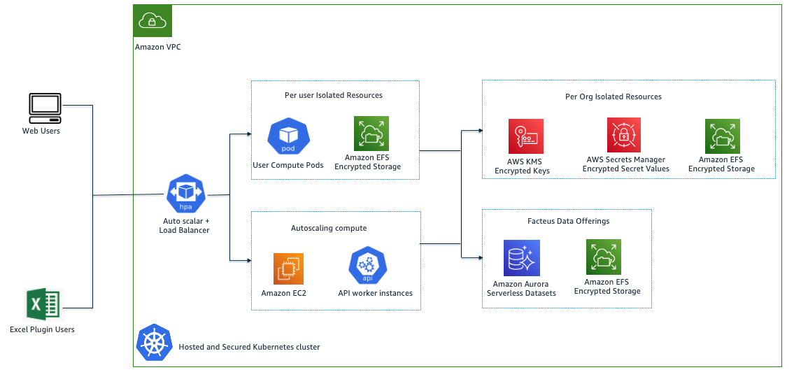
To understand better, let’s consider the use case in Figure 2, where on-premises applications need access to AWS resources.
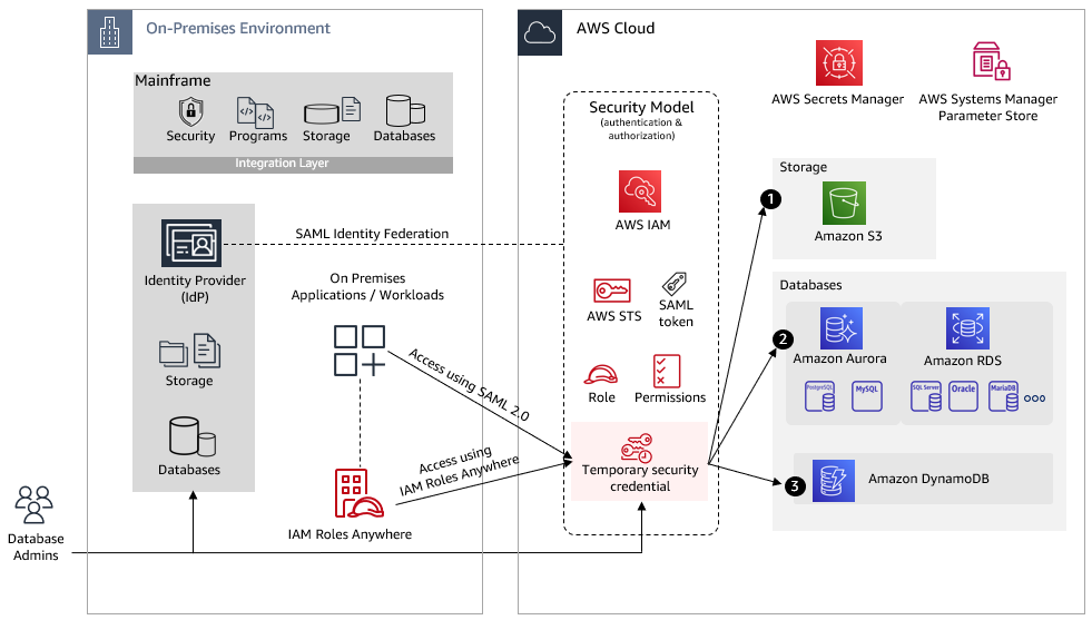
Figure 2. Access to resources that are created or already migrated to AWS from on-premises
Applications can get temporary security credentials through SAML or IAM Roles Anywhere as explained earlier. The next sections explain setting up access to the resources in Figure 2 using temporary credentials.
1. Amazon S3
On-premises applications can access Amazon S3 using the REST API or the AWS SDK to perform certain actions (such as GetObjects or ListObjects):
- Access is provided based on the permissions attached with the assumed role. You can restrict access further by using resource-based policies that include bucket policies, bucket access control lists (ACLs) and object ACLs. Learn more about access policy guidelines in the Amazon S3 User Guide.
- You can also simplify by creating Amazon S3 access points for your application to perform object-level operations in your S3 bucket. Each access point has distinct permissions and network controls that S3 applies for any request made through it.
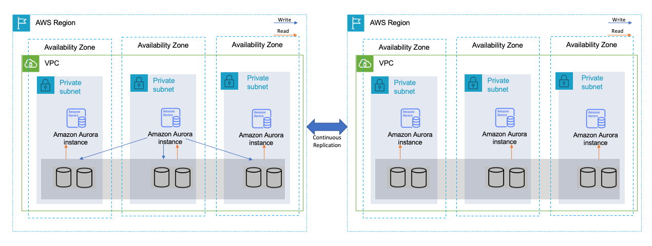
2. Amazon RDS and Amazon Aurora
AWS Secrets Manager helps you store credentials for Amazon RDS and Amazon Aurora. You can also set up automatic rotation of your database secrets to meet your security and compliance needs. Applications can retrieve secrets using AWS SDKs and AWS CLI.
Additional configuration values can be stored in AWS Systems Manager Parameter Store, which provides secure, hierarchical storage for configuration data management such as passwords, database strings and license codes as parameter values rather than hard coding them in the code.
To access Amazon RDS and Amazon Aurora:
-
- You can launch Amazon RDS DB instances into a virtual private cloud (VPC). A client application can access DB instance through the internet or through the private network only using an established connection from on-premises to the AWS environment.
- On-premises applications can connect to a relational database using a database driver such as Java Database Connectivity (JDBC). The application can retrieve database connection details (such as database URL, port, or credentials) from AWS Secrets Manager and AWS Systems Manager Parameter Store through API calls and can use them for the database connection.
- Database admins can access AWS Management Console through an assumed role and can have access to database credentials from AWS Secrets Manager in order to connect directly with the database. For certain administration tasks (such as cluster setup, backup, recovery, maintenance, and management), they will need access to the Amazon RDS management console.
- Amazon RDS also provides IAM database authentication option for MariaDB, MySQL, and PostgreSQL. You can authenticate without a password when you connect to a DB instance. Instead, you use an authentication token. For more information, go to IAM database authentication.
3. Amazon DynamoDB
Applications can use temporary credentials to invoke certain actions using AWS SDKs for DynamoDB. You can create a VPC endpoint for DynamoDB to access DynamoDB with no exposure to the public internet, then restrict access further by using VPC endpoint and IAM policies.
Conclusion
This blog helps you architect an application security model in AWS to provide on-premises access to commonly used resources in AWS.
You can apply security best practices and Zero Trust concepts as you move your legacy applications to the cloud. With AWS, you can build identity and access management with centralized and fine-grained access controls for your workforce and applications.
Start building your security model on AWS:


 Anand Shah is a Big Data Prototyping Solution Architect at AWS. He works with AWS customers and their engineering teams to build prototypes using AWS Analytics services and purpose-built databases. Anand helps customers solve the most challenging problems using art-of-the-possible technology. He enjoys beaches in his leisure time.