Well, it’s been another historic year! We’ve watched in awe as the use of real-world generative AI has changed the tech landscape, and while we at the Architecture Blog happily participated, we also made every effort to stay true to our channel’s original scope, and your readership this last year has proven that decision was the right one.
AI/ML carries itself in the top posts this year, but we’re also happy to see that foundational topics like resiliency and cost optimization are still of great interest to our audience.
(By the way, if you were hoping for more AI/ML content, head on over to our sister channel, the AWS Machine Learning Blog!).
Without further ado, here are our top posts from 2024!
In keeping with Let’s Architect! series, we have our first of three favorites for the year. This set of resources helps you apply Well-Architected standards in practice.
As I said, Let’s Architect! has a winning series, and they’ve got a finger on the pulse of the tech world. This post about machine learning showcases some of the most exciting things happening at AWS.
Figure 3. Let’s Architect
If you’re more interested in generative AI, you can also take a look at another post from 2024: Let’s Architect! GenAI
Preparedness is another common theme in this year’s favorites. Michael, John, and Saurabh are well-versed in multi-Region architecture, and they’re here to share some strategies to contain failure impact.
Figure 4. When the application experiences an impairment using S3 resources in the primary Region, it fails over to use an S3 bucket in the secondary Region.
Let’s talk cost optimization. This post about a three-tier architecture that relies on the AWS Free Tier is a must-read for anyone looking for tips to help them avoid unnecessary costs (and that’s everyone).
Figure 5. Example of a three-tier architecture on AWS
As usual, Haleh & team are pros at making sure the Well-Architected Framework is current and relevant. Take a look at the enhanced and expanded guidance in all six pillars.
One more winning post from Luca, Federica, Vittorio, and Zamira! This collection of developer resources includes new ideas in AWS Lambda, Amazon Q Developer, and Amazon DynamoDB.
Frugality AND Well-Architected? What a winning combo! This post, inspired by the 2023 re:Invent keynote, outlines the seven laws of Frugal Architecture.
And finally, our number one post of the year! Amit and Luiz showcase a customer solution with real-world applications that builds on the guidelines of other posts in this list! Well done!
Figure 10. The Pilot Light scenario for a 3-tier application that has application servers and a database deployed in two Regions
Thank you!
As always, thanks to our contributors for their dedication and desire to share, and to you, our readers! We would be nothing with you. Literally.
For other top post lists, see our Top 10 and Top 5 posts from previous years.
As winter maintains its hold over where I live in the Netherlands, rare moments of sunlight become precious gifts. This weekend offered one such treasure—while cycling along a quiet canal, golden rays broke through the typically gray Dutch sky, creating a perfect moment of serenity. These glimpses of brightness feel particularly special during January, when daylight can be scarce in our corner of Europe. As we move deeper into 2025, the third week of the new year brings both reflection and forward momentum. While global conversations swirl around technological advancements, it’s these small, personal moments that remind us to pause and appreciate the simple pleasures among our rapidly evolving world.
Let’s look at the last week’s new announcements.
Last week’s launches Here are the launches that got my attention.
AWS Mexico (Central) Region – In February 2024, we announced plans to expand infrastructure in Mexico, and we’ve now launched the AWS Mexico (Central) Region with three Availability Zones and API code mx-central-1. This marks the first AWS infrastructure Region in Mexico and adds to our growing presence in Latin America. The new Region provides you with local workload management, data storage capabilities, enhanced performance with lower latency, and robust security standards. It features advanced cloud technologies, including cutting-edge artificial intelligence and machine learning (AI/ML) capabilities with purpose-built processors, comprehensive security capabilities with support for 143 security standards and compliance certifications. With this launch, AWS now spans 114 Availability Zones within 36 geographic Regions.
AWS Management Console now supports simultaneous sign-in for multiple AWS accounts – Using multi-session capability in the AWS Management Console, you can now sign-in to multiple AWS accounts and manage your resources in a single browser. You can sign in to up to 5 sessions and this can be any combination of root, AWS Identity and Access Management (IAM), or federated roles in different accounts or in the same account. You can scale your applications using multiple accounts following AWS best-practice guidelines. You can use accounts for different environments, such as development, testing, and production, and compare resource configurations and status across multiple accounts for troubleshooting application issues and other application related jobs.
Introducing new larger sizes on Amazon EC2 Flex instances – We’re announcing the general availability of two new larger sizes (12xlarge and 16xlarge) on Amazon Elastic Compute Cloud (Amazon EC2) Flex (C7i-flex and M7i-flex) instances. The new sizes expand the EC2 Flex portfolio, providing additional compute options to scale up existing workloads or run larger-sized applications that need additional memory. These instances are powered by custom 4th Gen Intel Xeon Scalable processors, which are available only on AWS, and offer up to 15% better performance over comparable x86-based Intel processors used by other cloud providers. Flex instances are the easiest way to get price performance benefits and lower prices for a majority of compute-intensive and general-purpose workloads. They deliver up to 19% better price performance than comparable previous generation instances and are a great first choice for applications that don’t fully utilize the compute resources. Flex instances are ideal for web and application servers, batch processing, enterprise applications, databases, and more. For compute-intensive and general-purpose workloads that need even larger instance sizes (up to 192 vCPUs and 768 GiB memory) or continuous high CPU usage, you can use Amazon EC2 C7i and M7i instances.
We launched existing services and instance types in additional Regions:
Amazon EC2 M8g instances are now available in AWS Europe (Stockholm) – These instances offer larger instance sizes with up to three times more vCPUs and memory compared to Graviton3 based Amazon M7g instances. AWS Graviton4 processors are up to 40% faster for databases, 30% faster for web applications, and 45% faster for large Java applications than AWS Graviton3 processors.
AWS announces new AWS Direct Connect location and expansion in Querétaro, Mexico – The Direct Connect service helps you establish a private, physical network connection between AWS and your data center, office, or colocation environment. These private connections can provide a more consistent network experience than those made over the public internet.
AWS Backup is now available in Asia Pacific (Thailand) Region – Using AWS Backup, you can centrally create and manage backups of your application data, protect your data from inadvertent or malicious actions with immutable recovery points and vaults, and restore your data in the event of a data loss incident.
Amazon GuardDuty is now available in Asia Pacific (Malaysia) Region – You can now use this additional Region to continually monitor and detect anomalous behavior, security threats, and sophisticated multistage attack sequences targeting your AWS accounts to help protect your AWS accounts, workloads, and data.
Amazon S3 Tables are now available in five additional AWS Regions – Amazon S3 Tables deliver the first cloud object store with built-in Apache Iceberg support and the easiest way to store tabular data at scale. S3 Tables are specifically optimized for analytics workloads, resulting in up to three times faster query performance through continual table optimization compared to unmanaged Iceberg tables, and up to ten times higher transactions per second compared to Iceberg tables stored in general purpose S3 buckets.
Other AWS events Check your calendar and sign up for upcoming AWS events.
AWS Summits are free online and in-person events that bring the cloud computing community together to connect, collaborate, and learn about AWS. Stay updated by visiting the official AWS Summit website and sign up for notifications to learn when registration opens for events in your area.
AWS GenAI Lofts are collaborative spaces and immersive experiences that showcase AWS expertise in cloud computing and AI. They provide startups and developers with hands-on access to AI products and services, exclusive sessions with industry leaders, and valuable networking opportunities with investors and peers. Find a GenAI Loft location near you and don’t forget to register.
Establishing and maintaining an effective security and governance posture has never been more important for enterprises. This post explains how you, as a security administrator, can use Amazon Web Services (AWS) to enforce resource configurations in a manner that is designed to be secure, scalable, and primarily focused on feature gating.
In this context, feature gating means that newly supported AWS features and configurations can’t be used unless you explicitly approve them. With feature gating, you maintain control over your AWS environment when new services and capabilities are introduced.
This blog post demonstrates a unique approach to giving users, such as DevOps teams, controlled flexibility within safe boundaries by allowing resource provisioning that uses only approved configurations. This approach also accommodates configurations that will be supported in future versions of the resource, keeping them restricted until explicitly approved, as shown in Figure 1.
Figure 1: Restrict resource provisioning to approved configurations only
Apply your resource configuration enforcement
As shown in Figure 2, our solution for resource configuration enforcement (RCFGE) uses AWS CloudFormation Hooks. By using Hooks, you can run custom logic during the provisioning of resources. These are proactive controls because you inspect and enforce resource configurations before the resource is created, updated, or deleted.
Your Hook will only be effective if CloudFormation supports the AWS resources that you are using and if you implement a service control policy (SCP) that helps prevent users from provisioning resources outside of CloudFormation.
Figure 2: How CloudFormation Hooks work
The flow shown in Figure 2 consists of the following five steps:
DevSecOps registers and configures a CloudFormation Hook in the account.
DevOps specifies a CloudFormation template that defines the required resources and configurations.
CloudFormation creates a new stack resource, starting the provisioning process based on the template.
The Hook is triggered before provisioning for each resource that’s defined in the template, and runs custom validation logic.
If the validation checks pass, CloudFormation proceeds with provisioning; if not, the process is terminated.
Make your solution scalable
To achieve scalable operations, you should implement a reusable and generic Hook that targets all supported CloudFormation resource types. This Hook enforces resource configuration by loading resource specification files from an external object storage, such as an Amazon Simple Storage Service (Amazon S3) bucket.
These specification files define validation rules in a declarative language. Using this approach, you can add and remove resource configuration validation rules by editing the declarative files. When you externalize custom logic as decoupled validation rules from the Hook, DevSecOps personnel can manage these rules at scale without affecting your infrastructure.
Figure 3: Externalize custom logic as validation rule files in an S3 bucket
Figure 3 shows how the solution has been revised to support this approach. Steps 1–3 are the same as in the flow shown in Figure 2:
DevSecOps registers and configures a CloudFormation Hook in the account.
DevOps specifies a CloudFormation template that defines the required resources and configurations.
CloudFormation creates a new stack resource, starting the provisioning process based on the template.
The Hook is triggered before provisioning for each resource that’s defined in the template.
The Hook loads the relevant resource specification file from the S3 bucket and executes the validation rules against the current resource in the CloudFormation template.
If the validation checks pass, CloudFormation proceeds with provisioning; if not, the process is terminated.
You need to configure the Hook schema and the Hook configuration schema to evaluate the configurations of all supported resources across your AWS accounts before changes are provisioned. This setup should cover create, update, and delete operations so that the Hook can help prevent non-approved configurations across stacks.
By using AWS CloudFormation Guard, you can externalize validation rules from the Hook, as described in Extend your pre-commit hooks with AWS CloudFormation Guard. Guard is an open source, general purpose, policy-as-code (PaC) evaluation tool that validates CloudFormation templates against custom rules to help you stay aligned with your organizational policies. For example, the CT.S3.PR.1 rule specification demonstrates a Guard rule that requires an S3 bucket to have its settings configured to block public access. These validation rules apply to currently supported AWS resource configurations and features, but they don’t restrict potential future properties.
Boost your solution with feature gating
Your risk model might lead you to look for mechanisms that further restrict the AWS resource configurations that you allow in your environments. As you will see, the proposed solution restricts authorized workforce users so that they can use new configurations only if you enable them. The proposed approach uses feature gating because it continues to enforce your configurations even when AWS adds new options for your resources.
Guard aims to validate required constraints; but to meet the feature gating objective, you should implement validation rules that check whether resource configurations fulfill structural constraints described by the restricted version of CloudFormation resource schemas. These schemas help you confine the possible resource configurations that can be provisioned in your environment no matter what new configurations AWS introduces.
Figure 4: Enforce resource configuration with restricted resource schema templates
Figure 4 shows an updated version of the same flow where validation rules are implemented by using restricted resource schema templates, which are stored in an S3 bucket. These templates are based on the original CloudFormation resource schemas, representing a snapshot of these schemas at a specific point in time. Steps 1–4 are the same as in the flow shown in Figure 3:
DevSecOps registers and configures a CloudFormation Hook in the account.
DevOps specifies a CloudFormation template that defines the required resources and configurations.
CloudFormation creates a new stack resource, starting the provisioning process based on the template.
The Hook is triggered before provisioning for each resource that’s defined in the template.
The Hook loads the relevant restricted resource schema template file from the S3 bucket and uses it to execute schema validation against the current resource in the CloudFormation template.
If the validation checks pass, CloudFormation proceeds with provisioning; if not, the process is terminated.
A restricted resource schema template is a subset of its corresponding original CloudFormation resource schema. It includes additional constraints that limit certain properties to specific values and patterns or exclude certain properties entirely. Furthermore, these templates contain placeholders that you fill in with runtime values, such as the account ID, which your Hook provides as part of the Hook context.
As shown in Figure 5, the flow within the RCFGE CloudFormation Hook involves the following steps:
The CloudFormation Hook is invoked with the Hook context and the resource’s configuration JSON object.
The Hook loads the restricted resource schema template from the S3 bucket and substitutes placeholders with the Hook context runtime values, producing a valid JSON schema.
The Hook validates the stack’s resource configuration JSON object against the schema. If it returns OperationStatus.SUCCESS, then CloudFormation proceeds with the provisioning process. If it returns OperationStatus.FAILED, then CloudFormation terminates the provisioning process.
If a restricted resource schema template for a CloudFormation resource type isn’t found in the S3 bucket, the schema validation step fails by default.
Sample excerpt of a restricted schema template for an S3 bucket resource
The following is an excerpt from a restricted schema template for an S3 bucket. At runtime, your Hook processes this template, substituting the placeholders with relevant values from the Hook context. In this example, the Hook replaces the <accountID> placeholder in the topic’s pattern with the actual account ID. The resulting JSON schema disallows additional properties beyond those defined by the schema and restricts the Amazon Simple Notification Service (Amazon SNS) topics that can be used for event notifications.
Note: In the code samples that follow, we’ve omitted some code for brevity—we’ve indicated these omissions with three periods: ...
CloudFormation template for an S3 bucket that adheres to the restricted schema
Let’s assume that your account ID is 111122223333. The account ID is propagated to the Hook through the Hook context.
The following is an excerpt from a CloudFormation template that aligns with the restricted schema for an S3 bucket instantiated from the template shown previously. As a result, your Hook allows the corresponding CloudFormation stack to proceed.
CloudFormation template for an S3 bucket that diverges from the restricted schema (example 1)
The following is an excerpt from a CloudFormation template that doesn’t align with the restricted schema for an S3 bucket instantiated from the template shown previously because it attempts to configure the Amazon SNS topic for the notification configuration, which uses an Amazon Resource Name (ARN) of another account. As a result, your Hook causes the corresponding CloudFormation stack to fail.
CloudFormation template for an S3 bucket that diverges from the restricted schema (example 2)
The following is an excerpt from a CloudFormation template that doesn’t align with the restricted schema for an S3 bucket instantiated from the template shown previously. This time, it violates your feature gating objective by attempting to use a new, imaginary feature of an S3 bucket that isn’t approved for use by your restricted schema for an S3 bucket. As a result, your Hook causes the corresponding CloudFormation stack to fail.
If a security control itself isn’t protected adequately, it becomes a weak link in the security chain. For example, a surveillance camera (a physical security control) that isn’t securely mounted can be removed, rendering it useless. This principle also applies to your RCFGE solution.
Next, we will show you how to isolate management activities to a dedicated account and use SCPs as preventative controls.
Isolate RCFGE management in a dedicated account
Organizing your AWS environment by using multiple accounts is a best practice because it enhances security, simplifies management, and allows for better resource isolation and cost tracking. Isolating the operation and management of your RCFGE solution in its own dedicated account is essential for securing the solution’s resources.
With AWS CloudFormation StackSets, you can deploy and manage RCFGE stacks across multiple accounts and AWS Regions from a single central administrator account. This provides consistent and scalable infrastructure while maintaining centralized governance. With this functionality, you can deploy the RCFGE resources to existing accounts and automatically include new accounts as you add them to your organization, simplifying RCFGE management and providing uniformity across your environments. For more information, see Deploy CloudFormation Hooks to an Organization with service-managed StackSets.
Figure 6 shows how to extend that idea so that you can operate the RCFGE solution at scale while maintaining isolation and the separation of duties. The solution operates across three key account types:
Management account –use this account to create your organization and designate the CloudFormation StackSets delegated administrator account.
Delegated administrator account – this account serves as the centralized management point for the RCFGE solution. It contains a continuous integration and continuous delivery (CI/CD) pipeline that provisions RCFGE resources across the organization by using CloudFormation StackSets with service managed permissions. The account hosts a centralized S3 bucket that stores the RCFGE restricted resource schema templates. The security engineering team uses this account to submit Hook code and restricted resource schema template changes, which trigger the CI/CD pipeline.
Member accounts – each member account contains an RCFGE StackSet instance and an AWS Identity and Access Management (IAM) role for provisioning RCFGE resources. It also includes a CloudFormation Hook and an IAM role that allows the Hook to access the centralized S3 bucket with RCFGE restricted resource schema templates.
Figure 6: Securely operate the RCFGE solution
Let’s explore how the RCFGE solution architecture enforces resource configuration step by step, as shown in Figure 7.
Figure 7: CloudFormation stack deployment flow with RCFGE validation and enforcement
DevOps initiates the deployment by specifying a CloudFormation template that defines the resources and configurations needed.
CloudFormation creates a new stack resource, initiating the resource provisioning process based on the provided template.
The RCFGE CloudFormation Hook is triggered for each resource defined in the CloudFormation template.
The Hook loads the corresponding restricted resource schema template from the S3 bucket.
The Hook validates a resource configuration:
The Hook processes the restricted resource schema template to create a JSON schema.
It uses this JSON schema to validate the current resource in the CloudFormation template.
If the resource is invalid according to the schema, the provisioning process is terminated.
If the current resource passes validation, CloudFormation proceeds with the resource provisioning process by creating and configuring the resources as specified in the template.
Use SCPs as preventive controls for your organization to help protect RCFGE
The following SCP excerpt accomplishes three objectives:
Implements a statement (see AllowedListActions) to explicitly specify the access that is allowed while other access is implicitly blocked.
Implements control objectives to help prevent changes to resources set up by the RCFGE solution (see ProtectRCFGEResources and ProtectStackSetExecutionRole).
Makes sure that AWS resource provisioning does not occur outside of CloudFormation (see ProvisionResourcesViaCloudFormationOnly).
In this SCP excerpt, the ProvisionResourcesViaCloudFormationOnly statement restricts CloudFormation stacks to being managed only through forward access sessions (FAS) in AWS IAM.
The ProvisionResourcesViaCloudFormationOnly statement explicitly prohibits direct create, update, and delete actions for all supported resources used in your environment. If needed, split this statement into multiple parts so you don’t exceed SCP size limits, while providing comprehensive coverage of your resources to make sure that they are provisioned and managed only through CloudFormation.
The ProtectStackSetExecutionRole statement in this example assumes that CloudFormation trusted access is activated with AWS Organizations, which is required by StackSets to deploy across accounts and Regions by using service managed permissions.
To allow the Hook to retrieve the necessary restricted resource schema templates, member accounts must be able to access the S3 bucket that contains the RCFGE templates. The following code sample shows the bucket policy for the S3 bucket that contains the RCFGE templates.
As shown in the following code sample, the RCFGEHookExecutionRole IAM role in member accounts has a policy that grants read-only access to the RCFGE templates that are stored in an S3 bucket in the RCFGE delegated administrator account, where 555555555555 represents the account ID.
In the following code sample, the RCFGEHookExecutionRole IAM role in member accounts has a trust policy that allows it to be assumed only by the relevant CloudFormation service principals, where 444455556666 represents the account ID of the member account.
Define baseline configuration for RCFGE and continuous monitoring with AWS Config
Defense in depth is an effective strategy because if one line of defense fails, additional layers are in place to help stop threats at subsequent points. With AWS Config, you can capture the configuration of RCFGE resources over time. You can set up AWS Config custom rules to automatically assess the compliance of your RCFGE resources against predefined policies. For example, you can use an AWS Config custom rule to make sure that the RCFGE Hook hasn’t been altered or removed.
Conclusion
In this post, you learned how to use CloudFormation Hooks to create a resource configuration enforcement (RCFGE) solution on AWS that is designed to be secure and scalable and that supports feature gating. Using this approach, you, as a security administrator, can maintain strict control over resource configurations and feature adoption across your AWS environments. The solution provides a balanced approach to governance, so that DevOps teams have the flexibility to work within approved boundaries while making sure that new AWS features are only accessible after explicit approval.
If you have feedback about this post, submit comments in the Comments section. For questions, start a new thread on the CloudFormation re:Post or contact AWS Support.
We’re pleased to announce an enhanced version of the AWS Secrets Manager transform: AWS::SecretsManager-2024-09-16. This update is designed to simplify infrastructure management by reducing the need for manual security updates, bug fixes, and runtime upgrades.
AWS Secrets Manager helps you manage, retrieve, and rotate database credentials, API keys, and other secrets throughout their lifecycles. Some AWS services offer managed rotation of secrets, but for other secrets, you perform rotation by using an AWS Lambda function that updates your secret and the database or service.
The AWS::SecretsManager transforms are used in conjunction with the AWS::SecretsManager::RotationScheduleresource type and HostedRotationLambdaproperty to automatically extend your CloudFormation template to include a nested stack that creates the appropriate rotation Lambda function for your database or service. The transforms provide a convenient way to deploy an AWS vended rotation Lambda function into your own account as part of your CloudFormation templates, without having to rely on creating rotation Lambda functions through the AWS Serverless Application Repository or the AWS Management Console.
In this post, we’ll explore the new features of the transform, compare them to the previous version, and guide you through updating an existing Lambda function that was created using the old transform version to use the new transform version.
New features in AWS::SecretsManager-2024-09-16
The new transform version introduces several enhancements over the previous version (AWS::SecretsManager-2020-07-23):
Automatic Lambda upgrades: Your rotation Lambda functions’ runtime configuration and internal dependencies now update automatically when you update your CloudFormation stacks. This helps you verify that you’re using the most secure and stable versions of Secrets Manager vended rotation Lambda function code and runtimes. Currently, AWS Lambda supports Python runtimes 3.9 and above. With Python 3.8 being deprecated, this feature allows for a seamless transition to newer supported runtimes. For more information on runtime deprecations, see the AWS Lambda runtimes documentation and the Python version guide.
Additional resource attributes: The new transform now supports additional resource attributes for the AWS::SecretsManager::RotationSchedule resource type when used with the HostedRotationLambda property. The following attributes are applied to the nested stack (of type AWS::CloudFormation::Stack) that creates the rotation Lambda function:
The following table shows which resource attributes are supported by the two versions of the Secrets Manager transform.
Attribute
AWS::SecretsManager-2020-07-23
AWS::SecretsManager-2024-09-16
DeletionPolicy
Supported
Supported
UpdateReplacePolicy
Supported
Supported
CreationPolicy
Not Supported
Supported
DependsOn
Not Supported
Supported
Metadata
Not Supported
Supported
UpdatePolicy
Not Supported
Supported
Condition
Not Supported
Supported
Important considerations
Before you use the AWS::SecretsManager-2024-09-16 transform, it’s essential to be aware of the following considerations so that you can make sure your CloudFormation stacks are properly created or updated:
Non-backward compatibility: The new transform version isn’t backward compatible with the previous version. If you downgrade from AWS::SecretsManager-2024-09-16 to AWS::SecretsManager-2020-07-23, the additional resource attributes won’t be supported, which might change the behavior of existing stacks.
Rollback behavior during upgrade: When you upgrade to the AWS::SecretsManager-2024-09-16 transform from the previous version and a stack rollback occurs for any reason, the rotation Lambda function might not revert to its previous state. This is because the older transform’s nested stack might not use the same Lambda deployment package that was used before the upgrade.
Direct Lambda changes: If you make direct changes to the Lambda function created by the new transform outside of a CloudFormation stack update, those modifications might be overwritten during subsequent CloudFormation stack updates or rollbacks.
Lambda runtime management: When you use the new transform version, the rotation Lambda function’s runtime aligns with the compiled binaries that are vended in Secrets Manager rotation Lambda templates, without you needing to specify a Runtime value in the HostedRotationLambda property. If you specify a Runtime value, make sure it’s the same version that is supported by Secrets Manager vended rotation Lambda templates. Otherwise, the Lambda runtime will be incompatible with the binaries that are published in the rotation Lambda function. For more information on the supported runtime, see the rotation function templates documentation.
End of support plans: AWS Secrets Manager will end support for the previous transform version (AWS::SecretsManager-2020-07-23) in the future. We recommend that you migrate your stacks to the new transform to benefit from improvements and security enhancements going forward.
How to upgrade
To upgrade to the new transform version, follow these steps:
Review your existing CloudFormation stacks that use the AWS::SecretsManager-2020-07-23 transform.
Update your CloudFormation stack templates to use AWS::SecretsManager-2024-09-16 in the Transform key at the top of your template: Transform: AWS::SecretsManager-2024-09-16
If you have previously defined a Runtime value in the HostedRotationLambda property, remove it from your template so that your rotation Lambda function’s runtime is updated properly in future stack updates.
Incorporate the new resource attributes as needed. We recommend that you minimize all other template changes while upgrading to reduce the likelihood of rollbacks.
Deploy the changes by updating your CloudFormation stack with the revised template.
By following these steps, your Secrets Manager vended rotation Lambda functions will benefit from the latest improvements and security enhancements. Remember to test the changes in a non-production environment before you apply them to your production stacks. If you encounter any issues during the upgrade process, refer to our documentation or contact AWS Support for assistance.
If you have feedback about this post, submit comments in the Comments section below. If you have questions about this post, contact AWS Support.
Today we are announcing the integration of AWS CloudFormation Hooks with AWS Cloud Control API (CCAPI). This integration enables the use of hooks to validate the configuration of resources being provisioned through CCAPI. In this blog post, we will explore the integration between CloudFormation Hooks and CCAPI by configuring an existing hook to work with CCAPI and then test that hook using the AWS CLI and Terraform.
Understanding CloudFormation Hooks
CloudFormation Hooks integrate seamlessly with your CloudFormation and CCAPI requests to perform validation of your resource configuration during resource create and update operations. You can create hooks using AWS Lambda, AWS CloudFormation Guard rules, or using code and the CloudFormation Command Line Interface (CFN-CLI). A hook can be triggered on change sets, entire stack templates, or by each resource and it will return back any discovered misconfiguration information. Hooks can be configured to warn or fail on the operation allowing you to prevent any misconfigured resources from being deployed in your account. Some key benefits of using CloudFormation Hooks with CCAPI include:
Enforcing security best practices
Applying organizational policies to resource deployments
Optimizing resource configurations for cost and performance
For this post we are going to use the new AWS CloudFormation Guard (Guard) hook AWS::Hooks::GuardHook. Guard is an open-source policy-as-code tool that allows you to validate your infrastructure configurations against company policy guidelines. It provides a domain-specific language (DSL) for writing rules to check both required and prohibited resource configurations. The new AWS::Hooks::GuardHook allows you to use the Guard DSL inside of a hook so you can easily implement your organizations guidelines. The result is you can use the same Guard rules in our local development environment, continuous integration and continuous deployment pipelines, and at deployment time (using hooks). To learn more about AWS::Hooks::GuardHook you can look at the blog.
This is what the configuration of the current Guard hook looks like.
This hook has been configured to log the Guard validation report to an Amazon Simple Storage Service (S3) bucket. Additionally, this hook is configured to use a rule from the AWS CloudFormation Guard registry. This rule will validate that an S3 bucket is using versioning. This hook is configured with an alias named My::Hooks::Guard.
Here is the rule for reference. This rule will validate that the property VersioningConfiguration is provided and that its value is Enabled.
let s3_buckets_versioning_enabled = Resources.*[ Type == 'AWS::S3::Bucket' ]
rule S3_BUCKET_VERSIONING_ENABLED when %s3_buckets_versioning_enabled !empty {
  %s3_buckets_versioning_enabled.Properties.VersioningConfiguration exists
  %s3_buckets_versioning_enabled.Properties.VersioningConfiguration.Status == 'Enabled'
  <<
    Guard Rule Set: ABS-CCIGv2-Standard
    Controls: section4b-design-and-secure-the-cloud-14-standard-workloads,section4b-design-and-secure-the-cloud-15-standard-workloads
    Violation: S3 Bucket Versioning must be enabled.
    Fix: Set the S3 Bucket property VersioningConfiguration.Status to 'Enabled' .
  >>
}
Configuring the hook to work with CCAPI
This announcement adds a new hook target that can easily be configured on your existing or new hooks. To configure the hook to work with CCAPI you will edit the configuration to include a new TargetOperations value of CLOUD_CONTROL. This hook is only enabled to execute on CREATE and UPDATE operations. Additionally HookInvocationStatus is ENABLED which will execute the hook and FailureMode will tell the hook to FAIL the operation if the resource is not compliant.
By using TargetOperations of ["RESOURCE", "CLOUD_CONTROL"] the Guard rules will work the same across CloudFormation resource operations and CCAPI operations.
Testing the hook using AWS CLI
Test your hook using the AWS CLI which allows us to create, update, delete, and list resources.
Start by creating a S3 bucket using CCAPI. In this example you are providing no properties for creating the S3 bucket. Run the command aws cloudcontrol create-resource --type-name AWS::S3::Bucket --desired-state {} Response:
Get the request status by using the RequestToken from the response above. Run the command aws cloudcontrol get-resource-request-status --request-token 2c7b6f5e-4083-4ef8-9a23-5c81472540b1
Response:
{
    "ProgressEvent": {
        "TypeName": "AWS::S3::Bucket",
        "RequestToken": "2c7b6f5e-4083-4ef8-9a23-5c81472540b1",
        "HooksRequestToken": "4a193a00-4c76-41fe-87b8-75b838f00bbe",
        "Operation": "CREATE",
        "OperationStatus": "FAILED",
        "EventTime": "2024-11-05T09:41:40.785000-08:00",
        "StatusMessage": "Request [4a193a00-4c76-41fe-87b8-75b838f00bbe] failed \ndue to the following failed invocations: [My::Hooks::Guard]"
    },
    "HooksProgressEvent": [
        {
            "HookTypeName": "My::Hooks::Guard",
            "HookTypeVersionId": "00000006",
            "HookTypeArn": "arn:aws:cloudformation:eu-central-1:123456789012:type/hook/My-Hooks-Guard/00000001/aws-hooks/AWS-Hooks-GuardHook/00000001.00000005",
            "InvocationPoint": "PRE_PROVISION",
            "HookStatus": "HOOK_COMPLETE_FAILED",
            "HookEventTime": "2024-11-05T09:41:38.978000-08:00",
            "HookStatusMessage": "Template failed validation, the following rule(s) failed: S3_BUCKET_VERSIONING_ENABLED. Full output was written to s3://<my-guard-hook-logging-bocket>/cfn-guard-validate-report/AWS--S3--Bucket-4a193a00-4c76-41fe-87b8-75b838f00bbe-RESOURCE-AWS--S3--Bucket-CREATE-PRE_PROVISION/1730828427591.json",
            "FailureMode": "FAIL"
        }
    ]
}
In the response you will see all hooks that were executed and their response in relation to the request. This response shows that the hook My::Hooks::Guard failed because of the rule S3_BUCKET_VERSIONING_ENABLED . You are also provided a s3 location for where the full Guard output is stored.
You can get the Guard results file by using the following command. Replace <path-from-previous-output> with the path provided in the previous output. Run the command aws s3 cp s3://<path-from-previous-output> -
We truncated the output as it can be very verbose.
Testing the hook using Terraform
The Terraform AWS Cloud Control Provider allows you to manage AWS resources using CCAPI and Terraform. By leveraging this provider you get the benefit of using hooks to validate the configuration of Terraform provisioned resources.
Create a new Terraform configuration file named main.tf with the following content:
Run the following commands to initialize Terraform and create an execution plan. Run the command terraform init followed by terraform plan.
Apply the configuration by running. Run the command terraform apply
Response:
...
awscc_s3_bucket.example: Creating...
╷
│ Error: AWS SDK Go Service Operation Incomplete
│
│   with awscc_s3_bucket.example,
│   on main.tf line 14, in resource "awscc_s3_bucket" "example":
│   14: resource "awscc_s3_bucket" "example" {
│
│ Waiting for Cloud Control API service CreateResource operation completion returned: waiter state transitioned to FAILED. StatusMessage: Request [d417b05b-9eff-46ef-b164-08c76aec1801] failed
│ due to the following failed invocations: [My::Hooks::Guard]. ErrorCode:
╵
In this response you can see that the hook My::Hooks::Guard failed and the request token is d417b05b-9eff-46ef-b164-08c76aec1801
You can get details on the hook invocation by running the command aws cloudformation list-hook-results --hook-target TargetType=CLOUD_CONTROL,TargetId=d417b05b-9eff-46ef-b164-08c76aec1801Response:
{
    "TargetType": "CLOUD_CONTROL",
    "TargetId": "d417b05b-9eff-46ef-b164-08c76aec1801",
    "HookResults": [
        {
            "InvocationPoint": "PRE_PROVISION",
            "FailureMode": "FAIL",
            "TypeName": "My::Hooks::Guard",
            "TypeVersionId": "00000006",
            "Status": "HOOK_COMPLETE_FAILED",
            "HookStatusReason": "Template failed validation, the following rule(s) failed: S3_BUCKET_VERSIONING_ENABLED. Full output was written to s3://my-company-guard-hooks-eu-central-1/cfn-guard-validate-report/AWS--S3--Bucket-d417b05b-9eff-46ef-b164-08c76aec1801-RESOURCE-AWS--S3--Bucket-CREATE-PRE_PROVISION/1730829108790.json"
        }
    ]
}
As with the AWS CLI you now know what rule failed and additional you have the S3 bucket location for the Guard log file.
You can get the Guard results file by running the command aws s3 cp s3://<path-from-previous-output> -. Replace <path-from-previous-output> with the path provided in the previous output.Response:
CloudFormation Hooks provide a powerful way to enforce best practices and compliance for your AWS resources. By leveraging CloudFormation Hooks and the Cloud Control API you can create consistent validation of your resources before deployment across many of your infrastructure as code solutions.
AWS CloudFormation is a service that allows you to define, manage, and provision your AWS cloud infrastructure using code. To enhance this process and ensure your infrastructure meets your organization’s standards, AWS offers CloudFormation Hooks. These Hooks are extension points that allow you to invoke custom logic at specific points during CloudFormation stack operations, enabling you to perform validations, make modifications, or trigger additional processes. Among these, the Lambda hook is a powerful option provided by AWS. This managed hook allows you to use Lambda functions to validate your CloudFormation templates before deployment. By using a Lambda hook, you can invoke custom logic to check infrastructure configurations on create or update or delete CloudFormation resources or stacks or change sets, as well as create or update operations for AWS Cloud Control API (CCAPI) resources. This enables you to enforce defined policies for your infrastructure-as-code (IaC), preventing the deployment of non-compliant resources or emitting warnings for potential issues. In this blog post, you will explore how to use a Lambda hook to validate your CloudFormation templates before deployment, ensuring your infrastructure is compliant and secure from the start.
Introducing Lambda Hook
The Lambda hook is an AWS-provided managed hook with the type AWS::Hooks::LambdaHook. It simplifies the integration of custom logic into CloudFormation stacks. This powerful feature allows you to focus on building and testing your custom logic as a Lambda function, without the complexity of creating a hook from scratch.
By using the Lambda hook, you can activate a pre-built hook and deploy your custom logic into a Lambda function using familiar tools like AWS CLI or AWS Serverless Application Model (SAM) or AWS Cloud Development Kit (CDK). This approach reduces the number of components you need to manage in your workflow, allowing for more streamlined operations. The Lambda hook also offers flexible evaluation capabilities, enabling you to respond to specific template properties or configurations as needed.
One of the key advantages of the Lambda hook is the enhanced control it provides. You can benefit from features such as VPC integration, local logging, and granular resource management, all while leveraging the power of AWS Lambda functions. To get started with the Lambda hook, you’ll need to activate it in your AWS account. This activation process eliminates the need for authoring, testing, packaging, and deploying a custom hook using the AWS CloudFormation Command Line Interface (CFN-CLI), significantly simplifying your workflow.
Example Use Case: S3 Bucket Versioning Validation
This blog post demonstrates using the Lambda hook to validate S3 Bucket versioning before deployment. While focused on S3 buckets, this approach can be applied to other resource types, properties, stack, and change set operations.
By leveraging the Lambda hook, you’ll streamline custom logic integration into your CloudFormation stacks. The process involves:
This example showcases how to enhance your infrastructure-as-code practices, ensuring compliant and secure deployments from the start.
Architecture
This section shows you how the Lambda hook and Lambda function work together to enhance your CloudFormation deployments.
Lambda hook and Lambda function
First, you need to create a Lambda function with the business logic to respond to the hook. Then, you need to create an IAM execution role with the necessary permissions to invoke the Lambda Function. Once you have the Lambda function and the IAM execution role, you can activate the AWS provided Lambda hook. Follow the steps in the documentation to activate a Lambda hook from the AWS console. Alternatively, you can activate it using the AWS Command Line Interface (AWS CLI) by using the activate-type and set-type-configuration commands. Lastly, you can also use AWS::CloudFormation::LambdaHook as a CloudFormation resource to activate and configure Lambda hook from a CloudFormation template. You can share this resource across your other accounts and regions using AWS CloudFormation StackSets by following this blog.
Lambda hook in action
The following diagram and explanation illustrate the step-by-step workflow of how Lambda hook integrates with your CloudFormation operations, providing a visual representation of the process from template creation to resource deployment or modification.
Diagram 1: Lambda hooks in action
The architecture diagram illustrates the step-by-step flow of how the Lambda hook is used during a CloudFormation stack operation.
Author a template: Author a CloudFormation template, including the necessary resources to configure.
Create the stack: The CloudFormation stack creation process has started, but the process of creating the defined resources in the template has not yet begun.
Request is received by CloudFormation service: When a resource creation, update, or deletion is requested, the CloudFormation service receives the request.
Invoke the Hook: The CloudFormation service then invokes the Lambda hook.
The hook invokes your the Lambda Function: The Lambda hook, in turn, triggers the execution of the Lambda function that was defined in the hook activation.
The Lambda function processes the request and responds back to the Hook: The Lambda function processes the request, performing validation, or additional tasks as required. The Lambda function then responds back to the Lambda hook.
The stack workflow progresses further in either continuing the resource creation/update/deletion with/without a warning or fails: Based on the Lambda function’s output, the Lambda hook either allows the stack operation to proceed with the resource operation (for example, creation of the resource), or deny the resource operation causing a rollback of the stack.
This workflow demonstrates how Lambda hook seamlessly integrates into the CloudFormation stack deployment process, allowing you to implement custom validations, enforce policies, and extend the capabilities of your infrastructure-as-code deployments through the power of Lambda functions. By leveraging the Lambda hook and the custom Lambda function, customers can extend the capabilities of their CloudFormation deployments, enabling advanced use cases such as resource validation, or additional task execution.
Sample Deployment
This section shows you how to enable the Lambda hook, which is of type AWS::Hooks::LambdaHook, and add the business logic in the Lambda function to validate the versioning configuration of an S3 bucket. The sample solution shown in this blog post demonstrates the hook triggering for the resource type AWS::S3::Bucket, and if you want to trigger this for every resource type, then you can use the Resource filter within Hook filters configuration that can take wildcard"AWS::*::*" as a value or multiple targets of resource types for example "AWS::S3::Bucket", "AWS::DynamoDB::Table", and you’ll also want to make sure that the Lambda Function has the logic to handle the additional resource type. You can also add additional Hook targets , for example to validate your STACK or CHANGE_SET.
In the example used in this blog post, you will configure the hook and activate on create and update operations operations. For more information about TargetFilters, see Hook configuration schema and for more information about Lambda hook see here. With these modifications, you need to consider two important points: First, you will need to handle the business logic to deal with different resource types in your Lambda function code. Second, additional pricing may apply based on your resource usage, for more details see the Lambda pricing page.
Creating the Lambda Function
You can create a Lambda function in several ways – on the AWS Console, using CloudFormation, using AWS CLI, or by directly invoking the API via SDK. In this section, we will cover creating a Lambda function with a few clicks on the AWS console. See Using Lambda with infrastructure as code (IaC) for deploying Lambda Function using SAM CLI, CDK or CloudFormation.
The Lambda Function code is designed to process the event received from the Lambda hook and validate the versioning configuration of the target S3 bucket resource. Here’s a detailed explanation of the code:
The function first extracts the relevant information from the event, including the invocation point and the target resource type.
It then checks if the current invocation point is in the configured HOOK_INVOCATION_POINTS list and if the target resource type is AWS::S3::Bucket. If not, the function returns a success response, skipping the validation for this particular invocation.
Note: this code that skips the validation is put here as a fallback logic in the event the user has not chosen to use TargetFilters. As this is a wildcard hook, without TargetFilters the hook will always be invoked for any AWS resource type described in the template, and since the hook targets preCreate, preUpdate, and preDelete by default, the hook will be invoked for these invocation points by default. To narrow the scope and reduce costs by avoiding to invoke the hook for all AWS resource type targets and invocation points, use TargetFilters.
Next, the function retrieves the resource properties from the event, specifically looking for the VersioningConfiguration property and its Status.
If the VersioningConfiguration property is not present or its Status is not set to Enabled, the function returns a failure response, indicating that the versioning is not enabled for the S3 bucket.
If the versioning is enabled, the function returns a success response.
The function also includes a fallback mechanism to return a failure response in case of any other exceptions. By evaluating this sample code, you can validate the versioning configuration of the S3 bucket during the CloudFormation stack creation and update processes, with your infrastructure-as-code policies.
Enabling Lambda Hook in your AWS Account/Region
Navigate to the AWS CloudFormation service on the AWS Console, then choose “Create Hook” → “with Lambda” from the main Hooks page:
Diagram 2: Create a Hook with Lambda console page
You will see the page explaining how the Lambda function work as a hook.
Diagram 3: Provide a Lambda function to Hook Console page
Provide the Hooks details: the name, the Lambda function it should take, the type, and the mode. You can also create your execution role directly from the console by choosing “New execution role”.
Diagram 3: Provide a Lambda function to Hook Console page
You can review the Lambda hook and activate it from the next page.
Diagram 4: Review Lambda hook Console page
Test a sample
In this section, you will test the hook and the Lambda Function that you activated for a S3 bucket resource.
Create an S3 Bucket without versioning
AWSTemplateFormatVersion: "2010-09-09"

Description: This CloudFormation template provisions an S3 Bucket without versioning enabled

Resources:
  S3Bucket:
    DeletionPolicy: Delete
    Type: AWS::S3::Bucket
    Properties:
      BucketName: !Sub test-bucket-versioning-1-${AWS::Region}-${AWS::AccountId}
You will see the hook invoking Lambda function and the Lambda Function responding back with a failure message since the Versioning is not enabled.
When you create or update a stack with the template above, the Lambda hook will be invoked, and the Lambda Function will respond with a failure message since bucket versioning is not enabled. The Lambda Function code will extract the resourceProperties from the event, check the VersioningConfiguration property, and find that the Status is not set to Enabled. As a result, if you use the example template above where you describe the S3 bucket without versioning enabled, the Lambda Function will send a failure response back to the hook, causing the CloudFormation stack operation to fail as shown in the following screenshot.
Diagram 5: Lambda Hook failure Stack
Create an S3 Bucket with versioning enabled You can try creating an S3 Bucket with versioning enabled to see how Hooks assessment succeeded.
AWSTemplateFormatVersion: "2010-09-09"

Description: This CloudFormation template provisions an S3 Bucket with Versioning enabled

Resources:
  S3Bucket:
    DeletionPolicy: Delete
    Type: AWS::S3::Bucket
    Properties:
      BucketName: !Sub test-bucket-versioning-2-${AWS::Region}-${AWS::AccountId}
      VersioningConfiguration:
        Status: Enabled
In this case, you will see the hook invoking the Lambda function and getting a success message since the Versioning is enabled
When you create a stack with this CloudFormation template, the Lambda hook will be invoked, and the Lambda Function will respond with a success message since the versioning is enabled. The Lambda Function code will extract the resourceProperties from the event, check the VersioningConfiguration property, and find that the Status is set to Enabled. As a result, the Lambda Function will send a success response back to the hook, allowing the CloudFormation stack operation to proceed as shown in the following screenshot.
Diagram 6: Lambda Hook success Stack
By testing these two scenarios, you can verify that the Lambda hook and the associated Lambda Function are working as expected, enforcing the S3 bucket versioning policy during CloudFormation stack operations.
In this blog post, you explored the capabilities of CloudFormation Hooks and how they can be leveraged to extend the functionality of your infrastructure-as-code deployments. Specifically, you learned about the Lambda hook, a pre-built hook that simplifies the process of integrating custom logic into your CloudFormation stacks.
By activating the Lambda hook, and deploying a custom Lambda Function, you were able to validate the versioning configuration of an S3 bucket during the CloudFormation stack creation and update processes. This approach allows you to enforce infrastructure-as-code policies and ensure compliance at the point of deployment, rather than relying on post-deployment checks or indirect governance mechanisms. The ability to leverage familiar tools and workflows, such as the AWS CLI, AWS SAM, CI/CD pipelines, or the AWS CDK, makes it easier to incorporate custom logic into your CloudFormation deployments. This reduces the overhead and complexity associated with traditional hook orchestration and packaging, empowering you to streamline your infrastructure-as-code practices.
As you continue to build and deploy your cloud infrastructure, consider exploring the various CloudFormation Hooks available, for example, see aws-cloudformation/aws-cloudformation-samples and aws-cloudformation/community-registry-extensions GitHub repositories. The approach demonstrated in this blog post can be applied to other resource types supported by CloudFormation, allowing you to validate and enforce policies for a wide range of infrastructure components, from EC2 instances and VPCs to databases and application services.
About the Author
Kirankumar Chandrashekar is a Sr. Solutions Architect for Strategic Accounts at AWS. He focuses on leading customers in architecting DevOps, modernization using serverless, containers and container orchestration technologies like Docker, ECS, EKS to name a few. Kirankumar is passionate about DevOps, Infrastructure as Code, modernization and solving complex customer issues. He enjoys music, as well as cooking and traveling.
Stella Hie is a Sr. Product Manager Technical for AWS Infrastructure as Code. She focuses on proactive control and governance space, working on delivering the best experience for customers to use AWS solutions safely. Outside of work, she enjoys hiking, playing piano, and watching live shows.
In today’s cloud-driven world, maintaining compliance and enforcing organizational policies across your infrastructure is more critical than ever. AWS CloudFormation, a service that enables you to model, provision, and manage AWS and third-party resources through Infrastructure as Code (IaC), has been a cornerstone for automating cloud deployments. While CloudFormation simplifies resource management, ensuring compliance with internal and external standards requires robust tools and strategies to align with organizational and regulatory requirements.
Enter the new managed hook for Guard, a new hook designed to seamlessly integrate compliance into your AWS CloudFormation workflows. AWS CloudFormation Hooks are a powerful tool that allow you to validate and enforce policies during the provisioning and management of resources in your CloudFormation stacks. With a Guard hook, you can now bring your AWS CloudFormation Guard rules directly into your CloudFormation stacks, change sets, and individual resources. This feature eliminates the need to incorporate the Guard runtime into custom hooks, simplifying compliance enforcement and enhancing your security posture.
What is a Guard hook?
A Guard hook is a service-managed CloudFormation Hook that integrates AWS CloudFormation Guard—a policy-as-code tool—directly into your CloudFormation deployment process. AWS CloudFormation Guard uses a domain-specific language (DSL) to define compliance rules in an easily readable and reusable format, enabling you to codify and enforce organizational policies. This hook allows you to automatically validate your CloudFormation templates against these established compliance rules, enforcing policies seamlessly without the need to manage custom Lambda functions or Guard runtimes. By identifying non-compliant resources early, it helps streamline deployments and ensures that your infrastructure aligns with organizational standards right from the start.
Benefits of Using a Guard hook
Guard hooks provide unique advantages by combining the flexibility of CloudFormation Hooks with the expressiveness of the Guard Domain Specific Language (DSL), giving you a powerful tool for infrastructure compliance and security. As a fully managed CloudFormation hook, Guard hooks eliminate the need for a custom hook implementation and management, allowing you to leverage AWS’s service-driven infrastructure to streamline policy enforcement.With a Guard hook, you can express compliance rules and configurations directly in the Guard DSL.
Guard hooks specifically add value by enabling these Guard-based compliance policies to be applied automatically during stack operations. This helps validate that your infrastructure consistently aligns with security and compliance standards, reducing the risks of misconfiguration and non-compliance. Additionally, Guard hooks allow you to take advantage of CloudFormation’s native stack-level and resource-level hooks, adding depth to your compliance by enforcing policies across entire stacks and individual resources alike.
Use Cases
Guard hooks can be applied in various scenarios to enhance compliance and security. In security compliance, for instance, it can ensure that all databases and storage services have encryption enabled or prevent security groups from allowing unrestricted inbound traffic. Regarding resource configuration, it can enforce the use of approved EC2 instance types or require specific tags on all resources for cost tracking and management.
For operational governance, Guard hooks can validate that resources do not exceed predefined thresholds, such as storage size, ensuring that resources are provisioned within acceptable limits. It can also enforce network policies by ensuring the use of approved VPCs and subnets, maintaining network security and compliance with organizational standards.
A resource hook in CloudFormation targets individual resources within a template, such as EC2 instances, S3 buckets, or IAM roles. It is particularly useful for enforcing specific standards or compliance requirements on individual resources, thereby helping customers ensure each one meets defined criteria. For instance, you could use a resource-level hook to enforce that every S3 bucket created through CloudFormation has server-side encryption enabled. In contrast, a stack or change set hook targets the entire CloudFormation stack as a single entity, allowing for the application of guardrails or validation requirements across all resources within the stack collectively. This helps to ensure that the entire stack, not just individual resources, aligns with set policies before the stack is created or updated. For example, a stack-level hook could be used to prevent a stack from containing certain types of resources or to ensure that a specific number of resources are created in each stack. Together, these hooks provide different layers of validation to enforce compliance and configuration standards at both the resource and stack levels.
Getting Started
Getting started with a Guard hook involves configuring the hook, uploading your Guard rules to Amazon S3, activating the hook, and enabling it to run against your CloudFormation stacks. Below are the detailed steps to help you set up and start using Guard Hook effectively.
Pre-requisites Create an Amazon S3 Bucket
If you do not have one already, you will need to create an S3 bucket in your region. This bucket will hold your Guard policy files and optionally the full Guard evaluation output if so desired.
Configuring a Guard hook Create your rule
In this section, you will provide an example of AWS CloudFormation Guard rules that help enforce best practices for Amazon S3 buckets. Please create a file called safebucket.guard and include the following rules:
# Rule Identifier:
#    S3_BUCKET_PUBLIC_WRITE_PROHIBITED
#
# Select all S3 resources from the incoming template (payload)
#
let s3_buckets_public_write_prohibited = Resources.*[ Type == 'AWS::S3::Bucket' ]

rule S3_BUCKET_PUBLIC_WRITE_PROHIBITED when %s3_buckets_public_write_prohibited !empty {
  %s3_buckets_public_write_prohibited.Properties.PublicAccessBlockConfiguration exists
  %s3_buckets_public_write_prohibited.Properties.PublicAccessBlockConfiguration.BlockPublicAcls == true
  %s3_buckets_public_write_prohibited.Properties.PublicAccessBlockConfiguration.BlockPublicPolicy == true
  %s3_buckets_public_write_prohibited.Properties.PublicAccessBlockConfiguration.IgnorePublicAcls == true
  %s3_buckets_public_write_prohibited.Properties.PublicAccessBlockConfiguration.RestrictPublicBuckets == true
  <<
    Violation: S3 Bucket public write access must be restricted.
    Fix: Set the S3 Bucket PublicAccessBlockConfiguration properties—BlockPublicAcls, BlockPublicPolicy, IgnorePublicAcls, RestrictPublicBuckets—to true.
  >>
}

# Rule Identifier:
#    S3_BUCKET_VERSIONING_ENABLED
#
# Select all S3 resources from the incoming template (payload)
#
let s3_buckets_versioning_enabled = Resources.*[ Type == 'AWS::S3::Bucket' ]

rule S3_BUCKET_VERSIONING_ENABLED when %s3_buckets_versioning_enabled !empty {
  %s3_buckets_versioning_enabled.Properties.VersioningConfiguration exists
  %s3_buckets_versioning_enabled.Properties.VersioningConfiguration.Status == 'Enabled'
  <<
    Violation: S3 Bucket versioning must be enabled.
    Fix: Set the S3 Bucket property VersioningConfiguration.Status to 'Enabled'.
  >>
}
In this file, you can define rules to prevent public write access and require versioning on all S3 buckets. Here’s what the two rules in this example do:
S3_BUCKET_PUBLIC_WRITE_PROHIBITED:
This rule identifies S3 buckets within a CloudFormation template and checks if the public write access is restricted. It ensures that each S3 bucket has PublicAccessBlockConfiguration properties enabled to block public ACLs, block public policies, ignore public ACLs, and restrict public buckets. If a bucket does not meet these criteria, a violation message is triggered, instructing the user to set these properties to true.
S3_BUCKET_VERSIONING_ENABLED:
This rule targets S3 buckets and verifies that versioning is enabled. The rule checks if the VersioningConfiguration property exists and has its Status set to 'Enabled'. If this configuration is missing or set incorrectly, it alerts the user to enable versioning on the S3 bucket, providing an additional layer of data protection.
These rules help you maintain strict security and operational best practices by ensuring that S3 buckets are configured according to compliance requirements. Place these rules in safebucket.guard, and you’re ready to start applying them to your CloudFormation templates using Guard Hook to enforce policies without any manual intervention.
Upload your rules to S3
The Guard hook expects your policy files to be uploaded to an S3 bucket to then be pulled down during hook execution time. The hook expects your rules to be either a single .guard file, or multiple .guard files uploaded as a .zip or .tar.gz
Once you have uploaded your Guard rule or Guard rules bundle to S3, take note of the S3 URI of the uploaded object, as you will need this later to configure the Guard hook. Example: s3://your-bucket-name/safebucket.guard
You can also get the S3 URI by copy-pasting it from the console
Authoring the Hook
You can author and activate a Guard hook from the console, CLI, and using the AWS::CloudFormation::GuardHook CloudFormation resource.
Console
You can use the new console flow to define and activate your hook. Click on Create a Hook and choose With Guard.
You can type in your Guard rules S3 URI from the step before, or you can browse your S3 bucket using the console button.
You can configure the hook by performing the following steps:
In the Hook Name field, enter My::Company::GuardHook.
Under Hook Targets, select both Stacks and Resources. By selecting both Stacks and Resources under Hook Targets, you’re instructing CloudFormation to apply your hook validations at both levels. This ensures that individual resources and the overall stack comply with your defined policies, providing a comprehensive safeguard across deployments.
For Hook Mode, choose Fail.
In Execution Role, select New execution role and enter my-guard-hook-role for the name if you want CloudFormation to create the necessary role and permissions. Alternatively, an IAM role ARN you created manually (learn more here).
While we didn’t include a filter in this example, you can limit the executions of the hook to the intended resource types by using a filter. For more information about filters view our documentation page. You can skip to the next step if you do not have anything to filter.
Review the hook details and then click the Activate Hook button.
Note: You can create your own type-name-alias → MyCompany::Hooks::GuardHook is just an example
Using the CloudFormation resource
Using the AWS::CloudFormation::GuardHook resource in a CloudFormation template allows you to enforce compliance checks and validations on your AWS resources before creating, modifying, or deleting them within a stack. By specifying Guard rules using the Guard domain-specific language (DSL), you can define policies to assess resource configurations and security standards. When integrated into a CloudFormation template, AWS::CloudFormation::GuardHook evaluates the resources during stack operations and can either block non-compliant actions or provide warnings, depending on the configuration. This tool benefits organizations by automating governance, enhancing security, and reducing manual intervention, which help ensure that deployments adhere to best practices and compliance requirements consistently across environments.
Here is an example of how to create a Guard hook with the AWS::CloudFormation::GuardHook resource in a YAML file.
For more about AWS::CloudFormation::GuardHook , see our docs.
Testing your hook (non-compliant stack)
Now at this point, the Guard Hook should be running against all S3 buckets deployed via CloudFormation stacks in your account. We can confirm this by creating a new stack, from the CLI.
To do so, create a file named s3-fail.yaml and add the following content:
AWSTemplateFormatVersion: "2010-09-09"
Description: This template creates a simple s3 bucket

Resources:
  DemoBucket:
   Type: AWS::S3::Bucket
Create a stack, and specify your template in the AWS Command Line Interface (AWS CLI). In the following example, specify the stack name as my-fail-stack and the template name as s3-fail.yaml.
You can see the completed assessment and the result (how many rules compliant vs. not compliant as part of describe-stack-events. As the Hook Failure Mode is set to Fail, you can see the stack status: CREATE_FAILED due to Hook failure.
For more information about downloading S3 Object, see our docs.
Testing your hook (compliant stack)
To do so, create a file named s3-pass.yaml and add the following content:
AWSTemplateFormatVersion: "2010-09-09"
Description: This template creates a simple S3 bucket with versioning enabled and public write access disabled

Resources:
  DemoBucket:
   Type: AWS::S3::Bucket
   Properties:
      VersioningConfiguration:
        Status: Enabled
      PublicAccessBlockConfiguration:
        BlockPublicAcls: true
        IgnorePublicAcls: true
        BlockPublicPolicy: true
        RestrictPublicBuckets: true
Notice in the template, our bucket now does not allow public write access and enables versioning.
Create a stack, and specify your template in the AWS Command Line Interface (AWS CLI). In the following example, specify the stack name as my-pass-stack and the template name as s3-pass.yaml.
Guard hooks revolutionize the way you enforce compliance and security policies within your AWS infrastructure. By leveraging a service-managed hook, you can seamlessly integrate policy validation into your CloudFormation deployments without additional operational overhead.
Take advantage of Guard hooks today to:
Simplify compliance enforcement.
Enhance your security posture.
Streamline your deployment workflows.
Focus on innovation rather than infrastructure management.
Ready to enhance your cloud compliance and security? Start integrating Guard hooks into your CloudFormation templates and experience a new level of simplicity and efficiency in policy enforcement.
AWS CloudFormation makes it easy to model and provision your cloud application infrastructure as code. CloudFormation templates can be written directly in JSON or YAML, or they can be generated by tools like the AWS Cloud Development Kit (CDK). These templates are submitted to the CloudFormation service and the resources are deployed together as stacks, in dependency order. Stack events can be viewed in a tabular format in the console, which provides fine-grained details about each event. And now there is a new feature that offers a more visually intuitive view of the events called the deployment timeline view, which provides a visualization of the sequence of actions CloudFormation took in a stack operation. This visual timeline shows you the exact order in which resources are provisioned, dependencies between resources, provisioning times, and likely root causes for any deployment failures. It complements the existing tabular stack events view by giving you additional context and visibility into what happens behind the scenes during deployments.
To use the new deployment timeline view, simply initiate a stack create, update, or delete operation. In the AWS CloudFormation Console, choose the Events tab, then click the Timeline view tab next to Table View. As CloudFormation begins provisioning the resources defined in your template, you’ll see each resource operation appear as a bar in the timeline view. The resources are organized in a vertical stack, chronologically ordered with the most recent resource operation at the top. Each resource action is visualized horizontally, segmented by different color bars for each resource action:
In dark mode, in-progress rollback and completed rollback switch colors.
You can hover over any bar to see additional details like the full resource name and the start/end times of the resource action. If a deployment fails, CloudFormation will highlight the resource operation that was the likely root cause node in a red-and-white striped bar, which you can hover over to see the specific failure reason.
Creating a simple stack
Create a simple stack using CloudFormation Console. You will initiate a deployment and then explore the visual timeline view.
1. From the CloudFormation console, click Create stack and then choose with new resources.
2. In the Create stack wizard, click Choose an existing template and then choose Upload a template file. Click Choose file to select and upload the template file of the stack to deploy. In this blog you will use the template available here. Download the template or you can use your own template. If you decide to use your own template, it will result in a different deployment timeline view.
3. Once the template is uploaded to S3, click Next, then provide a stack name and parameters if needed. Complete the remaining stack deployment configuration steps, then initiate the stack creation operation.
4. On the stack events page, click the Deployment timeline tab next to Events.
You should now see the deployment timeline view rendering in real-time as CloudFormation provisions the VPC networking resources first, followed by the security group, subnet, and lastly, the EC2 instance.
The above timeline shows, from the bottom to the top, bars representing each resource CloudFormation provisioned, with virtual vertical dependency lines showing the orders in which each resource operation occurred. The bars change colors as operations progress from blue (in-progress), to yellow consistency check, green (success) or red (failed).
Hover over any bar to see details like the start/end time of each deployment phase and the full resource name. The detailed information in the graph’s popover shows that CloudFormation created the InternetGateway resource in two seconds, then waited for 15-seconds to check if the resource was fully operational before marking as complete. This phase is called the resource consistency check phase, also known as the resource stabilization phase. It allows CloudFormation and other Infrastructure as Code (IaC) tools to ensure resilient deployments. To learn more, read this post about CloudFormation optimistic stabilization strategy.
Stack in a rollback complete state
When a stack deployment fails, CloudFormation rolls your stack back to its initial stable state before the current stack operation. The deployment timeline view below shows a failed stack operation in a complete rollback state. You can see the likely root cause resource highlighted in a red-and-white striped color so you can instantly identify it and start troubleshooting.
Figure 8: Deployment timeline view of a stack in rollback complete
Conclusion
The new CloudFormation deployment timeline view provides visibility into the orchestration flow and dependencies involved when CloudFormation provisions resources defined in your infrastructure-as-code templates. With this visual timeline view, you can quickly identify the root cause of deployment failures before operations complete and better understand the provisioning process. This feature is available now in all AWS regions where CloudFormation is supported. Visit the CloudFormation console to start using deployment timeline view.
For several years, AWS Solutions Constructs have helped thousands of AWS Cloud Development Kit (CDK) users accelerate their creation of well-architected workloads by providing small, composable patterns linking two or more AWS services, such as an Amazon S3 bucket triggering an AWS Lambda function. Over this time, customers with use cases that don’t match an existing Solutions Construct have expressed a desire to create individual well-architected resources directly. Solutions Constructs Factories allow clients to create well-architected individual resources using the same internal code that Solutions Constructs use when composing larger patterns. While deploying a single AWS resource using the AWS CDK is often a trivial task, deploying that resource following all the best practices requires more knowledge and effort. For instance, a properly configured S3 bucket should include versioning, encryption, access logging, bucket policies allowing only TLS calls, and lifecycle policies. The AWS Solutions Constructs S3BucketFactory()method implements a fully well-architected CDK S3 bucket with all the best practices configured, including an additional bucket to hold S3 Access Logs. At the same time, every aspect of each resource can be overridden to satisfy any unique requirements for your use case. Best of all, the resources created are all standard CDK L2 constructs that integrate with any CDK stack.
Solutions Constructs Factories are a new feature of AWS Solutions Constructs, a library of common architectural patterns built on top of the AWS CDK. These multi-service patterns allow you to deploy multiple resources with a single CDK Construct. Solutions Constructs follow best practices by default – both for the configuration of the individual resources as well as their interaction. While each Solutions Construct implements a very small architectural pattern, they are designed so that multiple constructs can be combined by sharing a common resource. For instance, a Solutions Construct that implements an S3 bucket invoking a Lambda function can be deployed along with a second Solutions Construct that deploys a Lambda function that writes to an Amazon SQS queue by sharing the same Lambda function between the two constructs. There are currently over 70 Solutions Constructs available, covering Amazon API Gateway, Amazon Simple Storage Service (S3), Amazon SNS, Amazon Simple Queue Service (SQS), AWS Lambda, AWS Secrets Manager, IoT, Amazon ElasticCache, AWS Step Functions, AWS Fargate, AWS WAF, Application Load Balancers, Amazon Kinesis, Amazon Data Firehose, Amazon Sagemaker, AWS Elemental Mediastore, and more.
The AWS CDK provides a programming model above the static AWS CloudFormation template, representing all AWS resources with instantiated objects in a high-level programming language. When you instantiate CDK objects in your Typescript (or other language) code, the CDK “compiles” those objects into a JSON template, then deploys that template with CloudFormation. The use of programming languages such as Typescript or Python rather than the declarative YAML or JSON allows much more flexibility in defining your infrastructure. If you are not yet familiar with the AWS CDK you should check it out.
Infrastructure as Code Abstraction Layers
How Constructs Factories Work
This demo will guide you through building a small CDK stack that uses one of the new Solutions Constructs Factories. The app will use a factory to create an S3 bucket that fully implements all the recommended best practices with a single function call.
First, create a Typescript CDK app and install the Solutions Constructs libraries:
md factories-blog
cd factories-blog
cdk init -l=typescript
npm install @aws-solutions-constructs/aws-constructs-factories
Next, open lib/factories-blog-stack.ts, delete the comments and add the indicated new lines of code:
import * as cdk from 'aws-cdk-lib';
import { Construct } from 'constructs';
// Add this import statement:
import { ConstructsFactories } from '@aws-solutions-constructs/aws-constructs-factories';

export class FactoriesBlogStack extends cdk.Stack {
  constructor(scope: Construct, id: string, props?: cdk.StackProps) {
    super(scope, id, props);

    // Add these two lines
    const factories = new ConstructsFactories(this, 'constructs-factories');
    const response = factories.s3BucketFactory('default-bucket', {});
  }
}
Now build and deploy the app:
npm run build
cdk deploy
A key consideration for Constructs Factories is that the resources they create integrate seamlessly with the rest of your CDK stack. That’s why factories are implemented as methods that return standard AWS CDK L2 constructs rather than L3 constructs. Instantiating the ConstructsFactories object gives you access to the factory methods, but on its own adds nothing to your stack. In this case you called s3BucketFactory(), passing two arguments: a string id upon which all resource names will be based, and an empty S3BucketFactoryProps object. The method added 4 resources to your CDK stack. You can explore everything this app just deployed either in the console or through the synthesized template in ./cdk.out. Here’s a synopsis of what you’ll find:
An S3 bucket for storage (the goal of the call), with the following configuration:
AES-256 server side encryption
All public ACLs and policies blocked
Versioning enabled
A bucket policy blocking all access not via aws:SecureTransport (TSL)
Access logging enabled to a separate bucket
A lifecycle rule transitioning non-current versions to Glacier after 90 days
A second S3 bucket to contain the access logs, with a similar configuration:
AES-256 server side encryption
All public ACLs and policies blocked
Versioning enabled
A bucket policy blocking all access not via aws:SecureTransport (TSL)
A single call has deployed two resources with all best practices configured by default! As most workloads have some unique requirements, all of these resources can be customized to integrate into the overall stack. Diving a little deeper, recall the empty S3BucketFactoryProps object you passed to the factory call. The S3BucketFactoryProps argument allows you to send any properties to override the default settings for the main bucket and the logging bucket. For instance, if you need the bucket to send notifications to EventBridge you can enable that through the properties:
Second, the factory call returned an S3FactoryResponse object, which exposes standard CDK L2 Bucket constructs for both the main and logging buckets (you can also access the new BucketPolicies through these Bucket constructs).
const arn = response.s3Bucket.bucketArn;
Available Factories
The first release of Solutions Constructs Factories focuses on services where configuring a resource according to best practices requires the launch of additional resources, or other additional complexity. We currently support 3 different resources:
CloudWatch logs names prefixed with /aws/vendedlogs/ and unique to your stack, avoiding any issues with resource policy size without risk of name collisions in your account.
A DLQ configured to accept messages that can’t be processed
A resource policy ensuring that only the queue owner can perform operations on the queue
Conclusion
A single call to an AWS Solutions Constructs Factory deploys a resource with all best practice settings, as well as any additional infrastructure required to make the resource part of a well-architected application. Since the factories return standard AWS CDK L2 constructs, you can use them in any new or existing CDK stack. The first Solutions Constructs Factories were launched earlier this year and more will be added soon. If you have factories you’d like to see implemented, enter an Issue on the Solutions Constructs github page. The next time you launch any of these three resources in a stack, try using a Constructs factory – you may never directly instantiate a CDK construct again.
AWS partners often have a requirement to create resources, such as cross-account roles, in their customers’ accounts. A good choice for consistently provisioning these resources is AWS CloudFormation, an Infrastructure as Code (IaC) service that allows you to specify your architecture in a template file written in JSON or YAML. CloudFormation also makes it easy to deploy resources across a range of regions and accounts in parallel with StackSets, which is an invaluable feature that helps customers who are adopting multi-account strategies.
The challenge for partners is in choosing the right technique to deliver the templates to customers, and how to update the deployed resources when changes or additions need to be made. CloudFormation offers a simple, one-click experience to launch a stack based on a template with a quick-create link, but this does not offer an automated way to update the stack at a later date. In the post, I will discuss how you can use the CloudFormation Git sync feature to give customers maximum control and flexibility when it comes to deploying partner defined resources in their accounts.
CloudFormation Git sync allows you to configure a connection to your Git repository that will be monitored for any changes on the selected branch. Whenever you push a change to the template file, a stack deployment automatically occurs. This is a simple and powerful automation feature that is easier than setting up a full CI/CD pipeline using a service like AWS CodePipeline. A common practice with Git repositories is to operate off of a fork, which is a copy of a repository that you make in your own account and is completely under your control. You could choose to make modifications to the source code in your fork, or simply fetch from the “upstream” repository and merge into your repository when you are ready to incorporate updates made to the original.
A diagram showing a partner repository, a customer’s forked repository, and a stack with Git sync enabled
In the diagram above, the AWS partner’s Git repository is represented on the left. This repository is where the partner maintains the latest version of their CloudFormation template. This template may change over time as requirements for the resources needed in customer accounts change. In the middle is the customer’s forked repository, which holds a copy of the template. The customer can choose to customize the template, and the customer can also fetch and merge upstream changes from the partner. This is an important consideration for customers who want fine-grained control and internal review of any resources that get created or modified in accounts they own. On the right is the customer account, where the resources get provisioned. A CloudFormation stack with Git sync configured via a CodeConnection automatically deploys any changes merged into the forked repository.
Note that forks of public GitHub repositories are public by nature, even if forked into a private GitHub Organization. Never commit sensitive information to a forked or public repository, such as environment files or access keys.
Another common scenario is creating resources in multiple customer accounts at once. Many customers are adopting a multi-account strategy, which offers benefits like isolation of workloads, insulation from exhausting account service quotas, scoping of security boundaries, and many more. Some architectures call for a standard set of accounts (development, staging, production) per micro-service, which can lead to a customer running in hundreds or thousands of accounts. CloudFormation StackSets solves this problem by allowing you to write a CloudFormation template, configure the accounts or Organizational Units you want to deploy it to, and then the CloudFormation service handles the heavy lifting for you to consistently install those resources in each target account or region. Since stack sets can be defined in a CloudFormation template using the AWS::CloudFormation::StackSet resource type, the same Git sync solution can be used for this scenario.
A diagram showing a customer’s forked repository and a stack set being deployed to multiple accounts.
In the diagram above, the accounts on the right could scale to any number, and you can also deploy to multiple regions within those accounts. If the customer uses AWS Organizations to manage those accounts, configuration is much simpler, and newly added accounts will automatically receive the resources defined in the stack. When the partner makes changes to the original source template, the customer follows the same fetch-and-merge process to initiate the automatic Git sync deployment. Note that in order to use Git sync for this type of deployment, you will need to use the TemplateBody parameter to embed the content of the child stack into the parent template.
Conclusion
In this post, I have introduced an architectural option for partners and customers who want to work together to provide a convenient and controlled way to install and configure resources inside a customer’s accounts. Using AWS CloudFormation Git sync, along with CloudFormation StackSets, allows for updates to be rolled out consistently and at scale using Git as the basis for operational control.
This blog post was written by Brianna Rosentrater – Hybrid Edge Specialist SA and Jessica Win – Software Development Engineer
This post is Part 2 of the two-part series ‘Enabling high availability of Amazon EC2 instances on AWS Outposts servers’, providing you with code samples and considerations for implementing custom logic to automate Amazon Elastic Compute Cloud (Amazon EC2) relaunch on AWS Outposts servers. This post focuses on stateful applications where the Amazon EC2 instance store state needs to be maintained at relaunch.
Overview
AWS Outposts servers provide compute and networking services that are ideal for low-latency, local data processing needs for on-premises locations such as retail stores, branch offices, healthcare provider locations, or environments that are space-constrained. Outposts servers use EC2 instance store storage to provide non-durable block-level storage to the instances, and many applications use the instance store to save stateful information that must be retained in a Disaster Recovery (DR) type event. In this post, you will learn how to implement custom logic to provide High Availability (HA) for your applications running on an Outposts server using two or more servers for N+1 fault tolerance. The code provided is meant to help you get started with creating your own custom relaunch logic for workloads that require HA, and can be modified further for your unique workload needs.
Architecture
This solution is scoped to work for two Outposts servers set up as a resilient pair. For three or more servers running in the same data center, each server would need to be mapped to a secondary server for HA. One server can be the relaunch destination for multiple other servers, as long as Amazon EC2 capacity requirements are met. If both the source and destination Outposts servers are unavailable or experience a failure at the same time, then additional user action is required to resolve. In this case, a notification email is sent to the address specified in the notification email parameter that you supplied when executing the init.py script from Part 1 of this series. This lets you know that the attempted relaunch of your EC2 instances failed.
Figure 1: Amazon EC2 auto-relaunch custom logic on Outposts server architecture.
Refer to Part 1 of this series for a detailed breakdown of Steps 1-6 that discusses how the Amazon EC2 relaunch automation works, as shown in the preceding figure. For stateful applications, this logic has been extended to capture the EC2 instance store state. In order to save the state of the instance store, AWS Systems Manager automation is being used to create an Amazon Elastic Block Store (Amazon EBS)-backed Amazon Machine Image (AMI) in the Region of the EC2 instance running on the source Outposts server. Then, this AMI can be relaunched on another Outposts server in the event of a source server hardware or service link failure. The EBS volume associated with the AMI is automatically converted to the instance store root volume when relaunched on another Outposts server.
Prerequisites
The following prerequisites are required to complete the walkthrough:
EC2 instances being protected must be Linux instances.
EC2 instances being protected must have access to either an Internet Gateway (IGW) or NAT gateway in an AWS Region to download and install the required Linux packages and future updates.
Note the prerequisites and limitations listed in the README file of the GitHub repository.
This post builds on the Amazon EC2 auto-relaunch logic implemented in Part 1 of this series. In Part 1, we covered the implementation for achieving HA for stateless applications. In Part 2, we extend the Part 1 implementation to achieve HA for stateful applications, which must retain EC2 instance store data when instances are relaunched.
Deploying Outposts Servers Linux Instance Backup Solution
For the purpose of this post, a virtual private cloud (VPC) named “Production-Application-A”, and subnets on each of the two Outposts servers being used for this post named “source-outpost-a” and “destination-outpost-b” have been created. The destination-outpost-b subnet is supplied in the launch template being used for this walkthrough. The Amazon EC2 auto-relaunch logic discussed in Part 1 of this series has already been implemented, and the focus here is on the next steps required to extend that auto-relaunch capability to stateful applications.
Following the installation instructions available in the GitHub repository README file, you first open an AWS CloudShell terminal from within the account that has access to your Outposts servers. Next, clone the GitHub repository and cd into the “backup-outposts-servers-linux-instance” directory:
From here you can build the Systems Manager Automation document with its attachments using the make documents command. Your output should look similar to the following after successful execution:
Finally, upload the Systems Manager Automation document you just created to the S3 bucket you created in your Outposts server’s parent region for this purpose. For the purpose of this post, an S3 bucket named “ssm-bucket07082024” was created. Following Step 4 in the GitHub installation instructions, the command looks like the following:
After you have successfully created the Systems Manager Automation document, the output of the command shows the content of your newly created file. After reviewing it, you can exit the terminal and confirm that a new file named “attachments.zip” is in the S3 bucket that you specified.
Now you’re ready to put this automation logic in place. Following the GitHub instructions for usage, navigate to Systems Manager in the account that has access to your Outposts servers, and execute the automation. The default document name is used for the purpose of this post “BackupOutpostsServerLinuxInstanceToEBS”, so that is the document selected. You may have other documents available to you for quick setup, and those can be disregarded for now.
Select the chosen document to execute this automation using the button in the top right-hand corner of the document details page.
After executing the automation, you are asked to configure the runbook for this automation. Leave the default Simple execution option selected:
For the Input parameters section, review the parameter definitions given in the GitHub repository README file. For the purpose of this post, the following is used:
Note that you may need to create a service role for Systems Manager to perform this automation on your behalf. For the purposes of this post, I have done so using the Required IAM Permissions to run this runbook section of the GitHub repository README file. The other settings can be left as default. Finish your set up by selecting Execute at the bottom of this page. It could take up to 30 minutes for all necessary steps to execute. Note that the automation document shows 32 steps, but the number of steps that are executed varies based on the type of Linux AMI that you started with. As long as your automation’s overall status shows as successful, you have completed implementation successfully. Here is a sample output:
You can find the AMI that was produced from this automation in your Amazon EC2 console under the Images section:
The final implementation step is creating a Systems Manager parameter for the AMI you just created. This prevents you from having to manually update the launch template for your application each time a new AMI is created and the AMI ID changes. Since this AMI is essentially a backup of your application and its current instance store state, you should expect the AMI ID to change with each new backup or new AMI that you create for your application, and determine the cadence for creating these AMIs that aligns to your application Recovery Point Objectives (RPO).
To create a Systems Manager parameter for your AMI, first navigate to your Systems Manager console. Under Application Management, select Parameter Store and Create parameter. You can select either the Standard or Advanced tier depending on your needs. The AMI ID I have is ami-038c878d31d9d0bfb and the following is an example of how the parameter details are filled in for this walkthrough:
Now you can modify your application’s launch template that you created in Part 1 of this series, and specify the Systems Manager parameter you just created. To do this, navigate to your Amazon EC2 console, and under Instances select the Launch Templates option. Create a new version of your launch template, select the Browse more AMIs option, and choose the arrow button to the right of the search bar. Select Specify custom value/Systems Manager parameter.
Now enter the name of your parameter in one of the listed formats, and select Save.
You should see your parameter listed in the launch template summary under Software Image (AMI):
Make sure that your launch template is set to the latest version. Your installation is now complete, and in the event of a source Outposts server failure, your application will be automatically relaunched on a new EC2 instance on your destination Outposts server. You will also receive a notification email sent to the address specified in the notification email parameter of the init.py script from Part 1 of this series. This means you can start triaging why your source Outposts server experienced a failure immediately without worrying about getting your application(s) back up and running. This helps make sure that your application(s) are highly available and reduces your Recovery Time Objective (RTO).
Cleaning up
The custom Amazon EC2 relaunch logic is implemented through AWS CloudFormation, so the only clean up required is to delete the CloudFormation stack from your AWS account. Doing so deletes the resources that were deployed through the CloudFormation stack. To remove the Systems Manager automation, un-enroll your EC2 instance from Host Management and delete the Amazon EBS-backed AMI in the Region.
Conclusion
The use of custom logic through AWS tools such as CloudFormation, CloudWatch, Systems Manager, and AWS Lambda enables you to architect for HA for stateful workloads on Outposts server. By implementing the custom logic we walked through in this post, you can automatically relaunch EC2 instances running on a source Outposts server to a secondary destination Outposts server while maintaining your application’s state data. This also reduces the downtime of your application(s) in the event of a hardware or service link failure. The code provided in this post can also be further expanded upon to meet the unique needs of your workload.
Note that while the use of Infrastructure-as-Code (IaC) can improve your application’s availability and be used to standardize deployments across multiple Outposts servers, it is crucial to do regular failure drills to test the custom logic in place to make sure that you understand your application’s expected behavior on relaunch in the event of a failure. To learn more about Outposts servers, please visit the Outposts servers user guide.
This blog post is written by Brianna Rosentrater – Hybrid Edge Specialist SA and Jessica Win – Software Development Engineer.
This post is part 1 of the two-part series ‘Enabling high availability of Amazon EC2 instances on AWS Outposts servers’, providing you with code samples and considerations for implementing custom logic to automate Amazon Elastic Compute Cloud (EC2) relaunch on Outposts servers. This post focuses on guidance for stateless applications, whereas part 2 focuses on stateful applications where the Amazon EC2 instance store state needs to be maintained at relaunch.
Outposts servers provide compute and networking services that are ideal for low-latency, local data processing needs for on-premises locations such as retail stores, branch offices, healthcare provider locations, or environments that are space-constrained. Outposts servers use EC2 instance store storage to provide non-durable block-level storage to the instances running stateless workloads, and while stateless workloads don’t require resilient storage, many application owners still have uptime requirements for these types of workloads. In this post, you will learn how to implement custom logic to provide high availability (HA) for your applications running on Outposts servers using two or more servers for N+1 fault tolerance. The code provided is meant to help you get started, and can be modified further for your unique workload needs.
Overview
In this post, we have provided an init.py script. This script takes your input parameters and creates a custom AWS CloudFormation template that is deployed in the specified account. Users can run “./init.py –-help” or “./init.py -h” to view parameter descriptions. The following input parameters are needed:
Parameter
Description
Launch template ID(s)
This is used to relaunch your EC2 instances on the destination Outposts server in the event of a source server hardware or service link failure. You can specify multiple Launch Template IDs for multiple applications.
Source Outpost ID
This is the Outpost ID of the server actively running your EC2 workload.
Template file
This is the base CloudFormation template. The init.py script customizes the AutoRestartTemplate.yaml template based on your inputs. Make sure to execute the init.py in the file directory that contains the AutoRestartTemplate.yaml file.
Stack name
This is the name you’d like to give your CloudFormation stack.
Region
This should be the same AWS Region to which your Outposts servers are anchored.
This is the description of the launch template(s) used to relaunch your EC2 instances on the destination Outposts server in the event of a source server failure.
After collecting the preceding parameters, the
script generates a CloudFormation template. You are asked to review the template and confirm that it meets your expectations. Once you select yes, the CloudFormation template is deployed in your account, and you can view the stack from your AWS Management Console. You also receive a confirmation email sent to the address specified in the notification email parameter, confirming your subscription to the SNS topic. This SNS topic was created by the CloudFormation stack to alert you if your source Outposts server experiences a hardware or service link failure.
The init.py script and AutoRestartTemplate.yaml CloudFormation template provided in this post is intended to be used to implement custom logic that relaunches EC2 instances running on the source Outposts server to a specified destination Outposts server for improved application availability. This logic works by essentially creating a mapping between the source and destination Outpost, and only works between two Outposts servers. This code can be further customized to meet your application requirements, and is meant to help you get started with implementing custom logic for your Outposts server environment. Now that we have covered the init.py parameters, the intended use case, scope, and limitations of the code provided, read on for more information on the architecture for this solution.
Architecture diagram
This solution is scoped to work for two Outposts servers set up as a resilient pair. For more than two servers running in the same data center, each server would need to be mapped to a secondary server for HA. One server can be the relaunch destination for multiple other servers, as long as Amazon EC2 capacity requirements are met. If both the source and destination Outposts servers are unavailable or experience a failure at the same time, then additional user action is required to resolve. In this case, a notification email is sent to the address specified in the notification email parameter letting you know that the attempted relaunch of your EC2 instances failed.
Figure 1: Amazon EC2 auto-relaunch custom logic on AWS Outposts server architecture.
Input environment parameters required for the CloudFormation template AutoRestartTemplate.yaml. After confirming that the customized template looks correct, agree to allow the init.py script to deploy the CloudFormation stack in your desired AWS account.
The CloudFormation stack is created and deployed in your AWS account with two or more Outposts servers. The CloudFormation stack creates the following resources:
An SNS topic that alerts you if your source Outposts server ConnectedStatus shows as down;
An AWS Lambda function that relaunches the source Outposts server EC2 instances on the destination Outposts server according to the launch template you provided.
A CloudWatch alarm monitors the ConnectedStatus metric of the source Outposts server to detect hardware or service link failure.
If the ConnectedStatus metric shows the source Outposts server service link as down, then a Lambda function coordinates relaunching the EC2 instances on the destination Outposts server according to the launch template that you provided.
In the event of a source Outposts server hardware or service link failure and Amazon EC2 relaunch, Amazon SNS sends a notification to the notification email provided in the init.py script as an environment parameter. You will be notified when the CloudWatch alarm is triggered, and when the automation finishes executing with an execution status included.
The EC2 instances described in your launch template are launched on the destination Outposts server automatically, with no manual action needed.
Now that we’ve covered the architecture and workflow for this solution, read on for step-by-step instructions on how to implement this code in your AWS account.
Prerequisites
The following prerequisites are required to complete the walkthrough:
Python is used to run the init.py script that dynamically creates a CloudFormation stack in the account specified as an input parameter.
Two Outposts servers that can be set up as an active/active or active/passive resilient pair depending on the size of the workload.
Create Launch Templates for the applications you want to protect—make sure that an instance type is selected that is available on your destination Outposts server.
Make sure that you have the credentials needed to programmatically deploy the CloudFormation stack in your AWS account.
For the purpose of this post, a virtual private cloud (VPC) named “Production-Application-A”, and subnets on each of the two Outposts servers being used for this post named “source-outpost-a” and “destination-outpost-b” have been created. The destination-outpost-b subnet is supplied in the launch template being used for this walkthrough.
Make sure that you are in the directory that contains the init.py and AutoRestartTemplate.yaml files. Next, run the following command to execute the init.py file. Note that you may need to change the file permissions to do this. If so, then run “chmod a+x init.py” to give all users execute permissions for this file: ./init.py --launch-template-id <value> --source-outpost-id <value> --template-file AutoRestartTemplate.yaml --stack-name <value> --region <value> --notification-email <value>
After executing the preceding command, the init.py script asks you for a launch template description. Provide a brief description for the launch template that describes to which application it correlates. After that, the init.py script customizes the AutoRestartTemplate.yaml file using the parameter values you entered, and the content of the file is displayed in the terminal for you to verify before confirming everything looks correct.
After verifying the AutoRestartTemplate.yaml file looks correct, enter ‘y’ to confirm. Then, the script deploys a CloudFormation stack in your AWS account using the AutoRestartTemplate.yaml file as its template. It takes a few moments for the stack to deploy, after which it is visible in your AWS account under your CloudFormation console.
Verify the CloudFormation stack is visible in your AWS account.
You receive an email that looks like the preceding example asking you to confirm your subscription to the SNS topic that was created for your CloudWatch alarm. This alarm monitors your Outposts server ConnectedStatus metric. This is a crucial step, without confirming your SNS topic subscription for this alarm, you won’t be notified in the event that your source Outposts server experiences a hardware or service link failure and this relaunch logic is used. Once you have confirmed your email address, the implementation of this Amazon EC2 Auto-Relaunch logic is now complete, and in the event of a service link or source Outposts server failure, your EC2 instances now automatically relaunch on the destination Outposts server subnet you supplied as a parameter in your launch template. You also receive an email notifying you that your source Outpost went down and a relaunch event occurred.
A service link failure is simulated on the source-outpost-a server for the purpose of this post. Within a minute or so of the CloudWatch alarm being triggered, you receive an email alert from the SNS topic to which you subscribed earlier in the post. The email alert looks like the following image:
After receiving this alert, you can navigate to your EC2 Dashboard and view your running instances. There you should see a new instance being launched. It takes a minute or two to finish initializing before showing that both status checks passed:
Now that your EC2 instance(s) has been relaunched on your healthy destination Outposts server, you can start triaging why your source Outposts server experienced a failure without worrying about getting your application(s) back up and running.
Cleaning up
Because this custom logic is implemented through CloudFormation, the only clean up required is to delete the CloudFormation stack from your AWS account. Doing so deletes all resources that were deployed through the CloudFormation stack.
Conclusion
The use of custom logic through AWS tools such as CloudFormation, CloudWatch, and Lambda enables you to architect for HA for stateless workloads on an Outposts server. By implementing the custom logic we walked through in this post, you can automatically relaunch EC2 instances running on a source Outposts server to a secondary destination Outposts server, reducing the downtime of your applications in the event of a hardware or service link failure. The code provided in this post can also be further expanded upon to meet the unique needs of your workload.
Note that, while the use of Infrastructure-as-Code (IaC) can improve your application’s availability and be used to standardize deployments across multiple Outposts servers, it is crucial to do regular failure drills to test the custom logic in place. This helps make sure that you understand your application’s expected behavior on relaunch in the event of a hardware failure. Check out part 2 of this series to learn more about enabling HA on Outposts servers for stateful workloads.
Many organizations with workloads hosted on AWS leverage the advantage of AWS services like AWS CloudFormation, AWS CodeDeploy, and other AWS developer tools while integrating with their existing development workflows. These customers seek to maintain their preferred version control systems, such as GitHub, and continue using their established continuous integration and continuous deployment (CI/CD) pipelines from popular solutions, like Azure DevOps.
AWS Toolkit for Azure DevOps is an extension for Microsoft Azure DevOps and Microsoft Azure DevOps Server that makes it easy to manage and deploy applications using AWS. It provides tasks that enable integration with many AWS services. It can also run commands using the AWS Tools for Windows PowerShell module and the AWS Command Line Interface (AWS CLI).
Solution Overview
For this blog post, we use Azure Repos as version control. Our Continuous Integration/Continuous Deployment (CI/CD) pipeline is in Azure DevOps. We use AWS CloudFormation to deploy a sample web application and the required infrastructure in AWS. We then use the AWS CodeDeploy Blue/Green deployment method to deploy a newer version of the code to the sample web application running on Amazon EC2 instances in AWS.
For build agent, we have used self-hosted Linux agent running on Ubuntu virtual machine with a user-assigned managed identity in Azure. Azure DevOps customers opt for self-hosted agents when their requirements surpass the capabilities offered by Microsoft-hosted agents. Instead of storing and securing long-term credentials, the Azure Pipeline tasks get temporary credential information from AWS Security Token Service (AWS STS) through an OpenID Connect (OIDC) provider in AWS Identity and Access Management (IAM) to access AWS resources. Figure 1 shows the solution architecture that explains the setup. The sample application code and the CloudFormation template used in this example are available in this GitHub repository.
Figure 1 – Sample solution architecture
The solution architecture involves the following steps:
User pushes code to an Azure Repo that automatically runs an Azure DevOps Pipeline.
The pipeline agent acquires AWS STS provided temporary security credentials using OpenID Connect (OIDC) and assuming an IAM Role with the permissions. The IAM Role’s trust policy allows the Azure Pipelines OIDC Identity Provider to assume the role.
Pipeline tasks use the temporary credentials to invoke CloudFormation to provision resources defined in the template.
The subsequent pipeline task starts a CodeDeploy Blue/Green deployment
Note: You can also use Amazon EC2 Instances to run the self-hosted Azure DevOps agent. For build agents running on EC2 instances, the tasks can automatically get credential and region information from instance metadata associated with the Amazon EC2 instance. To use Amazon EC2 instance metadata credentials, the instance must have started with an instance profile that references a role that grants permissions to the task. This allows the role to make calls to AWS on your behalf. For more information, see Using an IAM role to grant permissions to applications running on Amazon EC2 instances.
Note: Skip Step 3 through Step 6 if you are running the Azure DevOps agent on Amazon EC2 Instances
Step 3: Register a new application in Azure
In the Azure portal, select Microsoft Entra ID.
Select App registrations.
Choose New registration.
Enter a name for your application and then select an option in Supported account types (in this example, we chose Accounts in this Organization directory only). Leave the other options as is. Then choose Register.
Figure 3 – Register an application in Microsoft Entra ID.
Step 4: Configure the application ID URI
In the Azure portal, select Microsoft Entra ID.
Select App registrations.
On the App registrations page, select All applications and choose the newly registered application.
On the newly registered application’s overview page, choose Application ID URI and then select Add.
On the Edit application ID URI page, enter the value of the URI, which looks like urn://<name of the application> or api://<name of the application>.
You will use the application ID URI as the audience in the identity provider (idP) section of AWS.
For Provider URL, enter https://sts.windows.net/<Microsoft Entra Tenant ID>. Replace <Microsoft Entra Tenant ID> with your Tenant ID from Azure. This allows only identities from your Azure tenant to access your AWS resources.
For Audience use the application ID URI from enterprise application configured in Step 4.
Figure 4 – Configure OpenID Connect provider in AWS.
Step 6: Create an IAM Web Identity Role and associate it with the IdP established in Step 5. Select the specific audience that was created previously. Ensure you grant the desired permissions to this role and keep the principle of least privilege in mind when associating the IAM policy with the IAM Role.
In the navigation pane, choose Identity providers, and then select the provider you created in Step 5.
Click on Assign Role and select ‘Create a new role’.
Select Web identity and chose the Audience from the drop down as depicted in Figure 5.
Figure 5 – Create an IAM Web Identity Role in AWS.
Click on Next and choose one or more policies to attach to your new role.
Click on Next.
Enter a role name and validate the trust policy to make sure that only the intended identities assume the role, provide an audience (aud) as the condition in the role trust policy for this IAM role.
Step 7: Install Azure Pipeline agent on the Ubuntu VM.
In this example, we used the following commands to install the latest version of the agent on the VM: Note: 3.241.0 is the current agent version as of publication. Configure and run the agent as per Self-hosted Linux agents instructions.
mkdir myagent && cd myagent
wget https://vstsagentpackage.azureedge.net/agent/3.241.0/vsts-agent-linux-arm64-3.241.0.tar.gz
tar zxvf vsts-agent-linux-arm64-3.241.0.tar.gz
Note: 3.241.0 is the current agent version as of publication.
Step 8: Validate if the agent is installed correctly and shows as online.
Sign in to your organization (https://dev.azure.com/{yourorganization}).
Choose Azure DevOps, Organization settings.
Choose Agent pools.
Select the pool on the right side of the page and then click Agents.
Figure 6- Self-hosted agent installed on Ubuntu VM in Azure
Step 9: Create new Azure Pipelines by following the Create your first pipeline instructions. In this example, we have defined three pipeline tasks as below within the Azure Pipeline.
Bash Script: Task 1 runs a bash script to establish connectivity with AWS that allows authentication through a service principal in Microsoft Entra ID to get temporary credentials using AssumeRoleWithWebIdentity. Note: This task is not required if you use Amazon EC2 Instances to run a self-hosted Azure DevOps agent.
- task: Bash@3
  inputs:
    targetType: 'inline'
    script: |
      AUDIENCE="<replace with application ID URI configured in step 4>"
      ROLE_ARN="<replace with IAM Role ARN created in step 6>"
      access_token=$(curl "http://169.254.169.254/metadata/identity/oauth2/token?api-version=2018-02-01&resource=${AUDIENCE}" -H "Metadata:true" -s| jq -r '.access_token')
      credentials=$(aws sts assume-role-with-web-identity --role-arn ${ROLE_ARN} --web-identity-token ${access_token} --role-session-name AWSAssumeRole | jq '.Credentials' | jq '.Version=1')
      AccessKeyId=$(echo "$credentials" | jq -r '.AccessKeyId')
      SecretAccessKey=$(echo "$credentials" | jq -r '.SecretAccessKey')
      SessionToken=$(echo "$credentials" | jq -r '.SessionToken')
      echo "##vso[task.setvariable variable=AWS.AccessKeyID]$AccessKeyId"
      echo "##vso[task.setvariable variable=AWS.SecretAccessKey]$SecretAccessKey"
      echo "##vso[task.setvariable variable=AWS.SessionToken]$SessionToken"
We have specified no long-term AWS credentials to be used by the tasks in the build agent environment. The tasks are fetching temporary credentials from the named variables in our build- AWS.AccessKeyID, AWS.SecretAccessKey, and AWS.SessionToken.
The IAM authentication and authorization process is as follows:
Azure VM gets an Azure access token from the user assigned managed identity and sends it to AWS STS to retrieve temporary security credentials.
An IAM role created with a valid Azure tenant audience and subject validates that it sourced the claim from a trusted entity and sends temporary security credentials to the requesting Azure VM.
Azure VM accesses AWS resources using the AWS STS provided temporary security credentials.
AWS CloudFormation Create/Update Stack: Task 2 creates a new AWS CloudFormation stack or updates the stack if it exists. In the example below, we deployed a new CloudFormation stack to provision AWS resources using a template file named deploy-app-to-aws.yml:
AWS CodeDeploy Application Deployment: Task 3 deploys an application to Amazon EC2 instance(s) using AWS CodeDeploy. The below example Azure DevOps pipeline task deploys to a CodeDeploy application named ‘aws-toolkit-for-azure-devops‘ and a CodeDeploy deployment group named ‘my-sample-bg-deployment-group‘ in the US East 1 (N. Virginia) region. It took the deployment package from the Azure DevOps pipeline workspace, uploaded to an S3 bucket, and any existing file with the same name is overwritten.
Expanding on the Inputs used in the pipeline tasks:
regionName: The AWS region where the CloudFormation stack will be created or updated.
stackName: This parameter specifies the name of the CloudFormation stack. Here, it’s set to ‘aws-sample-app‘.
templateSource: This parameter specifies the source of the CloudFormation template. Here, it’s set to ‘file‘, which means the template is a local file.
templateFile: This parameter specifies the path to the CloudFormation template file.
applicationName: This parameter specifies the name of the CodeDeploy application to be used for deployment.
deploymentGroupName: This parameter specifies the name of the CodeDeploy deployment group to which the application will be deployed.
deploymentRevisionSource: Specifies the source of the revision to be deployed. Here, it’s set to ‘workspace‘, which means the task will create or use an existing zip archive in the location specified to Revision Bundle, upload the archive to an S3 bucket and supply the key of the S3 object to CodeDeploy as the revision source.
bucketName: This parameter specifies the name of the S3 bucket where the deployment package will be uploaded.
fileExistsBehavior: This parameter specifies the behavior- how AWS CodeDeploy should handle files that already exist in a deployment target location. Here, it’s set to ‘OVERWRITE‘, which means it will overwrite the existing file with the new source file.
To use “S3” as deploymentRevisionSource, you may define your task as below:
trigger:
  branches:
    include:
    - main
stages:
- stage: __default
  jobs:
  - job: Job
    steps:
    - task: AWSShellScript@1
      inputs:
        regionName: 'us-east-1'
        scriptType: 'inline'
        inlineScript: |
          zip -r  $(Build.BuildNumber).zip .
          aws s3 cp $(Build.BuildNumber).zip s3://<Replace with your S3 bucket name>/
    - task: CodeDeployDeployApplication@1
      inputs:
        regionName: 'us-east-1'
        applicationName: 'aws-toolkit-for-azure-devops'
        deploymentGroupName: 'my-sample-bg-deployment-group'
        deploymentRevisionSource: 's3'
        bucketName: '<Replace with your S3 bucket name>'
        bundleKey: $(Build.BuildNumber).zip
Step 10: Run and validate the pipeline.
The pipeline will run automatically when a change is pushed to main branch. From the pipeline run summary you can view the status of your run, both while it is running and when it is complete. Refer View and manage your pipelines for more details.
Navigate to your Azure Devops project (https://dev.azure.com/{yourorganization}/{yourproject}).
Select Pipelines from the left-hand menu to go to the pipelines landing page.
Choose Recent to view recently run pipelines (the default view).
Select a pipeline to manage that pipeline and view the runs.
Choose Runs and choose a job to see the steps for that job.
Upon successful completion of the pipeline execution, you can validate the deployment status in the CodeDeploy console. In this example, the successful CodeDeploy deployment looks like:
Figure 7: CodeDeploy Deployment details in AWS console
You can also validate the website URL in a browser to confirm if it’s working as expected. After completing the pipeline execution, hit the website URL on a browser to check if it’s working.
On the CloudFormation stack ‘aws-sample-app‘ Outputs tab, look for the WebsiteURL key and click on the URL.
For a successful deployment, it will open a default page similar to Figure 8 below.
Figure 8: Sample application home page
Cleanup
After you have tested and verified your pipeline, remove all resources created for this example to avoid incurring any unintended expenses.
In this blog post, we showed how to leverage the AWS Toolkit for Azure DevOps extension to deploy resources to your AWS account from Azure DevOps and perform a Blue/Green deployment using AWS CodeDeploy. We explored obtaining temporary credentials in AWS Identity and Access Management (IAM) by leveraging the AWS Security Token Service (AWS STS) with Azure managed identities and Azure App Registration. This approach enhances security by eliminating the need to store long-term credentials, adhering to best practices for credential management. For customers looking to host their code on GitHub and deploy to AWS, they can leverage GitHub Actions with AWS CodeBuild’s support for managed GitHub Action runners. This integration potentially helps to reduce costs and simplifying the operational overhead associated with CI/CD processes.
As a builder, AWS CloudFormation provides a reliable way for you to model, provision, and manage AWS and third-party resources by treating infrastructure as code. First-time and experienced users of CloudFormation can often encounter some challenges when it comes to development of templates and stacks. CloudFormation offers a vast library of over 1,250 resource types covering AWS services, and supports numerous features and functionalities in both the construction of a template, as well as the deployment of a stack using that template. The broad array of options at one’s disposal provides a broad landscape to navigate.
In 2023, AWS introduced a new generative AI-powered assistant, Amazon Q. Amazon Q is the most capable generative AI-powered assistant for accelerating software development and leveraging companies’ internal data. Amazon Q Developer can answer questions about AWS architecture, best practices, documentation, support, and more. When used in an integrated development environment (IDE), Amazon Q Developer additionally provides software development assistance, including code explanation, code generation, and code improvements such as debugging and optimization.
In this blog post, we will show you five ways Amazon Q Developer can help you work with CloudFormation for template code generation, querying CloudFormation resource requirements, explaining existing template code, understanding deployment options and issues, and querying CloudFormation documentation.
Amazon Q can be interacted with in different ways. The first way is native integration within the AWS Console. When logged into the console, you will see a “Q” logo. Click on it to open a chat window, and then you can begin asking questions to Amazon Q without any setup.
The foundational element of any CloudFormation stack begins with a template that describes your infrastructure as code, in either a JSON or YML format. The anatomy of what comprises a stack can be found here. Creating a template requires knowledge of the template format, as well as the proper structure of each CloudFormation resource that you include in the ‘Resources’ section.
With Amazon Q, you can generate a template from natural language without having to look up the particular definition of each resource.
Figure 1: Template code Generation using Amazon Q
In Figure 1 above, I asked Amazon Q if it could provide me with a CloudFormation template with Lambda code in python to list all EBS volumes in a region. It generated sample code that provides the minimum template I would need to create it. It also added the IAM role needed to execute the Lambda code. Finally, it included documentation links that can be reference for further usage.
With a single message to Amazon Q, I am off and running in seconds, ready to deploy my first CloudFormation stack.
Another area where Q can help if you are already familiar with the structure of a resource, is by informing you of resource properties and their significance.
In the next use case, I encountered an issue with my template where certain properties were missing that are required for the resource. With Amazon Q, I can quickly understand the required property, and what it defines for my resource.
Figure 2: Stack Events & Q information on Required Parameters
Since the CloudFormation Events tab indicated that the error was a missing resource property, I asked Amazon Q to help me understand why the property was required, and what it defines. Now, without having to dig through documentation, I can make sure that my template code includes DefaultCacheBehavior and what that will define for my resource.
3. Explaining Existing Template Code
A benefit of Amazon CloudFormation and Infrastructure as Code is that templates allow developers to share and distribute both snippets and entire stacks as pre-defined JSON or YML files. Template reusability can help with the development of new systems, or the augmentation of existing ones – without needing to do any of the template development yourself.
In this example, I have borrowed a template snippet from the AWS documentation for a DynamoDB table. I have copied and pasted this template into my IDE.
In my IDE, I have integrated Amazon Q. As shown in Figure 3, I can highlight a specified section of my template code, and then ask Amazon Q to explain what it is doing for us.
Figure 3: Explaining CloudFormation code by Amazon Q
After asking Amazon Q to ‘Explain selected code’, I am given a detailed description of my highlighted template snippet. Q tells me that this is an Auto Scaling policy for a DynamoDB Table write capacity. It informs me what resource type it is (AWS::ApplicationAutoScaling::ScalingPolicy), and also describes what the function of that resource is, in the context of my DynamoDB Table. Next, it gives me detailed bullet points explaining all of the parameters of the resource definition, and how that impacts my table as well. It then concludes with a summary of the highlighted code that is easily digestible and understandable to the reader, and even offers to provide more information if needed.
In just one simple question to Amazon Q, I have quickly gone from copy and pasting existing code to now understanding its usage and functionality.
4. Understanding Deployment Issues
Sometimes developers may encounter issues when creating, updating or deleting CloudFormation stacks. When you come across errors with your AWS CloudFormation stack, you can ask Amazon Q to help you find the source of the problems.
Figure 4: Reasoning stack failures by Amazon Q
Amazon Q answered why my CloudFormation stack failed to deploy and gave me different ways to check and fix the issues before trying again.
Sometimes developers need to query CloudFormation documentation and functionality to build templates for their use case. Amazon Q can help with these requests straight from IDE. One such example is where developers ask Amazon Q to explain how to make sure my database is not deleted when a CloudFormation stack is deleted. In Figure 5, Amazon Q recommends few ways to make sure the RDS database is not deleted.
Figure 5: Query Amazon Q for CloudFormation documentation
Sometimes developers need deploy the CloudFormation stack across regions and accounts which can be achieved by using StackSets. In the following example, I asked it for help to understand this feature.
Figure 6: Query Amazon Q for CloudFormation StackSets functionality
It is also possible to ask Amazon Q for help with the prompts themselves. In the example below, I ask it to provide some hints on what kinds of questions I could ask about CloudFormation.
Figure 7: CloudFormation functionality prompts
In the example below, I ask one of those questions to dive into stack dependencies.
Figure 8: CloudFormation stack dependencies
Conclusion
Utilizing Amazon Q allows developers and builders to be more efficient. As a builder you can use Amazon Q in your IDE to create CloudFormation templates and improve existing CloudFormation templates. If you have inherited an existing CloudFormation template, you can use Amazon Q to understand it. Reducing template and stack development time is one exciting way that Amazon Q and Generative AI are enabling customers to move faster.
Many customers use Amazon Elastic Container Service (ECS) for running their mission critical container-based applications on AWS. These customers are looking for safe deployment of application and infrastructure changes with minimal downtime, leveraging AWS CodeDeploy and AWS CloudFormation. AWS CloudFormation natively supports performing Blue/Green deployments on ECS using a CodeDeploy Blue/Green hook, but this feature comes with some additional considerations that are outlined here; one of them is the inability to use CloudFormation nested stacks, and another is the inability to update application and infrastructure changes in a single deployment. For these reasons, some customers may not be able to use the CloudFormation-based Blue/Green deployment capability for ECS. Additionally, some customers require more control over their Blue/Green deployment process and would therefore like CodeDeploy-based deployments to be performed outside of CloudFormation.
In this post, we will show you how to address these challenges by leveraging AWS CodeBuild and AWS CodePipeline to automate the configuration of CodeDeploy for performing Blue/Green deployments on ECS. We will also show how you can deploy both infrastructure and application changes through a single CodePipeline for your applications running on ECS.
The solution presented in this post is appropriate if you are using CloudFormation for your application infrastructure deployment. For AWS CDK applications, please refer to this post that walks through how you can enable Blue/Green deployments on ECS using CDK pipelines.
Reference Architecture
The diagram below shows a reference CICD pipeline for orchestrating a Blue/Green deployment for an ECS application. In this reference architecture, we assume that you are deploying both infrastructure and application changes through the same pipeline.
Figure 1: CICD Pipeline for performing Blue/Green deployment to an application running on ECS Fargate Cluster
The pipeline consists of the following stages:
Source: In the source stage, CodePipeline pulls the code from the source repository, such as AWS CodeCommit or GitHub, and stages the changes in S3.
Build: In the build stage, you use CodeBuild to package CloudFormation templates, perform static analysis for the application code as well as the application infrastructure templates, run unit tests, build the application code, and generate and publish the application container image to ECR. These steps can be performed using a series of CodeBuild steps as described in the reference pipeline above.
Deploy Infrastructure: In the deploy stage, you leverage CodePipeline’s CloudFormation deploy action to deploy or update the application infrastructure. In this stage, the entire application infrastructure is set up using CloudFormation nested stacks. This includes the components required to perform Blue/Green deployments on ECS using CodeDeploy, such as the ECS Cluster, ECS Service, Task definition, Application Load Balancer (ALB) listeners, target groups, CodeDeploy application, deployment group, and others.
Deploy Application: In the deploy application stage, you use the CodePipeline ECS-to-CodeDeploy action to deploy your application changes using CodeDeploy’s blue/green deployment capability. By leveraging CodeDeploy, you can automate the blue/green deployment workflow for your applications running on ECS, including testing of your application after deployment and automated rollbacks in case of failed deployments. CodeDeploy also offers different ways to switch traffic for your application during a blue/green deployment by supporting Linear, Canary, and All-at-once traffic shifting options. More information on CodeDeploy’s Blue/Green deployment workflow for ECS can be found here
Considerations
Some considerations that you may need to account for when implementing the above reference pipeline
1. Creating the CodeDeploy deployment group using CloudFormation For performing Blue/Green deployments using CodeDeploy on ECS, CloudFormation currently does not support creating the CodeDeploy components directly as these components are created and managed by CloudFormation through the AWS::CodeDeploy::BlueGreen hook. To work around this, you can leverage a CloudFormation custom resource implemented through an AWS Lambda function, to create the CodeDeploy Deployment group with the required configuration. A reference implementation of a CloudFormation custom resource lambda can be found in our solution’s reference implementation here.
2. Generating the required code deploy artifacts (appspec.yml and taskdef.json) For leveraging the CodeDeployToECS action in CodePipeline, there are two input files (appspec.yml and taskdef.json) that are needed. These files/artifacts are used by CodePipeline to create a CodeDeploy deployment that performs Blue/Green deployment on your ECS cluster. The AppSpec file specifies an Amazon ECS task definition for the deployment, a container name and port mapping used to route traffic, and the Lambda functions that run after deployment lifecycle hooks. The container name must be a container in your Amazon ECS task definition. For more information on these, see Working with application revisions for CodeDeploy. The taskdef.json is used by CodePipeline to dynamically generate a new revision of the task definition with the updated application container image in ECR. This is an optional capability supported by the CodeDeployToECS action where it can automatically replace a place holder value (for example IMAGE1_NAME) for ImageUri in the taskdef.json with the Uri of the updated container Image. In the reference solution we do not use this capability as our taskdef.json contains the latest ImageUri that we plan to deploy. To create this taskdef.json, you can leverage CodeBuild to dynamically build the taskdef.json from the latest task definition ARN. Below are sample CodeBuild buildspec commands that creates the taskdef.json from ECS task definition
To generate the appspec.yml, you can leverage a python or shell script and a placeholder appspec.yml in your source repository to dynamically generate the updated appspec.yml file. For example, the below code snippet updates the placeholder values in an appspec.yml to generate an updated appspec.yml that is used in the deploy stage. In this example, we set the values of AfterAllowTestTraffic hook, the Container name, Container port values from task definition and Hooks Lambda ARN that is passed as input to the script.
In the above scenario, the existing task definition is used to build the appspec.yml. You can also specify one of more CodeDeploy lambda based hooks in the appspec.yml to perform variety of automated tests as part of your deployment.
3. Updates to the ECS task definition To perform Blue/Green deployments on your ECS cluster using CodeDeploy, the deployment controller on the ECS Service needs to be set to CodeDeploy. With this configuration, any time there is an update to the task definition on the ECS service (such as when building new application image), the update results in a failure. This essentially causes CloudFormation updates to the application infrastructure to fail when new application changes are deployed. To avoid this, you can implement a CloudFormation based custom resource that obtains the previous version of task definition. This prevents CloudFormation from updating the ECS Service with new task definition when the application container image is updated and ultimately from failing the stack update. Updates to ECS Services for new task revisions are performed using the CodeDeploy deployment as outlined in #2 above. Using this mechanism, you can update the application infrastructure along with changes to the application code using a single pipeline while also leveraging CodeDeploy Blue/Green deployment.
4. Passing configuration between different stages of the pipeline To create an automated pipeline that builds your infrastructure and performs a blue/green deployment for your application, you will need the ability to pass configuration between different stages of your pipeline. For example, when you want to create the taskdef.json and appspec.yml as mentioned in step #2, you need the ARN of the existing task definition and ARN of the CodeDeploy hook Lambda. These components are created in different stages within your pipeline. To facilitate this, you can leverage CodePipeline’s variables and namespaces. For example, in the CodePipeline stage below, we set the value of TASKDEF_ARN and HOOKS_LAMBDA_ARN environment variables by fetching those values from a different stage in the same pipeline where we create those components. An alternate option is to use AWS System Manager Parameter Store to store and retrieve that information. Additional information about CodePipeline’s variables and how to use them can be found in our documentation here.
As part of this post we have provided a reference solution that performs a Blue/Green deployment for a sample Java based application running on ECS Fargate using CodePipeline and CodeDeploy. The reference implementation provides CloudFormation templates to create the necessary CodeDeploy components, including custom resources for Blue/Green deployment on Amazon ECS, as well as the application infrastructure using nested stacks. The solution also provides a reference CodePipeline implementation that fully orchestrates the application build, test and blue/green deployment. In the solution we also demonstrate how you can orchestrate Blue/Green deployment using Linear, Canary, and All-at-once traffic shifting patterns. You can download the reference implementation from here. You can further customize this solution by building your own CodeDeploy lifecycle hooks and run additional configuration and validation tasks as per you application needs. We also recommend that you look at our Deployment Pipeline Reference Architecture (DPRA) and enhance your delivery pipelines by including additional stages and actions that meet your needs.
Conclusion:
In this post we walked through how you can automate Blue/Green deployment of your ECS based application leveraging AWS CodePipeline, AWS CodeDeploy and AWS CloudFormation nested stacks. We reviewed what you need to consider for automating Blue/Green deployment for your application running on your ECS cluster using CodePipeline and CodeDeploy and how you can address those challenges with some scripting and CloudFormation Lambda based custom resource. We hope that this helps you in configuring Blue/Green deployments on your ECS based application using CodePipeline and CodeDeploy.
The CloudFormation Linter, cfn-lint, is a powerful tool designed to enhance the development process of AWS CloudFormation templates. It serves as a static analysis tool that checks CloudFormation templates for potential errors and best practices, ensuring that your infrastructure as code adheres to AWS best practices and standards. With its comprehensive rule set and customizable configuration options, cfn-lint provides developers with valuable insights into their CloudFormation templates, helping to streamline the deployment process, improve code quality, and optimize AWS resource utilization.
What’s Changing?
With cfn-lint v1, we are introducing a set of major enhancements that involve breaking changes. This upgrade is particularly significant as it converts from using the CloudFormation spec to using CloudFormation registry resource provider schemas. This change is aimed at improving the overall performance, stability, and compatibility of cfn-lint, ensuring a more seamless and efficient experience for our users.
Key Features of cfn-lint v1
CloudFormation Registry Resource Provider Schemas: The migration to registry schemas brings a more robust and standardized approach to validating CloudFormation templates, offering improved accuracy in linting. We use additional data sources like the AWS pricing API and botocore (the foundation to the AWS CLI and AWS SDK for Python (Boto3)) to improve the schemas and increase the accuracy of our validation. We extend the schemas with additional keywords and logic to extend validation from the schemas.
Rule Simplification: for this upgrade, we rewrote over 100 rules. Where possible, we rewrote rules to leverage JSON schema validation, which allows us to use common logic across rules. The result is that we now return more common error messages across our rules.
Region Support: cfn-lint supports validation of resource types across regions. v1 expands this validation to check resource properties across all unique schemas for the resource type.
Transition Guidelines
To facilitate a seamless transition, we advise following these steps:
Review Templates
While we aim to preserve backward compatibility, we recommend reviewing your CloudFormation templates to ensure they align with the latest version. This step helps preempt any potential issues in your pipeline or deployment processes. If necessary, you can enforce pinning to cfn-lint v0 by running pip install --upgrade "cfn-lint<1"
Handling cfn-lint configurations
Throughout the process of rewriting rules, we’ve restructured some of the logic. Consequently, if you’ve been ignoring a specific rule, it’s possible that the logic associated with it has shifted to a new rule. As you transition to v1, you may need to adjust your template ignore rules configuration accordingly. Here is a subset of some of the changes with a focus on some of the more significant changes.
In v0, rule E3002 validated valid resource property names but it also validated object and array type checks. In v1 all type checks are now in E3012.
In v0, rule E3017 validated that when a property had a certain value other properties may be required. This validation has been rewritten into individual rules. This should allow more flexibility in ignoring and configuring rules.
In v0, rule E2522 validated when at least one of a list of properties is required. That logic has been moved to rule E3015.
In v0, rule E2523 validated when only one property from a list is required. That logic has been moved to rule E3014.
Adapting extensions to cfn-lint
If you’ve extended cfn-lint with custom rules or utilized it as a library, be aware that there have been some API changes. It’s advisable to thoroughly test your rules and packages to ensure consistency as you upgrade to v1.
Upgrade to cfn-lint v1
Upon the release of the new version, we highly recommend upgrading to cfn-lint v1 to capitalize on its enriched features and improvements. You can upgrade using pip by running pip install --upgrade cfn-lint.
Stay Updated
Keep yourself informed by monitoring our communication channels for announcements, release notes, and any additional information pertinent to cfn-lint v1. You can follow us on Discord. cfn-lint is an open source solution so you can submit issues on GitHub or follow our v1 discussion on GitHub.
Dependencies
cfn-lint v1 uses Python optional dependencies to reduce the amount of dependencies we install for standard usage. If you want to leverage features like graph, or output formats junit and sarif, you will have to change your install commands.
pip install cfn-lint[graph] – will include pydot to create graphs of resource dependencies using --build-graph
pip install cfn-lint[junit] – will include the packages to output JUnit using --output junit
pip install cfn-lint[sarif] – will include the packages to output SARIF using --output sarif
cfn-lint v0 support
We will continue to update and support cfn-lint v0 until early 2025. This includes regular releases to new CloudFormation spec files. We will only add new features into v1.
Thank You for Your Continued Support
We appreciate your continued trust and support as we work to enhance cfn-lint. Our team is committed to providing you with the best possible experience, and we believe that cfn-lint v1 will elevate your CloudFormation template development process.
If you have any questions or concerns, please don’t hesitate to reach out on our GitHub page.
Today, we are pleased to announce the general availability of the Terraform AWS Cloud Control (AWS CC) Provider, enabling our customers to take advantage of AWS innovations faster. AWS has been continually expanding its services to support virtually any cloud workload; supporting over 200 fully featured services and delighting customers through its rapid pace of innovation with over 3,400 significant new features in 2023. Our customers use Infrastructure as Code (IaC) tools such as HashiCorp Terraform among others as a best-practice to provision and manage these AWS features and services as part of their cloud infrastructure at scale. With the Terraform AWS CC Provider launch, AWS customers using Terraform as their IaC tool can now benefit from faster time-to-market by building cloud infrastructure with the latest AWS innovations that are typically available on the Terraform AWS CC Provider on the day of launch. For example, AWS customer Meta’s Oculus Studios was able to quickly leverage Amazon GameLift to support their game development. “AWS and Hashicorp have been great partners in helping Oculus Studios standardize how we deploy our GameLift infrastructure using industry best practices.” said Mick Afaneh, Meta’s Oculus Studios Central Technology.
The Terraform AWS CC Provider leverages AWS Cloud Control API to automatically generate support for hundreds of AWS resource types, such as Amazon EC2 instances and Amazon S3 buckets. Since the AWS CC provider is automatically generated, new features and services on AWS can be supported as soon as they are available on AWS Cloud Control API, addressing any coverage gaps in the existing Terraform AWS standard provider. This automated process allows the AWS CC provider to deliver new resources faster because it does not have to wait for the community to author schema and resource implementations for each new service. Today, the AWS CC provider supports 950+ AWS resources and data sources, with more support being added as AWS service teams continue to adopt the Cloud Control API standard.
As a Terraform practitioner, using the AWS CC Provider would feel familiar to the existing workflow. You can employ the configuration blocks shown below, while specifying your preferred region.
During Terraform plan or apply, the AWS CC Terraform provider interacts with AWS Cloud Control API to provision the resources by calling its consistent Create, Read, Update, Delete, or List (CRUD-L) APIs.
AWS Cloud Control API
AWS service teams own, publish, and maintain resources on the AWS CloudFormation Registry using a standardized resource model. This resource model uses uniform JSON schemas and provisioning logic that codifies the expected behavior and error handling associated with CRUD-L operations. This resource model enables AWS service teams to expose their service features in an easily discoverable, intuitive, and uniform format with standardized behavior. Launched in September 2021, AWS Cloud Control API exposes these resources through a set of five consistent CRUD-L operations without any additional work from service teams. Using Cloud Control API, developers can manage the lifecycle of hundreds of AWS and third-party resources with consistent resource-oriented API instead of using distinct service-specific APIs. Furthermore, Cloud Control API is up-to-date with the latest AWS resources as soon as they are available on the CloudFormation Registry, typically on the day of launch. You can read more on launch day requirement for Cloud Control API in this blog post. This enables AWS Partners such as HashiCorp to take advantage of consistent CRUD-L API operations and integrate Terraform with Cloud Control API just once, and then automatically access new AWS resources without additional integration work.
History and Evolution of the Terraform AWS CC Provider
The general availability of Terraform AWS CC Provider project is a culmination of 4+ years of collaboration between AWS and HashiCorp. Our teams partnered across the Product, Engineering, Partner, and Customer Support functions in influencing, shaping, and defining the customer experience leading up to the the technical preview announcement of the AWS CC provider in September 2021. At technical preview, the provider supported more than 300 resources. Since then, we have added an additional 600+ resources to the provider, bringing the total to 950+ supported resources at general availability.
Beyond just increasing resource coverage, we gathered additional signals from customer feedback during the technical preview and rolled out several improvements since September 2021. Customers care deeply about the user experience on the providers available on the Terraform registry. Customers sought practical examples in the form of sample HCL configurations for each resource that they could use to immediately test in order to confidently start using the provider. This prompted us to enrich the AWS CC provider with hundreds of practical examples for popular AWS CC provider resources in the Terraform registry. This was made possible by contributions of hundreds of Amazonians who became early adopters of the AWS CC provider. We also published a how-to guide for anyone interested in contributing to AWS CC provider examples. Furthermore, customers also wanted to minimize context switching by moving between Terraform and AWS service documentation on what each attribute of a resource signified and the type of values it needed as part of configuration. This empowered us to prioritize augmenting the provider with rich resource attribute description with information taken from AWS documentation. The documentation provides detailed information of how to use the attributes, enumerations of the accepted attribute values and other relevant information for dozens of popularly used AWS resources.
We also worked with HashiCorp on various bug fixes and feature enhancements for the AWS CC provider, as well as the upstream Cloud Control API dependencies. We improved handling for resources with complex nested attribute schemas, implemented various bug fixes to resolve unintended resource replacement, and refined provider behavior under various conditions to support the idempotency expected by Terraform practitioners. While this are not an exhaustive list of improvements, we continue to listen to customer feedback and iterate on improving the experience. We encourage you to try out the provider and share feedback on the AWS CC provider’s GitHub page.
Using the AWS CC Provider
Let’s take an example of a recently introduced service, Amazon Q Business, a fully managed, generative AI-powered assistant that you can configure to answer questions, provide summaries, generate content, and complete tasks based on your enterprise data. Amazon Q Business resources were available in AWS CC provider shortly after the April 30th 2024 launch announcement. In the following example, we’ll create a demo Amazon Q Business application and deploy the web experience.
As you see in this example, you can use both the AWS and AWS CC providers in the same configuration file. This allows you to easily incorporate new resources available in the AWS CC provider into your existing configuration with minimal changes. The AWS CC provider also accepts the same authentication method and provider-level features available in the AWS provider. This means you don’t have to add additional configuration in your CI/CD pipeline to start using the AWS CC provider. In addition, you can also add custom agent information inside the provider block as described in this documentation.
Things to know
The AWS CC provider is unique due to how it was developed and its dependencies with Cloud Control API and AWS resource model in the CloudFormation registry. As such, there are things that you should know before you start using the AWS CC provider.
The AWS CC provider is generated from the latest CloudFormation schemas, and will release weekly containing all new AWS services and enhancements added to Cloud Control API.
Certain resources available in the CloudFormation schema are not compatible with the AWS CC provider due to nuances in the schema implementation. You can find them on the GitHub issue list here. We are actively working to add these resources to the AWS CC provider.
The AWS CC provider requires Terraform CLI version 1.0.7 or higher.
Every AWS CC provider resource includes a top-level attribute `id` that acts as the resource identifier. If the CloudFormation resource schema also has a similarly named top-level attribute `id`, then that property is mapped to a new attribute named `<type>_id`. For example `web_experience_id` for `awscc_qbusiness_web_experience` resource.
If a resource attribute is not defined in the Terraform configuration, the AWS CC provider will honor the default values specified in the CloudFormation resource schema. If the resource schema does not include a default value, AWS CC provider will use attribute value stored in the Terraform state (taken from Cloud Control API GetResponse after resource was created).
In correlation to the default value behavior as stated above, when an attribute value is removed from the Terraform configuration (e.g. by commenting the attribute), the AWS CC provider will use the previous attribute value stored in the Terraform state. As such, no drift will be detected on the resource configuration when you run Terraform plan / apply.
The AWS CC provider data sources are either plural or singular with filters based on `id` attribute. Currently there is no native support for metadata sources such as `aws_region` or `aws_caller_identity`. You can continue to leverage the AWS provider data sources to complement your Terraform configuration.
If you want to dive deeper into AWS CC provider resource behavior, we encourage you to check the documentation here.
Conclusion
The AWS CC provider is now generally available and will be the fastest way for customers to access newly launched AWS features and services using Terraform. We will continue to add support for more resources, additional examples and enriching the schema descriptions. You can start using the AWS CC provider alongside your existing AWS standard provider. To learn more about the AWS CC provider, please check the HashiCorp announcement blog post. You can also follow the workshop on how to get started with AWS CC provider. If you are interested in contributing with practical examples for AWS CC provider resources, check out the how-to guide. For more questions or if you run into any issues with the new provider, don’t hesitate to submit your issue in the AWS CC provider GitHub repository.
Last week, Dr. Matt Wood, VP for AI Products at Amazon Web Services (AWS), delivered the keynote at the AWS Summit Los Angeles. Matt and guest speakers shared the latest advancements in generative artificial intelligence (generative AI), developer tooling, and foundational infrastructure, showcasing how they come together to change what’s possible for builders. You can watch the full keynote on YouTube.
Announcements during the LA Summit included two new Amazon Q courses as part of Amazon’s AI Ready initiative to provide free AI skills training to 2 million people globally by 2025. The courses are part of the Amazon Q learning plan. But that’s not all that happened last week.
Last week’s launches Here are some launches that got my attention:
LlamaIndex support for Amazon Neptune — You can now build Graph Retrieval Augmented Generation (GraphRAG) applications by combining knowledge graphs stored in Amazon Neptune and LlamaIndex, a popular open source framework for building applications with large language models (LLMs) such as those available in Amazon Bedrock. To learn more, check the LlamaIndex documentation for Amazon Neptune Graph Store.
AWS CloudFormation launches a new parameter called DeletionMode for the DeleteStack API — You can use the AWS CloudFormation DeleteStack API to delete your stacks and stack resources. However, certain stack resources can prevent the DeleteStack API from successfully completing, for example, when you attempt to delete non-empty Amazon Simple Storage Service (Amazon S3) buckets. The DeleteStack API can enter into the DELETE_FAILED state in such scenarios. With this launch, you can now pass FORCE_DELETE_STACK value to the new DeletionMode parameter and delete such stacks. To learn more, check the DeleteStack API documentation.
Mistral Small now available in Amazon Bedrock — The Mistral Small foundation model (FM) from Mistral AI is now generally available in Amazon Bedrock. This a fast-follow to our recent announcements of Mistral 7B and Mixtral 8x7B in March, and Mistral Large in April. Mistral Small, developed by Mistral AI, is a highly efficient large language model (LLM) optimized for high-volume, low-latency language-based tasks. To learn more, check Esra’s post.
New Amazon CloudFront edge location in Cairo, Egypt — The new AWS edge location brings the full suite of benefits provided by Amazon CloudFront, a secure, highly distributed, and scalable content delivery network (CDN) that delivers static and dynamic content, APIs, and live and on-demand video with low latency and high performance. Customers in Egypt can expect up to 30 percent improvement in latency, on average, for data delivered through the new edge location. To learn more about AWS edge locations, visit CloudFront edge locations.
Amazon OpenSearch Service zero-ETL integration with Amazon S3 — This Amazon OpenSearch Service integration offers a new efficient way to query operational logs in Amazon S3 data lakes, eliminating the need to switch between tools to analyze data. You can get started by installing out-of-the-box dashboards for AWS log types such as Amazon VPC Flow Logs, AWS WAF Logs, and Elastic Load Balancing (ELB). To learn more, check out the Amazon OpenSearch Service Integrations page and the Amazon OpenSearch Service Developer Guide.
Upcoming AWS events Check your calendars and sign up for these AWS events:
AWS Summits — It’s AWS Summit season! Join free online and in-person events that bring the cloud computing community together to connect, collaborate, and learn about AWS. Register in your nearest city: Dubai (May 29), Bangkok (May 30), Stockholm (June 4), Madrid (June 5), and Washington, DC (June 26–27).
AWS re:Inforce — Join us for AWS re:Inforce (June 10–12) in Philadelphia, PA. AWS re:Inforce is a learning conference focused on AWS security solutions, cloud security, compliance, and identity. Connect with the AWS teams that build the security tools and meet AWS customers to learn about their security journeys.
AWS Community Days — Join community-led conferences that feature technical discussions, workshops, and hands-on labs led by expert AWS users and industry leaders from around the world: Midwest | Columbus (June 13), Sri Lanka (June 27), Cameroon (July 13), New Zealand (August 15), Nigeria (August 24), and New York (August 28).
ComfyUI is an open-source node-based workflow solution for Stable Diffusion. It offers the following advantages:
Significant performance optimization for SDXL model inference
High customizability, allowing users granular control
Portable workflows that can be shared easily
Developer-friendly
Due to these advantages, ComfyUI is increasingly being used by artistic creators. In this post, we will introduce how to deploy ComfyUI on AWS elastically and efficiently.
Overview of solution
The solution is characterized by the following features:
Dynamic scaling with Karpenter: Leveraging the capabilities of Karpenter, we customize node scaling strategies to meet business needs.
Cost savings with Amazon Spot Instances: We use Amazon Spot Instances to reduce the costs of GPU instances.
Optimized use of GPU instance store: By fully utilizing the instance store of GPU instances, we maximize performance for model loading and switching while minimizing the costs associated with model storage and transfer.
Direct image writing with Amazon Simple Storage Service (Amazon S3) CSI driver: Images generated are directly written to Amazon S3 using the S3 CSI driver, reducing storage costs.
Accelerated dynamic requests with Amazon CloudFront: To facilitate the use of the platform by art studios across different regions, we use Amazon CloudFront for faster dynamic request processing.
Serverless event-initiated model synchronization: When models are uploaded to or deleted from Amazon S3, serverless event initiations activate, syncing the model directory data across worker nodes.
Walkthrough
The solution’s architecture is structured into two distinct phases: the deployment phase and the user interaction phase.
Figure 1. Architecture for deploying stable diffusion on ComfyUI
Deployment phase
Model storage in Amazon S3: ComfyUI’s models are stored in Amazon S3 for models, following the same directory structure as the native ComfyUI/models directory.
GPU node initialization in Amazon EKS cluster: When GPU nodes in the EKS cluster are initiated, they format the local instance store and synchronize the models from Amazon S3 to the local instance store using user data scripts.
Running ComfyUI pods in EKS: Pods operating ComfyUI effectively link the instance store directory on the node to the pod’s internal models directory, facilitating seamless model access and loading.
Model sync with AWS Lambda: When models are uploaded to or deleted from Amazon S3, an AWS Lambda function synchronizes the models from S3 to the local instance store on all GPU nodes by using SSM commands.
Output mapping to Amazon S3: Pods running ComfyUI map the ComfyUI/output directory to S3 for outputs with Persistent Volume Claim (PVC) methods.
User interaction phase
Request routing: When a user request reaches the Amazon EKS pod through CloudFront t0 ALB, the pod first loads the model from the instance store.
Post-inference image storage: After inference, the pod stores the image in the ComfyUI/output directory, which is directly written to Amazon S3 using the S3 CSI driver.
Performance advantages of instance store: Thanks to the performance benefits of the instance store, the time taken for initial model loading and model switching is significantly reduced.
You can find the deployment code and detailed instructions in our GitHub samples library.
Image Generation
Once deployed, you can access and use the ComfyUI frontend directly through a browser by visiting the domain name of CloudFront or the domain name of Kubernetes Ingress.
Figure 2. Accessing ComfyUI through a browser
You can also interact with ComfyUI by saving its workflow as an API-callable JSON file.
Figure 3. Accessing ComfyUI through an API
Deployment Instructions
Prerequisites
This solution assumes that you have already installed, deployed, and are familiar with the following tools:
Run the following command: cd ~/comfyui-on-eks && cdk deploy Comfyui-Cluster
CloudFormation will create a stack named Comfyui-Cluster to deploy all the resources required for the EKS cluster. This process typically takes around 20 to 30 minutes to complete.
Upon successful deployment, the CDK outputs will present a ConfigCommand. This command is used to update the configuration, enabling access to the EKS cluster via kubectl.
Figure 4. ConfigCommand output screenshot
Execute the ConfigCommand to authorize kubectl to access the EKS cluster.
To verify that kubectl has been granted access to the EKS cluster, execute the following command: kubectl get svc
The deployment of the EKS cluster is complete. Note that EKS Blueprints has output KarpenterInstanceNodeRole, which is the role for the nodes managed by Karpenter. Record this role; it will be configured later.
Deploy an Amazon S3 bucket for storing models and set up AWS Lambda for dynamic model synchronization
Run the following command: cd ~/comfyui-on-eks && cdk deploy LambdaModelsSync
The LambdaModelsSync stack primarily creates the following resources:
S3 bucket: The S3 bucket is named following the format comfyui-models-{account_id}-{region}; it’s used to store ComfyUI models.
Lambda function, along with its associated role and event source: The Lambda function, named comfy-models-sync, is designed to initiate the synchronization of models from the S3 bucket to local storage on GPU instances whenever models are uploaded to or deleted from S3.
Once the S3 for models and Lambda function are deployed, the S3 bucket will initially be empty. Execute the following command to initialize the S3 bucket and download the SDXL model for testing purposes.
region="us-west-2" # Modify the region to your current region.
cd ~/comfyui-on-eks/test/ && bash init_s3_for_models.sh $region
There’s no need to wait for the model to finish downloading and uploading to S3. You can proceed with the following steps once you ensure the model is uploaded to S3 before starting the GPU nodes.
Deploy S3 bucket for storing images generated by ComfyUI.
Run the following command: cd ~/comfyui-on-eks && cdk deploy S3OutputsStorage
The S3OutputsStorage stack creates an S3 bucket, named following the pattern comfyui-outputs-{account_id}-{region}, which is used to store images generated by ComfyUI.
Deploy ComfyUI workload
The ComfyUI workload is deployed through Kubernetes.
Build and push ComfyUI Docker image
Run the following command, create an ECR repo for ComfyUI image: cd ~/comfyui-on-eks && cdk deploy ComfyuiEcrRepo
Run the build_and_push.sh script on a machine where Docker has been successfully installed:
region="us-west-2" # Modify the region to your current region.
cd ~/comfyui-on-eks/comfyui_image/ && bash build_and_push.sh $region
Note:
The Dockerfile uses a combination of git clone and git checkout to pin a specific version of ComfyUI. Modify this as needed.
The Dockerfile does not install customer nodes, these can be added as needed using the RUN command.
You only need to rebuild the image and replace it with the new version to update ComfyUI.
Deploy Karpenter for managing GPU instance scaling
Get the KarpenterInstanceNodeRole in previous section, run the following command to deploy Karpenter Provisioner:
KarpenterInstanceNodeRole="Comfyui-Cluster-ComfyuiClusterkarpenternoderole" # Modify the role to your own.
sed -i "s/role: KarpenterInstanceNodeRole.*/role: $KarpenterInstanceNodeRole/g" comfyui-on-eks/manifests/Karpenter/karpenter_v1beta1.yaml
kubectl apply -f comfyui-on-eks/manifests/Karpenter/karpenter_v1beta1.yaml
The KarpenterInstanceNodeRole acquired in previous section needs an additional S3 access permission to allow GPU nodes to sync files from S3. Run the following command:
KarpenterInstanceNodeRole="Comfyui-Cluster-ComfyuiClusterkarpenternoderole" # Modify the role to your own.
aws iam attach-role-policy --policy-arn arn:aws:iam::aws:policy/AmazonS3FullAccess --role-name $KarpenterInstanceNodeRole
Deploy S3 PV and PVC to store generated images
Execute the following command to deploy the PV and PVC for S3 CSI:
region="us-west-2" # Modify the region to your current region.
account=$(aws sts get-caller-identity --query Account --output text)
sed -i "s/region .*/region $region/g" comfyui-on-eks/manifests/PersistentVolume/sd-outputs-s3.yaml
sed -i "s/bucketName: .*/bucketName: comfyui-outputs-$account-$region/g" comfyui-on-eks/manifests/PersistentVolume/sd-outputs-s3.yaml
kubectl apply -f comfyui-on-eks/manifests/PersistentVolume/sd-outputs-s3.yaml
Execute the following command to create a role and service account for the S3 CSI driver, enabling it to read and write to S3:
region="us-west-2" # Modify the region to your current region.
account=$(aws sts get-caller-identity --query Account --output text)
ROLE_NAME=EKS-S3-CSI-DriverRole-$account-$region
POLICY_ARN=arn:aws:iam::aws:policy/AmazonS3FullAccess
eksctl create iamserviceaccount \
    --name s3-csi-driver-sa \
    --namespace kube-system \
    --cluster Comfyui-Cluster \
    --attach-policy-arn $POLICY_ARN \
    --approve \
    --role-name $ROLE_NAME \
    --region $region
Run the following command to install aws-mountpoint-s3-csi-driver Addon:
region="us-west-2" # Modify the region to your current region.
account=$(aws sts get-caller-identity --query Account --output text)
eksctl create addon --name aws-mountpoint-s3-csi-driver --version v1.0.0-eksbuild.1 --cluster Comfyui-Cluster --service-account-role-arn "arn:aws:iam::${account}:role/EKS-S3-CSI-DriverRole-${account}-${region}" --force
Deploy ComfyUI deployment and service
Run the following command to replace docker image:
region="us-west-2" # Modify the region to your current region.
account=$(aws sts get-caller-identity --query Account --output text)
sed -i "s/image: .*/image: ${account}.dkr.ecr.${region}.amazonaws.com\/comfyui-images:latest/g" comfyui-on-eks/manifests/ComfyUI/comfyui_deployment.yaml
Run the following command to deploy ComfyUI Deployment and Service: kubectl apply -f comfyui-on-eks/manifests/ComfyUI
Test ComfyUI on EKS
API Test
To test with an API, run the following command in the comfyui-on-eks/test directory:
ingress_address=$(kubectl get ingress|grep comfyui-ingress|awk '{print $4}')
sed -i "s/SERVER_ADDRESS = .*/SERVER_ADDRESS = \"${ingress_address}\"/g" invoke_comfyui_api.py
sed -i "s/HTTPS = .*/HTTPS = False/g" invoke_comfyui_api.py
sed -i "s/SHOW_IMAGES = .*/SHOW_IMAGES = False/g" invoke_comfyui_api.py
./invoke_comfyui_api.py
Test with browser
Run the following command to get the K8S ingress address: kubectl get ingress
Access the ingress address through a web browser.
The deployment and testing of ComfyUI on EKS is now complete. Next we will connect the EKS cluster to CloudFront for edge acceleration.
Deploy CloudFront for edge acceleration (Optional)
Execute the following command in the comfyui-on-eks directory to connect the Kubernetes ingress to CloudFront:
cdk deploy CloudFrontEntry
After deployment completes, outputs will be printed, including the CloudFront URL CloudFrontEntry.cloudFrontEntryUrl. Refer to previous section for testing via the API or browser.
Cleaning up
Run the following command to delete all Kubernetes resources:
This article introduces a solution for deploying ComfyUI on EKS. By combining instance store and S3, it maximizes model loading and switching performance while reducing storage costs. It also automatically syncs models in a serverless way, leverages spot instances to lower GPU instance costs, and accelerates globally via CloudFront to meet the needs of geographically distributed art studios. The entire solution manages underlying infrastructure as code to minimize operational overhead.
Amazon Web Services (AWS) customers have been adopting the approach of using AWS PrivateLink to have secure communication to AWS services, their own internal services, and third-party services in the AWS Cloud. As these environments scale, the number of PrivateLink connections outbound to external services and inbound to internal services increase and are spread out across multiple accounts in virtual private clouds (VPCs). While AWS Identity and Access Management (IAM) policies allow you to control access to individual PrivateLink services, customers want centralized governance for the use of PrivateLink in adherence with organizational standards and security needs.
This post provides an approach for centralized governance for PrivateLink based services across your multi-account environment. It provides a way to create preventative controls through the use of service control policies (SCPs) and detective controls through event-driven automation. This allows your application teams to consume internal and external services while adhering to organization policies and provides a mechanism for centralized control as your AWS environment grows.
Scenarios faced by customers
Figure 1 shows an example customer environment comprising a multi-account structure created through AWS Organizations or using AWS Control Tower. There are separate organizational units (OUs) pertaining to different business units (BUs) with respective accounts. The business services’ account hosts several backend services that are utilized by consuming applications for their functionality. Since these services provide functionality to more than one internal application and will require access across VPC and account boundaries, these are exposed through AWS PrivateLink. One such service is shown in the business services account.
The customer has partners that provide services for integration with the customer’s application stack. The approved partner account provides a service that is approved for use by the cloud administration team. The NotApproved partner account provides services that are not approved within the customer’s organization. The customer has another OU dedicated to application teams. The application 1 account has an application that consumes the business service of the approved partner account. It is also planning to use the service from the NotApproved partner, which should be blocked. The application in the application 2 account is planning on using AWS services through interface endpoints as well as the approved partner account through PrivateLink integration.
Note: Throughout this post, “organization” is used to refer to an organization that you create and manage through AWS Organizations.
Figure 1: A multi-account customer environment
Current challenges
Access to individual PrivateLink connections can be controlled through IAM policies. At scale, however, different teams use and adopt PrivateLink for incoming and outgoing connections, and the number of VPC endpoint policies to create and manage increases. As mentioned in the problem statement presented in the introduction, as the customer environment scales and the number of PrivateLink connections increases, customers want centralized guardrails to manage PrivateLink resources at scale. For our example, the customer would like to put the following controls in place:
Preventative controls:
Use case 1:
Allow creation of VPC endpoints and allow access only to PrivateLink enabled AWS services.
Allow creation of VPC endpoints and initiating connection only to approved PrivateLink enabled third-party services.
Allow creation of VPC endpoints and initiating connection only to internal business services owned by accounts in the same organization.
Use case 2:
Allow only a cloud admin role to add permissions to connect to an endpoint service to prevent connections from external clients to internal VPC endpoint services.
Detective controls:
Use case 3:
Detect if connections are made to PrivateLink services exposed by AWS accounts not belonging to the customer’s organization.
Use case 4:
Detect if connections are made by external AWS accounts (not belonging to the customer’s organization) to PrivateLink services exposed for internal use by the customer’s AWS accounts.
This post presents a solution that uses SCPs, AWS CloudTrail, and AWS Config to achieve governance. When the solution is deployed in your account, the following components are created as part of the architecture, as shown in Figure 2.
Figure 2: Resources deployed in the customer environment by the solution
The following architecture is now in place:
SCPs to provide preventative controls for the PrivateLink connections.
Amazon EventBridge rules that are configured to trigger based on events from API calls captured by CloudTrail in specified accounts within specified OUs.
EventBridge rules in member accounts to send events to the event bus in the Audit account, and a central EventBridge rule in that account to trigger an AWS Lambda function based on PrivateLink related API calls.
A Lambda function that receives the events and validates if the VPC endpoint API call is allowed for the PrivateLink service and notifies a cloud administrator if a policy is violated.
An AWS Config rule that checks if PrivateLink enabled VPC endpoint services created within your AWS accounts have enabled auto accept of client connections and disabled notifications.
Use cases and solution approach
This section walks through each use case and how the solution components are used to address each use case.
Preventative control
Use case 1: Allowing the creation of a VPC endpoint connection to only AWS services and approved internal and third-party PrivateLink services
This solution allows creating a VPC endpoint for only approved partner PrivateLink services, PrivateLink services internal to the organization, and AWS services. This is implemented using an SCP and can be enforced at the individual account or OU. The approved partner services as well as the internal accounts that can host allowed PrivateLink services can be specified during the solution deployment. Application teams operating in AWS accounts within the customer environment can then create VPC endpoints to PrivateLink services of approved partners or AWS services. However, they will not be able to create a VPC endpoint to an unapproved PrivateLink service, for example. This is shown in Figure 3.
Figure 3: Allowed and disallowed paths in PrivateLink connections by SCP
The SCP that allows you to do this preventative control is shown in the following code snippet. In this example SCP policy, AllowedPrivateLinkPartnerService-ServiceName refers to the service name of the allowed partner PrivateLink. Also, the SCP allows the creation of VPC endpoints to internal PrivateLink services that are hosted in AllowedPrivateLinkAccount. Make sure that this SCP does not interfere with the other policies you created within your organization. The solution currently uses ec2:VpceServiceName and ec2:VpceServiceOwner conditions to identify the PrivateLink service of AWS services or a third-party partner. These conditions can be used in an SCP to control the creation of VPC endpoints:
Use case 2: Allow only a cloud admin role to add permissions to connect to an endpoint service
This solution makes sure that PrivateLink services that are owned and created in AWS accounts of the customer cannot be connected to consumers unless it is allowed by the cloud administrator role. The cloud administrator can then make sure that only legitimate internal AWS accounts are allowed access to that service and restrict access from other accounts outside of the customer’s organization. This is achieved through the use of a service control policy that will restrict modifications of permissions of the PrivateLink endpoint service. This makes sure that individual teams are not able to use the Allow principals configuration to open access to other entities directly, and only a cloud administrator role with the right permissions can make that change.
This policy can help in achieving the access control, as shown in Figure 4. The cloud administrator uses the Allow principals configuration of the business services PrivateLink service to provide access only to the application 1 account. The SCP allows only the cloud administrator to make the modification and does not allow another member of the team from bypassing that process and adding a nonapproved client application account to access the internal PrivateLink service.
Figure 4: Centralized control on access to the internal PrivateLink service to the customer’s own accounts
Detective controls
For detective controls, we discuss two use cases that are deployed as part of the solution and can be enabled and disabled based on the test that you want to perform.
Use case 3: Detecting if connections are made by external AWS accounts (not belonging to the customer’s organization) to PrivateLink services exposed by the customer’s AWS accounts
In this use case, the customer would like to detect if connections are made to their business services from accounts outside of its organization. The solution uses individual member account trails for capturing API calls across the multi-account structure and cross-account EventBridge integration. CloudTrail events from member accounts capture events when a PrivateLink service connection is accepted through the API call event AcceptVPCConnectionEndpoint and sent to the event bus in the audit account. This triggers a Lambda function that then captures the information of the entity requesting the connection and details of the PrivateLink service and sends a notification to the cloud administrator. This is shown in Figure 5.
Figure 5: Detecting the creation of a VPC endpoint or accepting a PrivateLink service connection using CloudTrail events in EventBridge
Custom AWS Config rule for detective control
This detective control mechanism works in cases where PrivateLink services are configured to manually accept client connections. If the endpoint is configured to automatically accept connections, CloudTrail will not generate an event when a connection is accepted. AWS PrivateLink allows customers to configure connection notifications to send connection notification events to an Amazon Simple Notification Service (Amazon SNS) topic. Cloud administrators can get the notifications if they are subscribed to the SNS topic. However, if the notification configuration is removed by the member account, there is no way for the cloud administrator to have visibility for new connections and effectively apply governance requirements.
This solution employs an AWS Config rule to detect if PrivateLink services are created with the Auto Accept Connections setting enabled or without a connection notification configuration and flag it as noncompliant.
This is depicted in Figure 6.
Figure 6: Custom AWS Config rule and SNS notification deployed as part of the solution
When a PrivateLink service is created by one of the business services teams, an AWS Config organization rule in the audit account will detect the event, and the custom Lambda function will check if the connection notification configuration is present. If not, then the AWS Config rule will flag the resource as noncompliant. Cloud administrators can view these in the AWS Config dashboard or receive notifications configured through AWS Config.
Use case 4: Detecting if connections are made to PrivateLink services exposed by AWS accounts not belonging to the customer’s organization.
Using the same approach as presented in use case 3, connections made to PrivateLink services exposed by AWS accounts outside of the customer’s organization can be detected through the API call event from CloudTrail CreateVPCEndpoint. This event is sent to the centralized event bus and the Lambda function to check against the criteria and provide notifications to the cloud administrator.
Deploy and test the solution
This section walks through how to deploy and test our recommended solution.
Identify an account in your organization to serve as the audit account and set it up as a delegated administrator for CloudFormation, AWS Config, and CloudTrail. Follow these steps to perform this step:
The solution uses the deployment of CloudFormation StackSets with self-managed permissions to set up the resources in the audit account. In order to enable this, create AWSCloudFormationStackSetAdministrationRole in the management account and AWSCloudFormationStackSetExecutionRole in the audit account by using the steps in the topic Grant self-managed permissions.
In a separate AWS account that is different than your multi-account environment, create two PrivateLink VPC endpoint services as explained in the documentation. You can use this template to create a test PrivateLink VPC endpoint service. These will serve as two partner services, one of which is allowed, and another is untrusted and not allowed. Make note of their service names.
Figure 7: Simulated partner services (approved and not approved) in a separate test account
Deploying the solution
Go to the management account of your AWS Organizations multi-account environment and use this CloudFormation template to deploy the solution, or choose the following Launch Stack button:
This initially displays the Create stack page. Leave the details entered by default, and then choose Next.
On the Specify stack details page, enter the details for the input parameters for this solution. The following table shows the details that you will provide when setting up the CloudFormation template on the Specify stack details page on the CloudFormation console.
AWSOrganizationsId
Identifier for your organization. This can be obtained from your management account as described in the AWS Organizations User Guide.
AdminRoleArn
Role of the persona who is allowed to modify PrivateLink endpoint permissions.
AllowedPrivateLinkAccounts
AWS account IDs of accounts in your OU that host PrivateLink services.
AllowedPrivateLinkPartnerServices
Specify the service name of the approved PrivateLink services from partners. If you want to test with a simulated partner PrivateLink, take the service name of PrivateLink services created in Step 4 of the prerequisites as the partner services to which connections should be allowed. The unique service name of the partner’s PrivateLink service is provided by the partner to the customer so that they can connect to it.
AuditAccountId
AWS account ID of the audit account in your multi-account environment.
PLOrganizationUnit
OU identifier for the organizational unit where the solution will perform preventative and detective control.
Figure 8: CloudFormation template input parameters for the solution as it appears on the console
Choose Next and keep the defaults for the rest of the fields. Then, on the Review and create page, choose Submit to finish deploying the solution.
Testing the solution
Once the solution is deployed successfully, follow these steps to test the solution:
Sign in to a member account within the OU that you specified in the CloudFormation template.
From the member account, create a VPC endpoint connection to the internal PrivateLink service created in the account from Step 1. This connection will set up successfully because it is internal to the organization and therefore allowed by the SCP policy, and is not flagged to the cloud administrator as violating organization policy.
From the member account, create a VPC endpoint connection to the AWS service that is supporting PrivateLink, such as AWS Key Management Service (AWS KMS). This connection will set up successfully because it is internal to the organization and therefore allowed by the SCP policy, and is not flagged to the cloud administrator as violating organization policy.
From the member account, create a VPC endpoint connection to the PrivateLink service created in Step 4 of the prerequisites. This connection will set up successfully because it is internal to the organization and therefore allowed by the SCP policy, and is not flagged to the cloud administrator as violating organization policy.
From the member account, create a VPC endpoint connection to the PrivateLink service created in Step 4 of the prerequisites and that is not an allowed partner service. This connection will fail because it is not allowed by the SCP policy.
From an account outside of your organization, create a VPC endpoint connection to the internal PrivateLink service created in Step 1. The connection setup is successful, but the cloud administrator will see the internal PrivateLink service as NOT COMPLIANT because the connection from external clients is considered to be not compliant with organization requirements in this solution. This information allows the cloud admin to quickly find the noncompliant resource and work with the PrivateLink service owner team to remediate the issue.
From the member account, create another VPC endpoint service without configuring the notification configuration, and leave the Acceptance required field unchecked. Navigate to the AWS Config console in the audit account and go to Aggregator->Rules. Check the evaluation of the rule starting with “OrgConfigRule-pl-governance-rule….” Once the evaluation is complete, it will indicate that this VPC endpoint service is NOT COMPLIANT, whereas the service created in Step 1 will show as COMPLIANT.
Considerations
The solution described here takes the approach of allowing all VPC endpoint connections from within a customer’s organization to the PrivateLink services in specified accounts and detecting and notifying all external ones. This can be modified based on your specific use cases and requirements.
The solution uses AWS Config rules that are applied to specific accounts of your organization, even though the solution is applied at an OU level. The AWS Config rules created in this solution are scoped to evaluate VPC endpoint services and should incur charges accordingly. Refer to the AWS Config pricing page to understand usage-based pricing for the service.
Other services, such AWS Lambda and Amazon EventBridge, also incur usage-based charges. Please verify that these are deleted to prevent incurring unnecessary charges.
SCP policies only affect member accounts. They do not apply to the management account, so actions denied through an SCP policy multi-account will still be allowed in the management account.
Cleanup
You can delete the solution by following these steps to avoid unnecessary charges:
Delete the CloudFormation stack created as part of Step 4 of the prerequisites.
Delete the CloudFormation stack of the main solution deployed in the management account as part of the Deploying the solution section.
Delete the CloudFormation stack created as part of Step 1 of Testing the solution.
Summary
As customers adopt AWS PrivateLink throughout their environment, the mechanisms discussed in this post provide a way for administrators to govern and secure their PrivateLink services at scale. This approach can help you create a scalable solution where interconnections are aligned to the organization’s guidelines and security requirements. While this solution presents an approach to governance, customers can tailor this solution to their unique organizational requirements.
If you have feedback about this post, submit comments in the Comments section below. If you have questions about this post, contact AWS Support.
Want more AWS Security news? Follow us on Twitter.
The collective thoughts of the interwebz
Manage Consent
To provide the best experiences, we use technologies like cookies to store and/or access device information. Consenting to these technologies will allow us to process data such as browsing behavior or unique IDs on this site. Not consenting or withdrawing consent, may adversely affect certain features and functions.
Functional
Always active
The technical storage or access is strictly necessary for the legitimate purpose of enabling the use of a specific service explicitly requested by the subscriber or user, or for the sole purpose of carrying out the transmission of a communication over an electronic communications network.
Preferences
The technical storage or access is necessary for the legitimate purpose of storing preferences that are not requested by the subscriber or user.
Statistics
The technical storage or access that is used exclusively for statistical purposes.The technical storage or access that is used exclusively for anonymous statistical purposes. Without a subpoena, voluntary compliance on the part of your Internet Service Provider, or additional records from a third party, information stored or retrieved for this purpose alone cannot usually be used to identify you.
Marketing
The technical storage or access is required to create user profiles to send advertising, or to track the user on a website or across several websites for similar marketing purposes.


 As winter maintains its hold over where I live in the Netherlands, rare moments of sunlight become precious gifts. This weekend offered one such treasure—while cycling along a quiet canal, golden rays broke through the typically gray Dutch sky, creating a perfect moment of serenity. These glimpses of brightness feel particularly special during January, when daylight can be scarce in our corner of Europe. As we move deeper into 2025, the third week of the new year brings both reflection and forward momentum. While global conversations swirl around technological advancements, it’s these small, personal moments that remind us to pause and appreciate the simple pleasures among our rapidly evolving world.


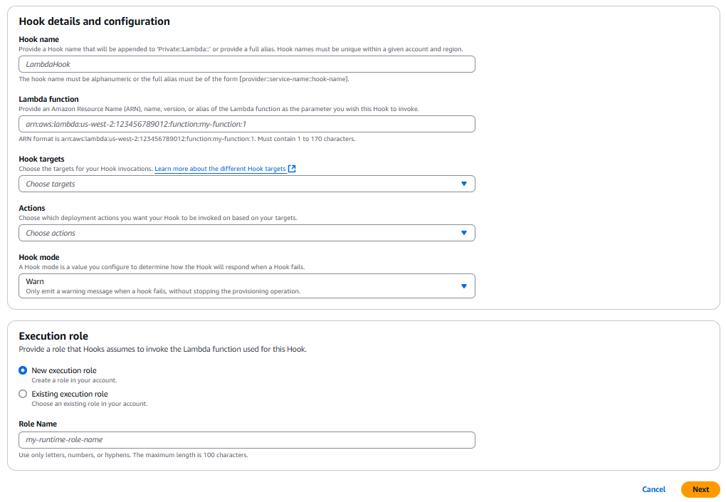


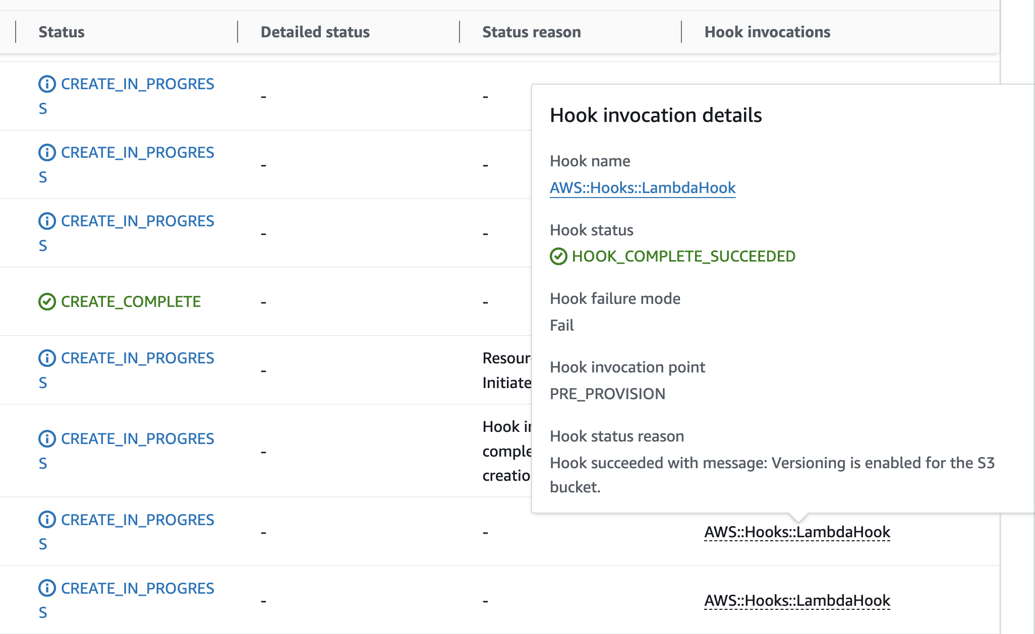

 Stella Hie is a Sr. Product Manager Technical for AWS Infrastructure as Code. She focuses on proactive control and governance space, working on delivering the best experience for customers to use AWS solutions safely. Outside of work, she enjoys hiking, playing piano, and watching live shows.


 Figure 3: CloudFormation’s create stack console wizard
 Figure 4: Real-time CloudFormation in-progress deployment timeline view
 Figure 6: CloudFormation completed deployment timeline view
  Figure 7: CloudFormation deployment timeline view – resource detail popover


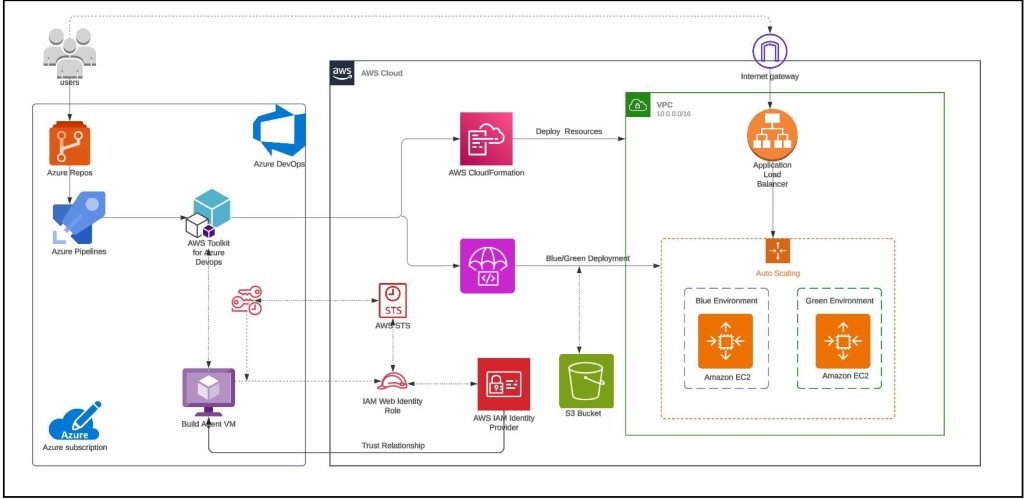
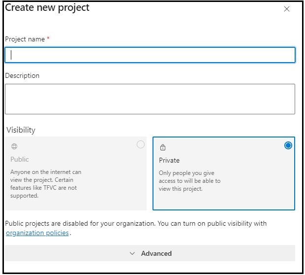
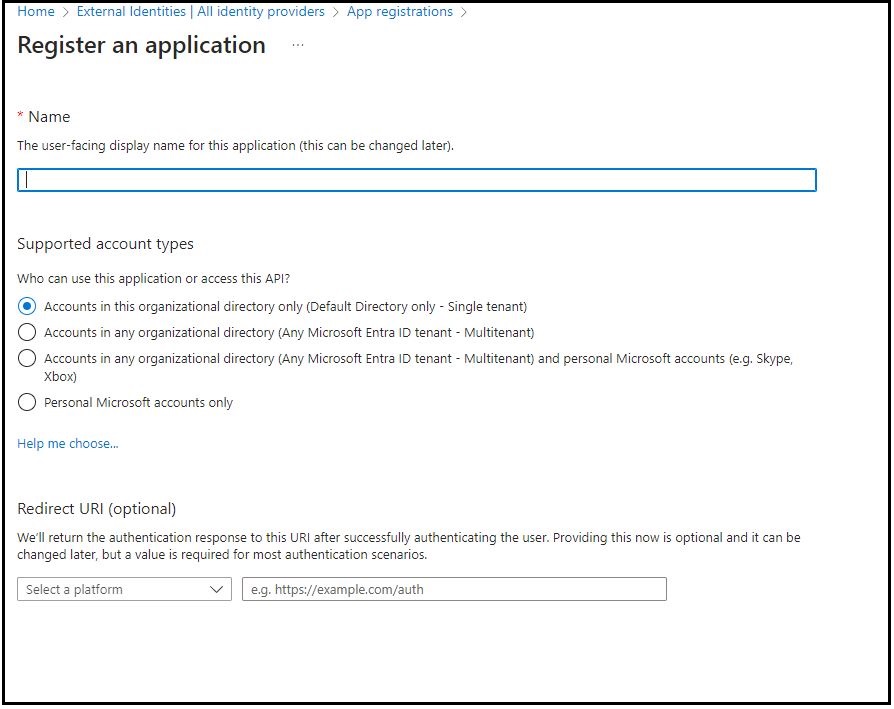
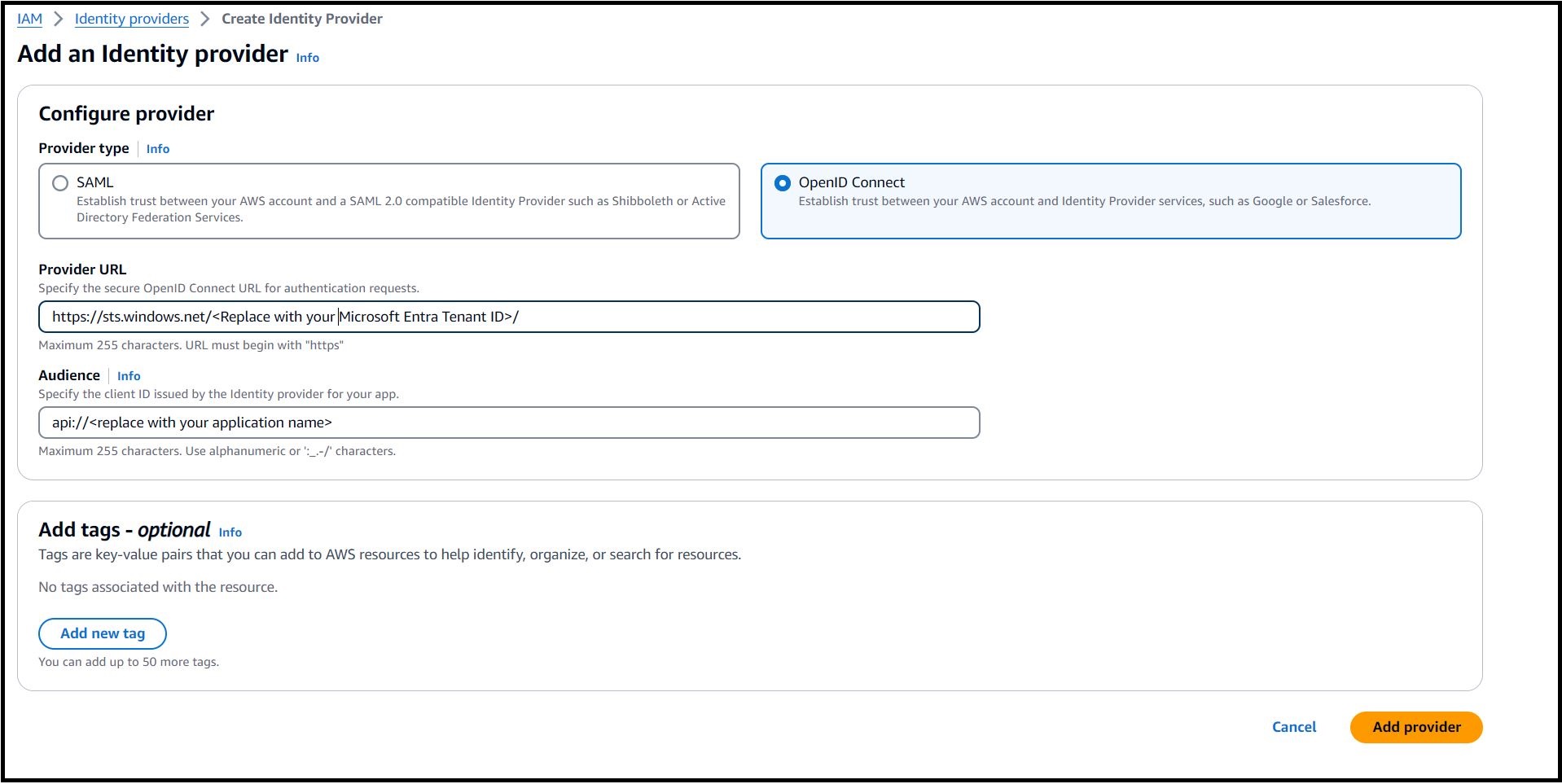
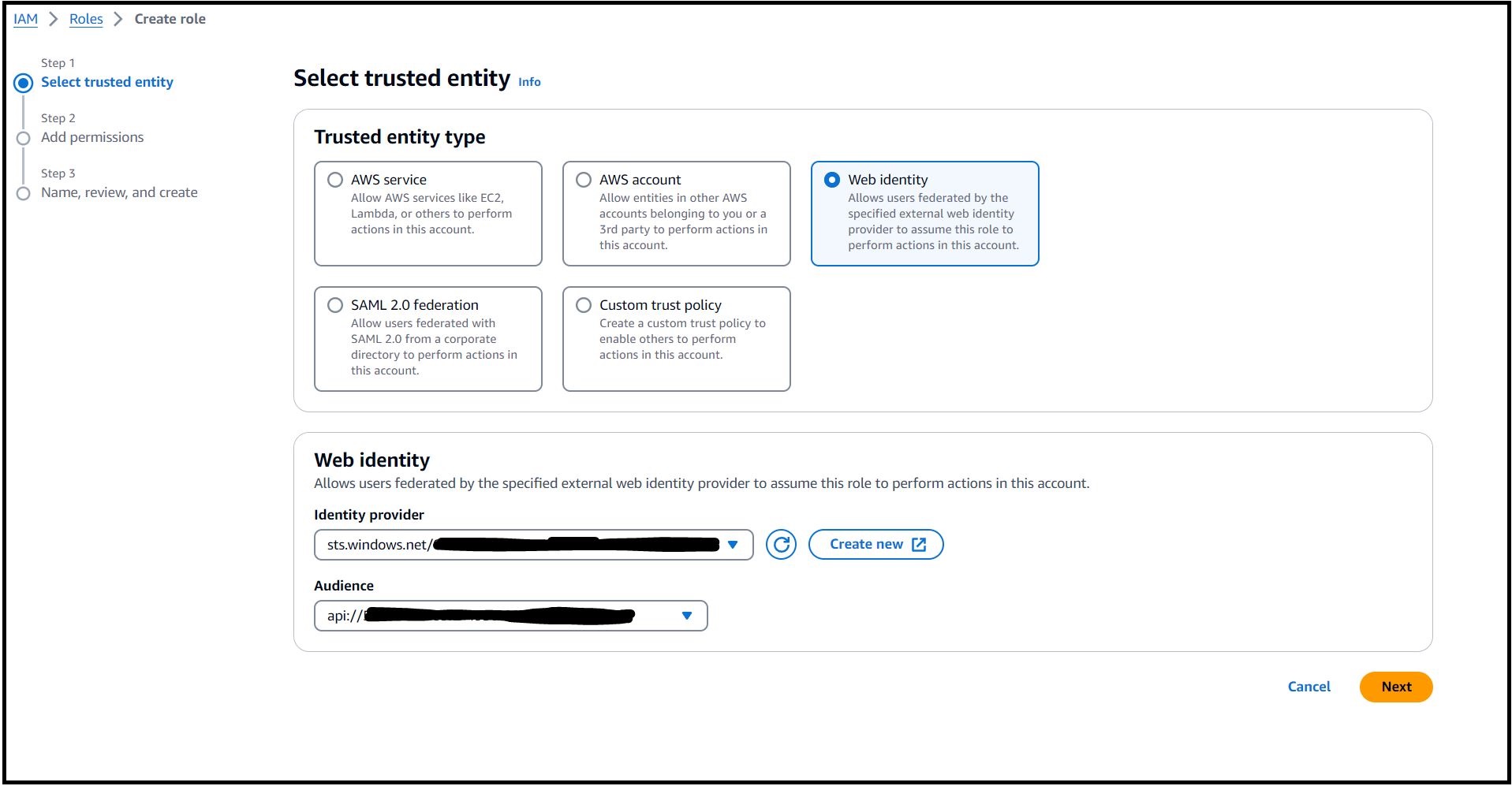
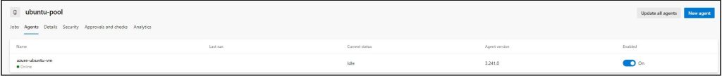
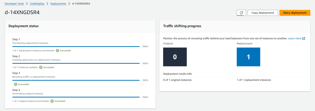


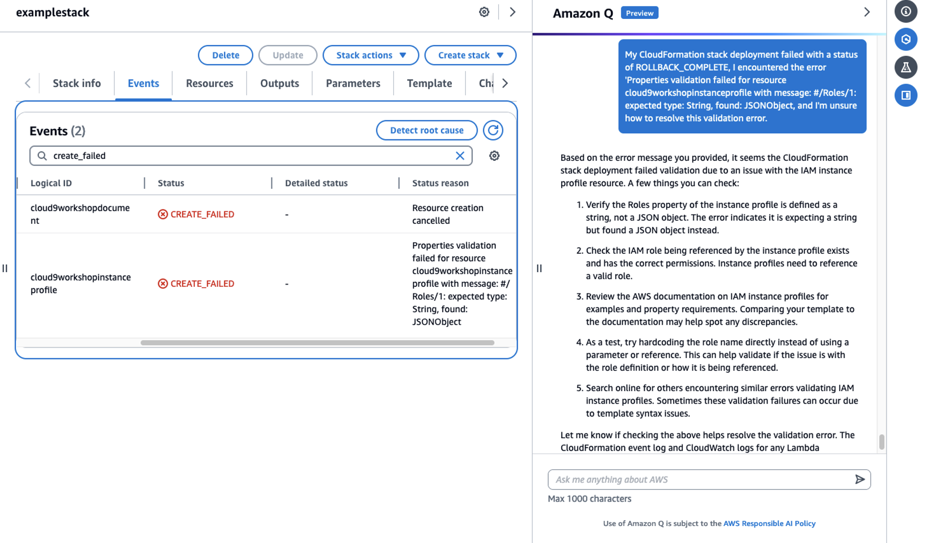
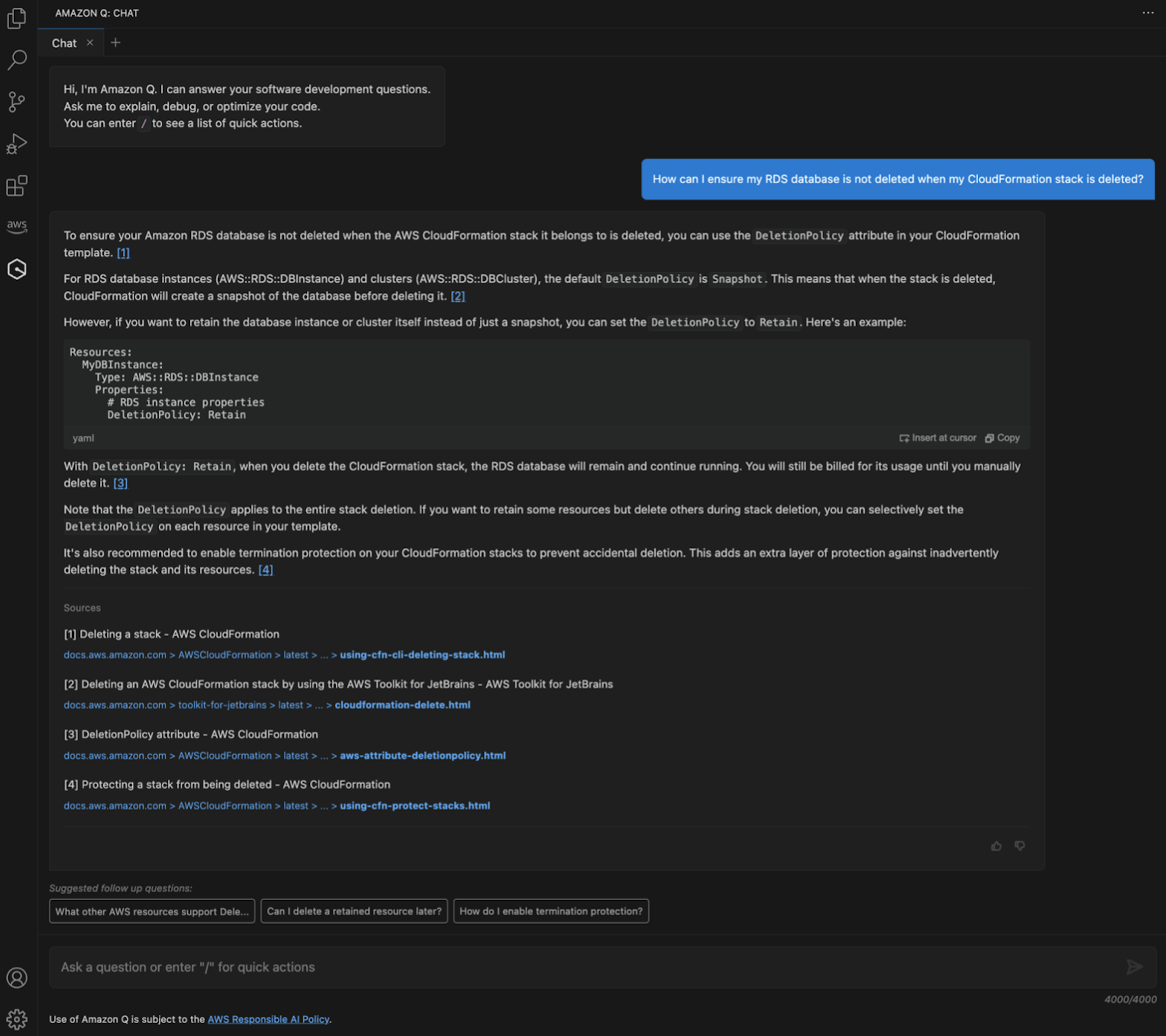


 Build On Generative AI — Now streaming every Thursday, 2:00 PM US PT on


