Post Syndicated from Wei Chen original https://aws.amazon.com/blogs/security/how-to-set-up-federated-single-sign-on-to-aws-using-google-workspace/
Organizations who want to federate their external identity provider (IdP) to AWS will typically do it through AWS Single Sign-On (AWS SSO), AWS Identity and Access Management (IAM), or use both. With AWS SSO, you configure federation once and manage access to all of your AWS accounts centrally. With AWS IAM, you configure federation to each AWS account, and manage access individually for each account. AWS SSO supports identity synchronization through the System for Cross-domain Identity Management (SCIM) v2.0 for several identity providers. For IdPs not currently supported, you can provision users manually. Otherwise, you can choose to federate to AWS from Google Workspace through IAM federation, which this post will cover below.
Google Workspace offers a single sign-on service based off of the Security Assertion Markup Language (SAML) 2.0. Users can use this service to access to your AWS resources by using their existing Google credentials. For users to whom you grant access, they will see an additional SAML app in their Google Workspace console. When your users choose this SAML app, they will be redirected to www.google.com the AWS Management Console.
Solution Overview
In this solution, you will create a SAML identity provider in IAM to establish a trusted communication channel across which user authentication information may be securely passed with your Google IdP in order to permit your Google Workspace users to access the AWS Management Console. You, as the AWS administrator, delegate responsibility for user authentication to a trusted IdP, in this case Google Workspace. Google Workspace leverages SAML 2.0 messages to communicate user authentication information between Google and your AWS account. The information contained within the SAML 2.0 messages allows an IAM role to grant the federated user permissions to sign in to the AWS Management Console and access your AWS resources. The IAM policy attached to the role they select determines which permissions the federated user has in the console.

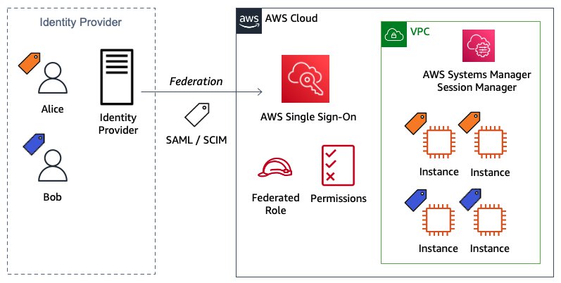
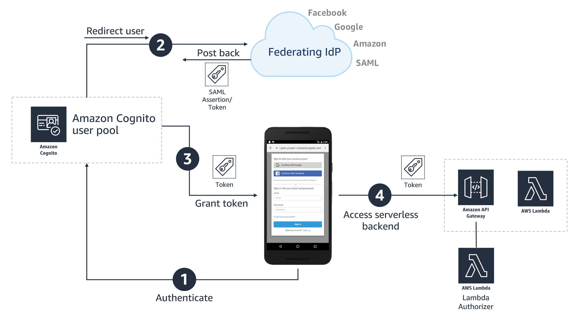
Figure 1: Login process for IAM federation
Figure 1 illustrates the login process for IAM federation. From the federated user’s perspective, this process happens transparently: the user starts at the Google Workspace portal and ends up at the AWS Management Console, without having to supply yet another user name and password.
- The portal verifies the user’s identity in your organization. The user begins by browsing to your organization’s portal and selects the option to go to the AWS Management Console. In your organization, the portal is typically a function of your IdP that handles the exchange of trust between your organization and AWS. In Google Workspace, you navigate to https://myaccount.google.com/ and select the nine dots icon on the top right corner. This will show you a list of apps, one of which will log you in to AWS. This blog post will show you how to configure this custom app.

Figure 2: Google Account page
- The portal verifies the user’s identity in your organization.
- The portal generates a SAML authentication response that includes assertions that identify the user and include attributes about the user. The portal sends this response to the client browser. Although not discussed here, you can also configure your IdP to include a SAML assertion attribute called SessionDuration that specifies how long the console session is valid. You can also configure the IdP to pass attributes as session tags.
- The client browser is redirected to the AWS single sign-on endpoint and posts the SAML assertion.
- The endpoint requests temporary security credentials on behalf of the user, and creates a console sign-in URL that uses those credentials.
- AWS sends the sign-in URL back to the client as a redirect.
- The client browser is redirected to the AWS Management Console. If the SAML authentication response includes attributes that map to multiple IAM roles, the user is first prompted to select the role for accessing the console.

The list below is a high-level view of the specific step-by-step procedures needed to set up federated single sign-on access via Google Workspace.
The setup
Follow these top-level steps to set up federated single sign-on to your AWS resources by using Google Apps:
- Download the Google identity provider (IdP) information.
- Create the IAM SAML identity provider in your AWS account.
- Create roles for your third-party identity provider.
- Assign the user’s role in Google Workspace.
- Set up Google Workspace as a SAML identity provider (IdP) for AWS.
- Test the integration between Google Workspace and AWS IAM.
- Roll out to a wider user base.
Detailed procedures for each of these steps compose the remainder of this blog post.
Step 1. Download the Google identity provider (IdP) information
First, let’s get the SAML metadata that contains essential information to enable your AWS account to authenticate the IdP and locate the necessary communication endpoint locations:
- Log in to the Google Workspace Admin console
- From the Admin console Home page, select Security > Settings > Set up single sign-on (SSO) with Google as SAML Identity Provider (IdP).
Figure 3: Accessing the “single sign-on for SAML applications” setting
- Choose Download Metadata under IdP metadata.
Figure 4: The “SSO with Google as SAML IdP” page


Step 2. Create the IAM SAML identity provider in your account
Now, create an IAM IdP for Google Workspace in order to establish the trust relationship between Google Workspace and your AWS account. The IAM IdP you create is an entity within your AWS account that describes the external IdP service whose users you will configure to assume IAM roles.
- Sign in to the AWS Management Console and open the IAM console at https://console.aws.amazon.com/iam/.
- In the navigation pane, choose Identity providers and then choose Add provider.
- For Configure provider, choose SAML.
- Type a name for the identity provider (such as GoogleWorkspace).
- For Metadata document, select Choose file then specify the SAML metadata document that you downloaded in Step 1–c.
- Verify the information that you have provided. When you are done, choose Add provider.
Figure 5: Adding an Identity provider
- Document the Amazon Resource Name (ARN) by viewing the identity provider you just created in step f. The ARN should looks similar to this:
arn:aws:iam::123456789012:saml-provider/GoogleWorkspace

Step 3. Create roles for your third-party Identity Provider
For users accessing the AWS Management Console, the IAM role that the user assumes allows access to resources within your AWS account. The role is where you define what you allow a federated user to do after they sign in.
- To create an IAM role, go to the AWS IAM console. Select Roles > Create role.
- Choose the SAML 2.0 federation role type.
- For SAML Provider, select the provider which you created in Step 2.
- Choose Allow programmatic and AWS Management Console access to create a role that can be assumed programmatically and from the AWS Management Console.
- Review your SAML 2.0 trust information and then choose Next: Permissions.
Figure 6: Reviewing your SAML 2.0 trust information

GoogleSAMLPowerUserRole:
- For this walkthrough, you are going to create two roles that can be assumed by SAML 2.0 federation. For GoogleSAMLPowerUserRole, you will attach the PowerUserAccess AWS managed policy. This policy provides full access to AWS services and resources, but does not allow management of users and groups. Choose Filter policies, then select AWS managed – job function from the dropdown. This will show a list of AWS managed policies designed around specific job functions.
Figure 7: Selecting the AWS managed job function
- To attach the policy, select PowerUserAccess. Then choose Next: Tags, then Next: Review.
Figure 8: Attaching the PowerUserAccess policy to your role
- Finally, choose Create role to finalize creation of your role.
Figure 9: Creating your role


GoogleSAMLViewOnlyRole
Repeat steps a to g for the GoogleSAMLViewOnlyRole, attaching the ViewOnlyAccess AWS managed policy.
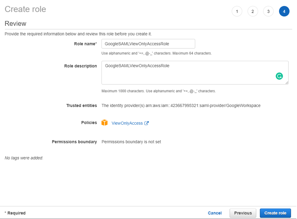
Figure 10: Creating the GoogleSAMLViewOnlyRole
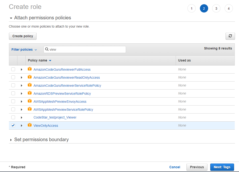
Figure 11: Attaching the ViewOnlyAccess permissions policy
- Document the ARN of both roles. The ARN should be similar to
arn:aws:iam::123456789012:role/GoogleSAMLPowerUserRole and
arn:aws:iam::123456789012:role/GoogleSAMLViewOnlyAccessRole.
Step 4. Assign the user’s role in Google Workspace
Here you will specify the role or roles that this user can assume in AWS.
- Log in to the Google Admin console.
- From the Admin console Home page, go to Directory > Users and select Manage custom attributes from the More dropdown, and choose Add Custom Attribute.
- Configure the custom attribute as follows:
Category: AWS Description: Amazon Web Services Role Mapping For Custom fields, enter the following values:
Name: AssumeRoleWithSaml Info type: Text Visibility: Visible to user and admin InNo. of values: Multi-value - Choose Add. The new category should appear in the Manage user attributes page.
Figure12: Adding the custom attribute
- Navigate to Users, and find the user you want to allow to federate into AWS. Select the user’s name to open their account page, then choose User Information.
- Select on the custom attribute you recently created, named AWS. Add two rows, each of which will include the values you recorded earlier, using the format below for each AssumeRoleWithSaml row.
Row 1:
arn:aws:iam::123456789012:role/GoogleSAMLPowerUserRole,arn:aws:iam:: 123456789012:saml-provider/GoogleWorkspaceRow 2:
arn:aws:iam::123456789012:role/GoogleSAMLViewOnlyAccessRole,arn:aws:iam:: 123456789012:saml-provider/GoogleWorkspaceThe format of the AssumeRoleWithSaml is constructed by using the RoleARN(from Step 3-h) + “,”+ Identity provider ARN (from Step 2-g), this value will be passed as SAML attribute value for attribute with name https://aws.amazon.com/SAML/Attributes/Role. The final result will look similar to below:
Figure 13: Adding the roles that the user can assume


Step 5. Set up Google Workspace as a SAML identity provider (IdP) for AWS
Now you’ll set up the SAML app in your Google Workspace account. This includes adding the SAML attributes that the AWS Management Console expects in order to allow a SAML-based authentication to take place.
Log into the Google Admin console.
- From the Admin console Home page, go to Apps > Web and mobile apps.
- Choose Add custom SAML app from the Add App dropdown.
- Enter AWS Single-Account Access for App name and upload an optional App icon to identify your SAML application, and select Continue.
Figure 14: Naming the custom SAML app and setting the icon
- Fill in the following values:
ACS URL: https://signin.aws.amazon.com/saml Entity ID: urn:amazon:webservices Name ID format: EMAIL Name ID: Basic Information > Primary email Note: Your primary email will become your role’s AWS session name
- Choose CONTINUE.
Figure 15: Adding the custom SAML app
- AWS requires the IdP to issue a SAML assertion with some mandatory attributes (known as claims). The AWS documentation explains how to configure the SAML assertion. In short, you need to create an assertion with the following:
- An attribute of name https://aws.amazon.com/SAML/Attributes/Role. This element contains one or more AttributeValue elements that list the IAM identity provider and role to which the user is mapped by your IdP. The IAM role and IAM identity provider are specified as a comma-delimited pair of ARNs in the same format as the RoleArn and PrincipalArn parameters that are passed to AssumeRoleWithSAML.
- An attribute of name https://aws.amazon.com/SAML/Attributes/RoleSessionName (again, this is just a definition of type, not an actual URL) with a string value. This is the federated user’s role session name in AWS.
- A name identifier (NameId) that is used to identify the subject of a SAML assertion.
Google Directory attributes App attributes AWS > AssumeRoleWithSaml https://aws.amazon.com/SAML/Attributes/Role Basic Information > Primary email https://aws.amazon.com/SAML/Attributes/RoleSessionName
Figure 16: Mapping between Google Directory attributes and SAML attributes
- Choose FINISH and save the mapping.


Step 6. Test the integration between Google Workspace and AWS IAM
- Log into the Google Admin portal.
- From the Admin console Home page, go to Apps > Web and mobile apps.
- Select the Application you created in Step 5-i.
- At the top left, select TEST SAML LOGIN, then choose ALLOW ACCESS within the popup box.
Figure 18: Testing the SAML login
- Select ON for everyone in the Service status section, and choose SAVE. This will allow every user in Google Workspace to see the new SAML custom app.
Figure 19: Saving the custom app settings
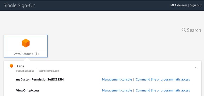
- Now navigate to Web and mobile apps and choose TEST SAML LOGIN again. Amazon Web Services should open in a separate tab and display two roles for users to choose from:
FIgure 20: Testing SAML login again
Figure 21: Selecting the IAM role you wish to assume for console access
- Select the desired role and select Sign in.
- You should now be redirected to AWS Management Console home page.
- Google workspace users should now be able to access the AWS application from their workspace:

Figure 22: Viewing the AWS custom app


Conclusion
By following the steps in this blog post, you’ve configured your Google Workspace directory and AWS accounts to allow SAML-based federated sign-on for selected Google Workspace users. Using this over IAM users helps centralize identity management, making it easier to adopt a multi-account strategy.
If you have feedback about this post, submit comments in the Comments section below. If you have questions about this post, contact AWS Support.
Want more AWS Security news? Follow us on Twitter.


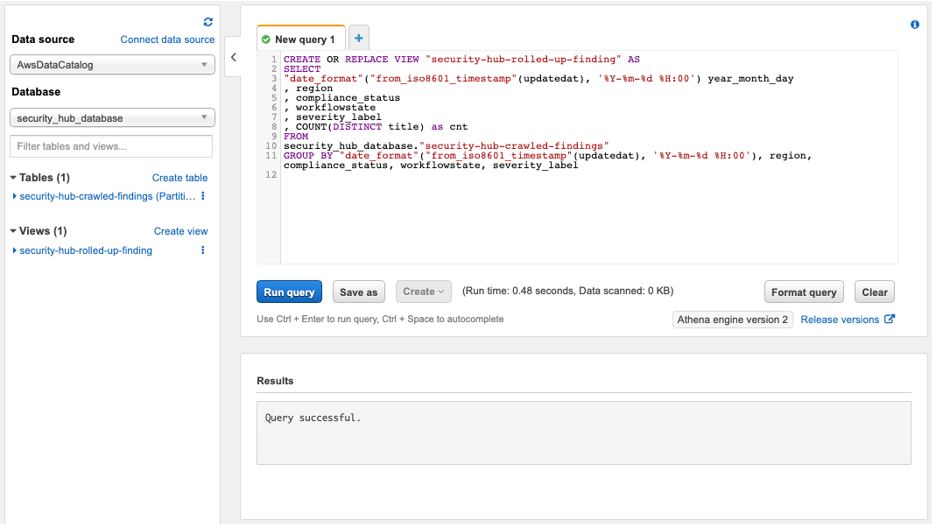


 Once you create the data source Quicksight lists all the views and tables available under the specified database (in our case it is:- due_eventdb). Select the email_all_events view as data source.
 Select the event data location for analysis. There are mainly two options available which are a/ Import to Spice quicker analysis b/ Directly query your data. Please select the preferred options and then click on “visualize the data”.
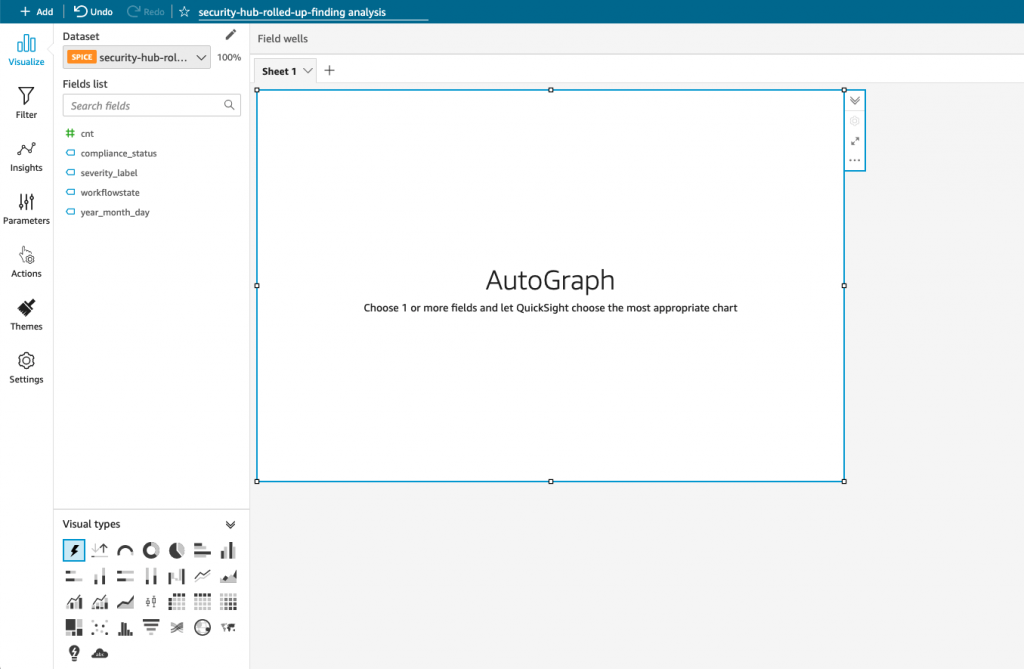
 Now that you have selected a data source, you will be taken to a blank quick sight canvas (Blank analysis page) as shown in the following Image, please drag and drop what
  As part of this blog, we have displayed how to create some simple analysis graphs to visualize the engagement events.
 Select all the event dimensions that you want to put it as part of the Table in X axis. Amazon Quicksight table can be extended to show as many as tables columns, this completely depends upon the business requirement how much data marketers want to visualize.
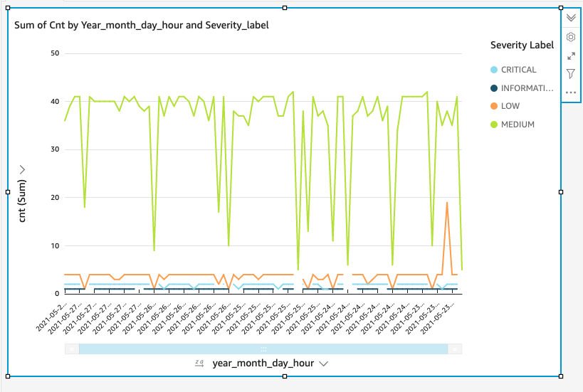
 To create a Quicksight dashboards from the Quicksight analysis click Share menu option at the top right corner then select publish dashboard”. Provide required dashboard name while publishing the dashboard”. Same dashboard can be shared with multiple audiences in the Organization.
 Following is the final version of the dashboard. As mentioned above Quicksight dashboards can be shared with other stakeholders and also complete dashboard can be exported as excel sheet.


![Architecture Diagram showing the service “Test” using the container “brickwall-maker” with a desired count of two. The two ECS Task’s vended metrics are then processed by CloudWatch Container Insights. Both, CloudWatch Container Insights and CloudTrail, are ingested by Amazon DevOps Guru which then makes detected insights available to the user. [Image: DevOpsGuruBlog1.png]V1: DevOpsGuruBlog1.drawio (https://api.quip-amazon.com/2/blob/fbe9AAT37Ge/LdkTqbmlZ8uNj7A44pZbnw?name=DevOpsGuruBlog1.drawio&s=cVbmAWsXnynz) V2: DevOpsGuruBlog1.drawio (https://api.quip-amazon.com/2/blob/fbe9AAT37Ge/SvsNTJLEJOHHBls_kV7EwA?name=DevOpsGuruBlog1.drawio&s=cVbmAWsXnynz) V3: DevOpsGuruBlog1.drawio (https://api.quip-amazon.com/2/blob/fbe9AAT37Ge/DqKTxtQvmOLrzM3KcF_oTg?name=DevOpsGuruBlog1.drawio&s=cVbmAWsXnynz)](https://d2908q01vomqb2.cloudfront.net/7719a1c782a1ba91c031a682a0a2f8658209adbf/2021/10/29/DevOpsGuruBlog1-1-1.png)