Post Syndicated from Matt Duda original https://aws.amazon.com/blogs/security/how-to-automate-forensic-disk-collection-in-aws/
In this blog post you’ll learn about a hands-on solution you can use for automated disk collection across multiple AWS accounts. This solution will help your incident response team set up an automation workflow to capture the disk evidence they need to analyze to determine scope and impact of potential security incidents. This post includes AWS CloudFormation templates and all of the required AWS Lambda functions, so you can deploy this solution in your own environment. This post focuses primarily on two sources as the origination of the evidence collection workflow: AWS Security Hub and Amazon GuardDuty.
Why is automating forensic disk collection important?
AWS offers unique scaling capabilities in our compute environments. As you begin to increase your number of compute instances across multiple AWS accounts or organizations, you will find operational aspects of your business that must also scale. One of these critical operational tasks is the ability to quickly gather forensically sound disk and memory evidence during a security event.
During a security event, your incident response (IR) team must be able to collect and analyze evidence quickly while maintaining accuracy for the time period surrounding the event. It is both challenging and time consuming for the IR team to manually collect all of the relevant evidence in a cloud environment, across a large number of instances and accounts. Additionally, manual collection requires time that could otherwise be spent analyzing and responding to an event. Every role assumption, every console click, and every manual trigger required by the IR team, adds time for an attacker to continue to work through systems to meet their objectives.
Indicators of compromise (IoCs) are pieces of data that IR teams often use to identify potential suspicious activity within networks that might need further investigation. These IoCs can include file hashes, domains, IP addresses, or user agent strings. IoCs are used by services such as GuardDuty to help you discover potentially malicious activity in your accounts. For example, when you are alerted that an Amazon Elastic Compute Cloud (Amazon EC2) instance contains one or more IoCs, your IR team must gather a point-in-time copy of relevant forensic data to determine the root cause, and evaluate the likelihood that the finding requires action. This process involves gathering snapshots of any and all attached volumes, a live dump of the system’s memory, a capture of the instance metadata, and any logs that relate to the instance. These sources help your IR team to identify next steps and work towards a root cause.
It is important to take a point-in-time snapshot of an instance as close in time to the incident as possible. If there is a delay in capturing the snapshot, it can alter or make evidence unusable because the data has changed or been deleted. To take this snapshot quickly, you need a way to automate the collection and delivery of potentially hundreds of disk images while ensuring each snapshot is collected in the same way and without creating a bottleneck in the pipeline that could reduce the integrity of the evidence. In this blog post, I explain the details of the automated disk collection workflow, and explain why you might make different design decisions. You can download the solutions in CloudFormation, so that you can deploy this solution and get started on your own forensic automation workflows.
AWS Security Hub provides an aggregated view of security findings across AWS accounts, including findings produced by GuardDuty, when enabled. Security Hub also provides you with the ability to ingest custom or third-party findings, which makes it an excellent starting place for automation. This blog post uses EC2 GuardDuty findings collected into Security Hub as the example, but you can also use the same process to include custom detection events, or alerts from partner solutions such as CrowdStrike, McAfee, Sophos, Symantec, or others.
Infrastructure overview
The workflow described in this post automates the tasks that an IR team commonly takes during the course of an investigation.
Overview of disk collection workflow
The high-level disk collection workflow steps are as follows:
- Create a snapshot of each Amazon Elastic Block Store (Amazon EBS) volume attached to suspected instances.
- Create a folder in the Amazon Simple Storage Service (Amazon S3) evidence bucket with the original event data.
- Launch one Amazon EC2 instance per EBS volume, to be used in streaming a bit-for-bit copy of the EBS snapshot volume. These EC2 instances are launched without SSH key pairs, to help prevent any unintentional evidence corruption and to ensure consistent processing without user interaction. The EC2 instances use third-party tools dc3dd and incrond to trigger and process volumes.
- Write all logs from the workflow and instances to Amazon CloudWatch Logs log groups, for audit purposes.
- Include all EBS volumes in the S3 evidence bucket as raw image files (.dd), with the metadata from the automated capture process, as well as hashes for validation and verification.
Overview of AWS services used in the workflow
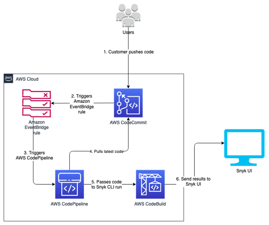
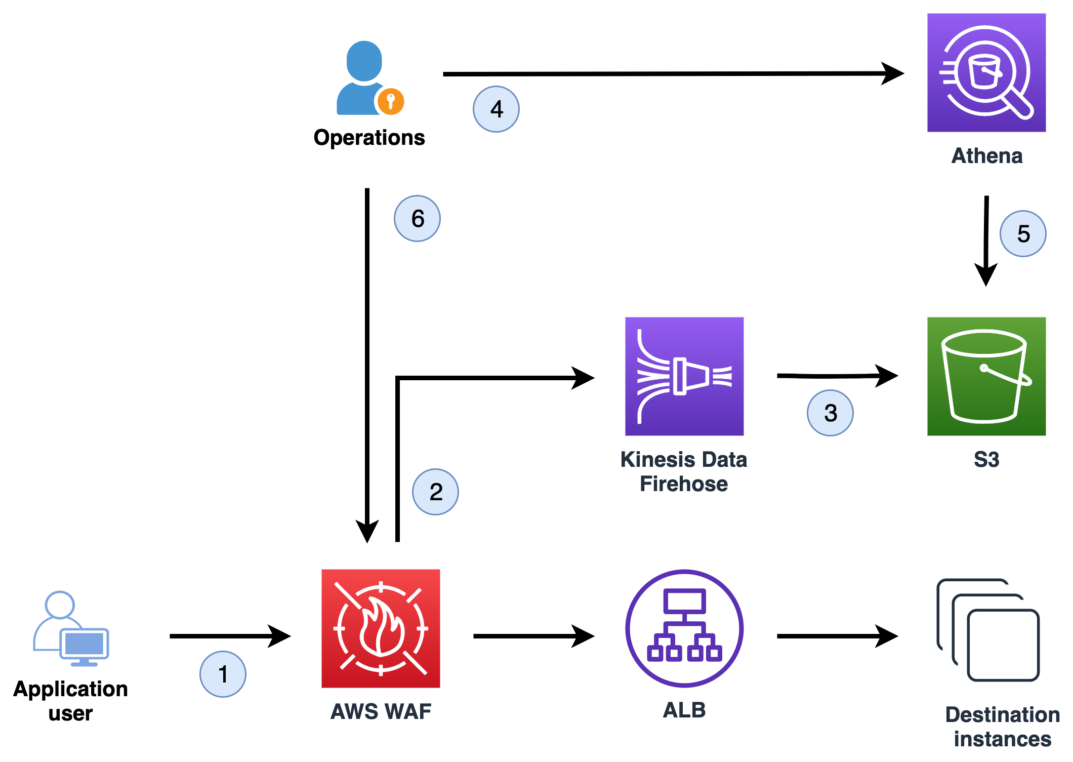
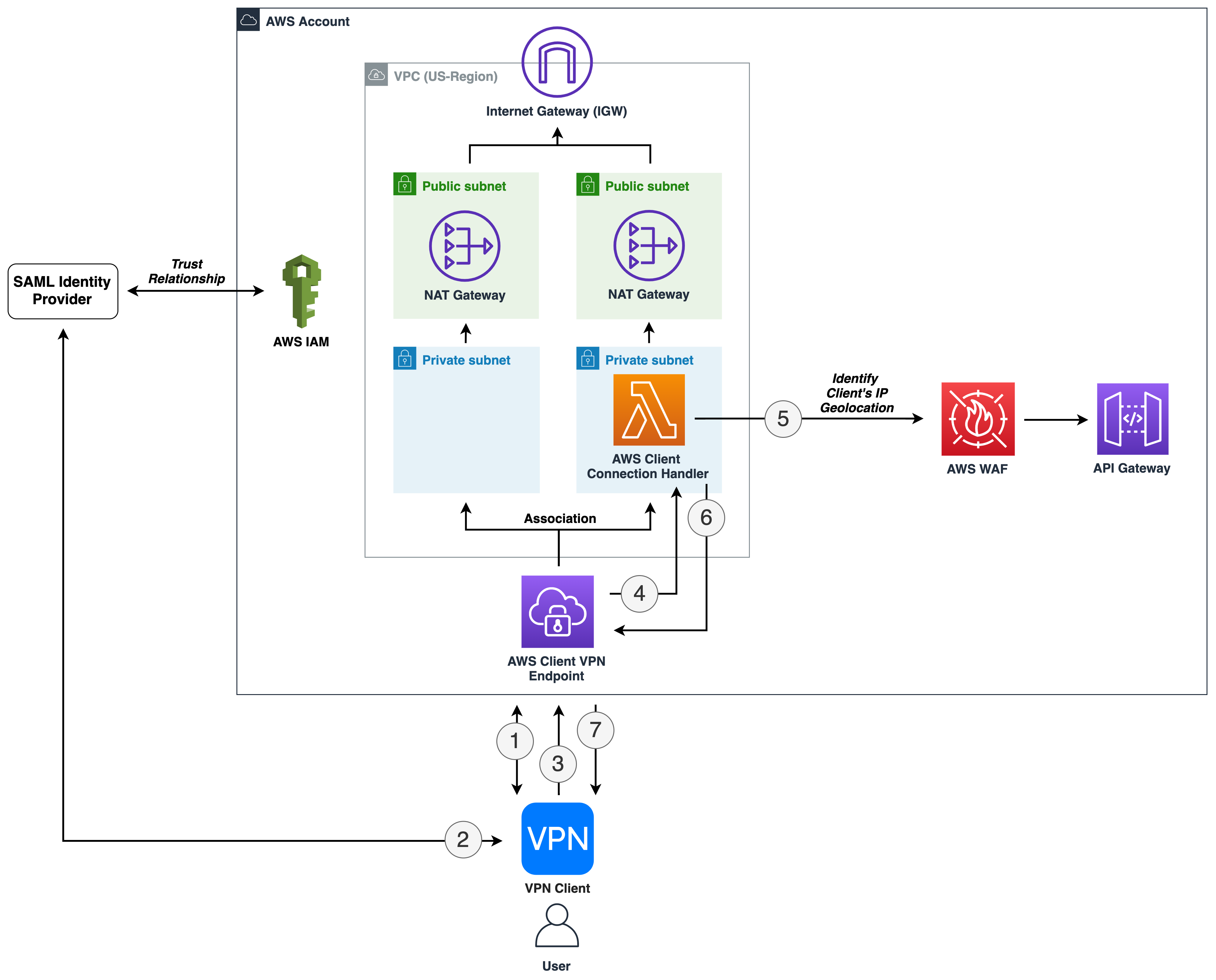
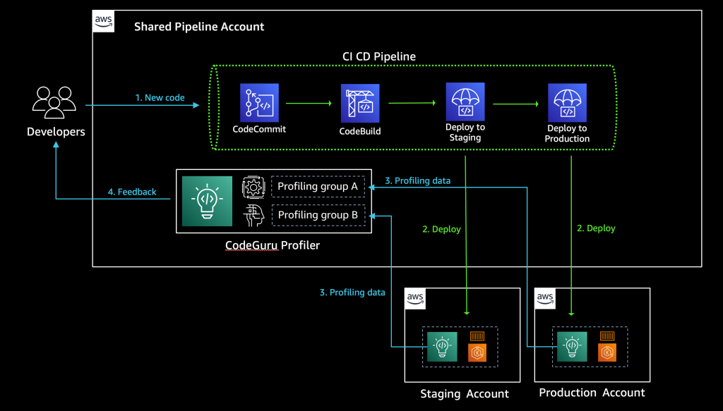
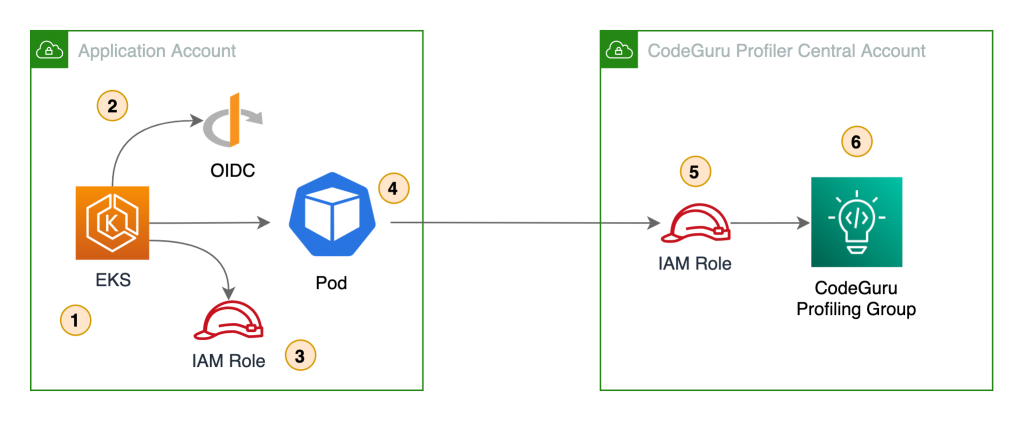
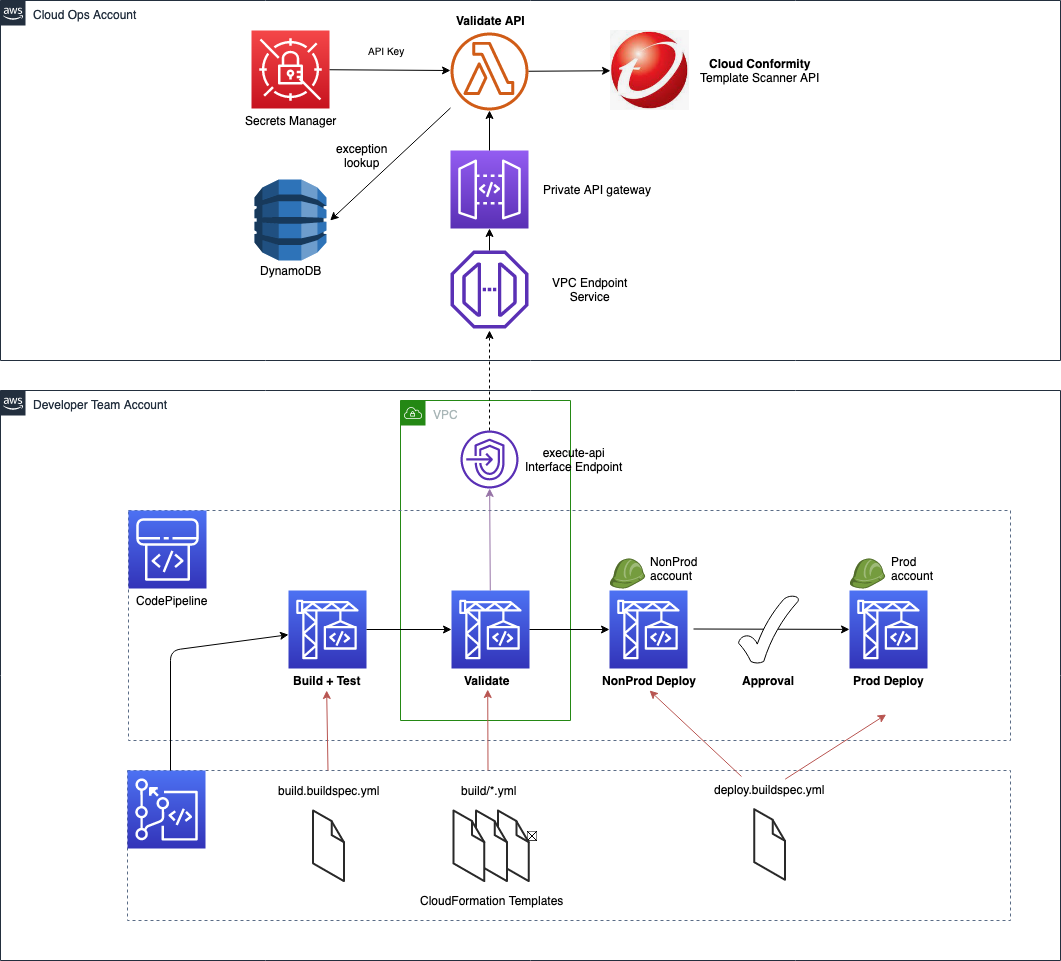
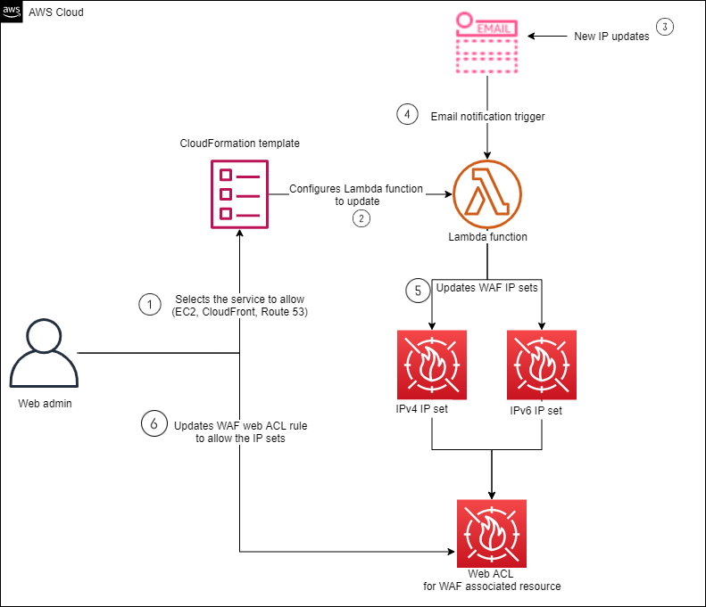
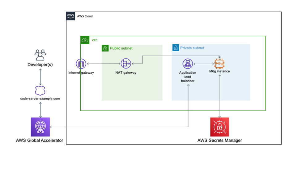
Another way of looking at this high-level workflow is from the service perspective, as shown in Figure 1.
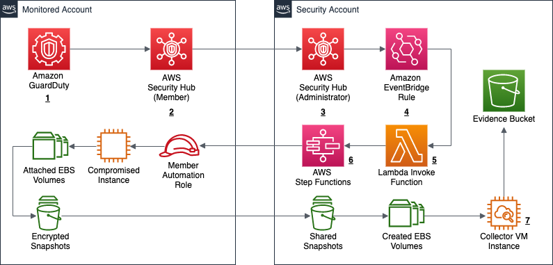
Figure 1: Service workflow for forensic disk collection
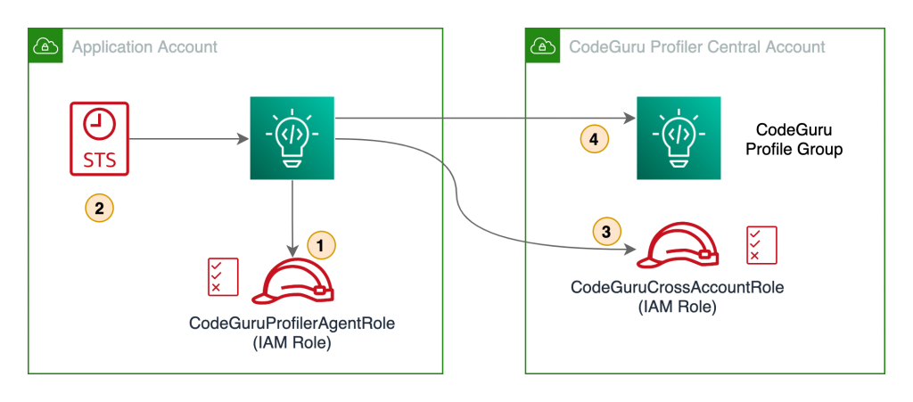
The workflow in Figure 1 shows the following steps:
- A GuardDuty finding is triggered for an instance in a monitored account. This example focuses on a GuardDuty finding, but the initial detection source can also be a custom event, or an event from a third party.
- The Security Hub service in the monitored account receives the GuardDuty finding, and forwards it to the Security Hub service in the security account.
- The Security Hub service in the security account receives the monitored account’s finding.
- The Security Hub service creates an event over Amazon EventBridge for the GuardDuty findings, which is then caught by an EventBridge rule to forward to the DiskForensicsInvoke Lambda function. The following is the example event rule, which is included in the deployment. This example can be expanded or reduced to fit your use-case. By default, the example is set to disabled in CloudFormation. When you are ready to use the automation, you will need to enable it.
- The DiskForensicsInvoke Lambda function receives the event from EventBridge, formats the event, and provides the formatted event as input to AWS Step Functions workflow.
- The DiskForensicStepFunction workflow includes ten Lambda functions, from initial snapshot to streaming the evidence to the S3 bucket. After the Step Functions workflow enters the CopySnapshot state, it converts to a map state. This allows the workflow to have one thread per volume submitted, and ensures that each volume will be placed in the evidence bucket as quickly as possible without needing to wait for other steps to complete.

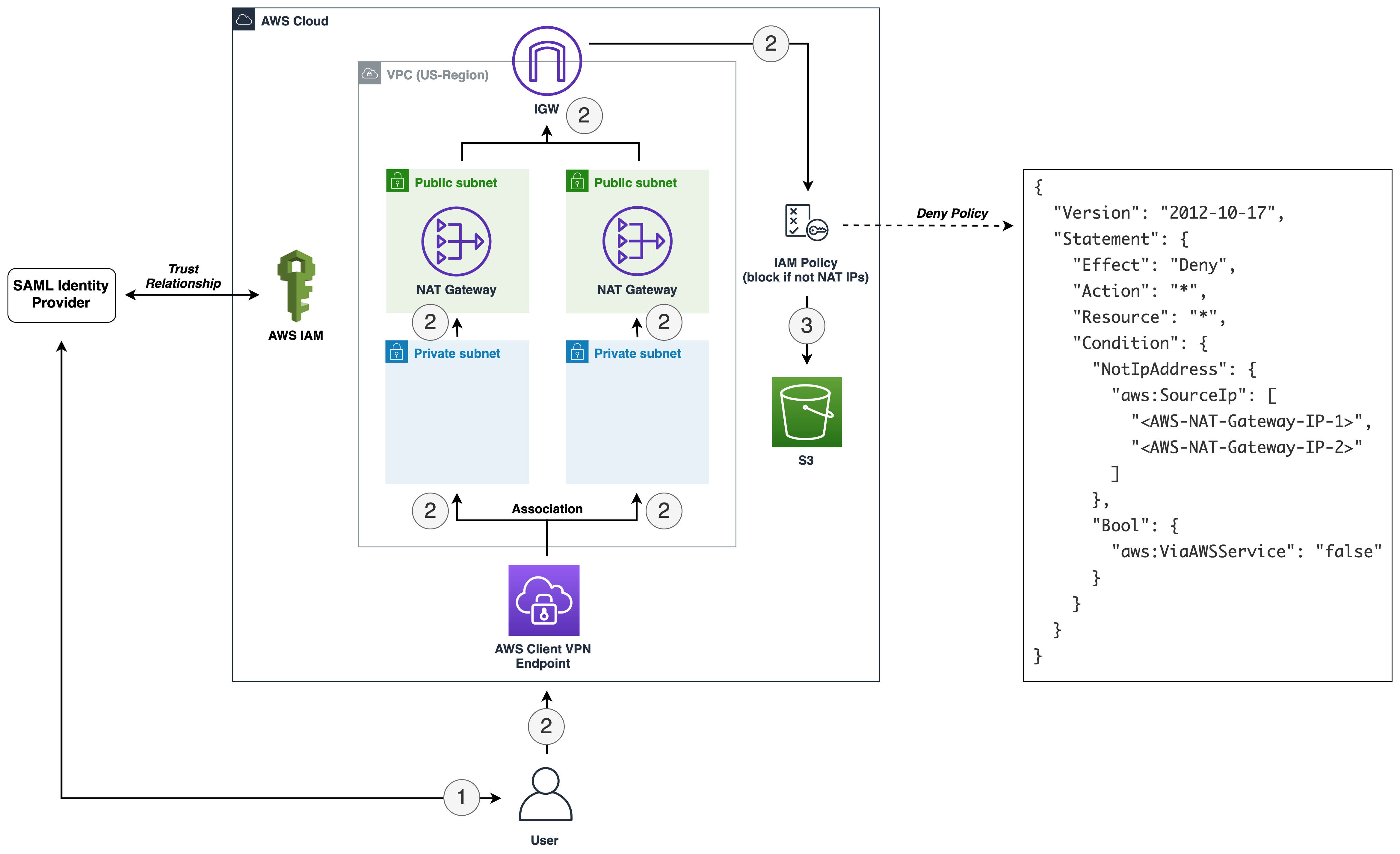
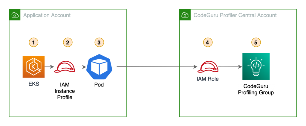
Figure 2: Forensic disk collection Step Function workflow
As shown in Figure 2, the following are the embedded Lambda functions in the DiskForensicStepFunction workflow:
- CreateSnapshot – This function creates the initial snapshots for each EBS volume attached to the instance in question. It also records instance metadata that is included with the snapshot data for each EBS volume.
Required Environmental Variables: ROLE_NAME, EVIDENCE_BUCKET, LOG_GROUP - CheckSnapshot – This function checks to see if the snapshots from the previous step are completed. If not, the function retries with an exponential backoff.
Required Environmental Variable: ROLE_NAME - CopySnapshot – This function copies the initial snapshot and ensures that it is using the forensics AWS Key Management Service (AWS KMS) key. This key is stored in the security account and will be used throughout the remainder of the process.
Required Environmental Variables: ROLE_NAME, KMS_KEY - CheckCopySnapshot – This function checks to see if the snapshot from the previous step is completed. If not, the function retries with exponential backoff.
Required Environmental Variable: ROLE_NAME - ShareSnapshot – This function takes the copied snapshot using the forensics KMS key, and shares it with the security account.
Required Environmental Variables: ROLE_NAME, SECURITY_ACCOUNT - FinalCopySnapshot – This function copies the shared snapshot into the security account, as the original shared snapshot is still owned by the monitored account. This ensures that a copy is available, in case it has to be referenced for additional processing later.
Required Environmental Variable: KMS_KEY - FinalCheckSnapshot – This function checks to see if the snapshot from the previous step is completed. If not, the function fails and it retries with an exponential backoff.
- CreateVolume – This function creates an EBS Magnetic volume from the snapshot in the previous step. These volumes created use magnetic disks, because they are required for consistent hash results from the dc3dd process. This volume cannot use a solid state drive (SSD), because the hash would be different each time. If the EBS Magnetic volume size is greater than or equal to 500GB, then Amazon EBS switches from using standard EBS Magnetic volumes to Throughput Optimized HDD (st1) volumes.
Required Environmental Variables: KMS_KEY, SUPPORTED_AZS - RunInstance – This function launches one EC2 instance per volume, to be used in streaming the volume to the S3 bucket. The AMI passed by the environmental variable needs to be created using the provided Amazon EC2 Image Builder pipeline before deploying the environment. This function also passes some user data to the instance, artifact bucket, source volume name, and the incidentID. This information is used by the instance when placing the evidence into the S3 bucket.
Required Environmental Variables: AMI_ID, INSTANCE_PROFILE_NAME, VPC_ID, SECURITY_GROUP - CreateInstanceWait – This function creates a 30-second wait, to allow the instance some additional time to spin up.
- MountForensicVolume – This function checks the CloudWatch log group ForensicDiskReadiness, to see that the incrond service is running on the instance. If the incrond service is running, the function attaches the volume to the instance and then writes the final logs to the S3 bucket and CloudWatch Logs.
Required Environmental Variable: LOG_GROUP
- CreateSnapshot – This function creates the initial snapshots for each EBS volume attached to the instance in question. It also records instance metadata that is included with the snapshot data for each EBS volume.
- The instance that is created has pre-built tools and scripts on it from the template below using Image Builder. This instance uses the incrond tool to monitor /dev/disk/by-label for new devices being attached to the instance. After the MountForensicVolume Lambda function attaches the volume to the instance, a file is created in the /dev/disk/by-label directory for the attached volume. The incrond daemon starts the orchestrator script, which calls the collector script. The collector script uses the dc3dd tool to stream the bit-for-bit copy of the volume to S3. After the copy has completed, the image shuts down and is terminated. All logs from the process are sent to the S3 bucket and CloudWatch Logs.

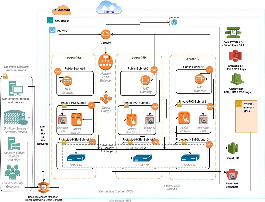
The solution provided in the post includes the CloudFormation templates you need to get started, except for creation the initial EventBridge rule (which is provided in step 4 of the previous section). The solution includes an isolated VPC, subnets, security groups, roles, and more. The VPC provided does not provide any egress through an internet gateway or NAT gateway, and that is the recommended solution. The only connectivity provided is through the S3 gateway VPC endpoint and the CloudWatch Logs interface VPC endpoint (also deployed in the template).
Deploy the CloudFormation templates
To implement the solution outlined in this post, you need to deploy three separate AWS CloudFormation templates in the order described in this section.
diskForensicImageBuilder (security account)
First, you deploy diskForensicImageBuilder in the security account. This template contains the resources and AMIs needed to create and run the Image Builder pipeline that is required to build the collector VM. This pipeline installs the required binaries, and scripts, and updates the system.
Note: diskForensicImageBuilder is configured to use the default VPC and security group. If you have added restrictions or deleted your default VPC, you will need to modify the template.
To deploy the diskForensicImageBuilder template
- To open the AWS CloudFormation console pre-loaded with the template, choose the following Launch Stack button.

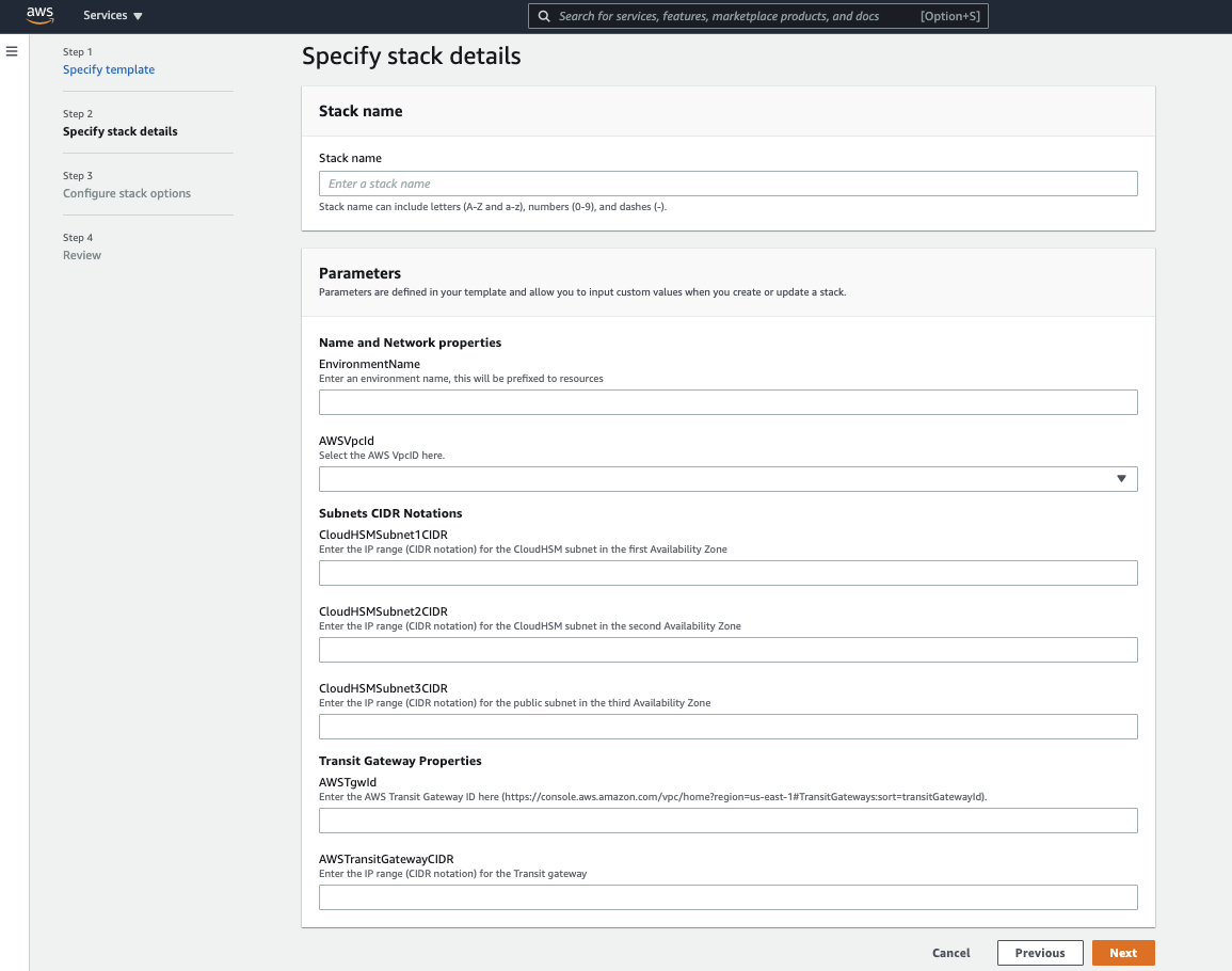
- In the AWS CloudFormation console, on the Specify Details page, enter a name for the stack.
- Leave all default settings in place, and choose Next to configure the stack options.
- Choose Next to review and scroll to the bottom of the page. Select the check box under the Capabilities section, next to of the acknowledgement:
- I acknowledge that AWS CloudFormation might create IAM resources with custom names.
- Choose Create Stack.
- After the Image Builder pipeline has been created, on the Image pipelines page, choose Actions and select Run pipeline to manually run the pipeline to create the base AMI.

Figure 3: Run the new Image Builder pipeline


diskForensics (security account)
Second, you deploy diskForensics in the security account. This is a nested CloudFormation stack containing four CloudFormation templates. The four CloudFormation templates are as follows:
- forensicResources – This stack holds all of the foundation for the solution, including the VPC and networking components, the S3 evidence bucket, CloudWatch log groups, and collectorVM instance profile.

Figure 4: Forensics VPC
- forensicFunctions – This stack contains all of the Lambda functions referenced in the Step Functions workflow as well as the role used by the Lambda functions.
- forensicStepFunction – This stack contains the Step Functions code, the role used by the Step Functions service, and the CloudWatch log group used by the service. It also contains an Amazon Simple Notification Service (SNS) topic used to alert on pipeline failure.
- forensicStepFunctionInvoke – This stack contains the DiskForensicsInvoke Lambda function and the role used by that Lambda function that allows it to call the Step Function workflow.

Note: You need to have the following required variables to continue:
- ArtifactBucketName
- ORGID
- ForensicsAMI
If your accounts are not using AWS Organizations, you can use a dummy string for now. It adds a condition statement to the forensics KMS key that you can update or remove later.
To deploy the diskForensics stack
- To open the AWS CloudFormation console pre-loaded with the template, choose the following Launch Stack button.
- In the AWS CloudFormation console, on the Specify Details page, enter a name for the stack.
- For the ORGID field, enter the AWS Organizations ID.
Note: If you are not using AWS organizations, leave the default string. If you are deploying as multi-account without AWS Organizations, you will need to update the KMS key policy to remove the principalOrgID condition statements, and add the correct principals.
- For the ArtifactBucketName field, enter the S3 bucket name you would like to use for your forensic artifacts.
Important: The ArtifactBucketName must be a globally unique name.
- For the ForensicsAMI field, enter the AMI ID for the image that was created by Image Builder.
- For the example in this post, leave the default values for all other fields. Customizing these fields allows you to customize this code example for your own purposes.
- Choose Next to configure the stack options and leave all default settings in place.
- Choose Next to review and scroll to the bottom of the page. Select the two check boxes under the Capabilities section, next to each of the acknowledgements:
- I acknowledge that AWS CloudFormation might create IAM resources with custom names.
- I acknowledge that AWS CloudFormation might require the following capability: CAPABILITY_AUTO_EXPAND.
- Choose Create Stack.
- After the stack has completed provisioning, subscribe to the Amazon SNS topic to receive pipeline alerts.
diskMember (each monitored account)
Third, you deploy diskMember in each monitored account. This stack contains the role and policy that the automation workflow needs to assume, so that it can create the initial snapshots and share the snapshot with the security account. If you are deploying this solution in a single account, you deploy diskMember in the security account.
Important: Ensure that all KMS keys that could be used to encrypt EBS volumes in each monitored account grant this role the ability to CreateGrant, Encrypt, Decrypt, ReEncrypt*, GenerateDataKey*, and Describe key. The default policy grants the permissions in AWS Identity and Access Management (IAM), but any restrictive resource policies could block the ability to create the initial snapshot and decrypt the snapshot when making the copy.
To deploy the diskMember stack
- To open the AWS CloudFormation console pre-loaded with the template, choose the following Launch Stack button.
If deploying across multiple accounts, consider using AWS CloudFormation StackSets for simplified multi-account deployment. - In the AWS CloudFormation console, on the Specify Details page, enter a name for the stack.
- For the MasterAccountNum field, enter the account number for your security administrator account.
- Choose Next to configure the stack options and leave all default settings in place.
- Choose Next to review and scroll to the bottom of the page. Select the check box under the Capabilities section, next to the acknowledgement:
- I acknowledge that AWS CloudFormation might create IAM resources with custom names.
- Choose Create Stack.
Test the solution
Next, you can try this solution with an event sample to start the workflow.
To initiate a test run
- Copy the following example GuardDuty event. The example uses the AWS Region us-east-1, but you can update the example to use another Region. Be sure to replace the account ID 0123456789012 with the account number of your monitored account, and replace the instance ID i-99999999 with the instance ID you would like to capture.
- Navigate to the DiskForensicsInvoke Lambda function and add the GuardDuty event as a test event.
- Choose Test. You should see a success for the invocation.
- Navigate to the Step Functions workflow to monitor its progress. When the instances have terminated, all of the artifacts should be in the S3 bucket with additional logs in CloudWatch Logs.
Expected outputs
The forensic disk collection pipeline maintains logs of the actions throughout the process, and uploads the final artifacts to the S3 artifact bucket and CloudWatch Logs. This enables security teams to send forensic collection logs to log aggregation tools or service management tools for additional integrations. The expected outputs of the solution are detailed in the following sections, organized by destination.
S3 artifact outputs
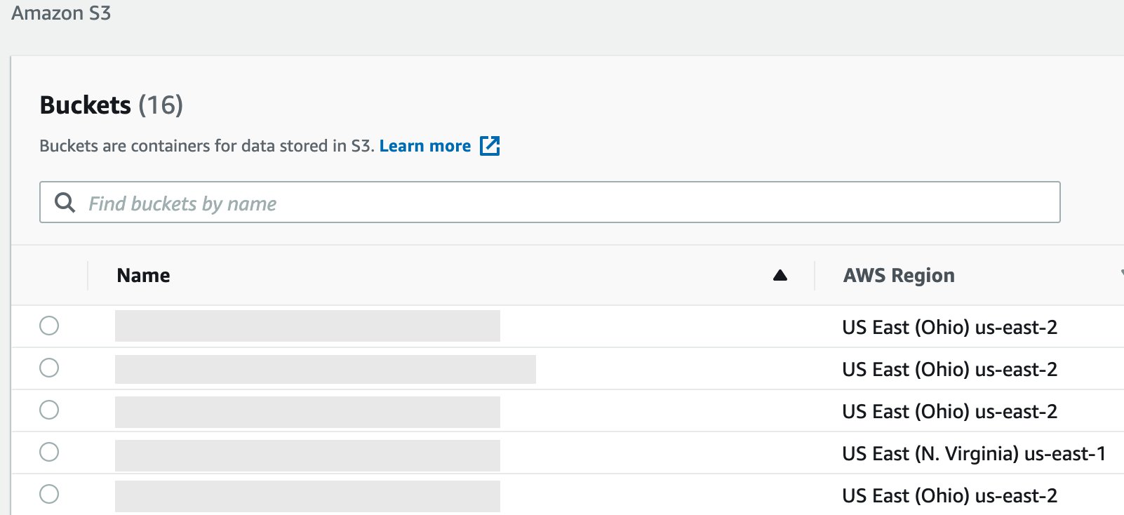
The S3 artifact bucket is the final destination for all logs and the raw disk images. For each security incident that triggers the Step Functions workflow, a new folder will be created with the name of the IncidentID. Included in this folder will be the JSON file that triggered the capture operation, the image (dd) files for the volumes, the capture log, and the resources associated with the capture operation, as shown in Figure 5.
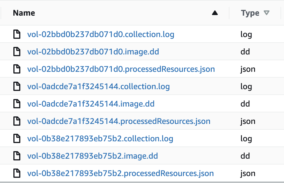
Figure 5: Forensic artifacts in the S3 bucket
Forensic Disk Audit log group
The Forensic Disk Audit CloudWatch log group contains a log of where the Step Functions workflow was after creating the initial snapshots in the CreateSnapshot Lambda function. This includes the high-level finding information, as well as the metadata for each snapshot. Also included in this log group is the completed data around each completed disk collection operation, including all associated resources and the location of the forensic evidence in the S3 bucket. The following event is an example log demonstrating a completed capture. Notice all of the metadata provided under captured snapshots. Be sure to update the example to use the correct AWS Region. Replace the account ID 0123456789012 with the account number of your monitored account, and replace the instance ID i-99999999 with the instance ID you would like to capture.
Forensic Disk Capture log group
The Forensic Disk Capture CloudWatch log group contains the logs from the EC2Collector VM. These logs detail the operations taken by the instance, which include when the dc3dd command was executed, what the transfer speed was to the S3 bucket, what the hash of the volume was, and how long the total operation took to complete. The log example in Figure 6 shows the output of the disk capture on the collector instance.
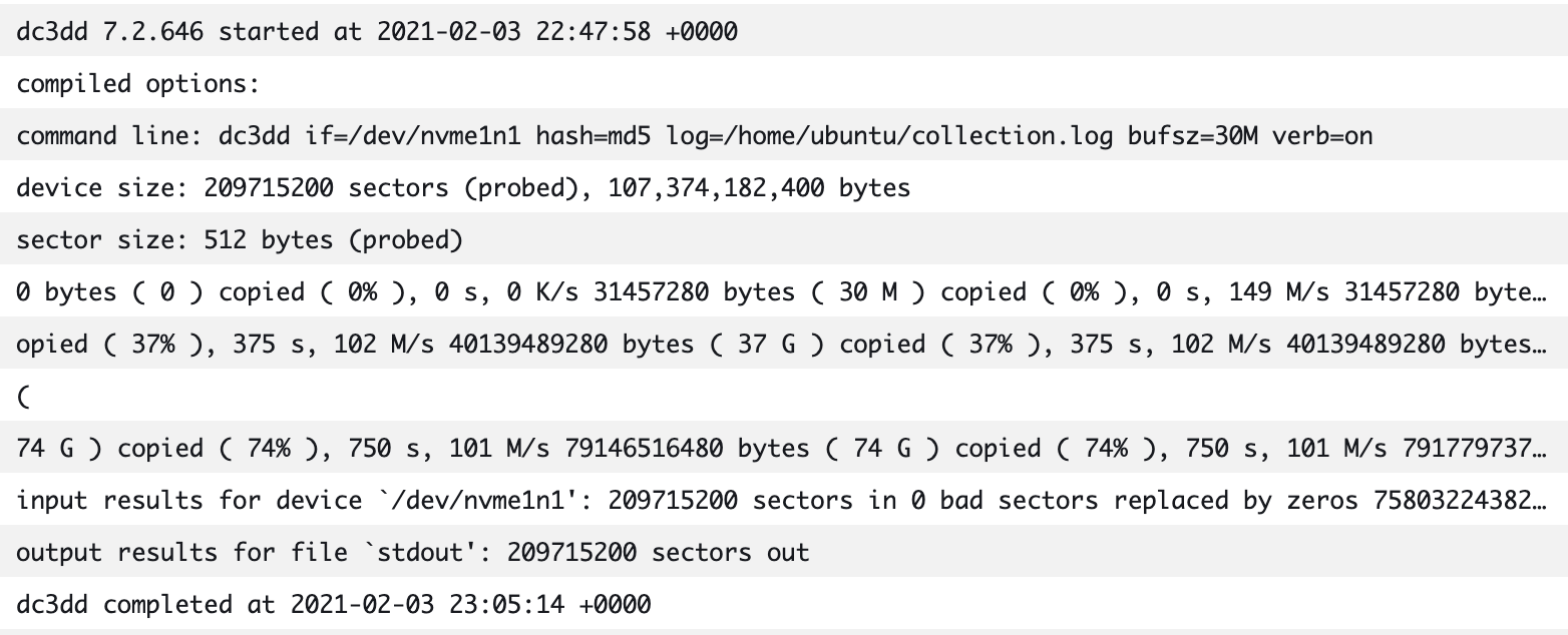
Figure 6: Forensic Disk Capture logs
Cost and capture times
This solution may save you money over a traditional system that requires bastion hosts (jump boxes) and forensic instances to be readily available. With AWS, you pay only for the individual services you need, for as long as you use them. The cost of this solution is minimal, because charges are only incurred based on the logs or artifacts that you store in CloudWatch or Amazon S3, and the invocation of the Step Functions workflow. Additionally, resources such as the collectorVM are only created and used when needed.
This solution can also save you time. If an analyst was manually working through this workflow, it could take significantly more time than the automated solution. The following are some examples of collection times. You can see that even when the manual workflow time increases, the automated workflow time stays the same, because of how the solution scales.
Scenario 1: EC2 instance with one 8GB volume
- Automated workflow: 11 minutes
- Manual workflow: 15 minutes
Scenario 2: EC2 instance with four 8GB volumes
- Automated workflow: 11 minutes
- Manual workflow: 1 hour 10 minutes
Scenario 3: Four EC2 instances with one 8GB volume each
- Automated workflow: 11 minutes
- Manual workflow: 1 hour 20 minutes
Clean up and delete artifacts
To clean up the artifacts from the solution in this post, first delete all information in your artifact S3 bucket. Then delete the diskForensics stack, followed by the diskForensicImageBuilder stack, and finally the diskMember stack. You must also manually delete any EBS volumes or EBS snapshots created by the pipeline, these are not deleted automatically. You must also manually delete the AMI and images that are created and published by Image Builder.
Considerations
This solution covers EBS volume storage as the target for forensic disk capture. If your instances use Amazon EC2 Instance Stores in your environment, then you cannot snapshot and copy those volumes, because that data is not included in an EC2 snapshot operation. Instead, you should consider running the commands that are included in collector.sh script with AWS Systems Manager. The collector.sh script is included in the Image Builder recipe and uses dc3dd to stream a copy of the volume to Amazon S3.
Conclusion
Having this solution in place across your AWS accounts will enable fast response times to security events, as it helps ensure that forensic artifacts are collected and stored as quickly as possible. Download the .zip file for the solutions in CloudFormation, so that you can deploy this solution and get started on your own forensic automation workflows. For the talks describing this solution, see the video of SEC306 from Re:Invent 2020 and the AWS Online Tech Talk AWS Digital Forensics Automation at Goldman Sachs.
If you have feedback about this post, submit comments in the Comments section below. If you have questions about this post, start a new thread on the Amazon GuardDuty forum or contact AWS Support.
Want more AWS Security how-to content, news, and feature announcements? Follow us on Twitter.